PMS 11
1 / 17
V1.1
PMS 11
Embedded Particle Counter
Specifications

PMS 11
2 / 17
V1.1
Contents
1. Overview .......................................................................................................................................... 3
2. Working Principle ........................................................................................................................... 4
3. Technical Specifications ................................................................................................................ 5
4. Electrical Specifications ................................................................................................................ 6
5. Communication Protocol .............................................................................................................. 7
6. Item Dimension ............................................................................................................................ 15
7. Precautions for Installation and Operation ........................................................................... 15
8. Note and Warning ........................................................................................................................ 16
PMS 11
3 / 17
V1.1
1. Overview
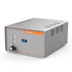
PMS 11 series is an embedded and remote particle counter specially designed to provide solutions for the
online monitoring industry of atmospheric environment. It is widely used in filter testing, dust monitoring
and other air monitoring systems.
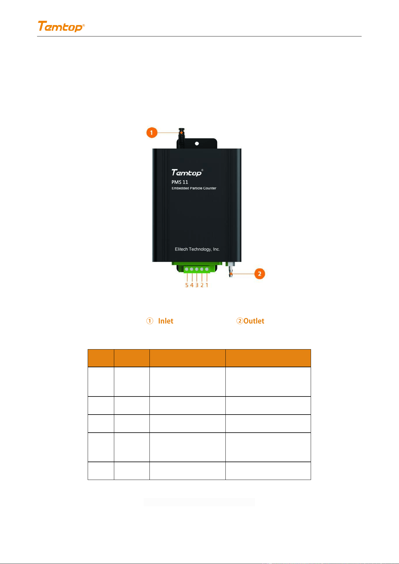
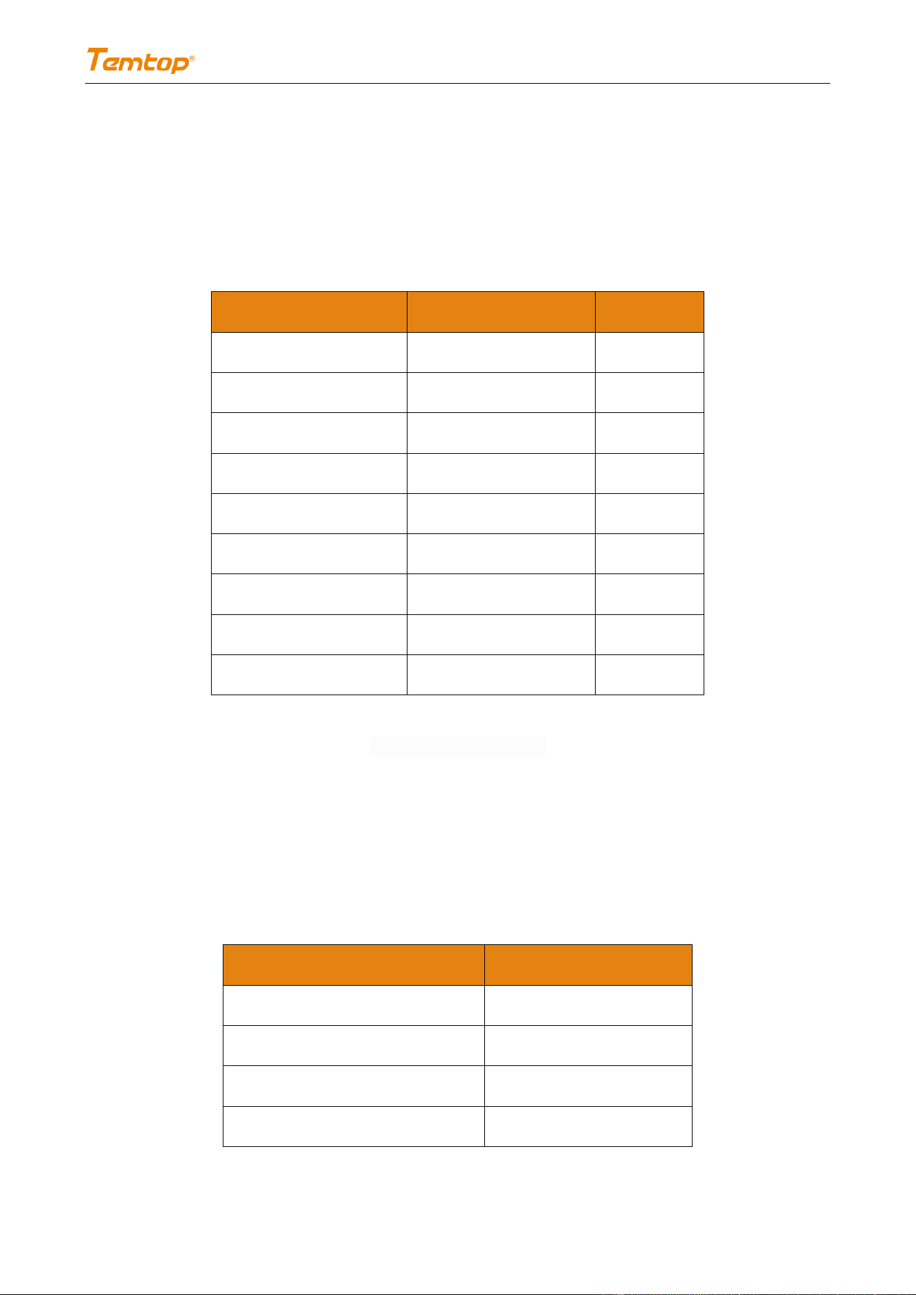
Pin
Name
Description
Note
1
VCC
Device power supply
(positive)
12V
2
GND
Device grounding
——
3
TX(A)
Communication sending pin
(RS485+) serial sending
4
RX(B)
Communication receiving
pin
(RS485-) serial receiving
5
NC
——
——
Table 1 Definition of Hardware Interface
PMS 11
4 / 17
V1.1
2. Working Principle
This monitor relies on MIE scattering principle to monitor the concentration of particles. When the outside
air passes through the light collection chamber uniformly, the particles in the sampled gas will scatter
through the light beam. The photoelectric collection unit converts the scattered light signal into a voltage
pulse signal, which is converted into a digital signal after pre-amplification and AD conversion. The number
of voltage pulses measured is the number of particles, and the amplitude of voltage pulses reflects the size
of optical equivalent size of particle. The standard substance is used to calibrate the monitor after the
particle conversion, so as to determine the concentration of particles in the testing environment.
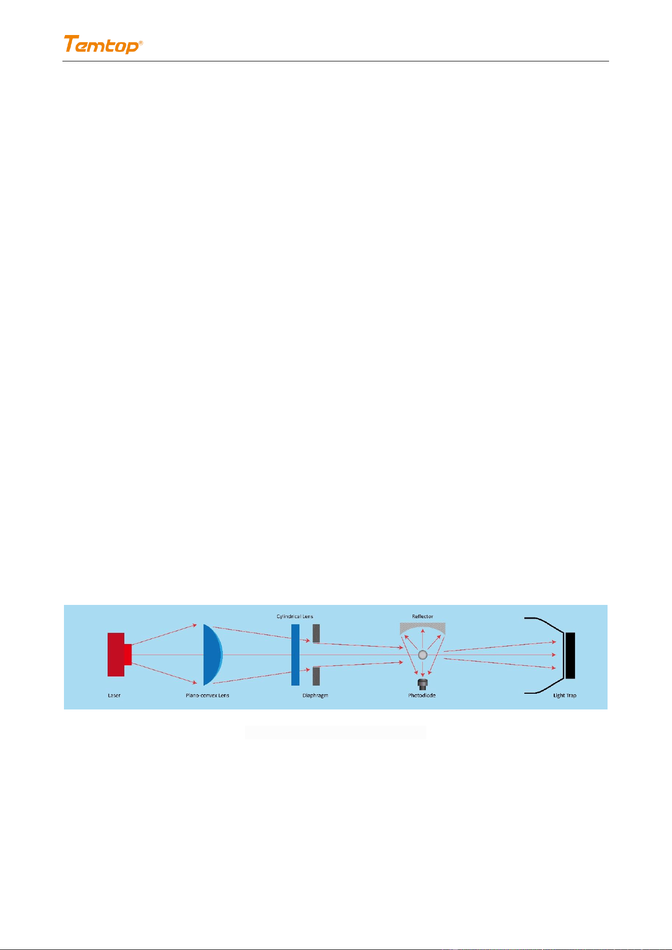
2.1 MIE scattering principle
A scattering occurred when the diameter of particles in the atmosphere is equal to the wavelength of
radiation is called the MIE scattering. The scattering intensity of MIE scattering is inversely proportional to
the second power of the wavelength. Unlike Rayleigh scattering enjoying a symmetrical distribution, MIE
scattering has stronger scattering in the forward direction than in the backward direction, with a more
obvious directivity.
2.2 Optical-mechanical structure and principle
Fig. 1 Analysis Chart of Light Refraction

PMS 11
5 / 17
V1.1
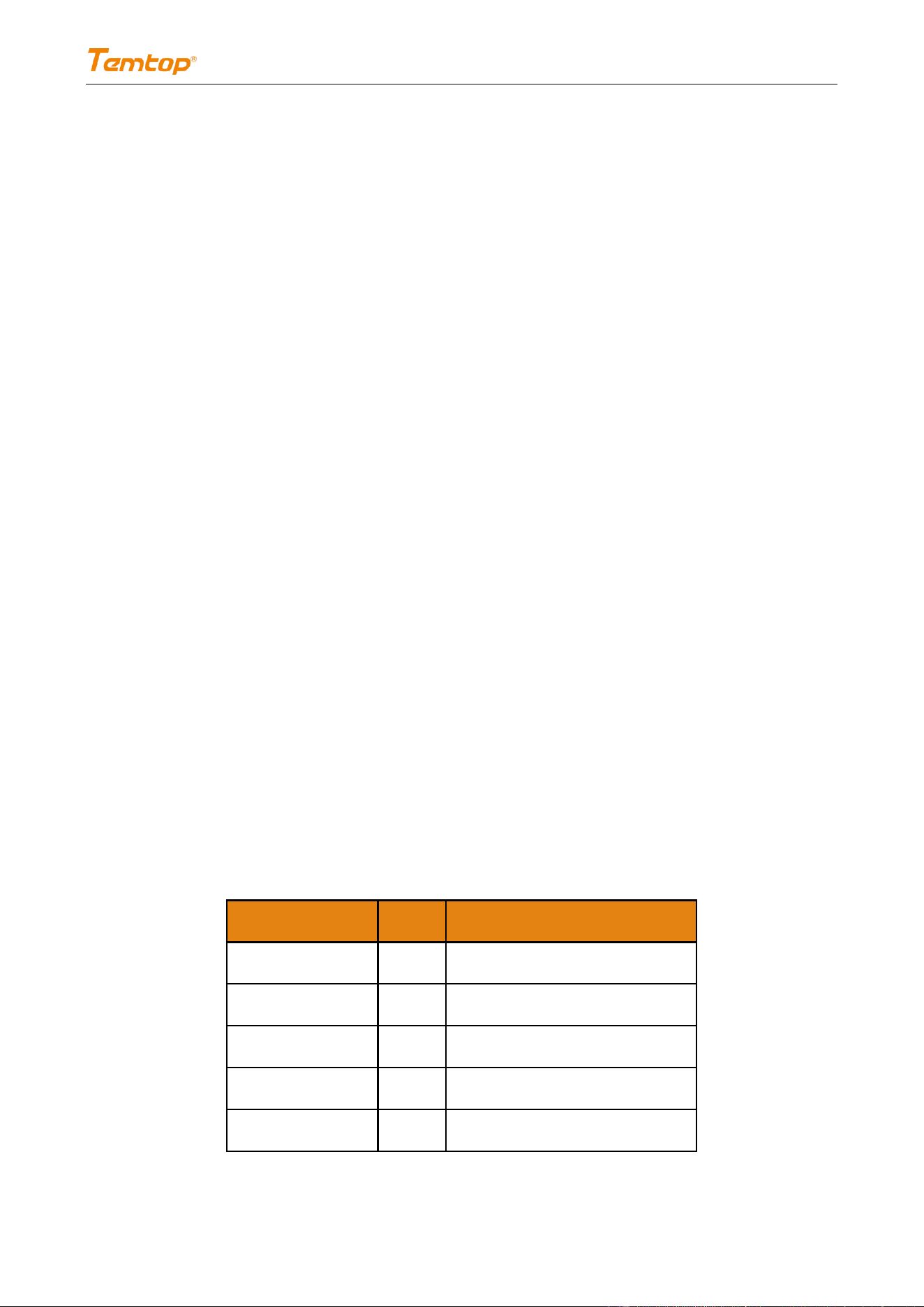
3. Technical Specifications
PMS 11
Unit
Note
Particle Size Range
0.3μm,0.5μm, 0.7μm,
1.0μm, 2.5μm, 5.0μm
P/L
Customize
Concentration Range
105,900
P/L
Repeatability
≤±30% of Relative Standard
Deviation
-
-
Resolution
1
P
-
Light Source
Laser Diode
-
-
Sampling Period
6
s
Communication
RS485
-
Flow Rate
1.1 (0.04)
L/min
(CFM)
Accuracy ±5%
Weight
350
g
-
Operation Environment
5℃~45℃, <90%RH
-
Storage Environment
-10℃~50℃, <90%RH
-
Size
113*88*38
mm
Excluding air inlet and
outlet
Table 2 Specifications of Particle Counter PMS 11
PMS 11
6 / 17
V1.1
4. Electrical Specifications
4.1 Electrical properties
Standard output (Temperature 25℃, Humidity 0-50% RH and 12V power supply voltage).
Parameters
Values
Unit
Rated voltage
DC 12
V
Standby current
30
mA
Average current
350
mA
Maximum current
400
mA
Starting current
700
mA
High-level input voltage
6
V
Low-level input voltage
-6
V
High-level output voltage
6
V
Low-level output voltage
-6
V
Table 3 Electrical Properties
4.2 Absolute limit values
The reliability of the device may be affected under the limit conditions for a long time.
Exceeding the following parameters range (Table 4) may cause permanent damage to the device.
Parameters
Range
Power supply voltage
11.5-12.5V
Voltage at I/O pin
-6-6 V
Working temperature range
-10-60 °C
Storage temperature range
-20-70 °C

PMS 11
7 / 17
V1.1
Working humidity range
0-95%RH (non-condensation)
Lightning surge
2KV
Static electricity
1KV for terminal test
8KV for test voltage of other
surfaces
Table 4 Absolute Limit Values
5. Communication Protocol
UART parameters:
-- Baud rate: 9600
-- Data bit: 8
-- Check bit: None
-- Stop bit: 1
Communication mode:
-- RS485 (Modbus RTU)
Address:
-- The default factory address of the monitor is 0x01 (or 0xFE, as Any Sensor).
Command mode:
-- The slave (monitor) is in the receiving state, only responding to the command of the host, not actively
sending the command. As the monitor needs 6 seconds to start, it will NOT response to any command
after the waiting time elapse.
Working mode:
-- Continuous measurement: The monitor works continuously.
PMS 11
8 / 17
V1.1
-- Intermittent mode: The sampling time/sampling interval can be set (The intermittent time can be set
by the users, and the monitor normally responds to the command of the host during the intermittent
mode)
-- The default factory setting of the monitor is intermittent mode, measuring for 60 seconds and stopping
for 60 seconds.
Checksμm:
-- CRC-16(Modbus), with high bytes before low bytes.
5.1 Format of host communication protocol
Restrictions:
1. Read-only register and read-write register are not allowed to overlap.
2. Bit addressing (coil and discrete input) cannot be realized.
3. Only achieved writing the single register function, writing multi-register is not supported.
4. The total number of registers is limited; it currently supports 32 input registers and 32 hold registers.
5. The current version does not support file transfer with large amount of data.
6. See table 1 and table 2 for register details. All registers are 16-bit words and register address is register
number -1.
Input Register, as shown in Table 5.
Data No.
Address
Definition
IR1
0
For later extended use
IR2
1
For later extended use
IR3
2
For later extended use
IR4
3
>0.3μm, high bytes
IR5
4
>0.3μm, low bytes
PMS 11
9 / 17
V1.1
IR6
5
>0.5μm, high bytes
IR7
6
>0.5μm, low bytes
IR8
7
>0.7μm, high bytes
IR9
8
>0.7μm, low bytes
IR10
9
>1.0μm, high bytes
IR11
10
>1.0μm, low bytes
IR12
11
>2.5μm, high bytes
IR13
12
>2.5μm, low bytes
IR14
13
>5.0μm, high bytes
IR15
14
>5.0μm, low bytes
IR16
15
For later extended use
IR17
16
For later extended use
IR18
17
For later extended use
IR19
18
For later extended use
IR20
19
For later extended use
IR21
20
For later extended use
IR22
21
For later extended use
IR23
22
For later extended use
IR24
23
For later extended use
IR25
24
For later extended use
IR26
25
For later extended use
IR27
26
For later extended use
IR28
27
For later extended use
IR29
28
For later extended use
IR30
29
For later extended use
Table 5 Input Register

PMS 11
10 / 17
V1.1
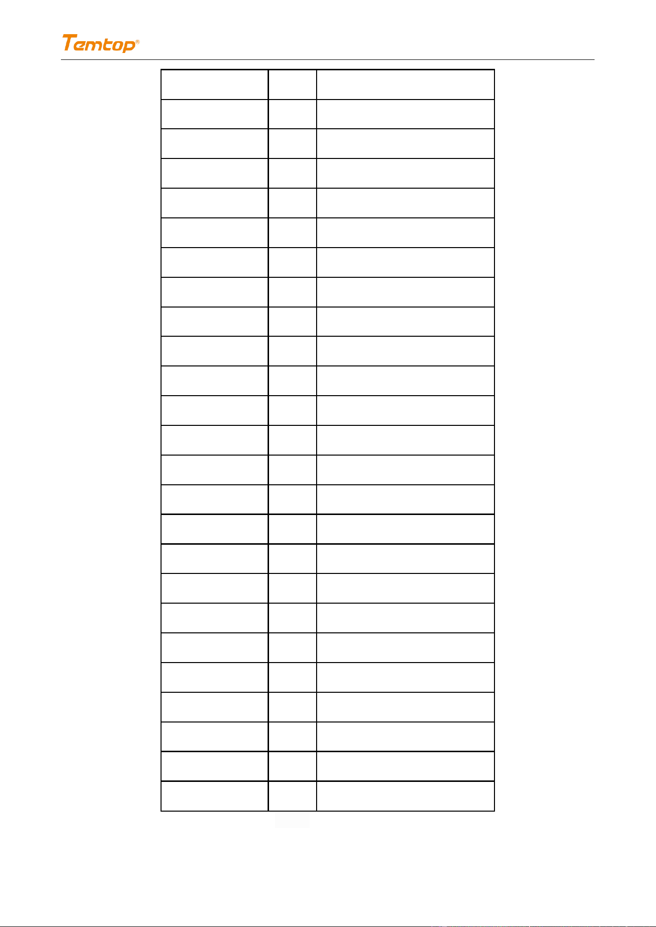
See Table 6 for the description of save register.
Data No.
Address
Definition
Meaning
IR1
0
For later extended use
IR2
1
Special command register
Command
Parameter
0x7C
0x06 Start Measurement
0x07 Stop Measurement
IR3
2
Address setting register
Slave Address (1-247)
IR4
3
Mode switching register
0x00 Continuous Working Mode
0x01 Intermittent Working Mode
IR5
4
Sample interval register
0xxx Sample interval setting (20~3600s)
IR6
5
Intermittent interval register
0xxx Intermittent interval setting (20~3600s)
IR7
6
0.3μm particle calibration
coefficient
User computing coefficient multiply by 10,000
(2000-65535)
IR8
7
0.5μm particle calibration
coefficient
User computing coefficient multiply by 10,000
(2000-65535)
IR9
8
0.7μm particle calibration
coefficient
User computing coefficient multiply by 10,000
(2000-65535)
IR10
9
1.0μm particle calibration
coefficient
User computing coefficient multiply by 10,000
(2000-65535)
IR11
10
2.5μm particle calibration
coefficient
User computing coefficient multiply by 10,000
(2000-65535)
IR12
11
5.0 μm particle calibration
coefficient
User computing coefficient multiply by 10,000
(2000-65535)
IR13
12
For later extended use
IR14
13
For later extended use
IR15
14
For later extended use
IR16
15
For later extended use
IR17
16
For later extended use
IR18
17
For later extended use
IR19
18
For later extended use
IR20
19
For later extended use
IR21
20
For later extended use
IR22
21
For later extended use
IR23
22
For later extended use
IR24
23
For later extended use
IR25
24
For later extended use
PMS 11
11 / 17
V1.1
IR26
25
For later extended use
IR27
26
For later extended use
IR28
27
For later extended use
IR29
28
For later extended use
IR30
29
For later extended use
IR31
30
For later extended use
IR32
31
For later extended use
Table 6 Description of Save Register
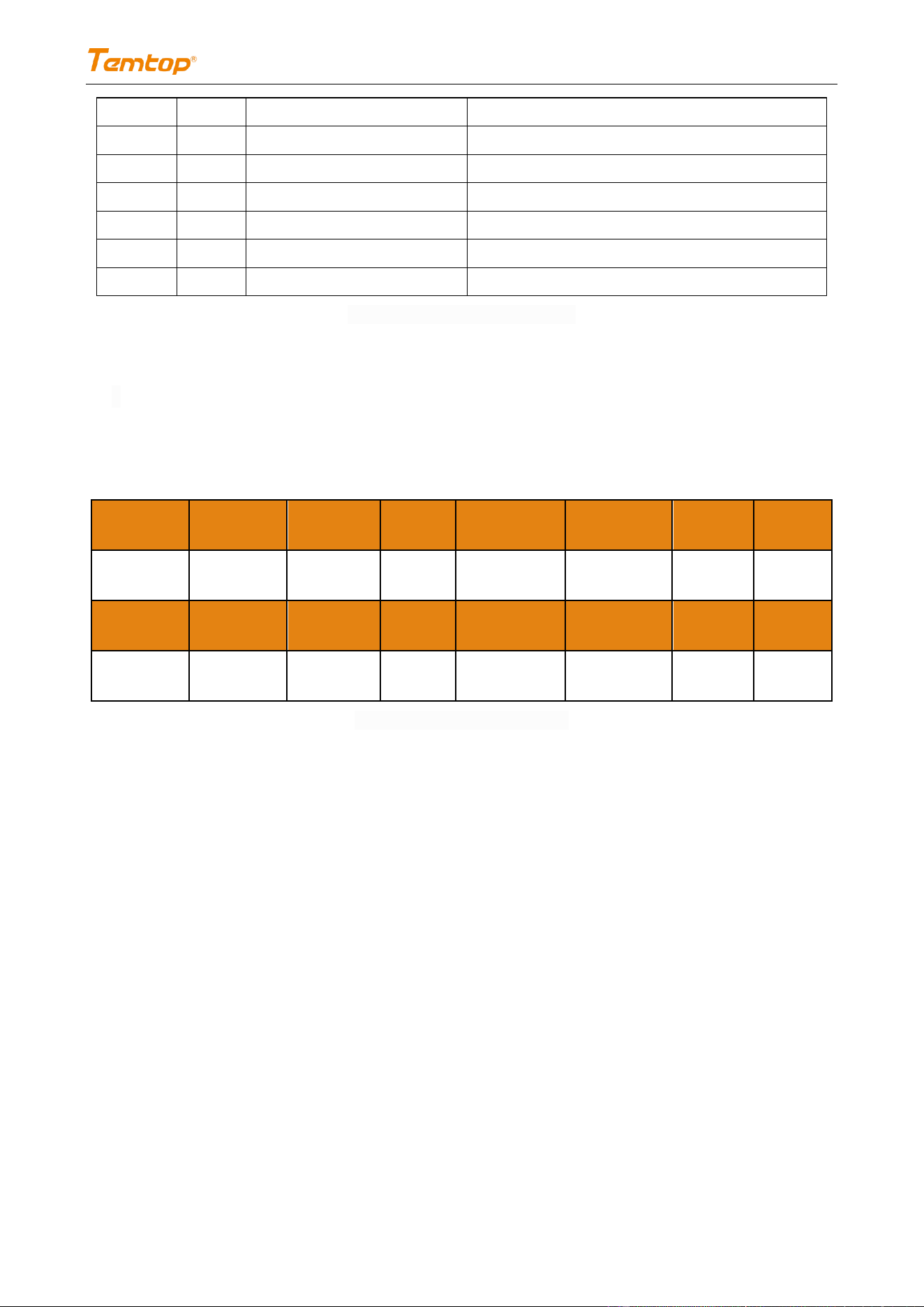
5.2 Format of host communication protocol
The response length of slave is not fixed and changed according to the command of host (Table 7).
Start symbol 1
Start symbol 2
Slave address
Command
High data length
Low data length
High data 0
Low data 0
0x4A
0x43
ADDR
CMD
LENH
LENL
DATA0H
DATA0L
High data 1
Low data 1
……
……
High data N
Low data N
High check
Low check
DATA1H
DATA1L
……
……
DATANH
DATANL
0xXX
0xXX
Table 7 Response Format of Slave
Note: The address/function code is defined by the host (After modifying the device address, the address in the
protocol is updated to the new address); see 5.3 command example for the specific response data of slave.
5.3 Command examples
Application Conditions:
a. Assume as a single sensor (any sensor, use address 254)
b. The value is hexadecimal data
c. Take the address bit as 0xFE for example
5.3.1 Obtaining the concentration value
Read the number of particles above 0.3 μm, 1.0 μm, 2.5 μm.
Example:

PMS 11
12 / 17
V1.1
number of particles above 0.3μm: 0x00002316 (actual value is 8982 P/L),
number of particles above 1.0μm: 0x00001016 (actual value is 4118 P/L),
number of particles above 2.5μm: 0x00000616 (actual value is 1558 P/L).
Host
Read the number of particles above 0.3μm:
0xFE 0x04 0x00 0x03 0x00 0x02 0x95 0xC4
Read the number of particles above 0.7μm:
0xFE 0x04 0x00 0x04 0x00 0x02 0x24 0x05
Read the number of particles above 2.5μm:
0xFE 0x04 0x00 0x05 0x00 0x02 0x75 0xC5
Slave
Read the number of particles above 0.3μm:
0xFE 0x04 0x04 0x00 0x00 0x23 0x16 0x6C 0x75
Read the number of particles above 0.7μm:
0xFE 0x04 0x04 0x00 0x00 0x10 0x16 0x78 0x85
Read the number of particles above 2.5μm:
0xFE 0x04 0x04 0x00 0x00 0x06 0x16 0x76 0xE5
Read the number of particles above 0.3μm, 0.5μm, 1.0μm, 2.5μm, 5.0μm.
Example:
number of particles above 0.3μm: 0x00002316 (actual value is 8982 P/L),
number of particles above 0.5μm: 0x00001D4C (actual value is 7500P/L),
number of particles above 0.7μm: 0x00001914 (actual value is 6420P/L),
number of particles above 1.0μm: 0x00001016 (actual value is 4118P/L),
number of particles above 2.5μm: 0x00000616 (actual value is 1558P/L),
number of particles above 5.0μm: 0x00000140 (actual value is 320P/L).
Host
0xFE 0x04 0x00 0x03 0x00 0x0C 0x14 0x00
Slave
0xFE 0x04 0x18 0x00 0x00 0x23 0x16 0x00 0x00 0x1D 0x4C 0x00
0x00
0x19 0x14 0x00 0x00 0x10 0x16 0x00 0x00 0x06 0x16 0x00 0x00
0x01
0x40 0x40 0xD8
PMS 11
13 / 17
V1.1
5.3.2 Start/Stop
After the host sends the Start/Stop command, the slave performs the corresponding action and returns the
response command.
Example:
Host
Start Measurement:
0xFE 0x06 0x00 0x01 0x7C 0x06 0x6C 0XC7
Stop Measurement:
0xFE 0x06 0x00 0x01 0x7C 0x07 0xAD 0X07
Slave
Start Measurement:
0xFE 0x06 0x00 0x01 0x7C 0x06 0x6C 0XC7
Stop Measurement:
0xFE 0x06 0x00 0x01 0x7C 0x07 0xAD 0X07
5.3.3 Setting Slave Address
After the host sends the Setting Slave Address command, the slave performs the corresponding action and
returns the response command.
Example:
Host
0xFE 0x06 0x00 0x02 0x00 0x03 0x7C 0X04
Slave
0xFE 0x06 0x00 0x02 0x00 0x03 0x7C 0X04
5.3.4 Read Device Address
After the host sends the Read Device Address command, the slave performs the corresponding action and
returns the response command.
Example: The Device address is 03.
Host
0xFE 0x03 0x00 0x02 0x00 0x01 0x31 0xC5
Slave
0xFE 0x03 0x02 0x00 0x03 0xEC 0x51
PMS 11
14 / 17
V1.1
5.3.4 Switching Continuous/Intermittent Working Mode
After the host sends the Switching Continuous/Intermittent Working Mode command, the slave performs
the corresponding action and returns the response command.
Example:
5.3.5 Write Hold Register Continuously
The calibration coefficient must be written continuously if using the 0x10 function, the 0x10 can only be
used to write registers. Using the 03 function code can read the calibration coefficient.
Example: The actual coefficient is k(0.3μm):1.2345 k(0.5μm):1.2345 k(0.7μm):1.2345
k(1.0μm):1.2345 k(2.5μm):1.2345 k(5.0μm):1.2345
The coefficient that need to send is 1.2345*10000 = 12345 = 3039 (hexadecimal)
Host
0xFE 0x10 0x00 0x06 0x00 0x06 0x0C 0x30 0x39 0x30 0x39 0x30
0x39
0x30 0x39 0x30 0x39 0x30 0x39 0x3A 0xFA
Slave
0xFE 0x10 0x00 0x00 0x00 0x06 0x54 0x04
Host
Continuous Working Mode:
0xFE 0x06 0x00 0x03 0x00 0x00 0x6D 0XC5
Intermittent Working Mode:
0xFE 0x06 0x00 0x03 0x00 0x01 0xAC 0X05
Slave
Continuous/Intermittent Mode:
0xFE 0x06 0x00 0x03 0x00 0x00 0x6D 0XC5
Intermittent Working Mode:
0xFE 0x06 0x00 0x03 0x00 0x01 0xAC 0X05
PMS 11
15 / 17
V1.1
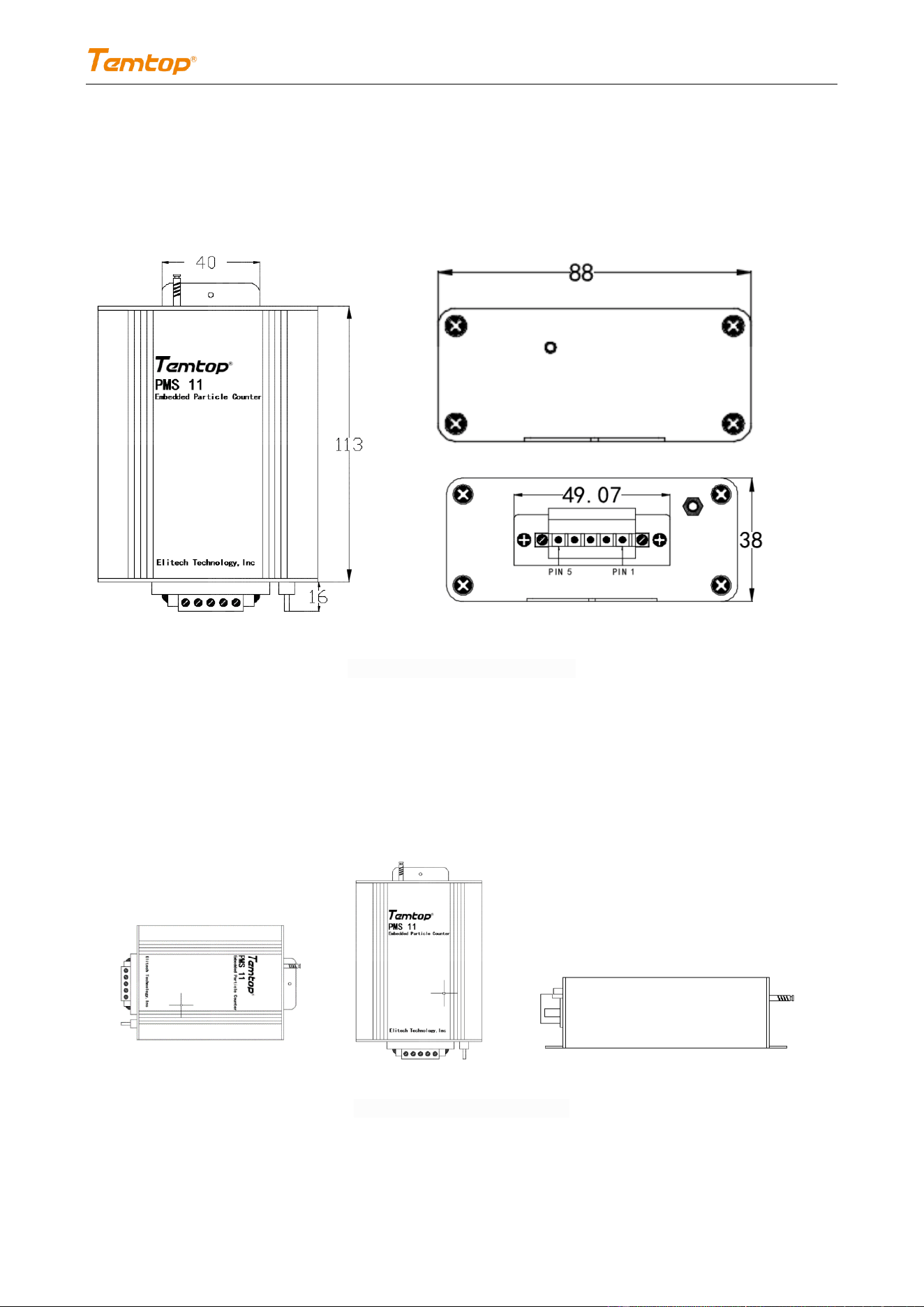
6. Item Dimension
Fig.2 Dimension Drawing of PMS 11
7. Precautions for Installation and Operation
7.1 Recommended installation method
7.1 Correct installation method
Fig. 3 Correct Installation Method
PMS 11
16 / 17
V1.1
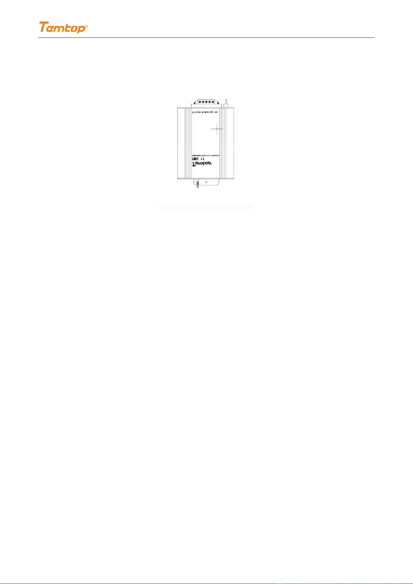
7.2 Wrong installation method
Fig. 4 Wrong Installation Method
8. Note and Warning
Note
⚫ Please read this specification carefully before purchase, otherwise, Elitech Technology, Inc., Temtop,
and Lekong (Shanghai) Environmental Technology Co., Ltd. are not responsible for any possible danger,
damage, or losses.
⚫ As the device is not directly in contact with the monitoring environment (for example, installed in the
equipment enclosures), the air inlet of the monitor shall be connected to the external probe of the
enclosure, with the length of the connecting hose between them controlled within 30cm, so as to
obtain accurate measurement results of sampling;
⚫ The external probe of the enclosure shall have the ability of wind proof, coarse filtration and
waterproof.
Warning
⚫ Please install the device referring to 8.2. It is forbidden to open the device shell for use.
⚫ The device is equipped with a laser transmitter internally, which may cause the operation personnel to
be accidentally exposed to laser radiation due to private maintenance. The maintenance of the device

PMS 11
17 / 17
V1.1
shall be performed by the manufacturer’s special personnel.
⚫ The implementation of product technical indicators should be used in a standard atmospheric pressure
environment. The manufacturer will not be responsible for any errors in the introduction of products
and data and product damage in any high-pressure/low-pressure environment.
⚫ Elitech Technology, Inc., Temtop and Lekong (Shanghai) Environmental Technology Co., Ltd. shall not be
liable for any faults caused by improper use of this product. Such faults will be deemed to be beyond
the scope of warranty service, and manufacturers can provide paid service assistance.
Please be noted that the specifications, functions, interfaces, etc. of the product may be
different from the content shown in the manual due to improvements and upgrades. Please
kindly confirm the latest information and information with your sales representative.
Temtop US
Elitech Technology, Inc.
1551 McCarthy Blvd, Milpitas, CA 95035 USA
Tel: +1 408-898-2866
Website: www.temtopus.com