
PMS 21
Remote Particle Counter
User Manual
PMS 21 Remote Particle Counter User Manual
Page 1
Notices about this User Manual
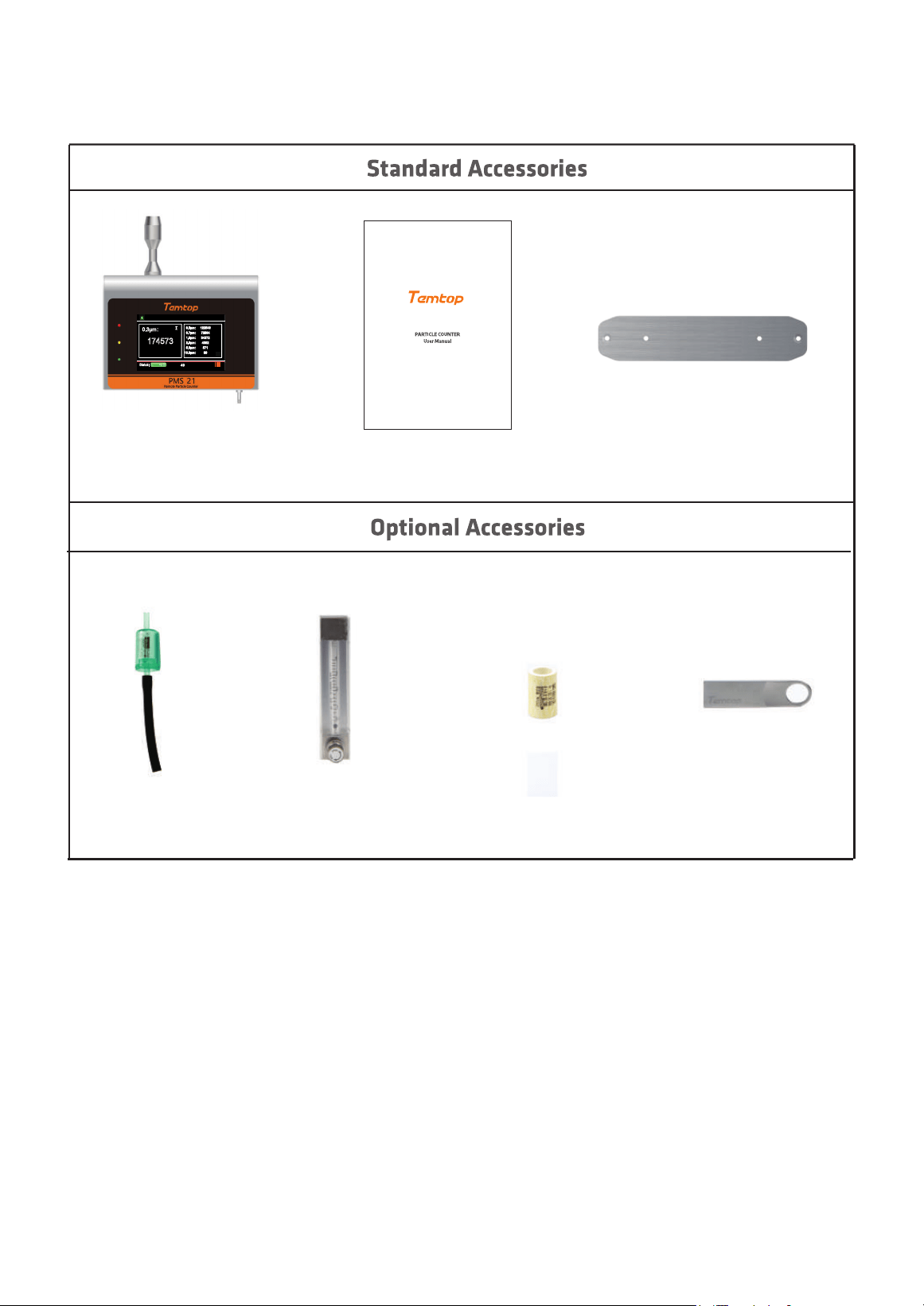
After opening the monitor case, make sure that the parts in the case are complete according to
the following table. If anything is missing, please contact our company.
PMS 21
PMS 21
PMS 21 Remote Particle Counter User Manual
Page 2
0.3μm:
0.5μm:
0.7μm:
1.0μm:
2.5μm:
5.0μm:
10.0μm:
Status:
M³
Measuring
02-28-2025 09:09:02
174573
122546
72564
34372
4382
571
89
49
∑
Fixed PegboardUser Manual
Flow Meter Filter Element USB Flash DriveFilter Tube
4
4
5
5
6
6
10
11
13
13
14
14
14
16
16
16
19
19
19
19
20
20
21
22
RS-485
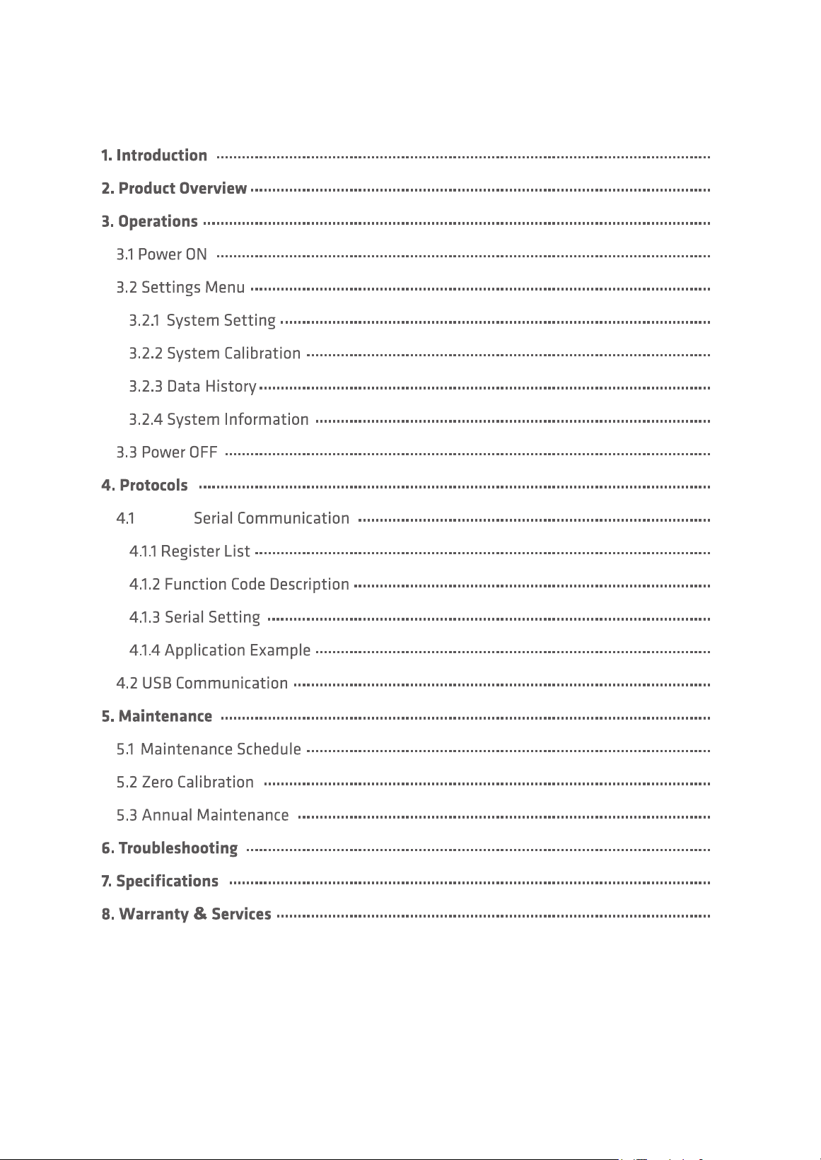
Table of contents
PMS 21 Remote Particle Counter User Manual
Page 3
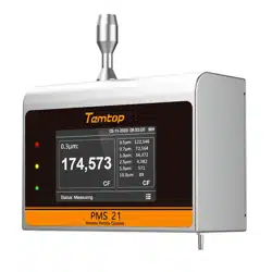
The PMS 21 is a professional, DC 24V powered, remote particle counter with seven channels
of simultaneous detection, outputting the number of particles at 0.3 µm, 0.5 µm, 0.7 µm,
1.0 µm, 2.5 µm, 5.0 µm and 10.0 µm.
Large screen display, touch screen operation, simple and ecient, suitable for multi-scene
rapid detection. At the same time, PMS 21 supports 485 communication and interaction.
1. lntroduction
2. Product 0verview
PMS 21 Remote Particle Counter User Manual
Page 4
0.3μm:
0.5μm:
0.7μm:
1.0μm:
2.5μm:
5.0μm:
10.0μm:
Status:
M³
Measuring
02-28-2025 09:09:02
174573
122546
72564
34372
4382
571
89
49
∑
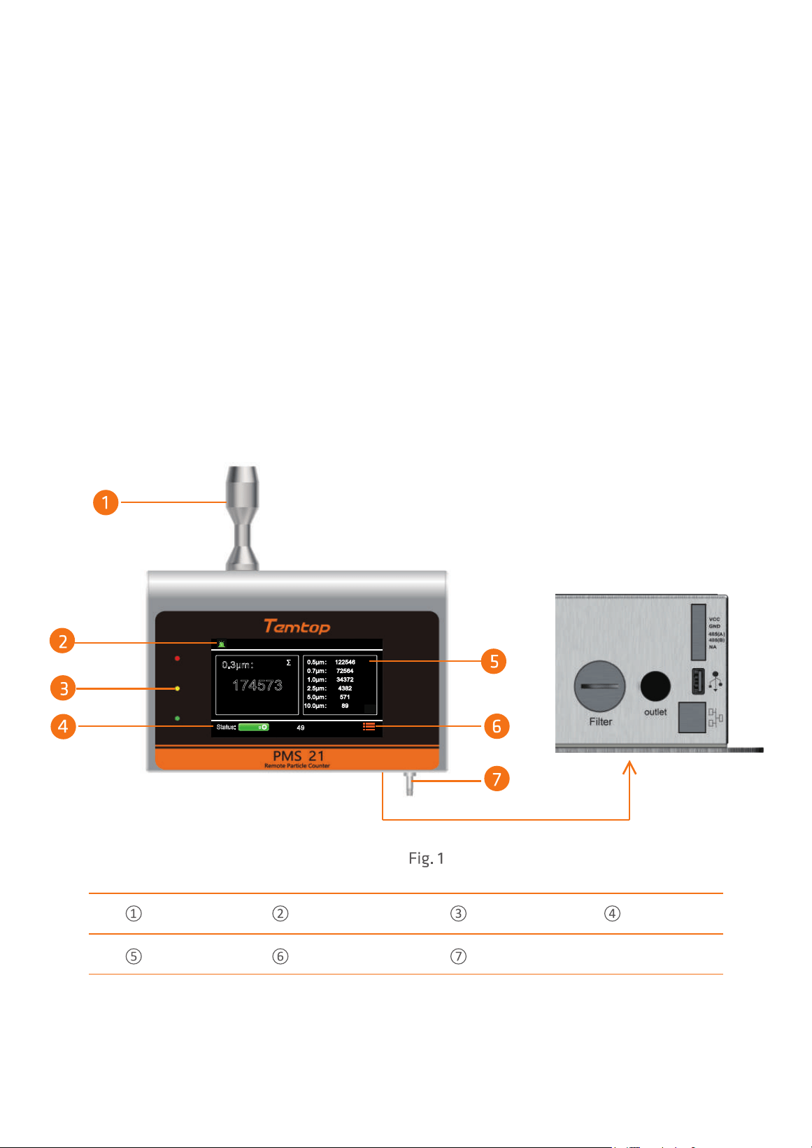
Alarm Button
Status Light*
Status
Touch Screen
Menu
Intake Duct
Air Outlet
* Red Light: Detection value exceeds the alarm threshold.
Yellow Light: Flow rate attenuation warning.
Green Light: Device in operation.
0.3μm:
0.5μm:
0.7μm:
1.0μm:
2.5μm:
5.0μm:
10.0μm:
Status:
M³
Measuring
02-28-2025 09:09:02
174573
122546
72564
34372
4382
571
89
49
∑
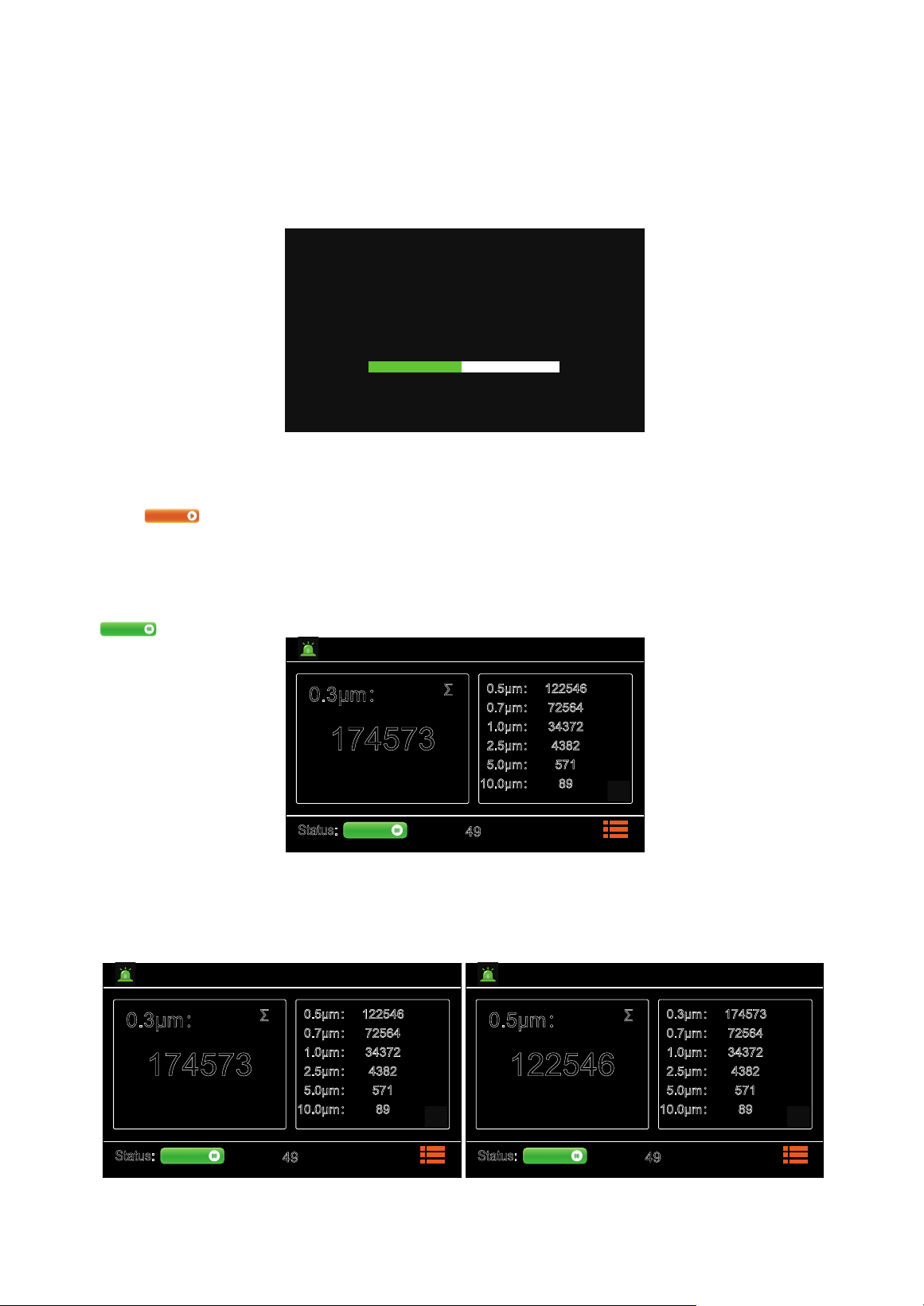
After power is applied, the instrument turns on and displays the initialisation screen (Fig.2).
3. 0nerations
3.1 Power ON
Do not use this monitor to delect heavy smoke,
high-concentration oil mist,or high-pressure gas
to avoid laser tip damage or air pump block.
IMPORTANT
47%
After initialisation, enter the main interface of the system.
Press to start the test, the interface displays the real-time data of all parameters, the default
sampling unit of the instrument is CF, the default sampling time is 60s (the sampling unit and time
can be set according to your needs, please refer to 3.2.1 Sampling Settings for details), and the status
bar at the bottom displays the sampling countdown.
The instrument defaults to continuous sampling, which can be paused during sampling by pressing
(Fig.3).
PMS 21 Remote Particle Counter User Manual
Page 5
Waiting
Measuring
By default, 0.3µm data is displayed in the main viewframe, and the items displayed in the main
viewframe can be switched by sliding up and down (Fig.4).
Fig.3
Fig.2
Fig.4
0.3μm:
0.5μm:
0.7μm:
1.0μm:
2.5μm:
5.0μm:
10.0μm:
Status:
M³
Measuring
02-28-2025 09:09:02
174573
122546
72564
34372
4382
571
89
49
∑
0.5μm:
0.3μm:
0.7μm:
1.0μm:
2.5μm:
5.0μm:
10.0μm:
Status:
M³
Measuring
02-28-2025 09:09:02
122546
174573
72564
34372
4382
571
89
49
∑
3.2 Settings Menu
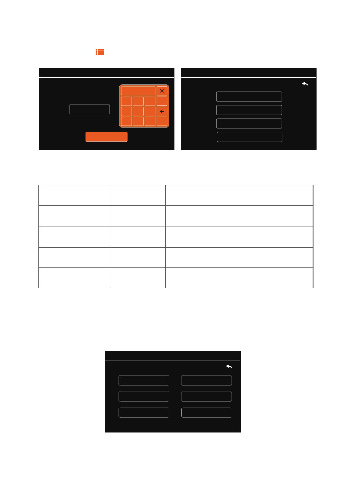
In Wait Mode, tap , then enter the password (initial password: "543210") to access the Settings
interface. Touch-click to select the function (Fig.5).
Fig.5
MENU options are as follows:
System Setting
System Calibration
Data History
System Information
MENU:
02-28-2025 09:09:02
Set system time, sample, COM, language,
backlight and alarm
System Setting
System Calibration
Data History
System Information
Menu
Display as...
Description
Setting
Calibration
History
Information
Calibrate zero
Query, download and delete the data
Display system information
02-28-2025 09:09:02
Backlight Adjustment
Time Setting
COM Setting
Sample Setting
Language Setting
Alarm Setting
MENU->Setting:
3.2.1 System Setting
In the system setting interface MENU -> Setting, you can set the time, sampling, COM,
language, backlight adjustment and alarm setting. Click the item to be set to make the
relevant settings (Fig.6).
Fig.6
PMS 21 Remote Particle Counter User Manual
Page 6
Password:
Login
MENU:
543210
02-28-2025 09:09:02
1 2 3
4 5 6
7 8
9
0
OK
******
PMS 21 Remote Particle Counter User Manual
Page 7
Time Setting
1 2 3
4 5 6
7 8
9
0
OK
MENU->Setting->Time:
Save
02-28-2025 09:09:02
02 - 18 - 2025
11 : 12 : 13
MENU->Setting->Time:
Save
02-28-2025 09:09:02
02 - 18 - 2025
11 : 12 : 13
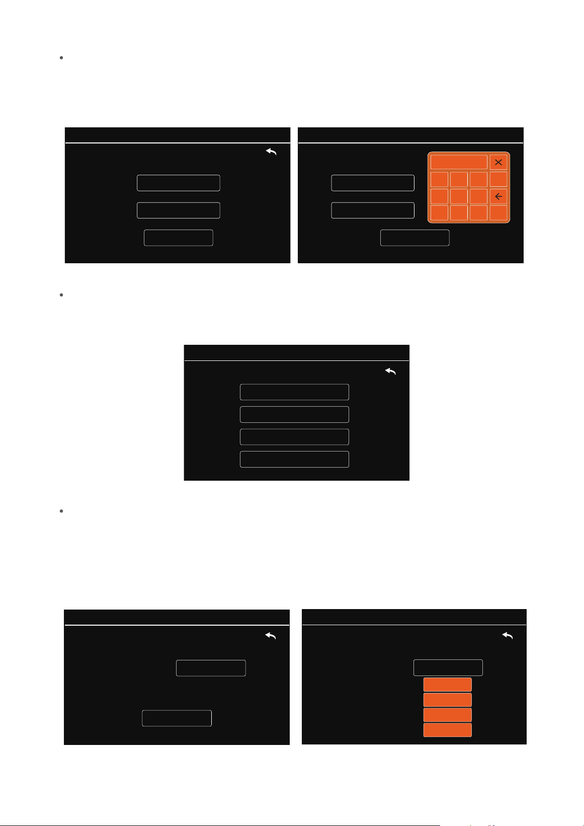
In the time setting interface, you can click on the value you want to set. The page will display an
orange data keyboard pop-up window. Click on the number you want to put on the keyboard and
then click on ‘OK’ to make sure. After finishing the settings, click on ‘Save’ to save the settings (Fig.7).
Sample Setting
Fig.7
In the Sample Setting interface, you can set the sample unit, counting mode, sample time and
hold time (Fig.8).
Fig. 8
MENU->Setting->Sample:
Sample Unit
Counting Mode
Hold Time
Sample Time
02-28-2025 09:09:02
Sample Unit
Click ‘Sample Unit’ to enter the Sample Unit setting interface. The device supports four counting
units: CF, L, M³, and TC. CF: number of particles per cubic foot. L: number of particles per litre.
M³: number of particles per cubic metre. TC: number of particles measured during the sampling time.
Click the location of the sampling unit to enter the drop-down box, select the sampling unit you want
to set, and then press ‘Save’ to save the settings (Fig.9).
MENU->Setting->Sample->Unit:
Save
Sample Unit:
02-28-2025 09:09:02
L
MENU->Setting->Sample->Unit:
Sample Unit:
CF
L
M³
02-28-2025 09:09:02
TC
Fig.9
PMS 21 Remote Particle Counter User Manual
Page 8
Counting Mode
Click ‘Counting Mode’ to enter the Counting Mode setting interface.
Click on the ‘∑’ or ‘∆’ location to access the drop-down box, select the Counting Mode you want to
set, and then press ‘Save’ to save the settings (Fig.10).
MENU->Setting->Sample->CountingMode:
Counting
Mode:
∑
∆
02-28-2025 09:09:02
MENU->Setting->Sample->CountingMode:
Save
Counting
Mode:
02-28-2025 09:09:02
∑
Fig.10
Sample Time
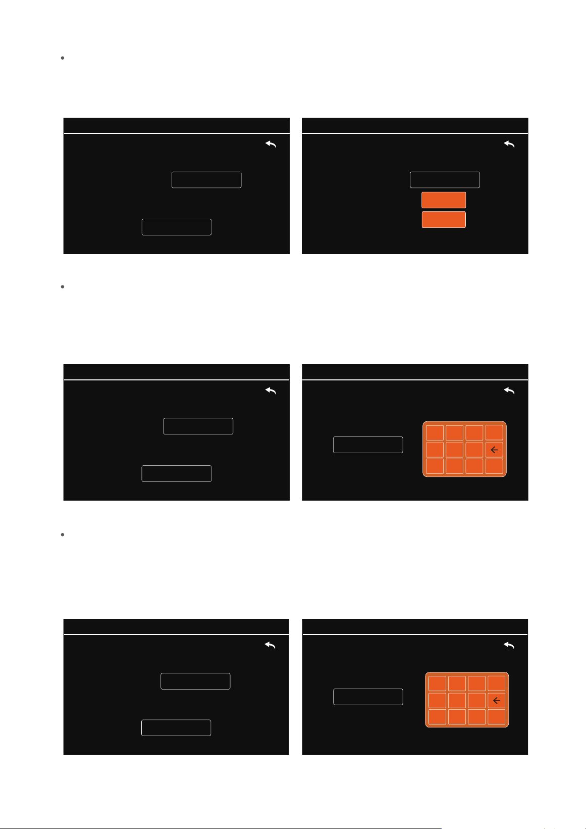
Click ‘Sample Time’ to enter the Sample Time setting interface.The device supports setting the sampling
time freely in the range of 10-3600 seconds. Click on the location of the sampling time and the page will pop
up with a Pop-up Orange Data Keyboard window. Click on the number to be entered on the keyboard and
click ‘OK’ to confirm. After completing the settings, click ‘Save’ to save the settings (Fig.11).
Fig.11
MENU->Setting->Sample->Time:
Save
Sample Time: Sec
02-28-2025 09:09:02
10
MENU->Setting->Sample->Time:
Sample Time:
Sec
1 2 3
4 5 6
7 8 9
0
OK
02-28-2025 09:09:02
Hold Time
Click ‘Hold Time’ to enter the Hold Time setting interface. The device supports setting the hold time freely
in the range of 0, 6-9999s. Click on the location of the hold time, and the page will pop up with the orange data
keypad window. Click on the number to be entered on the keyboard and click OK to confirm. After completing
the settings, click ‘Save’ to save the settings (Fig.12).
MENU->Setting->Sample->Hold Time:
Hold Time:
Sec
1 2 3
4 5 6
7 8 9
0
OK
02-28-2025 09:09:02
MENU->Setting->Sample->Hold Time:
Save
Hold Time:
Sec
02-28-2025 09:09:02
12
Fig.12
COM Setting
PMS 21 Remote Particle Counter User Manual
Page 9
Click ‘COM Setting’ to enter the COM setting interface.
Click the location of baud data to enter the drop-down box, select the baud rate you want to set from
the three baud rates of 9600, 19200, and 115200, and then press ‘Save’ to save the setting (Fig.13).
MENU->Setting->COM:
Baud:
9600
19200
115200
02-28-2025 09:09:02
MENU->Setting->COM:
Save
Baud:
02-28-2025 09:09:02
9600
Fig.13
Language Setting
MENU->Setting->Language:
Save
Language:
02-28-2025 09:09:02
English
MENU->Setting->Language:
Language:
English
中文
02-28-2025 09:09:02
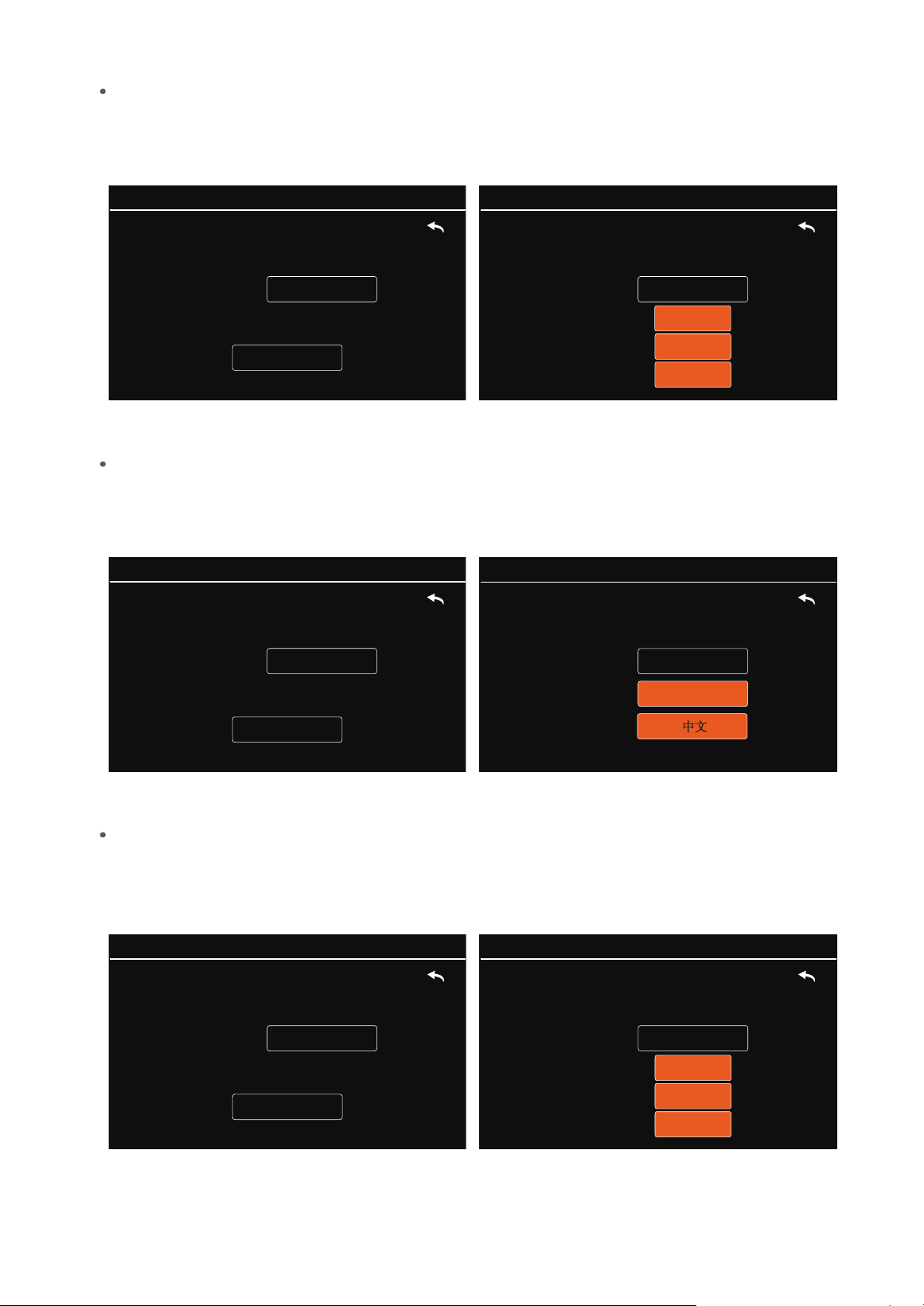
Click ‘Language Setting’ to enter the language setting interface.
Click the location of the language setting to enter the drop-down box, select the language to be set from
‘English’ and ‘中文’, and then press ‘Save’ to save the setting (Fig. 14).
Fig. 14
Backlight Adjustment
Click Backlight Adjustment Settings to enter the Backlight Adjustment Settings interface.
Click Backlight Level Position to enter the drop-down box, select the backlight level you want to set from
‘1’, ‘2’, and ‘3’ backlight levels, and then press ‘Save’ to save the setting (Fig. 15).
MENU->Setting->BackLight:
BackLight:
1
2
3
02-28-2025 09:09:02
MENU->Setting->BackLight:
Save
BackLight:
02-28-2025 09:09:02
3
Fig. 15
PMS 21 Remote Particle Counter User Manual
Page 10
Alarm Setting
Click ‘Alarm Setting’ to enter the alarm setting screen.
The device supports seven-channel alarm setting with threshold interval 0-999999999, click the
corresponding channel for alarm value editing, the page will pop up the orange data keyboard window.
Click the number to be entered on the keyboard and then click ‘OK’ to confirm. After completing the
settings, click ‘Save’ to save the settings (Fig. 16).
MENU->Setting->
Alarm
:
0.3:
1 2 3
4 5 6
7 8 9
0
OK
02-28-2025 09:09:02
Fig. 16
3.2.2 System Calibration
MENU->Setting->
Alarm
:
Save
0.3:
0.5:
0.7:
1.0:
2.5:
5.0:
10.0:
02-28-2025 09:09:02
4444444
999999999
999999999 999999999
999999999
999999999 999999999
In the System Calibration screen, you can perform zero calibration (Fig. 17).
MENU->Calibration:
Zero Calibration
02-28-2025 09:09:02
Flow Calibration
Fig. 17
Zero Calibration
MENU->Calibration->Zero:
Start Calibration
Please connect the filter to the monitor.
Press the
Start Calibration
button, wait for
180 seconds until the calibration completed.
02-28-2025 09:09:02
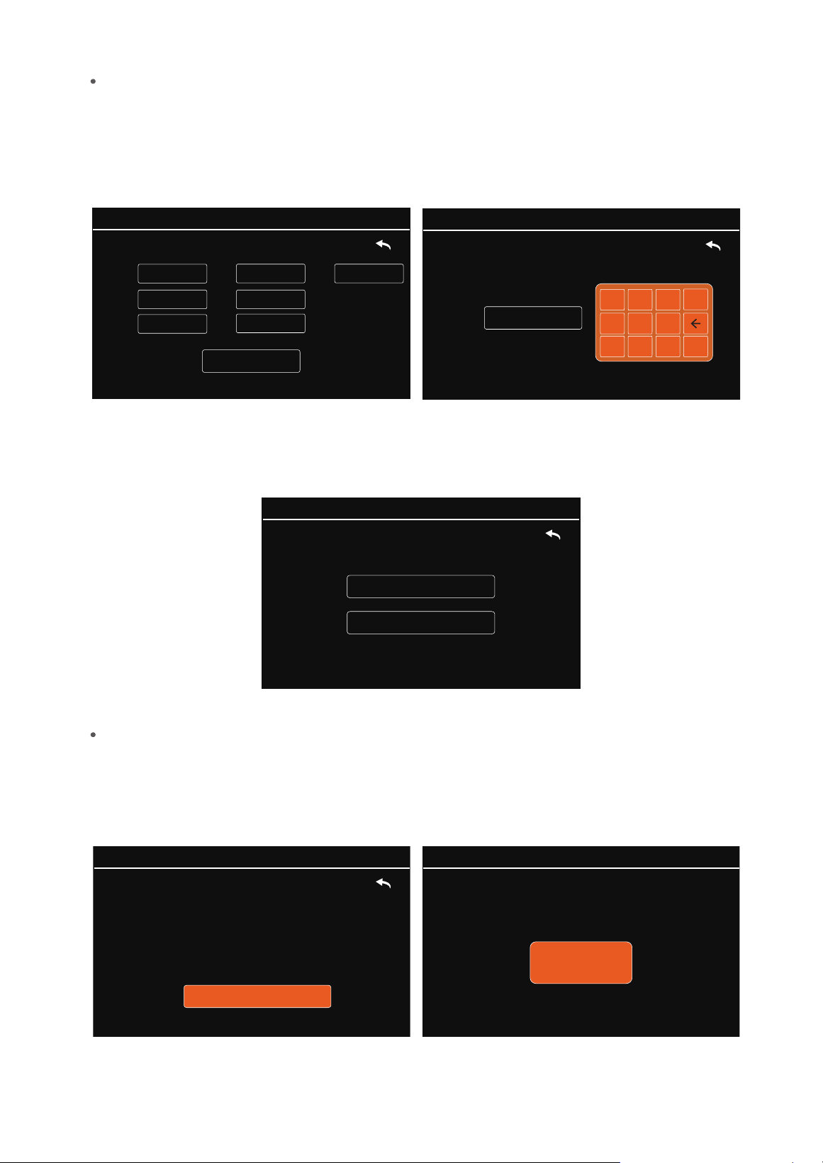
Click ‘Zero Calibration’ to enter the zero calibration interface.
Connect the filter and air inlet according to the prompts on the screen, click Start Calibration, the
calibration time is 180s, and the interface shows a countdown. After the countdown is over, the system
prompts successful calibration and automatically returns to the menu interface (Fig. 18).
Fig. 18
MENU->Calibration->Zero:
Zero Calibrating...
180
02-28-2025 09:09:02
Click ‘Flow Calibration’ to enter the flow calibration interface.
Confirm that the air intake is not blocked, click Start Calibration, the calibration time is 180s, and the
interface shows a countdown. After the countdown is over, the system prompts successful calibration and
automatically returns to the menu interface (Fig. 19).
PMS 21 Remote Particle Counter User Manual
Page 11
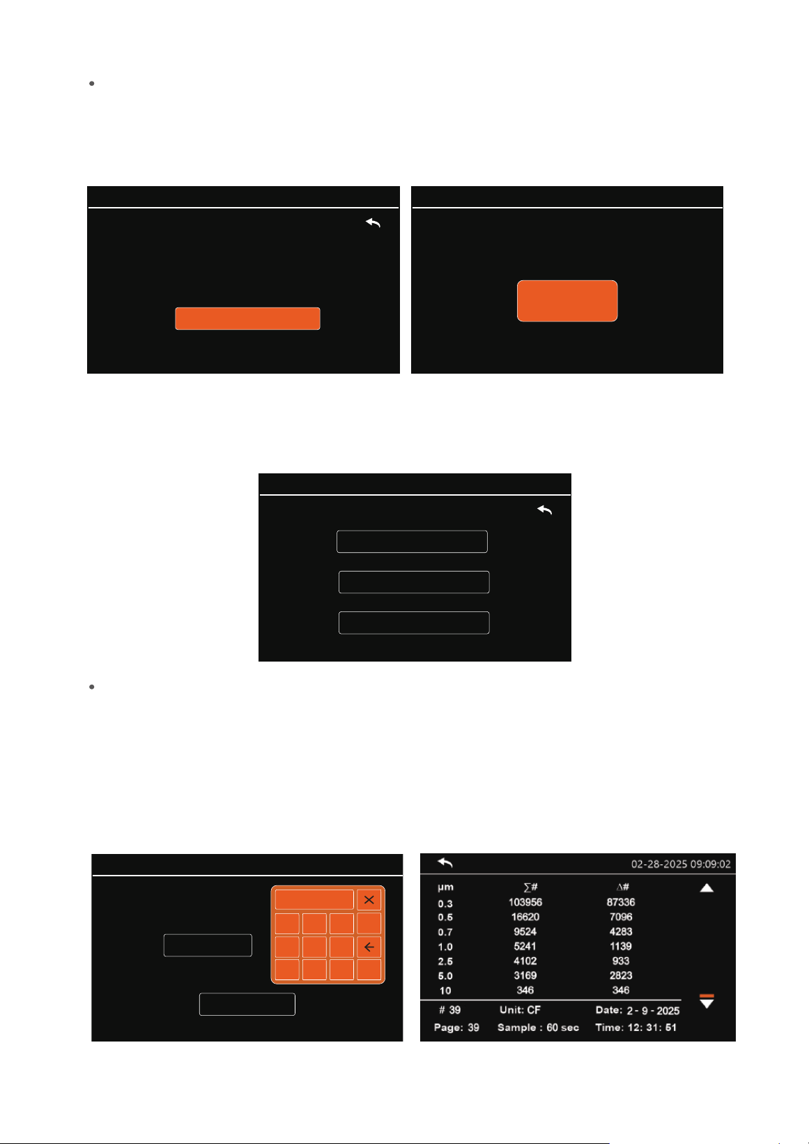
3.2.3 Data History
MENU->History:
History Deletion
Data Query
History Download
02-28-2025 09:09:02
In the Data History screen, you can perform data query, history download and history delete
operations (Fig. 20).
Fig. 20
Data Query
Click on ‘Data Query’ to enter the data query screen.
In the data query screen, the data stored in the device will be displayed by month. The system
automatically recommends the current month. If you need to look up the data for other months,
click the position where the month or year is located and the page will pop up the orange data
keyboard window.
Click the number to be entered on the keyboard and then click ‘OK’ to confirm.
After completing the settings, click ‘Query’ to query the data (Fig. 21).
MENU->History->Query:
Query
04 - 2025Month:
02-28-2025 09:09:02
1 2 3
4 5 6
7 8
9
0
OK
Fig. 21
Flow Calibration
MENU->Calibration->Flow:
Start Calibration
Press the Start Calibration button to calibrate
the flow.
02-28-2025 09:09:02
MENU->Calibration->Flow:
Flow Calibrating...
180
02-28-2025 09:09:02
Fig. 19

PMS 21 Remote Particle Counter User Manual
Page 12
By month
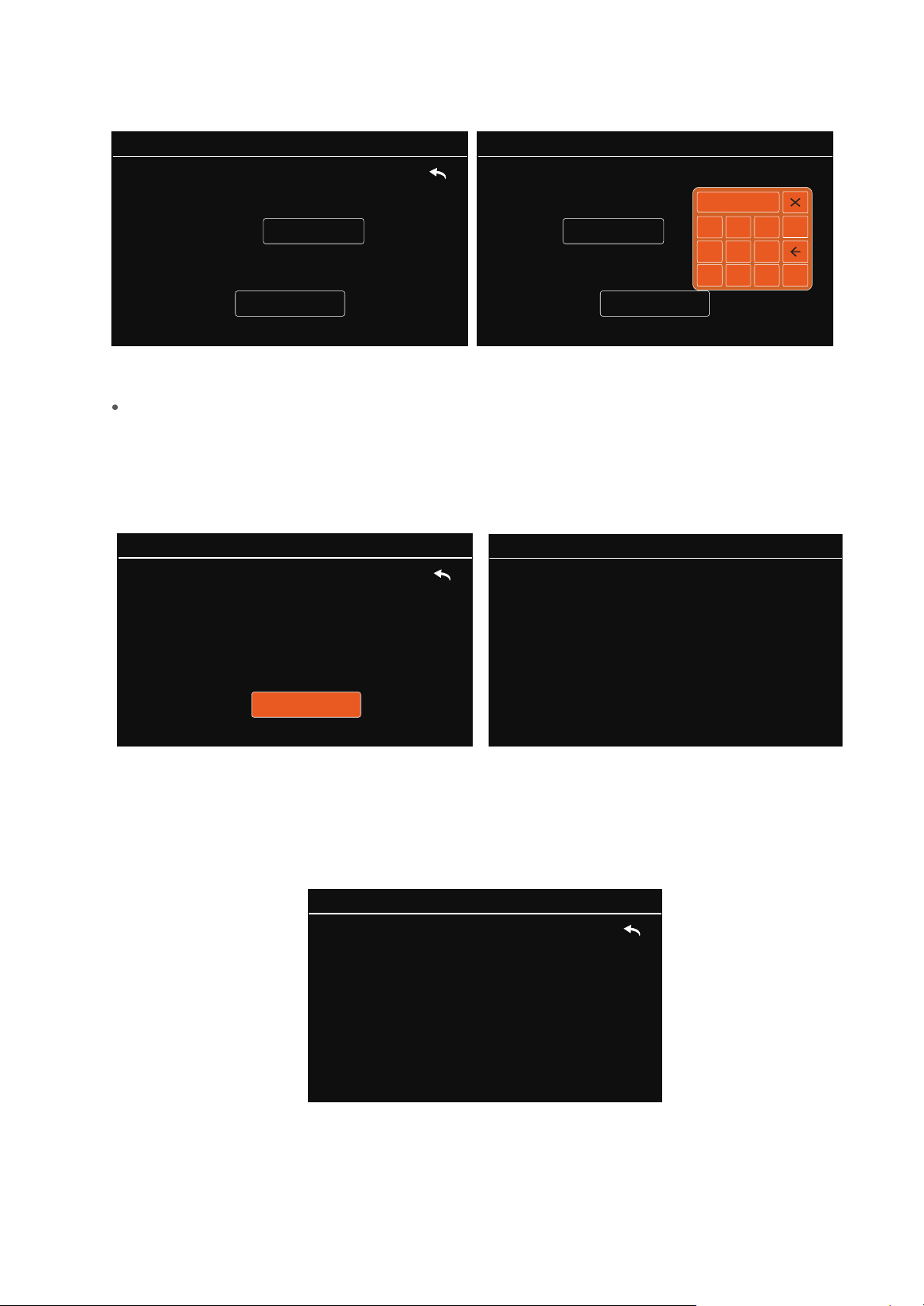
Click ‘By Month’ to enter the Delete by Month interface.
In the Delete by Month screen, by default, the system automatically recommends the current month.
If you need to delete other months data, click the position where the month or year is located, and the
page will pop up the orange data Keyboard window.
If no device is connected, it prompts no device, if the device is detected normally, it prompts
download success after the data download is completed.
After the data download is complete, unplug the USB device and plug the USB into the computer.
You will find a folder named ‘TEMTOP’, where users can view and analyse the data by themselves
(Fig. 23).
The USB device connection is faulty
or not detected.Please try agin later.
Succeeded !
Fig. 23
History Deletion
In the History Delete screen, you can perform Delete by Month and All Data operations (Fig. 24).
MENU->History->Delete:
By month
All Data
02-28-2025 09:09:02
Fig. 24
02-28-2025 09:09:02 02-28-2025 09:09:02
Fig. 22
History Download
In the data history interface, insert a USB device such as a USB stick or card reader into the USB port
of the instrument and click ‘History Download’. The system will check the connection status of the
USB device (Fig. 22).
Generating report, please wait.....
02-28-2025 09:09:02
MENU->History->Delete->Month:
Delete
04 - 2025
Month:
02-28-2025 09:09:02
MENU->History->Delete->Month:
Delete
04 - 2025
Month:
02-28-2025 09:09:02
1 2 3
4 5 6
7 8
9
0
OK
Fig. 25
All Data
Click ‘All Data’ to enter the interface to delete all data.
The interface will prompt to confirm the deletion of all information, click ‘Confire Delete’. And wait
patiently. After the deletion is completed, the screen will prompt to automatically return to the menu
interface (Fig. 26).
MENU->History->Delete->All:
Confire Delete
Are you sure you want to delete the data?
02-28-2025 09:09:02
Succeeded !
02-28-2025 09:09:02
Fig. 26
PMS 21 Remote Particle Counter User Manual
Page 13
3.2.4 System Information
Click ‘System Information’ to enter the system information interface, where you can view the model,
serial number, firmware version, brand, tel, and other information (Fig. 27).
Fig. 27
Model:PMS 21
Serial Number: XXXXXXXXXXXX
Firmware Version: VX.XX
Brand: Temtop
TEL:(+1)408-898-2866
MENU->
Information
:
02-28-2025 09:09:02
3.3 Power OFF
After disconnecting the power supply, the instrument switches o.
Click the number to be entered on the keyboard, and then click ‘OK’ to confirm.
After completing the settings, click ‘Delete’ to delete the data (Fig. 25).

PMS 21 supports two communication modes: RS-485 and USB.
RS-485 serial communication is used for real-time interaction.
USB communication is used to export data history.
The PMS 21 is based on the Modbus RTU protocol.
Only the master can initiate communication, as the PMS 21 is a slave and will not initiate
communication.
Any message(packet) starts with a silent interval of 3.5 characters. Another silent interval
of 3.5 characters marks message end.Silence interval between characters in the message
needs to be kept less than 1.5 characters.
Both intervals are from the end of Stop-bit of previous byte to the beginning of the
Start-bit of the next byte.
PMS 21 has 4 main data tables (addressable registers) that can be overwritten:
Discrete inputs (read-only bits)
Coils (read/write bits)
Input register (read-only16-bit word, interpretation depends on application)
Holding register (read / write 16-bit word)
Note: The sensor does not support bit-wise access to registers.
1. Input registers and holding registers are not allowed to overlap;
2. Bit-addressable items (i.e., coils and discrete inputs) are not supported;
3. The total number of registers is limited: The input register range is 0x03~0x10, and
the holding register range is 0x04~0x06, 0x61~0x69.
4. Alarm Value Unit: m³.
4. Protocols
4.1 RS-485 Serial Communication
Description
1) Master-Slave:
2) Packet icentificatior:
The maximum packet supported by the PMS 21 (serial line PDU, including address byte and
2-byte CRC) is 21 bytes.
3) Packet length:
4) Modbus Data Model:
4.1.1 Register List
Restrictions:
PMS 21 Remote Particle Counter User Manual
Page 14

PMS 21 Remote Particle Counter User Manual
Page 15
The register map (all registers are 16-bit words) is summarized in the table below.
0x00 N/A
N/A
N/A
Reserved
0x01
0x02
0x03 0.3µm Hi 16 Particles
Particles
Particles
Particles
Particles
Particles
Particles
Particles
Particles
Particles
Particles
Particles
Particles
Particles
0x04 0.3µm Lo 16
0x05
0.5µm Hi 16
0x06 0.5µm Lo 16
0x07 0.7µm Hi 16
Reserved
Reserved
0x0A
0x0B
0x0C
0x0D 5.0µm Hi 16
0x0E 5.0µm Lo 16
0x0F
10µm Hi 16
0x10
10µm Lo 16
0x08
0x09
0.7µm Lo 16
1.0µm Hi 16
1.0µm Lo 16
2.5µm Hi 16
2.5µm Lo 16
Holding Register List
0x06
0x07
0x08
0x09
0x0A
0x0B
0x0C
0x0D
0x0E
0x0F
0x10
0x11
0x12
0x13
0x00
0x01
1~247
0x00: Stop Detection
Year
Month
Day
Hour
Minute
Second
0x00:∑ 0x01:△
0x00:TC 0x01:CF 0x02:L 0x03:M
3
Sample Time
HOLD Time
Alarm Value
Alarm Value
Modbus Address
Stop Detection
Menu password Hi 16
Menu password Lo 16
Year
Month
Day
Hour
Minute
Second
Counting mode
Sample Unit Setting
Sample Time Setting
HOLD Time Setting
Alarm 0.3µm Hi 16
Alarm 0.3µm Lo 16
Input Register List
No.
Meaning Description
No.
Meaning Description
6-digit password

PMS 21 Remote Particle Counter User Manual
Page 16
0x14
0x15
0x16
0x17
0x18
0x19
0x1A
0x1B
0x1C
0x1D
0x1E
0x1F
0x20
0x21
0x22
0x23
0x24
0x25
Alarm Value
Alarm Value
Alarm Value
Alarm Value
Alarm Value
Alarm Value
Alarm Value
Alarm Value
Alarm Value
Alarm Value
Alarm Value
Alarm Value
Serial Number 0
Serial Number 1
Serial Number 2
Serial Number 3
Serial Number 4
Serial Number 5
Alarm 0.5µm Hi 16
Alarm 0.5µm Lo 16
Alarm 0.7µm Hi 16
Alarm 0.7µm Lo 16
Alarm 1.0µm Hi 16
Alarm 1.0µm Lo 16
Alarm 2.5µm Hi 16
Alarm 2.5µm Lo 16
Alarm 5.0µm Hi 16
Alarm 5.0µm Lo 16
Alarm 10.0µm Hi 16
Alarm 10.0µm Lo 16
Serial Number
Serial Number
Serial Number
Serial Number
Serial Number
Serial Number
0x06: Write a single holding register
0x10: Write multiple holding register
The remaining Modbus function codes are not supported for the time being.
0x03: Read holding register
0x04: Read input register
PMS 21 supports the following function codes:
4.1.2 Function Gode Description
4.1.3 Serial Setting
Baud rate: 9600,19200,115200(see 3.2.1 System Setting-COM Setting)
Data bits:8 Stop bit:1 Check bit: N/A
The sensor address is 0xFE.
The following uses ‘OxFE’ as an example.
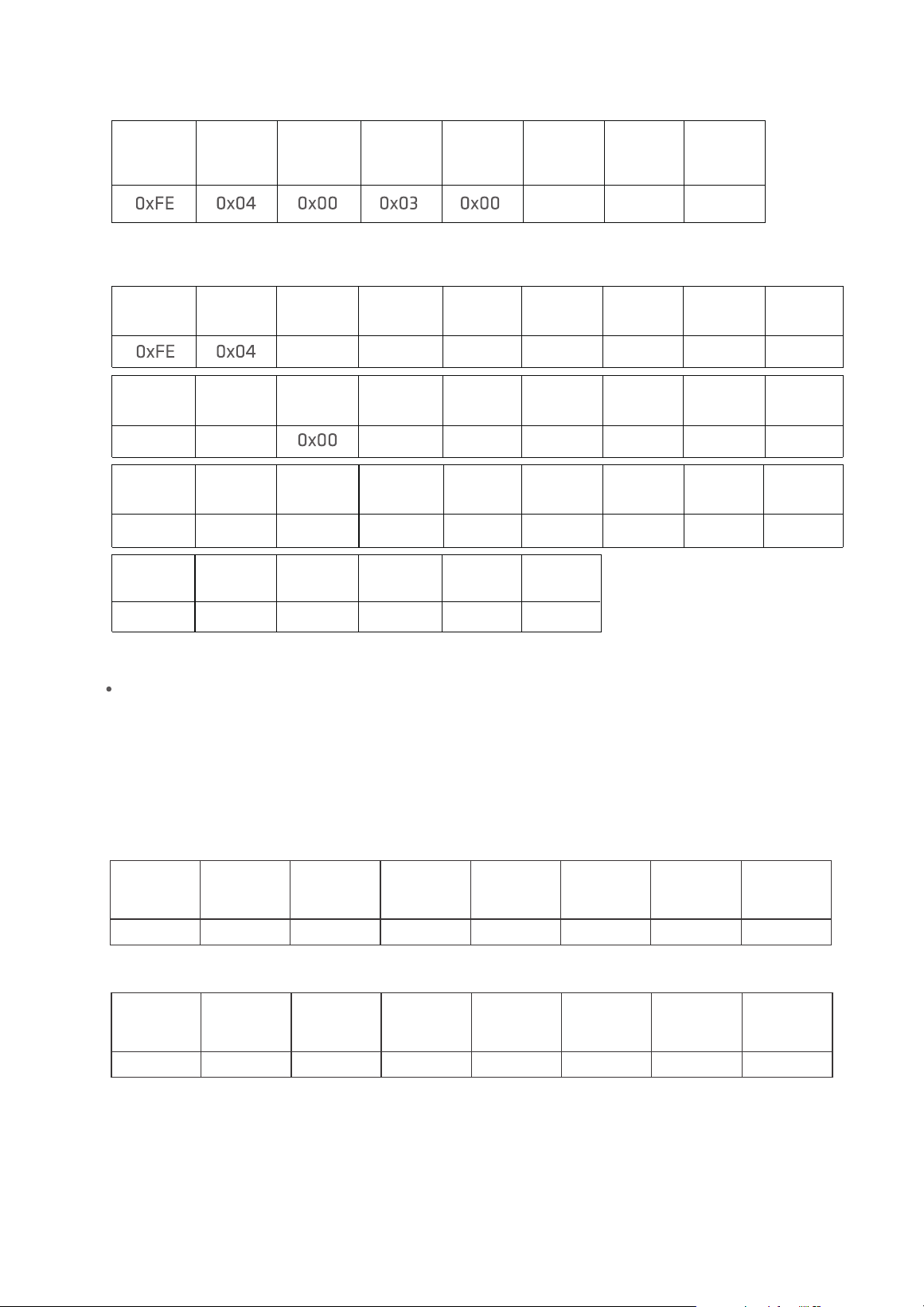
Use 0x04 (read input register) in Modbus to obtain detected data.
The detected data is put in a register with a starting address of 0x03, the number of registers
is 0x0E, and the CRC check is 0x95C1.
4.1.4 Application Example
Read Detected Data
0x0E
0xC1
0x95
Slave
Address
Function
Code
Starting
Address
Hi
Starting
Address
Lo
Quantity
Hi
Quantity
Lo
CRC16
Hi
CRC16
Lo
The master sends:
1.0µm Hi
16 Hi
2.5µm Hi
16 Hi
5.0µmHi
16 Hi
0x00
0x34
0x00
0x34
0x00 0x08
0.5µm Lo
16 Hi
0.5µm Lo
16 Lo
0x34 0x24
0.7µm Hi
16 Hi
0.7µm Hi
16 Lo
0x02
0.7µm Lo
16 Hi
0.7µm Lo
16Lo
0x34 0x24
1.0µm Hi
16 Lo
1.0µm Lo
16 Hi
0x02
1.0µm Lo
16 Lo
0x24
2.5µm Lo
16 Lo
2.5µm Lo
16 Hi
2.5µm Hi
16 Lo
0x02
0x24
5.0µm Hi
16 Lo
5.0µm Lo
16 Lo
5.0µm Lo
16 Hi
0x00
0xE8
10.0µm Hi
16 Hi
0x00
0xF5
0x08
CRC16
Lo
CRC16
Hi
10.0µm Hi
16 Lo
10.0µm Lo
16 Hi
10.0µm Lo
16 Lo
0x00 0xE8 0xD3
0.3µm Lo
16 Lo
0.5µm Hi
16 Lo
0x00 0x24 0x02
0.5µm Hi
16 Hi
0x000x34
0.3µm Lo
16 Hi
0.3µm Hi
16 Lo
0x02
0x1C
0.3µm Hi
16 Hi
Function
Code
Quantity
Slave
Address
The slave responds:
PMS 21 Remote Particle Counter User Manual
Page 17
Slave
Address
0XFE 0X06 0X00 0X01 0X00 0X01 0X0D 0XC5
Function
Code
Starting
Address
Hi
Starting
Address
Lo
Value
Hi
Value
Lo
CRC16
Hi
CRC16
Lo
Slave
Address
0XFE 0X06 0X00 0X01 0X00 0X01 0X0D 0XC5
Function
Code
Starting
Address
Hi
Starting
Address
Lo
Value
Hi
Value
Lo
CRC16
Hi
CRC16
Lo
Start Detection
The sensor address is OxFE
Use 0x06 (write a single holding register) in Modbus to start the detection.
Write 0x01 to register 0x01 to start detection. The starting address is 0x01, and the
registered value is 0x01. CRC calculated as 0x0DC5, first sent in the low byte.
The master sends:
The slave responds:
Slave
Address
0XFE 0X06 0X00 0X01 0X00 0X00 0XCC 0X05
Function
Code
Starting
Address
Hi
Starting
Address
Lo
Value
Hi
Value
Lo
CRC16
Hi
CRC16
Lo
Slave
Address
0XFE 0X06 0X00 0X01 0X00 0X00 0XCC 0X05
Function
Code
Starting
Address
Hi
Starting
Address
Lo
Value
Hi
Value
Lo
CRC16
Hi
CRC16
Lo
Stop Detection
The sensor address is 0xFE.
Use 0x06 (write a single holding register) in Modbus to stop the detection.
Write 0x00 to register 0x01 to start detection. The starting address is 0x01, and the
registered value is 0x00. CRC calculated as 0xCC05, first sent in the low byte.
The master sends:
The slave responds:
PMS 21 Remote Particle Counter User Manual
Page 18
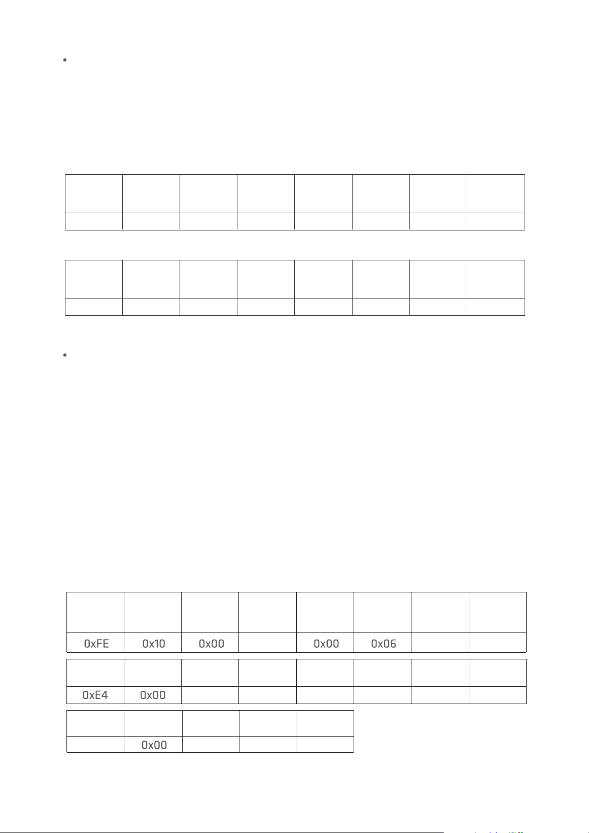
The sensor address is 0xFE.
Use 0x10 (write multiple holding registers) in Modbus to set the time.
In the register with start address 0x08, the number of registers is 0x06, and the number of
bytes is 0x0C, which respectively correspond to the year, month, day, hour, minute, and second.
Year is 0x07E4 (actual value is 2020)
Month is 0x0005 (actual value is May)
Day is 0x001D (actual value is 29th)
Houris 0x000D (actualvalue is 13),
Minute is 0x0018 (actual value is 24 minutes),
Second is 0x0000 (actual value is 0 seconds).
The CRC check is 0xC1BE.
0x08
0x00 0x1D 0x00 0x0D 0x00
0x18 0x00 0xBE0xC1
0x0C 0x07
0x05
Slave
Address
Function
Code
Starting
Address
Hi
Starting
Address
Lo
Value
Hi
Value
Lo
Byte
Count
Year
Hi
Year
Lo
Month
Hi
Month
Lo
Day
Hi
Day
Lo
Hour
Hi
Hour
Lo
Minute
Hi
Minute
Lo
CRC16
Lo
CRC16
Hi
Second
Hi
Second
Lo
Set Time
The master sends:
0xC6
0xD5
0x08
Please see 3.2.3 Data History - History Download for detail USB operations.
Slave
Address
Function
Code
Starting
Address
Hi
Starting
Address
Lo
Value
Hi
Value
Lo
CRC16
Hi
CRC16
Lo
The slave responds:
4.2 USB Communication
PMS 21 Remote Particle Counter User Manual
Page 19
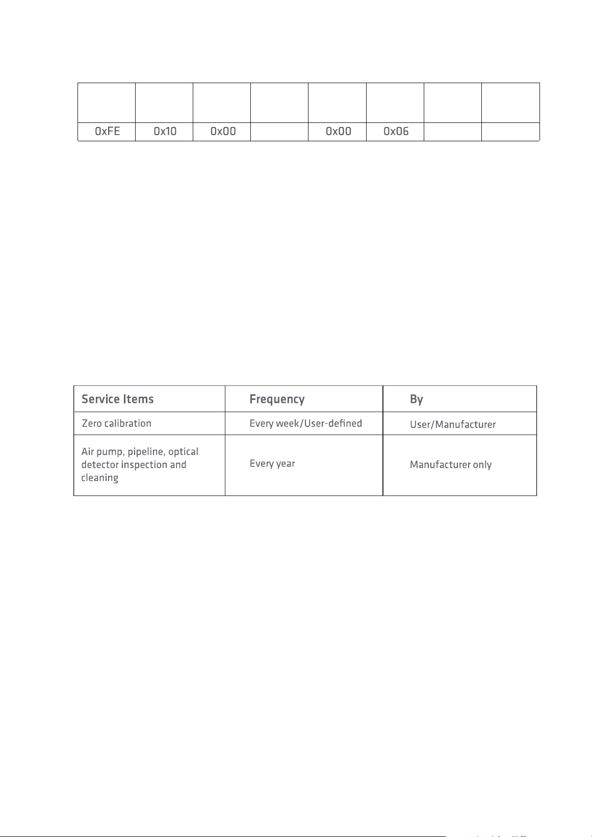
To make better use of PMS 21, regular maintenance is required in addition to correct operation.
Temtop recommends the following maintenance plan:
5. Maintenance
5.1 Maintenance Schedule
5.2 Zero Galibration
After the instrument has been used for a long time or the operating environment has been
changed, the instrument should be zero-calibrated. Regular calibration is required, and the
matching filter should be used for calibration by the following steps:
After the filter installed, open the Zero Calibration interface and refer to 3.2.2 System
Calibration-Zero Calibration for operation, After the calibration completed, remove the
filter and screw the filter cover back. When calibration is complete, remove the filter and
screw on the filter cover to complete the operation.
PMS 21 Remote Particle Counter User Manual
Page 20
It is recommended to return PMS 21 to the manufacturer for annual calibration by specialized
maintenance personnel in addition to weekly or monthly calibration by users.
Annual return-to-factory maintenance also includes the following preventative items to
reduce accidental failures:
5.3 Annual Maintenance
Check and clean the optical detector;
Check air pumps and pipes;
Replace the filter element
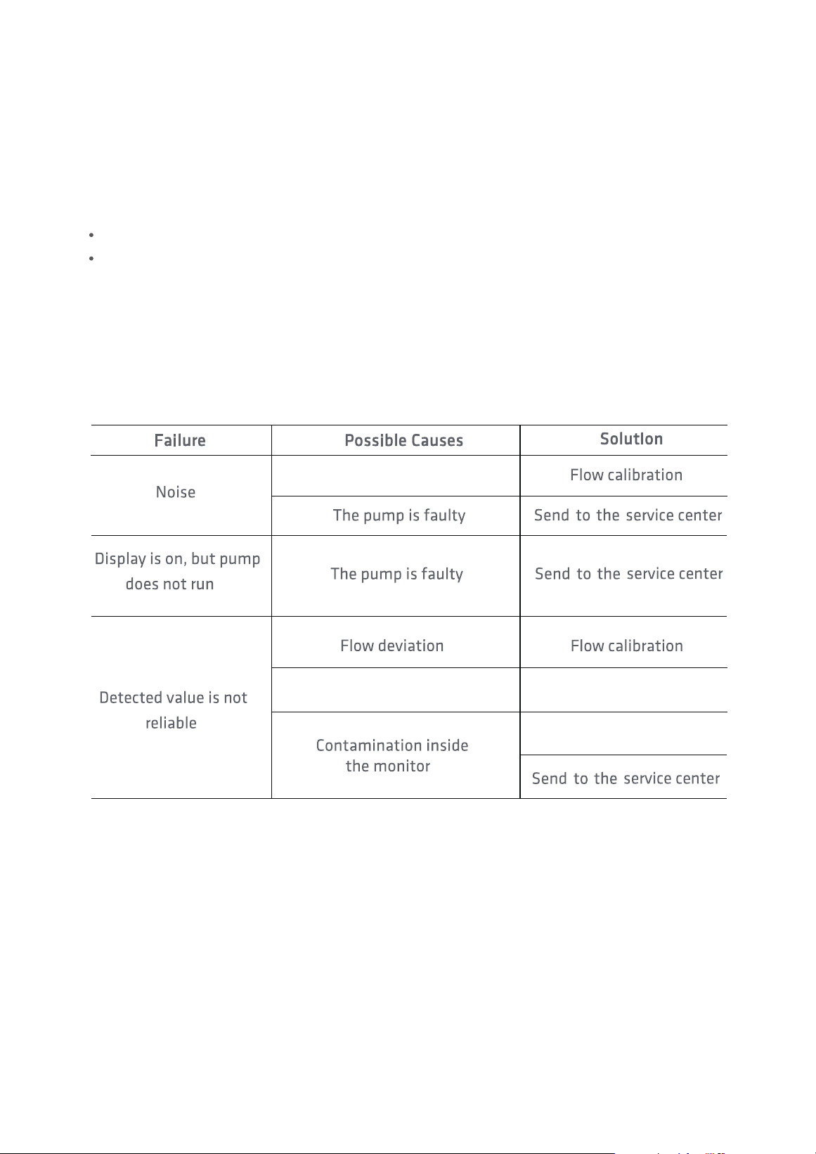
The flow is excessive
Inlet screen clogged
Check the inlet screen
6. Troubleshooting

7. Specifications
PMS 21 Remote Particle Counter User Manual
Page 21
Particle Diameter
0.3µm, 0.5µm, 0.7µm, 1.0µm,
2.5µm, 5.0µm, 10µm
Measurement
Range
3,000,000 CF
Accuracy
Principle
Light Source
Sampling Time
Hold Time
Flow
Display
Communication
Memory
±10%
0perating
Temperature
Storage
Temperature
Weight
Monitor
Dimensions
Light scattering technique
50mW,780nm
10-3600s
0,6-9999s
2.83 L/min
5.0" Touch
USB/RS-485
8,000,000 readings
0~50°C
-20~60°C
Excluding the air inlet (outlet) pipe
Both detection and display
Calibrate aerosol
Error +5%
192*135*82.5mm
2.5kg
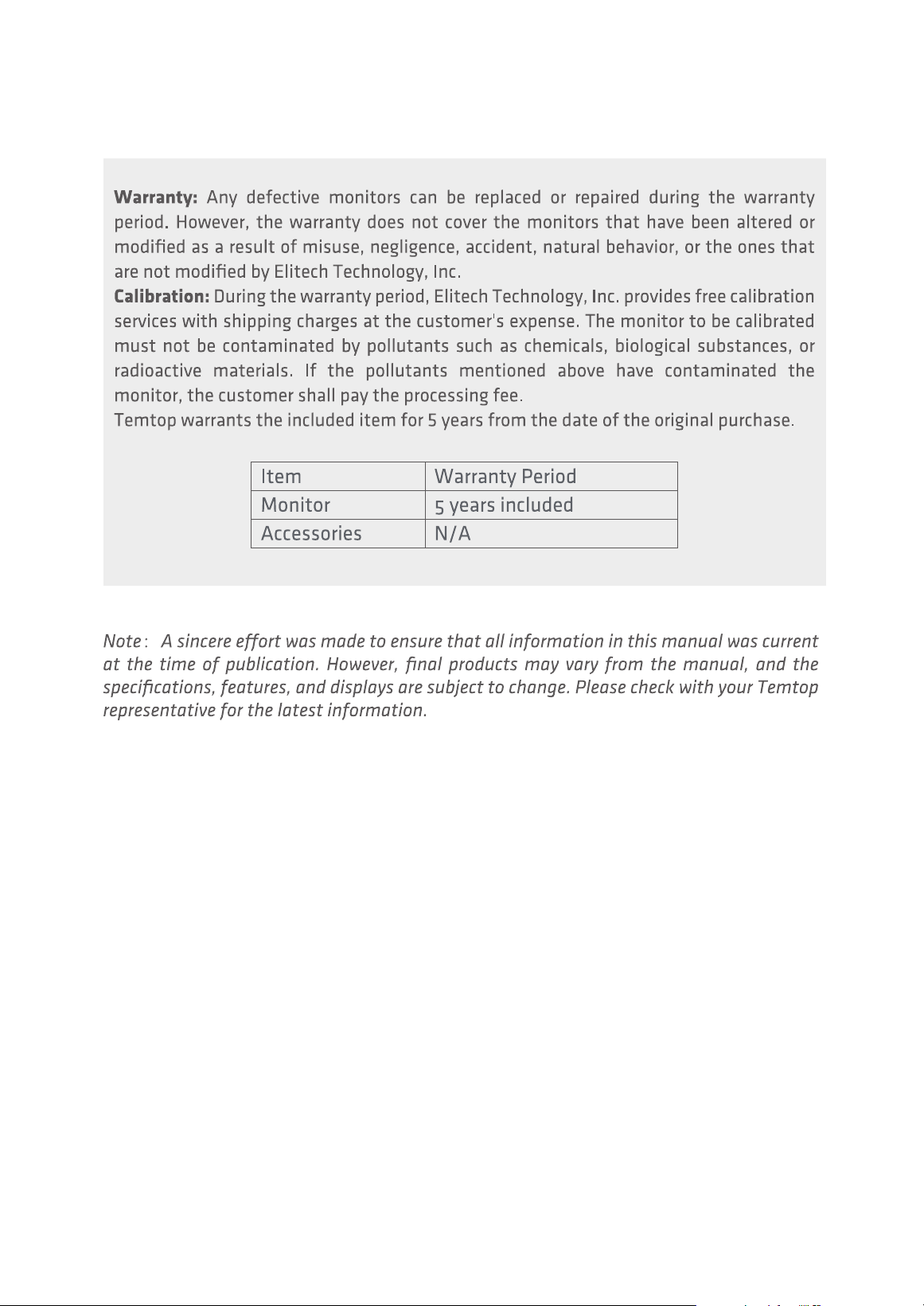
8. Warranty & Services
PMS 21 Remote Particle Counter User Manual
Page 22

V1.0
Made in China
Elitech Technology, Inc
2528 Qume Dr, Ste 2
San Jose, CA 95131 USA
Tel: (+1) 408-898-2866
Facebook: www.facebook.com/temtopus
Instagram: www.instagram.com/temtopaqm/
youtube: www.youtube.com/@Temtopus
linkedin: www.linkedin.com/company/temtop-us/
X: x.com/temtopus48285
Sales: [email protected]
Website: www.temtopus.com
Elitech Brazil Ltda
R.Dona Rosalina,90-Lgara, Canoas-RS
92410-695,Brazil
Tel: (+55)51-3939-8634
Sales: [email protected]
Website: www.elitechbrasil.com.br
Elitech (UK) Limited
Unit 13 Greenwich Business Park,
53 Norman Road,London, SE10 9QF
Tel: (+44)208-858-1888
Youtube: @elitech_uk
Instagram:@elitechuk_
Facebook: @hvaccontrol
Sales:[email protected]
Website: www.temtop.co.uk
Temtop (Shanghai) Technology Co., Ltd
Room 555 Pudong Avenue,
Pudong New Area, Shanghai,China
Tel: (+86)400-996-0916
Email:[email protected]
Website:www.temtopus.com