
v. 4.1#
SDP-75
3D SURROUND PROCESSOR
USER MANUAL

1

2
SDP-75 USER GUIDE
Software version v4.0
Last update: August 2, 2017


4
NOTICES
LIABILITY
The legal guarantees of conformity and latent defects under no circumstances cover any damage arising from accidents,
misuse or an assembly error, negligence or considerable modification of the appearance or functioning of the returned
equipment.
JBL Synthesis reserves the right to refuse any guaranteed return for a damaged product on account of misuse.
I. Acknowledgments
DTS® is a registered trademark of DTS, Inc.
Dolby® is a registered trademark of Dolby Laboratories.
Auro-3D® is a registered trademark of Auro Technologies.
All other trademarks are the properties of their respective owners.
The SDP-75 is manufactured under license from Dolby Laboratories. “Dolby”, “Dolby TrueHD”, “Dolby Atmos” and the
Double-D symbol are registered trademarks of Dolby Laboratories. License Notice and Trademark Acknowledgment
Required for Licensed Products Manufactured under license from Dolby Laboratories. Dolby, Dolby Atmos, Dolby
Surround, and the Double-D symbol are trademarks of Dolby Laboratories.
For DTS patents, see http://patents.dts.com. Manufactured under license from DTS Licensing Limited. DTS, the Symbol,
DTS in combination with the Symbol, DTS:X, and the DTS:X logo are registered trademarks or trademarks of DTS, Inc. in
the United States and/or other countries. © DTS, Inc. All Rights Reserved.
The SDP-75 is manufactured under license from Auro Technologies. BL Synthesis is certified by Auro Technologies to
implement its technology and products. Auro-3D® and the related symbols are registered trademarks of Auro
Technologies. All materials contained in this work are protected by copyright law and may not be reproduced, distributed,
transmitted, displayed, published or broadcast without the prior written permission of Auro Technologies NV or in case
of third party materials, the owner of that content. You may not alter or remove any trademark, copyright or other notice
from copies of the content.
©2003-2016 JBL Synthesis. All rights reserved.
Due to constant improvement, all products specifications and design may change without notice.
Photos and illustrations are non-contractual.

5
IMPORTANT SAFETY
INSTRUCTIONS
• Read the following instructions carefully. Save all instructions for future reference.
• Follow all warnings and instructions.
• JBL Synthesis expressly forbids unauthorized modification of this equipment.
• Using the unit in the following locations can result in a malfunction:
o In direct sunlight
o Locations of extreme temperature or humidity
o Excessively dusty or dirty locations
o Locations of excessive vibration
o Close to magnetic fields
• Condensation can form on the inside of the apparatus if it is suddenly moved from a cold environment to a
warmer location. Before switching the unit on, it is recommended that the unit be allowed to reach room
temperature.
• Install the SDP-75 on a solid, flat, level surface that is dry, well ventilated and out of direct sunlight. Be sure
that all four feet are supported.
• • Clean only with a dry cloth. Do not use liquid solvent-based cleaners.
• Protect the detachable power cord from being walked on or pinched particularly at plugs, convenience
receptacles, and the point where they exit from the apparatus. If the ac cord becomes damaged, do not use it.
Immediately replace it with a new one of the same or better rating.
• Unplug this apparatus during lightning storms or when unused for long periods of time.
• Do not open the equipment case or remove any of the cover panels. There are no user serviceable parts in this
equipment. Refer all servicing to qualified service personnel;
• To prevent fire or shock hazard, do not allow liquids to spill or objects to fall into any openings of the product.
• Always insert the ac plug into a grounded outlet. Do not remove the ground pin or disable the ground for any
purpose. The main AC has to be protected by a circuit breaker conforming to local standards.
• Before connecting the equipment, check that the main power supply voltage rating corresponds with the local
main power supply. The rating of the main power supply voltage is printed on the equipment.
• If replacement of the ac line fuse and/or any internal fuse becomes necessary, replace only with same value
and type of fuse (110V: T1A Schurter FST 5x20; 220V: T800mA Schurter FST 5x20). Never bypass the fuse.
• It is imperative that the SDP-75 be operated in a well ventilated environment and the immediate external
temperature be maintained as specified. Do not expose the SDP-75 to humidity, steam, smoke or excessive
dampness or dust. Maximum permissible operating conditions: 0°C to 40°C, 20-65% relative humidity. External
cooling fans may be required in some cases.
• Do not stack any equipment directly above or below the SDP-75 as to protect it from overheating, as well as
the continued functionality of any equipment near and around it.
• Do not ingest the remote control battery. The remote control supplied with this product contains a coin battery.
If the button cell battery is swallowed, it can cause severe internal burns in just 2 hours and can lead to death.
Keep new and used batteries away from children. If the battery compartment does not close securely, stop
using the product and keep it away from children. If you think batteries might have been swallowed or placed
inside any part of the body, seek immediate medical attention.
TO COMPLETELY DISCONNECT THIS APPARATUS FROM THE AC MAINS, DISCONNECT THE POWER SUPPLY
CORD PLUG FROM THE AC RECEPTACLE.
THIS SYMBOL IS INTENDED TO ALERT THE USER TO THE PRESENCE OF UNINSULATED "DANGEROUS
VOLTAGE" WITHIN THE PRODUCT'S ENCLOSURE THAT MAY BE SUFFICIENT MAGNITUDE TO
CONSTITUTE A RISK OF ELECTRIC SHOCK.
6
TABLE OF CONTENTS
NOTICES .................................................................................................................................................. 4#
IMPORTANT SAFETY INSTRUCTIONS .................................................................................................... 5#
TABLE OF CONTENTS ............................................................................................................................. 6#
1# INTRODUCTION ............................................................................................................................ 10#
1.1# ABOUT THIS GUIDE ................................................................................................................... 11#
1.2# PRODUCT INFORMATION ............................................................................................................ 13#
1.3# SYSTEM INTEGRATION ............................................................................................................... 14#
1.4# JBL SYNTHESIS CERTIFIED INSTALLERS ................................................................................... 14#
1.5# UNPACKING THE SDP-75 ......................................................................................................... 15#
1.6# THE HARDWARE ....................................................................................................................... 16#
# Front panel layout ..................................................................................................................................... 16#
# Front panel display ................................................................................................................................... 16#
# Rear panel layout ...................................................................................................................................... 17#
# IR remote control ...................................................................................................................................... 18#
1.7# THE SOFTWARE ........................................................................................................................ 19#
# Available options to access the graphical user interface ......................................................................... 19#
# Important note about the web-based interface ........................................................................................ 20#
# Using a display, mouse and keyboard connected to the SDP-75 ............................................................. 20#
# The Top menu bar ..................................................................................................................................... 21#
# The Main user interface ............................................................................................................................ 22#
# The Lateral menu bar ................................................................................................................................ 22#
# Folded lateral menu .................................................................................................................................. 23#
# Unfolded lateral menu .............................................................................................................................. 24#
# The Speakers/Room setup tool ................................................................................................................ 25#
# The Fine Tuning panel .............................................................................................................................. 25#
# The Advanced Settings interface .............................................................................................................. 26#
# Product Information .................................................................................................................................. 26#
# Software updates ...................................................................................................................................... 27#
2# NETWORK SETUP ......................................................................................................................... 28#
2.1# CHOOSING A NETWORK CONFIGURATION ....................................................................................... 28#
2.2# CONNECTING TO THE SDP-75 ................................................................................................... 29#
# Overview of the network connection procedure ....................................................................................... 29#
# Step 1: download and install a VNC client on your device ........................................................................ 30#
# Step 2: put the SDP-75 and your device on the same network ................................................................ 31#
# Step 3: connect to the SDP-75 from your device ..................................................................................... 35#
# Using a Mac OS X computer with Screen Sharing .................................................................................... 36#
# Using a Mac OS X computer with Chicken of the VNC ............................................................................. 37#
# Using a Windows computer with Tight VNC ............................................................................................. 38#
2.3# CHANGING THE NETWORK SETTINGS THROUGH THE FRONT PANEL .................................................... 41#
# Checking the Wi-Fi settings ...................................................................................................................... 41#
# Checking the Ethernet settings ................................................................................................................. 42#
# Connecting the SDP-75 to a Wi-Fi network .............................................................................................. 42#
2.4# CHANGING THE WI-FI SETTINGS THROUGH THE GUI ...................................................................... 43#
# About the Wi-Fi information ..................................................................................................................... 43#
# Checking the Wi-Fi settings ...................................................................................................................... 43#
# Connecting the SDP-75 to a Wi-Fi network .............................................................................................. 44#
# Changing the Wi-Fi Status mode of the SDP-75 ...................................................................................... 45#
2.5# CHANGING THE ETHERNET SETTINGS THROUGH THE GUI ................................................................ 46#
# About the Ethernet information ................................................................................................................ 46#
# Checking the Ethernet settings ................................................................................................................. 46#
# Changing the Ethernet Settings ................................................................................................................ 47#
2.6# ABOUT VNC AND ZERO-CONF NETWORKING ................................................................................. 48#
# About VNC (Virtual Network Computing) .................................................................................................. 48#
# About zero-configuration networking ...................................................................................................... 48#
3# NETWORK STREAMING ................................................................................................................ 49#

7
3.1# THE UPNP PROTOCOLE ............................................................................................................ 49#
3.2# UPNP NETWORK ARCHITECTURE ................................................................................................ 49#
3.3# RECOMMENDED UPNP SOFTWARE ............................................................................................... 50#
4# DAILY OPERATIONS ..................................................................................................................... 52#
4.1# AVAILABLE USER INTERFACES ..................................................................................................... 52#
4.2# USING THE FRONT PANEL ........................................................................................................... 53#
# Power On-Off Sequence ........................................................................................................................... 53#
Volume control ......................................................................................................................................................... 54#
Source selection ...................................................................................................................................................... 54#
Preset selection ....................................................................................................................................................... 54#
# Checking the format of incoming audio ................................................................................................... 55#
4.3# USING THE IR REMOTE CONTROL ................................................................................................. 56#
# Volume control ......................................................................................................................................... 56#
# Source selection ....................................................................................................................................... 56#
# Listening format Selection ........................................................................................................................ 56#
# Presets selection ...................................................................................................................................... 57#
# Access to the Front Panel menu ............................................................................................................... 57#
# Light Button .............................................................................................................................................. 57#
# Level and Delay Adjustment Bypass ........................................................................................................ 57#
4.4# USING THE GRAPHICAL INTERFACE .............................................................................................. 58#
# Volume control ......................................................................................................................................... 58#
# Source selection ....................................................................................................................................... 58#
# Preset selection ........................................................................................................................................ 59#
# Checking the format of incoming audio ................................................................................................... 59#
5# BASIC SETTINGS .......................................................................................................................... 60#
5.1# NAMING YOUR SOURCES ............................................................................................................ 60#
5.2# CONFIGURING YOUR SOURCES .................................................................................................... 61#
5.3# DEFAULT SOURCE CONFIGURATION .............................................................................................. 63#
5.4# LEVEL AND DELAY ALIGNMENT OPTIONS ...................................................................................... 64#
5.5# NAMING, SAVING AND LOADING PRESETS ...................................................................................... 65#
5.6# DEFAULT PRESET ..................................................................................................................... 66#
5.7# SET A MAXIMUM VOLUME ......................................................................................................... 67#
5.8# SET THE DIM LEVEL .................................................................................................................. 68#
5.9# BACKUP/RESTORE OF PRESETS .................................................................................................. 68#
6# OVERVIEW OF THE SETUP PROCEDURE ...................................................................................... 70#
7# ESSENTIAL TOOLS AND SETTINGS .............................................................................................. 71#
7.1# AUDIO CLOCK SETTINGS ............................................................................................................ 71#
# Audio clock status information ................................................................................................................. 71#
# Audio clock setup ..................................................................................................................................... 72#
7.2# METERING THE INPUTS AND OUTPUTS .......................................................................................... 73#
7.3# PLAYING PINK NOISE ON THE SPEAKERS ....................................................................................... 74#
7.4# SOLO/MUTE AN INPUT OR AN OUTPUT ......................................................................................... 75#
7.5# SWITCHING LEVEL AND DELAY ADJUSTMENTS ON/OFF ................................................................... 76#
7.6# VIEWING THE ACOUSTICAL GRAPHS ............................................................................................. 77#
# Important notes ........................................................................................................................................ 78#
# Graphs display options ............................................................................................................................. 78#
# Choose display options according to your requirements ......................................................................... 79#
8# SPECIFY THE SPEAKER LAYOUT ................................................................................................. 81#
8.1# OVERVIEW OF THE SPEAKERS SETUP PROCEDURE ........................................................................... 81#
8.2# INTRODUCING THE SPEAKER/ROOM SETUP TOOL ........................................................................... 81#
8.3# AN EXAMPLE OF A SPECIFIC SPEAKER LAYOUT ............................................................................... 83#
8.4# AVAILABLE INITIAL LAYOUTS ...................................................................................................... 84#
8.5# SELECT AN INITIAL SPEAKER LAYOUT ........................................................................................... 85#
8.6# ADDING SPEAKERS .................................................................................................................... 86#
# Adding Regular Speakers .......................................................................................................................... 86#
# Adding Dolby Enabled Upfiring speakers .................................................................................................. 87#
8.7# REMOVING SPEAKERS ................................................................................................................ 88#
8.8# CONFIGURE THE SETTINGS OF EACH SPEAKER ............................................................................... 88#
8.9# CONFIGURE THE CROSSOVER SETTINGS (OPTIONAL) ....................................................................... 90#
8.10# MAPPING THE CHANNELS OF DIFFERENT FORMATS ......................................................................... 90#
8
8.11# SEND PINK NOISE TO VERIFY THE ROUTING OF THE SPEAKERS ........................................................... 91#
8.12# SAVE THE PRESET ..................................................................................................................... 92#
9# SPECIFY AN ARRAY OF SPEAKERS .............................................................................................. 93#
9.1# SETTING UP AN ARRAY OF SPEAKERS ........................................................................................... 93#
9.2# EXAMPLE OF AN ARRAY OF SPEAKERS .......................................................................................... 94#
9.3# ADJUST THE GAIN ..................................................................................................................... 94#
9.4# SAVE THE PRESET .................................................................................................................... 95#
10# DECODER / UP-MIXER SETTINGS ................................................................................................ 96#
10.1# SUPPORTED DECODERS/UP-MIXERS ........................................................................................... 96#
10.2# LISTENING FORMATS ................................................................................................................ 97#
10.3# USING THE FRONT PANEL ......................................................................................................... 101#
Listening format selection ...................................................................................................................... 101#
Decoders Configuration .......................................................................................................................... 101#
10.4# USING THE GRAPHICAL INTERFACE ............................................................................................ 102#
Listening formats selection .................................................................................................................... 102#
Decoders Configuration .......................................................................................................................... 102#
10.5# DECODERS SETTINGS .............................................................................................................. 103#
General Settings ..................................................................................................................................... 103#
Dolby decoder settings ........................................................................................................................... 104#
DTS decoder Settings ............................................................................................................................. 105#
Auro-3D decoder settings ...................................................................................................................... 106#
11# GETTING READY FOR CALIBRATION .......................................................................................... 107#
11.1# VERY IMPORTANT TIPS ....................................................................................................... 107#
11.2# CHECKLIST BEFORE YOU START ................................................................................................. 107#
11.3# IMPORTANT RECOMMENDATIONS FOR MICROPHONE PLACEMENT .................................................... 108#
Requirements for the measurement environment .................................................................................. 108#
Reference measurement point ............................................................................................................... 108#
Position and orientation of the microphone for the reference point ...................................................... 108#
12# CALIBRATE THE ACTIVE CROSSOVERS (OPTIONAL) ................................................................. 110#
12.1# OVERVIEW OF THE CROSSOVER SETUP PROCEDURE ....................................................................... 110#
12.2# CONFIGURE THE ADVANCED SETTINGS (OPTIONAL) ....................................................................... 111#
12.3# ADJUST THE MASTER OUTPUT LEVEL ......................................................................................... 113#
12.4# CALIBRATE THE ACTIVE CROSSOVERS ......................................................................................... 114#
12.5# VERIFY THE SOUND OF THE CALIBRATED CROSSOVERS .................................................................. 115#
Visualize the acoustical graphs for each speaker .................................................................................. 115#
Listen to each speaker connected to the crossover ............................................................................... 117#
12.6# SAVE THE PRESET ................................................................................................................... 117#
13# LEVEL AND DELAY CALIBRATION .............................................................................................. 118#
13.1# OVERVIEW OF THE CALIBRATION PROCEDURE ............................................................................... 118#
13.2# ADJUST THE MASTER OUTPUT LEVEL ......................................................................................... 118#
13.3# NORMAL CALIBRATION SEQUENCE ............................................................................................. 119#
13.4# COMMON PROBLEMS DURING CALIBRATION ................................................................................ 120#
13.5# CALIBRATION STATUS ............................................................................................................. 120#
13.6# CHECKING THE SPEAKER SUMMARY AFTER CALIBRATION ............................................................... 121#
13.7# MULTI-POINT MEASUREMENTS (OPTIONAL) ................................................................................ 124#
13.8# COMPUTE THE OPTIMIZATION FILTERS ....................................................................................... 124#
13.9# SAVE THE PRESET ................................................................................................................... 125#
14# SETUP BASS MANAGEMENT ...................................................................................................... 126#
14.1# OVERVIEW OF THE BASS MANAGEMENT SETUP PROCEDURE ............................................................ 126#
14.2# FULLY CUSTOMIZABLE BASS MANAGEMENT ................................................................................ 127#
14.3# BASS MANAGEMENT MODE ....................................................................................................... 128#
14.4# QUICK SETUP MENU ................................................................................................................ 130#
Set Filters ................................................................................................................................................ 131#
Apply to selected speakers ..................................................................................................................... 131#
14.5# BASS MANAGEMENT SETTINGS FOR INDIVIDUAL SPEAKER .......................................................... 132#
14.6# LFE & MISC .......................................................................................................................... 133#
Low Frequency Effect Setup ................................................................................................................... 133#
9
# +10 Db on LFE ......................................................................................................................................... 133#
# Stacked Sub Correction .......................................................................................................................... 134#
15# SETUP TARGET CURVES ............................................................................................................ 135#
15.1# OVERVIEW OF THIS PROCEDURE ................................................................................................ 135#
15.2# SETTING UP ONE OR MORE TARGET CURVES ................................................................................ 135#
16# VERIFY THE SOUND OF YOUR OPTIMIZED SPEAKER SYSTEM ................................................. 137#
16.1# VISUALIZE THE ACOUSTICAL GRAPHS FOR ALL SPEAKERS ............................................................... 137#
16.2# LISTEN TO THE SYSTEM ........................................................................................................... 138#
17# FINE TUNING OPTIMIZATION SETTINGS ................................................................................... 139#
17.1# MAIN OPTIMIZATION SETTINGS ................................................................................................. 139#
17.2# SPEAKER POSITION REMAPPING .................................................. ERROR! BOOKMARK NOT DEFINED.#
17.3# TARGET CURVE ...................................................................................................................... 141#
17.4# LIMITER CURVE ...................................................................................................................... 141#
17.5# ADVANCED OPTIMIZATION SETTINGS ......................................................................................... 142#
# Display .................................................................................................................................................... 142#
# Front & Surround Speaker settings ......................................................................................................... 142#
# Acoustics Correction .............................................................................................................................. 143#
# Calibration settings ................................................................................................................................. 143#
# Optimize according to L&R speakers settings ........................................................................................ 143#
# FIR and IIR settings ................................................................................................................................. 143#
# Level alignment settings ......................................................................................................................... 144#
# Subwoofer low-pass filter settings ........................................................................................................ 144#
# Decimation settings & Advanced FIR settings ........................................................................................ 144#
# Advanced FIR settings ............................................................................................................................ 144#
18# PERFORMING MULTI-POINT MEASUREMENTS ........................................................................ 145#
18.1# RELEVANT MEASUREMENT POSITIONS ........................................................................................ 146#
18.2# MULTI-POINT CALIBRATION PROCEDURE .................................................................................... 147#
18.3# WEIGHTING MULTIPLE MEASUREMENTS ...................................................................................... 147#
19# APPENDIX ................................................................................................................................... 148#
19.1# INSERT AN EXTERNAL STEREO DAC ........................................................................................... 148#
19.2# REMOTE START AND STOP ....................................................................................................... 148#
19.3# AUTOMATION ........................................................................................................................ 148#
19.4# SIGNAL FLOW OF THE SDP-75 ................................................................................................. 149#
# Setup Process and filters calculation ..................................................................................................... 149#
19.5# 3D SPEAKER PLACEMENT RECOMMENDATIONS ............................................................................ 149#
19.6# DB25 CONNECTOR: ANALOG PINOUT PINOUT ............................................................................. 150#
19.7# DB25 CONNECTOR : AES PINOUT ............................................................................................ 150#
19.8# 3D MEASUREMENT MICROPHONE .............................................................................................. 151#
# Microphone specifications ..................................................................................................................... 152#
# Power supply .......................................................................................................................................... 152#
# Individual compensation file ................................................................................................................... 152#
# Connection order .................................................................................................................................... 154#

10
1 INTRODUCTION
The JBL SDP-75 defines the state of-the-art in surround sound processors in terms of sound
quality, seamless "3D" immersive audio, true decoding of up to 32 channels* in Dolby Atmos,
seamless, optimized decoding and processing of all currently-available surround CODECs,
utilizing HARMAN's newest research-based on-board room correction. The SDP-75 is part of
a JBL Synthesis or Revel-based ecosystem, which optimizes numerous parameters based on
easy-to-use drop-down speaker model selections. #
Utilizing an Intel®i7 PC-based platform, only the JBL SDP-75 offers all these features,
as well as a future-resistant on-line update capability that no DSP-based system can match.
64-bit floating point calculations and 24-bit/192kHz native processing assures the highest
sound quality from virtually any source, and without re-clocking, which is the case for virtually
every other surround processor, and which results in a significant sonic compromise.
A user-friendly web-based interface for both setup, calibration and run-time operation
allows remote setup, operation and diagnoses via IP. An exclusive 3D speaker configuration
tool simplifies arraying speaker groups, optimization of speaker functionality based upon
codecs, and convenient channel identification. Internal gigabit Ethernet, and full host Wi-Fi
simplify setup and operation.
*16, 24, and 32-channel versions of the SDP-75 are available.

11
About this guide
This guide includes the most important information you need in order to use and setup the SDP-75 in your home theatre
system. From the most frequent daily operations to advanced calibration functionality, this document will guide you
through every step of the task you wish to accomplish.
This guide is organized in the following parts:
PART I: GETTING STARTED WITH THE SDP-75:
Introduction: unpacking the SDP-75 and an overview of the hardware and the software.
Network Setup: setting up the network to start using the software.
PART II: USING THE SDP-75 ON A DAILY BASIS IN YOUR HOME THEATRE:
Daily Operations: Explains how to perform simple operations such as power-on/power-off, volume control, source
selection, preset selection and decoder settings via the front panel, with the IR remote control or through the software
user interface.
Basic Settings: Explains how to name and configure your sources, how to switch on/off the level and delay alignment
options, how to manage presets, and how to backup/restore presets to/from a USB memory stick.
PART III: INTEGRATING THE SDP-75 IN YOUR HOME THEATRE SYSTEM:
Overview of the setup procedure: A summary of the main steps you must follow in order to successfully integrate the
SDP-75.
Essential tools and settings: Provides important information about the software tools and settings you need to know
before starting the setup process.
Specify the Speaker Layout: How to provide the SDP-75 with all the information about your set of speakers. This
information is required for the delay and level alignment of the speakers in the room.
Specify an Array of Speakers: Provides information to setup an array of speakers.
Decoder/Up-mixer Settings: Provides necessary information on the different decoders supported, their up-mixer and the
settings available.
Getting ready for delay and level alignment: Provides important tips and recommendations you need to know before
running the calibration procedure, including tips about microphone placement.
Setup Bass Management: Explains the advanced bass management options supported by the SDP-75.
ADDITIONAL INFORMATION ABOUT THE SDP-75
SURROUND PROCESSOR:
Appendix: Technical information about automation, the signal flow, the 3D speaker placement recommendations,
connector pinouts.
To improve clarity throughout this document, references to user interface items will be shown in bold letters and
illustration’s caption will be shown in italic bold letters.
This guide also includes information about the latest 3D formats and common practice in terms of speaker placement
to help you understand the new approach of 3D Sound in the best possible and least confusing way.
In addition, important information will be
indicated with the following symbols.
NOTE
IMPORTANT NOTE
Record of Changes:
Date
Software version

12
July 2016
Software version 4.0.10 – First Production Release
April 2017
4.1.x
IMPORTANT NOTE: The content of this document is subject to change without notice.

13
1.1 PRODUCT INFORMATION
MAIN FEATURES
• 16 or 32 Channel Digital Audio Processor
• Universal Spatial-Accurate 3D Audio
playback
• Best-in-class Room Optimization fully
integrated
• Superior multi-subwoofer management and
active crossovers calibration
• 118 digital and analog inputs + 80 audi
o
outputs
• 8x HDMI Inputs, 2x HDMI Outputs
• User-friendly, self-explaining user interface
• Built-in Wi-Fi & UPnP/DLNA Compliant Digital
Media Renderer
• Wide choice of Remote Options
EXCLUSIVE TECHNOLOGIES
SUPPORTED AUDIO/VIDEO FORMATS
• Trinnov Room Optimization
• Next Generation Hardware platform:
• Revolutionary architecture, scalable
processing platform
• 64 bits floating point & 24 bits / 192 kHz nativ
e
processing
• Future-resistant software-oriented upgrades
provided over internet, no DSP upgra
de
required
• Robust design, inspired from our professional
audio product lines
• High-performance AD/DA converters, us
ed
daily by the most demanding mastering studios
• LPCM Audio: 16-channels AES input compatible with
Digital Cinema Servers
• 3D Audio Codecs (optional): Auro-3D, Dolby Atmos
and DTS:X, including their respective up-mixers
• HD Audio Codecs: Dolby TrueHD, DTS-HD Master
Audio
• HDMI 1.4a compliant digital audio with 4K and 3D
video pass-through (HDCP 2.2 : HDMI input 1, HDMI
output 2)
• UPnP/DLNA renderer: WAV, AIFF, OGG, FLAC up to 24
bits / 192 kHz
SUBWOOFER MANAGEMENT
• Adjustable High-pass / Low-pass editable by
individual satellite/sub or by group of speakers
• Support from 0 to 32 subwoofers
• Automatic level and delay
REMOTE MANAGEMENT
• VNC Remote Control through the network from
any smartphone, tablet or laptop
• Web-based responsive interfa
ce
• Automation via Telnet and RS232 protocols
• Crestron, Savant, Control4 and AMX modules are
available
• Built-in Gigabit Ethernet and Wi-Fi
• IR remote control included
• 12V Trigger in/out
AUDIO PROCESSING
• Comprehensive Processing latency control
• Automatic Processing :
• Multi-point acoustic measurement
(Trinnov 3D measurement microphone)
• Time/Frequency acoustic analysis base
d
on impulse response measurement
• Loudspeaker/Room optimization
• Target Curves
• Manual Processing
• Several layers of 31 band Graphic EQ, FIR EQ, gains,
polarity and delay available for every channel.
• Total delay given in meters / milliseconds / frames fo
r
the listening point and adjustable global delay for
accurate Lip Sync
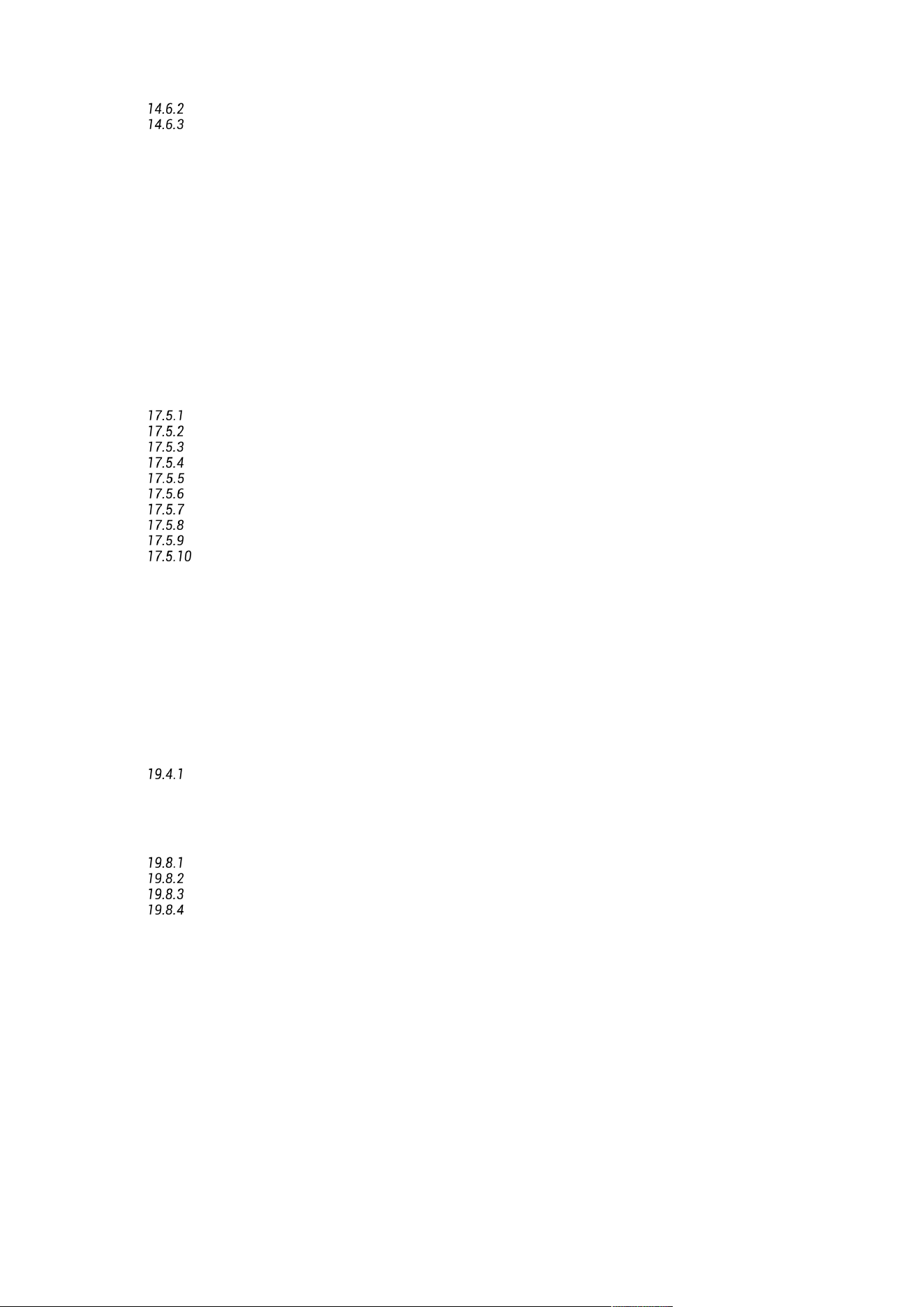
PHYSICAL CHARACTERISTICS
14
Chassis: 3.5U
Power supply: 240V AC / 50-60 Hz. Option: 130V
AC
Consumption: 90 W max.
Weight: ~14.5kg
Environmental conditions:
- Operating: 0°C-40°C (32°F-104°F)
- Humidity: 20%-80% relative humidity (without
condensation)
•
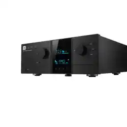
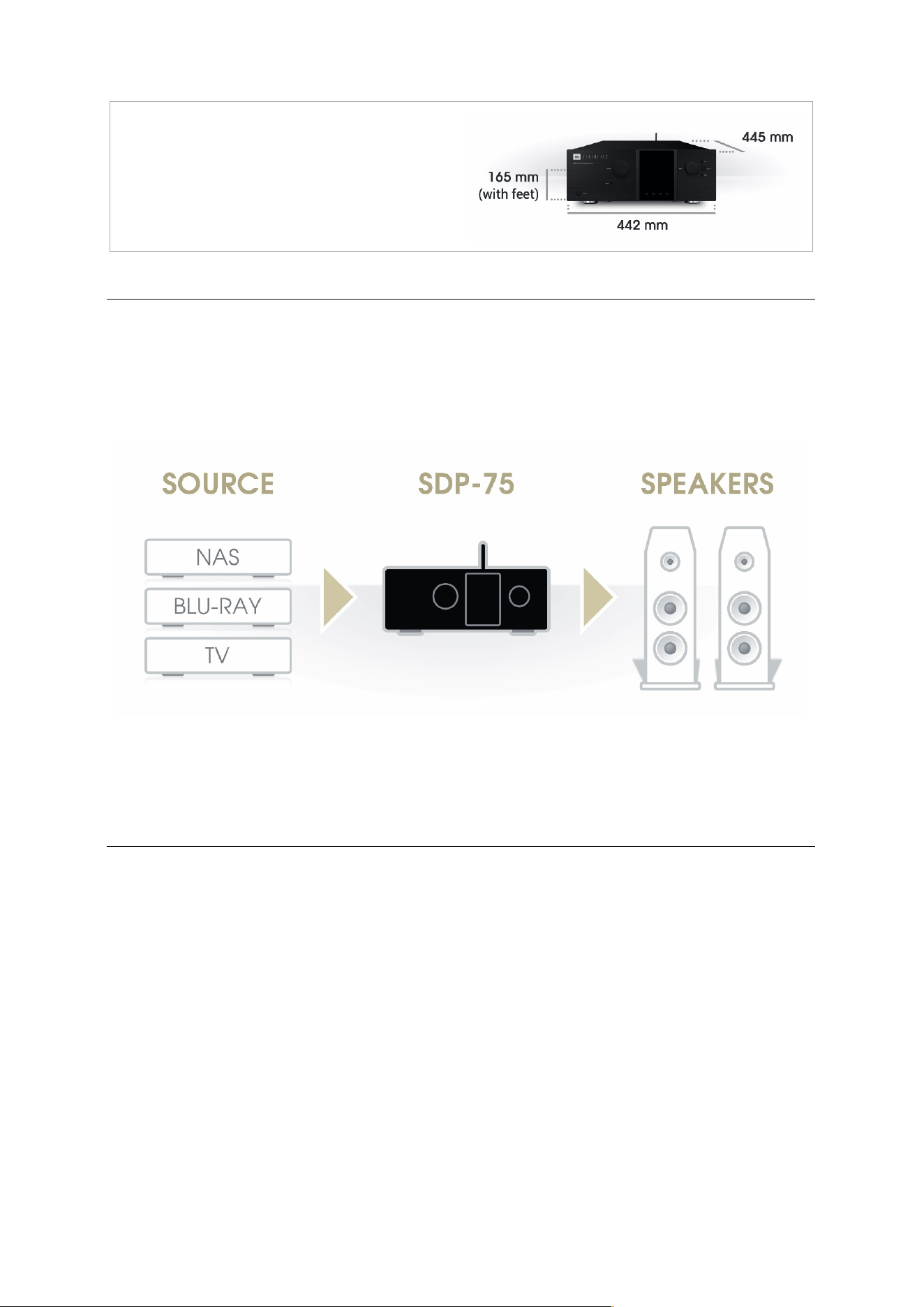
1.2 SYSTEM INTEGRATION
The SDP-75 is inserted before loudspeakers.
Figure#1:#SDP-75#system#integration#
1.3 JBL SYNTHESIS CERTIFIED INSTALLERS
The JBL SDP-75 surround processor provides an unprecedented degree of flexibility and automation, along with
decoding of every current format and very flexible speaker configuration. All of this results in a superior end-user
experience, with complex operations, such as automatically switching speaker configurations depending upon the
format being transparent to the end-user. The SDP-75 should only be installed and calibrated by a certified JBL
Synthesis Installer.
15
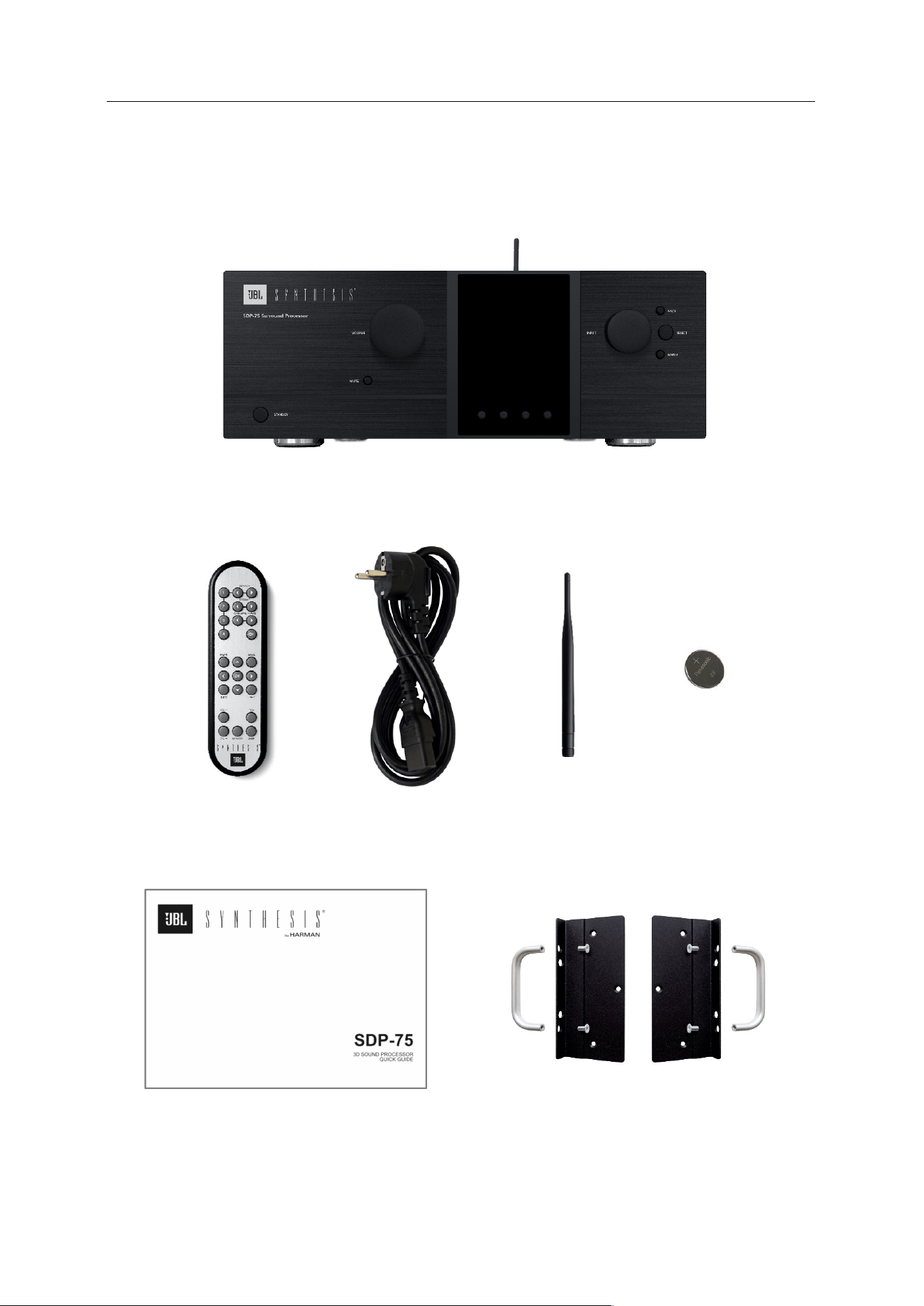
1.4 UNPACKING THE SDP-75
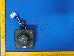
You will find in the SDP-75 packaging:
The#SDP#Synthesis#SDP-75
#
Surround#Processor#
Remote#Control#
Power#Cord#
Wi-Fi#Antenna#
CR032#Battery#
SDP-75#Quick#Guide#
Rack#Ears#
#
16
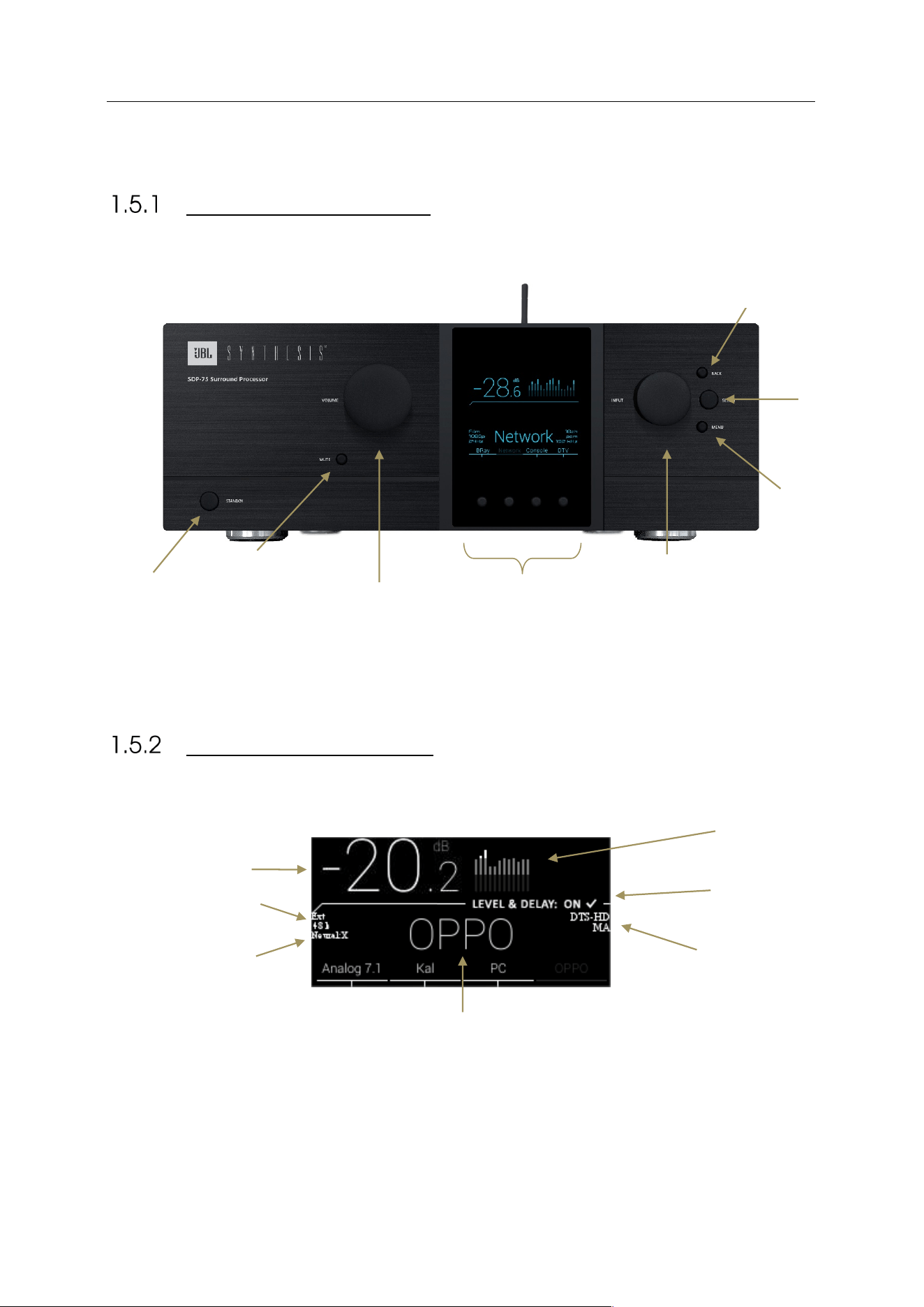
1.5 THE HARDWARE
FRONT PANEL LAYOUT
FRONT PANEL DISPLAY
Select
Button
Source/Item
Selection Knob
Volume
Knob
Mute
Button
Power
Switch
Back
Button
Menu
Button
Alignment
Status
Output
Meters
Audio Sync
Status
Output Level
Current
Source
Audio Format
Direct Source
Selection
Current Up-
mixer
17
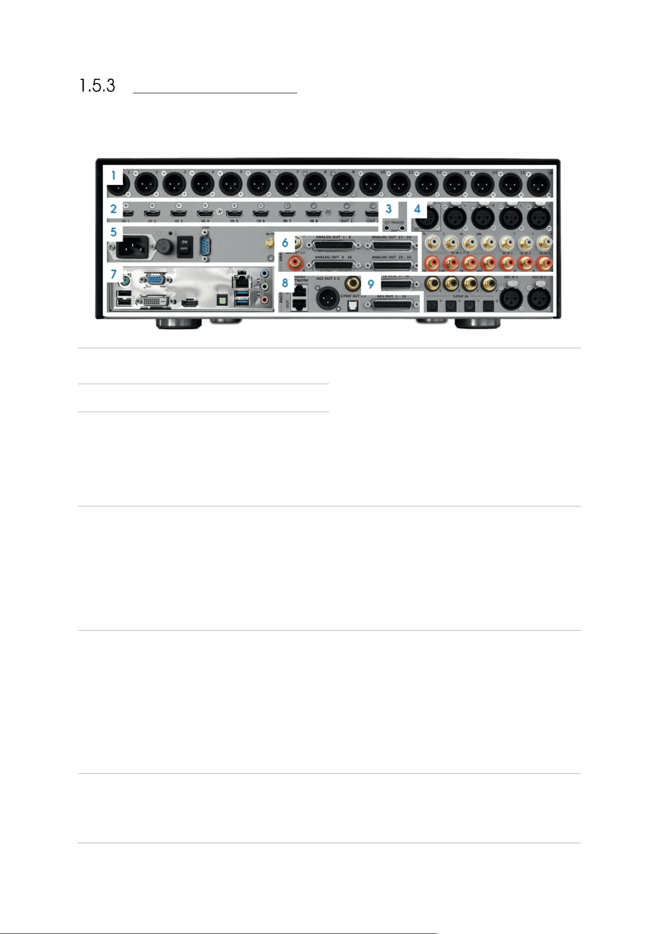
REAR PANEL LAYOUT
1
ANALOG OUTPUTS 1-16 ON XLR
CONNECTORS
7
PC CONNECTORS may change following PC
motherboard updates
• Video output (VGA/DVI/HDMI)
• 2x USB 2.0 + 2x USB 3.0
• Parallel port (unused)
• PS/2 Keyboard/Mouse
• RJ45 Gigabit Ethernet
• Audio ports (unused)
2
HDMI 1.4A 8 INPUTS, 2 OUTPUTS
3
TRIGGER 12V IN/OUT
4
ANALOG INPUTS
• 1x Microphone Input (unused)
• 2x Stereo Inputs on XLR
• 1x 7.1 Input on RCA
• 3x Stereo Inputs on RCA
8
DIGITAL OUTPUTS
• 1x AES3 (8 or 16 channels) on DB25
• 1x Stereo AES/EBU on XLR
• 1x Stereo S/PDIF on RCA
• 1x Stereo S/PDIF on Toslink
• 1x AML Extension link on RJ45
5
POWER
• AC Input
• Fuse
• Power Switch
• RS232
• Serial Number
• Wi-Fi Antenna Connector
9
DIGITAL INPUTS
• 1x AES3 DCI compliant (8 or 16 channels) on
DB25
• 4x SPDIF on RCA / 1x 7.1 PCM
• 4x SPDIF on Toslink / 1x 7.1 PCM
• 2x Stereo AES/EBU on XLR
6
ANALOG OUTPUTS
• 1-32 on 4x DB25 Connectors
• 1x Stereo on RCA
18
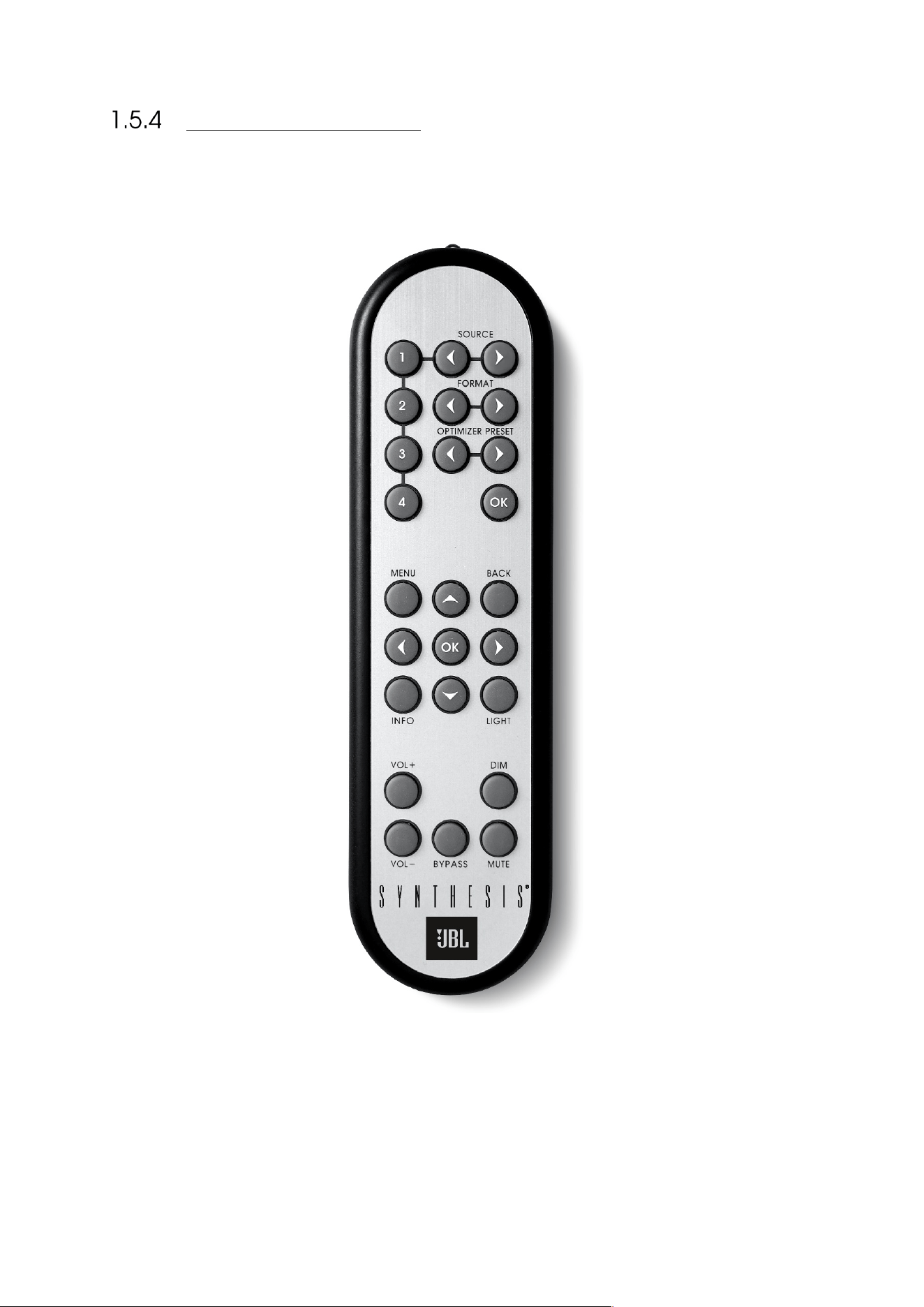
IR REMOTE CONTROL
1 TO 4
Direct source selection
SOURCE
Source selection
FORMAT
Listening Format playback mode
selection
PRESETS
Preset selection
MENU / BACK / ARROWS
Navigation in the front panel menu
LIGHT
Switches off the backlight on the
front panel
VOL +/-
Volume control (1dB step)
DIM
Decreases the volume by 20dB
(toggle button)
MUTE
Mutes audio outputs (toggle button)
BYPASS
Optimizer bypass
19
1.6 THE SOFTWARE
AVAILABLE OPTIONS TO ACCESS THE GRAPHICAL USER
INTERFACE
The SDP-75 offers multiple options to display and control the user interface:
• Directly with a physical display, a mouse and a keyboard connected to the PC connectors of the SDP-75.
• Remotely with a VNC Client over the network, from any computer or tablet to access the full user interface
in order to operate and/or setup the SDP-75.
• Remotely with an internet browser, with a limited access to the user interface allowing to operate the SDP-
75 but without all the setup menus.
The Graphical User Interface of the SDP-75 is specifically designed for touch screen use but it is just
as easy to use with your laptop’s trackpad or with a mouse.
Figure#2:#graphical#u se r#in te rfa c e #o f#th e #SDP-75#
NOTE: The design and the user experience of the SDP-75’s Graphic User Interface are constantly
improved with software updates.
20
IMPORTANT NOTE ABOUT THE WEB-BASED INTERFACE
The SDP-75‘s full user interface can only be accessed by connecting a display or through a VNC client.
If you’ve already completed the setup of the SDP-75 in your home theatre system and you only need to operate it, a
limited part of the SDP-75‘s user interface is also available from a web browser.
NOTE: The web browser can only display the HTML-based pages of the user interface. However, most
of the system setup pages of the SDP-75
are currently Linux-based. Therefore, the web browser can
only be used for daily operations of the SDP-75 but cannot be used to setup, measure and align the
level and delay of your speaker system.
To connect to the web user interface of the SDP-75‘s you need to enter its IP address in your web browser.
The IP address of the SDP-75 can be retrieved:
• via the front panel: go to the Setup/Network/Ethernet menu.
• by connecting a monitor and a mouse to the back panel. Go to the Network page of the graphical user interface.
If you are already connected to the SDP-75 with a VNC Client, you can easily check its IP address:
• Using Mocha VNC: click on the blue arrow, located at the right of the VNC Server address field;
• Using Chicken VNC: select the SDP-75 from the server list.
Please refer to the Network Setup chapter for further details about network configuration.
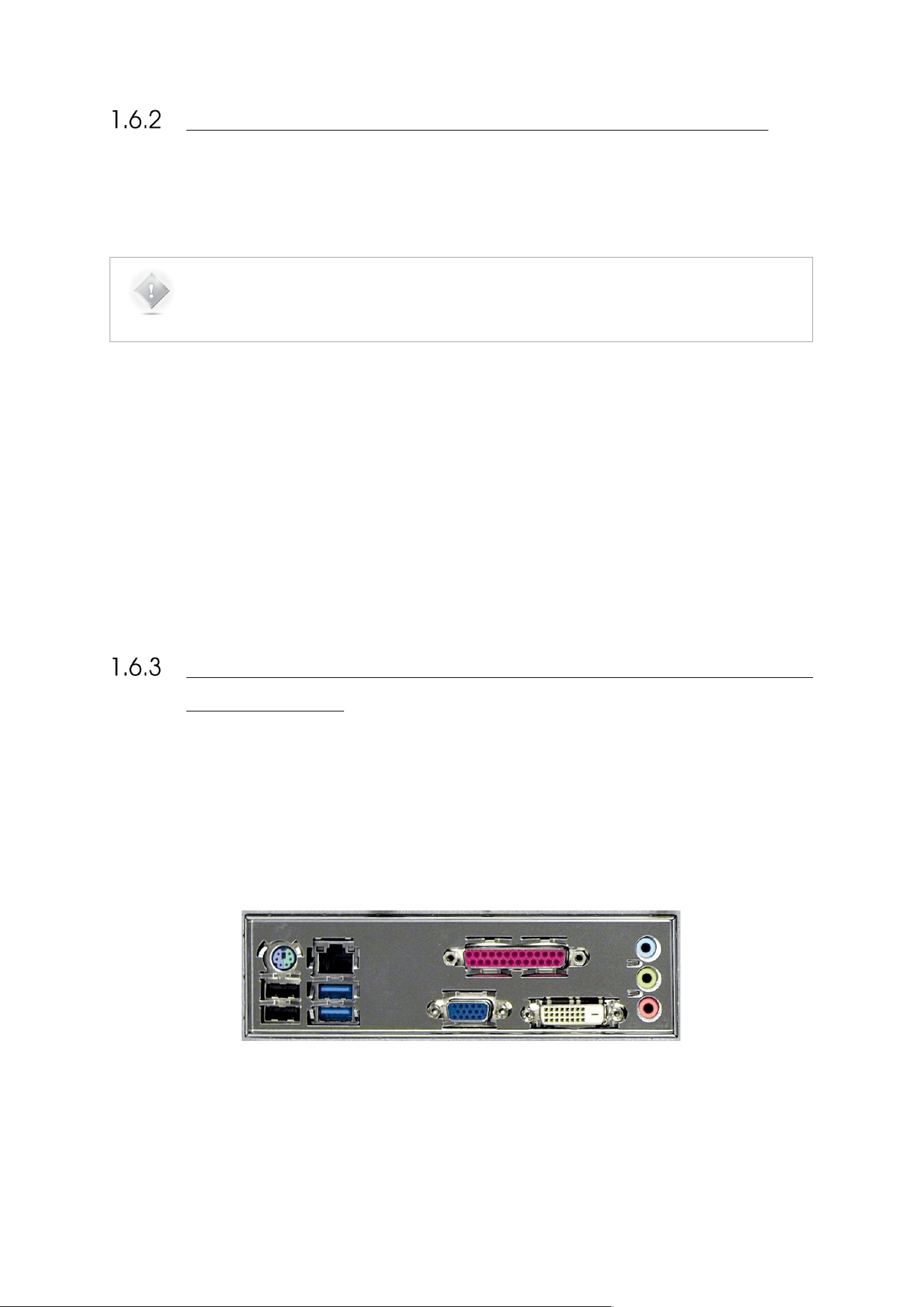
USING A DISPLAY, MOUSE AND KEYBOARD CONNECTED
TO THE SDP-75
A very straightforward option to access and control the user interface of the SDP-75, provided that you have the
necessary equipment, is to connect a physical display and use a mouse and a keyboard to control the SDP-75 software.
These devices shall be connected to the PC’s connectors, located on the rear panel of the SDP-75:
• PC/Mouse can be connected either using the PS/2 or USB ports.
• Physical monitor can be connected through the VGA, DVI-D or HDMI ports. The PC video outputs may change
following the mother board reference.
Figure#3:#SDP-75#PC#connector’s#panel#
21
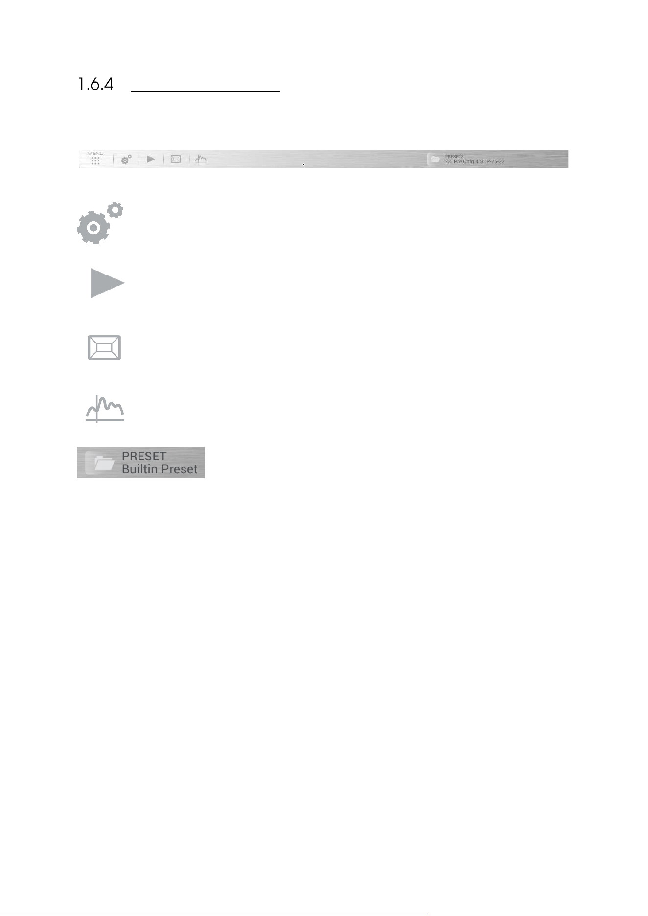
THE TOP MENU BAR
The Top Menu provides access to the main features of the SDP-75.
Opens the Advanced settings graphical user interface, used for configuring your sources, level and delay
alignment, advanced processor settings, network setup, etc. Most of its functionality is explained in the
chapters Calibrate the Speakers in the Room and Tuning the Optimization Settings.
Opens the lateral Play menu used for daily operation: level adjustment, source selection and general
information. See the chapter Daily Operations.
Opens the Speakers/Room setup tool, used for setting up your speaker system and for routing the
channels to the speakers. See the chapter Specify the Speaker Layout.
Opens the Fine Tuning page, which includes the Bass Management and the Advanced Settings. See the
chapters Setup Bass Management and Tuning the Optimization Settings.
is a drop-down menu useful for quickly selecting a preset.
22
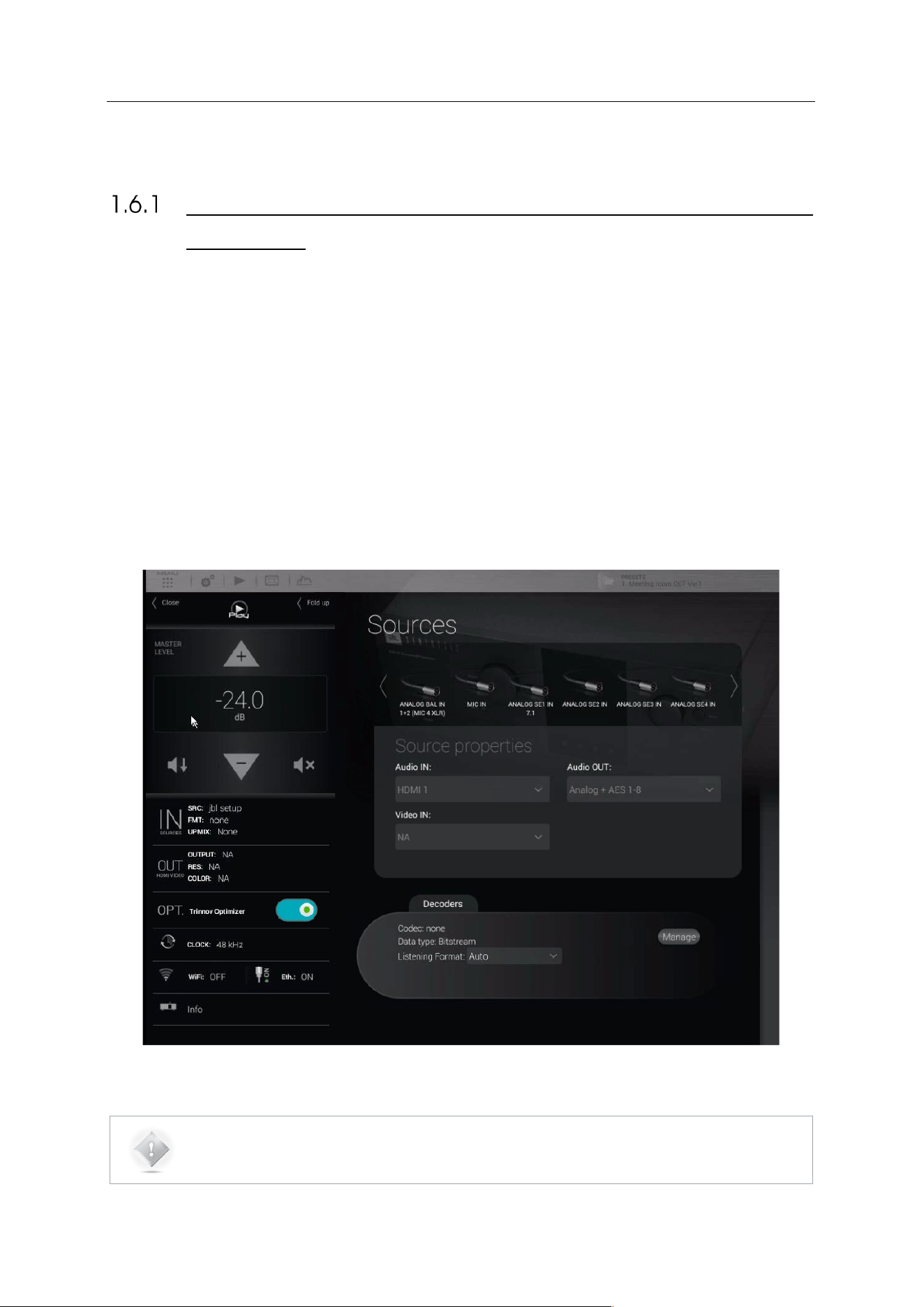
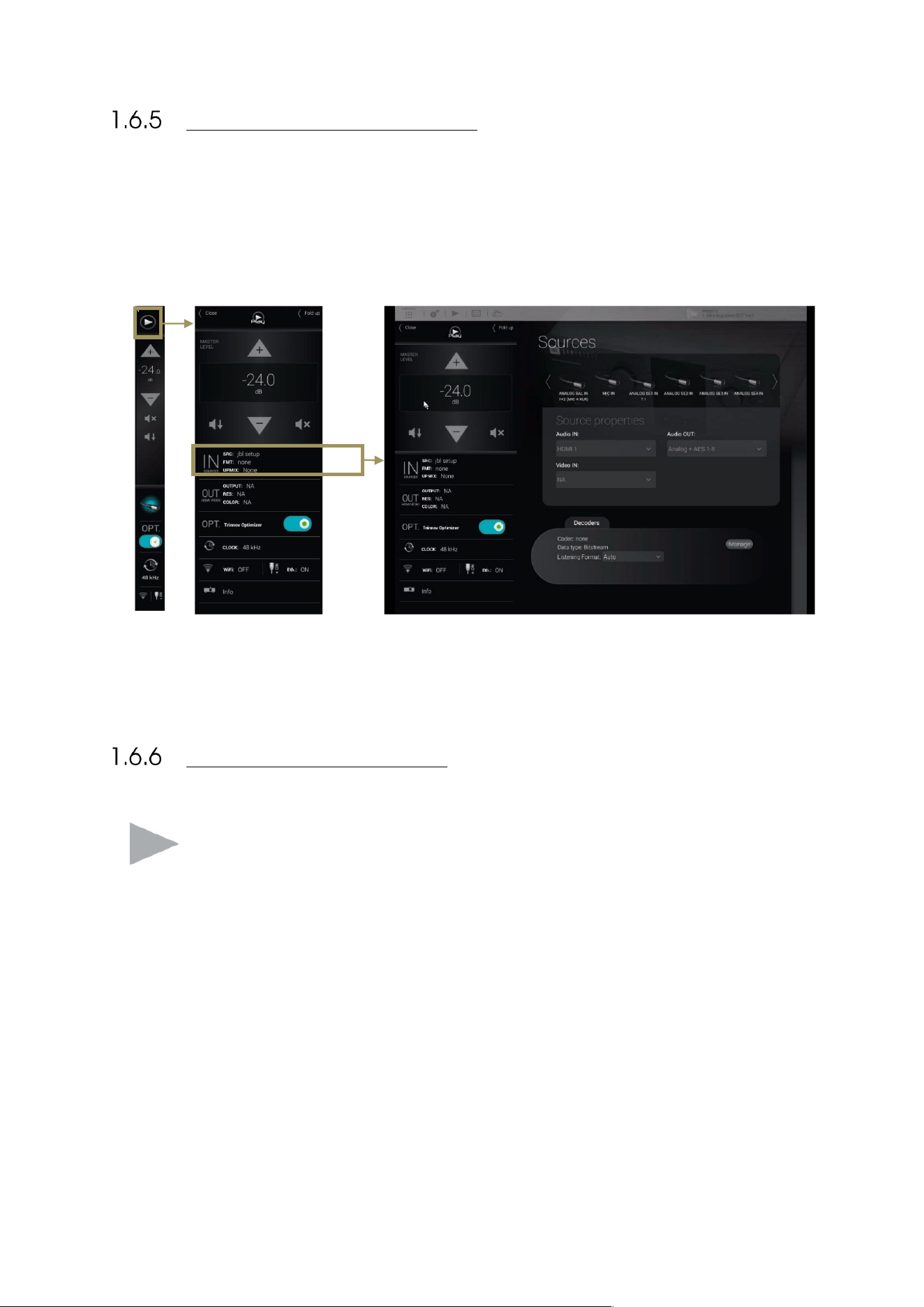
THE MAIN USER INTERFACE
The main page of the SDP-75
is used for daily operation:
1. Click on the Play button on the top left corner of the interface: the lateral menu unfolds,
2. Select one of the tabs to open the corresponding panel. For example, the Input Sources tab opens the Sources
panel,
3. Perform a daily operation, such as selecting a different source.
A detailed description of this interface is provided in the following pages.
THE LATERAL MENU BAR
You can access the Play menu, located on the left-hand side of the user interface, at any time by clicking
on the “Play” button on the Top menu.
This menu constantly provides information about the current status of the SDP-75. It can be folded or
unfolded depending on the task you wish to perform.
23
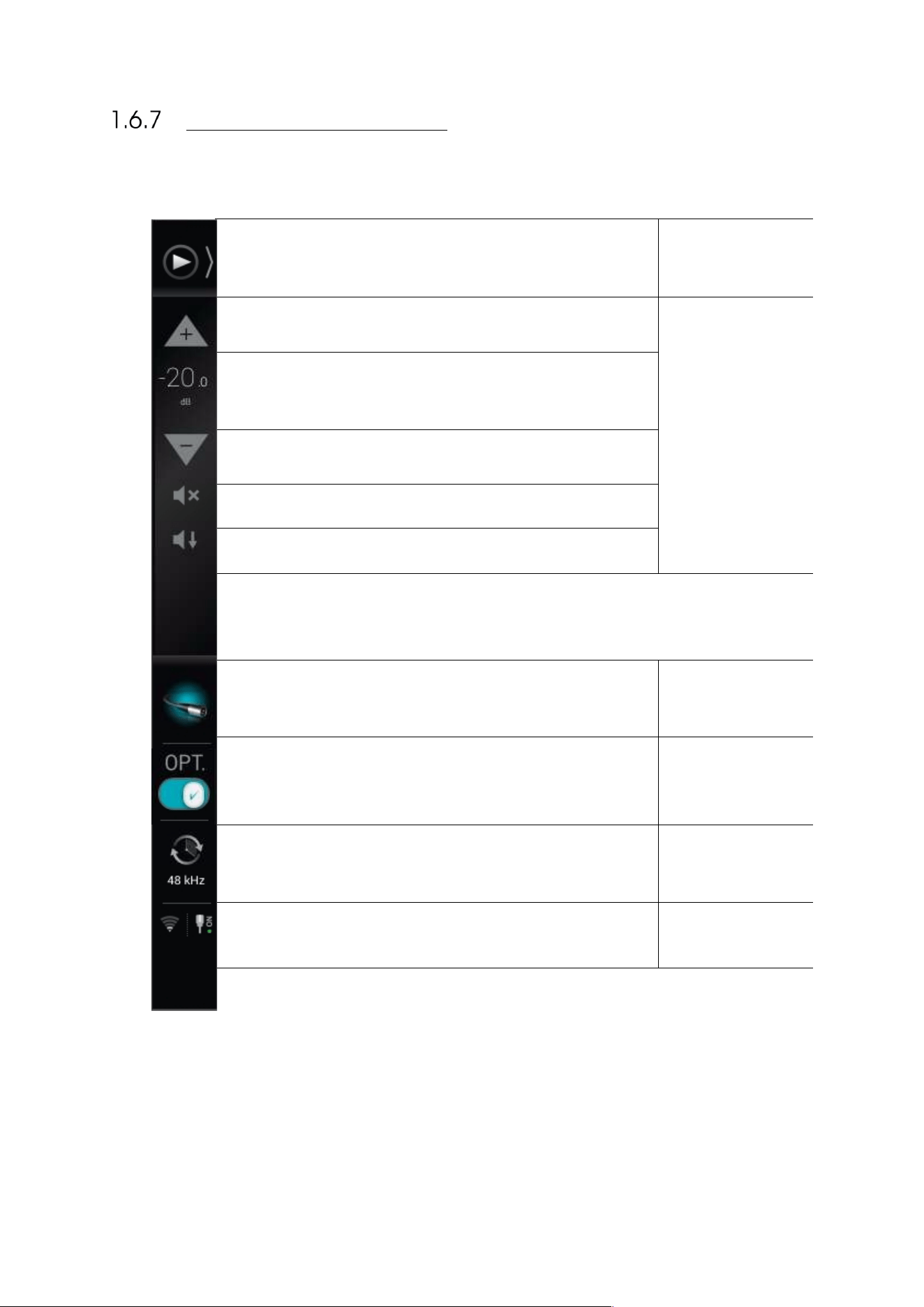
FOLDED LATERAL MENU
When folded, the lateral menu provides the following features:
Click to unfold the lateral menu.
Unfold button
Click to increase output level added in 1dB steps.
Volume Control
Displays the current output level.
Click to decrease output level added in 1dB steps.
Mute: cuts all outputs.
Dim: attenuates the output level by 20dB.
Displays which audio source is currently selected as you move the
cursor over the icon.
Source Information
Displays the current status of the Optimizer.
Click to enable/disable the Optimizer.
Optimizer Status
Displays the current clock sampling rate.
Audio Clock
Displays the current status of the Wi-Fi and Ethernet network
interfaces of the SDP-75.
Network Status
24
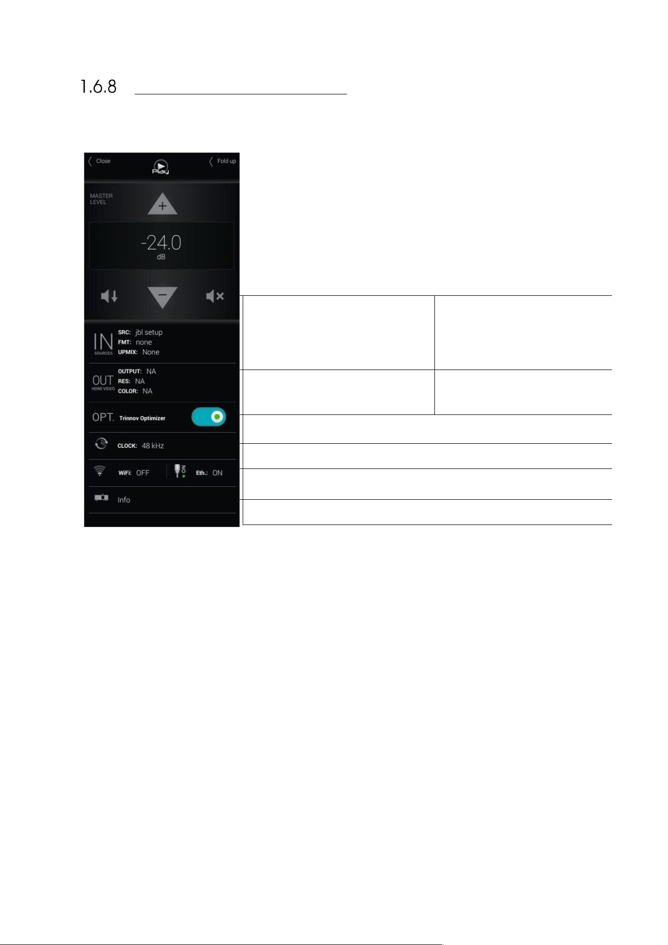
UNFOLDED LATERAL MENU
When unfolded, the lateral menu displays extra information about the current settings
of the SDP-75:
•
IN sources
• SRC: the name of the current audio
source
• FMT: the audio format
• UP-MIX: The up-mix format
OUT channels
• EQ: the current user EQ
• OUT: the current audio output
OPT displays the current status of the Optimizer.
CLOCK displays the current sampling rate.
Wi-Fi and Ethernet network status
More information on your SDP-75
25
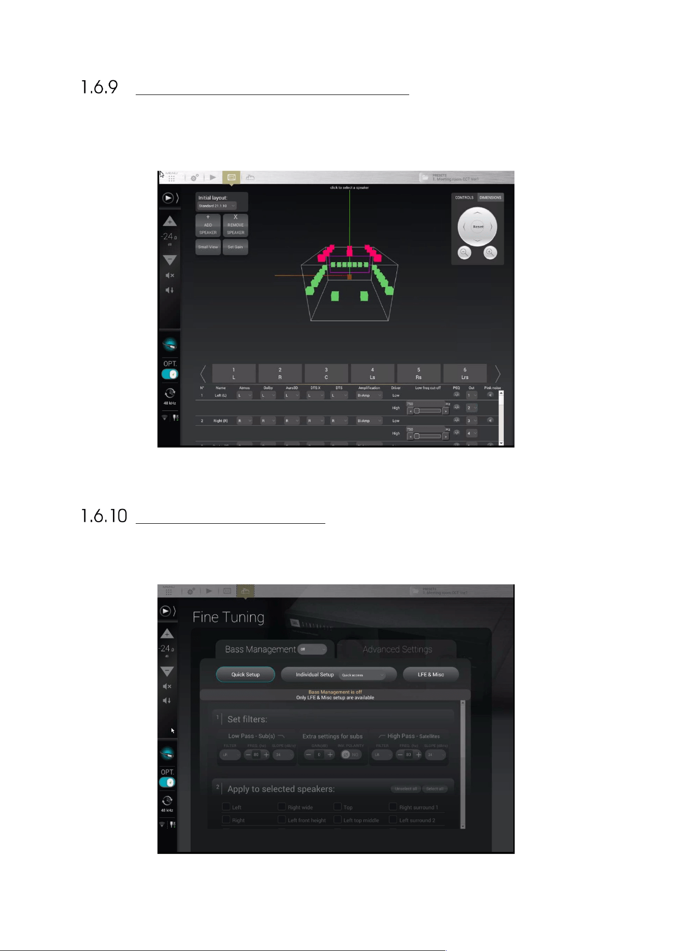
THE SPEAKERS/ROOM SETUP TOOL
The speakers/room setup tool is a highly practical tool used to setup your system. It is explained in
the Specify the Speaker Configuration chapter.
Figure#4:#The#Speakers/Room#setup#tool#
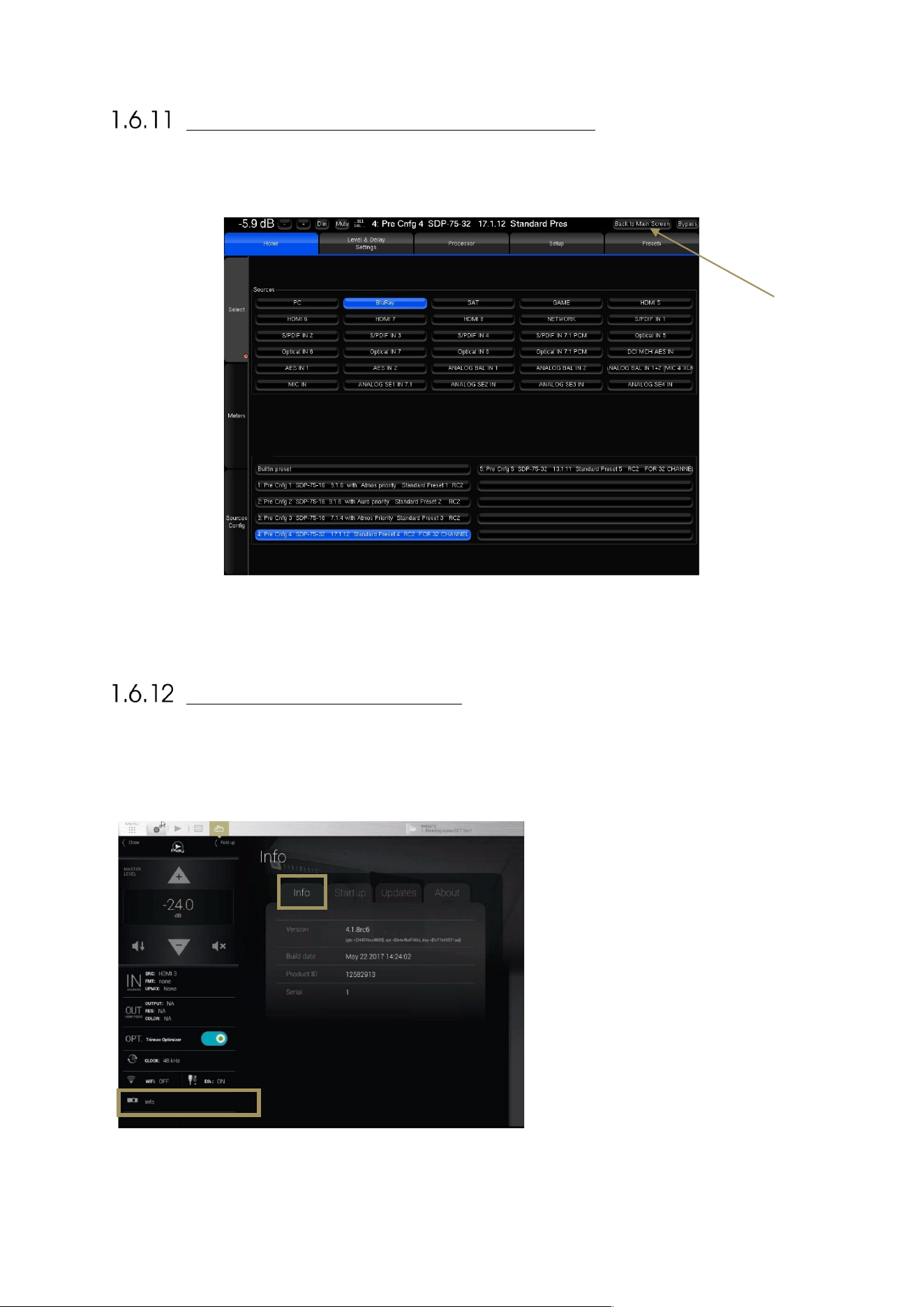
THE FINE TUNING PANEL
The Fine Tuning panel gives access to Bass Management and Optimizer settings:
26
THE ADVANCED SETTINGS INTERFACE
The advanced settings of the SDP-75
are currently available through a specific user interface:
Figure#5:#The#advanced#settings#user#interface#of#the#SDP-75
#
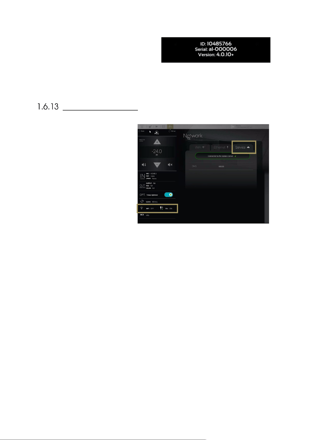
PRODUCT INFORMATION
Product Information can be displayed on the Graphical User Interface default startup page and/or on
the front-panel menu of the SDP-75.
Figure#6:#Product#informa tion #pag e #
• Version: software version currently
installed
• Build date: software release build date
• Product ID: SDP-75 unique ID number
of the unit
• Serial: serial number of the unit
#
Use this button
to go back to the
Main screen
27
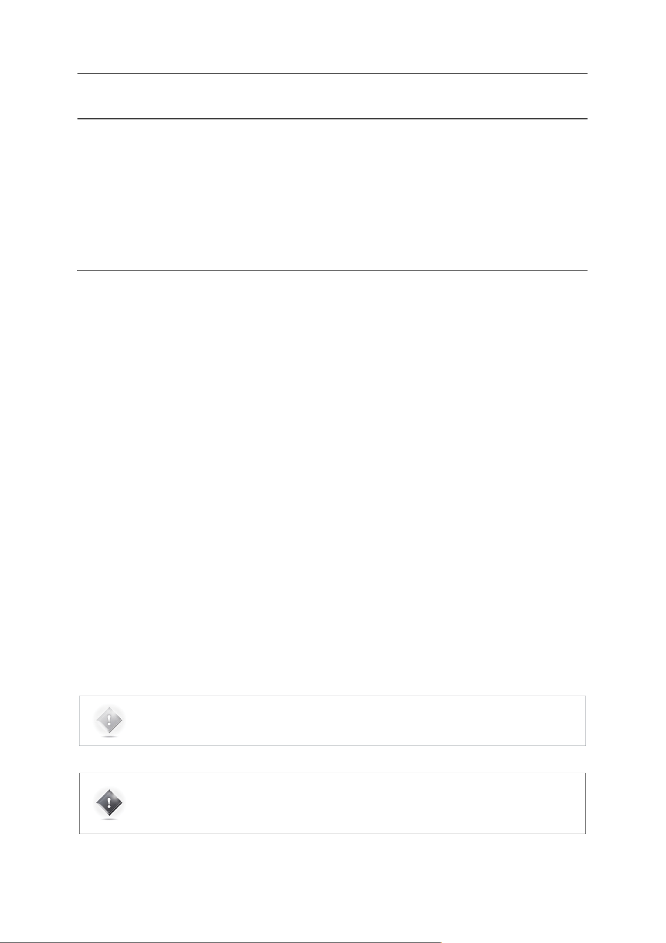
To display the About page on the front panel, hit the
Menu button on the front panel of the SDP-75, select
the last item About and hit the Select button.
#
•
#
Figure#7:#The#front-panel#About#page#
SOFTWARE UPDATES
The SDP-75
was designed to maintain its
leadership over time and will therefore benefit
from continuous updates as well as new
features.
Software updates and support can be
performed remotely by JBL Synthesis
provided that the Processor is connected to
the internet and that outgoing connections to
port 22 is open.
Figure#8:#The#Network/Service#page#
#
28
2 NETWORK SETUP
This chapter explains how to connect with your preferred device (tablet, laptop or desktop computer)
to the SDP-75
through a Wi-Fi or Ethernet network.
2.1 CHOOSING A NETWORK CONFIGURATION
The SDP-75
offers multiple network options in order to meet two important requirements:
• using a wireless device (tablet or laptop computer) throughout the room while performing acoustical
measurements with the SDP-75’s level and delay alignment tools;
• seamlessly integrating the SDP-75
into your home theatre’s technical environment;
Depending on the specific technical environment of your home theater, each of these requirements may or may not
correspond to the same network configuration.
We recommend the following strategy for the network setup of your SDP-75:
1. Setup Procedure: choose a network configuration that meets your requirements for the setup process. Three
options are possible:
A. The SDP-75 joins your local Wi-Fi network as a Wi-Fi client;
B. The SDP-75 joins your local Ethernet network as an Ethernet client;
C. Your device connects to the SDP-75’s own Wi-Fi network (Access Point).
2. Final installation: if needed, change the network configuration to meet the requirements to integrate the SDP-
75 into your overall home theater system. For the final installation of the system, we suggest to leave your
SDP-75 permanently connected to the local network. Two options are possible:
A. Connect an Ethernet cable between the SDP-75’s back panel and your ISP box. With this option, the
SDP-75 will always be available through your local network. This is the easiest option because the
SDP-75’s default DHCP network settings allows it to connect automatically to a local Ethernet
network.
B. Setup the SDP-75 network settings to connect as a Wi-Fi client to your ISP Box’s Wi-Fi access point.
This process is explained in the Advanced Wi-Fi Settings subchapter at the end of this chapter.
NOTE: You could also choose to leave the SDP-75 disconnected from your local network but this will
probably be less convenient if you want to access the Internet from the same device that is used to
operate the SDP-75.
IMPORTANT NOTE: Whatever option you choose for connecting to the SDP-75 through a network,
please keep in mind that the SDP-75 and your control device (tablet or computer) must be connected
to the same network, or to interconnected networks, such as a Wi-Fi network interconnected to an
Ethernet network.
29
2.2 CONNECTING TO THE SDP-75
OVERVIEW OF THE NETWORK CONNECTION PROCEDURE
The factory settings of the SDP-75
are designed to make it as easy as possible to establish the first
network connection between your device (tablet or computer) and the SDP-75
so that you can
access its graphic user interface.
IMPORTANT NOTE: Please keep in mind that another straightforward option for using the SDP-75 is to
connect a display, mouse, and keyboard directly to the back panel PC connectors.
The following overview introduces the main steps of the network connection procedure in order to help you understand
the overall process and choose your preferred options:
1. Step 1: download and install a VNC Client software application on your device.
2. Step 2: put the SDP-75
and your device on the same network. Choose one of these options:
A. Your device joins the SDP-75’s Wi-Fi network: Disconnect your device from your usual Wi-Fi network
and connect it to the SDP-75‘s own Wi-Fi network (Access Point).
B. The SDP-75 joins your existing Wi-Fi network: use the SDP-75’s front panel menus to connect it to
your local Wi-Fi network.
C. The SDP-75
joins your existing Ethernet network: use an Ethernet cable to connect the SDP-75
to your
local Ethernet network.
3. Step 3: open your VNC Client and configure it to connect to the SDP-75’s VNC Server. Choose one of these
options:
A. iOS devices, Android devices or Mac OS X computers: the zeroconf-enabled VNC clients available for
these devices will not require knowing the IP address of the SDP-75.
B. Windows computers: you will need to configure your VNC client (Tight VNC) with the IP address of
the SDP-75.
4. Once your VNC Client is configured correctly, connect to the SDP-75’s VNC Server and start using the SDP-
75’s graphical user interface.
These steps are described in detail in the following pages.
30
STEP 1: DOWNLOAD AND INSTALL A VNC CLIENT ON
YOUR DEVICE
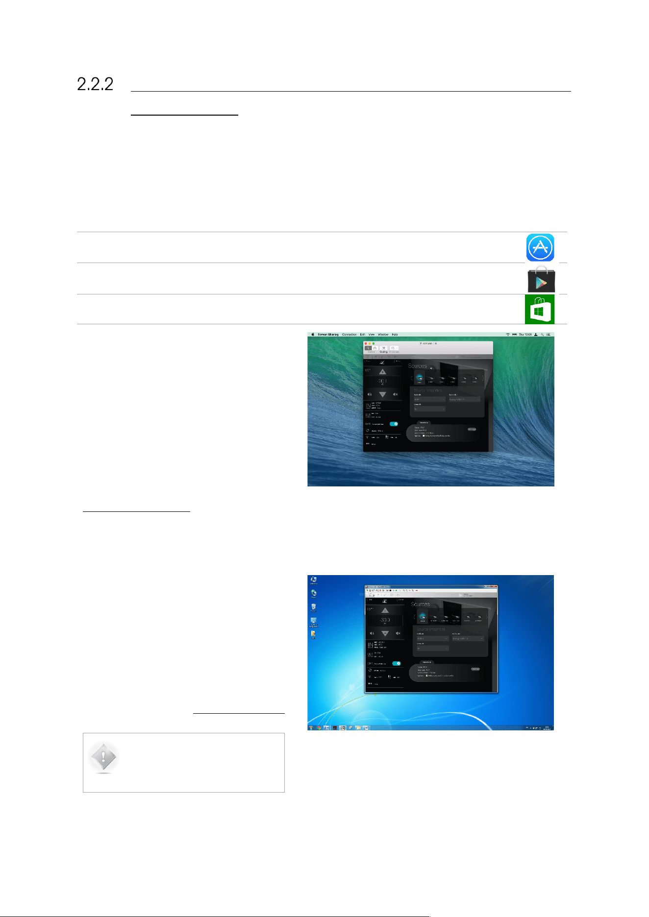
2.2.2.1 USING A TABLET
If you are connecting from an iOS, Android or Windows tablet you need to download and install a VNC
Client app on your tablet. A number of VNC Clients/Viewers are currently available. We recommend
the Mocha VNC Lite free app:
iOS devices (Apple iPad): use the App Store app to download and install the Mocha VNC Lite app from
Apple’s App Store.
Android devices: use the Play Store app to download and install the Mocha VNC Lite app from Google’s
Play Store.
Windows mobile devices: use the Windows Store app to download and install the Mocha VNC Lite app
from the Windows Store.
2.2.2.2 USING A MAC OS
X COMPUTER
If you are connecting from a Mac OS X computer
running OS X version 10.5 or higher, you can
choose to use Apple’s Screen Sharing VNC client
integrated into the OS X operating system. In this
case you don’t need to download an additional
app and you can skip to the next step.
If your Mac is running OS X version 10.4 or lower,
you need to install a VNC client software:
download and install Chicken of the VNC from
www.macupdate.com
Figure#9:#the#SDP-75’s#graphical#user#interface##
from#a#Mac#O S#X #desk top #
2.2.2.3 USING A
WINDOWS
COMPUTER
If you are connecting from a Windows computer,
you need to download and install a VNC Client
software. A number of VNC Clients/Viewers are
currently available.
We recommend Tight VNC: download and install
Tight VNC from www.tightvnc.com
NOTE: Tight VNC is not zeroconf-
enabled. You will need to enter
the IP address of the SDP-75 in
order to connect.
Figure#10:#the#SDP-75’s#graphical#user#interface#from#a#
Windows#desktop#
31
STEP 2: PUT THE SDP-75 AND YOUR DEVICE ON THE SAME
NETWORK
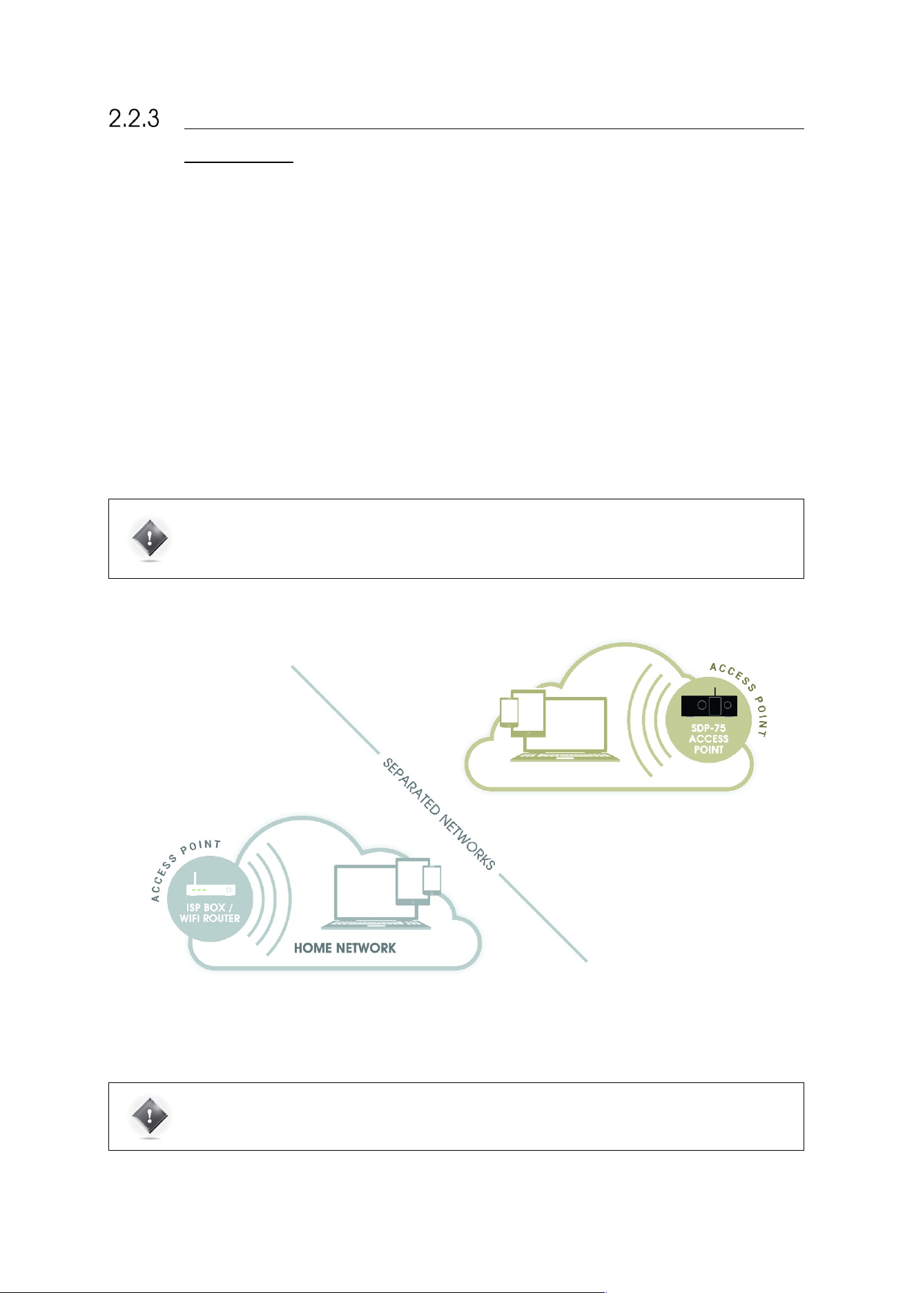
2.2.3.1 OPTION A: YOUR DEVICE JOINS THE SDP-75’S WI-FI
NETWORK
The factory settings of the SDP-75
are preconfigured to allow it to run as a Wi-Fi Access Point. Provided that the Wi-Fi
antenna is connected to its back panel, the SD¨-75
will run its own Wi-Fi Access Point. The SDP-75
access point should
appear in the list of Wi-Fi networks under the name “SDP-XX”, where XX is the serial number of your SDP-75.
The fully wireless option for connecting to the SDP-75
is as follows:
• Disconnect your device (computer or tablet) from your usual Wi-Fi network;
• Connect your device to the SDP-75’s own Wi-Fi network: in your list of Wi-Fi networks, choose the network
named “SDP-XX”, where “XX” is the serial number of your SDP-75. Enter the following password: calibration
• Use the SDP-75 front panel to check its network status: go to the Setup/Network menu to see its IP address.
Once your computer or tablet is on the SDP-75’s own Wi-Fi network, you can move to the Next Step of this procedure to
configure and connect your VNC client to the SDP-75’s VNC server.
IMPORTANT NOTE: The SDP-75 Access Point’s password is calibration
The SDP-75’s Access Point details are available through the front panel menu in the Setup > Network
> Wi-Fi page.
Figure#11:#joining#the#SDP-75’s#network#(Access#Point)#
IMPORTANT NOTE: Once connected to the SDP-75’s Access Point, it is possible to remotely access the
SDP-75’s graphic user interface, but access to Internet will be lost, as indicated in the figure above.
You must switch back to your usual Wi-Fi network in order to reconnect to the internet.
32
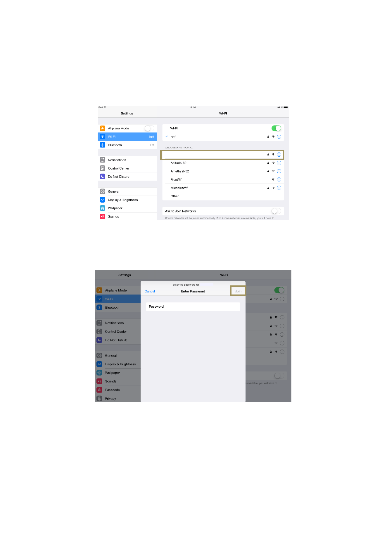
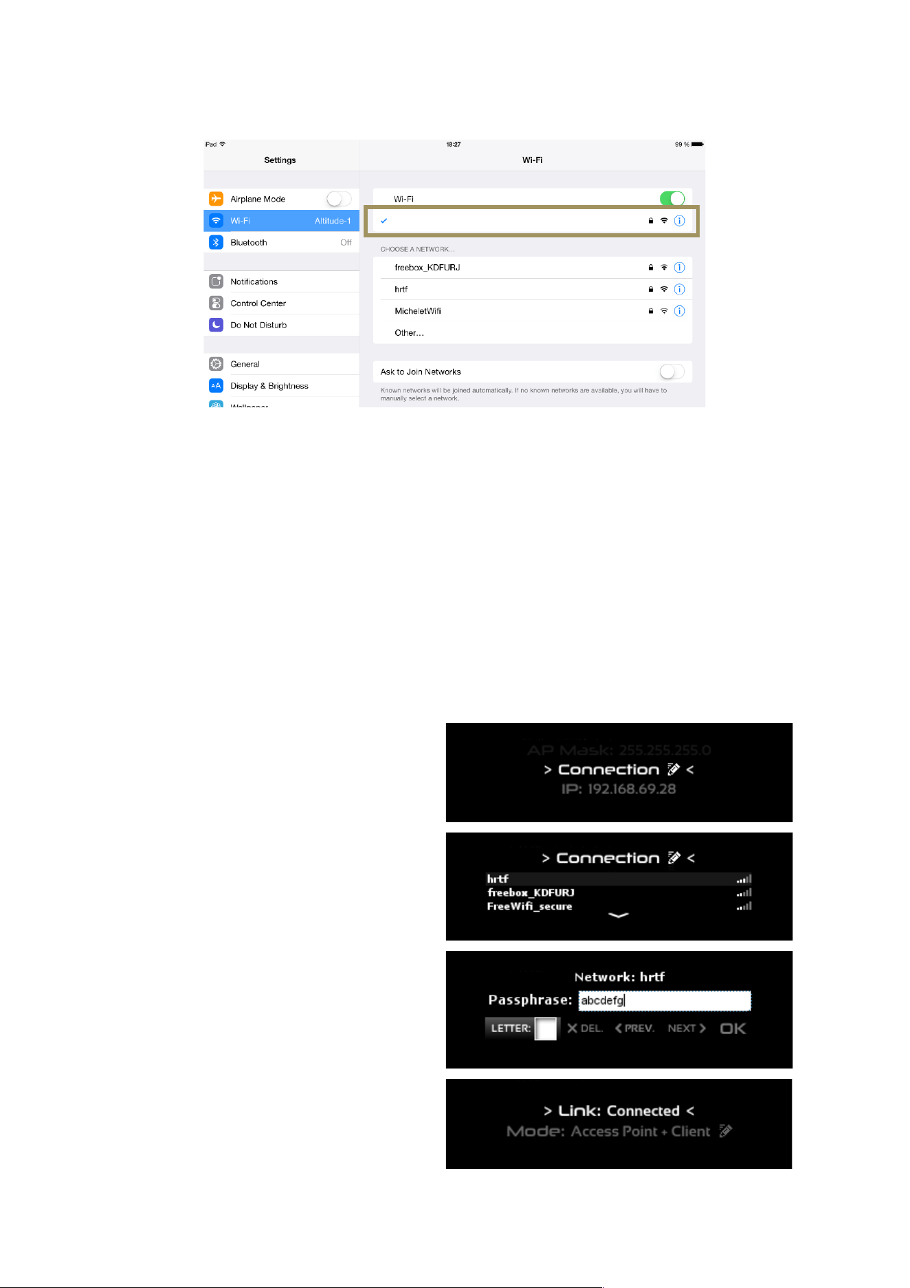
CONNECTING WITH YOUR IPAD
The following screenshots, created on an iPad, are provided as an example of how to connect to the SDP-75 Access
Point. The process is extremely similar on a Mac OS X, Android, or Windows device, you simply need to find the Wi-Fi
Settings page.
• Go to Settings and click on the Wi-Fi menu item located in the top left side of the page.
• In the “Chose a network…” list, click on the network SDP-XX, where XX is the serial number of your SDP-75.
Figure#12:#choosing#a#Wi-Fi#network#in#the#iPad#settings#
#
• When asked to Enter the password for “SDP-XX”, type the following password: calibration
• Click on the Join button.
•
Figure#13:#entering#the#pa s sw ord#to#join#th e #SDP-75’s#Wi-Fi#network#
#
JBL_SRP-75-6
JBL_SRP-75-6
33
• You should now see the SDP-XX network as the currently connected Wi-Fi network on top of the page and on
the top left side of the page:
Figure#14:#the#iPad#is#now#connecte d #to#the#SDP-XX#Wi-Fi#network#
Once you are connected, you can move to the next step of the procedure: configure and connect your VNC client to the
SDP-75’s VNC server.
2.2.3.2 OPTION B: THE SDP-75 JOINS YOUR EXISTING WI-FI
NETWORK
The most flexible network option for the final installation of your SDP-75 is to connect it as a Wi-Fi client to your existing
Wi-Fi network. This will allow you to connect to the SDP-75
and to the Internet simultaneously, without switching back
and forth between two different Wi-Fi networks.
To connect the SDP-75 to an existing Wi-Fi network
you need to use the front panel menus to change the
Wi-Fi settings:
1. Click on the menu button on the front
panel.
2. Select the Setup > Network > Wi-Fi page.
3. Turn the Source/Item selection knob to
scroll through the settings until you see
the Connection item:
4. Push the Select button. This will display
the list of available Wi-Fi networks:
5. Scroll to the name of the Wi-Fi network
you want to join, and press the Select
button. If you select an encrypted
Access Point, you will be asked for the
passphrase.
6. Enter the passphrase and press the OK
button:
7. You should now see that the Wi-Fi
status has changed to “Link:
Connected”:
This means that your SDP-75 is now connected to
the chosen Wi-Fi network.
JBL_SRP-75-6
34
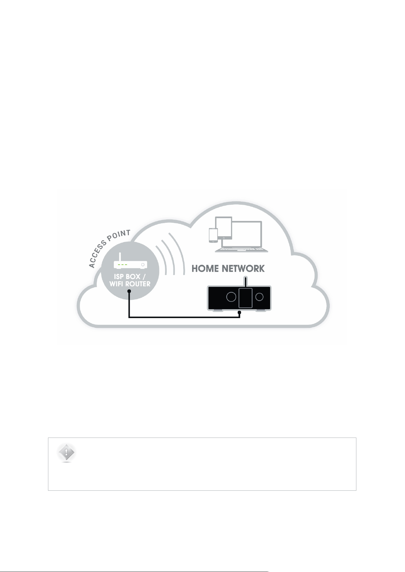
2.2.3.3 OPTION C: THE SDP-75 JOINS YOUR EXISTING ETHERNET
NETWORK
The factory setting for the SDP-75’s Ethernet mode is set to DHCP. Therefore, the SDP-75 will automatically be detected
and configured on most local networks.
The benefit of this Ethernet-based option is that you don’t need to switch your own device to another network. Therefore,
if your network has Internet access, you will remain connected to the Internet while also being connected to the SDP-75.
To connect the SDP-75 to your local Ethernet network:
• Use an Ethernet cable to connect the SDP-75 to your router or ISP Box;
• Use the SDP-75’s front panel to check that it now has an IP address: go to the Setup/Network menu to see
the network configuration.
Once the SDP-75 is connected to your local network, you can move to the next step of the procedure: configure and
connect your VNC client to the SDP-75’s VNC server.
Figure#15:#connecting#th e #SDP-75#to#an#ISP#box#
The figure above shows that the SDP-75 is hard-wired to the Internet Service Provider Box / Wi-Fi Router of the local
home network.
If your local network has a Wi-Fi Access Point, you can then access the SDP-75 from any wireless device connected to
your local Wi-Fi Access Point.
NOTES:
• This configuration only works if the router includes an active DHCP server.
• The standard settings of your ISP box should allow the SDP-75 to reach the Updates Server for
software updates through the internet.
35
STEP 3: CONNECT TO THE SDP-75 FROM YOUR DEVICE
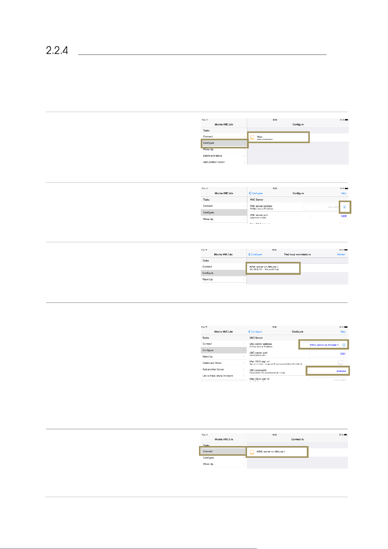
2.2.4.1 USING A TABLET WITH MOCHA VNC LITE
To connect to the SDP-75’s VNC Server from an iOS or an Android device, use the Mocha VNC Lite application:
• Open the Mocha VNC Lite app in your iOS or
Android device.
• Click on the Configure menu item located in the
top left of the page.
• In the Configure page, click on the line “New…
Add a configuration”.
#
Figure#16:#adding#a#new#VNC#Serv e r#configuration #
In the list of VNC Server parameters, click on the “i”
button located in the top right of the page, next to the
VNC server address.
Figure#17:#configuring#th e#V NC#Server#
In the list Find local workstations, select the line
named “#VNC Server on SDP-XX”, where XX is the
number of the SDP-75.
#
Figure#18:#selecting#the#VN C #S e rv er #SDP-XX#
The field VNC server address now shows the name
“#VNC Server on SDP-XX”, where XX is the number of
the SDP-75.
Go to the field VNC password and enter the password,
which is the six-digit serial number of the SDP-75:
● the password is 00000X, if the number of
the SDP-75’s VNC Server has a single
digit;
● the password is 0000XX if the number of
the SDP-75’s VNC Server has 2 digits;
● the password is 000XXX if the number of
the SDP-75’s VNC Server has 3 digits;
● etc…
The VNC Server is now configured.
Figure#19:#entering#the#pa s sw ord#
Now click on the Connect menu item. The “#VNC
Server on SDP-XX” should be listed in the page.
Select the line “#VNC Server on SDP-XX”.
The graphic user interface of the SDP-75 should now
be visible on the screen of your device.
Figure#20:#connecting#to #th e #SDP-75
'
s#VNC#server##
36
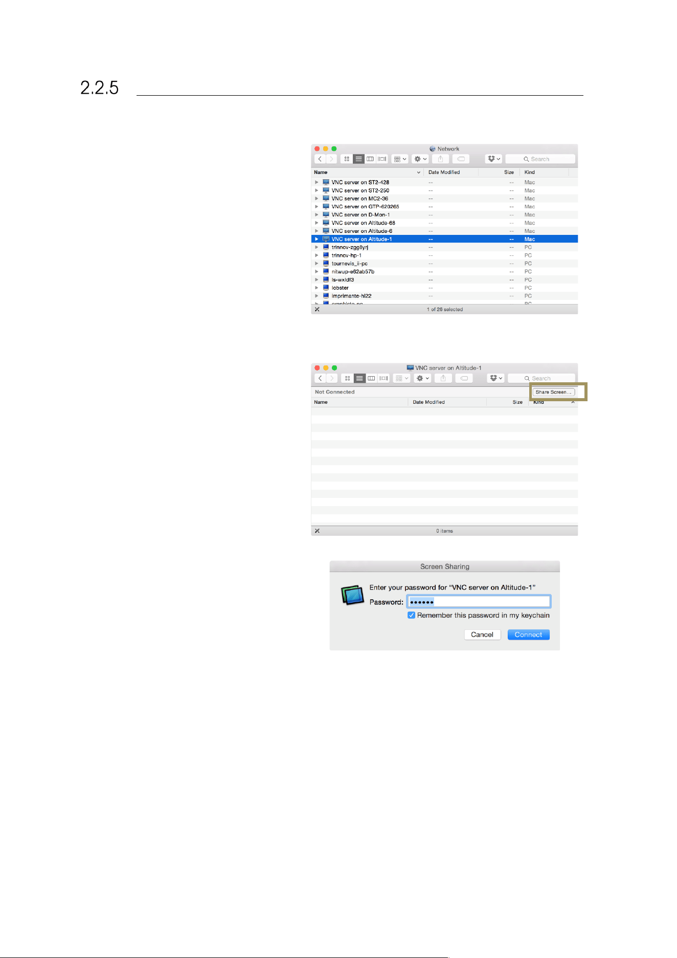
USING A MAC OS X COMPUTER WITH SCREEN SHARING
To connect to the SDP-75’s VNC Server from
your Mac OS X computer, you can use the
integrated Screen Sharing VNC client included
since OS X version 10.5 (Leopard):
1. Open the Finder application in your
Mac OS X computer.
2. Select the item Go > Network in the
Finder’s menu. This will display the
available VNC servers in your
network.
3. Select (double-click) the server “VNC
server on SDP-XX”, where XX is the
number of your SDP-75. This will
display the following window;
4. Click on the Share Screen… button.
This will display the Screen Sharing
login panel;
5. Enter the password, which is the six-
digit serial number of your SDP-75:
a. the password is 00000X, if the number
of your SDP-75’s VNC Server has a
single digit;
b. the password is 0000XX if the number
of your SDP-75’s VNC Server has 2
digits;
c. the password is 000XXX if the number
of your SDP-75’s VNC Server has 3
digits;
d. etc.
6. Click on the Connect button located
in the lower left corner of the window.
7. The graphic user interface of your
SDP-75 should now be visible on the
screen of your Mac.
Figure#21:#the#Network#p a g e#in#Mac#OS #X 's#F in d e r#
37
USING A MAC OS X COMPUTER WITH CHICKEN OF THE
VNC
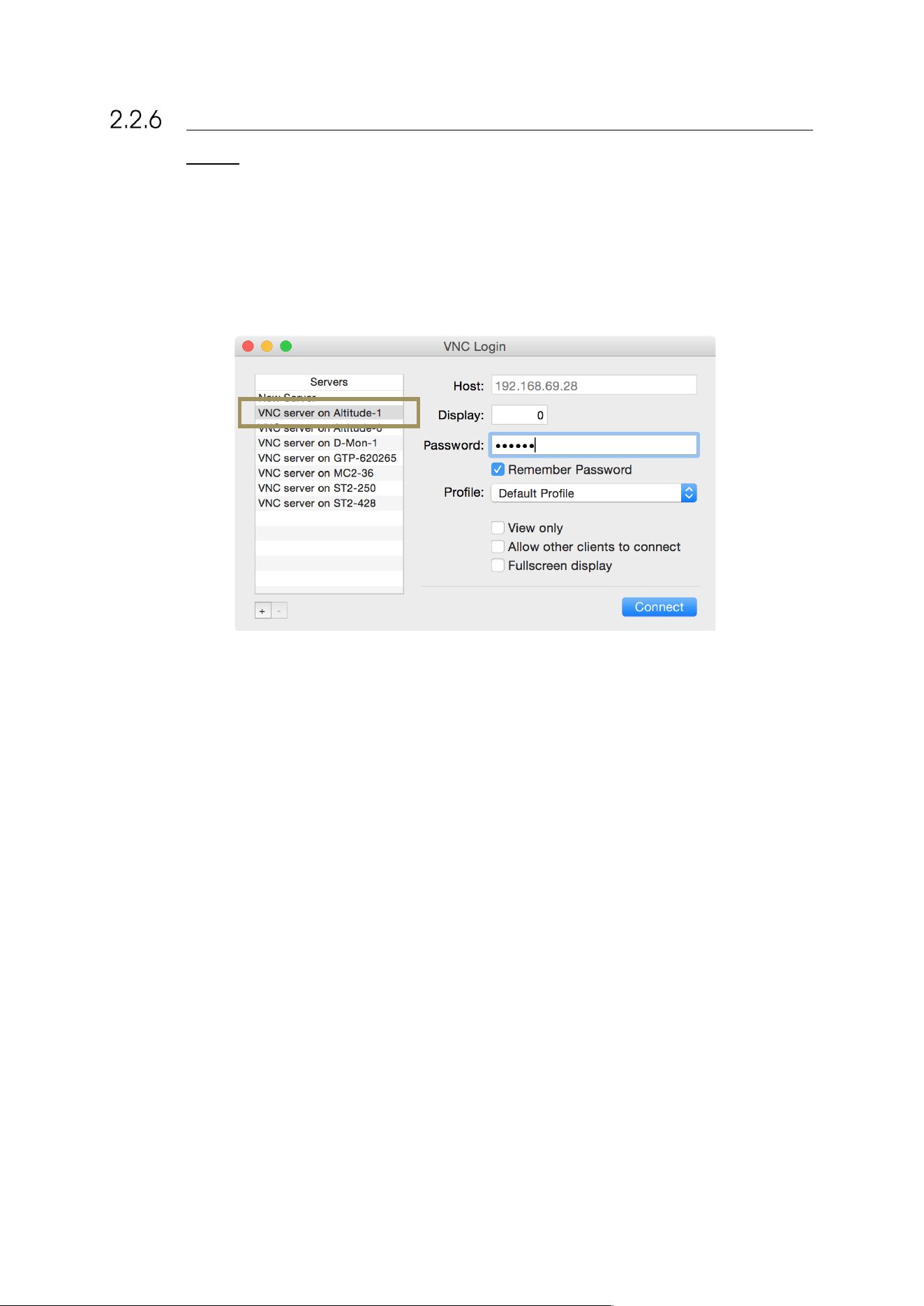
To connect to the SDP-75’s VNC Server with the Chicken of the VNC client from a Mac OS X computer:
1. Open the Chicken of the VNC software in your Mac OS X computer.
2. The VNC Login window shows a list of available VNC servers. Select the server “VNC server on SDP-75-XX”,
where XX is the number of your SDP-75.
Figure#22:#Chicken#of#the #V N C#Login#win d o w #
3. The Host’s IP address is automatically filled. You only need to enter the password, which is the six-digit serial
number of your SDP-75:
• the password is 00000X, if the number of your SDP-75’s VNC Server has a single digit;
• the password is 0000XX if the number of your SDP-75’s VNC Server has 2 digits;
• the password is 000XXX if the number of your SDP-75’s VNC Server has 3 digits;
• etc…
4. Click on the Connect button located in the lower left corner of the window.
5. The graphical user interface of your SDP-75 should now be visible on the screen of your Mac.
38
USING A WINDOWS COMPUTER WITH TIGHT VNC
Since Tight VNC is not a zero-conf client, the connection procedure requires some additional steps, which are described
below.
WRITE DOWN YOUR SDP-75’S SERIAL NUMBER
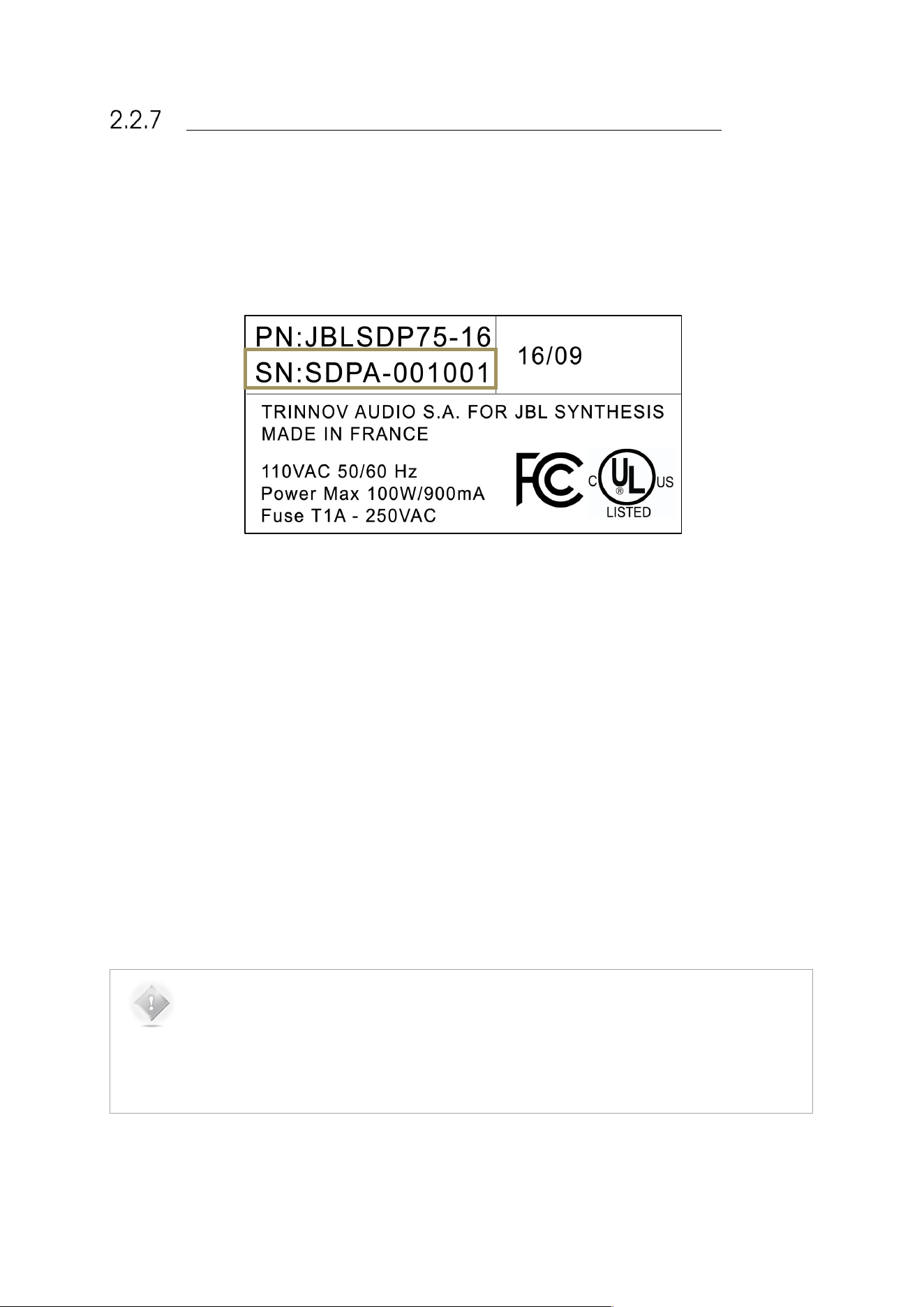
1. Go to your SDP-75’s back panel to find out its serial number. The 6-digit serial number is printed above the
MADE IN FRANCE tag: it is “123456” in the example below:
Figure#23:#a#serial#numb er #as #p rin te d #o n #t h e#b a c k #p a n el#o f #th e #SDP-75#
2. the VNC password is the six-digit serial number of your SDP-75:
• The password is 00000X, if the number of your SDP-75’s VNC Server has a single digit;
• The password is 0000XX if the number of your SDP-75’s VNC Server has 2 digits;
• The password is 000XXX if the number of your SDP-75’s VNC Server has 3 digits;
• Etc…
WRITE DOWN THE IP ADDRESS OF THE SDP-75
If your VNC client is not zeroconf-enabled it cannot find the SDP-75‘s VNC Server automatically. This is the case of the
Tight VNC client for Windows. Therefore, you’ll need to enter the SDP-75‘s IP address in the connection window. More
precisely, the IP address you need to enter is:
● The IP address of the Ethernet interface, if the SDP-75 is connected to the router via an Ethernet cable.
● The AP IP address of the Wi-Fi interface, if the remote device is connected to the Access Point of the SDP-75.
● The IP address of the Wi-Fi interface, if the SDP-75 is connected to an existing Wi-Fi network.
NOTE:
the IP address of the SDP-75 can be retrieved:
● via the front panel, in the Setup/Network/Ethernet page or in the Setup/Network/Wi-fi
page;
● from the Network page of the graphical user interface, displayed to a monitor via the VGA
or DVI port.
39
GETTING THE IP ADDRESS FROM
THE WI-FI SETTINGS
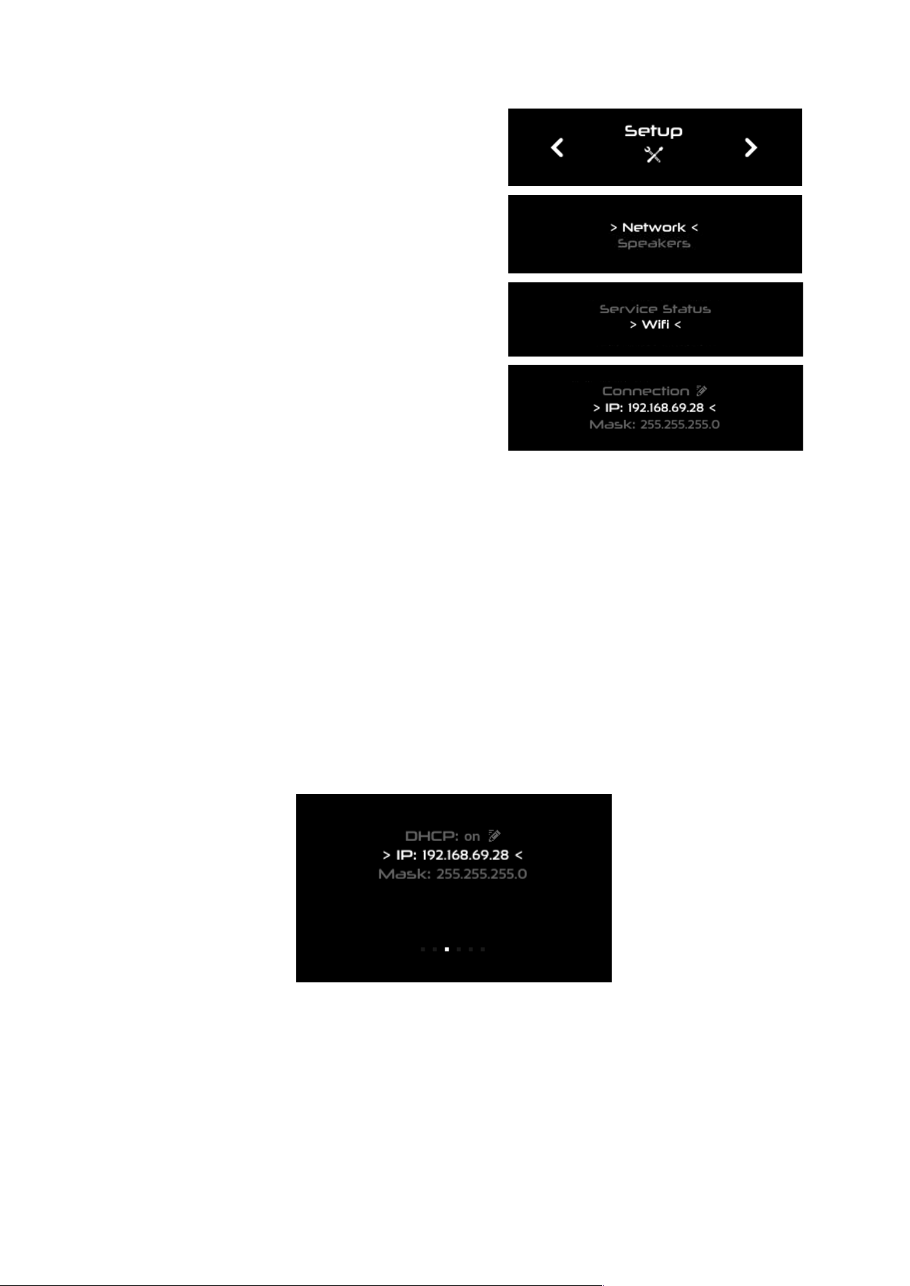
To get the IP address from the Wi-Fi settings via
the front panel:
Click on the menu button
Go to the Setup > Network > Wi-Fi page:
Turn the Source/Item selection knob to scroll
through the settings.
Figure#24:#IP#address#in#the#Setup#>#N e tw o r k# >#Wi-Fi#
page#via#the#front#panel#
GETTING THE IP ADDRESS FROM THE ETHERNET SETTINGS
● To get the IP address from the Ethernet settings via the front panel:
● Click on the menu button
● Select the Setup > Network > Ethernet page
● Turn the Source/Item selection knob to scroll through the settings.
Figure#25:#IP#address#in#the#Setup#>#Network#>#Ethernet#page#via#the#front#panel#
40
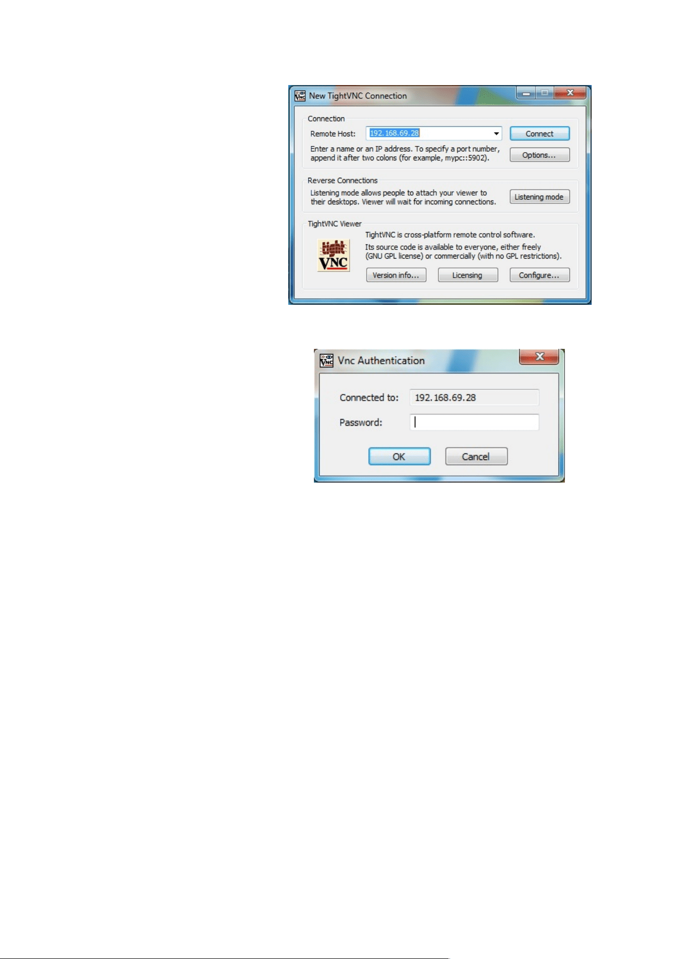
CONNECT WITH TIGHT VNC
First of all, use the SDP-75’s front panel
display to find out the IP address of its VNC
Server (see the detailed explanation above).
To connect with your VNC client to the SDP-
75:
1. Open the Tight VNC software in your
Windows computer.
2. In the VNC client’s connection window,
enter the IP address of the SDP-75’s
VNC Server (see the detailed
explanation above),
3. Click on the Connect button. This will
open the VNC Authentication window:
4. In the VNC Authentication window,
enter the password, which is the six-
digit serial number of your SDP-75,
printed on the back panel.
a. The password is 00000X, if
the number of your SDP-75’s
VNC Server has a single digit;
b. The password is 0000XX if
the number of your SDP-75’s
VNC Server has 2 digits;
c. The password is 000XXX if
the number of your SDP-75’s
VNC Server has 3 digits;
d. Etc…
5. Once you’ve entered the correct
password, the SDP-75’s graphical user
interface will be displayed.
#
Figure#26:#the#New#Tigh tV N C #C onnection #p a n e l##
on#a#Windows#computer#
41
2.3 CHANGING THE NETWORK SETTINGS
THROUGH THE FRONT PANEL
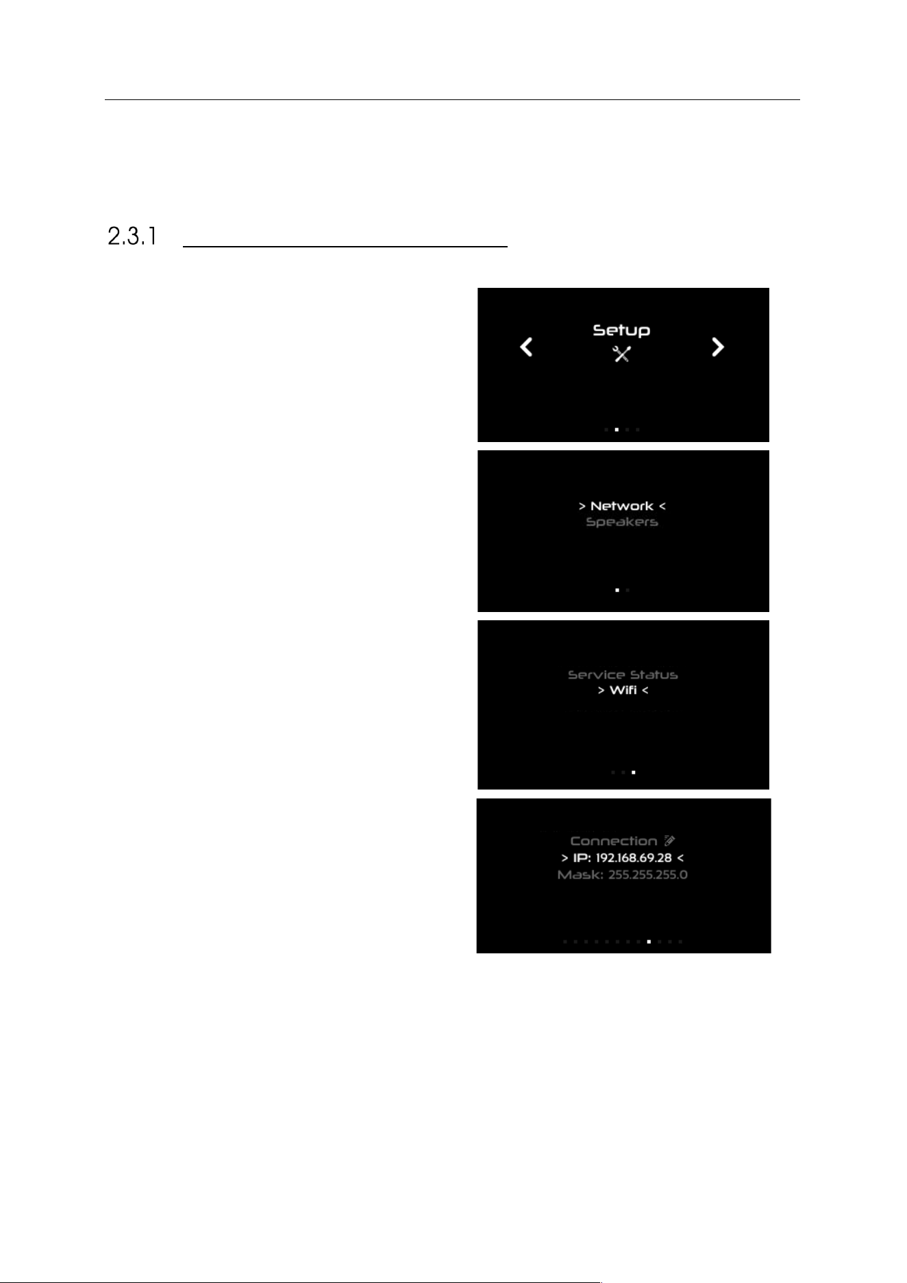
CHECKING THE WI-FI SETTINGS
To check the Wi-Fi settings via the front panel:
1. Click on the menu button
2. Go to the Setup > Network > Wifi page:
3. Turn the Source/Item selection knob to scroll
through the settings.
Figure#27:##
Setup#>#Network#>#Wi-Fi#page#via#the#front#panel#
42
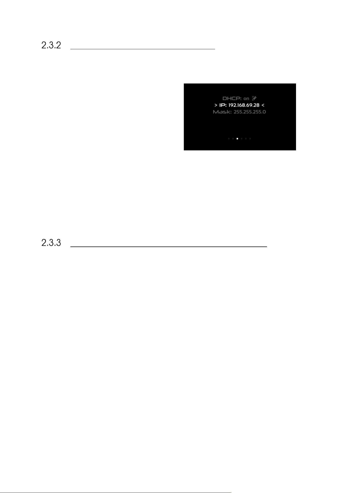
CHECKING THE ETHERNET SETTINGS
To check the Ethernet settings via the front panel:
1. Click on the menu button
2. Select the Setup > Network > Ethernet
page
3. Turn the Source/Item selection knob to
scroll through the settings.
Figure#28:##
Setup#>#Network#>#Ethernet#page#via#the#front#panel#
CONNECTING THE SDP-75 TO A WI-FI NETWORK
Please refer to Step 2 of the subchapter above.
43
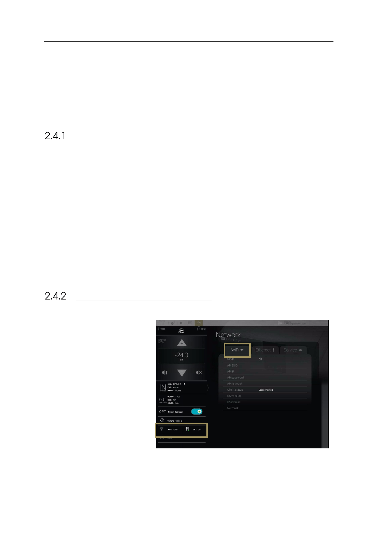
2.4 CHANGING THE WI-FI SETTINGS THROUGH
THE GUI
This subchapter explains how to change the Wi-Fi settings of the SDP-75 to meet the requirements
of your home theatre’s network environment.
ABOUT THE WI-FI INFORMATION
The following Wi-Fi information is available in the SDP-75:
● Mode: indicates the current Wi-Fi mode of the SDP-75.
● AP SSID: indicates the name of the SDP-75’s Wi-Fi Access Point.
● AP IP: indicates the IP address of the Access Point to be used for VNC connection when using the SDP-75 as
Wi-Fi Access Point.
● AP password: indicates the password to be used when attempting to join the SDP-75’s Wi-Fi Access Point.
● AP netmask: indicates the netmask of the SDP-75’s Wi-Fi Access Point.
● Client status : indicates the status of the Wi-Fi client of the SDP-75.
● Client SSD: indicates the name of the Wi-Fi Network joined by the SDP-75 as a Wi-Fi client. None displayed if
no connection has been established.
● IP address: indicates the IP Address of the Wi-Fi client.
● Netmask: indicates the netmask of the Wi-Fi Network joined by the SDP-75 as a Wi-Fi client.
CHECKING THE WI-FI SETTINGS
The Wi-Fi network information can be
retrieved from the Graphical User
Interface of the SDP-75:
#
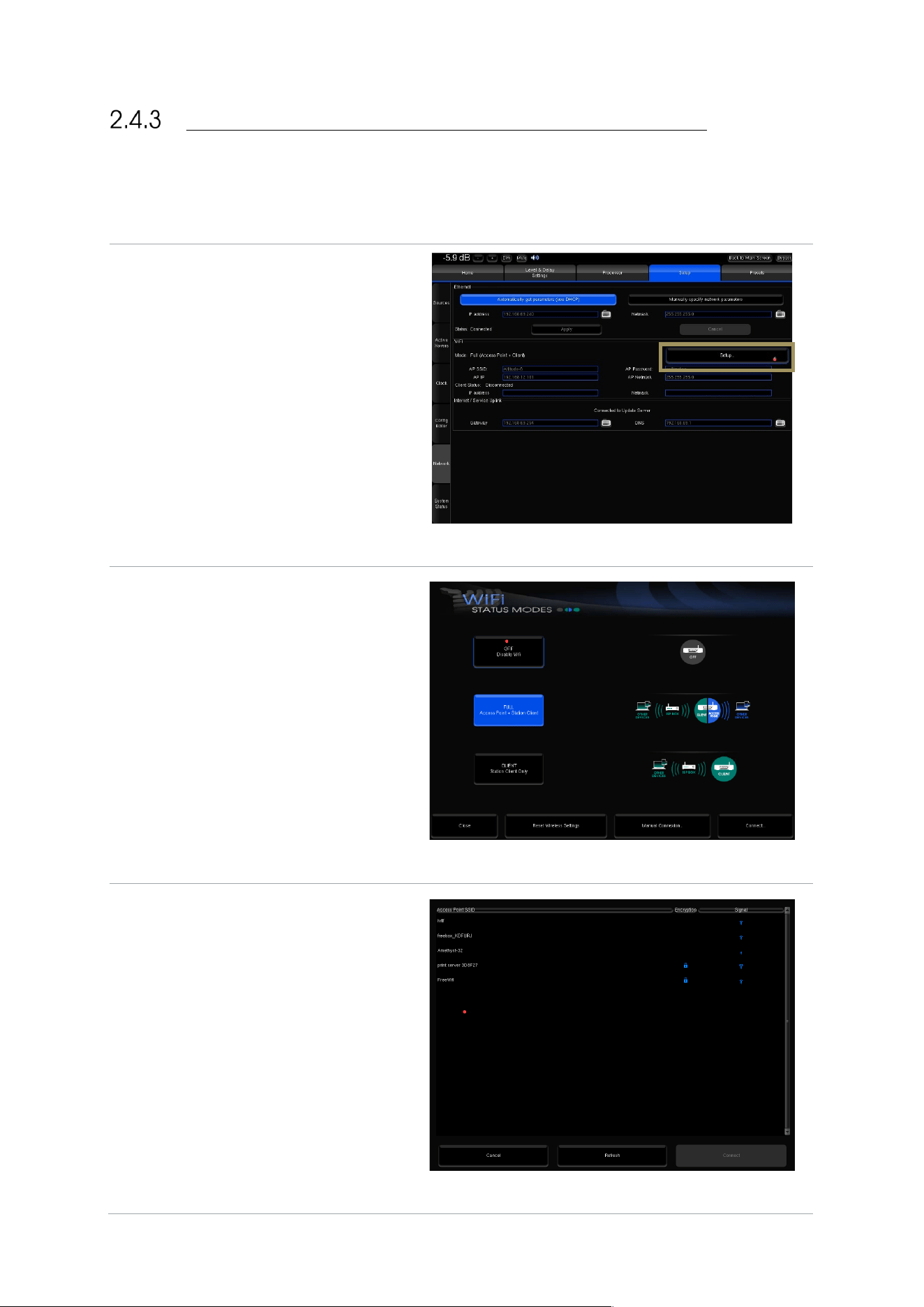
44
CONNECTING THE SDP-75 TO A WI-FI NETWORK
The most flexible network option for the final installation of your SDP-75 is to connect it as a Wi-Fi client to your existing
Wi-Fi network. This will allow you to connect to the SDP-75 and to the Internet simultaneously, without switching back
and forth between two different Wi-Fi networks.
To connect the SDP-75 to an existing Wi-Fi
network:
● Open the Advanced Settings user
interface.
● Go to the Setup/Network page.
● In the Wi-Fi section, click on the
Setup... button. This opens the Wi-
Fi Status Modes page.
Figure#29:#the#Setup/Ne twork#page#
• Click on the Connect... button in
the bottom right corner of the
page. This will display the
available Wi-Fi networks. The
encryption column displays a lock
icon when the network is
protected by a passphrase and/or
encrypted. The signal column
displays a Wi-Fi signal icon,
indicating the strength of the Wi-
Fi signal
#
Figure#30:#Wi-Fi#status#modes#page#
• Select the Wi-Fi network you want
to join, and click on the Connect
button. If you select an encrypted
Access Point, you will be asked for
the passphrase.
• Enter the passphrase and press
the OK button.
Your SDP-75 should now be
connected to the chosen Wi-Fi
network.
#
Figure#31:#list#of#available#Wi-Fi#networks#
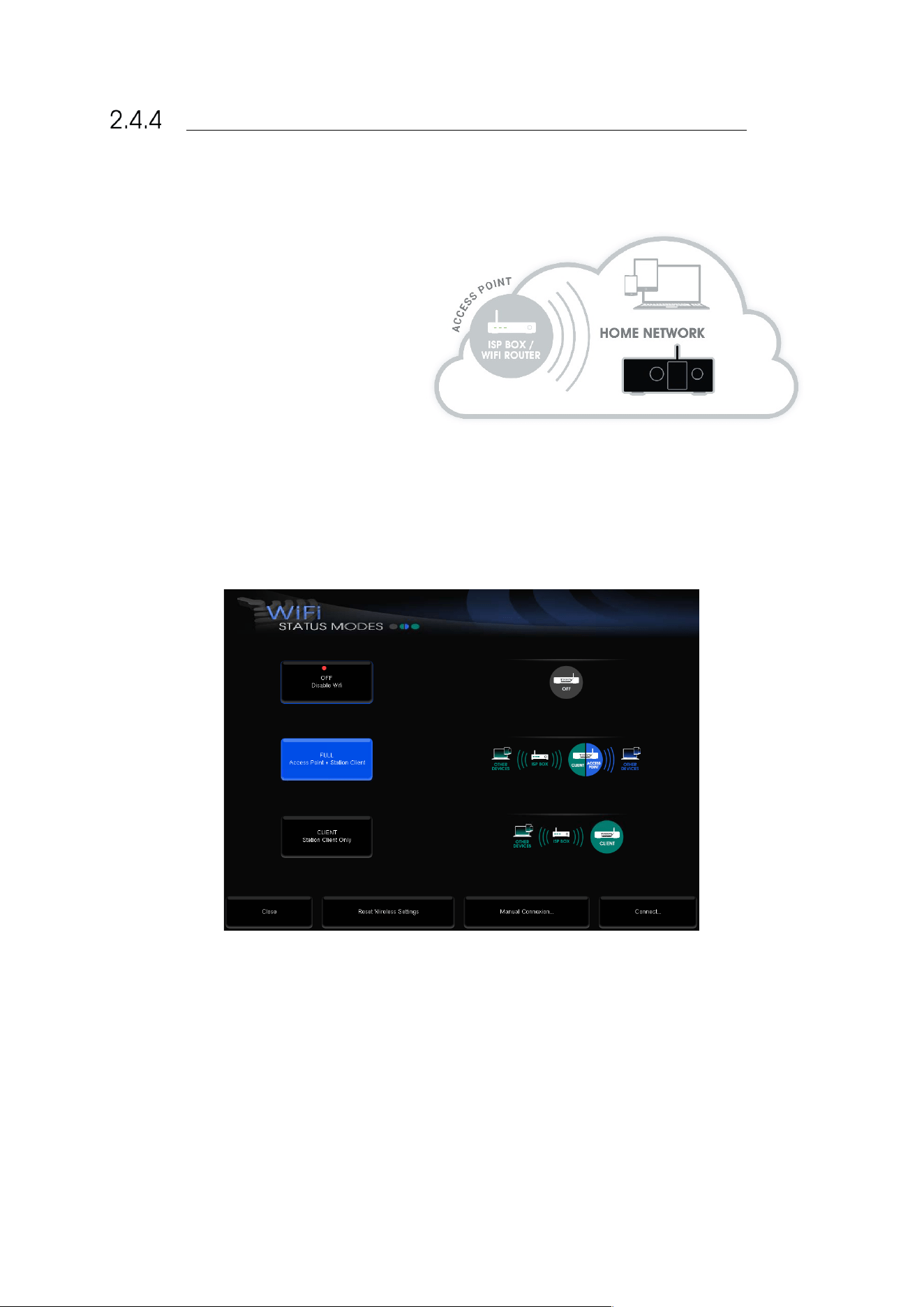
45
CHANGING THE WI-FI STATUS MODE OF THE SDP-75
The SDP-75‘s built-in Wi-Fi and Ethernet modules allow it to simultaneously be part of a network as:
• An Ethernet client connected to an
existing Ethernet network through an
ISP Box (Internet Service Provider) or a
router.
• A Wi-Fi Access Point (AP) to create its
own Wi-Fi network.
• A Wi-Fi client to join an existing
network wirelessly.
To change the Wi-Fi settings of your SDP-75 via the graphical user interface:
1. Open the Advanced Settings interface;
2. Go to the Setup/Network page:
3. Press the Setup… button to display the Wi-Fi Status Modes page:
Figure#32:#Wi-Fi#Status#modes#
You can choose one of the following Wi-Fi modes:
• OFF: the Wi-Fi module of the SDP-75 is disabled.
• FULL (default): the SDP-75 is used both as an Access Point and as a Client.
• CLIENT: the Access Point is disabled but the SDP-75 still operates as a Wi-Fi client as long as the configuration
is valid.
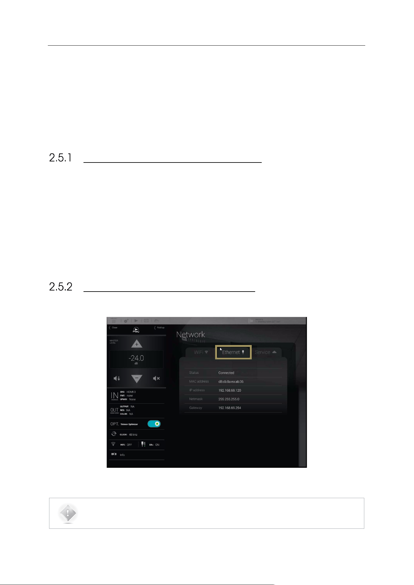
46
2.5 CHANGING THE ETHERNET SETTINGS
THROUGH THE GUI
This subchapter explains how to change the Ethernet settings of the SDP-75 to meet the
requirements of your home theatre’s technical environment.
ABOUT THE ETHERNET INFORMATION
The following Ethernet information is available in the SDP-75:
• Status: indicates the connection status of the Ethernet interface of the SDP-75
• MAC address: indicates the MAC address of the network interface of the SDP-75 (required to remotely switch
the SDP-75 on with a Wake-on-Lan command).
• IP address: indicates the IP address of the Ethernet interface of the SDP-75.
• Netmask: indicates the netmask of the local area network joined as a DHCP client via Ethernet.
• Gateway: indicates the address of the Gateway for network interconnection.
CHECKING THE ETHERNET SETTINGS
The network information can be retrieved from the Graphical User Interface of the SDP-75:
Figure#33:#Ethernet#Netw o r k#In t erf a ce #In fo rmation#
NOTE: Network settings can only be changed through the Advanced Settings interface of the SDP-75.
Go to the Setup/Network page to change the Ethernet and Wi-Fi settings.
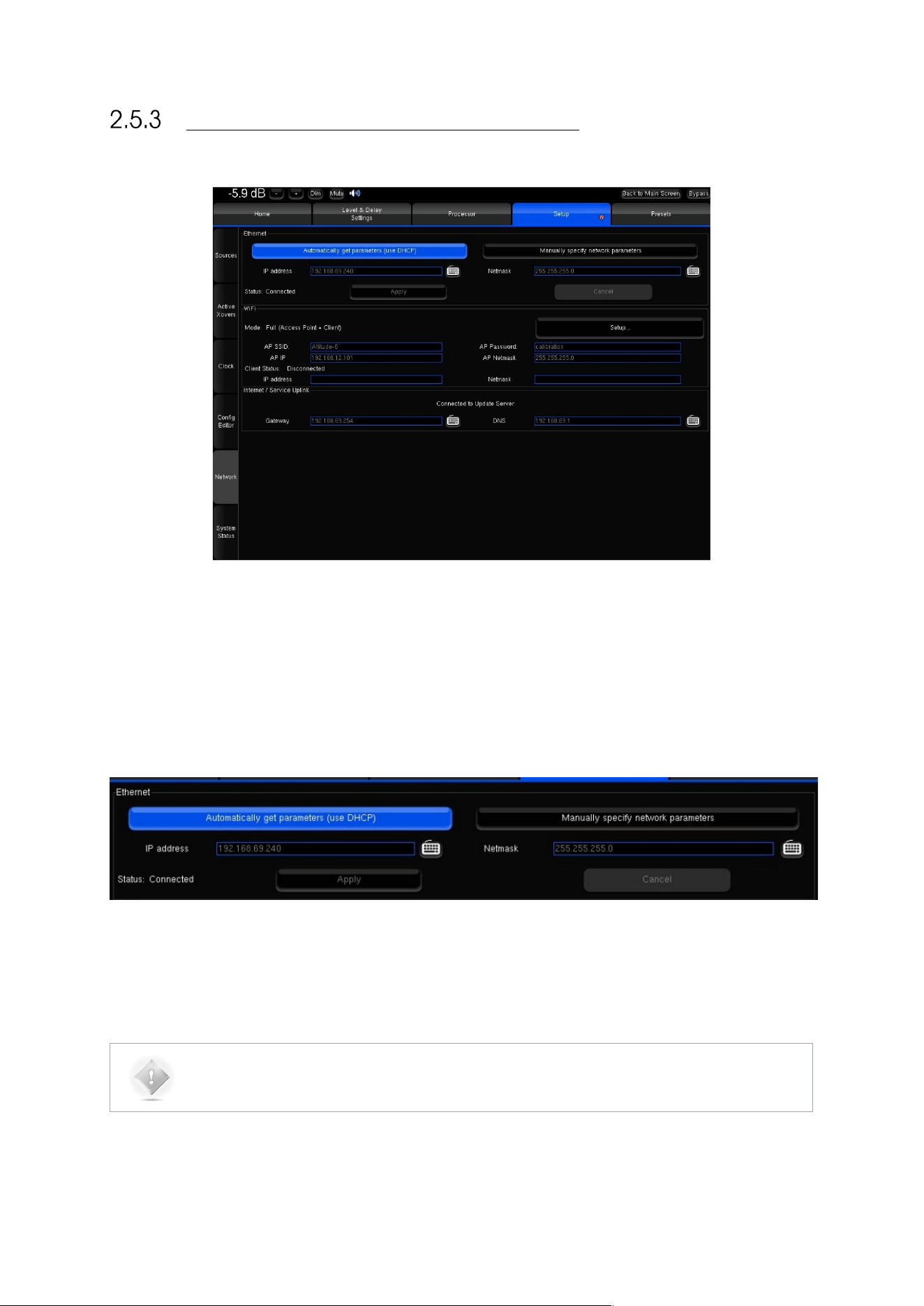
47
CHANGING THE ETHERNET SETTINGS
Figure#34:#Network#Setu p #in #the#Advan ce d #S et tin g s#menu#
The default mode of the Ethernet interface of the SDP-75 is DHCP, meaning that the SDP-75 will automatically be
detected and configured by the router, provided that the router runs a DHCP server. This is the case in most domestic
environments.
To configure the Ethernet connection manually, select the Manually specify Network parameters option and hit the
Apply button.
The IP address, Netmask, Gateway and DNS option can then be edited manually.
Applying new settings with the Apply button is required for every change.
NOTE: It is recommended to refer to an IT specialist before switching to manual configuration.
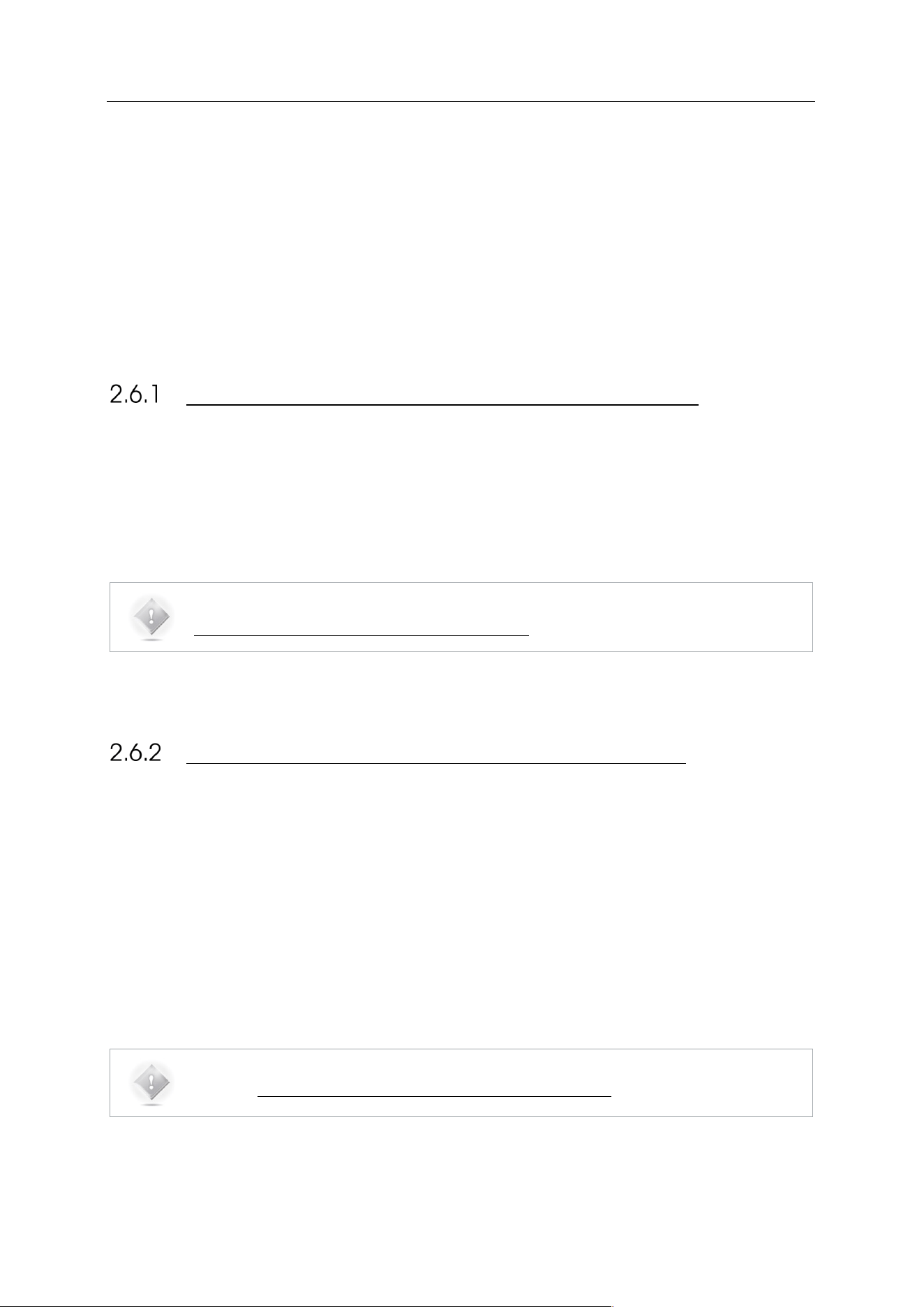
48
2.6 ABOUT VNC AND ZERO-CONF
NETWORKING
The SDP-75 leverages two important networking technologies: VNC and zero-configuration
networking, which are explained below.
ABOUT VNC (VIRTUAL NETWORK COMPUTING)
VNC is a graphical desktop sharing system that transmits the keyboard and mouse events from one computer (server)
to another (client), relaying the graphical screen updates back in the other direction, over a network.
The SDP-75 has a built-in VNC Server that allows you to access its graphical user interface over a network from any
device running a VNC client.
In other words, you can control the SDP-75 from any device, whether it’s a computer (PC, Mac or Linux) or a tablet (iOS,
Android or Windows), provided that both the SDP-75 and your device are part of the same network.
NOTE: to learn more about VNC, please read the following article on Wikipedia:
http://en.wikipedia.org/wiki/Virtual_Network_Computing
ABOUT ZERO-CONFIGURATION NETWORKING
Zero configuration networking (zeroconf) is a networking technology that makes it easy to set up and use devices and
services on a network. Because zeroconf-enabled devices indicate their availability, it’s easy for you (or an app or service)
to find devices and services that you want to use.
The SDP-75’s VNC Server is zeroconf-enabled in order to indicate its availability to the zeroconf-enabled VNC Client
running on your device (tablet or computer).
The two major implementations used in VNC client apps are:
• The Bonjour protocol, developed by Apple Inc. It is available in free VNC clients such as Mocha VNC Light (for
iOS and Android devices) and Chicken of the VNC (for Mac OS X).
• Avahi, for the Linux operating system.
Microsoft has its own proprietary protocol for remote computing: RDP (Remote Desktop Protocol). This explains why
there is no major implementation of the zeroconf technology on the Windows platform.
NOTE: to learn more about Zero-configuration networking, please read the following article on
Wikipedia: http://en.wikipedia.org/wiki/Zero-configuration_networking
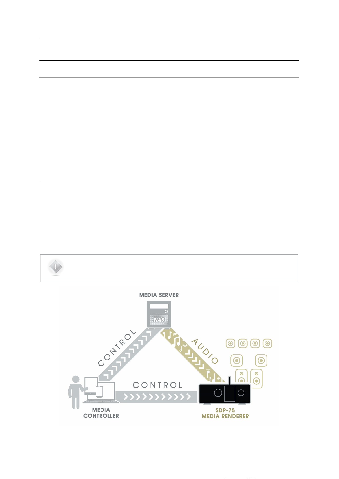
49
3 NETWORK STREAMING
3.1 THE UPNP PROTOCOL
The SDP-75 network streamer feature is based on the Universal Plug and Play (UPnP) set of networking protocols. In
the UPnP/DLNA terminology, the SDP-75 is a UPnP Digital Media Rendering device and is used as secondary
equipment to play media content sent through the network.
The SDP-75 must be used with DLNA/UPnP compatible server and controller devices. The Media Server shares its
media library on the network with UPnP clients. The Media Controller is the primary device, used to automatically detect
servers and play files on secondary devices as well as to control them.
Provided that the server supports these formats, the SDP-75 can decode and play high-resolution 24 bit/192 kHz WAV,
AIFF, FLAC and 16 bit/192 kHz OGG music files.
3.2 UPNP NETWORK ARCHITECTURE
This architecture represents the most common and comfortable method to play media files in a domestic environment:
• A Network-Attached Storage (NAS) or a computer is used as UPnP server and shares the media library.
• The library is browsed from a Media Controller, installed on a tablet or smartphone.
• The SDP-75 is selected as rendering device from the Media Controller.
NOTE: Most NAS are UPnP compatible servers but any computer can be turned into a server provided
that a compatible UPnP server software is installed.
Several applications can turn smartphone and tablets into media controllers or servers.
UPnP#Network#with#a#Digital#Media#Controller#
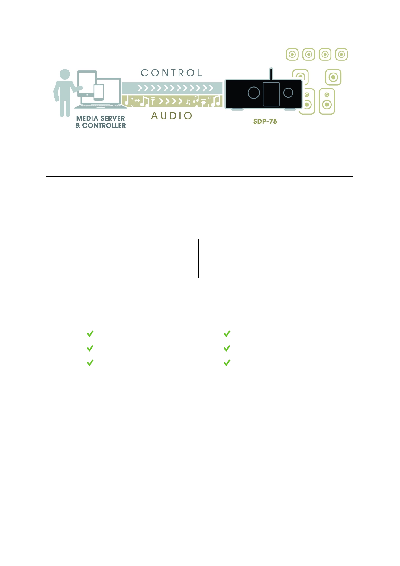
50
#
UPnP#Network#with#a#device#used#as#server#and#controller#
3.3 RECOMMENDED UPNP SOFTWARE
“These software platforms have been selected, tested and qualified based on the following requirements.
JRiver
MediaCenter
PS Audio
eLyric Music Manager
These software has been selected, tested and qualified based on the following requirements.
UPnP server and controller
24 bits 192 playback
Bit Perfect Streaming
WAVE AIFF FLAC OFF support
Album cover art display
User-friendly graphical user interface
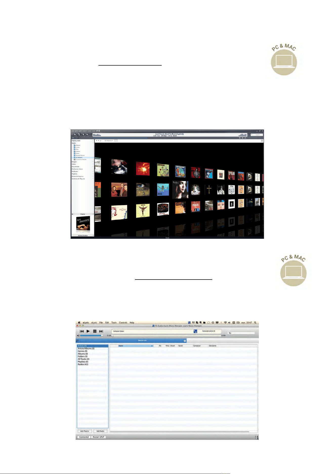
51
JRiver
MediaCenter (www.jriver.com)
JRiver Media Center is a comprehensive media player and UPnP platform that can be used as both server
and controller.
This software is therefore well-suited to the SDP-75.
JRiver Media Center is a commercial software available for PC and Mac.
D
O
W
NL
O
A
D
>
www.
j
r
i
v
e
r
.
c
om
/
do
wn
l
o
a
d
.h
t
m
l
PS Audio
eLyric Music Manager (www.psaudio.com)
eLyric Music Manager is a free alternative media manager developped by PS Audio.
A
l
s
o a
v
a
il
ab
l
e
f
o
r
W
i
ndow
s
®
and
M
ac
,
i
t
can b
e
u
s
e
d a
s
bo
t
h U
P
n
P
s
e
r
v
e
r
and con
t
r
o
ll
e
r
.
D
O
W
NL
O
A
D
>
www.
p
s
a
u
d
i
o
.
c
om
/
p
r
od
u
c
t
s
/
a
u
d
i
o
/
e
l
y
r
i
c
-
m
a
n
a
g
e
r
Server#
&#
Controller#
Server#
&#
Controller#

52
4 DAILY OPERATIONS
This chapter explains how to perform daily operations on the SDP-75 such as:
Volume control / Source selection / Preset selection…
These operations can be performed:
Via the front panel / Via the IR remote control / Via the graphical user interface.
4.1 AVAILABLE USER INTERFACES
Simple daily operations on the SDP-75 can be performed:
• On the front panel, by turning the Source/Item selection knob and pushing the Select button to scroll through
the menus;
• With the infrared remote control,
• From your tablet or your computer, connected to the same network as the SDP-75:
o with a VNC Client connected to the SDP-75 ‘s VNC Server,
o with a web browser accessing the SDP-75’s web-based interface,
• With a display, a mouse and a keyboard directly connected to the SDP-75’s back panel.
NOTE:
• For a detailed step-by-step explanation of how to connect with a VNC Client, please see the
subchapter First Network Connection to the SDP-75 in the Network Setup chapter.
• Further details about the web interface are provided in the Introduction chapter of this
document.
• For additional details about connecting a display, a mouse and a keyboard, please refer to the
Introduction chapter at the beginning of this document.
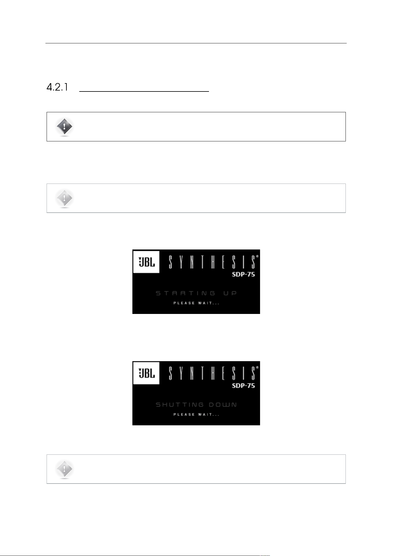
53
4.2 USING THE FRONT PANEL
POWER ON-OFF SEQUENCE
IMPORTANT NOTE: don’t forget that the amplifiers should always be powered-on last.
Turn On the main power switch on the rear panel to supply the SDP-75 with power, then press the front panel power
button to start the SDP-75.
NOTE: The system doesn’t start instantly and takes about 60 seconds to complete its start-up.
While the system starts, the front panel screen displays the following image:
Figure#35:#Front#panel#startup#imag e #
To shut the SDP-75 down, press the front panel power button once. The front panel screen will then display the
following image until a complete shutdown.
Figure#36:#Front#panel#shut#dow n#im a ge #
NOTE: It is not recommended to cut the AC Power via the main power switch on the rear panel, as the
system saves several “last-used” settings while shutting-down.
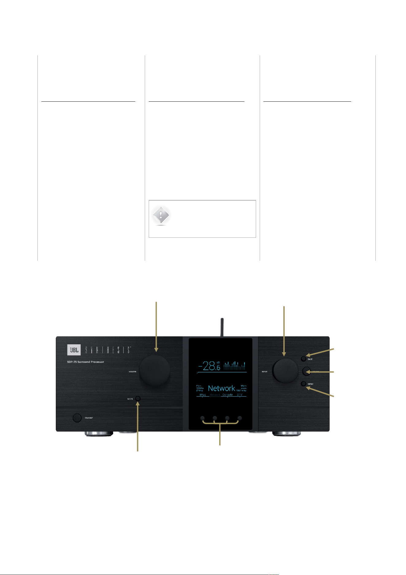
54
VOLUME CONTROL
• Turning the Volume Control knob to
the right or left will respectively turn
the volume up or down.
• Push the Mute button to mute all audio
outputs of the SDP-75.
SOURCE SELECTION
There are two methods to select sources
from the front-panel on the SDP-75:
• Turn the source selection knob
to scroll through sources and
push the select button.
•
• Use one of the direct selection
buttons to choose among the
first four sources (also available
on the remote control).
NOTE: With factory
settings, the last-used
source is recalled on start-
up.
PRESET SELECTION
In order to select a preset through the
front-panel menus:
1. Push the Menu button, scroll until Presets
and push the Select button.
2. Select the required preset using the
Source Selection Knob and push the
Select button.
Mute button
Volume control
knob
Source/item
selection knob
Back button
Select button
Menu button
Direct selection
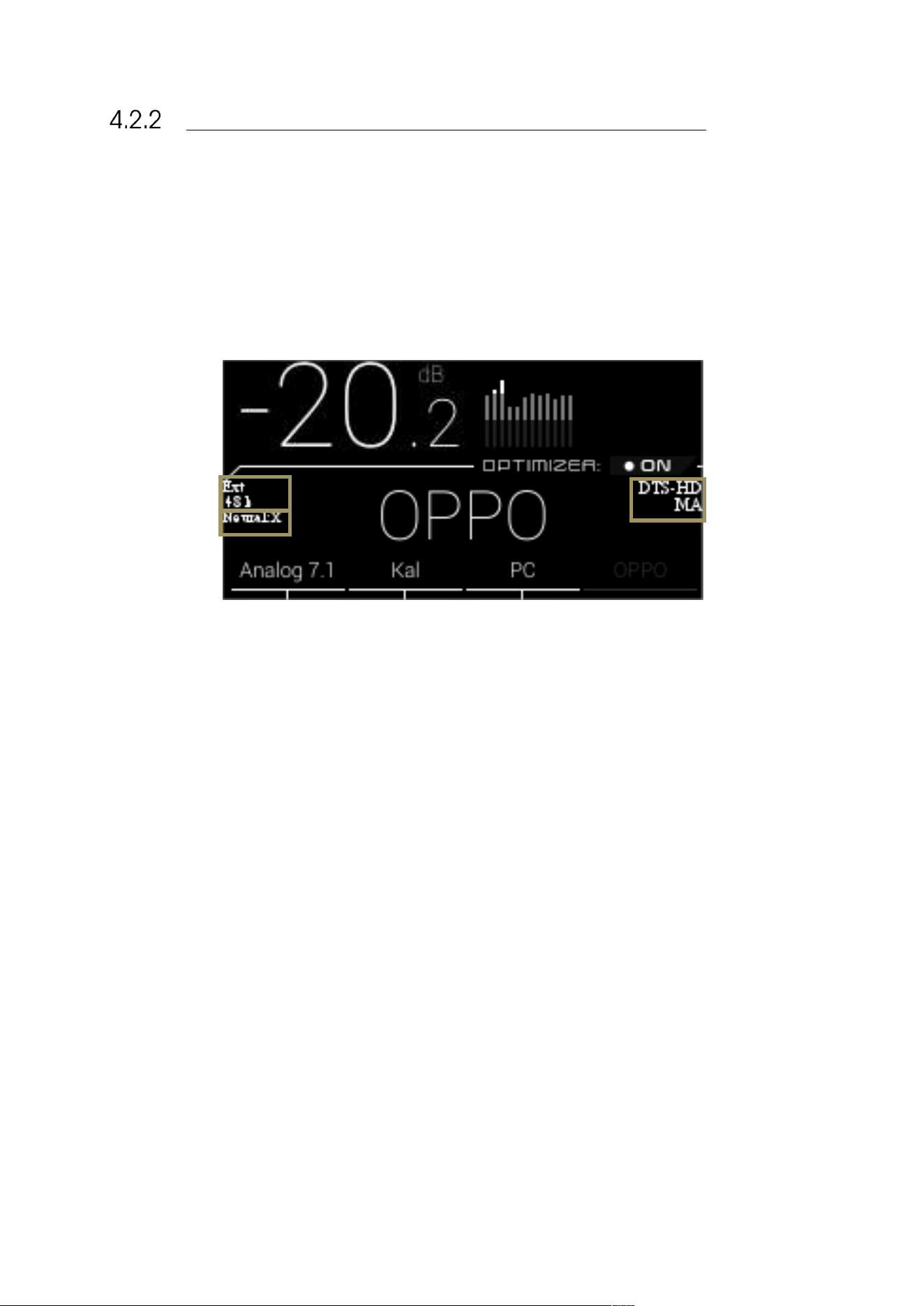
55
CHECKING THE FORMAT OF INCOMING AUDIO
The format of the incoming audio of the currently selected source is displayed on the front panel
display of the SDP-75 below the Optimizer status.
The Sampling Rate of the audio being played is indicated on the left side of the front panel display of
the SDP-75.
The current up-mixer used is displayed on the front panel display on the SDP-75 below the sampling
rate.
Figure#37:#SDP-75#front#panel#display #
Clock source &
sampling rate
Curent Up-
mixer
Curent
Format
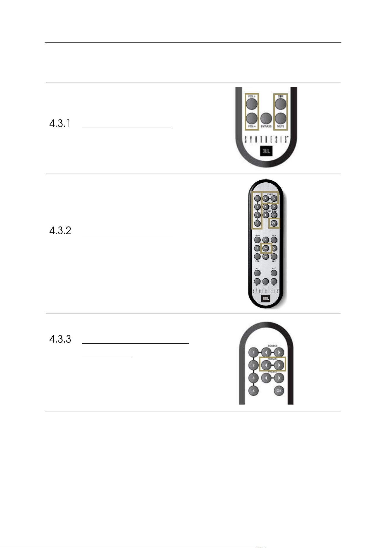
56
4.3 USING THE IR REMOTE CONTROL
VOLUME CONTROL
The following volume control buttons are available on the
IR Remote control
SOURCE SELECTION
The IR remote control includes 4 buttons for direct
source selection, as well as 2 buttons to browse through
the sources
LISTENING FORMAT
SELECTION
These allows you to switch between the different
listening format, and so between the different Up-mixers.
This can be done on the fly, you do not need to press OK
to validate.
Dim and
Mute
buttons
Volume Up
and Down
buttons
Direct Sources
selection
(instantaneous)
Browse through
Sources…
…and confirm with
‘OK’ button
Switch among the
listening formats
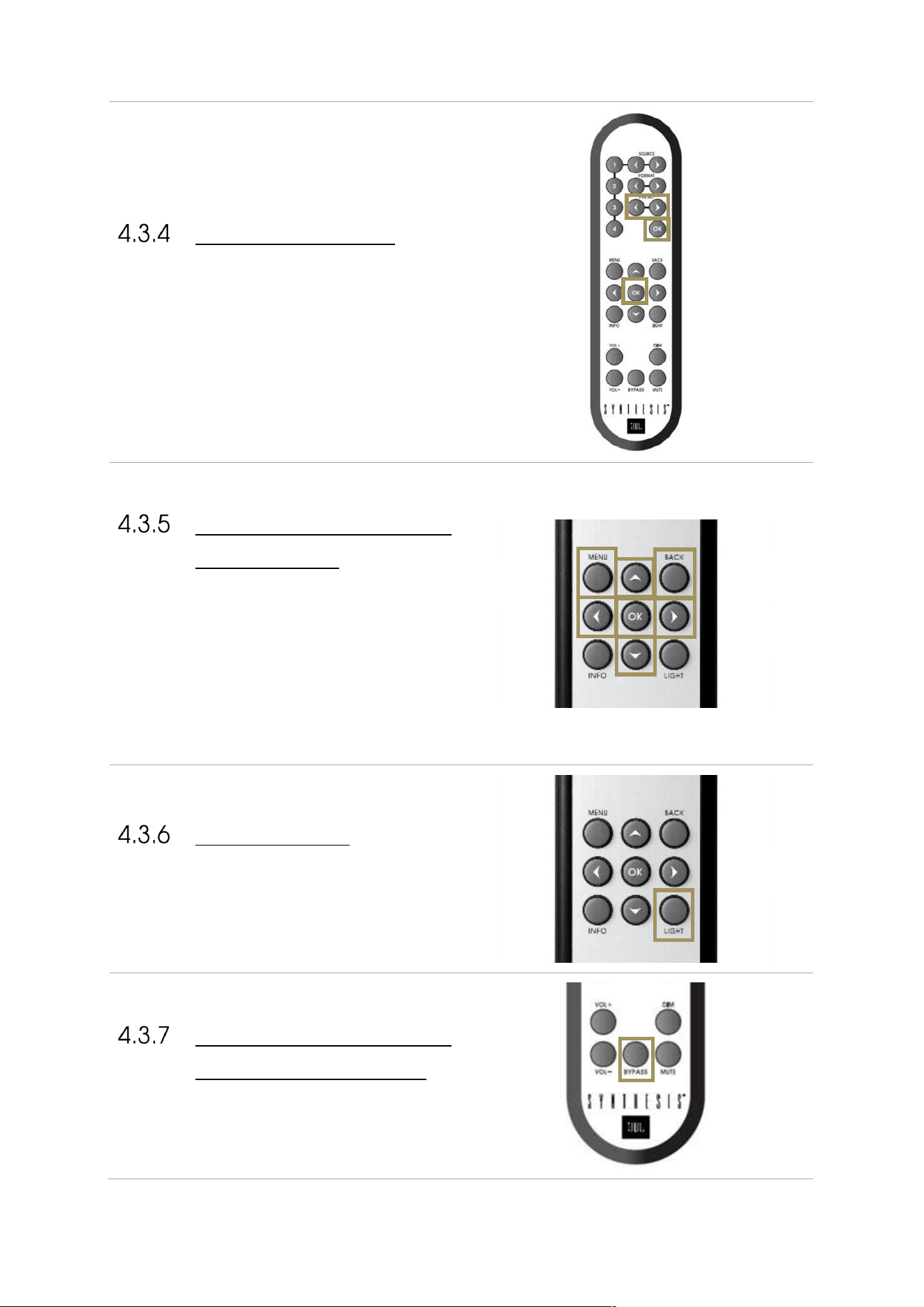
57
PRESET SELECTION
To switch to another preset:
1. Browse through the presets with the Preset arrow
buttons
2. Push the OK button.
ACCESS TO THE FRONT
PANEL MENU
To access to the Menu :
1. Press on Menu button to access to the Menu
2. Browser with
!
Left,
"
Right,
#
up and
$
down
arrows
3. Validate with the OK button
4. Return with the Back button
LIGHT BUTTON
The Light button allows to turn off the front panel
screen’s backlight. Pressing on another button will
temporarily turn on the backlight to let you know the
settings you are changing. Pressing the Light button will
turn the backlight on again.
LEVEL AND DELAY
ADJUSTMENT BYPASS
The Bypass button allows you to toggle on and off the
Optimizer.
Browse through
Presets…
…and confirm with
‘OK’ button
Access to the
Menu…
…Browse with the
arrows…
…
Confirm
with OK
Return with Back
Button
Turn off or on the
backlight
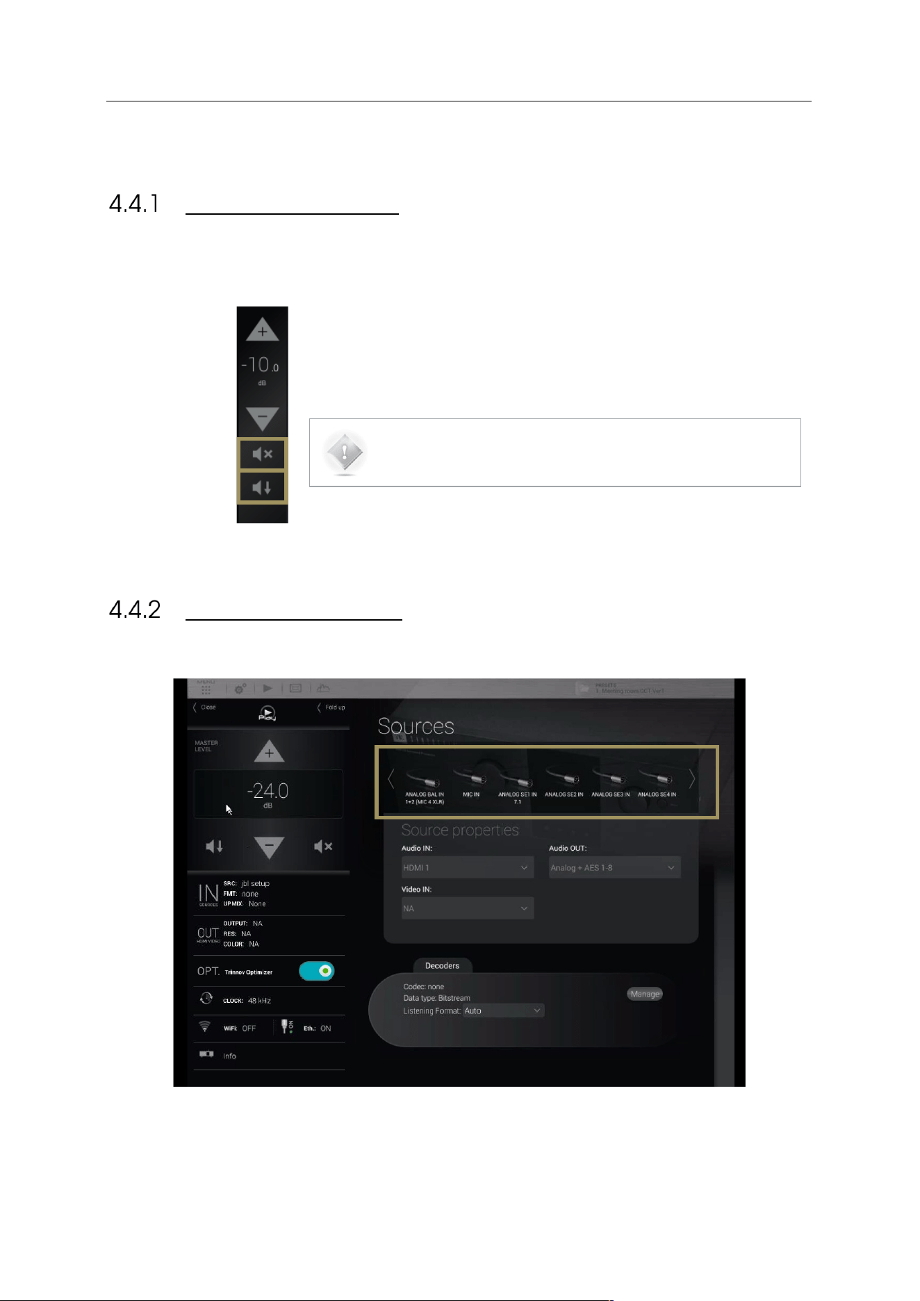
58
4.4 USING THE GRAPHICAL INTERFACE
VOLUME CONTROL
The following volume control options are available within the graphical user interface.
A Mute button also allows you to mute all audio outputs of the SDP-75.
A Dim button also allows you to decrease the volume by 20dB.
NOTE: By default the last used volume is recalled at start-up.
SOURCE SELECTION
Sources can be selected through the graphical user interface by clicking on the icon:
Figure#38:#The#source#selection#page#in#the#graphical#user#interface#
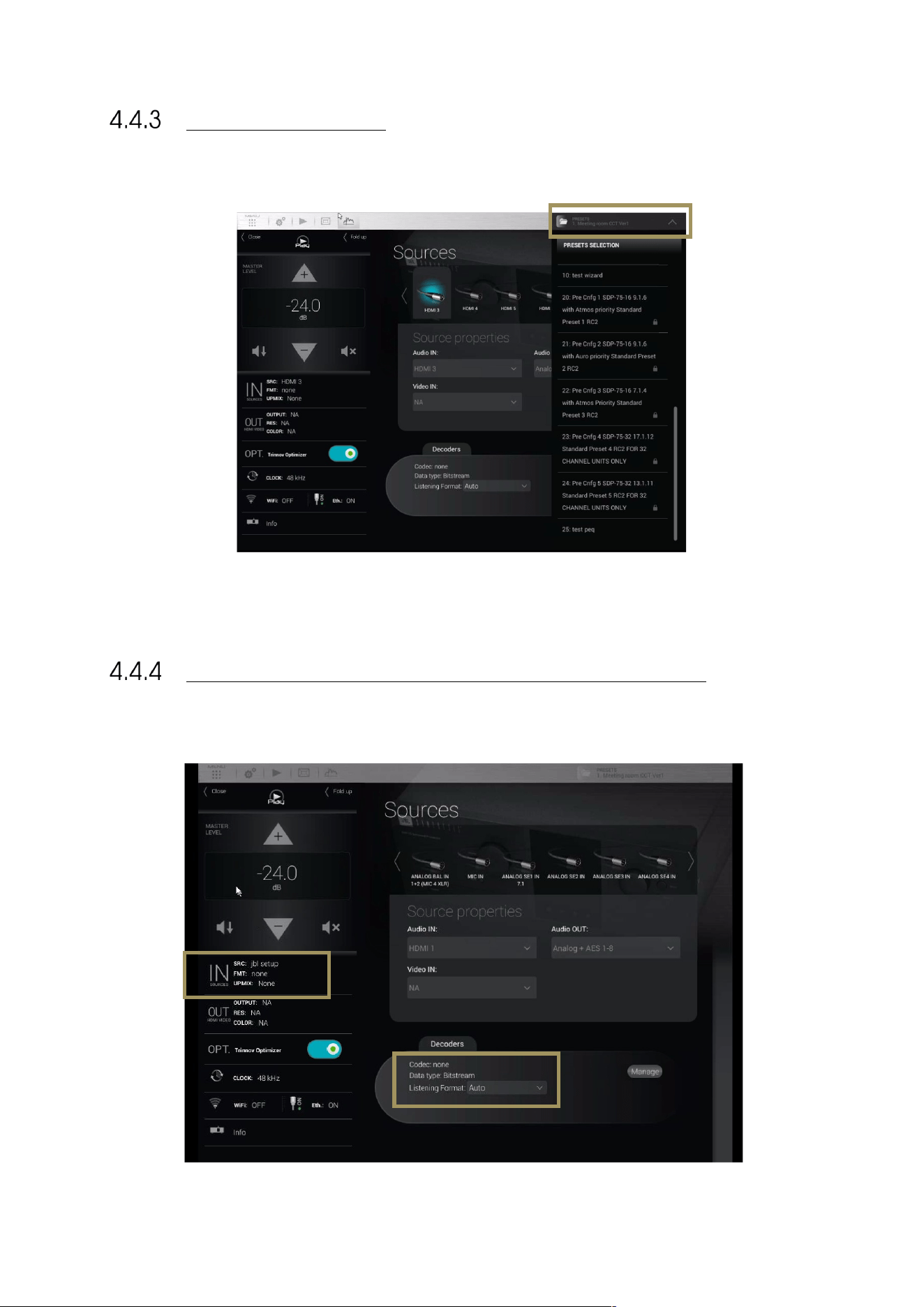
59
The Presets button
unfolds the presets
menu
Click on a Preset to
recall it
PRESET SELECTION
Presets can be selected through the graphical user interface:
Figure#39:#preset#selection #in #th e #gr aphical#user#in te rfa c e #
CHECKING THE FORMAT OF INCOMING AUDIO
The format of incoming audio is displayed in the lateral menu bar and in the Sources page of the Main user interface:
Figure#40:#checking#the#a u d io #fo r m a t#via#th e#us er#interfa ce#
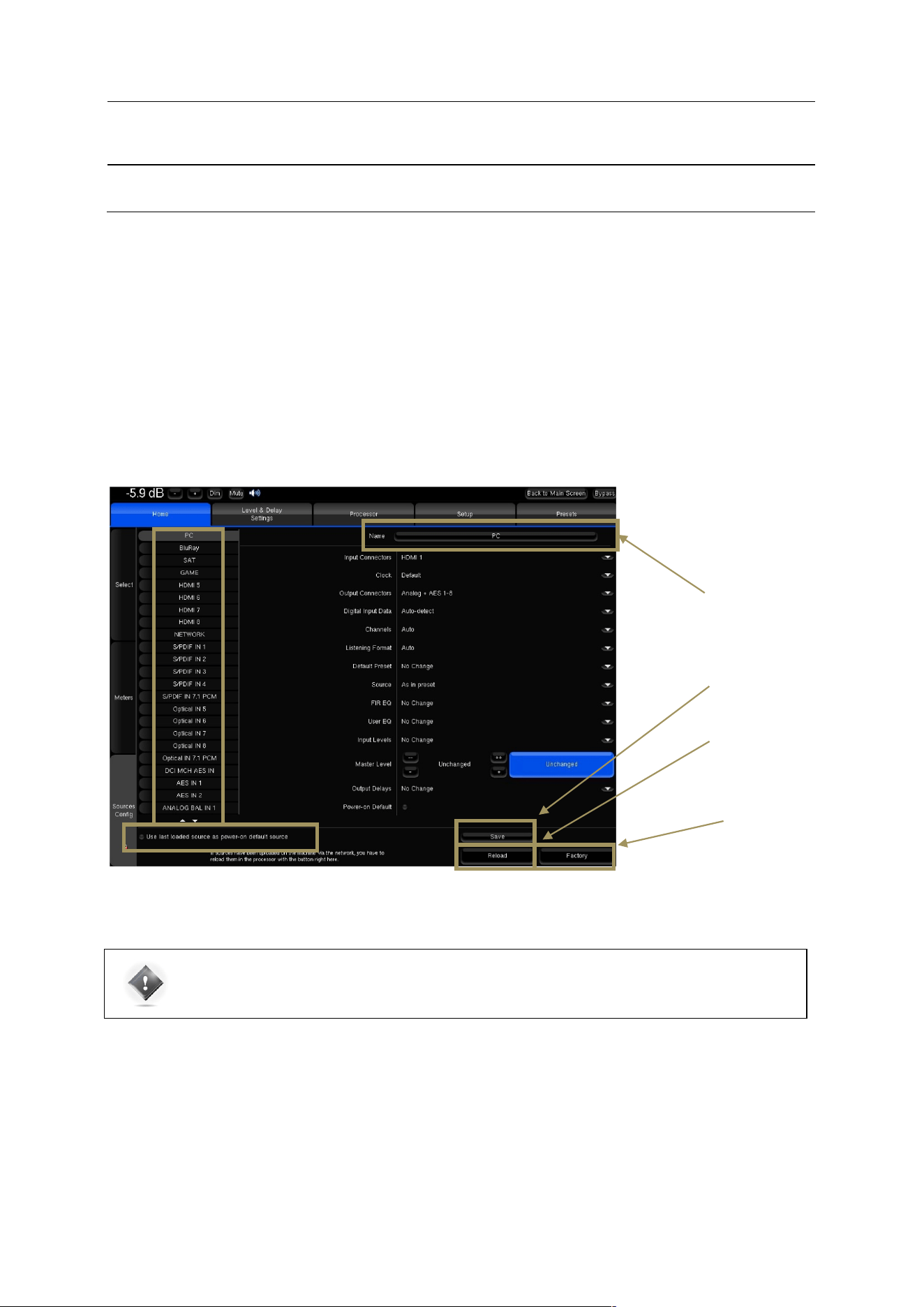
60
5 BASIC SETTINGS
5.1 NAMING YOUR SOURCES
The SDP-75 provides very flexible Source Configurations. Each Source Configuration can be renamed to reflect the actual
source to which is corresponds. By default, the source names correspond to the names of the back panel connectors
but can be edited in the Home/Sources Config page of the Advanced Settings Interface.
A Source Configuration can also include specific output and processing parameters. Therefore, it can be used to switch
between outputs or between different processing settings. For example, it is possible to configure two Source
Configurations set on the same inputs but set with different names to recall different settings.
The Home/Source Config page consists of one vertical tab per source on the left and source-specific parameters on
the right.
Figure#41:#Source#Conf igu r at io n#panel
IMPORTANT NOTE: It is particularly important to define user friendly names for the first four sources
because they are displayed on the front panel screen, and can be recalled from the front panel or from
the IR remote control source selection buttons.
Click on the source
name to edit
Click on the Save button
to save new settings
Click on the Reload
button to restore the
previously saved
settings
Click on the Factory
button to restore all
sources to the factory
default.
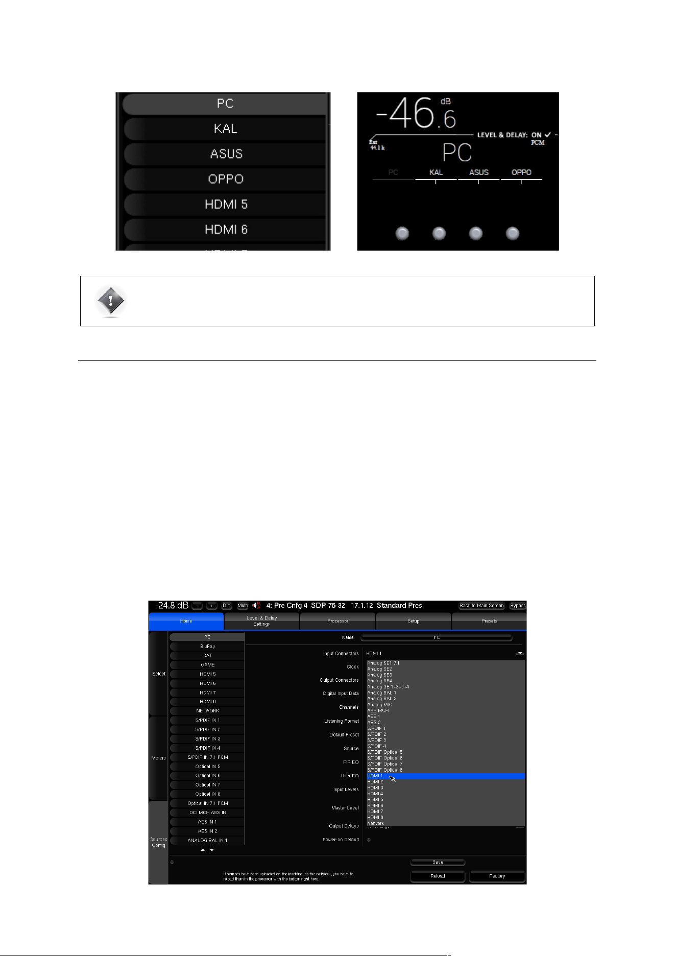
61
IMPORTANT NOTE: Changes are not applied until saved via the Save button in the bottom right corner
of the screen.
5.2 CONFIGURING YOUR SOURCES
In addition to an editable name, each Source Configuration includes several parameters to specify all the settings related
to a specific configuration requirement for your system.
Source configurations can be used for different purposes:
• to switch between your different sources. For example: one Blu-ray player, one Network player and a
Digital TV.
• to switch between different outputs. For example: a pair of 2.0-channel loudspeakers and a 5.1 home
cinema setup.
• to switch between sources and outputs simultaneously. For example: play a vinyl record on the two-
channel loudspeakers and a Blu-ray disc on the 5.1 home cinema system.
• to recall different processing settings such as acoustic optimization filters, decoding modes or bass
management modes.
In order to change one of the parameters of the selected source configuration, click on the corresponding arrow:
Figure#42:#Editing#a#source#configuration#

62
The following settings can be configured for each of your Source Configurations:
• Input Connectors: select the rear panel input(s) to which your source is connected.
o Clock:
o Default: the clock will run in primary mode for analog inputs, in secondary mode for digital
inputs, and in primary mode for the network input.
o Mast. Xk: set the clock to different primary clock sampling rates (32 kHz, 44.1 kHz, 48 kHz, 88.2
kHz or 96 kHz).
o Sl. WC: set the clock to secondary mode.
• Output Connectors: select the outputs that you want to use to play this source:
o Analog + AES 1-8: analog outputs 1-32 ( depending upon your configuration ) and AES outputs
1-8 are active simultaneously;
o AES 1-16: AES outputs 1-16 are active; analog outputs are disabled;
o AML: Audio Multi Link is active;
o HDMI: HDMI outputs 1 & 2 are active simultaneously;
o AES OLD 1-16: old routing used in the prerelease models. Do not use.
• Digital Input Data:
o Auto-detect: automatically detect whether the input is PCM or bitstream;
o Force PCM Audio: force the PCM audio format;
o Force Bitstream Data: force the bitstream format to let the SDP-75 decode the signal from the
player.
• Channels: On a non-HDMI source, you can select the channels you want to play.
o L,R
o L,R,C
o L,R,C,Lfe
o L,R,C,Lfe,Ls,Rs
o L,R,C,Lfe,Ls,Rs,Lrs,Rrs
• Listening Format: Select the default format you want to use with this source. The SDP-75
will be forced to
decode and up-mix (if possible) in this format.
o Auto : Will automatically up-mix in the corresponding format
o Dolby Surround : Will force the Dolby Surround up-mix
o Neural:X : Will force the DTS Neural:X up-mix
o Auro-3D: Will force the Auro-3D up-mix.
o Native : keeps the incoming format from the source
o Up-mix on native : Will automatically up-mix in the corresponding format with the Legacy layout
o Legacy : Will only use the bed (5.1 or 7.1)
• Default Preset: This parameter allows you to link a source to one of the presets you created.
o No Change: no preset is associated to this source configuration;
o Select Preset number 1 to 29: Choose one of the 29 presets to load a preset when this source is
selected.
• The following parameters are set, by default, to use the settings from the current preset:
• Source (the format of the source)
• FIR EQ : Select a FIR EQ that has been saved in the Processor/Output page.
• User EQ : Select a FIR EQ that has been saved in the Processor/Output page.
• Input Levels
• Output Delays
• The Master Level can be left Unchanged (default setting) or set to a specific level.
• Power-on Default: the selected source can be set as the default configuration to be loaded at power-on.
Alternatively, you can check the option Use last loaded source as power-on default source in order to keep the
source that was used before the last shut-down.
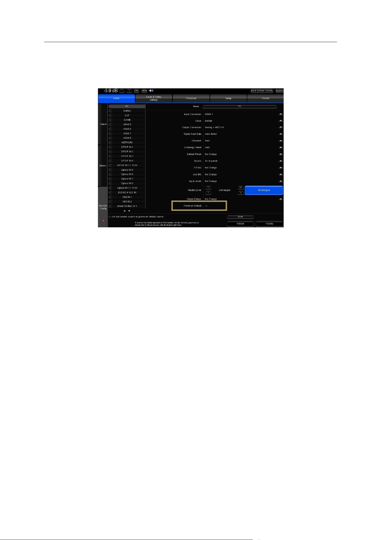
63
5.3 DEFAULT SOURCE CONFIGURATION
When using the factory preset, the SDP-75 uses the last loaded source as power-on default source. This can be
modified in the Home/Sources Config page of the Advanced Settings Interface:
Default#Source#
Select the vertical tab of the source you want to use as default source. Tick the Power-on Default checkbox. Press the
Save button to apply the new parameter of the source.
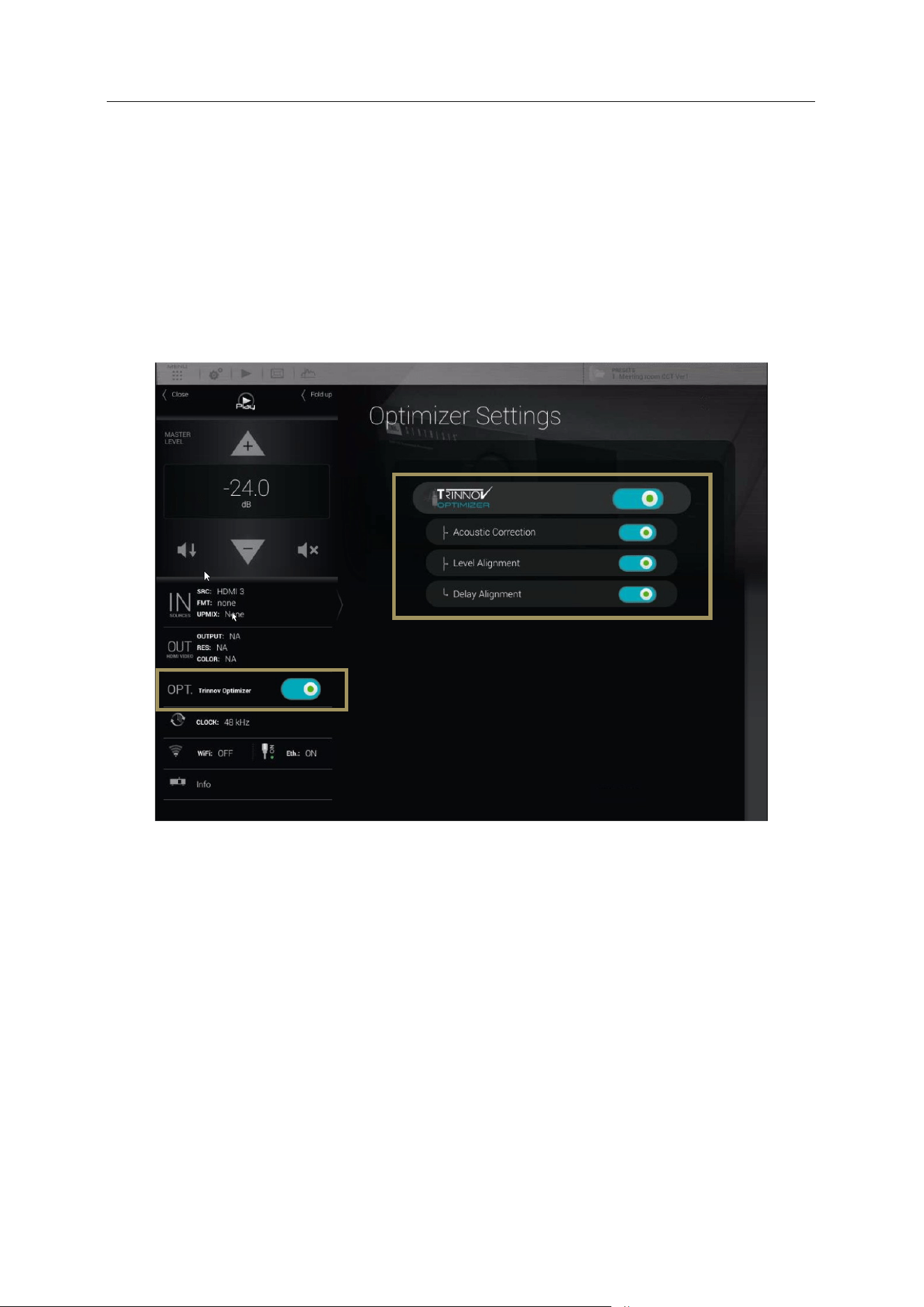
64
5.4 LEVEL AND DELAY ALIGNMENT OPTIONS
The SDP-75’s optimization of the system can be switched on/off via the Main interface.
To switch on/off the alignment options, click on the “OPT. Trinnov Optimizer" menu item of the lateral menu. The
following alignment options are available in this page:
• To activate/deactivate all of the Optimizer settings:
o The Trinnov Optimizer switch
• To activate/deactivate specific parts of the processing:
o The Acoustic correction switch
o The Level alignment switch
o The Delay alignment switch
Figure#43:#Optimizer#Settings#page#
• Trinnov Optimizer ON/OFF: switch on/off the automatic correction of the in-room response: The acoustic correction,
and the automatic delay and level alignment. When the Optimizer is off, only the manual settings related to the audio
processor are applied:
o Routing, as defined in Speaker Configuration Table in the 3D View page of the Main interface;
o The Active Xovers frequencies and filters;
o Levels, as defined in the Processor pages of the Advanced interface;
o Graphic EQs, as defined in the Processor pages of the Advanced interface;
o Bass Management, as defined in the Fine Tuning page of the Main interface.
• Acoustic Correction ON/OFF: when turned off, both the automatic equalization (defined by the target curve) and the
FIR EQs (defined in the Processor/Outputs page of the Advanced interface) are bypassed;
• Level Alignment ON/OFF: disable the automatic alignment of speaker levels, meaning that no automatic gain
changes will be applied to the outputs;
• Delay Alignment ON/OFF: disable the automatic alignment of speaker distances, meaning that no automatic delays
will be applied to the outputs.
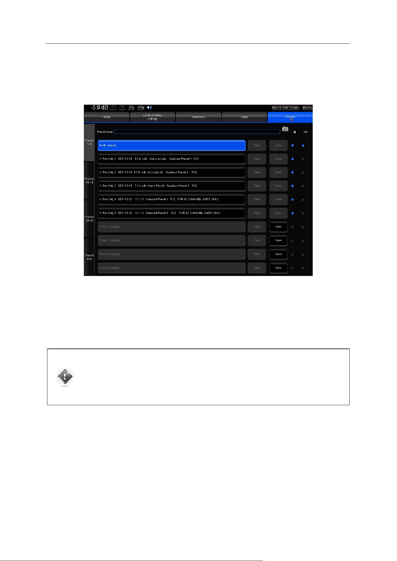
65
5.5 NAMING, SAVING AND LOADING PRESETS
The SDP-75 can store up to 29 memory presets.
Presets can be managed in the Presets menu of the Advanced Settings Interface
Figure#44:#Presets#1-9#page#
The most important parameters included in a preset are:
• The Optimizer adjustments, including
acoustic correction, level and delay
• The settings of the manual filters
• The output configuration and routing
IMPORTANT NOTES:
• Except for sources settings, consider that everything is saved in a preset.
• Any parameter change will be lost if not saved in a preset.
• Please manipulate presets with care since overwriting a preset does not require confirmation.
The Presets page consists of four vertical tabs:
• Presets 1-9: includes the Built-in preset and presets 1 to 9
• Presets 10-19: includes presets 10 to 19
• Presets 20-29: includes presets 20 to 29
• Preset Info: shows the current preset information
Each Preset tab consist of the following items:
• The Preset name field: used to enter or modify a preset's name.
• 10 memory slots including from left to right:
o The Preset name/number, greyed out when the slot is empty, highlighted in blue when the preset is
selected.
o A Clear button to clear the memory slot. This function irreversibly deletes the preset's parameters.
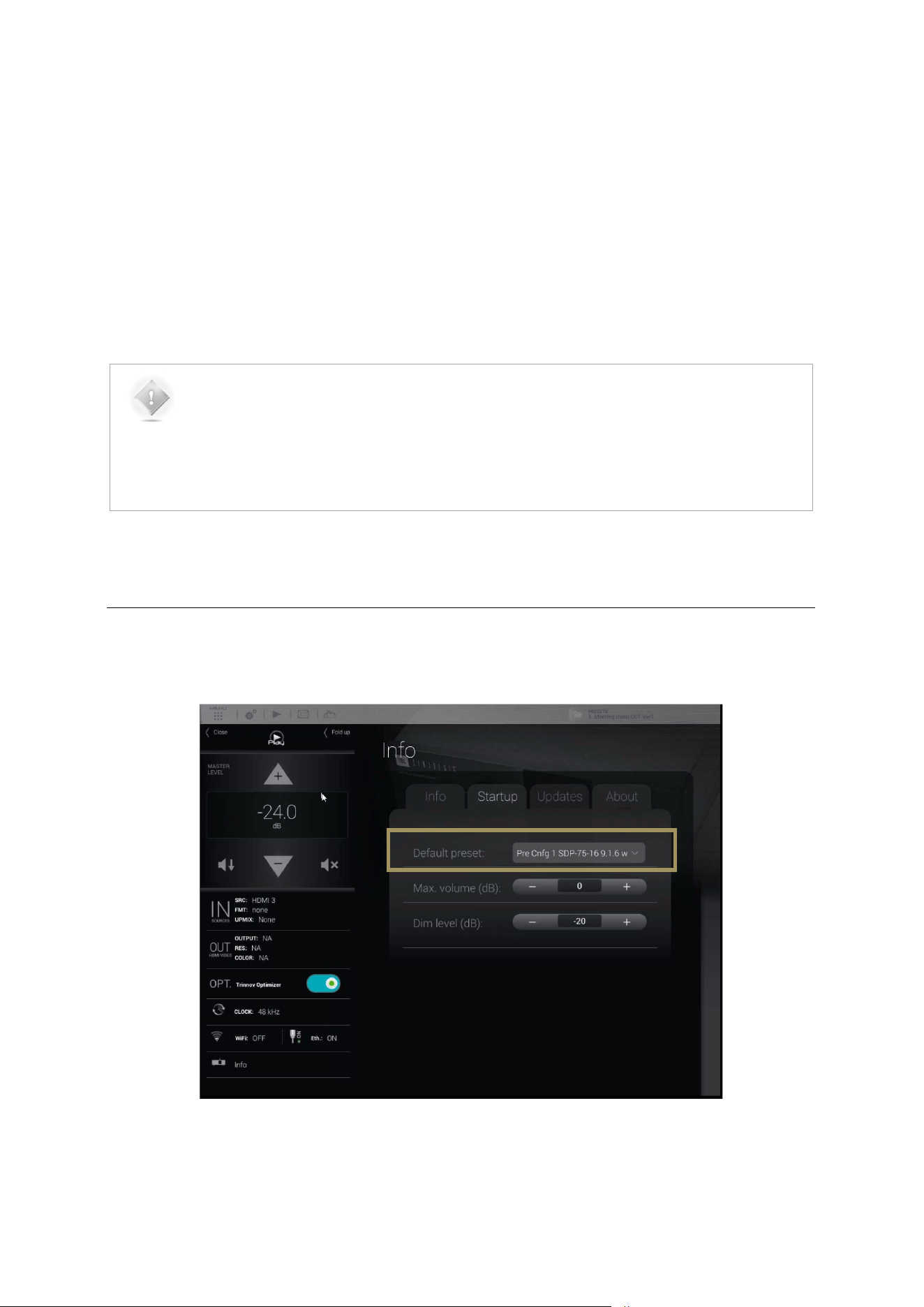
66
o A Save button to save current parameters as a preset in the memory slot.
o A Lock checkbox to protect the preset: disables the Clear & Save buttons.
o A Def (for default) checkbox to automatically load the preset as default after start-up.
As an example, the recommended procedure to duplicate a preset and copy it in a different memory slot would be to:
1. Reload the preset to recall the exact configuration you want to duplicate.
2. Use the Save button of an empty preset to copy it.
NOTES:
• The Built-in preset is locked and cannot be overwritten.
• A specific preset can be linked to each source. Please refer to the Basic Settings chapter.
• Presets can be backed-up and restored to/from a USB key. Please refer to the Basic Settings
chapter.
5.6 DEFAULT PRESET
The default preset can be selected in the Startup option page of the product information menu:
Figure#45:#the#Info/Startu p #p a g e,#d e f a u lt #p re s e t#
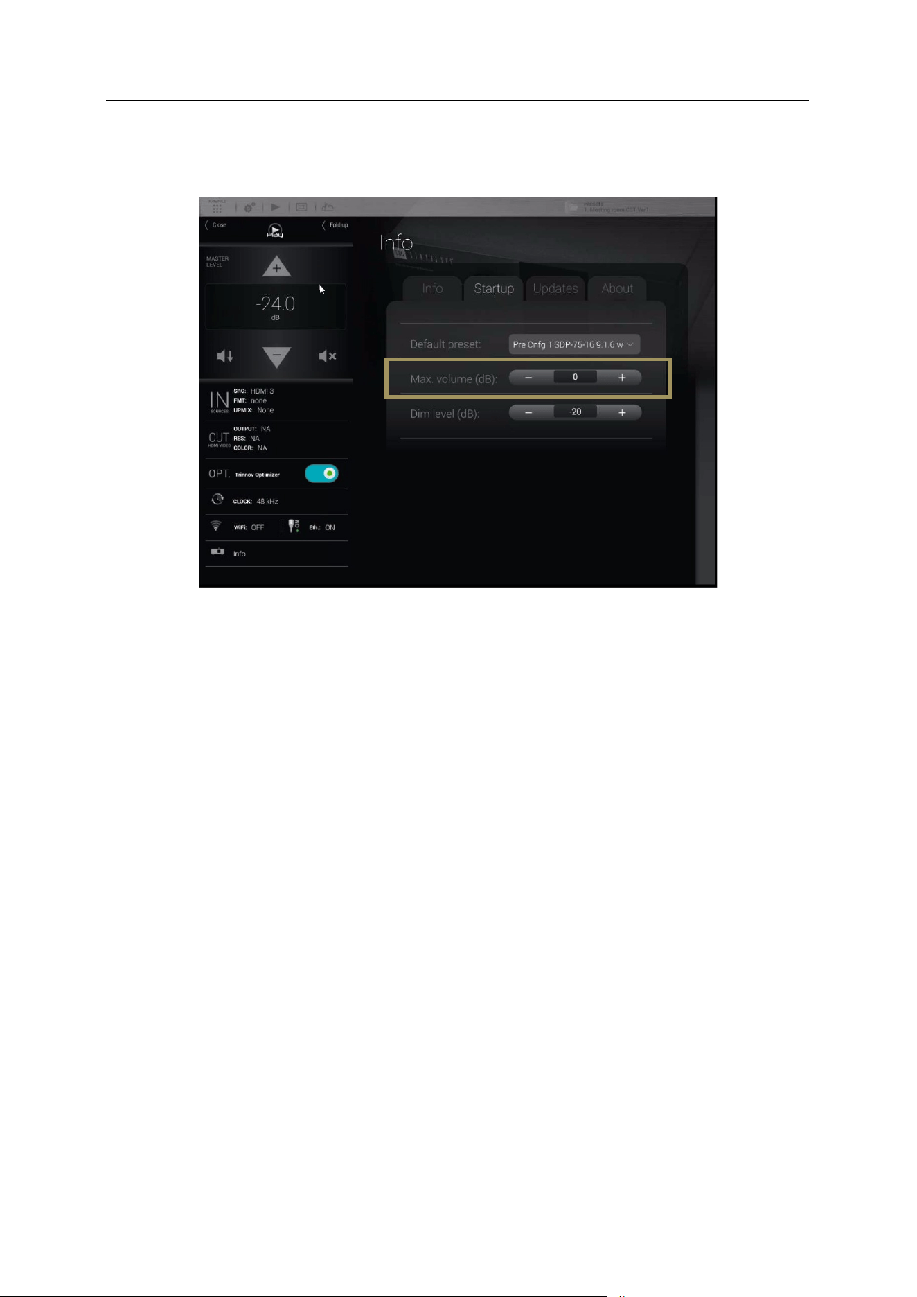
67
5.7 SET A MAXIMUM VOLUME
The Maximum volume can be selected in the Startup option tab of the product information menu:
Figure#46:#the#Info/Startu p #p a g e,#maximum#volume#
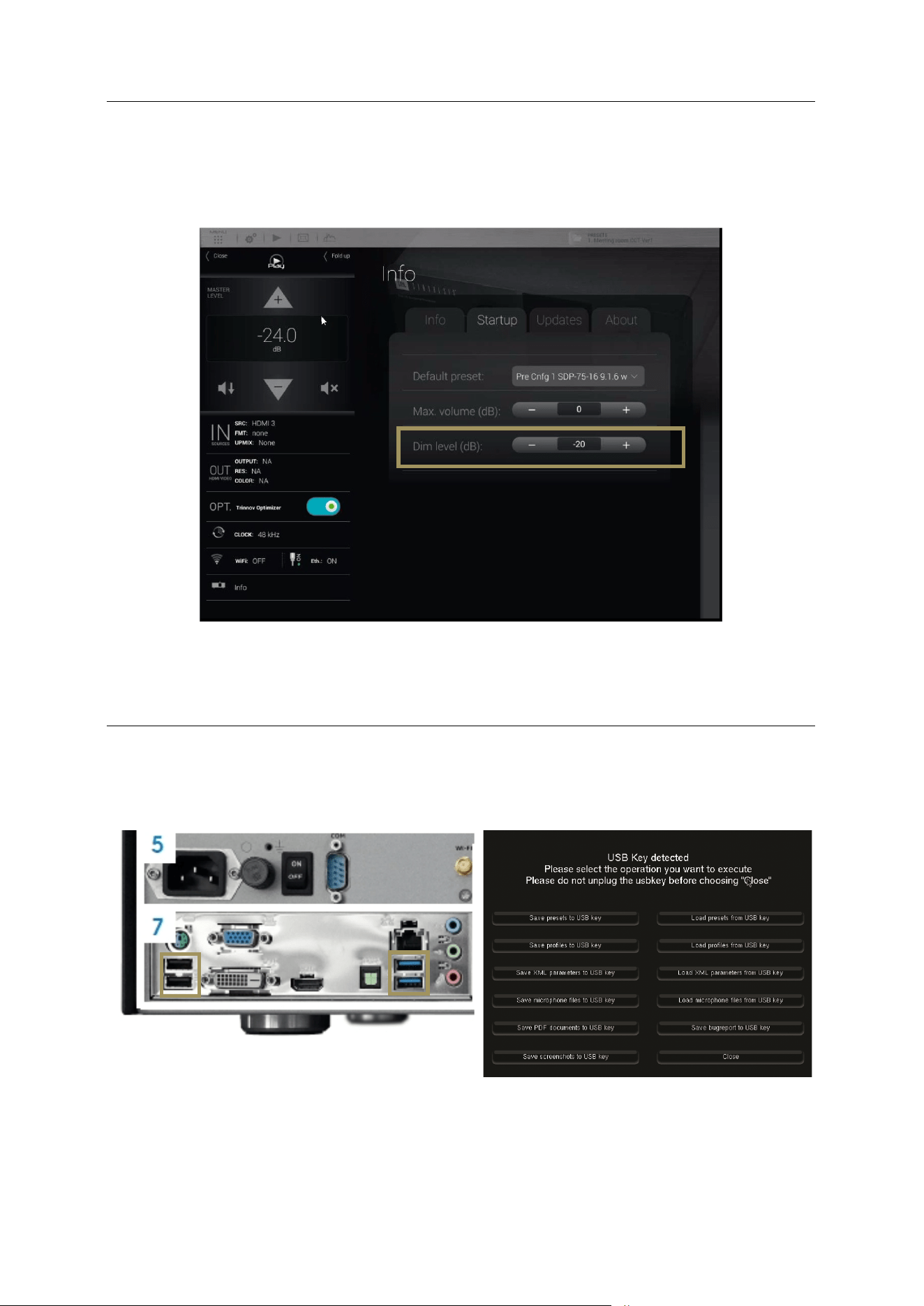
68
5.8 SET THE DIM LEVEL
By default, the Dim is applying a -20dB on the master volume. The value can be change in the Info menu of the main
page, Setup tab. Here, the parameter Dim level (dB) will define the amount of Dim to apply on the master volume when
the Dim is engaged.
Figure#47:#the#Info/Startu p #p a g e,#Dim#level#
Backup/Restore of presets
5.9 BACKUP/RESTORE OF PRESETS
SDP-75#Rear#panel#-#USB#Ports#
USB#Pop-up#menu#
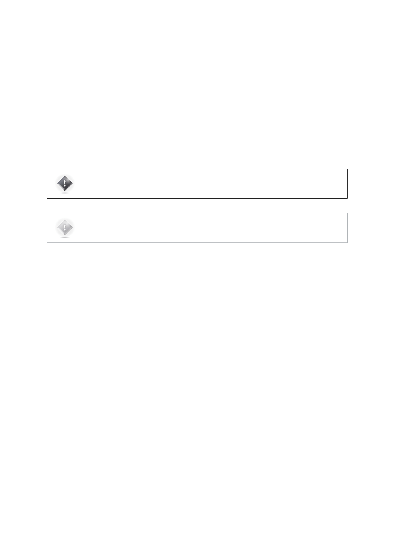
69
Several parameters can be saved, archived and restored using a USB key:
1. Insert a USB key in one of the USB Port located on the rear panel of the SDP-75.
2. As the USB Pop-up menu displays, select the operation you want to execute:
o Save or Load presets to/from the USB Key
o Save or Load profiles (sources configurations) to/from the USB Key
o Save or Load microphone compensation files to/from the USB Key
o Save a Bug report to the USB Key: when an expected error occurs, the system is halted to prevent
damage to your system and a bug report is generated. After the restart of the SDP-75, you can save
that bug report on the USB Key and send it to JBL Synthesis Support at [email protected].
o Save Screenshots to the USB Key: you can take screenshots of the SDP-75’s Graphical User Interface
by pressing the “print screen” key of a keyboard connected to the SDP-75.
IMPORTANT NOTE: to ensure the data integrity of your USB Key, please press the Close button and wait
until the USB Pop-up menu has disappeared to remove it.
NOTE: be careful when reloading presets from a USB Key: preset are identified by their memory slot.
Therefore, a preset initially saved as preset number 5 would overwrite the preset number 5 stored on
the SDP-75 without warning.

70
6 OVERVIEW OF THE SETUP
PROCEDURE
The following summary provides an overview of the overall setup procedure that must be followed
for a smooth and successful setup of the SDP-75 in a home theatre system.
A) Get ready for the installation
First of all, before you start, you must carefully read two key chapters that provide important information about
the SDP-75 tools and settings, as well as very important tips and recommendations to perform the acoustical
measurements:
1. Read the whole chapter about the SDP-75 Essential Tools and Settings;
2. Read the whole chapter Getting Ready for Calibration to get mandatory information on calibration
procedure.
B) Perform the installation
Once you’ve learned the tools & tips, you are ready to follow the setup procedure:
Please note: it is critically important to follow the steps in the specified order, otherwise the system will not
perform properly:
1. Specify the speaker layout in the SDP-75 graphic user interface: choose and configure the speaker layout.
Send pink noise to verify that the routing of the speakers is correct.
2. Optional: if one or more speakers require multi-amplification: configure, calibrate and verify the SDP-75’s
intelligent active crossovers.
3. Fine-tune the speaker system in the room:
a. Measure all the speakers with the SDP-75’s automated measurement and optimization tools;
b. Optional: if required, Setup Bass Management for multiple speakers;
4. Last but not least: verify the sound of the speaker system.
All these steps are explained in detail in the following chapters.
NOTE: the setup procedure of the SDP-75 can be performed:
• With a VNC Client connected to the SDP-75 through the network,
• With a display, a mouse and a keyboard directly connected to the SDP-75’s back panel.
However, the setup procedure cannot be performed with a web browser connected to the SDP-75’s web-based interface.
Further details about the web interface are provided in the Introduction chapter at the beginning of this document.
For a detailed step-by-step explanation of how to connect with a VNC Client, please see corresponding pages in the
Network Setup chapter. For additional details about connecting a display, a mouse and a keyboard, please refer to the
Introduction chapter at the beginning of this document.
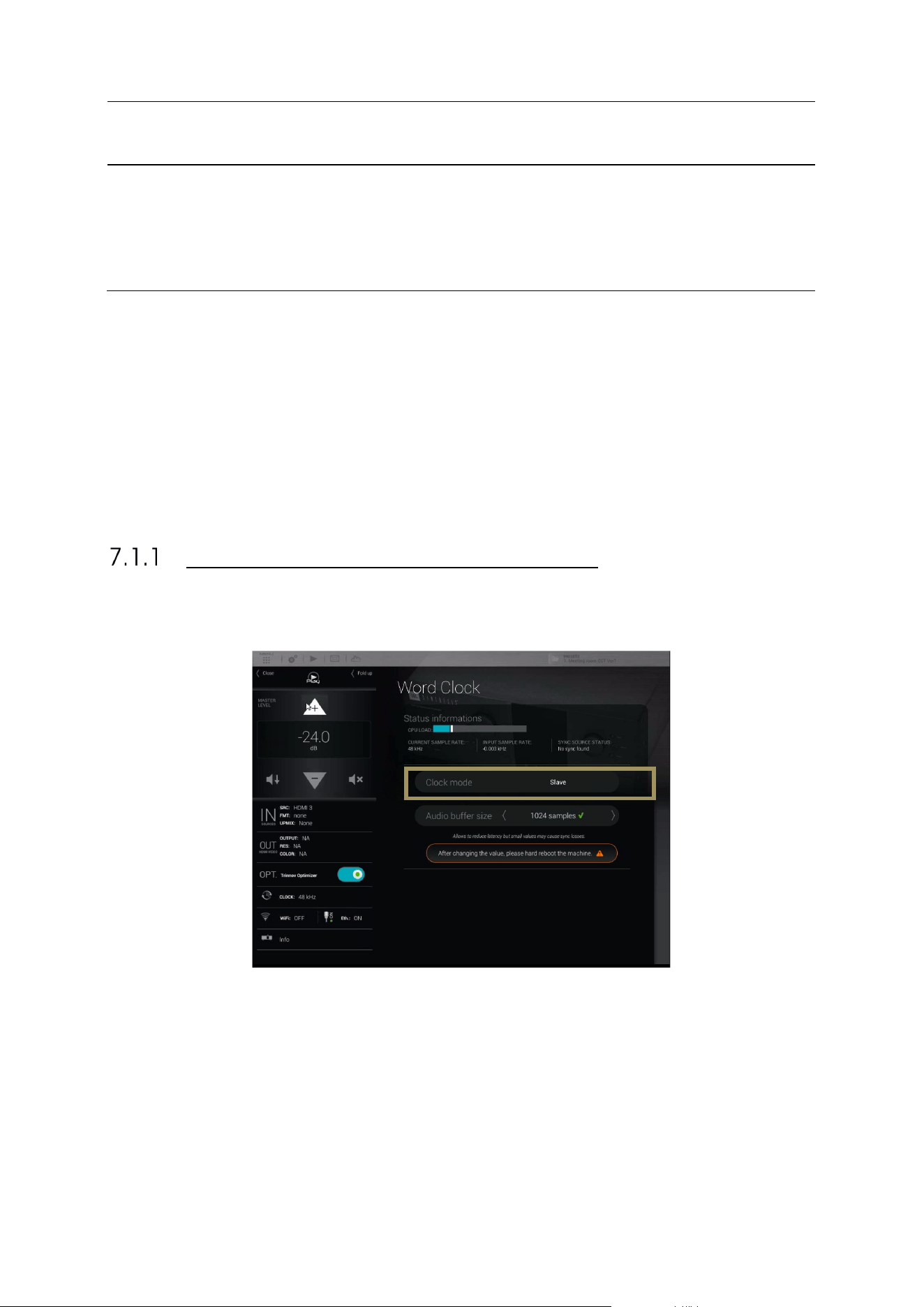
71
7 ESSENTIAL TOOLS AND SETTINGS
This chapter provides important information you need to know before you proceed with the setup
procedure and the measurement process.
7.1 AUDIO CLOCK SETTINGS
At various times during the setup procedure, you may need to check the status of the audio clock or to manually change
its settings
By default, the audio clock automatically switches to Secondary mode when you select a digital source, or to primary mode
when you select an analog source. However, during the calibration procedure, you will select the microphone inputs, and
you will later switch to an HDMI source to verify the sound of the system. At some point, the SDP-75
may be set to Secondary
mode but may not be receiving any clock information if the digital source is not connected. In this situation, the system
is not able to produce sound, like pink noise or sine waves. If this happens to you, please set the clock to primary mode,
or simply switch to an analog input.
AUDIO CLOCK STATUS INFORMATION
The Word Clock page in the main window provides information about the status of the audio clock:
Figure#48:#Audio#clock#s ta tu s#in f o rmation#
The information about the status of the audio clock includes:
• the clock mode: secondary or primary. This setting can be changed in the Setup/Clock page of the Advanced
Settings interface (see below).
• the current sample rate: the sample rate currently used by the SDP-75. If the clock is in secondary
mode it corresponds to the input sample rate. If the clock is in primary mode, it corresponds to the sample rate
selected in the Setup/Clock page of the Advanced Settings interface.
• the input sample rate: the detected sample rate of the currently selected input.
• the current sync source: may be internal, if the clock mode is set to primary, or related to the currently selected
source.
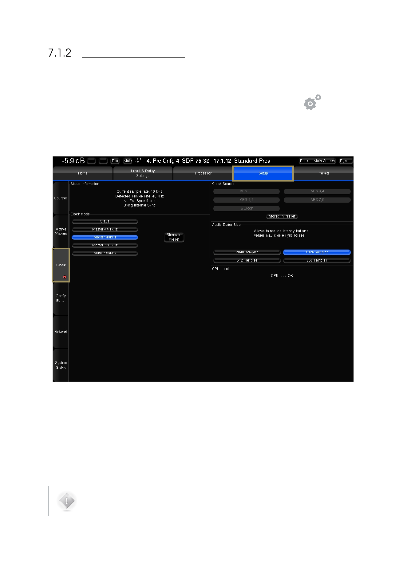
72
AUDIO CLOCK SETUP
Audio clock setup is available through the Advanced Settings interface of the SDP-75.
To access the clock settings page:
1. Click on the Gears button in the top menu to open the Advanced Settings user interface.
2. Go to the Setup/Clock tab of the graphical user interface.
The Clock page of the Setup tab includes all the clock settings:
Figure#49:#Clock#settings#p a ge #in #the#Advanc e d #S et tin g s#
The Setup/Clock page includes:
• Status Information: the same information provided in the Clock page of the main user interface.
• Clock Mode: secondary or primary modes.
• Clock Source: one of the digital inputs or the internal Word Clock of the SDP-75.
• Audio Buffer Size: different buffer sizes, used to reduce latency. The buffer can be reduced to 512 samples to
reduce audio latency, but this may cause sync problems. Only recommended for advanced users.
NOTE: Default buffer size is 1024 samples. It is recommended to keep this value to avoid any problems.
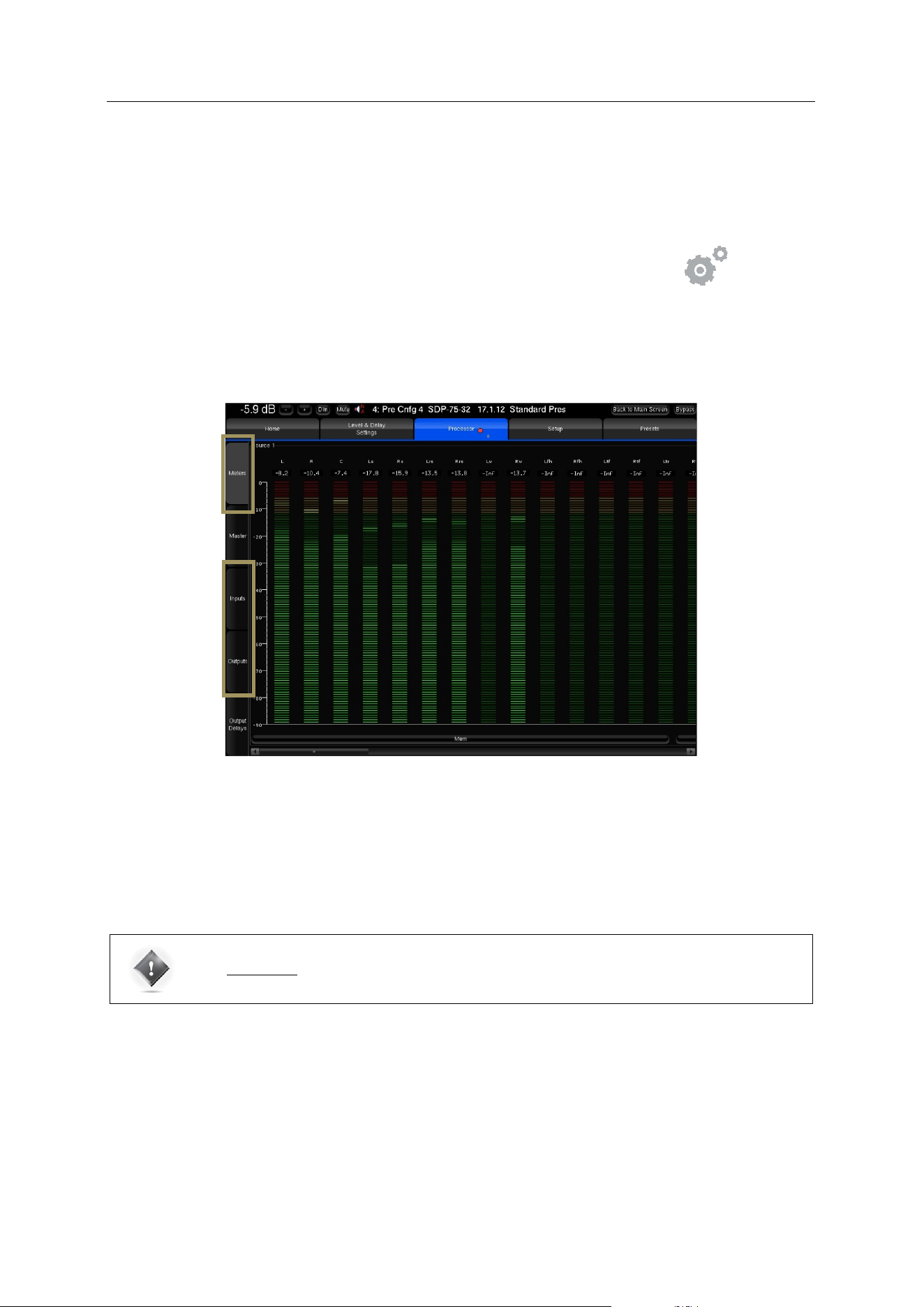
73
7.2 METERING THE INPUTS AND OUTPUTS
The SDP-75 includes an extensive set of audio tools to perform various tests and manual operations during the setup
process.
To access the audio tools:
• Click on the Gears button in the top menu to open the Advanced Settings interface.
• Go to the Processor tab of the graphical user interface.
The main page of the Processor tab displays the input and output meters and a set of lateral tabs:
Input and Output levels can be monitored through the Processor/Meters page. Both the peak levels and the RMS levels
are displayed:
Figure#50:#metering#inpu ts #a n d #o u tp u t s#
You can visualize the peak level of each channel. The highest level registered on each channel can be displayed by
pressing the Mem button. When the level gets close enough to the saturation level, the name of the channel appears
highlighted in red. The Clear button resets the memory and the saturation indicators for every channel of the group.
IMPORTANT NOTE: A digital signal cannot technically exceed 0 dBFS. Therefore, the red tag on top of
each digital input channel only indicates when the maximum level of 0dBFS is reached and does not
necessarily indicate distortion or clipping.
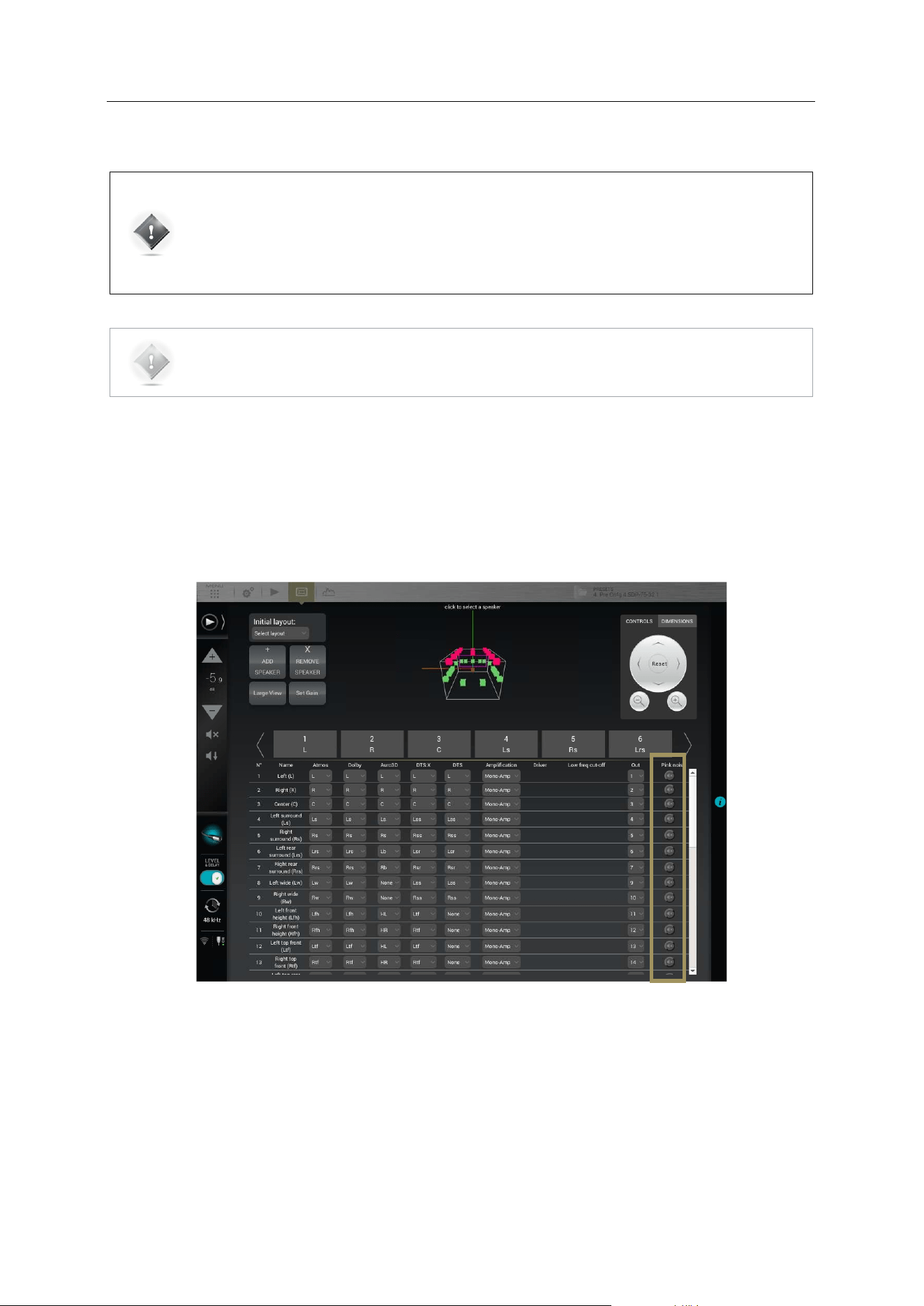
74
7.3 PLAYING PINK NOISE ON THE SPEAKERS
IMPORTANT NOTE: be careful about the output level before playing a test signal.
The Pink Noise generated from Speakers/Room setup tool is following the THX recommendations and
is generated at -30dBFS
The sine wave and pink noise generated from the Processor/Input page are both generated at -20dBFS
RMS.
NOTE: To be able to produce pink noise, the SDP-75 needs to have Word Clock synchronization.
Be careful to use an analog source to be in primary clock, or that your digital device connected to the
SDP-75 and selected
is providing a clock signal.
Pink noise can be played:
• from the Speakers/Room setup tool
• in the Advanced Settings interface, from the Processor/Inputs page
To play a pink noise from the Speakers/Room setup tool, click on the Pink Noise button of the
corresponding output channel:
Figure#51:#playing#Pink#N o ise #from#the#Speakers/Room#setup#tool#
The Processor/Inputs tab provides a complete set of processing options for each input channel. It allows you to send a
1000Hz sine wave or pink noise for every channel.
• To send a 1000Hz sine wave, click on the Sine button.
• To send pink noise, click on the Pink Noise button.
For instance, you can use Pink Noise for setting up your equalization as follows:
• In the Processor/Inputs page, press on the Pink Noise button for the channel you want to equalize,
• Switch to the Processor/Outputs page and open the Preset EQ or User EQ for that same channel,
• Make your EQ adjustments,
• Use the Previous/Next buttons: the pink noise will follow to the same channel.
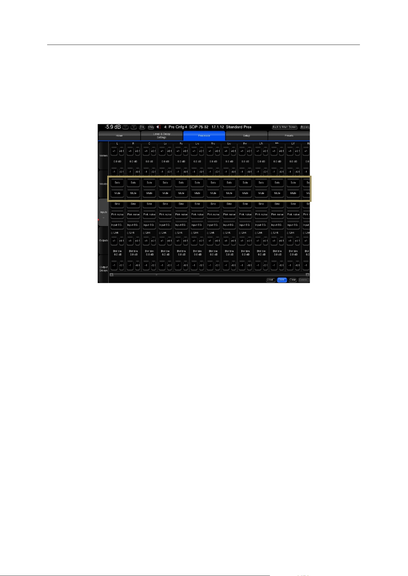
75
7.4 SOLO/MUTE AN INPUT OR AN OUTPUT
The Inputs page and the Outputs page include Mute and Solo buttons that allow you to mute or solo any input or output
channel at any time.
To Mute/Solo an input channel, go to the Inputs tab and click on the Mute/Solo button of the corresponding input
channel:
Figure#52:#Mute#and#Solo#button s#in #t h e#In puts#page#o f#t h e#P rocessor#me n u#
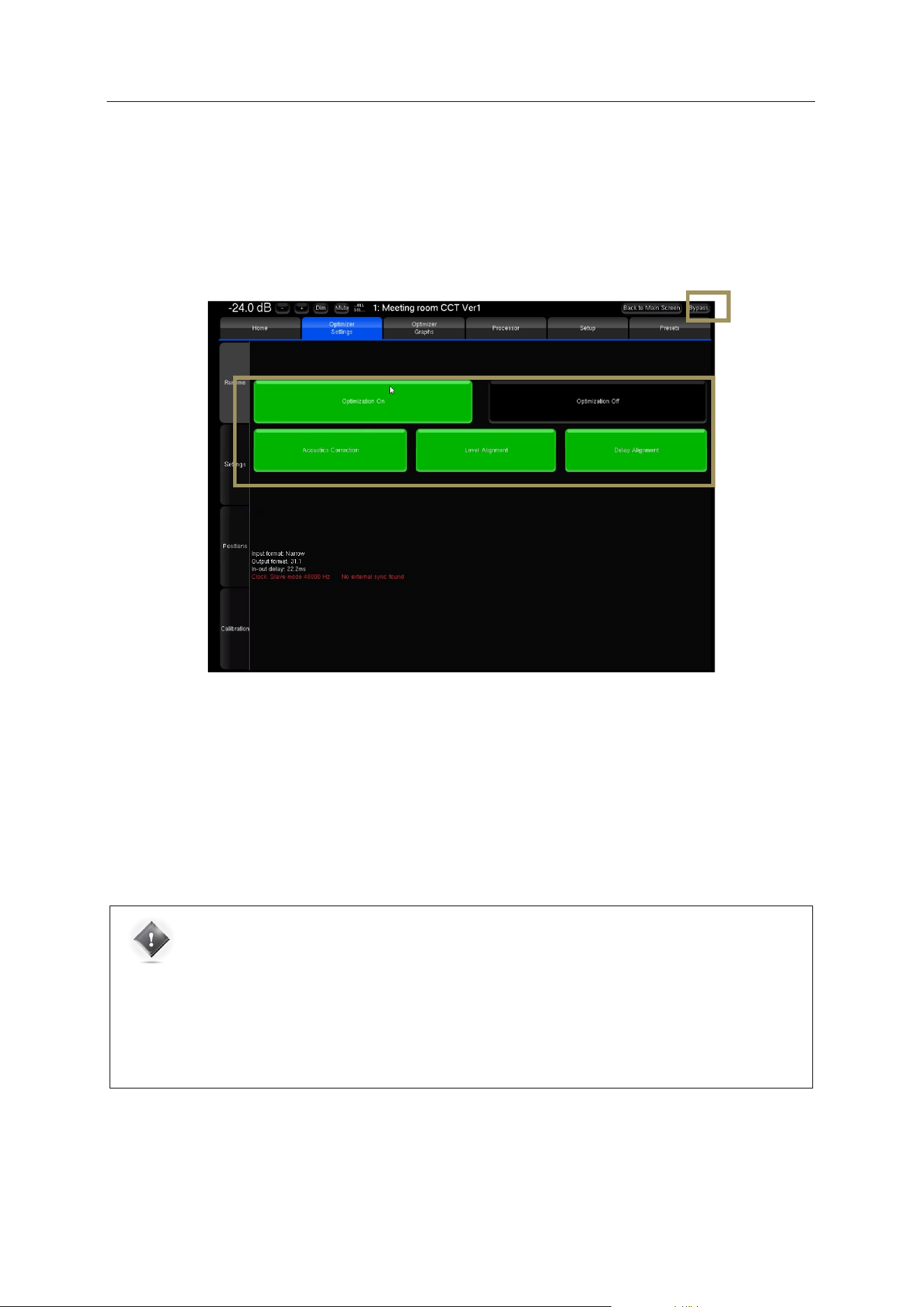
76
7.5 SWITCHING ACOUSTICS CORRECTION
AND LEVEL / DELAY ALIGNMENT ON/OFF
The SDP-75 offers two different ways to compare the sound of your system with or without all Optimization, or selectively
Acoustics Correction, Level Alignment, and Delay Alignment:
• The Bypass button, which is always visible at the top right corner of the Advanced Settings user interface.
• The Optimization On / Optimization Off buttons in the Optimizer Settings/Runtime page.
Figure#53:#switching#opt im iz a tio n #o n / o ff#in #t h e#A d v a n c ed #user#interface #
Optimization On/Off buttons: the buttons in the Optimizer Settings/Runtime page allow the user to selectively
enable/disable the different corrections applied by the Optimizer.
These options are also available in the Main user interface in the Optimizer page.
Bypass button: the bypass button located at the top right corner of the graphical user interface is equivalent to the
Optimization Off button
IMPORTANT NOTE: the Optimization On/Off and Bypass buttons disable the automatic compensation
but manual correction is still applied :
• FIR and Graphic EQs
• Input and output gains
• Outputs delays
• Bass Management
• Active Xovers
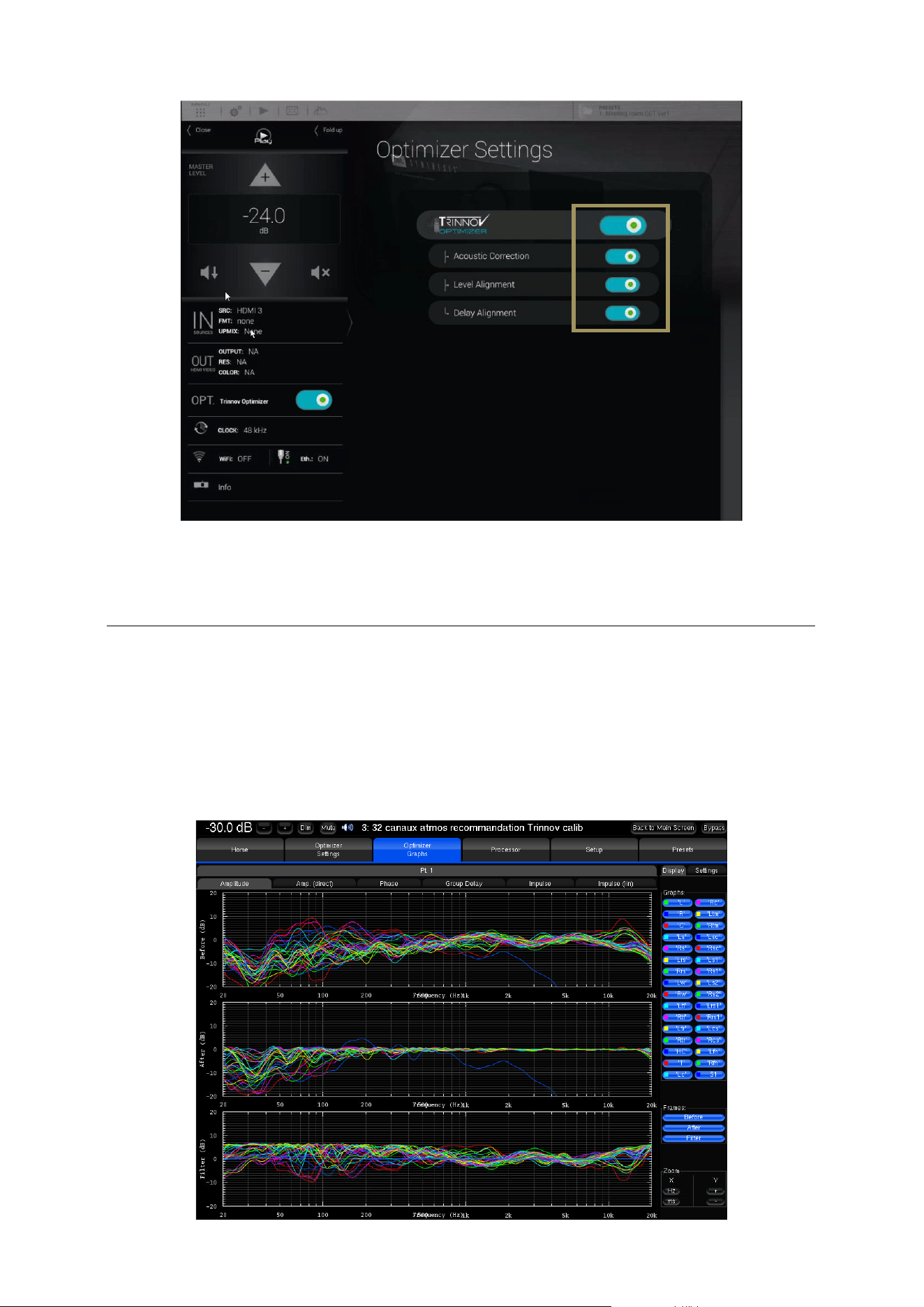
77
Figure#54:#switching#the#Optimization##on/off#in#the#Main#user#interface#
7.6 VIEWING THE ACOUSTICAL GRAPHS
The SDP-75
is a complete and flexible tool for displaying the responses of the speakers before and after the Trinnov
optimization, as well as the correction filters.
The acoustical graphs are available in the Optimizer Graphs page of the Advanced user interface. It is possible to display
the acoustic responses of multiple speakers and analyze the information from various points of view: amplitude, phase,
group delay, impulse response…
Figure#55:#the#acoustical#graphs#page#
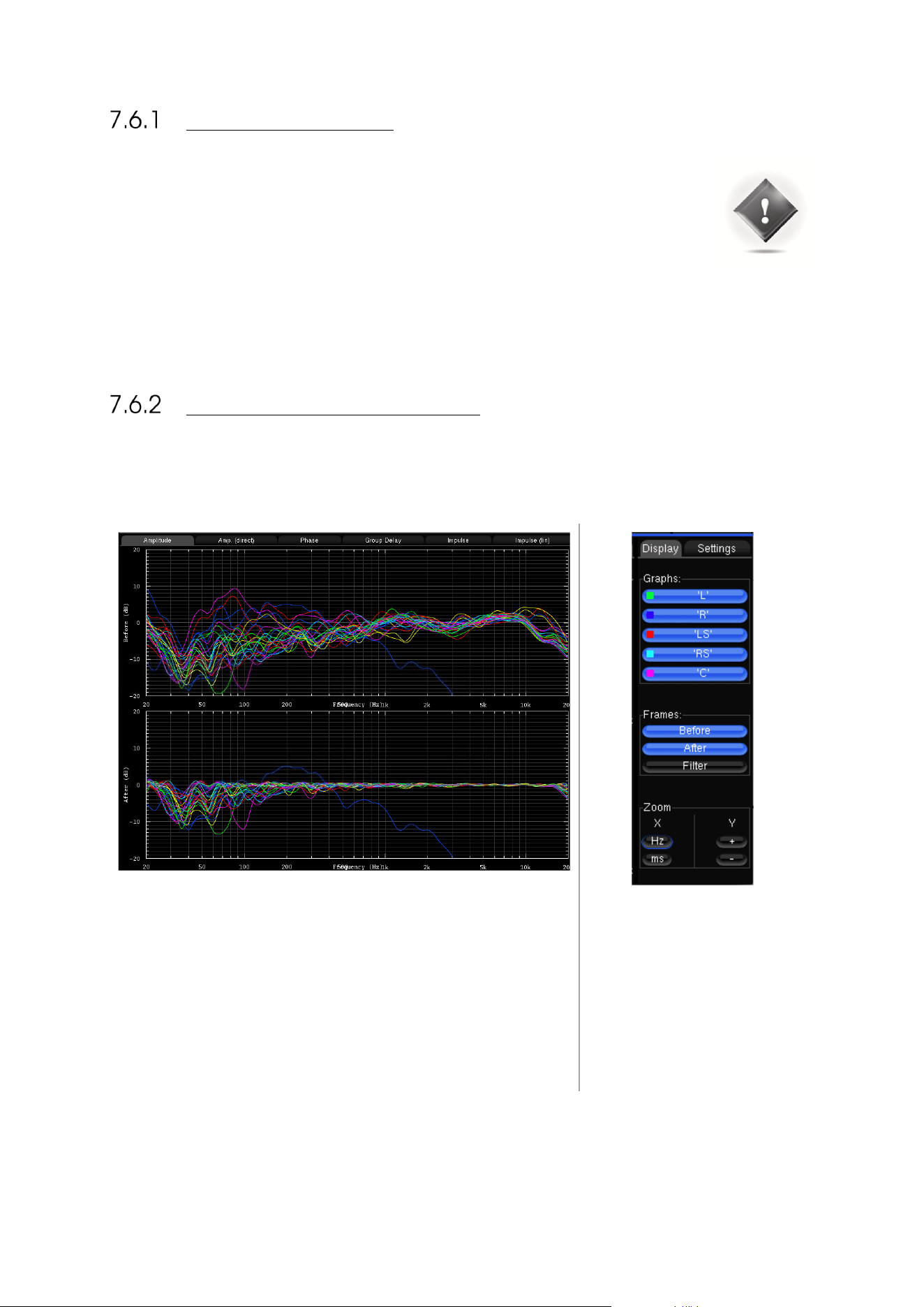
78
IMPORTANT NOTES
It is important to understand the information available on these graphs, as well as the information
that is not available:
• The “after” graphs show the effects of the optimization parameters. These graphs are therefore
based on calculations only, not on measurements. However, measurements with external test
systems have always proved the accuracy of these calculations.
• These graphs only take into account the automatic filters computed according to the Optimizer
Settings page, not the manual adjustments made in the Processor page.
• The display settings will be saved in preset.
GRAPHS DISPLAY OPTIONS
The Optimizer Graphs page consist of a Display area on the left, and a Config area on the right.
The Display area is organized in:
• Tabs & Sub-tabs
• Graphs
• Frames
The Configuration area is organized
in:
• A Display tab
• A Settings tab
Zoom options allows modifying
amplitude, frequency and time
scales according to the type of
representation.
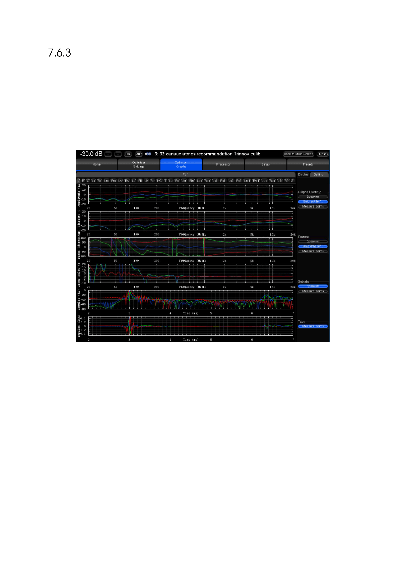
79
CHOOSE DISPLAY OPTIONS ACCORDING TO YOUR
REQUIREMENTS
This feature allows you to visualize on a same screen various type of data, which you can organize as you wish by a few
parameters:
• The Graphs Overlay: type of data you want to overlay on a same graph (or Frame)
• The Frames: type of data displayed vertically on a same tab
• The type of data you want to visualize on each tab and sub-tab.
Figure#56:#Comprehensive#acoustical#graphs#
For each level, you can order the data through various criteria:
• The speaker (L, R, C, Sub, ...)
• The point of measurement: in the case of a multipoint configuration, you can visualize the response measured on
each position, and the effect the optimization has on it
• The type of response: speaker response before optimization, speaker response after optimization, or filter response
• The type of visualization: amplitude, amplitude of the direct front and early reflections only, phase, group delay, or
impulse response.
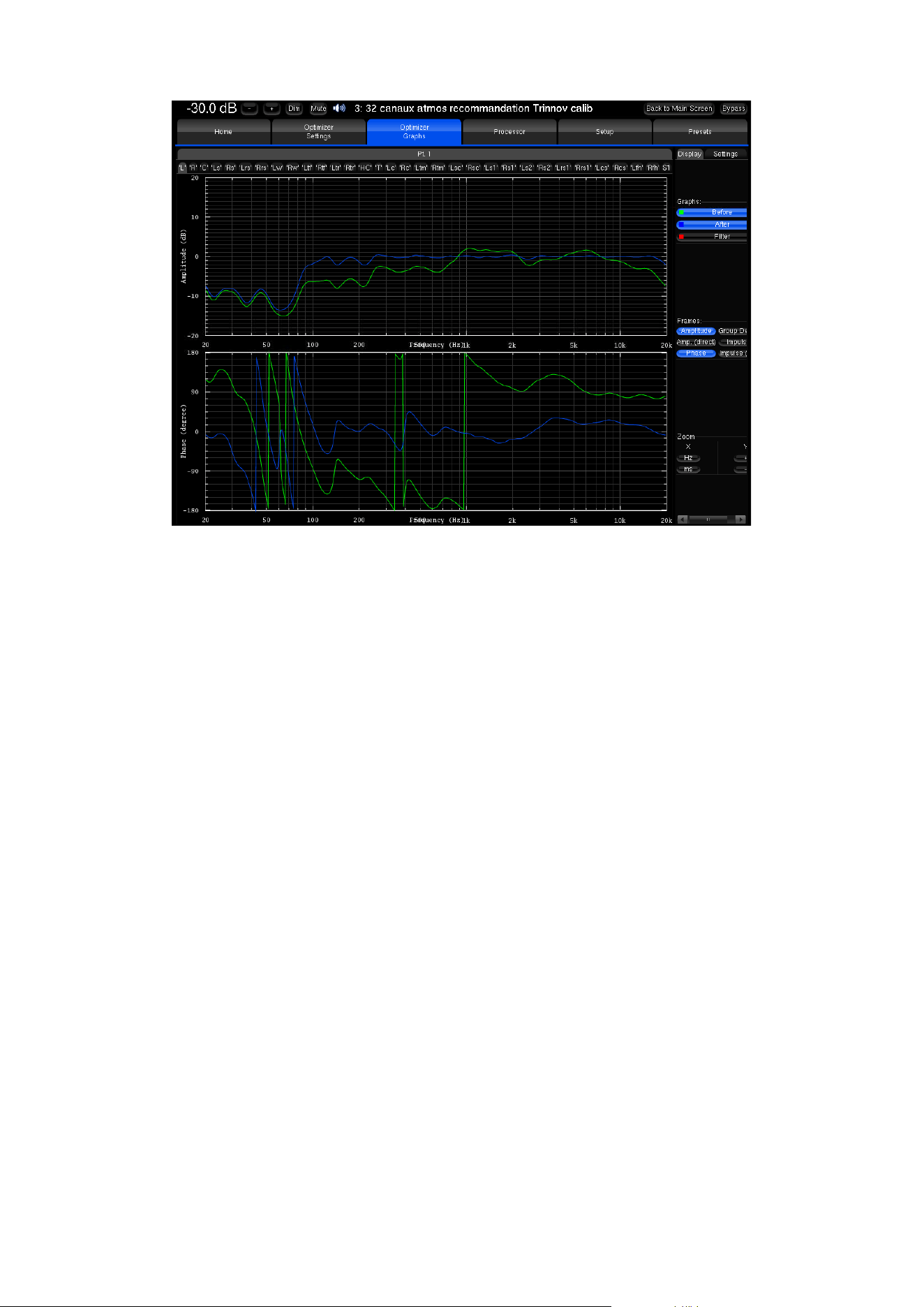
80
Figure#57:#Focusing#on#specific#graphs#

81
8 SPECIFY THE SPEAKER LAYOUT
In this chapter we assume that a specific set of speakers have already been defined and installed in a
room. In order to support multiple surround and 3D formats, we recommend relying on the expertise
of a Certified JBL Synthesis Installer. They can design a speaker configuration that meets your
requirements, and can also recommend optimal speaker placements according to your room’s
dimensions and acoustics.
For additional information about the Dolby, DTS and Auro-3D recommendations, please see the
Appendix of this document and the related documents from Dolby, DTS and Auro.
8.1 OVERVIEW OF THE SPEAKERS SETUP
PROCEDURE
The overall procedure to configure a speaker system is as follows:
• Select an initial speaker layout from one of the available templates;
• If necessary, Add or Remove speakers until your specific layout is defined;
• Configure the settings of each speaker, the channel mapping to Dolby, DTS, Dolby Atmos, DTS:X and Auro-3D
formats, and the output routing;
• Verify the routing of the speakers by playing pink noise on each speaker;
• Set an array of speakers (please see next chapter)
• Save the preset.
Each of these steps is described in detail in the following pages.
8.2 INTRODUCING THE SPEAKER/ROOM SETUP
TOOL
The SDP-75 provides a powerful tool to help you configure the speaker set of your home theatre system. The
Speaker/Room setup tool provides the following features:
• a 3D model of your room that you can rotate and zoom in/out;
• a display of the 3D speaker positions in the room;
• a comprehensive set of surround and 3D speaker layouts so you do not need to start your speaker configuration
from scratch;
• add or remove speakers (satellites and subwoofers);
• detailed configuration of each speaker, the channel mapping to Dolby, DTS, Dolby Atmos, DTS:X and Auro-3D
formats, and the output routing;
• An easy way to set up speakers arrays;
• a pink noise button to easily verify the routing of the speakers.
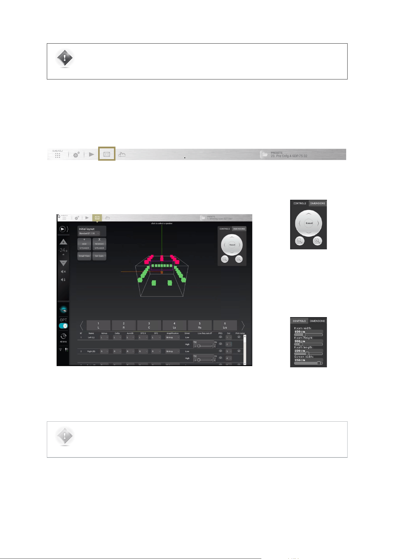
82
IMPORTANT NOTE: it is important to understand that, because the SDP-75’s automated process
measures all the speakers (including the subwoofers) during each measurement. You must create in
the SDP-75’s user interface a speaker configuration that includes all the speakers of your installation
(including the subwoofers).
The Speaker Configuration page can be accessed through the Top Menu of the SDP-75’s graphic
user interface, highlighted below.
#
Figure#58:#The#Speaker/Room#setup#tool#
The Controls box located in the
top right corner of the window
allows you to navigate through
the 3D view. You can rotate the
view, zoom in and zoom out.
The Dimensions tab allows you
set your room dimensions and
screen size.
NOTE: The room visualization is simply a representation showing the theoretical speaker placement of
the selected layout. It is not taken into account for the acoustic optimization and does not affect the
sonic performance of the system. The position of a speaker is not critical but its label will determine
which decoded channel it will reproduce.
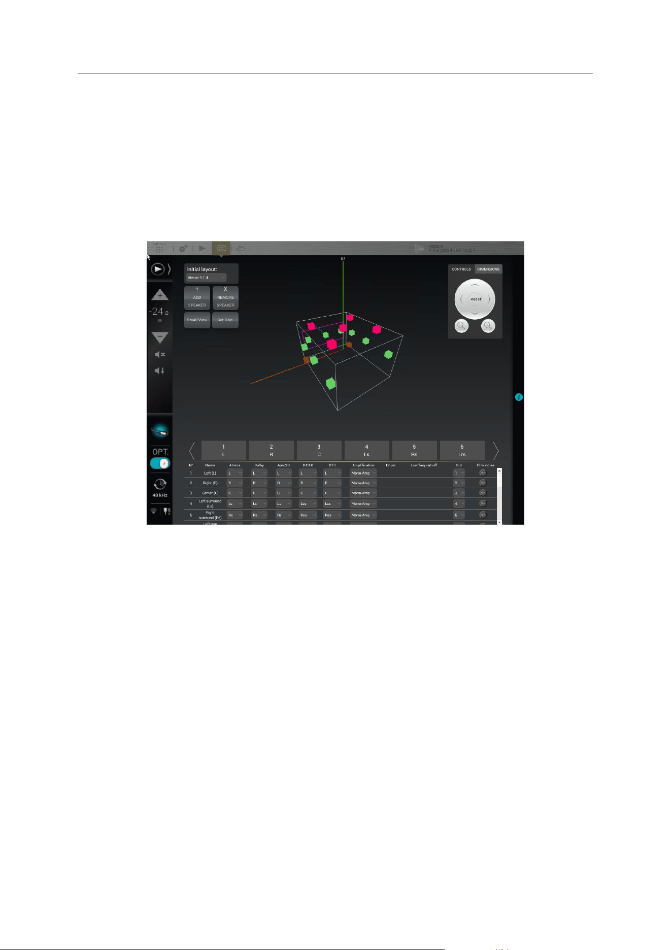
83
8.3 AN EXAMPLE OF A SPECIFIC SPEAKER
LAYOUT
The SDP-75
is designed to support any speaker layout. This includes standard speaker layouts such as those specified
by Dolby, DTS and Auro-3D, but also hybrid speaker layouts based on two or more speaker placement recommendations.
This allows your installation to support the different surround and 3D formats currently available in DVD, Blu-ray, UHD
Discs, streaming media, and file-based media.
Below is an example of a specific speaker layout designed to support multiple formats:
Figure#59:#Example#of#a#specific#configuration#with#16#speakers#
This configuration of 16 speakers includes:
• initial layout (7 full-range speakers + 1 subwoofer)
• 6 additional speakers based on the Dolby Atmos format:
• 2 additional Lw & Rw speakers (Left wide & Right wide)
• 4 additional height speakers: Ltf & Rtf (Left & Right top front) and Ltr & Rtr (Left & Right top rear)
• additional ceiling speaker for the Auro-3D Top channel (“Voice of God”).
• 1 extra subwoofer.
The following pages describe how to setup such a configuration.
84
8.4 AVAILABLE INITIAL LAYOUTS
The following layout templates are available to start your setup process with an initial layout as similar as possible to
your specific configuration.
NOTE: For detailed information about speaker recommendations, please refer to the appendix of this
document and to the related Dolby, DTS and Auro-3D recommendations.
STEREO AND SURROUND LAYOUTS
DOLBY ATMOS LAYOUTS
• Stereo 2.0 (L/R)
• 5.1 (L/R/C/LFE/Ls/Rs)
• 7.1 (L/R/C/LFE/Ls/Rs/Lrs/Rrs)
• Dolby Atmos - 5.1.2 (5.1 + Ltm/Rtm)
• Dolby Atmos - 5.1.4 (5.1 + Ltf/Rtf + Ltr/Rtr)
• Dolby Atmos - 7.1.2 (7.1 + Ltm/Rtm)
• Dolby Atmos - 7.1.4 (7.1 + Ltf/Rtf + Ltr/Rtr)
• Dolby Atmos - 9.1.2 (7.1 + Lw/Rw + Ltm/Trm)
• Dolby Atmos - 9.1.4 (7.1 + Lw/Rw + Ltf/Rtf +
Ltr/Rtr)
AURO-3D LAYOUTS
DTS:X LAYOUTS
• Auro-3D - 9.1 (5.1 + HL/HR + HLs/HRs)
• Auro-3D - 10.1 (5.1 + HL/HR + HLs/HRs + T)
• Auro-3D - 11.1 (5.1 + HL/HR + HC + HLs/HRs + T)
• Auro-3D - 11.1 (7+4) (7.1 + HL/HR + HLs/HRs)
• Auro-3D - 13.1 (7.1 + HL/HR + HC + HLs/HRs + T)
• DTS:X - 5.1.2 (5.1 + Lh/Rh)
• DTS:X - 5.1.4 (5.1 + Lh/Rh + Lhr/Rhr)
• DTS:X - 7.1.2 (7.1 + Lh/Rh)
• DTS:X - 7.1.4 Heights (7.1 + Lh/Rh + Lhr/Rhr)
• DTS:X - 7.1.4 Tops (7.1 + Ltf/Rtf + Ltr/Rtr)
STANDARD LAYOUT
In addition to the Dolby, DTS and Auro3D templates, the SDP-75 includes a set of standard layouts. These
layouts are based on a 7.1 surround layout with additional speakers to support multiple surround and 3D
formats such as Dolby Atmos, DTS:X and Auro-3D.
Note that this layout can be modified to support the largest Dolby Atmos configuration.
• The 16 speaker layout : Standard 9.1.6 (7.1 + Lw/Rw + Ltf/Rtf + Ltr/Rtr + Hc + T)
• 8 speakers (7 full-range speakers + 1 subwoofer) for the 7.1 surround layout
• 6 speakers based on the Dolby Atmos format:
• 2 additional surround speakers: Lw & Rw (Left wide & Right wide)
• 4 additional height speakers: Ltf & Rtf (Left & Right top front) and Ltr & Rtr (Left & Right top rear)
• 1 additional center height speaker for the Center Top Front channel: HC (Auro-3D ) or Ch (DTS:X)
• 1 additional ceiling speaker for the Top channel: T (Auro-3D ) or Oh (DTS:X).
• The 20 speakers layout : Standard 11.1.8 (7.1 + Lw/Rw + Ltf/Rtf + Ltr/Rtr + Hc + T + Ltm/Rtm + Lc/Rc)
• based on the 9.1.6 layout
• 2 additional Top Middle channels : Ltm/Rtm used by Dolby Atmos and DTS:X formats
• 2 additional speakers behind the screen: Lc/Rc used by Dolby Atmos and DTS:X formats.
• The 32 speakers layout : Standard 21.1.10 (7.1 + Lw/Rw + Ltf/Rtf + Ltr/Rtr + Hc + T + Ltm/Rtm + Lc/Rc
+ Lsc/Rsc + Ls1/Rs1 + Ls2/Rs2 + Lrs1/Rrs1 + Lcs/Rcs)
• based on the 11.1.8 layout
• 2 additional speakers behind the screen : Lsc/Rsc used by the Dolby Atmos format
• 4 additional surround speakers : Ls1/Rs1 and Ls2/Rs2 used by Dolby Atmos and DTS:X formats
• 2 addition rear surround speakers Lrs1/Rrs1 used by the Dolby Atmos format
• 2 additional center surround speakers: Lcs/Rcs used by the Dolby Atmos format.
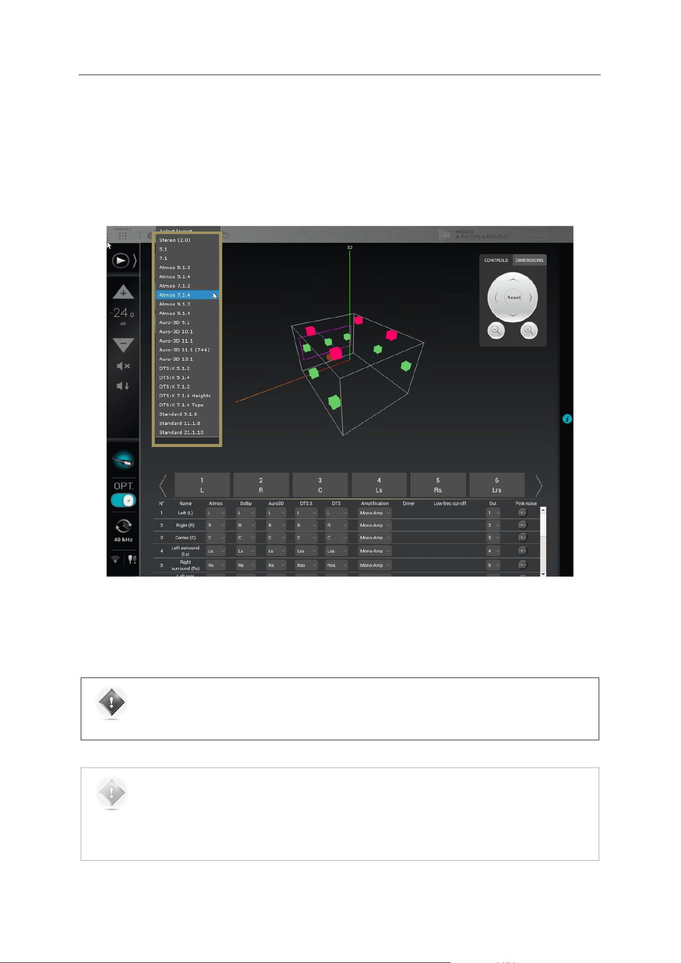
85
8.5 SELECT AN INITIAL SPEAKER LAYOUT
We recommend you to start by selecting the initial layout which is most similar to your specific speaker layout, and then
add/remove speakers. Alternatively, you could also create a speaker configuration from scratch.
To select an initial speaker layout:
• Go to the Speaker/Room setup tool and click on the Initial Layout drop-down list
• Select the layout template which is most similar to your speaker system.
Figure#60:#Selecting#an#initial#speaker#layout#
If your system is not in the list, you can either select a smaller system and add the missing speakers, or select a bigger
system and remove the extra ones.
IMPORTANT NOTE: it is critical to distinguish speakers from channels because one speaker may be
used to reproduce multiple channels, depending on the audio format which is being played. Therefore,
your final speaker configuration on the SDP-75 must include the same number of amplification
channels as in your audio system.
NOTES:
The Speaker/Room setup tool cannot display more speakers than the total number of available outputs
in your SDP-75 configuration. There are 16-channel, 24-channel and 32-channel SDP-75 models. For
example, if you have a 24-channel SDP-75 model, the Speaker/Room setup tool will display up to 24
speakers.
Channel assignment for each format is one of the next steps.
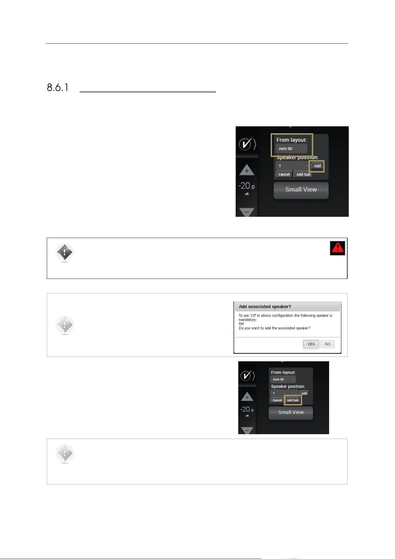
86
8.6 ADDING SPEAKERS
ADDING REGULAR SPEAKERS
If required, the next step is to add speakers to achieve a configuration that fits your system.
To add one or more speakers:
• click on the Add Speaker button
• in the From Layout drop-down list, select the speaker
template from which you want to add one or more speakers:
all the speakers available in the selected speaker layout are
displayed in grey color;
• click on the speaker you want to add: it will be displayed in
yellow color;
• click on the Add button next to the Speaker position drop-
down list;
Repeat this process for each additional speaker you want to add.
#
Figure#61:#Adding#a#speaker#
IMPORTANT NOTE: Some configurations are not allowed by the decoder specifications. In such
case, a red warning will be displayed on the side panel and the relevant speakers will be
highlighted in red.
The side panel gives you some information on the prerequisite conditions for some speakers.
NOTE: If you choose to add a speaker, the SDP-75 will
automatically suggest to add the mandatory associated
speaker(s). This will help you to keep the integrity of the
recommendations of each decoder.
To add a subwoofer:
1. Click on the Add Speaker button;
2. Click on the Add Sub button below the Speaker position drop-
down list.
NOTE: The Add Sub button adds subwoofers regardless of formats. The subwoofer positions displayed
are not significant and will not affect the sound.
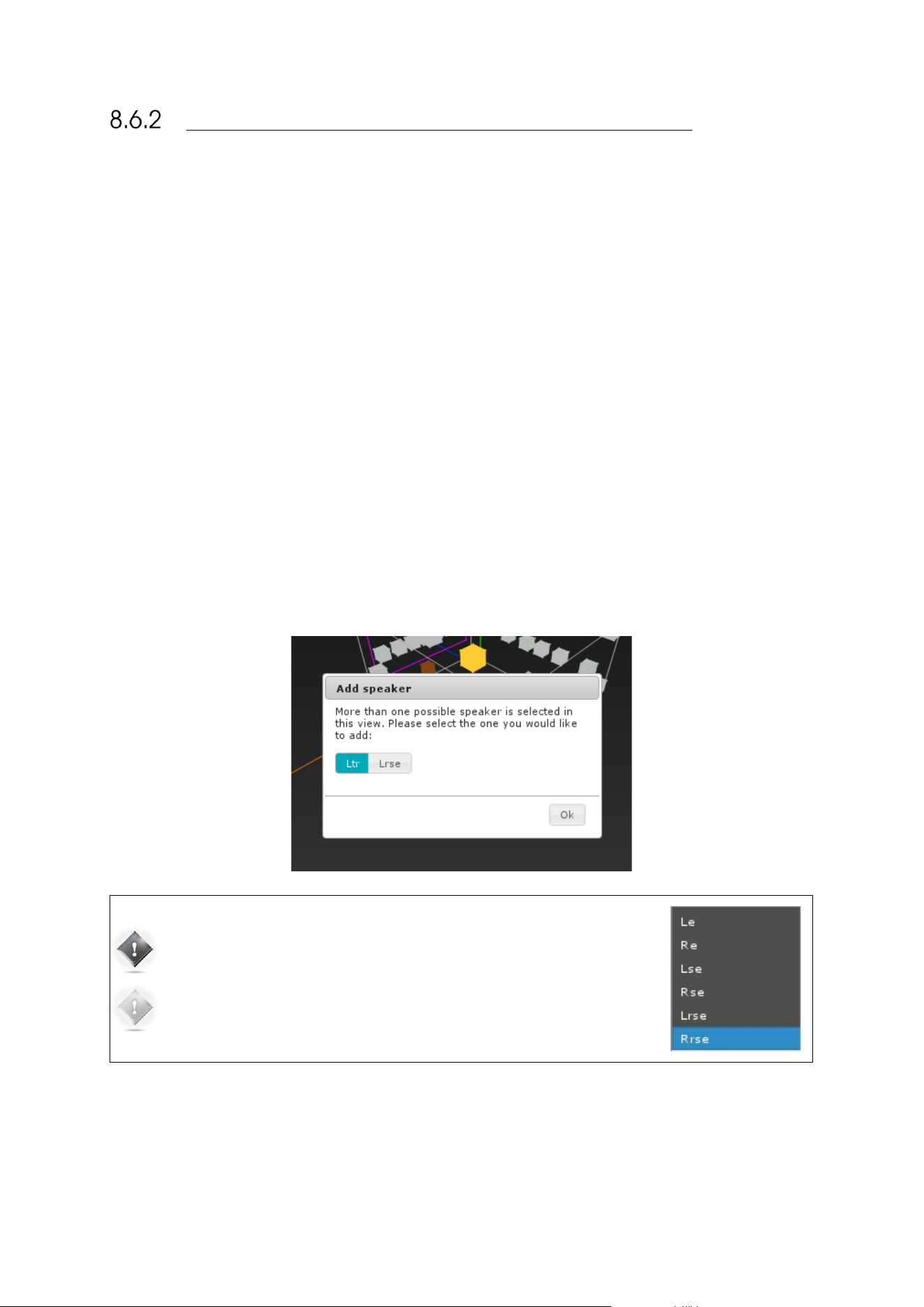
87
ADDING DOLBY ENABLED UPFIRING SPEAKERS
If you configuration has some Dolby-Enabled up-firing speakers, they appears on the 3D view as ceiling speakers as
they are used to reproduce elevation channels. In the drop-down list, those speakers are end in an “e” which stands for
“enabled”.
Here are the available Dolby-Enabled speakers:
• Le: Left up-firing Dolby-Enabled speaker;
• Re: Right up-firing Dolby-Enabled speaker;
• Lse: Left Surround up-firing Dolby-Enabled speaker;
• Rse: Right Surround up-firing Dolby-Enabled speaker;
• Lrse: Left Rear Surround up-firing Dolby-Enabled speaker;
• Rrse: Right Rear Surround up-firing Dolby-Enabled speaker;
To add a Dolby-enable speaker from the drop-down list, please use the normal procedure explained above in the Adding
Regular Speakers sub-chapters.
To add a Dolby-enable speaker from the 3D view, click on one of the Dolby Top Speakers. As explained above, the Dolby
enabled speakers are using the signal from Top speakers to recreate the immersion effect. The speakers concerned are
• Left and Right Top Front (Ltf/Rtf);
• Left and Right Top Middle (Ltm/Rtm);
• Left and Right Top Rear (Ltr/Rtr).
Use the procedure explained in the previous chapter to add a speakers from the 3D view. Select of the speakers listed
above. When clicking on Add, a dialog box will appears asking you to choose between the regular in-ceiling speaker or
the associated Dolby-enabled up-firing speaker. Select the desired one.
IMPORTANT NOTE: The last speakers on the list are up-firing Dolby-Enabled
speakers. Dolby-Enabled speakers have an included filter designed to enhance
the immersion effect.
NOTE: Dolby-Enabled up-firing speakers uses elevation speaker channels. In
cases in which both Dolby-Enabled and celling speakers are used, some
conflicts can occur. It will appear on the side panel.

88
8.7 REMOVING SPEAKERS
To remove one or more speakers (including subwoofers):
• Click on the speaker you want to remove, either in the 3D
representation or in the list: it will be displayed in yellow.
• Click on the Remove speaker button.
#
#
8.8 CONFIGURE THE SETTINGS OF EACH
SPEAKER
Once the complete set of speakers in your system is defined, you can configure the settings of each speaker.
The speaker configuration table located in the lower part of the Speaker/Room setup tool allows you to:
• Manually map the channels of the Dolby, Dolby Atmos, DTS, DTS:X or Auro-3D formats to each speaker;
• Configure the arrays of speakers for Dolby and DTS legacy format (optional) (See Speakers Arrays chapter
bellow);
• Configure the active crossover settings (optional);
• Specify the physical output for each speaker/driver;
• Send pink noise to the assigned physical output in order to verify that the routing of each channel to each
loudspeaker/driver is correct.
The Small View button reduces the 3D view and enlarges the speaker configuration table.
Every speaker can be further configured as follows:
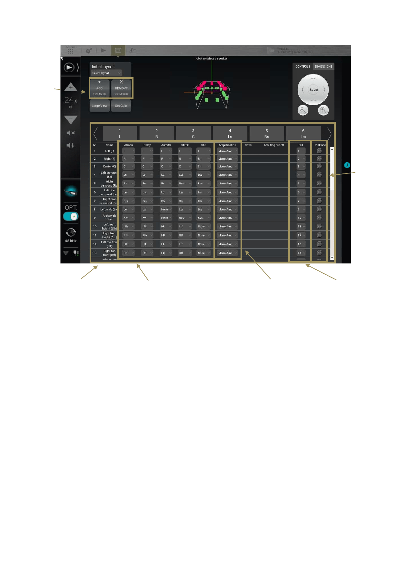
89
Figure#62:#The#speaker#configuration#table#
You can select speakers:
• by clicking on the speaker in the 3D view,
• by clicking on the corresponding channel number/name in the table’s header
• by clicking on one of the lines of the table
The currently selected speaker is displayed in yellow in the 3D view.
The available settings for each speaker are the following:
• Dolby, Dolby Atmos, Auro3D, DTS and DTS:X
channel mapping: see below.
• Amplification: see below.
• Output Channel: specifies the physical output to be
used for the speaker/driver.
• Pink noise: plays a -20dBFS pink noise on the
specified output.
Channel mapping
Speakers name
Multi amplification
Output channel
THX
Pink
noise
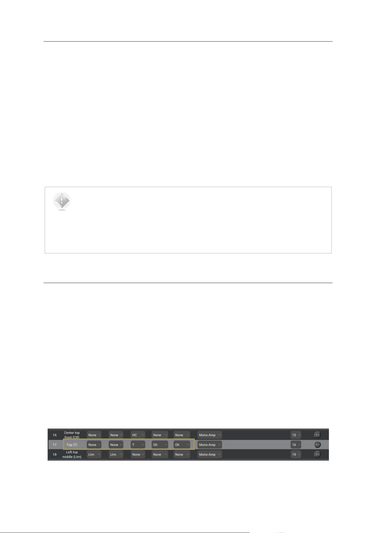
90
8.9 CONFIGURE THE CROSSOVER SETTINGS
(OPTIONAL)
If you want to use the active crossovers of the SDP-75, you must use the speaker configuration table to:
• Specify the type of amplification: bi-amp, tri-amp or quad-amp;
• Specify the crossover frequency
The parameters related to crossover settings are the following:
• Amplification: sets the number of channels of the speaker in case of multi-amplification
• Low freq cut-off: sets the crossover frequencies
• for bi-amp, it is set at 2kHz by default;
• for tri-amp, they are set at 200Hz and 2kHz by default;
• for quad-amp, they are set at 200Hz, 2kHz and 20kHz by default.
NOTES:
• The SDP-75 handles up to 4-way active crossovers.
• The default crossover filters are Linkwitz Riley 4
th
-order (24dB/Oct).
• Advanced crossover settings are available in the Setup/ActiveXovers page of the Advanced
Settings user interface. Further information about the active-crossovers can be found in the
Calibrate the Active Crossovers chapter.
8.10 MAPPING THE CHANNELS OF DIFFERENT
FORMATS
The new Immersive Audio Formats (Auro-3D, Dolby Atmos and DTS:X) come with different channel labels and different
speaker placement recommendations. This causes incompatibility issues that could make it difficult to play the required
content correctly.
In the SDP-75, each speaker can be assigned to a specific channel for each format in such a way that it will play the
required content regardless of the format being decoded.
In the example below, one speaker was set as the “Top” speaker recommendation of Auro Technologies to reproduce
the content of the Auro-3D Top channel (“voice of god”). This channel also exists in DTS:X as the “Oh” channel but does
not exist in the Dolby Atmos format. Therefore, this speaker will not be used during playback of native Dolby Atmos
formats.
Figure#63:##
Channel#mapping#example#for#the#Top#channel#
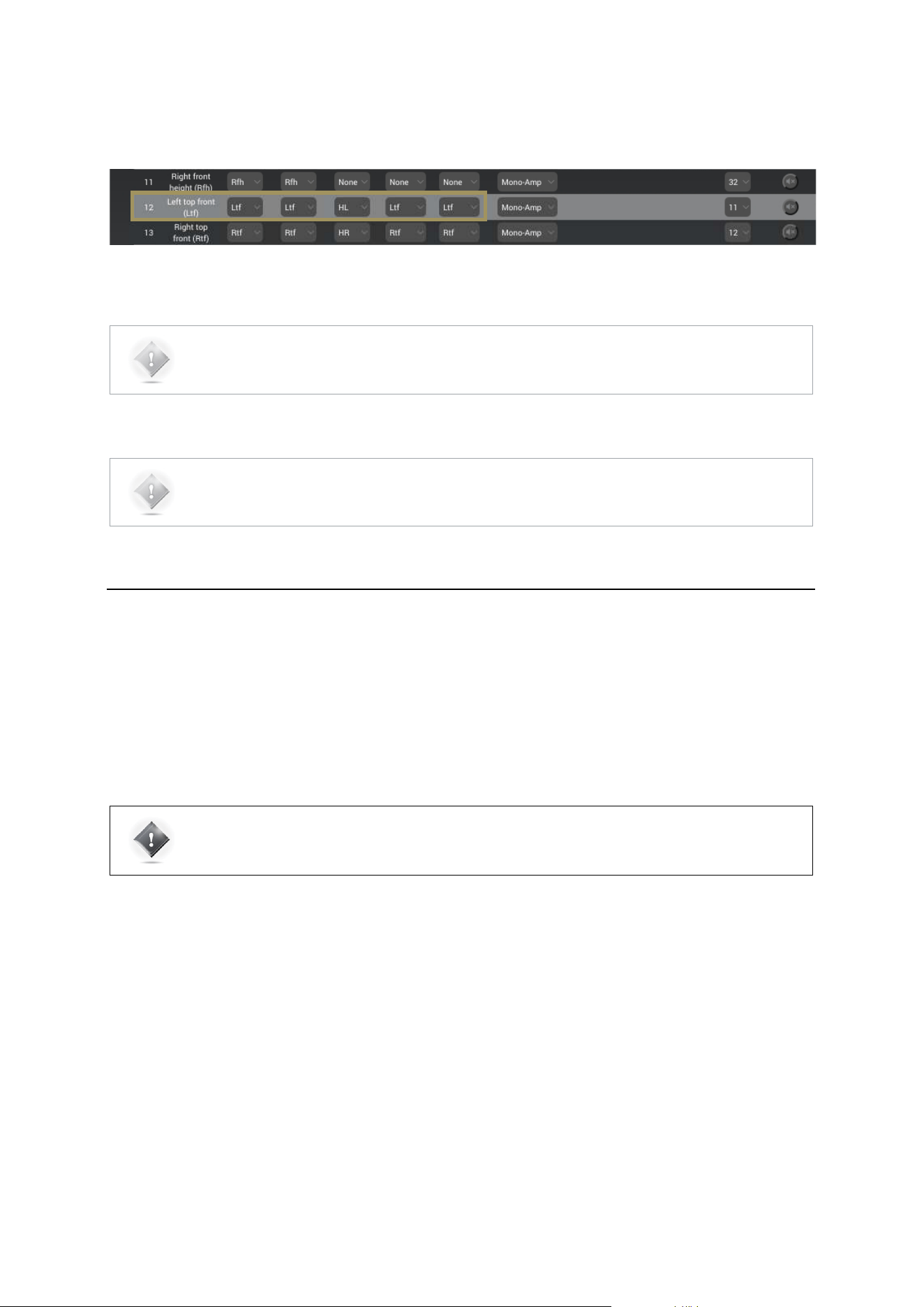
91
In the example below, the SDP-75 has automatically assigned the Left top front (Ltf) channel, initially specified as an
Atmos speaker, to play the Height Left (HL) channel of Auro3D content.
Figure#64:#Channel#mapping#for#the#Left#top#front#(Ltf)#channel#
8.11 SENDING PINK NOISE TO VERIFY THE
ROUTING OF THE SPEAKERS
As soon as the detailed configuration for each speaker is completed, it is critically important to verify that the routing of
the channels to the speakers is correct, and to correct any errors. Otherwise the consistency of the sound reproduction
will be compromised.
IMPORTANT NOTE: This procedure only helps to verify that the routing is correct from the SDP-75 to
the speakers. In addition to this procedure, when a new source is connected to the SDP-75, you should
also verify that the routing is correct from the source to the SDP-75.
To verify the routing of each speaker:
• Select the speaker by clicking in the 3D view or by selecting the corresponding line in the speaker table;
• Click on the Pink Noise icon;
• Locate the speaker through which the pink noise is being played;
• Verify that the playing speaker matches the selected channel in the SDP-75’s Speaker/Room setup tool;
• If there is no match, fix the routing of the speaker by modifying the assigned Output.
NOTE: The channel labels and speaker positions of each format are available in the appendix of this
document.
NOTE: To configure an array of speakers, please refer to the next chapter : Speaker Arrays
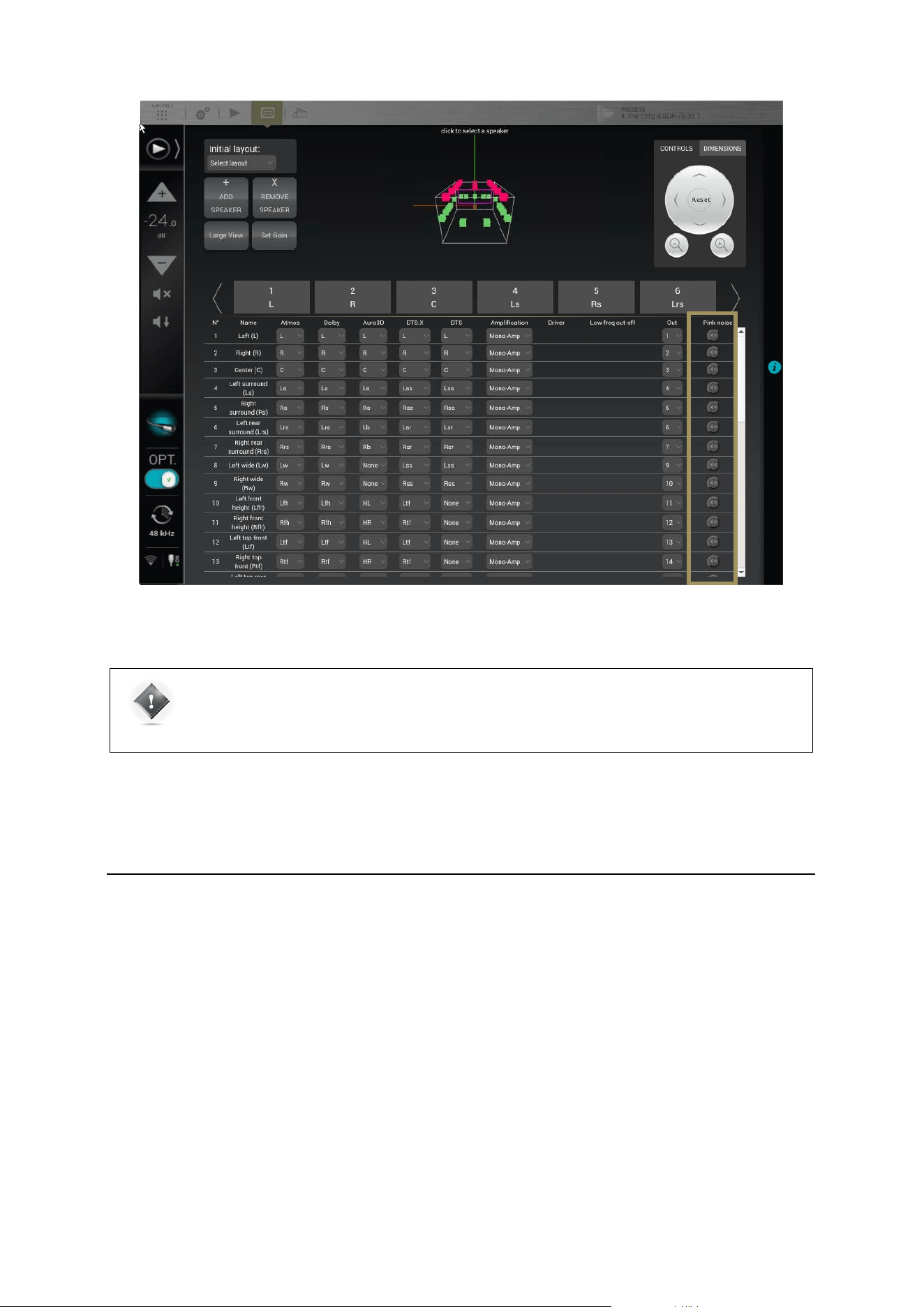
92
Figure#65:#sending#pink#noise#to#the#speakers#
8.12 SAVE THE PRESET
Last but not least, don’t forget to save the preset to make sure the settings of your speaker layout will not be lost.
IMPORTANT NOTE: The SDP-75 needs to be synchronized on an audio clock, either external
(Secondary mode) or internal (primary mode) in order to produce the pink noise. If a Digital source is
selected with
no synchronization signal, the pink noise won’t be produced. In such case, we simply recommend
selecting an analog source.
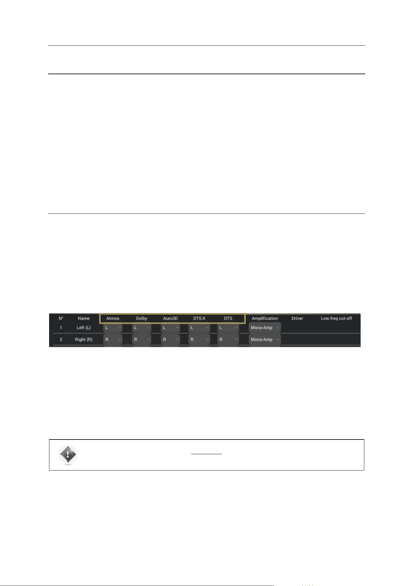
93
9 SPECIFY AN ARRAY OF SPEAKERS
With the release of new 3D audio formats, the number of possible speaker positions increases
considerably. Nevertheless, your video library is surely full of “surround” content (5.1 or 7.1).
Furthermore, 3D formats do not all have the same limitation in terms of simultaneous active
speakers.
So it becomes essential to be able to create an array of speakers: use several speakers to play the
same channel. It is also possible to adjust the gain of each speaker of the array to perfectly match
the needs of the Home-Theater; Thereby, the immersion effect is much more impressive!
Similar configurations have been used in commercial cinemas for years.
9.1 SETTING UP AN ARRAY OF SPEAKERS
Once your speaker’s layout has been declared, configured and fully tested, you can now set up your arrays of speakers.
The SDP-75 is able to duplicate the incoming channel from the decoders on several speakers.
The setup of an array has to be done within the Speaker/Room setup tool, using the mapping column of each decoder.
As explained in the previous chapter Specify a speaker layout, Mapping the channels of different formats section, each
format has its own speaker assignments. You can easily control the number of speakers used by each decoder. Each
column defines the channel used by the associated speaker. In this way, you are able to select the same channel on
several speakers.
In the Speaker/Room setup tool, you can observe five columns giving the details of each decoder’s layout:
• Atmos: Layout used for native Dolby Atmos content and Dolby Surround Up-mixer;
• Dolby: Layout used for Legacy Dolby content;
• Auro-3D: Layout used for Native Auro-3D content and Auro-3D Up-mixer;
• DTS:X: Layout used for native DTS:X content and Neural:X Up-mixer;
• DTS: Layout used for Legacy DTS content.
To specify a speaker layout, please select, in the drop down menu of each speaker, the desired channel that it has to play
for each decoder.
IMPORTANT NOTE: DTS:X is limited to 11 different channels. Nevertheless, you can use the arrays to
duplicate these 11 channels and use more than 11 speakers.
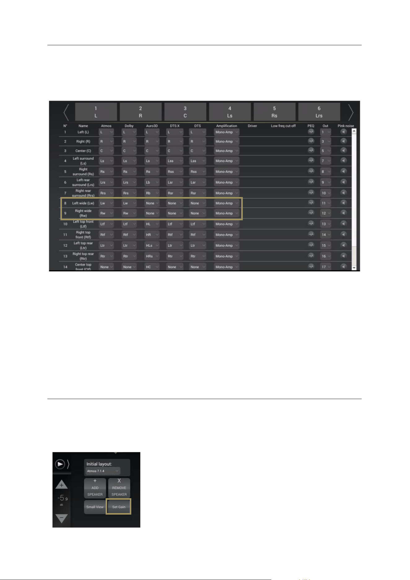
94
9.2 EXAMPLE OF AN ARRAY OF SPEAKERS
Below is an example of a specific speaker layout designed to array some channels:
In the example above, please pay attention to Left Wide and Right Wide speakers:
• For Dolby Atmos content, Left and Right Wide speakers will play natively as they natively existing in the
CODEC;
• For Dolby Legacy content, Left and Right Wide speakers will play Ls and Rs channel, simultaneously with Left
and Right surround speakers;
• For Auro 3D content, Lw and Rw does not exist natively. In this configuration Left and Right Wide speakers will
play Ls and Rs channels simultaneously with Left and Right Surround speakers;
• For DTS:X content, Left and Right Wide speakers will play Lss and Rss channel simultaneously with Left and
Right surround speakers;
• For DTS Legacy content, they will play Lss and Rss channel simultaneously with Left and Right surround
speakers;
9.3 ADJUST THE GAIN
When you decide to make an array, you may need to adjust the gain of each speakers accordingly to each decoder. It is
possible to do it speaker by speaker, or to select a group of speakers to apply the same gain adjustment.
The screen below displays the Set Gain control panel. Each channel assigned from each speakers has a value (default:
0) surrounded by – and + buttons. Use those buttons to adjust the gain in 1dB increments.
To access the speaker’s gain control panel, click on the Set Gain button in
the Speaker/Room setup tool. Instead of the channel assignation, the gain
control will be displayed.
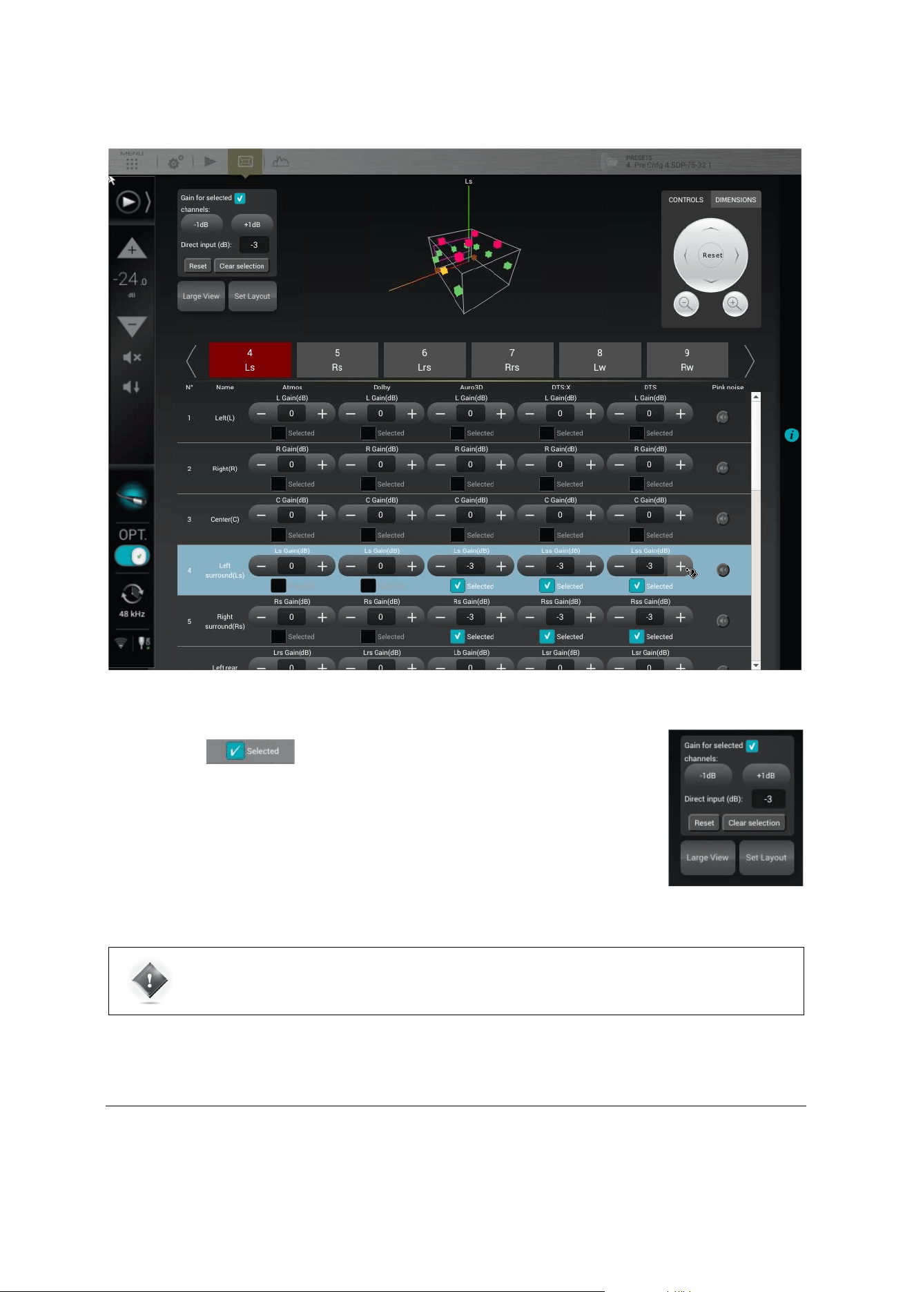
95
By clicking on a value, you also can manually enter a gain. In this case, a virtual numerical keyboard is displayed.
Figure#66:#Set#gain#contro l#p a n e l#
9.4 SAVE THE PRESET
Last but not least, don’t forget to save the preset to make sure the settings of your arrays of speakers won’t be lost.
The Selected speakers can all be modified simultaneously using the
control panel in the top left corner.
You can add or decrease gain using -1dB or +1dB buttons, or by using the Direct input and
its numerical keyboard.
The Reset button clears any modification and sets the default value of 0dB.
The Clear selection unselects every speaker, keeping the modified values.
IMPORTANT NOTE: High gain values can damage a speaker.
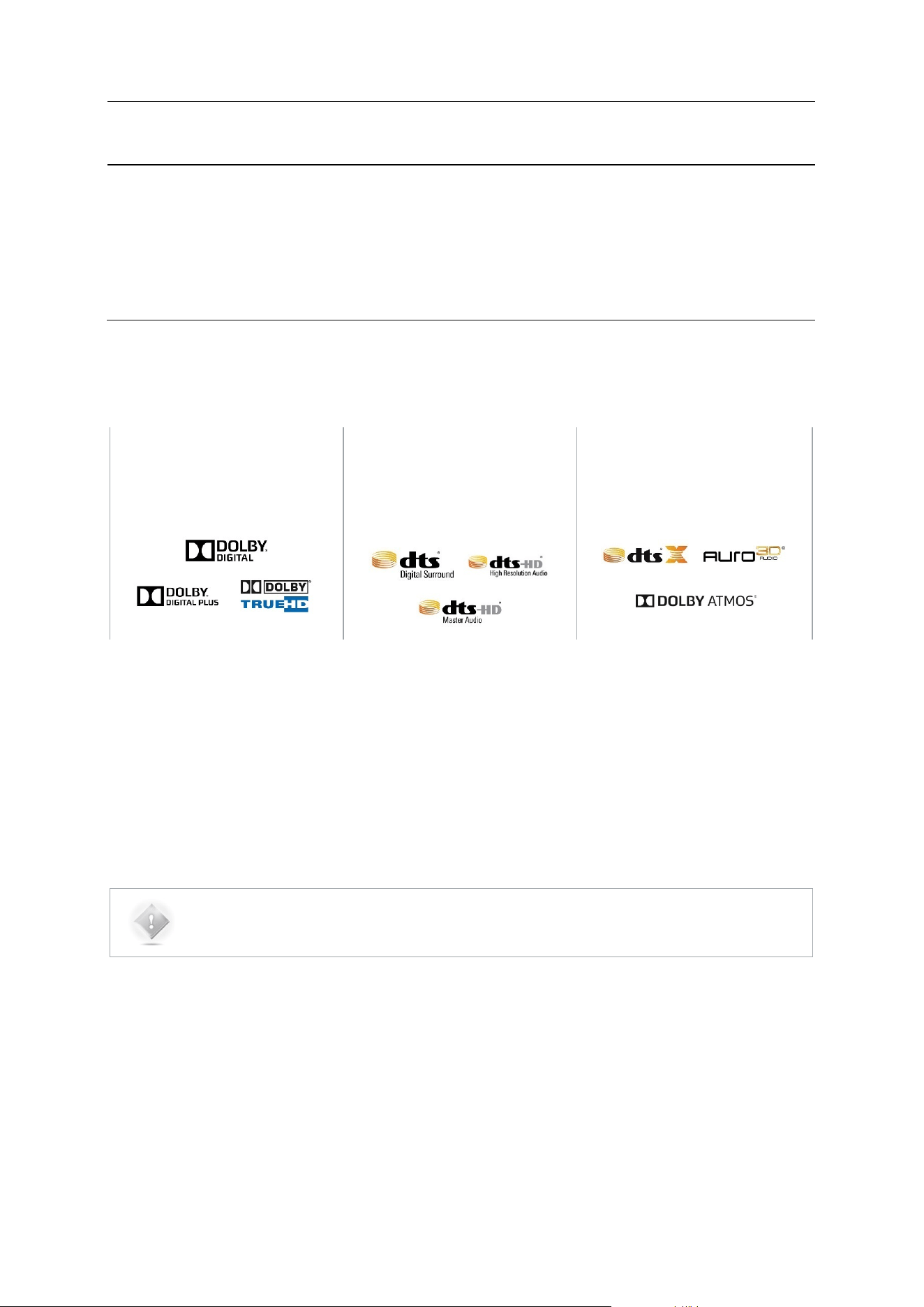
96
10 DECODER / UP-MIXER SETTINGS
The SDP-75 allows you to enjoy various kinds of surround and stereo playback modes using the decoders mentioned
below. With the 3D codecs option, you also are able to extend your stereo or basic multichannel content (5.1/7.1) to a
full 3D sound, and so use most of the speakers specified in the setup procedure. These are the Up-mixers:
10.1 SUPPORTED DECODERS/UP-MIXERS
A number of surround and 3D decoders are implemented in the SDP-75:
Dolby decoders:
DTS decoders:
3D decoders:
Dolby Digital
Dolby Digital Plus
Dolby TrueHD
DTS Digital Surround
DTS-HD High Resolution Audio
DTS-HD Master Audio
Dolby Atmos
DTS:X
Auro-3D
With the 3D option, the SDP-75 also supports the following surround Up-mixers:
Dolby Surround
®
DTS Neural:X
®
Auro-Matic
®
NOTE: Some speakers are not utilized by every decoder. In this case, they will remain silent while this
decoder is active. For example, the “Top” speaker is not used by Dolby Atmos, so this speaker will only
be used while playing DTS:X and Auro-3D content, and also if you use their respective up-mixer.
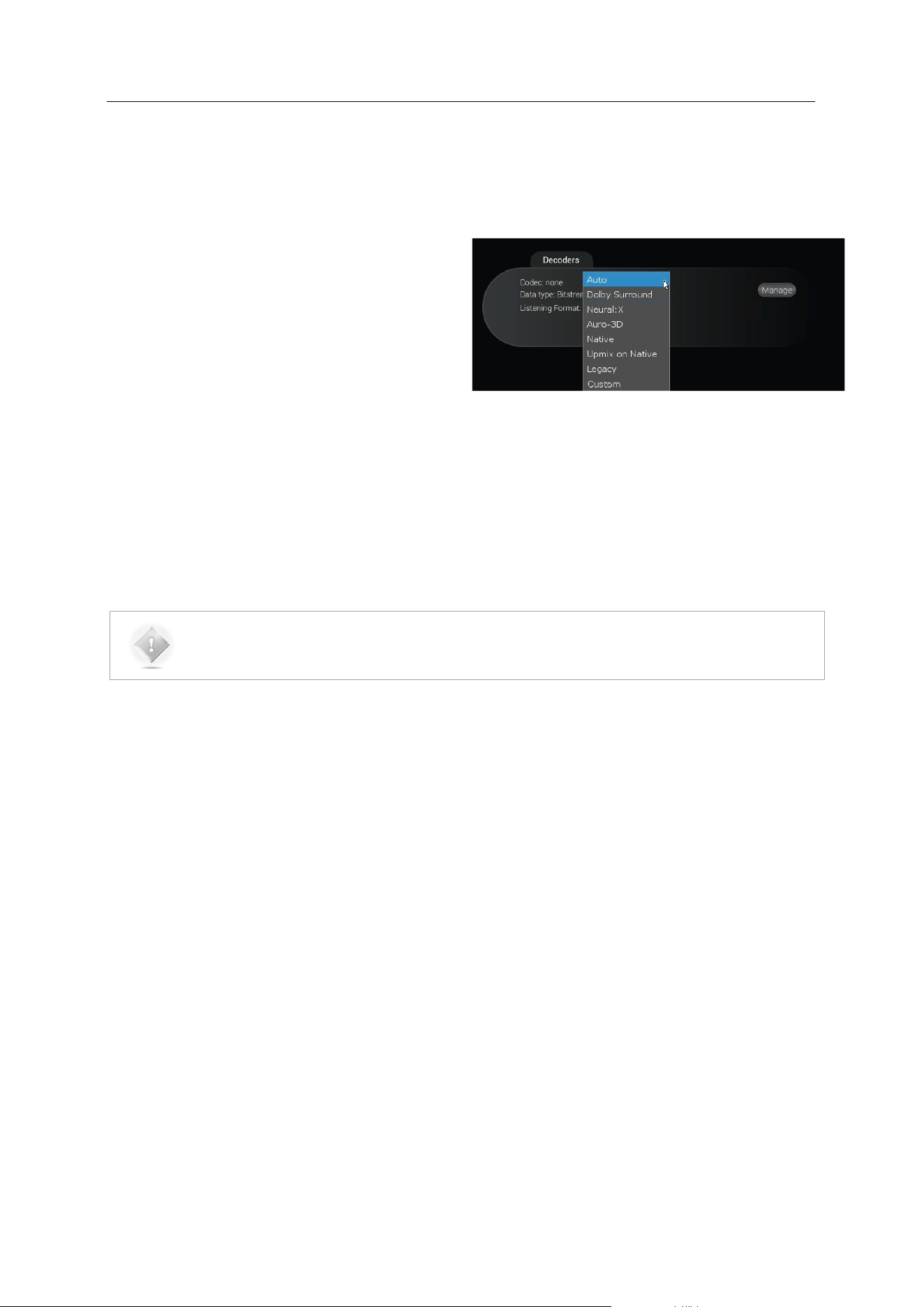
97
10.2 LISTENING FORMATS
The Listening Format dropdown menu provides you several options. Some of them may sound familiar to you, while the
others could be unknown. The list gives you:
• Auto: The incoming encoded content will be played
with the corresponding up-mixer.
• Dolby Surround: The incoming content will be
played using the Dolby Surround up-mixer.
• Neural:X: The incoming content will be played using
the DTS Neural:X up-mixer.
• Auro-3D: The incoming content will be played using
the Auro-3D up-mixer.
• Native: The incoming content won’t be modified and will be played as it is.
• Up-mix on Native: The incoming content will played using the corresponding up-mixer, but with the Legacy
speaker layout (Dolby or DTS column).
• Legacy: This listening format will only play the “bed” layout of the content (5.1 or 7.1) and will ignore the 3D
layout.
• Custom: You are not able to select this mode manually, but it is automatically selected as soon as you change
any of the decoder’s settings.
NOTE: Depending of the incoming format decoded by the SDP-75, the listening format listed above will
exhibit different behaviors. Please read the chart below carefully, which indicates the behavior of each
listening format relative to the source format.

98
Source format
Up-mix mode
PCM
Dolby (DD, DD+, TrueHD)
Native
Dolby Atmos
DTS
(Legacy, HD Master
Audio)
DTS:X
Native
Auro-3D*
Auto
None (No Up-mix) |
Layout used :
Selected in
Decoder General
settings
Dolby Surround Up-
mixer | Layout Used :
Atmos
Native Dolby Atmos |
Layout Used : Atmos
Neural:X Up-mixer |
Layout Used :
DTS:X
Native DTS:X |
Layout Used :
DTS:X
Native Auro-3D (2) |
Layout Used: Auro-3D
Dolby Surround
Dolby Surround Up-
mixer (1) |
Layout Used :
Atmos
Dolby Surround Up-
mixer | Layout Used :
Atmos
Native Dolby Atmos |
Layout Used : Atmos
Dolby Surround Up-
mixer | Layout Used
: Atmos
Native DTS:X |
Layout Used :
DTS:X
Dolby Surround Up-
mixer | Layout Used :
Atmos
Neural:X
Neural:X Up-mixer |
Layout Used :
DTS:X
Neural:X Up-mixer |
Layout Used : DTS:X
Native Dolby Atmos |
Layout Used : Atmos
Neural:X Up-mixer |
Layout Used :
DTS:X
Native DTS:X |
Layout Used :
DTS:X
Neural:X Up-mixer |
Layout Used : DTS:X
Auro-3D
Auro-3D Up-mixer
(1) | Layout Used :
Auro-3D
Auro-3D Up-mixer |
Layout Used : Auro-3D
Native Dolby Atmos |
Layout Used : Atmos
Auro-3D Up-mixer |
Layout Used : Auro-
3D
Native DTS:X |
Layout Used :
DTS:X
Native Auro-3D* |
Layout Used: Auro-3D
Native
None (No Up-mix) |
Layout used :
selected in Decoder
General settings
None (No Up-mix) |
Layout Used : Dolby
Native Dolby Atmos |
Layout Used : Atmos
None (No Up-mix) |
Layout Used : DTS)
Native DTS:X |
Layout Used :
DTS:X
Native Auro-3D* |
Layout Used: Auro-3D
Up-mix on Native
Up-mix following
the default PCM
layout in the
Decoder General
settings
Dolby Surround Up-
mixer | Layout Used :
Dolby
Native Dolby Atmos |
Layout Used : Atmos
Neural:X Up-mixer |
Layout Used : DTS
Native DTS:X |
Layout Used :
DTS:X
Native Auro-3D* |
Layout Used: Auro-3D

99
Figure'67'Chart'of'the'behavior'between'source'format'and'listening'mode'
Legacy
None (No Up-mix) |
Layout used :
selected in Decoder
General settings
None (No Up-mix) |
Layout Used: Dolby
Bed (Original 7.1) |
Layout Used : Dolby
None (No Up-mix)
(2) | Layout Used :
DTS
Bed (Original 7.1) |
Layout Used : DTS
Bed (Original 7.1) |
Layout Used : Auro-3D
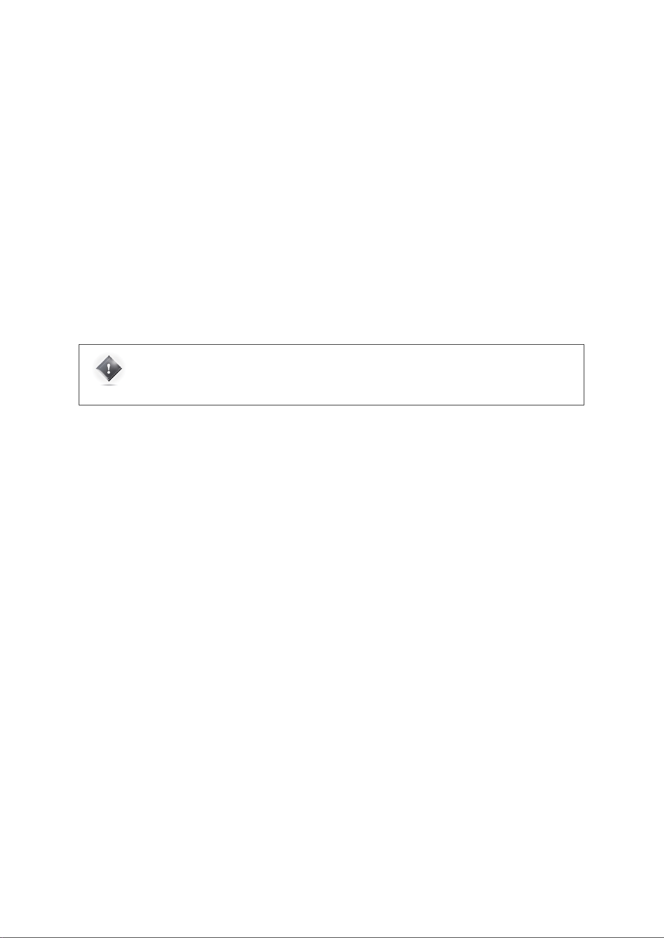
100
KNOWN ISSUES
(1) Potential issue with stereo PCM sources (typically CD): the HDMI outputs of some Blu-Ray players declare 7.1
channels instead of 2. In such case, surround and rear channels will not be up-mixed. This issue comes from the player,
not from the SDP-75. The only solution is to force the player to deliver 2 channels.
(2) Potential issue with Auro-3D content: Auro-3D may not be detected in Listening Format Auto. In such cases, the up-
mixer of the Bed format will be used. If it is Auto-3D PCM material, the up-mixer used will depend of the PCM default
layout selected in the Decoders General Settings. If this happen, selecting Auro-3D listening format will play Native Auro-
3D content.
CPU LOAD: Do not forget that Up-mixers require a lot of CPU resources, especially in 96 kHz with high channel count.
Auro-Matic: The Auro-3D up-mixer does operate up to 96 kHz but not with higher sampling rates.
Neural:X: The Neural:X up-mixer does operate up to 48 kHz but not with higher sampling rates.
• * Please refer to the important note below.
For detailed information about the surround up-mixers, please contact the JBL Synthesis Support Team.
IMPORTANT NOTE: Sometimes, in Auto or Native listening format, Auro-3D content may not be
correctly detected and decoded at the input. In this situation, only 5.1 or 7.1 content will be considered.
If so, please set the Listening Format on Auro-3D to ensure the complete Auro-3D decoding. This
behavior will be solved in a future software release.
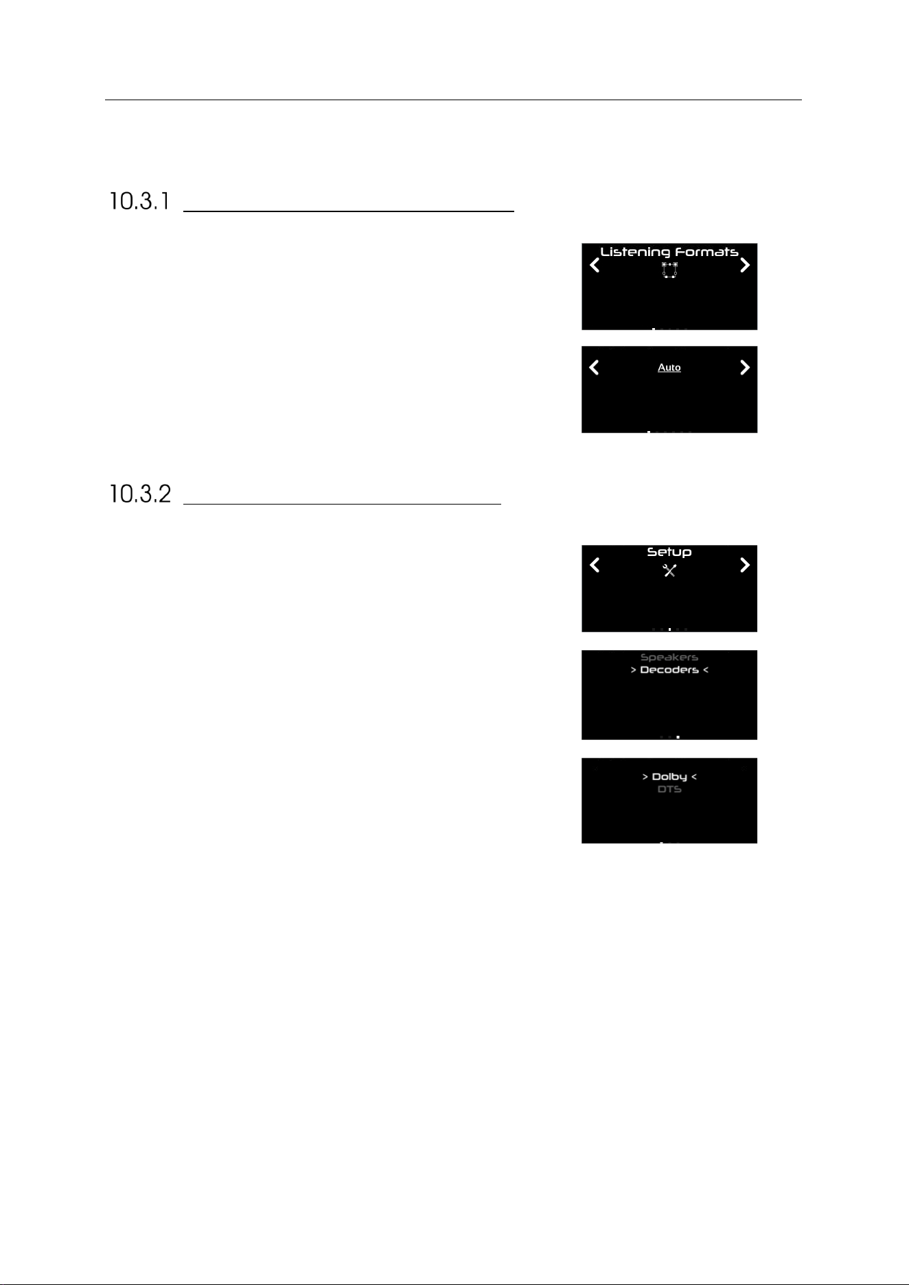
101
10.3 USING THE FRONT PANEL
LISTENING FORMAT SELECTION
From the front panel of the SDP-75, press the Menu button. Using the
Select knob, navigate to the “Listening Format” menu, confirm using the
Enter button.
Then choose the desired listening format, still using the Select knob, and
confirm using the Enter button. The current listening format is
underlined.
DECODERS CONFIGURATION
To configure the Decoders from the front panel, press the Menu button.
Using the Select knob, go to the Setup menu. Confirm using the Enter
button.
Then, using the Select knob, go down the list and select Decoders, and
confirm with the Enter button.
Finally, select the decoder you want to configure, and confirm with the
Enter button. .
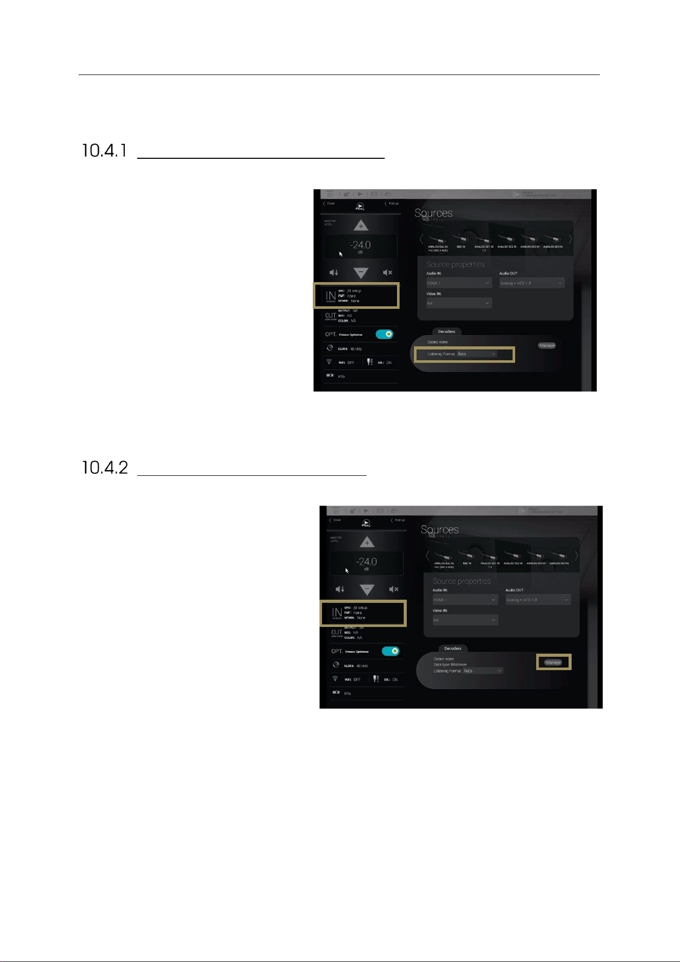
102
10.4 USING THE GRAPHICAL INTERFACE
LISTENING FORMAT SELECTION
To activate a surround up-mixer:
1. Click on the “IN sources” menu item of
the lateral menu to go to the Sources
page;
2. Select a Listening Format in the drop
down list.
Figure'68:'The'surround'up-mixer'option'
DECODER CONFIGURATION
To configure the decoder parameters for the Dolby,
DTS and Auro-3D decoders:
1. Click on the “IN sources” menu item of the
lateral menu to go to the Sources page;
2. In the Sources page, click on the Manage
button in the Decoders section. This gives
you access to the decoders settings
described below.
Figure'69:'Accessing'the'decoders'setup'from'the'Sources'page'
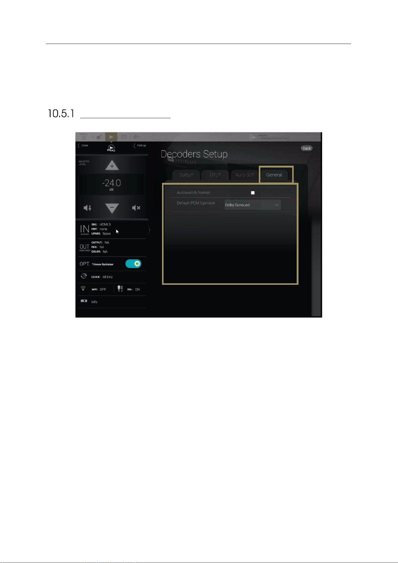
103
10.5 DECODERS SETTINGS
The different decoders’ settings given below are available through the graphic interface or through the front panel screen
(see above).
GENERAL SETTINGS
The General tab provides you different settings to configure the decoding behavior of the SDP-75 that does not directly
concern the decoders.
• Autoswitch format : When this option is activated, the SDP-75 will
automatically switch to the input format of the decoder. The SDP-75 virtually
replaces the speakers at their ideal position recommended by the curent
decoder and provides you the best immersive conditions.
If this setting is not enabled, you must manually select a desired source
format in the Setup/Source menu of the Advanced interface.
• Default PCM Up-mixer : The PCM format has no decoder, thus there is no
assign speaker layout. This setting allows the assignment of a default layout
and up-mixer for incoming PCM content.
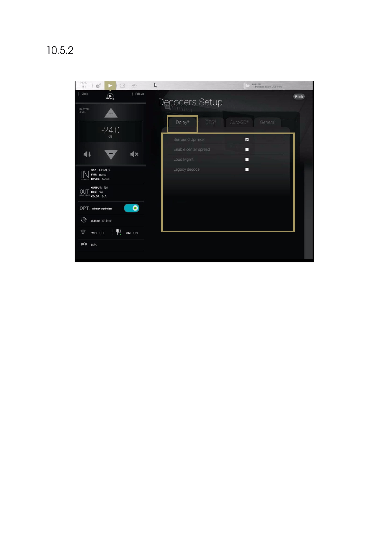
104
DOLBY DECODER SETTINGS
Figure'70:'Dolby'decod e r's ett in gs '
• Surround Up-mixer: switch on/off the Dolby surround up-mixer;
• Enable center spread: spread the Center channel across the Left and Right speakers. Creates a wider sound
stage, recommended for playing musical content;
• TrueHD Loudness Management : use the loudness management information provided in the incoming signal’s
metadata;
o DRC Settings:
§ Auto: Automatic DRC low level boost and high level cut;
§ Enabled: Enable the Dynamic Range Control management;
§ Disabled: Disable the Dynamic Range Control management;
o DRC Low-Level Boost: Amount of low-level boost;
o DRC High-Level Cut: Amount of high-level cut;
• Legacy decode: extract the legacy content (5.1 or 7.1) from the incoming Dolby Atmos content.
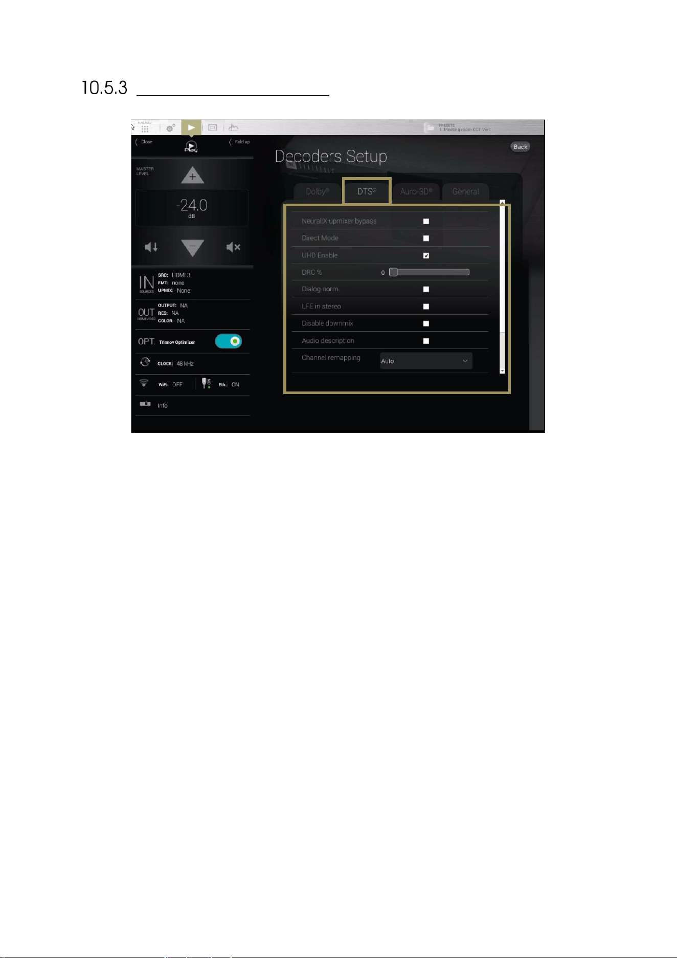
105
DTS DECODER SETTINGS
Figure'71':'DTS:X'Deco d e r'S et tin g s'
• Neural:X Up-mixer Bypass: Disables the Neural:X Up-mixer;
• Direct Mode: In “Direct Mode,” the audio is extracted and reproduced as closely as possible to what the
content creator intended. At a high-level, direct mode attempts to most closely preserve the original speaker
layout with no additional processing to take advantage of additional speakers;
• UHD Enable: Allows rendering the 3D object. If this function is disabled, the decoder will play only on legacy
(5.1/7.1) speakers;
• DRC%: sets a percentage of Dynamic Range Control ;
• Dialog norm: use the incoming metadata to adjust the level of the center channel;
• LFE in stereo: send the LFE to a pair of subwoofers ;
• Disable down-mix: Do not down-mix surround formats into stereo;
• Audio description: switch on the visual description track intended for the blind and visually impaired ;
• Channel remapping: This setting is only applicable for surround formats
o None : No channel remapping is applied
o Auto: apply automatic channel remapping that matches the incoming channels to the speaker
system;
o Auto on DTS configs: apply automatic channel remapping accordingly to some specifics speakers
configurations determined by DTS
o 2.0 – 7.1 settings: force playback on a specific speaker configuration such as 7.1 independently
from the incoming channels;
• Solo stream: enable the Primary or Secondary solo stream.
• Interactive Object: If interactive objects are available on the content in use, a slider will provide a volume
control on these interactive objects. The slider is disabled if no interactive objects are available. The
interactive objects are usually dialog objects, therefore you are able to adjust the dialog level.
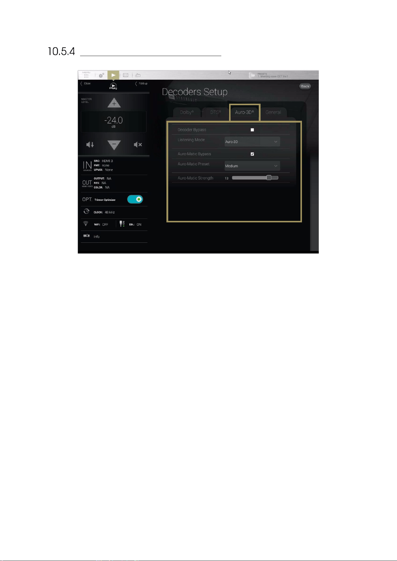
106
AURO-3D DECODER SETTINGS
Figure'72:'Auro-3D'decoder'settings'
• Decoder bypass: bypass the Auro-3D decoder;
• Listening mode:
o Auro-3D: enforce playback on the Auro-3D speaker layout. Incoming surround content is up-mixed
to the Auro-3D format ;
o Surround: enforce playback on the surround speaker layout, so that height speakers are disabled.
Incoming stereo content is up-mixed to a surround format and incoming Auro-3D content is down-
mixed to a surround format.
o Stereo: enforce playback in stereo. Incoming surround content is down-mixed to the stereo format.
• Auro-matic Bypass: switch on/off the Auro-matic up-mixer;
• Auro-matic Preset: choose different settings for the Auro-matic up-mixer;
• Auro-matic Strength: sets the strength of the Auro-matic up-mixer.

107
11 PREPARING FOR CALIBRATION
This chapter explains very important tips to ensure a smooth and safe calibration process, as well as
important recommendations for microphone placement in order to perform high quality
measurements.
11.1 VERY IMPORTANT TIPS
Important Notes:
• Active Crossovers need to be calibrated prior to Optimizer, Level, or Delay Adjustments.
• Primary 48 kHz clock modes should be used for measurement. (Factory default for
the microphone input.)
Avoiding feedback loops:
• Always MUTE the processor as the first step of the calibration procedure. Muting the outputs does not affect the
calibration signal.
• Be careful with feedback issues when you change the routing you could make dangerous feedback loops between
the microphone and the loudspeakers.
Avoiding warning messages during calibration:
• Disable the subwoofer’s built-in filters: a narrow bandwidth can disturb the measurement.
• Adjust levels between amplifier/active speakers before calibration to avoid dangerous level jumps.
11.2 CHECKLIST BEFORE YOU START
Please go through the following checklist to make sure you are ready to start the calibration process:
• You’ve read carefully the whole chapter about the SDP-75’s Essential Tools and Settings that you’ll be using
throughout the calibration process.
• The speaker layout (including multi-amplified speakers) has been specified in the SDP-75 Speaker/Room
Setup Tool.
• The routing of the speakers/drivers has been verified by playing pink noise with the SDP-75 Speaker/Room
Setup Tool.
• All the speakers (including the subwoofers) are installed in their final positions and orientations, and connect
ed
to their amplifiers in the proper polarity.
• The measurement microphone is switched OFF, placed securely on a mic stand or camera tripod, and
connected to the SDP-75 MIC input.
• The MIC input is selected as a source for a 5 pin XLR microphone, or ANALOG BAL IN 1+2 (MIC 4 XLR) for a 4
XLR microphone
• You have access to the Advanced Settings user interface via a screen directly connected to the SDP-75, or
through a VNC client.
108
11.3 IMPORTANT RECOMMENDATIONS FOR
MICROPHONE PLACEMENT
REQUIREMENTS FOR THE MEASUREMENT ENVIRONMENT
At least a few basic rules should be respected to ensure a robust measurement:
• No obstacle between the speaker and the microphone.
• No highly reflecting surface (leather sofa, glass table…) close to the microphone.
• No background noise during the measurements (Air conditionning, open doors, windows etc…)
• No movement during the calibration (disturbs speaker localization)
REFERENCE MEASUREMENT POINT
The SDP-75 supports single-point and multi-point calibrations. In both scenarios, a reference measurement position
should be chosen carefully since it will be used by the Optimizer for:
• Cross-over driver alignment
• Loudspeaker relative delay/level alignment
• Master delay/level calculation
POSITION AND ORIENTATION OF THE MICROPHONE FOR
THE REFERENCE POINT
The calibration microphone should be placed at the listening position, using the listener’s ears as a reference for its
height. A red led shows the front of the microphone. The red led must be pointed to the front of the sound stage, towards
the center speaker.
During the calibration process the microphone should be attached to a microphone stand or a camera tripod.
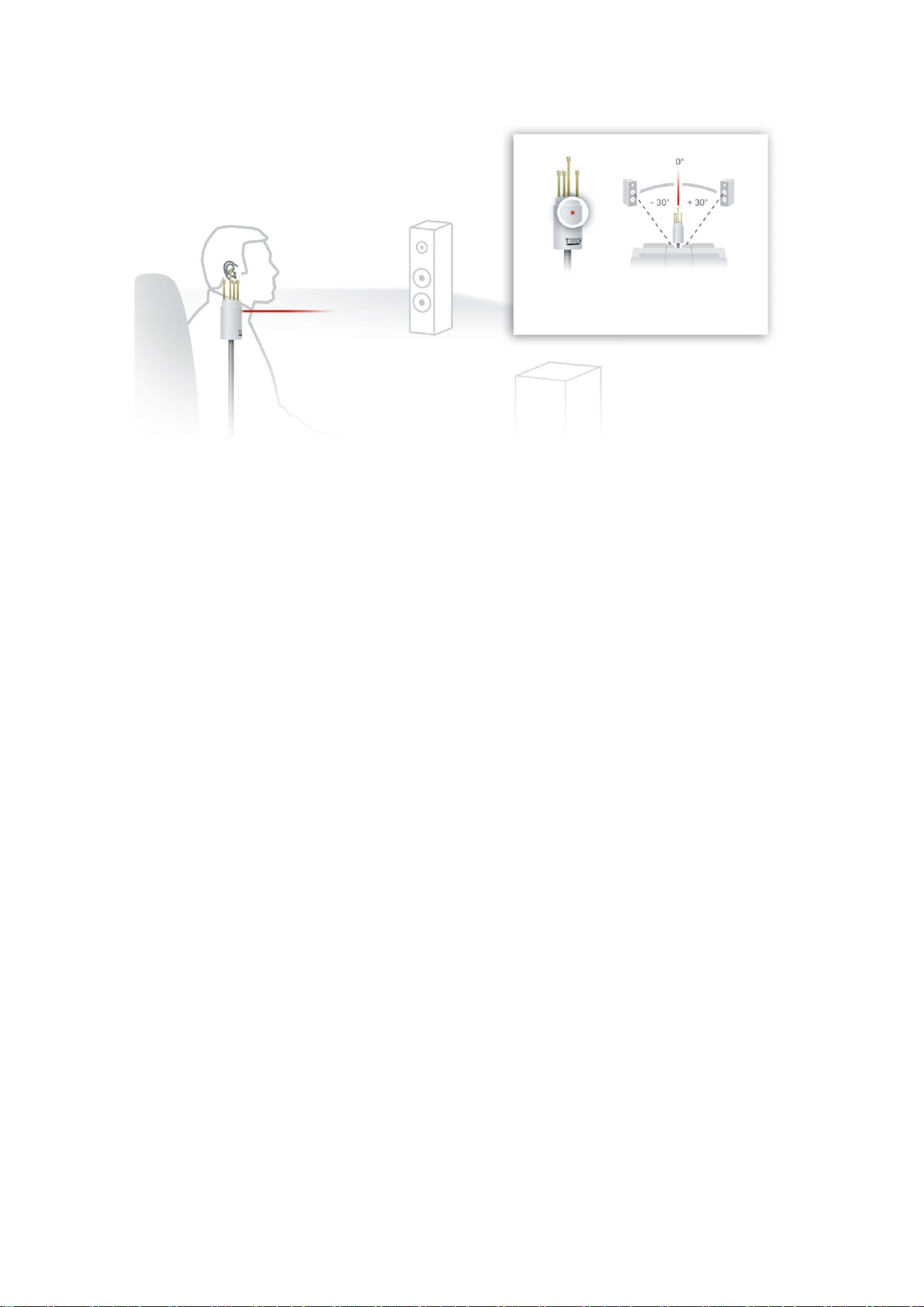
109
Figure'73:'Microphone 're fe ren c e'p o sit ion'
Point the front red LED
to the center of the speakers.
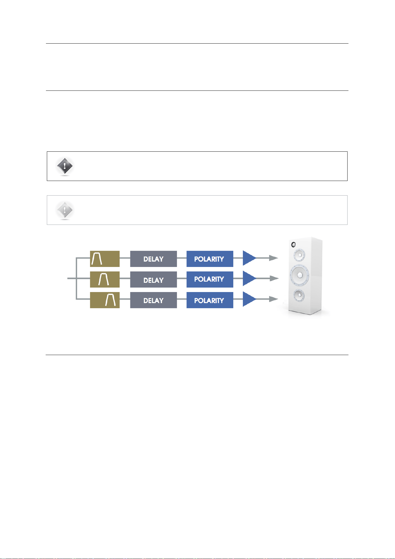
110
12 CALIBRATE THE ACTIVE
CROSSOVERS (OPTIONAL)
This chapter explains how to calibrate the active crossovers included in the SDP-75. It assumes that
you are familiar with active crossovers and multi-amplified speakers, and is not intended as a
course. If you are not using the active crossover functionality of the SDP-75, please skip to
the next chapter.
IMPORTANT NOTE: Carefully read carefully the entire chapter about the SDP-75 Essential Tools and
Settings that you will be using throughout the calibration process.
NOTE: Primary 44.1 kHz or 48 kHz clock modes should be used for calibration (Primary 48kHz
highly recommended).
Figure'74:'Overview'of'the'active'crossovers'signal'flow'
12.1 OVERVIEW OF THE CROSSOVER SETUP
PROCEDURE
The overall setup and calibration process of the SDP-75 active crossovers is performed through two different tools:
• Use the Speaker/Room Setup Tool to:
• Configure the number of ways and the crossover frequencies;
• Verify the routing of the SDP-75 outputs to the correct drivers.
• Use the Setup/Active Xovers page of the Advanced Settings interface to:
• Configure the advanced crossover settings such as specific frequencies for each driver and the type of filter
s
(optional);
• Use the Processor/Meters page to adjust the master output level;
• Perform the automated calibration of the active crossover: this will automatically determine the level, delay and
polarity of each driver;
• Manually adjust levels, delays and polarities of each driver.
The first 2 steps of this process were explained in the previous chapter. This chapter explains the next steps.
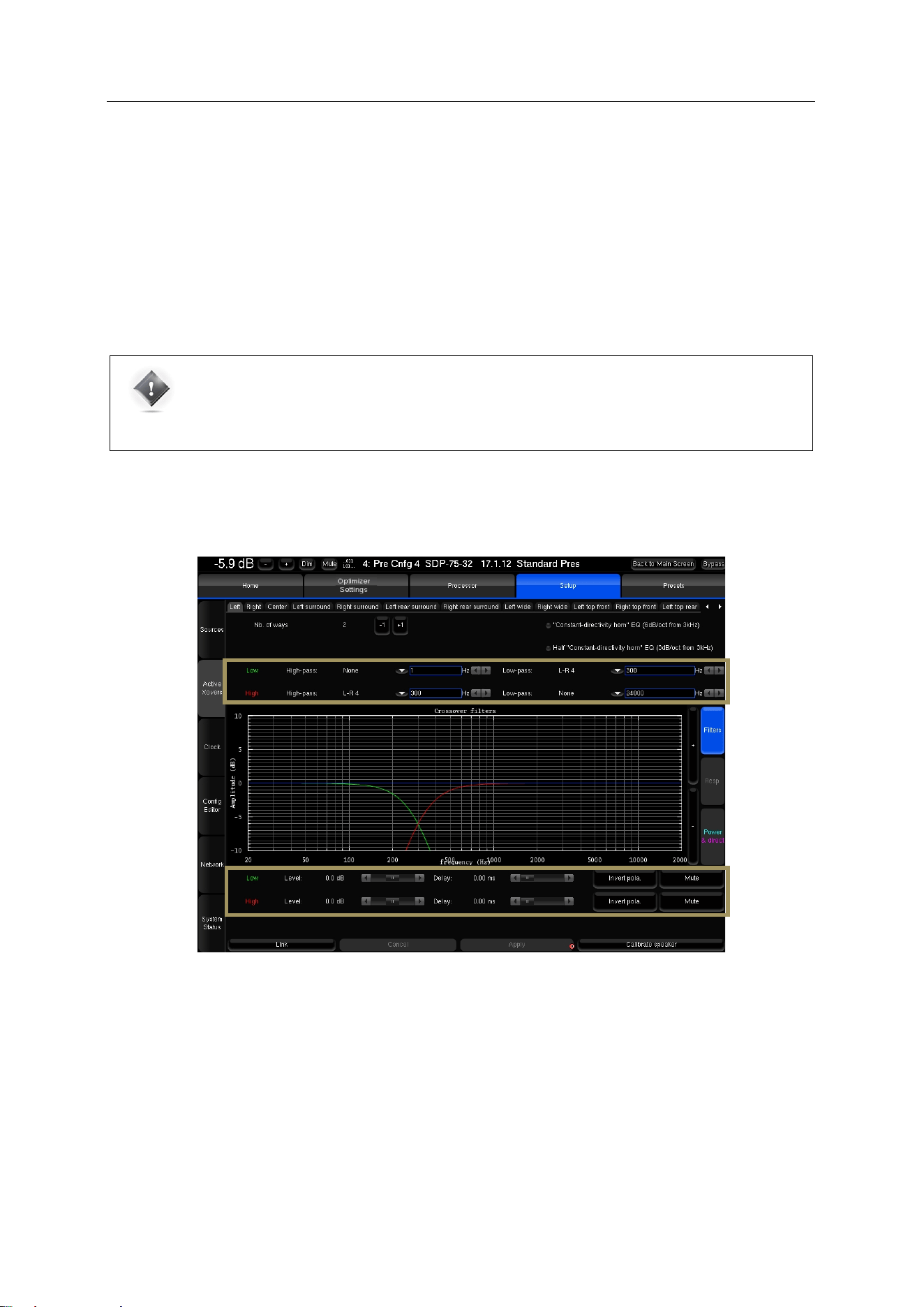
111
12.2 CONFIGURE THE ADVANCED SETTINGS
(OPTIONAL)
The SDP-75 includes the following advanced crossover settings:
• Types of filters: 2
nd
, 3
rd
, and 4
th
-order Bessel, 2
nd
and 4
th
-order Linkwitz-Riley,
and 2
nd
, 3
rd
, and 4
th
-order Butterworth;
• Specific crossover frequency for each driver;
• Level, Polarity and Delay adjustment on each way (driver);
IMPORTANT NOTE: Setup of the crossover filters can be done simultaneously for multiple speakers
thanks to their respective Link button. Linking has to be done before changing parameters.
Please refer to the speaker manufacturer’s specifications to determine the type of filters and crossover
frequency.
The Setup/Active Xovers page displays one tab for each loudspeaker. The number of loudspeakers displayed depends
on the number of loudspeakers specified in the Speaker/Room Setup tool.
Figure'75:'advanced'crossover'settin g s'
The following settings are available for each loudspeaker:
• The type of high-pass or/and low-pass filters is chosen in the dropdown menu using !
• The cut-off frequency of each filter is set by using the | arrows } or by manually entering the frequency
• Level and delay can be adjusted on each way (driver),
• Mute and Invert Polarity buttons are also available.
• Two additional IIR filters are available under the name of “Constant-directivity horn” EQ and Half “Constant-
directivity horn” EQ . The purpose of such filters is to boost the high frequencies for speakers that use constant-
directivity horns. These speakers tend to have too little energy at the highest frequencies in the sweet spot.
Depending on the horn you are using, you may want to boost the high frequencies by 3 or 6 dB/oct, from about 3kHz.
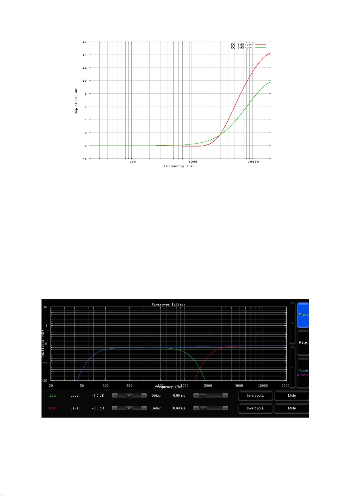
112
Figure'76:'“Constant-directivity'horn”'EQs'
• The Apply button is highlighted as soon as a parameter is modified and is used to compute and load the
new settings into the processor. Once compute is finished, the gears icon disappears from the notification
bar, and filters are applied to the outputs.
• If the changes are unwanted, press the Cancel Changes button to cancel your modifications.
• If change is accepted, press the Save button of the preset of your choice in the Presets page to save the
changes; otherwise, changes will be lost.
The theoretical model of the specified filters is represented as follows:
• The green curve represents the theoretical low-pass filter response
• The red curve represents the theoretical high-pass filter response
• The blue curve represents the theoretical resulting response of the speakers
Figure'77:'Theoretical'model'of'the'specified'filters'
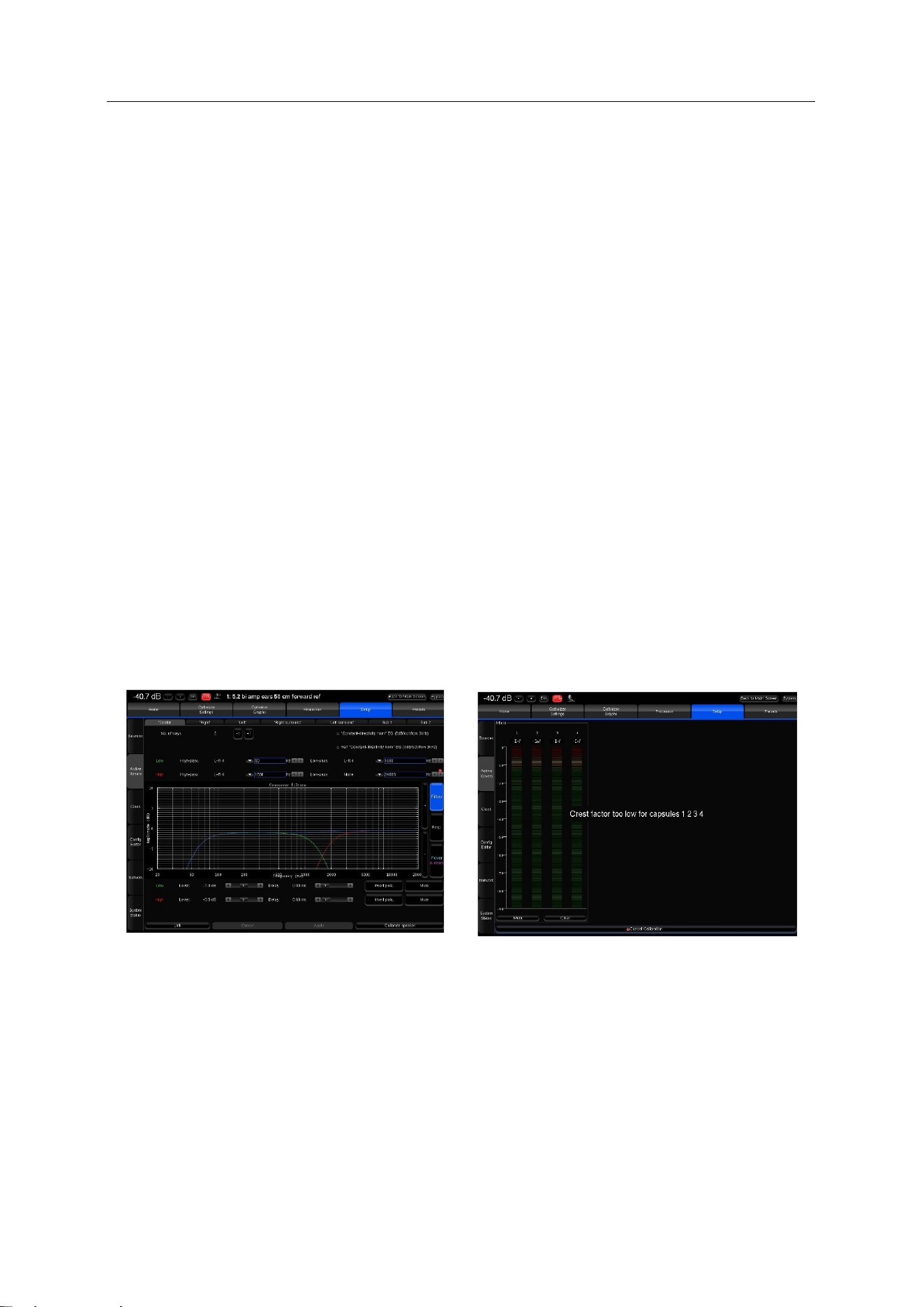
113
12.3 ADJUST THE MASTER OUTPUT LEVEL
The SDP-75 requires a minimum Sound Pressure Level for proper calibration of the active crossovers. Until that
minimum SPL is reached, the test signal will keep playing through the same driver.
First, be sure that you selected the proper microphone input: Analog MIC
• Set a safe output level:
1. Decrease Master Level to -40 dB;
2. Press the Mute button to cut the outputs (this step must ALWAYS be performed before pressing on
the Calibrate button to avoid a feedback loop);
3. Switch on the microphone preamp;
4. Press the Calibrate button in the Setup/ActiveXovers page of the Advanced Settings interface.
• Adjust output level:
1. Increase the master level until the test signal moves to the second driver;
2. Use the SDP-75’s metering tools, which are automatically displayed on screen to check the level of
the microphone inputs;
3. Use your ears to evaluate the perceived SPL of each driver and, if possible, increase the master
output level to ensure that an optimal SPL is reached for all the drivers. This will also improve the
quality of your measurements;
4. Use the Cancel button to stop the calibration (optional).
Figure'78:'Crossover'calibration'pag e '
Figure'79:'Metering'page'
Once the level is adjusted, you can move to the next step to perform the final calibration of the active crossover.
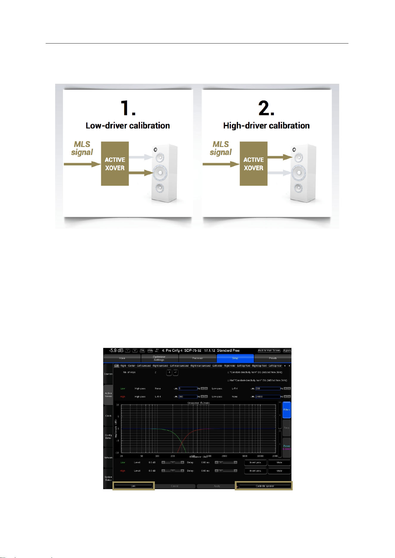
114
12.4 CALIBRATE THE ACTIVE CROSSOVERS
Figure'80:'the'steps'of'the 'ca lib r at io n 'p ro c e ss'
Once the master output level is set (see previous step), the SDP-75’s crossover calibration tool will automatically set up
the level, delay and polarity of each driver.
Before calibration, please note:
• The calibration procedure has to be done individually for each speaker;
• An MLS signal is sent to each driver of the selected speaker when the Calibrate button is selected;
• At the end of the calibration process, a warning message states that a new calibration of the entire system is
required.
Figure'81:'Performing'the'calibration'of'the'active'crossovers'
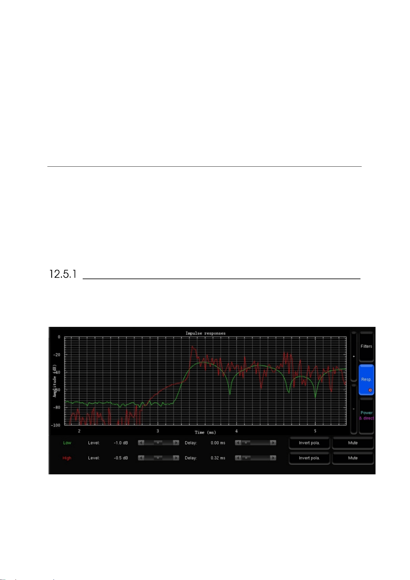
115
Remain in the Setup/ActiveXovers page of the Advanced Settings interface to perform the calibration of the active
crossovers:
• If two or more speakers are linked, please unlink them by turning off the Link button.
• Follow the microphone placement instructions (see previous chapter).
• Make sure the measurement environment is silent.
• Press the Mute button to cut the outputs (this step must ALWAYS be performed before pressing on the Calibrate
button)
• Press the Calibrate button in the Setup/ActiveXovers page of the Advanced Settings interface
• Follow the on-screen instructions regarding the microphone.
12.5 VERIFY THE SOUND OF THE CALIBRATED
CROSSOVERS
Once the calibration of the active crossovers is finished, it is critically important to verify the sound of the related
speakers to identify any possible issues:
• Visualize the acoustic graphs of the speakers connected to the active crossover;
• Listen to the speakers connected to the active crossover.
VISUALIZE THE ACOUSTICAL GRAPHS FOR EACH SPEAKER
You can visualize the results in two forms:
• The measured impulse response of each channel: You can see whether the drivers are correctly synchronized.
Figure'82:'Measured'impulse'response'of'both'drivers'
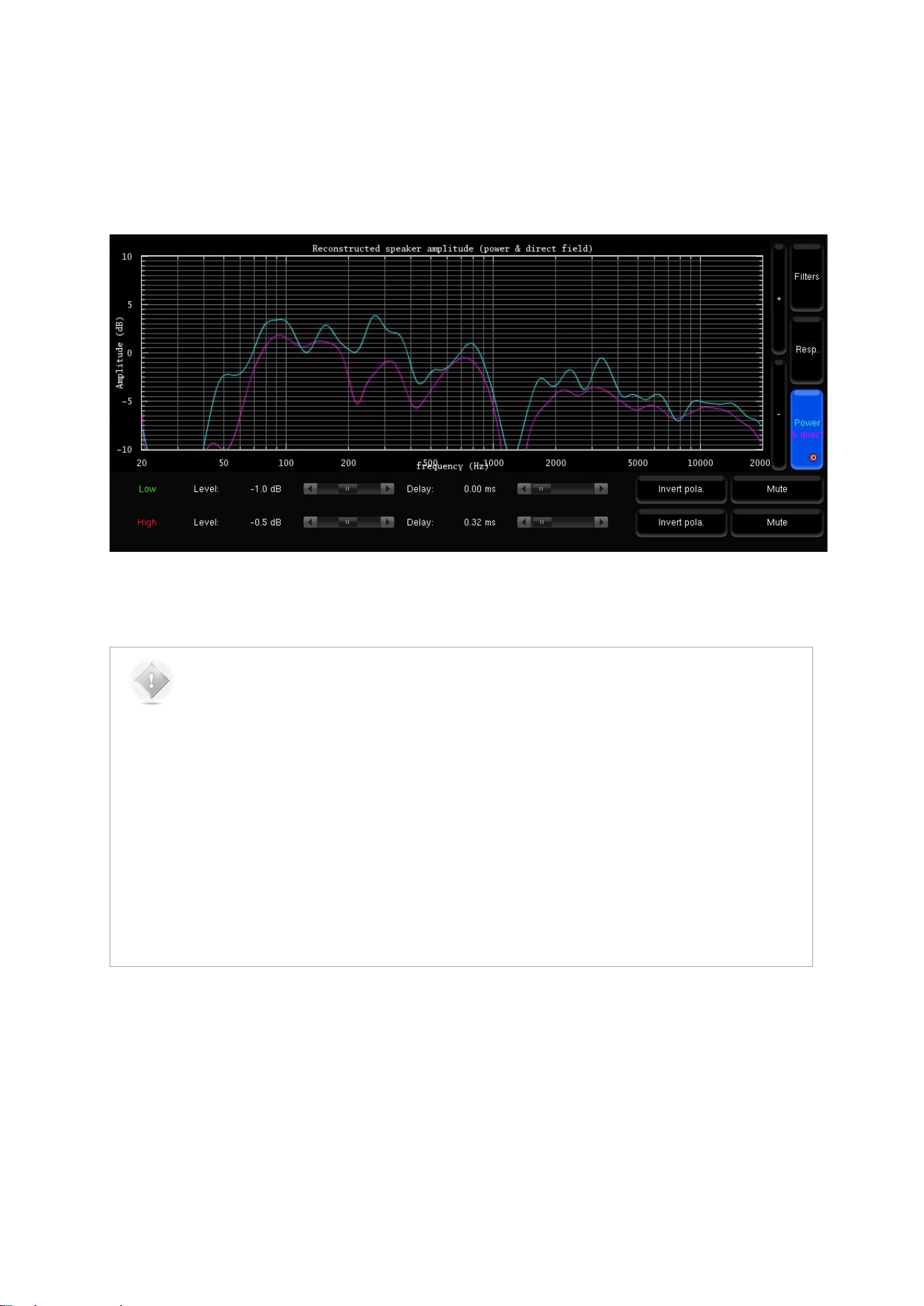
116
• The recombined amplitude response of the speaker: You can see whether the combination of the drivers is
constructive, and you can observe the effects of level/delay/polarity modification on the combined amplitude
of the speaker. Two curves are displayed, one showing the total acoustic output of the speaker (including the
room), and one showing the amplitude of the direct front and early reflections. Comparing both curves will
indicate whether the crossover preserves the directivity of the speaker: The two curves will look more alike
when the acoustic summation is optimized for the primary listening position.
Figure'83:'Recombined'amplitude'response'of'the'speaker'
NOTE:
• The levels, delays and polarities set previously are ignored during the calibration. In other words,
adjusting these parameters before launching the calibration will have no effect on the result.
• Under some circumstances, the automatic crossover algorithm may suggest inverted polarities
for a driver from one speaker to another. This can be explained by various factors:
• The physical polarity of one speaker is, indeed, inverted (from a cabling issue, as an
example). In this case, the correction suggested by the System should be applied to
improve audio quality
• Two adjacent drivers (for instance Mid and High) are phase-shifted by an amount of about
90°. In this case, the System provides more uncertain results, as it gets harder to see
whether the drivers are in or out of phase. If you are not comfortable with the results
provided by the System, you can correct them manually afterwards (via the button “Invert
polarity”).

117
LISTEN TO EACH SPEAKER CONNECTED TO THE
CROSSOVER
Listen carefully to each speaker connected to the crossover. You can play pink noise from the SDP-75 and/or play your
favorite music/cinema samples.
12.6 SAVE THE PRESET
Last but not least, don’t forget to save the preset to avoid losing the crossover settings.
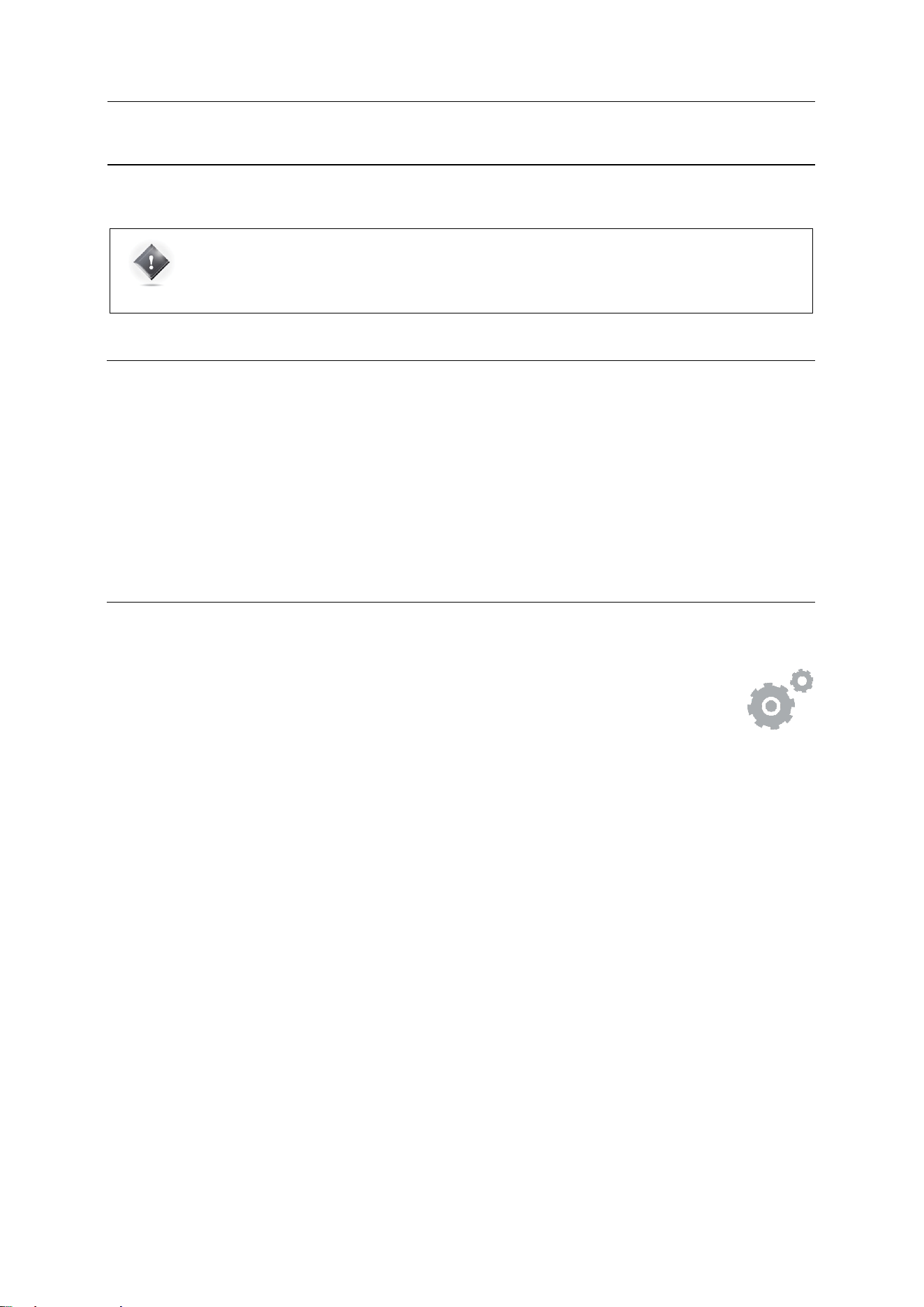
118
13 OPTIMIZER CALIBRATION
IMPORTANT NOTE: In order to perform a proper calibration it is important to carefully read the entire
chapters including Essential Tools and Settings and Getting Ready for Calibration to learn about the
SDP-75 audio clock settings, audio utilities (metering tools, pink noise and solo/mute buttons) and
microphone placement recommendations.
13.1 OVERVIEW OF THE CALIBRATION
PROCEDURE
If your speakers have been specified correctly, the calibration process is a relatively straightforward process:
1. Adjust the master output level to achieve high quality measurements;
2. Start the automated calibration: The SDP-75 will measure each loudspeaker in the room;
3. Compute the measurements;
4. Save the preset.
13.2 ADJUST THE MASTER OUTPUT LEVEL
To access the calibration page from the SDP-75 Main page:
• Click on the Gears button in the top menu to open the Advanced Settings user interface
.
• Go to the Level and Delay Settings/Calibration page.
The system requires a minimum Sound Pressure Level for proper calibration. Until that minimum SPL is reached, the
test signal will keep playing through the same speaker. For safety matters, we recommend to perform that first
calibration as if it were a test.
• Set a safe output level:
1. Decrease Master Level to -40 dB;
2. Press the Mute button to cut the outputs (this step must ALWAYS be performed before pressing
on the Calibrate button);
3. Press the Calibrate button in the Calibration tab in the Optimizer Settings page of the Adva
nced
Settings interface;
4. Follow the on-screen instructions regarding the microphone.
• Adjust the output level:
1. Increase the master level until the test signal moves on to the second speaker;
2. Use the SDP-75’s metering tools in the Processor/Meters page to check the level of t
he
microphone inputs;
3. Use your ears to evaluate the perceived SPL of each driver and, if possible, increase the master
output level to ensure that an optimal SPL is reached for all the speakers. This will also improv
e
the quality of your measurements;
4. Use the Cancel button to stop the calibration (optional).
During this process you will need to move back and forth between the calibration page and the metering page:
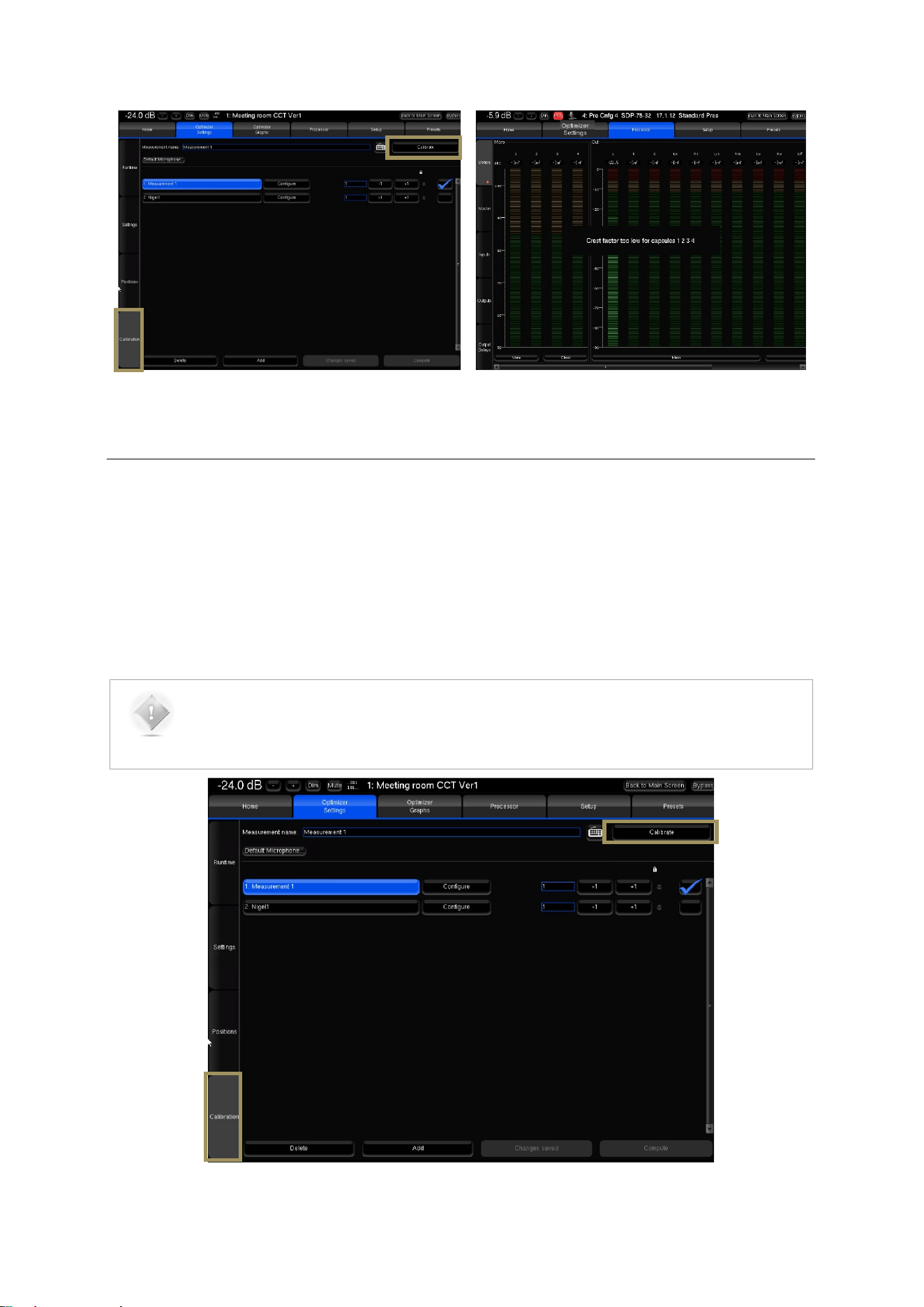
119
Figure'84:'Calibration'page'
Figure'85:'Metering'page'
13.3 NORMAL CALIBRATION SEQUENCE
Remain in the Optimizer Settings/Calibration page of the Advanced Settings interface to perform the final calibration:
• Follow the microphone placement instructions (see previous chapter);
• Make sure the measurement environment is silent;
• Press the Mute button to cut the outputs (this step must ALWAYS be performed before pressing the Calibrate
button);
• Press the Calibrate button in the top right corner of the page;
• Follow the on-screen instructions regarding the microphone.
NOTES:
• The calibration tool plays three bursts for every speakers and subwoofer;
• The calibration page indicates which speaker is being calibrated.
Figure'86:'The'calibration'page'

120
13.4 COMMON PROBLEMS DURING
CALIBRATION
If the calibration tool plays more than 3 MLS bursts for a speaker, it means that it’s finding it difficult to perform a
reliable measurement of that speaker.
The most common warning messages are explained below:
• “Crest factor too low for capsules”:
o Check the Input Meters in the Processor/Meters page.
o If the Input level is null on at least one of the 4 channels, go back to the Optimizer Settings/Calibration
page and stop the calibration.
o Check that the selected analog physical input is selected in the Home/Select page.
o Make sure the microphone routing is correct.
o The microphone battery may be low. The red led at the front of the microphone indicates the battery
level.
o The microphone or cable could be damaged.
• “Unstable position for speaker”:
o Someone may have moved during the calibration.
o Too many strong reflections around the microphone environment could be disturbing the impulse
response measurement.
o An obstacle between the microphone and any of the speakers can disturb the measurement.
o The bandwidth of one of the speakers may be too narrow.
• “Unable to localize speaker” :
o Dipole/bipole speakers provide more than one wave at the same time, which can cause issues.
o Several speakers may be chained, providing more than one wave at the same time.
13.5 CALIBRATION STATUS
The calibration status has 3 possible values:
• Yes : If no problem occurred during the measurement. After calibration, the Top Bar indicates NOT READY,
which means no sound can go through the processor until the optimization filters are computed.
• Partial : If the calibration was stopped in the middle of the measurement process.
• No! : When no measurement has not been performed.
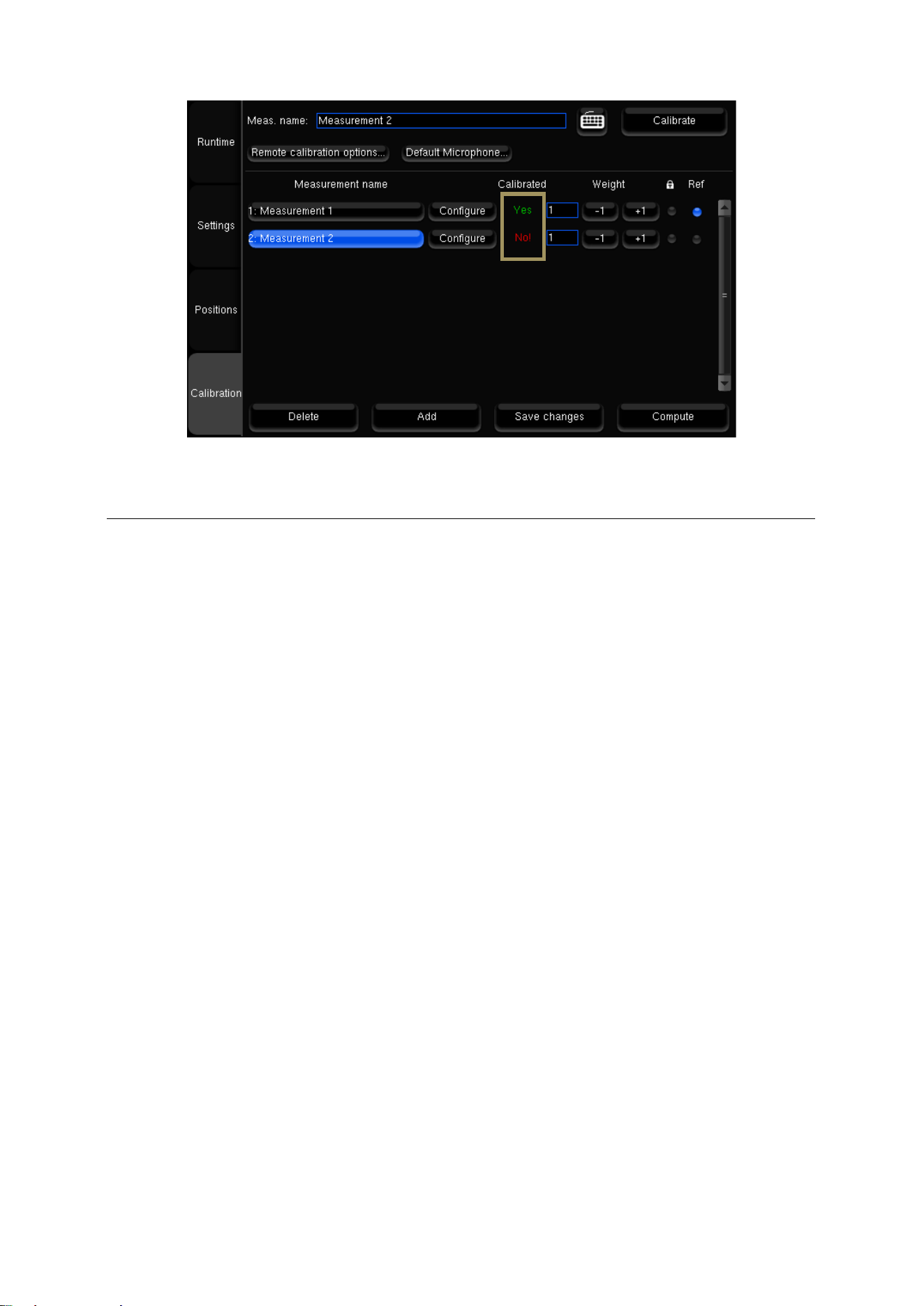
121
Figure'87:'Calibration'status'
13.6 CHECKING THE SPEAKER SUMMARY AFTER
CALIBRATION
The Optimizer Settings/Positions page displays the measured speaker locations in real-time during calibration.
Three views are provided:
• Top view: The speakers are seen from above;
• Elevation view: The speakers are seen from the listening point. Relative degrees of elevation and azimuth are
displayed;
• Details view: A table listing the measured distance, elevation, azimuth, level, delay etc.
By default, the Optimizer page always displays the reference speaker positions in green. These positions are specified in
the template of the initial speaker layout (2.0, 5.1, 7.1, Atmos, Auro-3D, DTS).
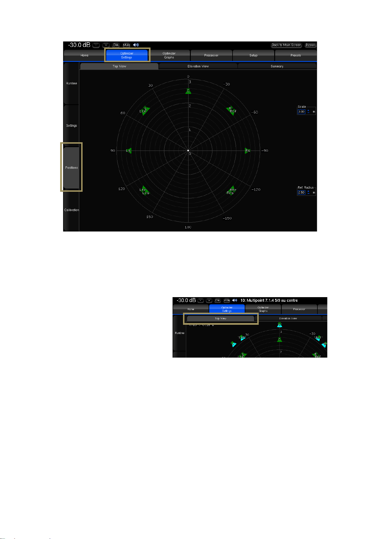
122
Figure'88:'Top'view'of'a'7.1.4'layout'before'calibration'
As the calibration is performed, the real position of each speaker is displayed after the 3
rd
MLS burst.
The Top View helps to identify wrong speaker
placements. It might be necessary to
recalibrate if the microphone is not perfectly
pointed towards the center of the front stage,
but that would only impact the visual
representation.
Figure'89:'top'view'of'a'7 .1 .4 'a fte r'c a lib ra tio n '
This view also provides the RT60 on the top left corner of the page.
• Overlay both representations with the Scale and Ref. Radius options to verify the compliance with the
recommended placements.
• The channel name displayed on each speaker is related to the channel order defined in the Speakers/Room setup
tool.
• The color of the loudspeakers depends on the Remapping settings.
• The Elevation View uses the same color codes to display the real speaker positions. It indicates whether the
microphone was or was not correctly leveled during the calibration:
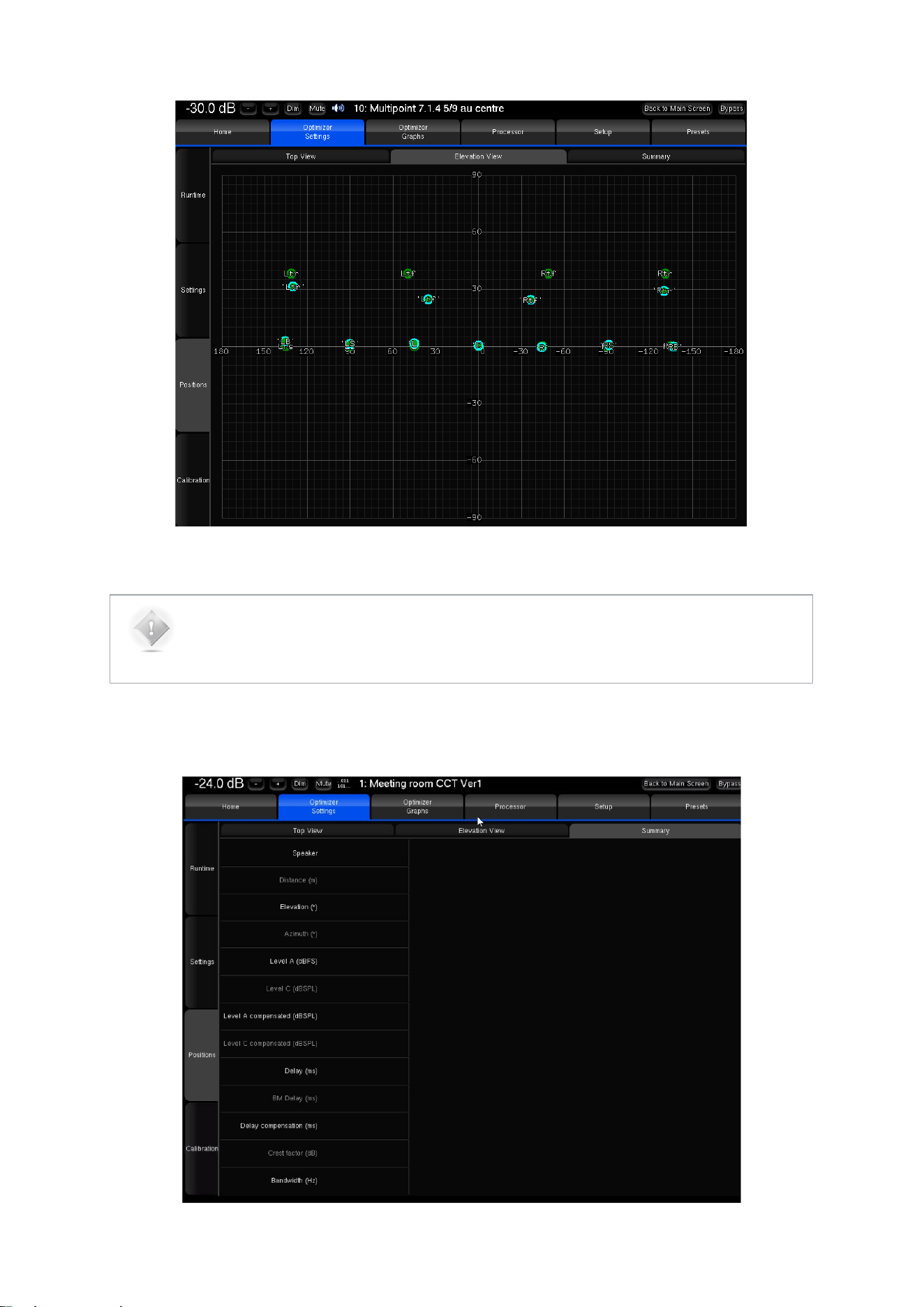
123
Figure'90:'Elevation'view'of'a'7.1.4'system'after'calibration'
NOTE:
• If one speaker cannot be located during calibration, it will be displayed in the center of the circle.
The Summary page provides additional measurements for each speaker:
Figure'91:'Speaker'measurements'summary'

124
Measurement details:
• Distance is the distance of the speaker (in meters) to the measurement point;
• Elevation is the elevation of the speaker (in degrees) to the measurement point;
• Azimuth is the azimuth of the speaker (in degrees) to the measurement point;
• Level A corresponds to the A-weighted level of the speaker;
• Level C corresponds to the C-weighted level of the speaker;
• Delay corresponds to the distance of the speaker;
• Bandwidth corresponds to the measured bandwidth of the speaker;
Correction details:
• Level A Compensated corresponds to the A-weighted compensated level of the speaker;
• Level C Compensated corresponds to the C-weighted compensated level of the speaker;
• Delay Compensation is the delay that is added to every speaker to time align the system;
• BM Delay may be added to the subwoofer to improve the crossover with the satellites. More rarely, if the
subwoofer is in advance, all the satellites are delayed;
• Polarity specifies whether the system will invert the polarity of the speaker. Please note this is not the
“measured polarity” of the speaker;
• Crest Factor helps evaluating the quality of the measurement. It should be higher than 30dB. Low values could
indicate background noise problems;
13.7 MULTI-POINT MEASUREMENTS (OPTIONAL)
For multipoint measurements, please see the chapter about performing multi-point measurements later in this manual.
13.8 COMPUTE THE OPTIMIZATION FILTERS
After the calibration is successfully completed, the Top Bar indicates NOT READY, which means no sound can go
through the processor until the optimization filters are computed.
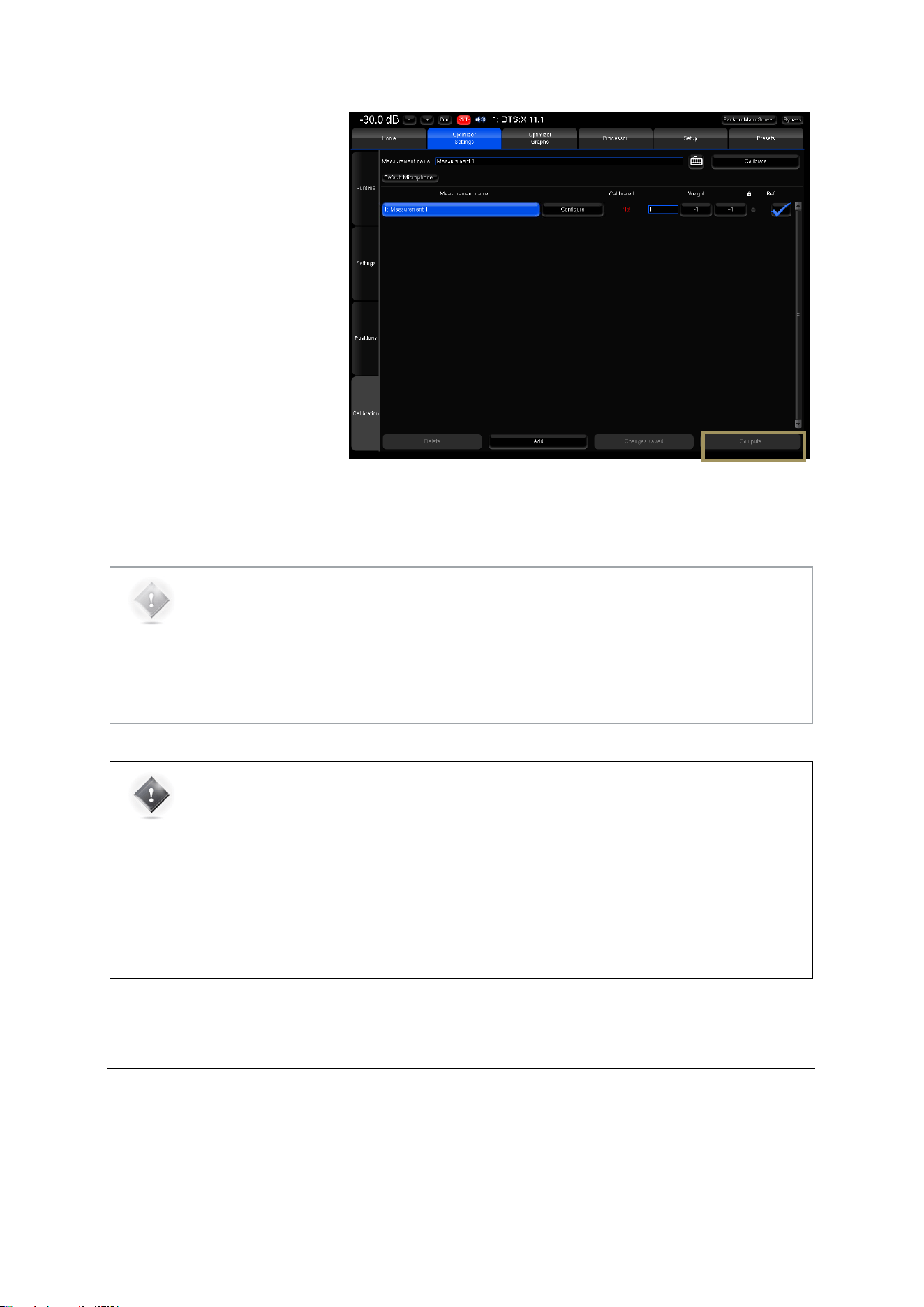
125
To compute the optimization filters
for your speaker measurements:
• Go to the Optimizer
Settings/Calibration page;
• Press the Compute button to
start the calculation of the
compensation filters. This will
also create the Optimizer
graphs.
Figure'92:'Computing'the'optimization'filters'after'calibration!
NOTE:
• The top bar will display a gear wheel icon and a graph icon during computation.
• An onscreen message notifies the end of the computation.
• The speaker icon indicates that the Optimizer is ready.
• Computation time varies depending on the number of speakers in the system and on the
Optimizer parameters.
IMPORTANT NOTE:
• Once the speaker system has been calibrated, all changes will be applied by recalculating the
filters by pressing the Compute button.
• Performing new measurements is not required unless:
• Speakers/Furniture/listening positions change in the room;
• the active crossover filters are modified;
• The number of speakers is modified;
• The channel order is modified.
13.9 SAVE THE PRESET
Last but not least, be sure to save the preset to make sure all your preferred measurements and computed filters are not
lost.
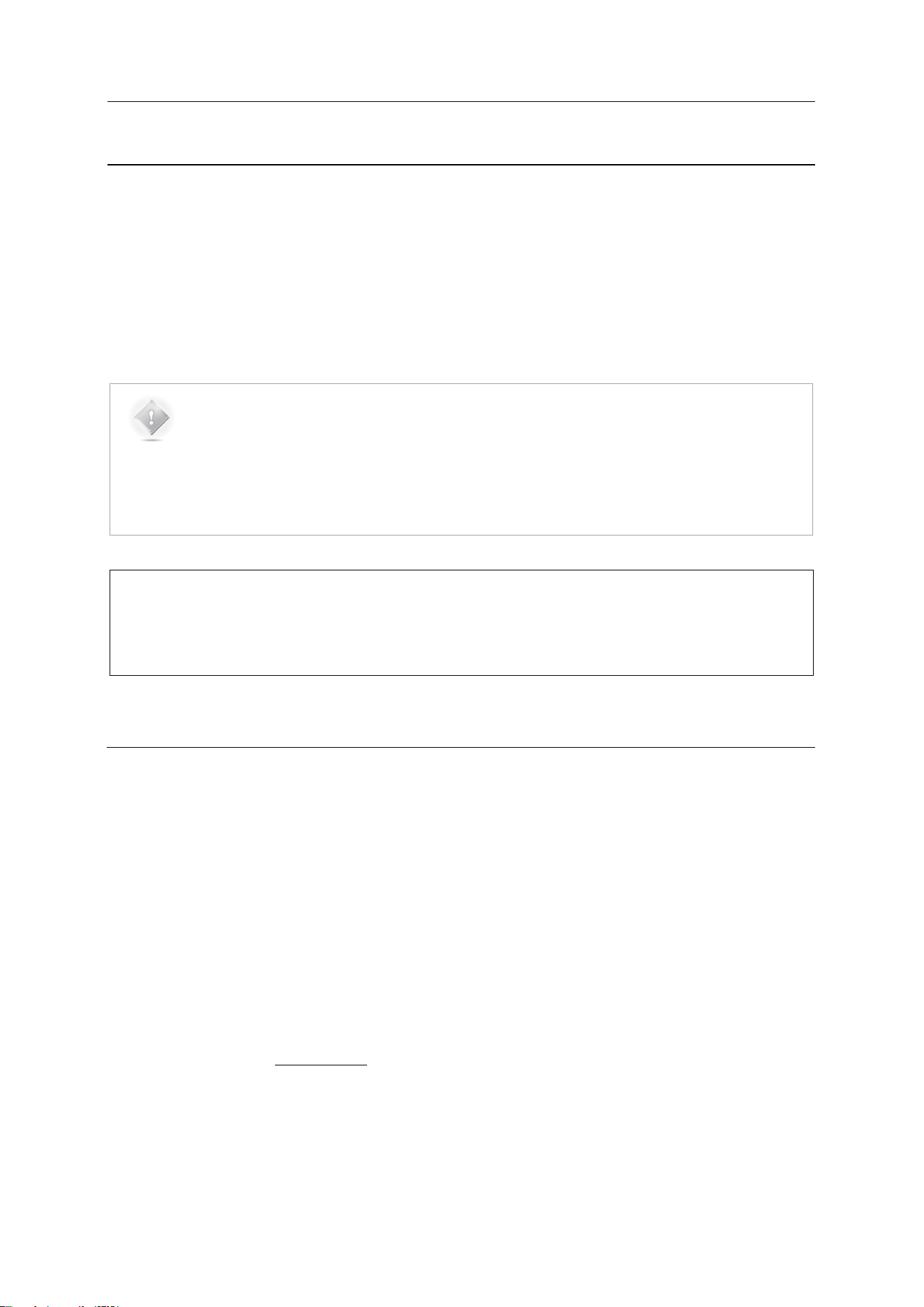
126
14 SETUP BASS MANAGEMENT
This chapter explains how to setup bass management in the SDP-75.
The SDP-75 provides very flexible options that help you to optimally configure the bass management
of your system. You can specify how the lower frequencies of each channel will be reproduced by one
or more subwoofers.
In other words, individual speakers can be bass-managed with any combination of subwoofers and
specific crossover frequencies.
NOTE:
• The SDP-75 supports any number of subwoofers as long as enough physical outputs and
processing channels are available, therefore allowing for a maximum flexibility in the speaker
system design.
• Bass Management can be activated even if the system has not been calibrated. However, the
automatic time-alignment of the subwoofers is only performed after a calibration of the whole
set of speakers
IMPORTANT NOTE:
• For optimal results, the bass management should be setup manually based on the acoustic measurements
of the speaker responses in the room.
• The Bass Management results do not impact the Optimizer graphs.
14.1 OVERVIEW OF THE BASS MANAGEMENT
SETUP PROCEDURE
The recommended bass management setup procedure is as follows:
• Analyze the acoustical graphs of the speaker measurements in order to understand the low frequency response
of each speaker in the room;
• Decide whether bass management is necessary or not. It is always necessary when using one or more
subwoofers.
• To activate bass management:
1. Identify the High Pass Frequency that seems appropriate for each channel. 80 Hz is usually the best
choice.
2. Configure the bass management options (Off, On, On + Lfe to lr);
3. Configure each channel to be bass-managed by one or more subwoofers.
• Last but not least: Save the preset.
The Bass management is divided into 3 different sections represented as 3 tabs which will be detailed in the following
chapter:
• Quick Setup: The Quick Setup is the default section of the Bass Management. It allows a global configuration by
applying values on several speakers and subwoofers simultaneously (It is not enabled if Bass-Management is Off);
• Individual Setup: The Individual Setup provides the ability to adjust the settings on each speaker and sub
individually (It is not enabled if Bass-Management is Off);
• LFE & Misc: This section allows adjustment of the LFE gain, polarity, Low-pass filter type, Low-pass frequency,
slope, as well as enabling the standard +10dB LFE input and stacked sub correction.
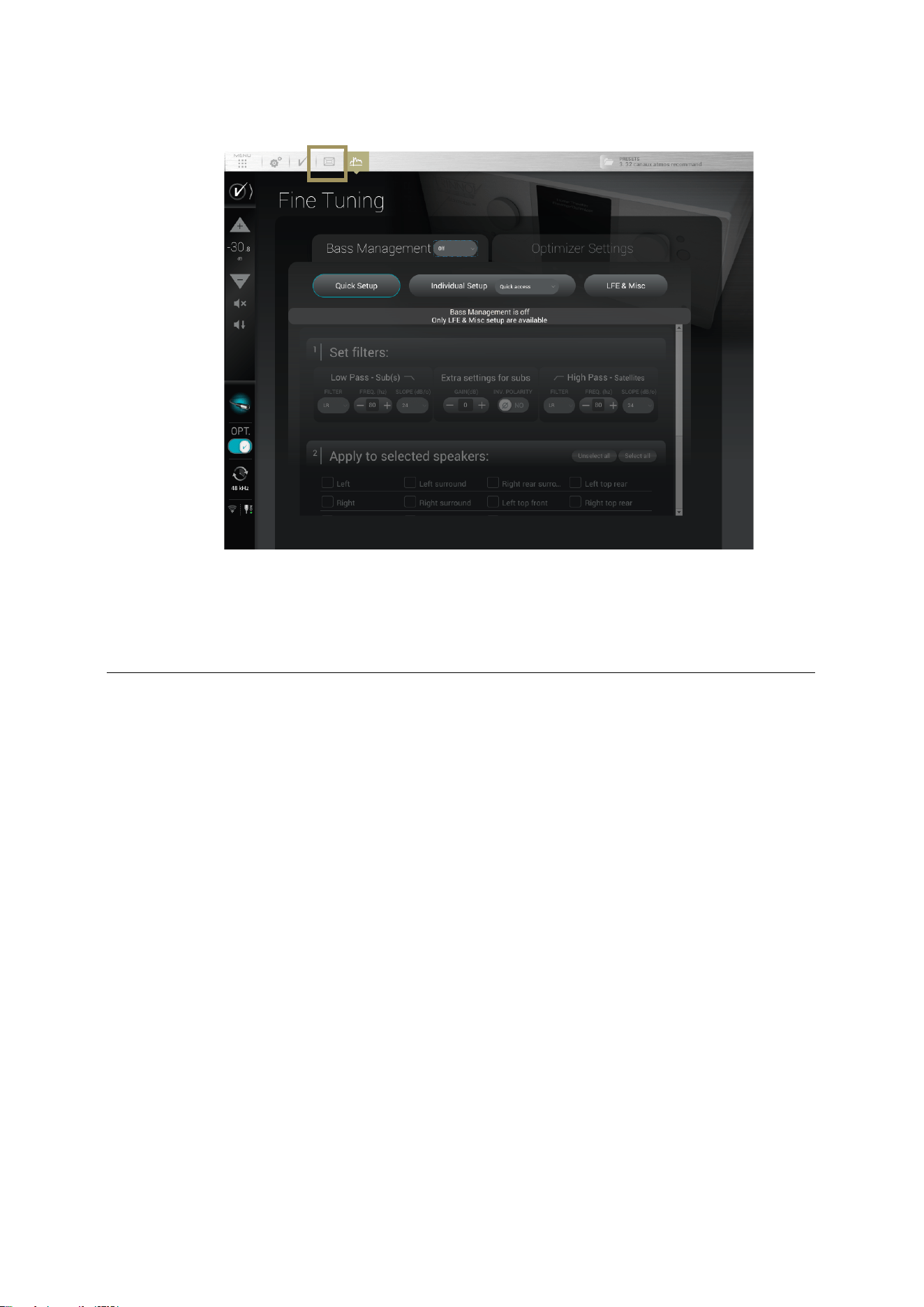
127
The Bass Management page is accessible through the Top Menu of the SDP-75 User Interface:
Figure'93:'Access'to'the'B a ss 'Management'options'
•
•
14.2 FULLY CUSTOMIZABLE BASS MANAGEMENT
The SDP-75 allows you to specify how the lower frequencies of each channel will be reproduced by one or more
subwoofers. For every speaker you can:
• Specify a High Pass Frequency;
• Activate one or more subwoofers that will reproduce the lower frequencies from that channel;
• Setup the gain for each subwoofer;
• Invert the polarity for each subwoofer.
This is different from the majority of the currently available AV surround preamplifiers which offer relatively simple bass
management features. They usually allow you to choose from only two types of speakers: “large” or “small”, and have
predefined parameters for the bass management filters.
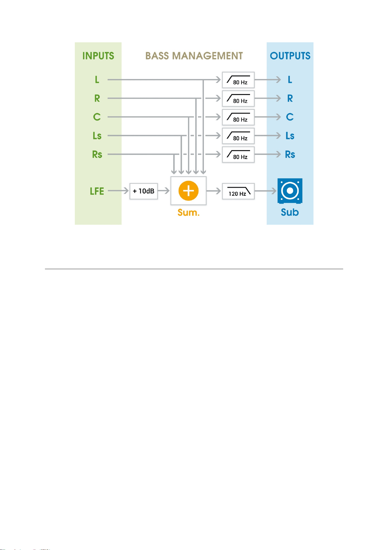
128
Figure'94:'Typical'bass'management'in'a'standard'surround'preamplifier'
14.3 BASS MANAGEMENT MODE
The SDP-75 offers 3 different bass management modes:
• Off: No bass management (default)
• On: Standard bass management mode, which is recommended for all installations utilizing subwoofers.
• On + LFE to LR: Distributes the LFE signal to the Left and Right speakers. Can be used when there is no subwoofer
in the system. Note that in this mode, if a subwoofer is declared, the LFE will not be played by this subwoofer. This
mode is rarely recommended.
Those modes are accessible from dropdown menu as shown below:
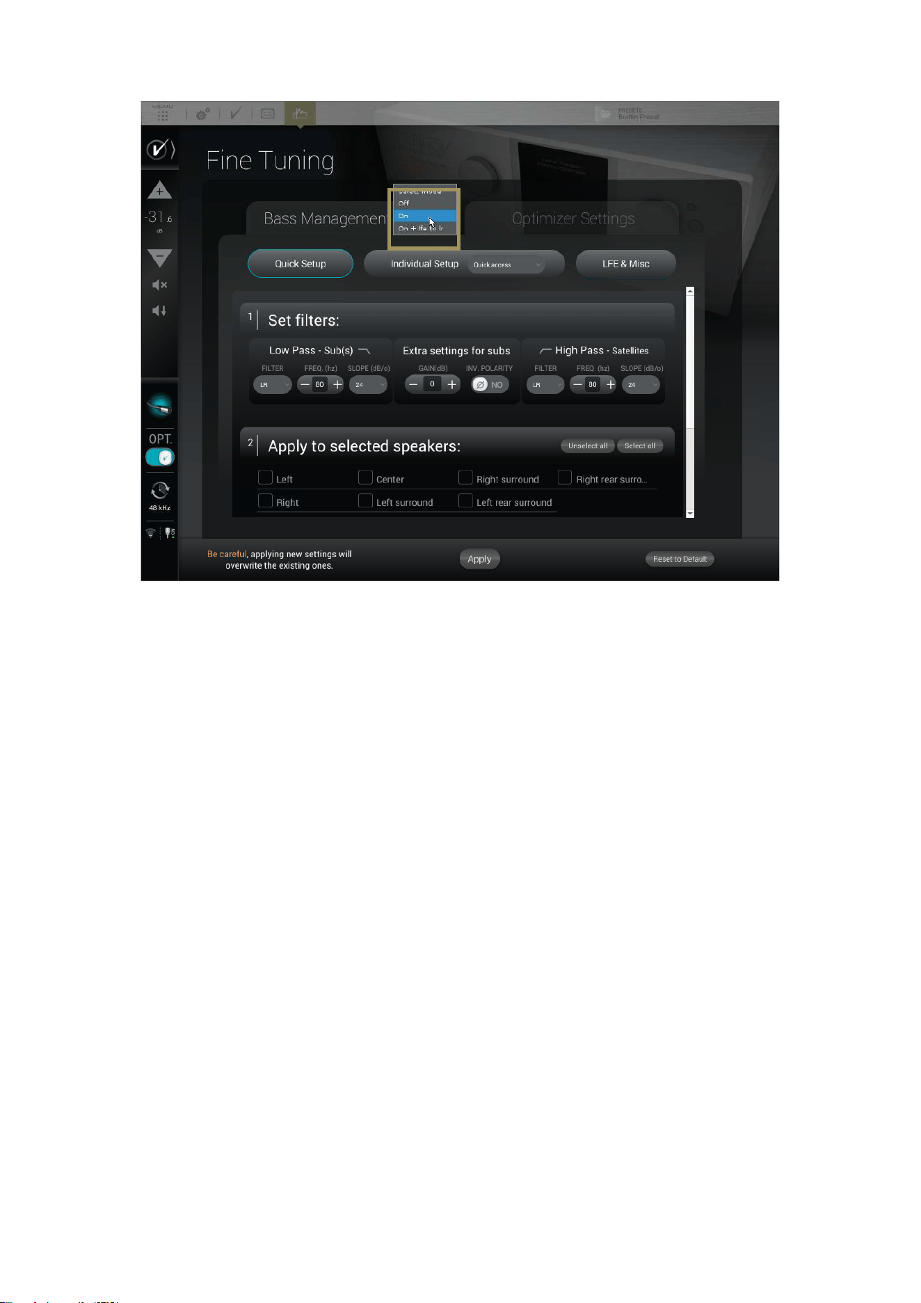
129
Figure'95:'Access'to'the'B a ss - Management'options'
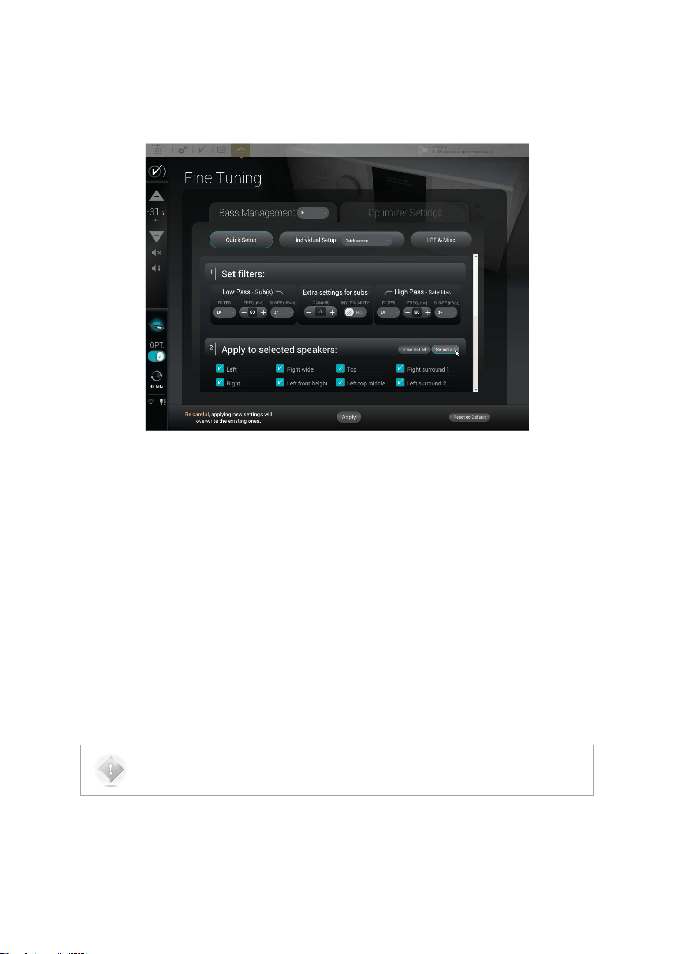
130
14.4 QUICK SETUP MENU
The Quick Setup menu is a powerful tool allowing to configure the bass management for several speakers all at once.
Figure'96:'Bass'Management'Quick'Setup'
'
The Quick Setup menu is divided into 3 main section:
1. Set Filters: This section is to specify the filter type and frequency that will be applied;
2. Apply to selected speakers: Here, you can select the speakers on which you can apply the filters selected in the
first section;
3. And apply to associated sub(s): Select the sub(s) associated to the group of speakers and filters.
The 3 sections are detailed in the sub-chapters below.
The configuration steps are the followings:
• Enter the desired settings in the 1| Set filters table;
• Select the speakers on which you want to apply thoses settings on the 2| Apply to selected speakers section;
• Select the associated sub(s) in the And apply to associated sub(s) section;
• Press on the Apply button to validate;
• Do the same for another group of speakers and sub if needed;
• Listen and adjust if needed;
• Save the preset.
NOTE: It is not possible to apply the settings if no subs are selected. This means that you cannot
disable bass management on several speakers at the same time with the Quick Setup menu. To do so,
please use the Individual Setup described in the next sub-chapter.
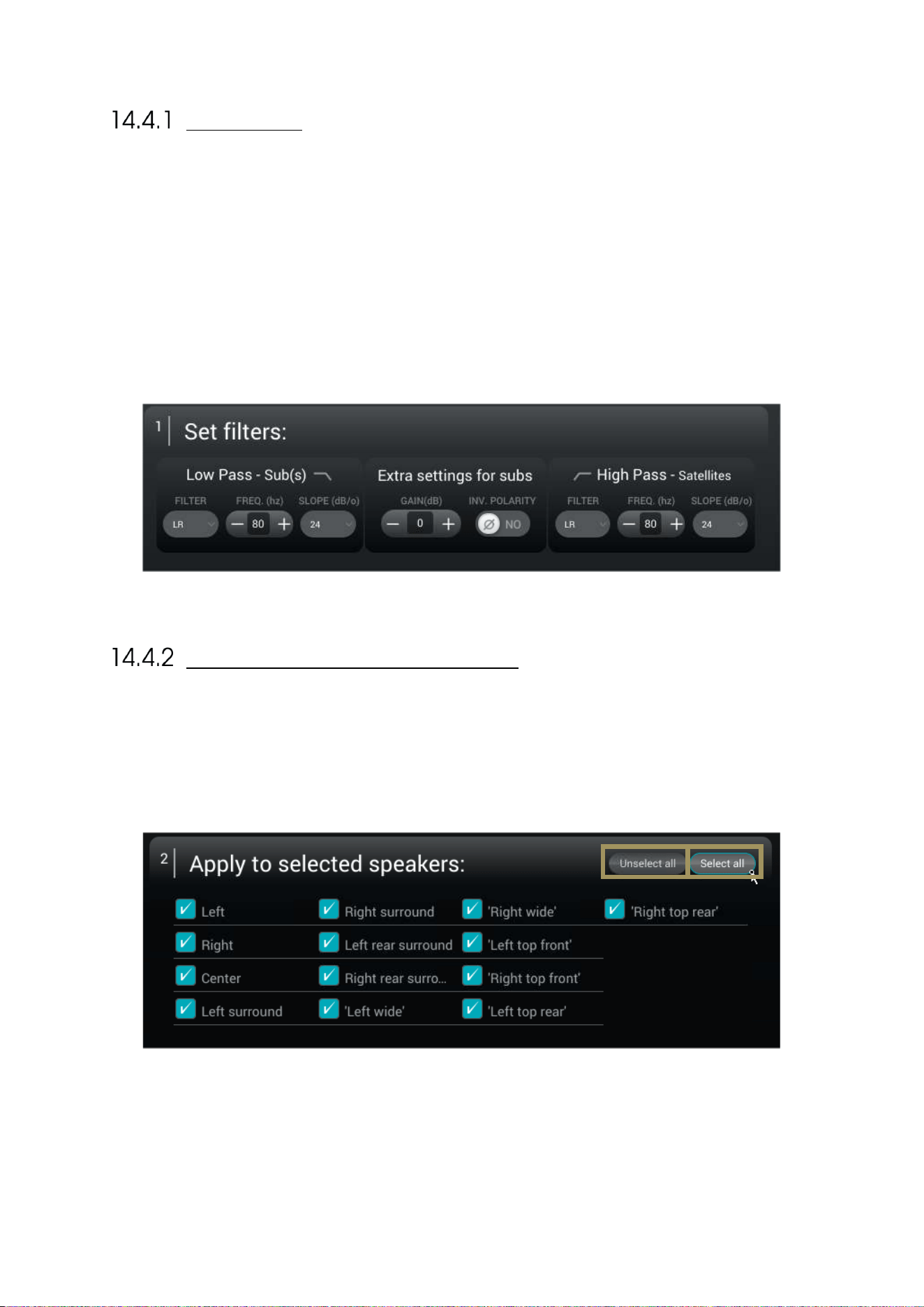
131
SET FILTERS
As shown below, this first section is divided in 3 different groups of settings:
• Low Pass – Sub(s) : These settings will define the cutoff frequency under which the signal from the channel will
be redirected and played by the subwoofer(s). You can select the type of filter (Linkwitz-Riley, Bessel or
Butterworth), the cutoff frequency and the slope used by this filter. These settings only apply to the signal
redirected to the subwoofer(s).
• Extra settings for sub(s): These additionnal settings give the possibility to invert the polarity and adjust the gain of
the signal that is redirected to the subwoofer(s). These settings only apply to the signal redirected to the
subwoofer(s).
• High Pass – Satellites: This section will define the low-end cutoff frequency of the signal send to the satellites.
You can here select the type of filter (Linkwitz-Riley, Bessel or Butterworth), the cutoff frequency and the slope use
by this filter. These settings are apply to the signal redirected to the Satellites. 80 Hz, with a 24 dB or greater slope
is generally advised, unless some of the satellites could be damaged if extended to 80Hz. In such cases, Individual
Setup should be used.
APPLY TO SELECTED SPEAKERS
The second section is here to define the group of speakers on which the filters will be applied. The speakers, or satellites,
are only affected by the High Pass filter. The speaker selection is done by checking the box on the left side of each
speaker’s name.
Two buttons are in the Top right corner of this second section:
• Unselect all: Clicking on this button unselects every speaker;
• Select all: Clicking on this speaker selects every speaker.
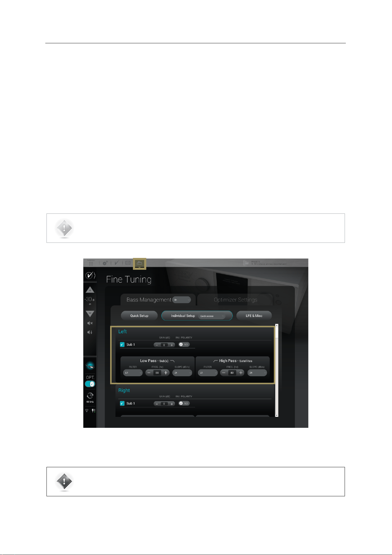
132
14.5 BASS MANAGEMENT SETTINGS FOR
INDIVIDUAL SPEAKERS
The settings provided are similar to the Quick Setup menu but are adjustable on each speaker individually. Each speaker
has the following parameters:
• The activation of each sub by checking the Active box (which recalculates the attenuation accordingly): The bass-
managed signal will be redirected to the selected subwoofer(s);
• Gain and Polarity These additionnal settings provide the option to invert the polarity and adjust the gain of the
signal redirected to the subwoofer(s). These settings are only applied to the signal redirected to the subwoofer(s),
the signal going to the speaker remains unchanged;
• Low Pass – Sub(s) : These settings will define the cutoff frequency below which the signal from the channel will
be redirected and played by the subwoofer(s). You can select the type of filter (Linkwitz-Riley, Bessel or
Butterworth), the cutoff frequency and the slope used by this filter. These settings are only apply to the signal
redirected to the subwoofer(s);
• High Pass – Satellites: This section will define the low-end cutoff frequency of the signal sent to the satellites. You
can select the type of filter (Linkwitz-Riley, Bessel or Butterworth), the cutoff frequency and the slope use by this
filter. These settings are only apply to the signal redirected to the Satellites.
NOTE: Bass Management mode must be set to On in order for these settings to be taken into account.
Figure'97:'Configuring'the'bass'management'settings'for'every'speaker'
IMPORTANT NOTE: If there is no active sub for one or more satellite, the high-pass frequency is still
active. If a full-range speaker is needed, set the High-Pass filter type to None and it will disable the
filter.
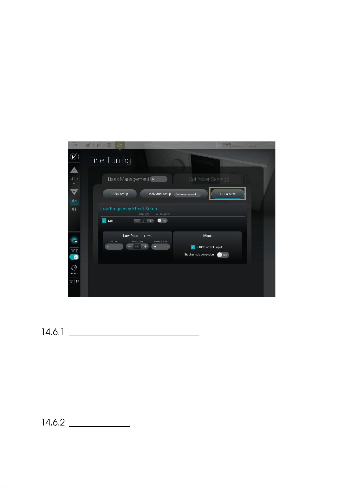
133
14.6 LFE & MISC
The LFE & Misc Setup page is active even if the Bass Management is Off. These parameters only impact the
subwoofer(s).
LFE stands for “Low Frequency Effects,” and is an optional channel that may or may not be present in source material,
and which is the “x.1” channel. LFE signals should always be reproduced by subwoofer(s).
The page is divided as followed:
• A table allowing the assignment of the LFE channel of the content, if present, to one or more subwoofer(s)
• A Low Pass – LFE section to set a filter on the LFE channel
• A Misc. section with various options
Figure'98:'LFE'&'Misc'p a ge '
LOW FREQUENCY EFFECT SETUP
This first section is here to choose which subwoofer is assigned to the LFE channel. A subwoofer assigned to the LFE
will play the .1 of the content.
To assign the LFE channel to a subwoofer, please tick the box of the desired subwoofer.
The LFE signal can be filtered. A Low Pass filter is available and only apply on the LFE channel (not on the subwoofer(s)
assigned).
Low Pass – LFE: This setting will define the cutoff frequency of the LFE channel. You can select the type of filter (Linkwitz-
Riley, Bessel or Butterworth), the cutoff frequency and the slope used by this filter.
+10 DB ON LFE
Unless the encoded bitstream signal is decoded upstream by another device, the +10dB on LFE input option should be
enabled (default). It applies a gain of 10dB on the incoming LFE signal. The default is almost always the correct setting.
134
STACKED SUB CORRECTION
The Stacked subs option is designed for stacked multiple-subwoofers configurations.
When multiple subwoofers are used to reproduce the same signal, the perceived level increases. The SDP-75
automatically decreases the signal sent to each subwoofer to maintain the same perceived level depending on the
number of subwoofers used to reproduce the same signal. The attenuation varies, depending upon whether the
subwoofers are located very close to each other, or are located well-away from each other, which is typically the case.
In such multiple subwoofers configurations, two typical cases are handled by the SDP-75:
• If subwoofers are considered as decorrelated (away from each other), their power add up.
• If subwoofers are considered as correlated (positioned next to each other or stacked), their amplitude add up.
Therefore, whether the stacked subs option is disabled (default) or enabled, an automatic attenuation of the signals will
be calculated accordingly to maintain a consistent level.
Number of subwoofers in
the system
Attenuation if “Stacked
subs” disabled
Attenuation if “Stacked
subs” enabled
2 subwoofers
-3 dB
-6 dB
3 subwoofers
-4.8 dB
-9.5 dB
4 subwoofers
-6 dB
-12 dB
Figure'99:'Level'of'attenuation'and'the'Stacked'Subs'option'

135
15 SETUP TARGET CURVES
The SDP-75 implements Target Curves as a powerful tool for achieving the required
frequency response from your system. For every speaker in the room, a target curve
can be defined in terms of:
Amplitude only / Amplitude and Phase / Amplitude and Group Delay
One or more channels can be linked in order to share the same target curve for several speakers.
15.1 OVERVIEW OF THIS PROCEDURE
In the SDP-75, setting target curves is a very straightforward procedure:
• Decide if you want to apply the same target curve to all the speakers (except subwoofers), or if you want to
apply a different target curve depending on the type of speaker.
• Link/unlink the speakers that will share the same target curve.
• Setup the target curve for each group of speakers.
• Press the Apply Change button.
15.2 SETTING UP ONE OR MORE TARGET CURVES
To edit the target curve for one or more speakers, go to the Optimizer Settings/Target Curve page in the Advanced
Settings user interface:
The most usual case is to link all the speakers except the subwoofer(s). Therefore, by default, the Link button is activated
for all the speakers except for the subwoofer(s). If this is not the case, you can press the Link all but Sub button.
Use the arrow keys of your keyboard or you mouse to edit the target curve:
• The green dots correspond to the required values for each frequency,
• The yellow line displays the expected result, taking into account the behavior of the filter.
Press the Apply Changes button. This button becomes orange as soon as you change some setting that requires a new
computation of the optimization filters.
Save as a new preset. This will allow you to compare the sound with and without the target curve.
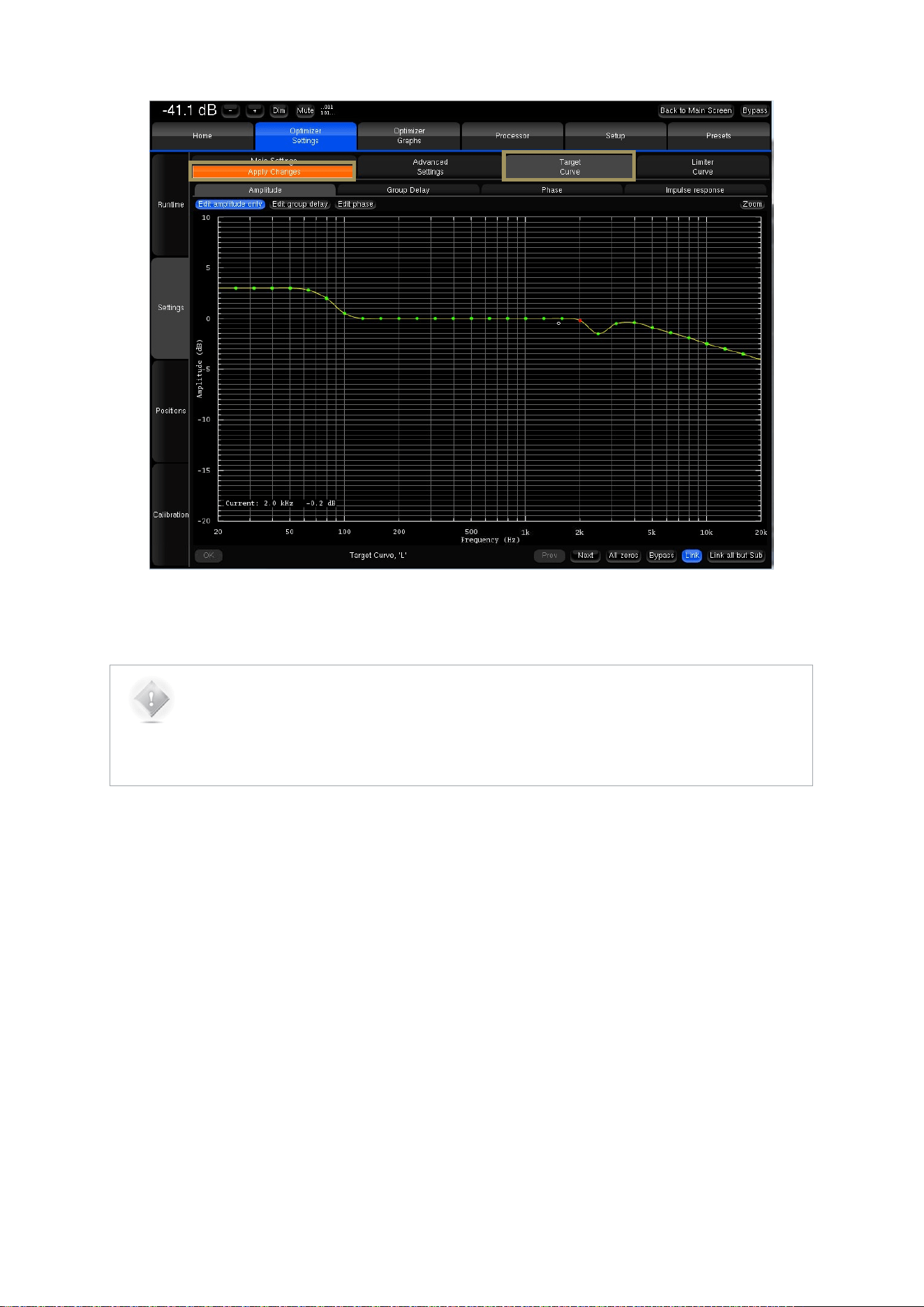
136
Figure'100:'Example'of'a'Target'Curve'in'the'Advanced'Settings'user'interface'
NOTE:
• By default, the Optimizer will use both IIR and FIR filters to achieve the target curve.
• In addition to target curves, several other parameters define the behavior of the automatic
equalization.
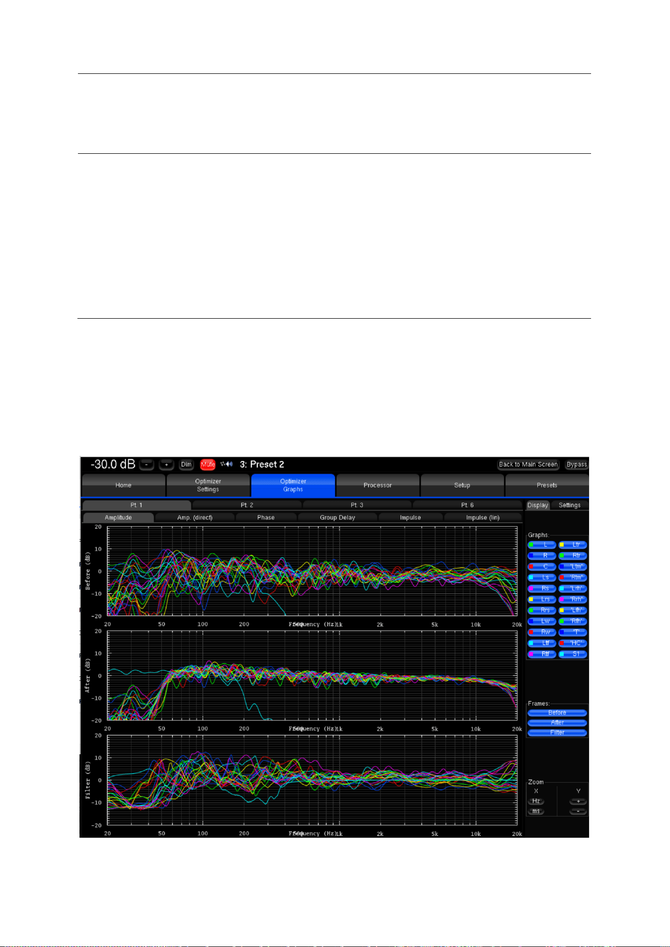
137
16 VERIFY THE SOUND OF YOUR
OPTIMIZED SPEAKER SYSTEM
Once you have completed all the steps of the system setup procedure, it is critically important to verify the sound of the
entire system. This should help you to identify any possible issues:
• Look at the acoustical graphs of all the speakers;
• Listen to the system.
After all possible issues have been corrected, you will be confident that the system is ready to deliver the best home
theatre experience available today.
16.1 VISUALIZE THE ACOUSTICAL GRAPHS FOR
ALL SPEAKERS
Go to the Optimizer Graphs page and visualize the acoustical graphs of one or more speakers.
Depending on your observations, you may decide to change the target curves, the bass management settings, or some
of the more advanced optimization settings. See the next chapter for a detailed explanation of the comprehensive fine
tuning options offered by the SDP-75.
Figure'101:'Visualizing'the'a co u stical'graphs'for'the'whole'system '

138
16.2 LISTEN TO THE SYSTEM
Most importantly, listen carefully to your system by playing your favorite music and cinema samples. As an option, you
could also play pink noise from the SDP-75 to perform additional acoustical measurements with your own acoustical
measurements tools.
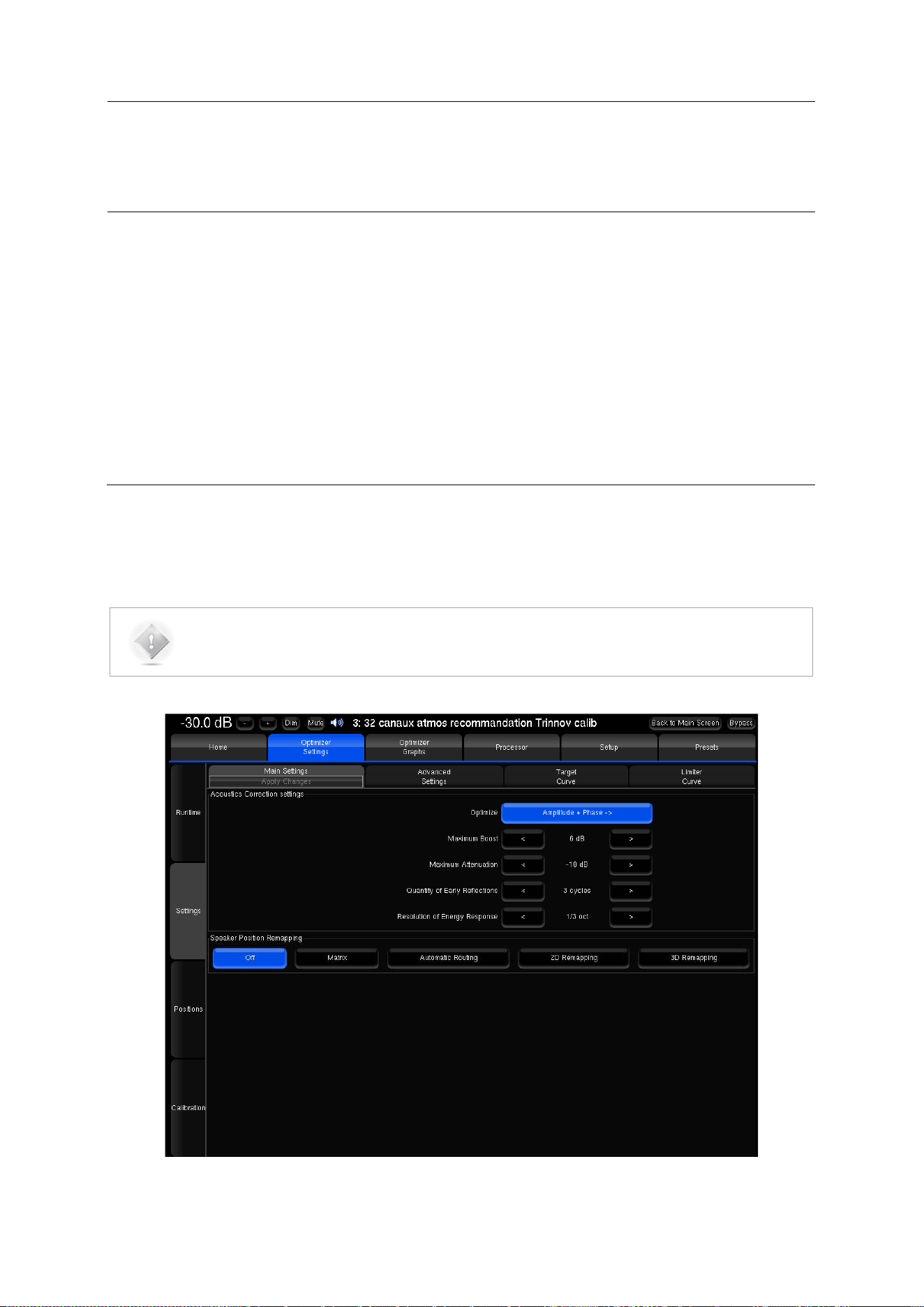
139
17 FINE TUNING OPTIMIZATION
SETTINGS
In order to tune the optimization settings you need to know the basics about the SDP-75’s audio tools and settings. You
will be using those tools throughout the tuning process for:
• Playing pink noise on the speakers
• Solo/mute inputs or outputs
• Switching optimization on/off
• Viewing the acoustical graphs.
For a detailed explanation of all those tools, please refer to the Essential Tools and Settings chapter.
17.1 MAIN OPTIMIZATION SETTINGS
The Optimizers Main Settings are located in the Optimizer Settings/Settings/Main Settings page.
NOTE: Changes made in the Optimizer Settings do not require new acoustic measurements. The new
compensation filters are recomputed on the fly using the Apply changes button.
Figure'102:'Main'optim iza tio n 's et tin g s'

140
• Optimize (Optimization Modes): The SDP-75 offers four different optimization modes with very specific behavior:
o Amplitude + Phase (default):With this setting, the Optimizer will improve both the loudspeaker amplitude
and the phase response of the loudspeaker. This greatly reduces the group delay of the speakers
starting from about 150Hz.
o Amplitude only: This mode tells the Optimizer to work only on the amplitude of the loudspeaker’s
response. The phase behavior is not modified;
o Low range only: With this setting the automatic equalization will only use IIR filters up to the frequency
defined in the advanced settings (Default: 150Hz). The automatic FIR filter is disabled, but manual FIR
EQ can still be applied;
o According to L&R speakers: This is a special mode that will optimize the other speakers in order to
achieve the same response as the averaged Left+Right speakers. The different options available for this
mode are explained in the Advanced Optimization Settings subchapter.
• Maximum Boost/Attenuation:
o Maximum boost: defines, in dB, the maximum amount of boost that will be performed by the algorithms.
This parameter is used to avoid distortion. Its default value is 6dB.
This parameter has an important impact on the behavior of the automatic equalization, and is applied
to both the time-based and the amplitude-based approach.
o Maximum attenuation: defines, in dB, the maximum amount of attenuation that will be performed by the
algorithms. Its default value is -10dB.
This parameter also has an important impact on the behavior of the automatic equalization, and is
applied to both the time-based and the amplitude-based approach.
See also the Limiter Curve functionality described below.
• Acoustic parameters “Quantity of Early Reflections” and “Resolution of Energy Response”:
The SDP-75 uses two different approaches for the Optimization of Loudspeaker/Room Acoustics:
1. A time-based approach for the correction of Early Reflections (ER). The main parameter that defines the
behavior of this algorithm is the width of the time-frequency window “Quantity of Early Reflections”.
• Quantity of Early Reflections (default is 3 cycles): A simple parameter that characterizes the quantity of early
reflections that the Optimizer tries to compensate is the width of the time-frequency window. The size of this
window is defined by a number of cycles, hence the naming “
a
/f”, where
a
(alpha) is the number of cycles and
f the frequency (1/f being one cycle).
• The meaning of the time-frequency window is as follows: for each frequency a different duration (or width of
the time window) is taken into account. At low frequencies the window typically starts at 150ms for 20Hz, and
decreases constantly to be as low as 0.3ms at 10 kHz.
•
2. An amplitude-based approach for the correction of Late Reverberation (LR), whose main parameter,
Resolution of Energy Response is the smoothing applied to the energy response.
• Resolution of Energy Response (default is 1/3 octave): It defines, in number of octaves, how the room’s energy
response is smoothed, and modifies the behavior of the equalization performed by the Optimizer on the Late
Reverberation. Its default value is 1/3 octave.
• The behavior of the energy optimization algorithm varies according to the smoothing applied to the room
response. If the response is less smoothed, sharp peaks in the response will be more taken into account for
the correction, while with more smoothing only the overall tonal balance of the room will be corrected.
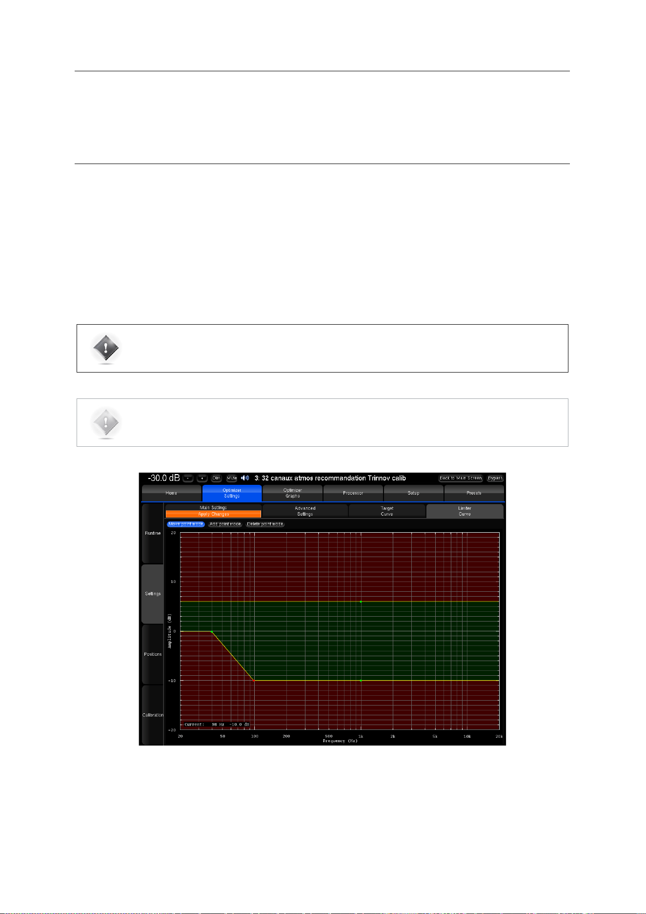
141
17.2 TARGET CURVE
Please see the Setup Target Curves chapter.
17.3 LIMITER CURVE
Unlike the Maximum Boost/Attenuation parameters, the limiter curve allows to setup frequency-dependent maximum
boosts and attenuations. This curve is not engaged by default.
To define a specific limiter curve, go to Optimizer Settings/Settings/Limiter Curve:
• Use the Add point mode and your mouse to create editing points around the required frequency range.
• Use the Move point mode and your mouse to edit the limiter curve for the required frequency range.
• Use the Delete point mode to delete editing points with your mouse.
•
IMPORTANT NOTE: Very steep curves should be avoided.
NOTE: Editing the maximum boost and maximum attenuation limiter curve disables the global
Maximum Boost/Attenuation settings in the Optimizer Main Settings page.
In the example above, the limiter curve will avoid too much attenuation below 100 Hz.
Figure'103:'example'of'a'limiter'curve'fo r 'm a x imum'boo s t/a tt en u a tion'
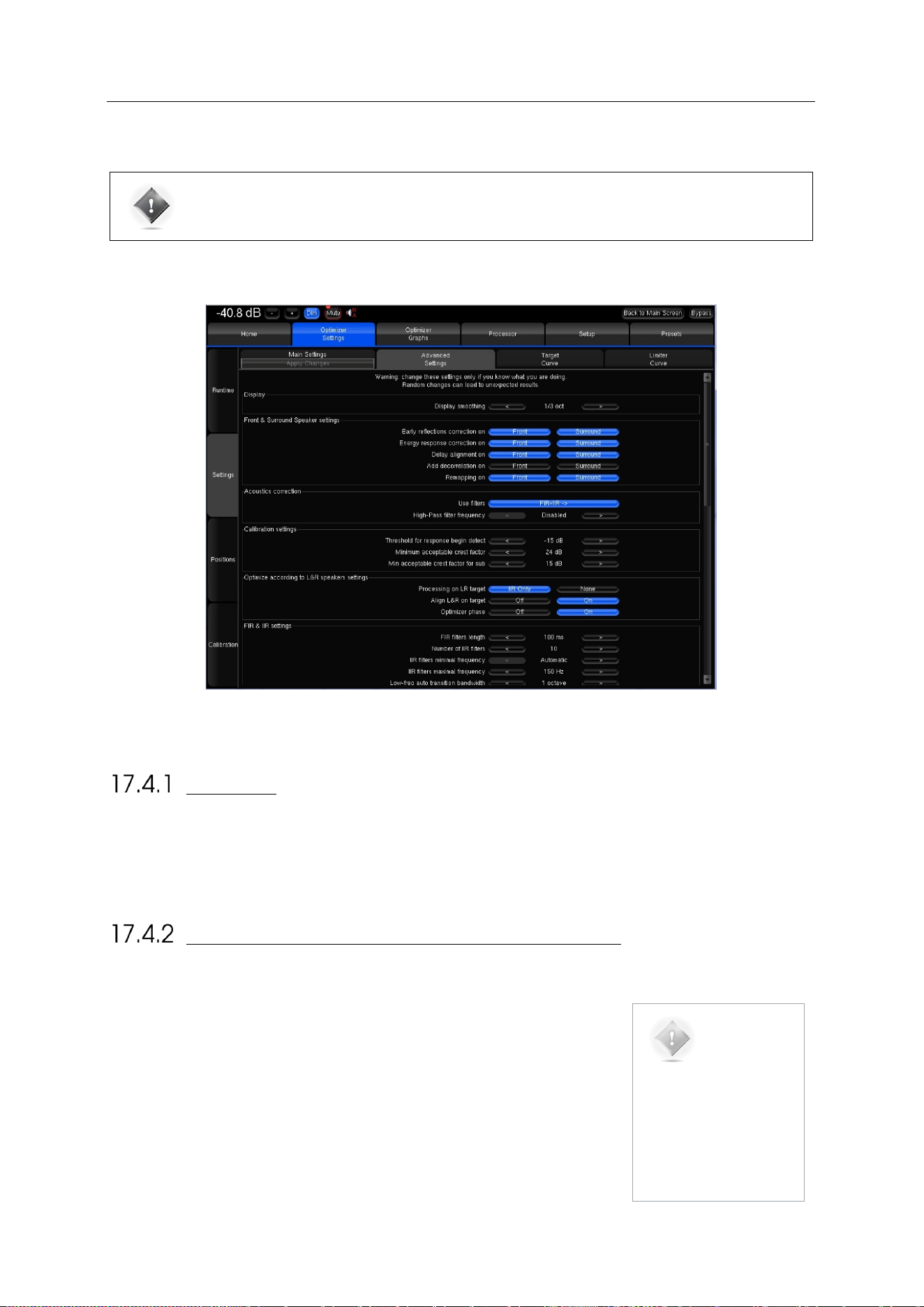
142
17.4 ADVANCED OPTIMIZATION SETTINGS
IMPORTANT NOTE: Change these settings from the recommended settings only if you know what
you’re doing. Random changes can lead to unexpected results.
The SDP-75 provides a large set of advanced settings in the Optimizer Settings/Settings/Advanced Settings page:
Figure'104:'Advanced'optimization'settings'
DISPLAY
The Display smoothing defines the smoothing value used to display the before and after Amplitude Response in the
Optimizer Graphs as well as in the pdf document generated while saving preset. Its default value is (1/3 octave). A smaller
value, such as 1/12 octave, can be used to display more details in the frequency response.
FRONT & SURROUND SPEAKER SETTINGS
The following features can be separately enabled/disabled for the front speakers
and for the surround speakers:
• Early reflections correction;
• Energy response correction;
• Delay alignment, e.g. surround delay alignment may or may not be required
depending on the application and recommendations;
• Add decorrelation: the Optimizer can apply a decorrelation algorithm to the
surround channels in order to simulate the diffuse field created by a belt of
surround speakers;
NOTE: Front
speakers are defined as
those whose azimuth is
below 90 degrees.
Conversely, Surround
speakers are defined as
those whose azimuth is
above 90 degrees.
143
ACOUSTICS CORRECTION
The user can determine the type of filters for the automatic correction:
• FIR + IIR: This is the default setting used by the Optimizer: Both IIR and FIR filters are used to work on the speaker
responses full range;
• FIR only: No IIR filters are used, which means that the Optimizer will only work on the mid and high range of the
speaker responses. The low range will not be optimized;
• IIR only: With this setting, both the automatic FIR and the FIR EQ are disabled. The Optimizer will only use IIR filters
to work on the low range. This setting could be used in specific cases where the user wants to be sure that no FIR
filters at all are applied.
• High-pass filter frequency: Defines the cutoff frequency for the high-pass filter applied to all channels. Can be
disabled.
CALIBRATION SETTINGS
• Threshold for “resp” begin detect: The threshold below the peak level of the impulse that is taken into consideration
to determine the onset of the response. -15 dB is the default value and works in most cases. However, a lower
threshold is recommended in a room with a huge amount of early reflections where the peak might not be detected
correctly.
OPTIMIZE ACCORDING TO L&R SPEAKERS SETTINGS
The Optimizer mode “According to L&R speakers” can be configured with specific settings:
• Processing on L&R target (Default is IIR only): If the optimize mode is set to “Optimize according to L&R speakers”
in the main settings tab, the Optimizer only uses IIR filters on the L&R speakers. This can be switched to “None” to
make sure the L&R speakers are not optimized at all.
• Align L&R on target (Default is On): If this setting is on, the Optimizer applies filters on the Left & Right speakers
using their average response as target. If this setting is off, only the center and surround channels are optimized.
• Optimizer Phase (Default is On): Determines whether the Optimizer should optimize the phase response of the
speakers or not when the L&R speaker mode is on.
FIR AND IIR SETTINGS
FIR stands for Finite Impulse Response. FIR filters are used to optimize amplitude and/or phase.
IIR stands for Infinite Impulse Response. IIR filters are minimum phase filters used by the automatic compensation, in
addition to FIR, for the low frequencies.
• FIR filter length (default is 100ms): Defines the length or number of taps of the FIR filter. The longer the FIR filter,
the higher resolution the correction.
• Number of IIR filters (default is 10): The number of IIR filters that will be used on every channel.
• IIR filters minimal/maximal frequency (default is Automatic/150Hz): IIR filters will be positioned from the min
frequency up to the max frequency. The Automatic parameter uses the minimum frequency of the speaker
bandwidth and the Low-freq auto transition bandwidth parameter to calculate the IIR filter minimal frequency.
• Low-freq auto transition bandwidth (default is 1 octave): Determines the bandwidth of the auto transition. The
auto transition is the frequency range that separates the Optimized frequency range from the unfiltered frequency
range in the low end. The upper boundary of this auto transition bandwidth is the minimal frequency of the
speakers bandwidth.
• Room smoothing method (default is Modulus): For advanced users only.
• Norm used for level_hp (!= align) (default is Room): For advanced users only.
144
LEVEL ALIGNMENT SETTINGS
• Weighting used for levels (default is dBA): Sets the type of weighting used by the optimizer for level alignment.
• Width of level window (default is 16/f): This time-frequency window is used to compute the perceptual level of
every speaker. Its width can be modified to improve the automatic level alignment.
• Maximum/minimum gain on speakers (default is 10dB/-20dB): defines the maximum/minimum gain that will be
applied for the automatic level alignment.
• Minimal/maximal bandwidth frequency (default is 10Hz/Unlimited): defines the high end/ low end of the bandwidth
that is used as the starting point for level computations.
• Bandwidth determination mode (default is Normal): Defines the speakers automatic bandwidth determination
mode from measurements.
SUBWOOFER LOW-PASS FILTER SETTINGS
The Optimizer includes a subwoofer low-pass filter with the following options:
• Cutoff frequency (Default is “disabled”): Defines the cutoff frequency for the low-pass filter that can be applied to
the subwoofer.
• Filter type (Default is Butterworth): Defines the type of filter used at the cutoff frequency. The elliptic filter is sharper
than the Butterworth but shows ripples in the whole bandwidth.
• Filter order (Default is 4): Defines the steepness of the filter. The slope gets stiffer as you increase the filter order.
Please be aware that such changes may result in significant phase shifts
• Rp value (For elliptical filter) (default is 0.1 dB): Sets a maximum amplitude ripple above the cutoff frequency.
• Rs value (For elliptical filter) (Default is 80 dB): Defines the attenuation below the cutoff frequency.
•
DECIMATION SETTINGS & ADVANCED FIR SETTINGS
IMPORTANT NOTE: It is strongly recommended not to change these settings unless you have been
requested to do so by JBL Customer Support.
ADVANCED FIR SETTINGS
IMPORTANT NOTE: It is strongly recommended not to change these settings unless you have been
requested to do so by JBL Customer Support.
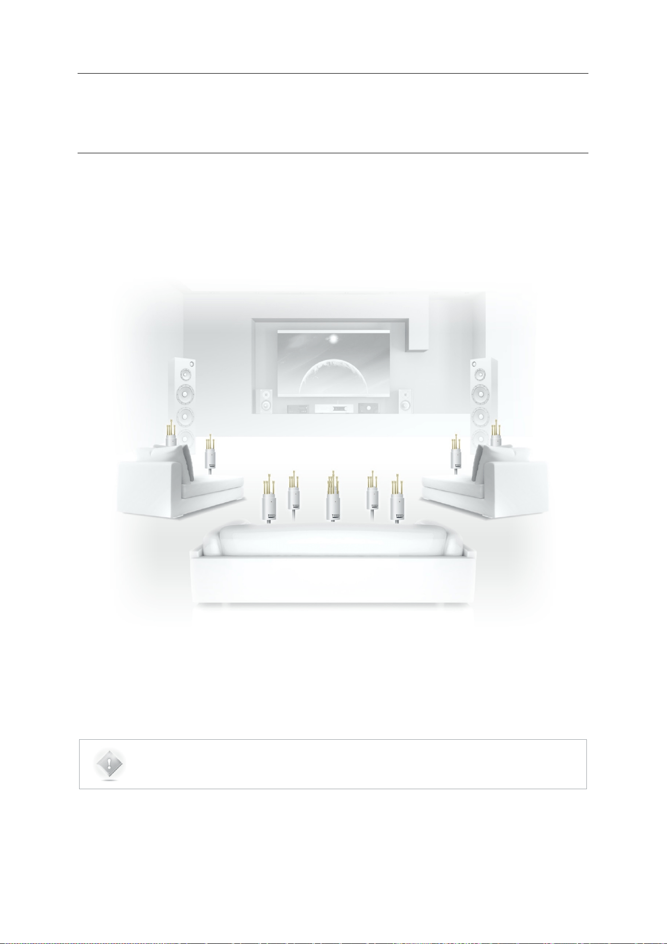
145
18 PERFORMING MULTI-POINT
MEASUREMENTS
One of the most advanced features of the SDP-75 is its unique multi-point measurement technology.
Instead of using an averaged response out of multiple measurement points, the Trinnov Multi-point
Algorithm is able to take every single measurement point into account.
The purpose of multi-point measurement is not only to optimize a wider listening area but also to get
more information from measurements and increase reliability by taking into account important
variations in the listening area.
NOTE: The multi-point approach ensures a more reliable calibration but choosing relevant microphone
positions is highly critical.
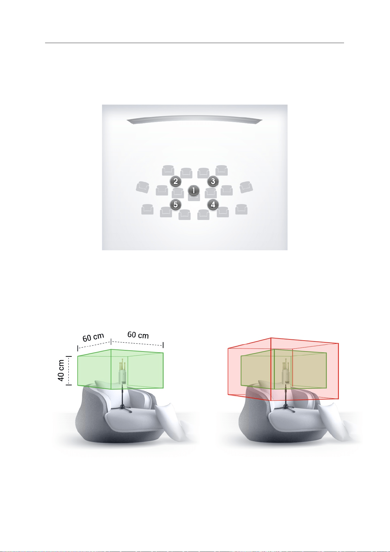
146
18.1 RELEVANT MEASUREMENT POSITIONS
There are no fixed rules about choosing multi-point measurement positions. However, the
microphone positions chosen has a profound impact on the quality of the results.
Figure'105:'Relevant'multi-point'measuremen't'positions'
As an example, multi-point measurements can be performed for a single listening position:
'
Figure' 106:' Relevant' multi-point' measurement' area' for' a'
single'listening'position'
'
Figure' 107:' Relevant' (green)' /' irrelevant' (red)' multi-point'
measurement'area'for'a'single'listening'position'
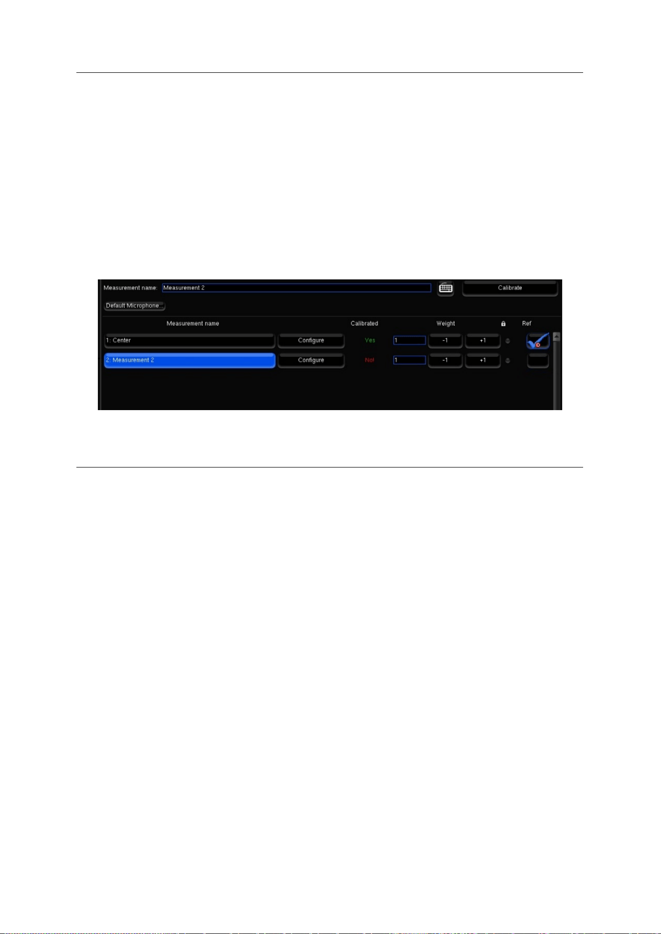
147
18.2 MULTI-POINT CALIBRATION PROCEDURE
Multi-point measurements can be performed sequentially using the same microphone.
You can add a new measurement by pressing the “Add” button at the bottom of the page, or delete the selected
measurement by pressing “Delete”. You can also rename a measurement by editing the text box "Measurement name".
For each measurement, the “Calibrated” column indicates “Yes” if the measurement has been correctly performed, “No”
if it has not, and “Partial” if the calibration was interrupted before completion.
Each measurement contains the responses recorded during the calibration sound sequence.
Select the required measurement and press the “Calibrate” button to launch the calibration sequence.
Once every measurement has been calibrated, you can compute the acoustic correction filter that will best fit every point,
accordingly to their weight.
Figure'108:'List'of'measure ments'
18.3 WEIGHTING MULTIPLE MEASUREMENTS
The “Weight” column allows you to set a weight to each measurement, from 0 to 100, to emphasize, for example, some
central points. You can bypass some points by setting their weight to 0, which can be useful in case one of the points
have failed the calibration but you don’t want to perform a calibration again.
The weight can be adjusted after a calibration; you don’t have to run a complete calibration to take weight changes into
account, just to press once the “Compute” button.
You can adjust the weight of the measurements with your mouse clicking on +1 or -1, or with your keyboard, with the up
(+1) and down (-1) arrows, or the page up (+10) and page down (-10) keys.
• All the measurements with non-null weight should be fully calibrated before computing the acoustic correction
filters by pressing the “Compute” button. If some are partially or not calibrated at all, you will have to remove the
bad points or their entire measurements, for example by setting their weight to 0, before being able to compute the
acoustic filters.
• The lock disables measurement settings edition.
• The “ref” column indicates which measurement is the reference point. The reference point is unique, it can be
modified after the calibration. Taking a new measurement into account as reference point requires to recompute
the compensation filters.
• Before saving your preset in the “Presets” page, you have to save the multipoint parameters by pressing the “Save
changes” button. These parameters are automatically saved (and the button disabled) when you leave the point
list, and when you run a calibration or a computation.
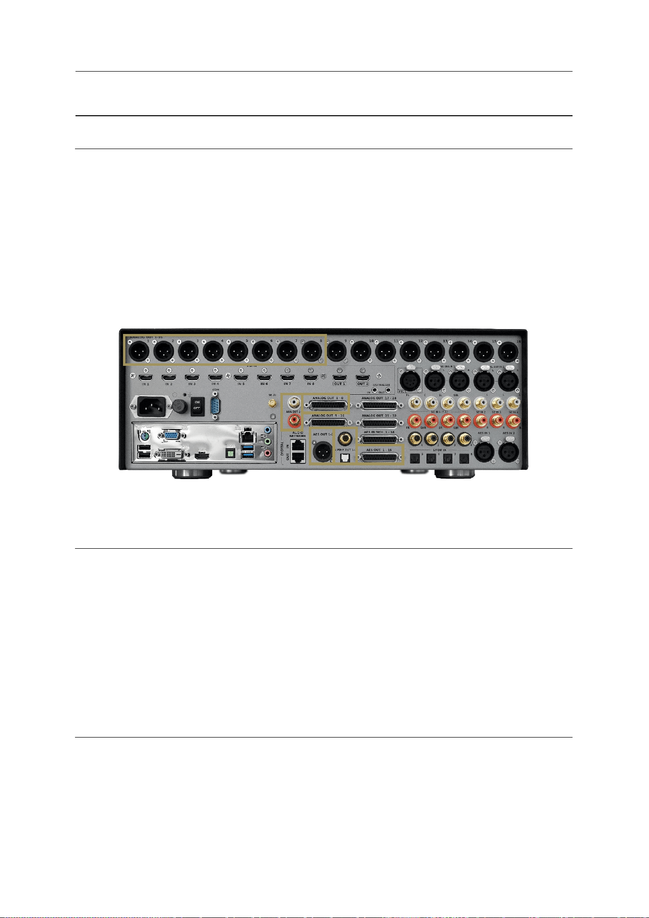
148
19 APPENDIX
19.1 INSERT AN EXTERNAL STEREO DAC
As the SDP-75 has a flexible and complete range of output types, allowing the use of other DACs when desired.
The analog outputs 1-8 are duplicated on the AES outputs 1-8.
The analog outputs 1-2 are duplicated on the stereo analog SE outputs, AES outputs 1-2, as well as the SPDIF RCA and
optical stereo outputs.
Make sure that the routing is correct.
It’s up to you to choose the best way to feed you external DAC.
Figure'109:'Duplicated'O u tp u t s'
19.2 REMOTE START AND STOP
The SDP-75 can be remotely switched on via a Wake-on-LAN network message. Please ask a certified installer or an
experienced IT technician for technical support.
It can also be switched off remotely over the network using the command provided within our automation protocol for
that purpose, available for download on http://www.jblsynthesis.com.
The trigger input can also be used to switch the SDP-75 on and off from another device.
More information can be provided upon request.
19.3 AUTOMATION
The SDP-75 can be remotely controlled from an automation system through RS232 or Ethernet. As an example, it is
possible to create a Crestron® module to remotely control the SDP-75 via RS232.
The specifications of the protocol are publicly available and can be downloaded from the Products / Electronics /
Surround Sound Preamplifiers / SDP-75 / Downloads / Software section of the JBL Synthesis website:
http://www.jblsynthesis.com
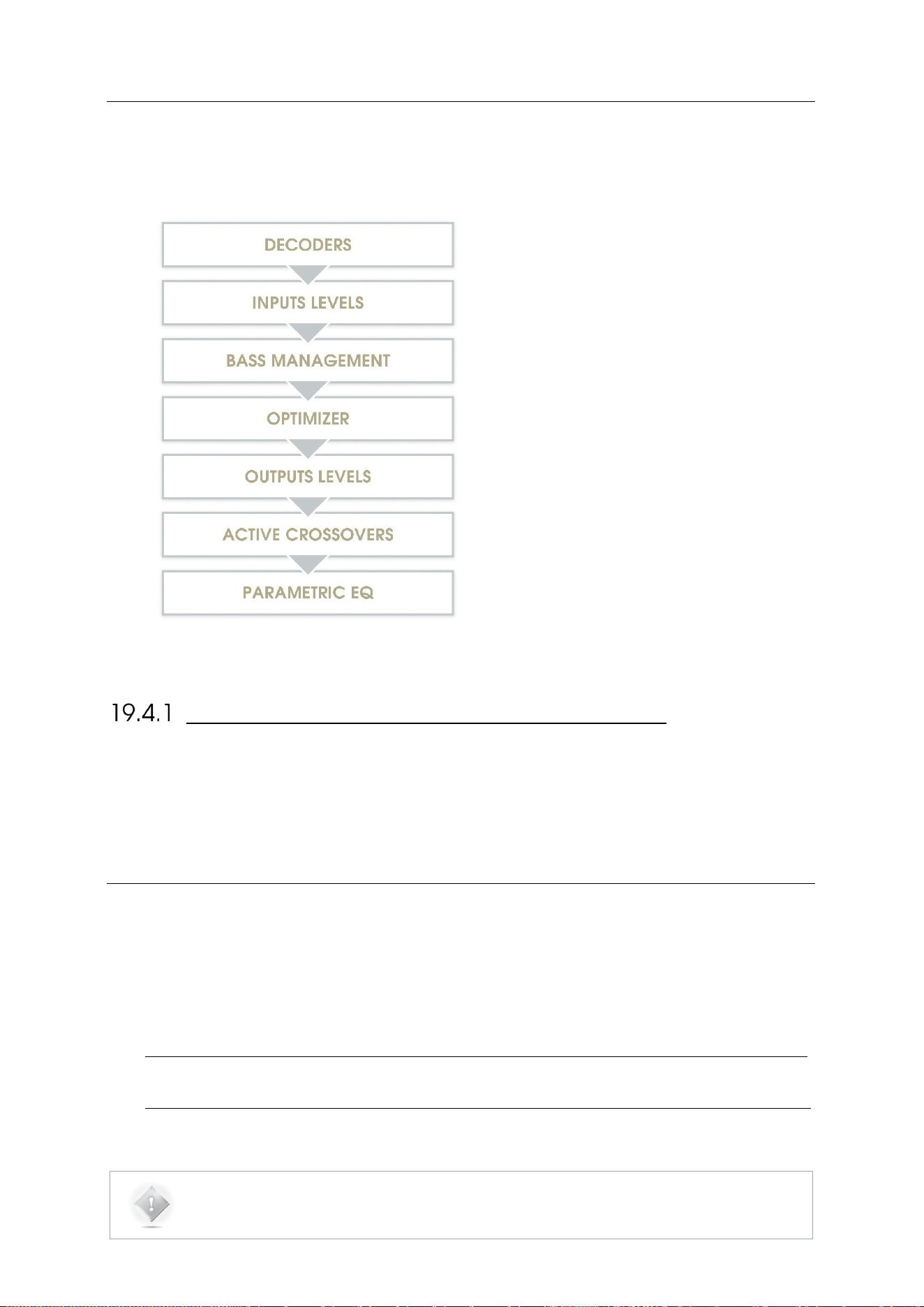
149
19.4 SIGNAL FLOW OF THE SDP-75
Not shown:
• Input & output routing / Physical inputs &
outputs
• Manual input & output Eqs
SETUP PROCESS AND FILTERS CALCULATION
Active-Crossovers are set up first following a semi-automatic calibration procedure.
The Optimizer’s filters calculation is made from the speaker measurement.
Bass management crossover filters are applied after and regardless of the loudspeaker calibration. The crossover
frequencies and bass management mode can therefore be modified after calibration.
19.5 3D SPEAKER PLACEMENT
RECOMMENDATIONS
For detailed information about speaker placement recommendations, please refer to the following documents:
• Auro-3D Home Theatre Setup Installation Guidelines, available from Auro Technologies.
• http://www.auro-3d.com/wp-content/uploads/documents/Auro-3D-Home-Theater-Setup-Guidelines_lores.pdf
• Dolby Atmos Home Theatre Installation Guidelines, available from Dolby:
• http://www.dolby.com/us/en/technologies/dolby-atmos/dolby-atmos-home-theater-installation-guidelines.pdf
NOTE: As of July 2016, the DTS X Home Theatre Installation Guidelines are not yet available.
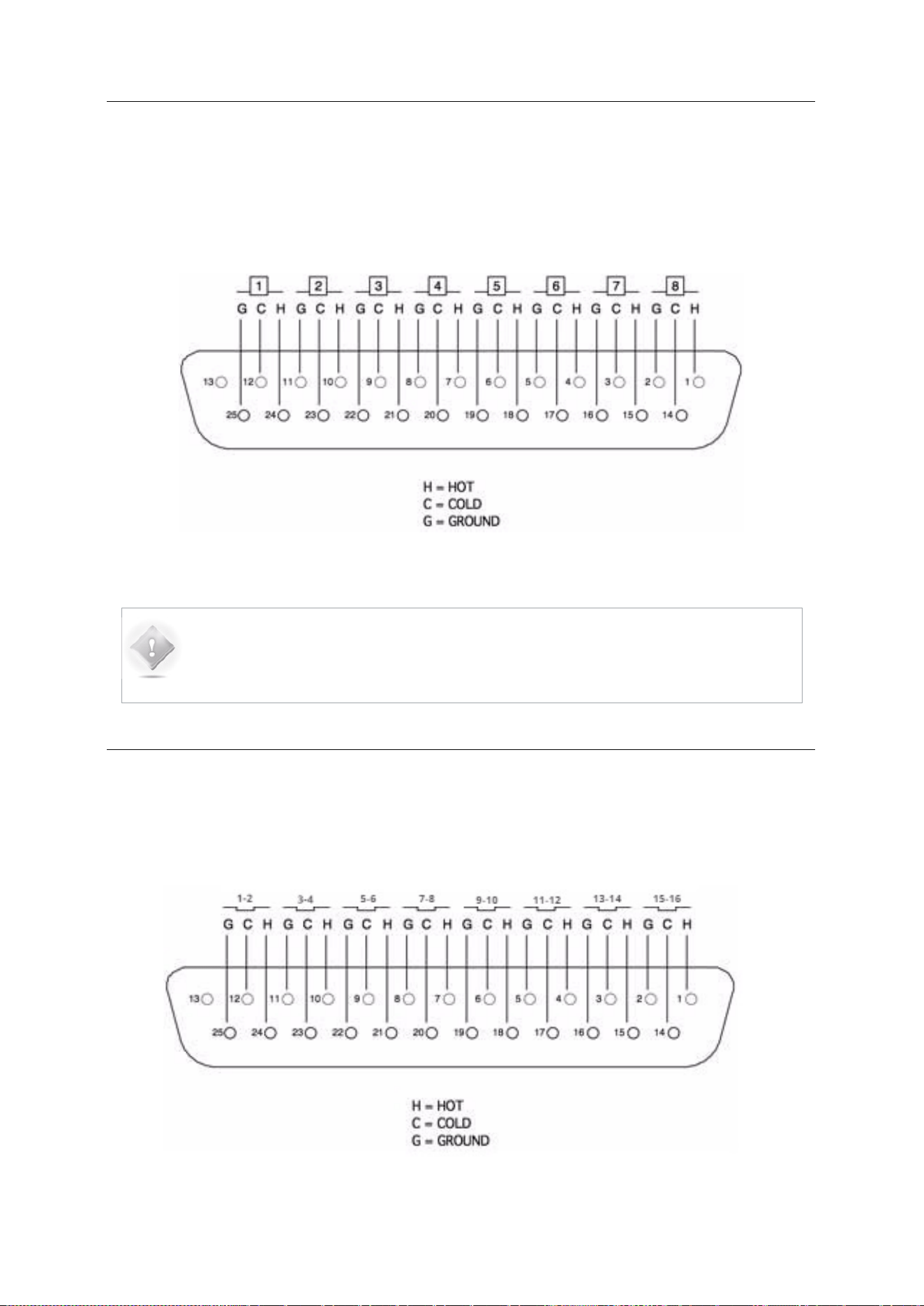
150
19.6 DB25 CONNECTOR: ANALOG PINOUT
PINOUT
The SDP-75 uses DB25 connectors for Analog output connections. We use the widely-used Tascam DB25 scheme
described below.
Figure 110: Tascam pinout for the AES DB25 output connector
NOTE: Another quite popular pinout is the one from Yamaha. You should check which pinout
your equipment is using before connecting it to the SDP-75. Unbalanced connections must
connect signal to SubD-Hot and shield to SubD-Cold.
19.7 DB25 CONNECTOR : AES PINOUT
The SDP-75 uses DB25 connectors for AES connections, input as well as output. We use the widely-used Tascam
DB25 scheme described below.
Figure'111:'Tascam'pino u t 'fo r'th e 'A E S 'D B 2 5 'o u tput'conne c to r'
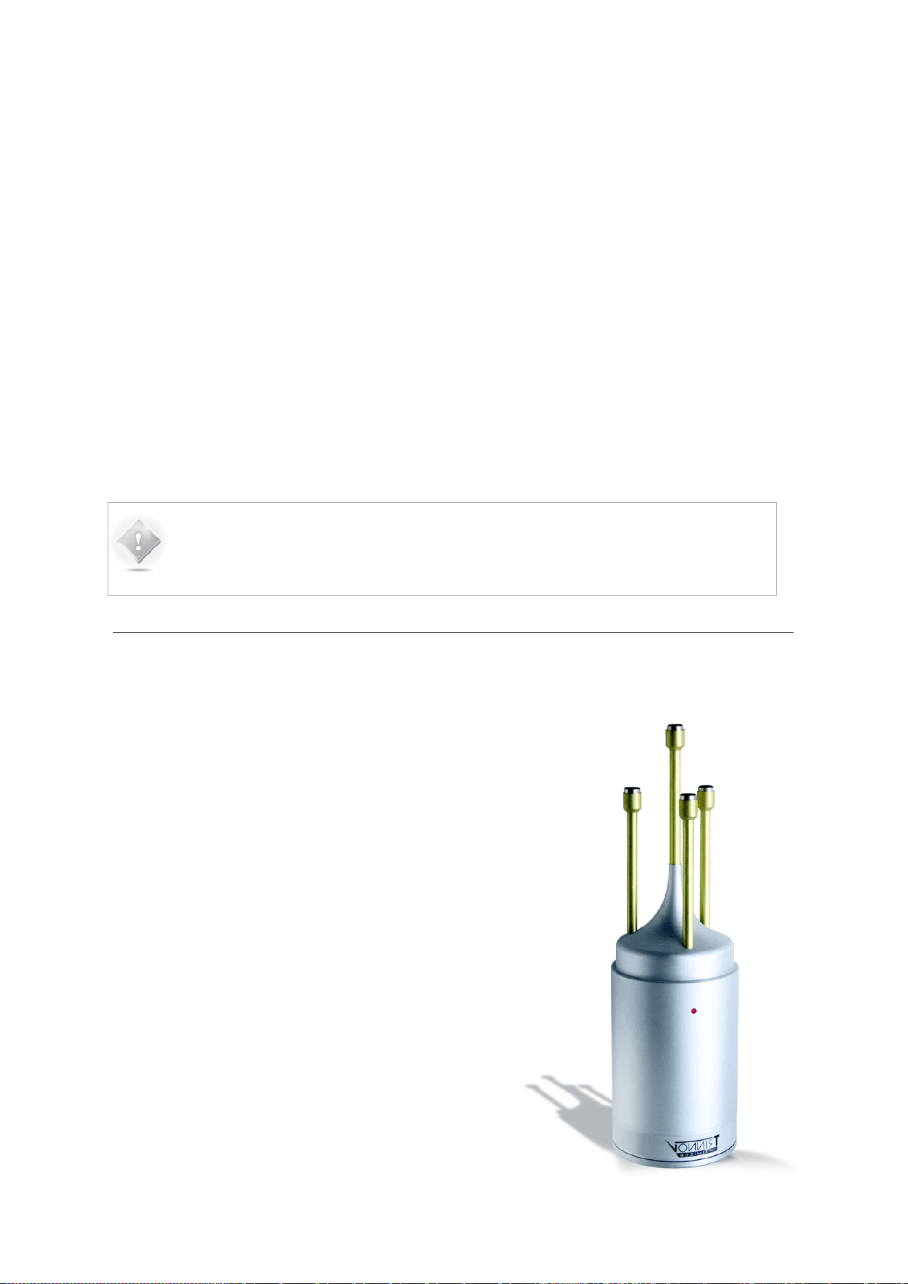
151
19.8 3D MEASUREMENT MICROPHONE
The purpose of the calibration microphone is to measure
the characteristics of the loudspeaker and their layout in
the room.
For each loudspeaker, the Optimizer gathers the following
information:
• full 3D position
• amplitude response
• phase response
NOTE: Another quite popular pinout is the one from Yamaha. You should check which pinout
your equipment is using before connecting it to the SDP-75. Unbalanced connections must
connect signal to SubD-Hot and shield to SubD-Cold.
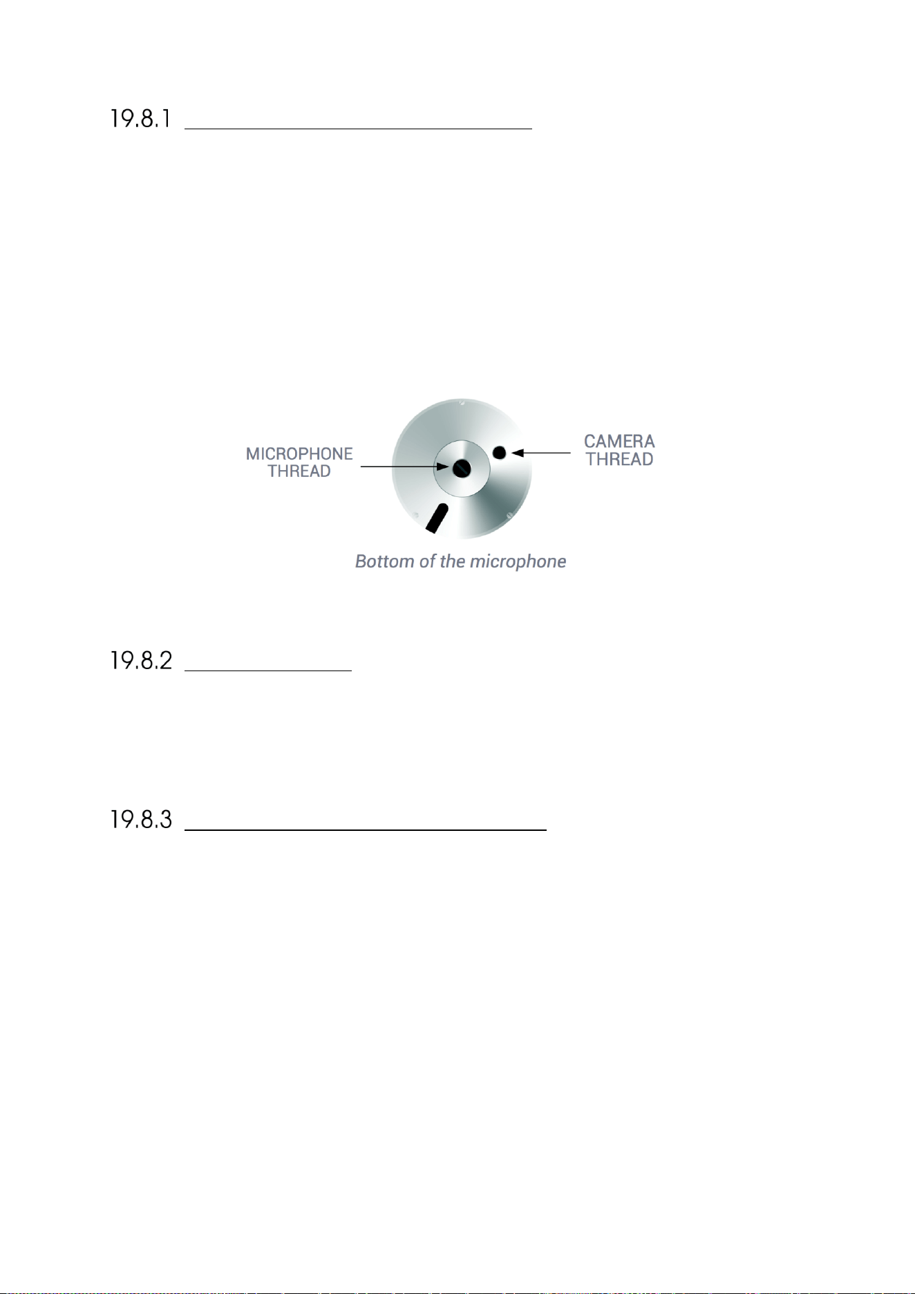
152
MICROPHONE SPECIFICATIONS
• 4 capsules in tetrahedron configuration.
• Individual compensation filters
• Frequency response within +/- 0.1dB across the 20Hz-24kHz frequency range
• Spatial resolution below +/-2°
• Built-in preamp
• A 9V PP3 LR61 battery powers capsules and electronics
• Camera / Microphone thread.
POWER SUPPLY
The power supply located in the base of the microphone uses a standard 9V PP3 LR61 battery. The red led indicates the
battery Level. Replacing the battery requires removing the 3 screws at the bottom of the microphone.
INDIVIDUAL COMPENSATION FILE
The individual compensation file of the microphone used by the SDP-75 can be modified in the Optimizer
Settings/Calibration page.
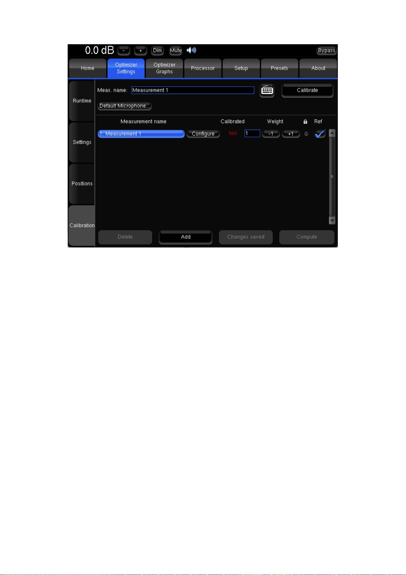
153
Calibration'page'
Always make sure the microphone serial number indicated in the Configure page matches the label at the bottom of your
microphone. If not, use the Configure button of the required Measurement to select the correct compensation file.
For future measurements, use the Default Microphone button to make the required compensation file automatically
selected in the preset.
The 3D localization of the speakers can only be performed if the connection order of the capsules is respected.
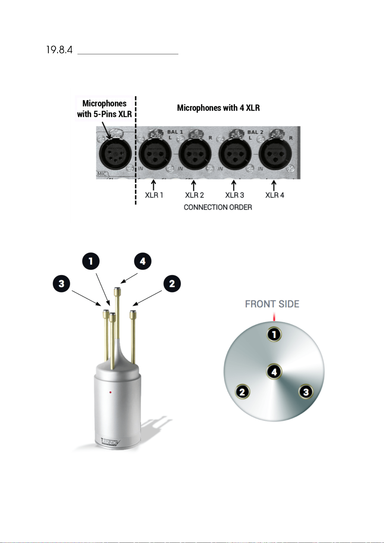
154
CONNECTION ORDER

155
Thank!you!for!your!attention!
Please!enjoy!your!Sound.

156