Before troubleshooting or servicing equipment, review equipment installation guides and conrm ALL installation
requirements & specications have been met. Including, but not limited to: wiring, clearance, ducting (where applicable),
power, and line set requirements. Correct any installation issues before continuing.
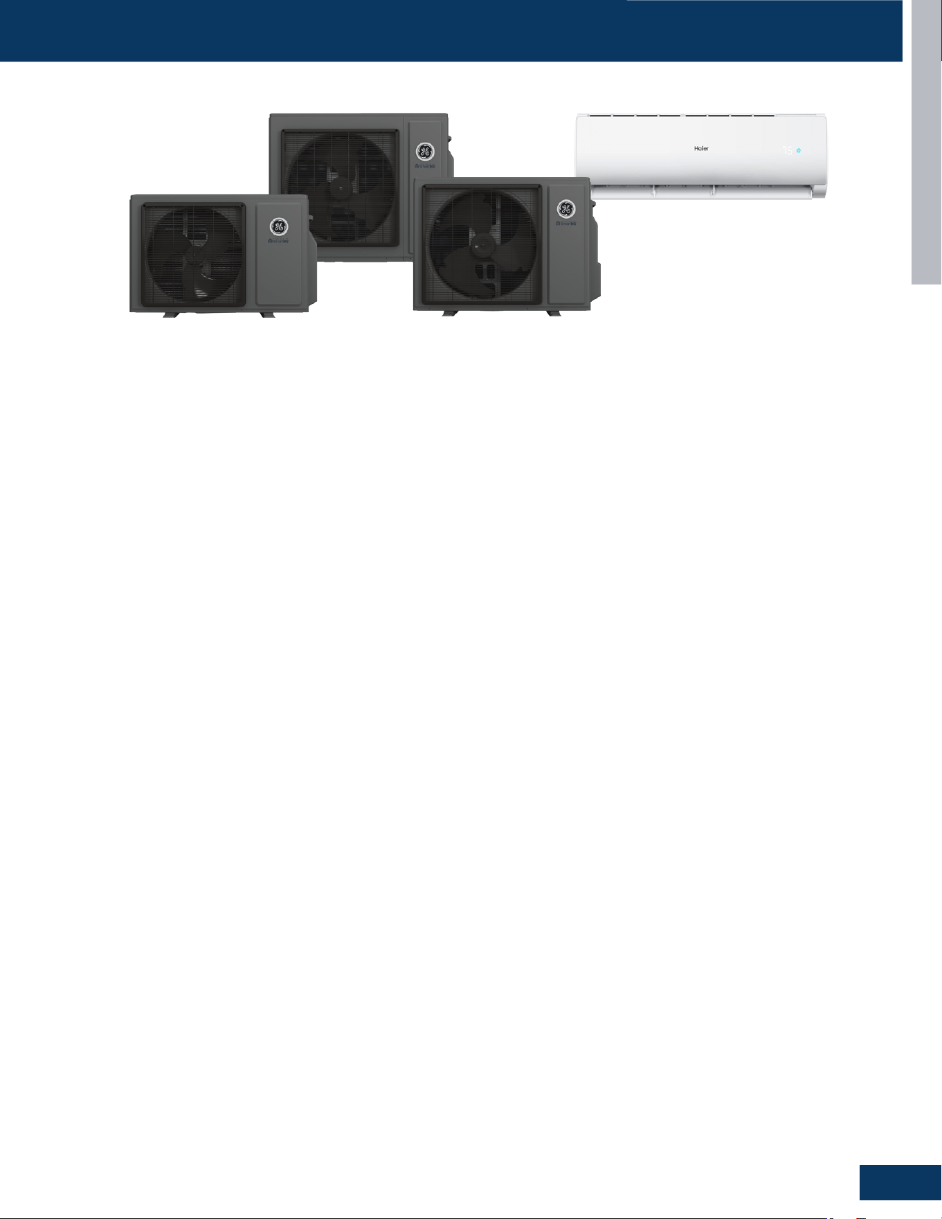
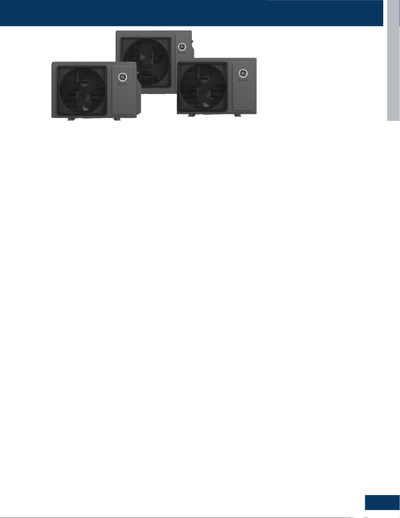
Single Zone
Service Manual
Ductless Split Heat Pumps
1G09CB2BEA / GS09WB2BEA
1G12CB2BEA / GS12WB2BEA
1G18CB2BEA / GS18WB2BEA
1G24 CB2BEA / GS24WB2BEA

TABLE OF CONTENTS
10-16-25: Edition release.
Revision History
Introduction ................................................................................................................ A1
Outdoor Units
............................................................................................................. B1
Highwall Indoor Units
.................................................................................................. C1
Troubleshooting & Reference
...................................................................................... D1
INTRODUCTION
A1
ENGLISH
INTRODUCTION
SAFETY & PRECAUTIONS .......................................................................................................................................................A2
SPECIFICATIONS
....................................................................................................................................................................A3
OVERVIEW
..............................................................................................................................................................................A4
Introduction to System ..........................................................................................................................................................A4
SpecicationsforProperOperation .....................................................................................................................................A4
SystemFundamentals ............................................................................................................................................................A4
SystemPower .........................................................................................................................................................................A4
FUNCTIONS AND CONTROL ..................................................................................................................................................A5
CoolingOperationMode ........................................................................................................................................................ A5
HeatingOperationMode .......................................................................................................................................................A6
AutoMode ............................................................................................................................................................................... A7
DryMode .................................................................................................................................................................................A7
DefrostOperation ..................................................................................................................................................................A8
ProtectionFunctions ..............................................................................................................................................................A8
SpecialFunctions ....................................................................................................................................................................A9
TABLE OF CONTENTS
INTRODUCTION
A2
ENGLISH
SAFETY & PRECAUTIONS
FOLLOW ALL WARNINGS, CAUTIONS, AND PRECAUTIONS BELOW, AND INDUSTRY BEST
SAFETY PRACTICES AND STANDARDS. FAILURE TO DO SO MAY RESULT IN EQUIPMENT
DAMAGE OR FAILURE, AND SERIOUS PERSONAL INJURY OR DEATH.
!
WARNINGS
Service should be performed by the dealer or another professional.
Improperservicemaycausewaterleakage,electricalshock,orre.
Use only the supplied or specied service parts.
Useofotherpartsmaycausetheunittocomelose,waterleakage,electricalshock,orre.
The heat pump must be installed on a solid base that can support the unit’s weight.
Aninadequatebaseorincompleteinstallationmaycauseinjuryintheeventtheunitfallsothebase.
Electrical work should be carried out in accordance with the manual and national/local electrical wiring codes and rules of practice.
Insucientcapacityorincompleteelectricalworkmaycauseelectricalshockorre.
A dedicated power circuit must be used. The power supply should NEVER be shared by another appliance.
Wiring cable must be long enough to cover the entire distance with no splices.
Donotuseanextensioncord.Donotputotherloadsonthepowersupply,useadedicatedpowercircuit.
Failuretodosomaycauseabnormalheat,electricshockorre.
Only the specied wire types may be used for electrical connections between the indoor and outdoor units.
Firmlyclamptheinterconnectingwiressotheyreceivenoexternalstresses.Incompleteconnectionsorclampingmaycauseterminal
overheatingorre.
Wiring must not put undue stress or tension on the electrical covers or panels.
Installcoversoverthewires.Incompletecoverinstallationmaycauseterminaloverheating,electricalshock,orre.
If any refrigerant has leaked out during service work, ventilate the room.
Therefrigerantproducesatoxicgasifexposedtoame.
After all service is complete, check for and repair any system refrigerant leaks.
Therefrigerantproducesatoxicgasifexposedtoames.
When servicing or relocating the system, keep the refrigerant circuit free from substances other than the specied refrigerant
(R454B), such as air or moisture
Thepresenceofairorotherforeignsubstanceintherefrigerantcircuitcausesanabnormalpressureriseorrupture,resultingininjury.
During pump-down, stop the compressor before removing the refrigerant piping.
Ifthecompressorisstillrunning,andthestopvalveisopenduringpump-down,airwillbesuckedintothesystemwhilethecompressor
isrunning.Thiswillcauseabnormalpressureandnoncondensablesaddedtothesystem.
Unit must NOT be grounded to a utility pipe, arrester, or telephone line ground.
Ancompletegroundmaycauseelectricalshock,orre.Ahighsurgecurrentfromlightningorothersourcesmaycausedamagetothe
heatpump.
CAUTIONS
The heat pump must not be installed in a place where there is danger of exposure to ammable gas.
Ifthegasbuildsuparoundtheunit,itmaycatchre.
Drain piping must comply with installation guidelines.
Inadequatepipingmaycauseooding.
Tighten are nuts according to the specied torque using a torque wrench.
Ifarenutsareovertightened,theymayeventuallycrackandcauserefrigerantleakage.
Ensure proper clearances around unit per installation guidelines.
INTRODUCTION
A3
ENGLISH
Outdoor Unit 1G09CB2BEA 1G12CB2BEA 1G18CB2BEA 1G24CB2BEA
Indoor Unit GS09WB2BEA GS12WB2BEA GS18WB2BEA GS24WB2BEA
Cooling
RatedCapacityBtu/hr 9,000 11,800 17,000 24,000
CapacityRangeBtu/hr 3,400-10,000 3,400-12,000 6,000-17,500 6,500-25,000
SEER2 23 21 20 18
EER2 12 12 12 12
MoistureRemovalPt./hr 2.6 2.7 3.6 4.9
Heating
RatedHeatingCapacity47°FBtu/hr 10,000 13,000 19,000 24,000
HeatingCapacityRangeBtu/hr 3,400-11,000 3,400-13,500 6,000-21,000 6,500-26,000
HSPF2(IV) 9.5 9.5 9.5 9.5
RatedHeatingCapacity5°FBtu/hr 8,000 10,400 15,200 19,200
HeatingCapacityat5°F/Capacity
at47°F
80% 80% 80% 80%
COP5°F 1.8 1.8 1.8 1.8
Operating
Range
Cooling
(WithoutWindBaeorTopCover)
23~115°F(-5~46°C) 23~115°F(-5~46°C) 23~115°F(-5~46°C) 23~115°F(-5~46°C)
Heating -4~75°F(-20~24°C) -4~75°F(-20~24°C) -4~75°F(-20~24°C) -4~75°F(-20~24°C)
Power Supply
Voltage,Cycle,Phase(V/Hz/-) 208-230/60/1 208-230/60/1 208-230/60/1 208-230/60/1
MaximumFuseSizeA 10 10 20 30
MinimumCircuitAmpA 9 9 15 20
Outdoor Unit
Compressor Type DCInverterRotary DCInverterRotary DCInverterRotary DCInverterRotary
OutdoorNoiseLeveldB 55 55 58 61
Dimension:Heightin(mm) 213/4(553) 213/4(553) 251/4(642) 321/8(815)
Dimension:Widthin(mm) 34(863) 34(863) 353/8(898) 403/8(1024)
Dimension:Depthin(mm) 11(280) 11(280) 12(306) 145/8(370)
Weight(Net/Ship)-lbs(kg)
70.17/82.96
(31.8/37.6)
70.17/82.96
(31.8/37.6)
90.47/103.26
(41/46.8)
121.36/147.84
(55/67)
BasepanHeater No No No No
Indoor Unit
FanSpeedStages 5 + Auto 5 + Auto 5 + Auto 5 + Auto
AirowCFM:Cooling
(Turbo/High/Med/Low/Quiet)
360/290/260/230/210 360/300/272/240/210 570/520/480/420/330 800/730/630/535/440
AirowCFM:Heating
(Turbo/High/Med/Low/Quiet)
350/290/250/220/200 350/290/260/230/200 570/520/450/380/310 800/730/630/535/440
IndoorSoundLeveldB:Cooling
(Turbo/High/Med/Low/Quiet)
44/38/35/32/27 44/39/36/33/27 50/46/44/40/35 54/50/47/44/38
IndoorSoundLeveldB:Heating
(Turbo/High/Med/Low/Quiet)
42/36/32/28/26 42/36/32/29/26 48/46/41/38/33 54/50/47/44/38
AutoUp-DownLouver Ye s Yes Ye s Yes
AutoLeft-RightLouver No No No No
DrainPipeSizeO.Din 5/8 5/8 5/8 5/8
Dimension:Heightin(mm) 117/8(301) 117/8(301) 127/8(327) 131/2(343)
Dimension:Widthin(mm) 341/4(870) 341/4(870) 393/8(999) 441/2(1129)
Dimension:Depthin(mm) 73/4(196) 73/4(196) 83/4(223) 91/8(232)
Weight(Net/Ship)-lbs(kg)
21.84/26.92
(9.9/12.2)
21.84/26.92
(9.9/12.2)
27.8/34.64
(12.6/15.7)
34.86/43.03
(15.8/19.5)
Factory-InstalledRefrigerant
DetectionSensor(RDS)
No No No No
RefrigerantDetectionSensor(RDS)
Compatible
Yes
(UALS01A,soldseparately)
Yes
(UALS01A,soldseparately)
Yes
(UALS01A,soldseparately)
Yes
(UALS01A,soldseparately)
WiFi*
Built-in Built-in Built-in Built-in
Refrigerant
Lines
Refrigerant R454B R454B R454B R454B
Connections Flare Flare Flare Flare
LiquidO.D.in 1/4 1/4 1/4 1/4
SuctionO.D.in 3/8 3/8 1/2 1/2
FactoryChargeOz 36.5 36.5 45.9 67.0
MaximumLineLengthFt/m 66/20 66/20 83/25 165/50
MaximumHeightFt/m 33/10 33/10 50/15 100/30
SPECIFICATIONS
Ourcontinuedcommitmenttoqualityproductsmaymeanachangeinspecicationswithoutnotice.
VisitGEAppliancesAirandWater.comtoaccesscurrentspecicationtablesonline.
NOTE
*WiFi includes SmartHQ
TM
Home and SmartHQ
TM
Service compatibility.

INTRODUCTION
A4
ENGLISH
OVERVIEW
Introduction to System
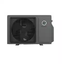
SingleZoneDuctlessSplitSystemHeatPumpsfeatureawallmountedindoorfan/evaporatorunitthatreceivesrefrigerantfromaninverter
drivenvariablespeedoutdoorcondensingunit.Thesystemoperationiscontrolledwitharemotecontrol.
Theoutdoorunitfeaturesavariablespeedrotarycompressor,EEVmeteringdeviceandDCfanmotor.ThesesystemsuseR454Brefrigerant
andPVEoil.Theoutdoorunitsare208/230voltratedsystems.
Theindoorunitsarewallmounted.TheyfeatureaDCblowermotorandaDClouvermotor.Theunithasaroomtemperaturesensorandan
evaporatortubetemperaturesensor.Thewallunitispoweredbyvoltagefromtheoutdoorunit.
Specications for Proper Operation
Thesystemsaredesignedtooperateintemperaturerangesof23~115°Fincoolingmodeand-4~75°Finheatmode.
PVEoilisnon-reactivetowaterandwillnotgointohydrolysis.Thereisnoneedtoaddarefrigerationdrierwhenservicingorinstallingthis
system.
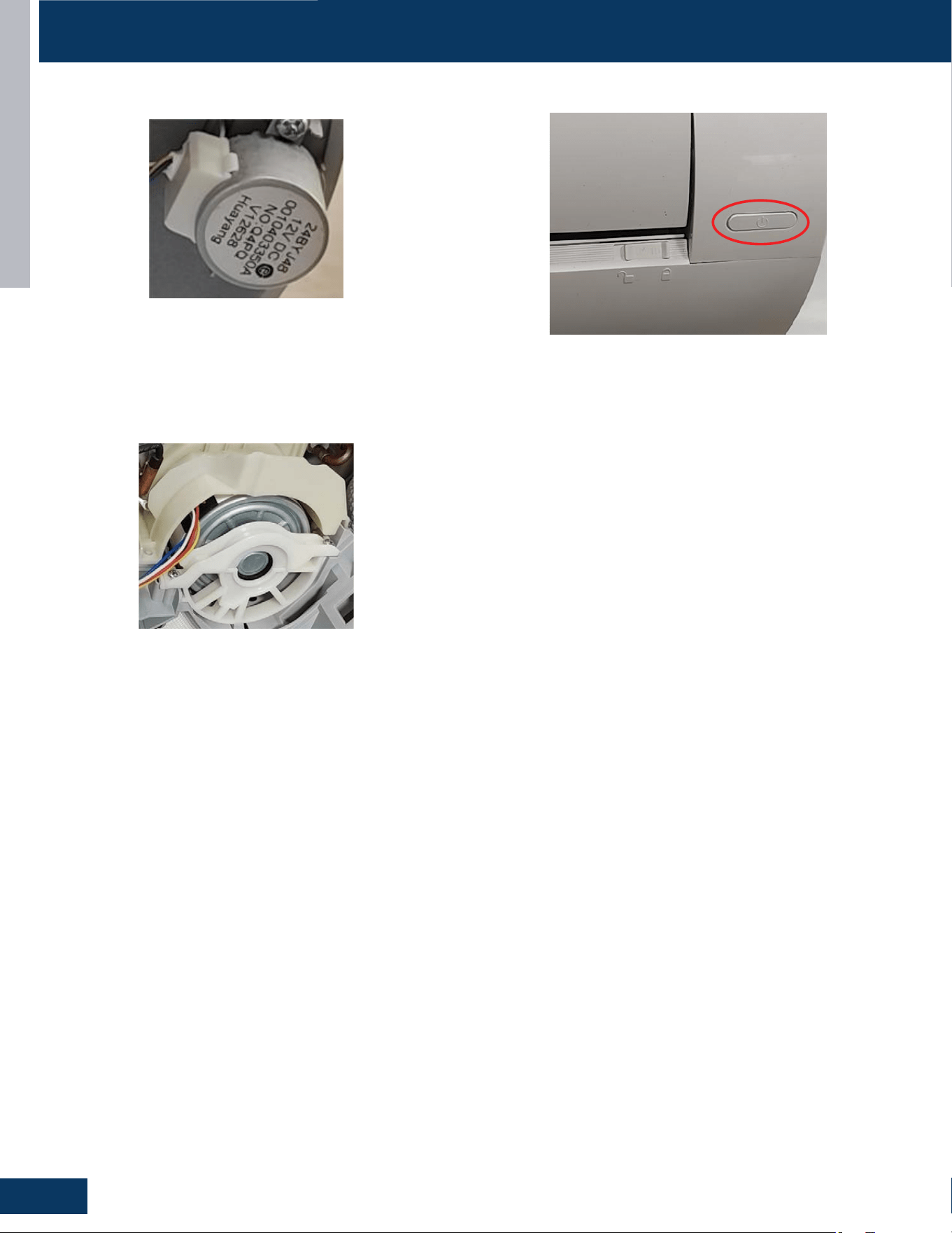
Theindoorwallmountedunitreceivesoperatingvoltageandcommunicationdatasignalson#14AWGwirethatconnectsbetweentheindoor
andoutdoorunits.Thereshouldnotbeanysplicesintheeldwiringthatgoesbetweenterminals1,2,3GND.Aspliceinthesewiresmaycause
thesystemtolosecommunicationbetweentheindoorandoutdoorunits.
Theeld-suppliedrefrigeranttubingconnectsusingaretypettingsatboththeindoorandoutdoorunits.Tubingmustbesizedperthe
specications.Bothlinesmustbeinsulated.Theonlymethodofcheckingchargeoradjustingchargeisbyweightmethodexplainedinthis
manual(noexceptions).
Thecondensatesystemisagravitytype.Aeldinstalledcondensatepumpmaybeaddedtothesystem.Alwaysfollowthemanufacturer’s
installationinstructionswheninstallingacondensatepump.
Properclearancesatbothindoorandoutdoorunitsmustbemaintained.Improperclearancescauseincorrectrefrigerantpressuresandcoil
freezing.
System Fundamentals
Theindoorunitwillsenseroomtemperatureatthepointwherethewallunitisinstalled.Theindoorfanwillruncontinuouslywhenplacedin
heatingorcoolingmodeandwillnotcycleonandowiththeoutdoorunit.Ifitdid,roomtemperaturecouldnotbesensedormaintained.
Theinvertercompressorsystemintheoutdoorunitwillvarytherefrigerantowandindoorairvolumelevelstomatchthecomfortrequirement
insidetheconditionedspace.Ifanabnormalconditionisdetectedbythesystem’ssensors,thesystemhastheabilitytotakereactivemeasures.
Theamountofrefrigerantowandassociatedcapacitygeneratedbythesystemwillbedeterminedbyhowfastthesystem’svariablespeed
rotarycompressorispumping.Thecompressoroperatingspeedisdeterminedbythedierencebetweentheconditionedspacetemperature
andthesetpoint.
Ifalargeamountofcapacityisneeded,thecompressorwilloperateatahighspeed.Astheneedforcapacityreducesandthetemperatureof
theroomnearssetpoint,thecompressorwillslowdown.Whensetpointhasbeenreached,thecompressorwillshutowhilethefancontinues
tooperate.Whenadierenceintemperatureissensedbetweenthesetpointandroom,thecompressorwillrestartatanewcalculatedspeed.
Ifasystemsensordeterminesthereisaneedtoadjustthefrequencysignaltopreventasystemmalfunction,thecompressorfrequencymay
beoverriddenandanewfrequencyestablished.Itshouldbenotedthatthefrequencysignallevelthatissenttothecompressorcannotbe
determinedbyaservicingtechnician.
Inthismanual,systemcomponents,operation,sensorfunctions,anddiagnosticprocedureswillbeexplainedingreaterdetail.
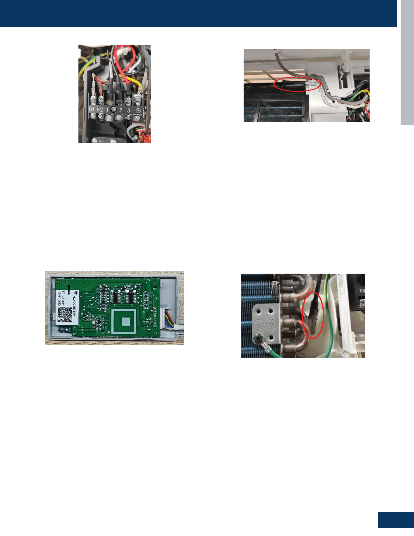
System Power
The208/230VoltACpowerforthesystemconnectstoterminals1,2,andgroundoftheoutdoorunitterminalblock.Thisterminalblockalso
hasterminalstoconnectpowertotheindoorunit.
Thevoltagereadingsbetweenterminals1andgroundshouldbe0VAC,andterminals2andgroundshouldbe230VAC.Thevoltagereading
betweenterminals1and2shouldbe230VAC.
Oneadditionalconnectionontheterminalblock(3)isforthecommunicationwirebetweentheindoorandoutdoorunits.
NOTE:Miswiringoftheseconnectionsmaycauseimproperoperationordamagetosystemcomponents.
INTRODUCTION
A5
ENGLISH
FUNCTIONS AND CONTROL
Cooling Operation Mode
Overview
Thetemperaturecontrolrangeincoolingmodeis23°Fto115°F.The
temperaturesetbytheremotecontrolandtheindoorunitambient
temperaturesensorwilldetermineifacallforcoolingisneeded.Ifa
callforcommunicatedfromtheindoorunittotheoutdoorunit.The
indoorunitlouverwillopenusingasteppermotor,andtheindoorfan
willoperateatthespeedlastset.Theoutdoorunitwilldeterminethe
positionoftheEEVandspeedfrequencyofthecompressor.There
canbeadelayofupto3minutesbeforetheoutdoorunitfanand
compressorstart.
Thespeedoftheindoorfancanbecontrolledmanuallybytheuser
orautomaticallybythesystem.Thespeedcanbechangedbetween
LOW,MEDIUM,andHIGH.
Thepredeterminedconditionsforcoolmodeautomaticfanspeed
controlarefollows:
Communication
Theindoorandoutdoorunitmainboardscommunicateviaadigital
signalonthewireconnectedtoterminal3ofeachunit.Aspliceor
breakinthiswirewillcauseacommunicationerror.Whenacommand
isreceivedfromtheremotecontrol,theindoorunitmainboard
communicateswiththeoutdoorunitmainboardtoperformthe
requestedfunction.
Outdoor Unit
Uponarequestforcooling,theoutdoorunitmainboardapplies
powertotheoutdoorfanmotorandcompressor.Dependingon
systemcycling,theremaybeuptoa3minutewaitperiodbeforethe
compressorandoutdoorfanstart.
Temperature Sensors
Fourtemperaturesensorslocatedintheoutdoorunitprovide
temperatureinformationtotheoutdoorunitmainboardforcontrol
ofthesystemduringcoolmode.
Theoutdoorambienttemperaturesensorprovidesthetemperature
oftheairdrawnintothecondensercoil.
Thedefrosttemperaturesensorprovidesthetemperaturesensedat
theoutputofthecondensercoil.
Thesuctionlinetemperaturesensorprovidesthetemperature
sensedattheincomingsuctionlinepipe.
Thecompressordischargesensorprovidesthetemperaturesensed
atthedischargepipeofthecompressor.
Call to Terminate Cooling
Thesystemwillterminatecoolingwhentheindoorambient
temperaturesensorisequaltoorlowerthan2°Foftheroomset
temperature.Theindoorcontrolboardwillcommunicatetothe
outdoorcontrolboardtode-energizethecompressor.
Theoutdoorfanwillrunfor60secondsbeforestopping.Theindoor
fanmotorandlouverwillcontinueoperatingaftercoolinghasbeen
terminated.
Tostopcoolmode,pressthepowerbuttontoturnthesystemo,or
changetoanothermode.
Freeze Protection Function
Whenthecompressoroperatescontinuouslyfor10secondsandthe
temperatureoftheindoorcoilhasbeenbelow35.6°Ffor10seconds,
thecompressorwillstop.Theindoorunitfanwillcontinuetooperate.
Whenthetemperatureoftheindoorcoilrisesto50°Fformorethan
3minutesthecompressorwillrestartandthesystemwillcontinue
functioning.
Therewillbea3minutedelaywhenswitchingfromhighspeedfanto
lowspeedfan.Therewillbenodelaywhenswitchingfromlowspeed
fantohighspeedfan.
Theoutdoorunittemperaturesensors:outdoorambient,defrost,
suctionline,andcompressordischarge,usedinconjunctionwith
theindoortemperaturesensors,indoorambientandcoil,provide
informationtotheoutdoorcontrolboardtomonitorthesystemand
regulatethefrequencyofthecompressor,theEEV,andoutdoorfan
speed,toachievethedesiredroomtemperature.
Whenthecallforcoolinghasbeensatised,thecompressorwillturn
o,followedbytheoutdoorfan.Theindoorunitfanwillcontinueto
run.Ifthesystemdetectsamalfunction,itmayshutdownorshowan
error code.
ThiscodewillbeshownontheindoordisplayboardoraashingLED
willappearontheoutdoorPCB.
Indoor Unit
Toenterthecoolmode,pointtheinfraredremotecontrolatthe
indoorunitandpressthepowerbutton,thenpresstheCOOLmode
buttonifnotalreadysettocoolmode.Thesignalsreceivedbythe
infraredreceiverarerelayedtothemainboardoftheindoorunitto
turnthesystemonandsetittocoolmode.TheindoorunitPCBwill
illuminatethedisplay,indicatingthesettemperatureandcurrent
statusoftheunit.ThePCBwillsignalthesteppermotortoopenthe
louvertoeitherastationaryposition,oroneofseveraloscillating
modes.
Asthelouveropens,theindoorunitmainboardwillpowerupthe
indoorfanmotor,operatingthefanatthespeedlastset.Theindoor
fanmotorhasafeedbackcircuitwhichprovidestheindoorunitmain
boardwithinformationforcontrollingthespeedofthefanmotor.
Temperature Sensors
Theindoorunithastwosensorsthatprovidetemperature
informationtothemainboard.Thesensors:anindoorambient
temperaturesensor,andpipetemperaturesensor,areusedfor
controllingthesystemduringcoolmode.Theresistancevalues
ofthesensorswillvarywithtemperature.Theresistanceto
temperaturevaluescanbefoundtothesensorbeingchecked.
FanSpeed AmbientIndoorAirTemperature
Low 1.8°Fandlowerbelowsetpoint
Medium Between1.7°Fbelowsetpointand5.3°Fabovesetpoint
High 5.4°Fandhigherabovesetpoint
INTRODUCTION
A6
ENGLISH
FUNCTIONS AND CONTROL
Heating Operation Mode
Overview
Thetemperaturecontrolrangeinheatingmodeis-4°Fto75°F.The
temperaturesetbytheremotecontrolandtheindoorunitambient
temperaturesensorwilldetermineifacallforheatisneeded.Ifa
callforheatisjustied,atemperaturecompensationadjustment
isautomaticallyaddedtotheoperatingparameterandthecallis
communicatedfromtheindoorunittotheoutdoorunit.
Theindoorunitlouverwillopenusingasteppermotor.Theindoorfan
willnotoperateatthistime.
Theoutdoorunitwillshiftthe4-wayvalvetotheheatmodeposition
anddeterminethepositionoftheEEVandspeed(frequency)of
thecompressor.Therecanbeadelayofupto3minutesbeforethe
outdoorunitfanandcompressorstart.
Thepredeterminedconditionsforautomaticcontrolarefollows:
Note: The heating mode has a temperature compensation of 4 °C,
resulting in the actual ambient temperature being subtracted from the
calculation by approximately 7 °F.
Astheindoorambienttemperaturefalls,thechangeoffanspeed
followsthefollowingtemperatureconditions:
tothesetoperation.
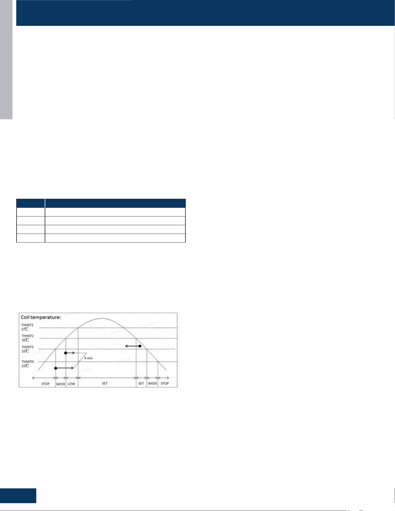
5. Whenthecoiltemperaturedrops,thefanspeedisjudged
accordingtothehotcrosstemperature:
• Coiltemperatureishigherthan35°C,fanspeedaccordingto
thesetoperation.
• Coiltemperaturebetween37°Cand35°Cfanspeedismid
• Coiltemperaturebetween35°Cand25°Cfanspeedislow
• Coiltemperaturebetween25°Cand23°Cfanspeedisweak
• Thefanstopswhenthecoiltemperatureislowerthan23°C
Residualheatsending:theindoorfanwilloperateonlowspeeduntil
thecoiltemperaturereaches73°Forstopafter50seconds.
Theoutdoorunittemperaturesensors:outdoorambient,defrost,
suctionline,andcompressordischarge,usedinconjunctionwiththe
indoorcoilandroomtemperaturesensors,provideinformationto
theoutdoorcontrolboardtomonitorthesystemandregulatethe
speedofthecompressor,theEEVandoutdoorfanspeedtoachieve
thedesiredroomtemperature.
Whenheatinghasbeensatised,thecompressorwillturnorst,
followedbytheoutdoorfan.The4-wayvalvewillde-energize2
minutesaftercompressorstops.
Tosaveenergy,Theindoorunitfanwillcontinuetorunatminimum
speeduntilindoorcoiltemperaturereachesaminimumtemperature,
whenitwillturno.
Ifthesystemdetectsamalfunction,itmayshutdownorshowan
errorcodeontheindoorunitdisplayboardand/orIoutdoorunitmain
boardLED.
Defrost
Whenthesysteminitiatesacallfordefrost,theindoorfanmotor
stops.Theindoorunitdisplaywillnotchange.Anyindoorunit
malfunctionswillbeignoredatthistime.Thesystemwillcycle
throughthedefrostoperation.Anyindoorunitmalfunctionswillbe
ignoreduntilthecompressorrestartsandhasbeenoperatingfor30
seconds.Attheconclusionofthedefrostcycle,theindoorfanwill
enterthecoldairproofoperation.Heatmoderesumes.
Automatic Heating Temperature Compensation
Whenthesystemisinheatingmode,atemperaturecompensation
adjustmentisaddedtothesensedtemperature.Thisisintendedto
adaptfortemperaturestraticationintheconditionedenvironment
relativetotheinstallationlocationoftheindoorhead.
Indoor Unit
Toentertheheatmode,pointtheinfraredremotecontrolleratthe
indoorunitandpressthepowerbutton,thenpresstheHEATmode
buttonifnotalreadysettoheatmode.
Thesignalsreceivedbytheinfraredreceiverarerelayedtothemain
boardoftheindoorunittoturnthesystemonandsetittoheat
mode.
TheindoorunitPCBwillactivatethedisplayoftheindoorunit,
illuminatingthedisplayandindicatingthesettemperatureand
currentstatusoftheunit.
TheindoorunitPCBwillsignalthesteppermotortoopenthelouver
toastationaryposition.
ThePCBwillpoweruptheindoorfanmotoraftertheoutdoorunit
hasstartedandheatingoftheindoorcoilhastakenplace(seecoldair
proofoperation).Themotorhasafeed-backcircuitwhichprovides
informationforcontrollingthespeedofthefanmotor.
Therewillbea3minutesdelaywhenswitchingfromhighspeedfanto
lowspeedfan.Therewillbenodelaywhenswitchingfromlowspeed
fantohighspeedfan.
Cold Air Proof Operation
Atinitialstartofheatmode,indoorblowerwillnotbeturnedon
immediatelyuntilindoorcoiltemperaturesensesaminimum
temperature.Thispreventscoldairfrombeingblownuntilthecoilis
heated.
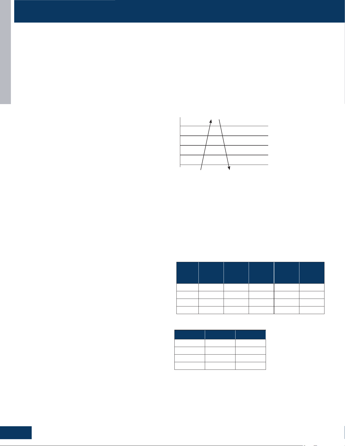
FanSpeed AmbientIndoorAirTemperature
Stop 8.8°Fandhigherabovesetpoint
Low Between5.9°Fand8.7°Fabovesetpoint
Medium Between3.6°Fand5.8°Fabovesetpoint
High Belowsetpointandupto3.5°Fabovesetpoint
Theindoorfaniscontrolledbasedonthecoiltemperature,asshown
inthegureabove.
Whenthecoiltemperaturerises,thefanspeedisjudgedaccordingto
thecoiltemperature:
1. Attheendofheatingordefrostingaftertherstpoweron,the
fanstopswhenthecoiltemperatureislowerthan25°C/77°F;
2. Coiltemperaturebetween25°C/77°Fand35°C/96°Ffanspeed
isweak;
3. Coiltemperaturebetween35°C/96°Fand37°C/100°Ffanspeed
isweak;
4. Coiltemperatureishigherthan37°C/100°F,fanspeedaccording

INTRODUCTION
A7
ENGLISH
FUNCTIONS AND CONTROL
Temperature Sensors
Theindoorunithastwosensorsthatprovidetemperature
informationtotheindoorunitmainboard.Thesensors:aroom
temperaturesensor,andpipetemperaturesensor,areusedfor
controllingthesystemduringheatmode.
Theresistancevaluesofthesensorswillvarywithtemperature.The
resistancetotemperaturevaluescanbefoundusingatemperature/
resistancechartspecictothesensorbeingchecked.
Communication
Theindoorandoutdoorunitmainboardscommunicateviaadigital
signalonthewireconnectedtoterminal3ofeachunit.Aspliceor
breakinthiswirewillcauseacommunicationerror.
Whenacommandisreceivedfromtheremotecontrol,theindoor
unitmainboardcommunicateswiththeoutdoorunittoperformthe
requestedfunction.
Outdoor Unit
Uponarequestforheat,theoutdoorunitPCBappliespowertothe
4-wayvalve,outdoorfanmotor,andcompressor.Dependingon
systemcycling,theremaybeuptoa3minutewaitperiodbeforethe
compressorandoutdoorfanstart.
NOTE: Do not measure compressor voltages as damage to the meter
may result.
Iftheroomtemperatureisabovethesettemperature,yetlowerthan
2°Fabovethesettemperature,thesystemwilladjusttherunning
frequencyofthecompressorautomatically.
TheoutdoorunitmainboardalsocontrolsthepositionoftheEEV
(ElectronicExpansionValve)toregulatetheowofrefrigeranttothe
outdoorunitevaporatorcoil.
Temperature Sensors
Fourtemperaturesensorslocatedintheoutdoorunitprovide
temperatureinformationtothePCBforcontrolofthesystemduring
heatmode.
Theambienttemperaturesensorprovidesthetemperatureoftheair
drawnintothecondensercoil.
Thedefrosttemperaturesensorprovidesthetemperaturesensedat
theoutputofthecondensercoil.
Thesuctionlinetemperaturesensorprovidesthetemperature
sensedattheincomingsuctionlinepipe.
Thecompressordischargesensorprovidesthetemperaturesensed
atthedischargepipeofthecompressor.
Call to Terminate Heating
Thesystemwillcalltoterminateheatingwhentheindoor
temperatureisequaltoorhigherthan2°Fabovetheroomset
temperature.Theindoorcontrolboardwillcommunicatetothe
outdoorcontrolboardtode-energizethecompressor.Theoutdoor
fanwillrunfor60secondsbeforestopping.The4-wayvalvewillde-
energize2minutesafterthecompressorstops.
Tostopheatmode,pressthepowerbuttontoturnthesystemo,or
changetoanothermode.
Auto Mode
Withthesystemturnedon,presstheAUTObuttonontheremote
control.Thesystemwillchangetotheautomodeofoperation.
Astheroomiscooledorheated,thesystemwillautomaticallyswitch
betweencoolmode,fanmode,andheatmode.Thereisaminimum
15minuteoperatingtimebetweenmodechanges.
Dry Mode
Overview
Thetemperaturecontrolrangeis60°F-86°F.Thismodeisusedfor
dehumidication.
Tr=roomtemperatureTs=settemperature
WhenTr>Ts+4°F,thecompressorwillturnonandtheindoorfanwill
operateatthesetspeed.
WhenTs≤Tr≤Ts+4°F,thecompressorwilloperateatthehighdry
frequencyfor10minutes,thenatthelowdrymodefor6minutes.
Theindoorfanwilloperateatlowspeed.
WhenTr<Ts,theoutdoorunitwillstop,andtheindoorfanwillstopfor
3minutes,thenoperateatthelowspeedoption.
Automaticfanspeed:
• WhenTr>Ts+9°F,Highspeed
• WhenTs+5.4°F≤Tr<Ts+9°F,Mediumspeed
• WhenTs+3.6°F≤Tr<Ts+5.4°F,Lowspeed
• WhenTr<Ts+3.6°F,Lightspeed
Note: TURBO and QUIET mode must be set using the remote controller.
Iftheoutdoorfanisstopped,theindoorfanwillpausefor3minutes.
Iftheoutdoorfanisstoppedformorethan3minutes,andthe
compressorisstilloperating,thesystemwillchangetolightspeed
mode.
Indoor Unit
Toenterthedrymode,pointtheinfraredremotecontrolatthe
indoorunitandpressthepowerbutton,thenpresstheDRYmode
buttonifnotalreadysettodrymode.
Thesignalsreceivedbytheinfraredreceiverarerelayedtothemain
boardoftheindoorunittoturnthesystemonandsetittodrymode.
Theindoorunitmainboardwillilluminatethedisplay,indicatingthe
settemperatureandcurrentstatusoftheunit.
ThePCBwillthensignalthelouversteppermotortoopenthelouver
toeitherastationaryposition,oroneofseveraloscillatingmodes.
Asthelouveropens,theindoorfanmotorwilloperateatthespeed
lastset.Thefanmotorhasafeedbackcircuitwhichprovidesthe
mainboardwithinformationforcontrollingthespeedofthefan
motor.
NOTE: It is recommended that Dry mode is not used for longer than a
4-hour period to minimize overflowing the condensate drain pipe.
Temperature Sensors
Theindoorunithastwosensorsthatprovidetemperature
informationtothePCB.Anambienttemperaturesensorandpipe
temperaturesensorareusedforcontrollingthesystemduring
drymode.Theresistancevaluesofthesensorswillvarywith
temperature.Theresistancetotemperaturevaluescanbefound
usingatemperature/resistancechartspecictothesensorbeing
checked.
INTRODUCTION
A8
ENGLISH
Protection Functions
Thesefunctionslimittheoperationofthesystemwhen
encounteringthenormaloperatinglimitsoftheequipment.
Compressor High Temperature
Thecompressordischargepipesensor(exhausttemp)sensesthe
temperatureoftherefrigerantexitingthecompressorThesensed
temperaturereceivedfromthesensorbythecontrolcircuitrywill
causethecompressorfrequencytoincreaseordecrease(seechart
below)Ifatemperatureof>=230°Fissensedfor2seconds,an
exhaustoverheatingprotectionerrorcodewillbeindicatedatthe
outdoor unit.
FUNCTIONS AND CONTROL
TTC
230°F
Abnormalstop
Decreasingfrequencyrapidly(1HZ/1second)
Decreasingfrequencyslowly(1HZ/10seconds)
Thefrequencydoesn’tchange
Increasingfrequencyslowly(1HZ/10seconds)
Normal
208.4°F
215.6°F
203°F
197.6°F
Overheating Protection for Indoor Unit
Asensormonitorscoiltemperatureinbothheatingandcooling
modes,andcausesthecompressortospeedup,slowdown,orstop.
Compressor Over-Current Protection
Ifthecurrentdrawofthecompressoratstartupisgreaterthanthe
valueslistedonthechartbelowforapproximately5seconds,the
compressorwillstop.After3minutesthecompressorwillrestart.If
theover-currentconditionoccurs3timesin20minutes,thesystem
willlock-out,andacodewillbeindicatedattheoutdoorunit.Itwill
benecessarytoremovepowertothesystemtoresetthelock-out
condition.
Model
Cooling
Increase
Point
Cooling
Decrease
Point
Heating
Increase
Point
Heating
Decrease
Point StopPoint
09K 5.5A 6.5A 7A 8A 10.5A
12K 5.5A 6.5A 7A 8A 10.5A
18K 12A 12A 13A 13A 14A
24K 14A 15A 14A 15A 16A
Model Cooling Heating
09K
15-71Hz 20-102Hz
12K 15-81Hz 20-102Hz
18K 13-48Hz 13-81Hz
24K 15-75Hz 20-105Hz
Communication
Theindoorandoutdoorunitmainboardscommunicateviaadigital
signalonthewireconnectedtoterminal3ofeachunit.Aspliceor
breakinthiswirewillcauseacommunicationerror.
Whenacommandisreceivedfromtheremotecontrol,theindoor
unitmainboardcommunicateswiththeoutdoorunitmainboardvia
theterminal3wiretoperformtherequestedfunction.
Outdoor Unit
Uponarequestfordrymode,theoutdoorunitmainboardapplies
powertothefanmotorandcompressor.Dependingonsystem
cycling,theremaybeuptoa3minutewaitperiodbeforethe
compressorandoutdoorfanstart.
WARNING:Donotmeasurecompressorvoltages,damagetothe
metermayresult.
TheoutdoorunitPCBalsocontrolsthepositionoftheEEV
(ElectronicExpansionValve}toregulatetheowofrefrigeranttothe
indoorunitevaporatorcoil.
Temperature Sensors
Fourtemperaturesensorslocatedintheoutdoorunitprovide
informationtotheoutdoorunitPCBforcontrolofthesystemduring
dry mode.
Theoutdoorambienttemperaturesensorprovidesthetemperature
oftheairdrawnintothecondensercoil.
Thedefrosttemperaturesensorprovidesthetemperaturesensedat
theoutputofthecondensercoil.
Thesuctionlinetemperaturesensorprovidesthetemperature
sensedattheincomingsuctionlinepipe.
Thecompressordischargesensorprovidesthetemperaturesensed
atthedischargepipeofthecompressor.
Tostopdrymode,pressthepowerbuttontoturnthesystemo,or
changetoanothermode.
Defrost Operation
Toenterthedefrostmode,thecompressormusthaveaccumulated
10minutesofruntime,and45minutesofaccumulatedruntime
sincethelastdefrostcycle.
Whenthedefrostcyclebegins,thefollowingconditionstakeplace:
1. Indoorfanmotorstops.
2. Compressorstopsfor40seconds.
3. After40seconds,the4-wayvalveshiftstocoolingpositionand
outdoorfanstops.Compressorstartagain.
4. About1minute,thecompressoracceleratestothedefrost
frequency.
5. Theoutdoorunitwillnowdefrost.Defrostcycleruns
continuouslyforapproximately10minutes,unlessthe
condensermaintainsatemperatureabove48°Ffor60seconds,
orthecondensermaintainsatemperatureabove59°Ffor5
seconds.
Uponexitingthedefrostcycle,thefollowingconditionswilltake
place:
1. Thecompressorwillstop.
2. Theoutdoorfanwilloperateathighspeed.
3. 25secondslaterthe4-wayvalvewillshifttotheheatingmode.
4. 30secondslaterthecompressorwillstart,andthesystem
resumesnormaloperation.
Compressorfrequencies:
INTRODUCTION
A9
ENGLISH
FUNCTIONS AND CONTROL
OutdoorTemperature PanHeater
>37°F(3°C) OFF
28°F(-2°C)to34°F(1°C) OFF20min,ON10min
10°F(-12°C)to25°F(-4°C) OFF15min,ON15min
<10°F(-12°C) ON
Indoor Coil Anti-Freeze Protection
Thetemperaturesensedbythecoilsensorisusedtodetermineat
whatspeedthecompressoristoruntoavoidthecoiltemperature
beingtoocold.
TCI_Indoor:Indoorunitpipesensortemperature
tS:OutdoorunitSuctionLinesensortemperature
• WhenMin(TCI_indoor,(TCI_indoor+tS)/2)<TCI1,thefrequency
ofthecompressordecreasesattherateof1HZ/1second.
• WhenMin(TCI_indoor,(TCI_indoor+tS)/2)<TCI2,thefrequency
ofthecompressordecreasesattherateof1HZ/10second.
• WhenTCI_indoorbeginstoriseagain,andTCI2≤Min(TCI_indoor,
(TCI_indoor+tS)/2)≤TCI3,thefrequencyofthecompressor
doesnotchange.
• WhenTCI3<Min(TCI_indoor,(TCI_indoor+tS)/2)<TCI4,the
frequencyofthecompressorincreasesattherateof1HZ/10
second.
Example:ifMin(TCI_indoor,TCI_indoor+tS)/2)≤32°Fsustains
for2minutes,theoutdoorunitwillstopandindicateanunderload
malfunctioncodeattheoutdoorunit.Thecompressorstopsfora
minimumof3minutes.WhenMin(TCI_indoor,TCI_indoor+tS)/2)>
TCI4,thecompressorwillrestart.
Base Pan Heater
Tokeepcondensatewaterfromfreezinginsidethecabinet,abase
panheaterisinstalledatthefactory.
Operationcondition:
A.Itwillstartwhiledefrostingprocessisrunning.
B.IfACisnotindefrostprocess,itwillworkrefertothechart
belowfortheoperatingparameters.
52°F
46°F
Decreasingslowly
Decreasingrapidly
Stop
Keepingfrequency
Increasesslowly
Tpg4=48°F
Tpg3=45°F
Tpg2=41°F
3Tpg1=7°F
32°F
Special Functions
Auto Restart
Whenthisisenabled,thefollowingfunctionswillautomatically
resumesafterapowerloss:
• ON/OFFState,ModeofOperation,FanSpeed,Temperature
Setpoint,LouverSwingsettings.
• Iftherewasatimerset,itwillbecanceleduponrestart.
Forced Defrost
ViaRemoteController
Settingmethod:
1. SettoHEATMode
2. Setto30°C/86°F
3. SetHighFanSpeed
4. PressTemperature+Button10timeswithin7seconds
5. UnitwillBeep7timestoConrm.
Cancelmethod:
SameprocessasSettingMethod.HearUnitBeep5timestoconrm
ofcancelfunction.
Indoor Temperature Display
Thisfunctionwillallowyoutosetthedisplaytoshoweitherthe
Ambienttemperatureorthesetpoint:
Settemperature:
• PresstheLightbutton10timeswithin5second.UnitwillBeep4
timestoconrm.
Ambienttemperature:
• PresstheLightbutton10timeswithin5second.UnitwillBeep2
timestoconrm.
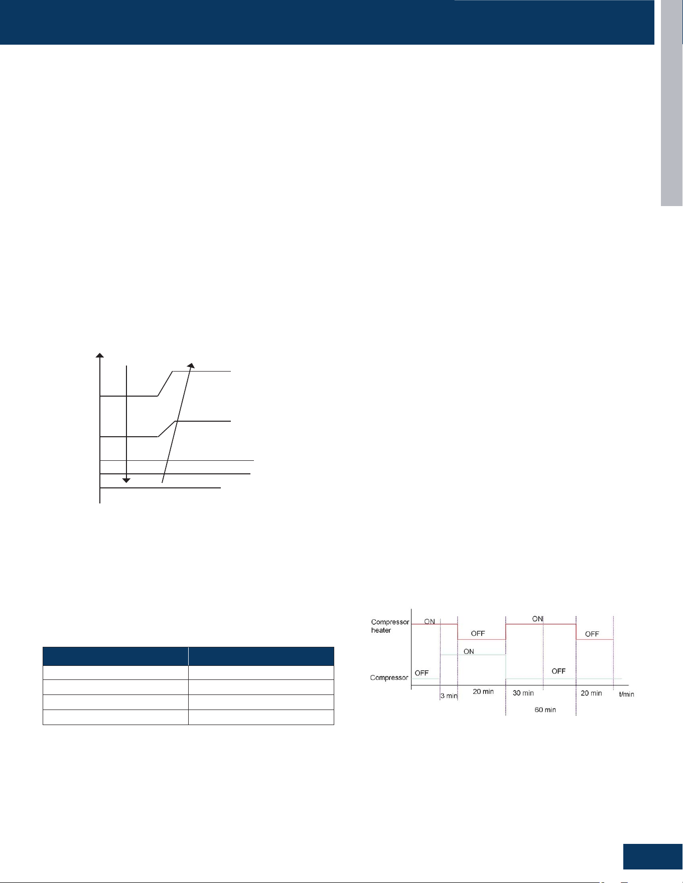
Crankcase (Compressor) Heater
Operationlogic:
A.Ifoutdoorambienttemperatureis5°C,compressorheateris
OFF.
B.Ifoutdoorambienttemperatureis<3°C,compressorheater
functionsasshown:
INTRODUCTION
A10
ENGLISH
FUNCTIONS AND CONTROL
Temperature Compensation
SetTemperature:
1. Applypowertotheunit.
2. SettoCoolingModeorHeatingMode
3. Setthetemperatureto24°C(75°F).
4. PresstheSLEEPbutton7timeswithin5seconds.IndoorPCBwillbeep2timestoconrm.
5. 24°Cwillbethestarting/referencepointfortheTemperatureCompensation.
6. Press or onthecontrollertoadjustcompensationtemperaturevalue.TemperatureCompensationcanbeadjustedfrom-8°Cto
+6°C.(Example:ifyouwanttosettheTemperatureCompensationvalueby4°C,thensetthetemperatureto28°C.)
7. Oncethedesiredvaluehasbeenselected,turnOFFtheunittosavethecompensationsettings.
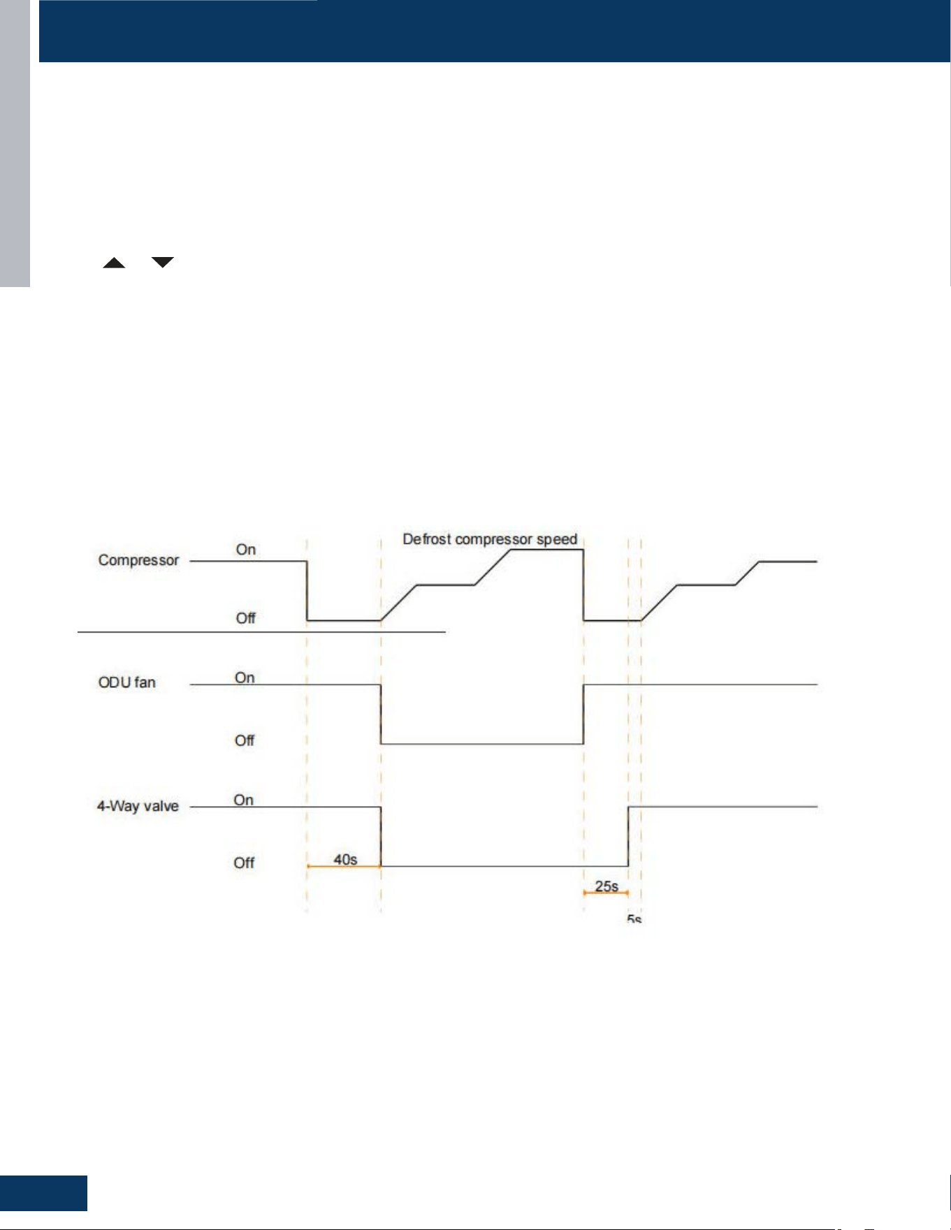
Timed Defrost
Logic:
1. Afterreceivingthedefrostsignal,thecompressorwillstop.
2. 40secondslater,thefour-wayvalveisreversedandtheoutdoorfanstops.
3. Thecompressorgraduallyincreasesfrequencytothehighestdefrostingfrequency.
4. Afterdefrostingcompletes,theoutdoorfanmotorstarts,thecompressorstop,andthefour-wayvalveisopenedafter25seconds
5. Thecompressorwillstartafter5seconds.
ENGLISH
OUTDOOR UNITS
B1
OUTDOOR UNITS
COMPONENTS .......................................................................................................................................................................B2
OutdoorComponentIdentication ......................................................................................................................................B2
TerminalBlock ......................................................................................................................................................................... B3
PowerFactorReactor .............................................................................................................................................................B3
Compressor ............................................................................................................................................................................B3
FanMotor ................................................................................................................................................................................B3
TemperatureSensors ............................................................................................................................................................. B4
4-WayValve .............................................................................................................................................................................B4
ElectronicExpansionValve ....................................................................................................................................................B4
Accumulator ............................................................................................................................................................................B5
RefrigerantStrainers ..............................................................................................................................................................B5
CompressorHeater ................................................................................................................................................................B5
OutdoorUnitControlBoard ..................................................................................................................................................B6
WIRING DIAGRAM ................................................................................................................................................................... B8
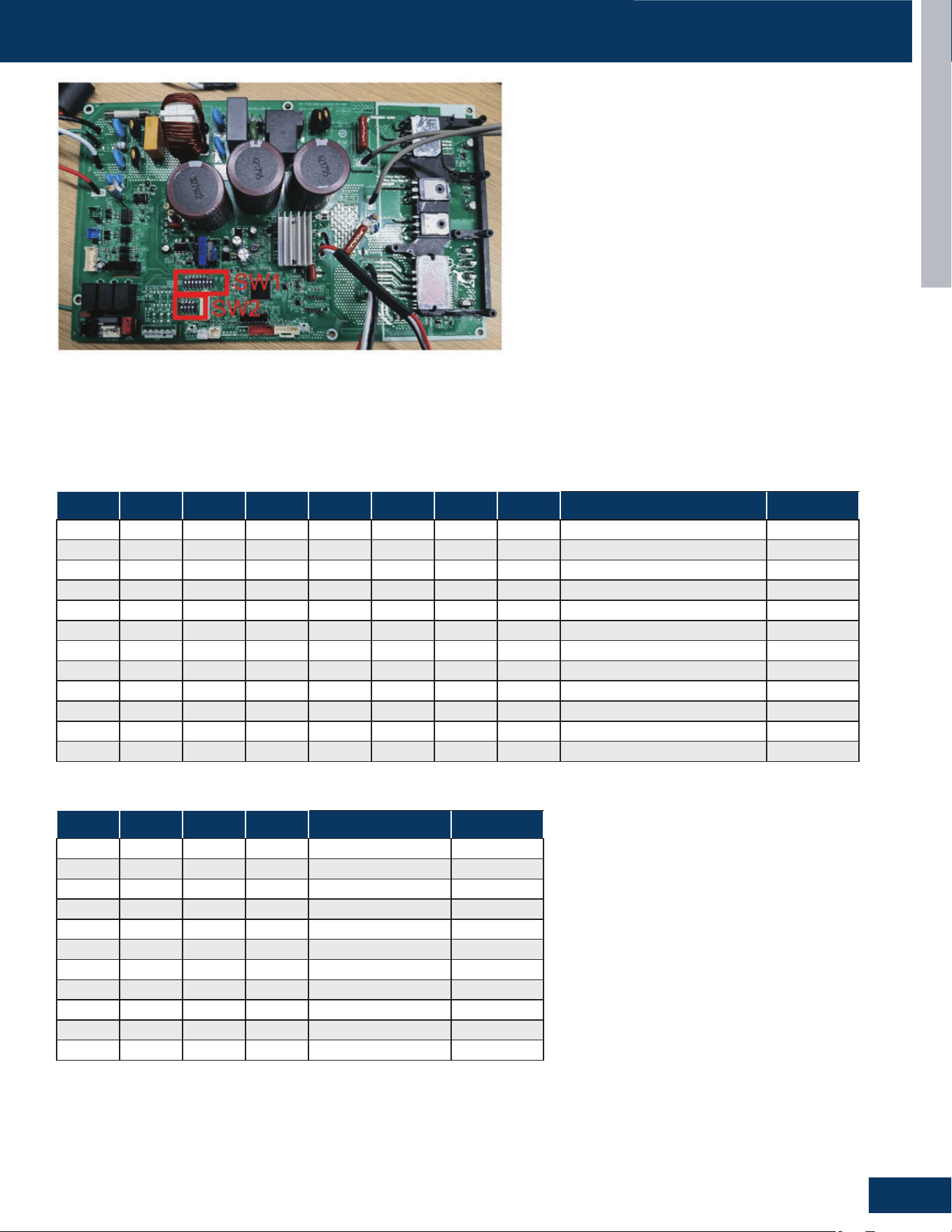
DIP SWITCH SETTINGS
..........................................................................................................................................................B9
SERVICE PROCEDURES
........................................................................................................................................................B10
CheckingtheOutdoorUnitSensors ...................................................................................................................................B10
CheckingtheReversingValveCoil ....................................................................................................................................... B10
CheckingtheCompressorWindings ................................................................................................................................... B10
CheckingtheEEVCoil ..........................................................................................................................................................B10
CheckingtheOutdoorDCFanmotor .................................................................................................................................B10
CheckingtheCompressorHeater .......................................................................................................................................B11
CheckingtheReactor ...........................................................................................................................................................B11
TABLE OF CONTENTS
1G09CB2BEA
1G12CB2BEA
1G18CB2BEA
1G24 CB2BEA
ENGLISH
OUTDOOR UNITS
B2
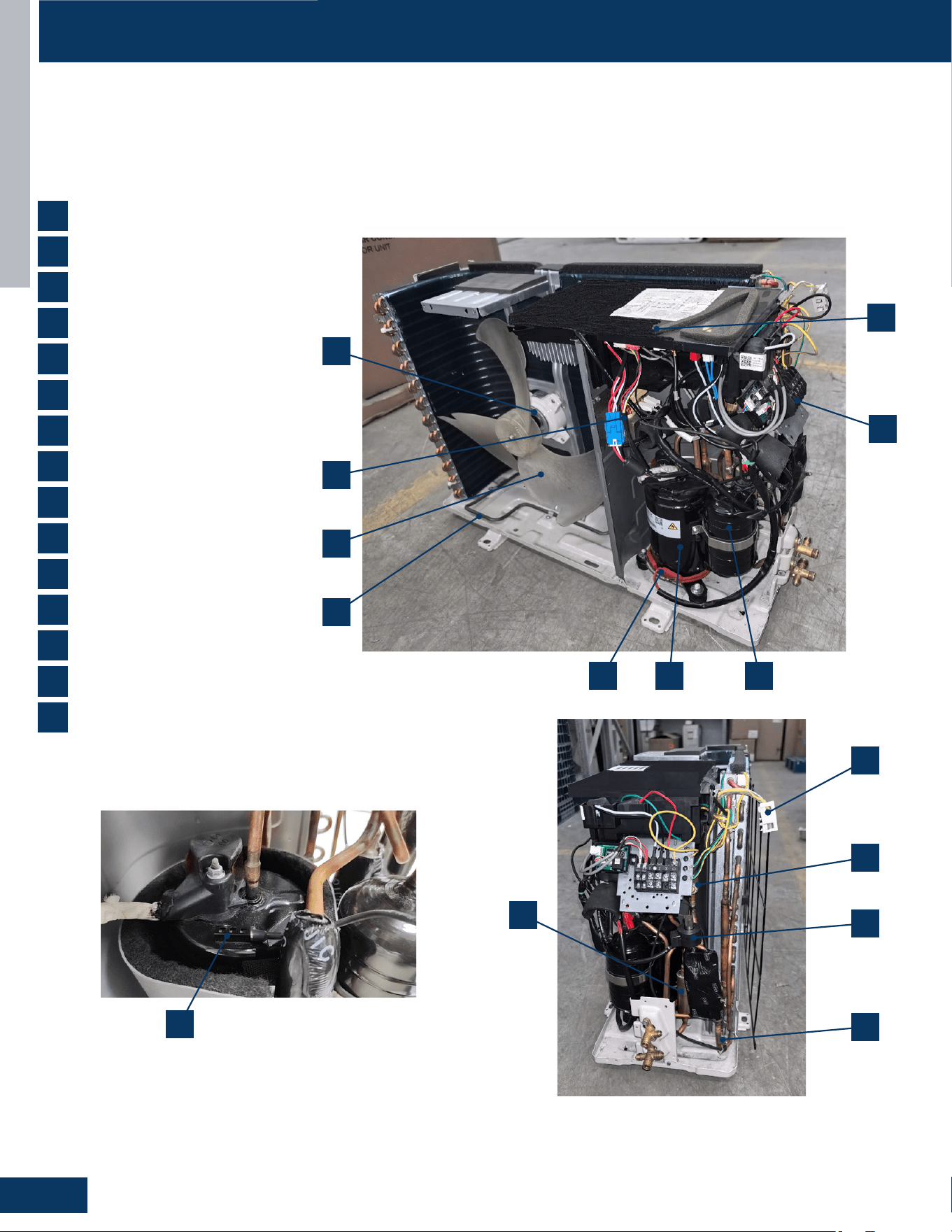
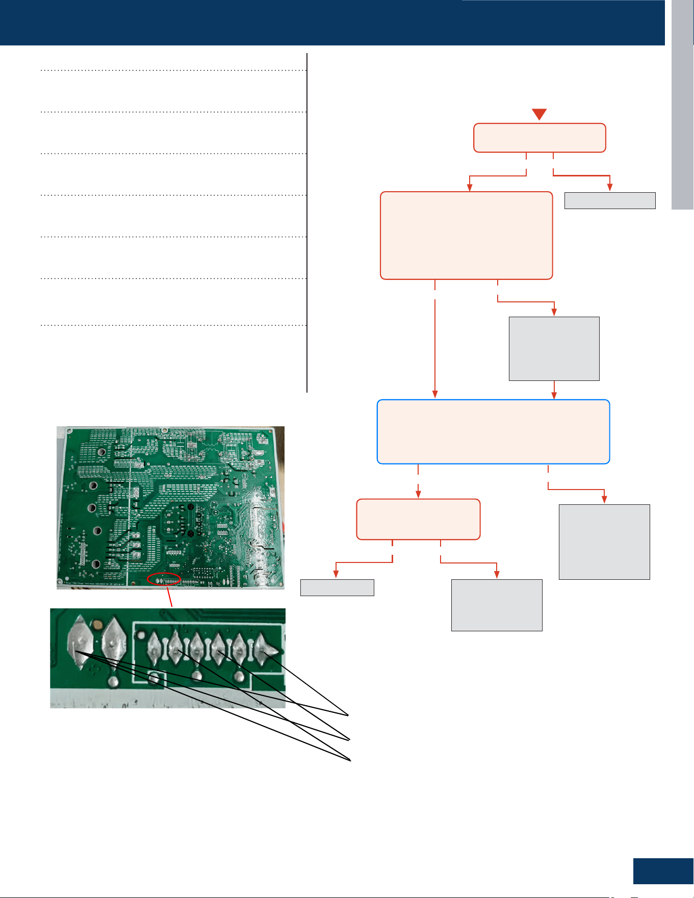
COMPONENTS
TheoutdoorunithasaPCBthatintegratesthecontrolfunctionsandpowerfunctionsintoonePCB.Sensorsmonitorkeytemperatures
throughoutthesystemtomanageoperationaldecisions.
4-WayValve
Accumulator
Compressor
DefrostTemperatureSensor
DischargeTemperatureSensor
ElectronicExpansionValve
RefrigerantStrainers
AmbientTemperatureSensor
FanMotor
PowerFactorReactor
TerminalBlock
PowerControlBoard(PCB)
FanBlade
CompressorHeater
BasePanHeater
1
2
3
4
5
6
7
8
9
10
11
12
13
14
15
Outdoor Component Identication
14
13
10
9
15
12
6
1
11
23
7
4
5
8
ENGLISH
OUTDOOR UNITS
B3
TheReactorisapowerlter.Itisunlikelytoeverhaveanelectrical
failureofthiscomponent.
TheReactorofalloutdoorunitsiselectricallyconnectedtotheIPM
onterminalconnectionsCN-5andCN-6.
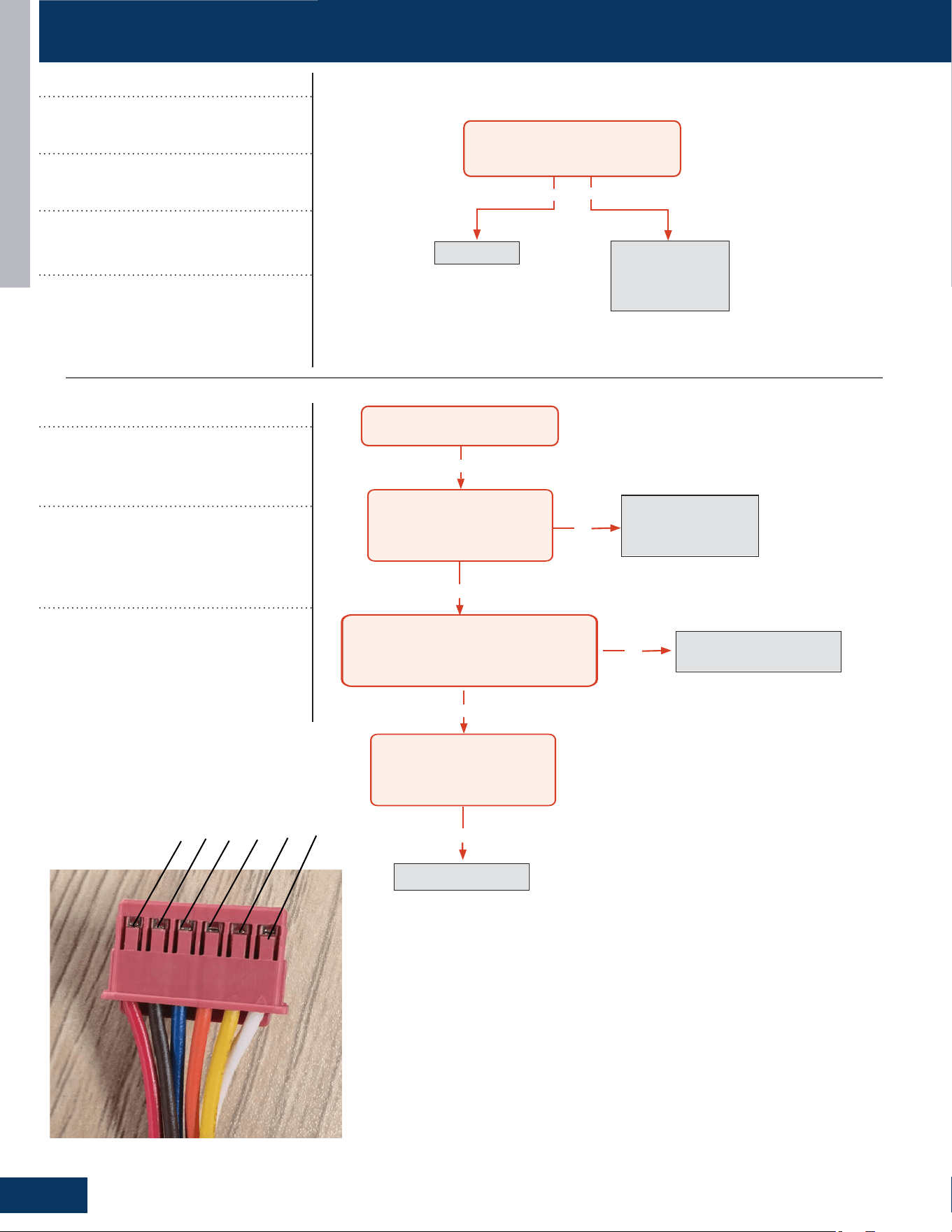
Theoutdoorunitispoweredby208/230voltsinglephaseelectricity
connectedattheterminalblock.
Terminals1and2connectthisvoltagetothesystem.
Thenumber3terminaliscommunicationthatconnectswiring
betweentheindoorandoutdoorunits.Agroundterminalconnects
theoutdoorunittothelinevoltagepowersource.
Theindoorunitisalsopoweredbythesameelectricalsupplyas
theoutdoorunit.OnlyAWG14-4strandedcopperwireisallowed
connectedtotheTerminalBlockblockattheoutdoorunitandisrun
tothesameterminalsontheindoorterminalblock.
Wheninstallingtheeldsuppliedwiring,makecertainthewiregauge
iscorrect.Thereshouldnotbeanyelectricalwiringsplicesbetween
theindoorunitandoutdoorunitwireconnection3.Thiswireis
usedtocarrycommunicationdatabetweentheindoorandoutdoor
units.Awiringsplicewherewiresaretwistedinawirenutmaycause
deformationofthecommunicationsignal.Ifcommunicationislost
betweentheindoorandoutdoorunits,anERRORCODEE7willoccur.
ThefanmotorisavariablespeedDCmotor.Therequiredspeedis
calculatedbythePCB.ThemotoriselectricallyconnectedtothePCB
viaPLUGCN-10.
Incoolmode,themotorwillslowdownasoutdoorairtemperature
falls.
Inheatmode,themotorwillincreasespeedastheoutdoorair
temperaturefalls.
ThecompressorisathreephaseDCinverterdrivenrotarytype,
capableofvariablespeedoperation.Thecompressoroperating
frequencywillbedeterminedbythetemperaturedierencebetween
setpointandroomtemperature.
Thecompressorofalloutdoorunitsiselectricallyconnectedtothe
IPMonterminalconnectionsCN-7,CN-8andCN-9.
Protectionofthecompressorwillbeprovidedbythedischarge
temperaturesensor,thesuctionlinetemperaturesensor,andthe
overcurrentprotectionparameterinthePCB.
Terminal Block Compressor
Fan MotorPower Factor Reactor
COMPONENTS
ENGLISH
OUTDOOR UNITS
B4
COMPONENTS
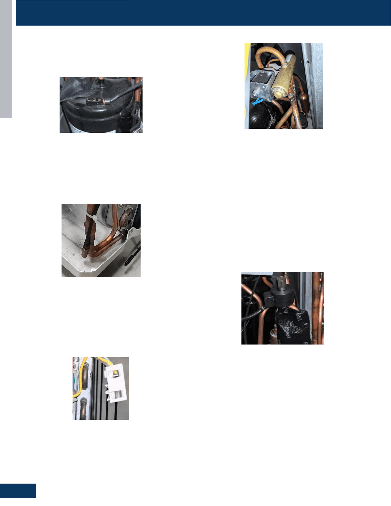
Temperature Sensors
TheDischargeTemperatureSensorisanegativecoecient
thermistorthatsensesthetemperatureofthecompressorhot
gas.ThePCBmonitorsthetemperatureofthecompressorhotgas
andwillmakeinverterspeedchangesinresponsetoinputfromthis
device.
ThissensorconnectstotheMainControlBoardatPLUGCN-15
These3sensorsarepartofanassemblyandwillallbechanged
together:
Defrost Temperature Sensor
Defrost Temperature Sensor
TheDefrostTemperatureSensorisanegativecoecientthermistor
thatwillchangeresistanceinresponsetooutdoorcoiltemperature
changes.ThePCBmonitorsthetemperatureoftheoutdoorcoilto
determinewhenthesystemshouldperformadefrostcycle.The
sensoralsomonitorscoiltemperatureduringdefrostcyclesto
determineterminationconditions.
ThissensorconnectstothePowerControlBoardatPLUGCN-15.
Outdoor Ambient Temperature Sensor
TheAmbientTemperatureSensorisanegativecoecient
thermistorthatwillchangeresistanceinresponsetooutdoorair
temperaturechanges.ThePCBmonitorsthetemperatureofthe
outdoorairtodeterminefanspeedrequirementsandinverter
speed.Thesensoralsoplaysaroleincalculationofrequireddefrost
conditions.
ThissensorconnectstothePowerControlBoardatPLUGCN-15
4-Way Valve
The4-WayValveredirectstheowofrefrigerantinthepipingcircuit
toallowthesystemtoreversethefunctionsoftheindoorand
outdoorcoils.Whende-energizedinCOOLMODE,thevalvewill
directtherefrigeranthotgastotheoutdoorcoil.Whenenergizedin
HEATMODE,thevalvewilldirectthehotgastotheindoorcoil.
Thevalveowdirectioncapabilityiscontrolledbyanelectrical
solenoid.Whenenergizedwith208/230VAC,thesolenoidwill
magneticallymoveaninternalslidewithinthe4-WayValvetochange
thedirectionofrefrigerantow.
The4-WayValveiselectricallyconnectedtothePowerControlBoard
atPLUGCN-11.
Electronic Expansion Valve
Themeteringdeviceisanelectronicexpansionvalve.Thevalve
consistsofanelectricaloperatorandavalvebodywithinternal
variablesizeorice.Whenoperating,thePCBwillsendpulsesof
voltagetotheelectricaloperator.Theoperatorwillthenmagnetically
movethepositionofthemeteringoricepintovaryrefrigerantow.
Themeteringdevicepositionisdeterminedbyinputfroma
DischargeTemperatureSensor.TheEEVwillchangetheinternal
oricesizetomaintainanacceptablelevelofsuperheat.
DuringCOOLMODEthevalvemeterslowpressurerefrigerantto
theindoorcoil.DuringHEATMODEthevalvemeterslowpressure
refrigeranttotheoutdoorcoil.
TheelectricalexpansionvalveiselectricallyconnectedtothePower
ControlBoardatPLUGCN-16.
ENGLISH
OUTDOOR UNITS
B5
COMPONENTS
Refrigerant Strainers
Thesystemhasdebris-catchingstrainersthatprotectinternal
systemcomponentsfromcontaminantsintherefrigerant.The
strainerisapermanentpartthatisnottypicallyreplaced.
Accumulator
TheAccumulatorislocatedinthesuctionlinecircuitatthe
entrancetothecompressor.Theaccumulatorhelpsprevent
liquidrefrigerantfromenteringthecompressorduringrun
operation.
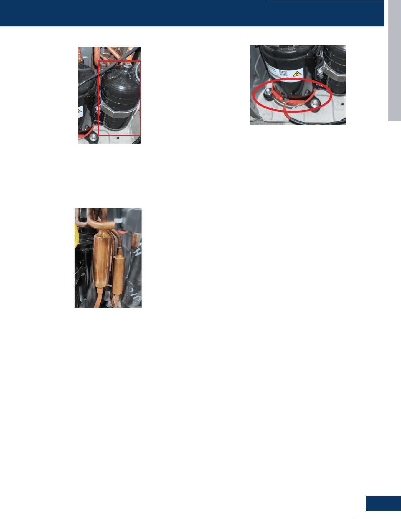
Compressor Heater
TheCompressorheaterisusedtopreheatthecompressorandassist
thestartofthecompressoratlowtemperature.TheCompressor
HeateriselectricallyconnectedtothePowerControlBoardatPLUG
CN-13andenergizedwith208/230VAC.
ENGLISH
OUTDOOR UNITS
B6
COMPONENTS
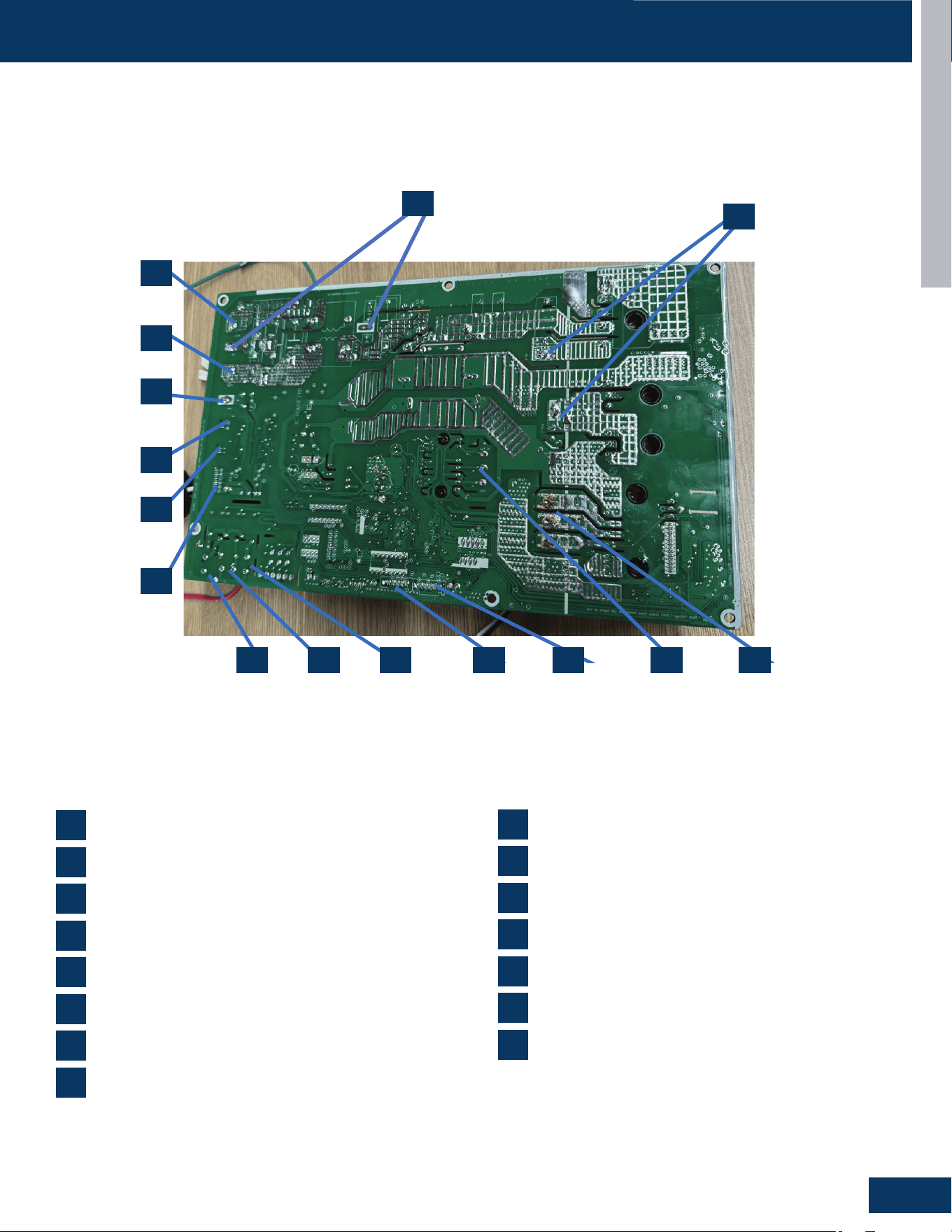
Outdoor Unit Control Board
2
CN3,CN30:ConnectorforGND
10
CN5,CN6:Connectorforthereactor
6
CN15:Connectionsfortemperaturesensors
4
CN10:Connectorforthefanmotor
12
CN19:ConnectorfortheRJ45
8
CN11:Connectorforfourwayvalvecoil
CN1:230VACpowerfromterminalblockconnectionsand1(L1)
1
CN16:Connectorfortheelectronicexpansionvalve
7
CN4:Communicationconnectionbetweentheindoorboard
andtheoutdoorboard
3
CN13:Connectorforthecompressorheater
11
CN12:Connectorforthebasepanheater
9
CN7,CN8,CN9:CompressorU,V,Wconnections
5
CN24:ConnectorfortheOTA
13
CN14:Connectorforthecentralizedcontroller
14
CN2:230VACpowerfromterminalblockconnectionsand
2(L2)
15
1
2
3
4 5679 8
10
11
12
13
14
15
ENGLISH
OUTDOOR UNITS
B7
COMPONENTS
2
CN3,CN30:ConnectorforGND
10
CN5,CN6:Connectorforthereactor
6
CN15:Connectionsfortemperaturesensors
4
CN10:Connectorforthefanmotor
12
CN19:ConnectorfortheRJ45
8
CN11:Connectorforfourwayvalvecoil
CN1:230VACpowerfromterminalblockconnectionsand1(L1)
1
CN16:Connectorfortheelectronicexpansionvalve
7
CN4:Communicationconnectionbetweentheindoorboard
andtheoutdoorboard
3
CN13:Connectorforthecompressorheater
11
CN12:Connectorforthebasepanheater
9
CN7,CN8,CN9:CompressorU,V,Wconnections
5
CN24:ConnectorfortheOTA
13
CN14:Connectorforthecentralizedcontroller
14
CN2:230VACpowerfromterminalblockconnectionsand
2(L2)
15
1
2
3
4 5679 8
10
11
12
13
14
15
ENGLISH
OUTDOOR UNITS
B8
WIRING DIAGRAM
1
2
3
5
6
7
9
3
9
2
31-5000931 Rev. 0
8
ENGLISH
OUTDOOR UNITS
B9
DIP SWITCH SETTINGS
SW1-1 SW1-2 SW1-3 SW1-4 SW1-5 SW1-6 SW1-7 SW1-8
Setting Description
OFF ---- ---- ---- ---- ---- ---- ----
ACLoopCommunications Default
ON ---- ---- ---- ---- ---- ---- ---- 24VCommunication
---- OFF ---- ---- ---- ---- ---- ---- CentralControllerProtocol Default
---- ON ---- ---- ---- ---- ---- ---- BMSProtocol
---- OFF OFF OFF OFF OFF OFF OFF CentralControllerAddress1 Default
---- OFF OFF OFF OFF OFF OFF ON CentralControllerAddress2
---- OFF ---- ---- ---- ---- ---- ---- --
---- OFF ON ON ON ON ON ON CentralControllerAddress64
---- ON OFF OFF OFF OFF OFF OFF BMSprotocolAddress1
---- ON OFF OFF OFF OFF OFF ON BMSprotocolAddress2
---- ON ---- ---- ---- OFF ---- ---- --
---- ON ON ON ON ON ON ON BMSControllerAddress64
SW2-1 SW2-2 SW2-3 SW2-4
Setting Description
OFF OFF ON ON
Caliber9K
OFF ON OFF OFF Caliber12K
OFF ON OFF ON Caliber15K
OFF ON ON OFF Caliber18K
OFF ON ON ON Caliber24K
ON OFF ON OFF Reserved
ON OFF ON ON Reserved
ON ON OFF OFF Reserved
ON ON OFF ON Reserved
ON ON ON OFF Reserved
ON ON ON ON Reserved
DIP SW1
DIP SW2
Purpose of Dip Switch Settings
AC Loop Communication: AC loop communication
setting make sure communication between the indoor
and outdoor units aims at communication between the
indoor and outdoor units
Central Controller: Enable system for compatibility with a
central controller. Currently, a 5-inch central controller is
available.
24V Communication: Enable system for use with a third-
party 24v controller
BMS Protocol Setting: With this setting, system can be
connected to building system.
ENGLISH
OUTDOOR UNITS
B10
SERVICE PROCEDURES
NOTE:Componentresistancereadingsshowninthissectionareforreferenceonly.Actualresistancevaluesmayvarybasedonmodelbeing
tested.
Testingofthefollowingcomponentsrequirestheuseofneedleprobes.Avoidtestingtheconnectorendoftheplug,asdamagetotheinternal
sectionsoftheplugcanoccur.
Checking the Outdoor Unit Sensors
NOTE:Userespectivetemperature/sensorchartforsensortype
beingtested.
• Compressordischargesensor
• Suction sensor
• Defrosttemperaturesensor
• Ambientsensor
Step 1
Disconnectthesensorplugfromthecontrolboardforthistest.
Failuretodosomayprovideinaccuratereadings.
Step 2
Usingk-typetemperatureprobe,determinethetemperatureofthe
sensorbeingtested.
Step 3
Usinganohmmeter,checktheresistancevalueofthesensor.
Step 4
Referringtothetemperature/resistancetableforthesensorbeing
checked,verifytheresistancevaluecorrespondstothetemperature
checkedinStep2.Replacethesensorifthereadingisopen,shorted,
or outside
Step 5
Re-seattheplugontheconnectorattheconclusionofthetest.
Checking the Compressor Windings
Step 1
DisconnectwiringfromterminalsU,VandWoftheIPM.
Step 2
UsinganOhmmeter,checktheresistancevalueofthecompressor
windings.MeasurebetweenwiresUandV,UandW,andV,andW.
Theresistancevalueofthewindingsshouldbebalanced(equal
+/-20%).Iftheresistancevaluesarenotequal,verifythewiringand
connectionstothecompressoraswellasthecompressoritself.
Repairorreplaceasneeded.
Step 3
ReconnectthewiringtotheIPMattheconclusionofthetest.
Checking the Outdoor DC Fan motor
Step 1
Initiateforcedcooling.
Step 2
Iftheoutdoorunitfanmotordoesnotrun,ortheServiceMonitor
Boardindicatesanerrorcodeof09,checkthefollowingvoltagesat
connectorCN11ontheoutdoorunitPCB.SetthemetertoreadDC
voltswithaminimumvoltagerangeof360volts(voltagevaluesare
approximate):
DCvoltagebetweentheRedandBlack,betweentheWhiteandBlack,
andbetweentheRedandWhitewiresshouldread310~334VDC.
Thisisthemainvoltageforpoweringthefanmotor.
Checking the Reversing Valve Coil
Step 1
DisconnectthereversingvalveplugfromthePCBforthistest.Failure
todosomayprovideinaccuratereadings.
Step 2
Usinganohmmeter,checktheresistancevalueofthecoil.The
resistancevalueofthecoilshouldbe1.2kiloohmsto1.8kiloohms.
Replacethevalvecoilifthereadingissignicantlydierent,orifthe
coilshowsopenorshorted.
Step 3
Re-seattheplugontheconnectorattheconclusionofthetest.
Iftheoutdoorfaninitiallyruns,increasesspeed,thenstops,andthe
ServiceMonitorBoardindicatesanerrorcodeof09,thefeedback
circuitisnotfunctioning.Checkthatthewiringandplugconnections
areingoodcondition.
Checking the EEV Coil
Step 1
DisconnecttheEEVcoilfromthePCBforthistest.Failuretodoso
mayprovideinaccuratereadings.
Step 2
Measuretheresistancebetween6
and4,6and2,5and3,5and1,andthe
resistance,betweenthemisroughlythe
same,alllessthan100Ohm.
Step 3
Re-seattheplugontheconnectoratthe
conclusionofthetest.

ENGLISH
OUTDOOR UNITS
B11
Checking the Compressor Heater
Useamultimetertomeasuretheresistanceatbothendsofthe
heatingwireharnessterminalofthecompressor.Theresistance
valueis2400±5%.
Checking the Reactor
Useamultimetertotesttheresistancebetweentwoterminalsofa
reactor.Themaximumresistanceis130mΩ.
SERVICE PROCEDURES
[This page intentionally left blank.]

HIGHWALL INDOOR UNITS
C1
ENGLISH
HIGHWALL INDOOR UNITS
COMPONENTS .......................................................................................................................................................................C2
IndoorComponentIdentication ..........................................................................................................................................C2
TerminalBlock .........................................................................................................................................................................C3
Display .....................................................................................................................................................................................C3
AmbientTemperatureSensor ...............................................................................................................................................C3
PipingTemperatureSensor ...................................................................................................................................................C3
LouverStepperMotor ............................................................................................................................................................C4
FanMotor ................................................................................................................................................................................C4
EmergencyButton ..................................................................................................................................................................C4
IndoorUnitControlBoard ......................................................................................................................................................C5
WIRING DIAGRAM ................................................................................................................................................................... C8
DIP SWITCH SETTINGS
..........................................................................................................................................................C9
SERVICE PROCEDURES
........................................................................................................................................................C10
CheckingtheIndoorUnitSensors ...................................................................................................................................... C10
CheckingtheStepperMotors ............................................................................................................................................. C10
TABLE OF CONTENTS
GS09WB2BEA
GS12WB2BEA
GS18WB2BEA
GS24WB2BEA
HIGHWALL INDOOR UNITS
C2
ENGLISH
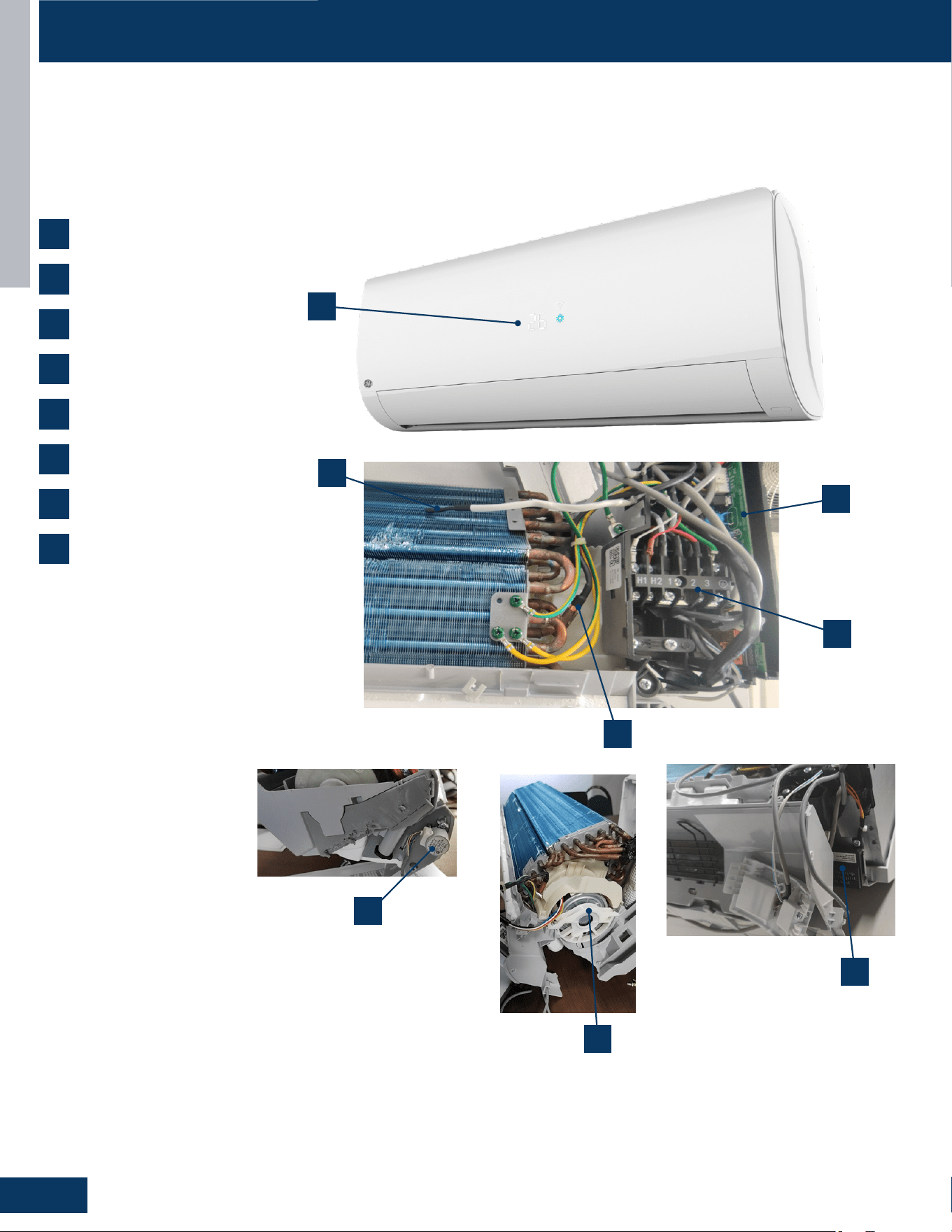
Indoor Component Identication
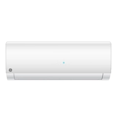
Theindoorunitismountedhighonthewalltoprovidecomfortandairmovementwithintheconditionedspace.Featuresofthesysteminclude:
Variablespeedbloweroperationthatspeedsupandslowsdownwithchangesindemand,movinglouverstodirectair,indoorairtemperature
sensing,evaporatorcoiltemperaturesensing,astatusdisplay,evaporatorcoilwithmeteringdevicelocatedinoutdoorunit,andanemergency
operationbutton.
COMPONENTS
AmbientTemperatureSensor
DisplayPanel
FanMotor
LouverMotors
PowerControlBoard(PCB)
PipingTemperatureSensor
TerminalBlock
R454BLeakagesensor
1
2
3
4
5
6
7
8
3
2
1
5
6
7
8
4
HIGHWALL INDOOR UNITS
C3
ENGLISH
COMPONENTS
Terminal Block
Ambient Temperature Sensor
Theunitterminalblockreceiveselectricalpowerfromtheoutdoor
unit.Thereare4connectionsforelectricalwires.Terminals1and2
areconnectedtoterminals1and2oftheoutdoorunit.Thiswiring
suppliespowertotheindoorunit.
Terminal3isacommunicationwire.Theindoorunitsendsindoorair
temperature,coiltemperatureandtemperaturesetpointinformation
totheoutdoorunitonthiswire.Ifaspliceorbreakinthiswireis
present,theindoorunitwillnotbeabletocommunicatewiththe
outdoorunit.TheERRORCODEwillbeanE7.
TheAmbient(room)TemperatureSensorisanegativecoecient
thermistorthatwilldecreaseinresistancewithincreasesinroomair
temperature.Thesensorislocatedonaclipmountedinthereturnair
stream.
ThesensorconnectstothecontrolboardatPlugCN-6.
Piping Temperature Sensor
ThePipingTemperatureSensorisanegativecoecientthermistor
thatwilldecreaseinresistancewithincreasesincoiltemperature.
Thesensorislocatedinasocketsolderedtothesurfaceofthe
indoorcoil.
Thissensorwillmonitorthetemperatureoftheindoorcoilinboth
coolingandheatingmodesofoperation.Shouldabnormallycoldor
hotcoiltemperaturebedetectedbythissensor,thesystemwilltake
stepstocorrecttheconditionorreportanERRORCODE.
ThesensorconnectstothecontrolboardatPlugCN-6.
Display
Theindoordisplayhasaninfraredcommunicationcircuitthat
receivesTheindoordisplayhasaninfraredcommunication
circuitthatreceivesoperatingcommandsfromtheremote
control.Thisdisplaywillindicateoperatingmodes,error
codes,indoorairtemperature,timerstatus,andpower
status.
ThedisplayboardconnectstothecontrolboardatPlugCN-7.
HIGHWALL INDOOR UNITS
C4
ENGLISH
COMPONENTS
Louver Stepper Motor
Fan Motor
Emergency Button
TheFanMotorisavariablespeedmotor.Fanspeedwillvary
dependinguponthetemperaturevariationfromsetpoint,orcanbe
setwiththeremotecontroltomaintainasinglesetspeed.
TheFanMotorisconnectedtotheindoorcontrolboardviaPLUG
CN-9.
Iftheremotecontrolisnon-functional,theEmergencyButtoncanbe
used.73-78
O
Fwillbemaintained,untilcommandsarereceivedvia
theremotecontrol.
Themotormovesthelouversidetosidedependinguponselections
madeattheremotecontrol.
ThesemotorsareconnectedatCN-5.
COMPONENTS
HIGHWALL INDOOR UNITS
C5
ENGLISH
Indoor Unit Control Board
COMPONENTS
13
8 11 49
14
105 2
12
3
67
15
1
2
CN27:ConnectorforGND
4
CN9:Connectorforfanmotor
8
CN1:Connectorfornon-polarwirecontroller
10
CN6:Connectorforthetemperaturesensor
12
CN35:ConnectorfortheWIFI
CN17andCN21:230ACpowerfromterminal
blockconnections1(N)and2(L)
1
CN7:Connectorforthedisplayboard
7
CN14:Connectorforemergencyswitch
5
CN3:Connectorfortheleakagesensor
11
CN23:Communicationconnectionbetweenthe
indoorboardandtheoutdoorboard
3
CN51:Connectorfortheroomcard
9
CN36:Connectorforthecentralizedcontroller
6
CN5:Connectorfortheup-downstepmotor
13
14
CN2:ConnectorfortheOTA
15
CN38:ConnectorfortheRJ45
HIGHWALL INDOOR UNITS
C6
ENGLISH
COMPONENTS
13
8 11 49
14
105 2
12
3
16
67
15
1
2
CN27:ConnectorforGND
4
CN9:Connectorforfanmotor
8
CN1:Connectorfornon-polarwirecontroller
10
CN6:Connectorforthetemperaturesensor
12
CN35:ConnectorfortheWIFI
CN21:208/230ACpowerfromterminalblock
connections1(L1)
1
CN7:Connectorforthedisplayboard
7
CN14:Connectorforemergencyswitch
5
CN3:Connectorfortheleakagesensor
11
CN23:Communicationconnectionbetweenthe
indoorboardandtheoutdoorboard
3
CN51:Connectorfortheroomcord
9
CN36:Connectorforthecentralizedcontroller
6
CN5:Connectorfortheup-downstepmotor
13
14
CN2:ConnectorfortheOTA
15
16
CN38:ConnectorfortheRJ45
CN17:208/230ACpowerfromterminalblock
connections2(L2)
HIGHWALL INDOOR UNITS
C7
ENGLISH
COMPONENTS
13
811
4
9
14
105
3
12
267
15
1
2
CN27:ConnectorforGND
4
CN9:Connectorforfanmotor
8
CN1:Connectorfornon-polarwirecontroller
10
CN6:Connectorforthetemperaturesensor
12
CN35:ConnectorfortheWIFI
CN17andCN21:230ACpowerfromterminal
blockconnections1(N)and2(L)
1
CN7:Connectorforthedisplayboard
7
CN14:Connectorforemergencyswitch
5
CN3:Connectorfortheleakagesensor
11
CN23:Communicationconnectionbetweenthe
indoorboardandtheoutdoorboard
3
CN51:Connectorfortheroomcard
9
CN36:Connectorforthecentralizedcontroller
6
CN5:Connectorfortheup-downstepmotor
13
14
CN2:ConnectorfortheOTA
15
CN38:ConnectorfortheRJ45
HIGHWALL INDOOR UNITS
C8
ENGLISH
WIRING DIAGRAM

HIGHWALL INDOOR UNITS
C9
ENGLISH
DIP SWITCH SETTINGS
SW2-1 SW2-2 SW2-3 SW2-4 Setting Description
OFF OFF OFF OFF 0# Default
OFF OFF OFF ON 1#
OFF OFF ON OFF 2#
OFF OFF ON ON 3#
OFF ON OFF OFF 4#
OFF ON OFF ON 5#
OFF ON ON OFF 6#
OFF ON ON ON 7#
ON OFF OFF OFF 8#
ON OFF OFF ON 9#
ON OFF ON OFF 10#
ON OFF ON ON 11#
ON ON OFF OFF 12#
ON ON OFF ON 13#
ON ON ON OFF 14#
ON ON ON ON 15#
DIP SW2: Wire Controller Address
SW3-1 SW3-2 Setting Description
OFF --
CentralController Default
ON -- 24vController
-- OFF RefrigerantLeakDetectorDisable Default
-- ON RefrigerantLeakDetectorEnable
DIP SW3
J1 J2 J8 J4 Setting Description
OFF -- -- --
RoomCardValid
ON -- -- -- RoomCardInvalid Default
-- OFF -- -- Sub
-- ON -- -- Main Default
-- -- OFF -- WiFi2.18Protocol
-- -- ON -- WiFiGE3Protocol Default
Jumpers J1, J2, J8
J7 J6 J5 J4 J3 Setting
OFF OFF ON ON ON
Caliber09K
OFF OFF OFF OFF OFF Caliber12K
OFF ON OFF OFF ON Caliber15K
OFF ON OFF ON OFF Caliber18K
OFF ON OFF ON ON Caliber24K
OFF ON ON ON OFF Reserved
OFF ON ON ON ON Reserved
ON OFF OFF OFF OFF Reserved
ON OFF OFF OFF ON Reserved
ON OFF OFF ON OFF Reserved
-- -- -- -- -- Reserved
ON ON ON ON ON Reserved
Jumpers J3-J7
ThePCBhasasetofjumperwiresthatmustbecheckedwhen
replacingthePCB.ThereplacementPCBisshippedwithnojumper
wirescut.

HIGHWALL INDOOR UNITS
C10
ENGLISH
Testingofthefollowingcomponentsrequirestheuseofanohmmeterandk-typetemperatureprobe.
NOTE:Whenusingthetestprobes,probethebackorsidecontactsoftheplugtoobtainthereading.Donottrytoprobetheconnectorendof
theplug,asthismaydamagethecontacts.
Checking the Indoor Unit Sensors
NOTE:Userespectivetemperature/sensorchartforsensortype
beingtested.
• Coilsensor
• Ambientsensor
Step 1
DisconnectthesensorfromthePCBforthistest.Failuretodoso
mayprovideinaccuratereadings.
Step 2
Determinethetemperatureofthesensorbeingtested.
Step 3
Checktheresistancevalueofthesensor.
Step 4
Referringtothetemperature/resistancetableforthesensorbeing
checked,verifytheresistancevaluecorrespondstothetemperature
checkedinstep2.
Replacethesensorifthereadingisopen,shorted,oroutside
Step 5
Re-seattheplugonthePCBattheconclusionofthetest.
Checking the Stepper Motors
Step 1
DisconnecttheStepperMotorplugPCBforthetest.Failuretodoso
mayprovideinaccuratereadings.
Step 2
Refertothechartshownbelowforplugpincombinationsand
resistancevalues.
Red
Blue
200Ω
Violet 200Ω
Yellow 200Ω
Orange 200Ω
Step 3
Re-seattheplugontheconnectorattheconclusionofthetest.
SERVICE PROCEDURES
TROUBLESHOOTING & REFERENCES
D1
ENGLISH
TROUBLESHOOTING & REFERENCES
ERROR CODES ........................................................................................................................................................................D2
TROUBLESHOOTING FLOWCHARTS
......................................................................................................................................D3
E1/LED1:NoFlash ................................................................................................................................................................. D3
E2/LED1:NoFlash ................................................................................................................................................................. D3
F21/LED1:10Flash ............................................................................................................................................................... D3
F25/LED1:13Flash ............................................................................................................................................................... D3
F6/LED1:12Flash .................................................................................................................................................................. D3
E4 ......................................................................................................................................................................................... D4
F12/LED1:1Flash ................................................................................................................................................................. D4
F20/LED1:5Flash .................................................................................................................................................................. D4
E14 ......................................................................................................................................................................................... D5
F1/LED1:2Flash .................................................................................................................................................................... D6
F8/LED1:9Flash .................................................................................................................................................................... D7
F19/LED1:6Flash .................................................................................................................................................................. D8
F22/LED1:3Flash .................................................................................................................................................................. D9
F23/LED1:35Flash ............................................................................................................................................................... D9
F4/LED1:8Flash .................................................................................................................................................................. D10
E7/LED1:15Flash ............................................................................................................................................................... D11
F11/LED1:18or19Flash .................................................................................................................................................... D12
LED1:21Flash ..................................................................................................................................................................... D12
LED1:28Flash ..................................................................................................................................................................... D13
E22/LED1:21Flash ............................................................................................................................................................. D13
F27/LED1:21Flash ............................................................................................................................................................. D13
F2/LED1:24Flash ................................................................................................................................................................ D14
bA ....................................................................................................................................................................................... D15
AAandAb ............................................................................................................................................................................. D16
Ac ....................................................................................................................................................................................... D17
Ad ....................................................................................................................................................................................... D18
AE ....................................................................................................................................................................................... D19
AF ....................................................................................................................................................................................... D20
SENSOR RESISTANCE VALUES .............................................................................................................................................D21
TABLE OF CONTENTS
1G09CB2BEA / GS09WB2BEA
1G12CB2BEA / GS12WB2BEA
1G18CB2BEA / GS18WB2BEA
1G24 CB2BEA / GS24WB2BEA
TROUBLESHOOTING & REFERENCES
D2
ENGLISH
ERROR CODES
OUTDOOR UNITS
FAULT DESCRIPTION
INDOOR UNIT
LED DISPLAY DIGITAL DISPLAY
1 OUTDOOREEPROMFAILURE F12
2 IPMOVERCURRENTORSHORTCIRCUIT F1
5 MODULEOPERATEDOVERLOAD(COMPRESSOROVERLOADPROTECTION) F20
6 MODULELOWORHIGHVOLTAGE F19
7 COMPRESSORCURRENTSAMPLINGCIRCUITFAULT F27
8
OVERHEATPROTECTIONFORDISCHARGETEMPERATURE F4
9 MALFUNCTIONOFTHEDCFANMOTOR F8
10 MALFUNCTIONOFDEFROSTTEMPERATURESENSOR F21
12 AMBIENTTEMPERATURESENSORFAILURE F6
13 DISCHARGETEMPERATURESENSORFAILURE F25
15 COMMUNICATIONFAILUREBETWEENTHEINDOOR&OUTDOORUNIT E7
18 LOSSOFSYNCHRONISMDETECTION F11
21 INDOORUNITOVERLOADPROTECTION,HEATINGMODEONLY. /
24 COMPRESSORSTARTFAILURE,OVER-CURRENT F2
25 PHASECURRENTPROTECTION(IPM) F23
28 LACKOFREFRIGERANTORDISCHARGING /
3 ACCURRENTOVERLOAD F22
AA REFRIGERANTLEAKFAULT>10%LFL AA
Ab REFRIGERANTLEAKFAULT<8%LFL Ab
Ac LEAKSENSORCOMMUNICATIONFAULT Ac
Ad LEAKAGESENSORSELF-CHECKFAULT-SELFCHECKFAULT Ad
AE SENSORREACHINGENDOFLIFEWARNING AE
AF SENSORREACHINGENDOFLIFE AF
bA DIPSWITCHENABLED,NOSENSORDETECTED bA
TROUBLESHOOTING FLOWCHARTS
TROUBLESHOOTING & REFERENCES
D3
ENGLISH
Yes
Yes
Yes
Yes
No
No
No
Re-seat connector
Replace sensor. Go
to next step to test
the board as well
before replacing
sensor.
No
Replace main board.
Replace sensor as
well if resistance
was incorrect in the
previous step.
Re-seat and
re-check sensor
resistance with a
different meter.
Replace sensor
Start
Is connector plugged in and
seated securely?
Disconnect power and unplug senor
connector from the board.
Check resistance across the set of
wires for the faulting sensor. Does
the resistance correspond to the
temperature located in the respective
chart?
Reconnect sensor to the board and re-apply power.
Check voltage between the two corresponding solder
joints or through the top of the Molex connector
depending on sensor confıguration.
Is the voltage ~5VDC?
Is the temperature at the
sensor out of operating
range (+/- 3%)?
5V Discharge Temperature Sensor
5V Defrost Temperature Sensor
5V Ambient Temperature Sensor
TROUBLESHOOTING FLOWCHARTS
Error Codes (Indoor/Outdoor)
E1/LED1: No Flash
Room Temperature Sensor Failure
E2/LED1: No Flash
Indoor Coil Temperature Sensor Failure
F21/LED1: 10 Flash
Defrost Temperature Sensor Failure
F25/LED1: 13 Flash
Discharge Temperature Sensor Failure
F6/LED1: 12 Flash
Ambient Temperature Sensor Failure
Detection Conditions:
Thermistor input is more than 4.92V or less than 0.08V
during compressor operation.
Possible Causes:
• Faulty connector connection
• Faulty thermistor
• Faulty PCB
TROUBLESHOOTING & REFERENCES
D4
ENGLISH
Yes
No
The 10-minute
reboot has
corrected the issue
Replace PCB
After 10 minutes with the power off,
the 1-flash reappears with power
turned back on?
31-5000931 Rev. 0
No
Yes
After the unit has been cut off the
power for more than 20mins
Measure the resistance between 6 and 4,
6 and 2,5 and 3,5 and 1, and the resistance
between them is roughly the same,
all less than 100 ohms
Check whether the wiring
terminal CN16 of electronic
expansion valve is
connected well.
Connect the wires well
according to the wiring
diagram.
Yes
Replace the coil of electronic
expansion valve.
Yes
Check whether the refrigerant is
leaking; if yes, please charge the
refrigerant according to the
technical specification.
No
No
Replace main PCB
1
6
5
4
3
2
TROUBLESHOOTING FLOWCHARTS
Error Codes (Indoor/Outdoor)
E4
Indoor EEPROM Error
F12/ LED1: 1 Flash
Outdoor EEPROM Error
Detection Conditions:
EEPROM data error or the EEPROM is
damaged
Possible Causes:
• Faulty EEPROM data
• Faulty EEPROM
• Faulty PCB
Error Codes (Indoor/Outdoor)
F20/LED1: 5 Flash
Module operated overload
(compressor overload protection)
Detection Conditions:
Measure the resistance between 6 and 4,6
and 2,5 and 3,5 and 1, and the resistance,
between them is roughly the same, all less
than 100 ohms.
Possible Causes:
• Electronic Expansion Value is bad
• Electronic Expansion Value terminal is
bad
• Lack of refrigerant
TROUBLESHOOTING & REFERENCES
D5
ENGLISH
Yes
Yes
Yes
Yes
No
Yes No
No
Fix incoming power
supply
Replace the fan
motor
Replace the main
board.
Replace the fan
motor
Replace the
main board.
Replace the
main board.
Replace the
main board.
Start
With the power off, turn the
fan by hand. Does it move /
rotate smoothly?
Check the incoming voltage. Is it 208/230VAC (+/-
10%) between L1/L2? 104/115VAC (+/- 10%) from
L1 to GROUND and L2 to GROUND?
Re-apply power. Does the fan
come on and spin?
Measure DC voltage at fan
motor plug CN9 between
the Pin 7 (BLUE) and Pin 4
(BLACK) wire while spinning
the fan motor.
Does it generate 2~9VDC?
Measure DC voltage at fan
motor plug CN9 between Pin 1
(RED) and Pin 4 (BLACK).
Does it measure 300~380VDC
(+/-10%)?
Measure DC voltage at fan motor
plug CN9 between Pin 5 (WHITE)
and Pin 4 (BLACK).
Does it measure between
13.5-16.5VDC?
No
No
No
Yes
Replace the main
board.
Replace the fan
motor
Measure DC voltage at fan motor
plug CN9 between Pin 6 (YELLOW)
and Pin 4 (BLACK).
Does it measure between 2-6VDC?
Measure DC voltage at fan motor
plug CN9 between the Pin 7 (BLUE)
and Pin 4 (BLACK) wire while
spinning the fan motor.
Does it generate 2~9VDC?
No
Yes
No
Yes
TROUBLESHOOTING FLOWCHARTS
Error Code (Indoor)
E14
Indoor Fan Motor Failure
Detection Conditions:
No rotation feedback signal detected
for 2 minutes
Possible Causes:
• Faulty fan motor
• Fan motor overheat protection
• Detection error due to faulty indoor
unit PCB
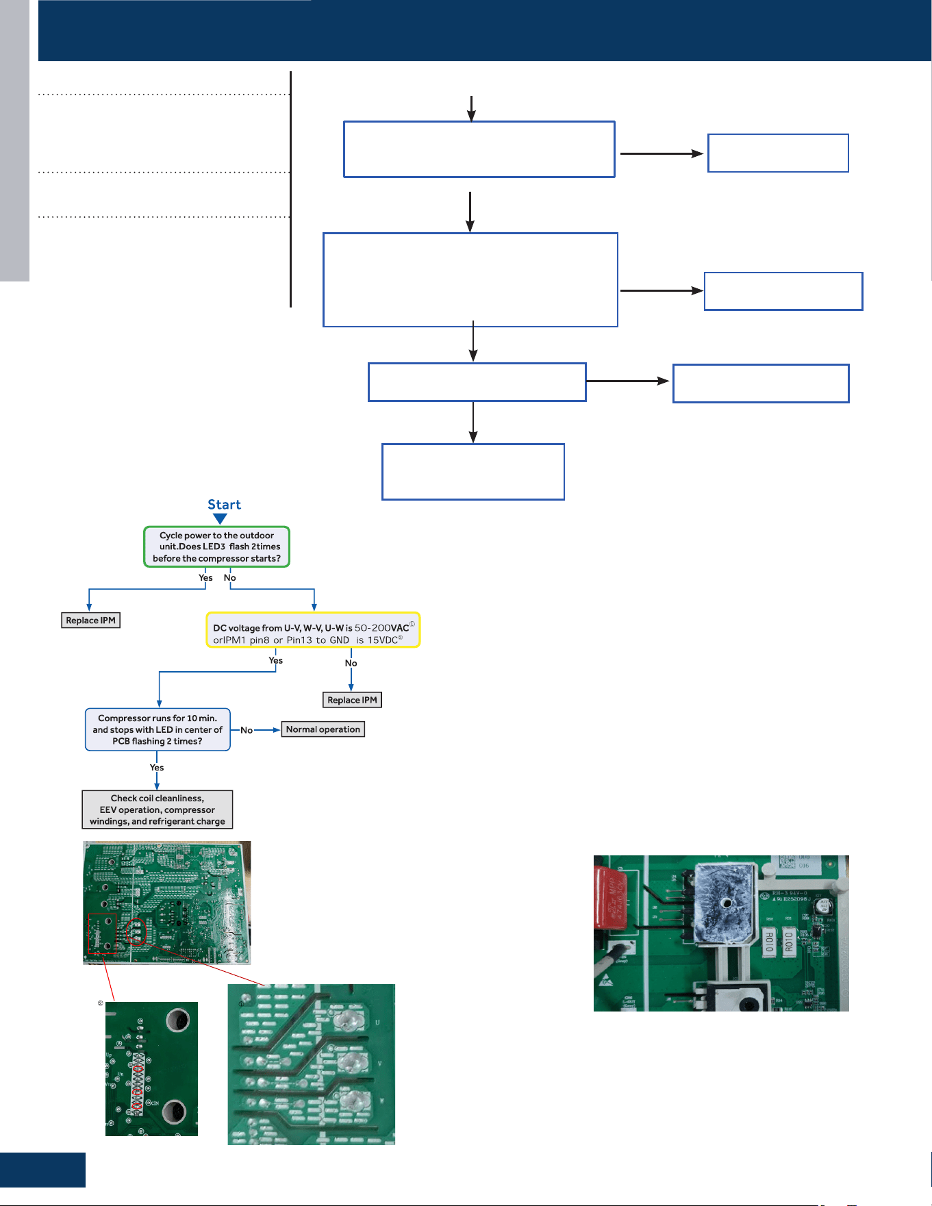
TROUBLESHOOTING & REFERENCES
D6
ENGLISH
PIN8
PIN13
GND
IPM Detect Process Below:
Correct the wiring
Is electric box wiring correct,
and is compressor wiring rmly
connected?
Is compressor normal (compressor coil
resistor, insulation)?
0010744188 2.67±5%Ω
Is power module normal?
Replace compressor
Replace power module
Yes
Yes
Yes
No
No
No
Solve or correct any
failures according to
relative information
Start
ENGLISH
Trigger condition:
The abnormal resistance value of R010
was collected, resulting F1 fault occures.
TROUBLESHOOTING FLOWCHARTS
Error Codes (Indoor/Outdoor)
F1/LED1: 2 Flash
IPM Power Module Failure
(PM power module protection)
Detection Conditions:
Amp limit hot 3 times in 30 minutes
Possible Causes:
• IPM bad
• Loose compressor wire
• Bad compressor
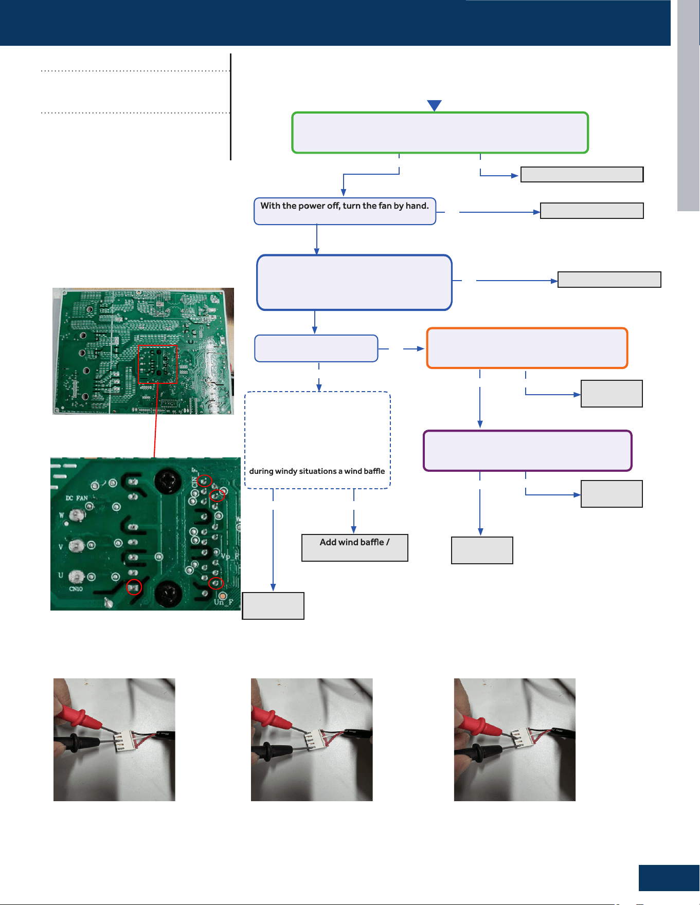
TROUBLESHOOTING & REFERENCES
D7
ENGLISH
No
Ye s
Ye s
Ye s
Ye s
No
Ye s
No
protection from wind.
Fix incoming power supply
Replace the fan motor
Replace the
fan motor.
Replace the
main board.
Start
Check the incoming voltage.
Is it 115VAC (+/- 10%) between L/N?
Does it move / rotate smoothly?
Re-apply power. Does the
fan come on and spin?
No
No
Replace the
main board.
Replace the
main board.
Measure DC voltage at fan motor IPM2 pin1
to GND,Does it measure 160~320VDC (+/-
10%)?
Measure DC voltage at fan motor IPM2
between Pin11 and pin8 ,Does it measure
between 13.5-16.5VDC?
Before going to the next step, is the
unit in an area susceptible to high
winds? High winds blowing into the
fan may cause added resistance
and subsequently lower fan speeds
enough to cause the unit to fault. If
this is the case the unit only faults
may need to be added.
Not Windy Windy
Measure the three wire harnesses of the
motor UVW, and check whether the
resistance values between any two wire
harnesses is 101±8%Ω
Replace the fan motor
No
Ye s
PIN1
GND
PIN8
PIN11
TROUBLESHOOTING FLOWCHARTS
Error Codes (Indoor/Outdoor)
F8/LED1: 9 Flash
Outdoor DC Fan Motor Fault
Detection Conditions:
Resistance values between any two wire
harness connections is 101 +8%Ω
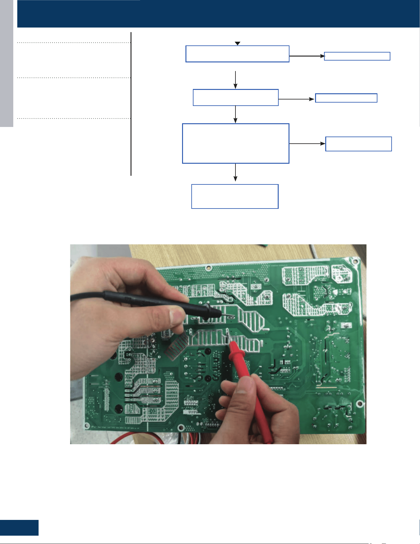
TROUBLESHOOTING & REFERENCES
D8
ENGLISH
Correct power supply
Correct the wiring
Replace power module
Correct power supply
Is power supply voltage
normal?
Is electric box wiring
correct?
Is power module voltage
between terminal P&N more
than 390V or less than 90V
during operation?
Replace power module
Yes
Yes
No
No
Check rectier, rector,
electrolytic capacitor on
inverter main circuit
No
Yes
Start
Replace power module
Correct power supply
TROUBLESHOOTING FLOWCHARTS
Error Codes (Indoor/Outdoor)
F19/LED1: 6 Flash
Power supply is over voltage or
under voltage
Detection Conditions:
• Abnormal voltage detection
• Terminal P&N more than 390V or less
than 90V during operation
• Possible Causes:
Supply voltage not as specied
• Faulty IPM module
• Faulty outdoor PCB
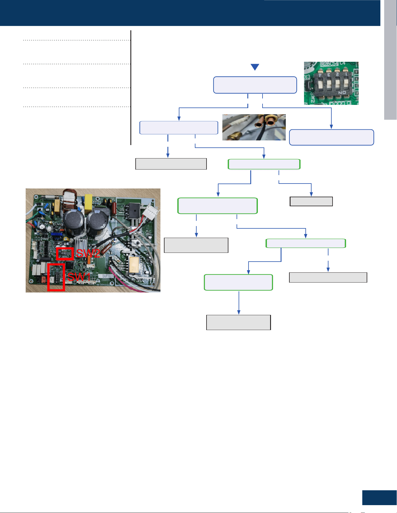
TROUBLESHOOTING & REFERENCES
D9
ENGLISH
Start
Ye s
Ye s
Ye s
Ye s No
No
No
Replace
connecting
pipe
Check for a fan motor
issue
or replace
Replace the EEV
Open louver
PCheck whether the DI I
switch SW-2 is correct?
Indoor louver closed?
The indoor fan rotates slowly
or abnormally
The outdoor EEV damaged
PAdj ust DI I switch
blockage of connecting
pipe
?
Ye sNo
No
The outdoor fan rotates
slowly or abnormally
Check for a fan motor
issue
or replace
TROUBLESHOOTING FLOWCHARTS
Error Codes (Indoor/Outdoor)
F22/LED1: 3 Flash
AC current overload
F23/LED1: 35 Flash
Phase current protection
Detection Conditions:
Current value is over 14.4A
Possible Causes:
• Incorrect compressor wiring
• The power module is bad
• The compressor is bad
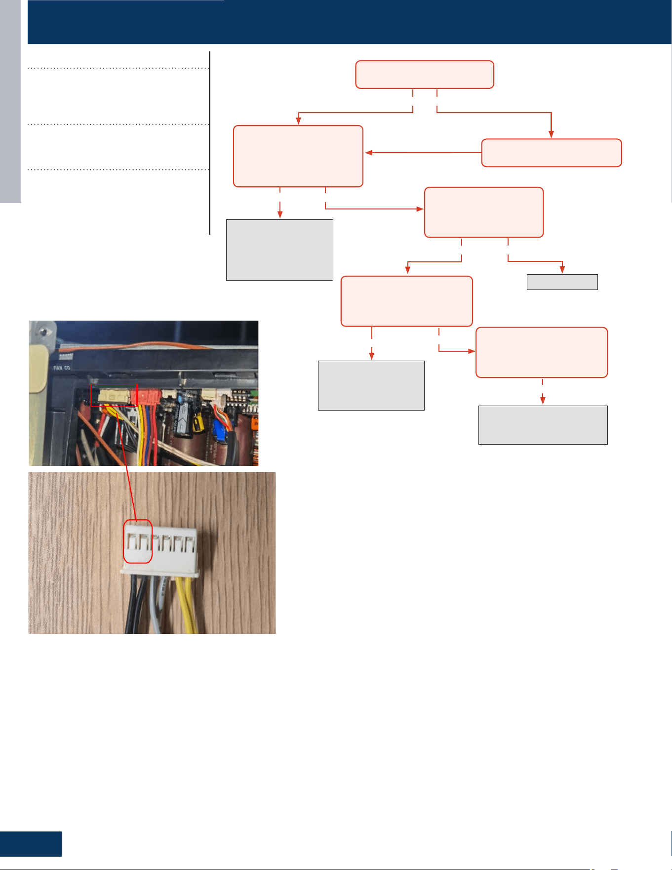
TROUBLESHOOTING & REFERENCES
D10
ENGLISH
Yes
Yes
Yes
Yes No
No
No
Yes
No
Recover refrigerant,
remove moisture and
air from system, charge
with fresh refrigerant to
nameplate amount
Check for a fan motor
issue, restricted line set or
EEV, or lack of refrigerant
Check for a plugged coil or
fılter, a high load, or incorrect
refrigerant charge
Replace sensor
The discharge line temperature is
below 230°F/110°C?
The discharge sensor
ohmreading matches
the resistance table in the
Service Manual?
With system on, the discharge
sensor climbs to 230°F within a
short time, and the compressor
stops?
With system on, the discharge
sensor climbs to 230°F after
several minutes, and the
compressor stops?
Turn power off for 20 min. to
allow the discharge line to cool
Refrigerant static test (system
off for 20 min.) indicates
head pressure converted to
temperature is higher than
ambient?
Mesure this two wire to check resistance
TROUBLESHOOTING FLOWCHARTS
Error Codes (Indoor/Outdoor)
F4/LED1: 8 Flash
Overheat Protection for
Discharge Temperature
Detection Conditions:
Compressor discharge temperature
above 110
O
C
Possible Causes:
• Faulty electronic expansion valve
• Faulty thermistor
• Faulty PCB
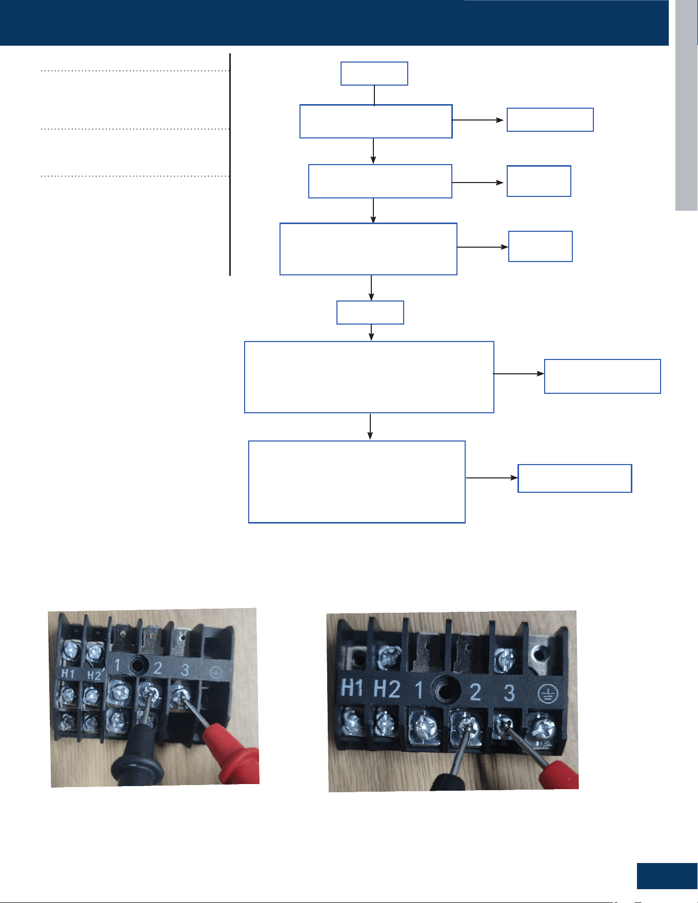
TROUBLESHOOTING & REFERENCES
D11
ENGLISH
Replace wire
Is the communication wire is
shorted?
Is the communication wire
CN23 is disconnected?
Reconnect
Reconnect
Yes
No
No
Yes
Is the wiring connection sequence
correct according to the wiring
diagram?
No
Measure the outdoor terminal block voltage
between communication 3 and 2, and measure the
indoor terminal block between communication 3
and 2 to check. Is the communication wire ok?
Yes
Replace the
communication wire
Power o
Power on
No
Yes
Using a multimeter, measure the terminal
corresponding to the N-line voltage of CN21
from the indoor unit with the communication
failure. Is the voltage normal?
No
PCB is bad, replace PCB
outdoor terminal
indoor terminal
TROUBLESHOOTING FLOWCHARTS
Error Codes (Indoor/Outdoor)
E7/LED1: 15 Flash
ID and OD Loss of
Communication
Detection Conditions:
Outdoor PCB communication failure
• Indoor PCB communication failure
Possible Causes:
• Communication wiring disconnected
• Faulty indoor PCB
• Faulty outdoor PCB
• Faulty Outdoor Fan (may cause com-
munication signal interference)
TROUBLESHOOTING & REFERENCES
D12
ENGLISH
No
No
Yes
Momentary loss of
building power or
acceptable power
quality
Replace compressor
Replace compressor
Replace IPM
Repair or replace
wiring or
connections
When power is off for 5
min. and turned back on,
the compressor runs?
A windings or grounding check
shows issues with compressor?
There is 50-200 VAC across the U, V, and
W solder points on the IPM?
The compressor wires are on the
correct terminals, free of breaks and the
connections at both end are secure?
Yes
Yes
Yes
No
No
No
No
Yes
Yes No
Start
Cycle power to the outdoor unit. Turn system on via
remote control. Does the error occur immediately?
Allow system to run until
error code is displayed
Troubleshoot the pipe
temperature sensor and
temperature monitoring
circuit of the indoor main
board. Replace components
found faulty.
Service the fan or clean
fılters as necessary.
Measure system charge level
and adjust as required.
Yes
Is the pipe at the location of
the pipe temperature sensor
under 149
O
F?
Is fan motor running properly
and fılters unobstructed?
TROUBLESHOOTING FLOWCHARTS
Error Codes (Indoor/Outdoor)
F11/LED1: 18 or 19 Flash
Loss of Compressor
Synchronization
Detection Conditions:
Compressor faulty, miswired or wiring
connection faulty
Possible Causes:
• Faulty wiring
• Faulty compressor
• Faulty PCB
Error Codes (Outdoor)
LED1: 21 Flash
Indoor Unit Over Temperature
(Heating Mode Only)
Detection Conditions:
Activated when the temperature being sensed
by the heat exchanger pipe sensor rises above
149
O
F twice in 30 minutes.
Possible Causes:
• Faulty electronic expansion valve
• Dirty heat exchanger
• Faulty heat-exchange sensor
• Refrigerant undercharge
Note: this is a resetting fault that will
not lockout operation.
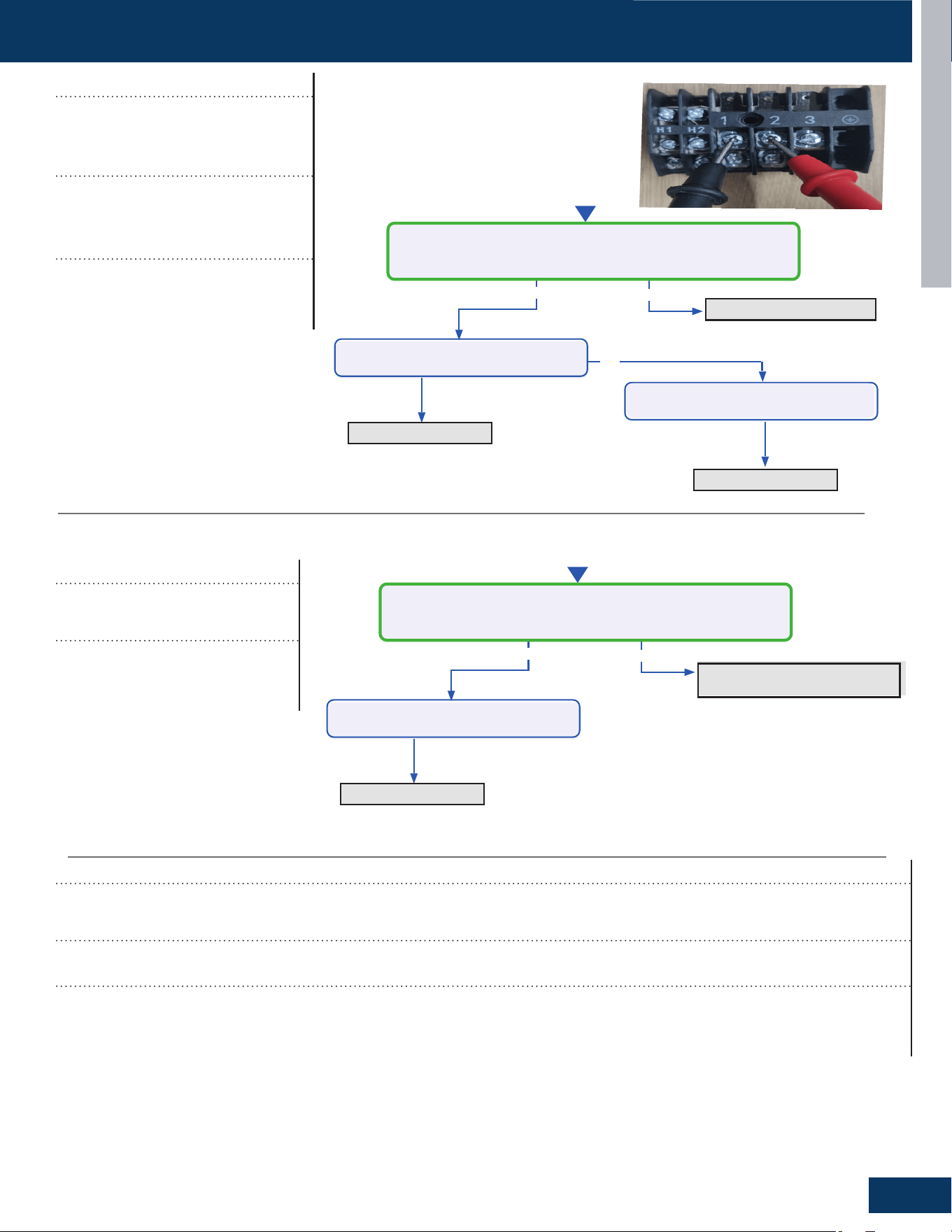
TROUBLESHOOTING & REFERENCES
D13
ENGLISH
No
Ye s
No
Refilling refrigerant
Start
Measure the current between 1/2
Is it 0.6A - 2.5A?
Replace the Coil
Ye s
Replace the PCB
Check the coil leakage
Check the coil leakage
Check the discharge refrigerant
Ye s
No
Start
Measure whether the detection of indoor unit coil temperature
sensor is accurate?
clenupthestuffs
Ye s
Replace the coiltemperature
sensor
Check if there is any stuffs blocking
the air inlet
TROUBLESHOOTING FLOWCHARTS
Error Codes (Indoor/Outdoor)
E22/LED1: 21 Flash
IDU Anti-Frosting Protection
Possible Causes:
• Coil temperature sensor
• IDU air inlet blockage
Error Codes (Indoor/Outdoor)
F27/LED1: 21 Flash
Compressor Current Sampling Circuit Fault
Detection Conditions:
It is compressor block fault, the compressor will not work when this fault happen. It also can be self recovery when this fault happens.
Possible Causes:
• Ambient temperature is too low
• Compressor damage
Error Codes (Indoor/Outdoor)
LED1: 28 Flash
Lack of Refrigerant or
Discharging
Detection Conditions:
Compressor operation frequency
more than 46Hz,the current between
0.6A and 2.5A
Possible Causes:
• Coil leakage
• Discharge refrigerant
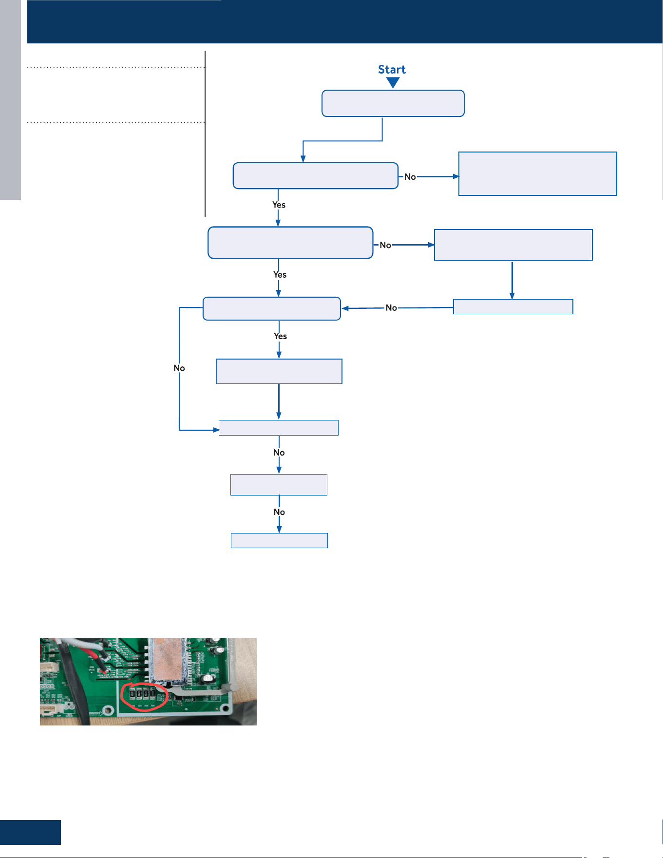
TROUBLESHOOTING & REFERENCES
D14
ENGLISH
Put through thepower and
turn onthe unit
Check whether the compressor
has stopped operation for more than3mins.
The time for stop operation is not enough and
the system's high pressure and low pressure
is unbalanced.
Please wait for 3mins and then
turn on the unit again.
Check whether the compressor wire
(UVW) is connected and the connection
sequenceis correct.
Please improve the connection betweenthe
control board and the compressorand then
connect it well
according tothe wiring diagram.
Check whether the charging
amount of refrigerant is too much.
Does the unit startedup normally?
Charge the refrigerant according to
the Service Manual.
Does the unit startedup normally?
Replace the control board
Eliminate malfunction?
Replace the compressor
Trigger condition
:
• The abnormal resistance value of R020 was collected, resulting in
the F2 error code occurs
TROUBLESHOOTING FLOWCHARTS
Error Codes (Indoor/Outdoor)
F2/LED1: 24 Flash
Module Operated Over Current
(Compressor Startup Failure)
Possible Causes:
• The power supply is abnormal
• Incorrect compressor wiring
• The power module is bad
• The compressor is bad
• System overload
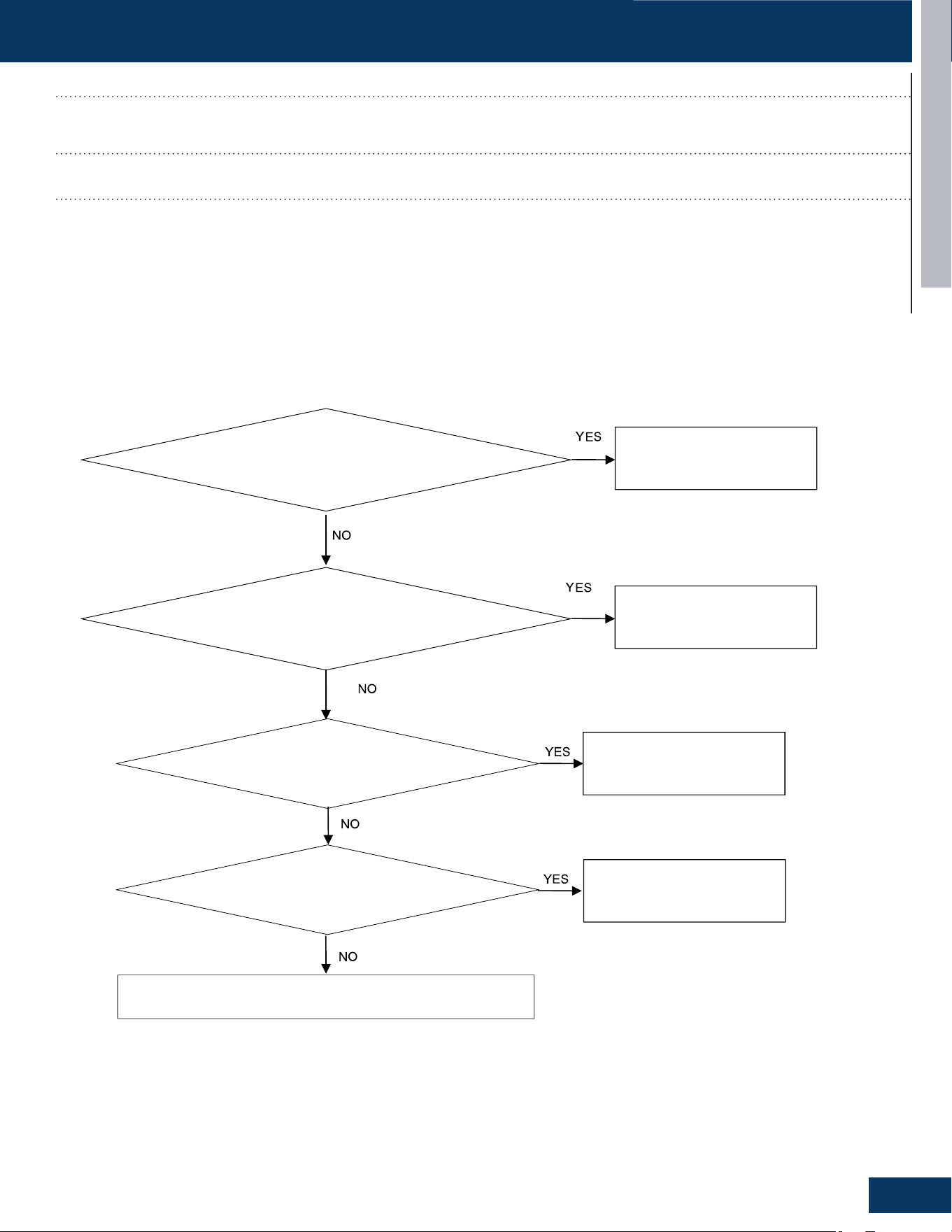
TROUBLESHOOTING & REFERENCES
D15
ENGLISH
Check if the wiring harness is damaged
Replace the wiring harness
Replace the leakage sensor
Check if the wiring harness has poor contact
Reconnect the wiring harness
Check if the PCB is damaged
Replace the PCB
Connect the leakage sensor
Check if the leakage sensor is disconnected with Indoor PCB
TROUBLESHOOTING FLOWCHARTS
Error Codes (Indoor)
bA
DIP Switch Enabled, No Sensor Detected
Detection Conditions:
DIP Switch Enabled, No Sensor Detected
Possible Causes:
• Loose wiring terminals
• Damaged wiring harness
• The leakage sensor is not connected
• PCB damage
* Caution
Be sure to turn o power switch before connect or disconnect connector, or else parts damage may be occurred.

TROUBLESHOOTING & REFERENCES
D16
ENGLISH
Check for refrigerant leakage
Replace the indoor unit or weld
the pipeline
Replace the leakage sensor
TROUBLESHOOTING FLOWCHARTS
Error Codes (Indoor)
AA and Ab
Refrigerant Leakage Fault
Detection Conditions:
• AA: Refrigerant concentration over 10% LFL
• Ab: AA display after 5 minutes and refrigerant concentration of less than 8% LFL detected
Possible Causes:
• Pipe cracking
• The union nut is not secured
* Caution
Be sure to turn o power switch before connect or disconnect connector, or else parts damage may be occurred.

TROUBLESHOOTING & REFERENCES
D17
ENGLISH
Check if the wiring harness is damaged
Replace the wiring harness
Replace the leakage sensor
Check if the wiring harness has poor contact
Reconnect the wiring harness
Check if the PCB is damaged
Replace the PCB
TROUBLESHOOTING FLOWCHARTS
Error Codes (Indoor)
Ac
Leakage Sensor Communication Fault
Detection Conditions:
The communication between the leakage sensor and the PCB is faulty
Possible Causes:
• Loose wiring terminals
• Damaged wiring harness
• PCB damage
* Caution
Be sure to turn o power switch before connect or disconnect connector, or else parts damage may be occurred.
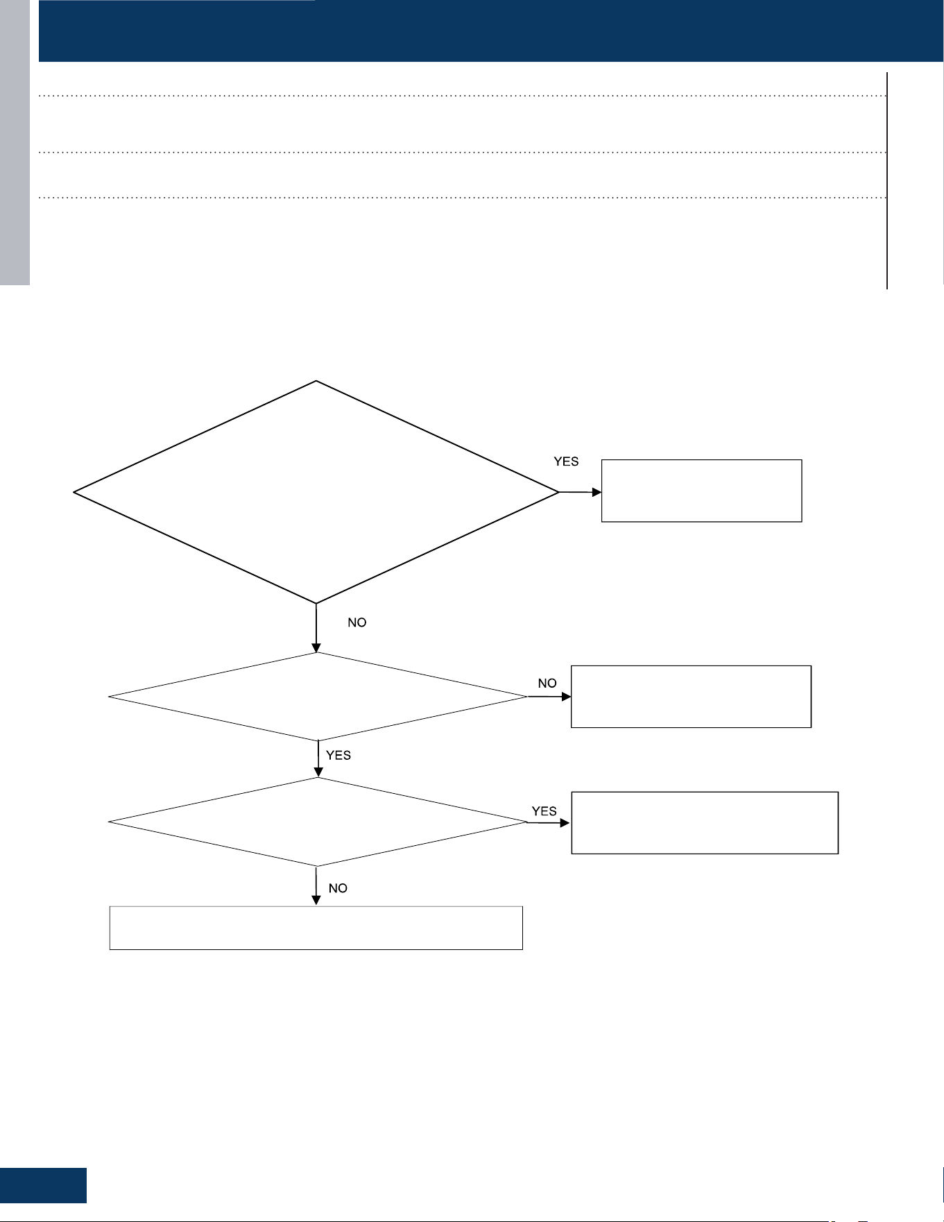
TROUBLESHOOTING & REFERENCES
D18
ENGLISH
Check if the sensor itself is damaged
Replace the leakage sensor
Replace the leakage sensor
Measure whether the sensor voltage is normal
Replace the PCB or leakage sensor
Check the temperature of the usage environment
Normal temperature range -35 to 80 degrees
Celsius
TROUBLESHOOTING FLOWCHARTS
Error Codes (Indoor)
Ad
Leakage Sensor Self-Check Fault
Detection Conditions:
Leakage sensor self-test failed
Possible Causes:
• Power supply overvoltage and undervoltage (5VDC)
• The temperature value detected by the leakage sensor exceeds the limit value
• Internal sensor error
* Caution
Be sure to turn o power switch before connect or disconnect connector, or else parts damage may be occurred.
TROUBLESHOOTING & REFERENCES
D19
ENGLISH
Check the actual usage time of the sensor
Actual usage time reaches 14.5 years
The unit power cycle
Replace the leakage sensor
TROUBLESHOOTING FLOWCHARTS
Error Codes (Indoor)
AE
Leakage Sensor Reaching-End-of-Life Warning
Detection Conditions:
The sensor is 6 months away from the end of its life
Possible Causes:
• The sensor approaching the end of life
• End of life counting error of sensor
* Caution
Be sure to turn o power switch before connect or disconnect connector, or else parts damage may be occurred.

TROUBLESHOOTING & REFERENCES
D20
ENGLISH
Check the actual usage time of the sensor
Actual usage time reaches 15 years
The unit power cycle
Replace the leakage sensor
TROUBLESHOOTING FLOWCHARTS SENSOR RESISTANCE VALUES
Error Codes (Indoor)
AF
Leakage Sensor End- Of- Life
Detection Conditions:
The sensors have reached the end of life
Possible Causes:
• The sensor approaching the end of life
• End of life counting error of sensor
* Caution
Be sure to turn o power switch before connect or disconnect connector, or else parts damage may be occurred.
TROUBLESHOOTING & REFERENCES
D21
ENGLISH
SENSOR RESISTANCE VALUES
Abbr. Denition Type
tAo
Temperatureofoutdoorambient 10K
tc
Temperatureofoutdoorcondenser 10K
td
Temperatureofoutdoordischarge 50K
tE
Temperatureofoutdoordefrost 10K
tS
Temperatureofoutdoorsuction 10K
tdr
Temperatureofcompressordrivermodule 10K
Idr
Currentofthecompressor 10K
Abbr. Denition Type
tAI
Temperatureofindoorambient 10K
TCI
Temperatureofindoorcondenser 10K
Toci
HotGasLeavingthe4-WayValve 10K
Tc 2
EEVLiquidSensor 10K
Tc 1
EEVGasSensor 10K
Tm
ModuleTempSensor 10K
TAI
Temperatureofindoorambient(9K/12KCaliber&
AllCAC)
23K
10K Sensors:
Ambient(allexceptducted,cassette,and9K-12KCaliber)suction,gas,defrost,andpipesensors.
23K Sensors:Ambientsensorsforducted,cassette,and9K-12KCaliber
50K Sensors:Dischargesensors
°F °C
Normal(KΩ)
10K
SENSORS
23K
SENSORS
50K
SENSORS
-22 -30 147.95 513.115 12061.74
-20.2 -29 139.56 478.894 11267.87
-18.4 -28 131.70 447.408 10531.37
-16.6 -27 124.34 418.379 9847.72
-14.8 -26 117.44 391.564 9212.81
-13 -25 110.96 366.751 8622.85
-11.2 -24 104.89 343.754 8074.38
-9.4 -23 99.19 322.407 7564.22
-7.6 -22 93.83 302.567 7089.47
-5.8 -21 88.80 284.105 6647.45
-4 -20 84.07 266.905 6235.71
-2.2 -19 79.62 250.866 5851.99
-0.4 -18 75.44 235.895 5494.21
1.4 -17 71.50 221.911 5160.46
3.2 -16 67.79 208.838 4849.00
5 -15 64.30 196.609 4558.19
6.8 -14 61.01 185.163 4286.55
8.6 -13 57.91 174.443 4032.71
10.4 -12 54.99 164.399 3795.39
12.2 -11 52.23 154.983 3573.43
14 -10 49.62 146.153 3365.73
15.8 -9 47.17 137.87 3171.31
17.6 -8 44.85 130.096 2989.25
19.4 -7 42.65 122.799 2818.67
21.2 -6 40.58 115.946 2658.81
23 -5 38.62
109.51 2508.91
24.8 -4 36.77 103.462 2368.32
26.6 -3 35.01 97.779 2236.39
28.4 -2 33.36 92.437 2112.55
30.2 -1 31.78 87.415 1996.25
32 0 30.30 82.691 1887.00
33.8 1 28.89 78.248 1784.33
35.6 2 27.55 74.067 1687.81
37.4 3 26.29 70.133 1597.04
39.2 4 25.09 66.43 1511.65
41 5 23.95 62.943 1431.28
42.8 6 22.87 59.659 1355.62
44.6 7 21.84 56.566 1284.36
46.4 8 20.87 53.651 1217.23
48.2 9 19.94 50.904 1153.96
50 10 19.06 48.314 1094.32
51.8 11 18.23 45.872 1038.07
53.6 12 17.43 43.569 985.01
55.4 13 16.68 41.395 934.94
57.2 14 15.96 39.343 887.68
59 15 15.28 37.406 843.05
60.8 16 14.63 35.577 800.89
62.6 17 14.01 33.848 761.06
64.4 18 13.42 32.215 723.41
66.2 19 12.86 30.671 687.82
68 20 12.32 29.21 654.16
69.8 21 11.81 27.828 622.32
71.6 22
11.33 26.521 592.18
73.4 23 10.86 25.283 563.66
75.2 24 10.42 24.111 536.65
77 25 10.00 23 511.08
78.8 26 9.60 21.947 486.94
80.6 27 9.21 20.949 464.05
°F °C
Normal(KΩ)
10K
SENSORS
23K
SENSORS
50K
SENSORS
82.4 28 8.85 20.003 442.35
84.2 29 8.50 19.104 421.77
86 30 8.16 18.252 402.24
87.8 31 7.84 17.442 383.72
89.6 32 7.54 16.674 366.13
91.4 33 7.25 15.943 349.43
93.2 34 6.97 15.249 333.58
95 35 6.70 14.588 318.52
96.8 36 6.45 13.96 304.22
98.6 37 6.20 13.362 290.62
100.4 38 5.97 12.794 277.70
102.2 39 5.75 12.252 265.41
104 40 5.53 11.736 253.73
105.8 41 5.33 11.244 242.62
107.6 42 5.13 10.776 232.04
109.4 43 4.94 10.329 221.98
111.2 44 4.76 9.904 212.41
113 45 4.59 9.497 203.29
114.8 46 4.43 9.11 194.61
116.6 47 4.27 8.74 186.34
118.4 48 4.11 8.387 178.46
120.2 49 3.97 8.05 170.95
122 50 3.83 7.728 163.80
123.8 51 3.69 7.421 156.97
125.6 52 3.57 7.127 150.47
127.4 53 3.44
6.846 144.26
129.2 54 3.32 138.35
131 55 3.21 132.70
132.8 56 3.10 127.31
134.6 57 2.99 122.16
136.4 58 2.89 117.25
138.2 59 2.79 112.56
140 60 2.70 108.08
141.8 61 2.61 103.80
143.6 62 2.52 99.70
145.4 63 2.44 95.79
147.2 64 2.36 92.06
149 65 2.28 88.48
150.8 66 2.21 85.06
152.6 67 2.14 81.79
154.4 68 2.07 78.66
156.2 69 2.00 75.67
158 70 1.94 72.80
159.8 71 1.88 70.06
161.6 72 1.82 67.43
163.4 73 1.76 64.91
165.2 74 1.71 62.50
167 75 1.65 60.19
168.8 76 1.60 57.98
170.6 77 1.55 55.86
172.4 78 1.51 53.82
174.2 79 1.46 51.87
176 80 1.41 50.00
177.8 81 1.37 48.21
179.6 82 1.33 46.48
181.4 83 1.29 44.83
183.2 84 1.25 43.25
185 85 1.22 41.72
°F °C
Normal(KΩ)
10K
SENSORS
23K
SENSORS
50K
SENSORS
186.8 86 1.18 40.26
188.6 87 1.14 38.85
190.4 88 1.11 37.50
192.2 89 1.08 36.21
194 90 1.05 34.96
195.8 91 1.02 33.77
197.6 92 0.99 32.62
199.4 93 0.96 31.51
201.2 94 0.93 30.45
203 95 0.91 29.42
204.8 96 0.88 28.44
206.6 97 0.86 27.50
208.4 98 0.83 26.59
210.2 99 0.81 25.71
212 100 0.79 24.87
213.8 101 0.76 24.06
215.6 102 0.74 23.28
217.4 103 0.72 22.52
219.2 104 0.70 21.80
221 105 0.68 21.10
222.8 106 0.67 20.43
224.6 107 0.65 19.78
226.4 108 0.63 19.16
228.2 109 0.61 18.56
230 110 0.60 17.98
231.8 111 0.58 17.42
233.6 112 0.57 16.88
235.4 113 0.55 16.36
237.2 114 0.54 15.85
239 115 0.52 15.37
240.8 116 0.51 14.90
242.6 117 0.50 14.45
244.4 118 0.48 14.01
246.2 119 0.47 13.59
248 120 0.46 13.19
249.8 121 12.80
251.6 122 12.42
253.4 123 12.05
255.2 124 11.70
257 125 11.35
258.8 126 11.02
260.6 127 10.70
262.4 128 10.40
264.2 129 10.10
266 130 9.81
267.8 131 9.53
269.6 132 9.26
271.4 133 9.00
273.2 134 8.74
275 135 8.50
276.8 136 8.26
278.6 137 8.03
280.4 138 7.81
282.2 139 7.60
284 140 7.39
Rev. 10-16-25
©Copyright2025GEAppliances,aHaierCompany.
Ourcontinuedcommitmenttoqualityproductsmay
meanachangeinspecicationswithoutnotice.
Ductless Technical Support
Phone: 866.814.3633
Email: HVACSupport@GEAppliances.com
Online: GEAppliancesAirAndWater.com