Installation, Operation and Maintenance
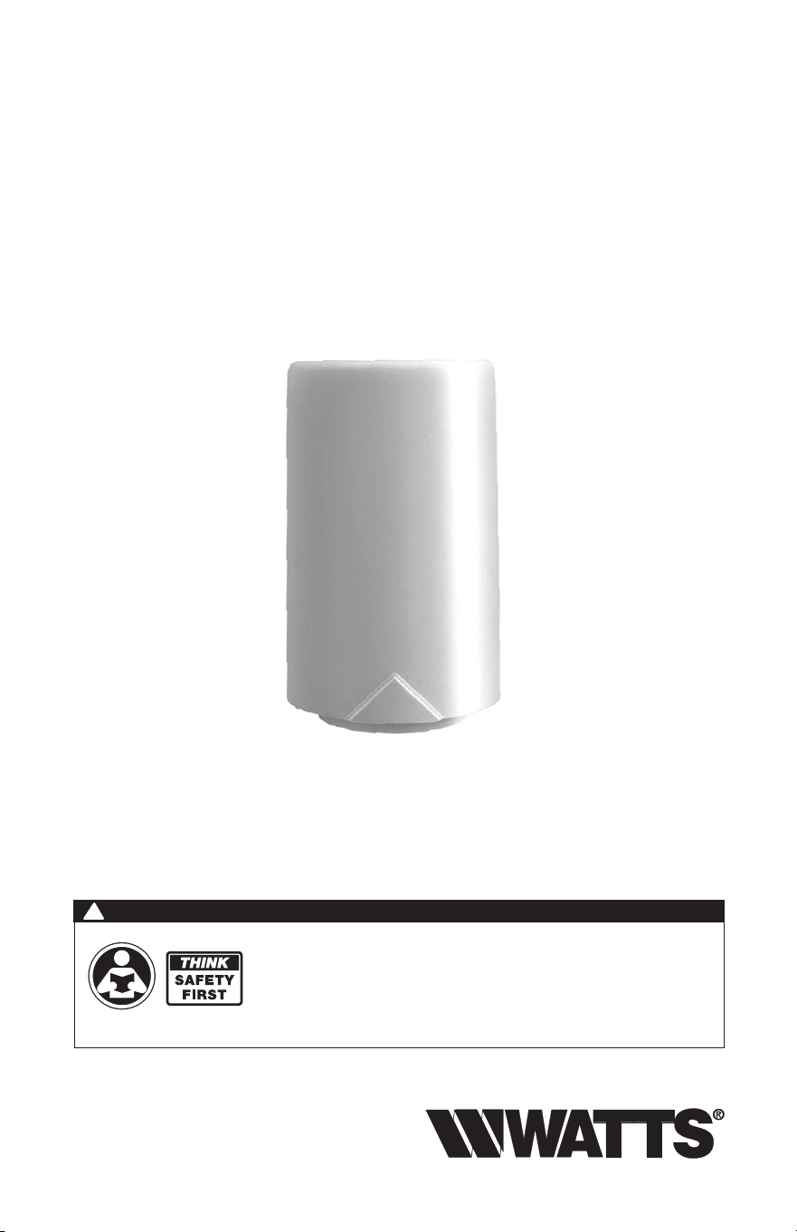
Outdoor Sensor PM-070
The Outdoor Sensor PM-070 provides accurate measurement of the outdoor
air temperature. Many controls and thermostats can connect to the PM-070 to
measure and display the outdoor temperature.
IOM-WR-Outdoor_Sensor-070
Read this Manual BEFORE using this equipment.
Failure to read and follow all safety and use information can result in death,
serious personal injury, property damage, or damage to the equipment.
Keep this Manual for future reference.
WARNING
!

2
Table of Contents
Installation - Outdoor Sensor )&)..................................................3-4
Sensor Testing Instructions ........................................................4
Resistance Table ................................................................5
Technical Data ..................................................................5
3
Installation - Outdoor Sensor PM-070
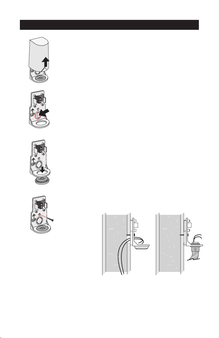
Step One
Mounting The Sensor
NOTE: The temperature sensor (therm-
istor) is built into the PM-070 enclosure.
• The PM-070 can be mounted directly
onto a wall and the wiring should
enter through the back or bottom
of the enclosure. Do not mount the
PM-070 with the conduit knockout
facing upwards as rain could enter the
enclosure and damage the sensor.
• In order to prevent heat transmitted
through the wall from affecting the
sensor reading, it may be necessary
to install an insulating barrier behind
the enclosure.
• The PM-070 should be mounted on
a wall which best represents the heat
load on the building (a northern wall
for most buildings and a southern fac-
ing wall for buildings with large south
facing glass areas). The PM-070
should not be exposed to heat sourc-
es such as ventilation or window
openings.
• The PM-070 should be installed at an
elevation above the ground that will
prevent accidental damage or tam-
pering.
Remove
cover by
sliding
upwards
away from
the base.
To wire from
the back,
remove the
knock-out in
the sensor
base.
If using
conduit,
remove
the flexible
plug from
the base
bottom.
Attach the
base to
the wall,
soffit or
electrical
box.
Sensor with
wiring from back
Sensor with
wiring from
bottom
S1
S1
S1
S1
S1
S1
4
Installation - Outdoor Sensor PM-070
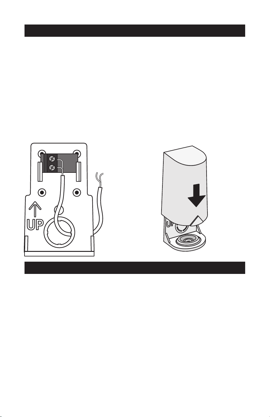
Step Two
Wiring And Testing The Sensor
• Connect 18 AWG or similar wire to the two terminals provided in the enclosure
and run the wires from the PM-070 to the control. Do not run the wires parallel
to telephone or power cables. If the sensor wires are located in an area with
strong sources of electromagnetic interference (EMI), shielded cable or twisted
pair should be used or the wires can be run in a grounded metal conduit. If using
shielded cable, the shield wire should be connected to the Com terminal on the
control and not to earth ground.
• Follow the sensor testing instruction in this brochure and connect the wires to
the control.
• Replace the front cover of the sensor enclosure.
Sensor Testing Instructions
A good quality test meter capable of measuring up to 5,000 kΩ (1 kΩ = 1000Ω) is
required to measure the sensor resistance. In addition to this, the actual tempera-
ture must be measured with either a good quality digital thermometer, or if a ther-
mometer is not available, a second sensor can be placed alongside the one to be
tested and the readings compared.
First measure the temperature using the thermometer and then measure the resis-
tance of the sensor at the control. The wires from the sensor must not be connect-
ed to the control while the test is performed. Using the chart on the following page,
estimate the temperature measured by the sensor. The sensor and thermometer
readings should be close. If the test meter reads a very high resistance, there may
be a broken wire, a poor wiring connection or a defective sensor. If the resistance
is very low, the wiring may be shorted, there may be moisture in the sensor or the
sensor may be defective. To test for a defective sensor, measure the resistance
directly at the sensor location.
Do not apply voltage to a sensor at any time as damage to the sensor may result.
Wires from outdoor
sensor and sensor
common terminals on
Watts control
Sensor is built into
the enclosure
Slide cover
back over
base
S1
S1
5
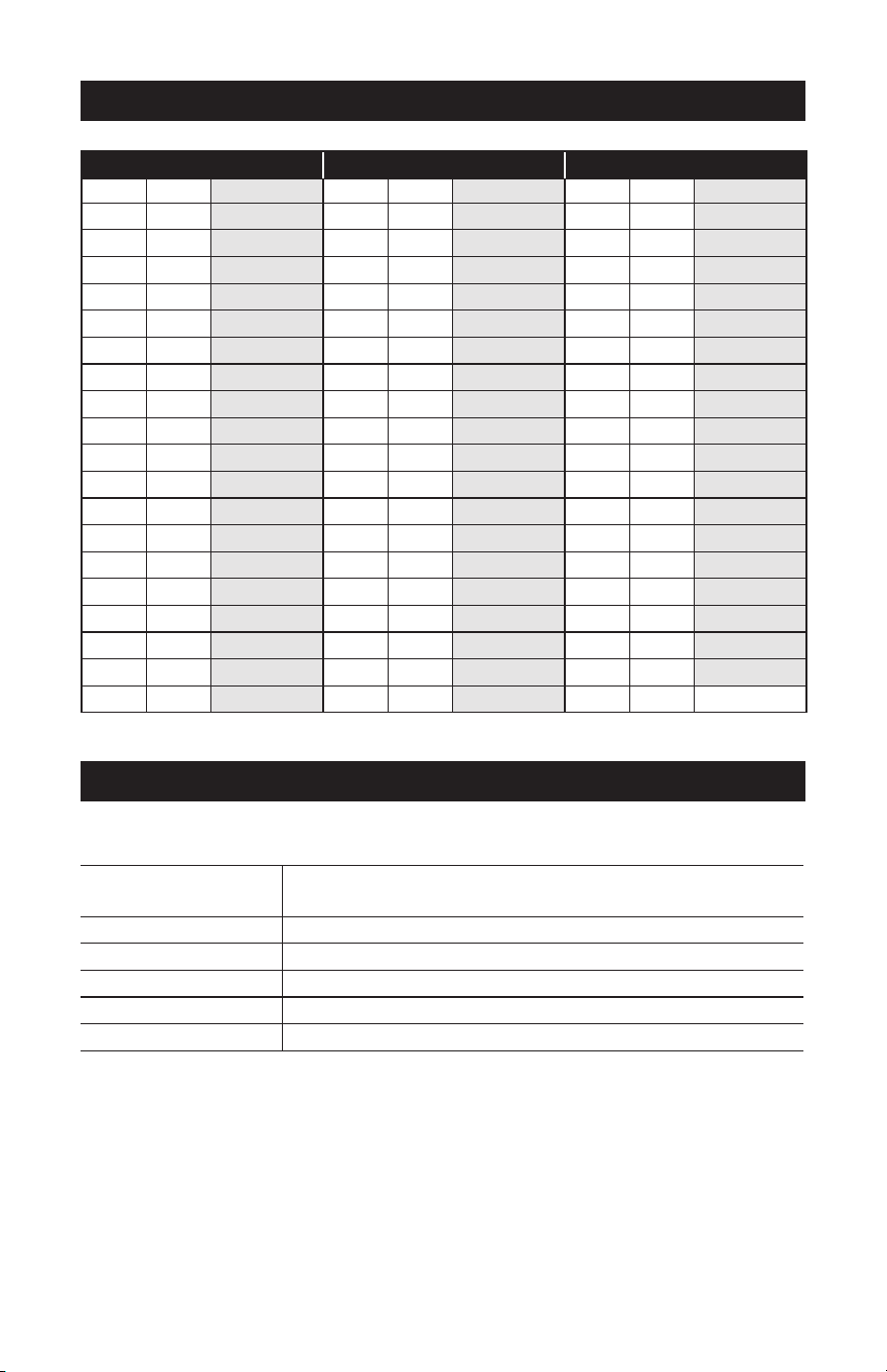
Resistance Table
Technical Data
TEMPERATURE RESISTANCE TEMPERATURE RESISTANCE TEMPERATURE RESISTANCE
°F °C Ω °F °C Ω °F °C Ω
-50 -46 490,813 45 7 22,763 140 60 2,490
-45 -43 405,710 50 10 19,900 145 63 2,255
-40 -40 336,606 55 13 17,436 150 66 2,045
-35 -37 280,279 60 16 15,311 155 68 1,857
-30 -34 234,196 65 18 13,474 160 71 1,689
-25 -32 196,358 70 21 11,883 165 74 1,538
-20 -29 165,180 75 24 10,501 170 77 1,403
-15 -26 139,402 80 27 9,299 175 79 1,281
-10 -23 118,018 85 29 8,250 180 82 1,172
-5 -21 100,221 90 32 7,334 185 85 1,073
0 -18 85,362 95 35 6,532 190 88 983
5 15 72,918 100 38 5,828 195 91 903
10 -12 62,465 105 41 5,210 200 93 829
15 -9 53,658 110 43 4,665 205 96 763
20 -7 46,218 115 46 4,184 210 99 703
25 -4 39,913 120 49 3,760 215 102 648
30 -1 34,558 125 52 3,383 220 104 598
35 2 29,996 130 54 3,050 225 107 553
40 4 26,099 135 57 2,754
Outdoor Sensor PM-070
Literature
ES-WR-Outdoor_Sensor-070,
IOM-WR-Outdoor_Sensor-070
Packaged weight 0.17 lb. (77 g)
Dimensions 2-5/8" H x 1-9/16" W x 1-11/16" D (67 x 40 x 43 mm)
Enclosure White PVC plastic, NEMA type 2
Operating range -60 to 140°F (-51 to 60°C)
Sensor NTC thermistor, 10 kΩ @ 77°F (25°C ±0.2°C) ß=3892

6
Notes

7

IOM-WR-Outdoor_Sensor-070 2216 © 2022 Watts
USA: T: (800) 276-2419 • Watts.com
Canada: T: (888) 208-8927 • Watts.ca
Latin America: T: (52) 55-4122-0138 • Watts.com
Limited Warranty: Watts Regulator Co. (the “Company”) warrants each product to be free from defects in material and workmanship under normal
usage for a period of one year from the date of original shipment. In the event of such defects within the warranty period, the Company will, at its
option, replace or recondition the product without charge.
THE WARRANTY SET FORTH HEREIN IS GIVEN EXPRESSLY AND IS THE ONLY WARRANTY GIVEN BY THE COMPANY WITH RESPECT TO THE
PRODUCT. THE COMPANY MAKES NO OTHER WARRANTIES, EXPRESS OR IMPLIED. THE COMPANY HEREBY SPECIFICALLY DISCLAIMS
ALL OTHER WARRANTIES, EXPRESS OR IMPLIED, INCLUDING BUT NOT LIMITED TO THE IMPLIED WARRANTIES OF MERCHANTABILITY AND
FITNESS FOR A PARTICULAR PURPOSE.
The remedy described in the first paragraph of this warranty shall constitute the sole and exclusive remedy for breach of warranty, and the Company
shall not be responsible for any incidental, special or consequential damages, including without limitation, lost profits or the cost of repairing or
replacing other property which is damaged if this product does not work properly, other costs resulting from labor charges, delays, vandalism,
negligence, fouling caused by foreign material, damage from adverse water conditions, chemical, or any other circumstances over which the
Company has no control. This warranty shall be invalidated by any abuse, misuse, misapplication, improper installation or improper maintenance
or alteration of the product.
Some States do not allow limitations on how long an implied warranty lasts, and some States do not allow the exclusion or limitation of incidental
or consequential damages. Therefore the above limitations may not apply to you. This Limited Warranty gives you specific legal rights, and you
may have other rights that vary from State to State. You should consult applicable state laws to determine your rights. SO FAR AS IS CONSISTENT
WITH APPLICABLE STATE LAW, ANY IMPLIED WARRANTIES THAT MAY NOT BE DISCLAIMED, INCLUDING THE IMPLIED WARRANTIES OF
MERCHANTABILITY AND FITNESS FOR A PARTICULAR PURPOSE, ARE LIMITED IN DURATION TO ONE YEAR FROM THE DATE OF ORIGINAL
SHIPMENT.