Installation & Operation Manual
of8 ©203WattsRadiant
Snow Sensor 095
Introduction
TheSnowSensor095isanaerialmountedsensorthatdetectsfallingsnowand
allowsaWattsRadiantSnowMeltingControl653or654toautomaticallystart
thesnowmeltingequipment.Systemstopisprovidedbythecontrol’stimerorby
manualdisable.TheSnowSensormountstoanominal/2"(6mm)metalorPVC
conduitorpole.Thesensoriswellsuitedtoaddingautomaticstarttoanexisting
snowmeltsystem.
For use with Watts Radiant Snow Melting Controls type: 653 or 654
Snow
Sensor
095
IOM-WR-Snow_Sensor-095324 2of8
ReadthisManualBEFOREusingthisequipment.
Failuretoreadandfollowallsafetyanduseinformationcanresultin
personalinjury,propertydamage,ordamagetotheequipment.
KeepthisManualforfuturereference.
Itisyourresponsibilitytoensurethatthissensorissafelyinstalledaccordingto
allapplicablecodesandstandards.WattsRadiantisnotresponsiblefordamages
resultingfromimproperinstallationand/ormaintenance.
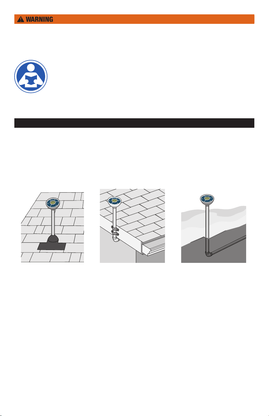
Step 1 - Choosing a Location for the Sensor
Thesensorshouldbeinstalledoutsideonanominal/2"(6mm)PVCorrigid
metalconduitpoleeitheronaroofortothesideofthesnowmeltingsurface.The
sensormustbelocatedawayfromtrees,buildingoverhangsorotherlocationsthat
mayinterferewithfallingsnow.Avoidinstallinginlocationswherethesensormay
bevandalized.Itisbesttopointthefrontfaceofthesensorinthedirectionofany
prevailingwind.
Roof Mounted
Conduitfastenedto
fasciaboard
Ground Mounted
Conduitrununder-
groundwithapole
abovesurface
Roof Mounted
Ensurewater-proof
installationwithflashing
bootorsimilarmethod
3of8 ©203WattsRadiant
Step 2 - Rough In Wiring
Step 3 - Disassembly
Installanominal/2"(6mm)PVCormetalconduitfromtheSnowMeltingControlto
thechosensensorlocation.Pull4conductor8AWGwirefromthesensorlocation
tothecontrollocationthroughtheconduit.Themaximumwirelengthbetweenthe
sensorandthecontrolis500'(50m).
IfusingPVCconduit,donotrunthewiresparalleltotelephoneorpowerlines.Ifthe
sensorwiresarelocatedinanareawithstrongsourcesofelectromagneticnoise,
shieldedcableortwistedpairshouldbeused.Ifusingshieldedcable,oneend
oftheshieldwireshouldbeconnectedtotheComterminalontheSnowMelting
Controlandtheotherendshouldremainfree.Theshieldmustnotbeconnected
toearthground.
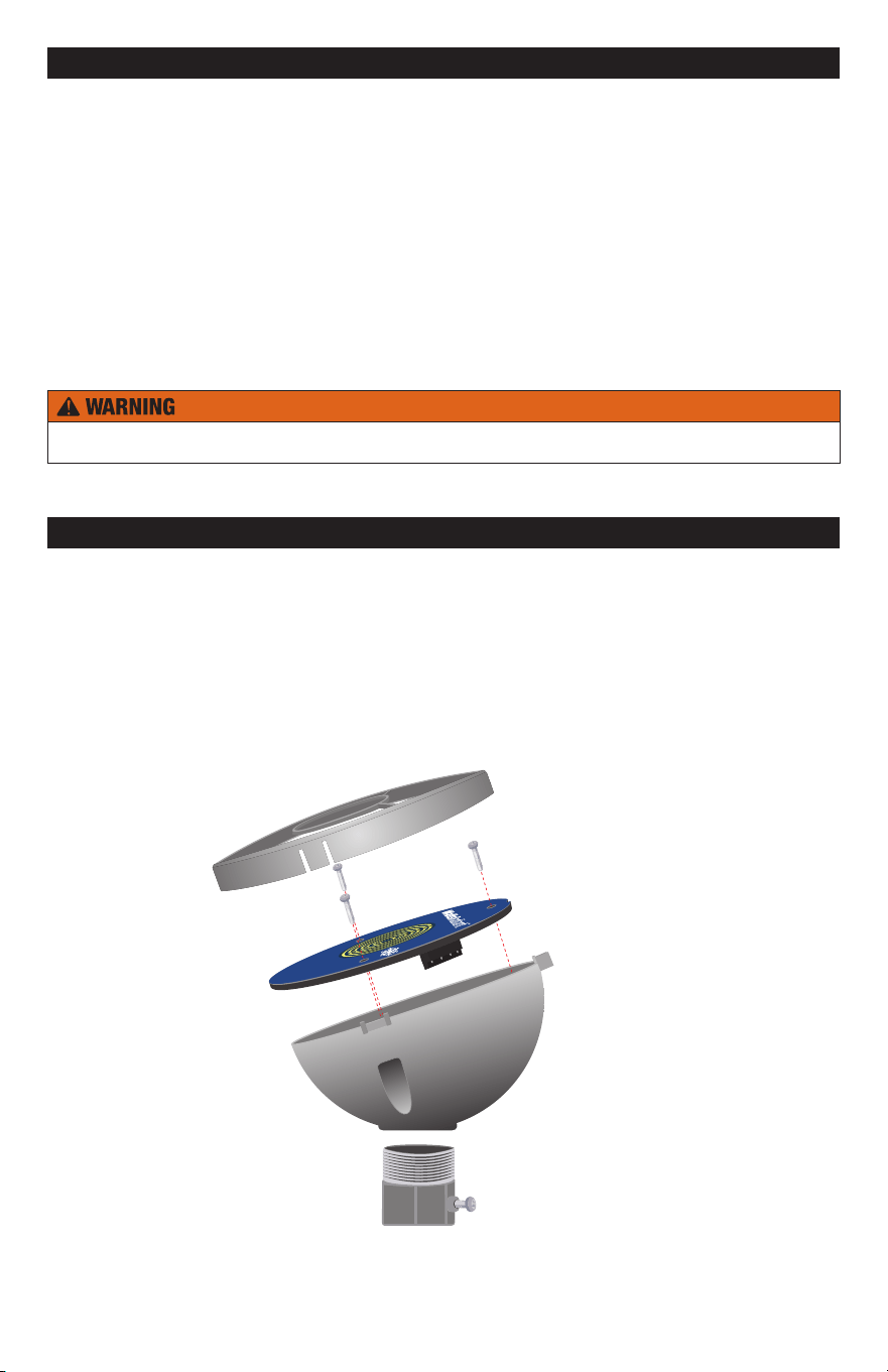
.Removetheouterringbypullinguponthethreecatches.
2.Removethethreescrews.
3.Removethebluesensordiskfromthesensorenclosure.
Avoid scratching any part of the surface of the blue sensor disk. Scratches
will result in corrosion not covered by warranty.
OuterRing
BlueSensorDisk
Sensor
Enclosure
ConduitAdapter
(notincluded)
Metalconduitinroofmountedinstallationsmustbegrounded.
IOM-WR-Snow_Sensor-095324 4of8
Step 5 - Mounting
Step 6 - Wiring
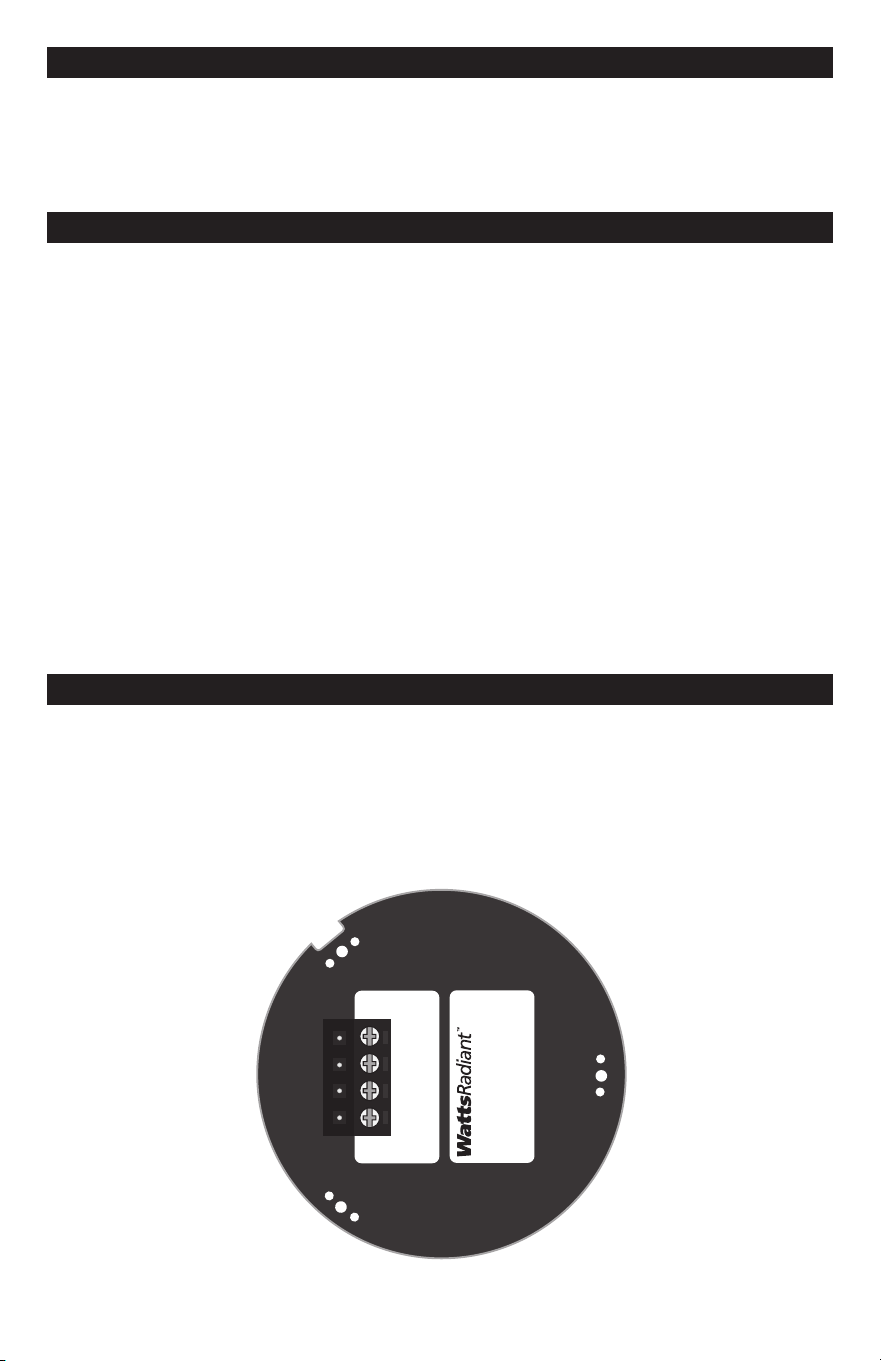
Removethewiringterminalblockbypullingupfromthebluesensordisk.Connect
the4conductorwiretotheyellow(YEL),blue(BLU),red(RED)andblack(BLK)
wiringterminations.Iftheinstalled4conductorcableusesadifferentcolorcode,
thenmakeanoteofthewirecolorversusthewiringterminalcolornames.Push
thewiringterminalplugontothepinsofthebluesensordisk.AttheSnowMelting
Controllocation,connectthecorrespondingwirestotheyellow,blue,redandblack
wireterminations.
TheconduitpolecanbeeitherPVCplasticorrigidmetal.Theconduitpoleshould
bemountedplumbusingalevel.
WhenusingPVCplasticconduitanominal/2"(6mm)PVCmaleterminaladapter
withlocknutisrecommended.
Whenusingrigidmetal,anominal/2"(6mm)rigidmetalconduitadapterwith
setscrewisrecommended.
. Pullthe4conductorwirethroughtheconduit.
2.Installthesensorbodywithconduitadaptertotheconduit.ForPVCconduit
usePVCcementadhesive.Forrigidmetalconduit,tightenthesetscrewuntil
theconduitadapterisfirmlyattachedtotheconduit.
3.Fishthe4conductorwirethroughthesensorbodyandplaceontopofthe
conduitadapter.Pointthesensorbodytowardstheprevailingwinddirection,
ifany.Threadthelocknutontotheconduitadapterandscrewuntiltight.
•
•
YEL
BLU
RED
BLK
Snow Sensor 095
Order# 81016553
Designed &
Assembled in Canada
054-02
May203
Lot23456
Step 4 - Painting the Sensor
Thesensorenclosureismadeofanoff-whiteplasticmaterialthatisUVstable.The
plasticenclosuremaybespraypaintedtomatchthecolorofthebuilding.Do not
paint the blue sensor disk as this will damage the sensor.

5of8 ©203WattsRadiant
Step 7 - Assembly
Maintenance
Testing and Troubleshooting
.
AlignthebluesensordiskWattsRadiantlogowiththehighestpointofthe
sensorenclosurebody.Thebluesensordiskhasanotchthatensures
thesensorisinstalledinthecorrectposition.
2.Insertthethreescrewsintotheholesandscrewthemuntiltight.Donot
overtighten.
3.Alignthethreenotchesoftheouterringwiththesensorbodyandpush
downuntileachofthethreecornershavesnappedontight.
Thesensorisinstalledinaharshenvironment.Accumulationofdirtonthesurfaceof
thesensormayaffectsnowdetection.Thesensorshouldbecheckedonaperiodic
basisand,whennecessary,cleaned.
. Removetheouterringbypullinguponthethreecatches.
2.Aclothwithwarmsoapywatercanbeusedtocleananydirt.
3.Rinsewithwater.
4.Alignthethreenotchesoftheouterringwiththesensorbodyandpush
downuntileachofthethreecornershavesnappedontight.
IftheSnowMeltControlshowsanerrormessagedescribingasensorfailure,perform
thefollowingtestprocedure:
The4conductorwiresatthesensorshouldbedisconnected.
Useagoodqualityelectricaltestingmeterwithanohmscalerangeof0to
2,000,000Ohms.
Usingtheohmmeterandstandardtestingpractices,measuretheresistance
between:
. Theyellow(YEL)andblack(BLK)wiringterminalstomeasurea0kΩsensor
andusetheTemperaturevs.ResistanceTabletocalculatetheapproximate
temperaturereading.Measurethesurfacetemperatureofthe095bluesensor
diskandcompareversustheyellowtoblacktemperaturereading.
2. Measuretheresistancebetweentheblue(BLU)andblack(BLK)wiringterminals.
Whenthesensorsurfaceiscleananddry,thereadingshouldbe2,000,000Ohms.
Whenthesensorsurfaceiswetitshouldbebetween0,000and300,000Ohms.
3.Measuretheresistancebetweenthered(RED)andblack(BLK)wiringterminals
Thisreadingshouldbebetween45to47Ohms.
Ifresistancereadingsareoutsideofthenormaloperatingrange,thesensorhasfailed.
ContactyourwholesalerorWattsRadiantsalesrepresentativeforassistance.
•
•
IOM-WR-Snow_Sensor-095324 6of8
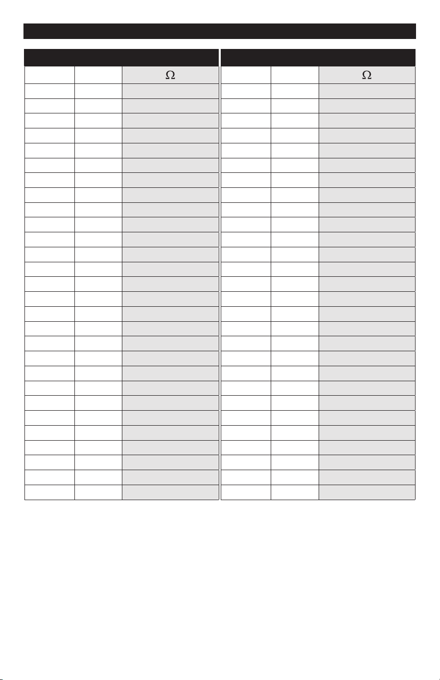
Temperature vs. Resistance Table
Temperature Resistance
°F °C
-50 -46 490,83
-45 -43 405,70
-40 -40 336,606
-35 -37 280,279
-30 -34 234,96
-25 -32 96,358
-20 -29 65,80
-5 -26 39,402
-0 -23 8,08
-5 -2 00,22
0 -8 85,362
5 -5 72,98
0 -2 62,465
5 -9 53,658
20 -7 46,28
25 -4 39,93
30 - 34,558
35 2 29,996
40 4 26,099
45 7 22,763
50 0 9,900
55 3 7,436
60 6 5,3
65 8 3,474
70 2 ,883
75 24 0,50
80 27 9,299
85 29 8,250
Temperature Resistance
°F °C
90 32 7,334
95 35 6,532
00 38 5,828
05 4 5,20
0 43 4,665
5 46 4,84
20 49 3,760
25 52 3,383
30 54 3,050
35 57 2,754
40 60 2,490
45 63 2,255
50 66 2,045
55 68 ,857
60 7 ,689
65 74 ,538
70 77 ,403
75 79 ,28
80 82 ,72
85 85 ,073
90 88 983
95 9 903
200 93 829
205 96 763
20 99 703
25 02 648
220 04 598
225 07 553
7of8 ©203WattsRadiant
WARNING:
This product contains chemicals
known to the State of California to cause cancer
and birth defects or other reproductive harm.
For more information: www.watts.com/prop65
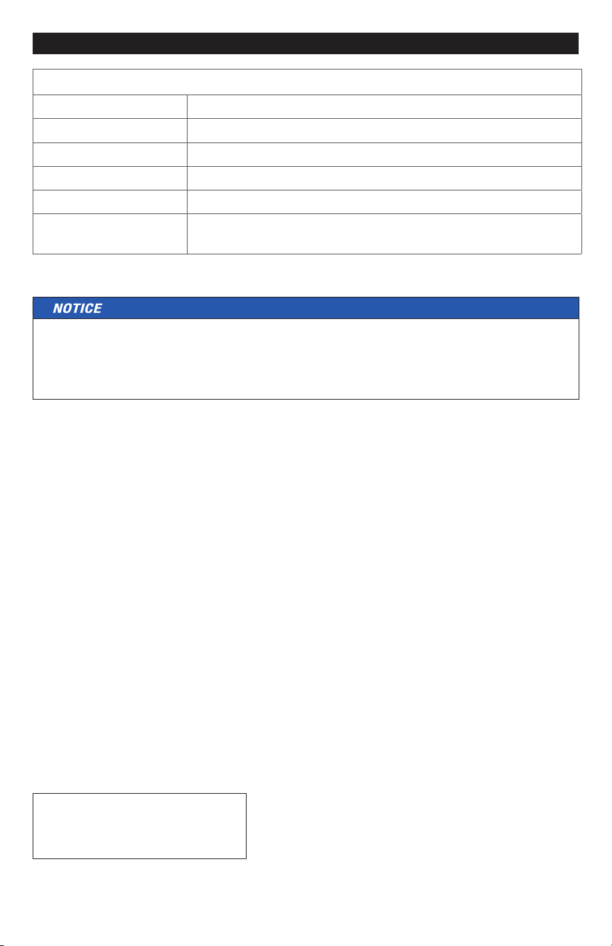
Technical Data
Snow Sensor 095 Air
Literature ES-WR-Snow_Sensor-095,IOM-WR-Snow_Sensor-095
Packagedweight 0.4lbs(80g)
Dimensions -5/6"Hx3-5/32"OD(50mmHx80mmOD)
Enclosure WhitePVCplastic,UVstable,NEMAtype
Operatingrange -40to22°F(-40to50°C)
Compatibleequipment
WattsRadiantElectricSnowMeltingControl653andWatts
RadiantSnowMeltingControl654
TheSnowSensor095mustbeoperatedbyaWattsRadiantSnowMeltingControl
653or654,oracompatibletekmarSnowMeltingControl.Operationofthesensor
byothercontrolsystemsmayresultinelectrolysisfailuresnotcoveredbythe
sensorwarranty.

A Watts Water Technologies Company
USA:Springeld,MO•Tel.(800)276-249•Fax:(47)864-86•www.wattsradiant.com
Canada:Burlington,ONT.•Tel.(905)332-4090•Fax:(905)332-7068•www.watts.ca
IOM-WR-Snow_Sensor-095324 ©203WattsRadiant
Hydronic System Electronic Controls and Thermostats Limited Warranty
WattsRadiant(theCompany)warrantsitshydronicsystemelectroniccontrolsandthermostats(theProduct)tobe
freefromdefectsinmaterialsandworkmanshipundernormalusageforaperiodofoneyearfromthedocumented
dateofinstallationoftheProduct.Intheeventofdefectswithinthewarrantyperiod,theCompanywillreplace
theProductwithoutcharge.Thisremedyisthesoleandexclusiveremedyforbreachofwarranty.Thiswarranty
istransferabletosubsequentowners.
UnderthisLimitedWarranty,theCompanywillprovidethefollowing:
Inordertomakeaclaim,youmust:
(a)ProvidetheCompanywithsufficientdetailsrelatingtothenatureofthedefect,theinstallation,thehistoryof
operation,andanyrepairsthatmayhavebeenmade.
(b)AttheCompany’sdiscretionandattheowner’sexpense,shiptheProducttotheCompanyortheCompany’s
localrepresentativeordistributor.
(c) ProvideproofthattheProductwasinstalledinaccordancewiththeapplicableProductInstallationManualand
anyspecialwrittendesignorinstallationguidelinesbytheCompanyforthisproject.
(d)ProvideproofthattheProductwasinstalledinaccordancewiththeNationalElectricalCode(NEC)orthe
CanadianElectricalCode(CEC),andallapplicablelocalbuildingandelectricalcodes.
(e) Providearetailsalesreceiptorproofofpurchase.
ThefollowingarenotcoveredbythisLimitedWarranty:
(a)Anyincidentalorconsequentialdamage,includinginconvenience,lossoftimeorlossofincome.
(b)
AnylaborormaterialsrequiredtorepairorreplacetheProductthatarenotauthorizedinwritingbytheCompany.
(c) Anylaborormaterialsrequiredtoremove,repairorreplacematerialsotherthantheProducts.
(d)AnyfreightordeliverycostsrelatedtotheProductoranyrelatedelectricalproducts.
WattsRadiantassumesnoresponsibilityunderthisLimitedWarrantyforanydamagetotheProductcausedby
anytradespeople,visitorsonthejobsite,ordamagecausedasaresultofpost-installationwork.ThisLimited
Warrantyshallbeinvalidatedbyanyabuse,misuse,misapplicationorimproperinstallationoftheProducts.The
staffattheCompanyisavailabletoansweranyquestionsregardingtheproperinstallationorapplicationofthe
Productatthistoll-freephonenumber:800-276-249(USA/International)or888-208-8927(Canada).Ifyouare
everindoubtaboutthecorrectinstallationproceduretofollow,oriftheProductappearstobedamaged,youmust
callusbeforeproceedingwiththeinstallationorproposedrepair.
WATTSRADIANTDISCLAIMSANYWARRANTYNOTPROVIDEDHEREIN,INCLUDINGANYIMPLIEDWARRANTY
OFMERCHANTABILITYORIMPLIEDWARRANTYOFFITNESSFORAPARTICULARPURPOSE.WATTS
RADIANTFURTHERDISCLAIMSANYRESPONSIBILITYFORSPECIAL,INDIRECT,SECONDARY,INCIDENTAL,
ORCONSEQUENTIALDAMAGESARISINGFROMOWNERSHIPORUSEOFTHISPRODUCT,INCLUDING
INCONVENIENCEORLOSSOFUSE.THEREARENOWARRANTIESWHICHEXTENDBEYONDTHEFACEOF
THISDOCUMENT.NOAGENTORREPRESENTATIVEOFWATTSRADIANTHASANYAUTHORITYTOEXTEND
ORMODIFYTHISWARRANTYUNLESSSUCHEXTENSIONORMODIFICATIONISMADEINWRITINGBYA
CORPORATEOFFICER.
Somestates/provincesdonotallowtheexclusionorlimitationofincidentalorconsequentialdamagesandsome
states/provincesdonotallowlimitationsonhowlongimpliedwarrantiesmaylast.Therefore,theabovelimitations
orexclusionsmaynotapplytoyou.Thiswarrantygivesyouspecificlegalrightsandyoumayalsohaveother
rights,whichvaryfromstatetostateorprovincetoprovince.SOFARASISCONSISTENTWITHAPPLICABLE
STATE/PROVINCIALLAW,ANYIMPLIEDWARRANTIESTHATMAYNOTBEDISCLAIMED,INCLUDINGIMPLIED
WARRANTIESOFMERCHANTABILITYORFITNESSFORAPARTICULARPURPOSEARELIMITEDINDURATION
TOONEYEARFROMTHEDATEOFMANUFACTURE.
Effective: May,203.ThiswarrantyappliestoallProductspurchasedafterthisdate.