ES
FR
EN
MUSIC SYNTHESIZER
SYNTHÈTISEUR MUSICAL
SINTETIZADOR MUSICAL
Owner’s Manual
Mode d’emploi
Manual de instrucciones
EnglishFrançaisEspañol

MODX+ Owner’s Manual
S1
The model number, serial number, power requirements, etc., may be found on or near the name plate, which is at the bottom of the
unit. You should note this serial number in the space provided below and retain this manual as a permanent record of your purchase
to aid identification in the event of theft.
Model No.
Serial No.
(1003-M06 plate bottom en 01)
Le numéro de modèle, le numéro de série, l'alimentation requise, etc., se trouvent sur ou près de la plaque signalétique du produit,
située dans la partie inférieure de l'unité. Notez le numéro de série dans l'espace fourni ci-dessous et conservez ce manuel en tant
que preuve permanente de votre achat afin de faciliter l'identification du produit en cas de vol.
N° de modèle
N° de série
(1003-M06 plate bottom fr 01)
El número de modelo, el número de serie, los requisitos de alimentación, etc. pueden encontrarse en la placa de identificación o
cerca de ella. Esta placa se encuentra en la parte inferior de la unidad. Debe anotar dicho número en el espacio proporcionado a
continuación y conservar este manual como comprobante permanente de su compra para facilitar la identificación en caso de robo.
Nº de modelo
Nº de serie
(1003-M06 plate bottom es 01)

MODX+ Owner’s Manual
S2
1. IMPORTANT NOTICE: DO NOT MODIFY THIS UNIT!
This product, when installed as indicated in the instructions contained in this manual, meets FCC requirements. Modifications
not expressly approved by Yamaha may void your authority, granted by the FCC, to use the product.
2. IMPORTANT: When connecting this product to accessories and/or another product use only high quality shielded cables.
Cable/s supplied with this product MUST be used. Follow all installation instructions. Failure to follow instructions could void your
FCC authorization to use this product in the USA.
3. NOTE: This product has been tested and found to comply with the requirements listed in FCC Regulations, Part 15 for Class “B”
digital devices. Compliance with these requirements provides a reasonable level of assurance that your use of this product in a
residential environment will not result in harmful interference with other electronic devices. This equipment generates/uses radio
frequencies and, if not installed and used according to the instructions found in the users manual, may cause interference harm-
ful to the operation of other electronic devices. Compliance with FCC regulations does not guarantee that interference will not
occur in all installations. If this product is found to be the source of interference, which can be determined by turning the unit
“OFF” and “ON”, please try to eliminate the problem by using one of the following measures:
- Relocate either this product or the device that is being affected by the interference.
- Utilize power outlets that are on different branch (circuit breaker or fuse) circuits or install AC line filter/s.
- In the case of radio or TV interference, relocate/reorient the antenna. If the antenna lead-in is 300 ohm ribbon lead, change the
lead-in to co-axial type cable.
If these corrective measures do not produce satisfactory results, please contact the local retailer authorized to distribute this type of
product. If you cannot locate the appropriate retailer, please contact Yamaha Corporation of America, 6600 Orangethorpe Ave.,
Buena Park, CA90620, USA.
The above statements apply ONLY to those products distributed by Yamaha Corporation of America or its subsidiaries.
(529-M04 FCC class B YCA 01)
FCC INFORMATION (U.S.A.)
(529-M02 FCC sdoc YCA 01)
COMPLIANCE INFORMATION STATEMENT
(Supplierʼs declaration of conformity procedure)
Responsible Party: Yamaha Corporation of America
Address: 6600 Orangethorpe Ave., Buena Park, Calif. 90620
Telephone: 714-522-9011
Type of Equipment: MUSIC SYNTHESIZER
Model Name: MODX6+, MODX7+, MODX8+
This device complies with Part 15 of the FCC Rules.
Operation is subject to two following conditions:
1) this device may not cause harmful interference, and
2) this device must accept any interference received including interference that may cause undesired operation.
MODX+ Owner’s Manual
S3
For AC adaptor
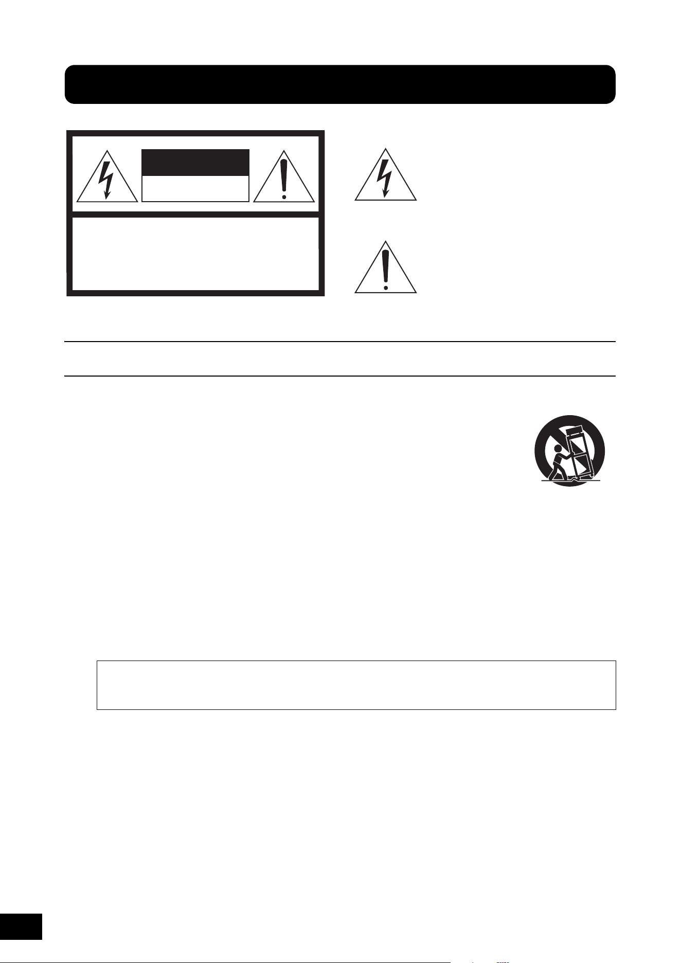
Explanation of Graphical Symbols
The lightning flash with arrowhead symbol
within an equilateral triangle is intended to
alert the user to the presence of uninsulated
“dangerous voltage” within the product’s
enclosure that may be of sufficient
magnitude to constitute a risk of electric
shock to persons.
The exclamation point within an equilateral
triangle is intended to alert the user to the
presence of important operating and
maintenance (servicing) instructions in the
literature accompanying the product.
IMPORTANT SAFETY INSTRUCTIONS
1 Read these instructions.
2 Keep these instructions.
3 Heed all warnings.
4 Follow all instructions.
5 Do not use this apparatus near water.
6 Clean only with dry cloth.
7 Do not block any ventilation openings. Install in
accordance with the manufacturer’s instructions.
8 Do not install near any heat sources such as
radiators, heat registers, stoves, or other apparatus
(including amplifiers) that produce heat.
9 Do not defeat the safety purpose of the polarized or
grounding-type plug. A polarized plug has two
blades with one wider than the other. A grounding
type plug has two blades and a third grounding
prong. The wide blade or the third prong are
provided for your safety. If the provided plug does
not fit into your outlet, consult an electrician for
replacement of the obsolete outlet.
10 Protect the power cord from being walked on or
pinched particularly at plugs, convenience
receptacles, and the point where they exit from the
apparatus.
11 Only use attachments/accessories specified by the
manufacturer.
12 Use only with the cart, stand,
tripod, bracket, or table
specified by the manufacturer,
or sold with the apparatus.
When a cart is used, use
caution when moving the cart/
apparatus combination to
avoid injury from tip-over.
13 Unplug this apparatus during lightning storms or
when unused for long periods of time.
14 Refer all servicing to qualified service personnel.
Servicing is required when the apparatus has been
damaged in any way, such as power-supply cord or
plug is damaged, liquid has been spilled or objects
have fallen into the apparatus, the apparatus has
been exposed to rain or moisture, does not operate
normally, or has been dropped.
(UL60065_03)
CAUTION: TO REDUCE THE RISK OF
ELECTRIC SHOCK, DO NOT REMOVE
COVER (OR BACK). NO USER-SERVICEABLE
PARTS INSIDE. REFER SERVICING TO
QUALIFIED SERVICE PERSONNEL.
CAUTION
RISK OF ELECTRIC SHOCK
DO NOT OPEN
WARNING
TO REDUCE THE RISK OF FIRE OR ELECTRIC SHOCK, DO NOT EXPOSE THIS APPARATUS TO RAIN OR
MOISTURE.
MODX+ Owner’s Manual
S4
Adaptateur secteur
Explication des symboles graphiques
L'éclair avec une flèche à l'intérieur d'un
triangle équilatéral est destiné à attirer
l'attention de l'utilisateur sur la présence
d'une « tension dangereuse » non isolée
à l'intérieur de l'appareil, pouvant être
suffisamment élevée pour constituer
un risque d'électrocution.
Le point d'exclamation à l'intérieur d'un
triangle équilatéral est destiné à attirer
l'attention de l'utilisateur sur la présence
d'instructions importantes sur l'emploi ou la
maintenance (réparation) de l'appareil dans
la documentation fournie.
PRÉCAUTIONS CONCERNANT LA SÉCURITÉ
1 Lisez les instructions ci-après.
2 Conservez ces instructions.
3 Tenez compte des avertissements.
4 Suivez toutes les instructions.
5 N'utilisez pas cet instrument dans un milieu humide.
6 Employez uniquement un chiffon sec pour nettoyer
l'instrument.
7 N'obstruez pas les ouvertures prévues pour la
ventilation. Installez l'instrument conformément aux
instructions du fabricant.
8 N'installez pas l'instrument près d'une source de
chaleur, notamment un radiateur, une bouche de
chaleur, un poêle ou autres (y compris les
amplificateurs).
9 Ne modifiez pas les caractéristiques de la fiche avec
mise à la terre polarisée. Une fiche polarisée est dotée
de deux broches (l'une est plus large que l'autre). Une
fiche avec mise à la terre comprend deux broches,
ainsi qu'une troisième qui relie l'instrument à la terre.
La broche la plus large (ou troisième broche) permet
de sécuriser l'installation électrique. Si vous ne
pouvez pas brancher le cordon d'alimentation dans la
prise d'alimentation, demandez à un électricien de la
remplacer.
10 Protégez le cordon d'alimentation. Cela permet
d'éviter de marcher dessus ou de le tordre au niveau
de la fiche, de la prise d'alimentation et des points de
contact sur l'instrument.
11 N'employez que les dispositifs/accessoires indiqués
par le fabricant.
12 Utilisez uniquement le chariot,
le socle, le trépied, le support
ou le plan indiqués par le
fabricant ou livrés avec
l'instrument. Si vous utilisez un
chariot, soyez prudent si vous
le déplacez avec l'instrument
posé dessus pour éviter de le
renverser.
13 Débranchez l'instrument en cas d'orage ou lorsque
vous ne l'utilisez pas pendant des périodes
prolongées.
14 Confiez toutes les réparations à des techniciens
qualifiés. Des réparations sont nécessaires lorsque
l'instrument est endommagé, notamment dans les cas
suivants : cordon d'alimentation ou fiche défectueuse,
liquides ou objets projetés sur l'appareil, exposition
aux intempéries ou à l'humidité, fonctionnement
anormal ou chute.
(502-M01 UL 60065-1 fr 01)
ATTENTION
RISQUE D'ÉLECTROCUTION
NE PAS OUVRIR
ATTENTION : POUR RÉDUIRE LES RISQUES D'ÉLECTROCUTION,
NE PAS RETIRER LE CAPOT (OU LE DOS). NE CONTIENT
PAS DE PIÈCES NÉCESSITANT L'INTERVENTION
DE L'UTILISATEUR. POUR TOUTE INTERVENTION,
FAIRE APPEL À DES PROFESSIONNELS QUALIFIÉS.
AVERTISSEMENT
N'UTILISEZ PAS L'INSTRUMENT SOUS LA PLUIE OU DANS UN ENVIRONNEMENT HUMIDE, FAUTE DE QUOI VOUS
RISQUEZ DE PROVOQUER UN INCENDIE OU DE VOUS ÉLECTROCUTER.
MODX+ Owner’s Manual
2
PRECAUTIONS
PLEASE READ CAREFULLY BEFORE PROCEEDING
Please keep this manual in a safe and handy place for future reference.
WARNING
• This AC adaptor is designed for use with only Yamaha electronic
instruments. Do not use for any other purpose.
• Indoor use only. Do not use in any wet environments.
CAUTION
• When setting up, make sure that the AC outlet is easily accessible. If
some trouble or malfunction occurs, immediately turn off the power
switch of the instrument and disconnect the AC adaptor from the
outlet. When the AC adaptor is connected to the AC outlet, keep in
mind that electricity is flowing at the minimum level, even if the
power switch is turned off. When you are not using the instrument
for a long time, make sure to unplug the power cord from the wall
AC outlet.
WARNING
Always follow the basic precautions listed below to avoid the possibility of serious injury or even death from electrical
shock, short-circuiting, damages, fire or other hazards. These precautions include, but are not limited to, the following:
• Do not place the power cord near heat sources such as heaters or
radiators. Also, do not excessively bend or otherwise damage the
cord, or place heavy objects on it.
• Only use the voltage specified as correct for the instrument. The
required voltage is printed on the name plate of the instrument.
• Use the specified adaptor (page 71) only. Using the wrong adaptor
can result in damage to the instrument or overheating.
• Check the electric plug periodically and remove any dirt or dust
which may have accumulated on it.
• This instrument contains no user-serviceable parts. Do not open the
instrument or attempt to disassemble or modify the internal
components in any way. If it should appear to be malfunctioning,
discontinue use immediately and have it inspected by qualified
Yamaha service personnel.
• Do not expose the instrument to rain, use it near water or in damp or
wet conditions, or place on it any containers (such as vases, bottles
or glasses) containing liquids which might spill into any openings.
If any liquid such as water seeps into the instrument, turn off the
power immediately and unplug the power cord from the AC outlet.
Then have the instrument inspected by qualified Yamaha service
personnel.
• Never insert or remove an electric plug with wet hands.
• Do not put burning items, such as candles, on the unit. A burning
item may fall over and cause a fire.
• When one of the following problems occur, immediately turn off the
power switch and disconnect the electric plug from the outlet. Then
have the device inspected by Yamaha service personnel.
- The power cord or plug becomes frayed or damaged.
- It emits unusual smells or smoke.
- Some object has been dropped into the instrument.
- There is a sudden loss of sound during use of the instrument.
For AC adaptor
For MODX+
Power supply/AC adaptor
Do not open
Water warning
Fire warning
If you notice any abnormality
DMI-5 1/2
MODX+ Owner’s Manual
3
CAUTION
Always follow the basic precautions listed below to avoid the possibility of physical injury to you or others, or damage
to the instrument or other property. These precautions include, but are not limited to, the following:
• Do not connect the instrument to an electrical outlet using a
multiple-connector. Doing so can result in lower sound quality, or
possibly cause overheating in the outlet.
• When removing the electric plug from the instrument or an outlet,
always hold the plug itself and not the cord. Pulling by the cord can
damage it.
• Remove the electric plug from the outlet when the instrument is not
to be used for extended periods of time, or during electrical storms.
• Do not place the instrument in an unstable position where it might
accidentally fall over.
• Do not place the instrument against a wall (allow at least 3 cm/
one-inch from the wall), since this can cause inadequate air
circulation, and possibly result in the instrument overheating.
• When transporting or moving the instrument, always use two or
more people. Attempting to lift the instrument by yourself may
damage your back, result in other injury, or cause damage to the
instrument itself.
• Before moving the instrument, remove all connected cables, to
prevent damage to the cables or injury to anyone who might trip
over them.
• When setting up the product, make sure that the AC outlet you are
using is easily accessible. If some trouble or malfunction occurs,
immediately turn off the power switch and disconnect the plug from
the outlet. Even when the power switch is turned off, electricity is
still flowing to the product at the minimum level. When you are not
using the product for a long time, make sure to unplug the power
cord from the wall AC outlet.
• Before connecting the instrument to other electronic components,
turn off the power for all components. Before turning the power on
or off for all components, set all volume levels to minimum.
• Be sure to set the volumes of all components at their minimum
levels and gradually raise the volume controls while playing the
instrument to set the desired listening level.
• Do not insert a finger or hand in any gaps on the instrument.
• Never insert or drop paper, metallic, or other objects into the gaps
on the panel or keyboard. This could cause physical injury to you or
others, damage to the instrument or other property, or operational
failure.
• Do not rest your weight on, or place heavy objects on the
instrument, and do not use excessive force on the buttons, switches
or connectors.
• Do not use the instrument/device or headphones for a long period of
time at a high or uncomfortable volume level, since this can cause
permanent hearing loss. If you experience any hearing loss or
ringing in the ears, consult a physician.
Always turn the power off when the instrument is not in use.
Even when the [ ] (Standby/On) switch is in standby status (display is off), electricity is still flowing to the instrument at the minimum level.
When you are not using the instrument for a long time, make sure you unplug the power cord from the wall AC outlet.
Power supply/AC adaptor
Location
Connections
Handling caution
Yamaha cannot be held responsible for damage caused by improper use or modifications to the instrument, or data that is lost or destroyed.
DMI-5 2/2
English

MODX+ Owner’s Manual
4
NOTICE
To avoid the possibility of malfunction/ damage to the product,
damage to data, or damage to other property, follow the notices
below.
Handling
• Do not use the instrument in the vicinity of a TV, radio, stereo
equipment, mobile phone, or other electric devices.
Otherwise, the instrument, TV, or radio may generate noise.
When you use the instrument along with an application on
your iPad, iPhone or iPod touch, we recommend that you set
“Airplane Mode” to “ON” on that device in order to avoid
noise caused by communication.
• Do not expose the instrument to excessive dust or vibrations,
or extreme cold or heat (such as in direct sunlight, near a
heater, or in a car during the day) to prevent the possibility of
panel disfiguration, damage to the internal components or
unstable operation.
• Do not place vinyl, plastic or rubber objects on the
instrument, since this might discolor the panel or keyboard.
• When cleaning the instrument, use a soft and dry/slightly
damp cloth. Do not use paint thinners, solvents, alcohol,
cleaning fluids, or chemical-impregnated wiping cloths.
Saving data
• Edited Performance Data
Edited Performance data is lost when you turn off the power
to the instrument without storing. This also occurs when the
power is turned off by the Auto Power Off function (page 19).
• MIDI and System Settings
MIDI setting data and System setting data are automatically
stored when those corresponding setting displays are
switched to another display. Data is lost when you turn off the
power to the instrument without switching displays. This also
occurs when the power is turned off by the Auto Power Off
function.
• Always save important data to the instrument, or to USB flash
drive (page 60). Keep in mind, however, that data saved to
the instrument may occasionally be lost due to some failure,
an operation mistake, etc. For this reason, you should save
your important data onto USB flash drive (page 60). Before
using a USB flash drive, make sure to refer to page 61.
Information
About copyrights
• Copying of the commercially available musical data including
but not limited to MIDI data and/or audio data is strictly
prohibited except for your personal use.
• This product incorporates and bundles contents in which
Yamaha owns copyrights or with respect to which Yamaha
has license to use others’ copyrights. Due to copyright laws
and other relevant laws, you are NOT allowed to distribute
media in which these contents are saved or recorded and
remain virtually the same or very similar to those in the
product.
* The contents described above include a computer program,
Accompaniment Style data, MIDI data, WAVE data, voice
recording data, a score, score data, etc.
* You are allowed to distribute medium in which your
performance or music production using these contents is
recorded, and the permission of Yamaha Corporation is not
required in such cases.
About functions/data bundled with the
instrument
• This device is capable of using various types/formats of
music data by optimizing them to the proper format music
data for use with the device in advance. As a result, this
device may not play them back precisely as their producers
or composers originally intended.
About this manual
• In this manual, MODX6+, MODX7+, and MODX8+ are
collectively referred to as “MODX+.”
• The illustrations and LCD screens as shown in this manual
are for instructional purposes only, and may appear
somewhat different from those on your instrument.
• Square brackets indicate on-screen buttons, connectors, and
buttons from the control panel.
• Windows is a registered trademark of Microsoft
®
Corporation
in the United States and other countries.
• Apple, macOS, Mac, iPhone, iPad, iPod touch and Logic are
trademarks of Apple Inc., registered in the U.S. and other
countries.
• Ableton is a trademark of Ableton AG.
• IOS is a trademark or registered trademark of Cisco in the
U.S. and other countries and is used under license.
• The company names and product names in this manual are
the trademarks or registered trademarks of their respective
companies.
Yamaha may from time to time update firmware of the
product without notice for improvement in functions and
usability. To take full advantage of this instrument, we
recommend that you upgrade your instrument to the latest
version. The latest firmware can be downloaded from the
website below:
https://download.yamaha.com/
After accessing the Support website (and clicking on
“Firmware/Software”), enter the appropriate model name.

MODX+ Owner’s Manual
5
(58-M02 WEEE en 01)
Information for users on collection and disposal of old equipment:
This symbol on the products, packaging, and/or accompanying documents means that used electrical and electronic
products should not be mixed with general household waste.
For proper treatment, recovery and recycling of old products, please take them to applicable collection points, in accordance
with your national legislation.
By disposing of these products correctly, you will help to save valuable resources and prevent any potential negative effects
on human health and the environment which could otherwise arise from inappropriate waste handling.
For more information about collection and recycling of old products, please contact your local municipality, your waste
disposal service or the point of sale where you purchased the items.
For business users in the European Union:
If you wish to discard electrical and electronic equipment, please contact your dealer or supplier for further information.
Information on Disposal in other Countries outside the European Union:
This symbol is only valid in the European Union. If you wish to discard these items, please contact your local authorities or
dealer and ask for the correct method of disposal.
MODX+ Owner’s Manual
6
Sounds
Design
Z
Z
E
E
R
R
TH
Y
N
T
T
H
H
E
E
S
S
I
I
S
Y
N
N
T
S
Y
Y
N
N
C
S
S
Y
Y
S
Y
S
C
S
S
C
S
M
M
U
U
S
S
I
I
I
C
C
I
NTH
T
H
IC S
YNT
S
YN
SYN
C SY
A message from the MODX+ Development Team
Thank you for purchasing the Yamaha MODX+ Music Synthesizer. We have designed this instrument so that
all of the amazing new ways of the sound expression made possible with the flagship synthesizer MONTAGE
are made even more widely accessible to many players.
Sounds
The MODX+ is equipped with the Motion Control Synthesis engine, the same sound processing
system installed on the MONTAGE. It provides high-definition AWM2 sounds, as well as
dynamic FM-X sounds-and allows them to be controlled seamlessly and flawlessly with various
controllers.
Also, the MODX+ has a new feature for instantly adding rhythm patterns so that the players can
take their music creation forward with dynamic rhythm parts. With this feature, creating rhythmic
changes in the “Motion Controls” is easier than ever!
Design
The MODX+ has been designed to be lightweight and portable, yet full-featured-with the Super
knob, a large-sized color LCD and other controllers that allow the same operability and
appearance as those of the MONTAGE. With the MODX+, you can take the MONTAGE sounds
virtually anywhere for performing.
We really hope that the MODX+ will help your creativity and musical work
grow by leaps and bounds.
Enjoy!
Sincerely,
The Yamaha MODX+ Development Team
MODX+ Owner’s Manual
7
Thank you for purchasing this Yamaha product.
This instrument is a synthesizer designed for use in both live performance and music production.
We recommend that you read this manual carefully so that you can fully take advantage of the advanced and convenient
functions of the instrument.
We also recommend that you keep this manual in a safe and handy place for future reference.
About This Manual
Owner’s Manual (this book)
Provides overall explanations of the basic functions of the instrument. Please use this Owner’s Manual for an overview of the
fundamental operations of the MODX+. If you need more detailed information or instructions on specific functions, use the
Reference Manual described below.
PDF documentation
Reference Manual
Explains in detail about the internal structure and connection examples. Use this manual if you need more detailed
information which is not covered in the Owner’s Manual.
Synthesizer Parameter Manual
This general, cross-product document explains parameters, effect types, effect parameters, and MIDI messages that are
used for all synthesizers. Read the Owner’s Manual and Reference Manual first and then use this parameter manual if
necessary to learn more about parameters and terms that relate to Yamaha synthesizers in general.
Data List
This contains various important lists such as the Performance List, Waveform List, Effect Type List, Arpeggio Type List, and
MIDI Implementation Chart.
Accessories
•AC adaptor
• Owner’s Manual (this book)
• Cubase AI Download Information
How to use the PDF manuals
The Reference Manual, the Synthesizer Parameter Manual, and the Data List are provided as data documents in PDF. The
PDF manuals listed above can be obtained from the Yamaha Downloads web page. To do so, go to the web page using
the following URL, select your country, select “Manual Library,” and then enter “MODX+” into the “Model Name” field, and
then click “Search.”
Yamaha Downloads:
https://download.yamaha.com/
These PDF files can be viewed and read on a computer. When using Adobe
®
Reader
®
to view a PDF file, you can search
for specific words, print a specific page or link to open a desired section in the manual. The term search and link functions
are especially convenient methods of navigating through a PDF file, and we recommend that you use them. The latest
version of Adobe Reader can be downloaded from the following URL.
https://www.adobe.com/products/reader/

MODX+ Owner’s Manual
8
Main Features
High-quality, enhanced sounds covering a
wide range of music styles
The MODX+ has built-in AWM2 and FM-X tone
generators which can be used alone or in combination.
• The AWM2 (Advanced Wave Memory) tone generator
is loaded with a total of 5 GB (in 16-bit linear format) of
preset sounds—the same size as that of MONTAGE.
This means that the MODX+ has a huge variety of
high-quality sounds, including highly realistic Piano
sounds. The MODX+ features 1.75 GB of built-in User
flash memory for storing various sound libraries, and
the stored sounds can be used in the same way as
presets.
• The FM-X tone generator provides a wide expressive
range, giving you both standard FM and new-
generation FM sounds.
Selecting Performances (page 22)
Extensive effect processing
The MODX+ has comprehensive effect systems giving
you a wide array of signal processing options.
• Features independent effects for each part (max. 12
parts plus A/D part), including an Insertion Effect,
three-band EQ before the Insertion effect, and two-
band EQ after it. The Insertion Effect contains a wide
variety of sound processing options, including a VCM
(Virtual Circuit Modeling) effect and a special Vocoder
effect.
• An overall Master Effect including multi-band
compression, and five-band Master EQ.
Editing the Settings (page 37)
Motion Control System for new musical
possibilities
The Motion Control System is a completely new feature
for variably controlling Motions (rhythmical,
multidimensional sound changes) in real time.
The Motion Control System has three main functions:
1) Super Knob:
For creating multi-dimensional sonic changes, and
enhancing those changes with colorful, continually
shifting lighting changes.
2) Motion Sequencer:
For continually variable sound changes.
3) Envelope Follower:
Synchronizes the Motions with tempo and volume of
audio input and other Parts.
The Rhythm Pattern Function
The MODX+ has a powerful Rhythm Pattern function,
with which you can dynamically create sounds using the
Rhythm Parts. It allows you to assign Rhythm Parts
instantly and create rhythmic changes in Motion Control
using the Envelope Follower.
Expanded, enhanced Arpeggio function and
Motion Sequence
The MODX+ enhances your musical expressiveness by
combining the various Arpeggio types—more than
10,000—with the Motion Sequence function that creates
dynamic sound variability over time. You can store all
contents—Arpeggio Type, Motion Sequence, and other
parameters such as Part volume—together as a “Scene,”
and the stored Scenes are assigned to eight buttons,
letting you conveniently and powerfully call up them as
desired while you perform.
Playing the Keyboard (page 26)
Exceptionally convenient live performance
functions
The MODX+ has a Live Set function for easily calling up
Performances as you play on stage. Once you’ve stored
Performances in the desired order, you can concentrate
fully on your playing and never be at a loss on which to
choose. The MODX+ also has SSS (Seamless Sound
Switching) function
*1
for switching between
Performances smoothly without any notes being cut off.
*1: The SSS function is effective for Performances of up to
four Parts.
Creating Your Own Live Sets (page 35)
Enhanced user interface
The enhanced user interface provides greater creative
control and effective operation. Depending on the
intended use, two different interface types are available:
the touch panel for intuitive operations, or the switches
for more secure and quick control. The switches light in
three different ways, letting you instantly understand the
current status of the switches.
Compact design with authentic, expressive
keyboard
The MODX+ is compact in size and weight making it
convenient for easy carrying. Despite its convenient
portability, the MODX+ provides an authentic, natural
keyboard that’s truly a pleasure to perform on: The
MODX6+ has 61 keys and the MODX7+ features a semi-
weighted keyboard of 76 keys, while the MODX8+ has
88 keys with a high-quality GHS keyboard.
Comprehensive system connectivity
The MODX+ features a built-in 4-channel in/10-channel
out USB audio interface for recording the high-quality
sound of the MODX+ (at 44.1 kHz sampling frequency)
on a Mac or Windows PC—without the need for a
separate device! The connections are also compatible
with iOS devices.
MODX+ Owner’s Manual
9
PRECAUTIONS ...........................................................................2
A message from the MODX+ Development Team......................6
About This Manual ......................................................................7
Accessories................................................................................. 7
Main Features.............................................................................. 8
Controls and Functions 10
Top Panel ................................................................................. 10
Rear Panel ................................................................................16
Setting Up 18
Power Supply ............................................................................18
Connecting Speakers or Headphones......................................18
Powering Up the System........................................................... 18
Auto Power Off function ............................................................19
Restoring the initial factory settings (Initialize All Data) ............ 19
Basic Operation and Displays 20
Selecting Performances 22
Selecting a Performance from the Live Set...............................23
Switching Performances ...........................................................23
Using the Category Search function .........................................24
Playback Audition phrase .........................................................25
Playing the Keyboard 26
Performance Play display..........................................................26
Switching a Part on/off ..............................................................27
Using the Arpeggio function .....................................................28
Using the Motion Sequencer function.......................................28
Using controllers to change the sound .....................................29
Using the Knobs to change the sound .....................................30
Using the Super Knob to change the sound............................. 31
Mixing........................................................................................33
Using the Scene function ..........................................................34
Creating Your Own Live Sets 35
Registering a Performance to a Live Set................................... 35
Sorting registered Performances in a Live Set.......................... 35
Editing the Settings 37
Performance Editing..................................................................37
Part Editing................................................................................38
Part Effect Editing......................................................................39
How Parts are assigned to a Performance................................ 40
Creating a Performance by combining Parts............................ 41
Recording and Playback 45
Terminology............................................................................... 45
MIDI (Song) Recording ............................................................. 45
Playing a Song .......................................................................... 47
Recording your performance as audio ..................................... 48
Playing an audio file .................................................................. 48
Using as a Master Keyboard 49
Making settings for use as a master keyboard—Zone ............. 49
Connecting a Microphone or Audio Equipment 50
Playing the keyboard along with the sound input from the
A/D INPUT [L/MONO]/[R] jacks ................................................ 50
Making Global System Settings 51
Setting automatic power-on tasks............................................. 51
Setting button lamp behavior .................................................... 51
Turning various functions on/off................................................ 51
Changing the Master Tuning..................................................... 52
Changing the Velocity Curve .................................................... 52
Changing the font size of the Live Set ...................................... 53
Connecting External MIDI Instruments 54
Connecting to an external MIDI device with the MIDI [IN], [OUT]
terminals.................................................................................... 54
Connecting to an external MIDI device with the [USB TO DEVICE]
terminal...................................................................................... 54
Using a Connected Computer 55
Connecting to a computer ........................................................ 55
Creating a Song with a computer ............................................. 57
Saving/Loading Data 60
Saving the settings to a USB flash drive ................................... 60
Loading the settings from a USB flash drive............................. 60
Precautions when using the [USB TO DEVICE] terminal .......... 61
Using USB flash drives ............................................................. 61
Shift Function List 62
Display Messages 63
Troubleshooting 66
Specifications 71
Index 73
Contents
MODX+ Owner’s Manual
10
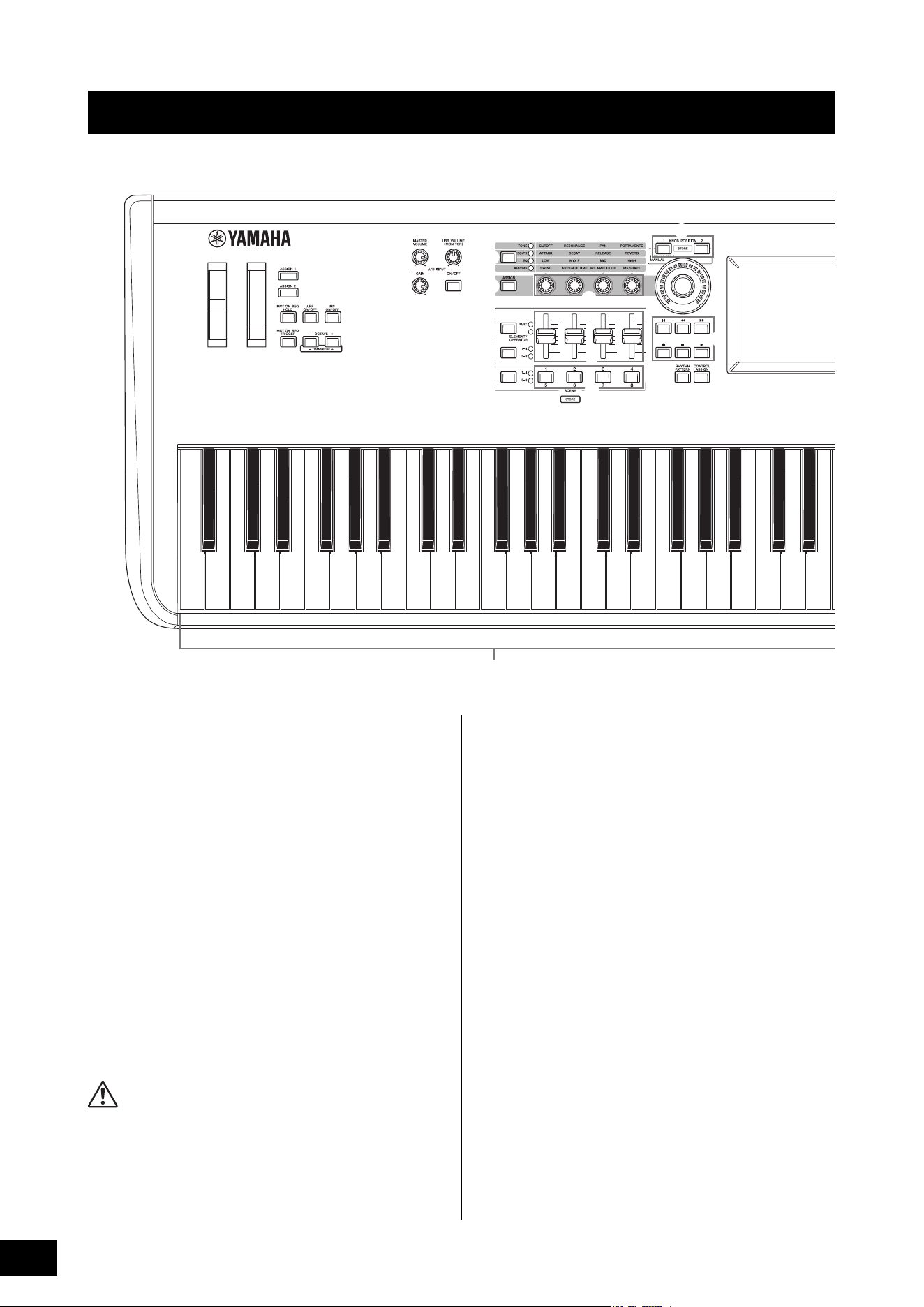
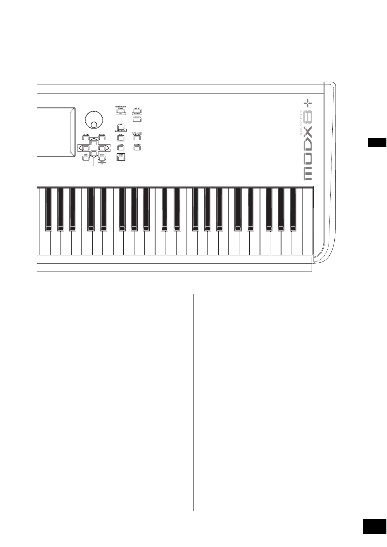
Top Panel
1 Keyboard
The MODX6+ features a 61-key keyboard, while the
MODX7+ has 76 keys and the MODX8+ has 88 keys. With
initial touch, the instrument senses how strongly or softly you
play the keys, and uses that playing strength to alter the
sound in various ways, depending on the selected
Performance.
2 Pitch Bend wheel
Controls the pitch bend effect. You can also assign other
functions to this controller.
3 Modulation wheel
Controls the modulation effect. You can also assign other
functions to this controller.
4 [MASTER VOLUME] knob
Turn the knob clockwise or counterclockwise to control the
output level from the OUTPUT [L/MONO]/[R] jacks and the
[PHONES] jack.
CAUTION
Do not listen with the headphones at high volume for long periods of
time. Doing so may cause hearing loss.
5 [USB VOLUME (MONITOR)] knob
Controls the volume of the audio input from the [USB TO
HOST] jack to OUTPUT [L/MONO] and [R] jacks, and
[PHONES] jack.
6 A/D INPUT [GAIN] knob (page 50)
Use this to adjust the input gain of the audio signals at the
A/D INPUT [L/MONO]/[R] jacks. Turning the knob clockwise
increases the gain level.
NOTE
You may need to change the setting depending on the input level of
the external equipment connected to the A/D INPUT [L/MONO]/[R]
jacks, in the following order: [UTILITY] [Settings] [Audio I/O]
[A/D Input]. When the output level of the connected equipment (such
as a microphone, guitar or bass) is low, set this parameter to “Mic.”
When the output level of the connected equipment (such as a
synthesizer keyboard or CD player) is high, set this parameter to
“Line.”
7 A/D INPUT [ON/OFF] button (page 50)
Switches whether or not this instrument accepts the audio
signal input via the A/D INPUT [L/MONO]/[R] jacks. When A/
D Input is enabled, the button lights; when disabled, it turns
off.
Controls and Functions
C1E0 F0 G0 A0 B0C0 D0A-1 B-1 C2
C3
1
23
4
7
6
H
G
C
B
%
8
9
)
D
^
!
(
#
$
A
I
F
@
*
&
5
E
MODX+ Owner’s Manual
11
Controls and Functions
8 [ASSIGN 1] and 9 [ASSIGN 2] buttons
(Assignable switches 1 and 2)
You can call up the specific Element/Operator of the
selected Performance by pressing each of these buttons
during your keyboard performance. In addition, you can
assign other functions to these switches. When one of these
effects is turned on, the corresponding button will light up
and vice-versa.
) [MOTION SEQ HOLD] (Motion Sequencer
hold) button
Pressing this button while the Motion Sequencer is playing,
results in the sound being held or frozen at the exact point in
the sequence when the button was pressed. When the hold
effect is turned on, the button lights.
! [MOTION SEQ TRIGGER] (Motion Sequencer
trigger) button
When the Trigger Receive parameter of the Motion
Sequencer is set to ON, pressing this button starts Motion
Sequence playback. The button lights fully when pressed.
@ [ARP ON/OFF] (Arpeggio on/off) button
Press this button to enable or disable playback of the
Arpeggio. If the Arpeggio Switch of the selected Part is set to
off, however, pressing this button has no effect. When
Arpeggio is enabled, the button lights; when disabled, it
turns off.
# [MS ON/OFF] (Motion Sequencer on/off)
button
Determines whether the Motion Sequencer is active or not. If
the Motion Sequencer switch of the selected Part or Lane is
set to off, however, pressing this button has no effect. When
the Motion Sequencer is active, the button lights.
$ OCTAVE [-] and [+] buttons
Use these buttons to change the octave range of the
keyboard. These buttons also function as Transpose [-] and
[+] buttons. To lower or raise the pitch of the note in semitone
steps, hold down the [SHIFT] button and press the
corresponding [-]/[+] button. To restore the normal octave
setting, press both buttons simultaneously. The buttons light
or flash in different ways depending on the octave setting.
For details, see the Reference Manual PDF document.
C4 C5 C6 C7
J
K
P
L
M
N
O
c
Q
R
S
T
a
d
b
The illustration shows the MODX8+, but the information applies to all models.
MODX+ Owner’s Manual
12
Controls and Functions
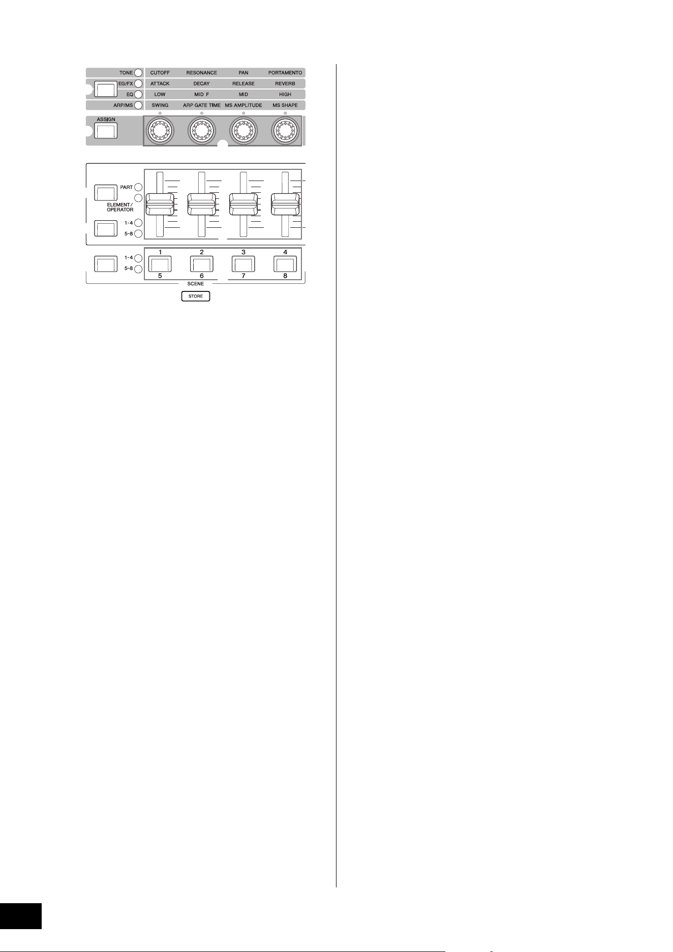
% Knob Function [TONE]/[EG/FX]/[EQ]/[ARP/
MS] button
Use this button to select functions to be assigned to Knobs.
The lamp next to the currently active parameters will light.
While the instrument is in the Performance Control status
(page 30), the function is applied commonly to all Parts,
while in the Part Control status (page 30), the function is
applied to the selected Part. The lamp for the selected
function will light.
^ [ASSIGN] button
Switches Knobs to function as Assign 1–4 or as Assign 5–8.
While the instrument is in the Performance Control status
(page 30), the function is applied commonly to all Parts,
while in the Part Control status (page 30), the function is
applied to the selected Part. The button lights when Assign
1–4 is selected, and the button flashes when Assign 5–8 is
selected.
& Knobs 1–4 (5–8)
These four highly versatile knobs on the panel let you adjust
various important parameters, such as the current Part,
Arpeggio tempo, and the Motion Sequencer.
Pressing the Knob Function [TONE]/[EG/FX]/[EQ]/[ARP/MS]
button on the upper left, or the [ASSIGN] button on the left
changes the functions assigned to these knobs. These
knobs function as Assignable Knobs when the [ASSIGN]
button is lit or flashing.
* Slider Function [PART]/[ELEMENT/
OPERATOR] button
Sets four Control Sliders on the panel to use for controlling
Parts or for controlling Elements. Each time you press this
button, the slider function alternates between PART and
ELEMENT/OPERATOR. The lamp for the selected function
lights up.
( Slider Select [1–4] [5–8] button
Selects four Control Sliders on the panel to use as 1–4 or 5–
8. Each time you press this button, the setting alternates
between 1–4 and 5–8. When the setting is 1–4 or 5–8, the
lamp for the selected setting lights up.
When you press the Slider Select button while holding down
the [SHIFT] button, you can set the Control Sliders to
function as 9–12 or 13–16. When the setting is 9–12 or 13–
16, the lamp for the selected setting flashes.
A Control Sliders 1–4 (5–8 / 9–12 / 13–16)
These sliders control the volume balance of the sound, by
letting you adjust the individual levels of the 16 Parts (1–4 /5–
8 / 9–12 / 13–16), the eight Elements for Normal Parts
(AWM2), the eight FM Operators for a Normal Part (FM-X),
and eight Keys of the Drum Part, in different ways depending
on the conditions of the various buttons.
NOTE
• If all of the Control Sliders are set to the minimum, you may not
hear any sound from the instrument, even when playing the
keyboard or a Song. If this is the case, raise all the sliders to a
suitable level.
• The [MASTER VOLUME] knob controls the overall audio output
level of this instrument. On the other hand, the Control Sliders
control the level of each Element/Key/Operator of the Parts and the
volume for each Part of the Performance as a parameter.
Accordingly, the values set via the Control Sliders can be stored as
Performance data.
B Scene Select [1–4] [5–8] button
Selects four SCENE buttons on the panel to use as Scenes
1–4 or Scenes 5–8. Each time you press this button, the
setting alternates between 1–4 and 5–8. The lamp for the
selected function lights up.
C SCENE [1/5] [2/6] [3/7] [4/8] buttons
You can assign different “snapshots” of important Part-
related parameters such as track mute status and the basic
Mixing setup to each of the SCENE buttons. You can switch
these buttons to function as Scenes 1–4 or as Scenes 5–8 by
pressing the Scene Select button.
When Scene-related parameters are edited and any of the
SCENE [1/5]–[4/8] buttons is pressed while holding down
the [SHIFT] button, the edit is stored for the currently
selected [SCENE] button. The stored information is restored
by pressing the selected button. The currently selected
button fully lights, the button stored information lights dimly,
and the button without stored information is turned off.
C
B
%
^
(
A
*
&
MODX+ Owner’s Manual
13
Controls and Functions
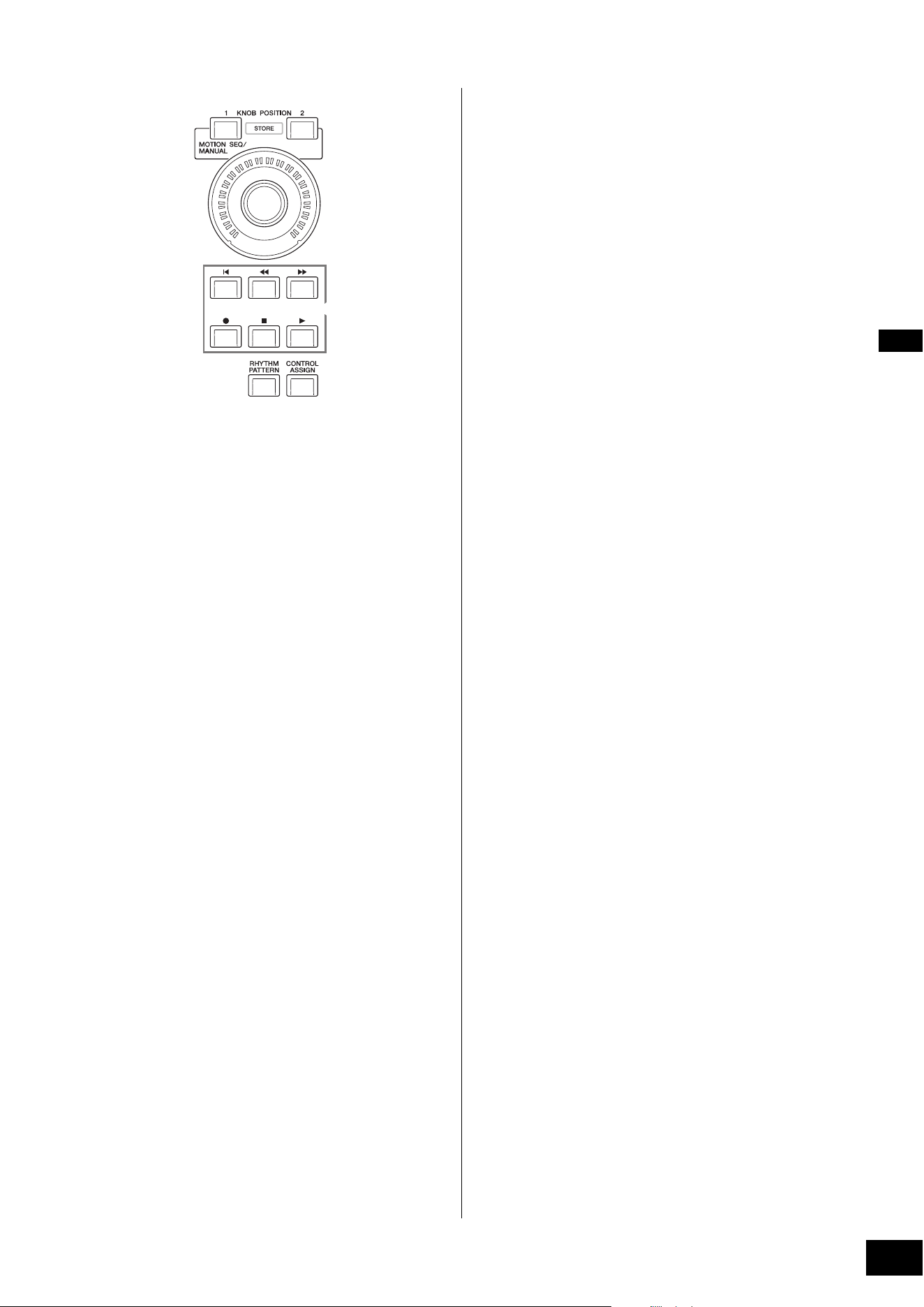
D KNOB POSITION [1] and [2] buttons
Stores the parameter values of Assign 1–8. You can instantly
switch between the two buttons.
Pressing the KNOB POSITION [1] button while holding down
the [SHIFT] button, lets you store Value 1, and pressing the
KNOB POSITION [2] button while holding down the [SHIFT]
button, lets you store Value 2. Simultaneously pressing the
KNOB POSITION [1] and [2] switches the Super Knob
Motion Seq ON or OFF.
E Super Knob
Simultaneously controls the parameters (Assign 1–8)
assigned to the Knobs.
NOTE
You can also control the Super Knob by using the foot controller
(FC7). For details, refer to page 33.
F SEQ TRANSPORT button
These buttons control recording and playback of the Song
sequence data.
[T] (Top) button
Instantly returns to the beginning of the current Song
(i.e., the first beat of the first measure).
[LL ] (Reverse) button
Press briefly to move back one measure at a time.
[RR ] (Forward) button
Press briefly to move forward one measure at a time.
[I] (Record) button
Press this to call up the Record setup display. (The
button flashes.) Press the [R] (Play) button to start
recording. (The [I] (Record) button lights.)
[J] (Stop) button
Press to stop recording or playback. This button can also
be used when you want to stop Arpeggio playback, even
when Arpeggio is set to continue playback even after the
note is released (Arpeggio hold switch is ON). You can
also use this button to stop a Motion Sequence that
receives Trigger signals.
[R] (Play) button
Press to start playback or recording of a Song. During
recording and playback, the button flashes at the current
tempo.
G [RHYTHM PATTERN] button
Use this button to call up the Rhythm Pattern display. You
select the Rhythm Pattern you want to use, and then press
[PERFORMANCE (HOME)] button or [EXIT] button to set the
selection.
Pressing this button again cancels the selection and closes
the Rhythm Pattern display.
H [CONTROL ASSIGN] button
While the parameter assignable to controllers is selected on
the display, press this button and operate the desired
controller for assignment. The controller setting display
appears.
I Touch panel LCD
The LCD indicates the parameters and values related to the
currently selected operation. You can operate by touching
the display.
HG
D
F
E
MODX+ Owner’s Manual
14
Controls and Functions
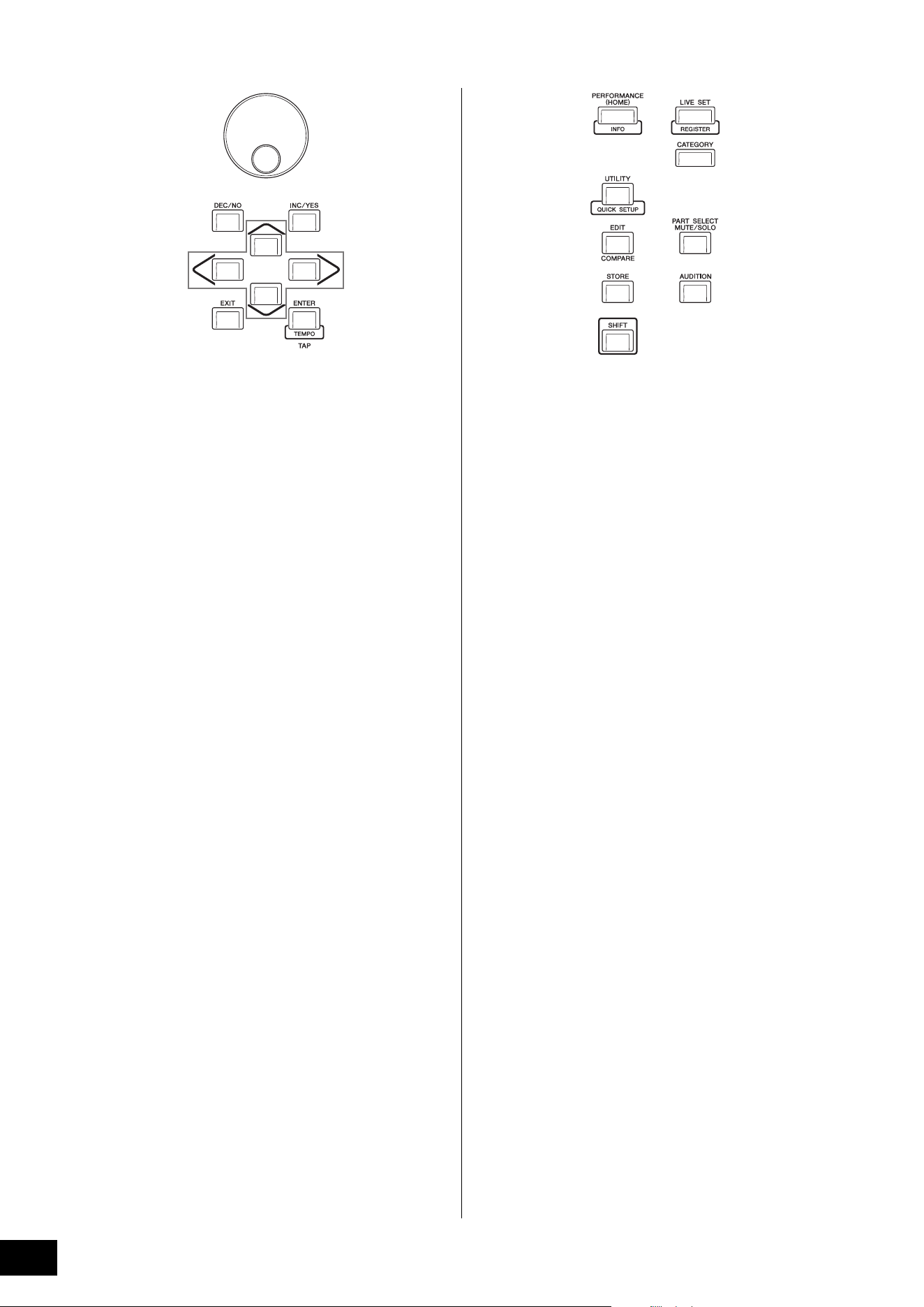
J Data dial
For editing the currently selected parameter. To increase the
value, turn the dial right (clockwise); to decrease the value,
turn the dial left (counter-clockwise). If a parameter with a
wide value range is selected, you can change the value in
broader strokes by quickly turning the dial.
K [DEC/NO] button
For decreasing the value of the currently selected parameter
(DEC: decrement). This button can also be used to cancel a
Job or Store operation.
Simultaneously hold down the [SHIFT] button and press the
[DEC/NO] button to quickly decrease the parameter value in
10-step jumps.
L [INC/YES] button
For increasing the value of the currently selected parameter
(INC: increment). This button can also be used to execute a
Job or Store operation.
Simultaneously hold down the [SHIFT] button and press the
[INC/YES] button to quickly increase the parameter value in
10-step jumps.
M Cursor buttons
The cursor buttons move the “cursor” around the display,
highlighting and selecting the various parameters.
N [EXIT] button
The menus and displays of the MODX+ are organized
according to a hierarchical structure. Press this button to exit
from the current display and return to the previous level in
the hierarchy.
O [ENTER] button
Use this button to call up the display of the selected menu,
or to execute a Job or Store operation.
Simultaneously hold down the [SHIFT] button and press the
[ENTER] button to call up the Tempo Settings display.
P [PERFORMANCE (HOME)] button
Use this button to return to the Performance Play display.
The button fully lights when the Performance Play display is
shown. This button lights dimly when the Utility display is
shown.
When the Performance Play display is shown and the cursor
is on the Performance Name, pressing this button shows or
hides the detailed information, which is the same information
you can access by touching the [View] button on the Screen.
Simultaneously hold down the [SHIFT] button and press the
[PERFORMANCE (HOME)] button to call up the Overview
display.
Q [UTILITY] button
Use this button to call up the Utility display for making overall
system settings. The button fully lights when the Utility
display is shown and the button lights dimly when other
displays are shown.
Simultaneously hold down the [SHIFT] button and press the
[UTILITY] button to call up the Quick Setup display.
Pressing this button while holding down the [PART SELECT
MUTE/SOLO] button opens the Touch Panel Calibration
display.
R [EDIT] button
Use this button to call up the display for editing
Performances (page 22) and Live Sets (page 35). Also,
pressing this button while editing Performance parameters
lets you switch between the just-edited sound and its
original, unedited condition, allowing you to hear how your
edits affect the sound (Compare function). The button lights
when the edit display is shown and the button flashes while
Compare is active.
S [STORE] button
Use this button to call up the Store display. The button fully
lights when the Store display is shown and the button lights
dimly when other displays are shown.
T [SHIFT] button
Pressing this button along with another button enables you
to execute various commands. For details, refer to the “Shift
Function List” (page 62).
J
KL
M
NO
P
c
Q
R
S
T
a
d
b
MODX+ Owner’s Manual
15
Controls and Functions
a [LIVE SET] button
Use this button to store all your favorite, often-used
Performances in a single, easy-to-access location and call
them up.
Simultaneously hold down the [SHIFT] button and press the
[LIVE SET] button to call up the Live Set display for storing
the currently selected Performance to the Live Set. This is
one more useful way you can quickly switch among
Performances you need in live performance situations.
The button fully lights when the Live Set display is shown. If
the Live Set display is not shown, the button lights dimly
when the Live Set function is active and the button’s lamp is
off when the function is NOT active.
b [CATEGORY] button
The Category Search function (page 24) can be accessed
by using this button.
Use this button while the Performance Play display is shown
to call up the Performance Category Search display for
selecting the entire Performance. When the cursor is on the
Part name in the Performance Play display, simultaneously
hold down the [SHIFT] button and press the [CATEGORY]
button to call up the Part Category Search display, allowing
you to select a sound type for the currently selected Part.
The button fully lights when the Category Search display is
shown. If the Category Search display is not shown, the
button lights dimly when the Category Search function is
active and the button’s lamp is off when the function is NOT
active.
c [PART SELECT MUTE/SOLO] button
Use this button to select a Part or to turn Mute or Solo ON or
OFF. Pressing this button while in the Performance Play
display opens the Part Select window.
The letter “M” is shown for the Muted Part, and the letter “S”
is shown for the Soloed Part.
To close the Part Select window, press the button again or
touch the “x” mark on the Screen.
The button lights up fully while the Part Select window is
shown on the screen, and the button lights dimly when the
Part Select window is not shown. The button is turned off in
the Utility display or Live Set display, or any other displays
that do not require Part Select.
d [AUDITION] button
Use this button (in the Performance Play, Live Set, or
Category Search displays) to play back or stop a sample
phrase showcasing the selected Performance sound. This
sample phrase of the Performance is called the “Audition
phrase.” The button fully lights when it is ON and the button
lights dimly when the Audition function is active such as in
the Category Search display.
This button also lets you lock/unlock the panel control to
prevent accidental or unwanted operations during
performance. To use this function, hold down the [SHIFT]
button and press this button simultaneously, while the
Performance Play display or the Live Set display is shown.
NOTE
While panel control is locked, only certain operations (keyboard,
pedals, MASTER VOLUME, Super knob, Pitch Bend wheel, panel
unlock) are possible. All other operations, including touch panel
operations, are disabled.
Button Operations
1–8 Shows Parts 1–8
9–16 Shows Parts 9–16
Select Switches to the Part Selection display
Mute Switches to the Mute Setting display
Solo Switches to the Solo Setting display
MODX+ Owner’s Manual
16
Controls and Functions
Rear Panel
FC3
FC4
FC5
FC4
FC5
FC7
12
3
4 5 6 87 9
)
Left side of Rear Panel
Right side of Rear Panel
Computer
USB flash drive
External MIDI keyboard
Powered
speakers
Headphones
Playback
equipment
Microphone
The illustration shows the MODX8+, but the information applies to all models.
External MIDI keyboard

MODX+ Owner’s Manual
17
Controls and Functions
Left side of Rear Panel
1 [USB TO HOST] terminal
Used to connect this instrument to a computer via a USB
cable, and allows you to transfer MIDI data and audio data
between the devices. Unlike MIDI, USB can handle multiple
ports via a single cable (page 56). For information about
how the MODX+ handles Ports, see page 56.
NOTE
Audio data sending capability for this instrument is a maximum
10 channels (5 stereo channels). Audio data receiving capability is a
maximum 4 channels (2 stereo channels).
2 [USB TO DEVICE] terminal
Used to connect this instrument to a USB flash drive
(page 61), or an external MIDI device (page 54).
Connecting a USB flash drive lets you save data created on
this instrument to the drive and load data from the drive to
the instrument. Save/Load operations can be performed:
[UTILITY] [Contents] [Store/Save] or [Load].
NOTE
• No other USB devices (such as a hard disk drive, CD-ROM drive
and USB hub) can be used.
• The instrument supports the USB 1.1 to 3.0 standard. However,
note that the transfer speed differs depending on the data type
and the condition of this instrument.
Right side of Rear Panel
3 MIDI [IN], [OUT] terminals
MIDI [IN] is for receiving control or performance data from
another MIDI device, such as an external sequencer, letting
you control this instrument from the connected separate
MIDI device.
MIDI [OUT] is for transmitting all control, performance and
playback data from this instrument to another MIDI device,
such as an external sequencer.
When the “MIDI IN/OUT” setting (page 54) is “USB,” these
terminals can be used for connecting an external MIDI
device to your computer (page 56).
4 FOOT SWITCH [ASSIGNABLE]/[SUSTAIN]
jacks
For connection of a separately sold FC3/FC4/FC5 Footswitch
to the [SUSTAIN] jack and a FC4/FC5 Footswitch to the
[ASSIGNABLE] jack. When connected to the [SUSTAIN]
jack, the Footswitch controls sustain. When connected to
[ASSIGNABLE], it can control one of various assignable
functions.
NOTE
• The term “FC3” in this Owner’s Manual refers collectively to the
FC3 and other footswitches compatible with the FC3, such as the
FC3A.
• The term “FC4” in this Owner’s Manual refers collectively to the
FC4 and other footswitches compatible with the FC4, such as the
FC4A.
5 FOOT CONTROLLER [1]/[2] jacks
For connection of a separately sold foot controller (FC7,
etc.). This jack lets you continuously control one of various
different assignable functions for Part edit—such as volume,
tone, pitch, or other aspects of the sound (see the Reference
Manual PDF document).
6 OUTPUT [L/MONO] and [R] jacks
Line level audio signals are output via these standard phone
jacks. For monophonic output, use only the [L/MONO] jack.
7 [PHONES] (Headphone) jack
This standard stereo phones jack is for connection to a set of
stereo headphones. This jack outputs audio signals identical
to those from the OUTPUT [L/MONO] and [R] jacks.
8 A/D INPUT [L/MONO]/[R] jacks
External audio signals can be input via these phone jacks
(1/4" mono phone plug). Various devices such as a
microphone, CD player or synthesizer can be connected to
these jacks and their audio input signal can be sounded as
the Audio Part.
In addition, you can use the special Vocoder feature by
connecting a microphone to this [L/MONO] jack and
inputting your voice to the microphone.
You can also use the Envelope Follower and ABS (Audio
Beat Sync) features. Envelope Follower is a function for
detecting the volume envelope of the input signal waveform
and modifying sounds dynamically.
NOTE
• A guitar or bass having active pickups can be directly connected.
However, when using passive pickups, connect the instrument via
an effect device.
• The Vocoder/Envelope Follower can be controlled from all Part
outputs, and not just the A/D INPUT [L/MONO]/[R] jacks.
ABS (Audio Beat Sync) is a function for detecting the beat of
the audio signal input from these jacks and synchronizing
the beat with the Motion Sequencer or Arpeggio.
Use 1/4" mono phone plugs. For stereo signals (such as from
audio equipment), use the [L/MONO]/[R] jacks. For mono
signals (such as from a microphone or guitar), use only the
[L/MONO] jack.
For details about the Envelope Follower and ABS features,
see the Reference Manual PDF document.
9 [P] (Standby/On) switch
Press to set the power to On or Standby.
) [DC IN]
Plug the AC adaptor supplied with this instrument.
MODX+ Owner’s Manual
18
Power Supply
Connect the supplied AC adaptor in the following order.
1 Make sure the [P] (Standby/On) switch on
the instrument is set to the Standby
(N)
position.
2 Wrap the DC output cable of the AC adaptor
around the cable clip (as shown below), and
then connect the plug of the adaptor to the
DC IN jack on the rear panel.
NOTE
Use of the cable clip prevents accidental unplugging of the
cable during operation. Make sure to avoid tightening the cord
more than necessary or pulling on the cord strongly while it is
wrapped around the cable clip to prevent wear on the cord or
possible breakage of the clip.
3 Connect the other end of the AC adaptor to
an AC outlet.
NOTE
Reverse the order of the instruction steps above when disconnecting
the AC adaptor.
WARNING
• Use the specified AC adaptor (page 71) only. Using the wrong
AC adaptor can result in damage to the instrument or
overheating.
• When using the AC adaptor with
a removable plug, make sure to
keep the plug attached to the AC
adaptor. Using the plug alone can
cause electric shock or fire.
• Never touch the metallic section
when attaching the plug. To avoid
electric shock, short circuit or
damage to avoid electric shock,
short circuit or damage. Also, be
careful that there is no dust
between the AC adaptor and
plug.
CAUTION
• When setting up the product, make sure that the AC outlet you
are using is easily accessible. If some trouble or malfunction
occurs, immediately turn the power off and disconnect the
plug from the outlet.
• The instrument remains charged and draws a small amount of
power even when the [P] (Standby/On) is set to the Standby
position. For this reason, if you intend not to use it for an
extended period of time, make sure to unplug the power cord
from the wall outlet.
Connecting Speakers or Headphones
Since the instrument has no built-in speakers, you will need
to monitor the sound of the instrument by using external
equipment. Connect a set of headphones, powered
speakers, or other playback equipment as illustrated below.
When making connections, be sure that your cables have
the appropriate ratings.
Powering Up the System
Make sure the volume settings of the instrument and external
devices such as powered speakers are turned to the
minimum before turning the power on. When connecting the
instrument to powered speakers, turn on the power switch of
each device in the following order.
When turning the power on:
First, the instrument (the display will turn on and the buttons
will light), then the connected powered speakers.
When turning the power off:
First, the connected powered speakers, then the instrument
(the display will turn off and the buttons will turn off).
Keep in mind that the [P] (Standby/On) switch is located at
the left side (from the view of the keyboard) of the DC IN
socket on the rear panel of the instrument.
Setting Up
Cable clip
Be careful not to bend
the connector
2
3
DC IN jack (page 16)
AC outlet
AC adaptor
Plug
Slide the plug as indicated.
The shape of the plug differs
depending on your area.
Powered speaker (left)
Powered speaker (right)
Headphones
OUTPUT L/MONO OUTPUT R
PHONES
DC IN
[P] (Standby/On) switch
MODX+ Owner’s Manual
19
Setting Up
Auto Power Off function
To prevent unnecessary power consumption, this instrument
features an Auto Power Off function that automatically turns
the power off if the instrument is not operated for a specified
period of time.
Auto Power Off Setting
The amount of time that elapses before the power is
automatically turned off can be set.
Disabling Auto Power Off (simple method)
Turn the power on while holding down the lowest key on the
keyboard. An “Auto power off disabled” message appears
briefly and Auto Power Off is disabled. The setting is retained
even if the power is turned off.
NOTICE
• Even when the power is turned off, electricity is still flowing to
the instrument at the minimum level. To shut off the electricity
completely, make sure you unplug the power cord from the
wall AC outlet.
• Depending on the instrument status, the power may not turn
off automatically, even after the elapse of the specified period
of time. Always turn off the power manually when the
instrument is not in use.
• When the instrument is not operated for a specified period of
time while connected to an external device such as an
amplifier, speaker or computer, make sure to follow the
instructions in the Owner’s Manual to turn off the power to the
instrument and the connected devices in the proper sequence,
in order to protect the devices from damage. If you do not
want the power to turn off automatically when a device is
connected, disable Auto Power Off.
• The setting will revert to its default value if not backed up
before the power is turned off.
• When Auto Power Off is set to “off,” the value will be retained
even if the backup data saved on another device is loaded to
the instrument. When Auto Power Off is set to something other
than “off,” the value will be overwritten with loaded data.
NOTE
• The setting time is approximate.
• To turn the power on after Auto Power Off has been executed,
press the [P] (Standby/On) switch to set the switch to the
Standby (N) position and press it again to turn ON.
• When the factory settings are restored, the setting is changed to
the default value (off).
Restoring the initial factory
settings (Initialize All Data)
NOTICE
When the Initialize All Data operation is executed, all the
Performance, Song, and any system settings you created on the
Utility display will be erased. Make sure you are not overwriting
any important data. Be sure to save all important data to your
USB flash drive before executing this procedure (page 60).
1 Press the [UTILITY] button or touch the
UTILITY icon in the upper right of the screen
to call up the Utility display.
2 Touch the [Settings] tab in the left of the
screen and then touch the [System] tab.
The entire system setting display appears.
3 Touch [Initialize All Data] in the lower right of
the screen.
The display prompts you for confirmation. To cancel this
operation, touch the [Cancel No] in the screen or press
the [DEC/NO] button on the panel.
4 Touch [Yes] in the screen or press the [INC/
YES] button to execute the Initialize All Data
operation.
Instructions:
[UTILITY] [Settings] [System] [Auto
Power Off]
Setting Value (min.):
off (disables Auto Power Off), 5, 10, 15, 30,
60, 120
Default Setting (min.):
off
MODX+ Owner’s Manual
20
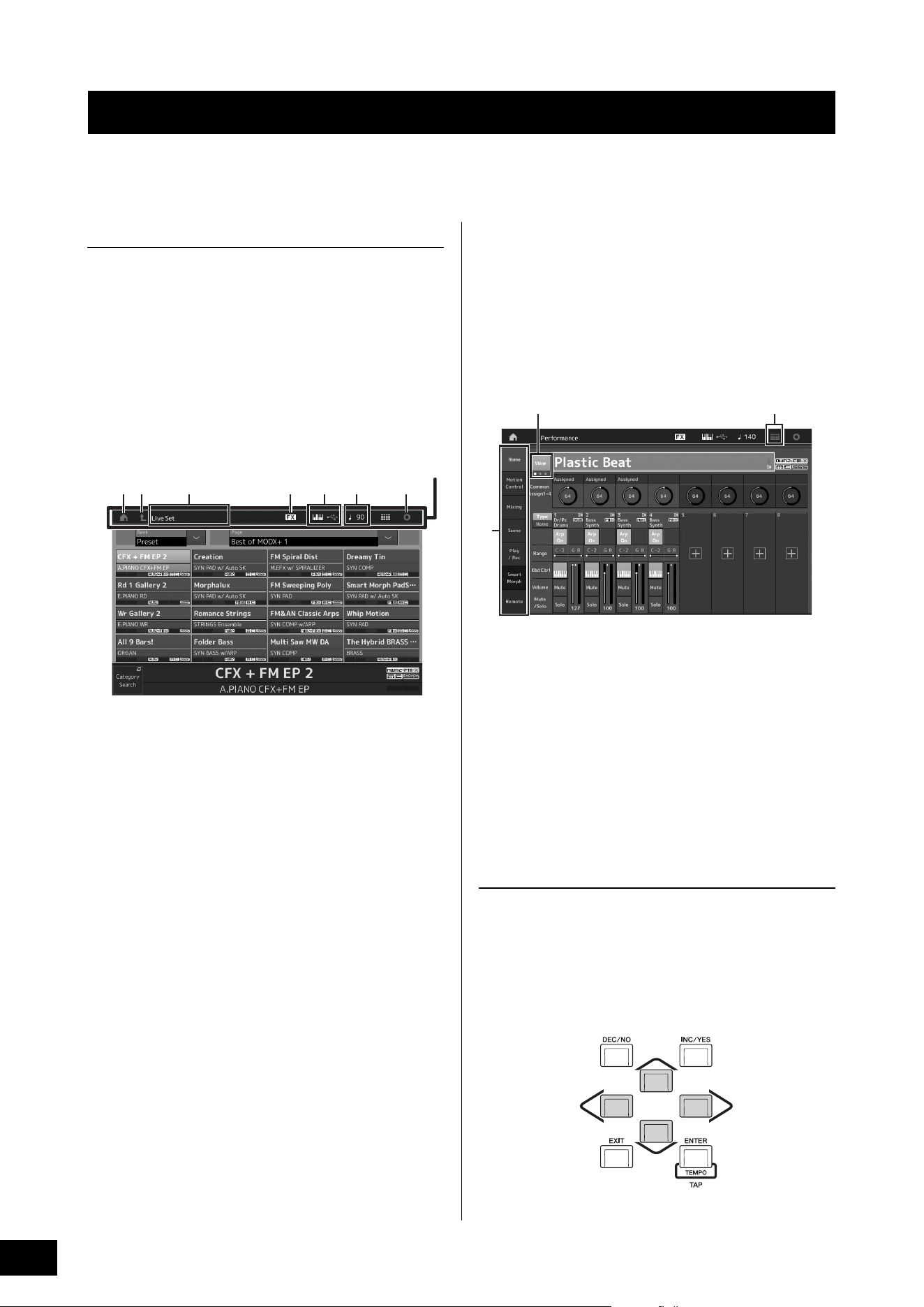
The MODX+ features a convenient touch panel display. You can operate various settings and select desired parameters by
directly touching the screen. Furthermore, you can use the data dial and other buttons for display operations.
Display (touch panel) configuration
This section explains the navigation bar and the display
selecting tabs which are common to all types of displays. For
the purpose of illustration, the Live Set display which
MODX+ appears when the MODX+ is turned on and the
Performance Play display (Home display) are used as
examples.
NOTE
You can change the start-up display (the display that first appears
when the power is turned on). For details about the setting, see
page 51.
Live Set display
1 HOME icon
Moves to the Performance Play display.
2 EXIT icon
Functions same as the [EXIT] button on the panel. Press
this icon to exit from the current display and return to the
previous level in the hierarchy.
3 INFORMATION area
Displays helpful information, including the currently
selected display name.
4 EFFECT icon
Touch the icon to call up the Effect switch display. The
icon turns off when any of the Effect blocks (Insertion,
System or Master) is off.
5 QUICK SETUP icon
Displays the settings of Local Control ON/OFF and MIDI
IN/OUT.
The keyboard-shaped icon lights up when Local Control
is set to ON and turns off when Local Control is set to
OFF.
When MIDI is set as the MIDI IN/OUT setting, a MIDI
connector-shaped icon appears. When USB is set as the
MIDI IN/OUT setting, a USB connector-shaped icon
appears.
Touch the desired icon to call up the corresponding
quick setup display.
6 TEMPO SETTINGS icon
Displays the tempo of the currently selected
Performance. Touch the icon to call up the Tempo
settings display.
7 UTILITY icon
Touch the icon to call up the last opened display among
the Utility displays.
Performance Play display (Home display)
8 LIVE SET icon
Touch the icon to call up the Live Set display.
9 Display selecting tabs
Touch the desired tab to call up the corresponding
display.
) View button
Determines whether the detailed information of each Part
is displayed (On) or not displayed (Off). The displayed
information differs depending on the cursor position or
the Slider function settings.
Moving the cursor
Use these four buttons to navigate the display, moving the
cursor around the various selectable items and parameters
in the screen. When selected, the relevant item is highlighted
(the cursor appears as a dark block with inverse characters).
You can change the value of the item (parameter) at which
the cursor is located by using the data dial, [INC/YES] and
[DEC/NO] buttons.
Basic Operation and Displays
1 2 76543
Navigation bar
9
8)
MODX+ Owner’s Manual
21
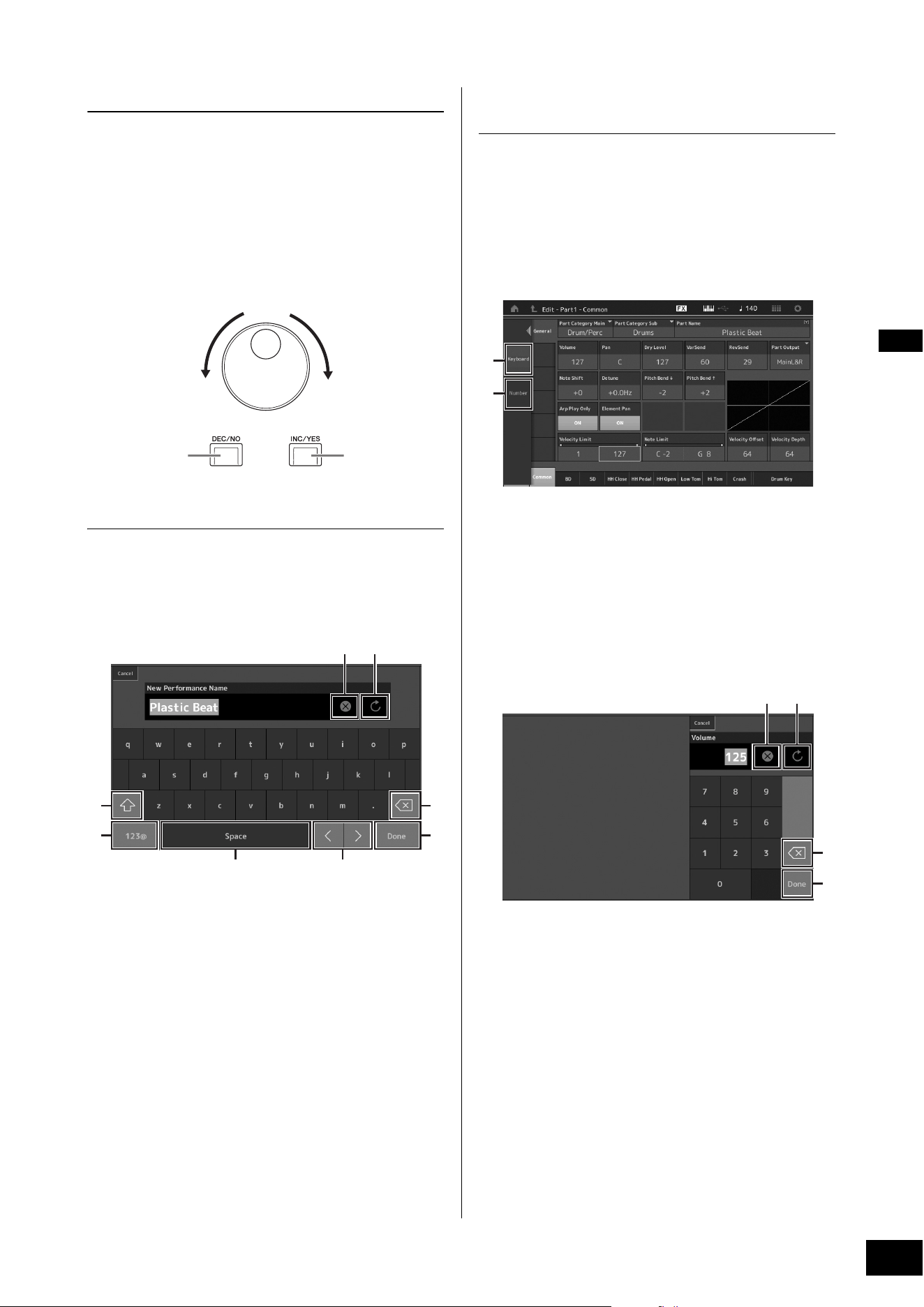
Changing (editing) parameter values
Rotating the Data dial to the right (clockwise) increases the
value, while rotating it to the left (counter-clockwise)
decreases it.
Pressing the [INC/YES] button increases a parameter value
by one step, and pressing [DEC/NO] button decreases it.
For parameters with large value ranges, you can increase
the value by 10 by simultaneously holding down the [SHIFT]
button and pressing the [INC/YES] button. To decrease by
10, simultaneously hold down the [SHIFT] button and press
the [DEC/NO] button.
Naming (inputting characters)
You can freely name the data you’ve created, such as
Performances, Songs, and files saved to a USB storage
device. Touch the Naming parameter or move the cursor to
the Naming parameter and press the [ENTER] button to call
up the input character display.
1 Deletes all characters.
2 Reverts to the default name.
3 Switches between uppercase and lowercase
alphabetical characters.
4 Calls up the display for entering numbers, punctuation
marks and miscellaneous characters.
5 Inserts a space (blank) at the cursor position. (You can
also use the [INC/YES] button for the same operation.)
6 Moves the cursor position.
7 Deletes the previous character (backspace). (You can
also use the [DEC/NO] button for the same operation.)
8 Completes the text input and closes the display.
Inputting using the keys on the
keyboard and numeric keypad display
For some parameters, you can also enter the value directly,
using the LCD as a numeric keypad or using keys on the
keyboard. Input via the keys is activated for the parameters
where the numerical values should be entered. Input via the
numeric keypad display is activated when inputting values.
Touch the desired parameter or move the cursor to the
parameter and press the [ENTER] button to call up the
display having the two menus (shown below).
1 Enables keyboard input.
You can play any note on the keyboard and the note or
velocity are input.
2 Enables numeric keypad input.
You can input a number directly by using the numeric
keypad. You can also use the data dial, the [INC/YES]
button, and the [DEC/NO] button to increase and
decrease the input number.
Numeric keypad display
3 Erases all numbers.
4 Restores the value to the last setting.
5 Deletes the last digit of the number.
6 Completes the input operation and closes the numeric
keypad display.
Increases numberDecreases number
Increases number
Decreases number
3
4
21
5 6
7
8
1
2
43
5
6
MODX+ Owner’s Manual
22
The MODX+ has 16 Parts and basic musical instrument
sounds are assigned to each Part. A single set of these
sounds is called a “Performance.” You can change sounds
as desired by selecting the appropriate Performance.
There are three Part types as follows.
Normal Parts (AWM2)
Normal Parts (AWM2) are mainly pitched musical instrument
type sounds (piano, organ, guitar, synthesizer, etc.) that can
be played over the full range of the keyboard.
Normal Parts (FM-X)
Normal Parts (FM-X) are powerful FM Synthesis system
sounds. This sound is played conventionally from the
keyboard, with standard pitches sounding for each key.
Drum Parts
Drum Parts are mainly percussion/drum sounds that are
assigned to individual notes.
Performances can also be divided into two groups as
follows.
Single Part Performances
A Single Part Performance contains only one Part. Select this
if you want to play a single instrument.
Multi Part Performances
A Multi Part Performance contains multiple Parts. Select this
if you want to play sounds of multiple instruments by using
layering and splitting functions.
This instrument features Banks for memorizing
Performances. There are basically four different types of
Banks: Preset, User, Library, and GM. The contained
Performances and features depend on the Bank as
described below.
Preset Banks
The Preset Banks contain a full set of specially programmed
Performances. Performances you’ve edited yourself cannot
be saved in the Preset Banks.
User Banks
The User Banks contain the Performances you have edited
and stored. The User Banks are initially empty.
NOTICE
If a Performance in a User Bank (User Performance) is
overwritten or replaced, that User Performance will be lost. When
you store an edited Performance, be careful not to overwrite any
important User Performances.
Library Banks
The Library Banks contain the Performances you have
added as Libraries. The Library Banks are initially empty.
(A Library can be added by importing a library file.)
GM Bank
The GM Bank contains the Parts allocated according to the
GM standard.
Each of these Banks include Performances organized
according to the Performance type.
NOTE
• For details about Performances, refer to “Basic Structure” in the
Reference Manual PDF document.
• For lists of the Performances, refer to the separate Data List PDF.
Selecting Performances
Multiple
Performances
One Performance
Part 1 (Piano)
Part 2 (Guitar)
Part 3 (Bass)
Part 4 (Drum)
Part 16
GM
GM (General MIDI) is a worldwide standard for Voice
organization and MIDI functions of synthesizers and tone
generators. It was designed primarily to ensure that any
song data created with a specific GM device would sound
virtually the same on any other GM device—no matter the
manufacturer or the model. The GM bank on this
synthesizer is designed to appropriately play back GM
song data. However, keep in mind that the sound may not
be exactly the same as played by the original tone
generator.
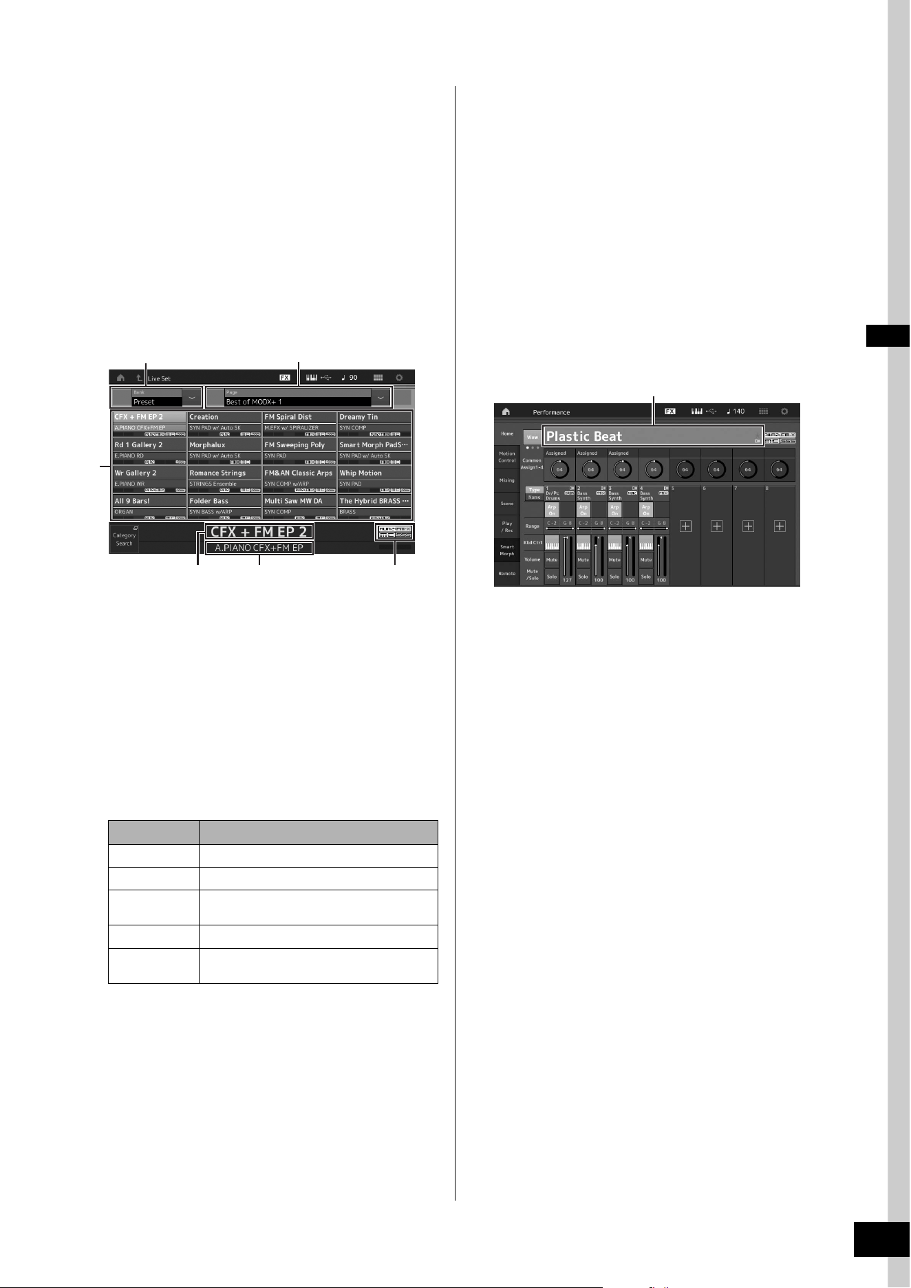
MODX+ Owner’s Manual
23
Selecting Performances
When you turn on your instrument for the first time, a Live Set
of the Preset Banks will be displayed in the top display. The
Live Set is a list in which Performances can be freely
arranged. Up to 16 Performances can be arranged over a
single page. You can play various Performances selected
from the Preset Live Sets.
Selecting a Performance from the
Live Set
1 Press the [LIVE SET] button.
This calls up the Live Set display.
1 Page (switched by pressing [u] [d] in the screen)
NOTE
You can also use [SHIFT] and [INC/DEC] or [SHIFT] and [DEC/
NO] for switching pages.
2 Preset Bank/User Bank (switched by pressing the
[u] [d] in the screen)
3 Performance list
4 Active Performance names
5 Slot name
6 Flag (see chart below)
NOTE
• “Seamless Sound Switching” is a feature that lets you switch
Performances smoothly without any notes being cut off. The
SSS feature is available for all Preset Bank Performances in
this instrument. However, SSS is available only for the
Performance containing Parts 1–4, not for the Performance
with using Parts 5–16.
• When the background of “FM-X” flag display is a gradient, it
indicates that the Performance has the Smart Morph
information. The Smart Morph is a function that allows you to
smoothly morph the FM-X sound between multiple FM-X
sounds, using machine learning. For details, refer to the
Reference Manual.
2 Touch the desired Performance on the
screen.
NOTE
To rearrange the order of the Performances registered in the Live
Set, see page 35.
3 Play the keyboard.
Switching Performances
1 Press the [PERFORMANCE (HOME)] button.
The Performance Play display appears, and the current
Performance name is shown.
2 Move the cursor to the Performance name
and select the desired Performance by using
the data dial, the [INC/YES] button, or the
[DEC/NO] button.
NOTE
• To quickly move forward through the Performance numbers in
10-step jumps, simultaneously hold down the [SHIFT] button
and press the [INC/YES] button.
• To decrease by 10, do the opposite; simultaneously hold
down the [SHIFT] button and press the [DEC/NO] button.
3 Play the keyboard.
Flag Definition
AWM2 Performance comprised only of AWM2 Parts
FM-X Performance comprised only of FM-X Parts
AWM2+FM-X Performance comprised of both AWM2 and FM-
X Parts
MC Performance featuring Motion Control
SSS Performance featuring Seamless Sound
Switching
1
2
5 6
3
4
Performance name

MODX+ Owner’s Manual
24
Selecting Performances
Using the Category Search
function
The Performances are conveniently divided into specific
Categories, irrespective of their bank locations. The
categories are divided based on the general instrument type
or sound characteristics. The Category Search function
gives you quick access to the sounds you want.
1 Press the [CATEGORY] button while the
Performance Play display is shown.
This calls up the Category Search display.
NOTE
You can open the Category Search display by selecting
[Category Search] from the menu that is called up when the
Performance name is touched.
1 Bank
2 Attribute
NOTE
Attributes are Performance properties and sorted according
to tone generator types or parts of Performances.
3 Keyword search
4 Main categories
5 Sub categories
6 Performance list of the selected category
NOTE
The selected Performance is displayed in white,
Performances with a single part are in green, and
Performances with multi parts are in blue.
7 For changing the sorting order
8 For changing the Performance list page
9 Adding to or deleting from the Favorite List
2 Touch and select the desired main category
(
4).
NOTE
• You can filter the Performance lists by touching [Bank] (1)
and selecting the desired bank type from the list.
• You can also filter the Performance lists by touching [Attribute]
(2) and selecting the desired attribute type from the list.
• You can also call up your own favorite Performances instantly.
To enable this, touch [Set] (9) on the screen and bookmark
your favorite Performances beforehand.
3 Touch and select the desired sub category
(
5).
This calls up the Performance lists of the selected
category (6).
4 Touch the desired Performance.
5 Touch the HOME icon or EXIT icon to actually
call up the selected Performance.
This closes the Category Search display.
NOTE
You can also use the [ENTER] button, the [EXIT] button, or the
[PERFORMANCE (HOME)] button to finalize the selection.
Below is a list of the Categories and their panel
abbreviations.
6 Play the keyboard.
6
4
5
1 2 3
7 89
Abbreviation Category
Piano Piano
Keyboard Keyboard instruments (Harpsichord, Clav,
etc.)
Organ Organ
Guitar Guitar
Bass Bass
Strings Strings
Brass Brass
Woodwind Woodwind instruments
Syn Lead Synth Lead
Pad/Choir Synth Pad
Syn Comp Synth Comp
Chromatic Perc Chromatic Percussion (Marimba,
Glockenspiel, etc.)
Drum/Perc Drum/Percussion
Sound FX Sound Effect
Musical FX Musical Effect
Ethnic Ethnic
No Assign No Assign
Init Initialize
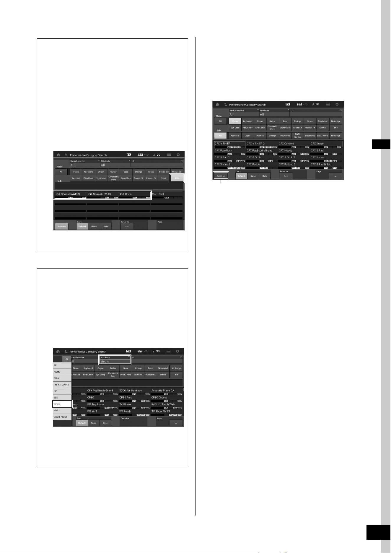
MODX+ Owner’s Manual
25
Selecting Performances
Playback Audition phrase
You can hear a sample of Performance sounds. The sample
sound is referred to as “Audition phrase.”
1 Touch [Audition] in the Category Search
display.
The sample of the currently selected Performance plays.
If you select a different Performance during Audition
phrase playback, the audition phrase switches to that of
the newly selected Performance.
2 Touch [Audition] again to stop playback.
NOTE
• You can also playback/stop the Audition phrase by pressing
the [AUDITION] button on the front panel.
• You can playback/stop the Audition phrase by pressing the
[AUDITION] button on the front panel while the Performance
display or the Live Set display is shown.
Selecting an Initialized Performance
Follow the steps below to select an Initialized
Performance.
1 Touch [Init] of the main category in the
Category Search display.
2 Only initialized Performances are
displayed in the Performance list.
The Initialized Performances are divided into three
categories: [Init Normal (AWM2)] for the normal
Parts (AWM2), [Init Normal (FM-X)] for the normal
Parts (FM-X), and [Init Drum] for the Drum Parts.
3 Select the desired Performance.
Selecting only Single Part Performances
You can filter out the Single Part Performances by using
the Attribute function.
1 Touch [Attribute] in the Category Search
display.
2 Touch [Single] from the menu in the left
of the screen.
3 Only Single Part Performances are
displayed in the Performance list, letting
you select the desired one.
[Audition]
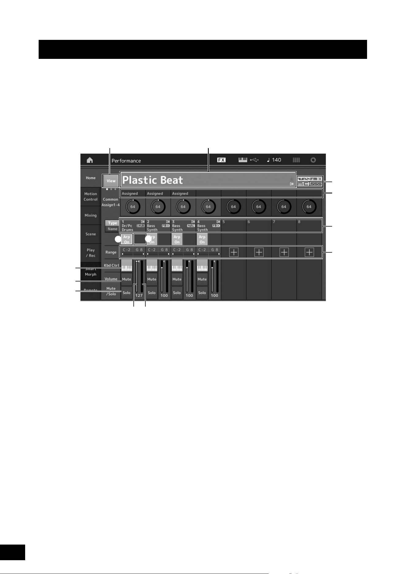
MODX+ Owner’s Manual
26
You can mix several different parts together in a layer, or split them across the keyboard, or even set up a combination layer/
split. Each Performance can contain up to eight different Parts. Press the [PERFORMANCE (HOME)] button before playing the
keyboard.
Performance Play display
In this condition, playing the keyboard sounds the Performance indicated in the display. The parameters shown in the
Performance Play display are briefly explained below. You can operate the icons by touching on the display.
1 Performance name
2 Flag
3 Functions assigned to knobs
4 Part names
5 Switching Motion Sequencer on/off for Parts
6 Switching Arpeggio on/off for Parts
7 Note Limit for Parts
8 Switching Keyboard Control on/off for Parts
9 Switching Mute on/off for Parts
) Switching Solo on/off for Parts
! Volume of Parts 1–8
@ Meter (Audio Output Level)
# Showing or hiding detailed information on each Part
Playing the Keyboard
1#
!@
3
2
4
7
8
9
)
5
6
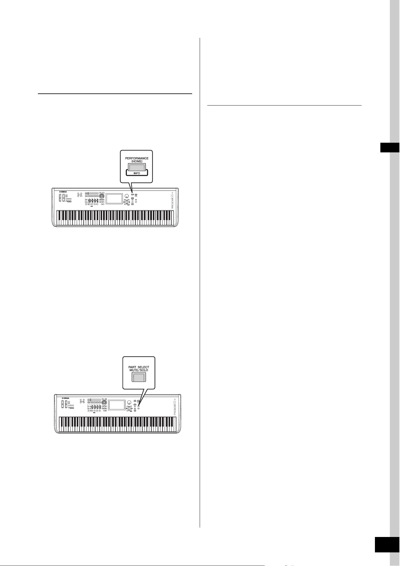
MODX+ Owner’s Manual
27
Playing the Keyboard
Switching a Part on/off
You can turn the eight Parts of the current Performance on or
off as desired.
Turning specific Parts on/off (Mute
function)
You can turn individual Parts on/off by using the Mute
function.
1 Press the [PERFORMANCE (HOME)] button.
The button lamp lights, indicating that each Part can be
turned on/off.
2 Touch the [MUTE] button on the screen to
mute the Part.
Touch the same button again to turn the button off and
disengage the mute function for that Part. You can turn
multiple Parts on/off by touching their buttons.
You can also mute parts by using the [PART SELECT MUTE/
SOLO] button with the operation below.
1 While the Performance display is shown,
press the [PART SELECT MUTE/SOLO]
button.
The Part Select Windows appears on the display.
2 Touch the [MUTE] button on the Part Select
Window to turn the button on.
3 Touch the number button for the Part you
wish to mute. The letter “M” appears on the
button, and the corresponding Part will be
muted.
You can turn multiple Parts on/off by pressing multiple
buttons.
4 To disengage the mute function, with “MUTE”
selected, touch the button with the letter “M”
shown on it.
The “M” indication disappears and the Mute function is
disengaged.
Soloing a specific Part (Solo function)
The Solo function is the opposite of Mute, and lets you
instantly solo a specific Part and mute all others.
1 Press the [PERFORMANCE (HOME)] button.
2 Touch the [SOLO] button on the screen to
solo the Part.
The [SOLO] button lights, indicating that Solo is enabled.
Touch the same button again turns the off the button to
disengages the solo function.
You can also solo a part by using the [PART SELECT MUTE/
SOLO] button with the operation below.
1 While the Performance display is shown,
press the [PART SELECT MUTE/SOLO]
button.
The Part Select Windows appears on the display.
2 Touch the number button for the Part you
wish to solo.
3 Touch the [SOLO] button on the Part Select
Window to turn the button on.
The letter “S” appears on the currently selected Part, and
the corresponding Part will be soloed.
4 To disengage the solo function, with “SOLO”
selected, touch the button with the letter “S”
shown on it.
The “S” indication disappears and the Solo function is
disengaged.
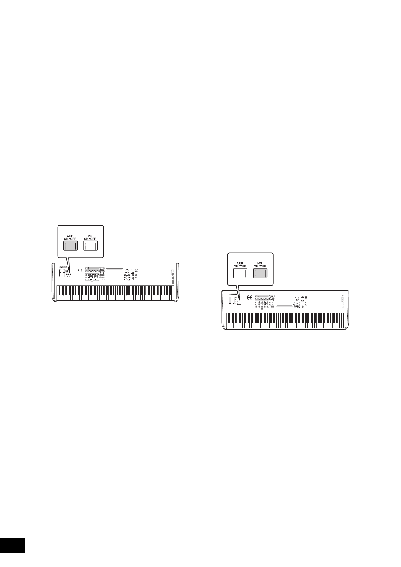
MODX+ Owner’s Manual
28
Playing the Keyboard
Using the Arpeggio function
This function lets you trigger rhythm patterns, riffs and
phrases using the current Part by simply playing notes on
the keyboard.
It not only provides inspiration and full rhythmic passages in
your live performances, but it gives you fully formed
instrumental backing parts of various music genres for ease
in creating songs.
You can assign the desired eight Arpeggio Types to each
Part and play back the Arpeggios of up to eight Parts
simultaneously.
You can also set the Arpeggio playback method, Note
range, Velocity range and Play Effects to create your own
original grooves.
NOTE
For details about Arpeggio, see the Reference Manual PDF
document.
Turning the Arpeggio on/off
To turn Arpeggio playback on or off, press the [ARP ON/
OFF] button on the panel.
For information on selecting a different Arpeggio type during
preparation or switching Arpeggios in the middle of your
performance, see “Using the Scene function” (page 34).
Using the Motion Sequencer
function
The powerful Motion Sequencer feature lets you dynamically
change sounds by operating Parameters depending on
sequences created in advance.
It provides real time control for changing sounds depending
on various sequences such as Tempo, Arpeggio, or the
rhythm of external connected devices.
You can assign up to eight desired Sequence types for one
Lane.
You can also set up to four Lanes corresponding to the
Motion Sequencer function for one Part. Up to eight Lanes
can be used at the same time for the entire Performance.
For the Motion Sequencer function, in addition to being able
to set the Arpeggio playback method, you can also set the
Velocity range, Play Effects, the amount of steps, and so on,
to create your own original grooves.
NOTE
For details about the Motion Sequencer, see the Reference Manual
PDF document.
Turning Motion Sequencer on/off
Press the [MS ON/OFF] button on the front panel to turn the
Motion Sequencer on/off.
For information on selecting a different Motion Sequence
type during preparation or switching Motion sequences in
the middle of your performance, see “Using the Scene
function” (page 34).
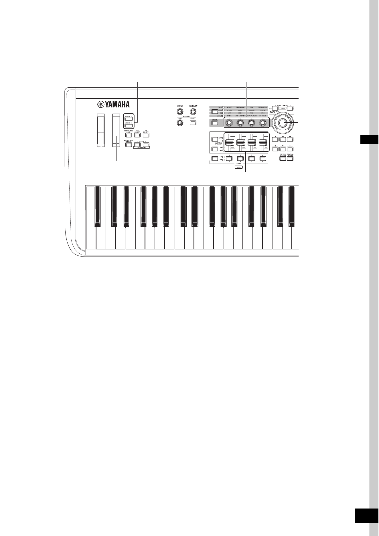
MODX+ Owner’s Manual
29
Using controllers to change the sound
The MODX+ gives you an amazing amount of control options. In addition to the conventional Pitch Bend and Modulation
Wheels, it also features an extensive array of special real time controls—including the Knobs, Super Knob, Control Sliders, and
Assignable Switch buttons.
Pitch Bend wheel
Modulation wheel
[ASSIGN 1]/[ASSIGN 2] buttons
Control Sliders
Knobs
Super Knob
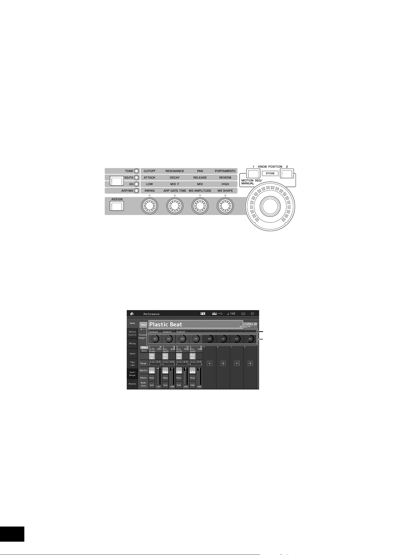
MODX+ Owner’s Manual
30
Playing the Keyboard
Using the Knobs to change the sound
Knobs 1–4 (5–8) let you adjust a variety of parameters for the current Performance or Part, such as effect depth, attack/release
characteristics, timbre, and others. The functions assigned to each Knob can be alternatively selected via the Knob Function
button or the [ASSIGN] button. There are basically two ways in which the sound can be controlled: controlling the entire
Performance or controlling the specific Part.
For controlling the entire Performance
Move the cursor to the desired Performance name from the Performance Play display. Or turn the [PART SELECT MUTE/
SOLO] button and select “Common” to enable the Performance Control status, and operate Knobs 1–4 (5–8).
For controlling the desired Part
Move the cursor to the desired Part name from the Performance Play display. Or turn the [PART SELECT MUTE/SOLO]
button and select any of the “1” to “16” buttons to enable the Part Control status, and operate Knobs 1–4 (5–8).
1 Press the Knob Function [TONE]/[EG/FX]/[EQ]/[ARP/MS] button or the [ASSIGN] button, so that the
button corresponding to the function you want to switch is lit.
1 [TONE]: Switches to functions related to sound settings
2 [EG/FX]: Switches to functions related to Envelope Generator (EG) and Effect settings
3 [EQ]: Switches to functions related to Equalizer (EQ) settings
4 [ARP/MS]: Switches to functions related to Arpeggio and Motion Sequencer settings
The functions currently assigned to the Knobs 1–4 (5–8) and the parameter values of the functions are shown.
2 Turn a desired knob while playing the keyboard.
The value of the corresponding parameter changes and the function/effect is applied to the sound.
1
2
3
4
Knob 1
Super Knob
Knob 2 Knob 3 Knob 4
Functions assigned to Knobs 1–4 (5–8).
The current values of the functions
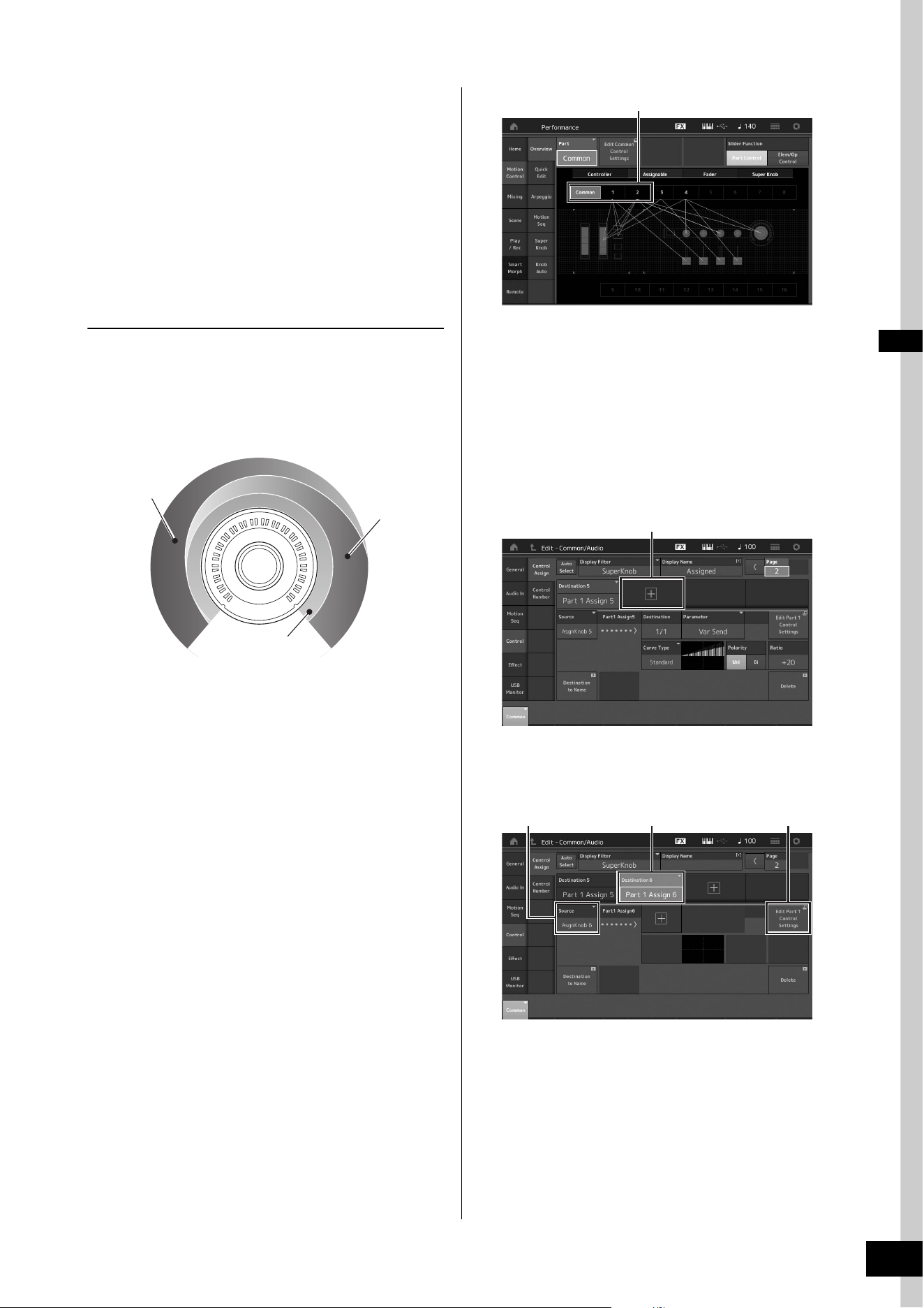
MODX+ Owner’s Manual
31
Playing the Keyboard
Using the Super Knob to change
the sound
The Super Knob lets you simultaneously control all
parameter values of the functions assigned to Knobs 1–4 (5–
8). You can create complex sounds by using the Super Knob
together with the Motion Sequencer.
The Super Knob is always active for use. You don’t have to
press the Knob Function button or the [ASSIGN] button
before using the Super Knob.
Setting Example for Super Knob
Here is an example of a Super knob setting for adding a
layer of a morphing sound to the preset Super Knob sound.
For the layer, select from two preset Performances-an
acoustic piano and a pad sound, for example-and create the
sound morph. This allows you to add even more complexity
to the preset Super Knob sounds.
Selecting Performances for the layer
1 Select the Performance for Part 1.
1-1
Press the [CATEGORY] button, and select “CFX
PopStudioGrand.”
2 Select the Performance for Part 2.
2-1
In the Performance Play display, select Part 2. Press
the [CATEGORY] button while holding down the
[SHIFT] button, and select “Ethereal.”
3 Check the current settings.
3-1
Touch the [Motion Control] tab and then the
[Overview] tab.
The Motion Control Overview display appears.
3-2 Touch Part [Common], then [1] and [2] to make sure
that no green lines are connected (in other words,
nothing is assigned) to Assignable Knobs 6 and 7.
To see the status of Knobs 5 to 8, press the
[ASSIGN] button as needed.
4 Set the instrument parameters for Part 1.
4-1
Touch the [Super Knob] tab.
The Motion Control Super Knob display appears.
4-2 Touch the [Edit Super Knob] button.
The Control Assign display for Common/Audio Edit
appears.
4-3 Touch the [+] button.
When the [+] button is not shown, touch the
[>] button to go to Page 2, and touch the [+] button.
Destination 6 is added.
4-4 On the [Destination 6] tab, set Source to “Asgn
Knob 6,” and [Destination6] to “Part 1 Assign 6.”
4-5 Touch the [Edit Part1 Control Settings] button.
The Control Assign display for Element Common
Edit appears.
4-6 Touch the [+] button.
When the [+] button is not shown, touch the
[>] button to go to Page 2, and touch the [+] button.
4-7 Touch the [Destination 10] tab, and select Volume
from Part Param.
Acoustic Piano
Pad sound
Preset
3-2
4-3
4-44-4 4-5
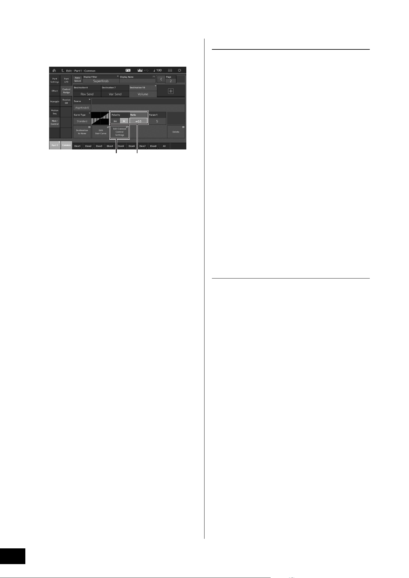
MODX+ Owner’s Manual
32
Playing the Keyboard
4-8 Adjust other parameters if necessary.
Here, set the Curve Polarity (Polarity) to “Bi,” and the
Curve Ratio (Ratio) to “+63.”
5 Set the instrument parameters for Part 2.
5-1
Touch the [Edit Common Control Settings] button.
The Control Assign display for Common/Audio Edit
appears.
5-2 Touch the [+] button.
Destination 7 is added.
5-3 On the [Destination 7] tab, set Source to “Asgn
Knob 7,” and [Destination 7] to “Part 2 Assign 7.”
5-4 Touch the [Edit Part 2 Control Settings] button.
Set the parameters the same as the ones for Part 1.
Here, set the Curve Polarity (Polarity) to “Bi,” and the
Curve Ratio (Ratio) to “-64.”
This completes the setting.
When further adjustments are needed
• Touch the [Edit Common Control Settings] button, and
switch between Destination 6 and 7, and adjust the
Curve Type or Ratio.
or
• Press KNOB POSITION [1], turn Knobs 6 and 7 to
make a setting for when the Super Knob is turned all
the way to the left, and simultaneously press [SHIFT]
and KNOB POSITION [1] to store the settings. Next,
press the KNOB POSITION [2], turn the knobs again to
make a setting for when the Super Knob is turned all
the way to the right, and simultaneously press [SHIFT]
and KNOB POSITION [2] to store the setting.
Checking the Super Knob settings
This section covers the procedure to check the parameter
values changed by operation of the Super Knob.
1 Press the [PERFORMANCE (HOME)] button.
The button lights, indicating that you can make common
settings for all Parts.
2 With the [View] button off, press the [ASSIGN]
button to select Common Assign 1–4 or
Common Assign 5–8.
The button lights when Assign 1–4 is selected, and the
button flashes when Assign 5–8 is selected.
The functions currently assigned to Knobs 1–4 (5–8) and
the parameter values are shown.
3 Turn the Super Knob while playing the
keyboard.
All relevant parameter values are simultaneously
changed and all assigned functions are applied to the
sound.
NOTE
For details about Knob assignments and Super Knob settings,
see the Reference Manual PDF document.
Checking parameters assigned to the
Super Knob
To confirm the parameters assigned to Super Knob, open
the Super Knob display.
1 While the Performance Play display is shown,
touch the [Motion Control] tab on the left side
of the display.
2 Touch the [Super Knob] tab on the left side of
the display.
The Super Knob display appears.
3 On the Super Knob display, touch the [Edit
Super Knob].
The Control Assign display appears.
You can see detailed information for the Super Knob
settings within one page. Make adjustments if necessary.
NOTE
The Control Assign display can be opened from the Performance
Edit display, by first touching the [Control] tab on the left side of the
display, and then touching the [Control Assign] tab.
4-85-1
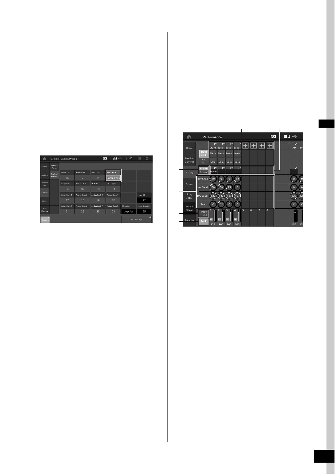
MODX+ Owner’s Manual
33
Playing the Keyboard
Mixing
Each Mixing can contain up to 16 Parts and a separate
Mixing can be created for each Part. You can adjust the
various mixing related parameters for each Part: volume,
pan, etc.
Basic procedure for Mixing
1 Touch the [Mixing] tab on the left side of the
Performance Play display.
The Mixing display appears.
1 Main category for each Part
2 Switching displays between 3-band EQ / 2-band EQ
3 EQ setting for each Part
4 Parameter values for each Part
5 Changing the display for Parts 1–16
6 Changing the display for the audio Parts (Parts 9–16
are not displayed)
2 Press the [PART SELECT MUTE/SOLO]
button
[1]–[16] buttons to select the
desired Part for which you want to adjust the
parameter values.
NOTE
By touching [Audio] (6) on the screen, the audio Part are
shown. You can set the parameters relating to the audio data
(AD Part) input from the A/D INPUT [L/MONO]/[R] jacks and the
audio data (Digital Part)* input from the [USB TO HOST]
terminal.
*The audio data which is set as “Digital L/R” among device ports
3 Move the cursor to the parameters for each
Part and change the parameter values by
turning the Data dial.
NOTE
• For more detailed parameter settings, press the [EDIT] button
in the Mixing display to open the Edit display.
• For details about the Mixing parameters and Mixing Edit, see
the Reference Manual PDF document.
Controlling the Super Knob by using a foot
controller
You can control the Super Knob by using a foot
controller (FC7).
1 Connect the foot controller (FC7) to the
FOOT CONTROLLER [1]/[2] jack.
2 Move the cursor to the Performance
name on the Performance Play display
and then press the [EDIT] button.
3 Touch the [Control] tab in the left of the
screen
[Control Number] tab.
4 Set “Foot Ctrl 1” or “Foot Ctrl 2” to
“Super Knob”—depending on which jack
you connected the foot controller (FC7).
1
4
2
5
6
3
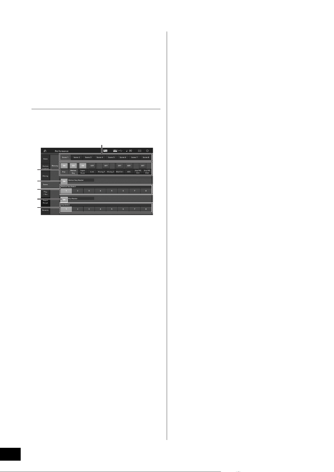
MODX+ Owner’s Manual
34
Playing the Keyboard
Using the Scene function
You can store all parameter settings such as Arpeggio type,
Motion Sequencer type, and the Part parameter values
together as a “Scene.” There are eight Scenes and you can
select them by pressing the [SCENE] button.
This is useful for simultaneously and drastically changing the
Arpeggio type and the Motion Sequencer type while you are
playing a single Performance.
Changing Scene settings
1 Touch the [Scene] tab on the left side of the
Performance Play display.
The Scene display appears.
1 Switching among Scenes 1–8
2 Turning functions for each Scene on/off
3 Turning the Motion Sequencer for All Parts on/off
4 Motion Sequencer type of the currently selected
Scene
5 Turning the Arpeggio for all Parts on/off
6 Arpeggio type of the currently selected Scene
NOTE
Sections 3 to 6 (see illustration above) are displayed only when
“Arp” and “Motion Seq” are selected in section 2.
2 Set Scenes 1–8 as desired.
When [Memory] is turned on for the function, the Motion
Sequencer type, or the Arpeggio type, the
corresponding function information is automatically
memorized to the currently selected [SCENE] button. By
pressing one of the SCENE [1]–[8] buttons, the Scenes
1–8 are switched and stored information for each Scene
is restored.
NOTE
You can also change Scene Settings from other setting displays.
After changing the parameters from other setting displays using
Knobs or Control Sliders to which you have previously assigned
parameters from the Scene Settings display, press one of the
SCENE [1]–[8] buttons while holding down the [SHIFT] button to
store the settings.
3 Store the Performance as necessary
(page 37).
NOTICE
If you select a different Performance or turn off the power
without storing your edited Performance, all the edits
you’ve made for the Scene will be erased.
1
2
4
3
6
5
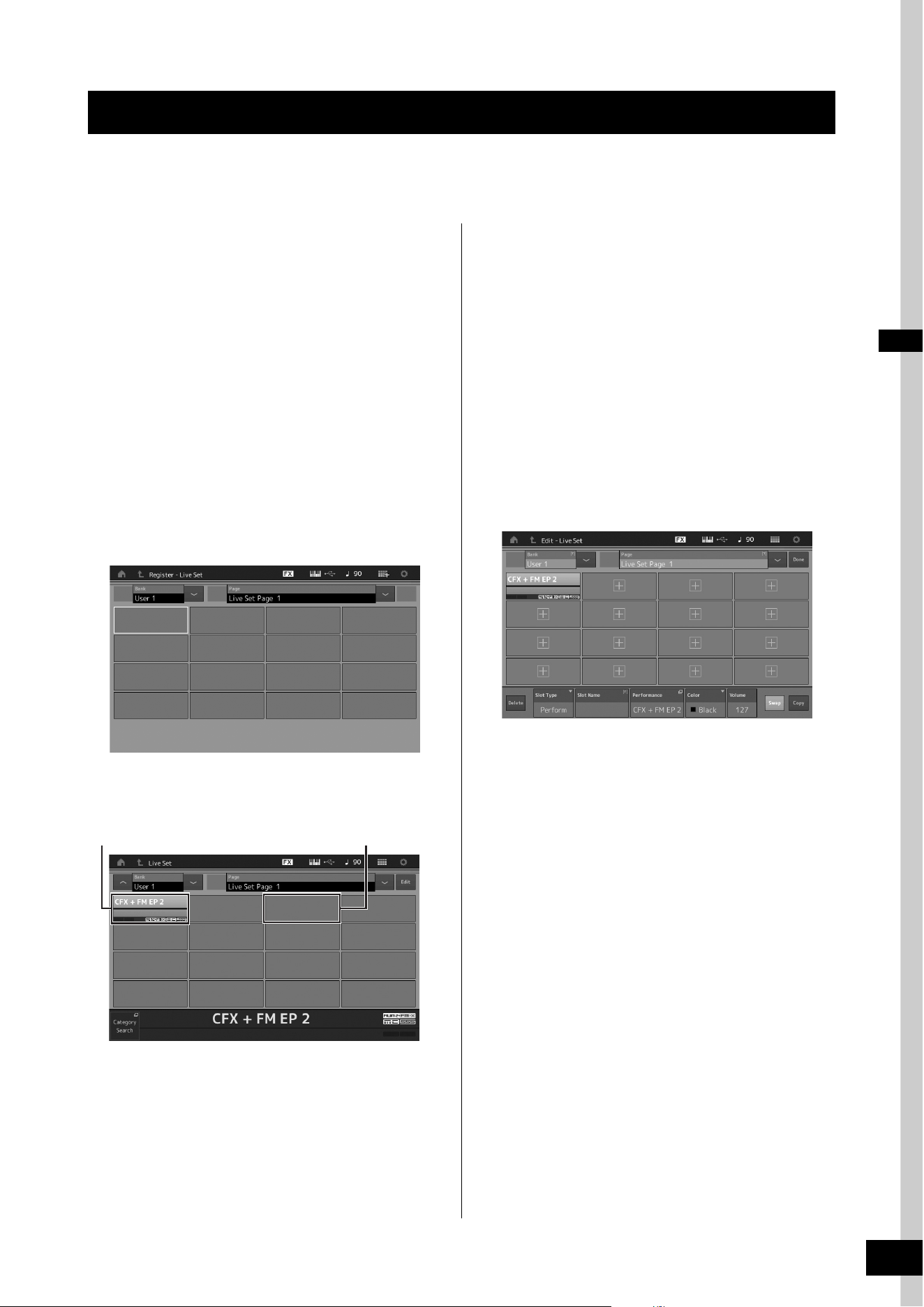
MODX+ Owner’s Manual
35
The Live Set is ideal for live performance situations since it lets you instantly switch among desired Performances. You can
create your own Live Set by simply grouping together your favorite Performances.
Registering a Performance to a
Live Set
Follow the instructions below to store Performances to Live
Sets.
NOTICE
• Before storing the currently editing Performance to the
Live Set, store the Performance itself (page 37).
• If you select a different Performance or turn off the power
without storing your edited Performance, all the edits
you’ve made will be erased.
1 Select the Performance you want to use.
2 Hold down the [SHIFT] button and press the
[LIVE SET] button.
The Live Set display appears.
Live Set display
3 Touch one of the slots. The currently selected
Performance will be registered in the slot.
Sorting registered Performances
in a Live Set
You can change the order of the Performances registered to
a Live Set on the Live Set Edit display.
1 Press the [EDIT] button while the Live Set
display is shown.
The Live Set Edit display appears.
(The Live Set Edit display will not be shown if a Live Set
of the preset bank/library bank is open.)
2 Select the slot containing the Performance
you want to move and touch [Swap] on the
screen.
The [Swap] lights up and now the slot can be changed.
3 Select the desired destination slot.
The original slot and the destination slot are switched
with each other.
Creating Your Own Live Sets
The performance registered in the slot
An empty slot
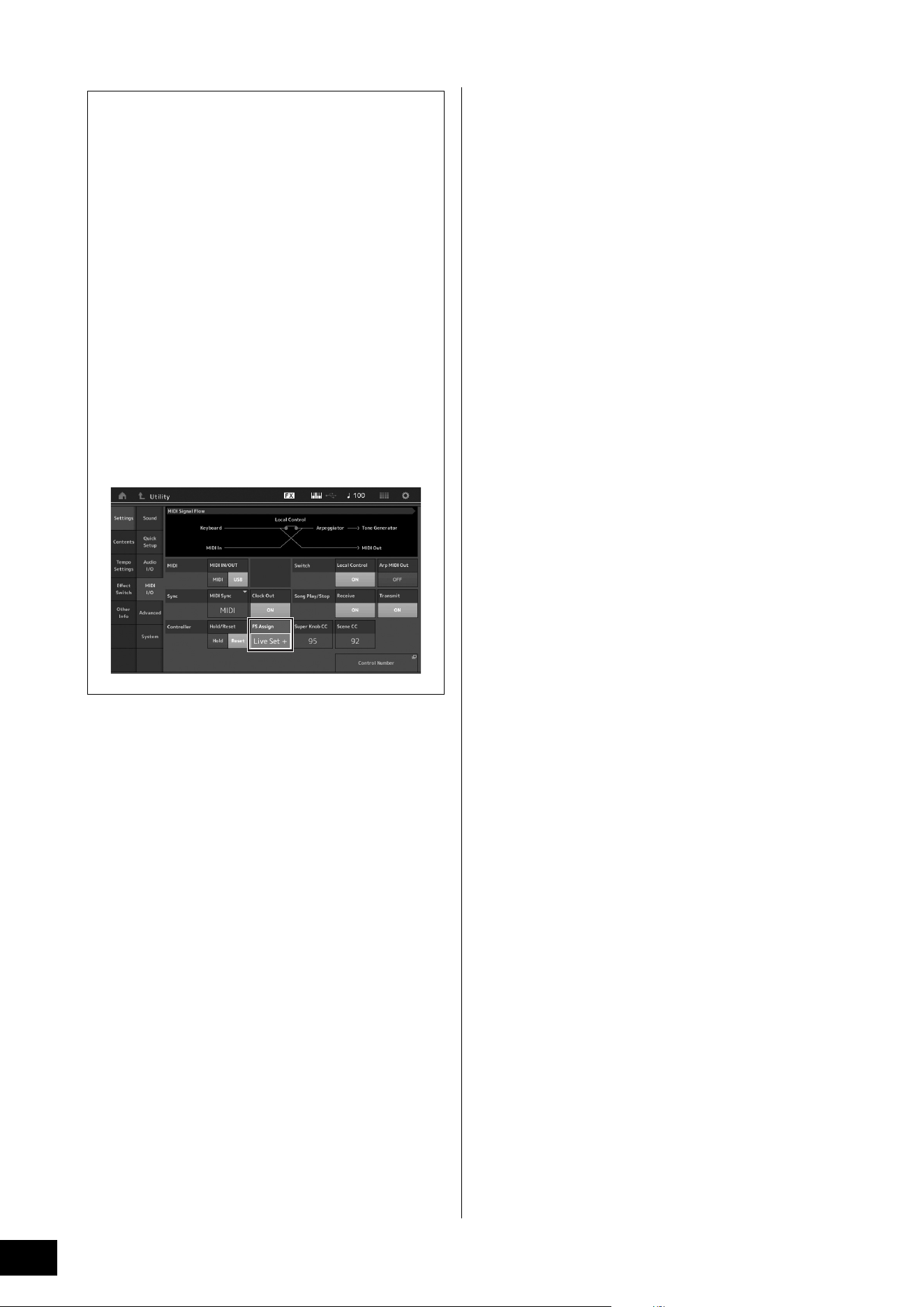
MODX+ Owner’s Manual
36
Creating Your Own Live Sets
Switching Performances stored in a Live Set
by using the footswitch
You can switch the Performances by using a
connected footswitch (FC4 or FC5). The setting for this
operation is as follows.
1 Connect the footswitch (FC4 or FC5) to
the FOOT SWITCH [ASSIGNABLE] jack.
2 Press the [UTILITY] button to call up the
Utility display, and then touch [Settings]
tab
[MIDI I/O] tab at the left side of the
screen.
3 Set “FS Assign” to “Live Set +” or “Live
Set -.”
When “Live Set +” is selected, the Performances
are switched in forward order. When “Live Set -” is
selected, the Performances are switched in reverse
order.
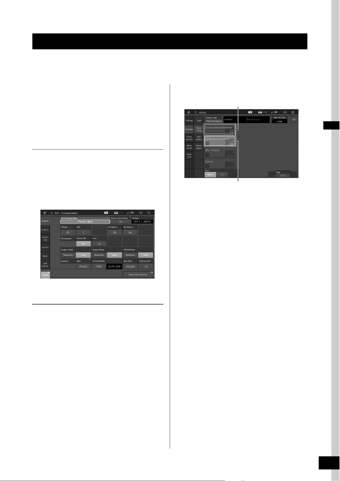
MODX+ Owner’s Manual
37
This instrument has various edit displays for Parts, Performances, effects, and Arpeggios. This chapter explains how to create
an original Performance by combining multiple Parts.
Performance Editing
“Performance Editing” refers to the process of creating a
Performance by changing the parameters that make up the
Performance. This can be done in the Performance Edit
display.
Basic operations for editing a
Performance
1 Move the cursor to the Performance name on
the Performance Play display, then press the
[EDIT] button.
2 Touch the [General] tab at the left side of the
screen to edit the Performance.
Performance Edit display
Storing the Performance (Store)
After editing, store the Performance to internal memory.
Press the [STORE] button to store the Performance.
NOTICE
• The edited Performance will be lost when selecting a different
Performance or turning the power off.
• If you overwrite a Performance in the User bank, it will be per-
manently deleted. When you store the edited Performance, be
careful not to overwrite any important User Performances.
Important data should always be saved to a USB flash drive
connected to the [USB TO DEVICE] terminal. For detailed
instructions on saving, see page 60.
NOTE
You can select any desired Part by using the [PART SELECT MUTE/
SOLO] buttons during editing of the Performances, and edit the
selected Part.
1 Press the [STORE] button to call up the Store
display.
2 Set the destination for storing the
Performance.
To store the newly edited Performance, touch “+” in the
[Store As New Performance] section.
NOTE
To overwrite the previously stored Performance, touch [Overwrite
Current Perf.] or the Performance to be overwritten.
3 The Text Input display appears. Input the
name of the stored Performance.
For detailed instructions on inputting characters, see
“Naming (character inputting)” in “Basic Operation and
Displays” (page 21).
4 Select “Done” on the Text Input display to
actually execute the Store operation.
NOTE
If you are overwriting the previously stored file, a confirmation
display appears after Step 2. Select “YES” to execute the Store
operation.
Editing the Settings
Storing a new Performance
Performance previously stored
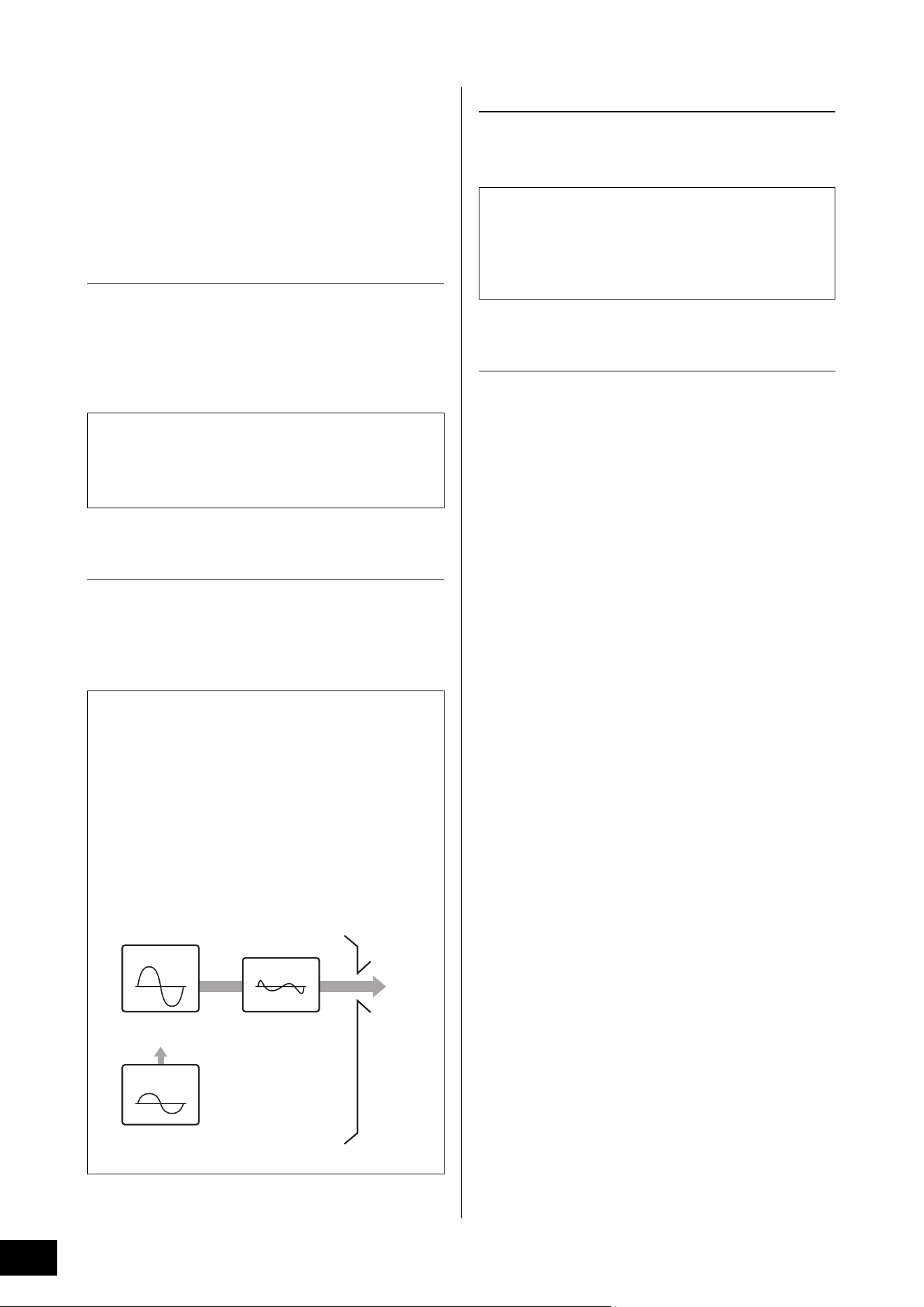
MODX+ Owner’s Manual
38
Editing the Settings
Part Editing
“Part Editing” refers to the process of creating a Part by
changing the parameters that make up the Part. This can be
done in the Element Common/Key Common/Operator
Common Edit display and the Element/Key/Operator Edit
display. The actual parameters that are available differ
depending on the Part type.
Normal Part (AWM2) Edit
A Normal Part (AWM2) (having pitched musical instrument
sounds) can consist of up to eight Elements. An Element is
the basic, smallest unit for a Part. There are two types of
Normal Part (AWM2) Edit displays: Element Common Edit
display, for editing settings common to all eight Elements;
and Element Edit display, for editing individual Elements.
Normal Part (FM-X) Edit
A Normal Part (FM-X) (assigned FM-X sounds) can consist of
up to eight Operators. There are two types of Normal Part
(FM-X) Edit displays: Operator Common Edit display, for
editing settings common to all eight Operators; and Operator
Edit display, for editing individual Operators.
Drum Part Edit
There are two types of Drum Part Edit displays: Key
Common Edit display, for editing the settings that apply to all
Drum keys; and Key Edit display, for editing individual keys.
Basic operation of Part Edit
1 Move the cursor to the Part you want to edit
in the Performance Play display, then press
the [EDIT] button.
You can also use [PART SELECT MUTE/SOLO] button to
select a Part.
2 Touch the [Part Settings] tab at the left side of
the screen
[General] tab to edit the desired
Part.
For Normal Parts (AWM2)
For Element Common Editing, touch the Element
[Common] tab.
For Element Editing, press the corresponding Number
button of the element to be edited from among the
[Elem1]-[Elem8] tabs.
For Drum Parts
For Key Common Editing, touch the Drum Key
[Common] tab.
For Key Editing, press the tab corresponding to the Drum
Part you want to edit (BD, SD, etc.).
You can switch the Keys of each instrument sound
(assigned to C1 to C#2) by using the [BD]–[Crash] tabs.
For selecting Keys other than the Keys assigned to C1 to
C#2, turn on “Keyboard Select” on the display and play
the note assigned the Key to be edited.
For Normal Parts (FM-X)
For Operator Common Editing, touch the Operator
[Common] tab.
For Operator Editing, press the corresponding Number
button of the operator to be edited from among the
[OP1]–[OP8] tabs.
NOTE
For details about the Part parameters, see the Reference Manual
PDF document.
An Element is created by applying various parameters
(Effect, EG, etc.) to the waveform of the instrument sound.
A Normal Part of this instrument (AWM2) consists of up to
eight Elements.
The abbreviation “FM” of FM-X stands for “frequency
modulation,” which is special tone generation system that
uses one waveform’s frequency to modulate another
waveform, to produce a completely new one. Waveforms
are generated by “operators,” of which the MODX+ has
eight. An operator that generates a fundamental waveform
is a “carrier,” and an operator that modulates these
waveforms is a “modulator.” Each of the eight operators
can be used as either a carrier or a modulator. By
changing the way operators are combined and controlling
the modulation with other parameters such as levels and
envelopes, you can create richly textured sounds that
change in a highly complex fashion.
Carrier
Waveform to be
modulated
Sound output
Modulator
Modulated
waveform
Modulating
waveform
When the volume of the
modulator increases, the
carrier waveform changes.
* The carrier waveform is not
affected when the volume
is 0.
Drum Parts are mainly percussion/drum sounds that are
assigned to individual Keys. You can create various drum
Parts by changing assigned sound types and adjusting the
pitch and EQ.
Drum Parts of this instrument consist of up to 73 Keys.
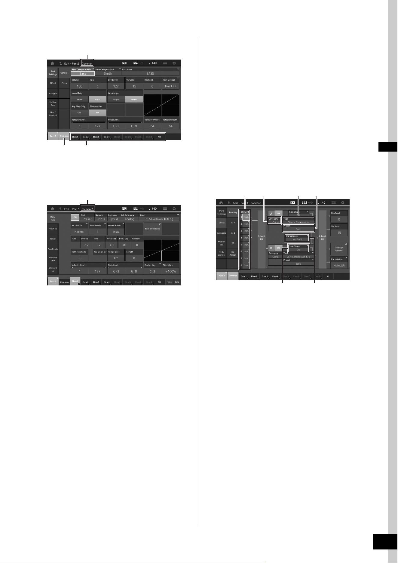
MODX+ Owner’s Manual
39
Editing the Settings
Element Common Edit display
The structure of the display is the same as for the Key/
Operator Common Edit display.
Element Edit display
The structure of the display is the same as for the Key/
Operator Edit display.
3 Store the Performance as necessary.
Part Effect Editing
This instrument features a wide variety of Effects, letting you
add Variation and Reverb processing to the selected Part for
your keyboard performance. Simply changing the Effect
type applied to the preset Part lets you instantly come up
with different sounds. The instructions below explain how to
set the Effect type and the related parameters applied to the
Part, and then store the settings as a User Performance.
1 Move the cursor to the Part to be edited on
the Performance Play display, and then press
the [EDIT] button.
2 Touch the Element [Common] button.
3 Touch the [Effect] tab in the left of the screen
[Routing] tab.
The Effect display for Element Common Edit appears.
1 Output of each Element/Key
2 Category of Insertion Effect A
3 Type of Insertion Effect A
4 Preset of Insertion Effect A
5 Connection method between Insertion Effects A and
B
6 Selection of Side Chain/Modulator
4 Set the output of each Element/Key (1).
5 Select the parameters (Effect category (2),
Effect type (
3), and Effect preset (4))
corresponding to Insertion Effect A.
6 Set the connection method between Insertion
Effects A and B (
5).
7 Set the Side Chain/Modulator of Insertion
Effect B (
6).
NOTE
The Side Chain/Modulator uses the output from one track to
control an effect in a different track. You can specify the Effect
type for activating the feature so that input signals for Parts other
than the selected Part or the audio input signal can control the
specified Effect.
This trigger is called “Side Chain” or “Modulator” depending on
the Effect Type.
Indicates that the Element Common Edit display is active.
Switches between Element Common Edit and Element Edit.
Indicates that the Element Edit display is active.
2
31
5
4
6
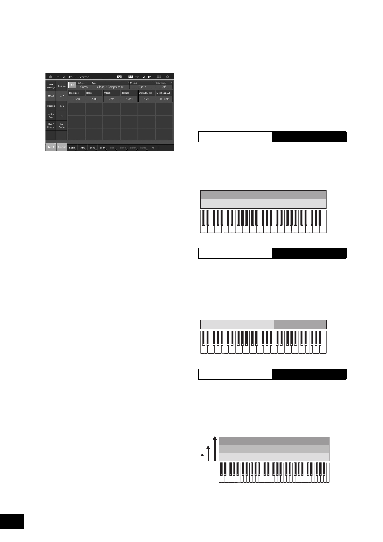
MODX+ Owner’s Manual
40
Editing the Settings
8 Touch the [Ins A] tab at the left side of the
screen.
The display for editing effect parameters selected in
Step 4 appears.
9 Set the parameters as necessary.
Try narrowing in on your desired sound by finely editing
the parameters provided for each Effect Type.
10 Edit Insertion Effect B by using the same
operation.
11 Store the Performance as necessary.
How Parts are assigned to a
Performance
By default (when shipped from the factory), various types of
Performances are provided in the Preset Banks. For some of
these Performances, it may not be immediately obvious how
to play them or use them, since they are quite complicated.
In this section, you’ll learn the typical ways in which
Performances are created, and thus better understand how
to play and use them. This section covers the typical four
Part assignments.
This method lets you play multiple (two or more) Parts
simultaneously by pressing any notes.
For example, you can create a thicker sound by combining
two similar Parts—for example, two different Strings Parts,
each with a different attack speed.
This method lets you play different Parts with your left hand
and right hand. By assigning a Strings Part to the lower
range and assigning a Flute to the higher range separately
as illustrated below, you can play Strings accompaniment
with your left hand and while playing Flute melody with your
right hand.
This method lets you trigger different Parts depending on
your playing strength (velocity). In this example below,
playing notes at low velocities triggers Strings sounds with a
slow attack speed. Playing notes at middle velocities
triggers Strings sounds with a fast attack speed. Playing
notes at high velocities triggers Orchestra Hits.
Compare function
The Compare function lets you switch between the just-
edited sound and its original, unedited condition, allowing
you to hear how your edits affect the sound.
Press the [EDIT] button while the Edit display is shown, so
that the [EDIT] button flashes. In this status, the sound
settings prior to editing will temporarily be reinstated for
comparison purposes. Press the [EDIT] button again to
return to the original status.
Performance Structure Layer
Performance Structure Split by Note range
Performance Structure
Split by Velocity range
C1 C2 C3 C4 C5 C6
Strings having a fast attack speed
Strings having a slow attack speed
Part 2
Part 1
C1 C2 C3 C4 C5 C6
Part 2Part 1
Strings
Flute
C1 C2 C3 C4 C5 C6
Orchestra Hit
Strings having fast attack speed
Strings having slow attack speed
Part 3
Part 2
Part 1
Velocit y
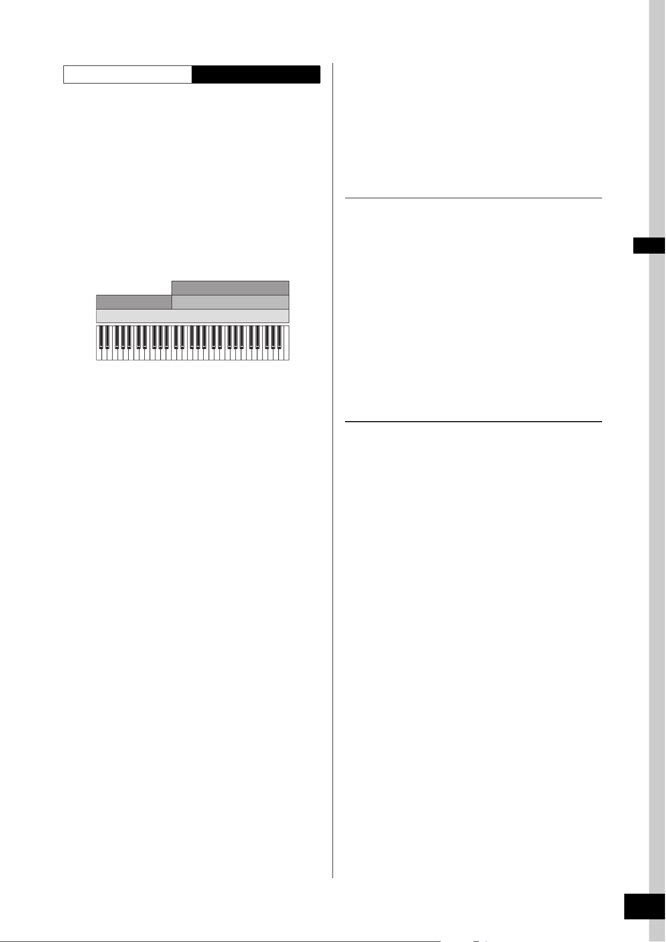
MODX+ Owner’s Manual
41
Editing the Settings
With this method, you can play all the parts of a band by
yourself. With the MODX+, you can assign different
Arpeggio types to each of the eight Parts in a Performance.
For example, you could assign four different Arpeggio types
to four Parts, as shown below, so that Bass Arpeggios are
played on the lower range of the keyboard, Guitar and Piano
Arpeggios on the upper range, and Drum Arpeggios on all
ranges of the keyboard. Then, by simply playing the
appropriate ranges of the keyboard, you can add full,
dynamic accompaniment to your performance.
In addition, you can change the Arpeggio Type assignment
from [Motion Control]
[Arpeggio] on the display, allowing
you to set different Arpeggio Types for the intro, verse,
chorus, and ending of your song.
Using or combining the four methods described above gives
you the ability to create a rich variety of Performances. By
default, many Performances stored in the Preset Banks have
been created via the above methods. Try out various
Performances and see which method is used for each.
Creating a Performance by
combining Parts
After checking out the pre-programmed Performances in the
Preset Banks, try creating your own original Performance. In
this section, we’ll create a Performance by combining two
Parts.
Selecting a Performance
For demonstration purposes, we’ll assign a piano sound to
Part 1.
1 Move the cursor to the Part name of the Part 1
on the Performance Play display and press
the [CATEGORY] button while holding down
the [SHIFT] button.
The Part Category Search display appears.
2 Select [Full Concert Grand] from the
Performance list.
3 Press the [EXIT] button.
Playing several Parts together (Layer)
Try combining two Parts by assigning a favorite Part to
Part 2.
1 Move the cursor to the Part name of the Part 2
on the Performance Play display and select
the desired sound by pressing the
[CATEGORY] button while holding down the
[SHIFT] button.
2 Play the keyboard.
The Part 1 (Piano) and Part 2 (the sound you have
selected above) are sounded simultaneously in a layer.
3 Press the [EXIT] button.
Next, let’s play different Parts with the left and right hands.
Performance Structure Using Arpeggios
C1 C2 C3 C4 C5 C6
Part 3
Part 4
Part 1
Guitar with Arpeggio
Piano with Arpeggio
Bass with Arpeggio
Drums with Arpeggio Hold set to ON
Part 2
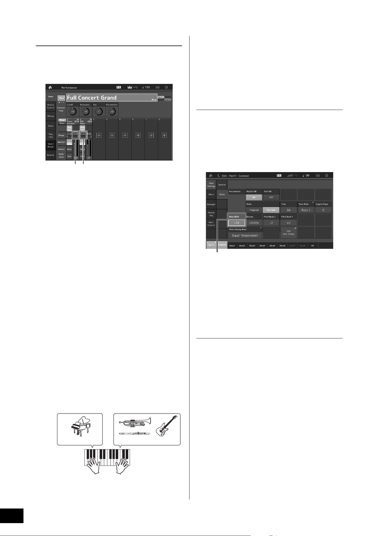
MODX+ Owner’s Manual
42
Editing the Settings
Split
You can play different Parts with the left and right hands by
assigning one Part to Part 1, with a note range in the lower
section of the keyboard, and a different Part to Part 2, with a
note range in the higher section of the keyboard.
1 Note Limit Low (the lowest note of the range for the Part)
2 Note Limit High (the highest note of the range for the
Part)
1 Touch the Note Limit High (2) of Part 1 or
move the cursor to
2 and press the [ENTER]
button.
2 Touch the [Keyboard] menu at the left side of
the screen to turn it on.
3 Set the highest note of Part 1 by pressing the
corresponding key.
The note number in the Range section of Part 1 changes.
4 Touch the Note Limit Low (1) of Part 2 or
move the cursor to
1 and press the [ENTER]
button.
5 Set the lowest note of Part 2 by pressing the
corresponding key.
The note number in the Range section of Part 2 changes.
6 Touch the [Keyboard] menu at the left side of
the screen to turn it off.
7 Play the keyboard.
The notes you play with your left hand sound the Piano
Part (Part 1), while the notes you play with your right
hand sound the different Part (Part 2) you have selected.
8 Press the Slider Function [PART]/[ELEMENT/
OPERATOR] button to select “PART.”
9 Use the Control Sliders 1 and 2 to adjust the
volume for Parts 1 and 2.
Changing the note range of the split Part
to one octave lower
Change the note range of Part 2 to one octave lower.
1 Move the cursor to Part 2 and press the
[EDIT] button for Part edit.
2 Touch the [Part setting] tab at the left side of
the screen
[Pitch] tab.
3 Select “Note Shift” to adjust the Pitch.
The pitch is shifted in semitone steps. Set “-12” to make
the note range one octave lower.
4 Play the keyboard.
Changing the Arpeggio settings for each
Part
Try changing the Arpeggio settings for each Part. You can
assign the rhythm or backing pattern that best matches the
desired style of music to the Performance.
1 Move the cursor to Part 1 and press the
[EDIT] button to call up the Element Common
Edit display.
2 Touch the [Arpeggio] tab at the left side of the
screen
[Common] tab (near the top of the
display).
The display for setting common Arpeggio parameters for
all Arpeggio type appears.
Note that the Arpeggio Hold parameter is useful as well
as the Arpeggio type selection. When this parameter is
set to “on,” the Arpeggio playback continues even if the
note is released. This parameter should be set to “on”
when a Drum sound is assigned to the Part and you wish
to have playback of the Arpeggio (rhythm pattern)
continue regardless of whether you hold the note or not.
12
Part 1: Piano Part Part 2: Other Part
Note Shift
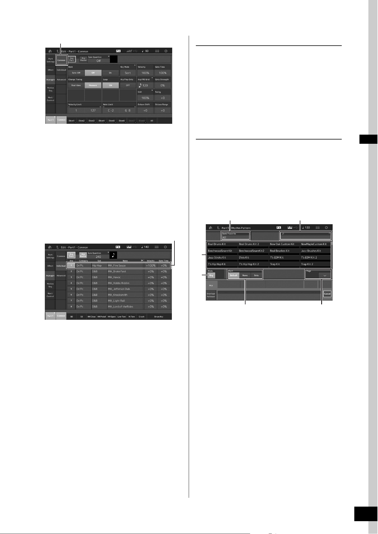
MODX+ Owner’s Manual
43
Editing the Settings
3 Touch the [Individual] tab to call up the
setting display for each Arpeggio Type.
4 Touch the Arpeggio type and select the
[Category Search] menu at the left side of the
screen. (Alternately, you can press the
[CATEGORY] button.)
The Category determines the instrument type and the
Sub Category determines the music type.
The Arpeggio types include variations for each section of
the song, such as intro, verse, refrain, chorus, and
bridge. Play the keyboard to hear the arpeggios to select
one you like.
Go on and assign other Arpeggio types in the same way
as desired.
5 Store the Performance as necessary.
Using the Rhythm Patterns
The [Rhythm Pattern] button provides a simple way to add a
rhythm part to the current Performance.
By combining rhythm patterns and the Envelope Follower,
you can modify the patterns even further.
Here, as an example, we explain how to add the rhythm
pattern “8Z Trance Basics 1” to the Performance
“Supertrance,” and then modify the sound with the Envelope
Follower.
Adding a Rhythm Part (simple way)
1 Select the desired Performance for adding
the rhythm part.
Here, select “Supertrance.”
2 Press the [RHYTHM PATTERN] button.
The Rhythm Pattern display appears.
When all of the parts in Part 1 to 8 are already in use, the
message “Part Full” appears and the rhythm pattern
cannot be added.
1 Bank/Favorite
2 Name Search
3 Kit Selection
4 Mute
5 Sort
6 Switching pages
3 From the Rhythm Pattern List, touch the
Rhythm Pattern kit you want to use.
Here, touch “8Z Trans Basics1.”
A rhythm part is added.
4 Play the keyboard and the rhythm pattern
starts playing.
[Common] tab
Setting of Arpeggio type
3
4
1 2
5 6
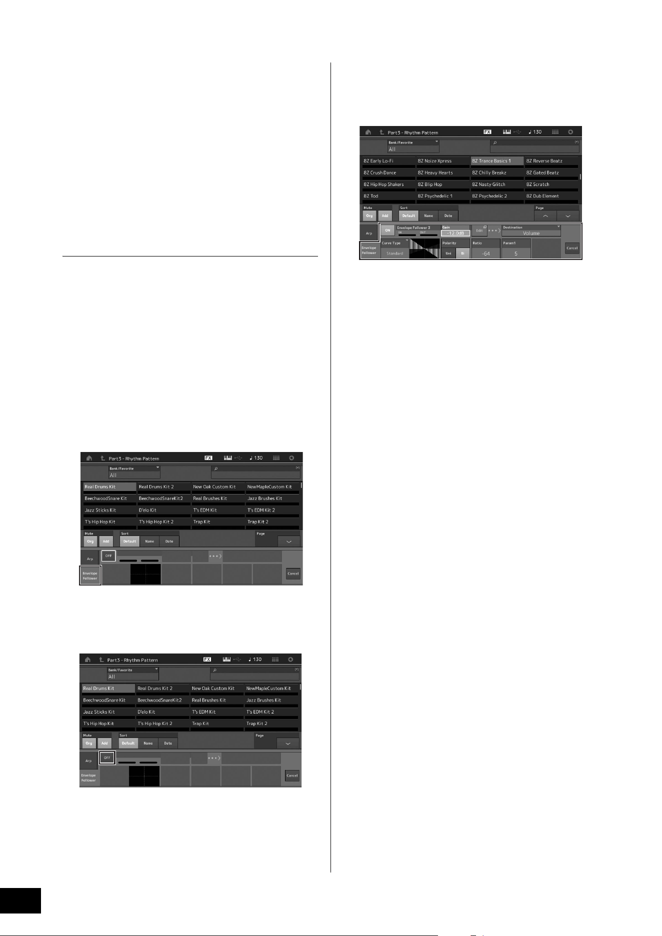
MODX+ Owner’s Manual
44
Editing the Settings
5 Press the [PERFORMANCE (HOME)] button
or [EXIT] button to set the Rhythm Pattern.
The Rhythm Pattern display closes.
NOTE
You can also touch the HOME icon to confirm the selection.
6 To stop the rhythm pattern, press the [ARP
ON/OFF] button or the [J] (Stop) button.
NOTE
You can also stop the rhythm pattern by touching the [Arp Hold
On] button on the display.
Setting the Envelope Follower
Envelope Follower is a feature that extracts the envelope (or
amplitude envelope) of a waveform from the input signals,
and then lets you use that envelope as a controller for
modifying sounds. For example, by assigning a rhythm
pattern to a Part and setting the Envelope Follower of the
Part as a “Source,” the sound of other Parts are modified
accordingly. This is especially useful for automatic
“ducking,” where you want to lower the volume of other
instruments while a certain instrument sound is being
played.
1 Touch the [Envelope Follower] tab at the
bottom of the Rhythm Pattern display.
The Envelope Follower display appears.
2 Turn the Envelope Follower switch “ON.”
Here, you can play the keyboard to hear the sound with
the Envelope Follower enabled.
3 Adjust settings as needed.
Here, in this example, set the Curve Polarity (Polarity) to
“Bi,” the Curve Ratio (Ratio) to “-63,” and the Gain (Gain)
to “-12dB.”
For setting other parameters, touch the [EDIT] button on
the screen, and open the Envelope Follower Setting
display.
When you want to change the Rhythm Pattern kit or the
Arpeggio Type, press the [RHYTHM PATTERN] button to go
back to the Rhythm Pattern display. The Envelope Follower
settings are retained even after the new kit or the Arpeggio
type is selected.
MODX+ Owner’s Manual
45
You can record your performance on the MODX+ as MIDI data (Songs or Patterns) to the internal storage, or as audio data to a
USB flash memory plugged into the instrument.
Terminology
Song
A Song on this instrument is effectively the same as a song
on a MIDI sequencer, and playback automatically stops at
the end of the recorded data. The MODX+ can store up to
128 Songs.
Track
This is a memory location on the sequencer where your
musical performances (made up of MIDI events) are stored.
The MODX+ provides 16 tracks, which correspond to the 16
Mixing Parts.
Realtime Recording
The instrument records the performance data as it is played
along with a metronome. Realtime Recording features three
available methods: Replace, Overdub and Punch In/Out.
• Replace lets you overwrite an already recorded Track with
new data, erasing the previously recorded data.
• Overdub lets you add more data to a Track that already
contains data—in other words, recording new notes on top
of the previous ones.
• Punch In/Out lets you re-record selectively over a specific
area of the Track.
Pattern
A Pattern is a set of sequences for repeating the same
performance on each Scene (such as intro, verse, bridge,
and ending). By recording the performances of each Scene
and then combining them, you can efficiently create songs,
and play them flexibly during live performances.
For MODX+, you can record up to 8 Scenes with 16 tracks
per Pattern, and you can save up to 128 Patterns.
MIDI (Song) Recording
This instrument features two sequencer types (Song and
Pattern) for recording your keyboard performance as MIDI
data. This function allows you to instantly store phrases that
you improvise, create and perform. You can create full,
complex multi-instrument arrangements and complete
songs, using DAW software.
The Song sequencer lets you record an entire song, and the
Pattern sequencer lets you create entire songs by combining
the individual ‘building-block’ performances recorded for
each Scene.
This section explains how to record a Song using the Song
sequencer. For more information on Pattern recording and
Pattern sequencers, please refer to the Reference Manual.
Recording to a track
In this section, you’ll learn how to record your keyboard
performance, by recording a part to Track 1. However, you’ll
first need to set up the MODX+ for recording.
1 Touch the [Play/Rec] tab in the left of the
Performance Play display.
The recording display appears.
2 Touch the [MIDI] tab in the left of the screen.
3 Press the [I] (Record) button.
The Record Setup display appears.
NOTE
Alternately, you can simply press the [I] (Record) button in the
Performance display, to perform Steps 1–3 at once.
1 Song name
2 Currently selected Performance name
3 Time Signature (Meter)
4 Position (starting position of Recording/Playback)
5 Quantize
6 Position corresponding to the entire sequence
7 Recorded time of the entire sequence
8 Playback on/off for each track
9 Shortcut to the Tempo Settings display
) Changing the tempo
Recording and Playback
1
3
4
)
7
9
5
6
8
2
MODX+ Owner’s Manual
46
Recording and Playback
4 Set the following parameters on the Record
Setup display.
4-1
Move the cursor to Time Signature (Meter) (3), and
then set the value. For this example, set this to “4/4.”
4-2 Set Quantize to “240 (8th note)” in Record Quantize
(5). This convenient feature lets you automatically
quantize (or “clean up” the timing of) the notes in real
time, as you record. Quantize aligns the timing of note
events to the nearest beat. Normally, the smallest note
value in the notation (if you're playing from sheet music)
should be set.
5 After completing recording setup, press the
[R] (Play) button to start recording.
Press the [R] (Play) button, then actually start recording
after the count-in.
6 When you’ve finished playing, press the
[J] (Stop) button to stop recording.
If you’ve played any wrong notes, press the [J] (Stop)
button, then try recording again.
Recording with the click
Follow the steps below to use the click during MIDI
recording.
1 Press the [UTILITY] button and touch [Tempo
Settings] (or Touch the [Click Settings] button
where available) on the screen to call up the
Tempo settings display. Set the Click “Mode”
to “Rec.”
NOTE
When “Rec/Play” is set, the click sounds during MIDI recording
and playback. When “Always” is set, the click will always
sound.
Re-recording a specific part of a Song
(Punch In/Out)
Use the Punch In/Out recording method to record over only
a specific portion of the Track. If you set the start point
(Punch In) and end point (Punch Out), and then start
recording from the top of the Song, the actual recording
will be done only between the Punch In and Punch Out
points. In the eight-measure example below, only the third
through the fifth measures are re-recorded.
NOTE
Note that the Punch In/Out method always replaces (destroys)
the original data over the specified area.
To execute Punch In/Punch Out recording in the above
condition, set the following parameters beforehand on the
Record Setup display.
1 “Record Type”: “punch”
2 Punch In: 003:01
Playback of the recording Track is turned off from this
point, and your keyboard performance will be
recorded to the Track.
3 Punch Out: 006:01
Recording ends at this point and normal playback of
the recording Track starts.
1234567 8
1234567 8
Before re-recording
Recording start Recording stop
Punch In point
Punch Out point
After re-recording
Newly recorded data
231
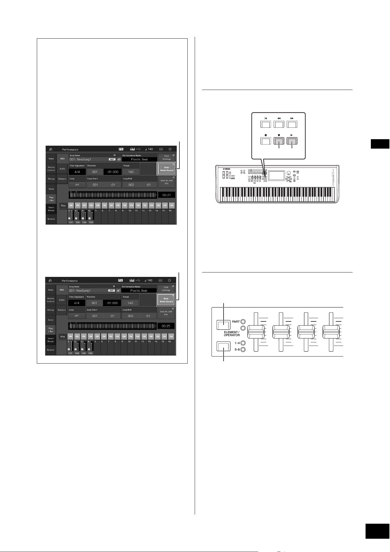
MODX+ Owner’s Manual
47
Recording and Playback
Playing a Song
In this section, you’ll learn how to use convenient mute/solo
functions while playing back a recorded song.
Song playback
1 Press the [R] (Play) button to start the Song.
NOTE
To adjust the volume level of the Songs, use the [MASTER
VOLUME] knob.
2 Press the [J] (Stop) button to stop the Song.
Adjusting the volume of each Part
You can adjust the volume for each of four Parts, using the
Control Sliders.
You can change the volume for Parts 5–8 by first pressing
the [PART]/[ELEMENT/OPERATOR] button to select PART,
and then pressing the Slider Select [1–4] [5–8] button.
In addition to sliders, the Knobs 1–4 (5–8) can be used to
affect the Part setting of the Song playback in real time. For
details, refer to the Reference Manual PDF document.
Cancelling your most recent recording
(Undo/Redo)
The Undo Job cancels the changes you made in your most
recent recording session and restores the data to its
previous state. Redo is available only after using Undo,
and lets you restore the changes you made before undoing
them.
1 Undo (This display is not available if nothing has been
recorded.)
When [Undo] is touched, the display prompts you for
confirmation. Selecting Undo cancels the previous
recording.
2 Redo (This display is not available if Undo has not
been operated.)
When [Redo] is touched, the display prompts you for
confirmation. Selecting Redo restores the change you
made.
1
2
Stop Play
[PART]/[ELEMENT/OPERATOR] button
Slider Select [1–4] [5–8] buttons
MODX+ Owner’s Manual
48
Recording and Playback
Recording your performance as
audio
Your performances on the MODX+ can be recorded as WAV
format (44.1-kHz, 24-bit, stereo) audio files to a USB flash
drive. The recording level is fixed, and it is possible to record
continuously for up to 74 minutes (assuming that the USB
storage device has sufficient free memory).
NOTICE
The MODX+ should never be turned off during recording,
playback, or while the recorded audio file is being saved.
Turning off the MODX+ at that time may make it impossible
to subsequently access the USB flash drive.
1 Connect a USB flash drive to the [USB TO
DEVICE] terminal of the MODX+.
2 Touch the [Play/Rec] tab in the left of the
Performance Play display.
The recording display appears.
3 Touch the [Audio] tab in the left of the screen.
4 Press the [I] (Record) button to setup the
audio recording.
The Record Setup display appears.
1 Play position
2 Current play position in the entire audio data
3 Available recording time
4 Level meter
5 Trigger level
5 Set the required trigger level (5).
If you set the trigger level to “manual,” recording will
begin whenever you press the [R] (Play) button.
Alternatively, if you set a value between 1 and 127,
recording will begin automatically whenever the
playback volume exceeds that level. The level set here
will be indicated by blue triangles in the level meter (4).
For best results, set this parameter as low as possible to
capture the entire signal, but not so low as to record
unwanted noise.
6 Press the [R] (Play) button.
If you have set the trigger level to “manual,” recording
will begin immediately right after you press the [R] (Play)
button. While the recording, the [I] (Record) button will
light red and the [R] (Play) button will light green. If you
have set a value between 1 and 127 as the trigger level,
the recording will begin automatically whenever the
playback volume exceeds that level.
7 Play the keyboard.
If you set the trigger level to a value between 1 and 127,
recording will begin automatically whenever the
playback volume exceeds that level.
8 When you have finished playing, press the
[J] (Stop) button.
The recorded audio file will be saved on the selected
device.
Playing an audio file
As described below, the MODX+ can play audio files (.wav)
from a USB flash drive, regardless of whether they have
been created by the instrument itself or come from another
source.
1 Connect a USB flash drive to the [USB TO
DEVICE] terminal of the MODX+.
2 Touch the [Play/Rec] tab [Audio] tab at the
left side of the Performance display.
3 Touch “Audio Name” and then select [Load]
menu at the left side of the screen.
4 Select the source USB flash drive and folder.
5 Select the desired file (.wav) on the USB flash
drive to execute the Load operation.
1 Audio name
2 Audio volume
3 Audio length
6 Press the [R] (Play) button.
The audio file will begin playing.
7 Move the cursor to “Audio Volume” (2), and
then adjust the playback volume by using the
data dial.
8 Press the [J] (Stop) button to stop playback.
NOTE
Keep in mind that you can also play a selected Performance on
the keyboard during audio playback.
2
4
3
5
1
2
3
1
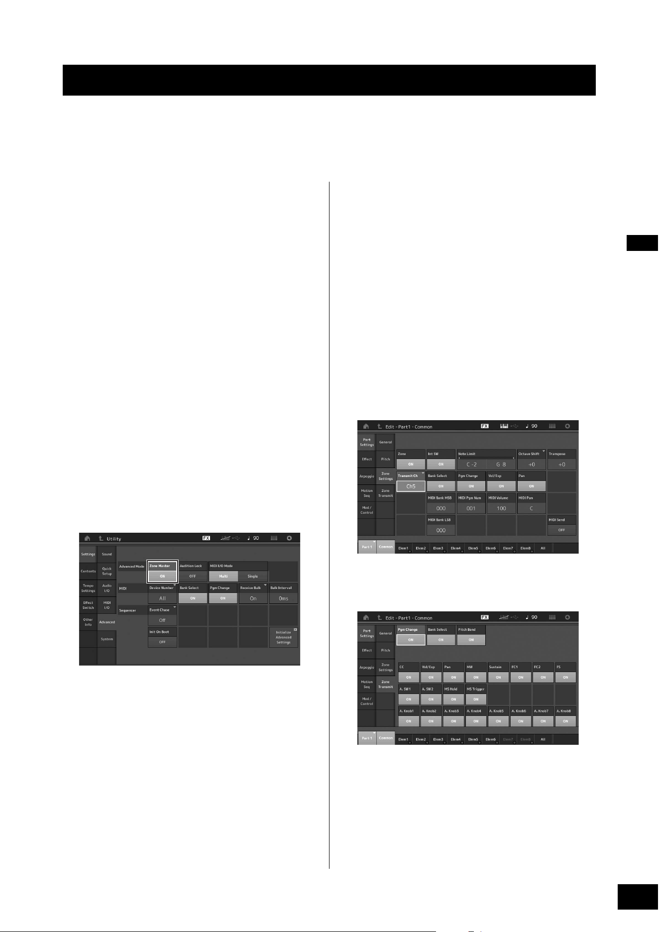
MODX+ Owner’s Manual
49
The Master Keyboard function lets you assign up to eight separate Zones in each Performance for use as a master keyboard
controller.
You can call up the settings for controlling an external MIDI device instantly anytime you need by combining with the Live Sets.
Accordingly, you can change and control the connected external MIDI tone generator in sequence while performing live.
Making settings for use as a
master keyboard—Zone
When you use the MODX+ as a master keyboard, you can
divide the keyboard into a maximum of eight independent
areas (called “Zones”). Different MIDI channels and different
functions of the Knobs and Control Sliders can be assigned
to each Zone. This makes it possible to control several Parts
of the internal multi-timbral tone generator simultaneously by
a single keyboard, or control Performances of an external
MIDI instrument over several different channels in addition to
the internal Performances of this synthesizer itself—letting
you use the MODX+ to effectively do the work of several
keyboards. You can set the parameters related to the eight
Zones and store the settings.
First, set the MODX+ as a master keyboard by activating the
Zone settings.
1 Press the [UTILITY] button to call up the
Utility display.
2 Touch the [Settings] tab [Advanced] tab at
the left side of the screen.
3 Touch [Zone Master] to turn it on.
4 Press the [EXIT] button.
This stores the setting and returns to the previous
display.
Next, make settings according to the Master Keyboard
(Zone) for each Performance.
1 Press the [PERFORMANCE (HOME)] button
to call up the Performance Play display.
2 Move the cursor to the desired Part of the
currently selected Performance and press the
[EDIT] button to edit the Part.
3 Touch the [Part Settings] tab [Zone
Settings] tab at the left side of the screen.
4 Touch [Zone] to turn it on.
5 Set the Zone related parameters such as MIDI
transmit channel and Note Limit.
6 Touch the [Zone Transmit] tab to set the
transmit switches as desired.
After completing these settings, press the [STORE] button to
store the Performances.
For details about Zone settings, see the Reference Manual
PDF document.
Using as a Master Keyboard
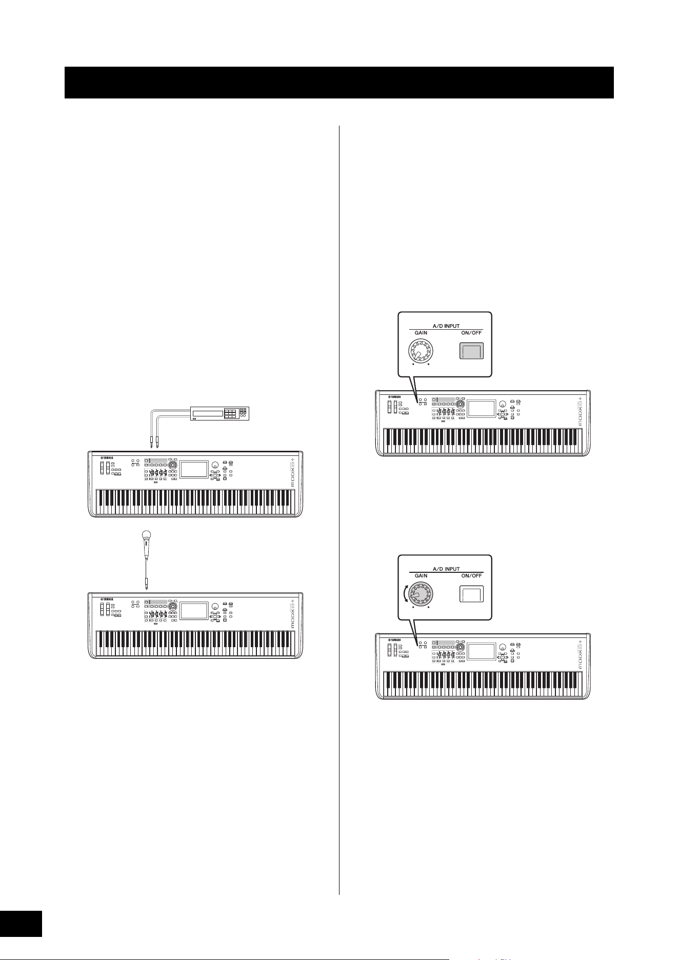
MODX+ Owner’s Manual
50
Playing the keyboard along with
the sound input from the A/D
INPUT [L/MONO]/[R] jacks
You can have the A/D input sound—such as your voice
through a microphone, a CD player, or a synthesizer—
assigned as an Audio Input Part. Various parameters such
as volume, pan, and effects can be set to this Part and the
sound is output together with the sound of your keyboard
performance.
1 Make sure to turn off the power of this
instrument and set the A/D INPUT [GAIN]
knob to the minimum.
2 Connect the audio equipment or the
microphone to the A/D INPUT [L/MONO]/[R]
jack(s) on the rear panel.
NOTE
A standard dynamic microphone is recommended. (This
instrument does not support phantom-powered condenser
microphones.)
3 Turn on the connected audio equipment, then
turn on the MODX+.
4 Press the [UTILITY] button to call up the
Utility display, and touch the [Settings] tab
[Audio I/O] tab at the left side of the screen.
5 Set the “Mic/Line” parameter according to the
particular equipment connected to the A/D
INPUT [L/MONO]/[R] jacks.
When connecting equipment of low output level such as
a microphone, set this parameter to “Mic.” When
connecting equipment of high output level (such as a
synthesizer keyboard, CD player, portable music player),
set this parameter to “Line.”
6 Press the A/D INPUT [ON/OFF] button so that
its lamp lights.
This setting enables audio signals to be input from the
connected audio device.
7 Adjust the input level by using the [GAIN]
knob.
NOTE
Adjust the input level with the [GAIN] knob so that the PEAK LED
lights briefly only at the loudest input sounds.
8 Press the [PERFORMANCE (HOME)] button,
and then select the desired Performance.
Play the keyboard while you sing into the microphone or
play back the audio equipment.
Connecting a Microphone or Audio Equipment
L
R
Stereo audio equipment (CD player, etc.)
A/D INPUT [L/MONO] A/D INPUT [R]
Microphone
A/D INPUT [L/MONO]
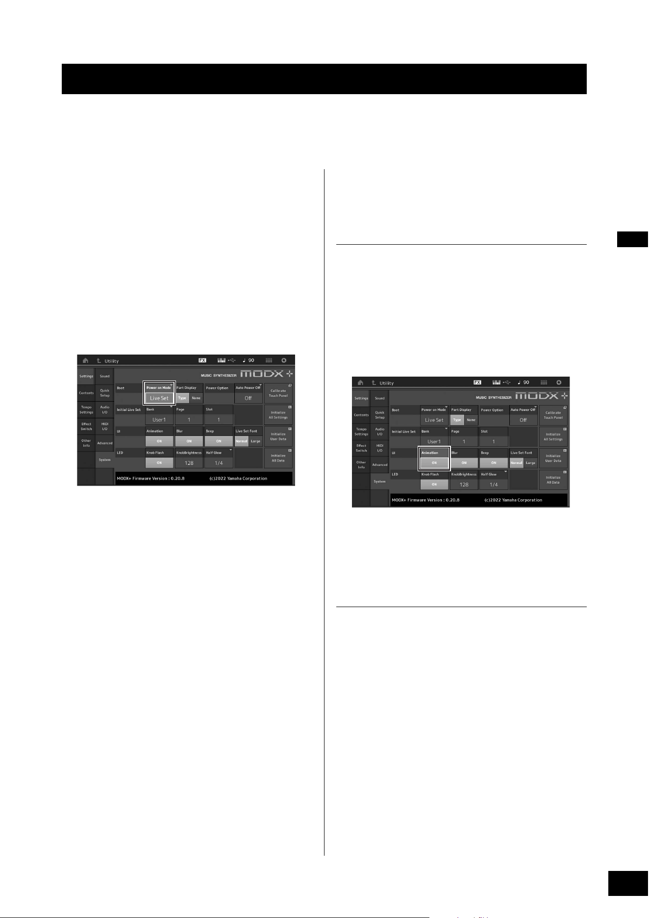
MODX+ Owner’s Manual
51
You can set various parameters in the Utility display. In particular, you can set the parameters that apply to the entire system of
this instrument by touching the [Settings] tab. The changes you make in the Utility display are activated once you press the
[EXIT] button to return to the original display. This section describes some useful functions related to the entire system settings.
Setting automatic power-on tasks
You can determine which display is automatically called up
when power is turned on: the Live Set display or the
Performance Play display.
1 Press the [UTILITY] button to call up the
Utility display, then touch [Settings] tab
[System] tab.
2 In [Power on Mode], select “Live Set” (Live
Set display) and the slot number, or
“Perform” (Performance Play display) as the
start-up display.
3 Press the [EXIT] button.
This stores the setting and returns to the previous
display.
Setting button lamp behavior
You can control the dimming of the button lamps.
1 Press the [UTILITY] button to call up the
Utility display, then touch [Settings] tab
[System] tab.
2 Set “Half Glow” to “Off,” “1/4,” or “1/2.”
When “Off” is selected, the dimming function is turned
off.
When “1/4” is selected, the brightness of the button in
the dimly lit condition is reduced to 25% of the fully lit
condition. This lighting level is suitable for dark
surroundings, such as a stage.
When “1/2” is selected, the brightness of the button in
the dimly lit condition is reduced to 50% of the fully lit
condition. This lighting level is useful in bright
surroundings (such as outdoors) when it is hard to
distinguish whether the button is dimly lit or off.
3 Press the [EXIT] button.
This stores the setting and returns to the previous
display.
Turning various functions on/off
You can set various functions by touching the [System] tab
on the Utility display.
Turning animation on/off
You can turn the animation of screen transition on/off as
follows.
1 Press the [UTILITY] button to call up the
Utility display, then touch [Settings] tab
[System] tab.
2 Select “ON” or “OFF” in “Animation” to turn
the animation on or off.
3 Press the [EXIT] button.
This stores the setting and returns to the previous
display.
Turning display blur effect on/off
When any display is selected, the display previously
selected is blurred. You can turn the function on/off as
follows.
1 Press the [UTILITY] button to call up the
Utility display, then touch [Settings] tab
[System] tab.
2 Set “Blur” to “ON” or “OFF” to turn the blur
effect on or off.
3 Press the [EXIT] button.
This stores the setting and returns to the previous
display.
Making Global System Settings
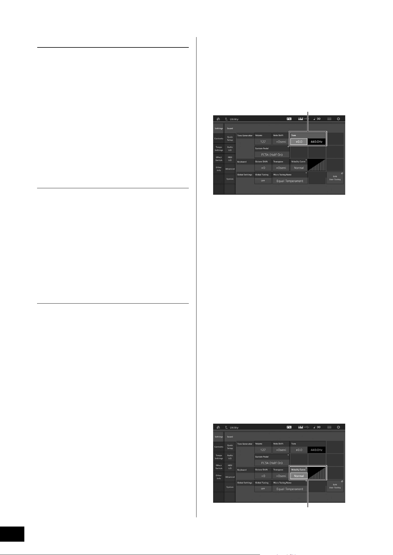
MODX+ Owner’s Manual
52
Making Global System Settings
Turning the beep sound on/off
You can turn the beep sound (that confirms operations,
menu/parameter selection, etc.) on/off as follows.
1 Press the [UTILITY] button to call up the
Utility display, then touch [Settings] tab
[System] tab.
2 Set “Beep” to “ON” or “OFF” to turn the beep
on or off.
3 Press the [EXIT] button.
This stores the setting and returns to the previous
display.
Turning the flashing of the Super Knob
on/off
In the default setting, the Super Knob flashes at the current
beat. You can turn this flashing on/off as follows.
When the function is turned off, the Super Knob remains lit
continuously.
1 Press the [UTILITY] button to call up the
Utility display, then touch [Settings] tab
[System] tab.
2 Select “ON” or “OFF” in “Knob Flash” to turn
the flashing on or off.
Touch panel calibration
Calibration of the touch panel may be necessary if the touch
panel seems occasionally unresponsive or the response is
erratic.
1 Hold down the [UTILITY] button and press the
[PART SELECT MUTE/SOLO] button.
The Utility display appears, with the [Calibrate Touch
Panel] selected.
2 Press the [ENTER] button.
3 A white square appears. Touch the square to
calibrate the touch panel, and continue with
subsequent white squares until the operation
is finished.
NOTE
Alternately, you can touch [UTILITY] [Settings] [System] to
call up the System setting display and touch [Calibrate Touch
Panel].
Changing the Master Tuning
You can adjust the tuning of the MODX+. This is useful when
playing in an ensemble to match the pitch of other
instruments which cannot be easily tuned (such as a piano).
1 Press the [UTILITY] button to call up the
Utility display, then touch [Settings] tab
[Sound] tab.
2 Select “Tune” and change the parameter by
using the Data dial.
In this example, we'll change the value from “440 Hz” to
“442 Hz.” Since the Tune parameter is actually adjusted
in cents (1 cent = 1/100th of a semitone), the
corresponding value in Hertz is shown at right. Turn the
data dial to change the value to “+8.0.” Use a tuner for
the more accurate tuning as necessary.
3 Press the [EXIT] button.
This stores the setting and returns to the previous
display.
Changing the Velocity Curve
These five curves determine how the actual velocity will be
generated and transmitted according to the velocity
(strength) with which you play notes on the keyboard. The
graph shown in the display indicates the velocity response
curve. (The horizontal line represents the received velocity
values (strength of your playing), while the vertical line
represents the actual velocity values transmitted to the
internal/external tone generators.)
1 Press the [UTILITY] button to call up the
Utility display, then touch [Settings] tab
[Sound] tab.
Tune
Velocity Curve
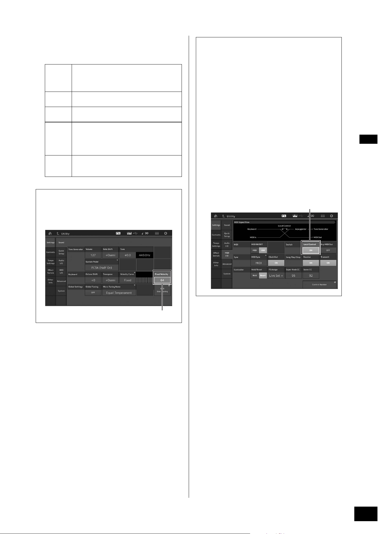
MODX+ Owner’s Manual
53
Making Global System Settings
2 Select “Velocity Curve” and change the curve
setting as desired, from the pop-up menu at
the left of the display.
3 Press the [EXIT] button.
This stores the setting and returns to the previous
display.
Changing the font size of the Live
Set
If the characters on the Live Set display or the Category
Search display are small and difficult to read, you can
increase the size of the displayed characters.
The setting display is called up via the [Utility] button
[Settings] tab
[System] tab “Live Set Font.”
For details, refer to the Reference Manual.
Normal
This linear “curve” produces one-to-one
correspondence between the strength of your
keyboard playing (velocity) and the actual sound
change.
Soft
This curve provides increased response,
especially for lower velocities.
Hard
This curve provides increased response,
especially for higher velocities.
Wide
This curve accentuates your playing strength by
producing lower velocities in response to softer
playing and louder velocities in response to
harder playing. As such, you can use this setting
to expand your dynamic range.
Fixed
This setting produces the same amount of sound
change (set in Fixed Velocity below), no matter
what your playing strength.
When the parameter of the Velocity Curve is
set to “Fixed”
The velocity of the note you play is fixed at the value set
here.
Setting the Fixed Velocity value
Setting Local Control on/off
Local Control is usually set to on; however, in some cases
(when using with a computer and sequencer program),
you may want to turn it off so that the keyboard does not
play the internal Parts, but the appropriate MIDI
information is still transmitted via the MIDI OUT terminal
when notes are played on the keyboard. Also, the input
MIDI information is appropriately processed in this
instrument.
1 Press the [UTILITY] button to call up the
Utility display and touch the [Settings]
tab at the left side of the screen
[MIDI I/O] tab.
2 Set “Local Control” to either “ON” or
“OFF.”
3 Press the [EXIT] button.
This stores the setting and returns to the previous
display.
Local Control
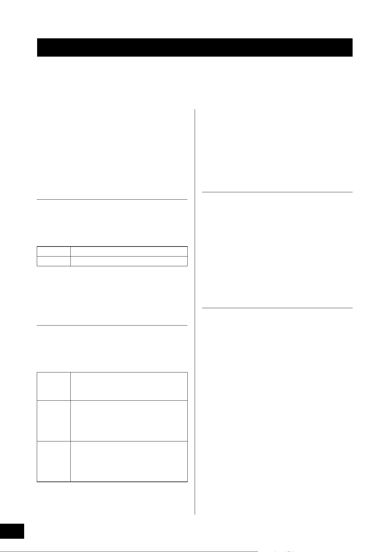
MODX+ Owner’s Manual
54
You can connect to an external MIDI device using a commercially available MIDI cable or USB cable. This allows you to control
an external MIDI device from MODX+, or play the tone generator of the MODX+ with an external MIDI keyboard or sequencer.
This section describes the settings required to use the device as intended while connecting an external MIDI device. For details
on specific connection examples, refer to the Reference Manual.
Connecting to an external MIDI
device with the MIDI [IN], [OUT]
terminals
When connecting to an external MIDI device using the MIDI
[IN] and [OUT] terminals, the following two settings related
to MIDI transmission/reception must be set correctly to
operate the device as intended.
MIDI IN/OUT
Determines whether MIDI communication with an external
device is handled through the MIDI [IN], [OUT] terminals or
the [USB TO HOST] terminal.
The setting display is called up by the [UTILITY] button
[Settings] tab [MIDI I/O] tab “MIDI IN/OUT.”
NOTE
For an external MIDI device connected via the [USB TO DEVICE]
terminal, MIDI communication is always possible regardless of this
setting.
MIDI I/O Mode
Determines the rules by which channels transmit the data of
each Part and which Part receives the data received by each
channel, when communicating with an external MIDI device.
The setting display is called up by the [UTILITY] button
[Settings] tab [Advanced] tab “MIDI I/O Mode.”
Connecting to an external MIDI
device with the [USB TO DEVICE]
terminal
You can connect an external MIDI device (such as a MIDI
keyboard) to the [USB TO DEVICE] terminal and treat it as if
it were a keyboard built into the MODX+ itself.
MIDI devices available
• USB class compliant MIDI devices
USB MIDI keyboard, etc.
• Yamaha MIDI devices whose compatibility has
been confirmed
CP1, CP4/40 STAGE, CP88/73, MODX, MONTAGE,
MOTIF XF, MOXF, MX, reface, YC
NOTICE
The rating of the [USB TO DEVICE] terminal is a maximum of 5V/
500mA. Do not connect USB devices having a rating above this,
since this can cause damage to the instrument itself.
Special notes concerning MIDI
communication
MIDI communication with a device connected via the [USB
TO DEVICE] terminal follows special rules that allow the
device to behave like a built-in keyboard.
• MIDI communication is one-way only (sent from the
external MIDI device and received by the MODX+).
• All MIDI data is received regardless of the “MIDI IN/OUT,”
“MIDI I/O Mode,” and “MIDI I/O Ch” settings.
• For Parts with Keyboard Control set to on, data received
on all corresponding channels is shared. For example,
when Keyboard Control for Parts 1 to 3 are set to on, data
received from any of channels 1 to 3 will be delivered to all
Parts 1 to 3.
• Each Part with Keyboard Control set to off receives the
data of only the corresponding channel for the Part.
• Only when “MIDI I/O Mode” is “Single,” some particular
Control Change messages sent to the channel specified
by “MIDI I/O Ch” setting are not relayed to each Part but
be received as Common parameters. In this regard, this is
the same way as communication via the MIDI [IN], [OUT]
terminals and the [USB TO HOST] terminal. For details on
the applicable Control Change messages, refer to the
“MIDI I/O Mode” section of the Reference Manual.
Connecting External MIDI Instruments
MIDI
For using the MIDI [IN], [OUT] terminals.
USB
For using the [USB TO HOST] terminal.
Multi
This is one-to-one correspondence between each
Part and each channel. For example, Part 1 data is
sent and received on channel 1 and Part 16 data is
sent and received on channel 16.
Single
Data of all Parts with Keyboard Control set to on is
sent and received on one specified channel. Data
of Parts with Keyboard Control set to off is not sent
or received.
To specify which channel is used to send and
receive data, set the “MIDI I/O Ch.”
Hybrid
Data for all Parts with Keyboard Control set to on is
sent and received in the same way as when
“Single” is set.
Data on the Part where Keyboard Control set to off
is sent and received in the same way as when
“Multi” is set.
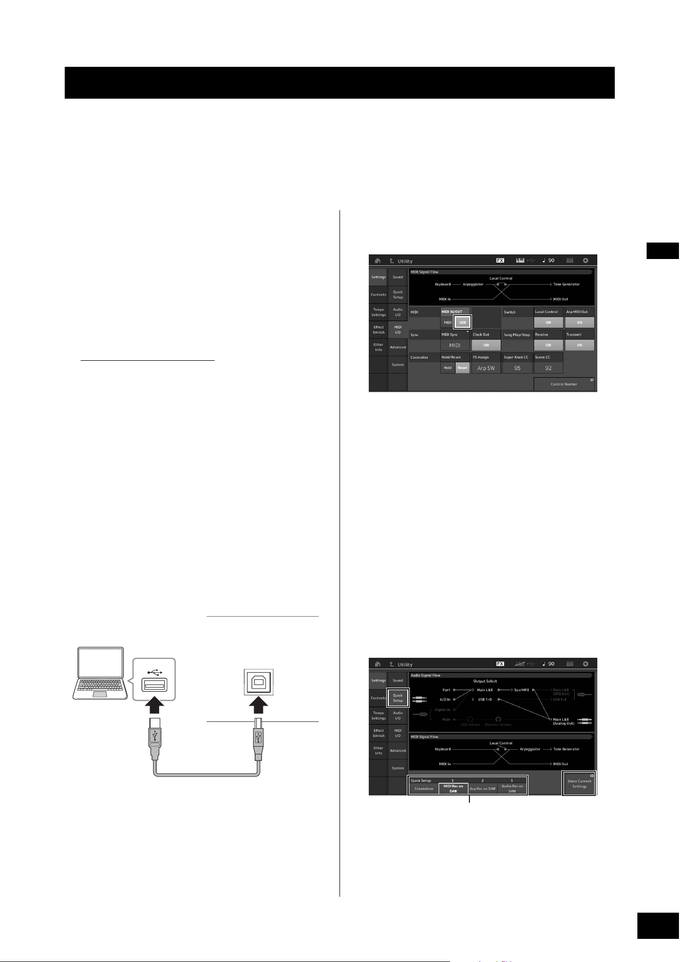
MODX+ Owner’s Manual
55
By connecting the MODX+ to your computer, you can use a DAW or sequence software on the computer to create your own
original songs.
NOTE
The acronym DAW (digital audio workstation) refers to music software for recording, editing and mixing audio and MIDI data. The main DAW
applications are Steinberg Cubase, Ableton Live, and Apple Logic.
Connecting to a computer
A USB cable and the Yamaha Steinberg USB Driver are
necessary to connect the MODX+ to the computer. Follow
the instructions below. Note that both audio data and MIDI
data can be transmitted through a USB cable.
1 Download the latest Yamaha Steinberg USB
Driver from our website.
After clicking the Download button, extract the
compressed file.
https://download.yamaha.com/
After accessing the Support website (and clicking on
“Firmware/Software”), enter the appropriate model name.
NOTE
• Information on system requirements is also available at the
above website.
• The Yamaha Steinberg USB Driver may be revised and
updated without prior notice. Make sure to check and down-
load the latest version from the above site.
2 Install the Yamaha Steinberg USB Driver to
the computer.
For instructions on installing, refer to the online
Installation Guide included in the downloaded file
package. When connecting this instrument to a
computer, connect the USB cable to the [USB TO HOST]
terminal of this instrument and the USB terminal of the
computer as shown below.
3 Press the [UTILITY] button to call up the
Utility display.
4 Touch [Settings] tab [MIDI I/O] tab at the
left side of the display.
5 Set “MIDI IN/OUT” to “USB.”
Make sure that the [USB TO HOST] terminal of this
instrument is enabled.
6 Set the input and output settings for audio
data as desired to suit your personal
preferences.
The change can be made from [UTILITY] [Settings]
[Audio I/O].
Using the Quick Setup function to change parameters
related to audio and MIDI data, lets you instantly
reconfigure the MODX+ for different computer/
sequencer related applications by simply calling up
specially programmed presets.
To do this, touch [Settings] tab [Quick Setup] tab at
the left side of the display to call up the Quick Setup
display.
Touch [Store Current Settings] to store the desired
setting in any of the 1 to 3 Quick Setups.
NOTE
For details on the parameters available for setting with the Quick
Setup function, see the Reference Manual PDF document.
Using a Connected Computer
USB terminal
[USB TO HOST] terminal
USB cable
Rear panel
Quick Setups 1 to 3

MODX+ Owner’s Manual
56
Using a Connected Computer
Precautions when using the [USB TO HOST]
terminal
When connecting the computer to the [USB TO HOST]
terminal, make sure to observe the following points to
avoid freezing the computer and corrupting or losing the
data.
NOTICE
• Use an AB type USB cable. USB 3.0 cables cannot be
used.
• Execute the following before turning the power to the
instrument on/off or plugging/unplugging the USB cable
to/from the [USB TO HOST] terminal.
-Quit any open application software on the computer.
-Make sure that data is not being transmitted from the
instrument. (Data is transmitted only by playing notes
on the keyboard or playing back a song.)
• While the computer is connected to the instrument, you
should wait for six seconds or more between these
operations: (1) when turning the power of the instrument
off then on again, or (2) when alternately connecting/
disconnecting the USB cable.
If the computer or the instrument freezes, restart the
application software or the computer OS, or turn the power
to the instrument off then on again.
Audio channels
The audio signals of the MODX+ can be output to the [USB
TO HOST] terminal and the OUTPUT [L/MONO]/[R] jacks.
When connecting to a computer, use the [USB TO HOST]
terminal. In this case, up to 10 audio channels (5 stereo
channels) are available. The output-to-channel
assignments are made as follows: [EDIT] [Part Settings]
“Part Output” in the [General] display.
The audio signals of the MODX+ can be input from the
[USB TO HOST] terminal and the A/D INPUT [L/MONO]/[R]
jacks.
Up to four channels (two stereo channels) of audio can be
input to the [USB TO HOST] terminal. Set the output level
in the Mixing display or the Performance edit display. The
signals are output to the OUTPUT [L/MONO]/[R] jacks (two
channels.) Also, up to two audio channels (one stereo
channel) can be input to the A/D INPUT [L/MONO]/[R]
jacks. The signal is sent to the A/D input part of the
MODX+. For more details, see the Reference Manual PDF
document.
Usage of each MIDI port
When this instrument is connected to a computer with the
[USB TO HOST] terminal, the computer recognizes three
MIDI ports for different usages.
For the MODX+, the usage of each port is as follows.
Select the appropriate port on the computer side,
according to the application.
Port 1: For communication between the tone
generator section of this instrument and the
computer
If you want to play the tone generator of this instrument
from your computer, or if you want your computer to
receive performance information from this instrument,
select Port 1 on your computer.
Port 2: For DAW remote function
If you want to use this instrument to remotely control
your DAW software, select Port 2 on your computer. For
details on how to set and use the DAW remote function,
refer to the Reference Manual.
Port 3: For using this instrument as a USB-MIDI
interface
If you want to connect an external MIDI device that does
not have a USB terminal to a computer via the MIDI [IN]/
[OUT] terminals of this instrument, select Port 3 on the
computer.
When “MIDI IN/OUT” (page 54) is set to “USB,” the MIDI
[IN]/[OUT] terminals of this instrument are directly
connected to Port 3, and are disconnected from the tone
generator section.
NOTE
• These Ports are only valid when “MIDI IN/OUT” (page 54) is
set to “USB.”
• Each Port can handle 16 channels of MIDI data.
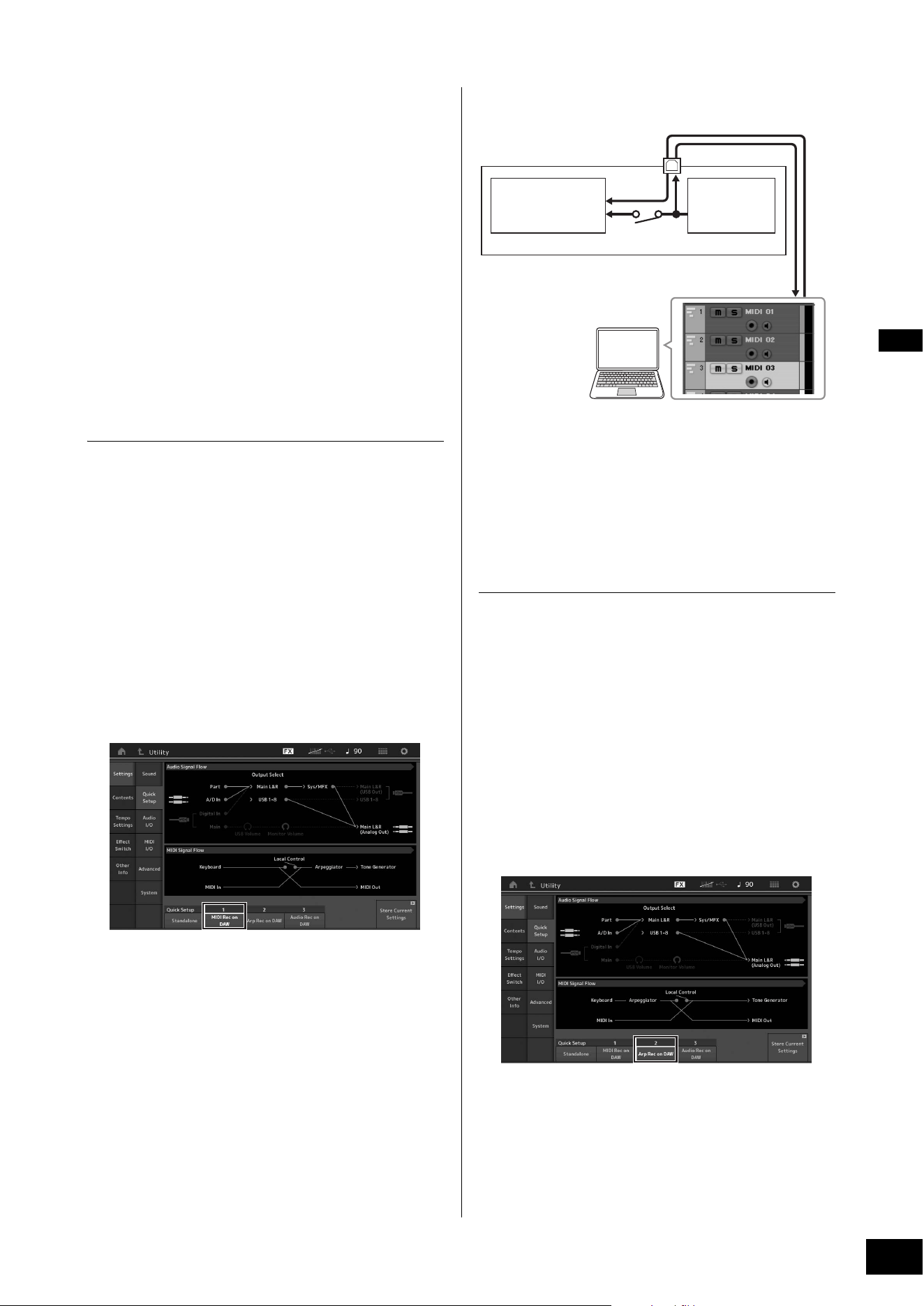
MODX+ Owner’s Manual
57
Using a Connected Computer
Creating a Song with a computer
By using the MODX+ with DAW software on a computer
connected to the MODX+, you can take advantage of the
following functions and applications.
• MIDI recording and audio recording of your MODX+
performance to the DAW software.
• Playing back a song from the DAW software by using the
MODX+ tone generator.
This section contains an overview on how to use DAW
software on the computer with the MODX+ after connecting
(page 55).
Recording your performance on the
MODX+ to computer as MIDI data (no
Arpeggio playback recorded)
In this method, you record your performance on the MODX+
to DAW simply as MIDI data. Keep in mind that Arpeggio
playback cannot be recorded.
Setting up the MODX+
1 Press the [UTILITY] button to call up the
Utility display.
2 Touch [Settings] tab [Quick Setup] tab at
the left side of the display to call up the Quick
Setup display.
3 Select “1 (MIDI Rec on DAW)” of “Quick
Setup.”
4 Press the [EXIT] button to select the
Performance you want to record.
Setting up the DAW software
1 Set MIDI Thru to “on” on the DAW software.
By setting MIDI Thru to “on,” the MIDI data generated by
playing the keyboard and transmitted to the computer
will be returned back to the MODX+. As shown in the
example below, the MIDI data transmitted from the
MODX+ then recorded to the computer via MIDI channel
1 will be returned back from the computer to the MODX+
via MIDI channel 3 according to the setting of the
recording Track. As a result, the tone generator of the
MODX+ will sound the MIDI data generated by playing
the keyboard as MIDI data from channel 3.
2 Record your MODX+ performance on the
DAW software.
Recording your performance on the
MODX+ to computer as MIDI data (with
Arpeggio playback recorded)
In this method you can record Arpeggio playback on the
MODX+ to DAW as MIDI data.
Setting up the MODX+
1 Press the [UTILITY] button to call up the
Utility display.
2 Touch [Settings] tab [Quick Setup] tab at
the left side of the display to call up the Quick
Setup display.
3 Select “2 (Arp Rec on DAW)” of “Quick
Setup.”
4 Press the [EXIT] button to select the
Performance you want to record.
Setting up the DAW software
Follow the same operations in “Recording your performance
on the MODX+ to computer as MIDI data (no Arpeggio
playback recorded).”
MODX+
[USB TO HOST] terminal
Tone generator block
(recognizing data
over MIDI Channel 3)
Keyboard
(output via MIDI
Channel 1)
Local Control = off
Computer
(Cubase, etc.)
MIDI Thru = on
IN
CH1
OUT
CH3

MODX+ Owner’s Manual
58
Using a Connected Computer
Song playback from a computer using
the MODX+ as a tone generator
The instructions below show how to use this instrument as a
MIDI tone generator. In this case, actual MIDI sequence data
is transmitted from DAW software on the computer, letting
you take advantage of the dynamic sounds of the MODX+,
while giving you the added benefit of saving processing
power on your computer by avoiding the use of software
synths.
Setting up the MODX+
1 Select the Performance to be edited.
2 Touch the [Mixing] tab on the Performance
Play display to call up the Mixing display.
3 Set up the Mixing for Parts 1–16 as
necessary.
Setting up the DAW software
1 Set the MIDI output port of the Tracks for
playing the MODX+ to Port 1 of the MODX+.
2 Enter the MIDI data to each Track of the DAW
software on the computer.
The tone generator settings of the part corresponding to
the MIDI Track will be set in the Mixing display on the
MODX+.
Controlling your DAW software from the
MODX+ (DAW remote function)
When the MODX+ is connected to your computer by a USB
cable, you can use the MODX+ to remotely control the DAW
software on your computer.
For details on how to set and use, refer to the Reference
Manual.

MODX+ Owner’s Manual
59
MEMO
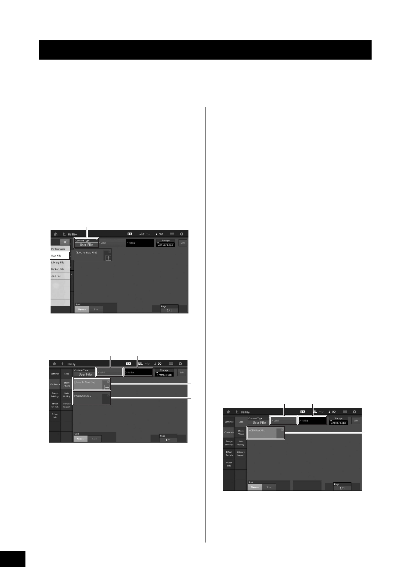
MODX+ Owner’s Manual
60
The Utility display provides tools for transferring the entire system setting and data (such as Performances and Live Sets)
between the MODX+ and a USB flash drive connected to the [USB TO DEVICE] terminal.
This section explains how to save/load all the data on the user memory of this instrument as a “User” file.
Saving the settings to a USB flash
drive
1 Connect a USB flash drive to the [USB TO
DEVICE] terminal of this instrument.
2 Press the [UTILITY] button to call up the
Utility display, and then touch the [Contents]
tab [Store/Save] tab in the left of the
display.
3 Set “Content Type” to “User File.”
4 Select the desired directory of the USB flash
drive.
1 Parent folder
2 Store-destination folder in the USB flash drive
3 New store destination
4 Existing files
5 Touch “+” in [Save As New File].
NOTE
To overwrite the existing file, touch the file name.
6 The Text input display appears. Input the file
name to be stored.
For detailed instructions on entering a name, see
“Naming (inputting characters)” in “Basic Operation and
Displays” (page 21).
7 Touch [Done] on the Text input display to
actually execute the Store operation.
NOTE
To overwrite the existing file, select “YES” on the display which
prompts you for confirmation.
Loading the settings from a USB
flash drive
NOTICE
The Load operation overwrites the existing data in this
instrument. Important data should always be saved to a USB
flash drive connected to the [USB TO DEVICE] terminal.
1 Connect a USB flash drive to the [USB TO
DEVICE] terminal of this instrument.
2 Press the [UTILITY] button to call up the
Utility display, and then touch [Contents] tab
[Load] tab at the left side of the display.
3 Set “Content Type” to “User File.”
4 Select the desired folder of the USB flash
drive.
5 Select the file (extension: .X8U) of the
memory to execute the Load operation.
1 Source USB flash drive
2 Source folder in the USB flash drive
3 Existing files
Saving/Loading Data
Select Content type
12
3
4
12
3

MODX+ Owner’s Manual
61
Saving/Loading Data
Precautions when using the [USB
TO DEVICE] terminal
This instrument features a built-in [USB TO DEVICE]
terminal. When connecting a USB device to the terminal, be
sure to handle the USB device with care. Follow the
important precautions below.
NOTE
For more information about the handling of USB devices, refer to the
owner's manual of the USB device.
Compatible USB devices
• USB flash drive (*1)
• USB class compliant MIDI devices (*2)
• Yamaha MIDI devices whose compatibility has been
confirmed (*2)
Other USB devices such as a USB hub, computer keyboard
or mouse cannot be used.
Although USB devices 1.1 to 3.0 can be used on this
instrument, the amount of time for saving to or loading from
the USB device may differ depending on the type of data or
the status of the instrument.
*1) The instrument does not necessarily support all
commercially available USB flash drives. Also, Yamaha
cannot guarantee operation of USB flash drives that you
purchase. Before purchasing a USB flash drive for use with
this instrument, confirm the compatibility of the device with
compatible device list on the following web page:
https://download.yamaha.com/
After accessing the Support website and clicking on
“Documents and Data,” enter the model name of the
instrument and click “Search.”
*2) For details on the MIDI devices that can be used and related
settings and how the devices work when connected, refer to
the “Connecting External MIDI Instruments” (page 54).
NOTICE
The rating of the [USB TO DEVICE] terminal is a maximum of 5V/
500mA. Do not connect USB devices having a rating above this,
since this can cause damage to the instrument itself.
Connecting a USB device
When connecting a USB device to the [USB TO DEVICE]
terminal, make sure that the connector on the device is
appropriate and that it is connected in the proper direction.
NOTICE
• Avoid connecting or disconnecting the USB device during
playback/recording and file management operations (such as
Save, Copy, Delete and Format), or when accessing the USB
device. Failure to observe this may result in “freezing” of the
operation of the instrument or corruption of the USB device
and the data.
• When connecting then disconnecting the USB device (and
vice versa), make sure to wait a few seconds between the two
operations.
Using USB flash drives
By connecting the instrument to a USB flash drive, you can
save data you’ve created to the connected device, as well
as read data from the connected device.
Maximum number of USB flash drives that
can be used
Only one USB flash drive can be connected to the [USB TO
DEVICE] terminal.
Formatting USB flash drive
You should format the USB flash drive only with this
instrument (page 61). A USB flash drive formatted on
another device may not operate properly.
NOTICE
The format operation overwrites any previously existing data.
Make sure that the USB flash drive you are formatting does not
contain important data.
NOTE
For details on how to format the USB flash drive, see the Reference
Manual PDF document.
To protect your data (write-protect)
To prevent important data from being inadvertently erased,
apply the write-protect provided with each USB flash drive. If
you are saving data to the USB flash drive, make sure to
disable write-protect.
Turning off the instrument
When turning off the instrument, make sure that the
instrument is NOT accessing the USB flash drive by
playback/recording or file management (such as during
Save, Copy, Delete and Format operations). Failure to do so
may corrupt the USB flash drive and the data.
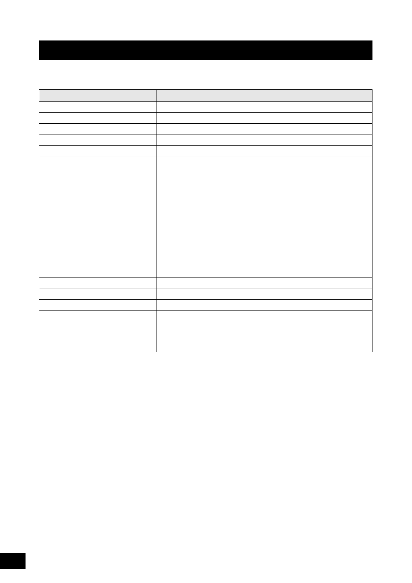
MODX+ Owner’s Manual
62
Some of the important functions and operations on the instrument can be executed with convenient panel control shortcuts.
Simply hold down the [SHIFT] button and press the indicated button (as described below).
Shift Function List
Operation Function
[SHIFT] + KNOB POSITION [1] Stores Assign 1–8 assigned to Knobs in Value 1.
[SHIFT] + KNOB POSITION [2] Stores Assign 1–8 assigned to Knobs in Value 2.
[SHIFT] + OCTAVE [-] Decreases the transpose value by 1.
[SHIFT] + OCTAVE [+] Increases the transpose value by 1.
[SHIFT] + OCTAVE [-] + OCTAVE [+] Resets the transpose value to 0.
[SHIFT] + [DEC/NO] Decreases the selected parameter value by 10.
In the Live Set display, this operation calls up the previous page.
[SHIFT] + [INC/YES] Increases the selected parameter value by 10.
In the Live Set display, this operation calls up the next page.
[SHIFT] + [ENTER] Calls up the Tempo Settings display.
[SHIFT] + [PERFORMANCE (HOME)] Calls up the Overview display.
[SHIFT] + [LIVE SET] Calls up the Live Set Register display.
[SHIFT] + [UTILITY] Calls up the Quick Setup display.
[SHIFT] + [CATEGORY] Calls up the Part Category Search display for the currently selected Part.
[SHIFT] + Slider Select [1–4] [5–8] Selects Part 9 or Part 13 when the Slider Function [PART]/[ELEMENT/OPERATOR]
button is set to “PART.”
[SHIFT] + [EDIT] Opens the Copy/Exchange dialog.
[SHIFT] + SCENE [1]–[8] Stores SCENE 1–8 in SCENE [1]–[8] buttons.
[UTILITY] + [PART SELECT MUTE/SOLO] Calls up the Touch Panel Calibration Setting display.
[SHIFT] + [AUDITION] Panel lock/unlock if the Performance Play display or Live Set display is shown.
[SHIFT] + cursor buttons Changes categories on the Category Search display (page 24):
• [SHIFT] + Left/Right: Changes main category to next/previous.
• [SHIFT] + Left + Right: Sets main category to “All.”
• [SHIFT] + Up/Down: Changes sub category to next/previous.
• [SHIFT] + Up + Down: Sets sub category to “All.”

MODX+ Owner’s Manual
63
Display Messages
LCD indication Description
** will be deleted. This message appears when the specified operation you are about to execute will
cause the specified data to be deleted.
** will be overwritten. This message appears when a file/folder having the same name as the one you
are about to save already exists.
Activate the source controller to assign. You can assign the parameter to the controller you are about to activate.
Advanced settings will be initialized. All settings executed in [Advanced] tab will be initialized.
All data and libraries will be initialized. Unsaved
user data will be lost.
All data and libraries will be initialized. Unsaved user data will be lost.
All data is initialized upon power-on. All data is initialized upon power-on.
All settings will be initialized. User data is kept. All settings will be initialized. User data is kept.
All sound will be stopped during optimization. This message appears before the internal memory is restored. All sound will be
stopped during the optimization.
All user data will be initialized. Unsaved user data
will be lost.
All user data will be initialized. Unsaved user data will be lost.
Are you sure? Confirms whether you want to execute a specified operation or not.
Arpeggio full. Appears when there are no more Arpeggio Part Switches to turn ON.
Assignable Knob Full. Appears when all of the Assignable Knobs are in use and no more Super Knob
settings can be added.
Audio Rec stopped due to lack of memory space. The USB flash drive is full and no more audio recording data can be saved. Use a
new USB flash drive, or make space by erasing unwanted data from the USB
flash drive.
Auto power off disabled. This message appears before Auto Power Off is disabled.
Bulk data protected. Bulk data cannot be received because of the setting.
Can’t process. The MODX+ cannot process a requested operation.
Completed. The specified load, save, format, or other Job has been completed.
Connecting to USB device... Currently recognizing the USB flash drive connected to the [USB TO DEVICE]
terminal.
Control Assign Full. All Control Assigns are in use.
Copy protected. You have attempted to export or save a copy-protected digital audio source.
Current user data will be overwritten by **. This message appears when saving a file, and user data under that name already
exists.
Data memory full. The internal memory is full, preventing storing of the recorded data in the Library.
Device number is off. Bulk data cannot be transmitted/received since the device number is off.
Device number mismatch. Bulk data cannot be transmitted/received since the device numbers do not
match.
File is not found. The specified file was not found during a Load operation.
File or folder already exists. A file/folder having the same name as the one you are about to save already
exists.
File or folder path is too long. The file or folder you tried to access cannot be accessed because the maximum
amount of characters indicating the path has been exceeded.
Folder is not empty. You have attempted to delete a folder that contains data.
Illegal bulk data. An error occurred while receiving a Bulk data or Bulk Request message.
Illegal file name. The specified file name is invalid. Try entering a different name.
Illegal file. The specified file is unusable by this synthesizer or cannot be loaded.
Keybank full. The maximum overall number of Key Banks has been exceeded when executing
a Load operation.
MODX+ Owner’s Manual
64
Display Messages
Library full. The maximum overall number of Libraries has been exceeded when executing
the related operations.
MIDI buffer full. Failed to process the MIDI data because too much data was received at one time.
MIDI checksum error. An error occurred when receiving bulk data.
Modified: Common AsgnKnob? Appears when the Control Assign settings for Common/Audio Edit are
automatically added or modified when you add or modify the settings for the
Assignable knobs that are associated to the Super Knob in the Control Assign
display for the Part Edit.
No data. This message appears when the selected track or range contains no data. Select
an appropriate track or range.
No read/write authority to the file. Indicates that you do not have the authority to read/write the file.
Now initializing all data… Indicates this synthesizer is restoring the factory-programmed settings.
Now initializing… Indicates that the specified data is being initialized.
Now loading... Indicates that a file is being loaded.
Now receiving MIDI bulk data... Indicates this synthesizer is receiving MIDI bulk data.
Now saving... Indicates that a file is being saved.
Now transmitting MIDI bulk data... Indicates this synthesizer is transmitting MIDI bulk data.
Part Full. All Parts are in use.
Please connect USB device. Connect the USB device to the [USB TO DEVICE] terminal for audio recording.
Please keep power on. The data is being written to Flash ROM. Never attempt to turn off the power while
data is being written to Flash ROM. Turning the power off while this message is
shown results in loss of all user data and may cause the system to freeze (due to
corruption of data in the Flash ROM). This may also result in the MODX+ being
unable to properly start up the next time the power is turned on.
Please reboot to enable the new Audio I/O Mode. Please reboot this synthesizer to activate the change of the input/output settings
for audio data.
Please reboot to maintain internal memory. Please reboot this synthesizer to restore the internal memory.
Please stop audio play/rec. The operation you have attempted to execute cannot be done during audio
recording or playback.
Please stop sequencer. The operation you have attempted to execute cannot be done during Song
playback.
Please wait… Indicates this synthesizer is executing the specified operation.
Recall latest edits. If you are editing a Performance and select a different Performance without
storing your edited one, all the edits you’ve made will be erased. If this happens,
you can use Recall to restore the Performance with your latest edits intact.
Redo last recording. Confirms whether you want to redo the operation you have undone.
Sample is protected. The sample data cannot be overwritten.
Sample is too long. The Sample size is too large and the Load operation cannot be executed.
Sample memory full. The Sample memory is full and further Load operations cannot be executed.
Scene stored. The Scene has been stored to one of the [SCENE] buttons.
Song data overload. The Song size is too large for playback.
Song full. The maximum overall number of Songs has been exceeded when executing the
related operations.
Touch the white square. This message appears when you need to touch the displayed white rectangle
during touch panel calibration.
Turn on Memory Switch to memorize ** into this
scene.
When the [Memory] (Memory Switch) is turned on for the function, the
corresponding function information is automatically stored in the currently
selected [SCENE] button.
Undo last recording. Confirms whether you want to undo the most recent recording.
Unsupported USB device. This message appears when an unsupported USB device has been connected.
USB connection terminated. A break in the connection with the USB flash drive has occurred because of an
abnormal electric current. Disconnect the USB flash drive from the [USB TO
DEVICE] terminal, and then press any of the panel buttons.
LCD indication Description

MODX+ Owner’s Manual
65
Display Messages
USB device is full. The USB flash drive is full and no more data can be saved. Use a new USB flash
drive, or make space by erasing unwanted data from the storage device.
USB device is write-protected. This message appears when you have attempted to write to a protected USB
flash drive.
USB device read/write error. An error occurred while reading or writing to/from a USB flash drive.
USB device will be formatted. This message appears before the USB device is formatted.
Waveform full. The maximum overall number of Waveforms has been exceeded when executing
the related operations.
LCD indication Description

MODX+ Owner’s Manual
66
No sound? Wrong sound? When a problem like this occurs, please check the following points before assuming that the product
is faulty. Many problems can be solved by executing Data Initialization (page 19), after backing up your data to a USB flash
drive (page 60). If the problem persists, consult your Yamaha dealer.
Touch panel does not respond correctly.
Is the point you touch on the touch panel lined up properly with the target item in the display underneath?
Calibrate the touch panel.
No Sound.
Are all sliders set to appropriate levels (other than zero or minimum)?
Is the MODX+ properly connected to related external equipment (e.g., amplifier, speaker, headphones) via audio cables?
Since the MODX+ has no built-in speakers, you will need an external audio system or a set of stereo headphones to properly
monitor it (page 18).
Is the power of this synthesizer and any external equipment connected to this synthesizer turned on?
Have you made all the appropriate level settings—including the Master Volume on this synthesizer and the volume settings on
any connected external equipment?
When the Foot Controller is connected to the [FOOT CONTROLLER] jack, press the Foot Controller down.
Is the Local Control parameter set to off?
When the Local Control parameter is set to off, no sound is produced even if you play the keyboard.
Is a blank Part selected?
If so, assign any sound to the Part or select another Part.
Is the Mute switch for each Part turned on?
When the Mute switch is turned on, no sound is produced even if you play the keyboard.
Is the Keyboard Control of each Part turned off?
Is the “Arp Play Only” parameter of each Part turned on?
When this parameter is turned on, the corresponding Part produces sound only via Arpeggio playback.
Are the MIDI volume or MIDI expression settings too low when using the external controller?
Are the effect and filter settings appropriate?
If you are using a filter, try changing the cutoff frequency. Some cutoff settings may filter out all of the sound.
• In case of Normal Part (AWM2) and Drum Part
• In case of Normal Part (FM-X)
Is “Vocoder” selected as the Insertion Effect Type of the Part?
If so, set the parameters related to the A/D INPUT [L/MONO]/[R] jacks to the appropriate values then play the keyboard while
inputting your voice into the microphone connected to the MODX+. Check whether or not the A/D INPUT [GAIN] Knob on the
rear panel is set to the minimum position.
Troubleshooting
[UTILITY] + [PART SELECT MUTE/SOLO] [ENTER]
[UTILITY] [Settings] [System] [Calibrate Touch Panel]
[UTILITY] [Settings] [MIDI I/O] “Local Control”
[PERFORMANCE (HOME)] Part “Mute”
[PART SELECT MUTE/SOLO] “Mute” Part selection
[PERFORMANCE (HOME)] Part “Kbd Ctrl”
[PERFORMANCE (HOME)] Part selection [EDIT] [Part Settings] [General] “Arp Play Only”
[PERFORMANCE (HOME)] Part selection [EDIT] [Arpeggio] [Common] “Arp Play Only”
[PERFORMANCE (HOME)] [EDIT] [Effect]
[PERFORMANCE (HOME)] Part selection [EDIT] [Effect]
[PERFORMANCE (HOME)] Part selection [EDIT] Element/Key selection [Filter]
[PERFORMANCE (HOME)] Part selection [EDIT] Operator selection [Pitch/Filter]
[EDIT] Part selection Element/Key/Operator [Common] [Effect] [Routing]

MODX+ Owner’s Manual
67
Troubleshooting
Are the volume or expression settings too low?
• In case of Normal Part (AWM2) and Drum Part
• In case of Normal Part (FM-X)
Are the parameter settings such as Element Switch, Note Limit, Velocity Limit, and Velocity Offset appropriate?
• In case of Normal Part (AWM2) and Drum Part
• In case of Normal Part (FM-X)
Is the Mute switch for each Element/Operator of Part turned on?
In case of Normal Part (FM-X), is the Carrier Level is set to “0”?
Is the output parameter of each Part turned off?
No sound from the A/D INPUT jacks.
Is the switch of the microphone turned on?
Check the microphone type. Make sure to use a dynamic microphone.
Is the cable between the microphone or audio equipment and this instrument properly connected?
Is the A/D INPUT [GAIN] knob turned to the minimum?
Is the A/D INPUT [ON/OFF] button turned on?
Check whether or not the connection status of the A/D INPUT [L/MONO]/[R] matches the “Mono/Stereo” parameter.
Check whether or not the “Mic/Line” parameter is set to the appropriate value.
When the output level of the connected equipment (such as a microphone) is low, set this parameter to “Mic.” When the
output level of the connected equipment (such as a synthesizer keyboard, CD player) is high, set this parameter to “Line.”
Are the volume settings of the A/D Input Part too low?
Are the effect settings appropriate?
Is the output setting of the A/D Input Part set appropriately?
Check whether or not the Vocoder Effect is selected.
When Vocoder is selected as the Insertion Effect for the current Part, the audio signal input from the A/D INPUT [L/MONO]/[R]
jacks may not produce any sound depending on the parameter settings.
[UTILITY] [Settings] [Sound] Tone Generator “Volume”
[EDIT] [General] “Volume”
[EDIT] Part selection Element/Key/Operator [Common] [Part Settings] [General] “Volume”
[EDIT] Part selection Element/Key/Operator [Common] [Part Settings] [General] “Dry Level”
[EDIT] Part selection Element/Key selection [Amplitude] [Level/Pan] “Level”
[EDIT] Part selection Operator selection [Level] “Level”
[EDIT] Part selection Element/Key/Operator [Common] [Part Settings] [General]
[EDIT] Part selection Element/Key selection [Osc/Tune]
[EDIT] Part selection Element/Key/Operator [Common] [Part Settings] [General]
[EDIT] Part selection Mute Switch of each Element/Operator
[EDIT] Part selection Operator selection [Level] “Level”
[EDIT] Part selection Element/Key/Operator [Common] [Part Settings] [General] “Part Output”
[EDIT] [Audio In] [Mixing] A/D In “Input Mode”
[UTILITY] [Settings] [Audio I/O] “A/D Input”
[EDIT] [Audio In] [Mixing] A/D In “Volume”
[EDIT] [Audio In] [Routing]
[UTILITY] [Settings] [Audio I/O] Output
[EDIT] Part selection Element/Key/Operator [Common] [Effect] [Routing]

MODX+ Owner’s Manual
68
Troubleshooting
Playback continues without stopping.
When the [ARP ON/OFF] button is turned on, press it so that the button is turned off.
When in the Song display, press the [J] (Stop) button.
When the effect sound such as Delay continues, check the effect setting or select the Performance again.
When the click sound continues, check the following parameter setting. Set this parameter to something other than “always,”
since this setting always plays back the click sound regardless of the sequencer status.
Distorted sound.
Are the effect settings appropriate?
Use of an effect at certain settings may produce distortion.
Are the filter settings appropriate?
Excessively high filter resonance settings can cause distortion.
• In case of Normal Part (AWM2) and Drum Part
• In case of Normal Part (FM-X)
Are any of the following volume parameters set so high that clipping is occurring?
• In case of Normal Part (AWM2) and Drum Part
• In case of Normal Part (FM-X)
Sound is cut off.
Is the entire sound (via your keyboard playback and Song/Part/Arpeggio playback) exceeding the maximum polyphony (128
for AWM2 and 128 for FM-X) of the MODX+?
Only one note sounds at a time.
When this situation occurs, the Mono/Poly parameter in the current mode is set to “mono.”
If you wish to play chords, set this parameter to “poly.”
Pitch or intervals are wrong.
Is the Master Tune parameter of each Part set to a value other than “0”?
Is the Note Shift parameter of each Part set to a value other than “0”?
• In case of Normal Part (AWM2) and Drum Part
• In case of Normal Part (FM-X)
[UTILITY] [Tempo Settings] Click “Mode”
[EDIT] Part selection Element/Key/Operator [Common] [Effect]
[EDIT] Part selection Element/Key selection [Filter]
[EDIT] Part selection Element/Key/Operator [Common] [Pitch/Filter]
[UTILITY] [Settings] [Sound] Tone Generator “Volume”
[UTILITY] [Settings] [Audio I/O] “Output”
[EDIT] [General] “Volume”
[EDIT] Part selection Element/Key/Operator [Common] [Part Settings] [General] “Volume”
[EDIT] Part selection Element/Key selection [Amplitude] [Level/Pan] “Level”
[EDIT] Part selection Operator selection [Level] “Level”
[EDIT] Part selection Element/Key/Operator [Common] [Part Settings] [General] “Mono/Poly”
[UTILITY] [Settings] [Sound] Tone Generator “Tune”
[EDIT] Part selection Element/Key/Operator [Common] [Part Settings] [Pitch] “Note Shift”
[EDIT] Part selection Element/Key/Operator [Common] [Part Settings] [Pitch] “Detune”
[EDIT] Part selection Element/Key/Operator [Common] [Pitch/Filter] [Pitch] “Note Shift”
[EDIT] Part selection Element/Key/Operator [Common] [Pitch/Filter] [Pitch] “Detune”

MODX+ Owner’s Manual
69
Troubleshooting
When the Part produces a wrong pitch, is the appropriate tuning system selected from the Micro Tuning parameter?
• In case of Normal Part (AWM2)
• In case of Normal Part (FM-X)
When the Part produces a wrong pitch, is the LFO Pitch Modulation Depth set too high?
• In case of Normal Part (AWM2)
• In case of Normal Part (FM-X)
When a Part produces a wrong pitch, are Coarse tune and Fine tune settings appropriate?
• In case of Normal Part (AWM2) and Drum Part
• In case of Normal Part (FM-X)
When the Part seems to produce the wrong pitch, is the destination of the controller set to “Pitch”?
No effect is applied.
Is the Effect Switch turned off?
Is the Variation Send or Reverb Send set to a value other than “0”?
Is the Variation Return or Reverb Return set to a value other than “0”?
Have any or all of the Element/Keys’ Insertion Effect Output parameters been set to “thru” in the effect setting?
In case of System Effect, have any or all of the effect types been set to “No Effect”?
In case of Insertion Effect, have any or all of the effect types been set to “Thru”?
Check whether the Insertion Switch parameters are set properly or not.
Have you exceed the number of Parts for applying Insertion Effect?
For Parts 9 -16, you can apply Insertion Effects to up to 4 Parts.
Cannot start the Arpeggio.
Check whether the [ARP ON/OFF] button is turned on or off.
Count the number of Parts whose Arpeggio switches are turned on.
You can play back the Arpeggios of up to eight Parts simultaneously.
Are the Arpeggio related parameters such as Note Limit and Velocity Limit set appropriately?
[EDIT] Part selection Element/Key/Operator [Common] [Part Settings] [Pitch] “Micro Tuning Name”
[EDIT] Part selection Element/Key/Operator [Common] [Pitch/Filter] [Pitch] “Micro Tuning Name”
[EDIT] Part selection Element selection [Element LFO] “Pitch Mod”
[EDIT] Part selection Element/Key/Operator [Common] [Mod/Control] [2nd LFO] “Pitch Modulation”
[EDIT] Part selection Element/Key selection [Osc/Tune] “Coarse”
[EDIT] Part selection Element/Key selection [Osc/Tune] “Fine”
[EDIT] Part selection Operator selection [Form/Freq] “Coarse”
[EDIT] Part selection Operator selection [Form/Freq] “Fine”
[EDIT] Part selection [Mod/Control] [Control Assign] “Destination”
[UTILITY] [Effect Switch]
[EDIT] Part selection Element/Key/Operator [Common] [Effect] [Routing] “Var Send”
[EDIT] Part selection Element/Key/Operator [Common] [Effect] [Routing] “Rev Send”
[EDIT] [Effect] [Routing] “Var Return”
[EDIT] [Effect] [Routing] “Rev Return”
[EDIT] Part selection Element/Key/Operator [Common] [Effect] [Routing] “Element 1–8”
[EDIT] Part selection Element/Key/Operator [Common] [Effect] [Ins A]/[Ins B]
[EDIT] Part selection Element/Key/Operator [Common] [Effect] [Ins Assign]
[EDIT] Part selection Element/Key/Operator [Common] [Arpeggio] [Common]

MODX+ Owner’s Manual
70
Troubleshooting
Is the Arpeggio Type parameter set to “off”?
Check the Arpeggio Switch parameter.
If this parameter for the current Part is set to off, Arpeggio playback will not be triggered by your keyboard performance even
if the [ARP ON/OFF] button is turned on.
Is the [Arp Bypass] button set to “on”?
Cannot stop the Arpeggio.
When Arpeggio playback does not stop even if you release the key, set the Arpeggio Hold parameter to “off.”
The Song cannot be started even when pressing the [R] (Play) button.
Does the selected Song actually contain data?
Song cannot be recorded.
Is there enough free memory for recording?
MODX+ memory can record up to 128 Songs. If the memory becomes full, no more recording is possible.
Data communication between the computer and the MODX+ does not work properly.
Check whether the Port settings on the computer are appropriate or not.
Check whether or not the MIDI IN/OUT parameter is set to the appropriate value.
MIDI bulk data transmission/reception does not work properly.
Is the Receive Bulk parameter set to off?
Set the Receive Bulk parameter to on.
When receiving MIDI bulk data transmitted via the Bulk Dump function and recorded to the external MIDI device, you need to
set the MIDI Device Number to the same value as when transmitting.
When transmission does not work properly, is the device number of the MIDI instrument connected to the MODX+ set to
match the Device Number parameter?
Cannot save data to the USB flash drive.
Is the USB flash drive being used write protected? (Write-protect should be set to off for saving data.)
Is there enough free space on the USB flash drive?
In the Contents display, set the device to the USB flash drive. Check the amount of currently available (unused) memory of the
USB flash drive indicated at the right top of the display.
Is operation of the particular USB flash drive guaranteed by Yamaha?
For details, see page 61.
In the display, there are some black points (unlit) or white points (always lit).
These are the result of defective pixels and occasionally occur in LCD; they do not indicate a problem in operation.
[EDIT] Part selection [Arpeggio] [Individual] “Name”
[PERFORMANCE (HOME)] Part selection “Arp On”
[UTILITY] [Effect Switch]
[EDIT] Part selection Element/Key/Operator [Common] [Arpeggio] [Common] “Hold”
[UTILITY] [Settings] [MIDI I/O] MIDI “MIDI IN/OUT”
[UTILITY] [Settings] [Advanced] MIDI “Receive Bulk”
[UTILITY] [Settings] [Advanced] MIDI “Device Number”
[UTILITY] [Settings] [Advanced] MIDI “Device Number”
[UTILITY] [Contents] [Load]/[Store/Save]

MODX+ Owner’s Manual
71
Specifications
Keyboards
MODX8+: 88 keys, GHS Keyboard (Initial Touch)
MODX7+: 76 keys, Semi-weighted Keyboard (Initial Touch)
MODX6+: 61 keys, Semi-weighted Keyboard (Initial Touch)
Ton e
Generator
block
Tone Generator Motion Control Synthesis Engine
AWM2: 8 Elements
FM-X: 8 Operators, 88 Algorithms
Polyphony AWM2: 128 (max.; stereo/mono waveforms)
FM-X: 128 (max.)
Multi Timbral Capacity 16 Parts (internal), Audio Input Parts (A/D
*1
, USB
*1
)
*1 stereo Part
Waveforms Preset: 5.67 GB (when converted to 16-bit linear format), User: 1.75 GB
Performances 2,227
Filters 18 types
Effect System Reverb x 12 types, Variation x 88 types, Insertion (A, B) x 88 types
*2
, Master Effect x 26 types
*2 A/D part insertion x 83 types
<Preset settings for parameters of each effect type are provided as templates>
Master EQ (5 bands), 1st part EQ (3 bands), 2nd part EQ (2 bands)
Sequencer
block
Note Capacity Approx. 130,000 notes (per Pattern or Song)
Storage Size Approx. 520,000 notes (for Patterns) and approx. 520,000 notes (for Songs)
Note Resolution 480 ppq (parts per quarter note)
Tempo (BPM) 5–300
Patterns Max. quantity 128 Patterns
Tracks 16 Sequence tracks
Recording type Real time replace, Real time overdub
Songs Max. quantity 128 Songs
Tracks 16 Sequence tracks, Tempo track, Scene track
Recording type Real time replace, Real time overdub, Real time punch in/out
Sequence Format MODX original format, SMF formats 0, 1
Arpeggio Part 8 Parts simultaneous (max.)
Preset 10,239 types
User 256 types
Motion
Sequencer
Lane 8 + 1 Lanes (max.)
Others
Live Sets Preset: 256 and more, User: 2,048
Controllers Master Volume, AD Input Gain knob, USB Volume, Pitch Bend wheel, Modulation wheel,
Control Sliders x 4, Knobs x 4, Super Knob, Data dial
Display 7" TFT Color Wide VGA LCD touch screen
Connectors [USB TO DEVICE], [USB TO HOST], MIDI [IN]/[OUT], FOOT CONTROLLER [1]/[2],
FOOT SWITCH [ASSIGNABLE]/[SUSTAIN], OUTPUT [L/MONO]/[R] (6.3 mm, standard phone jacks),
[PHONES] (6.3 mm, standard stereo phone jack),
A/D INPUT [L/MONO]/[R] (6.3 mm, standard phone jacks)
USB Audio
Interface
Sampling
Frequency
44.1 kHz
Channels In: 4 channels (2 stereo channels)
Out: 10 channels (5 stereo channels)
AC Adaptor PA-150 or an equivalent recommended by Yamaha (Output: DC 12 V, 1.5 A)
Power Consumption 16 W (when using PA-150B AC adaptor)
Standby Power Consumption 0.3 W
Dimensions, Weight MODX8+: 1,333 (W) × 404 (D) × 160 (H) mm (52-1/2" x 15-7/8" x 6-1/16"), 13.8 kg (30 lbs 7 oz)
MODX7+: 1,144 (W) × 331 (D) × 134 (H) mm (45-1/16" x 13-1/16" x 5-1/4"), 7.4 kg (16 lbs 5 oz)
MODX6+: 937 (W) × 331 (D) × 134 (H) mm (36-7/8" x 13-1/16" x 5-1/4"), 6.6 kg (14 lbs 9 oz)

MODX+ Owner’s Manual
72
Specifications
* The contents of this manual apply to the latest specifications as of the publishing date. To obtain the latest manual, access the Yamaha website then
download the manual file. Since specifications, equipment or separately sold accessories may not be the same in every locale, please check with your
Yamaha dealer.
GNU GENERAL PUBLIC LICENSE
GNU LESSER GENERAL PUBLIC LICENSE
Note on source code distribution
For three years after the final factory shipment, you may request from Yamaha the source code for any portions of the product which are licensed under the
GNU General Public License or GNU Lesser General Public License by writing to the following address:
DMI Strategy Planning Group, DMI Division
Digital Musical Instruments Division
YAMAHA Corporation
10-1 Nakazawa-cho, Chuo-ku, Hamamatsu, 430-8650, JAPAN
The source code will be provided at no charge; however, we may require you to reimburse Yamaha for the cost of delivering the source code to you.
• Note that we shall bear no responsibility whatsoever for any damage arising from changes (additions/ deletions) made to the software for this product by
a third party other than Yamaha (or party authorized by Yamaha).
• Note that re-use of source code released to the public domain by Yamaha is unguaranteed, and Yamaha shall not bear any responsibility whatsoever for
the source code.
• The source code can be downloaded from the following address:
https://download.yamaha.com/sourcecodes/synth/
Others
Accessories AC adaptor (PA-150B or an equivalent recommended by Yamaha*), Owner’s Manual (this book),
Cubase AI Download Information
* May not be included depending on your area. Check with your Yamaha dealer.

MODX+ Owner’s Manual
73
A
A/D INPUT [GAIN] knob ........................................................... 10
A/D INPUT [L/MONO]/[R] jacks................................................ 17
A/D INPUT [ON/OFF] button..................................................... 10
ABS (Audio Beat Sync)............................................................. 17
[ARP ON/OFF] (Arpeggio on/off) button................................... 11
Arpeggio ................................................................................... 28
Arpeggio type ........................................................................... 43
[ASSIGN 1] and [ASSIGN 2] buttons
(Assignable switches 1 and 2) ................................................. 11
[ASSIGN] button ....................................................................... 12
Audio channel........................................................................... 56
[AUDITION] button ................................................................... 15
Audition phrase......................................................................... 25
Auto Power Off.......................................................................... 19
C
Carrier ....................................................................................... 38
[CATEGORY] button ................................................................. 15
Category Search....................................................................... 24
Compare function ..................................................................... 40
[CONTROL ASSIGN] button ..................................................... 13
Control Sliders 1–4 (5–8/9–12/13–16)....................................... 12
Controllers................................................................................. 29
Cursor buttons .................................................................... 14, 20
D
Data dial.................................................................................... 14
DAW (digital audio workstation) ............................................... 55
[DC IN]...................................................................................... 17
[DEC/NO] button....................................................................... 14
Display Messages .................................................................... 63
Drum Part.................................................................................. 22
E
[EDIT] button............................................................................. 14
Effect......................................................................................... 39
Element Common Edit .............................................................. 38
Element Edit.............................................................................. 38
[ENTER] button ......................................................................... 14
Envelope Follower............................................................... 17, 44
[EXIT] button ............................................................................. 14
F
Flag ........................................................................................... 23
FM ............................................................................................. 38
FOOT CONTROLLER [1]/[2] jacks ........................................... 17
FOOT SWITCH [ASSIGNABLE]/[SUSTAIN] jacks .................... 17
Formatting................................................................................. 61
Frequency modulation .............................................................. 38
G
GM ............................................................................................ 22
GM Bank ................................................................................... 22
H
Headphones..............................................................................18
I
[INC/YES] button .......................................................................14
Initial factory settings.................................................................19
Initialized Performance..............................................................25
Inputting on the keyboard .........................................................21
Inputting on the numeric keypad ..............................................21
K
Key Common Edit......................................................................38
Key Edit .....................................................................................38
Keyboard...................................................................................10
Knob Function [TONE]/[EG/FX]/[EQ]/[ARP/MS] button ............12
KNOB POSITION [1] and [2] buttons........................................13
Knobs ........................................................................................30
Knobs 1–4 (5–8) ........................................................................12
L
Layer .........................................................................................41
Library Bank ..............................................................................22
Live Set................................................................................23, 35
[LIVE SET] button ......................................................................15
Live Set display .........................................................................20
Loading .....................................................................................60
Local Control .............................................................................53
M
Master Tuning............................................................................52
MASTER VOLUME.....................................................................10
[MASTER VOLUME] knob .........................................................10
Microphone ...............................................................................50
MIDI [IN], [OUT] terminals.........................................................17
MIDI port....................................................................................56
MIDI Recording .........................................................................45
Mixing........................................................................................33
Modulation wheel ......................................................................10
Modulator ..................................................................................38
[MOTION SEQ HOLD] (Motion Sequencer hold) button...........11
[MOTION SEQ TRIGGER] (Motion Sequencer trigger) button..11
Motion Sequencer .....................................................................28
[MS ON/OFF] (Motion Sequencer on/off) button.......................11
Multi Part Performance ..............................................................22
Mute function.............................................................................27
N
Normal Part (AWM2)..................................................................22
Normal Part (FM-X)....................................................................22
Index

MODX+ Owner’s Manual
74
Index
O
OCTAVE [-] and [+] buttons ..................................................... 11
Operator.................................................................................... 38
Operator Common Edit............................................................. 38
Operator Edit ............................................................................ 38
OUTPUT [L/MONO] and [R] jacks............................................ 17
P
Panel Lock ................................................................................ 62
Part Control status .................................................................... 30
Part Editing ............................................................................... 38
[PART SELECT MUTE/SOLO] button........................................ 15
Performance ............................................................................. 22
[PERFORMANCE (HOME)] button............................................ 14
Performance Control status ...................................................... 30
Performance Edit display.......................................................... 37
Performance Editing ................................................................. 37
Performance Play...................................................................... 26
Performance Play display ......................................................... 20
[PHONES] (Headphone) jack ................................................... 17
Pitch Bend wheel ...................................................................... 10
Power ........................................................................................ 18
Power-on tasks ......................................................................... 51
Preset Bank............................................................................... 22
Punch In/Out ............................................................................. 46
Q
Quick Setup .............................................................................. 55
R
Realtime Recording .................................................................. 45
Redo ......................................................................................... 47
Rhythm Part .............................................................................. 43
Rhythm Pattern ......................................................................... 43
[RHYTHM PATTERN] button..................................................... 13
S
Saving ....................................................................................... 60
SCENE [1/5] [2/6] [3/7] [4/8] buttons........................................ 12
Scene function .......................................................................... 34
Scene Select [1–4] [5–8] button ............................................... 12
SEQ TRANSPORT button.......................................................... 13
[SHIFT] button........................................................................... 14
Single Part Performance ........................................................... 22
Slider Function [PART]/[ELEMENT/OPERATOR] button........... 12
Slider Select [1–4] [5–8] button ................................................ 12
Solo function ............................................................................. 27
Song.................................................................................... 45, 47
Split ........................................................................................... 42
SSS (Seamless Sound Switching) ............................................ 23
[P] (Standby/On) switch .......................................................... 17
Store.......................................................................................... 37
[STORE] button......................................................................... 14
Super Knob......................................................................... 13, 31
T
Touch panel LCD...................................................................... 13
Track ......................................................................................... 45
U
Undo..........................................................................................47
[USB TO DEVICE] terminal..................................................17, 61
[USB TO HOST] terminal.....................................................17, 56
[USB VOLUME (MONITOR)] knob ............................................10
User Bank..................................................................................22
[UTILITY] button ........................................................................14
Y
Yamaha Steinberg USB Driver ..................................................55
Z
Zone ..........................................................................................49

75
MEMO
76
Deutsch
Français
Nederlands
Español
Italiano
Português
Ελληνικά
Svenska
Norsk
Dansk
Suomi
Polski
Čeština
Magyar
Eesti
Latviešu
Lietuvių
Slovenčina
Slovenščina
Български
Română
English
Hrvatski
Türkçe
Important Notice: Power management information for customers in European Economic Area (EEA),
Switzerland and Turkey
Remarque importante : Informations sur la gestion de l'alimentation pour les clients de l'Espace
économique européen (EEE), de Suisse et de Turquie
Yamaha-Produkte sind mit einer Power-Management-Funktion ausgestattet. Bei einigen Produkten können Sie diese Funktion ausschalten oder
die Zeitdauer, die verstreicht, bis das Instrument ausgeschaltet oder in Bereitschaft versetzt wird, verlängern. In diesen Fällen erhöht sich der
Energieverbrauch.
Les produits Yamaha sont équipés d’une fonction de gestion de l’alimentation. Certains produits vous permettent de désactiver cette fonction ou
d'allonger le délai avant la mise hors tension ou la mise en veille. Dans ces cas, la consommation d’énergie augmente.
Yamaha-producten zijn uitgerust met een energiebeheerfunctie. Bij sommige producten kunt u die functie uitschakelen of de tijd verlengen die
verstrijkt voordat de stroom wordt uitgeschakeld of in stand-by wordt gezet. In deze gevallen zal het energieverbruik toenemen.
Los productos Yamaha están equipados con una función de administración de energía. Algunos productos permiten desactivar esa función o
ampliar el tiempo que transcurre antes de apagar la alimentación o poner el producto en modo de espera. En estos casos, el consumo de energía
aumentará.
I prodotti Yamaha sono dotati di una funzione di gestione dell'alimentazione. Alcuni prodotti consentono di disattivare tale funzione o di estendere
il periodo di tempo che trascorre prima che l'alimentazione venga spenta o impostata in standby. In questi casi, il consumo energetico aumenterà.
Yamaha products are equipped with a power management function. Some products allow you to disable that function, or to extend the amount of
time that elapses before the power is turned off or set to standby. In these cases, energy consumption will increase.
Os produtos Yamaha são equipados com uma função de gerenciamento de energia. Alguns produtos permitem desativar essa função ou estender
o tempo decorrido antes de se desligar ou entrar em standby. Nesses casos, o consumo de energia aumentará.
Τα προϊόντα της Yamaha είναι εξοπλισμένα με μια λειτουργία διαχείρισης ισχύος. Ορισμένα προϊόντα σάς δίνουν τη δυνατότητα να
απενεργοποιείτε αυτή τη λειτουργία ή να επεκτείνετε το χρονικό διάστημα μέχρι την απενεργοποίηση ή τη θέση σε κατάσταση αναμονής. Σε
αυτές τις περιπτώσεις, η κατανάλωση ενέργειας θα αυξηθεί.
Yamaha-produkterna är utrustade med en energihanteringsfunktion. För vissa produkter kan du inaktivera den funktionen eller för att förlänga
tiden som förflutit innan strömmen stängs av eller ställs i vänteläge. I dessa fall ökar energiförbrukningen.
Yamahas produkter har en strømstyringsfunktion. På nogle produkter er det muligt at deaktivere denne funktion eller at forlænge den tid, der går,
før der slukkes for strømmen, eller sættes på standby. I disse tilfælde vil strømforbruget stige.
Yamaha-tuotteet on varustettu virranhallintatoiminnolla. Joissakin tuotteissa voit poistaa toiminnon käytöstä tai pidentää aikaa, joka kuluu ennen
virran katkaisemista tai valmiustilaan asettamista. Näissä tapauksissa energiankulutus kasvaa.
Produkty Yamaha są wyposażone w funkcję zarządzania energią. Niektóre produkty umożliwiają wyłączenie tej funkcji lub wydłużenie czasu, jaki
upływa do wyłączenia zasilania lub przejścia w tryb gotowości. W takich przypadkach zużycie energii wzrośnie.
Produkty Yamaha jsou vybaveny funkcí správy napájení. Některé produkty umožňují tuto funkci zakázat nebo prodloužit dobu, která má uběhnout
před vypnutím napájení nebo pohotovostním režimem. V těchto případech se zvýší spotřeba elektřiny.
A Yamaha termékek energiamenedzsment funkcióval vannak ellátva. Egyes termékek lehetővé teszik, hogy letiltsa ezt a funkciót, vagy
meghosszabbítsa a kikapcsolás vagy készenléti állapotba helyezés előtt eltelt időt. Ezekben az esetekben az energiafogyasztás növekedni fog.
Yamaha tooted on varustatud toitehalduse funktsiooniga. Mõned tooted võimaldavad teil selle funktsiooni keelata või pikendada aega, mis möödub
enne toite väljalülitamist või ooterežiimi seadmist. Sellistel juhtudel suureneb energiattarbimine.
Yamaha izstrādājumi ir aprīkoti ar barošanas pārvaldības funkciju. Dažiem izstrādājumiem šo funkciju var atspējot vai paildzināt laiku, kam jāpaiet
pirms barošanas atslēgšanas vai pāriešanas gaidstāves režīmā. Šādā gadījumā palielināsies enerģijas patēriņš.
„Yamaha“ gaminiuose yra energijos sąnaudų valdymo funkcija. Kai kurie gaminiai leidžia išjungti šią funkciją arba pratęsti laiką, praėjusį prieš
išjungiant maitinimą arba įjungiant budėjimo režimą. Tokiais atvejais energijos suvartojimas padidės.
Produkty spoločnosti Yamaha sú vybavené funkciou správy napájania. Niektoré produkty vám umožňujú túto funkciu vypnúť alebo predĺžiť čas, po
uplynutí ktorých sa napájanie vypne alebo nastaví do pohotovostného režimu. V takýchto prípadoch sa zvýši spotreba energie.
Yamahini izdelki imajo funkcijo upravljanja z napajanjem. Nekateri izdelki vam omogočajo, da onemogočite to funkcijo ali podaljšate čas, ki mora
preteči, preden se napajanje izklopi ali nastavi v stanje pripravljenosti. V teh primerih se bo poraba energije povečala.
Продуктите на Yamaha са снабдени с функция за управление на захранването. Някои продукти ви позволяват да забраните тази
функция или да удължите времето, което ще изтече, преди захранването да се изключи или да се настрои в режим на готовност.
В тези случаи консумацията на енергия ще се увеличи.
Produsele Yamaha sunt echipate cu o funcție de gestionare a energiei. Unele produse vă permit să dezactivați această funcție sau să prelungiți
perioada de timp care trece înainte ca alimentarea să fie oprită sau setată în standby. În aceste cazuri, consumul de energie va crește.
Yamaha proizvodi opremljeni su funkcijom upravljanja potrošnjom energije. Neki vam proizvodi omogućuju onemogućavanje te funkcije ili
produljenje vremena koje protekne prije isključivanja napajanja ili postavljanja u stanje pripravnosti. U tim će se slučajevima povećati potrošnja
energije.
Yamaha ürünlerinde güç yönetimi işlevi vardır. Bazı ürünler, bu işlevi devre dışı bırakmanıza veya güç kapatılmadan ya da bekleme moduna
alınmadan önce geçen süreyi uzatmanıza olanak tanır. Bu gibi durumlarda, enerji tüketimi artacaktır.
(574-M06EUerp01)

77
Important Notice:
U.S. LIMITED WARRANTY for Customers in the United States
For detailed information about this Yamaha product and warranty service, please either
visit the following website address (printable file is available at our website) or contact
Customer Service at the address or telephone number identified below.
Website Address:
Yamaha.io/SynthAndStageWarranty
Customer Service:
Yamaha Corporation of America
6600 Orangethorpe Avenue, Buena Park, CA 90620-1273
Telephone: 800-854-1569

78
79

80
© 2021 Yamaha Corporation
Published 12/2024
KSTY-B0
VFC6440