EN
MUSIC SYNTHESIZER
Operation Manual
2
MODX M Operation Manual
About this document
Information
• The illustrations and LCD screens as shown in this Operation Manual are for instructional purposes only.
• Unless indicated otherwise, the illustrations and displays as shown in this Operation Manual are based on the MODX
M6 (in English).
• Windows is a registered trademark of the U.S. Microsoft Corporation in the U.S.A and other countries.
• Lightning and Mac are trademarks of Apple Inc. registered in the U.S.A. and other countries.
• MIDI is a registered trademark of the Association of Musical Electronics Industry (AMEI).
• The MIDI 2.0 logos (
) are trademarks or registered trademarks of the Association of Musical Electronics
Industry (AMEI) and THE MIDI MANUFACTURERS ASSOCIATION INCORPORATED (MMA).
• The company names and product names in this manual are the trademarks or registered trademarks of their respective
companies.
Indications in this document
Model name
MODX M6, MODX M7, and MODX M8 are collectively referred to as "MODX M."
Others
Attribute Description
NOTICE Indicates that malfunction, failure, or data loss may occur.
NOTE Indicates supplemental information.
[ ] Button or terminal name printed on the product

3
MODX M Operation Manual
Contents
About this document ............... 2
1. How the MODX M Works .......... 4
What is the MODX M? ............................................... 4
Tone generator block ................................................. 5
Internal memory......................................................... 8
2. Setting up for Live Performance ...10
Selecting a Performance ..........................................11
Using overall functions for the entire Performance . 16
Editing the settings .................................................. 19
Saving edited settings ............................................. 36
Creating a Live Set .................................................. 37
Selecting Performances from a Live Set ..................41
Playing the keyboard ............................................... 42
3. Recording and Playback ......... 43
Terminology ............................................................. 43
Recording and playing back patterns ...................... 44
Recording and playing back songs ......................... 47
Recording audio and playing back audio files ......... 50
4. Managing Back Ups ............ 52
Available file formats ............................................... 52
The USB flash drive will be formatted. .................... 54
Saving settings to a USB flash drive ....................... 55
Loading settings from a USB flash drive ................. 57
5. Connecting external MIDI
instruments ..................... 58
Connecting a microphone or audio device.............. 58
Connecting to a Computer or External MIDI Device
................................................................................. 62
6. Screens and parameters ........ 71
Navigation bar ......................................................... 71
Performance Screens .............................................. 73
Common Edit Screens .......................................... 153
Part Edit (AWM2) Part Common Edit Screens ...... 195
Part Edit (AWM2) Element Edit Screens ............... 239
Drum Part Edit (AWM2) Part Common Edit Screens
............................................................................... 268
Drum Part Edit (AWM2) Key Edit screen ............... 279
Part Edit (FM-X) Part Common Edit Screens ........ 286
Part Edit (FM-X) Operator Edit Screens ................ 303
Part Edit (AN-X) Part Common Edit Screens .........310
Part Edit (AN-X) Oscillator Edit Screens ............... 336
Part Edit (AN-X) Noise Edit Screens ..................... 342
Category Search Screens ..................................... 343
Live Set Screens ................................................... 356
Utility Screens ....................................................... 361
Screens shown by pressing specific buttons ........ 387
7. Other information ............. 400
Effect types ............................................................ 400
Effect parameters .................................................. 404
Shortcuts and special operations .......................... 424
Message List ......................................................... 426
When there's a problem ........................................ 431
4
MODX M Operation Manual
1. How the MODX M Works
What is the MODX M?
Block diagram and data flow
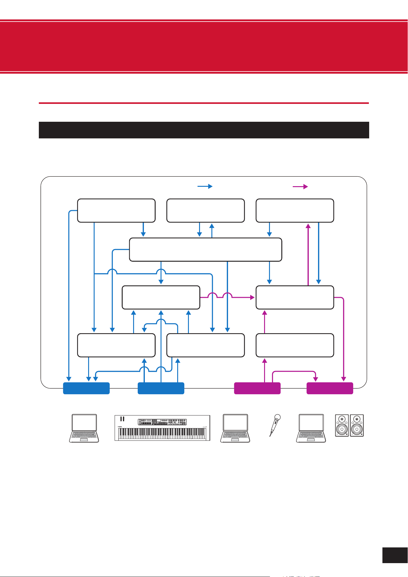
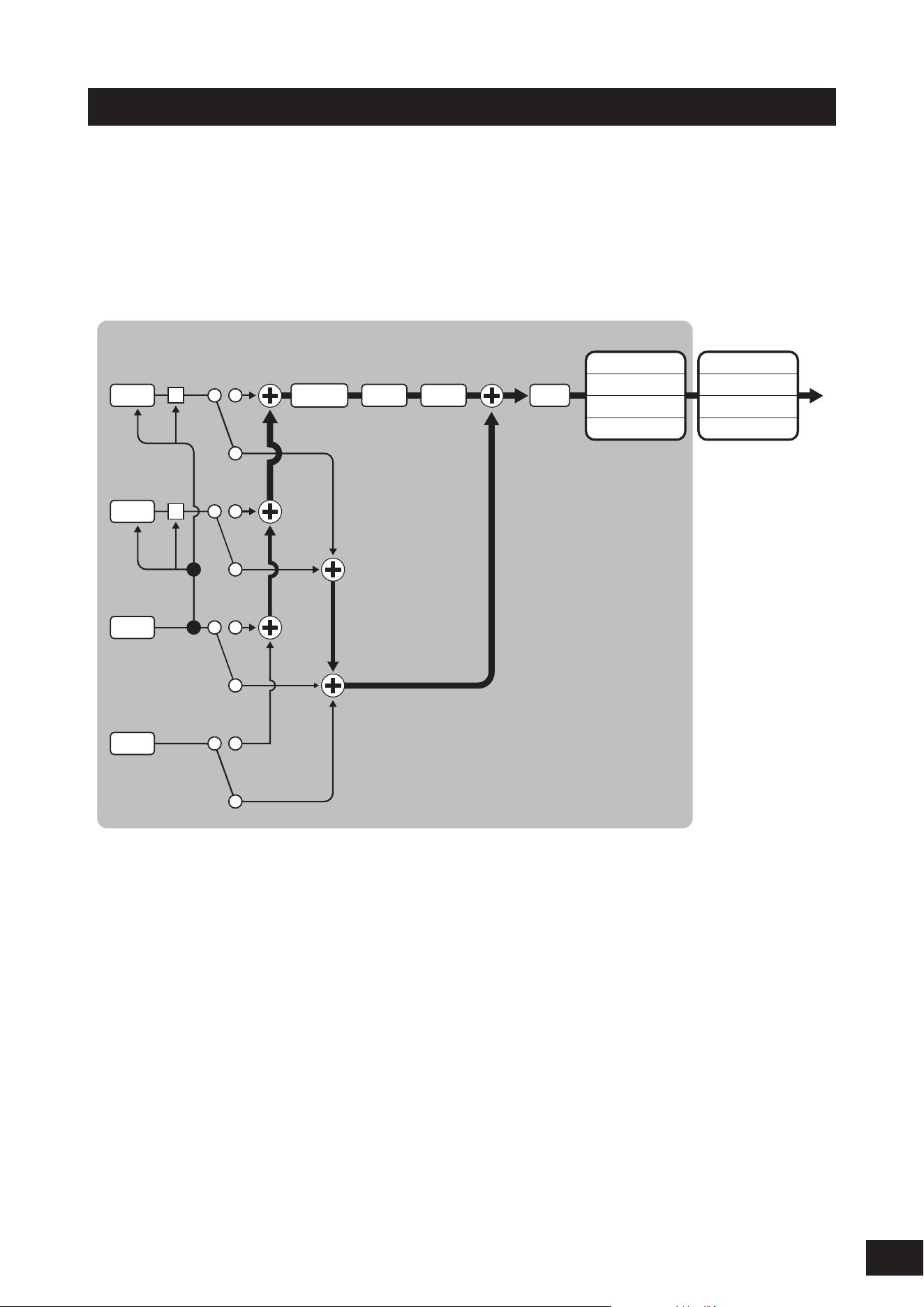
This instrument consists of eight main functional blocks: Controller, Motion Sequencer, Tone Generator, Effects,
Sequencer, Arpeggio, Envelope Follower, and A/D Input.
(1) Control message
(2) Audio signal
(3) Controller
(4) Motion Sequencer
(5) Tone Generator
(6) Effects
(7) Sequencer
(8) Arpeggio
(9) Envelope Follower
(10) A/D Input
(11) Control Matrix
(12) Computer
(13) External MIDI equipment
(14) Microphone, audio equipment,
etc.
(15) Powered speakers, etc.
(1) Control message (2) Audio signal
MIDI IN
AUDIO IN
AUDIO OUTMIDI OUT
USB
[
TO HOST
]
MIDI
[
OUT
]
USB
[
TO HOST
]
MIDI
[
IN
]
USB
[
TO DEVICE
]
USB
[
TO HOST
]
A/D INPUT
[
L/MONO
]
,
[
R
]
USB
[
TO HOST
]
OUTPUT
[
L/MONO
]
,
[
R
]
(12) Computer
(12) Computer
(14) Microphone,
Audio equipment,
etc.
(12) Computer
(15) Powerd
speakers,
etc.
(13) Extermal MIDI equipment
(3) Controller
Keyboard, Knobs, Pedals, etc.
(4) Motion Sequencer
(11) Controll Matrix
(9) Envelope Follower
(8) Arpeggio(7) Sequencer (10) A/D Input
(6) Effects(5) Tone Generator
5
MODX M Operation Manual
Tone generator block
The tone generator block is equipped with a hybrid sound engine combining three synthesis systems.
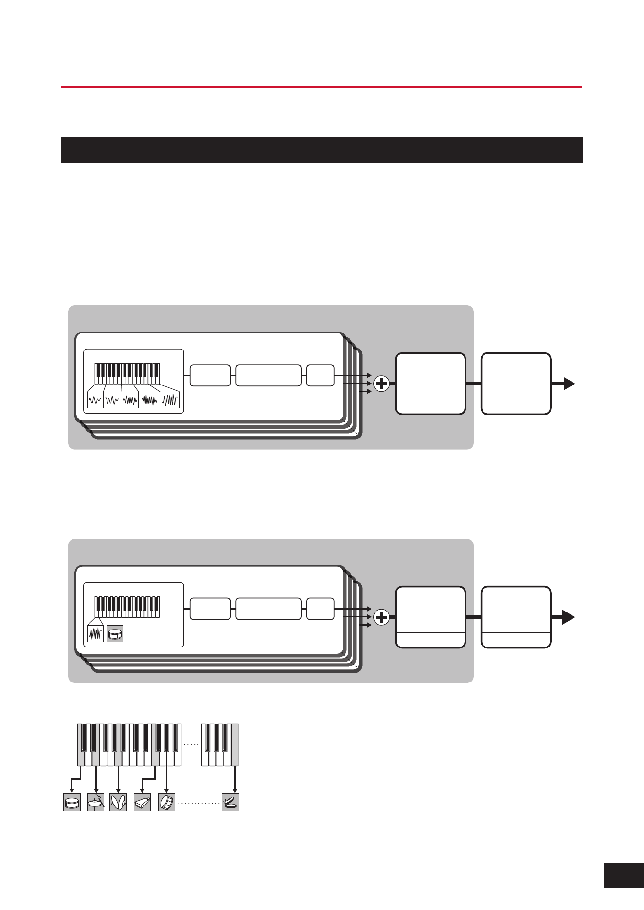
AWM2 sound engine
The AWM2 sound engine features waveforms containing sampled wave data you can assign to each element, and then
modify the sound by using Filters and EGs (envelope generators).
Normal Part
The Normal Part uses up to 128 elements to generate a wide range of rich sounds that help you create expressive
sounds. The "raw" waveforms sampled from acoustic instruments are processed to be compatible with various different
types of music, enabling the realistic reproduction of piano, wind instruments, and so on. You can also try creating new
sounds using functions such as Filters and EGs.
Filter EQAmplitude
Waveform
2-Band EQ
3-Band EQ
Insertion A
Insertion B
Master EQ
Master FX
Reverb
Variation
Element
Part
× 128
Drum Part
For the Drum Part, you can use up to 73 drum keys to assign the waveforms of percussion sounds to each key on the
keyboard to create a desired drum kit.
Key (C0-C6)
Part
× 73
Filter EQAmplitude
Waveform
2-Band EQ
3-Band EQ
Insertion A
Insertion B
Master EQ
Master FX
Reverb
Variation
Individual drum sounds (different for each key) (C0 to C6)
C0
F1 C6
6
MODX M Operation Manual
FM-X sound engine
The FM-X sound engine produces sounds with complex harmonics by frequency modulating (FM) eight waveform
generators called "operators."
The arrangement of the eight operators is called an "algorithm," and there are 88 different patterns available. An operator
has two roles: "carrier" and "modulator."
A modulator modulates the operator it is connected to, and sound is ultimately output from the carrier. It also has a
"feedback" function that allows the operator to modulate the sound itself.
The harmonic structure of the operator's waveform can also be controlled with parameters, allowing you to apply the same
high-quality filters, effects, EQ, etc. as the AWM2 sound engine to create expressive sounds that are difficult to create with
conventional FM sound engines.
2-Band EQ
3-Band EQ
Insertion A
Insertion B
Master EQ
Master FX
Reverb
Variation
Part
(6) Algorithm
(2) Modulators
(3) Carriers
3
4
5
Filter Amplitude
(1) Feedback(1) Feedback
(7)
(8)
(9)
7
1 82 6
(4) Operators
(5) Frequency
modulation
(1) Feedback
(2) Modulator
(3) Carrier
(4) Operator
(5) Frequency Modulation
(6) Algorithm
(7) Modulator wave
(8) Carrier wave
(9) Modulated wave
7
MODX M Operation Manual
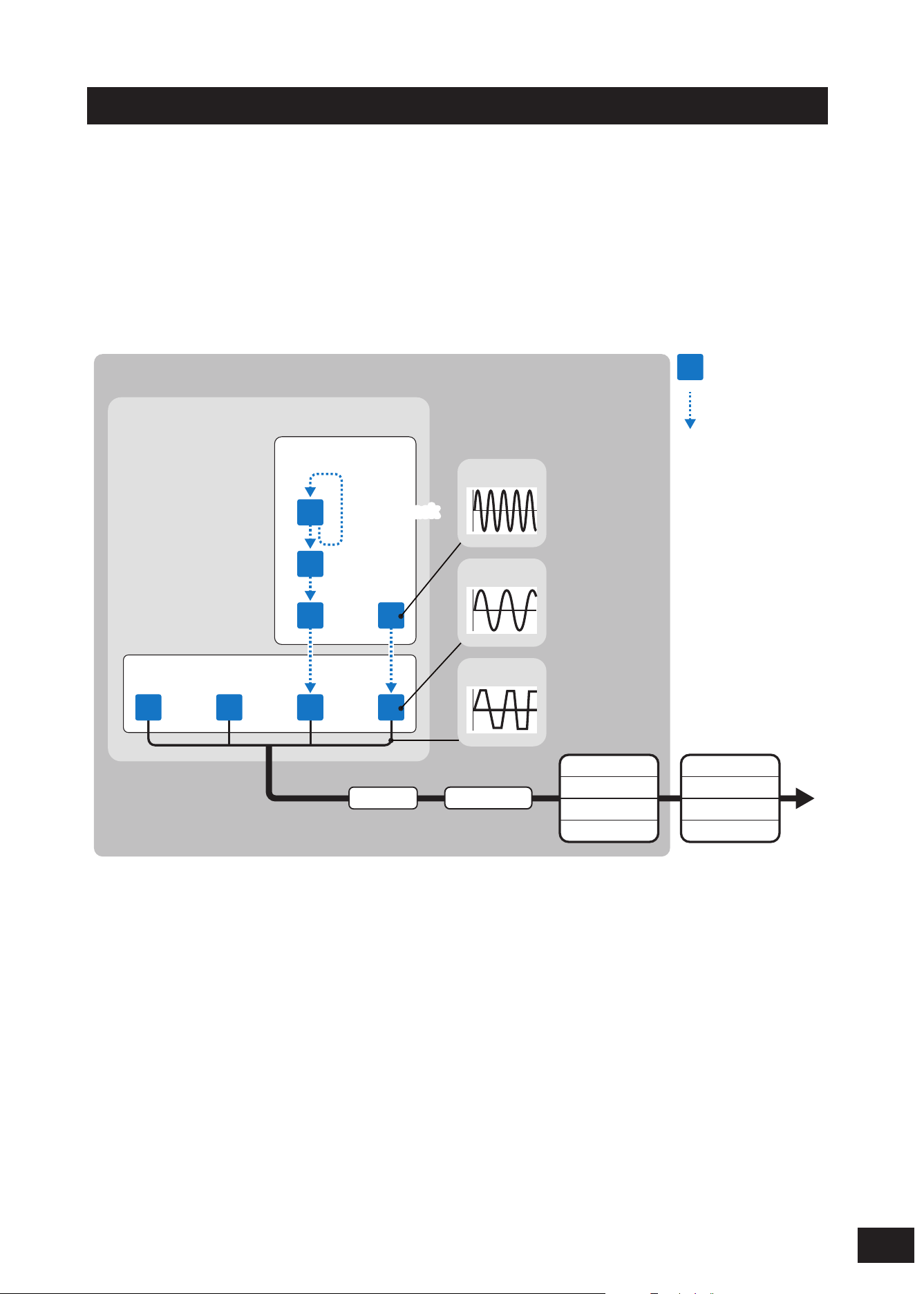
AN-X sound engine
The AN-X sound engine is a virtual analog sound engine that fully digitally reproduces the behavior and characteristics
of analog synthesizers. It is a new-generation AN sound engine that combines elements of tradition and innovation, and
can express a wide range of sounds from realistic vintage sounds to edgy, extreme sounds.
The AN-X sound engine consists of three oscillators and one noise generator. Each oscillator is equipped with waveform
control functions such as Pulse Width, OSC Self Sync, and Wave Shaper, allowing for great freedom in sound creation.
In addition, Oscillator 3 (OSC 3) can modulate Oscillator 1 (OSC 1) and Oscillator 2 (OSC 2) using FM or ring modulation,
and the output destination of each oscillator can be set to before or after Filter1 or Filter2.
2-Band EQ
3-Band EQ
Insertion A
Insertion B
Master EQ
Master FX
Reverb
Variation
Part
FM Ring
Mod
Ring
Mod
FM
Modifier Filter1 Filter2 AmpOSC 1
OSC 2
OSC 3
Noise
8
MODX M Operation Manual
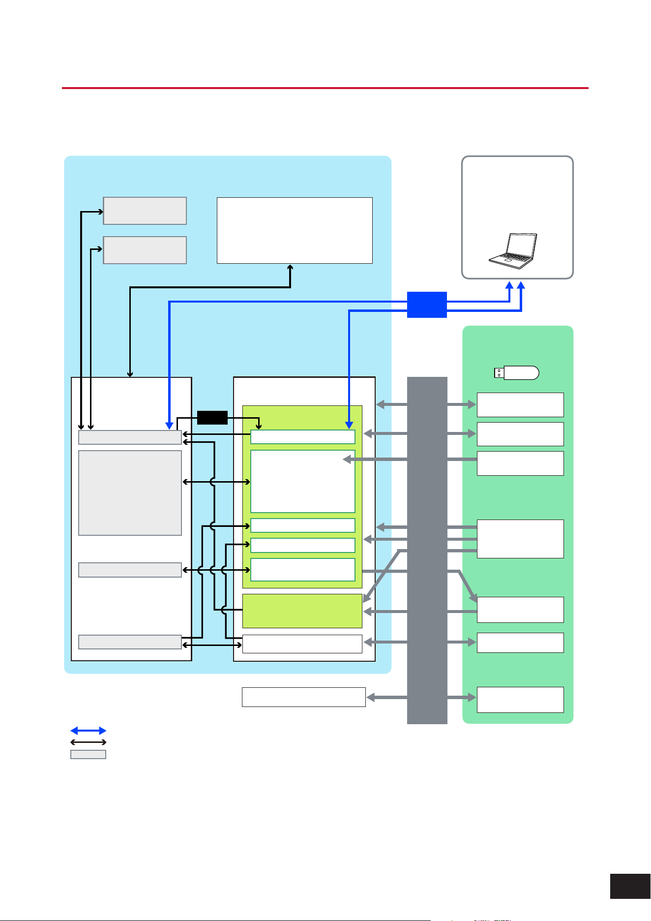
Internal memory
The internal memory of this instrument holds the saved Performances, Live Sets, Songs, and other settings.
This chart shows the data flow between the internal memory and the external device.
Data communication with external devices
Internal data communication
Temporary storage area (erased when power is turned off)
• User waveform edit
• User motion sequence edit
• User curve edit
• User micro tuning edit
• User live set edit
• Performance
• Arpeggios
• Motion sequence
• Audition phrases
• User waveforms
• User motion sequences
• User curves
• User micro tuning
• User live sets
• User audition phrases
• Waveforms
• Live sets
• Curves
• Micro tuning
MIDI device or
computer
DAW software
MONTAGE and other
compatible files
(.X7A, .X7U, .X7L, etc.)
Library area
*Same as user area
(Excluding utility settings and quick setup)
• User arpeggios
• Utility settings
• Quick setup
• User performance
Audio files
(.WAV)
Audio record play
Audio files
(.WAV and .AIF)
User files
(.Y2U)
Backup files
(.Y2 A)
Library files
(.Y2 L)
MIDI files (.MID)
Pattern / song area
User area
User memory
Bulk
dump
Save
Load
USB flash drive
Store
Preset memory
Compare buffer
(Performance)
Recall buffer
(Performance)
• Pattern / song record
• Utility settings
• Performance edit
Edit buffer
MODX M internal memory

9
MODX M Operation Manual
Preset memory
Contains the Preset Performances, Preset Arpeggios, Preset Audition Phrases, and other settings. You cannot overwrite
the data in the Preset memory since it is read-only.
Edit buffer
The Edit buffer is the work area for editing Performances, Live Sets, Songs, and other settings.
This work area allows both reading and writing, and the contents within this work area are erased when the instrument is
turned off.
Edited data must be saved to User memory before switching Performances or turning the instrument off (however, data
other than Performances and Motion Sequences is saved automatically).
User memory
The User memory has two areas: User and Library.
User area
The User area holds the stored Performances and Motion Sequences, and other settings for the entire instrument, such
as Utility settings and other User data edited in the Edit buffer.
When a User Performance is edited, you can store it as a new Performance or overwrite the existing Performance.
Library area
The Library area allows up to 24 library files (.Y2L) to be loaded from the USB flash drive. The settings saved in the Library
area cannot be edited. To edit the settings in the Library area, send the data to the Edit buffer by selecting a Performance
stored in the Library area or loading a Motion Sequence from the Library area. After editing, the data will be stored in the
User area.
The User memory is used for reading and writing, and the data within this area will be retained after the instrument is
turned off.
Recall buffer and Compare buffer
The Recall buffer and Compare buffer are areas used for temporarily saving the settings you are editing.
Recall buffer
The Recall buffer is used as a backup for the Edit buffer.
If you accidentally changed to a different Performance without first storing the setting, you can use the Recall function to
restore the temporarily saved settings from the Recall buffer to the Edit buffer.
Compare buffer
The Compare buffer is the area for keeping settings before making edits. By using the Compare function, you can bring
the settings temporarily saved in the Compare buffer to compare the edited and unedited sounds.
These buffers are for reading and writing data, but the settings will be lost when the instrument is turned off.

10
MODX M Operation Manual
2. Setting up for Live Performance
Shown below is a general workow guide for this instrument.
Selecting a Performance
Select from the Live Set screen or from the Performance screen (Category Search screen).
Editing the settings
Saving edited settings
Creating a Live Set
Selecting a Live Set
Playing the Keyboard
11
MODX M Operation Manual
Selecting a Performance
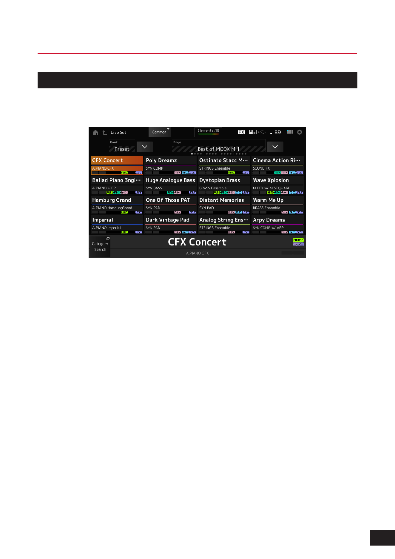
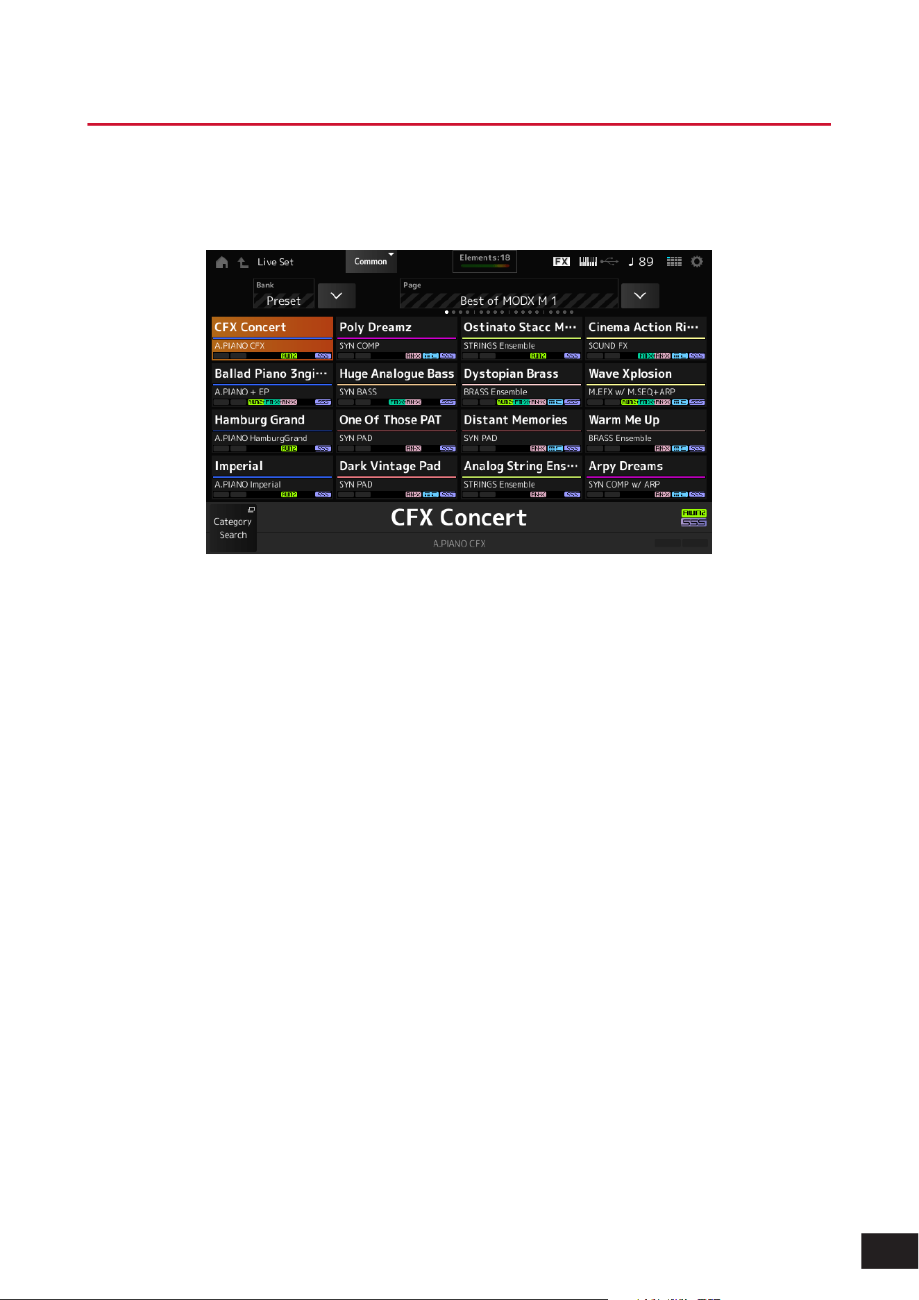
Selecting on the Live Set screen
1.
Press the [LIVE SET] button.
The Live Set screen will open.
2.
Tap to select the Performance you want from the displayed list.
12
MODX M Operation Manual
Selecting on the Category Search screen
The Category Search function allows you to search through Performances, Parts, Rhythm Patterns, Arpeggios, and
Waveforms to nd ones you would like to use. To search for a Performance, press the [CATEGORY] button with the
Performance screen open to open the Performance Category Search screen.
Even while the Category Search screen is displayed, you can switch parts and mute using the buttons on the top panel.
NOTE
You can also select a Performance by moving the cursor to the Performance name on the Home screen and using the Data dial, [INC/
YES] button, or [DEC/NO] button.
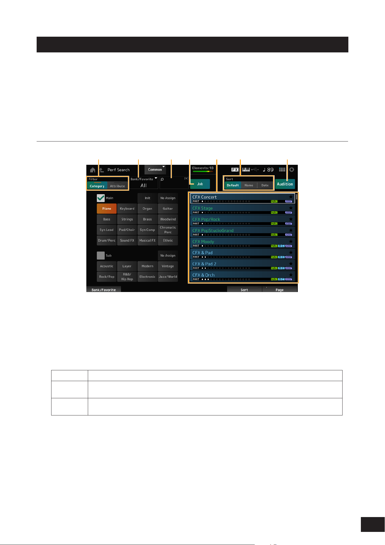
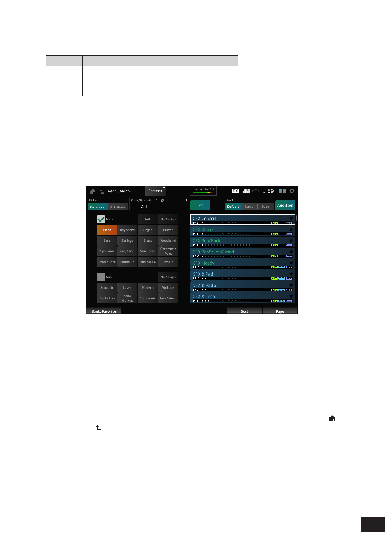
Screen description
(1) (2) (3) (4) (6)(5) (7)
(1) Filter
You can use the lter to search through the list of Performances.
• Category
You can select one each from Main and Sub.
• Attribute
Select an attribute or combinations of attributes. The lter will vary depending on the combination.
Filter:
Exact match
AWM2, FM-X, AN-X
AND
condition
MC, SSS, Smart Morph
OR condition Single, Multi
MOTIF XF, MONTAGE, MODX M OS Vx.x (x.x is the OS version number)
NOTE
“MONTAGE” includes MODX and MODX+.
(2) Bank
(3) Search by keyword
(4) Job
13
MODX M Operation Manual
(5) List of Performances
The Performances that correspond to the selected Category and Attribute are displayed.
Text color Description
White Currently selected Performance
Green Single-Part Performance
Blue Multi-Part Performance
(6) Changing the sort order
(7) Audition
Procedure
1.
Press the [CATEGORY] button.
The Performance Category Search screen appears.
This screen can also be opened by selecting Category Search from the context menu for the Performance Name.
2.
Use the filter as needed.
Search the Performances by switching lters, banks, and sorting.
3.
Select from the list.
Select from the list of Performances displayed on the right side of the screen.
Use the Data dial, [INC/YES] button, [DEC/NO] button, or up and down buttons to make your selection.
You can also use the Display knob to scroll through the screen without changing the currently selected
Performance.
4.
Close the screen.
Press the [ENTER] button, [EXIT] button or [PERFORMANCE (HOME)] button on the top panel, or tap the [ ]
(HOME) icon or [
] (EXIT) icon on the screen.
NOTE
You can use the Part Category Search function if you wish to change one of the Parts in a Multi-Part Performance (a Performance that
has more than one Part). Select the Part you wish to change, then press the [CATEGORY] button while holding down the [SHIFT] button
to display the Part Category Search screen.

14
MODX M Operation Manual
Selecting an Initialized Performance or a Single-Part Performance
Initialized Performance
Set Bank/Favorite to either All or Preset.
Set the lter to Category and select Init.
Single-Part Performance
Set the lter to Attribute and select Single.

15
MODX M Operation Manual
Playing back an audition phrase
By playing back the audition phrase, you can check the Performance. You can also hear how the sound of the
Performance changes by manipulating the controller during playback.
1.
Press the [AUDITION] button on the top panel or tap Audition on the Category Search screen.
The Audition phrase of the current Performance will be played back.
If you switch Performances during playback, the phrase from the new Performance will be played back.
NOTE
If the [AUDITION] button is turned off, the audition function is not available for the selected Performance, and nothing happens
when you press it.
2.
To stop the playback of the audition phrase, press the [AUDITION] button on the top panel once
more, or tap the Audition button on the Category Search screen.
16
MODX M Operation Manual
Using overall functions for the entire Performance
There are other functions for adjusting the balance between Parts within the Performance or for quickly switching to
different groups of settings that have been registered to the buttons in advance.
Mixing
The Mixing function allows you to adjust the balance between Parts.
You can check the settings for each Part, such as Pan, Volume, and EQ, and adjust the parameters.
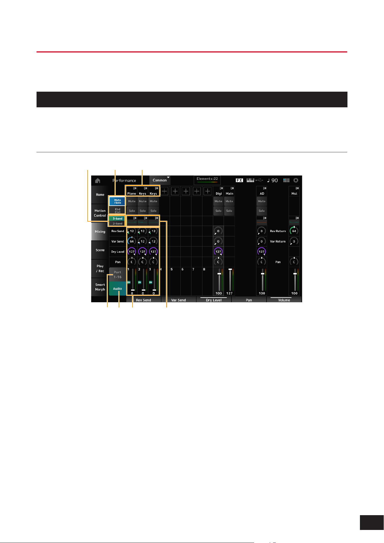
Screen description
(1)(2)(3)
(4)(7) (5)(6)
(1) Main category for each Part
(2) Switching views for Solo, Mute, and Kbd Ctrl
(3) Switching between 3-band EQ and 2-band EQ
(4) EQ settings for each Part
(5) Parameters for each Part
(6) Switching to 16-part view
(7) Switching to Audio Part view (Parts 9 to 16 hidden)
You can set the following audio parameters for an
Audio Part.
• AD part: Audio input from the A/D INPUT jacks
• Digital part: Audio input from the USB [TO HOST]
terminal
* Refers to the audio set to Digital L/R in audio channels

17
MODX M Operation Manual
Procedure
1.
Press the [PERFORMANCE (HOME)] button and tap Mixing.
The Mixing screen appears.
2.
Select a Parameter.
Select a Parameter by using the PART buttons or cursor buttons, or tap the icons and buttons on the screen.
3.
Change the value by using the Data dial or relevant Display knob.
NOTE
If you need to fine-adjust the value, press the [EDIT/ ] button while the Mixing screen is shown on the display to open the Edit screen.
18
MODX M Operation Manual
Scene
The Scene is a “snapshot” of various settings, such as Arpeggio type, Motion Sequence type, and Part parameters.
By registering different Scenes to each of the eight SCENE buttons, you can use the SCENE buttons to recall different
settings instantly.
This would be convenient, for example, when you wish to change only the Arpeggio and Motion Sequence types, without
changing the Performance, to follow the progression of a song, or to bring out a different aspect of a Performance.
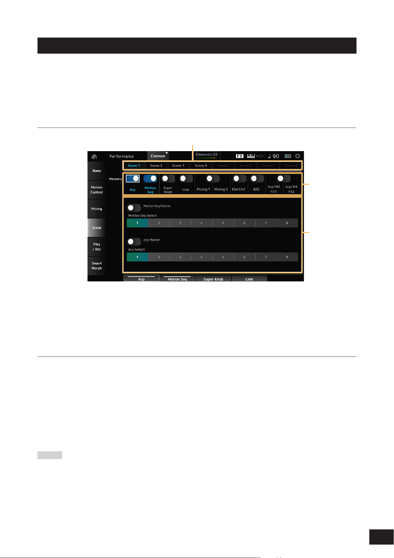
Screen description
(1)
(2)
(3)
(1) Scene tab
(2) Memorize switch
(3) Settings for the tab
When the Memorize switch is On, the parameters for the function appear on the screen.
Procedure
1.
Press the [PERFORMANCE (HOME)] button and tap Scene.
The Scene screen appears.
2.
Set up Scene 1
–
8.
The functions to which Memorize Switch (Memory) has been set to On will be registered to the selected SCENE
button.
The newly set Scene now becomes active when you press the appropriate SCENE button.
3.
Press the [STORE] button to save the Performance.
NOTICE
Make sure to save (store) the Scene settings you have just edited before changing to a different Performance or turning off the
instrument. Without performing the Store operation, the Scene settings will be lost.
NOTE
If a Parameter that can be registered to the SCENE button has already been assigned to a knob or slider, operate that. You can then
register the settings to a button by holding down the [SHIFT] button and pressing one of the SCENE buttons.
After that, press the [STORE] button to save the Scene settings to the Performance.
19
MODX M Operation Manual
Editing the settings
Using Split and Layer
What is Split?
This setting divides the entire keyboard into multiple groups and assigns a Part to each group. On this instrument, you
can specify the split point and set the key range for each group.
What is Layer?
This setting allow you to combine multiple Parts on top of each other and play them simultaneously. By assigning two or
more Parts to the same group, you can play a combination of multiple tones.
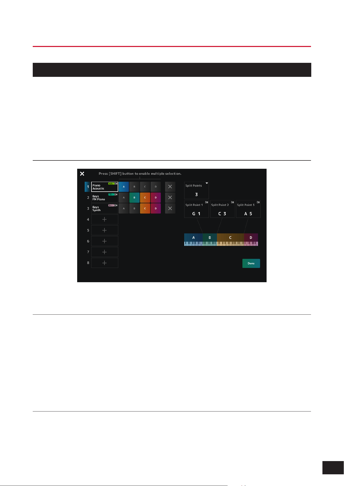
Split Job Screen
For a description of each item on the screen, refer to Split Job.
Split setting procedure
1.
Press the [SPLIT] button.
The Split Job screen for the Performance appears.
2.
By tapping the items on the screen to specify the number and position for the Split Point, you can
set the key range for each group.
Tap the group buttons while holding down the [SHIFT] button to assign a single Part to multiple groups.
3.
Press the [EXIT] button or tap Done on the screen to confirm the settings.
Tapping [×] (Close) on the upper left cancels the setup.
Note range setting procedure
1.
Hold down the [SHIFT] button and press the [SPLIT] button.
The Part - Note view is shown on the Performance screen.
2.
Use the keyboard or Data dial to change the note range for each Part.
20
MODX M Operation Manual
Procedure for editing
1.
Select a Performance.
2.
On the Performance screen, move the cursor to the desired Performance name or Part you want
to edit.
3.
Press the [EDIT/ ] button or tap Edit in the context menu.
The Common Edit screen will appear when the cursor is on the Performance name.
The Part Edit screen for the sound engine will appear when the cursor is on the Part.
NOTE
You can change the Parameter to be edited by opening the Common Edit screen on the Edit screen and selecting the desired item
from the Navigation bar.
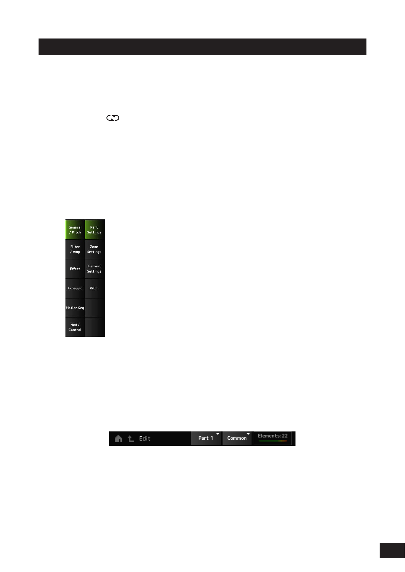
4.
Select a tab on the first and the second rows to open the screen.
Changing the settings in each tab from the top to the bottom is recommended.
Example: Normal Part (AWM2)
5.
Edit the settings by changing the parameters shown on the right of the tabs.
6.
Continue editing the parameters on different tabs if necessary.
The target for editing will be shown on the navigation bar.
Select Common for editing the settings for the entire Performance.
Select Part Common for editing the settings for the entire Part.
If you wish to go into detailed settings, select one of the following: Element 1–128, Operator 1–8, Oscillator 1–3,
Noise, and C0–C6.
7.
When you’ve finished editing, press the [STORE] button to save the Performance.
21
MODX M Operation Manual
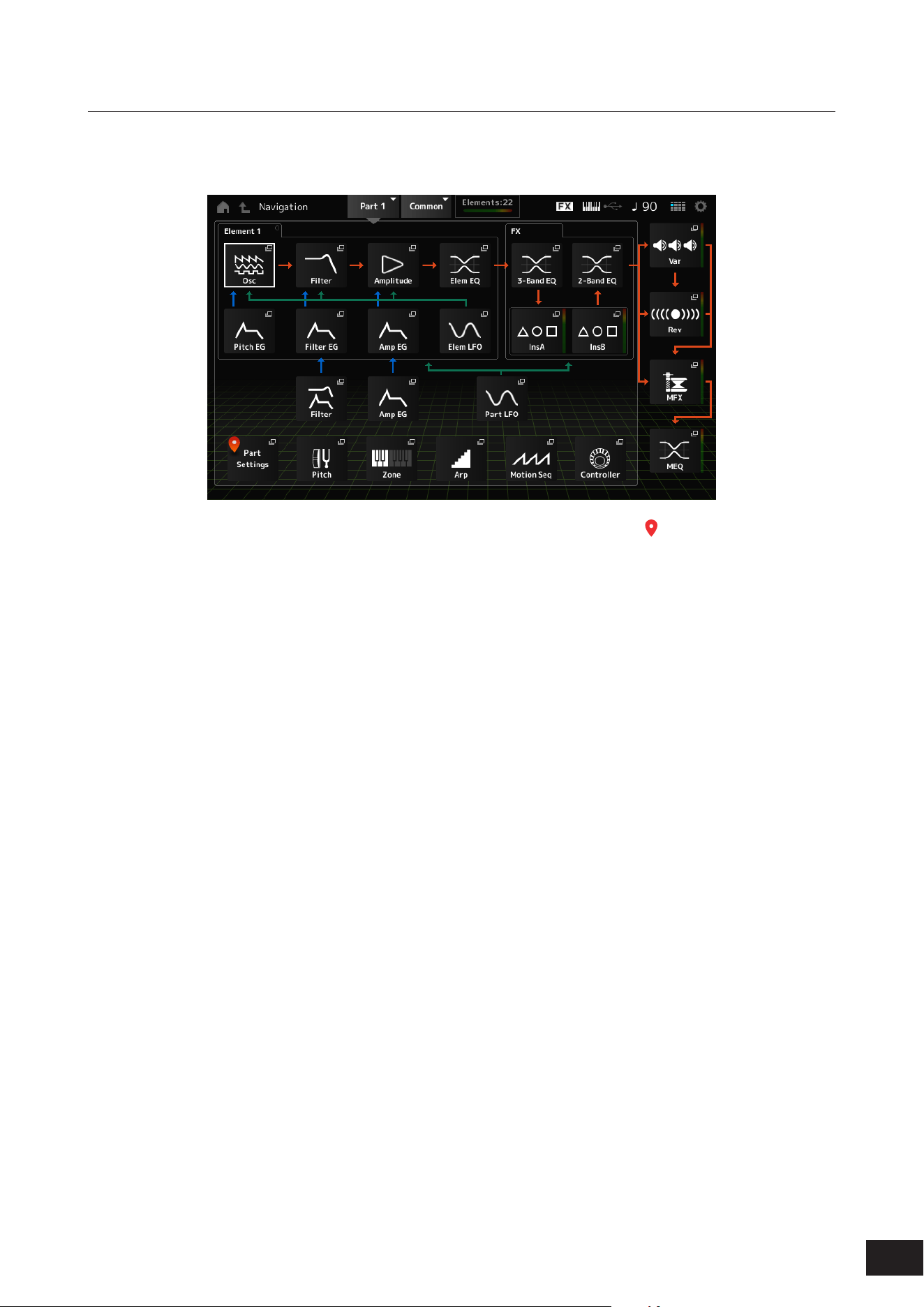
Using the Navigation screen
1.
Press the [NAVIGATION] button.
The NAVIGATION screen appears.
Pressing the [NAVIGATION] button during editing calls up the current location icon (
).
2.
Select the item for editing.
Select Part Common for editing the settings for the entire Part.
If you wish to go into detailed settings, select one of the following: Element 1–128, Operator 1–8, Oscillator 1–3,
Noise, and C0–C6.
3.
Select the icon for the Parameter you want to edit.
Use the cursor buttons to move the cursor, and press the [ENTER] button. Or, tap the icon on the screen.
4.
Select the icon for the setting you want to edit.
5.
Change the parameters shown on the screen.
6.
Save the Performance.
22
MODX M Operation Manual
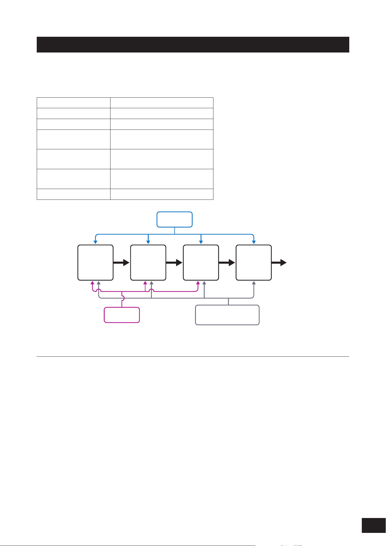
Creating tonal changes
For creating tonal changes, you can use Oscillators, filters, EGs (or Envelope Generators), LFOs (or Low-Frequency
Oscillators), and effects. By changing those parameters, you can change the brightness, resonance, or other timbral
qualities of the sound.
The detailed settings vary depending on the sound engine, but the common settings are as follows:
Oscillators (Osc) Creates a waveform
Pitch (Pitch) Controls the pitch
Filters (Filter) Controls the cutoff frequency
EG Determines how the sound changes
over time
LFO Determines the cyclical change of the
sound
Motion Sequencer Creates complex changes to the
sound over time
Effects (Effects) Processes the sound
LFO
EG
Motion Sequencer
Envelope Follower
Osc
(Oscillator)
Filter Amp Effects Output
Effect configuration
System Effect
This effect is applied to all Parts of the Performance.
The System Effect include two types: Variation and Reverb. You can also add Reverb to the Variation's output sound
(Variation to Reverb).
Insertion Effect
This effect is applied to each Part.
Master Effect
This effect is applied to the overall sound at the final output.
Part EQ
A 3-band and 2-band equalizer that is applied to each Part.
The Part EQ can be applied before or after the Insertion Effect.
Master EQ
A 5-band equalizer that is applied to the overall sound at the final output.
23
MODX M Operation Manual
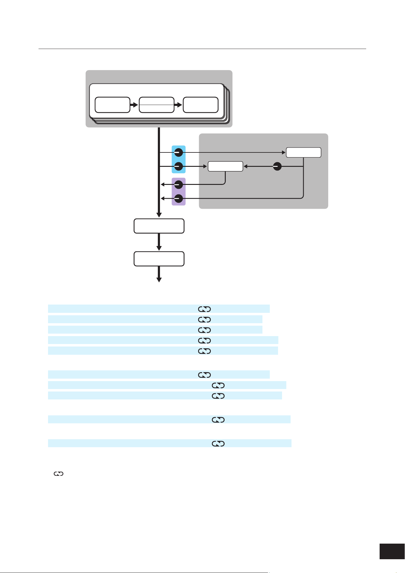
Effect connections and settings
Connect as shown in the diagram below and set up each one using methods (1) to (4).
Part
Insertion A
Insertion B
Part EQ
3-Band EQ
Part EQ
2-Band EQ
Performance
(
1
)
(
2
)
(
3
)
(
4
)
System Effect
Master Effect
Master EQ
Reverb
Variation
Variation to Reverb
Send Level
Return Level
(1) Setting the Part EQ and Insertion Effect
[PERFORMANCE (HOME)]
→
Part selection
→
[EDIT/
]
→
Effect
→
Routing
[PERFORMANCE (HOME)]
→
Part selection
→
[EDIT/
]
→
Effect
→
Ins A
[PERFORMANCE (HOME)]
→
Part selection
→
[EDIT/
]
→
Effect
→
Ins B
[PERFORMANCE (HOME)]
→
Part selection
→
[EDIT/
]
→
Effect
→
3-band EQ
[PERFORMANCE (HOME)]
→
Part selection
→
[EDIT/
]
→
Effect
→
2-band EQ
(2) Setting the Variation and Reverb
[PERFORMANCE (HOME)]
→
Part selection
→
[EDIT/
]
→
Effect
→
Routing
[PERFORMANCE (HOME)]
→
Common selection
→
[EDIT/
]
→
Effect
→
Variation
[PERFORMANCE (HOME)]
→
Common selection
→
[EDIT/
]
→
Effect
→
Reverb
(3) Setting the Master Effect
[PERFORMANCE (HOME)]
→
Common selection
→
[EDIT/
]
→
Effect
→
Master FX
(4) Setting the Master EQ
[PERFORMANCE (HOME)]
→
Common selection
→
[EDIT/
]
→
Effect
→
Master EQ
NOTE
Set the effect for the audio input signal from the A/D INPUT jacks as follows: [PERFORMANCE (HOME)]
→
Common selection
→
[EDIT/ ]
→
Audio In.
For information on the effect category and effect types, refer to the Effect types. For information on the effect parameters,
refer to the Effect parameters.
For information on the Preset program for each effect type, refer to the Data List.
24
MODX M Operation Manual
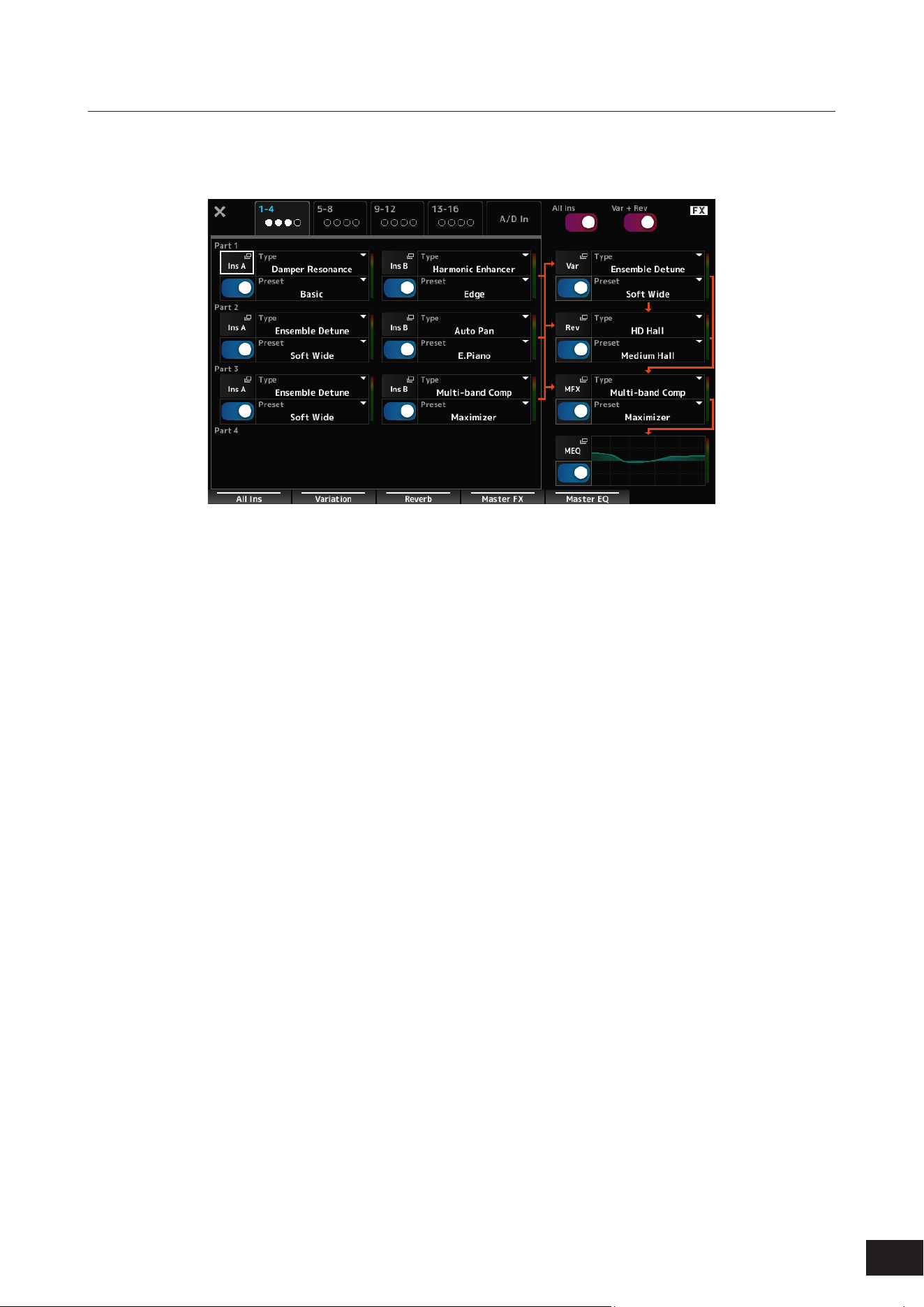
Changing the Effect settings
By pressing the [NAVIGATION] button while holding down the [SHIFT] button, the FX Overview screen will appear, and
you can see an overview of the effect settings. Tap the buttons on the effect names such as Ins A and Var to open the Edit
screen.
25
MODX M Operation Manual
Using Arpeggio
Arpeggio is a function that automatically plays rhythm patterns and chord backings simply by pressing keys.
It not only provides inspiration and full rhythmic passages in your live performances, but it gives you fully formed
instrumental backing parts of various music genres for ease in creating songs.
Features of the Arpeggio function of this instrument
This instrument allows you to set up to eight Arpeggio types for each Part, and play back Arpeggios for eight Parts
simultaneously.
You can also set the range of keys used for Arpeggio playback (Note Limit) and the upper and lower limits of key pressure
(Velocity Limit).
The Arpeggio function lets you play Accent Phrases (the sequence phrase played only when the keyboard is played at a
higher velocity than the specified value) or effect sounds such as guitar fret noises using the Random SFX function.
You can search for preset Arpeggios containing these sounds on the Arp Category Search screen. Specifying Accent
(Accent Phrase) or Random SFX in Attribute will narrow down the Arpeggios that match.
Turning Arpeggio on and off
To turn the Arpeggio function on or off, press the [ARP] button on the top panel.
Changing Arpeggio by using the knobs
Select ARP/MSEQ with the [QUICK EDIT] button and use Knobs 1 and 2 to change the way the Arpeggio sounds.
Modify the sound by turning the knobs and listening to the Arpeggio playback.
For details on the effects of Knobs 1 and 2, refer to Arp/MS
→
Arp Common on the Common Edit screen.
Changing the way Arpeggio playback is turned on or off
You can freely change the Arpeggio playback method from a setting that plays only while you hold down the key to a
setting that continues playing even after you lift your finger from the key, etc. Follow the steps below to change this setting:
Hold
[EDIT/ ] button
→
Part selection
→
Common
→
Arpeggio
→
Common
Trigger Mode
[EDIT/ ] button
→
Part selection
→
Common
→
Arpeggio
→
Advanced
Setting Hold Trigger Mode
Played back only while a key is being pressed Off Gate
Playback continues after the finger is lifted off from the key On Gate
Playback is turned on or off each time the key is pressed Regardless of
whether On/Off
Toggle
NOTE
When Arp Master and Arp Part are on, turn the [KEYBOARD HOLD] button on the top panel on to achieve the same effect as when Hold
is On.
26
MODX M Operation Manual
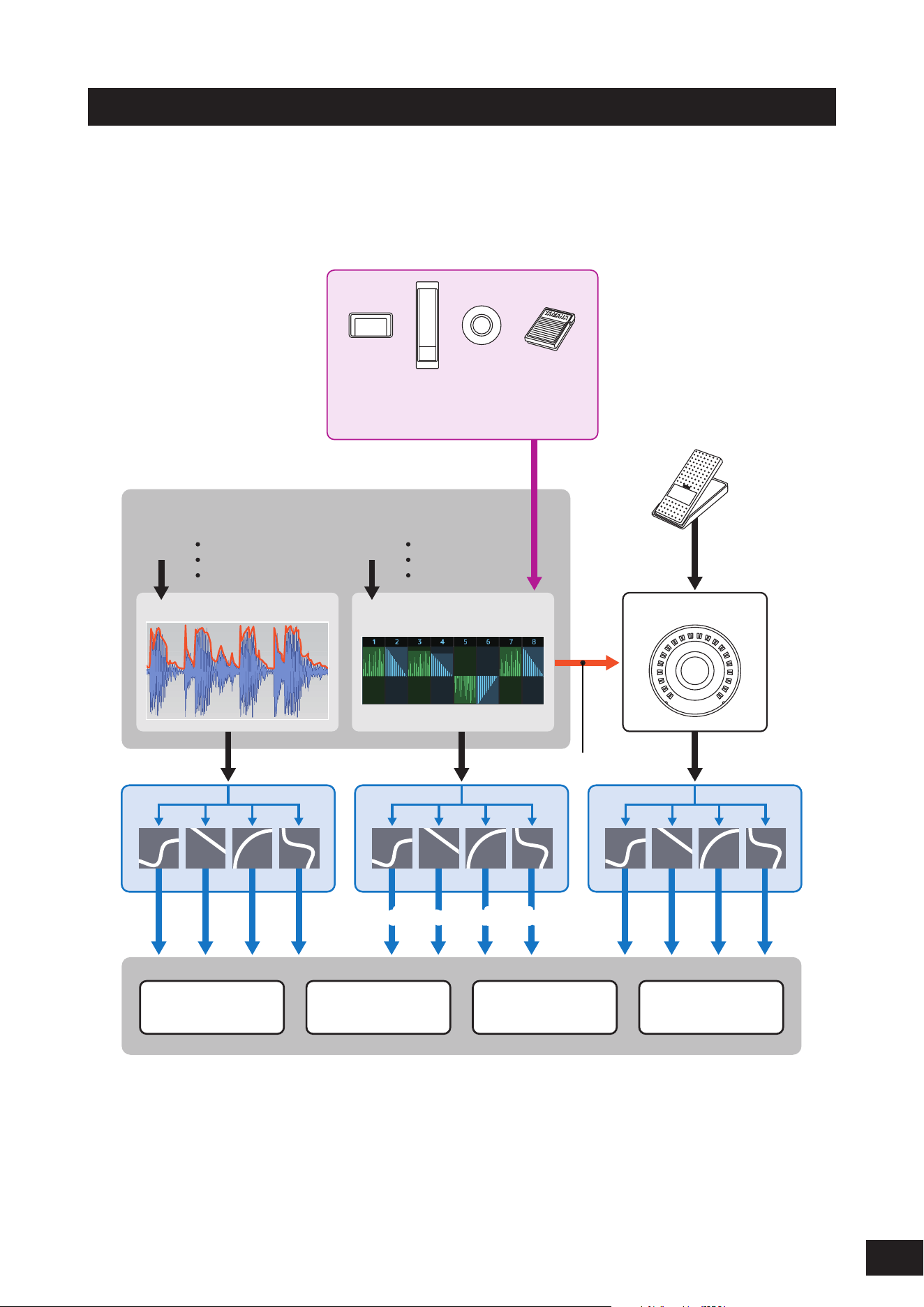
Using Motion Control
The Motion Control function lets you create Motion (rhythmic and dynamic sound changes) in real time, so you can find
completely new ways of expression.
This function allows you to make the settings in advance so that you can change the parameters without actually
operating the pedals or wheels.
This lets you create dramatic and powerful expressive changes that follow the beat of your music.
(
1
) Continuous control of Motion changes
(
2
) Switch between Motions
(
3
) Trigger
Motion SequencerEnvelope Follower Super Knob
Beat
Audio Beat Sync
External MIDI
Internal Tempo
Audio
Part 1-16
A/D Input Part
Master
Tone Generator Effect Arpeggio Motion Sequencer
(
5
) Rhythmic change
(4) Control the Motion Sequencer in real time
(6) Automation
(
7
) Multi-dimensional sonic change(
7
) Multi-dimensional sonic change
(1) Continuous control of Motion changes
(2) Switch between Motions
(3) Trigger
(4)
Control the Motion Sequencer in real time
(5) Rhythmic change
(6) Automation
(7) Multi-dimensional sonic change
27
MODX M Operation Manual
Setting Motion Control
Motion Control can be set by setting the Source for the Controller as well as the Destination and Parameter from the
Control Assign screen.
How to open the Control Assign screen
[PERFORMANCE (HOME)]
→
Tap Common
→
[EDIT/ ]
→
Control
→
Control Assign
[PERFORMANCE (HOME)]
→
Select Part
→
[EDIT/
]
→
Mod/Control
→
Control Assign
Setting to Super Knob
Set the Display Filter to SuperKnob, and select the Source (AsgnKnob 1–8), Destination, etc.
Setting to Motion Sequence
For Motion Sequence, set the Source to a Motion Sequence Lane from 1 to 4.
Setting to Envelope Follower
Set the Source to EnvFollow.
Customizing the Super Knob settings
By using the Super Knob, you can simultaneously control the Assign 1–8 values that are assigned to Knobs 1 to 8 that
are common to all Parts.
By combining the Super Knob and the Motion Sequencer, you can achieve more complex sound changes.
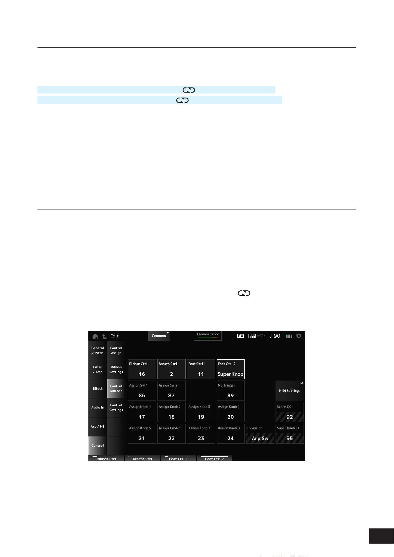
Controlling the Super Knob from the pedals
You can control the Super Knob from the separately sold Foot controller (FC7) connected to this instrument.
1.
Connect the Foot Controller (FC7) to the FOOT CONTROLLER jack ([1] or [2]).
2.
Open the screen from: [PERFORMANCE (HOME)]
→
[EDIT/ ]
→
Control
→
Control Number.
3.
Select SuperKnob for Foot Ctrl1 or Foot Ctrl2, depending on the jack you have connected the
Foot Controller (FC7) to.
4.
Close the screen to finish the setup.
28
MODX M Operation Manual
An example of a Super Knob setting
The Super Knob settings can be customized.
You can set two or three fixed values for using the Super Knob for morphing sounds. With three fixed values, you can set
the median value.
An example of morphing using three fixed values
Here, we will explain how to add morphing effects to the layered sound made with three Preset Performances (acoustic
piano, pad sound, and electric piano). Additionally, we'll explain how to add a morphing effect while keeping the original
settings for these Performances.
MID
LEFT RIGHT
Acoustic Piano
(CFX PopStudioGrand)
Electric Piano
(TV Show FM EP)
Pad sound
(AN-X Sine Pad PAT)
1.
Select sounds for Parts 1 to 3.
1-1.
Press the [CATEGORY] button and select CFX PopStudioGrand.
1-2.
From the Home screen, tap the [+] icon for Part 2 to open the Part Category Search screen and select AN-X Sine
Pad PAT.
1-3.
From the Home screen, tap the [+] icon for Part 3 to open the Part Category Search screen and select TV Show FM
EP.
2.
Set the parameters for Part 1.
2-1.
Select Part 1.
2-2.
Press the [CONTROL ASSIGN] button while holding down the [SHIFT] button to open the Control View screen.
2-3.
Turn the Super Knob to open the Control Assign screen.
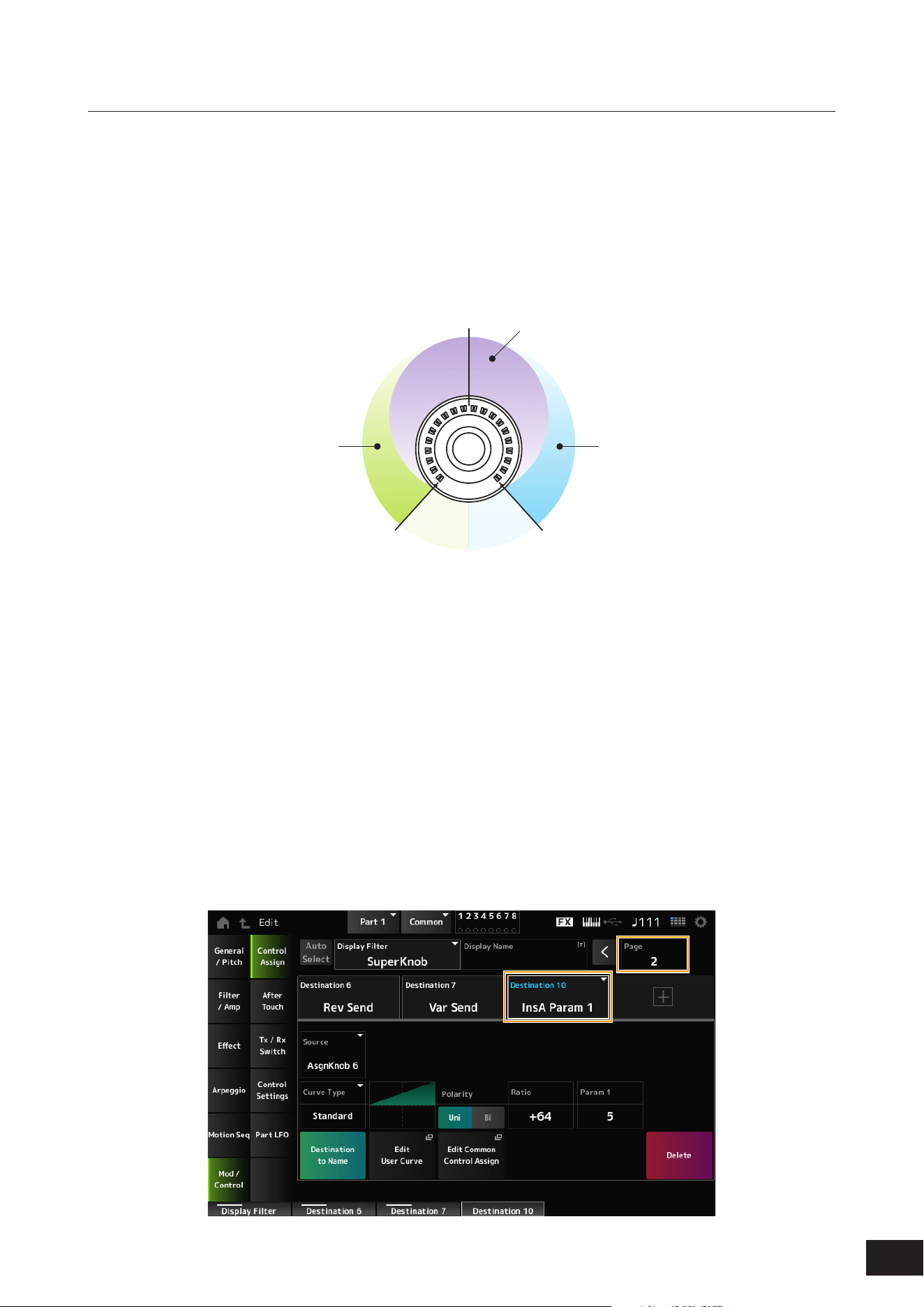
2-4.
Go to Page 2 and tap the [+] icon to add Destination 10.
29
MODX M Operation Manual
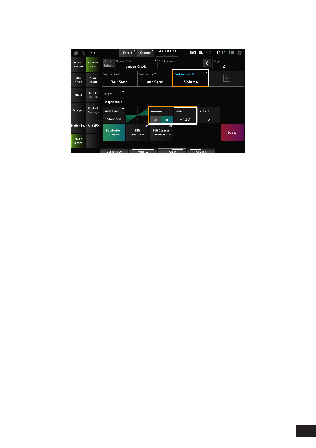
2-5.
Tap the Destination 10 tab and select Volume from Part Param.
2-6.
Set Polarity (Curve Polarity) to Bi and set Ratio (Curve Ratio) to +127.
3.
Set the parameters for Part 2.
3-1.
Select Part 2.
3-2.
Press the [CONTROL ASSIGN] button while holding down the [SHIFT] button and then turn the Super Knob. The
Part 2 Control Assign screen will open.
3-3.
Tap the [+] icon to add Destination 8.
3-4.
Tap the Destination 8 tab and select Volume from Part Param.
3-5.
Set Polarity (Curve Polarity) to Bi and set Ratio (Curve Ratio) to +127.
4.
Set the parameters for Part 3.
4-1.
Select Part 3.
4-2.
Press the [CONTROL ASSIGN] button while holding down the [SHIFT] button and then turn the Super Knob. The
Part 3 Control Assign screen will open.
4-3.
Tap the [+] icon to add Destination 8.
4-4.
Tap the Destination 8 tab and select Volume from Part Param.
4-5.
Set Polarity (Curve Polarity) to Bi and set Ratio (Curve Ratio) to +127.
30
MODX M Operation Manual
5.
Check to make sure that the parameters for Parts 1 to 3 are set to Common Assignable Knob.
5-1.
Press the [COMMON] button.
5-2.
Press the [CONTROL ASSIGN] button while holding down the [SHIFT] button and then turn the Super Knob. The
Common Control Assign screen will open.
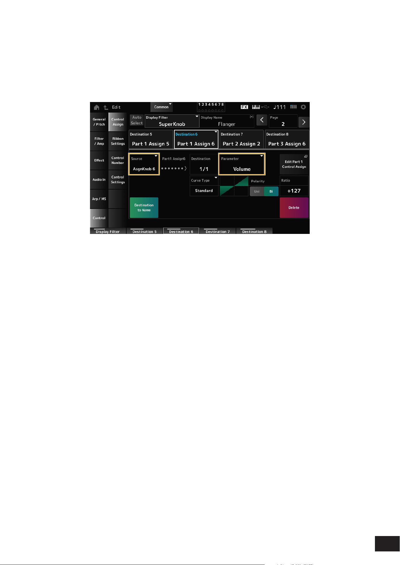
5-3.
Tap each of the Destination 6 to 8 tabs to check that the Source is set to AsgnKnob 6 to 8 respectively, and the
Destination Parameter is set to Part 1 to 3 Volume.
6.
Set the LEFT position on the Super Knob.
This makes the settings for the Super Knob when turned all the way to the left.
6-1.
Press the KNOB POSITION [LEFT] button.
6-2.
Make sure that the COMMON is selected for Part select and then press the [ASSIGN] button. Make sure that the
Knobs are set to 5 to 8.
6-3.
To set only the CFX PopStudioGrand on Part 1 to sound, turn Knob 6 (Assign6) all the way to the right (to the
maximum value) and Knob 7 (Assign7) and Knob 8 (Assign8) all the way to the left (to the minimum value).
6-4.
Save the settings by simultaneously holding down the [SHIFT] button and pressing the KNOB POSITION [LEFT]
button.
7.
Set the RIGHT position on the Super Knob.
This makes the settings for the Super Knob when turned all the way to the right.
7-1.
Press the KNOB POSITION [RIGHT] button.
7-2.
To set only the TV Show FM EP on Part 3 to sound, turn Knob 8 (Assign8) all the way to the right (to the maximum
value) and Knob 6 (Assign6) and Knob 7 (Assign7) all the way to the left (to the minimum value).
7-3.
Save the settings by simultaneously holding down the [SHIFT] button and pressing the KNOB POSITION [RIGHT]
button.
31
MODX M Operation Manual
8.
Set the MID position on the Super Knob.
Enable the MID position and then turn the Super Knob to set the value for the middle position.
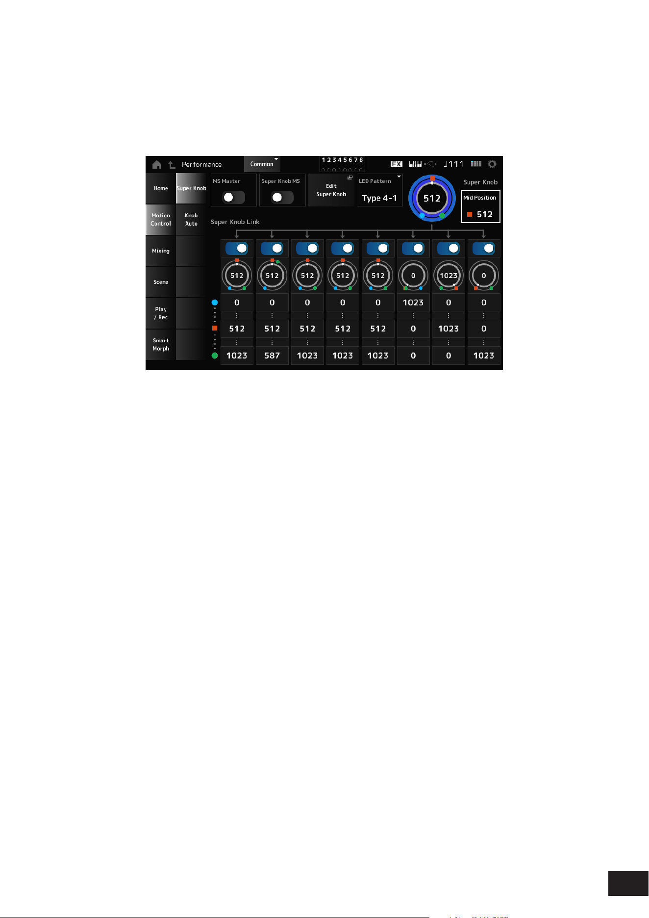
8-1.
Press the [NAVIGATION] button to open the NAVIGATION screen.
8-2.
Tap on Super Knob and open the screen for the Super Knob settings.
8-3.
Set the value 512 for the Mid Position.
8-4.
Press the KNOB POSITION [MID] button.
8-5.
To set only the AN-X Sine Pad PAT on Part 2 to sound, turn Knob 7 (Assign7) all the way to the right (to the maximum
value) and Knob 6 (Assign6) and Knob 8 (Assign8) all the way to the left (to the minimum value).
8-6.
Save the settings by simultaneously holding down the [SHIFT] button and pressing the KNOB POSITION [MID]
button.
The main setting is now complete.
9.
Make fine adjustments.
Adjust the Curve Type, Ratio, and Param for each Part, and LEFT, RIGHT, and MID for the KNOB POSITION if
desired.
32
MODX M Operation Manual
Using Motion Sequencer
The Motion Sequencer function lets you create sound changes by controlling parameter times according to a sequence
you create in advance. It allows you to set up rhythmical changes that are in sync with the Performance tempo, Arpeggio,
or the rhythms input from the connecting device and to control such changes interactively and in real-time according to
the progression of the song.
You can use up to four lanes in one Part, or up to eight lanes in an entire Performance. You can set up to eight sequence
patterns per lane. As with Arpeggios, you can set the Velocity Limit and sequence playback method, the number of steps,
etc. for playing back the sequence.
How to set the parameters for each lane:
[PERFORMANCE (HOME)]
→
Part selection
→
[EDIT/ ]
→
Motion Seq
→
Lane
Turning Motion Sequencer on or off
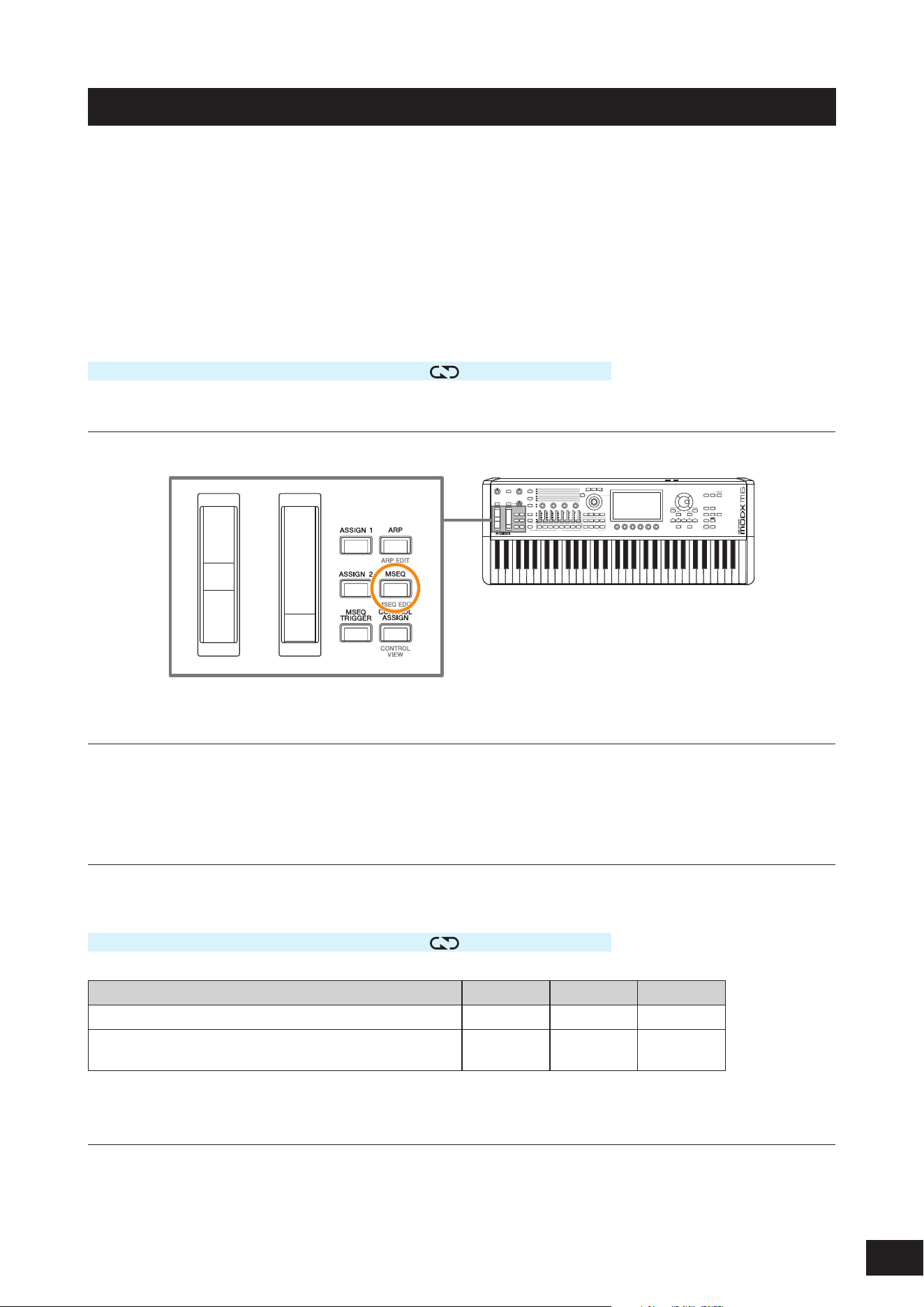
To turn Motion Sequencer on or off, press the [MSEQ] button on the top panel.
Changing Motion Sequencer by using the knobs
Select ARP/MSEQ with the [QUICK EDIT] button to use Knobs 3 and 4 to change Motion Sequencer.
Modify the Motion Sequencer settings by turning the knobs and listening to the Motion Sequencer playback.
For details on the effects of Knobs 3 and 4, refer to Arp/MS
→
MS Common on the Common Edit screen.
Changing the way Motion Sequence is triggered
The way Motion Sequencer is triggered can be set with the LaneSw and Trigger parameters.
LaneSw, Trigger
[PERFORMANCE (HOME)]
→
Part selection
→
[EDIT/ ]
→
Motion Seq
→
Lane
Setting Lane Sw Trigger Sync
Plays back the Motion Sequencer when you press a key On Off -
Plays back the Motion Sequencer when you press the [MSEQ
TRIGGER] button
On On Other than
Arp
Editing the Motion Sequencer
Motion Sequence is comprised of up to 16 steps.
Tap Edit Sequence to open the Motion Sequence settings screen, and edit each step.
33
MODX M Operation Manual
Using the Envelope Follower
Envelope Follower is the function that extracts the envelope of the waveform from the audio input and is used as
a controller for creating changes in the sound. It allows the output of Parts and the output from the external device
connected to the A/D INPUT jacks.
For example, you can use the Envelope Follower of one Part assigned a Rhythm Pattern as a source to add Variation to
another Part. It is useful, for example, when you wish to set ducking (lowering the volume of a Part while a certain other
Part is being played).
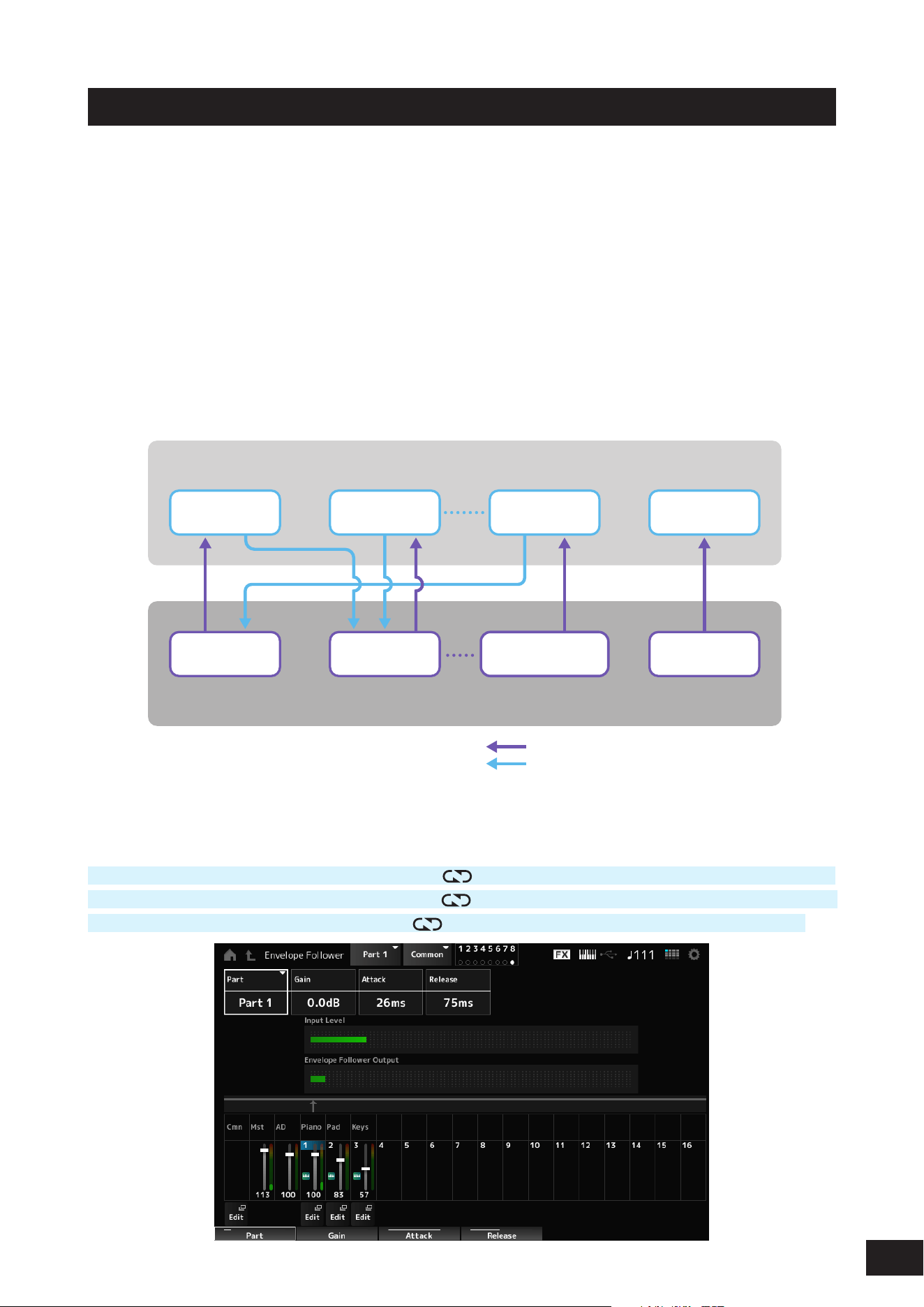
Each Envelope Follower has its own input source, such as EnvFollow 1 for Part 1, EnvFollow 2 for Part 2, and EnvFollow
AD for the Audio Part. The output from each Envelope Follower can be changed by selecting a different Source from the
Control Assign screen.
For example, you can set up the Envelope Follower for Part 1 (EnvFollow 1) to create changes in Part 2. How the sound
is modified by the output from each Envelope follower can be set from the Control Assign screen.
Envelope Follower
Input Source
Env Follower
MST
Env Follower
AD
Part 1
Performance
(16 parts and Audio Part)
A/D IN PartPart 2
Env Follower
2
EnvFollower
1
(1) Input signal to Envelope Follower (Fixed)
(2) Output signal from Envelope Follower
(The Destination can be changed)
(1) Input signal to Envelope Follower (2) Output signal from Envelope Follower
Settings for the Envelope Follower:
[PERFORMANCE (HOME)]
→
Common selection
→
[EDIT/ ]
→
Effect
→
Routing
→
Envelope Follower (EnvFollow MST)
[PERFORMANCE (HOME)]
→
Common selection
→
[EDIT/
]
→
Audio In
→
Routing
→
Envelope Follower (EnvFollow AD)
[PERFORMANCE (HOME)]
→
Part selection
→
[EDIT/
]
→
Effect
→
Routing
→
Envelope Follower (EnvFollow 1–16)
34
MODX M Operation Manual
Setting the Envelope Follower from the Rhythm Pattern screen
You can set the Envelope Follower on the Rhythm Pattern screen. This way, you can quickly access the Envelope
Follower parameters often used for the Rhythm Patterns.
1.
Press the [SONG/PATTERN] button while holding down the [SHIFT] button to open the Rhythm
Pattern screen.
2.
Select a drum sound from the list shown on the right side of the screen.
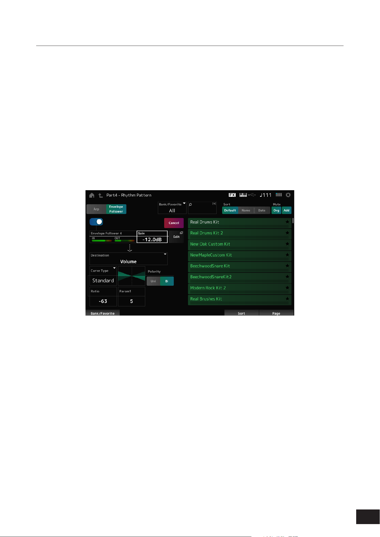
3.
Tap Envelope Follower and turn the switch on.
You can play the keyboard to hear the effect of the Envelope Follower.
4.
Adjust the settings.
Setting example
• Polarity (Curve Polarity): Bi
• Ratio (Curve Ratio): −63
• Gain (Envelop Follower Gain): −12.0 dB
5.
For finer adjustments, tap Edit on the screen.
The Envelope Follower Edit screen will open.
NOTE
• You can select a new kit or Arpeggio type for the Rhythm Pattern by simultaneously holding down the [SHIFT] button and pressing the
[SONG/PATTERN] button to go back to the Rhythm Pattern screen.
• The Envelope Follower settings are retained after selecting a new kit or Arpeggio for the Rhythm Pattern.

35
MODX M Operation Manual
Using Smart Morph
Smart Morph is a function that morphs FM-X Parts or AN-X Parts using machine learning. This allows you to create a new
sound for Part 1 from multiple FM-X Parts or AN-X Parts to play on the keyboard.
Features of Smart Morph
The Smart Morph function analyzes each sound assigned to Parts 9 to 16 and plots one dot per Part on the map. Each
dot on the map represents a sound, and the distance between dots shows the similarities of these sounds.
Creating a new part (Learn)
The Learn feature automatically generates sounds to fill in the gaps between dots on the map. When you tap the dot on
the map, the sound for that dot will be selected for Part 1. You can find a new place you like from the map and save its
settings to create a new part.
By dragging the dot on the map while playing the keyboard, or by moving the Super Knob with the movements of two to
eight dots assigned beforehand, you can create completely new sounds.
36
MODX M Operation Manual
Saving edited settings
After editing, save the Performance you have created in the internal memory. Saving the settings to internal memory is
referred to as the “Store” operation.
NOTICE
• When you select a different Performance or turn off the instrument without first storing the Performance, you will lose the
settings you are editing.
• The existing Performances on the User Bank will be lost when you overwrite them. When you save Performances you have
edited, make sure not to overwrite existing Performances. Important settings you’ve made should be saved to a USB flash
drive (Save). For the Save operation, see “Saving settings to a USB flash drive as a backup file (Save).”
How to store a Performance
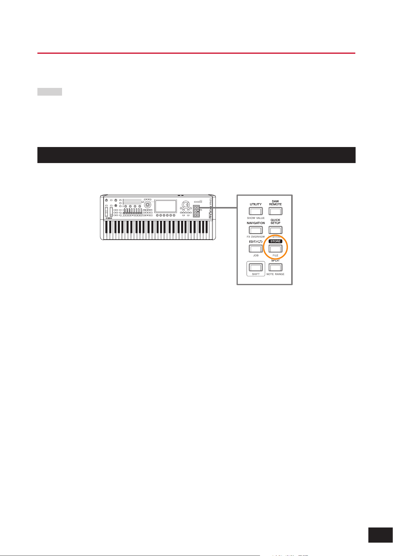
1.
Press the [STORE] button.
• If you are saving a new Performance, Store As New Performance will be displayed.
• If the Performance has already been stored, Overwrite Current Perf. and Store As New Performance will be
displayed.
2.
To store as a new Performance, tap Store As New Performance.
If you want to overwrite a Performance that has already been stored, tap Overwrite Current Perf. and then tap Store
(YES).
3.
Type in the Performance name on the Keyboard screen.
Use the keyboard shown on the Main display. You can use up to 20 alphanumeric characters.
4.
Tap Done when you have finished entering the name.
When the Store operation is complete, the Performance screen will be shown on the display.
37
MODX M Operation Manual
Creating a Live Set
The Live Set function is a convenient way to change among different Performances as you play songs on a setlist, for
example.
On this instrument, you can create a Live Set simply by registering your favorite Performance to each slot.
Registering a Performance to the slot
You can register a Performance to the Live Set by following the procedure below.
NOTICE
• Store the Performance you have just edited before registering the Performance to the Live Set. However, when you register
to the Live Set and select Store As New Perf. and Register or Overwrite Current Perf. and Register, you do not need to store
the Performance in advance.
• When you select a different Performance or turn off the instrument without first storing the Performance, you will lose the
edited settings you have made.
1.
Select a Performance from the Performance screen.
Make sure the [LIVE SET] button is lit or semi-lit.
2.
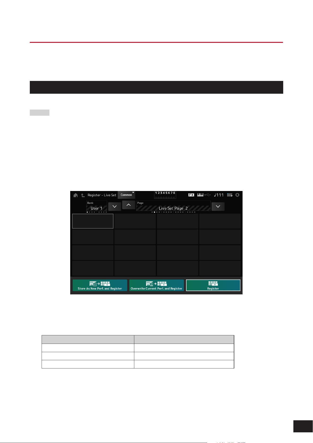
Simultaneously hold down the [SHIFT] button and press the [LIVE SET] button.
The Live Set Register screen appears.
3.
Tap the slot you want to register to select it.
4.
Select one of the available store operations and press the [ENTER] button, or simply tap your
selection on the screen.
Storage method Description
Store As New Perf. and Register Stores as a new Performance and registers
Overwrite Current Perf. and Register Overwrites the current Performance and registers
Register Registers
Change the Performance name as needed. Confirm the changes to register the Performance in the slot.
NOTE
If you want to register a new Performance before an already registered slot, follow the steps below.
1. Simultaneously hold down the [SHIFT] button and tap the slot. A cursor will appear in front of the slot.
2. While holding down the [SHIFT] button, select the storage method and press the [ENTER] button or tap the screen.
At this time, the Performance registered in the last slot (bottom right) of the Live Set page will be deleted.
38
MODX M Operation Manual
Exchanging Performances registered to slots
You can exchange the contents of slots.
1.
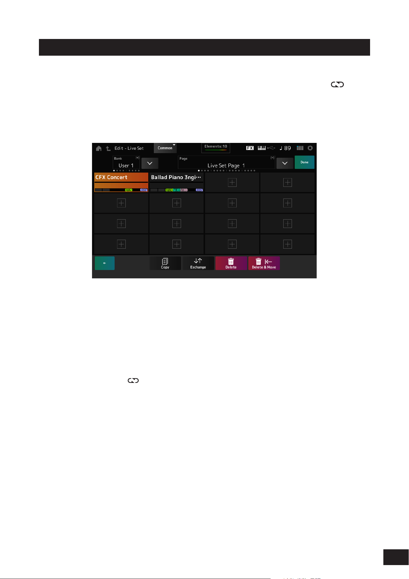
Open the screen from: [LIVE SET] (or Live Set icon)
→
User Bank selection
→
[EDIT/ ].
The Live Set Edit screen appears.
When the Live Set page on the Preset bank or the Library bank is open, the Live Set Edit screen will not appear.
2.
Tap Job on the screen.
The Jobscreen will appear at the bottom of the screen.
3.
Tap the slot you wish to move the Performance from, and then tap Exchange.
The Jobscreen will appear at the bottom of the screen.
4.
Tap the slot you wish to move the Performance to.
The Performances of the two slots will be exchanged.
5.
Once the exchange is complete, tap Done.
NOTE
If you wish the copy or exchange the entire Bank or the entire Page, with the Live Set screen displayed, simultaneously hold down the
[SHIFT] button and press the [EDIT/ ] button. Then the dialog box will appear.
39
MODX M Operation Manual
Registering a Pattern, Song, or Audio file to the slot
You can also add Patterns, Songs, or Audio files to Live Set slots. This way, you can select a slot for playing back a desired
Pattern, Song, or Audio file, and then play the Performance on the keyboard along with it.
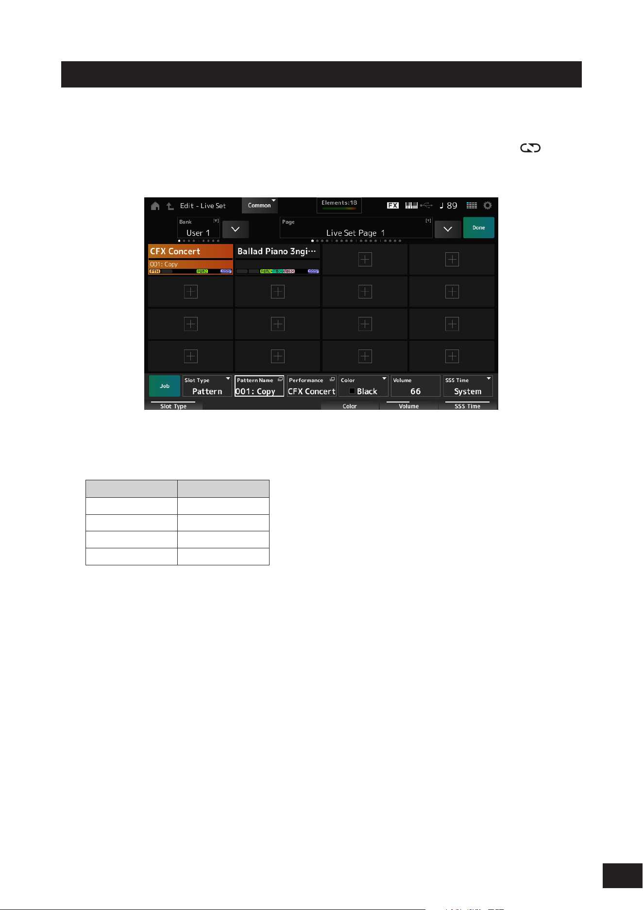
1.
Open the screen from: [LIVE SET] (or Live Set icon)
→
User Bank selection
→
[EDIT/ ].
The Live Set Edit screen appears.
When the Live Set page on the Preset bank or the Library bank is open, the Live Set Edit screen will not appear.
2.
Select a slot or tap [+] on the screen.
3.
Select the slot you want to register from Slot Type.
Slot Type Type
Perform Performance
Song Songs
Audio Audio file
Pattern Patterns
4.
Tap Pattern Name, Audio Name, etc. to open the Load screen.
5.
Select the desired pattern or file to register to the slot.
6.
Once the settings are complete, tap Done.
NOTE
You can also register a Pattern or Song to the Live Set by pressing the [SHIFT] and [LIVE SET] buttons on the Pattern screen or Song
screen.
40
MODX M Operation Manual
Exchanging slots with the foot switch
You can select a different Live Set slot by using a separately sold foot switch, such as the FC4A or FC5.
Follow the procedure below.
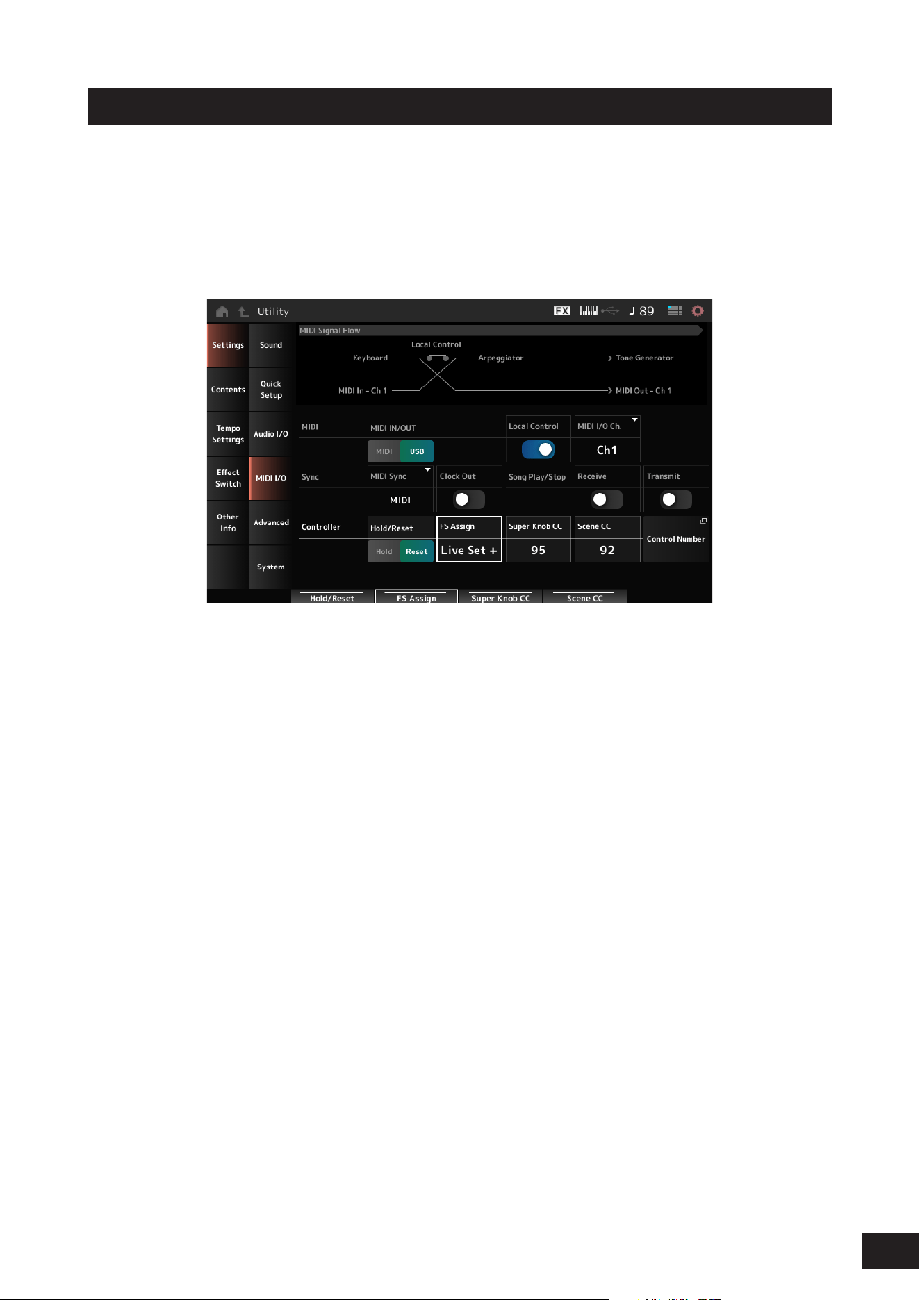
1.
Connect a foot switch (FC4A or FC5) to the FOOT SWITCH [ASSIGNABLE] jack.
2.
Open the screen as follows: [UTILITY]
→
Settings
→
MIDI I/O.
The MIDI I/O screen appears.
3.
Set FS Assign to either Live Set+ or Live Set−.
With Live Set+, you can select the next Live Set slot in forward order.
With Live Set−, you can select the next Live Set slot in reverse order.
41
MODX M Operation Manual
Selecting Performances from a Live Set
Select Performances for a setlist from the Live Set screen.
1.
Press the [LIVE SET] button to open the screen.
The Live Set screen appears.
2.
Switch between Bank and Page as needed.
3.
Tap a slot to select it.
The Performance for the setlist will be selected.

42
MODX M Operation Manual
Playing the keyboard
Make sure to select a Performance from the Live Set before playing the keyboard.
If desired, you can also play back a specific Pattern, Song, or Audio file (registered to a Live Set slot) along with your
keyboard performance.
Playing back a Pattern, Song, or Audio file registered to a Live Set slot
You can play the keyboard along with the Pattern, Song, or Audio file registered to the slot.
NOTE
While the Song or Pattern is being played back, you cannot change the Performance or select a different slot. If you attempt to change
them, an error message will appear.
1.
Select a slot on the Live Set screen.
2.
Press the [
] (Play) button.
The Pattern, Song, or Audio file registered to the selected slot will then play back.
NOTE
While the Pattern, Song, or Audio file is played back, pressing the [
] (Play) button shows the same screen as the Pattern screen,
Song screen, or Audio screen.
3.
Press the [
] (Stop) button to stop playback.

43
MODX M Operation Manual
3. Recording and Playback
You can use this instrument to record and play back Patterns, Songs, and Audio les.
Patterns and Songs are recorded in the storage area within the instrument, while Audio les are recorded to a connected
USB ash drive.
Terminology
Patterns
Patterns are comprised of MIDI sequence data, containing short phrases recorded as MIDI events. They can be played
back in a loop or used with the Scene function. This instrument can hold up to 128 Patterns within the memory area.
Songs
Songs are comprised of MIDI sequence data, containing information on the operation of the keyboard and other
controllers recorded as MIDI events. This instrument can hold up to 128 Songs within the memory area.
Tracks
Tracks are separate storage locations for recording the keyboard performance. A track holds the information for one Part.
A maximum of 16 tracks are available on this instrument, so you can use up to 16 Parts for recording and playing back.
44
MODX M Operation Manual
Recording and playing back patterns
Record a melody on a track.
Recording a Pattern
1.
Select the desired sound for recording on Track 1.
2.
Press the [SONG/PATTERN] button and tap Pattern.
The Pattern screen appears.
NOTE
You can also open the same screen from the [PERFORMANCE (HOME)] button
→
Play/Rec
→
Pattern.
3.
Change the scene length (Length), tempo (Tempo), and other settings as needed.
4.
Press one of the [SCENE] buttons to select the desired Scene for recording.
5.
Press the [
] (Record) button.
Recording will be set to standby.
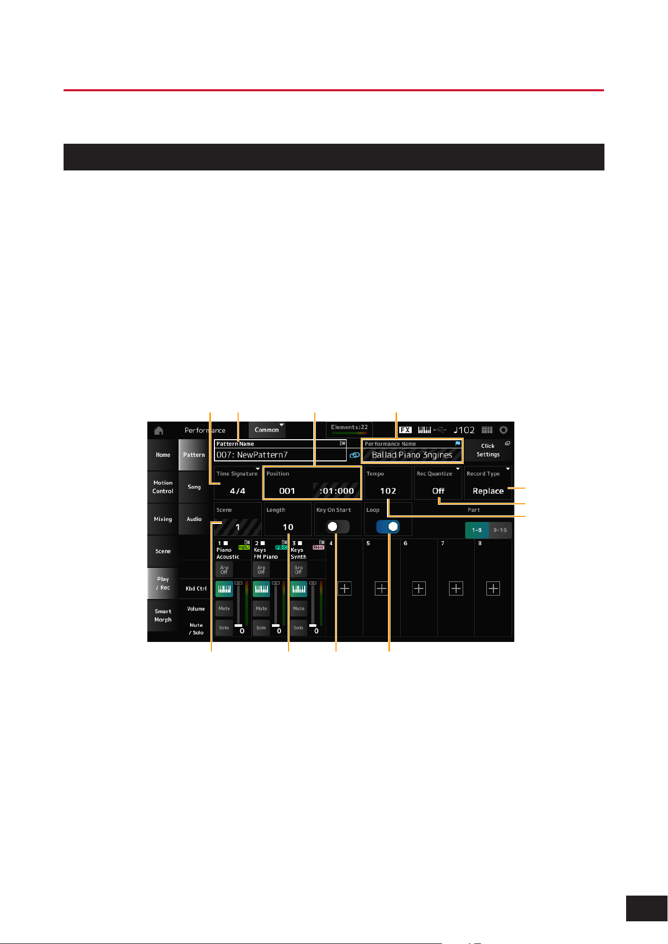
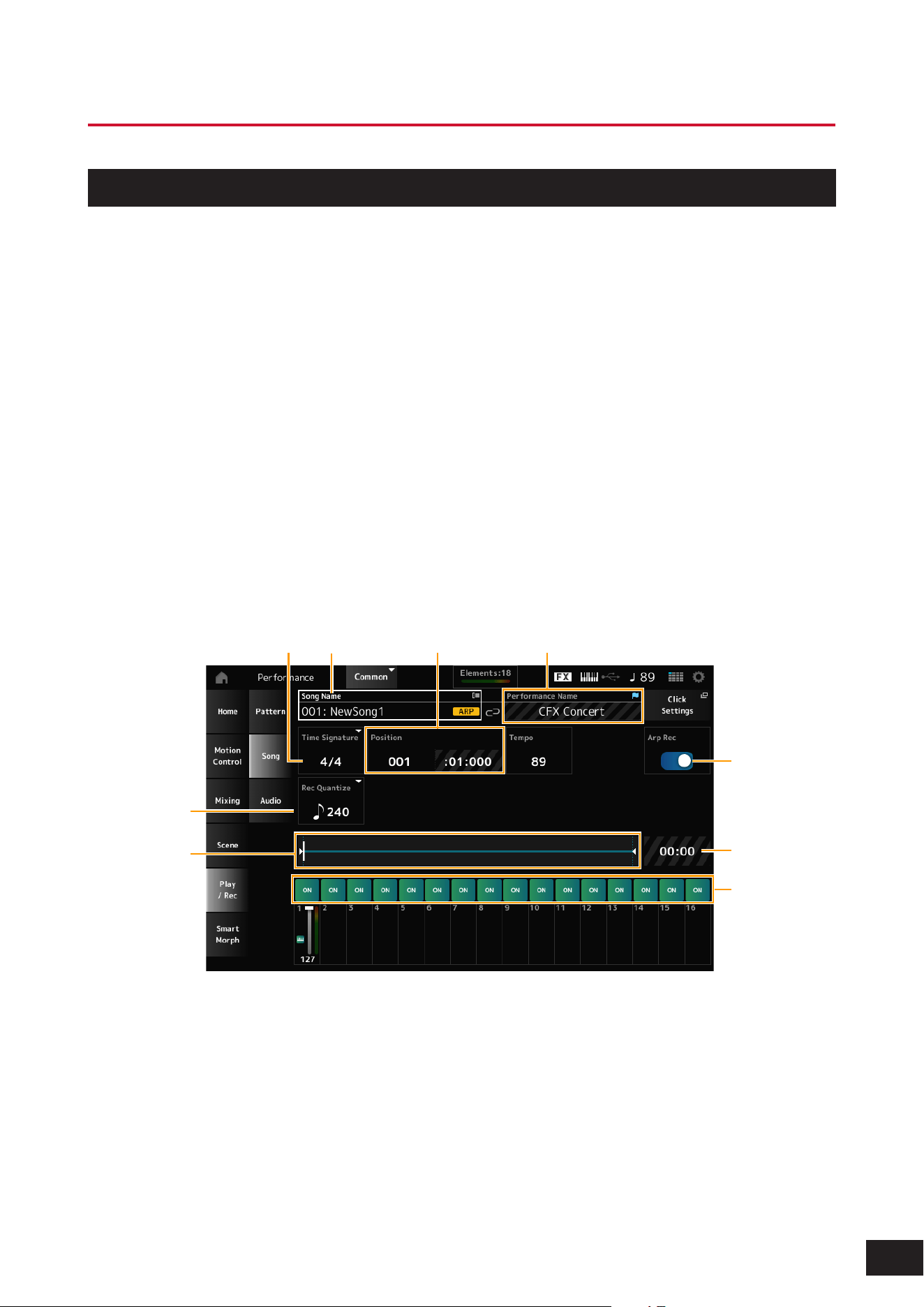
(1) (2)(3) (4)
(6)
(8) (9) (10) (11)
(5)
(7)
(1) Pattern name
(2) Name of the Performance currently selected
(3) Time signature
(4) Position for starting playback and recording
( 5) Te m p o
(6) Quantize
(7) Switching recording types (not shown when
recording a new pattern)
(8) Scene
(9) Length of the pattern
(10) Turning on or off the function to start recording
at key-on
(11) Turning the loop setting on or off
45
MODX M Operation Manual
6.
Press the [
] (Play) button to start recording.
7.
Play the keyboard.
When Loop is on, the phrase you play while recording will be played back in a loop, allowing you to record it onto
another track while maintaining the recording status.
NOTE
When you press the [
] (Record) button during recording, it will flash and Rehearsal mode is enabled. In this mode, you can
temporarily disable recording on a track while continuing to play back. This is useful when you want to try out a sound.
Pressing the [
] (Record) button again while in Rehearsal mode will return you to Recording mode.
8.
Select the desired sound for Track 2, and play the keyboard along with the phrase you recorded
on Track 1.
9.
Record other tracks as needed.
Songs and Patterns are stored automatically when recorded.
If you want to change the tempo or tone of a song or pattern after recording and then store it, tap Store Pattern&Perf
Settings (or Store Song&Perf Settings for a song) to store it.
NOTE
If you have edited the Performance parameters, you will also need to store the Performance.
Canceling the last recording action (Undo, Redo)
Undo cancels the last recording action and deletes what has been just recorded.
Redo restores the recording that has been canceled by Undo.
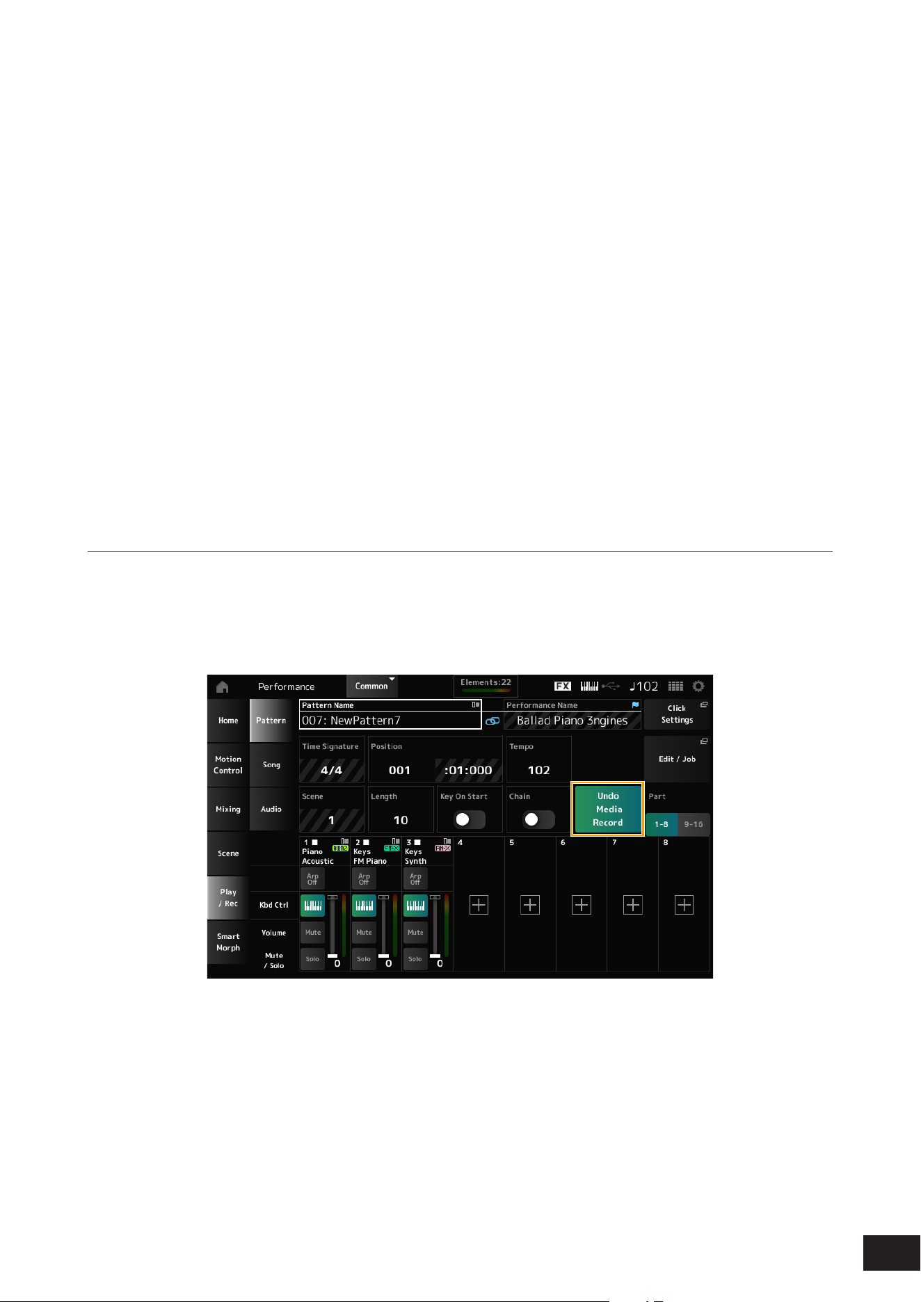
Undo Media Record
(does not appear when there are no recordings)
Tapping this cancels the last recording action and restores the recording to its original state.
46
MODX M Operation Manual
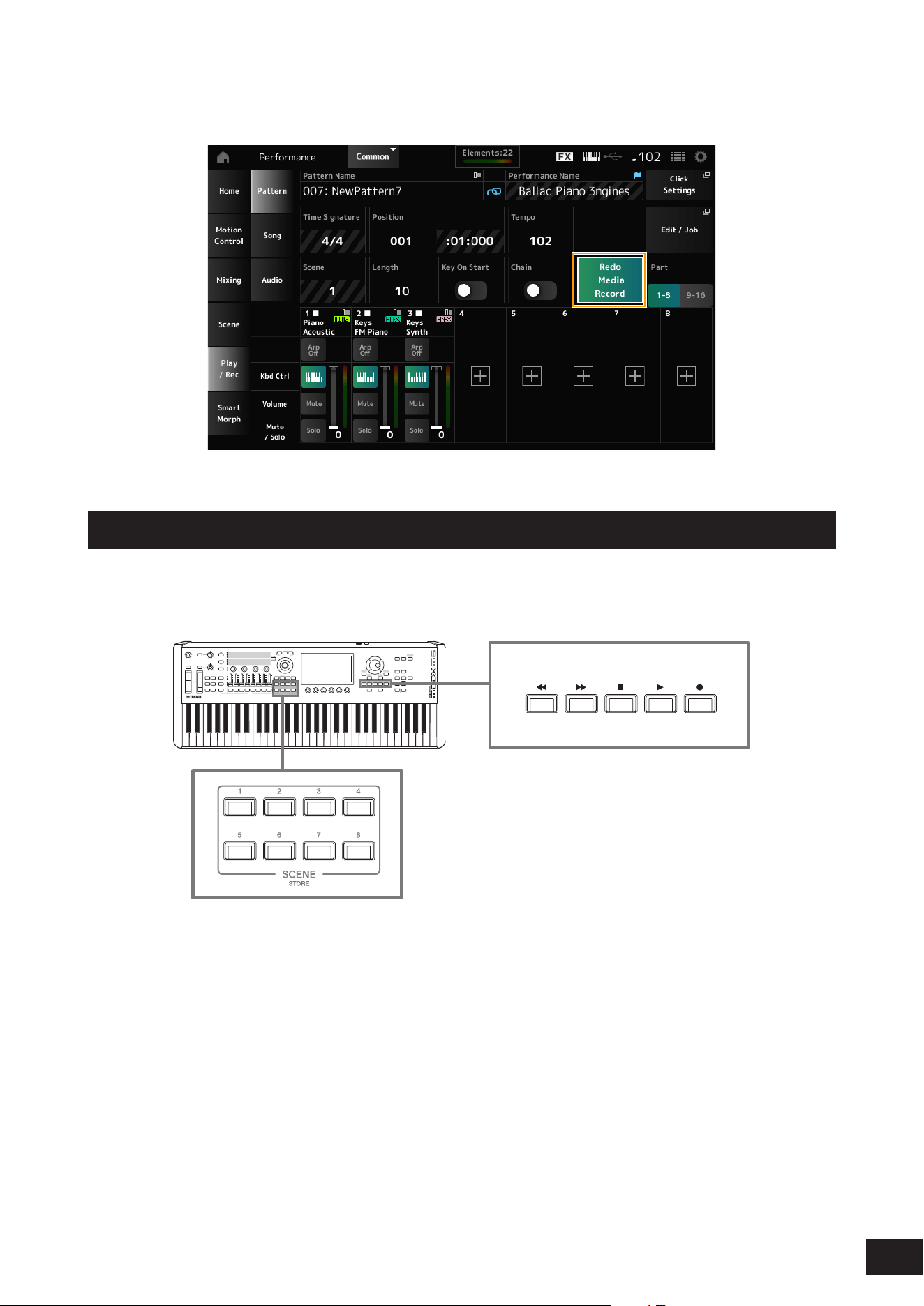
Redo Media Record
(does not appear until Undo has been done)
Tapping this restores the recording to its state before Undo.
Playing back the Pattern
To play back the recorded Pattern, use the Sequencer Transport buttons.
You can use the SCENE buttons to select a Scene for playback.
47
MODX M Operation Manual
Recording and playing back songs
Recording a Song
Not only the keyboard performance, but also the operations of the controllers and knobs are recorded to a track as MIDI
data.
When you play the keyboard or operate a controller, the parts with the Keyboard Control Switch On will be recorded.
For the knob operations, Control Change and Parameter Change messages will also be recorded. For more information
on Control Change, refer to the Data List.
NOTE
• When Arp Rec is On, only the result of the Arpeggio playback is recorded.
• When Arp Rec is Off, data of the entire keyboard performance is recorded, enabling you to change the Arpeggio patterns later.
1.
Select a Performance.
2.
Press the [SONG/PATTERN] button to open the Play/Rec screen and select the Song tab, and
then press the [
] (Record) button.
The [
] (Record) button flashes, and recording is set to standby.
NOTE
Recording can also be set to standby by opening the screen from: [PERFORMANCE (HOME)]
→
Play/Rec
→
Song and pressing
the [
] (Record) button.
3.
Change the Time Signature and Rec Quantize as needed.
(1) (2)(3) (4)
(9)
(8)
(6)
(5)
(7)
(1) Song name
(2) Name of the Performance currently selected
(3) Time signature
(4) Position for starting playback and recording
(5) Quantize
(6) The total length of the sequence and the current
position for playback
(7) Time for the entire sequence
(8) Setting the track on or off for playback
(9) Turning Arpeggio recording on or off
(only for a new recording)
48
MODX M Operation Manual
4.
When the preparation is complete, press the [
] (Play) button to start recording.
If the Click Settings is set, the Precount starts when you press the [
] (Play) button. Start playing the keyboard after
the precount.
5.
When the keyboard performance is finished, press the [
] (Stop) button to stop recording.
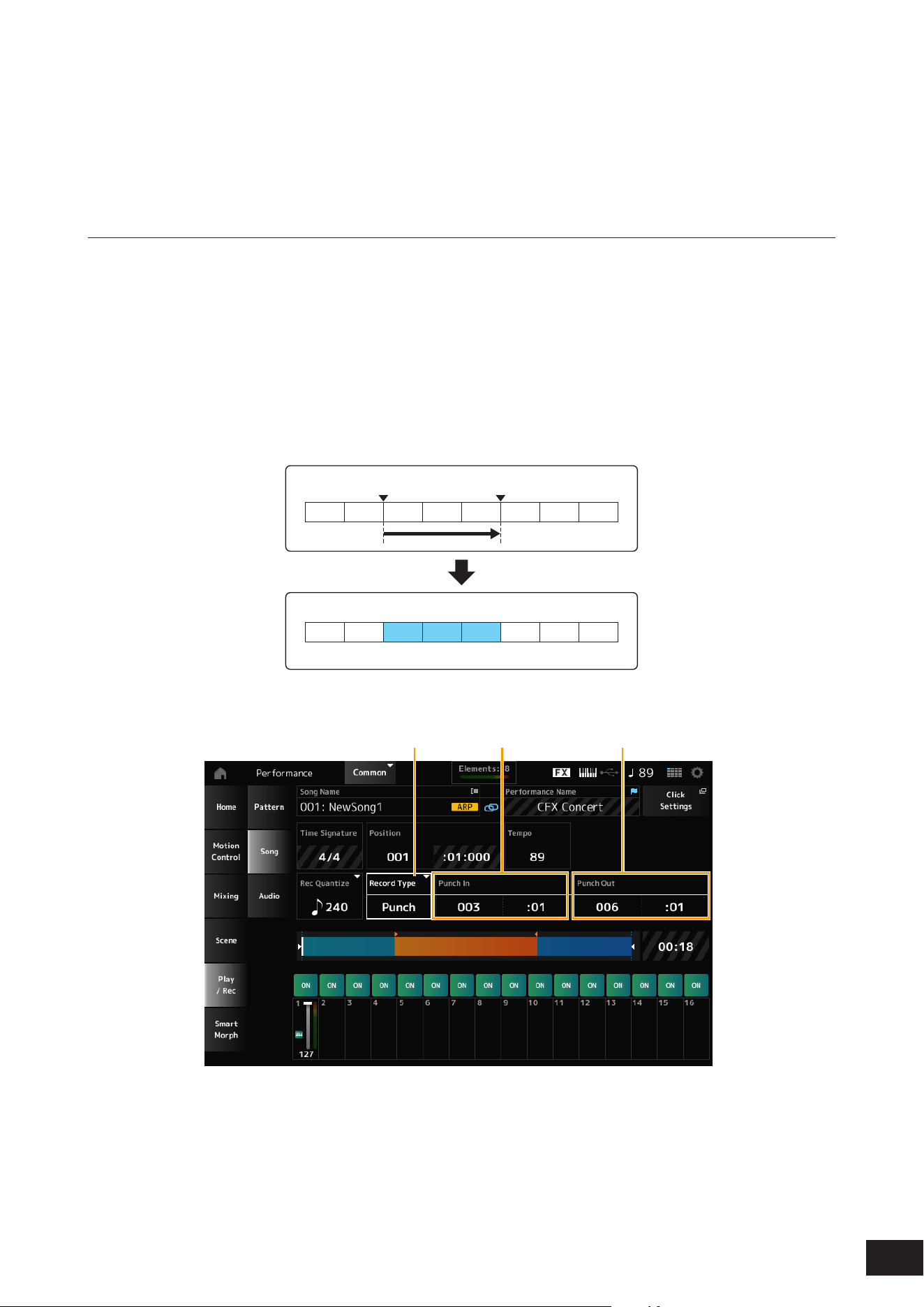
Recording some parts again (Punch-in / Punch-out recording)
There are three types of recording (Record Type) available on this instrument: Replace, Overdub, and Punch.
• Replace: overwrites the existing data.
• Overdub: adds a layer to the existing sound on the track.
• Punch: overwrites the specified section of the existing data.
If you wish to rerecord a specified section, you can set up the Punch-in / Punch-out parameters for the Punch recording.
When you start the Punch recording, the recorded Song will be played back from the beginning. When the playback
reaches the measure set for Punch-in, the recording starts automatically. The recording ends automatically when it
reaches the measure set for Punch-out, and the rest of the recorded Song will be played back to the end. For example, if
you wish to rerecord measures 3 to 5 of an eight-measure Song, follow the instructions shown below.
1
2 3 4 5 6 7 8
1 2 3 4 5 6 7 8
Punch In Punch Out
For the above Punch-in / Punch-out recording, set up the following parameters in the Record Setup screen.
(1) (2) (3)
(1) Record Type = Punch
(2) Punch In (Measure and beat to start rerecording) = 003:01
Starting from the measure and beat specified here, the sound of the corresponding track will be turned off and your
keyboard performance will be recorded.
(3) Punch Out (Measure and beat to end rerecording) = 006:01
Starting from the measure and beat specified here, the track will be played back.
49
MODX M Operation Manual
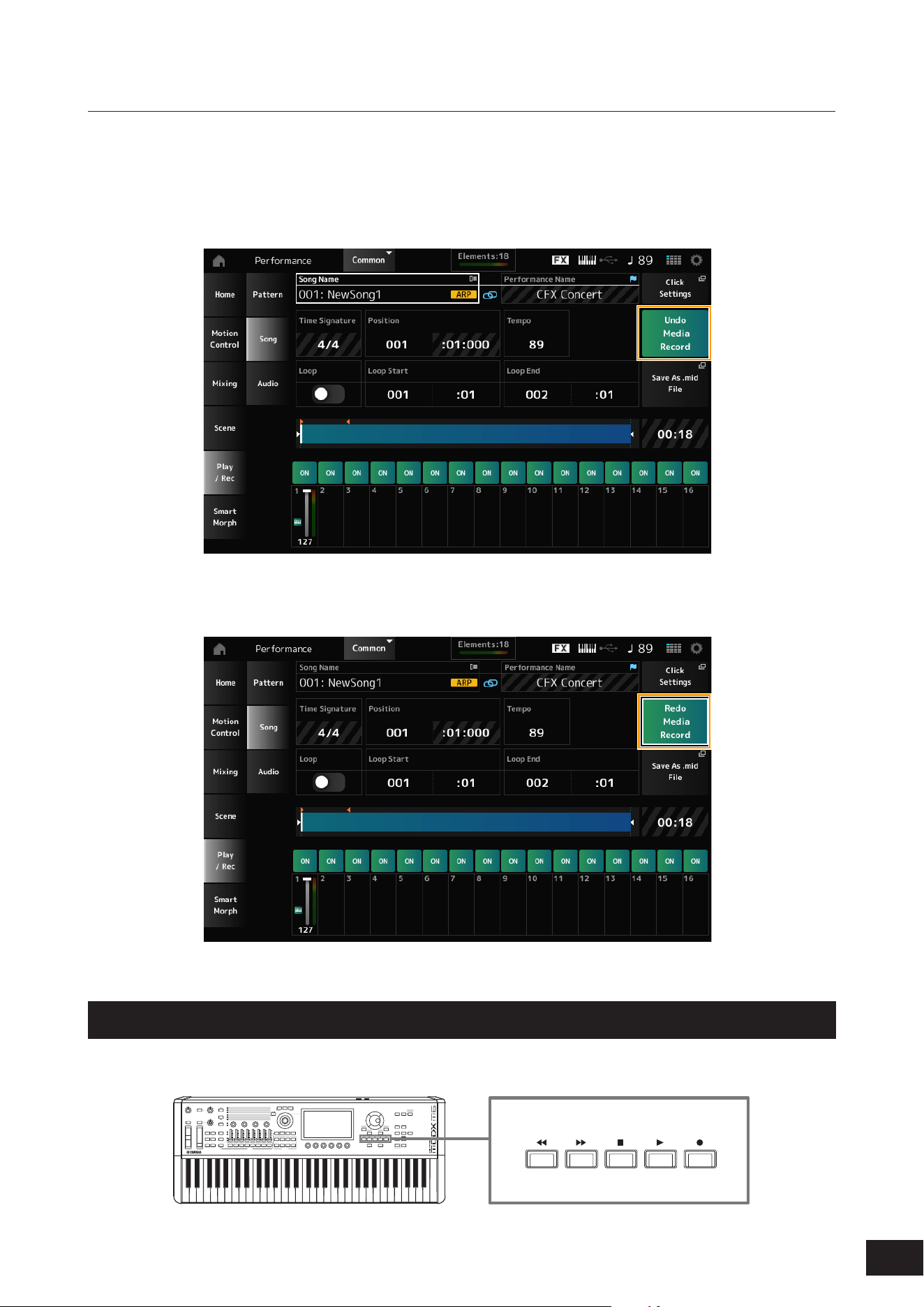
Canceling the last recording action (Undo, Redo)
Undo cancels the last recording action and deletes what has been just recorded.
Redo restores the recording that has been canceled by Undo.
Undo Media Record
(does not appear when there are no recordings)
Tap to see the confirmation screen. Continue(YES) cancels the last recording action and restores the recorder to its
original state.
Redo Media Record
(does not appear until Undo has been done)
Tap to see the confirmation screen. Continue(YES) restores the recording to its state before Undo.
Playing back the Song
To check the recorded Song, use the Sequencer Transport buttons.
50
MODX M Operation Manual
Recording audio and playing back audio files
Recording audio
You can use this instrument to record and playback Audio files in stereo (44.1 kHz, 24-bit wav). The recording level is
fixed, and it is possible to record continuously for up to 74 minutes (assuming that the USB storage device has sufficient
free memory).
1.
Connect a USB flash drive to the USB [TO DEVICE] terminal of the instrument.
2.
Opens the screen from: [PERFORMANCE (HOME)]
→
Play/Rec
→
Audio.
The audio recording screen appears.
3.
Press the [
] (Record) button.
The [
] (Record) button flashes, and recording is set to standby.
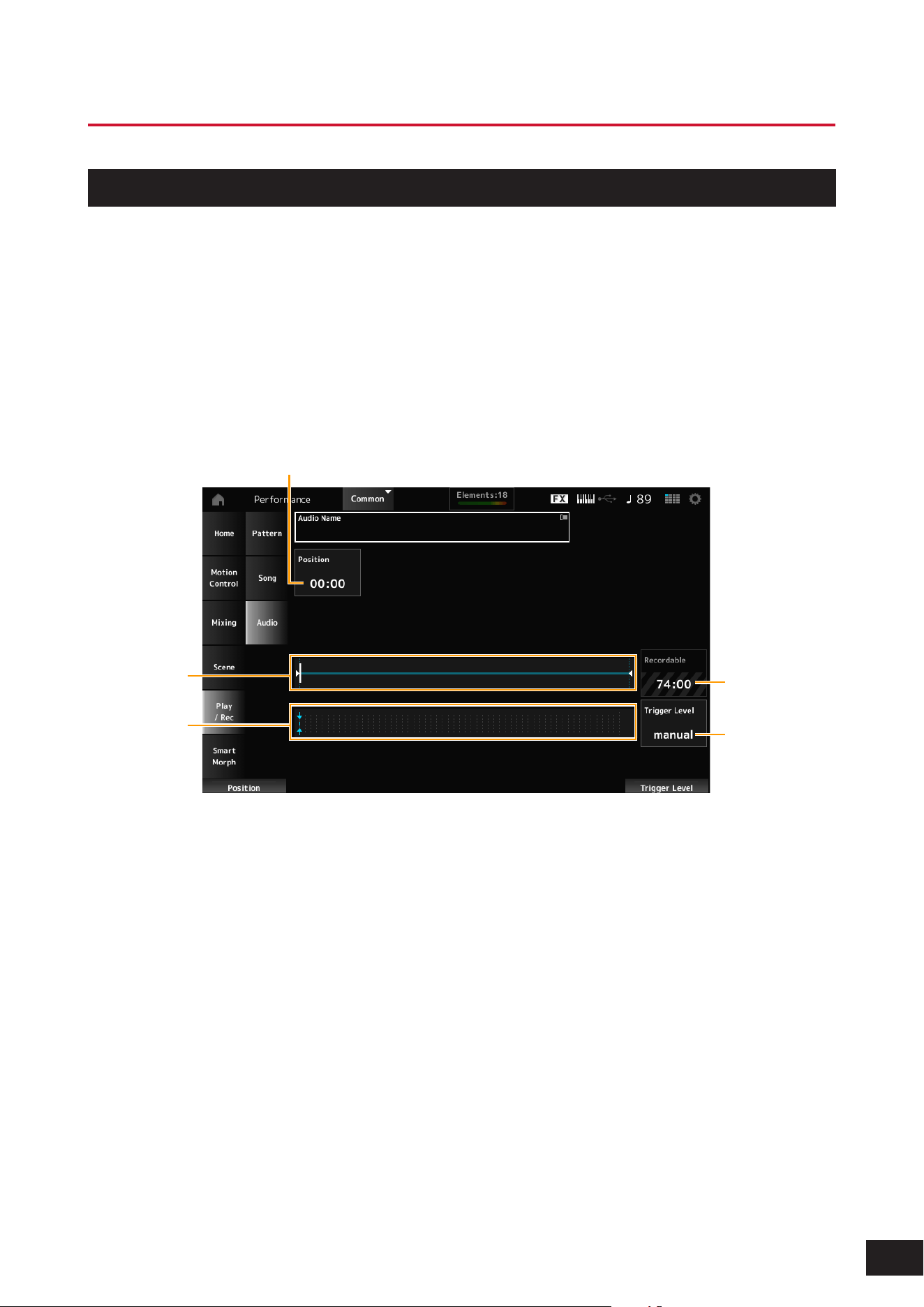
(1)
(5)
(2)
(4)
(3)
(1) Position for recording
(2) The total length of the audio file and the current position for recording
(3) Available recording time
(4) Level meter
(5) Trigger Level
4.
Sets the Trigger Level.
If you set the Trigger Level to manualrecording will begin whenever you press the [
] (Play) button.
Alternatively, if you set the Trigger Level to a value between 1 and 127, recording will begin automatically after you
have pressed the [
] (Play) button and then whenever playback volume exceeds that level.
The set Trigger Level will be indicated by a blue line in the level meter (4). For best results, set this parameter as low
as possible to capture the entire signal, but not so low as to record unwanted noise.
5.
Press the [
] (Play) button.
If you have set the Trigger Level to manual, recording will begin immediately right after you press the [
] (Play)
button. While recording, the [
] (Record) button will light in red, and the [
] (Play) button will light in green.
If you have set a value between 1 and 127 as the Trigger Level, the recording will begin automatically whenever the
playback volume exceeds that level.
51
MODX M Operation Manual
6.
Play the keyboard.
7.
When you have finished playing, press the [
] (Stop) button.
The recorded audio file will be saved to the USB flash drive.
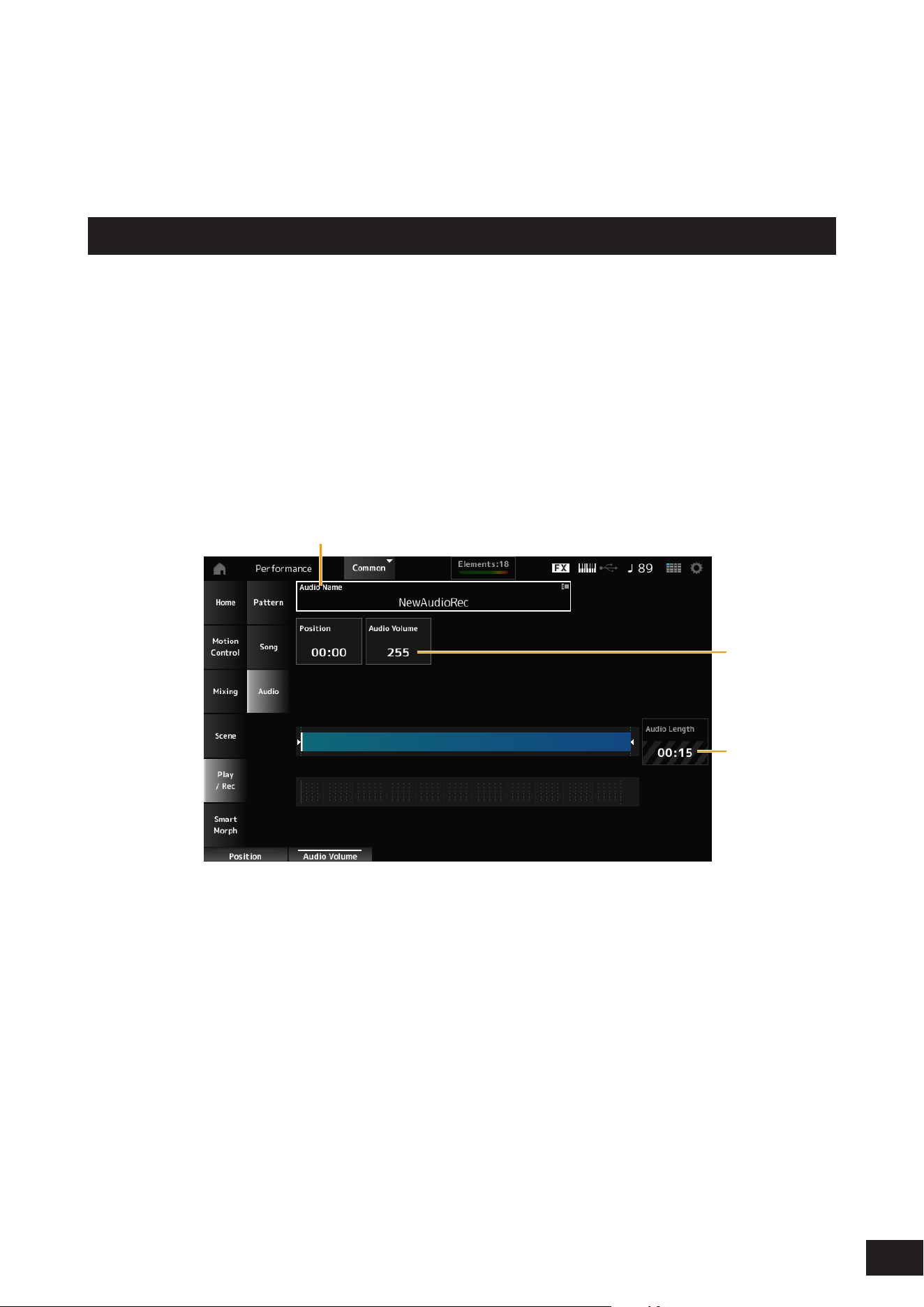
Playing an audio file
As described below, this instrument can play audio files (44.1 kHz, 24-bit or 16-bit .wav in stereo) from a USB flash drive.
You can also play a Performance on the keyboard while playing back the audio file.
1.
Connect a USB flash drive to the USB [TO DEVICE] terminal of the instrument.
2.
Opens the screen from: [PERFORMANCE (HOME)]
→
Play/Rec
→
Audio.
3.
Tap Audio Name (1), then tap Load in the context menu.
4.
Select the desired source USB flash drive and folder that contains the settings.
5.
Select the desired .wav file on the USB flash drive to load.
(1)
(3)
(2)
(1) Audio name
(2) Volume for playback
(3) Audio length
6.
Press the [
] (Play) button.
The audio file will play back.
7.
Move the cursor to Audio Volume (2), and then adjust the playback volume by using the Data dial.
8.
Press the [
] (Stop) button to stop playback.

52
MODX M Operation Manual
4. Managing Back Ups
You can save backups of the Performances, Live sets, and the Utility settings you have created and saved (stored) on the
instrument to a USB ash drive, as well as load settings from backup les from the USB ash drive to this instrument.
This section covers how to save all settings in the User memory to a USB ash drive and how to load your settings back
to the instrument.
The performance settings created on this device can also be backed up using Soundmondo (a sound management and
sharing service).
Soundmondo: https://www.yamaha.com/2/soundmondo
Available file formats
Saving to USB flash drive
Formats common to MONTAGE M and MODX M
• Backup le (.Y2A)
Everything in User memory (including the User area, Library area, Songs, and Patterns)
• User les (.Y2U)
Everything in the User area of User memory (including the Utility settings and Quick Setups)
• Library les (.Y2L)
User area in User memory (Excluding utility settings and quick setup. Live Set is 1 bank only
If the le size is larger than approximately 2 GB, the le will be divided in two. Split les will have different le extensions.
• Backup les (.Y2B)
• User les (.Y2W)
• Library les (.Y2M)
Generic file formats
• Patterns and Songs (.MID)
Patterns and Songs saved to User memory

53
MODX M Operation Manual
Loading from a USB flash drive
Files saved on the MONTAGE M and MODX M (.Y2A, .Y2U, .Y2L, .MID)
Generic file formats
• Audio les (.WAV and .AIF)
Files used as User Waveforms
• MIDI les (.MID)
Files used as Patterns and Songs
File formats used for older models
• MONTAGE (.X7A, .X7U, .X7L)
• MODX, MODX+ (.X8A, .X8U, .X8L)
• MOTIF XF (.X3A, .X3V, .X3G, .X3W)
• MOTIF XS (.X0A, .X0V, .X0G, .X0W)
• MOXF (.X6A, .X6V, .X6G, .X6W)
NOTE
If the backup le saved on the MONTAGE M exceeds the capacity of the MODX M's user waveform memory, that le cannot be loaded.
54
MODX M Operation Manual
The USB flash drive will be formatted.
We recommend formatting the USB flash drive on the instrument. USB flash drives formatted on other devices may not
work properly with this instrument.
NOTICE
Formatting a USB flash drive will erase all data stored on it. Please make sure that there is no necessary data on the card
before formatting.
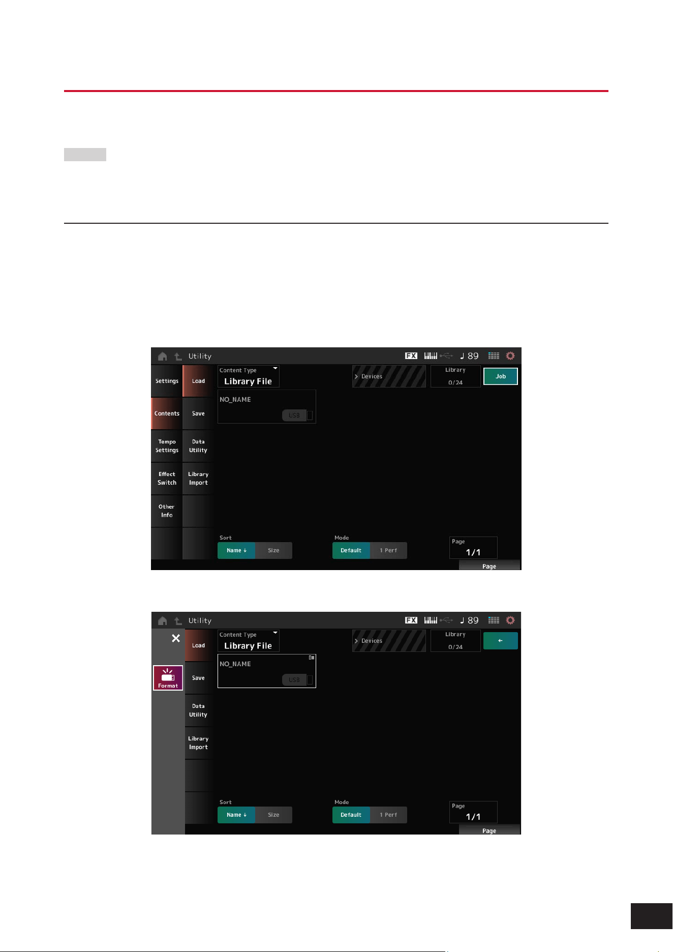
Formatting Procedure
1.
Connect a USB flash drive to the USB [TO DEVICE] terminal of the instrument.
2.
Open the screen by going to [UTILITY]
→
Contents
→
Load.
You can open the same screen by simultaneously holding down the [SHIFT] button and pressing the [STORE]
button.
3.
Tap Job in the upper right corner of the screen, then tap the connected USB flash drive.
4.
Tap Format in the context menu.
5.
Tap Format(YES).
Formatting is complete.
55
MODX M Operation Manual
Saving settings to a USB flash drive
1.
Connect a USB flash drive to the USB [TO DEVICE] terminal of the instrument.
2.
Open the screen by going to [UTILITY]
→
Contents
→
Save.
You can open the same screen by simultaneously holding down the [SHIFT] button and pressing the [STORE]
button, and then selecting the Save tab.
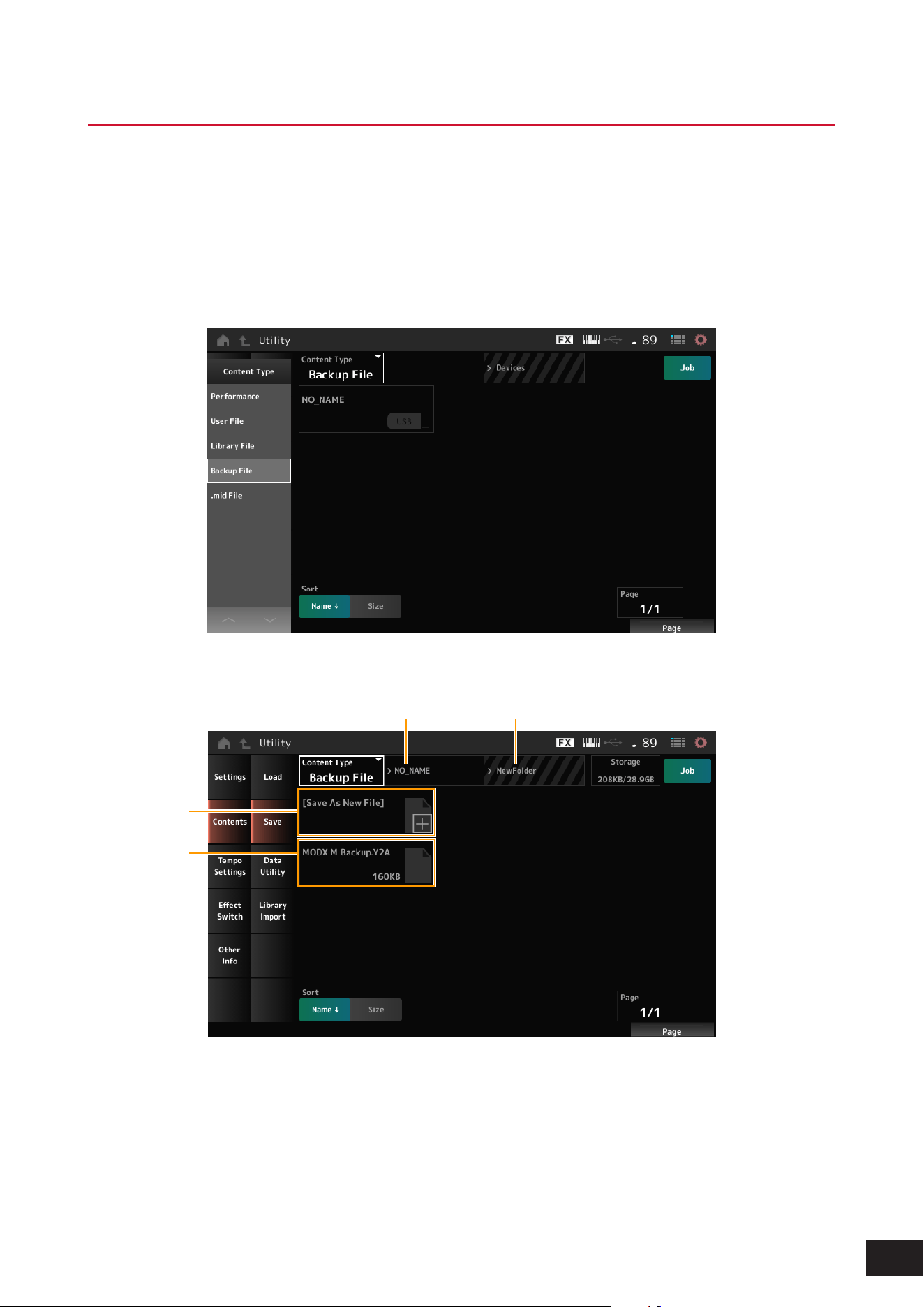
3.
Under Content Type, select Backup File.
4.
Select the USB flash drive and desired folder for saving the file.
(1) (2)
(3)
(4)
(1) Parent folder name
(2) Name of the destination folder currently selected in the USB flash drive
(3) Save to
(4) List of files already saved in the folder

56
MODX M Operation Manual
5.
Tap [+] for Save As New File.
This calls up the screen for entering names.
NOTE
To overwrite the existing file, confirm the process by tapping the file name on the screen. Tap Save(YES) to save the file.
6.
Enter the file name you wish to use.
For specific information on how to enter file names, refer to the Quick Guide.
7.
Tap Done to finish entering the name.
The backup file will then be saved to the USB flash drive.
57
MODX M Operation Manual
Loading settings from a USB flash drive
NOTICE
When settings are loaded, the existing settings on the instrument will be overwritten and lost. Important settings you want to
keep should be saved to a USB flash drive (Save) before loading the settings.
1.
Connect a USB flash drive to the USB [TO DEVICE] terminal of the instrument.
2.
Open the screen by going to [UTILITY]
→
Contents
→
Load.
You can open the same screen by simultaneously holding down the [SHIFT] button and pressing the [STORE]
button.
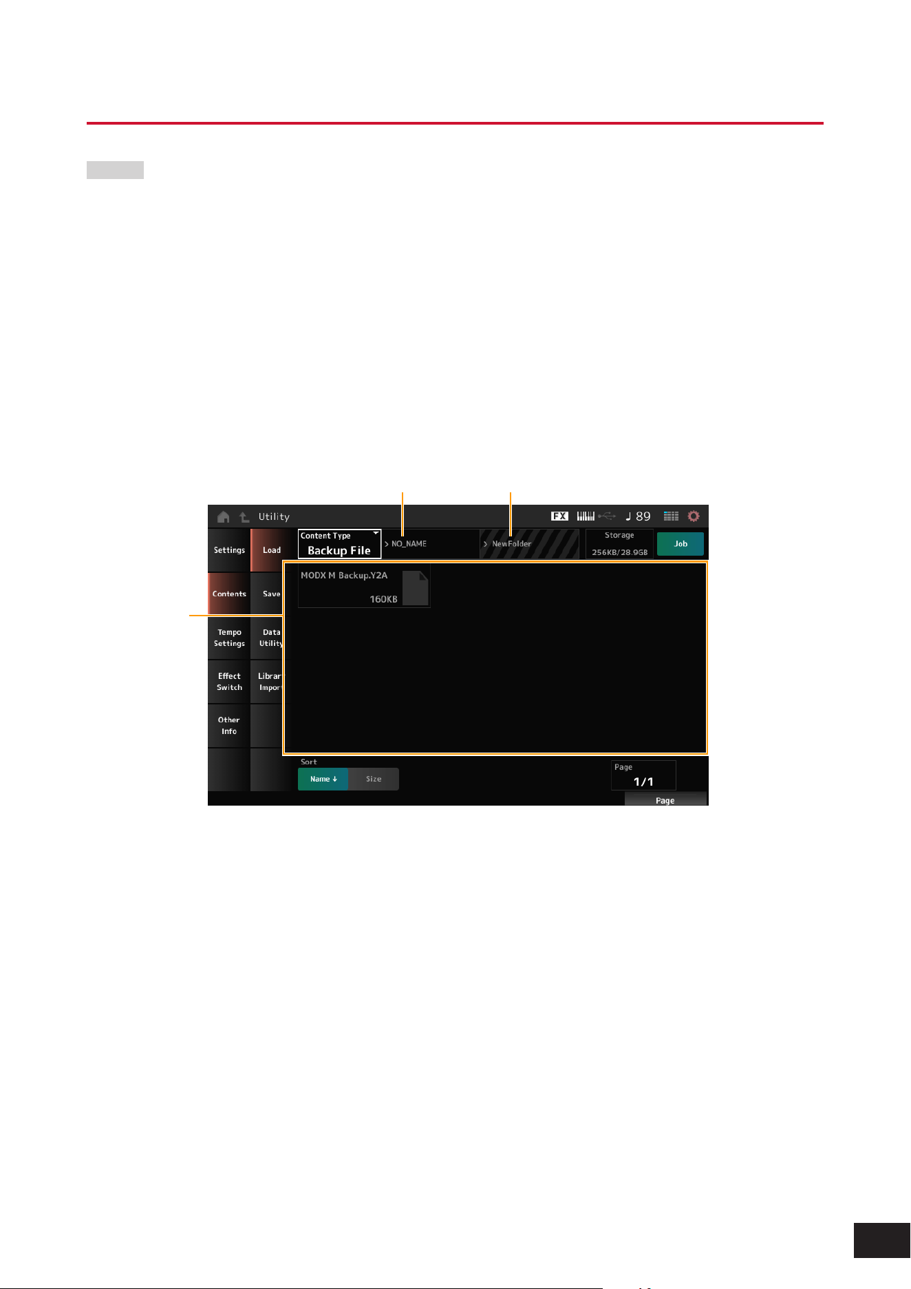
3.
Under Content Type, select Backup File.
4.
Select the desired source USB flash drive and folder that contains the settings.
5.
Select the desired file on the USB flash drive to load.
(1) (2)
(3)
(1) Parent folder name
(2) Name of desired folder currently selected in the USB flash drive
(3) List of files already saved in the folder
58
MODX M Operation Manual
5. Connecting external MIDI instruments
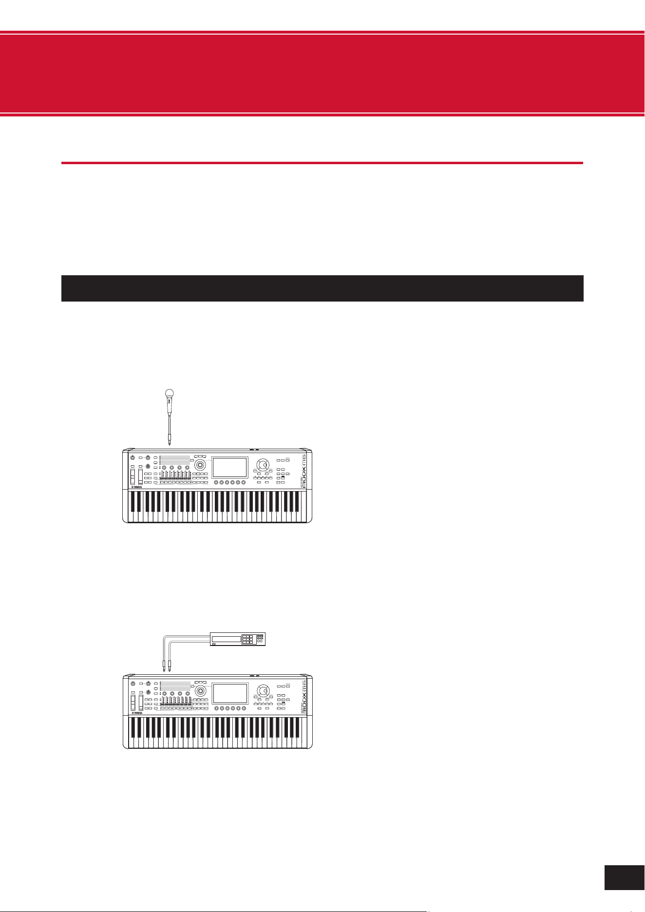
Connecting a microphone or audio device
This device allows you to connect audio devices such as microphones and CD players, as well as electronic musical
instruments such as synthesizers, to the A/D INPUT terminal and play the input audio as an audio input part (A/D INPUT
part).
As with other parts, you can set Volume, Pan, Effects, etc. The audio input part is mixed with other parts and output as
the sound of this instrument.
Connecting microphones and audio devices
1.
Make sure to turn off this instrument and set the A/D INPUT [GAIN] knob to the minimum value.
2.
Connect the external device to the A/D INPUT jack(s) on the rear panel.
When connecting a microphone
A/D INPUT [L/MONO]
Mic.
NOTE
Make sure to use a dynamic microphone. Condenser microphones cannot be used.
When connecting audio devices, electronic musical instruments, etc.
A/D INPUT [R ]A/D INPUT [L /MONO]
L
R
(1) Stereo audio equipment
(CD player, etc.)
(1) Stereo audio device (CD player, etc.)
3.
Turn on the connected device, and then turn on this instrument.
4.
Open the screen by going to [UTILITY]
→
Settings
→
Audio I/O.
59
MODX M Operation Manual
5.
Select the A/D Input setting for the device connected to the A/D INPUT jack(s).
Set to Mic when a microphone or any device with a low output level is connected. Set to Line when an audio device,
electronic instrument, or any device with a high input level is connected.
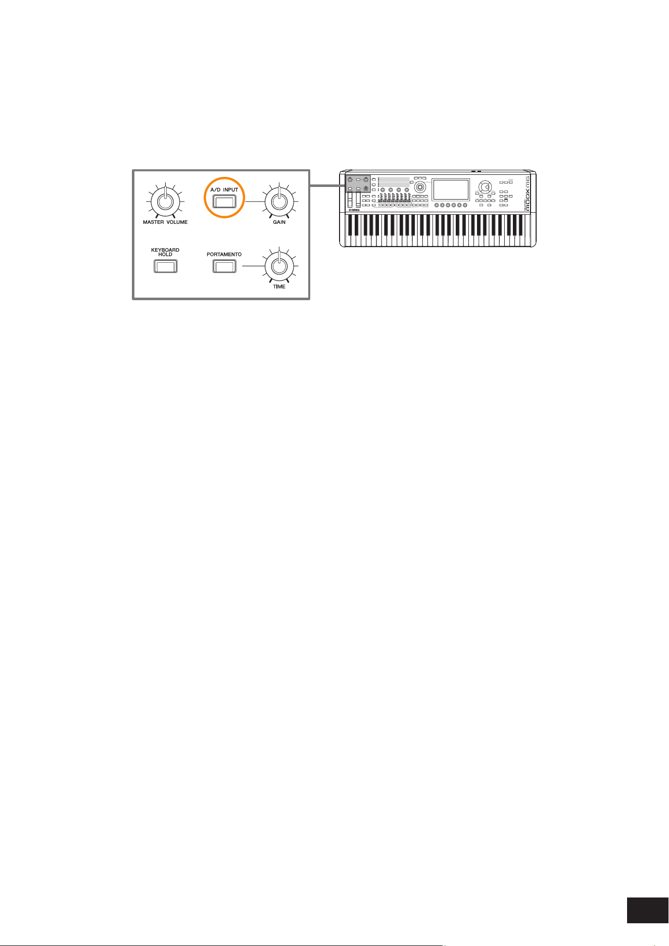
6.
Press the [A/D INPUT] button.
The button lights up and the input from the audio equipment connected to this instrument is enabled.
7.
Listen to the sound from the external device connected to the MODX M and turn the A/D INPUT
[GAIN] knob to adjust the gain.
8.
Press the [PERFORMANCE (HOME)] button and select the Performance you wish to use with the
external device connected to the MODX M.
9.
Play the keyboard while singing into the microphone or playing audio with the audio device.
Adjust the A/D INPUT volume on the Control sliders.
60
MODX M Operation Manual
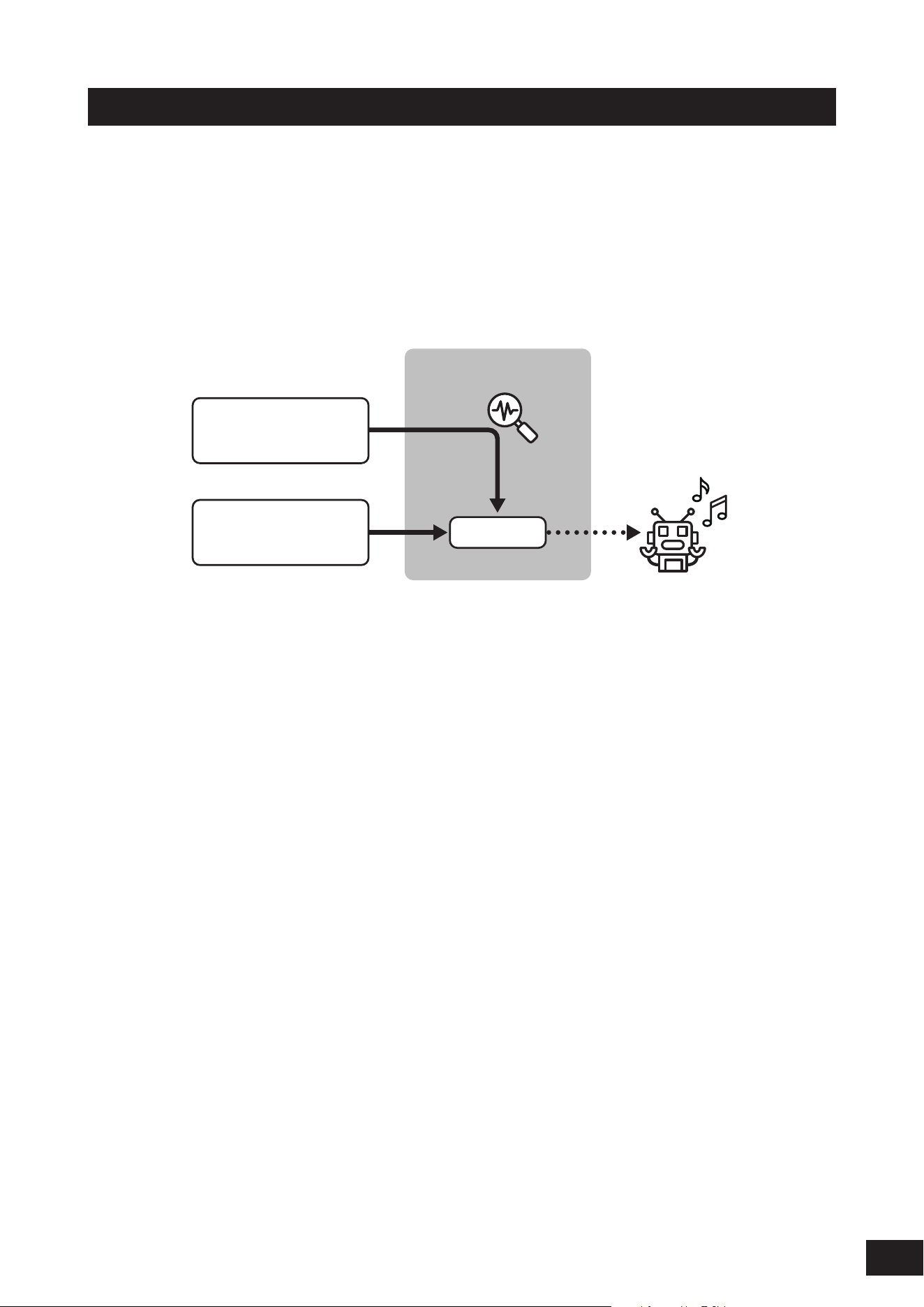
Using the Vocoder
This instrument is equipped with a Vocoder. The Vocoder is an effect that processes the sound of the internal sound
engine of this device using the characteristics of the voice input from the microphone. If you play the keyboard while
speaking into the microphone, the sound of the instrument will change to sound like a robot voice.
This mechanism is based on the principle of how humans make sounds. The sound produced by the vocal cords
resonates in the mouth and nose. The mouth and nose act like lters that enhance certain frequencies, creating formants
(peaks at specic frequencies) in the sound.
The Vocoder effect applies this principle by extracting the lter characteristics of the voice input from the microphone and
reproducing the formants with multiple bandpass lters. By passing the sound of musical instruments through it, a robot
voice effect is created.
Vocoder
(
3
)
(
5
)
(
1
)
Mic Input
Part Output
(
2
)
Part Output
(Keyboard Performance)
(
4
)
(1) Mic Input or Part Output
(2) Part Output (instrument output)
(3) Extracting voice characteristics
(4) Reproducing formants with filters
(5) Robot-like voice
To use the Vocoder, connect the microphone, set the A/D Input settings in the Utility screen, and adjust the gain. Finally,
select a Performance that uses the Vocoder effect, as shown below.
1.
On the Performance screen, press the [CATEGORY] button.
2.
Tap the button(s) on the screen to select the Pad/Choir category.
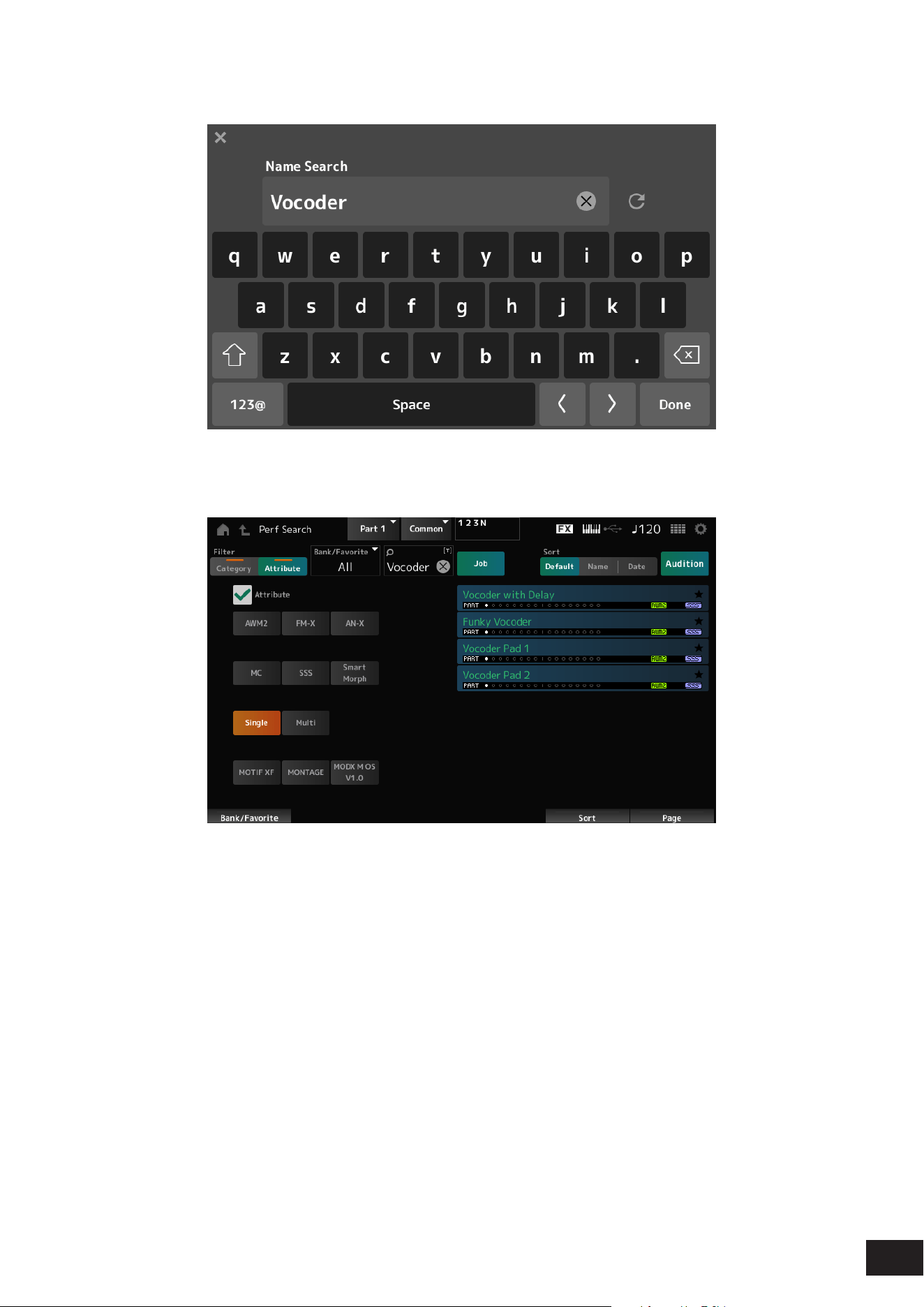
61
MODX M Operation Manual
3.
Tap the search box on the Category Search screen, and enter "Vocoder".
4.
Set Filter to Attribute and select Single.
A list of Performances for Vocoder effects will be shown.
5.
Select the desired Performance and press the [ENTER] button to confirm.
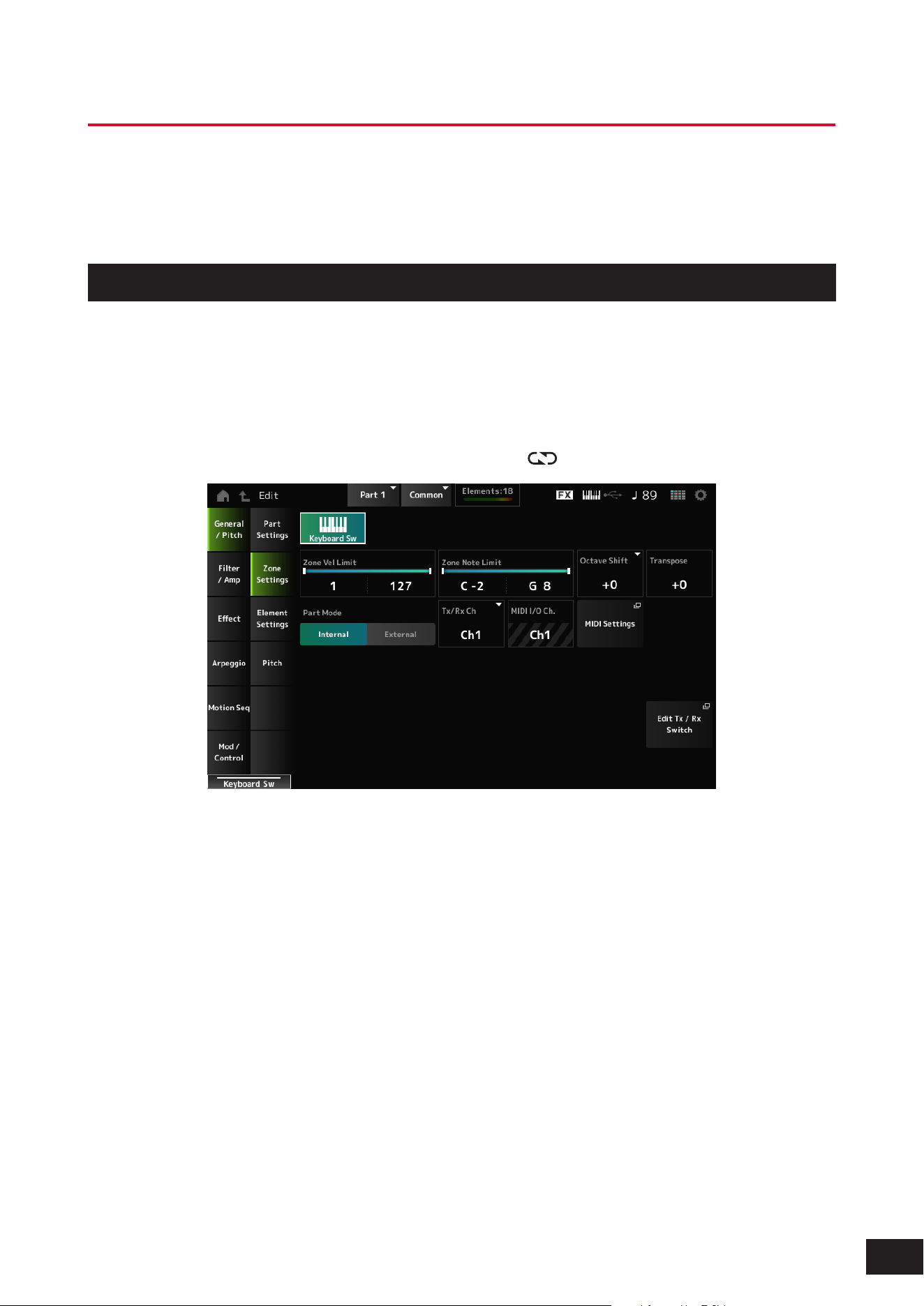
62
MODX M Operation Manual
Connecting to a Computer or External MIDI Device
The USB and MIDI terminals on the rear panel are used for connecting to a computer and external MIDI devices. You can
use these terminals to send Program Change messages to external MIDI devices when you change the Performance.
The Zone function is useful for setting up external MIDI devices.
Setting up the Zone function
The Zone function enables control of multiple external devices from the keyboard on this instrument.
You can set up to eight zones for each performance.
For example, you can use this function to switch between the internal sound engine and connected external sound
engines by velocity or note range.
1.
Press the [PERFORMANCE (HOME)] button to open the Performance screen.
2.
Select a part, then open the screen by selecting [EDIT/ ]
→
General/Pitch
→
Zone Settings.
3.
Check the Part Mode settings.
Select Internal to play the sound from the sound engine, and External to play the sound from the external sound
engine.
NOTE
You can toggle between Part Mode Internal and External by quickly pressing the PART button twice when the [PART SELECT]
button is on.
4.
If necessary, set the parameters for Tx/Rx Ch (Transmit-Receive Channel) and Note Limit.
5.
Press the [STORE] button to save the Performance.
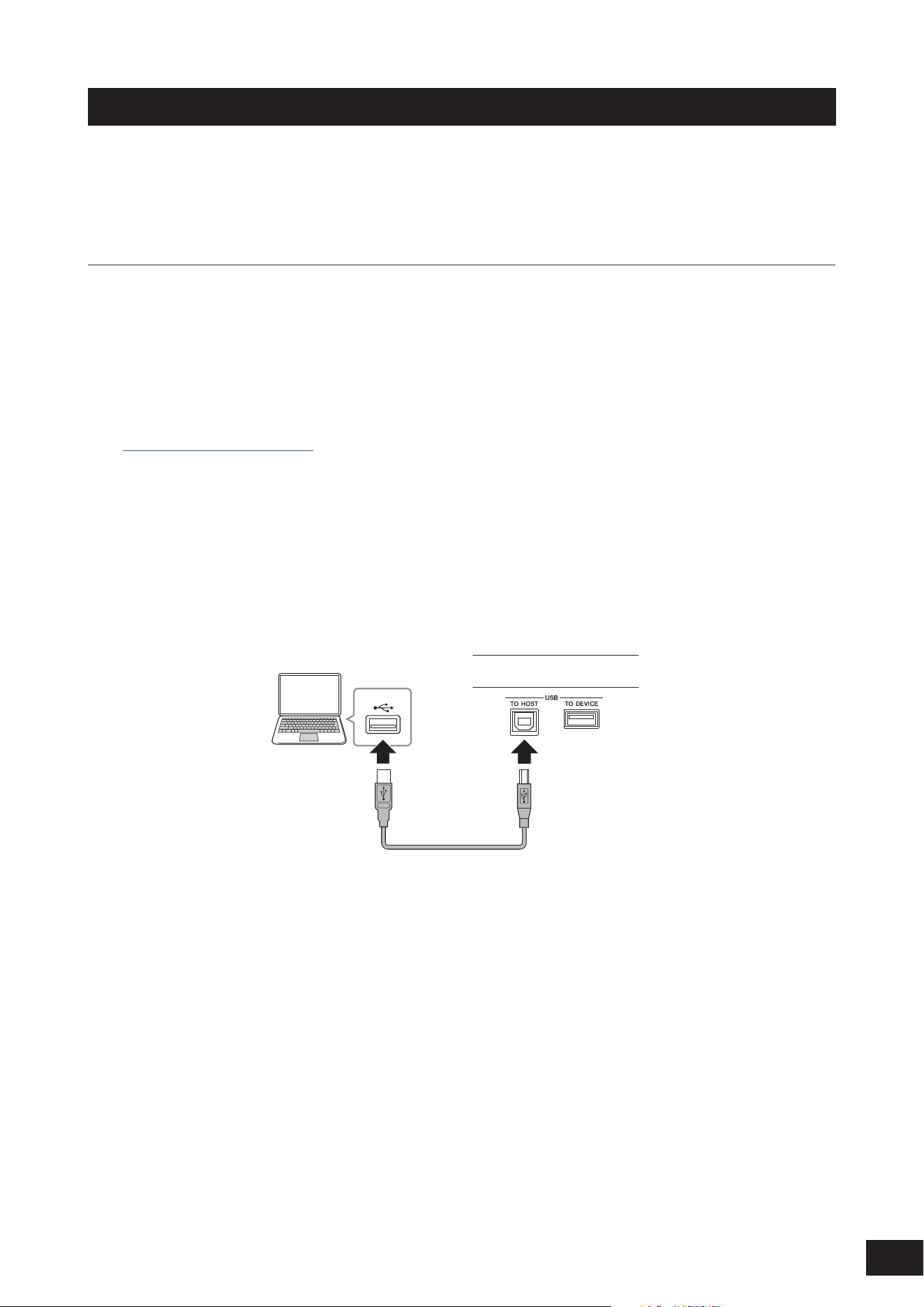
63
MODX M Operation Manual
Connecting and setting up a computer
By connecting your computer to this instrument, you can use a DAW or sequencer software on the computer to create
your own music.
The acronym DAW (digital audio workstation) refers to music software for recording, editing, and mixing audio and MIDI.
Typical DAW software includes Cubase, Logic, ProTools, and Live.
Connecting a computer and setting up
By connecting a computer to the USB [TO HOST] terminal, you can send and receive audio signals and MIDI messages.
An AB-type USB cable and the driver for sending and receiving audio and MIDI are required for the connection.
In Windows you must install the Yamaha Steinberg USB Driver. On a Mac, it works with only the generic driver included
in the OS, so no driver installation is required.
How to Install the Yamaha Steinberg USB Driver
1.
Download the latest driver from the URL shown below.
https://download.yamaha.com/
NOTE
• Information on the system requirements is also available at the above URL.
• The Yamaha Steinberg USB Driver may be updated without prior notice for improvement purposes. For more details and the
latest information, please check the URL above.
2.
Unzip the downloaded file and install the Yamaha Steinberg USB Driver on your computer.
For instructions on how to install the driver, refer to the Installation Guide included in the downloaded file.
When connecting this instrument to a computer, use a USB cable to connect the USB [TO HOST] terminal to the
computer's USB terminal as shown in the diagram below.
(1) USB terminal (3) USB [TO HOST] terminal
(2) USB cable
(4) MODX M
(Rear panel)
(1) USB terminal
(2) USB cable
(3) USB [TO HOST] terminal
(4) Rear panel of this instrument

64
MODX M Operation Manual
Setting up for sending and receiving audio and MIDI
Connect the computer with a USB cable, and then set the parameters for handling audio and MIDI through the USB
connection.
• Audio
Can be used by simply connecting the USB cable. And, if necessary, change settings such as sampling frequency and
gain.
• MIDI
Connect the cable and then set the parameters for transmitting and receiving. Please follow the steps below to set it up.
Open the screen from the [UTILITY]
→
Settings
→
MIDI I/O
→
MIDI IN/OUT and select USB.
Set this instrument to enable the transmission and reception of MIDI through the USB [TO HOST] terminal.
About audio channels
For the output of audio signals, you can use the USB [TO HOST] terminal and the OUTPUT jacks. The audio signal output
to the USB [TO HOST] terminal is up to 10 channels (5 stereo channels) at a sampling frequency of 44.1 kHz.
To select which signal to output to a specific channel, open the screen from the [PERFORMANCE (HOME)]
→
Part
selection
→
[EDIT/
]
→
General/Pitch
→
Part Settings, and select the appropriate Part Output.
For the input of audio signals, you can use the USB [TO HOST] terminal and A/D INPUT jacks.
Audio signals coming in through the USB [TO HOST] terminal can contain up to 4 channels (or 2 stereo channels), and
the output levels for Digital In L/R and Main L/R are set on the Mixing screen or Performance Edit screen, and are output
to the OUTPUT terminals.
In addition, the audio signal from the A/D INPUT terminal is sent to the A/D input section of this instrument on up to two
channels (one stereo channel).
MIDI channels and MIDI ports
MIDI has 16 channels, but for large song data, 16 channels may insufficient.
Therefore, the concept of MIDI ports exists to handle data with more than 16 channels. Each MIDI port can handle 16
channels.
• One MIDI cable can transmit data for one port (16 channels) at a time.
• However, a single USB cable is capable of handling MIDI data for up to 8 ports (or 16×8=128 channels) simultaneously.
On this instrument, the determined ports are provided for the USB terminals, as shown below.
Port 1: Port for handling the sound engine section of this instrument
Make sure to set to Port 1 on the external MIDI device or the computer, if you wish the sound engine to be played on the
external MIDI device or the computer.
Port 2: Dedicated for using the DAW remote control.
Port 3: Dedicated for receiving MIDI messages from a MIDI device and sending them to another MIDI device
for MIDI Thru.
• MIDI port 3 data received by the USB [TO HOST] terminal is passed through the MIDI [OUT] terminal.
• MIDI data received by the MIDI [IN] terminal is passed through the USB [TO HOST] terminal as MIDI port 3 data.
For sending MIDI messages between the instrument and the computer through the USB cable, you need to select the
appropriate MIDI Port as well as the MIDI channel. Set the Port settings on the external device suitable for the situation.
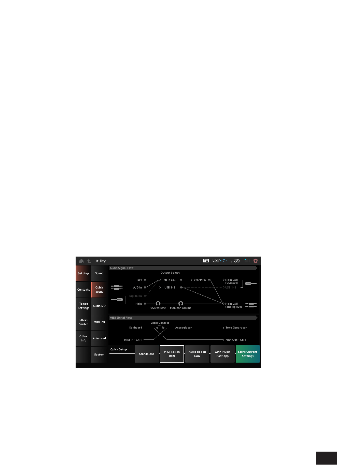
65
MODX M Operation Manual
Using the MIDI 2.0 functions
This instrument supports MIDI 2.0 functionality. By connecting this instrument to a computer that meets the MIDI 2.0
operational requirements, you can use data of higher resolution than that of any MIDI 1.0 instrument.
For more information about MIDI 2.0, see the MIDI 2.0 site (https://www.yamaha.com/2/midi-2-0/).
For details on the supported MIDI 2.0 messages, refer to the Data List.
https://download.yamaha.com/
To use the MIDI 2.0 functionality, first access the setting from [UTILITY]
→
Settings
→
Advance
→
USB Driver Mode and
set Legacy Mode to Off, then connect a computer that meets the MIDI 2.0 operating requirements.
About music production using the computer
By connecting this instrument and the computer, you can use the DAW software as in the examples shown below.
• Using the DAW software on the computer to record your keyboard performance in MIDI or audio
• Using the tone generator block to play back the Song recorded on the DAW software
These instructions assume that the instrument and the computer are already connected. Shown below are some
examples of using the DAW software and this instrument.
MIDI recording of your keyboard performance on the DAW
This shows how to record your keyboard performance on the DAW as MIDI data.
Settings on this instrument
1.
Open the screen by going to [UTILITY]
→
Settings
→
Quick Setup.
2.
Select MIDI Rec on DAW.
3.
Press the [EXIT] button to close the Quick Setup screen, or press the [PERFORMANCE (HOME)]
button to open the Performance screen and select the Performance you want to record.
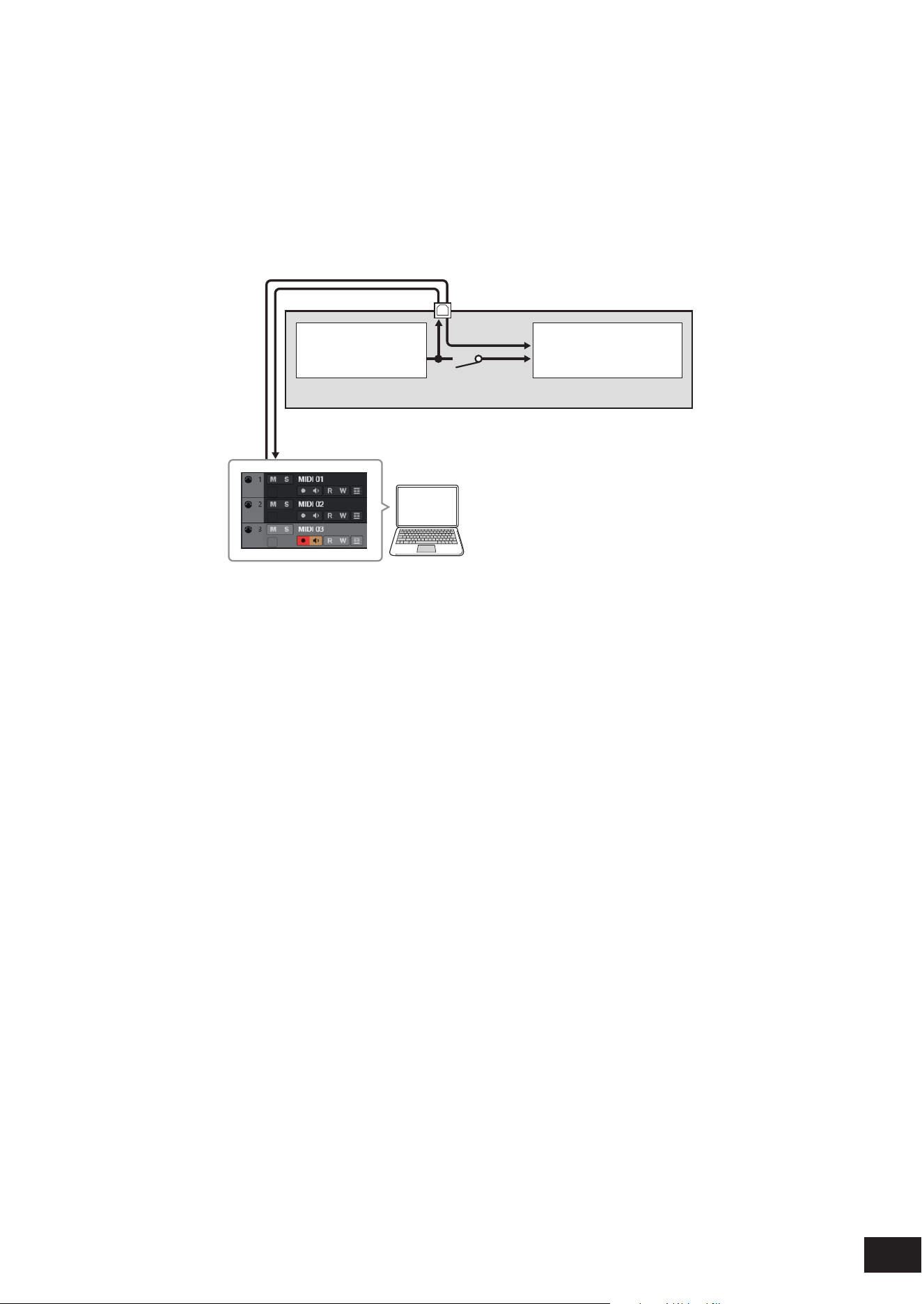
66
MODX M Operation Manual
The setting on the DAW software
1.
Enable MIDI Thru.
MIDI Thru is a setting used for sending MIDI messages from the built-in keyboard to the computer and back to the
Tone generator block of the instrument according to the settings on the recording tracks.
As shown below, for example, the MIDI data entered from this instrument is sent to Channel 1. If MIDI Thru is set to
ON on the computer, then the MIDI data is sent to Channel 3 from the computer to play the sound engine at Channel
3. By using this setup, you can record the keyboard performance while listening to the same sound as the final
output.
MODX M
USB [TO HOST] terminal
(1) Tone Generator
(recognizing data
over MIDI Channel 3)
(2) Keyboard
(output via
MIDI Channel 1)
MIDI Thru = on
IN
Ch1
OUT
Ch3
(3) Local Control = off
(4) Computer
(DAW software such as Cubase)
(1) Tone generator block (recognizing data over MIDI Channel 3)
(2) Keyboard (Ch1)
(3) Local Control = OFF
(4) Computer (DAW software such as Cubase)
2.
Record the instrument performance on the DAW.
Using the sound engine to play back Songs on the DAW
This shows how to use the DAW software as a Multi-timbral sound generator.
It allows you to use the high-quality MIDI sound generator without placing too much load on your computer’s CPU.
Settings on this instrument
1.
Select a Performance.
After selecting a Performance, you may find it helpful to use the Mixing screen from: the [PERFORMANCE (HOME)]
→
Mixing to mix Part 1 to 16.
From the [UTILITY]
→
Effect Switch screen, set Kbd Ctrl Lock to ON to set the Tx/Rx Ch. of each Part to enable the
reception of messages.
The setting on the DAW software
1.
With the tracks you wish to use for playing the sound engine, set the MIDI output to Port 1 on this
instrument.
2.
Enter the MIDI data for each track.
The sound engine corresponding to each track's MIDI channel is set on the Mixing screen of this instrument.

67
MODX M Operation Manual
Using Expanded Softsynth Plugin for MONTAGE M/MODX M
Expanded Softsynth Plugin for MONTAGE M/MODX M is a software synthesizer with the same sound engine system as
the hardware MONTAGE M and MODX M.
Since this software works in sync with the hardware MONTAGE M or MODX M, the same sounds can be seamlessly
integrated into your music production (where software is most convenient for a DAW), and into your live performance
(where the actual instrument is used onstage). This lets you use either version of the MONTAGE M or MODX M,
depending on your personal preferences and specific application.
For more information on the installation and activation of the ESP, access the MODX M Welcome page from the Expanded
Softsynth Plugin for MONTAGE M/MODX M Download Information leaflet included with the instrument.
ESP Manual can be downloaded from the website below.
https://download.yamaha.com/
Using the DAW Remote function
The DAW Remote function allows you to control the DAW software from the controllers on the top panel of this instrument.
This function can only be used when the instrument is connected to a computer with an USB cable. It cannot be used
when connected with a MIDI cable.
Settings on this instrument
1.
Use an AB-type USB cable to connect a computer to the USB [TO HOST] terminal of the
instrument.
2.
Select the DAW software from: [DAW REMOTE]
→
Settings
→
DAW.
The setting on the DAW software
This section explains how to set up the DAW software.
Depending on the version of your DAW software, the setup procedure may be different or the setup itself may not be
possible. For details, please refer to the relevant owner’s manual for the DAW software you are using.
NOTE
Once the connection between the computer and this instrument is lost, the DAW software may not recognize this instrument even after
reconnection. If this happens, restart the DAW after the reconnection.
• Cubase
1. Device/Studio
→
Device Settings.../Studio Setup... to open the dialog box.
2. Select MIDI
→
MIDI Port settings, and uncheck All MIDI Input for Port 2 of MODX M-2 or MODX M.
3. Press the [+] button on the upper left corner of the dialog, and then select Mackie Control from the list.
4. Select Remote Devices
→
Mackie Control.
5. Set the MIDI Input and MIDI Output to MODX M-2 or MODX M Port2.
6. (Optional) Assign desired functions to F1–F8 of User Commands.
• Logic Pro
1. Select Logic Pro X
→
Preferences
→
Advanced
→
and check Show [Advanced Tools].
2. Logic Pro X
→
Control Surfaces
→
Setup... to open the dialog box.
3. From New
→
Install..., select Mackie Designs from Mackie Control.
4. Set the Output Port and the Input Port of Mackie Controlto MODX M Port2.
5. (Optional) From Logic Pro X
→
Control Surface
→
Controller Assignments... set the Zone to Control Surface: Mackie
Control, then assign functions to Control F1–F8.

68
MODX M Operation Manual
• Pro Tools
1. Setup
→
Peripherals... to open the dialog box.
2. Select the MIDI Controllers tab.
3. Set the Type to HUI and the Receive From and Send To to the predefined ones (Predefined) MODX M-2 or MODX M,
Port2.
• Live
1. Live
→
Preferences... to open the dialog box.
2. Select the Link/MIDI tab.
3. Select MackieControl for the Control Surface.
4. Set the MIDI Input and MIDI Output to MODX M-2 or MODX M Port2.
5. (Optional) Assign desired functions to F1–F8 by setting the operation of MIDI Note F#2–C#3 in the MIDI Map Assign
Mode.

69
MODX M Operation Manual
Connecting a smart device
You connect a smart device such as a smartphone and a tablet to this instrument.
Smart device apps that are compatible with this instrument provide many more convenient and enjoyable ways to use this
musical instrument.
For more information on the apps and supported devices, refer to the Yamaha website.
For details on how to connect, search for "Smart Device Connection Manual" on the Yamaha website.
To use audio communication with an iOS device, please prepare the following adapters according to the type of
connector/terminal.
• Lighting Terminals: Lightning to USB 3 Camera Adapter
• USB Type-C port: USB-C Digital AV Multiport Adapter
When connecting a smart device, on the instrument go to [UTILITY]
→
Settings
→
USB Driver Mode and set it to Generic.
Connecting External MIDI Instruments
Using USB cables and standard MIDI cables (that are commercially available), you can connect an external MIDI
instrument to this instrument.
You can play an external MIDI instrument from the built-in keyboard, or play the tone generator block from an external
MIDI keyboard or sequencer.
NOTE
You can use either the USB [TO DEVICE] terminal or the MIDI terminal to connect the external MIDI device.
Connecting an external MIDI device to MIDI terminals
When using MIDI terminals, connect an external MIDI device with MIDI cables, and then select MIDI from [UTILITY]
→
Settings
→
MIDI I/O.
Controlling an external MIDI sound engine with this instrument
You can play sounds from an external MIDI sound engine using the keyboard on this instrument or by song playback.
To play the sounds from the internal sound engine and external MIDI sound engine separately, use the Zone function.
Make sure to match the MIDI Transmit Channel of the external MIDI device with the MIDI Receive Channel of the
instrument.
Setting the MIDI receive channel for this instrument
The MIDI output channel on this instrument should be set to a different value, depending on whether there are any Parts
with Part Mode set to External.
• If Part Mode does not have any External Parts
Parts with Common or Keyboard Control Switch set to ON: MIDI I/O Ch.
Parts with Keyboard Control Switch set to OFF: Tx/Rx Ch.
• If Part Mode does have External Parts
Parts with Common or Keyboard Control Switch set to ON: Tx Ch. for which the Part Mode is set to External and
Keyboard Control Switch is set to ON
Parts with Keyboard Control Switch set to OFF: Part Mode is set to External and other Part's Tx Ch.
*Any Parts with Part Mode set to Internal will not transmit MIDI messages.
Setting the receive channel for an external MIDI sound engine
Please refer to the instruction manual for the external MIDI sound engine.
When you wish to play the sound only from the external sound engine, lower the volume on this instrument, or set Local
Control to OFF from [UTILITY]
→
Settings
→
MIDI I/O.

70
MODX M Operation Manual
Playing the sounds of this instrument with an external MIDI keyboard
You can use the keys on an external MIDI keyboard to play this instrument's Performances and change Performances.
Make sure to match the MIDI Transmit Channel of the external MIDI device with the MIDI Receive Channel of the MODX
M.
Setting the MIDI receive channel for this instrument
Parts with Keyboard Control Switch set to ON: MIDI I/O Ch.
Parts with Keyboard Control Switch set to OFF: Tx/Rx Ch.
* If the Part Mode is set to External, the Part will not receive MIDI messages from the external device.
Setting the transmit channel for an external MIDI keyboard
Please refer to the Owner's Manual for your external MIDI keyboard.
Connecting a USB MIDI keyboard to the USB [TO DEVICE] terminal
By connecting a USB MIDI keyboard to the USB [TO DEVICE] terminal, you can use the connected keyboard just like the
built-in keyboard, depending on the functions of the connected USB MIDI keyboard.
NOTICE
• The rating of the USB [TO DEVICE] terminal is a maximum of 5 V/500 mA. Do not connect USB devices having a rating above
this, since this can cause damage to the instrument itself.
• Use an AB-type USB cable of less than 3 meters.
Compatible MIDI devices
• USB class-compliant MIDI devices
USB MIDI keyboard, etc.
• Yamaha MIDI devices that have been tested for compatibility
CP88, CP73, MODX, MODX+, MONTAGE, MOTIF XF, MOXF, MX, reface, YC, MONTAGE M, SEQTRAK
Special notes concerning MIDI communication
MIDI communication with a device connected via the USB [TO DEVICE] terminal follows special rules for allowing the
device to behave like a built-in keyboard.
• MIDI communication is one-way only (sent from the external MIDI device and received by this instrument).
• All MIDI data is received regardless of the MIDI IN/OUT and MIDI I/O Ch. settings.
• For Parts with Keyboard Control Switch set to ON, data received on all corresponding channels is shared.
(For example, when Keyboard Control Switch for Parts 1 to 3 is set to ON, data received from any of channels 1 to 3 will
be delivered to all Parts 1 to 3.)
• Each Part with Keyboard Control Switch set to OFF receives the data of only the corresponding channel for the Part.
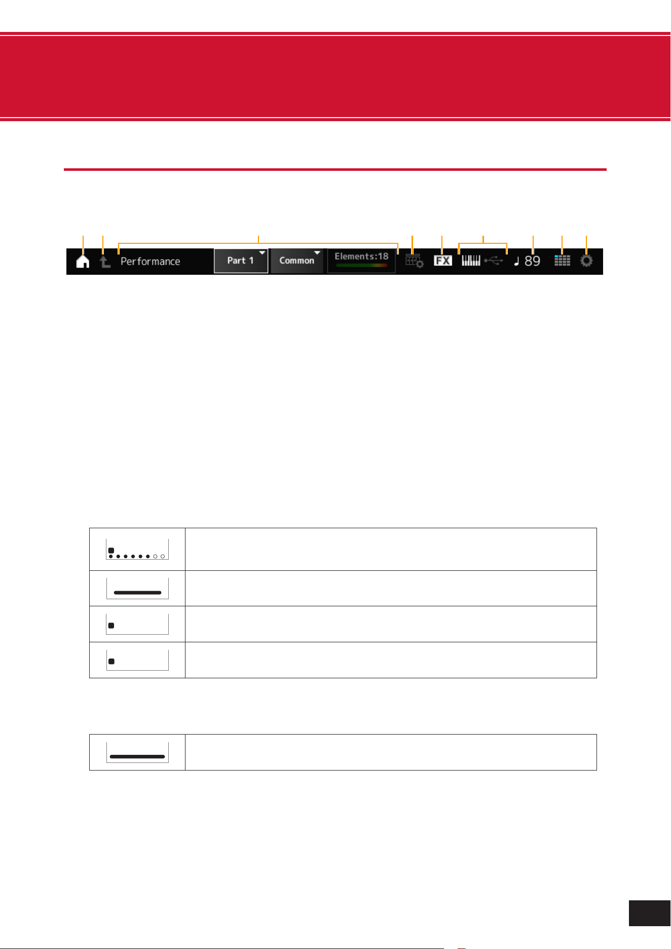
71
MODX M Operation Manual
6. Screens and parameters
Navigation bar
This chapter explains the Navigation bar, which is always displayed on the screen.
(3)
(1)
(2) (4) (5) (7) (8) (9)
(6)
(1) HOME icon
This has the same function as the [PERFORMANCE (HOME)] button on the top panel. Tap to display the Performance
screen (HOME).
(2) EXIT icon
This has the same function as the [EXIT] button on the top panel. Tap to return to the screen one level higher.
(3) INFORMATION area
This area displays information such as the currently selected screen name, part, element, operator, oscillator, and
drum key.
Tap
to switch parts, elements, operators, oscillators, and drum keys.
• Normal Part
When a Normal Part is selected, the status of the elements, operators and oscillators is displayed on the right side
of this area.
When muted, an M icon appears below the number.
1 2 3 4 5 6 7 8
M S
Element (AWM2)
When an element is sounding, the
below the number lights up to
. When dividing elements
according to velocity, you can check which element is being played.
Elements: 18
The total number of set elements
The indicator shows the volume of the element being played
1 2 3 4 5 6 7 8
M S
Operator (FM-X)
1 2 3 N
M S
Oscillator (AN-X)
• Drum Part
When a Drum Part is selected, the status of the drum key is displayed on the right side of this area.
Drum Keys: 73
The total number of set drum keys
The indicator shows the volume of the drum part being played
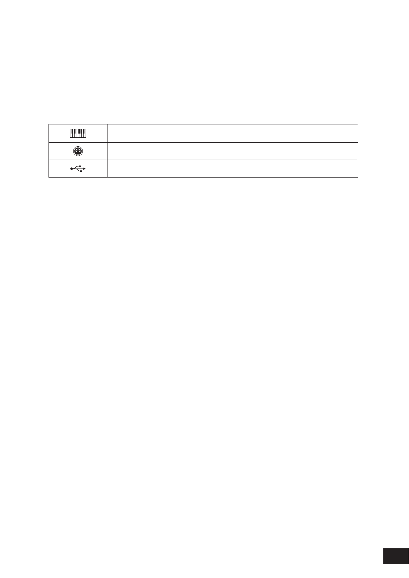
72
MODX M Operation Manual
(4) VIEW icon
This function allows you to select the view on the Performance screen. Tap to display the view list on the Performance
screen.
(5) EFFECT icon
Tap to display the Effect Switch screen. When the Insertion Effect, System Effect, or Master Effect is turned Off, the
indicator turns off.
(6) QUICK SETUP icon
Tap to display the MIDI I/O screen.
Displays on or off for Local Control
On when the icon is on, Off when it is off.
Displayed when MIDI IN/OUT is set to MIDI
Displayed when MIDI IN/OUT is set to USB
(7) TEMPO SETTINGS icon
Displays the tempo of the currently selected Performance. Tap to display the Tempo Settings screen.
(8) LIVE SET icon
Tap to display the Live Set screen.
The currently selected slot is displayed in blue.
(9) UTILITY icon
Tap to display the most recently opened Utility screen.
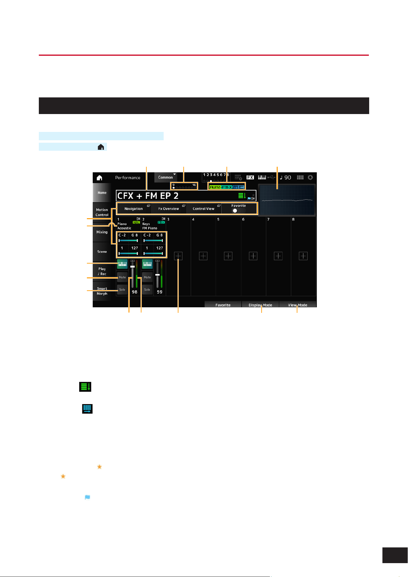
73
MODX M Operation Manual
Performance Screens
The Performance screen lets you select a Performance for playing on the keyboard or modify the Performance settings
to customize the Performance.
HOME
Operation
Press the [PERFORMANCE (HOME)] button
Tap the HOME icon (
)
(1) (2) (3)
(14)
(13)
(4)
(11) (12)
(5)
(6)
(7)
(8)
(9)
(10)
(1) Performance Name
Shows the name of the selected Performance. Tap to display the context menu for Category Search, Edit, Recall, etc.
You can switch Performances using the Data dial, the [INC/YES] button, and the [DEC/NO] button. There are two ways
to switch.
• Default (
)
Switches in the order of the Performance list on the Performance Category Search screen.
• Live Set (
)
Switches in the order of the Live Set slots.
You can set the switching method from [UTILITY]
→
Settings
→
System
→
Perf Inc/Dec.
You can check the status of the Performance with the ags.
• Favorite Flag (
)
A
will be shown when you turn on the Favorite switch. It will also be displayed on the Performance Category
Search screen.
• Edit Flag (
)
The blue ag will be shown when you change a parameter in the Performance. The Edit ag will be turned off when
you save the settings with the [STORE] button.

74
MODX M Operation Manual
(2) Performance Flag
The Performance ags are displayed.
Attribute Description
AWM2
A Performance consisting only of AWM2 sound engine parts
FM-X (1 color)
A Performance consisting only of FM-X sound engine parts
FM-X (2 colors)
Performances using an FM-X Part containing the Smart Morph
information
AN-X (1 color)
Performances using the AN-X sound engine
AN-X (2 colors)
A Performance using an AN-X Part containing the Smart Morph
information
MC
Performances featuring Motion Control
SSS
A Performance that supports Seamless Sound Switching
* Performances that combine multiple sound engine types are indicated with the “+” sign.
(3) Oscilloscope
The Main L&R output is displayed as a waveform.
(4) Part Indicator
When the cursor is on either Performance Name or Parts 1 to 8, the status for Parts 9 to 16 will be shown.
When the cursor is on Parts 9 to 16, the status for Parts 1 to 8 will be shown.
Nothing will be shown when Parts 9 to 16 are not used.
(5) View area for various parameters
Different parameters will be shown in this view area depending on the Display Mode.
(6) Part Name
Part Type and Category, or Part Name will be shown.
Tap to display the context menu for Category Search, Edit, Copy, and Property.
When a Part other than Part 1 is selected and the sound is already set for that Part, the context menu for Category
Search, Edit, Copy, and Delete is displayed.
(7) Keyboard Control Switch
You can set which Parts will play simultaneously by turning each Part's Keyboard Control Switch on or off.
If the Part is set to Common or the Keyboard Control Switch for the Part is set to On, you can simultaneously play Parts
having the Keyboard Control Switch set to On.
If the Keyboard Control Switch for the Part is set to Off, when you play the keyboard with that Part selected, those
sounds will be played.
Settings: Off, On
(8) Part Mute
Switches Part Mute on or off.
Settings: Off, On
(9) Part Solo
Switches Part Solo on or off.
Settings: Off, On
(10) Part Volume
Sets the volume of the Part.
Settings: 0–127
(11) Part Level Meter
Shows the audio output level for the Part.
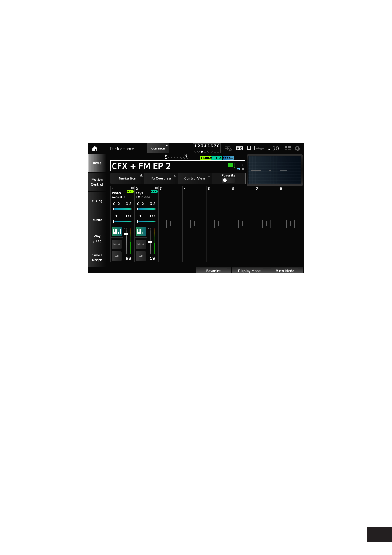
75
MODX M Operation Manual
(12) [+] (Add)
Tap to display the Part Category Search screen or Performance Merge screen, which allows you to add a Part.
(13) Changing the Display Mode
(14) Changing the View Mode
Changing the Display Mode
When you change the Display Mode, different parameters will be shown in the view area of the Home screen.
You can select a different Display Mode by moving the corresponding display knob.
Range
Navigation
The Navigation screen will open.
Fx Overview
The FX Overview screen will open.
Control View
The Control View screen will open.
Favorite
Turns the Favorite switch on or off.
Settings: Off, On
Note Limit
Sets the note range (the lowest and the highest notes) for the Part.
When the rst note specied is higher than the second (for example, C5 to C4), the notes in the ranges C−2 to C4 and C5
to G8 will be played.
Settings: C−2–G8
Velocity Limit
Sets the velocity range for the Part.
Settings: 1–127
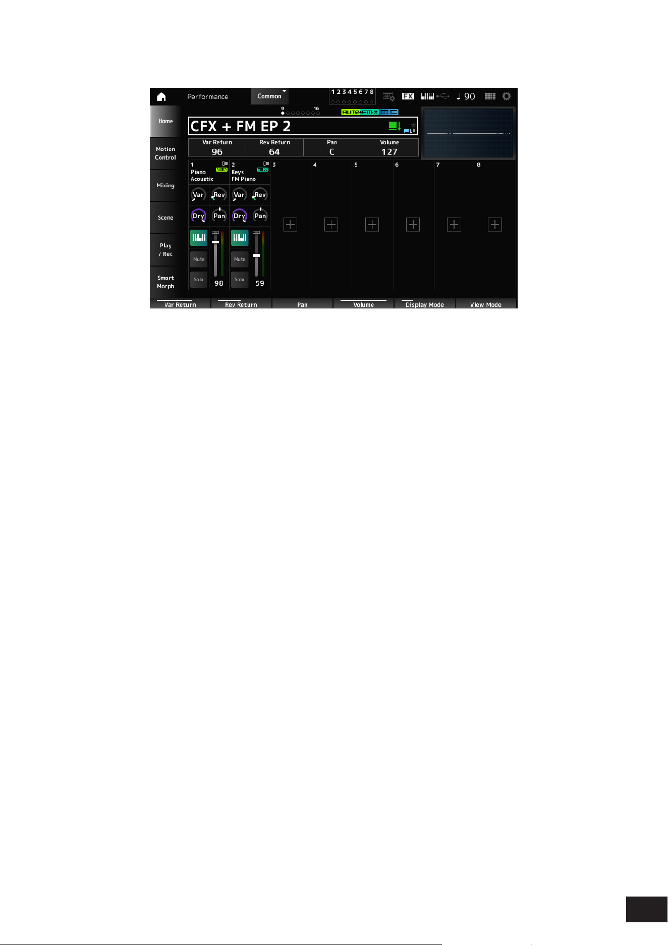
76
MODX M Operation Manual
FX/Pan
Var Return
Sets the output level (Return Level) of the signals processed by the Variation Effect.
Settings: 0–127
Rev Return
Sets the output level (Return Level) of the signals processed by the Reverb Effect.
Settings: 0–127
Pan
Adjusts the Pan position (stereo position) of the currently selected Performance.
Settings: L63–C (center)–R63
Volume
Adjusts the volume of the currently selected Performance.
Settings: 0–127
Var (Part Variation Send)
Sets the level of the signals sent to the Part Variation Effect.
Settings: 0–127
Rev (Part Reverb Send)
Sets the level of the signals sent to the Part Reverb Effect.
Settings: 0–127
Dry (Part Dry Level)
Sets the dry level (or the level of the signals not processed by the System Effect) of the Part.
Settings: 0–127
Pan (Part Pan)
Adjusts the Pan position (in the stereo eld) for the Part.
Settings: L63–C (center)–R63
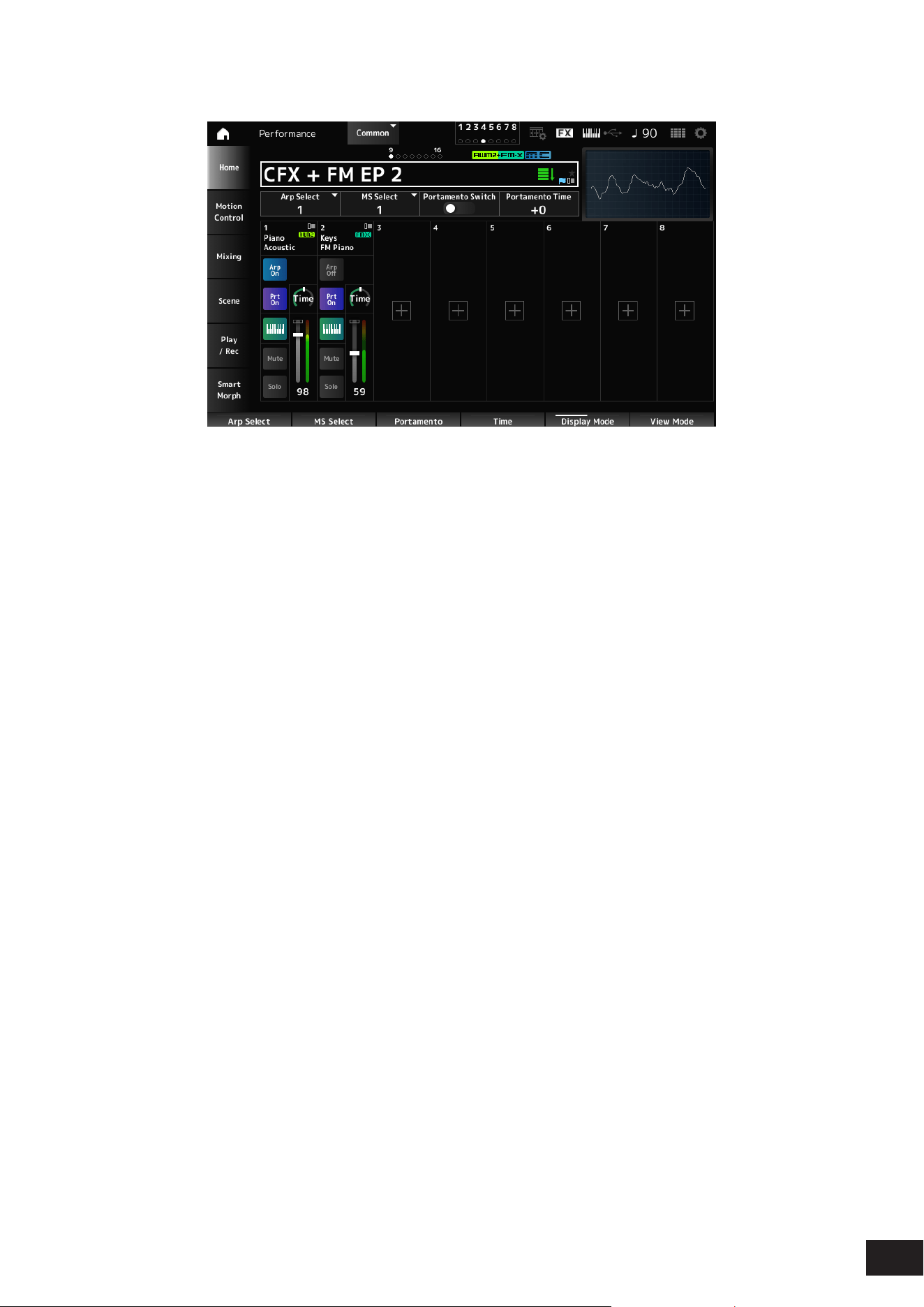
77
MODX M Operation Manual
Arp/MS/Porta
Arp Select
Selects the Arpeggio.
Settings: 1–8
MS Select
Changes the Motion Sequence selection.
Settings: 1–8
Portamento Switch
Sets Portamento on or off for Parts having the Portamento Part Sw set to On.
This switch is linked to the [PORTAMENTO] button on the top panel.
Settings: Off, On
Portamento Time
Sets the time length (or speed) for the pitch transition of Portamento for the Part.
This is the offset value for the Part's Portamento Time (the value adjusted relative to the reference).
Settings: −64–+0–+63
Arp On/Off (Arpeggio Part Switch)
Sets the Arpeggio on or off for the Part.
When both Arpeggio and Arpeggio Hold are On, Arp Hold On will be displayed.
When the Arpeggio is set to On, you can switch Arp Hold On or Off by simultaneously holding down the [SHIFT] button
and tapping the Arp On/Off button on the screen.
Settings: Off, On
MS On/Off (Motion Sequencer Part Switch)
Sets Motion Sequencer for the Part on or off.
Settings: Off, On
Prt On/Off (Portamento Part Switch)
Sets Portamento for the Part on or off.
Settings: Off, On
Time (Portamento Part Time)
Sets the time length of the pitch transition for the Portamento of the Part.
Settings: 0–127
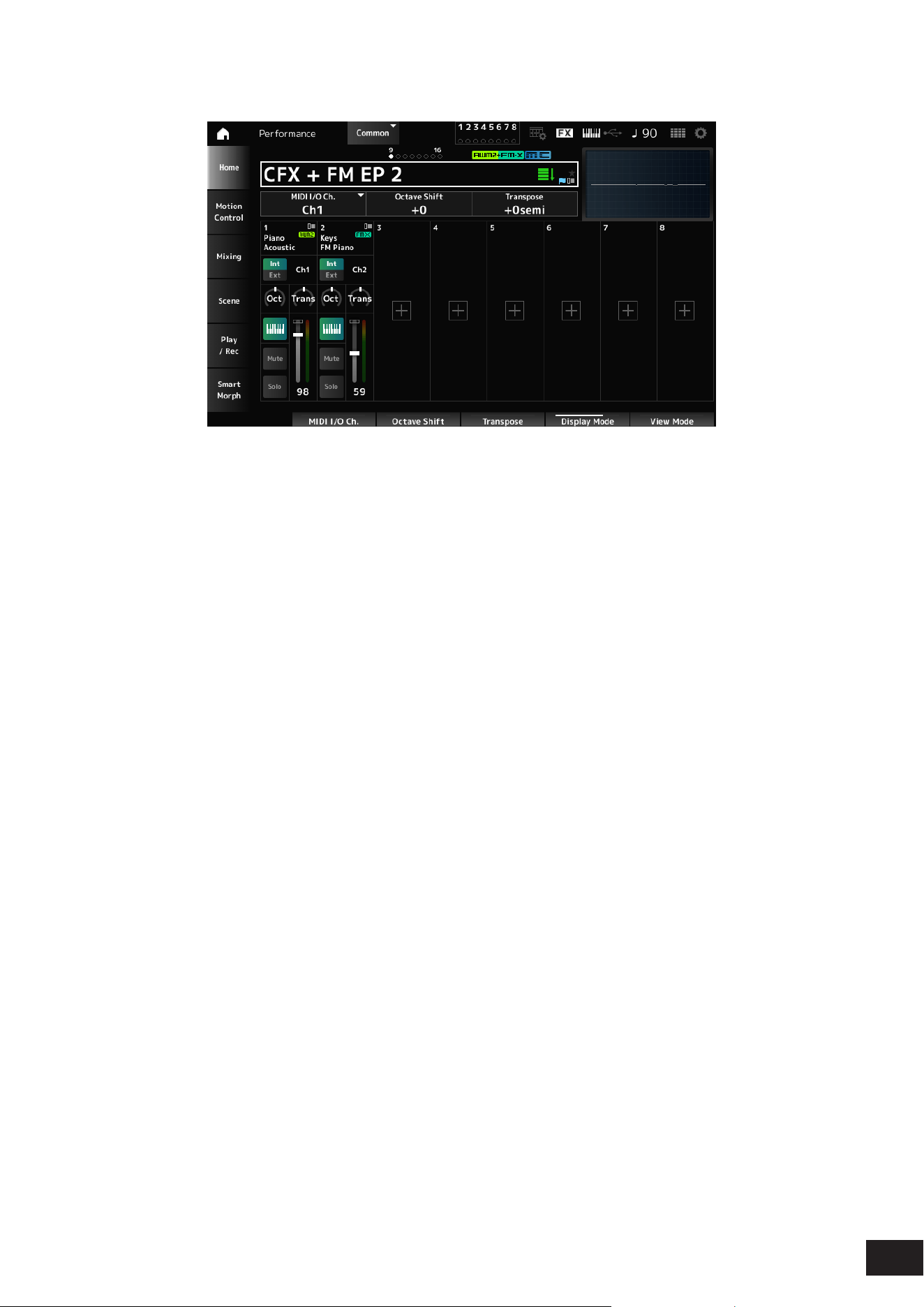
78
MODX M Operation Manual
Mode/Transpose
MIDI I/O Ch.
Sets the MIDI channel for input and output of the Common and the Part with the Keyboard Control Switch to be set to On.
Settings: Ch1–Ch16
Octave Shift (Keyboard Octave Shift)
Shifts the pitch of the keys in octaves.
It is linked to the OCTAVE buttons on the top panel.
Settings: −3–+0–+3
Transpose (Keyboard Transpose)
Shifts the pitch of the keys in semitones.
Settings: –11semi to +0semi to +11semi
NOTE
If the pitch exceeds the range (C-2 to G8) that the sound source section of the unit can play, a note one octave higher (or lower) will be
output.
Int/Ext (Part Mode)
Set whether to use the built-in sound source of the instrument (Int) or an external sound source (Ext).
Settings: Int, Ext
Ch (Tx/Rx Ch)
Sets the channel for transmitting and receiving MIDI messages for the Zone when Part Mode is set to Internal and the
Keyboard Control Switch is set to Off.
Settings: Ch1–Ch16, Off
Ch (Transmit Ch)
Sets the channel for transmitting and receiving MIDI messages for the Zone when Part Mode is set to External.
Settings: Ch1–Ch16
Oct (Zone Octave)
Shifts the pitch of the zone in octaves.
Settings: −3–+0 (standard)–+3
Trans (Zone Transpose)
Shifts the pitch of the zone in semitones.
Settings: −11–+0 (standard)–+11
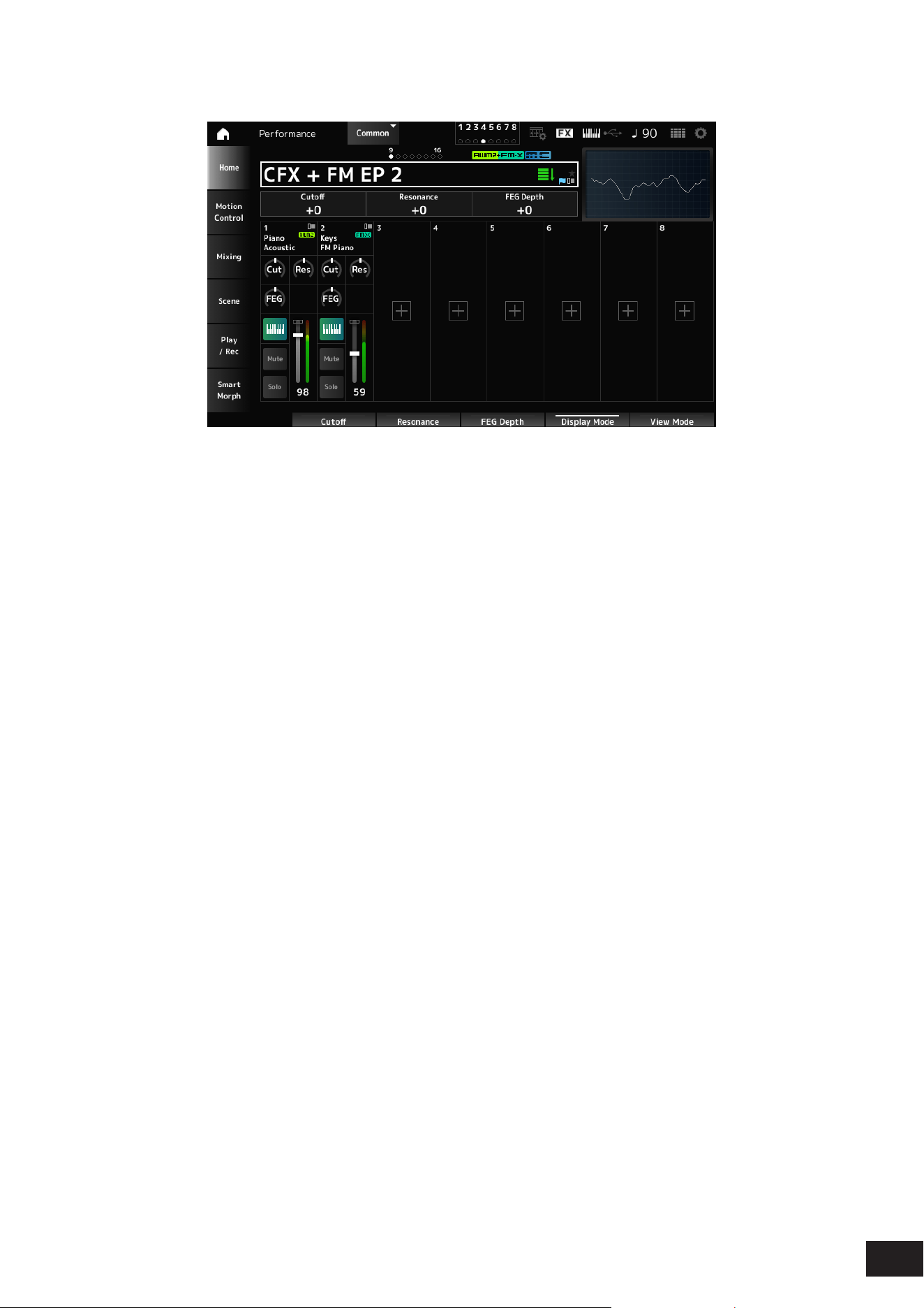
79
MODX M Operation Manual
Filter
Cutoff (Cutoff Frequency)
Changes the sound by setting the cutoff frequency of the lter.
When the Low Pass Filter is selected, larger values here result in a brighter sound, and smaller values result in a darker
sound.
This is specied as an offset value to the lter cutoff frequency for the Part.
Settings: −64–+0–+63
Resonance
Adds special characteristics to the sound by adjusting the signal level near the cutoff frequency.
This is specied as an offset value to the lter resonance for the Part.
Settings: −64–+0–+63
FEG Depth
Sets the depth range for the cutoff frequency change controlled by the FEG.
This is specied as an offset value to the Part's FEG Depth.
Settings: −64–+0–+63
Cut (Part Cutoff Frequency)
Changes the sound by setting the cutoff frequency of the Part's lter.
When the Low Pass Filter is selected, larger values here result in a brighter sound, and smaller values result in a darker
sound.
This is specied as an offset value to the lter cutoff frequency set on the Filter Type screen.
Settings: −64–+0–+63
Res (Part Resonance)
Adds special characteristics to the sound by adjusting the signal level near the Part's cutoff frequency.
This is specied as an offset value to the lter resonance set on the Filter Type screen.
Settings: −64–+0–+63
FEG (Part FEG Depth)
Adjusts the range of the cutoff frequency change controlled by the FEG setting in the Filter Type screen.
When it is set to 0, the settings in the Filter Type screen will be used as is.
Settings: −64–+0–+63
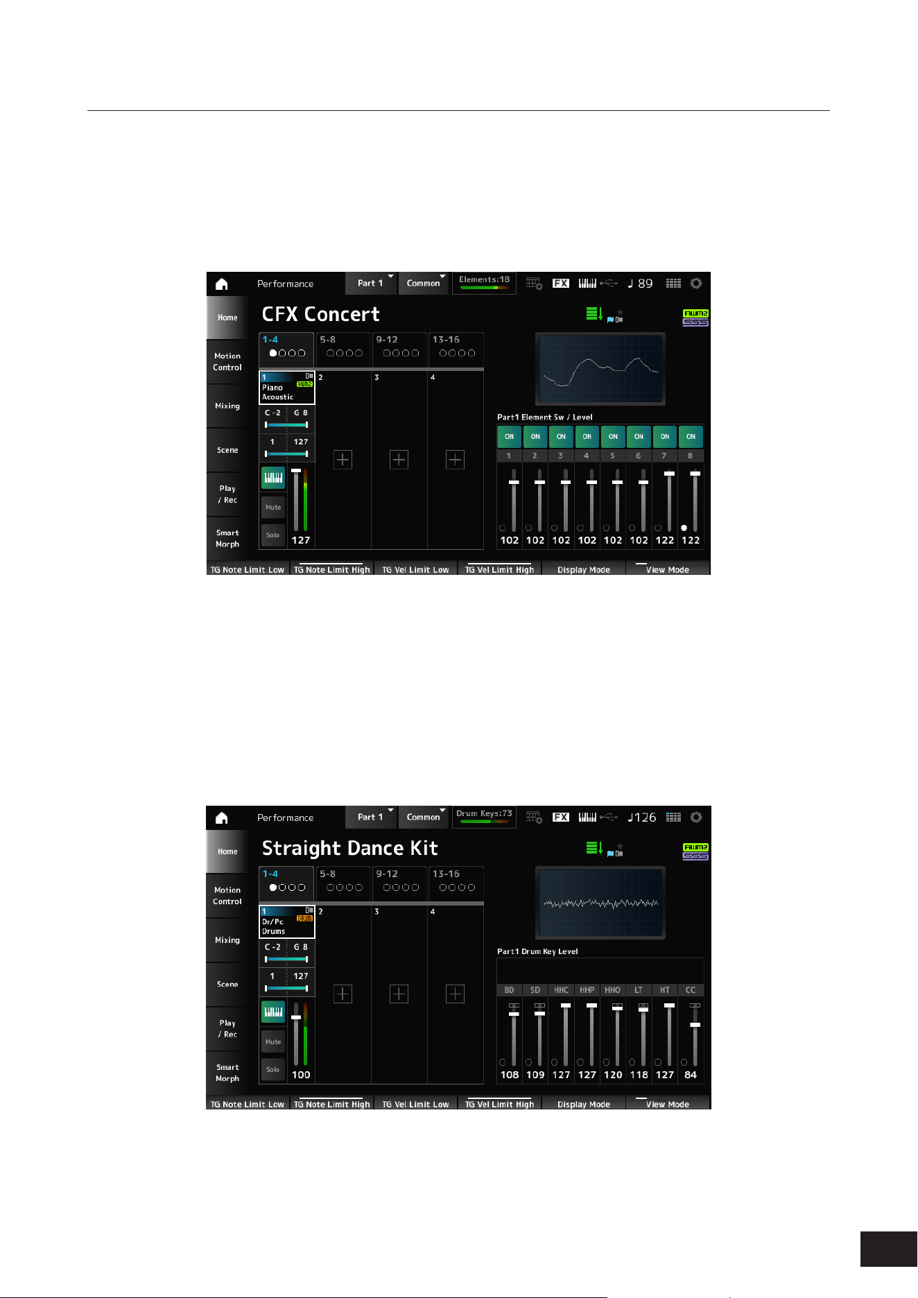
80
MODX M Operation Manual
Changing the View Mode
You can access more detailed information from the Home screen by using View Mode.
You can select a different View Mode by moving the corresponding display knob.
When the cursor is on the Performance Name, pressing the [PERFORMANCE (HOME)] button also changes the view.
Part Info
• Element Sw/Level
Displayed when the currently selected Part is a Normal Part (AWM2).
Element Sw (Element Switch)
Switches the Element On or Off.
Settings: Off, On
Element Level
Sets the output level for the Element.
Settings: 0–127
• Drum Key
Displayed when the currently selected Part is a Drum Part.
Drum Key Level
Sets the output level for the Drum Key.
Settings: 0–127
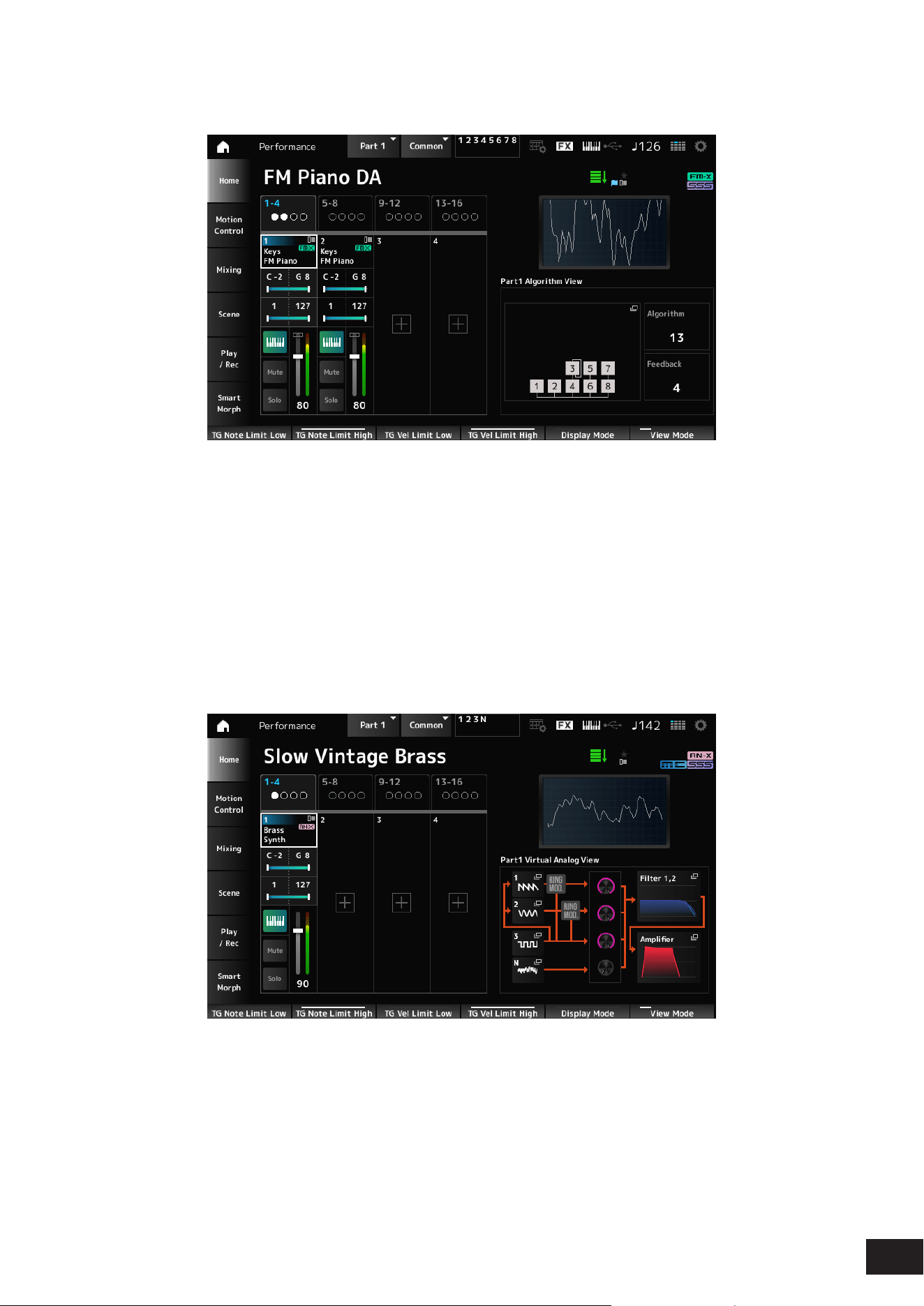
81
MODX M Operation Manual
• Algorithm
Displayed when the currently selected Part is a Normal Part (FM-X).
Algorithm (Algorithm Number)
Changes the Algorithm.
Tapping the Algorithm image calls up the Algorithm Search screen.
Settings: Refer to the Data List
Feedback (Feedback Level)
Set the degree (level) of feedback (modulating the modulator itself using the output waveform of the carrier modulated by
the modulator).
Settings: 0–7
• Virtual Analog
Displayed when the currently selected Part is a Normal Part (AN-X).
1–3 (Oscillator 1–3)
Opens the OSC/Tune screen for Part Edit (AN-X).
N (Noise)
Opens the Noise screen for Part Edit (AN-X).
Oscillator Level
Sets the output level for the Oscillator.
Settings: 0–511
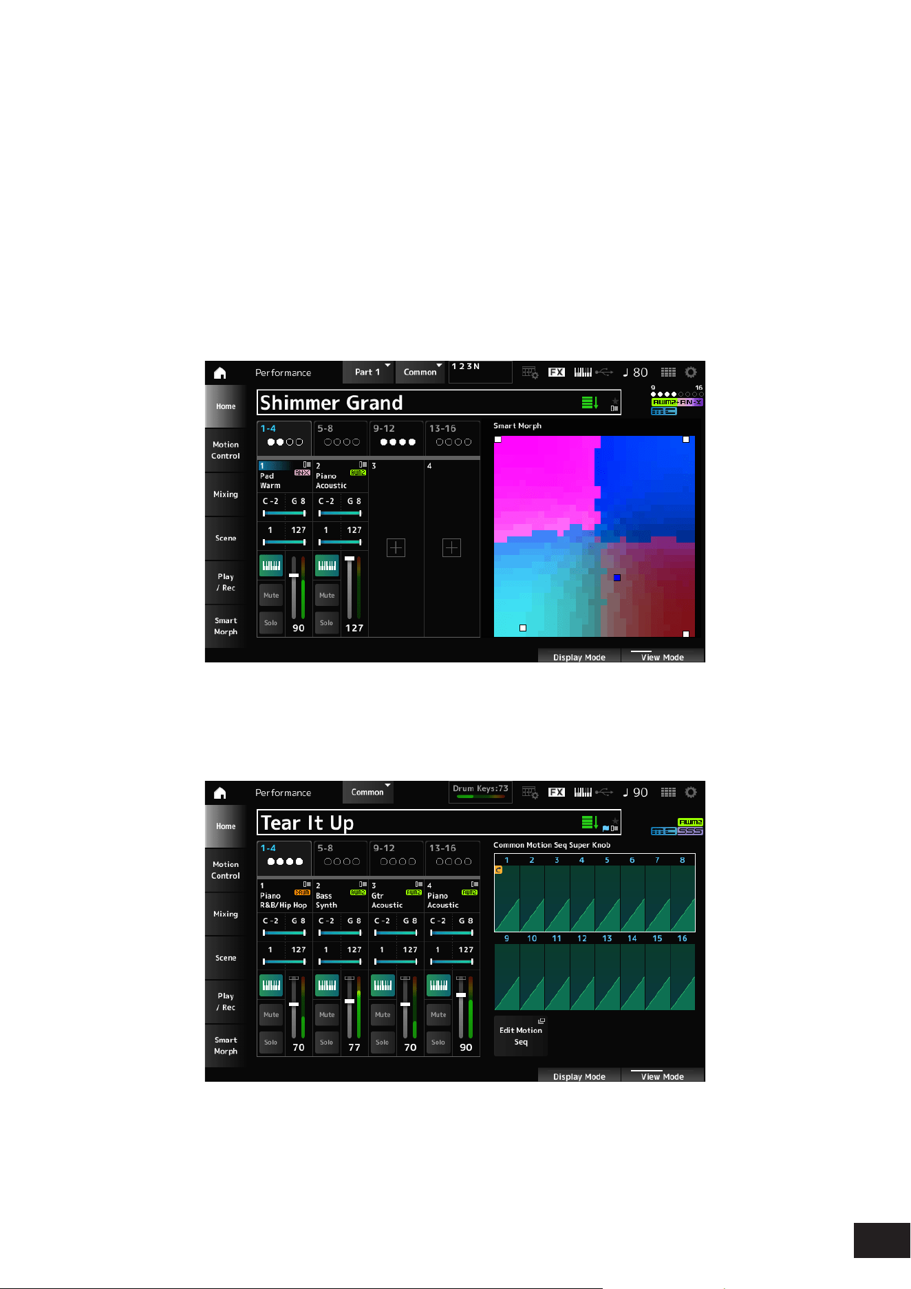
82
MODX M Operation Manual
Noise Level
Sets the noise level.
Settings: 0–511
Filter 1, 2
Opens the Filter Type screen for Part Edit (AN-X).
Amplifier
Opens the Amp EG screen for Part Edit (AN-X).
Smart Morph
The Smart Morph map is displayed.
However, the map will not be shown when there is no Smart Morph information.
Motion Seq
Shows the lane set in the View Lane of the currently selected Part.
However, it will not be displayed if the set lane is Off.
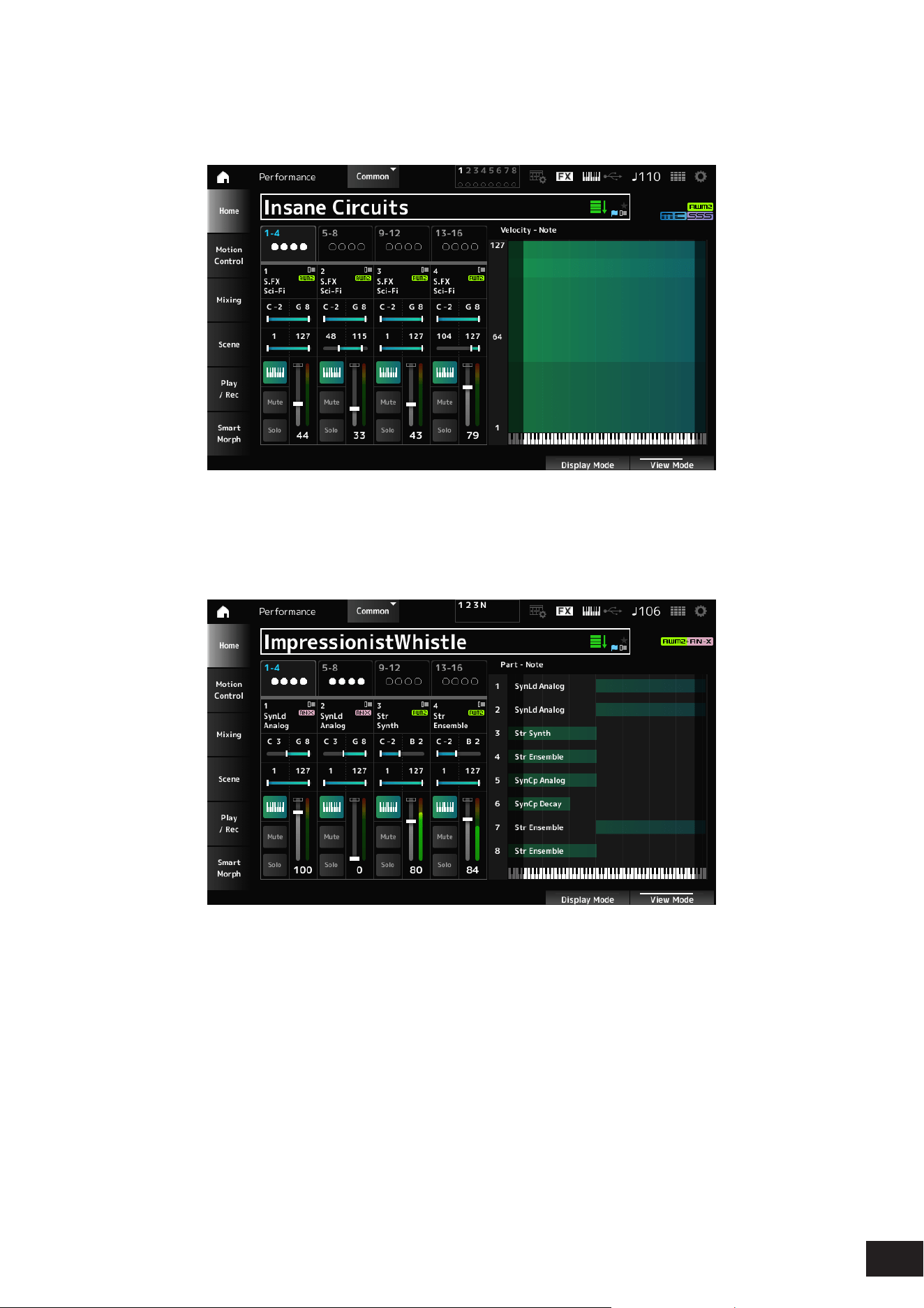
83
MODX M Operation Manual
Velocity - Note
The Velocity - Note view is displayed.
This is convenient for setting velocity splits when using multiple Parts.
Part - Note
The Part - Note view is displayed.
Shown when the View Mode is set to Part Info and the selected Part is Common.
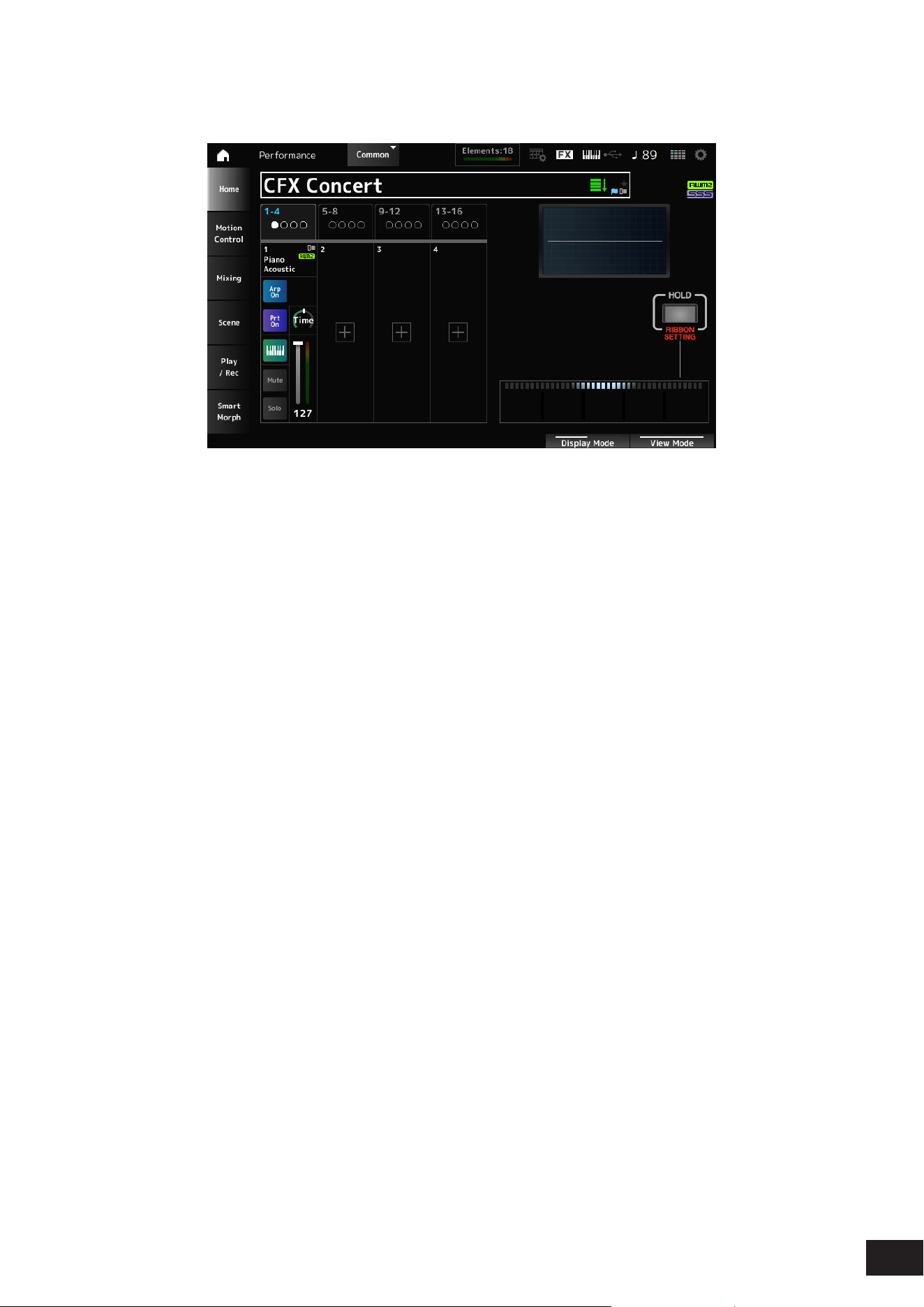
84
MODX M Operation Manual
Ribbon
Shown when the View Mode is Ribbon.
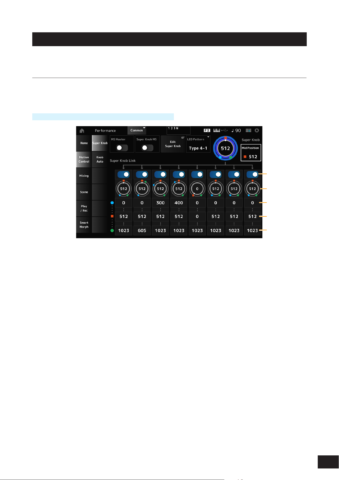
85
MODX M Operation Manual
Motion Control
On the Motion Control screen, you can set the Motion Control settings applied to the entire Performance.
Super Knob
On the Super Knob screen, you can set the values for controlling the Super Knob.
You can set a link between the Super knob and each of the assignable knobs.
Operation
[PERFORMANCE (HOME)]
→
Motion Control
→
Super Knob
(1)
(2)
(3)
(4)
(5)
(1) Super Knob Link
(2) Assignable Knob 1–8 Value
(3) Assignable Knob 1–8 Value Left
(4) Assignable Knob 1–8 Value Mid
(5) Assignable Knob 1–8 Value Right
MS Master (Motion Sequencer Master Switch)
Sets the Motion Sequencer for the entire Performance on or off.
This switch is linked to the [MSEQ] buttons on the top panel.
Settings: Off, On
Super Knob MS (Super Knob Motion Sequencer Switch)
Sets the Motion Sequencer used for the Super Knob on or off.
Settings: Off, On
Edit Super Knob
The Common Edit Control Assign screen will open. You can set the parameters to be controlled by the Super Knob.

86
MODX M Operation Manual
LED Pattern
Sets the lighting pattern of the Super knob.
Settings: Off, Type 1, Type 2-1, Type 2-2, Type 3-1, Type 3-2, Type 4-1, Type 4-2, Type 5-1, Type 5-2, Type 6, Type 7-1, Type 7-2, Type
8-1, Type 8-2, Type 9, Type 10, Type 11, Type 1B, Type 2-1B, Type 2-2B, Type 3-1B, Type 3-2B, Type 4-1B, Type 4-2B, Type
5-1B, Type 5-2B, Type 6B, Type 7-1B, Type 7-2B, Type 8-1B, Type 8-2B, Type 9B, Type 10B, Type 11B, Rotary 1, Rotary 2,
Rotary 3, Rotary 4, Rotary 5, Rotary 6, Rotary 7, Rotary 8, Rotary 9, Rotary 10
Super Knob (Super Knob Value)
Sets the Super Knob value.
Settings: 0–1023
Mid Position (Super Knob Mid Position)
Set the Mid value for the Super Knob.
Settings: Off, 1–1022
Super Knob Link
Sets the corresponding knob to link to the Super Knob.
When these switches are set to Off, the operation of the Super Knob will not affect the parameter of the knob.
Settings: Off, On
Assignable Knob 1 – 8 Value
Shows the current values for the Assignable knobs (Knobs 1–8).
Settings: 0–1023
Assignable Knob 1 – 8 Value Left
Shows the value of the assignable knobs (Knobs 1–8) when the Super Knob Value is set to 0 (or the Super Knob is turned
all the way to the left).
Settings: 0–1023
Assignable Knob 1 – 8 Value Mid
Shows the value of the assignable knobs (Knobs 1–8) when the Super Knob Value is set to Mid Position.
This parameter is not available when the Mid Position is Off.
Settings: 0–1023
Assignable Knob 1 – 8 Value Right
Shows the value of the assignable knobs (Knobs 1–8) when the Super Knob Value is set to 1023 (or the Super Knob is
turned all the way to the right).
Settings: 0–1023
NOTE
• When you set Value Left to a smaller value and Value Right to a larger value, Knobs 1–8 will move in the same direction as the Super
Knob.
• When you set Value Right to a smaller value and Value Left to a larger value, Knobs 1–8 will move in the opposite direction to the
Super Knob.
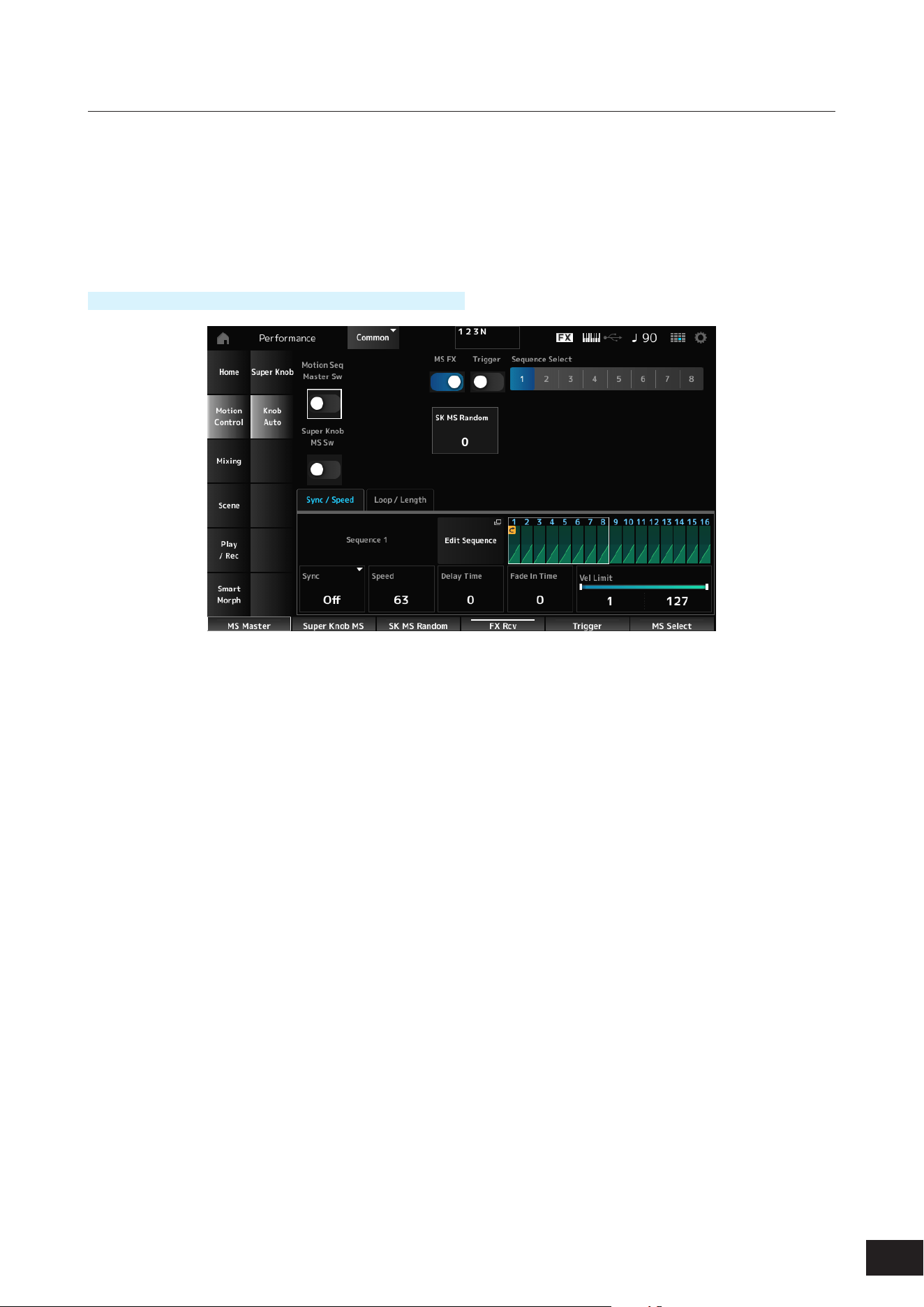
87
MODX M Operation Manual
Knob Auto
In the Knob Auto screen, you can set the Motion Sequencer for the Super Knob (Super Knob Motion Sequencer). You can
set the Motion Sequencer to automatically control the Super Knob value.
Only one Lane can be used by the Super Knob.
NOTE
Up to eight Lanes can be used at the same time for the entire Performance. However, the Lane used for the Knob Auto screen is not
included in the eight referred to here.
Operation
[PERFORMANCE (HOME)]
→
Motion Control
→
Knob Auto
Motion Seq Master Sw (Motion Sequencer Master Switch)
Sets the Motion Sequencer for the entire Performance on or off.
This switch is linked to the [MSEQ] buttons on the top panel.
Settings: Off, On
Super Knob MS Sw (Super Knob Motion Sequencer Switch)
Sets the Super Knob Motion Sequencer on or off.
Settings: Off, On
MS FX (Super Knob Motion Sequencer FX Receive)
Sets Knobs to be affected by the operation of the Super Knob.
Settings: Off, On
Trigger (Super Knob Motion Sequencer Trigger Receive)
Sets to receive the signals from the [MSEQ TRIGGER] button.
When set to On, the Motion Sequence will not be played back unless you press the [MSEQ TRIGGER] button.
Settings: Off, On
Sequence Select (Motion Sequence Select)
Changes the Motion Sequence type selection.
Settings: 1–8
SK MS Random (Super Knob Motion Sequencer Randomness)
Sets randomness of the changes in the Step value of the sequence.
Settings: 0–127
Edit Sequence
The Super Knob Motion Sequence Edit screen will open.

88
MODX M Operation Manual
Sync/Speed Tabs
Sync (Super Knob Motion Sequencer Sync)
Selects the speed and the timing for the playback of the Super Knob Motion Sequence.
Settings: Off, Tempo, Beat
Off: Plays back the Super Knob Motion Sequencer alone
Tempo: Plays back at the Performance tempo.
Beat: Plays back in sync with the beat.
• When Sync is set to Off
Speed (Super Knob Motion Sequencer Speed)
Sets the playback speed for the Motion Sequence.
Settings: 0–127
Delay Time (Super Knob Motion Sequencer Lane Key On Delay Time Length)
Sets the delay time for starting the playback of the Motion Sequence.
Settings: 0–127
Fade In Time (Super Knob Motion Sequencer Lane Fade In Time Length)
Sets the time for the Motion Sequence to reach maximum amplitude.
Settings: 0–127
• When Sync is set to something other than Off
Unit (Super Knob Motion Sequencer Unit Multiply)
Sets the percentage for stretching or compressing the Super Knob Motion Sequencer playback time.
Settings: 50%–6400%, Common
200%: The playback time is doubled, and the tempo is halved
100%: The playback time is kept unchanged
50%: The playback time is halved, and the tempo is doubled
Common: The value set in the Unit common to all Parts is applied
Delay Steps (Super Knob Motion Sequencer Lane Key On Delay Step Length)
Sets the delay time for starting the playback of the Motion Sequence.
Settings: 0–32
Fade In Steps (Super Knob Motion Sequencer Lane Fade In Step Length)
Sets the time to reach the maximum amplitude for the Motion Sequence.
Settings: 0–32
Vel Limit (Super Knob Motion Sequencer Velocity Limit)
Sets the velocity range (lowest and highest values) for playing back the Motion Sequence.
Settings: 1–127

89
MODX M Operation Manual
Loop/Length Tabs
Key On Reset (Super Knob Motion Sequencer Key On Reset)
Resets the Motion Sequence playback when you press any key on the keyboard.
This parameter is not available when the Trigger is On.
Settings: Off, Each-On, 1st-On
Each-On: Each time you play any note, playback starts from the beginning
1st-On: Playback starts from the beginning at the rst note you play. When the second note is played while the rst note is held,
playback will not be reset.
Loop (Super Knob Motion Sequencer Loop)
Sets the Motion Sequence to loop playback (in repeats) or one-shot playback.
Settings: Off, On
Loop Start (Super Knob Motion Sequencer Loop Start)
Species the starting point for the loop playback of the Motion Sequence.
Settings: 1–16 (should be below the Length setting)
Length (Super Knob Motion Sequence Length)
Sets the Motion Sequence length.
Settings: 1–16 (should be above the Loop Start setting)
MS Grid (Super Knob Motion Sequence Grid)
Sets the length of a step in the Motion Sequence.
Settings: 60, 80, 120, 160, 240, 320, 480
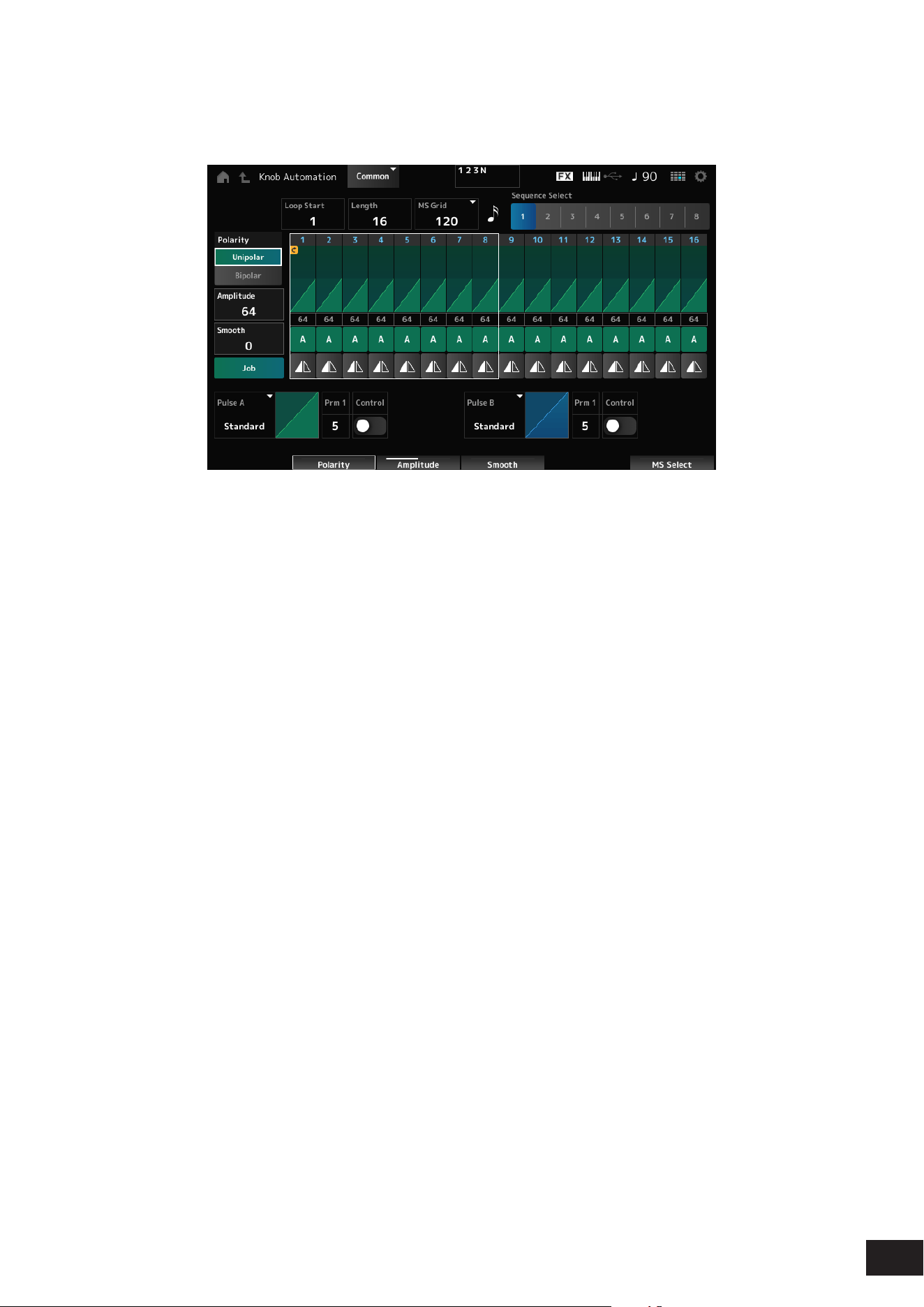
90
MODX M Operation Manual
Super Knob Motion Sequence Edit
The setting screen for the Super Knob Motion Sequencer.
You can create a sequence of up to 16 steps.
Loop Start (Super Knob Motion Sequencer Loop Start)
Species the starting point for the loop playback of the Motion Sequence.
Settings: 1–16 (should be below the Length setting)
Length (Super Knob Motion Sequence Length)
Sets the Motion Sequence length.
Settings: 1–16 (should be above the Loop Start setting)
MS Grid (Super Knob Motion Sequence Grid)
Sets the length of a step in the Motion Sequence.
Settings: 60, 80, 120, 160, 240, 320, 480
Sequence Select (Motion Sequence Select)
Changes the Motion Sequence type selection.
Settings: 1–8
Polarity (Super Knob Motion Sequence Polarity)
Sets the polarity of the Motion Sequence.
Settings: Unipolar, Bipolar
Unipolar: Only positive values are used for the parameter change
Bipolar: Both positive and negative values are used for the parameter change
Amplitude (Super Knob Motion Sequence Amplitude)
Sets the degree of changes in the Motion Sequence.
Settings: 0–127
Smooth (Super Knob Motion Sequence Smoothness)
Sets the smoothness of the changes in the Motion Sequence over time.
Settings: 0–127

91
MODX M Operation Manual
Job
Calls up the Job menu.
• Store Sequence
Saves (stores) the edited Motion Sequence.
• Load Sequence
Loads the Motion Sequence.
• Copy Sequence
Copies the Motion Sequence.
Super Knob Motion Sequence Step Value
Sets the value for each step in the Motion Sequence.
You can use Control sliders 1 to 8 to change the values for Steps 1 to 8 and Steps 9 to 16, depending on the cursor
position.
Settings: 0–127
Super Knob Motion Sequence Step Type
Sets the type and direction of each step in the Motion Sequence.
Settings: A, B, Reverse A, Reverse B
Pulse A (Super Knob Motion Sequence Step Curve Type A)
Pulse B (Super Knob Motion Sequence Step Curve Type B)
Selects a parameter change curve for Pulse A and Pulse B.
Use the Super Knob Motion Sequence Step Type to select which of the curve types to use for each step.
The vertical axis represents the time while the horizontal axis represents the step value.
Settings: (When a preset bank is selected) Standard, Sigmoid, Threshold, Bell, Dogleg, FM, AM, M, Discrete Saw, Smooth Saw,
Triangle, Square, Trapezoid, Tilt Sine, Bounce, Resonance, Sequence, Hold, Harmonic, Steps
(When a user bank is selected) Init Curve 1–32
(When loading a Library le) Curve within Library 1–24
Edit User Curve
Displayed when Init Curve is selected for Pulse A and Pulse B.
The User Curve Edit screen will open.
Prm 1 (Super Knob Motion Sequence Step Curve Parameter 1)
Prm 2 (Super Knob Motion Sequence Step Curve Parameter 2)
Adjusts the shape of the step curve in the Motion Sequence. Also, the range for the parameter value differs depending on
the Curve Type.
This setting is not available depending on the Curve Type.
Control (Super Knob Motion Sequence Step Curve Shape Control Switch)
Enables or disables the use of the knobs for controlling the step curve shape of the Motion Sequence.
Shown only when MS FX (Super Knob Motion Sequencer FX Receive) is set to On.
This setting is not available depending on the Curve Type.
Settings: Off, On
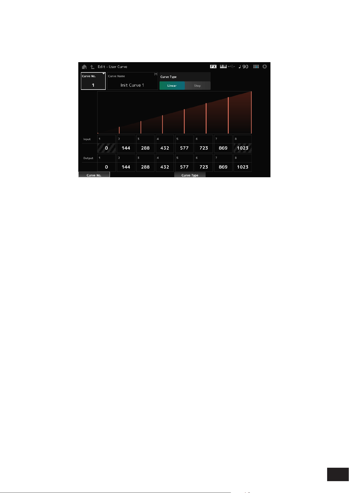
92
MODX M Operation Manual
User Curve Edit
This is the setting screen for the User Curve.
You can create an 8-point Linear curve or an 8-step curve.
Curve No. (Curve Number)
Indicates the current curve number.
Settings: 1–32
Curve Name
You can save the curve you are editing under a new name. You can use up to 20 alphanumeric characters.
Curve Type
Sets the Curve type.
Settings: Linear, Step
Input
Sets the input level for the curve.
Input 1 is xed to the value 0. Input 8 is xed to the value of 1023 when the Curve Type is set to Linear.
Settings: 0–1023
Output
Sets the output level for the curve.
Settings: 0–1023
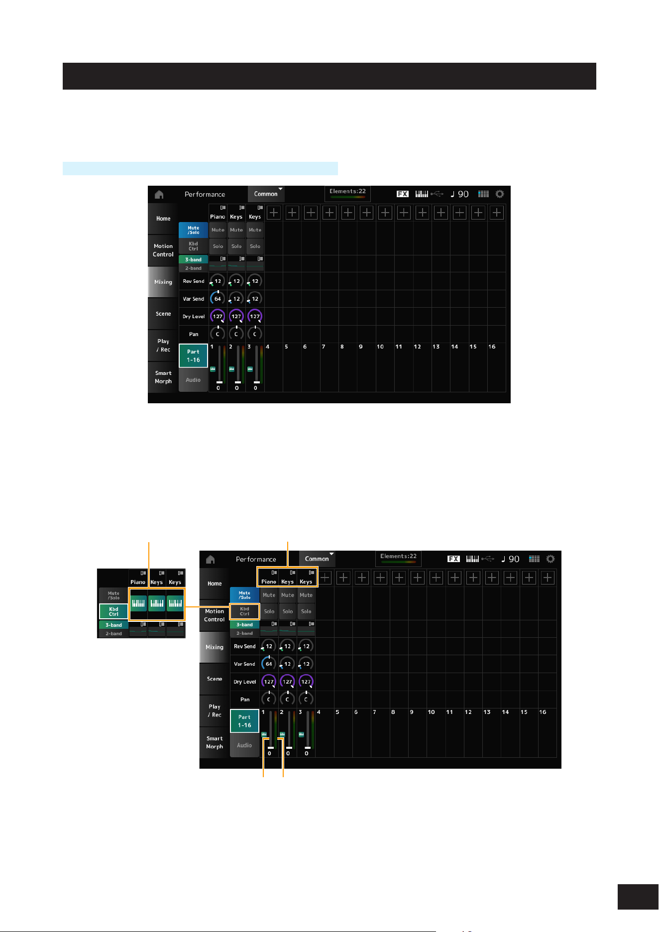
93
MODX M Operation Manual
Mixing
On the Mixing screen, you can change the mix by adjusting the volume of each Part and make effect settings.
The settings in the Mixing screen are saved (stored) in the Performance.
Operation
[PERFORMANCE (HOME)]
→
Motion Control
→
Super Knob
Part 1–16 (Part 1–16 Switch)
Audio (Audio Switch)
Changes the view.
Settings: Part 1–16, Audio (Part 1–8, Audio Part, Master)
Part 1–16 view
Sets the mix for Parts 1 to 16.
(1)(2)
(4)(3)
(1) Part Category
(2) Keyboard Control
(3) Volume
(4) Part Level Meter

94
MODX M Operation Manual
Part Category
The Main category of the selected Part is shown.
Tap to display the context menu for Category Search, Edit, Property, etc.
When a Part other than Part 1 is selected and the sound is already set for that Part, the context menu for Category
Search, Edit, Copy, and Delete is displayed. Tap [+] to add a Part.
Settings: Refer to the Data List
Mute/Solo Switch
Kbd Ctrl Switch
Switches between the Mute/Solo view and Keyboard Control view.
Mute (Part Mute)
Solo (Part Solo)
Switches Mute and Solo for the Part on or off.
Settings: Off, On
Keyboard Control
Switches Keyboard Control on or off.
For Parts 9 to 16, the buttons will not be shown since Keyboard Control cannot be set to On for those Parts.
Settings: Off, On
3-band (3-band EQ Switch)
2-band (2-band EQ Switch)
Switches between the 2-band EQ view and 3-band EQ view of Parts 1 to 16.
Settings: 3-band, 2-band
EQ (Equalizer)
Shows the EQ setting either in 3-band or 2-band views.
Tapping on the area calls up the context menu of Part EQ.
Rev Send (Reverb Send)
Sets the level of the signals sent from Parts 1 to 16 to the Reverb Effect.
Settings: 0–127
Var Send (Variation Send)
Sets the level of the signals sent from Parts 1 to 16 to the Variation Effect.
Settings: 0–127
Dry Level
Sets the dry level (or the level of the signals not processed by the System Effect) of Parts 1 to 16.
Settings: 0–127
Pan
Adjusts the Pan position (in the stereo eld) for Parts 1 to 16.
Settings: L63–C (center)–R63
Volume
Sets the volume for Parts 1 to 16.
Settings: 0–127
Part Level Meter
Shows the level for Parts 1 to 16.
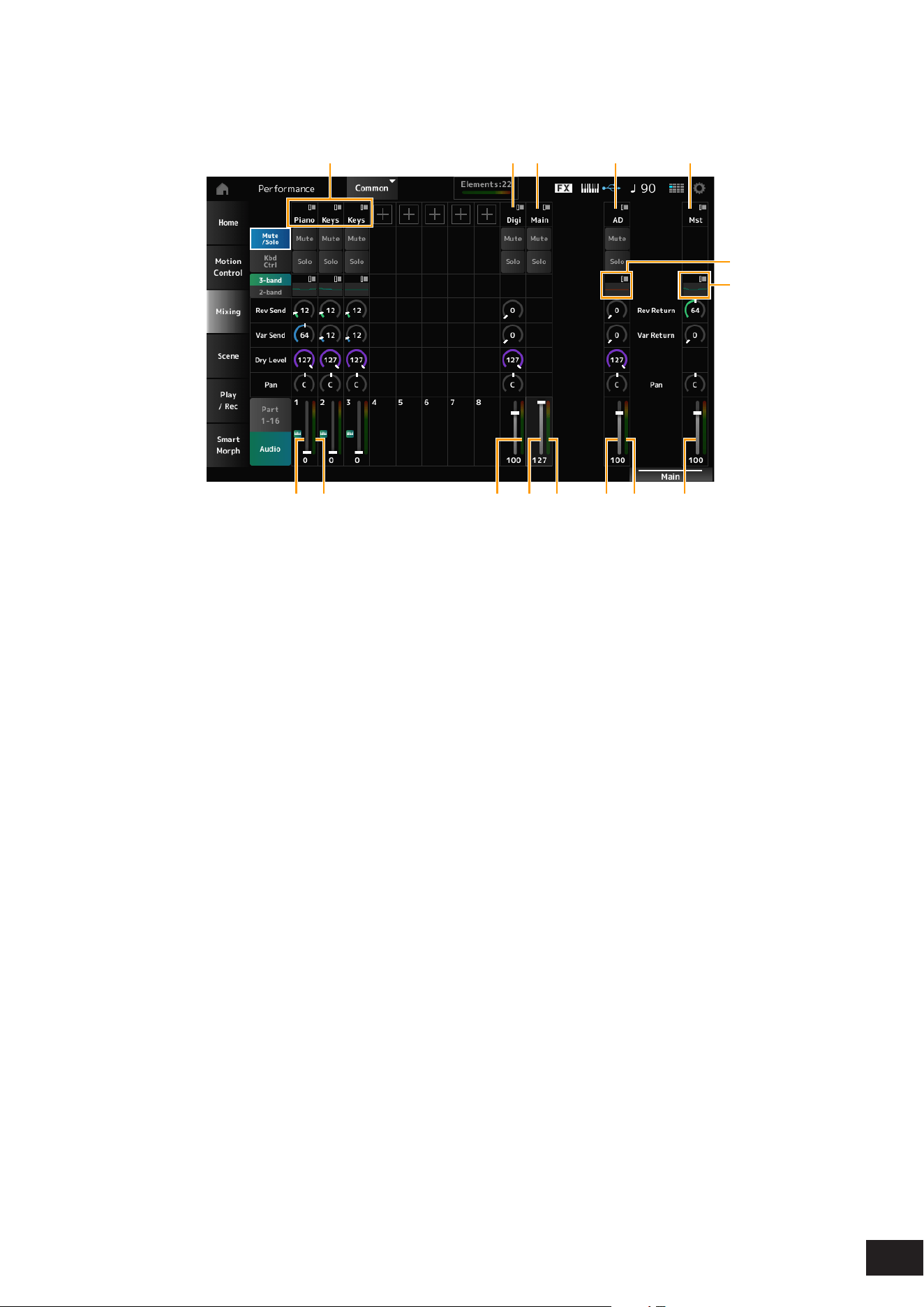
95
MODX M Operation Manual
Audio view
Sets the mix for the Audio Part.
(1)
(9)(8)
(12)(11)(10) (14)(13) (15)
(2) (3) (4) (5)
(6)
(7)
(1) Part Category
(2) Digi (Digital Part)
(3) Main (USB Main Part)
(4) AD (A/D Part)
(5) Mst (Master)
(6) A/D Part EQ
(7) Master EQ
(8) Digital Part Volume
(9) Part Level Meter
(10) Digi (Digital Part Level Meter)
(11) USB Main Monitor Volume
(12) Main (USB Main Monitor Level
Meter)
(13) A/D Part Volume
(14) AD (A/D Part Level Meter)
(15) Performance Volume
Part Category
The Main category of the selected Part is shown.
Tap to display the context menu for Category Search, Edit, Property, etc.
When a Part other than Part 1 is selected and the sound is already set for that Part, the context menu for Category
Search, Edit, Copy, and Delete is displayed. Tap [+] to add a Part.
Settings: Refer to the Data List
Digi (Digital Part)
Main (USB Main Part)
AD (A/D Part)
Mst (Master)
Tap to display the context menu for Edit, etc.
Mute/Solo Switch
Kbd Ctrl Switch
Switches between the Mute/Solo view and Keyboard Control view.

96
MODX M Operation Manual
Mute (Part Mute)
Solo (Part Solo)
Switches Mute and Solo for the Part on or off.
Settings: Off, On
A/D Part EQ
Tapping on the area calls up the context menu of Part EQ.
Digital Part Reverb Send
A/D Part Reverb Send
Sets the level of the signals sent from the A/D Part or Digital Part to the Reverb Effect.
Settings: 0–127
Digital Part Variation Send
A/D Part Variation Send
Sets the level of the signals sent from the A/D Part or Digital Part to the Variation Effect.
Settings: 0–127
Digital Part Dry Level
A/D Part Dry Level
Sets the dry level (or the level of the signals without the System Effect) of the Digital Part or A/D Part.
Settings: 0–127
Digital Part Pan
A/D Part Pan
Adjusts the Pan position (in the stereo eld) of the Digital Part or A/D Part.
Settings: L63–C (center)–R63
Digital Part Volume
A/D Part Volume
USB Main Monitor Volume
Sets the volume for the Audio Part.
Settings: 0–127
Master EQ
Shows the 5-band parametric EQ.
Tapping on the area calls up the context menu for Master EQ Edit.
Rev Return (Reverb Return)
Var Return (Variation Return)
Sets the output level (Return Level) of the signals processed by the Reverb or Variation Effect.
Settings: 0–127
Rev Send (Reverb Send)
Sets the level of the signals sent to the Reverb Effect.
Settings: 0–127
Var Send (Variation Send)
Sets the level of the signals sent to the Variation Effect.
Settings: 0–127

97
MODX M Operation Manual
Pan (Performance Pan)
Sets the Pan position (in the stereo eld) of the Performance.
This parameter value offsets the Pan setting for each Part.
Settings: L63–C (center)–R63
Performance Volume
Sets the volume for the Performance.
Settings: 0–127
Part Level Meter
Digi (Digital Part Level Meter)
Main (USB Main Monitor Level Meter)
AD (A/D Part Level Meter)
Shows the level of Parts 1 to 8 and Audio Part.
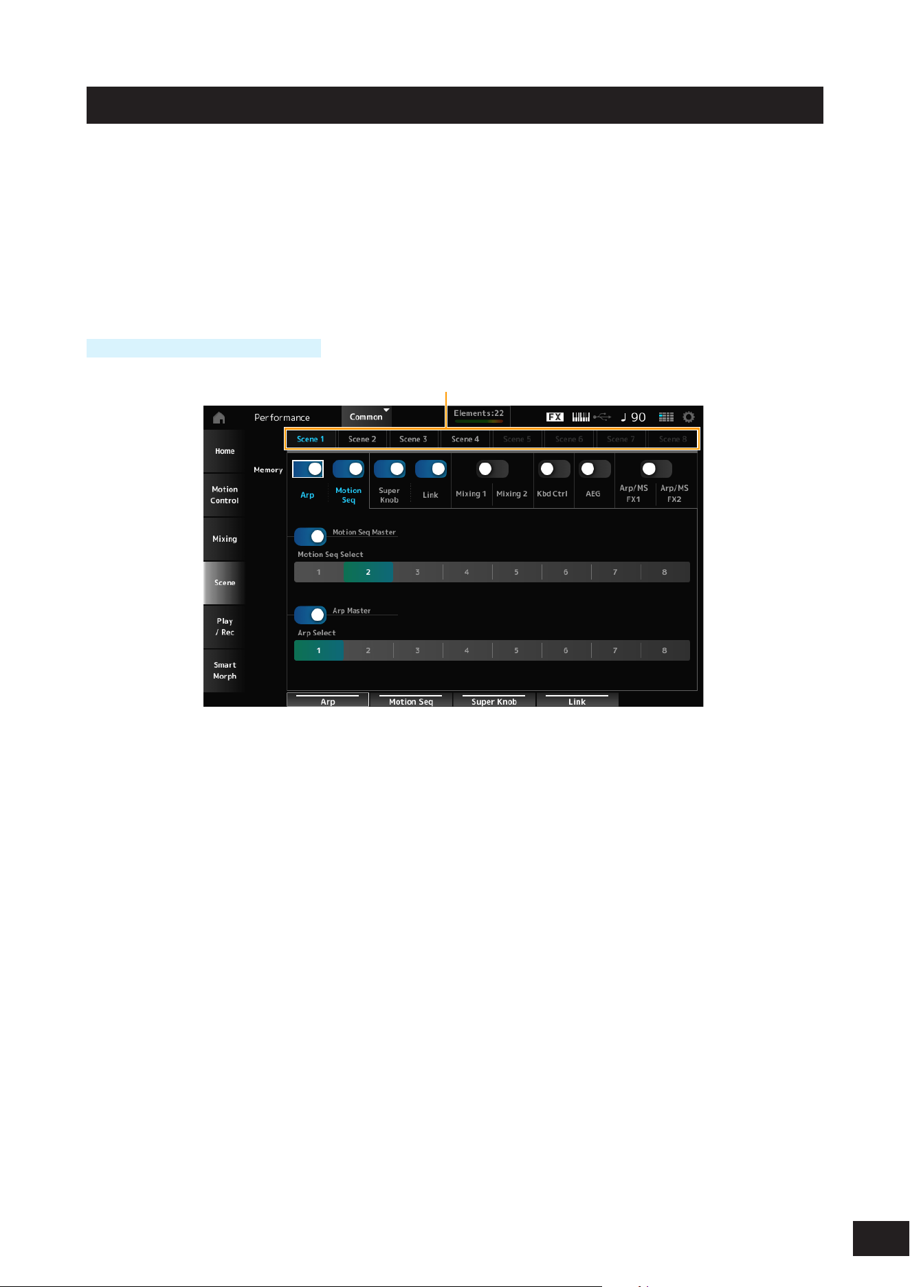
98
MODX M Operation Manual
Scene
On the Scene screen, you can register the settings for the Arpeggio type, Motion Sequence type, and Part parameters to
each of the SCENE buttons.
On this screen, set the appropriate Memory (Memory Switch) On, and edit the desired parameter values so that you can
save the settings to the Scene.
NOTE
The Scene function can be set from a screen other than Scene. You can change the assigned Scene parameters by moving the
corresponding knobs and sliders and registering the settings by simultaneously holding down the [SHIFT] button and pressing the
desired SCENE button.
Operation
[PERFORMANCE (HOME)]
→
Scene
(1)
(1) Scene Select
Scene Select
Select a Scene tab to register the settings.
The Scene1 to Scene8 tabs are linked to the SCENE buttons on the top panel.
Settings: 1–8
Memory (Memory Switch)
Selects each of the parameter values such as Arpeggio, Motion Sequencer, Super knob, Super knob link, Mixing,
Keyboard Control, Amplitude EG, and Arp/MS FX to register to the Scene.
When these switches are set to Off, the parameter values will not be shown on the display even when the corresponding
tabs are selected.
Settings: Off, On
Part 1–16 / Common
Switches the view between Part1-16 and Common.
Shown on the Mixing 1, Mixing 2, Kbd Ctrl, AEG, Arp/MS FX1, and Arp/MS FX2 tabs.
Offset (Scene Mixing / AEG Value Mode Switch)
By setting Offset to Off, some Scene parameters can be nely-adjusted.
Shown on the Mixing 1, Mixing 2, and AEG tabs.
Settings: Off (Absolute), On (Offset)
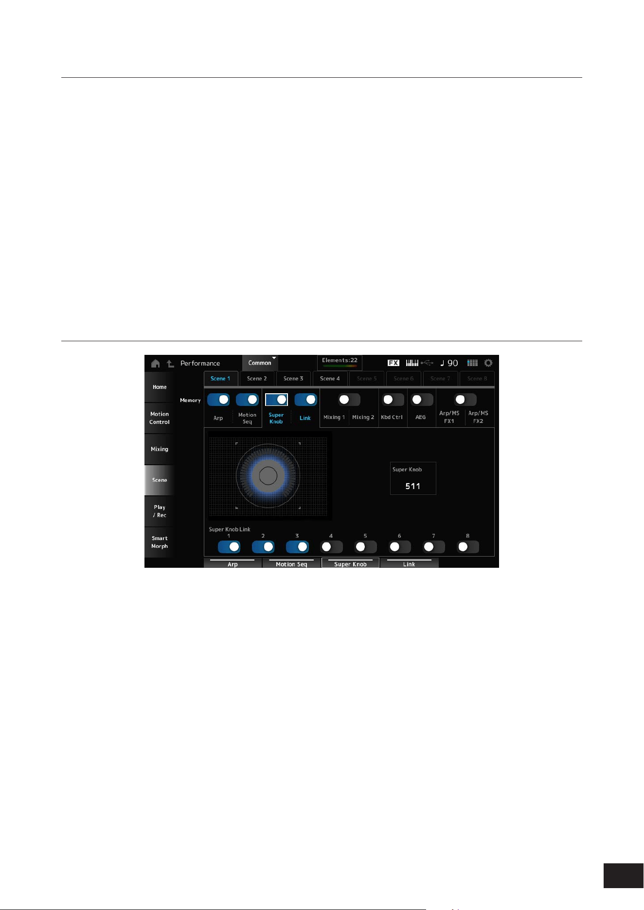
99
MODX M Operation Manual
When the Memory Switch for Arp and Motion Seq are set to On
Motion Seq Master (Motion Sequencer Master Switch)
Sets the Motion Sequencer on or off for the entire Performance.
Settings: Off, On
Motion Seq Select (Motion Sequence Select)
Changes the Motion Sequence Selection.
Settings: 1–8
Arp Master (Arpeggio Master Switch)
Sets the Arpeggio on or off for the entire Performance.
Settings: Off, On
Arp Select (Arpeggio Select)
Changes the Arpeggio selection.
Settings: 1–8
When the Memory Switch for Super Knob and Link are set to On
Super Knob (Super Knob Value)
Sets the Super Knob value.
Settings: 0–1023
Super Knob Link
Sets the link between the Super Knob and Assignable Knob 1–8 on or off.
When this switch is set to Off, operation of the Super Knob will not affect the parameters of the Assignable Knob.
Settings: Off, On
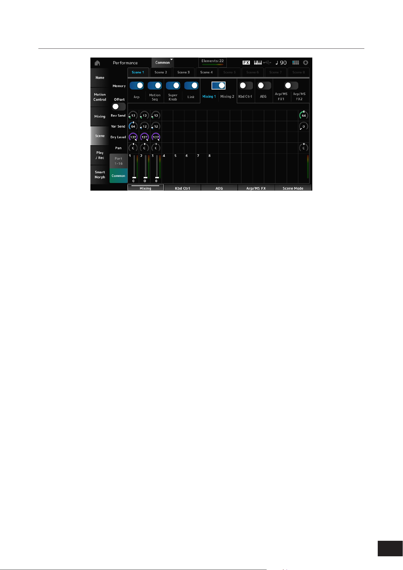
100
MODX M Operation Manual
When the Memory Switch for Mixing 1 and Mixing 2 are set to On
Mixing 1
Part 1–16 View: Scene parameters for Part 1–16 are shown.
Common View: Scene parameters for Part 1–8 and Common are shown.
Common parameters are applied to the entire Performance.
• Part 1–16 View
Rev Send (Reverb Send)
Sets the Reverb Send for each Part.
Settings: 0–127
Var Send (Variation Send)
Sets the Variation Send for each Part.
Settings: 0–127
Dry Level
Sets the Dry Level of each Part.
Settings: 0–127
Pan
Adjusts the Pan position (in the stereo eld) for each Part.
Settings: L63–C (center)–R63
Volume (Part Volume)
Sets the Volume for each Part.
Settings: 0–127
• Common View
Rev Return (Reverb Return)
Sets the Reverb Return.
Settings: 0–127
Var Return (Variation Return)
Sets the Variation Return.
Settings: 0–127
Pan (Performance Pan)
Adjusts the Pan position (in the stereo eld) of the
Performance.
Settings: L63–C (center)–R63

101
MODX M Operation Manual
Mixing 2
• Part 1-16 View
When Offset is set to On
Cutoff (Filter Cutoff Frequency)
Sets the cutoff frequency for each Part.
Settings: −64–+0–+63
Res (Filter Resonance/Width)
Sets the lter resonance or lter width for each Part.
Settings: −64–+0–+63
FEG Depth
Sets the FEG depth for each Part.
Settings: −64–+0–+63
When Offset is set to Off
By setting Offset to Off, some Scene parameters can be
nely-adjusted.
Cutoff
Settings: (AN-X, FM-X): 0–1023
Res
Settings: (AN-X): 0–255
Settings: (FM-X): 0–127
FEG Depth
Settings: (AN-X): −9600–+0–+9600
Settings: (FM-X): −64–+0–+63
NOTE
It is recommended to set Offset to On when you wish to use both
Smart Morph and Scene.
Mute (Part Mute)
Switches Mute for the Part on or off.
Settings: Off, On
Volume (Part Volume)
Sets the volume for the Part.
Settings: 0–127
• Common View
Cutoff (Cutoff Frequency)
Sets the offset value for the cutoff frequency of the Part.
Settings: −64–+0–+63
Res (Filter Resonance/Width)
Sets the offset value for the lter resonance or lter width
of the Part.
Settings: −64–+0–+63
FEG Depth
This is specied as an offset value to the Part FEG Depth.
Settings: −64–+0–+63
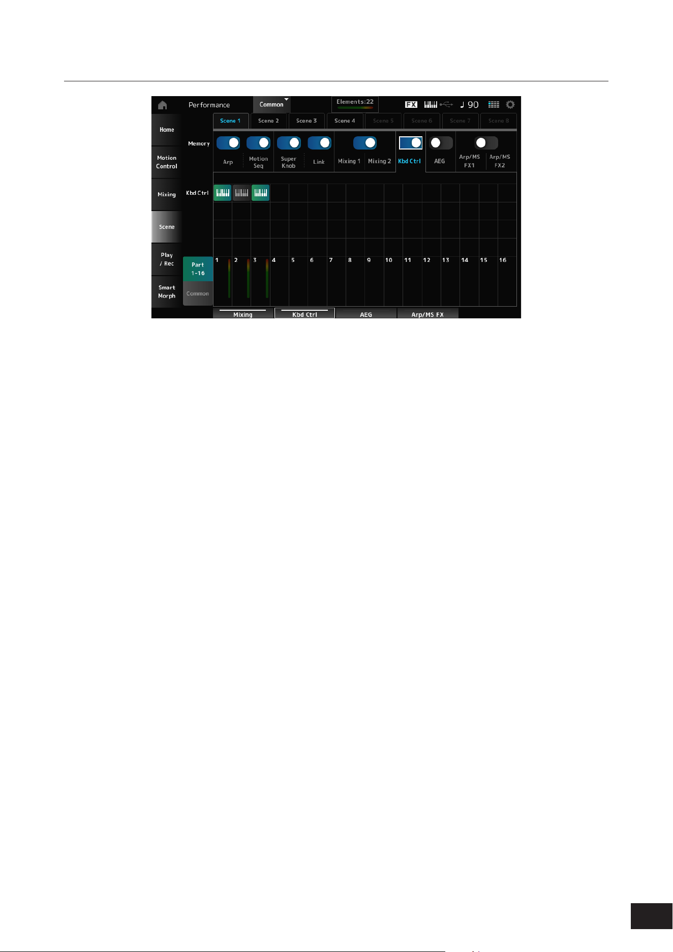
102
MODX M Operation Manual
When the Kbd Ctrl Memory Switch is set to On
Kbd Ctrl (Part Keyboard Control Switch)
Switches Keyboard Control for the Part on or off.
When Keyboard Control for the Part is set to Off, no sound will be produced when you play the keyboard.
Settings: Off (gray), On (green)

103
MODX M Operation Manual
When the AEG Memory Switch is set to On
• Part 1-16 View
When Offset is set to On
Attack (AEG Attack Time)
Sets the AEG attack time for the Part.
Settings: −64–+0–+63
Decay (AEG Decay Time)
Sets the AEG decay time for the Part.
Settings: −64–+0–+63
Sustain (AEG Sustain Level)
Sets the AEG sustain level for the Part.
Settings: −64–+0–+63
Release (AEG Release Time)
Sets the AEG release time for the Part.
Settings: −64–+0–+63
When Offset is set to Off
By setting Offset to Off, some Scene parameters can be
nely-adjusted.
Attack
Settings: (AN-X): 0–255
Decay
Settings: (AN-X): 0–255
Sustain
Settings: (AN-X): 0–511
Release
Settings: (AN-X): 0–255
• Common View
Attack
Sets the offset value to Attack (AEG Attack Time) for the
Part.
Settings: −64–+0–+63
Decay
Sets the offset value to Decay (AEG Decay Time) for the
Part.
Settings: −64–+0–+63
Sustain
Sets the offset value to Sustain (AEG Sustain Level) for
the Part.
Settings: −64–+0–+63
Release
Sets the offset value to Release (AEG Release Time) for
the Part.
Settings: −64–+0–+63
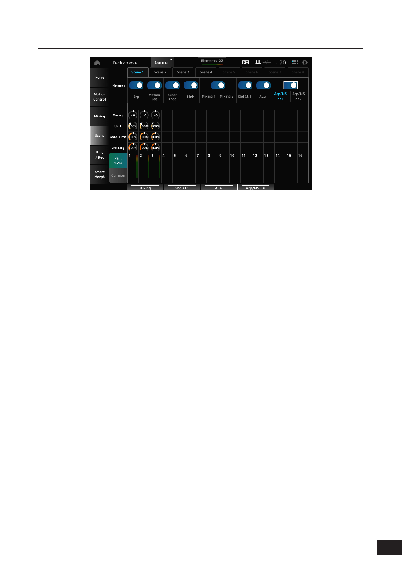
104
MODX M Operation Manual
When the Memory Switch for Arp/MS FX 1 and Arp/MS FX 2 are set to On
Arp/MS FX 1
• Part 1-16 View
Swing
Sets the swing value of the Arpeggio or Motion
Sequencer for each Part.
Settings: −120 –+0–+120
Unit (Part Unit Multiply)
Sets the percentage for stretching or compressing the
playback time of the Arpeggio or Motion Sequencer for
each Part.
Settings: 50%–400%, Common
200%: The playback time is doubled, and the tempo is
halved
100%: The playback time is kept unchanged
50%: The playback time is halved, and the tempo is
doubled
Common: The value set in the Unit (Common Unit
Multiply) common to all Parts is applied
Gate Time (Arp Gate Time Rate)
Sets the Arpeggio gate time rate for each Part.
Settings: 0%–200%
Velocity (Arp Velocity Rate)
Sets the Arpeggio velocity rate for each Part.
Settings: 0%–200%
• Common View
Swing
Sets the offset value to Swing for each Part.
Settings: −120 –+0–+120
Unit (Common Unit Multiply)
Sets the Unit Multiply for all Parts.
Settings: 50%–400%
200%: The playback time is doubled, and the tempo is
halved
100%: The playback time is kept unchanged
50%: The playback time is halved, and the tempo is
doubled
Gate Time (Arp Gate Time Rate)
Sets the offset value to Arpeggio Gate Time Rate for each
Part.
Settings: −100–+0–+100
Velocity (Arp Velocity Rate)
Sets the offset value to Arpeggio Velocity Rate for each
Part.
Settings: −100–+0–+100

105
MODX M Operation Manual
Arp/MS FX 2
• Part 1-16 View
Amp (Motion Sequencer Amplitude Part Offset)
Sets the offset value to Motion Sequencer Amplitude for
each Part.
Settings: −127–+0–+127
Shape (Motion Sequencer Pulse Shape Part Offset)
Sets the offset value to Motion Sequencer Pulse Shape
for each Part.
Settings: −100–+0–+100
Smooth (Motion Sequencer Smoothness Part Offset)
Sets the offset value to Motion Sequencer Smoothness
for each Part.
Settings: −127–+0–+127
Random (Motion Sequencer Randomness)
Sets the offset value to Motion Sequencer Randomness
for each Part.
Settings: 0–127
• Common View
Amp (Motion Sequencer Amplitude Performance
Offset)
Sets the offset value to Motion Sequencer Amplitude for
all Parts.
Settings: −127–+0–+127
Shape (Motion Sequencer Pulse Shape Performance
Offset)
Sets the offset value to Motion Sequencer Pulse Shape
for all Parts.
Settings: −100–+0–+100
Smooth (Motion Sequencer Smoothness
Performance Offset)
Sets the offset value to Motion Sequencer Smoothness
for all Parts.
Settings: −127–+0–+127
Random (Motion Sequencer Randomness
Performance Offset)
Sets the offset value to Motion Sequencer Randomness
for all Parts.
Settings: −127–+0–+127
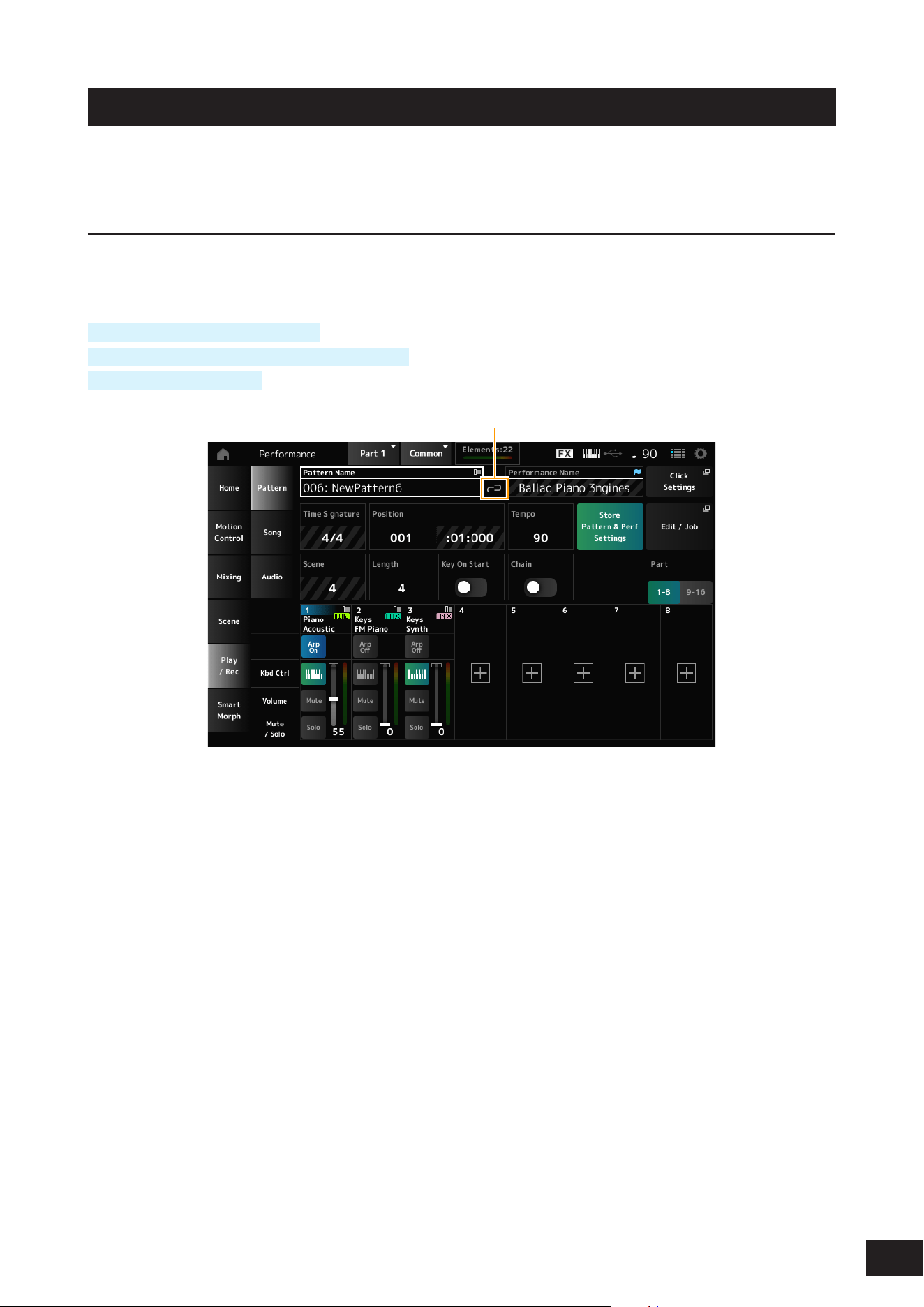
106
MODX M Operation Manual
Play/Rec
On the Play/Rec screen, you can record Patterns and Songs to the Internal memory of this instrument, and Audio to a
USB ash drive, and play back your recordings.
Pattern
Playback and playback standby
Operation
[SONG/PATTERN] button
→
Pattern
[PERFORMANCE (HOME)]
→
Play/Rec
→
Pattern
[
] (Play) button
→
Pattern
(1)
(1) Link Icon
Pattern Name
Shows the name of the selected Pattern.
Tap to display the context menu for Load, Rename, and New Pattern.
You can select a Pattern by using the [INC/YES] and [DEC/NO] buttons when the cursor is on the Pattern Name.
Link Icon
The Link Icon is shown if the Performance used for recording the Pattern and the selected Performance are the same. If
not, a broken Link Icon will be shown.
Performance Name
Shows the name of the selected Performance.
NOTE
The blue ag will be shown at the top right of the Performance Name when you change a parameter in the Performance.
Click Settings
Opens the Tempo Settings screen.

107
MODX M Operation Manual
Time Signature
Shows the meter for the Pattern.
Position
Sets the position for starting playback and recording, as well as the current playback position.
The number shown on the left is the measure, and the numbers shown on the right are the beats and ticks.
Tempo
Sets the tempo for Pattern playback.
Settings: 5–300
Store Pattern & Perf Settings (Store Pattern and Performance Settings)
Saves the link between the edited Patterns and the Performance used.
NOTE
If you have edited the Performance parameters, you will also need to store the Performance.
Edit/Job
Opens the screen for Pattern edit and jobs. By using the Pattern function, you can register a sequence for each Scene.
Scene
Shows the selected Scene number.
This switch is linked to the SCENE buttons on the top panel.
Length (Section Length)
Sets the sequence length of the selected Scene.
Settings: 1–256
Key On Start
Sets the Pattern to start recording or playback the moment you press a key on the keyboard.
Settings: Off, On
Chain
Enables chain playback.
Settings: Off, On
Undo ***
Cancels the previous action and returns to the previous state.
This button becomes available when one or more Jobs have been used after a sequence has been recorded.
Redo ***
Restores the action canceled using Undo. This button is only active after Undo *** has been used.
Part 1–8
Part 9–16
Switches between Part views
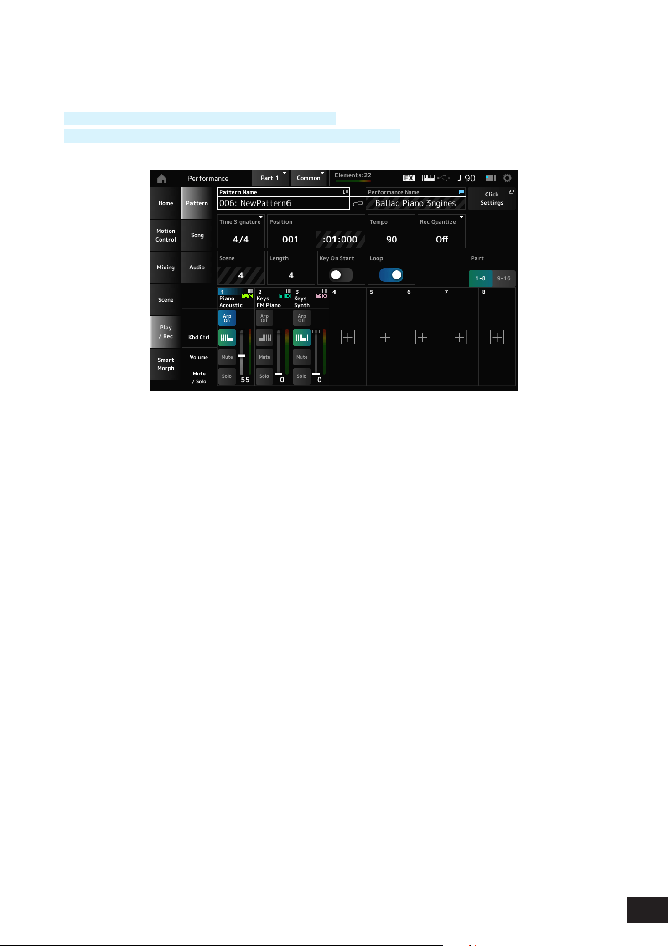
108
MODX M Operation Manual
Recording standby
Operation
[SONG/PATTERN] button
→
Pattern
→
[
] (Record) button
[PERFORMANCE (HOME)]
→
Play/Rec
→
Pattern
→
[
] (Record) button
Time Signature
Sets the meter of the Scene.
Settings: 1/16–16/16, 1/8–16/8, 1/4–8/4
Rec Quantize (Record Quantize)
Quantize is a function that corrects the recorded notes to be on the exact fraction of the beat (in note values).
Settings: Off, 60 (thirty-second note), 80 (sixteenth note triplet), 120 (sixteenth note), 160 (eighth note triplet), 240 (eighth note),
320(quarter note triplet), 480 (quarter note)
Loop
When set to On, Pattern recording continues in a loop.
Settings: Off, On
NOTE
Pressing the [
] (Record) button during Song recording sets the recorder to Rehearsal mode and makes the [
] (Record) button ash.
In Rehearsal mode, playback of the Pattern continues but recording is temporarily paused, making it useful for practicing.
You can return to Recording mode by pressing the [
] button again.
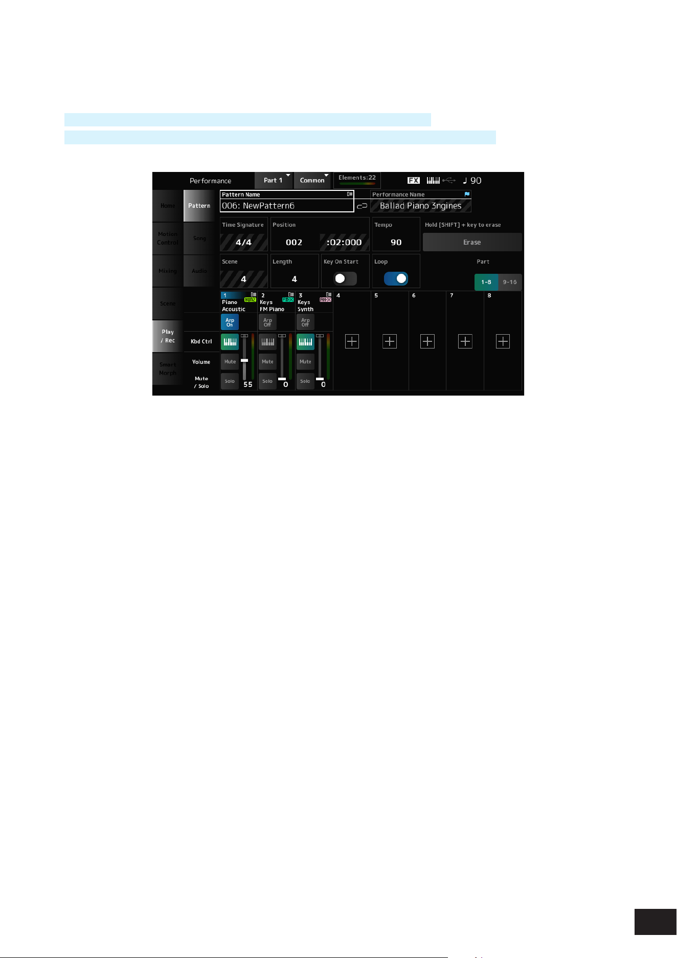
109
MODX M Operation Manual
Recording
Operation
[SONG/PATTERN] button
→
Pattern
→
[
] (Record) button
→
[
] (Play) button
[PERFORMANCE (HOME)]
→
Play/Rec
→
Pattern
→
[
] (Record) button
→
[
] (Play) button
Hold [SHIFT] + key to erase
Erase
You can delete specic note events by holding down the [SHIFT] button and pressing the key corresponding to the note
you wish to delete.
Alternately, you can tap on the Erase button on the screen to turn on the function, and then press the corresponding key
on the keyboard to delete the note event.
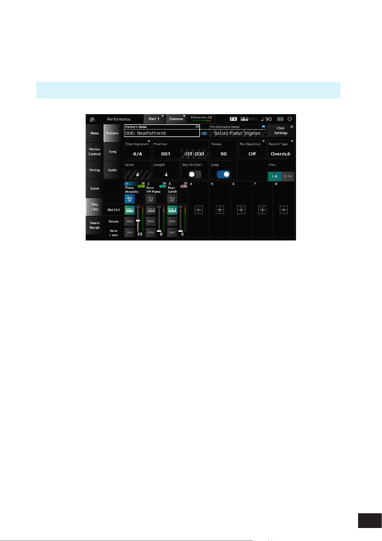
110
MODX M Operation Manual
Overdub recording
When you operate a controller during overdub recording, you can delete the existing events of that controller and record
the operation as new events.
Operation
[PERFORMANCE (HOME)]
→
Play/Rec
→
Pattern
→
(with the Song already recorded)
→
[
] (Record) button
→
Tap
Rec ord Type
→
Select Overdub from the menu
→
[
] (Play) button
Record Type
Selects from Replace or Overdub recording.
Settings: Replace, Overdub
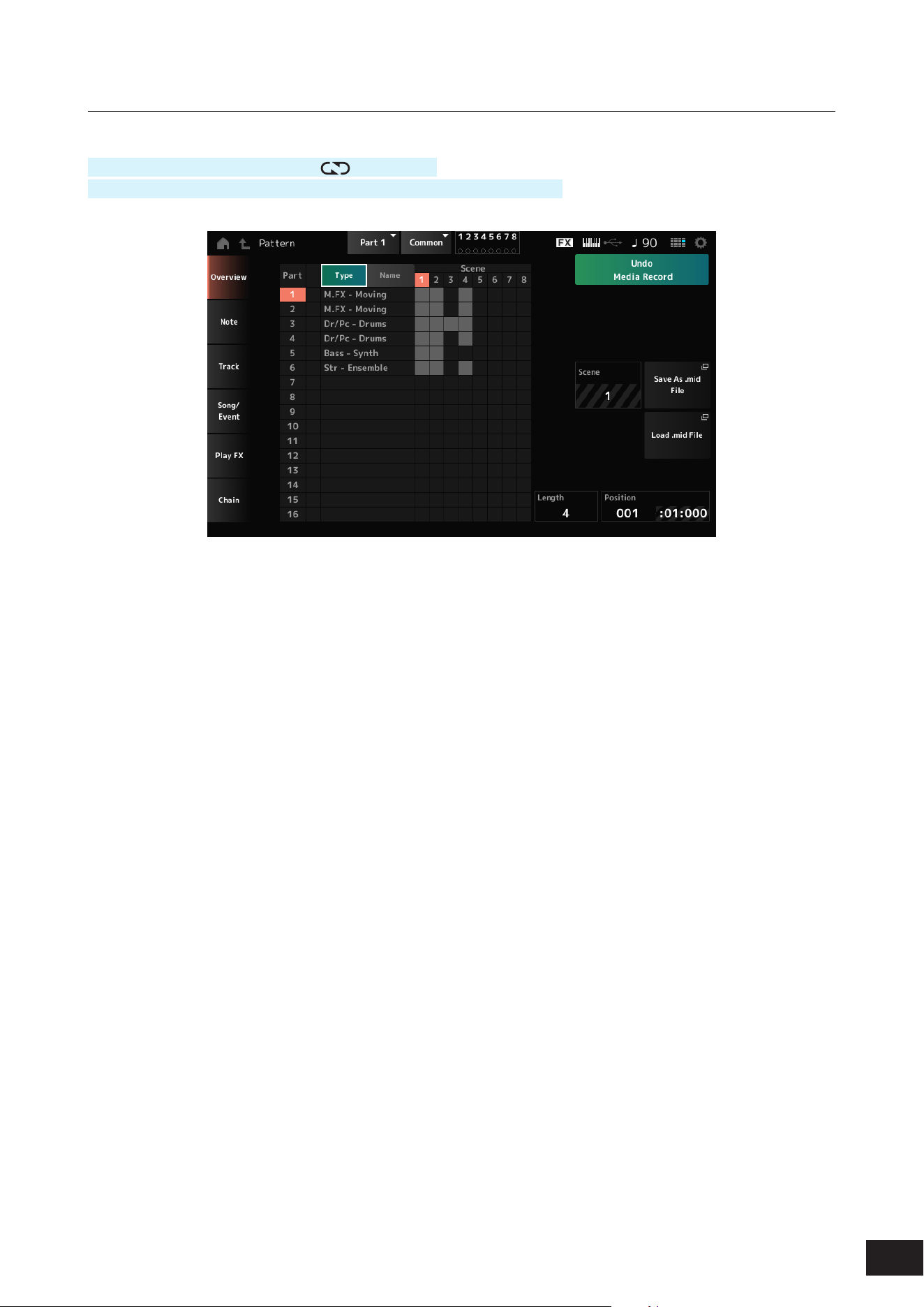
111
MODX M Operation Manual
Pattern Edit Overview
Operation
[
] (Play) button
→
Pattern
→
[EDIT/ ]
→
Overview
[PERFORMANCE (HOME)]
→
Play/Rec
→
Pattern
→
Edit/Job
→
Overview
Type
Tap this button to see the Main and Sub categories of the Part.
It also changes the list shown on the Play/Rec screen.
Name
Tap to see the Part Name.
It also changes the list shown on the Play/Rec screen.
Part Mute Icon
Part Solo Icon
Shows the status of mute and solo settings for the Part.
Undo ***
Cancels the previous action and returns to the previous state.
This button becomes available when one or more Jobs have been used after a sequence has been recorded. Common
operations for all tabs on the Pattern Edit screen.
Redo ***
Restores the recording that has been canceled by Undo. This button is only active after Undo *** has been used.
Common operations for all tabs on the Pattern Edit screen.
Scene
Shows the selected Scene number.
Save As .mid File
Opens the Save screen. You can save the sequence of the selected Scene as a MIDI le.
Load .mid File
Opens the Load screen for loading a MIDI le.
After you have selected a MIDI le, select a Pattern and Scene in the load location.
Length
Sets the sequence length of the selected Scene.
Position
Shows the current position for the Scene playback, and lets you specify the playback position.
Settings: 001–256
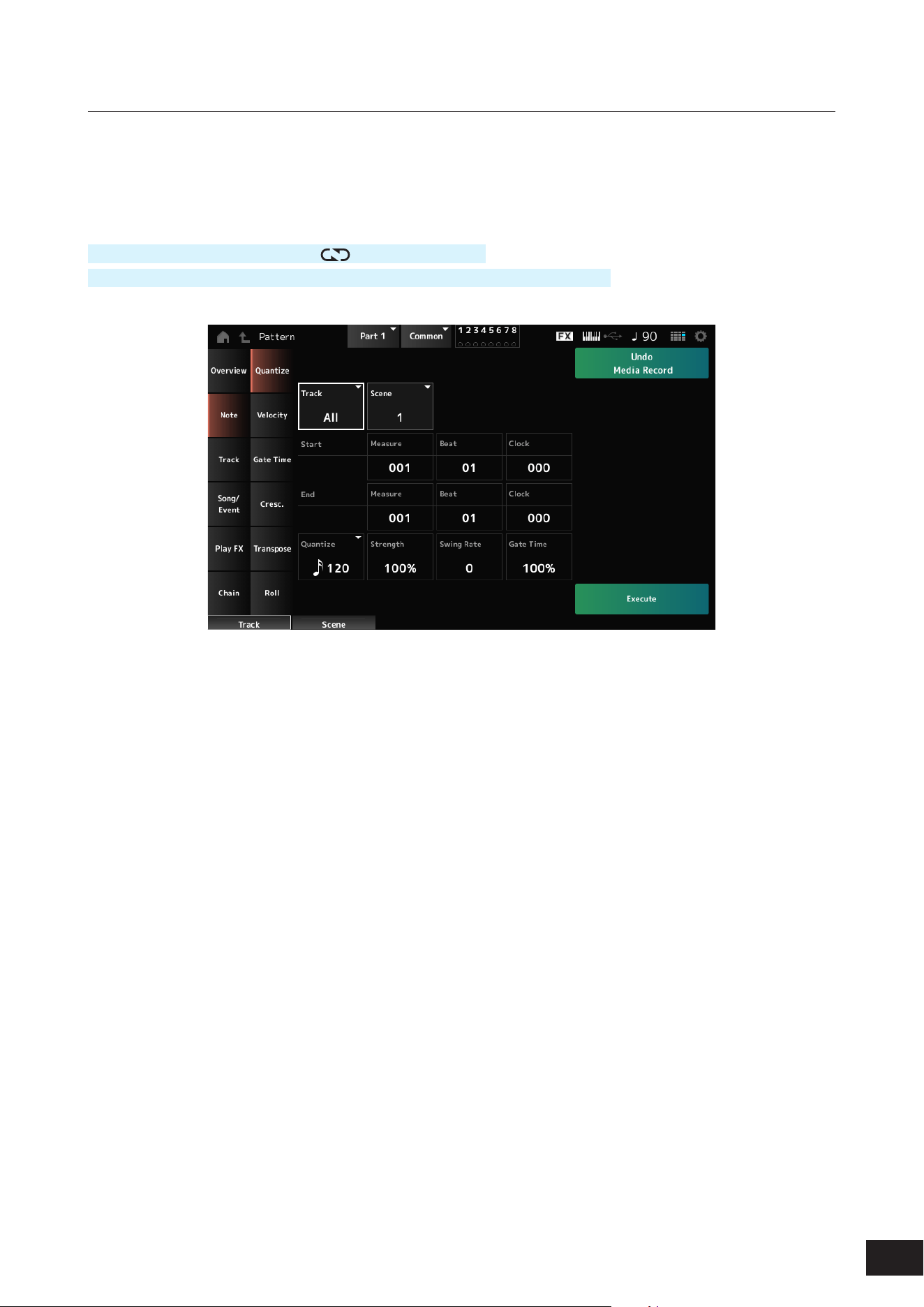
112
MODX M Operation Manual
Pattern Edit Note
Quantize
Quantization is the process of adjusting the timing of note events by moving them closer to the nearest exact beat. You
can use this feature, for example, to improve the timing of a Pattern you have recorded in real time.
Operation
[
] (Play) button
→
Pattern
→
[EDIT/ ]
→
Note
→
Quantize
[PERFORMANCE (HOME)]
→
Play/Rec
→
Pattern
→
Edit/Job
→
Note
→
Quantize
Track
Species the track for the job.
Settings: All, 1–16
Scene
Species the Scene for the job.
Settings: 1–8
Start Measure
Species the starting measure position for the job.
Settings: 001–257
Start Beat
Species the starting beat position for the job.
Settings: Depends on the Time Signature setting
Start Clock
Species the starting clock position for the job.
Settings: Depends on the Time Signature setting

113
MODX M Operation Manual
End Measure
Species the ending measure position for the job.
Settings: 001–257
End Beat
Species the ending beat position for the job.
Settings: Depends on the Time Signature setting
End Clock
Species the ending clock position for the job.
Settings: Depends on the Time Signature setting
Quantize
Sets the quantization resolution (or a note to be used as a base for the quantization).
Settings: Thirty-second note, sixteenth note triplet, sixteenth note, eighth note triplet, eighth note, quarter note triplet, quarter note,
sixteenth note + sixteenth note triplet, eighth note + eighth note triplet
Strength
Sets the “magnetic strength” of the quantization.
When this parameter is set to 100%, all notes will move to the position specied in Quantize while a setting of 0% results
in no quantization.
Settings: 0%–100%
Swing Rate
Changes the timing of the even-numbered beats (backbeats) counted from the value specied in Quantize to add a swing
feel to the rhythms.
Settings: Depends on the Quantize (quantization resolution) setting.
When Quantize is set to quarter note, eighth note, sixteenth note, or thirty-second note: 0 to half the grid
When Quantize is set to quarter note triplet, eighth note triplet, or sixteenth note triplet: 0 to half the grid
When Quantize is set to eighth note + eighth note triplet, or sixteenth note + sixteenth note triplet: 0 to half the triplet
grid
Gate Time
Changes the gate time (or the actual time for the note to be played) of the even-numbered beats (backbeats) counted from
the value specied in Quantize to add a swing feel to the rhythms.
Settings: 0%–200%
Execute
Carries out the selected Job to the MIDI sequence. Common operations for all tabs on the Pattern Edit screen.

114
MODX M Operation Manual
Velocity
Changes the sound strength (velocity) of the notes in the specied range.
NOTE
Velocity is modied using the following formula
Adjusted Velocity = (Original Velocity × Rate) + Offset
If the result is 0 or less, the value is set to 1. If the result is higher than 128, the value is set to 127.
Operation
[
] (Play) button
→
Pattern
→
[EDIT/ ]
→
Note
→
Velocity
[PERFORMANCE (HOME)]
→
Play/Rec
→
Pattern
→
Edit/Job
→
Note
→
Velocity
Set All
Sets the velocity of all notes in the selected section.
When set to Off, Set All will not work.
When set to anything other than Off, Rate and Offset will be disabled.
Settings: Off, 001–127
Rate
Sets the percentage for changing the velocity.
When set to 99% or lower, the velocity will be slower. When set to 101% or higher, the velocity will be faster. At 100% the
velocity will be kept unchanged.
This parameter cannot be changed when Set All is set to anything other than Off.
Settings: 0%–200%
Offset
Sets the value to add to or subtract from the original Velocity value.
When set to −1 or smaller, the velocity will be slower. When set to +1 or larger, the velocity will be faster. When set to 0,
the velocity will be kept unchanged.
This parameter cannot be changed when Set All is set to anything other than Off.
Settings: −127– 0 –+127
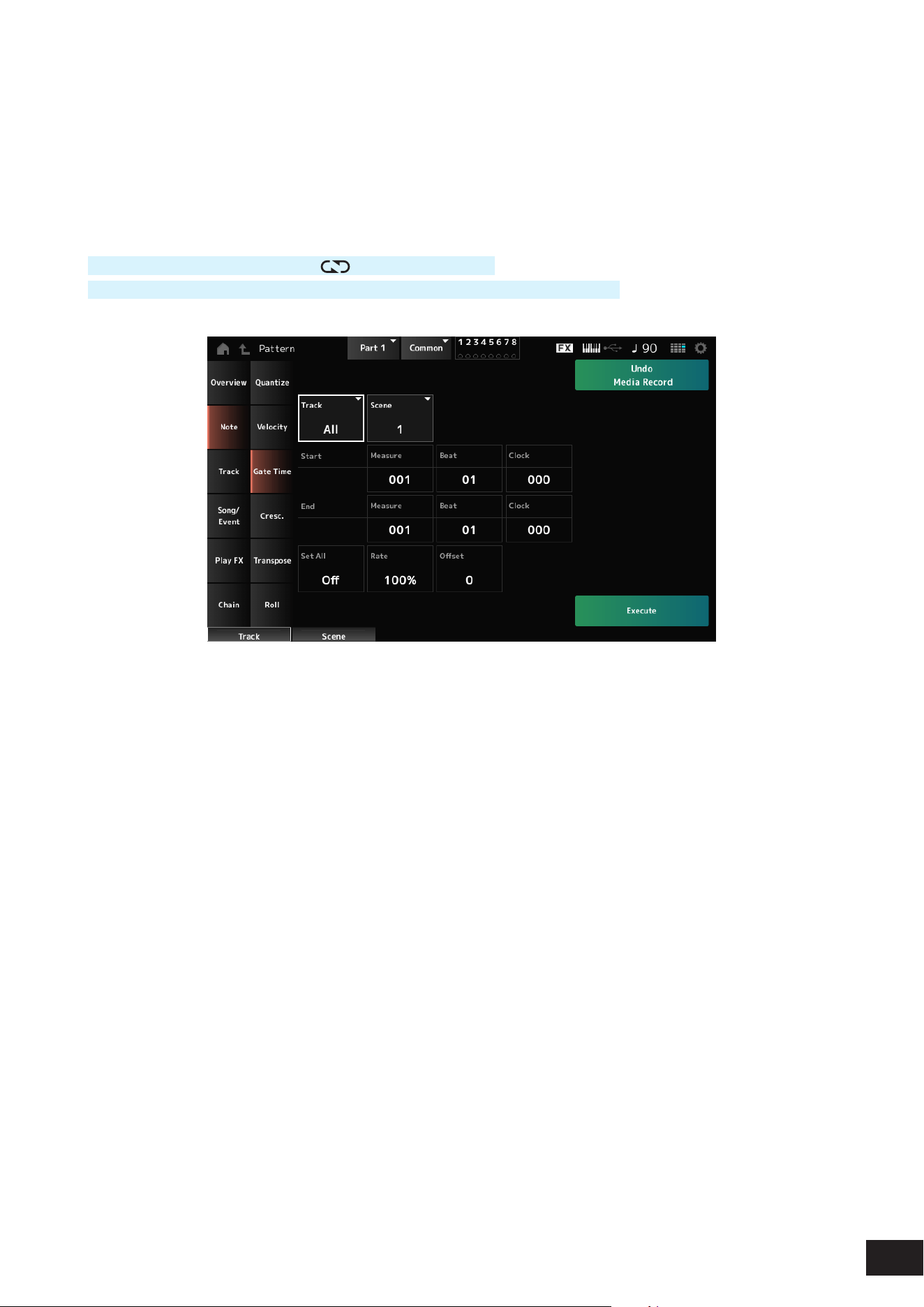
115
MODX M Operation Manual
Gate Time
Changes the sound time (gate time) of the notes in the specied range.
NOTE
Gate time is modied using the following formula
Adjusted Gate Time = (Original Gate Time × Rate) + Offset
If the result is 0 or lower, the value is set to 1.
Operation
[
] (Play) button
→
Pattern
→
[EDIT/ ]
→
Note
→
Gate Time
[PERFORMANCE (HOME)]
→
Play/Rec
→
Pattern
→
Edit/Job
→
Note
→
Gate Time
This is the same as Pattern Edit Note
→
Velocity, except that the Set All setting values are different.
Set All
Settings: Off, 001–9999

116
MODX M Operation Manual
Cresc. (Crescendo)
Applies a gradual increase (crescendo) or decrease (decrescendo) of the velocity of notes in the specied range
Operation
[
] (Play) button
→
Pattern
→
[EDIT/ ]
→
Note
→
Cresc.
[PERFORMANCE (HOME)]
→
Play/Rec
→
Pattern
→
Edit/Job
→
Note
→
Cresc.
Velocity Range
Sets the intensity of the crescendo or decrescendo.
Within the specied range, gradually increases or decreases the intermediate velocities so that the nal velocity becomes
the "Initial velocity value + Velocity Range value" based on the initial velocity. If the nal velocity is 0 or lower, the nal
velocity is set to 1, and if it is 128 or higher, it is set to 127.
A positive value produces a crescendo, and a negative value produces a decrescendo.
At 0, there is no velocity change.
Settings: −127– 0 –+127
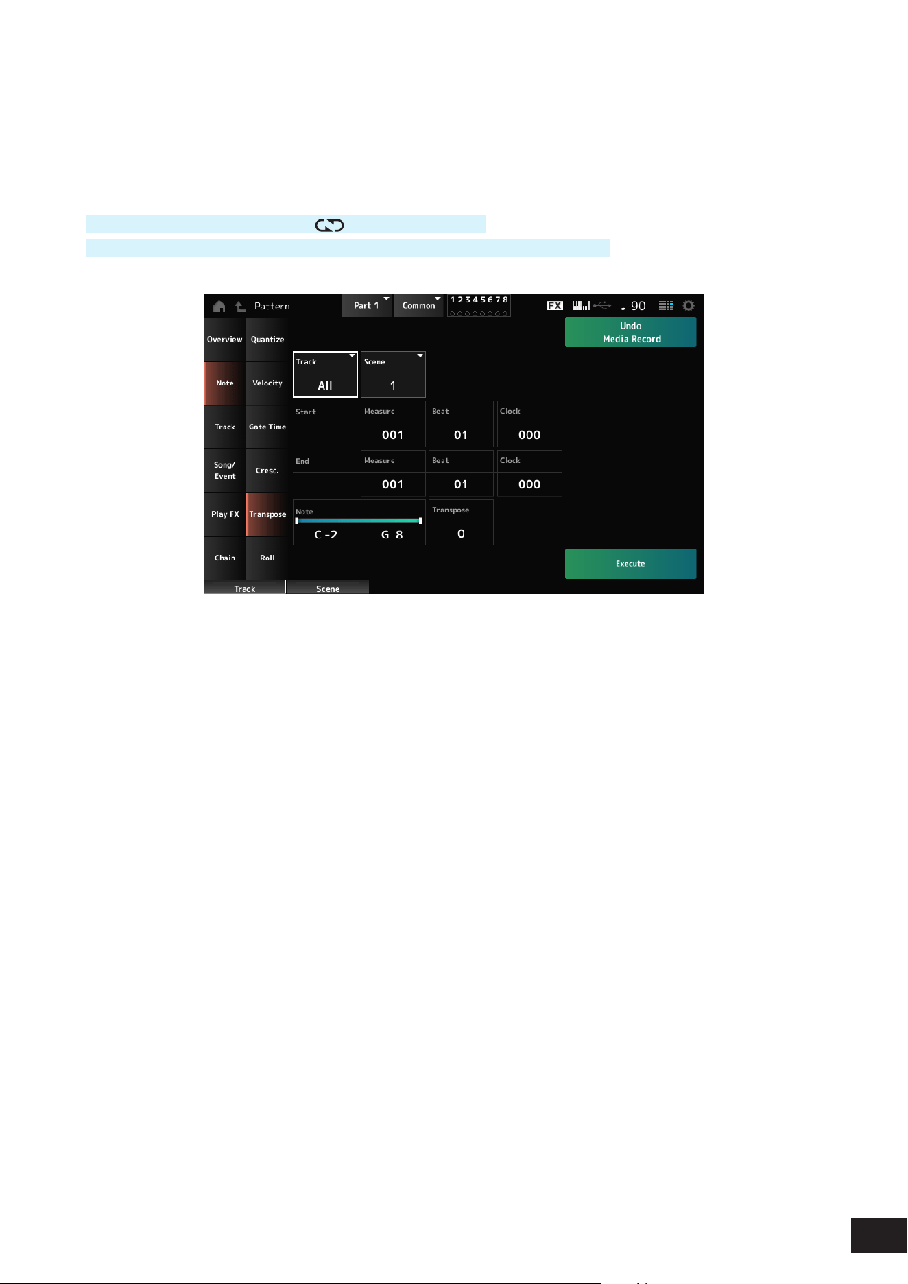
117
MODX M Operation Manual
Transpose
This Job lets you change the key or pitch of the notes in the specied range.
NOTE
When transposed, notes set in the range beyond C–2 to G8 are automatically moved to t within C–2 to G8.
Operation
[
] (Play) button
→
Pattern
→
[EDIT/ ]
→
Note
→
Transpose
[PERFORMANCE (HOME)]
→
Play/Rec
→
Pattern
→
Edit/Job
→
Note
→
Transpose
Note
Species the range of keys (notes) for transposing.
Tap to open the context menu and then set the Keyboard to On so that you can use the keys on the keyboard.
Settings: C−2–G8
Transpose
Sets the range of notes to shift in semitones.
A setting of +12 transposes up one octave, while a setting of −12 transposes down an octave. The value 0 produces no
change.
Settings: −127– 0 –+127

118
MODX M Operation Manual
Roll
This Job creates a series of repeated notes (like a drum roll) over the specied range.
Operation
[
] (Play) button
→
Pattern
→
[EDIT/ ]
→
Note
→
Roll
[PERFORMANCE (HOME)]
→
Play/Rec
→
Pattern
→
Edit/Job
→
Note
→
Roll
Track
Settings: 1–16
Start Step
Sets the size of the step (i.e., the number of clocks) between each note in the roll.
By setting a smaller value, you can play faster rolls. The clock specied here is for the beginning of the range.
Settings: 015–999
End Step
Sets the size of the step (i.e., the number of clocks) between each note in the roll.
By setting a smaller value, you can play faster rolls. The clock specied here is for the end of the range.
Settings: 015–999
Note
Sets the notes for rolls.
Tap to open the context menu and then set the Keyboard to On so that you can use the keys to set notes.
Settings: C−2–G8
Start Velocity
Sets the velocity for the strength of rolls. The velocity specied here is for the beginning of the range.
Settings: 001–127
End Velocity
Sets the velocity for the strength of rolls. The velocity specied here is for the end of the range.
Settings: 001–127
NOTE
By setting both Start Velocity and End Velocity, you can create crescendo or decrescendo for the rolls.
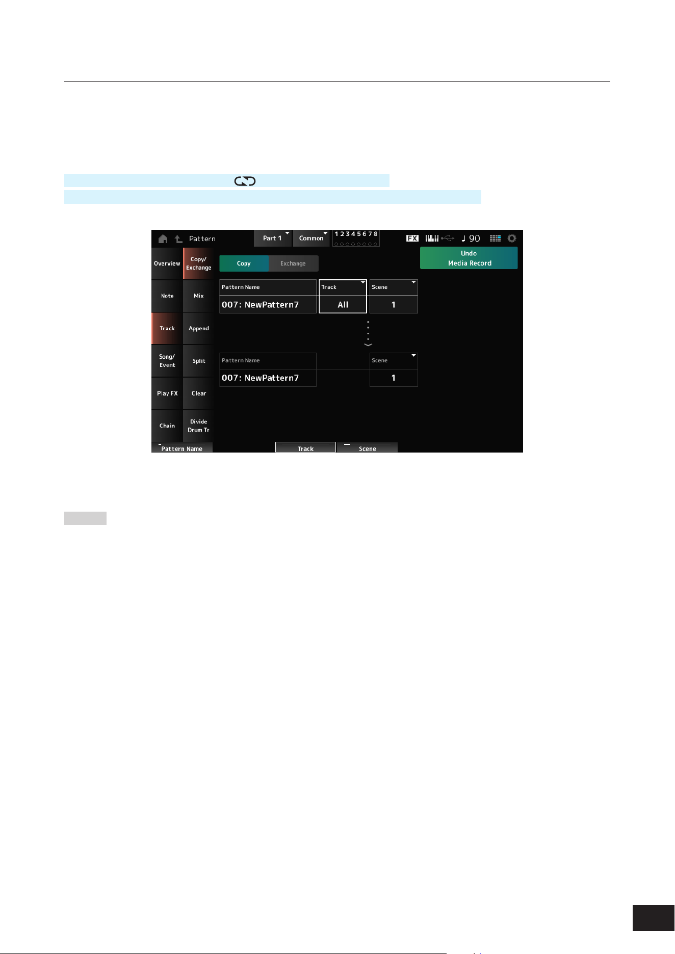
119
MODX M Operation Manual
Pattern Edit Track
Copy/Exchange
This Job copies data from a specied source track to the specied destination track or exchanges data between two
specied tracks.
Operation
[
] (Play) button
→
Pattern
→
[EDIT/ ]
→
Track
→
Copy/Exchange
[PERFORMANCE (HOME)]
→
Play/Rec
→
Pattern
→
Edit/Job
→
Track
→
Copy/Exchange
Copy
Copies data from the specied track to another track.
NOTICE
When Copy Track is carried out, the existing data on the
destination track will be overwritten and lost.
Exchange
Exchanges data between two tracks.
Pattern Name *Source
Species the Pattern to copy from.
Track *Source
Species the track to copy from.
Settings: All, 1–16
Scene *Source
Species the Scene to copy from.
Settings: All, 1–8
Pattern Name *Destination
Species the Pattern to copy to.
Track *Destination
Species the track to copy to.
This parameter is not available when Source is set to All.
Settings: 1–16
Scene *Destination
Species the Scene to copy to.
This parameter is not available when Source is set to All.
Settings: 1–8
Copy Track
Executes a copy action.
NOTE
When Copy Track is carried out with the Track and Scene set to
All, the Chain data will also be copied.
Exchange Track
Executes an exchange.
NOTE
When Exchange Track is carried out with the Track and Scene
set to All, the Chain data will also be copied.
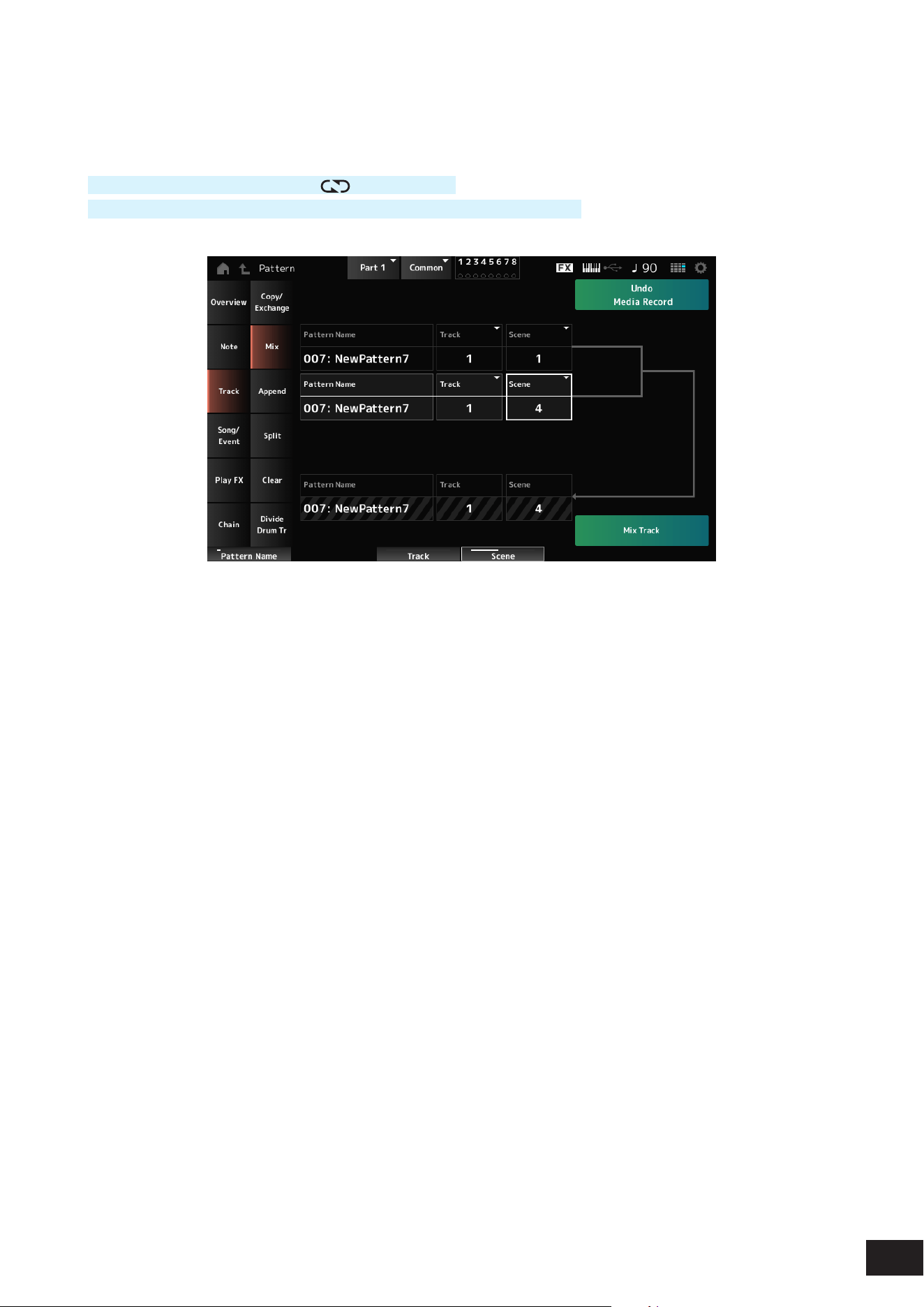
120
MODX M Operation Manual
Mix
Mixes (merges) the data from the specied track A and track B and places the result in track B.
Operation
[
] (Play) button
→
Pattern
→
[EDIT/ ]
→
Track
→
Mix
[PERFORMANCE (HOME)]
→
Play/Rec
→
Pattern
→
Edit/Job
→
Track
→
Mix
Pattern Name *Source A
Species the rst Pattern to mix.
Track *Source A
Species the track for the job.
Settings: 1–16
Scene *Source A
Species the Scene for the job.
Settings: All, 1–8
Pattern Name *Source B
Species the rst Pattern to mix.
Track *Source B
Species the track for the job.
Settings: 1–16
Scene *Source B
Species the Scene for the job.
This parameter is not available when Source A is set to
All.
Settings: 1–8
Pattern Name *Destination B
Shows the name of the Pattern to mix to.
Track *Destination B
Shows the track number for the job.
Scene *Destination B
Shows the Scene number for the job.
This parameter is not available when Source A is set to
All.
Mix Track
Executes a mix action.

121
MODX M Operation Manual
Append
Adds the data in the specied track to the end of another track.
Operation
[
] (Play) button
→
Pattern
→
[EDIT/ ]
→
Track
→
Append
[PERFORMANCE (HOME)]
→
Play/Rec
→
Pattern
→
Edit/Job
→
Track
→
Append
Pattern Name *Source
Species the Pattern to add from.
Track *Source
Sets the target track for the job.
Settings: All, 1–16
Scene *Source
Species the Scene for the job.
Settings: 1–8
Pattern Name *Destination
Species the Pattern to add to.
Track *Destination
Sets the target track for the job.
This parameter is not available when Source is set to All.
Settings: 1–16
Scene *Destination
Species the Scene for the job.
Settings: 1–8
Append Track
Executes an append action.

122
MODX M Operation Manual
Split
Splits the data of the specied track at the specied measure and moves the second half to another specied track.
Operation
[
] (Play) button
→
Pattern
→
[EDIT/ ]
→
Track
→
Append
[PERFORMANCE (HOME)]
→
Play/Rec
→
Pattern
→
Edit/Job
→
Track
→
Append
Pattern Name *Source
Species the Pattern to split.
Track *Source
Sets the target track for the job.
Settings: All, 1–16
Scene *Source
Sets the target scene for the job.
Settings: 1–8
Measure *Source
Species the measure at which the data is to be split.
Settings: 2–256
Pattern Name
Shows the Pattern to split into.
Track
Shows the track for the job.
Scene
Shows the Scene for the job.
Pattern Name *Destination
Species the Pattern to which the split data is to be sent.
Track *Destination
Sets the target track for the job.
This parameter is not available when Source is set to All.
Settings: 1–16
Scene *Destination
Sets the target scene for the job.
Settings: 1–8
Spilt Track
Executes a split action.

123
MODX M Operation Manual
Clear
Deletes data of the specied track.
Operation
[
] (Play) button
→
Pattern
→
[EDIT/ ]
→
Track
→
Clear
[PERFORMANCE (HOME)]
→
Play/Rec
→
Pattern
→
Edit/Job
→
Track
→
Clear
Pattern Name
Species the pattern to delete.
Track
Species the track for the job.
Settings: All, 1–16
Scene
Species the Scene for the job.
Settings: All, 1–8
Clear Track
Executes a clear action.
NOTE
When Clear Track is carried out with the Track and Scene set to All, the Chain data will also be deleted.
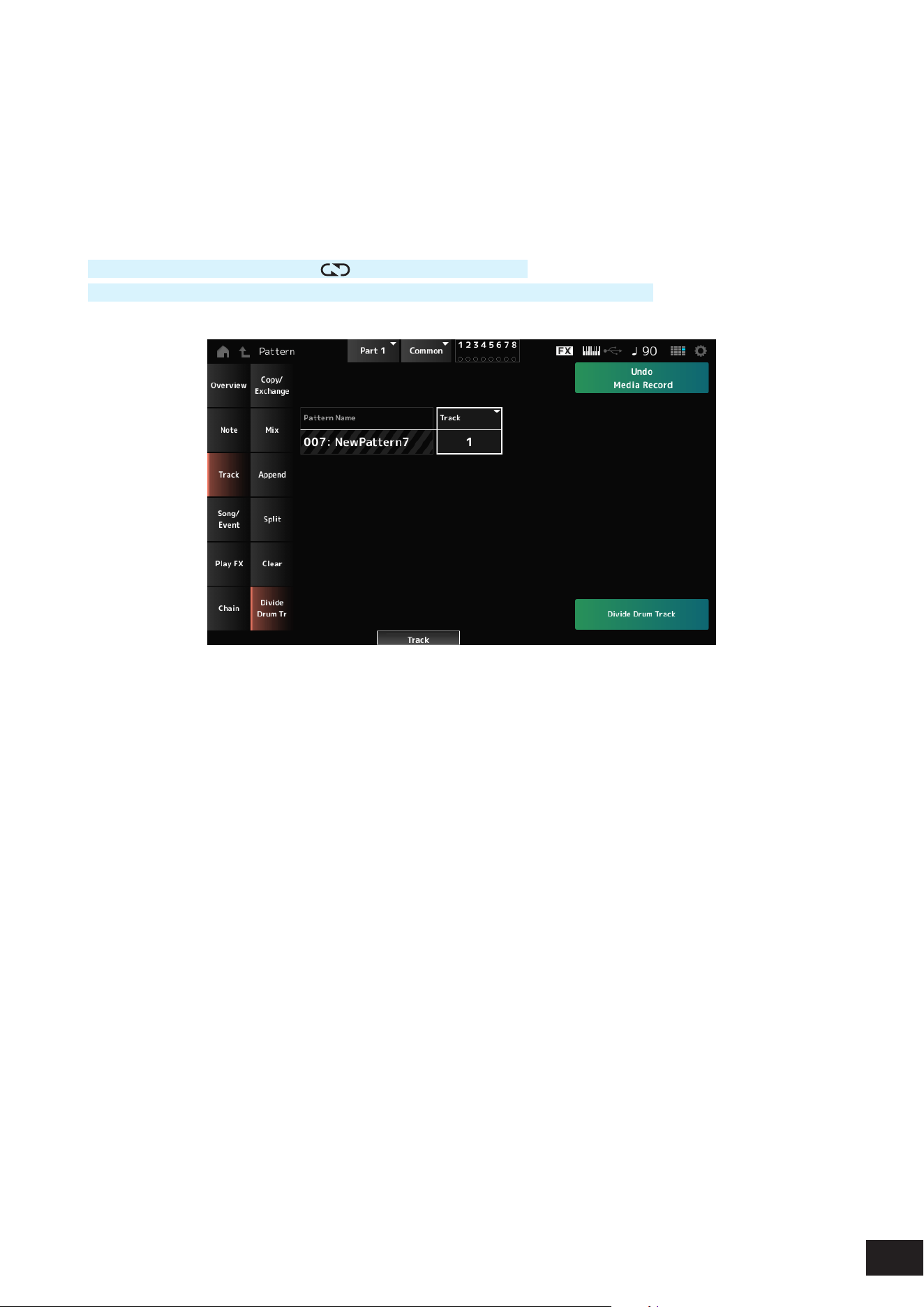
124
MODX M Operation Manual
Divide Drum Tr (Divide Drum Track)
Takes the recorded drums from the specied track and assigns each Instrument (individual percussion instrument in the
drum set) to Tracks 9 to 16.
NOTE
When there is existing data on Tracks 9 to 16 and Parts 9 to 16, carrying out the Divide Drum Track operation will overwrite the existing
data. Undo and Redo cannot be used with this operation.
Operation
[
] (Play) button
→
Pattern
→
[EDIT/ ]
→
Track
→
Divide Drum Tr
[PERFORMANCE (HOME)]
→
Play/Rec
→
Pattern
→
Edit/Job
→
Track
→
Divide Drum Tr
Pattern Name
Sets the target pattern for the job.
Track
Sets the target track for the job.
Settings: 1–16
Divide Drum Track
Executes a drum track divide action.
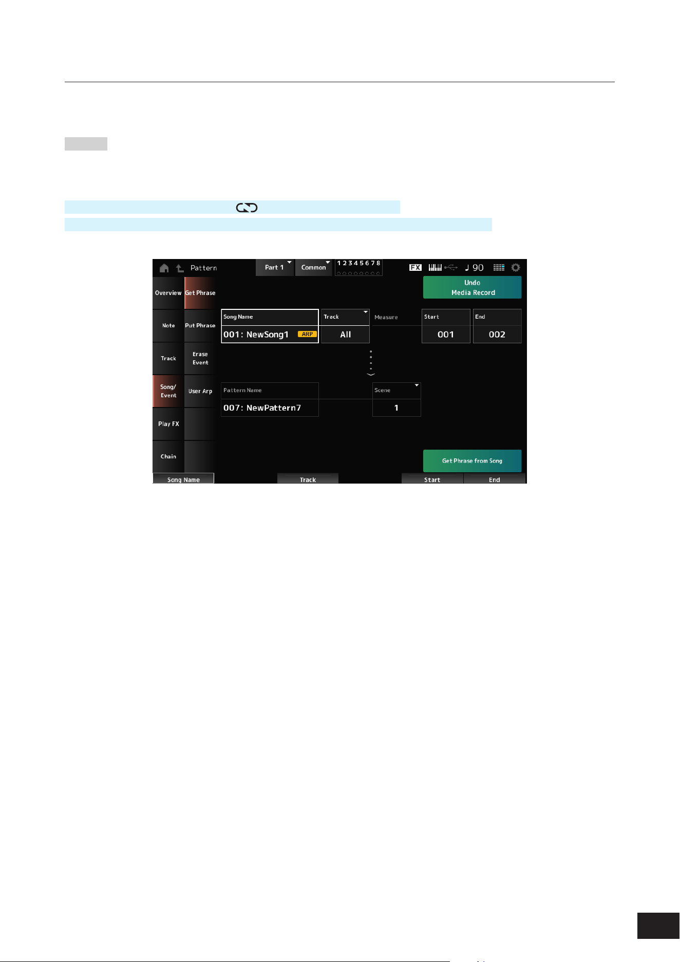
125
MODX M Operation Manual
Pattern Edit Song/Event
Get Phrase
Copies a specic section of the Song to the specied track.
NOTICE
The data at the copy destination will be overwritten and lost.
Operation
[
] (Play) button
→
Pattern
→
[EDIT/ ]
→
Song/Event
→
Get Phrase
[PERFORMANCE (HOME)]
→
Play/Rec
→
Pattern
→
Edit/Job
→
Song/Event
→
Get Phrase
Song Name
Species the Song to copy from.
Track *Source
Sets the target track for the job.
Settings: All, 1–16
Start Measure
Sets the target starting measure for the job.
Settings: 001–998
End Measure
Sets the target ending measure for the job.
Settings: 002–999
Pattern Name
Species the Pattern to copy to.
Track *Destination
Species the track to copy to.
This parameter is not available when Source is set to All.
Settings: 1–16
Scene
Species the Scene to copy to.
Settings: 1–8
Get Phrase from Song
Copies a phrase.
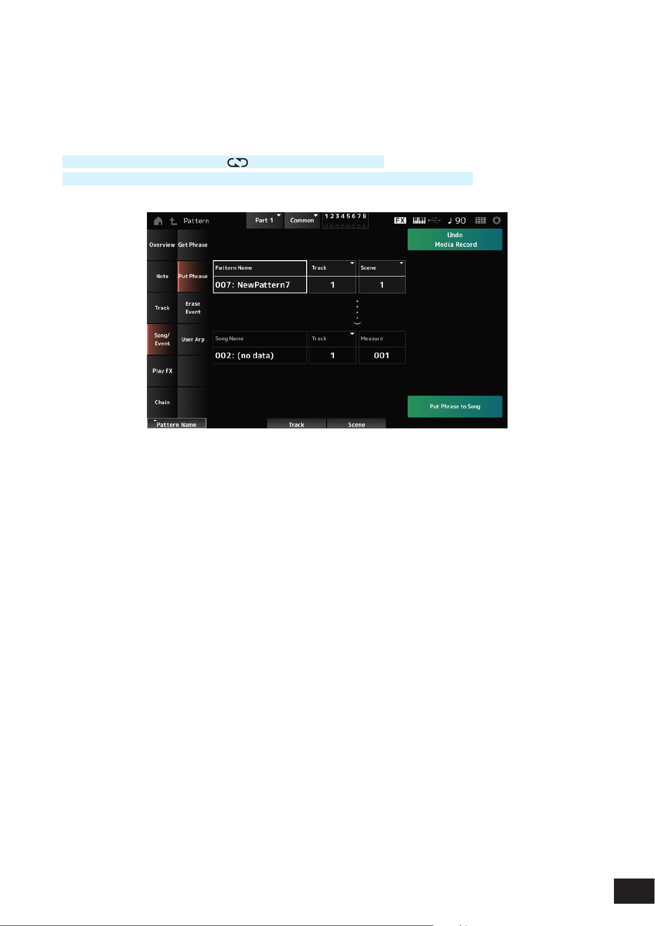
126
MODX M Operation Manual
Put Phrase
Copies the specied measures of the specied Pattern track to the specied Song track.
NOTE
The copied data will be merged into the existing data on the destination track.
Operation
[
] (Play) button
→
Pattern
→
[EDIT/
]
→
Song/Event
→
Put Phrase
[PERFORMANCE (HOME)]
→
Play/Rec
→
Pattern
→
Edit/Job
→
Song/Event
→
Put Phrase
Pattern Name
Species the Pattern to copy from.
Track *Source
Sets the target track for the job.
Settings: 1–16
Scene
Sets the target scene for the job.
Settings: 1–8
Song Name
Species the Song to copy to.
Track *Destination
Sets the target track for the job.
Settings: 1–16
Measure
Species the measure to copy to.
Settings: 001–999
Put Phrase to Song
Copies a phrase.
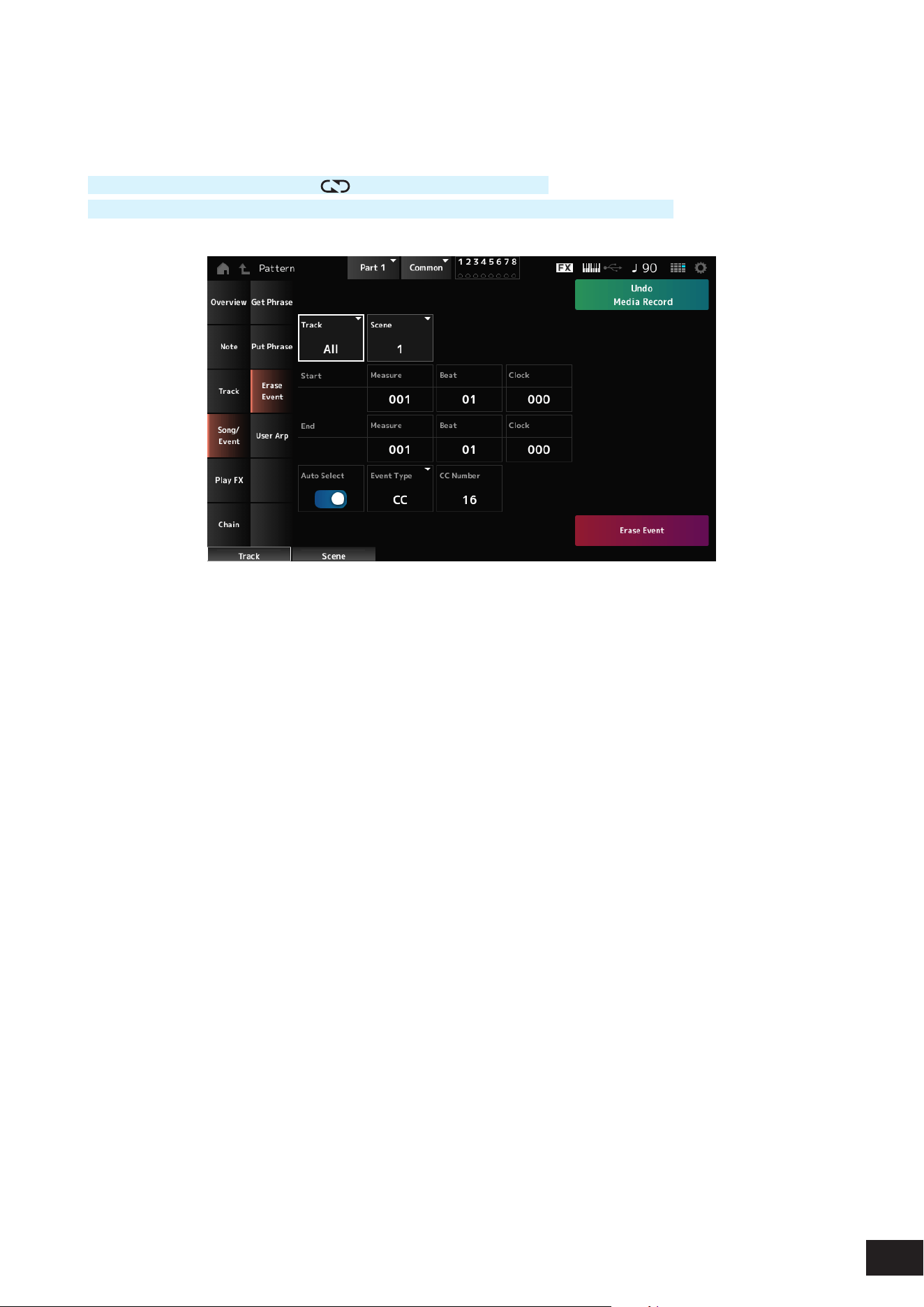
127
MODX M Operation Manual
Erase Event
Erases the event.
Operation
[
] (Play) button
→
Pattern
→
[EDIT/ ]
→
Song/Event
→
Erase Event
[PERFORMANCE (HOME)]
→
Play/Rec
→
Pattern
→
Edit/Job
→
Song/Event
→
Erase Event
Many of the parameters are the same as Pattern Edit Note
→
Quantize.
Auto Select
Switches the Auto Select setting of the Event Type on or off.
When this is set to On, you can simply move the controller whose data you wish to erase, and the corresponding
controller’s event will automatically be set for Event Type.
Settings: Off, On
Event Type
Species the type of event you wish to erase.
Settings: Note, Poly, CC, NRPN, RPN, PC, AfterTouch, PitchBend, Superknob, SysEx, All
CC Number
Displayed when the Event Type is set to CC. Specify the Control Change number of the event to erase.
Settings: All, 1–127
Erase Event
Executes the event deletion.

128
MODX M Operation Manual
User Arp (User Arpeggio)
Registers the data in the specied measures of the Scene as a User Arpeggio.
Operation
[
] (Play) button
→
Pattern
→
[EDIT/ ]
→
Song/Event
→
User Arp
[PERFORMANCE (HOME)]
→
Play/Rec
→
Pattern
→
Edit/Job
→
Song/Event
→
User Arp
Scene
Species the Scene for the job.
Settings: 1–8
Start Measure
Species the starting measure position for the job.
Settings: 1–256
End Measure
Species the ending measure position for the job.
Settings: 2–257
Arp (Arp Number)
Sets the Arpeggio Number of the User Arpeggio for conversion.
Initially, the next unused number will be set.
Keep in mind that if you change this to a number already being used, the Arpeggio will be overwritten, meaning that you
will lose the existing User Arpeggio for that number.
Settings: 1–256
Category (Arpeggio Category)
Sub Category (Arpeggio Sub Category)
Sets the Main and Sub categories of the converted Arpeggio.
Settings: Refer to the Data List
Name (Arpeggio Name)
Give the User Arpeggio a name. You can use up to 20 alphanumeric characters.
Track
Sets the track number to convert from for each Arpeggio track.
Settings: Off, 1–16

129
MODX M Operation Manual
Convert Type
Select the method for converting MIDI sequence data recorded in the track into an arpeggio.
You can use a different Convert Type for each Arpeggio track.
Settings: Normal, Fixed, Org Notes
Normal: The Arpeggio is played back at the same octave as the recorded MIDI Sequence.
Fixed: The recorded MIDI sequence is played back the same way no matter how you play the keyboard.
Org Notes: Basically the same as Fixed, but the MIDI sequence changes according to the chords you play on the keyboard
Org Notes Root
Sets the root note when the Convert Type of any track is set to Org Notes.
This parameter is not available when no track is set to Org Notes.
Settings: C−2–G8
Store As User Arp (Store As User Arpeggio)
Converts the Pattern to a User Arpeggio using the settings on the screen.
This parameter is not available when all Track are set to Off.
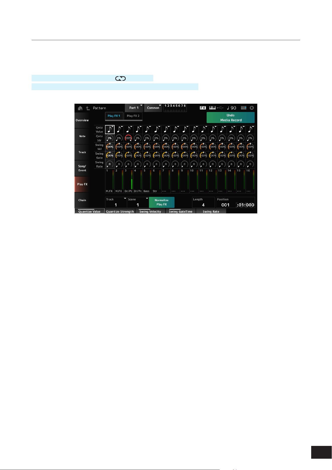
130
MODX M Operation Manual
Pattern Edit Play FX (Play Effects)
Applies effects to the MIDI sequence during Pattern playback. Sets the range and level of the effect for each parameter
of the specied track.
Operation
[
] (Play) button
→
Pattern
→
[EDIT/ ]
→
Play FX
[PERFORMANCE (HOME)]
→
Play/Rec
→
Pattern
→
Edit/Job
→
Play FX
Common
Track
Species the track to be normalized.
Settings: All, 1–16
Scene
Species the Scene to be normalized.
Settings: All, 1–8
Normalize Play FX
Fixes the effect specied in Play FX to the MIDI data.
Length
Sets the sequence length of the selected Scene.
Position
Shows the current position for the Scene playback, and lets you specify the playback position.
Settings: 001–256

131
MODX M Operation Manual
Play FX1
Controls Qntz Value, Qntz Str, Swing Vel, Swing Gate, and Swing Rate.
Qntz Value (Quantize Value)
Sets the quantization resolution (or a note to be used as a base for the quantization).
Settings: Off, 60 (thirty-second note), 80 (sixteenth note triplet), 120 (sixteenth note), 160 (eighth note triplet), 240 (eighth note),
320(quarter note triplet), 480 (quarter note)
Qntz Str (Quantize Strength)
Sets the “magnetic strength” of the quantization.
When this parameter is set to 100%, all notes will move to the position specied in Qntz Value (Quantize Value) while a
setting of 0% results in no quantization.
Settings: 0%–100%
Swing Vel (Swing Velocity Rate)
Changes the velocity of the even-numbered beats (backbeats) counted from the value specied in Qntz Value (Quantize
Value) to add a swing feel to the rhythms. This parameter is not available when Qntz Value (Quantize Value) is set to Off.
Settings: 0%–200%
Swing Gate (Swing Gate Time Rate)
Changes the gate time (or the actual time for the note to be played) of the even-numbered beats (backbeats) counted
from the value specied in Qntz Value (Quantize Value) to add a swing feel to the rhythms. This parameter is not available
when Qntz Value (Quantize Value) is set to Off.
Settings: 0%–200%
Swing Rate (Swing Offset)
Changes the timing of the even-numbered beats (backbeats) counted from the value specied in Qntz Value (Quantize
Value) to add a swing feel to the rhythms. This parameter is not available when Qntz Value (Quantize Value) is set to Off.
Settings: 0 to half of Qntz Value (Quantize Value)
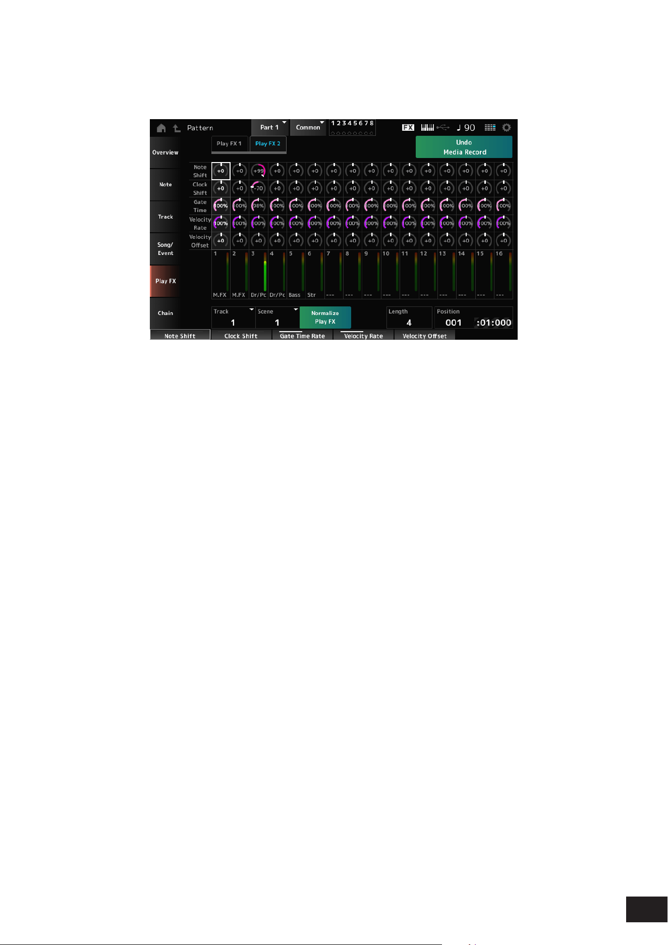
132
MODX M Operation Manual
Play FX2
Controls Note Shift, Clock Shift, Gate Time, Velocity Rate, and Velocity Offset.
Note Shift
Adjusts the pitch in semitones.
Settings: −99–+0–+99
Clock Shift
Shifts the timing of the notes back or forward in clock increments.
Settings: −120 –+0–+120
Gate Time
Changes the gate time (the actual time for the sound of the note to be generated) of the note events.
Settings: 0%–200%
Velocity Rate
Changes the velocity by the specied percentage.
Settings: 0%–200%
Velocity Offset
Increases or decreases velocity by the specied value.
Settings: −99–+0–+99
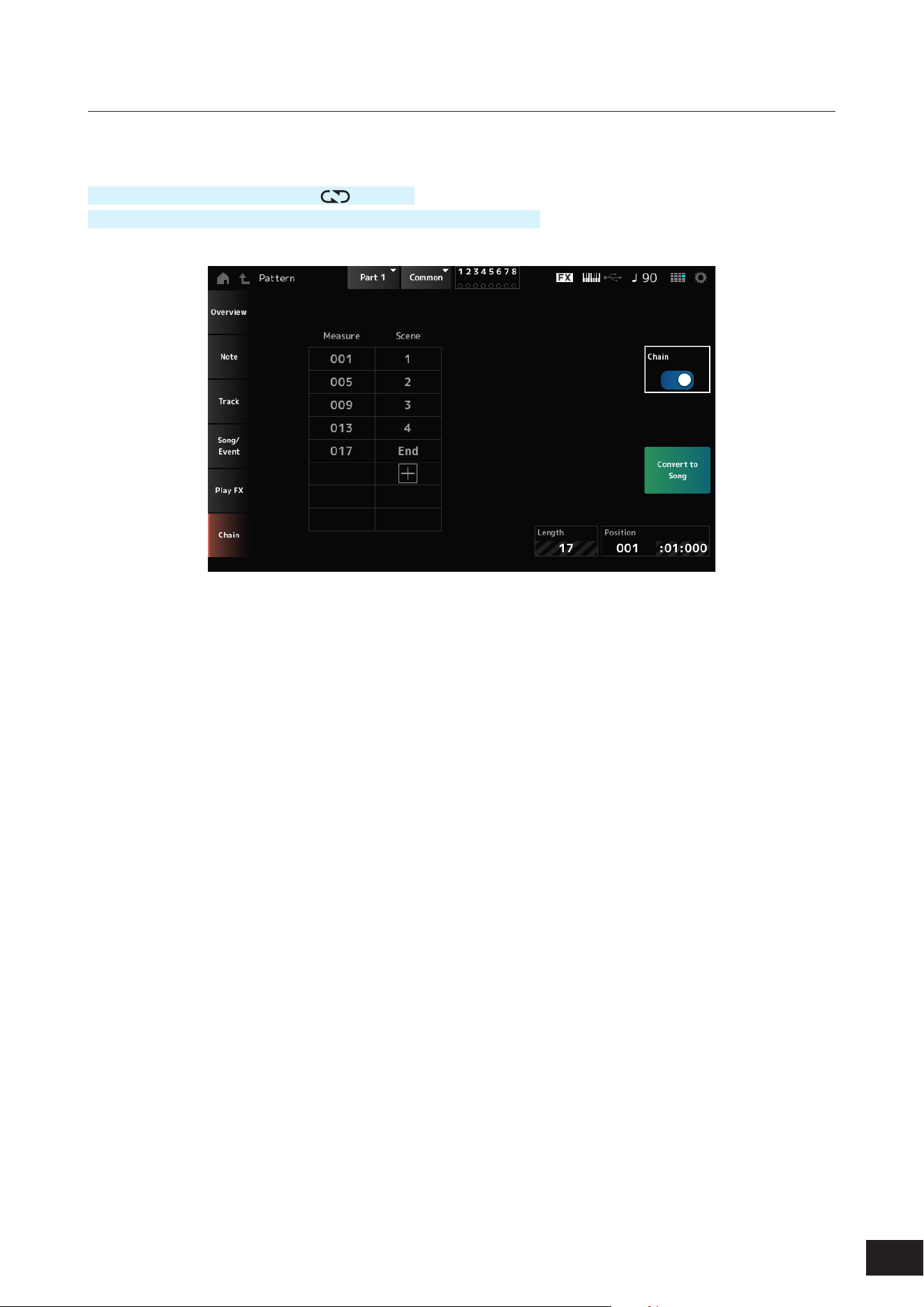
133
MODX M Operation Manual
Pattern Edit Chain
This Job chains Scenes for playback.
Operation
[
] (Play) button
→
Pattern
→
[EDIT/ ]
→
Chain
[PERFORMANCE (HOME)]
→
Play/Rec
→
Pattern
→
Edit/Job
→
Chain
Chain
Enables chain playback.
Settings: Off, On
Measure
Species the starting measure position for Scene playback.
Settings: 001–999
Scene
Sets the Scene to play back at the specied Measure.
Settings: 1–8, End
Page
When there are more than eight rows for the list of Measure and Scene, the up or down arrow will be shown.
Convert to Song
Saves the chain as a Song.
Length
Shows the length of the entire sequence.
Position
Shows the current position of chain playback, and lets you specify the playback position.
Settings: 001–999
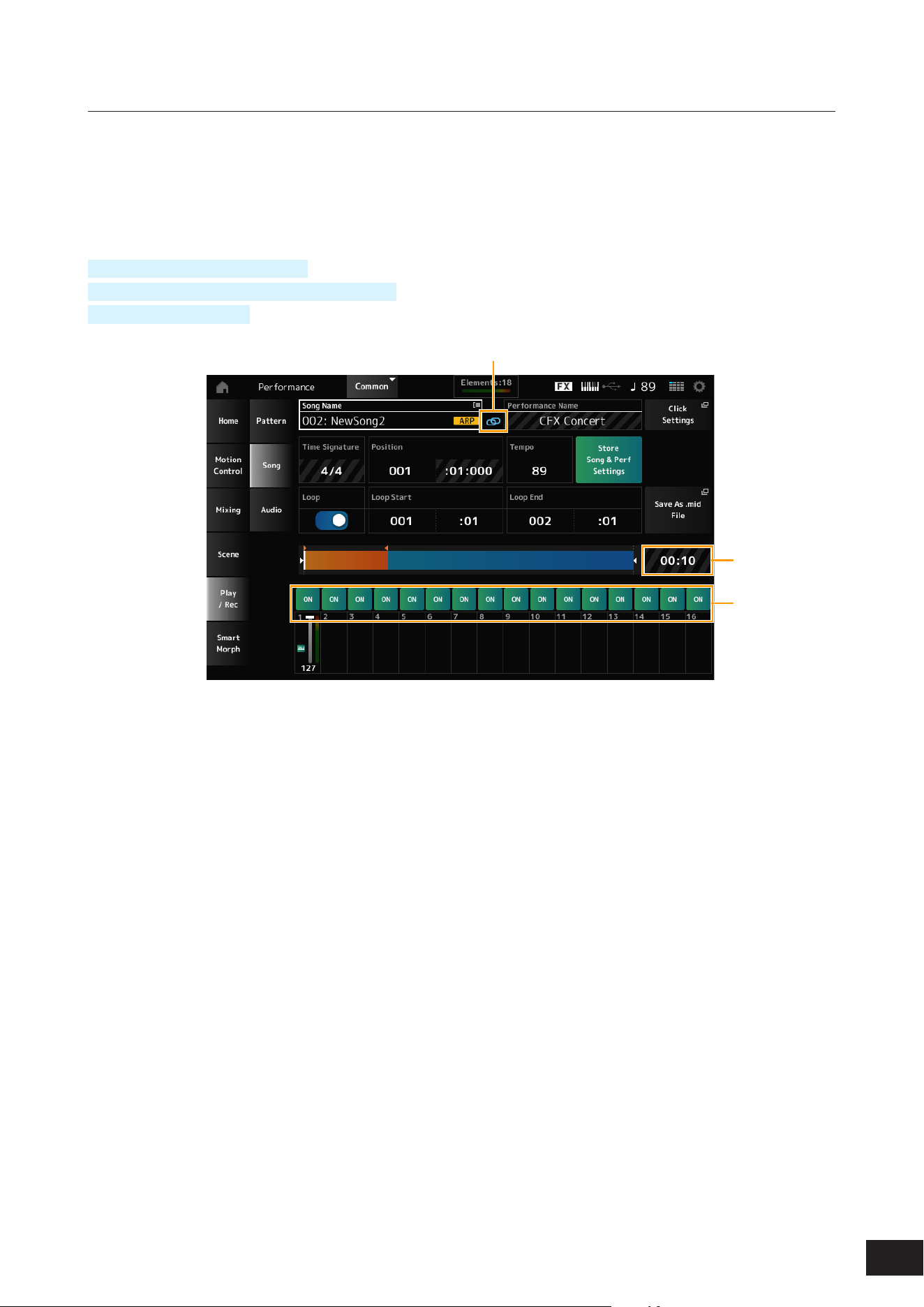
134
MODX M Operation Manual
Song
In the Song screen, you can record your keyboard performance in MIDI Song, and play back the Song.
The data of both the keyboard performance and the operation of controllers and knobs is recorded to the MIDI track.
You can also select Arpeggio playback to be recorded to the Song.
Playback and playback standby
Operation
[SONG/PATTERN] button
→
Song
[PERFORMANCE (HOME)]
→
Play/Rec
→
Song
[
] (Play) button
→
Song
(1)
(2)
(3)
(1) Link Icon
(2) Song Length
(3) Track Play Switch
Song Name
Shows the name of the selected Song.
Tap to display the context menu for Load, Rename, New Song, and User Arp.
You can select a Song by using the [INC/YES] and [DEC/NO] buttons when the cursor is on the Song Name.
Performance Name
Shows the name of the selected Performance.
NOTE
The blue ag will be shown at the top right of the Performance Name when you change a parameter in the Performance.
Link Icon
The Link Icon is shown if the Performance used for recording the Song and the selected Performance are the same. If
not, a broken Link Icon will be shown.
Click Settings
This calls up the Tempo Settings screen.
Time Signature
Shows the meter for the Pattern.

135
MODX M Operation Manual
Position
Sets the position for starting playback and recording, as well as the current playback position.
The number shown on the left is the measure, and the numbers shown on the right are the beats and ticks.
Tempo
Sets the tempo for Song playback.
Settings: 5–300
Loop
Sets Loop playback on or off.
When set to On, the playback of a section between the Loop Start and Loop End points will be repeated.
Settings: Off, On
Loop Start
Loop End
Sets the section for Loop playback. The number shown on the left is the measure, and the number shown on the right is
the beat. This parameter is not available when Loop is set to Off.
Store Song & Perf Settings (Store Song and Performance Settings)
Saves the link between the edited Songs and the Performance used.
NOTE
If you have edited the Performance parameters, you will also need to store the Performance.
Save As .mid File
Pressing this button calls up the Save screen, allowing you to save the Song as a le.
Not available in the following situations.
• For a new recording (when there is no Song)
• During playback
• When recording standby is enabled
• During recording
Song Length
Shows the length of the entire sequence.
Track Play Switch
Turns playback of each track on or off.
Settings: Off, On
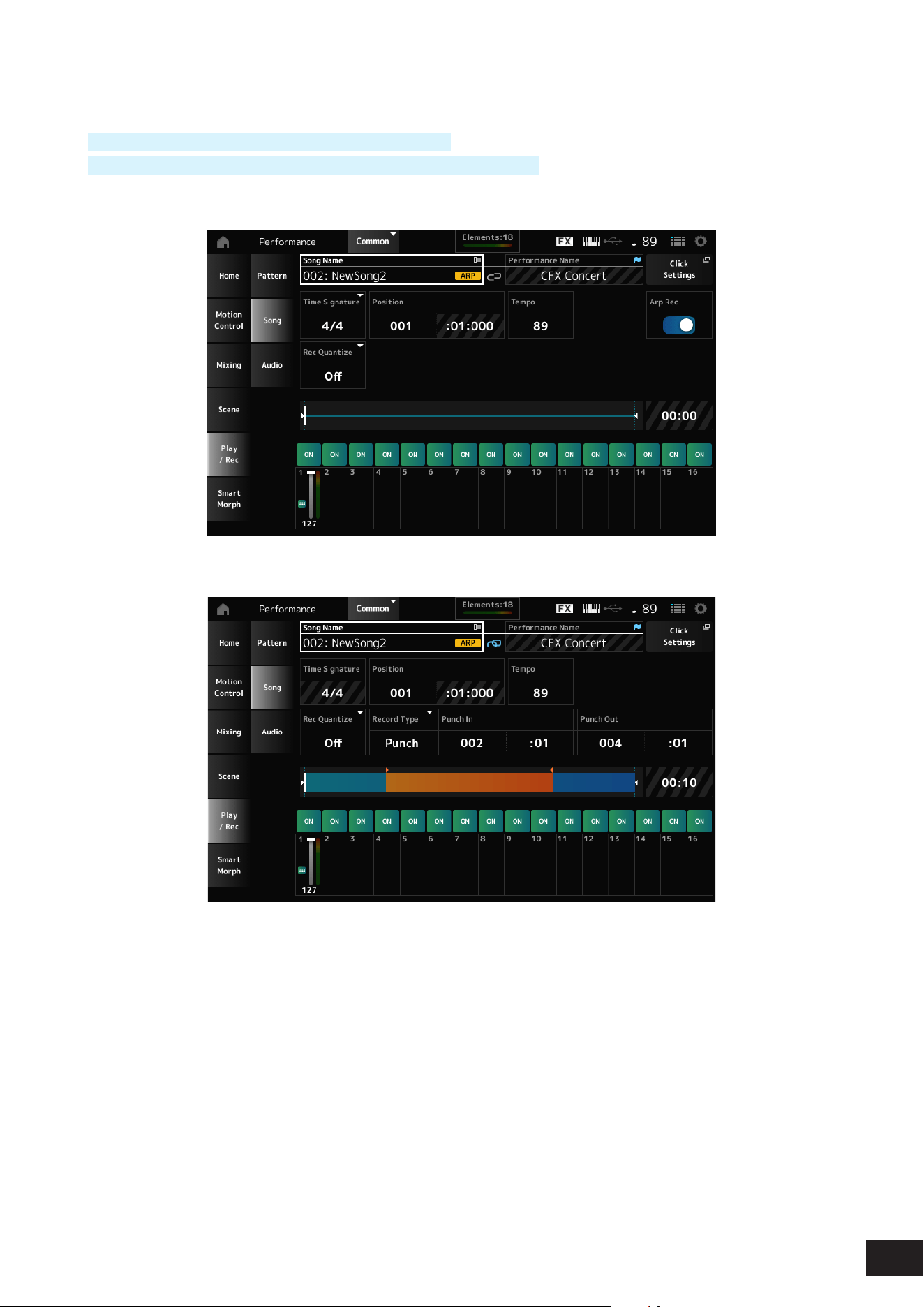
136
MODX M Operation Manual
Recording and recording standby
Operation
[SONG/PATTERN] button
→
Song
→
[
] (Record) button
[PERFORMANCE (HOME)]
→
Play/Rec
→
Song
→
[
] (Record) button
New recording
When something has already been recorded
Time Signature
Shows the meter for the Song.
Settings: 1/16–16/16, 1/8–16/8, 1/4–8/4
Rec Quantize
Quantize is a function that corrects the recorded notes to be on the exact fraction of the beat (in note values).
Settings: Off, 60 (thirty-second note), 80 (sixteenth note triplet), 120 (sixteenth note), 160 (eighth note triplet), 240 (eighth note),
320(quarter note triplet), 480 (quarter note)

137
MODX M Operation Manual
Record Type
Selects a record type for the tracks already recorded.
This parameter is not available for a new recording.
Settings: Replace, Overdub, Punch
Replace: Overwrite and record in real-time. The existing data will be lost
Overdub: Overdub and record in real-time. The existing data will not be lost
Punch: Re-record a section and record in real-time. This overwrites the existing data of a specied section
Punch In
Sets the Punch in point (specic measure and beat at which to start re-recording).
This parameter is available only when Record Type is set to Punch.
Punch Out
Sets the Punch out point (specic measure and beat at which to end re-recording).
This parameter is available only when Record Type is set to Punch.
Arp Rec
When set to On, the results of Arpeggio playback are recorded. When set to Off, only the keyboard performance is
recorded.
This parameter can be set for recording a new Song. The setting cannot be changed after the recording.
To add something to the Song recorded with Arp Rec set to Off, only Replace can be used for Record Type.
Settings: Off, On
NOTE
With the Song with Arp Rec set to Off, you can select a different Arpeggio for playback by changing the Arpeggio selection in the
Performance.
Undo Media Record
Cancels the previous action and returns to the previous state.
This button becomes available when one or more Jobs have been used after a sequence has been recorded.
Redo Media Record
Restores the recording that has been canceled by Undo Media Record. Enabled when Undo Media Record was used.
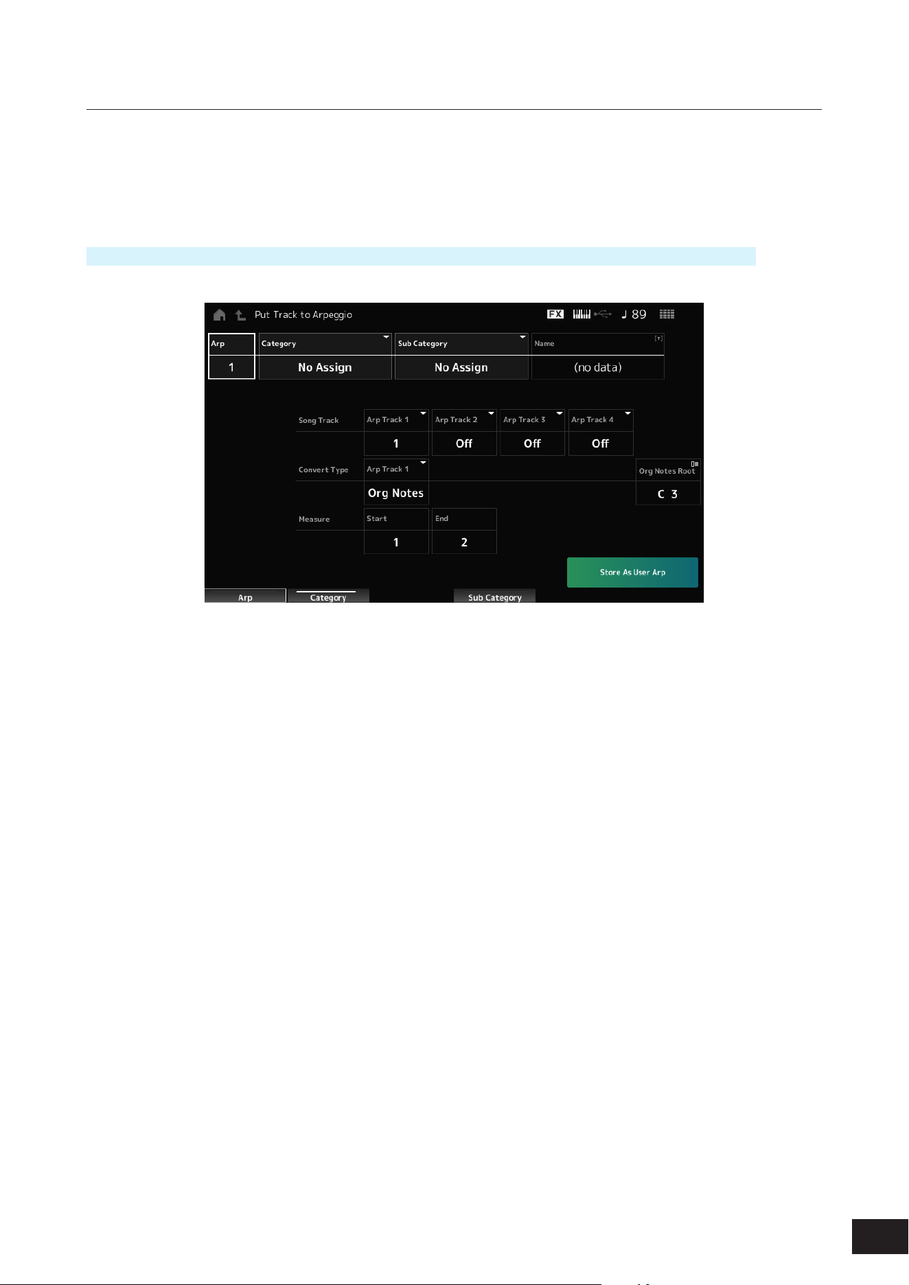
138
MODX M Operation Manual
Put Track to Arpeggio
Converts the selected Song to a User Arpeggio.
Up to 16 different notes can be converted. (All notes with the same Note Number are counted as one.)
Make sure to use only up to 16 notes for a Song if you wish to convert it to a User Arpeggio, especially when you use
multiple tracks.
Operation
[SONG/PATTERN] button
→
Tap on Play/Rec
→
Song
→
Song Name to open the context menu
→
User Arp
Arp (Arpeggio Number)
Sets the Arpeggio Number of the User Arpeggio for conversion.
Initially, the next unused number will be set.
Keep in mind that if you change this to a number already being used, the Arpeggio will be overwritten, meaning that you
will lose the existing User Arpeggio for that number.
Settings: 1–256
Category (Arpeggio Category)
Sub Category (Arpeggio Sub Category)
Sets the Main and Sub categories of the converted Arpeggio.
Settings: Refer to the Data List
Name (Arpeggio Name)
Sets the Arpeggio Name. You can use up to 20 alphanumeric characters.
Song Track
Sets the track number of the Song to convert from for each Arpeggio track.
Settings: Off, 1–16

139
MODX M Operation Manual
Convert Type
Selects how to convert the MIDI sequence recorded in the Song to the Arpeggio from three different settings.
You can use a different Convert Type for each Arpeggio track.
Settings: Normal, Fixed, Org Notes
Normal: The Arpeggio is played back at the same octave as the recorded MIDI Sequence
Fixed: The recorded MIDI sequence is played back the same way no matter how you play the keyboard.
Org Notes: Basically the same as Fixed, but the playback of the MIDI sequence changes according to the chords you play
on the keyboard
Org Notes Root (Original Notes Root)
Sets the root note when the Convert Type of any track is set to Org Notes.
This parameter is not available when no track is set to Org Notes.
Settings: C−2–G8
Start Measure
Sets the starting measure for the conversion.
Settings: 1–998
End Measure
Sets the ending measure for the conversion.
Settings: 2–999
Store As User Arp
Converts the Song to a User Arpeggio with the settings specied on this screen.
This button is disabled when all tracks are set to Off.
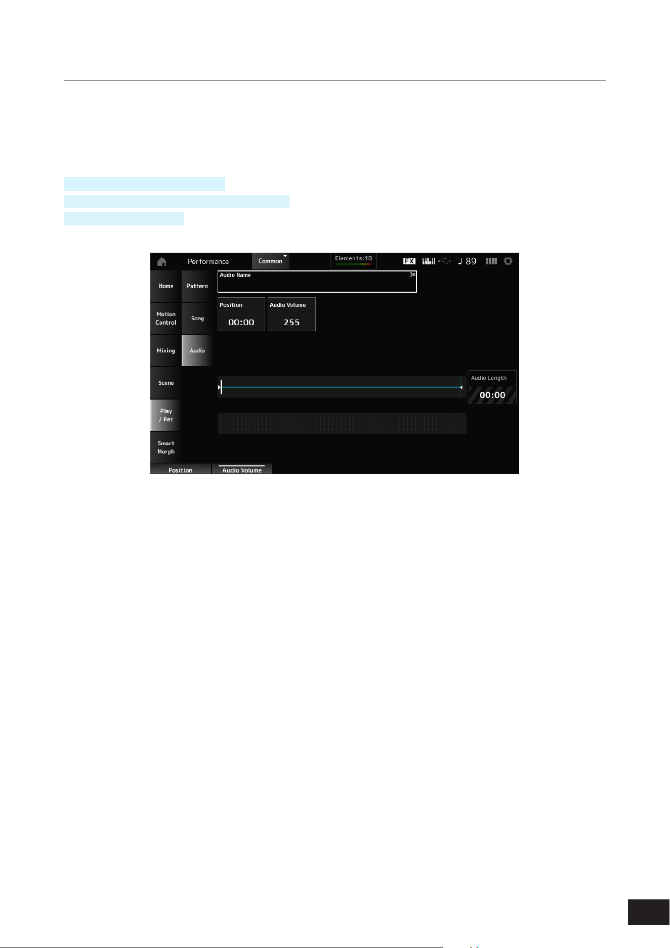
140
MODX M Operation Manual
Audio
On the Audio screen, you can record your keyboard performance as an audio le .wav (44.1-kHz, 24-bit stereo) to the USB
ash drive. The maximum recording time is 74 minutes, or up to the capacity of the recording device.
Playback and playback standby
Operation
[SONG/PATTERN] button
→
Audio
[PERFORMANCE (HOME)]
→
Play/Rec
→
Audio
[
] (Play) button
→
Audio
Audio Name
Shows the name of the selected Audio le.
Tap to display the context menu for Load.
Position
Sets the position for starting playback, as well as the current playback position.
Audio Volume
Sets the position for starting playback. This parameter is not available during recording.
Settings: 0–255
Audio Length
Shows the total length of the audio le.
Level meter
Shows the audio input and output level.
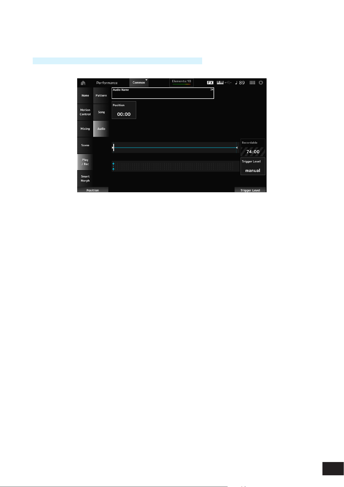
141
MODX M Operation Manual
Recording and recording standby
Operation
[PERFORMANCE (HOME)]
→
Play/Rec
→
Audio
→
[
] (Record) button
Recordable (Audio Recordable Time)
Shows the recordable time for audio. This parameter is shown only while recording standby is enabled.
Trigger Level
Selects how to start recording. This parameter is shown only while recording standby is enabled.
Settings: manual, 1–127
manual: Press the [
] (Play) button to start recording
1–127: After pressing the [
] (Play) button, recording will start when a signal exceeding the set value is input. The level set
here will be indicated by blue triangles in the level meter
NOTE
For best results, set Trigger Level as low as possible to capture the entire signal, but not so low as to record unwanted noise.
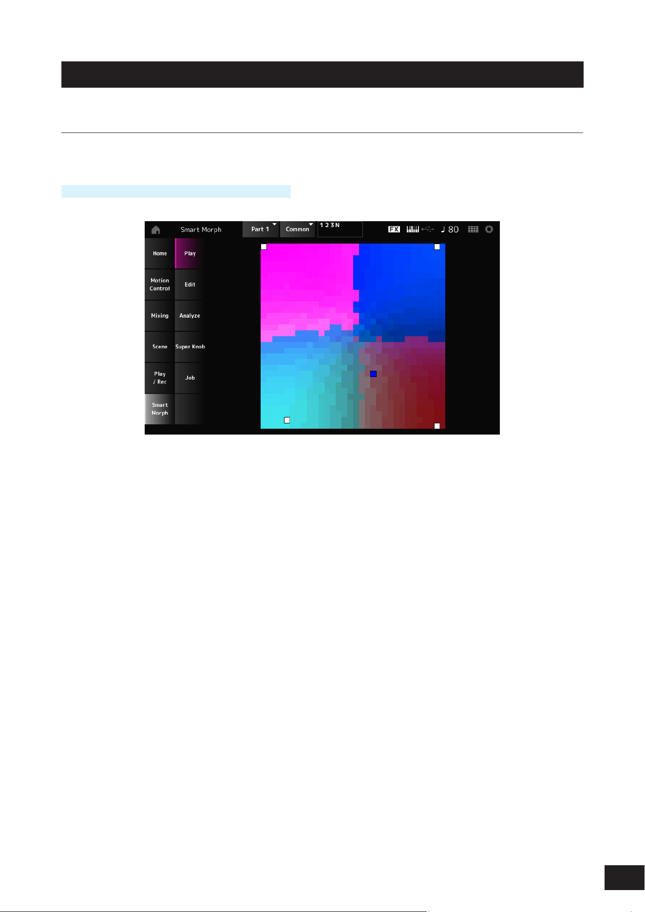
142
MODX M Operation Manual
Smart Morph
Play
Tap on the Smart Morph map, and create changes in the FM-X sound or AN-X sound on Part 1.
Operation
[PERFORMANCE (HOME)]
→
Smart Morph
→
Play
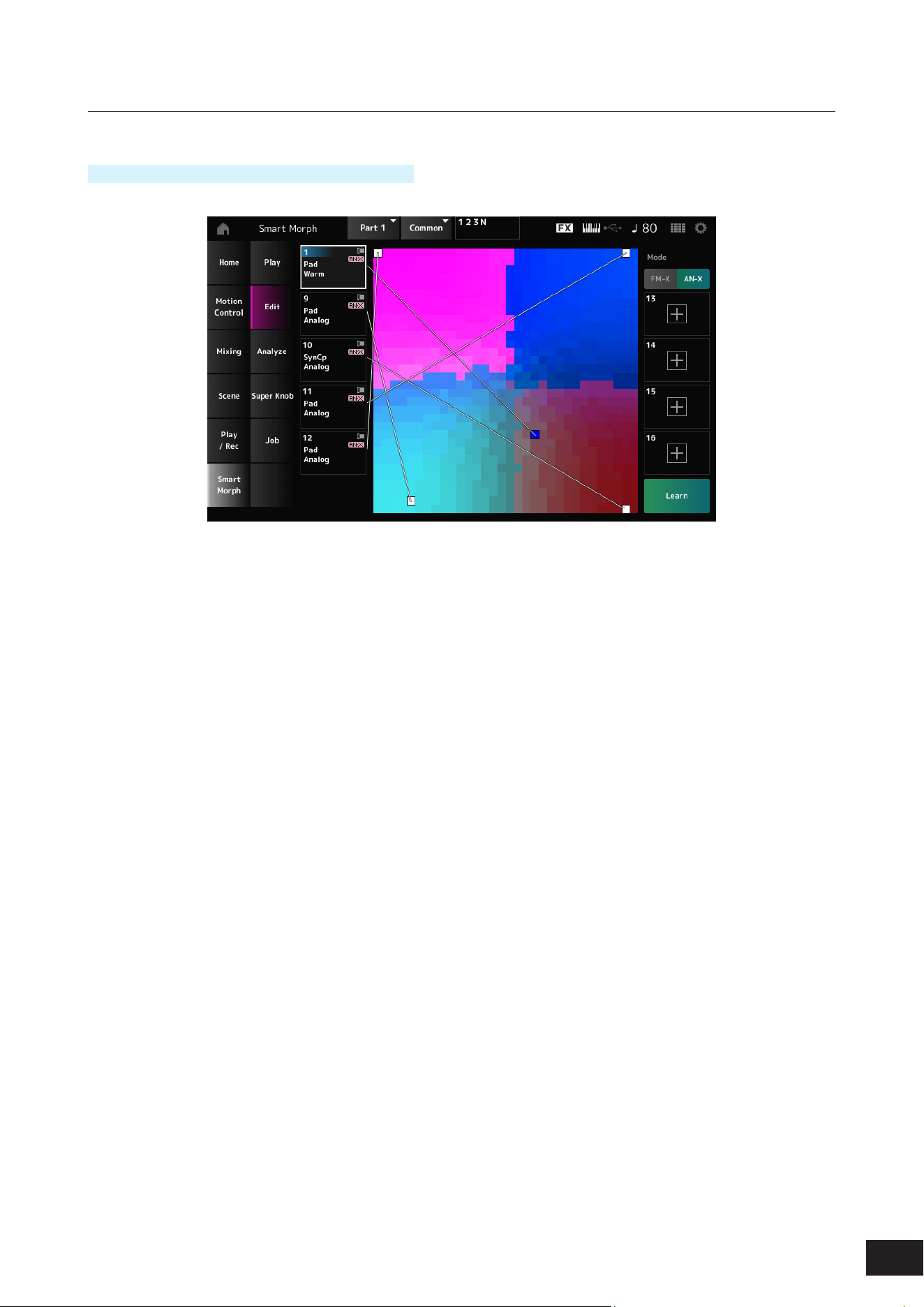
143
MODX M Operation Manual
Edit
Operation
[PERFORMANCE (HOME)]
→
Smart Morph
→
Edit
Unused Part
Tap to open the Part Category Search screen for selecting an FM-X sound or AN-X sound.
Part being used
Tap to display the context menu for Category Search, Edit, Property, etc.
Display
Selects the Part Main Category view or Part Name view for each Part.
Mode
Switches between FM-X and AN-X.
Settings: FM-X, AN-X
Learn
Tap the button to start machine learning (map creation).
This button will not be shown when there is no FM-X sound or AN-X sound on Parts 9 to 16.
Undo
Redo
After the Learn operation, the Undo button will be shown on the upper right.
Use the Undo button to restore the original map before using machine learning.
After the Undo operation, the Redo button will appear, and you can use it to restore the map before the Undo operation.
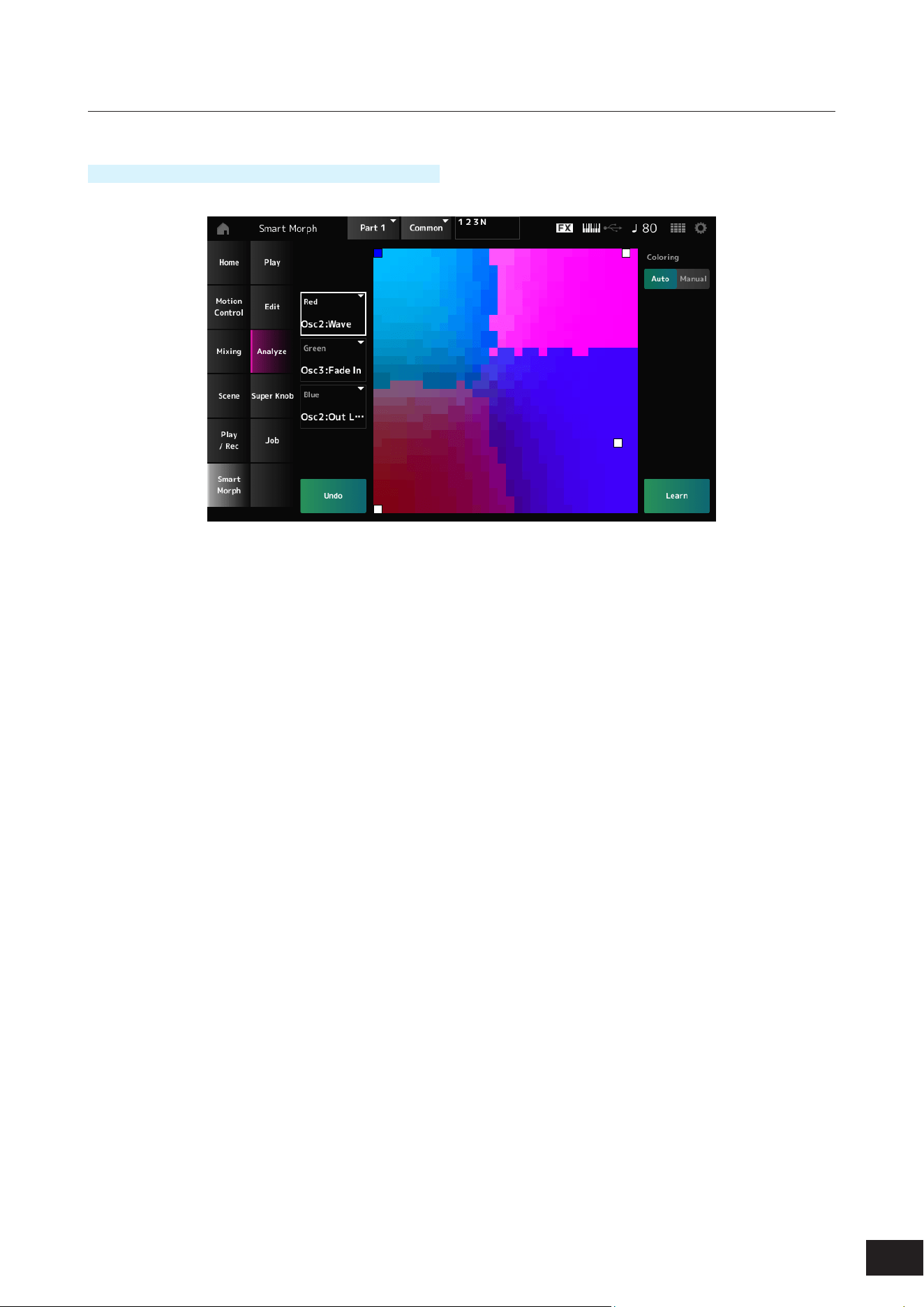
144
MODX M Operation Manual
Analyze
Operation
[PERFORMANCE (HOME)]
→
Smart Morph
→
Analyze
Red
Each dot on the map represents the parameter value indicating a degree or level as a shade of red.
Green
Each dot on the map represents the parameter value indicating a degree or level as a shade of green.
Blue
Each dot on the map represents the parameter value indicating a degree or level as a shade of blue.
NOTE
For the list of available Red, Green, and Blue parameters, see "Parameters that can be set for Red, Green, and Blue."
Coloring
When set to Auto, the Red, Green, and Blue are automatically reset for the Learn process.
When set to Manual, the Red, Green, and Blue are not automatically reset for the Learn process.
Settings: Auto, Manual
Learn
Tap the button to start machine learning (map creation).
Undo
Redo
After the Learn operation, the Undo button will be shown on the upper right.
Use the Undo button to restore the original map before using machine learning.
After the Undo operation, the Redo button will appear, and you can use it to restore the map before the Undo operation.
145
MODX M Operation Manual
Parameters that can be set for Red, Green, and Blue
• FM Common
Display Name Parameter Name
Random Pan Depth Random Pan Depth
Alternate Pan Alternate Pan Depth
Scaling Pan Depth Scaling Pan Depth
KeyOnDly Time Key On Delay Time Length
KeyOnDly Sync Key On Delay Tempo Sync Switch
KeyOnDly Note Key On Delay Note Length
Pitch/Vel Pitch Velocity Sensitivity
Random Pitch Depth Random Pitch Depth
Pitch/Key Pitch Key Follow Sensitivity
Pitch/Key Center Pitch Key Follow Sensitivity Center Note
PEG Initial Lvl PEG Initial Level
PEG Attack Lvl PEG Attack Level
PEG Decay 1 Lvl PEG Decay 1 Level
PEG Decay 2 Lvl PEG Decay 2 Level
PEG Release Lvl PEG Release Level
PEG Attack Tm PEG Attack Time
PEG Decay 1 Tm PEG Decay 1 Time
PEG Decay 2 Tm PEG Decay 2 Time
PEG Release Tm PEG Release Time
PEG Depth/Vel PEG Depth Velocity Sensitivity
PEG Depth PEG Depth
PEG Time/Key PEG Time Key Follow Sensitivity
2nd LFO Wave 2nd LFO Wave
LFO Speed 2nd LFO Speed
LFO Phase 2nd LFO Phase
LFO Delay 2nd LFO Delay Time
LFO Key On Reset 2nd LFO Key On Reset
LFO Pitch Mod 2nd LFO Pitch Modulation Depth
LFO Amp Mod 2nd LFO Amp Modulation Depth
LFO Filter Mod 2nd LFO Filter Modulation Depth
Algorithm Number Algorithm Number
Feedback Level Feedback Level
LFO Speed Range LFO Speed Range
LFO Ex Speed LFO Extended Speed
Filter Type Filter Type
Cutoff Filter Cutoff Frequency
Cutoff/Vel Filter Cutoff Velocity Sensitivity
Resonance / Width Filter Resonance/Width
Res/Vel Resonance Velocity Sensitivity
HPF Cutoff HPF Cutoff Frequency
Distance Distance
Filter Gain Filter Gain
FEG Hold Tm FEG Hold Time
146
MODX M Operation Manual
Display Name Parameter Name
FEG Attack Tm FEG Attack Time
FEG Decay 1 Tm FEG Decay 1 Time
FEG Decay 2 Tm FEG Decay 2 Time
FEG Release Tm FEG Release Time
FEG Hold Lvl FEG Hold Level
FEG Attack Lvl FEG Attack Level
FEG Decay 1 Lvl FEG Decay 1 Level
FEG Decay 2 Lvl FEG Decay 2 Level
FEG Release Lvl FEG Release Level
FEG Depth FEG Depth
FEG Segment FEG Time Velocity Sensitivity Segment
FEG Time/Vel FEG Time Velocity Sensitivity
FEG Depth/Vel FEG Depth Velocity Sensitivity
FEG Curve FEG Depth Velocity Sensitivity Curve
FEG Time/Key FEG Time Key Follow Sensitivity
FEG Center FEG Time Key Follow Sensitivity Center Note
Flt Cutoff/Key Filter Cutoff Key Follow Sensitivity
Flt Break Point 1 Filter Cutoff Scaling Break Point 1
Flt Break Point 2 Filter Cutoff Scaling Break Point 2
Flt Break Point 3 Filter Cutoff Scaling Break Point 3
Flt Break Point 4 Filter Cutoff Scaling Break Point 4
Flt Cutoff Offset 1 Filter Cutoff Scaling Offset 1
Flt Cutoff Offset 2 Filter Cutoff Scaling Offset 2
Flt Cutoff Offset 3 Filter Cutoff Scaling Offset 3
Flt Cutoff Offset 4 Filter Cutoff Scaling Offset 4
HPF Cutoff/Key HPF Cutoff Key Follow Sensitivity
• Operator
Display Name Parameter Name
Key On Reset Oscillator Key On Reset
Freq Mode Oscillator Frequency Mode
Coarse Tune Coarse
Fine Tune Fine
Detune Detune
Pitch/Key Pitch Key Follow Sensitivity
Pitch/Vel Pitch Velocity Sensitivity
Spectral Spectral Form
Skirt Spectral Skirt
Resonance Spectral Resonance
PEG Initial Lvl PEG Initial Level
PEG Attack Lvl PEG Attack Level
PEG Attack Tm PEG Attack Time
PEG Decay Tm PEG Decay Time
AEG Attack Lvl AEG Attack Level
AEG Decay 1 Lvl AEG Decay 1 Level
147
MODX M Operation Manual
Display Name Parameter Name
AEG Decay 2 Lvl AEG Decay 2 Level
AEG Release Lvl AEG Release (Hold) Level
AEG Attack Tm AEG Attack Time
AEG Decay 1 Tm AEG Decay 1 Time
AEG Decay 2 Tm AEG Decay 2 Time
AEG Release Tm AEG Release Time
AEG Hold Tm AEG Hold Time
AEG Time/Key AEG Time Key Follow Sensitivity
Level Operator Level
Lvl Break Point Level Scaling Break Point
Lvl/Key Lo Level Scaling Low Depth
Lvl/Key Hi Level Scaling High Depth
Curve Lo Level Scaling Low Curve
Curve Hi Level Scaling High Curve
Level/Vel Level Velocity Sensitivity
LFO PM Depth 2nd LFO Pitch Modulation Depth Offset
LFO AM Depth 2nd LFO Amplitude Modulation Depth Offset
Pitch/Ctrl Pitch Controller Sensitivity
Level/Ctrl Level Controller Sensitivity
• AN-X Common
Display Name Parameter Name
Random Pan Random Pan Depth
Alternate Pan Alternate Pan Depth
Scaling Pan Scaling Pan Depth
Delay Length Key On Delay Time Length
KeyOnDly Sync Key On Delay Tempo Sync Switch
Delay Length Key On Delay Note Length
Unison Unison
Unison Detune Unison Detune
Unison Spread Unison Spread
OSC Reset OSC Reset
Voltage Drift Voltage Drift
Ageing Ageing
Attack Pitch EG Attack Time
Decay Pitch EG Decay Time
Sustain Pitch EG Sustain Level
Release Pitch EG Release Time
Time/Vel Pitch EG Time Velocity Sensitivity
Wave Pitch LFO Wave
Speed Pitch LFO Speed
Key On Reset Pitch LFO Key On Reset
Phase Pitch LFO Phase
Delay Pitch LFO Delay Time
Fade In Pitch LFO Fade In Time
148
MODX M Operation Manual
Display Name Parameter Name
Noise Tone Noise Generator Tone
Connect Noise Generator Out Select
Out Level Noise Generator Out Level
Out Level/Vel Noise Generator Out Level Velocity Sensitivity
Attack Filter Cutoff EG Attack Time
Decay Filter Cutoff EG Decay Time
Sustain Filter Cutoff EG Sustain Level
Release Filter Cutoff EG Release Time
Time/Vel Filter Cutoff EG Time Velocity Sensitivity
Wave Filter Cutoff LFO Wave
Speed Filter Cutoff LFO Speed
Key On Reset Filter Cutoff LFO Key On Reset
Phase Filter Cutoff LFO Phase
Delay Filter Cutoff LFO Delay Time
Fade In Filter Cutoff LFO Fade In Time
Level Amplitude Level
Level/Vel Amplitude Level Velocity Sensitivity
LFO Depth Amplitude Level LFO Depth
Level/Key Amplitude Level Key Follow
Drive Amplitude Saturator Drive
Attack Amplitude EG Attack Time
Decay Amplitude EG Decay Time
Sustain Amplitude EG Sustain Level
Release Amplitude EG Release Time
Time/Vel Amplitude EG Time Velocity Sensitivity
Wave Amplitude LFO Wave
Speed Amplitude LFO Speed
Key On Reset Amplitude LFO Key On Reset
Phase Amplitude LFO Phase
Delay Amplitude LFO Delay Time
Fade In Amplitude LFO Fade In Time
149
MODX M Operation Manual
• Oscillator
Display Name Parameter Name
Wave Oscillator Wave
Octave Oscillator Octave
Pitch Oscillator Pitch
Pitch EG Depth Oscillator Pitch EG Depth
Pitch EG Depth/Vel Oscillator Pitch EG Depth Velocity Sensitivity
Pitch LFO Depth Oscillator Pitch LFO Depth
Sync Pitch Oscillator Self Sync Pitch
Sync Pitch/Vel Oscillator Self Sync Pitch Velocity Sensitivity
Sync Oscillator Self Sync EG Depth
Sync Oscillator Self Sync LFO Depth
Pulse Width Oscillator Pulse Width
PulseWidth/Vel Oscillator Pulse Width Velocity Sensitivity
Pulse Width Oscillator Pulse Width EG Depth
Pulse Width Oscillator Pulse Width LFO Depth
Shaper Oscillator Wave Shaper
Shaper/Vel Oscillator Wave Shaper Velocity Sensitivity
Shaper Oscillator Wave Shaper EG Depth
Shaper Oscillator Wave Shaper LFO Depth
FM Level Oscillator FM Level
FM Level/Vel Oscillator FM Level Velocity Sensitivity
Ring Level Oscillator Ring Level
Ring Level/Vel Oscillator Ring Level Velocity Sensitivity
Connect Oscillator Out Select
Invert Oscillator Out Invert Enable
Out Level Oscillator Out Level
Out Level/Vel Oscillator Out Level Velocity Sensitivity
Attack Oscillator EG Attack Time
Decay Oscillator EG Decay Time
Sustain Oscillator EG Sustain Level
Release Oscillator EG Release Time
Wave Oscillator LFO Wave
Speed Oscillator LFO Speed
Key On Reset Oscillator LFO Key On Reset
Phase Oscillator LFO Phase
Delay Oscillator LFO Delay Time
Fade In Oscillator LFO Fade In Time
150
MODX M Operation Manual
• Filter
Display Name Parameter Name
Type Filter Type
Cutoff Filter Cutoff
Cutoff/Vel Filter Cutoff Velocity Sensitivity
Filter EG Depth Filter Cutoff EG Depth
Filter EG Depth/Vel Filter Cutoff EG Depth Velocity Sensitivity
Filter LFO Depth Filter Cutoff LFO Depth
Cutoff/Key Filter Cutoff Key Follow
Resonance Filter Resonance
Resonance/Vel Filter Resonance Velocity Sensitivity
Saturator Drive Filter Saturator Drive
Saturator Drive/... Filter Saturator Drive Velocity Sensitivity
Out Level Filter Out Level
• Modifier
Display Name Parameter Name
Wave Folder Modier Wave Folder
Folder/Vel Modier Wave Folder Velocity Sensitivity
EG Depth Modier Wave Folder EG Depth
LFO Depth Modier Wave Folder LFO Depth
Texture Modier Wave Folder Texture
Type Modier Wave Folder Type
Attack Modier EG Attack Time
Decay Modier EG Decay Time
Sustain Modier EG Sustain Level
Release Modier EG Release Time
Time/Vel Modier EG Time Velocity Sensitivity
Wave Modier LFO Wave
Speed Modier LFO Speed
Key On Reset Modier LFO Key On Reset
Phase Modier LFO Phase
Delay Modier LFO Delay Time
Fade In Modier LFO Fade In Time
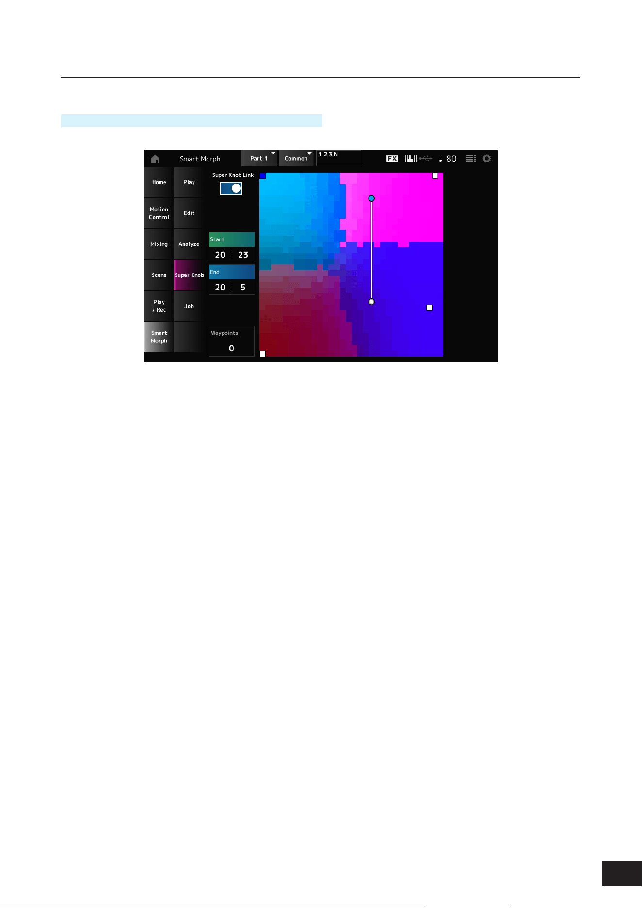
151
MODX M Operation Manual
Super Knob
Operation
[PERFORMANCE (HOME)]
→
Smart Morph
→
Super Knob
Super Knob Link
When set to On, you can use the Super Knob for following the path on the map from start to end, instead of running your
nger across the touchscreen.
Settings: Off, On
Start
Sets the position of the smallest Super Knob value on the map.
When the cursor is on Start, tap on the map to set the value for the starting point.
End
Sets the position of the largest Super Knob value on the map.
When the cursor is on End, tap on the map to set the value of the ending point.
Waypoints
Sets the number of interspersed points (waypoints) between the start and end.
Settings: 0–6
Waypoint 1–Waypoint 6
Sets the position on the map.
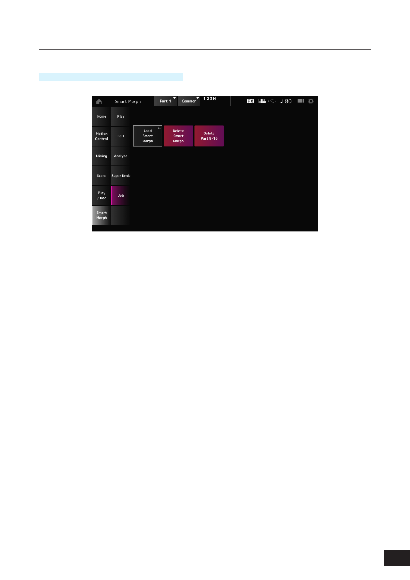
152
MODX M Operation Manual
Job
Operation
[PERFORMANCE (HOME)]
→
Smart Morph
→
Job
Load Smart Morph
Opens the Load screen.
On the Load screen, you can select another Performance and import the Smart Morph settings from that Performance to
the current Performance.
Delete Smart Morph
Deletes the Smart Morph settings from the selected Performance.
Delete Part 9–16
Deletes all Parts 9 to 16 at once to make these Parts unused.
Parts 9 to 16 are used for creating a Smart Morph map.
When you are nished adjusting the parameters and you no longer need to use the map, you can delete Parts 9 to 16.
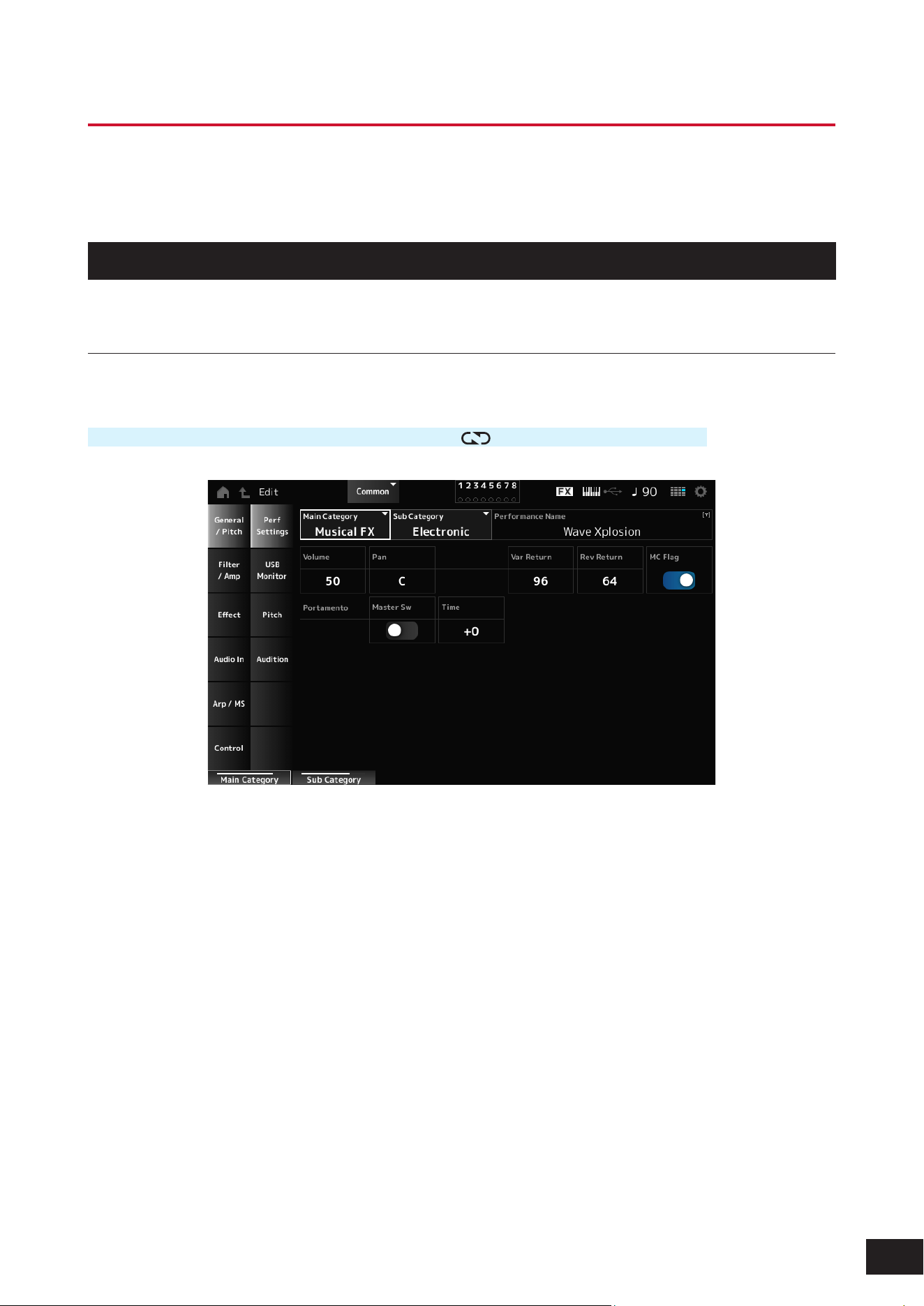
153
MODX M Operation Manual
Common Edit Screens
On the Common Edit screen, you can edit the parameters for the entire Performance as well as the parameters for the
Audio Part.
General/Pitch
Perf Settings
On the Perf Settings screen, you can set general parameters for the Performance.
Operation
[PERFORMANCE (HOME)]
→
Common selection
→
[EDIT/ ]
→
General/Pitch
→
Perf Settings
Main Category
Sub Category
Sets the Main category and Sub category of the selected Performance.
Settings: Refer to the Data List
Performance Name
Names the currently selected Performance. You can use up to 20 alphanumeric characters.
Volume (Performance Volume)
Sets the volume of the selected Performance.
Settings: 0–127
Pan (Performance Pan)
Adjusts the Pan position (stereo position) of the currently selected Performance.
Settings: L63–C (center)–R63

154
MODX M Operation Manual
Var Return (Variation Return)
Sets the output level (Return Level) of the signals processed by the Variation Effect.
Settings: 0–127
Rev Return (Reverb Return)
Sets the output level (Return Level) of the signals processed by the Reverb Effect.
Settings: 0–127
MC Flag (Motion Control Flag)
Sets an MC (Motion Control) ag to the currently selected Performance.
When set to On, the MC ag appears on the Performance screen (HOME), and ltering will be performed by the MC
attribute on the Performance Category Search screen.
Settings: Off, On
Portamento Master Sw (Portamento Master Switch)
Sets Portamento on or off for Parts having the Portamento Part Sw set to On.
This switch is linked to the [PORTAMENTO] button on the top panel.
Settings: Off, On
Portamento Time
Sets the time length (or speed) for the pitch transition of Portamento for the Part.
This is specied as an offset value to the Part Portamento time.
Settings: −64–+0–+63
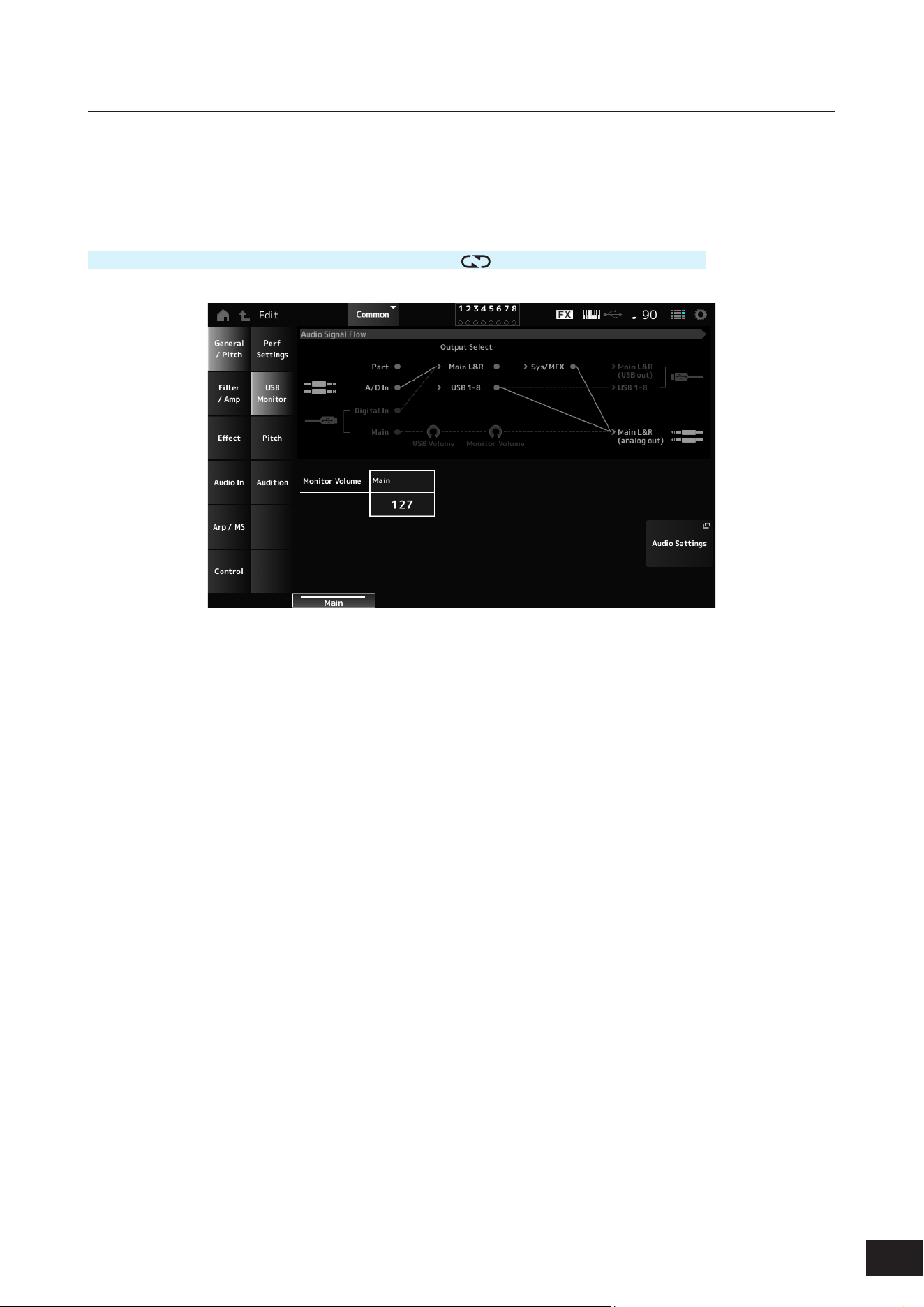
155
MODX M Operation Manual
USB Monitor
Adjusts the volume of the audio signal input from the USB [TO HOST] terminal on the USB Monitor screen.
When you tap on the USB Volume in the Audio Signal Flow, the cursor moves on the Audio I/O screen to the USB Volume.
NOTE
USB Main Monitor Volume is saved (stored) in the Performance.
Operation
[PERFORMANCE (HOME)]
→
Common selection
→
[EDIT/ ]
→
General/Pitch
→
USB Monitor
Monitor Volume Main
Adjusts the volume of the audio signals input from the USB [TO HOST] terminal and output to the OUTPUT jacks.
Settings: 0–127
Audio Settings
Tap to open the Utility Audio I/O screen.
The same screen can be opened from [UTILITY]
→
Settings
→
Audio I/O.
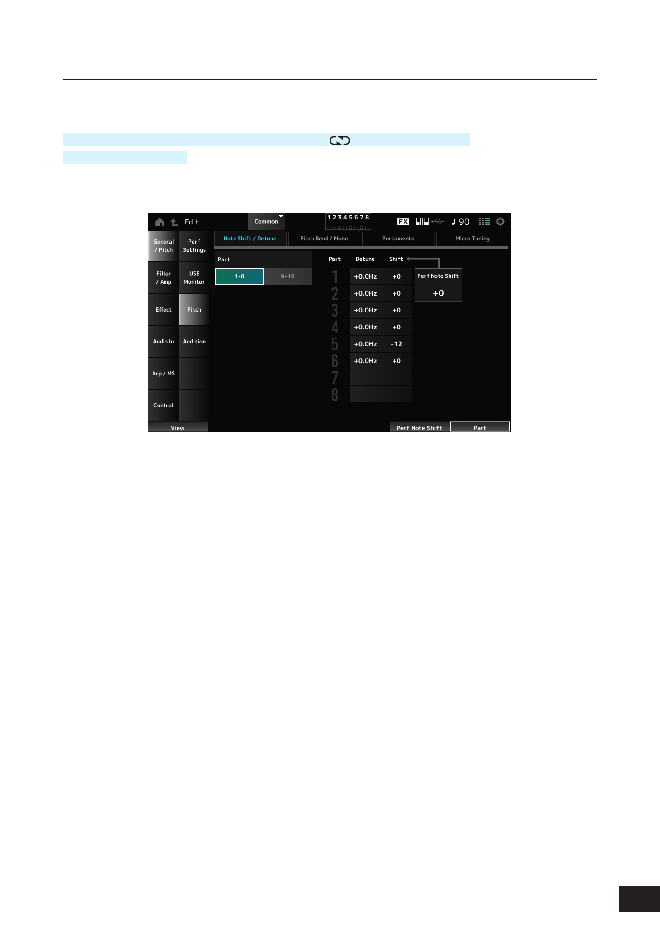
156
MODX M Operation Manual
Pitch
On the Pitch screen, you can make pitch settings.
Operation
[PERFORMANCE (HOME)]
→
Common selection
→
[EDIT/ ]
→
General/Pitch
→
Pitch
[SHIFT] + [PORTAMENTO]
Note Shift / Detune
Part
Switches the view between Part 1-8 and Part 9-16.
Detune
Adjusts the pitch of the Part in 0.1 Hz increments.
By slightly shifting the pitch, you can detune the sound.
Settings: −12.8Hz–+0.0Hz–+12.7Hz
Shift (Note Shift)
Adjusts the pitch of the Part in semitones.
Settings: −24–+0–+24
Perf Note Shift (Performance Note Shift)
Adjusts the pitch of all Parts in semitones.
Settings: −24–+0–+24

157
MODX M Operation Manual
Pitch Bend / Mono
Mono / Poly will not be shown for the Drum Part.
Edit Control Assign
The Common Edit Control Assign screen will open.
Group (Pitch Control Group)
Parts assigned to the same group are given the same pitch.
This is convenient when you wish to apply Portamento to a layered sound or have the same micro-tuning settings for
multiple Parts at once.
Lower (Pitch Bend Lower)
Upper (Pitch Bend Upper)
Sets the range of the changes created with the pitch bend wheel in semitones.
Settings: −48–+0–+24
Mono / Poly
Sets the tone generation mode for the keyboard.
Mono is for playing single notes, and Poly is for playing multiple simultaneous notes.
Settings: Mono, Poly
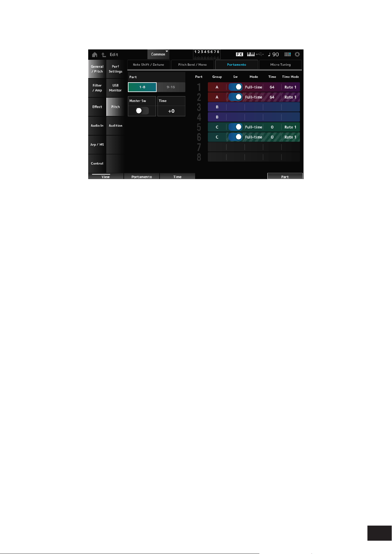
158
MODX M Operation Manual
Portamento
Sw, Mode, Time, and Time Mode will not be shown for the Drum Part.
Master Sw (Portamento Master Switch)
Sets Portamento on or off for Parts having the Sw (Portamento Part Switch) set to On.
This switch is linked to the [PORTAMENTO] button on the top panel.
Settings: Off, On
Time (Portamento Time)
Sets the time length (or speed) for the pitch transition of Portamento for the Part.
This is specied as an offset value to the Part Portamento time.
Settings: −64–+0–+63
Sw (Portamento Part Switch)
Sets Portamento on or off for the Part.
Settings: Off, On
Portamento Mode
Sets the way Portamento is applied according to your keyboard performance.
Settings: Fingered, Full-time
Fingered: Portamento is applied only when you play legato (playing the next note before releasing the previous one)
Full-time: Portamento is applied at all times
Time (Portamento Part Time)
Sets the time length (or speed) for the pitch transition of Portamento for the Part.
Settings: 0–127
Time Mode (Portamento Time Mode)
Sets how the pitch changes over time.
Settings: Rate 1, Time 1, Rate 2, Time 2
Rate 1: Pitch changes at a specic rate.
Time 1: Pitch changes at a specic time.
Rate 2: Pitch changes at a specic rate within an octave.
Time 2: Pitch changes at a specic time within an octave.
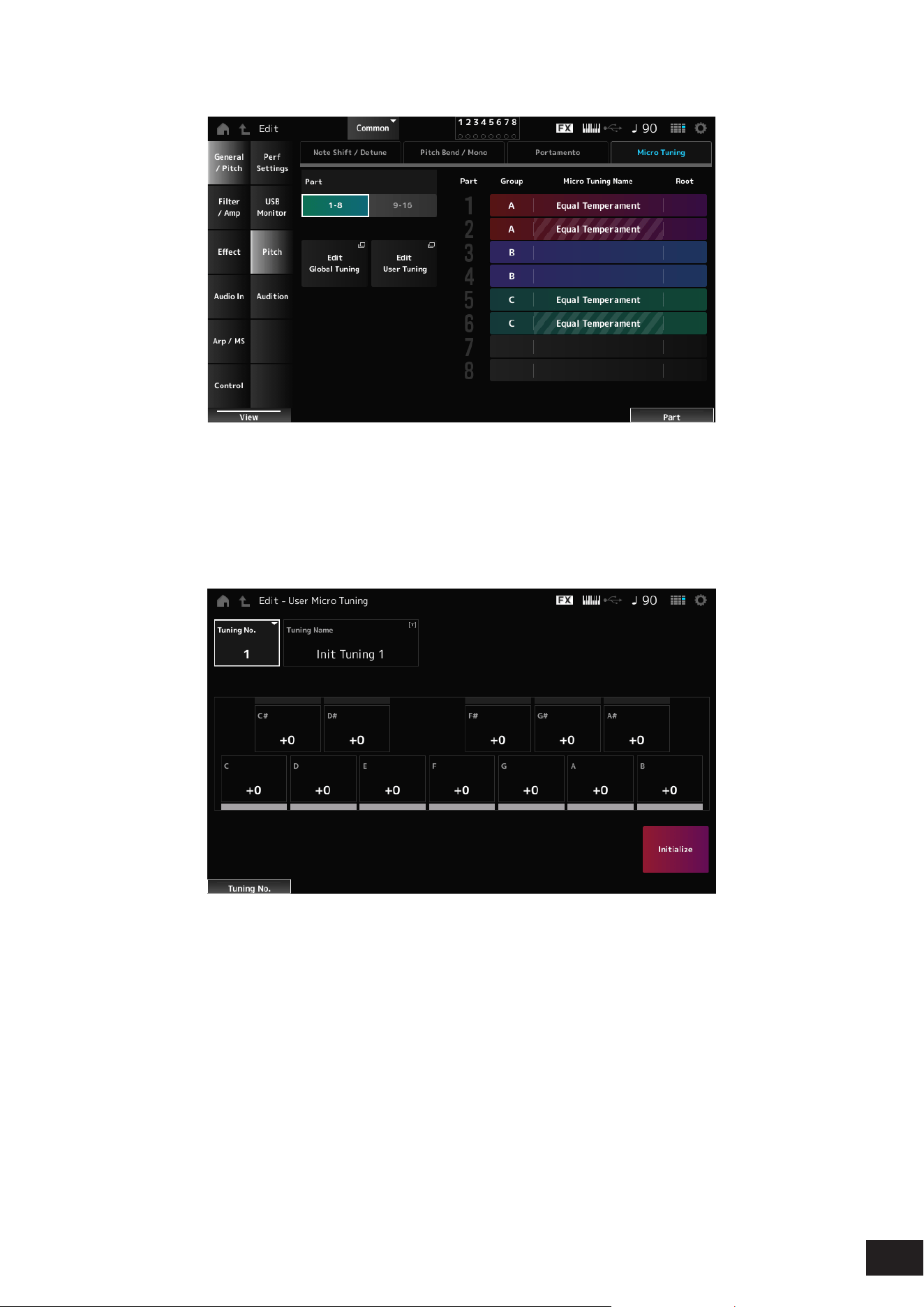
159
MODX M Operation Manual
Micro Tuning
Micro Tuning Name and Root will not be shown for the Drum Part.
Edit Global Tuning
Opens Settings
→
Sound on the Utility screen.
Edit User Tuning
Opens the User Micro Tuning settings window.
• Tuning No. (Micro Tuning Number)
Indicates the selected User Micro Tuning Number.
Settings: 1–8
• Tuning Name (Micro Tuning Name)
You can save the User Micro Tuning you are editing under a new name. You can use up to 20 alphanumeric
characters.
• C, C#, D, D#, E, F, F#, G, G#, A, A#, B
You can adjust the pitch of each note in cent to set the micro tuning.
Settings: −99–+0–+99
• Initialize
Initializes the selected User Micro Tuning.

160
MODX M Operation Manual
Micro Tuning Name
Sets the micro tuning (temperament) for the Part. See the table below for an explanation of each setting.
Settings: Equal Temperament, Pure Major, Pure Minor, Werckmeister, Kirnberger, Vallotti & Young, 1/4 shift, 1/4 tone, 1/8 tone, Indian,
Arabic 1, Arabic 2, Arabic 3
Init Tuning 1–8 (When a user bank is selected)
Library 1–1 – 24–8 (When loading a Library le)
Equal Temperament
Each octave is divided into 12 intervals of equal size. This is the most commonly used tuning in
music.
Pure Major
Pure Minor
These tunings preserve the pure mathematical intervals of each scale, especially for triad
chords (root, third, fth).
You can hear this best in actual vocal harmonies, such as choirs and a cappella singing.
Werckmeister
Kirnberger
Vallotti & Young
Each of the scales combines the mean-tone and Pythagorean scales. The main feature of
these scales is that each key has its unique character.
They were used in the time of Bach and Beethoven, and are used now when playing music from
those eras on instruments like the harpsichord.
1/4 shift
The equal-tempered scale shifted up 50 cents.
You can create tension in your music by mixing this setting with Equal Temperament.
1/4 tone
Twenty-four equally spaced notes per octave.
One octave consists of 24 keys.
1/8 tone
Forty-eight equally spaced notes per octave.
One octave consists of 48 keys.
Indian
Usually observed in Indian music.
Play white keys only.
Arabic
Usually observed in Arabic music.
Root (Micro Tuning Root)
Sets the root note for the micro tuning.
This parameter is not shown when the selected type in Micro Tuning Name does not require a root note.
Settings: C–B
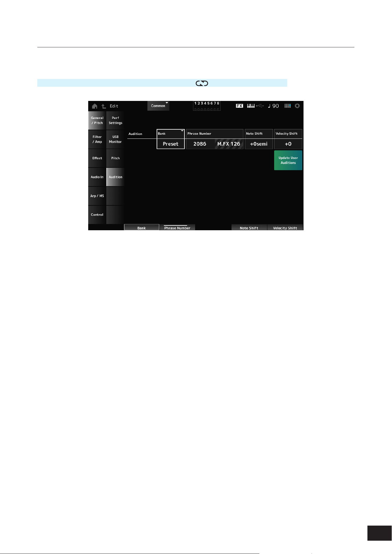
161
MODX M Operation Manual
Audition
On the Audition screen, you can set the audition phrase.
Operation
[PERFORMANCE (HOME)]
→
Common selection
→
[EDIT/
]
→
General/Pitch
→
Audition
Audition Bank
Selects the bank for the audition phrases.
Audition Phrase Number
Selects the audition phrase.
The preset Performances already have suitable audition phrases assigned.
By playing back the audition phrase, you can listen to the selected Performance in an appropriate musical context.
Settings: Refer to the Data List
Note Shift (Audition Note Shift)
Adjusts the pitch of the notes in the audition phrase in semitones.
Settings: −24 semi to +0 semi to +24 semi
Velocity Shift (Audition Velocity Shift)
Adjusts the velocity of the notes in the audition phrase.
Settings: −64–+0–+63
Update User Auditions
Converts all Songs saved to internal memory into User Auditions.
If any User Auditions already exist, all previous User Auditions will be overwritten.
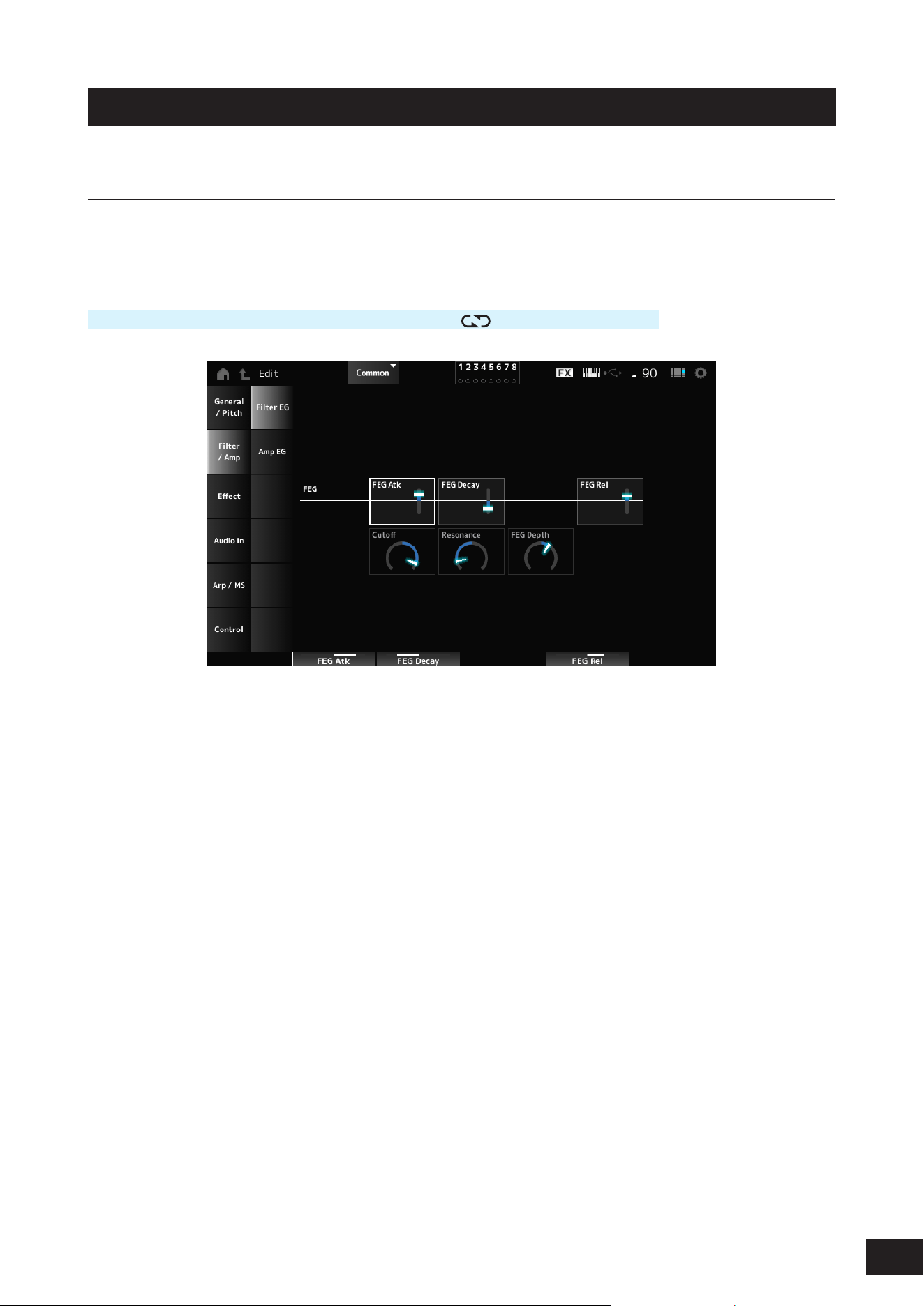
162
MODX M Operation Manual
Filter/Amp
Filter EG
On the Filter EG screen, you can set the Filter Envelope Generator (FEG).
This lets you set the degree (or level) of changes to the cutoff frequency and how those changes evolve over time, starting
from the moment you press a key on the keyboard to the moment the sound decays.
Operation
[PERFORMANCE (HOME)]
→
Common selection
→
[EDIT/ ]
→
Filter/Amp
→
Filter EG
FEG Atk (FEG Attack Time)
Sets the length of time it takes for the sound to change from the moment you press a key to when the Cutoff Frequency
reaches the value set at Attack Level.
This is specied as an offset value to the Part FEG.
Settings: −64–+0–+63
FEG Decay (FEG Decay Time)
Sets the length of time it takes for the Cutoff Frequency to change from the attack level. You can control the crispness or
the decay speed of the sound.
This is specied as an offset value to the Part FEG.
Settings: −64–+0–+63
FEG Rel (FEG Release Time)
Sets the length of time it takes for the Cutoff Frequency to change from the moment you release your nger from the key
until it reaches the Release Level. This allows you to make the decay of the sound after the key is released slower or
faster.
This is specied as an offset value to the Part FEG.
Settings: −64–+0–+63
Cutoff (Cutoff Frequency)
Changes the sound by setting the cutoff frequency of the lter.
When the Low Pass Filter is selected, larger values here result in a brighter sound, and smaller values result in a darker
sound.
This is specied as an offset value to the lter cutoff frequency for the Part.
Settings: −64–+0–+63
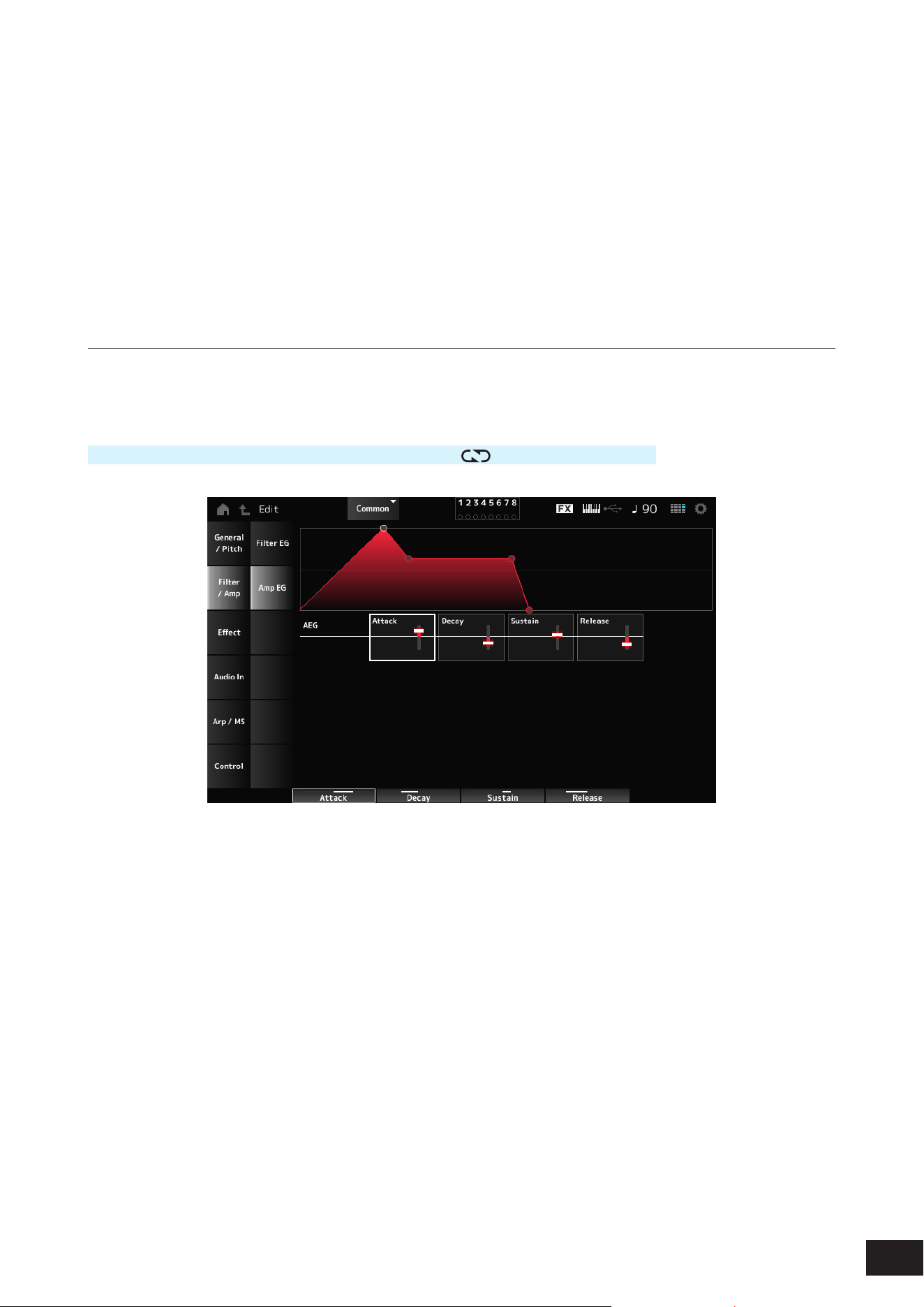
163
MODX M Operation Manual
Resonance
Adds special characteristics to the sound by adjusting the signal level near the cutoff frequency.
This is specied as an offset value to the lter resonance for the Part.
Settings: −64–+0–+63
FEG Depth
Sets the depth range for the cutoff frequency change controlled by the FEG.
This is specied as an offset value to the Part's FEG Depth.
Settings: −64–+0–+63
Amp EG
On the Amp EG screen, you can set the AEG (Amplitude Envelope Generator). By setting the Amp EG, you can set how
the volume changes from the moment you press a key on the keyboard to when the sound decays.
Operation
[PERFORMANCE (HOME)]
→
Common selection
→
[EDIT/ ]
→
Filter/Amp
→
Amp EG
The settings on the Amp EG screen are offset values to the AEG for all Parts.
Attack (AEG Attack Time)
Sets the length of time it takes for the volume to change from the moment you press a key on the keyboard to when it
reaches the maximum.
Settings: −64–+0–+63
Decay (AEG Decay Time)
Sets the length of time it takes for the volume to change after it has reached the maximum.
Settings: −64–+0–+63
Sustain (AEG Sustain Level)
Sets the volume that is maintained while the key is held down.
Settings: −64–+0–+63
Release (AEG Release Time)
Sets the length of time it takes for the sound to decay after you have released the key.
Settings: −64–+0–+63
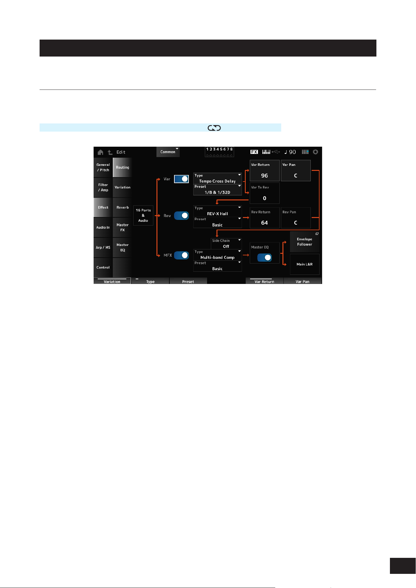
164
MODX M Operation Manual
Effect
Routing
On this screen, you can set the System Effects applied to all Parts and view the signal ow of the Master Effects.
Operation
[PERFORMANCE (HOME)]
→
Common selection
→
[EDIT/
]
→
Effect
→
Routing
Var (Variation Switch)
Rev (Reverb Switch)
MFX (Master Effect Switch)
Sets the Variation Effect, Reverb, and Master Effect on or off.
Settings: Off, On
Var Type (Variation Type)
Rev Type (Reverb Type)
MFX Type (Master Effect Type)
Sets the type for the Variation Effect, Reverb, and Master Effect.
Settings: Refer to the Effect types
Var Preset (Variation Preset Number)
Rev Preset (Reverb Preset Number)
MFX Preset (Master Effect Preset Number)
Selects a Preset from the Variation Effect, Reverb, and Master Effect parameters.
Settings: Refer to the Data List
Side Chain (Variation Side Chain Part)
Side Chain (Master Effect Side Chain Part)
Modulator (Variation Modulator Part)
Modulator (Master Effect Modulator Part)
Sets the Side Chain Part (or the Modulator depending on the effect type) for the Variation Effect and Master Effect.
This parameter is not available when Master is set to the Modulator Part. In that case, the parameter value will be shown
in parenthesis as in "(Master)."
Settings: Part 1–16, A/D, Master, Off
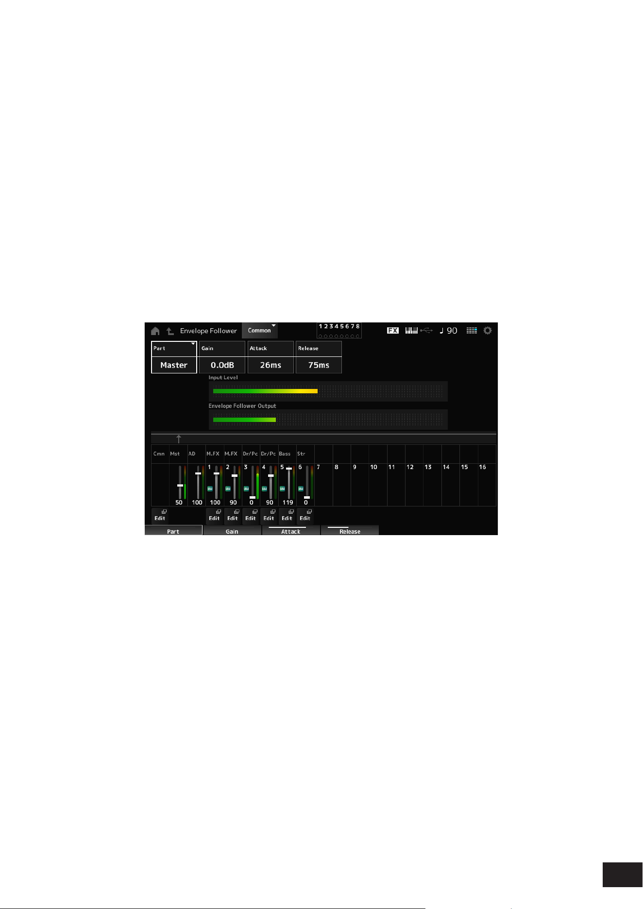
165
MODX M Operation Manual
Var Return (Variation Return)
Rev Return (Reverb Return)
Sets the output level (Return Level) of the signals processed by the Variation Effect or Reverb Effect.
Settings: 0–127
Var to Rev (Variation To Reverb)
Sets the send level of the signals processed by the Variation Effect.
Settings: 0–127
Master EQ (Master EQ Switch)
Sets the Master EQ on or off.
Settings: Off, On
Var Pan (Variation Pan)
Rev Pan (Reverb Pan)
Sets the stereo location of the signals processed by the Variation Effect or the Reverb Effect.
Settings: L63–C (center)–R63
Envelope Follower
Opens the settings screen for the Envelope Follower.
• Part (Input Source)
Shows the input source for the selected Envelope Follower.
Settings: Master, AD, Part 1–16
• Gain (Envelope Follower Gain)
Sets the input gain on the input source set for the Part.
Settings: −24.0dB–0.0dB–+24.0dB
• Attack (Envelope Follower Attack)
Sets the attack time for the envelope follower.
Settings: 1ms–40ms
• Release (Envelope Follower Release)
Sets the release time for the envelope follower.
Settings: 10ms–680ms
• Input Level
Shows the Input level for the signals input from the Input source of the Part you have selected.
• Envelope Follower Output
Shows the output level of the Envelope Follower.
• Edit
Opens the Control Assign screen for the selected Part.
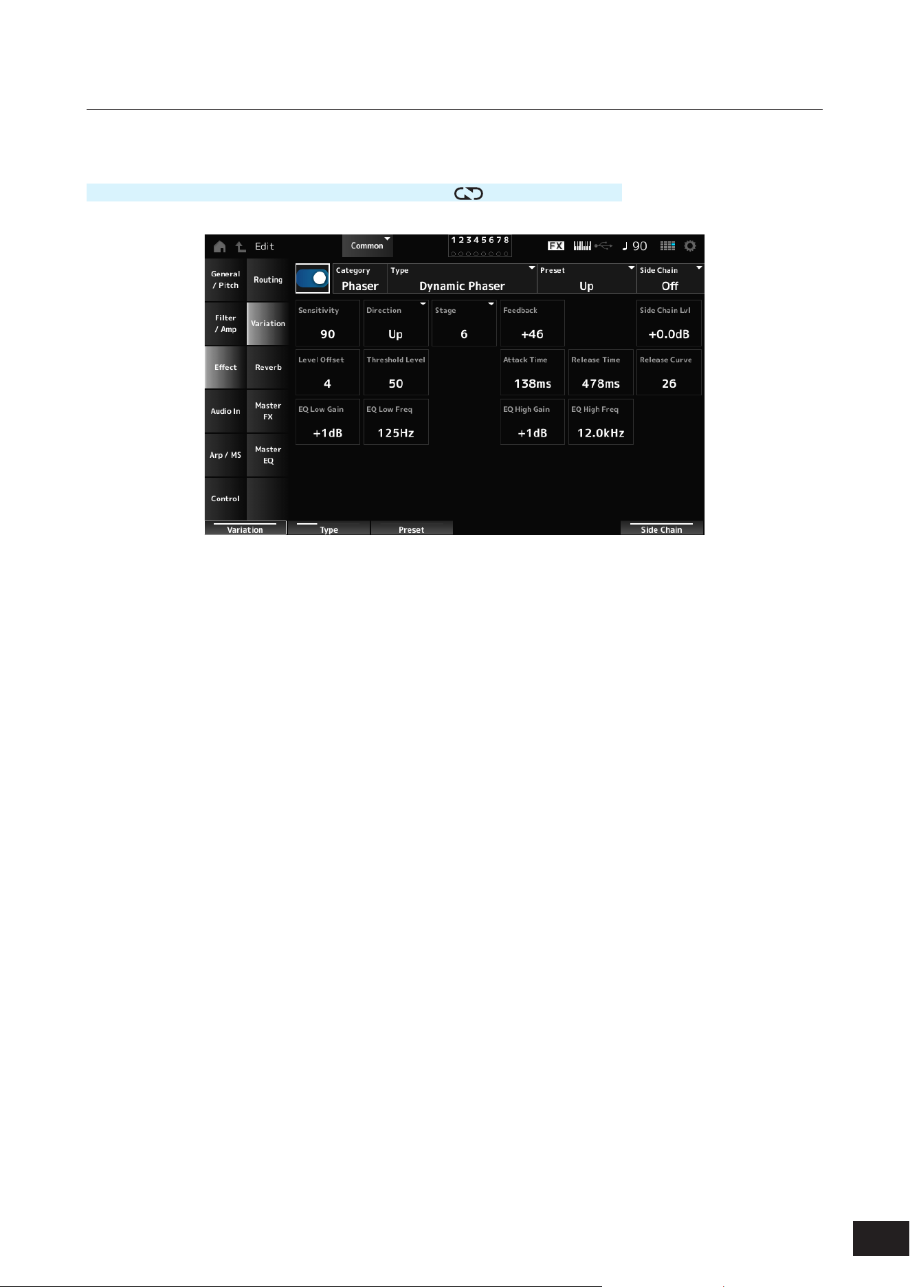
166
MODX M Operation Manual
Variation
Sets the Variation Effect.
Operation
[PERFORMANCE (HOME)]
→
Common selection
→
[EDIT/ ]
→
Effect
→
Variation
Variation Switch
Sets the Variation Effect on or off.
Settings: Off, On
Category (Variation Category)
Type (Variation Type)
Sets the category and type of the Variation Effect.
Settings: Refer to the Effect types
Preset (Variation Preset Number)
Selects one of the Preset effect parameters for each Effect Type.
Settings: Refer to the Data List
Side Chain (Variation Side Chain Part)
Modulator (Variation Modulator Part)
Sets the Part for the Side Chain (or the Modulator depending on the effect type) for the Variation Effect.
This parameter is not available when Master is set to the Modulator Part. In that case, the parameter value will be shown
in parenthesis as in "(Master)."
Settings: Part 1–16, A/D, Master, Off
Effect Parameter
The Effect Parameters differ depending on the effect type.
Settings: Refer to the Effect parameters

167
MODX M Operation Manual
Reverb
Sets the Reverb Effect.
Operation
[PERFORMANCE (HOME)]
→
Common selection
→
[EDIT/ ]
→
Effect
→
Reverb
Reverb Switch
Sets the Reverb Effect on or off.
Settings: Off, On
Category (Reverb Category)
Type (Reverb Type)
Sets the category and type of the Reverb Effect.
Settings: Refer to the Effect types
Preset (Reverb Preset Number)
Selects one of the Preset effect parameters for each Effect Type.
Settings: Refer to the Data List
Effect Parameter
The Effect Parameters differ depending on the effect type.
Settings: Refer to the Effect parameters

168
MODX M Operation Manual
Master FX
Sets the Master Effect.
Operation
[PERFORMANCE (HOME)]
→
Common selection
→
[EDIT/ ]
→
Effect
→
Master FX
Master Effect Switch
Sets the Master Effect on or off.
Settings: Off, On
Category (Master Effect Category)
Type (Master Effect Type)
Sets the category and type of the Master Effect.
Settings: Refer to the Effect parameters
Preset (Master Effect Preset Number)
Selects one of the Preset effect parameters for each Effect Type.
Settings: Refer to the Data List
Side Chain (Master Effect Side Chain Part)
Modulator (Master Effect Modulator Part)
Sets the Side Chain (or the Modulator depending on the effect type) for the Master Effects.
This parameter is not available when Master is set to the Modulator Part. In that case, the parameter value will be shown
in parenthesis as in "(Master)."
Settings: Part 1–16, A/D, Master, Off
Effect Parameter
The Effect Parameters differ depending on the effect type.
Settings: Refer to the Effect parameters
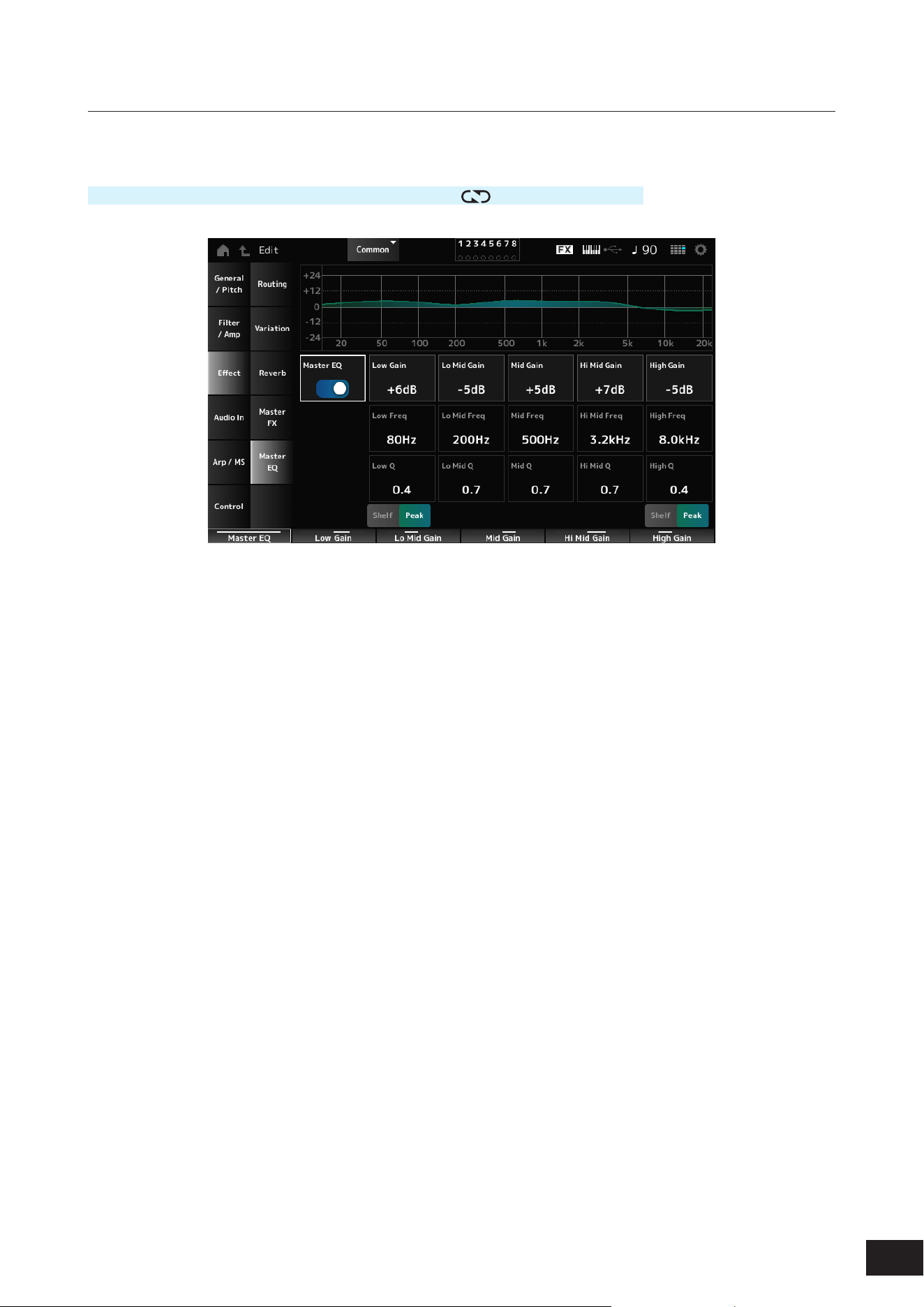
169
MODX M Operation Manual
Master EQ
Sets the Master EQ.
Operation
[PERFORMANCE (HOME)]
→
Common selection
→
[EDIT/ ]
→
Effect
→
Master EQ
Master EQ (Master EQ Switch)
Sets the Master EQ on or off.
Settings: Off, On
Low Gain (Master EQ Low Gain)
Sets the signal level of the Low band.
Settings: −12dB – +0dB – +12dB
Lo Mid Gain (Master EQ Low Mid Gain)
Sets the signal level of the Lo Mid band.
Settings: −12dB – +0dB – +12dB
Mid Gain (Master EQ Mid Gain)
Sets the signal level of the Mid band.
Settings: −12dB – +0dB – +12dB
Hi Mid Gain (Master EQ High Mid Gain)
Sets the signal level of the Hi Mid band.
Settings: −12dB – +0dB – +12dB
High Gain (Master EQ High Gain)
Sets the signal level of the High band.
Settings: −12dB – +0dB – +12dB
Low Freq (Master EQ Low Frequency)
Sets the frequency of the Low band.
Settings: 32Hz – 2.0kHz

170
MODX M Operation Manual
Lo Mid Freq (Master EQ Low Mid Frequency)
Sets the frequency of the Lo Mid band.
Settings: 100Hz – 10kHz
Mid Freq (Master EQ Mid Frequency)
Sets the frequency of the Mid band.
Settings: 100Hz – 10kHz
Hi Mid Freq (Master EQ High Mid Frequency)
Sets the frequency of the Hi Mid band.
Settings: 100Hz – 10kHz
High Freq (Master EQ High Frequency)
Sets the frequency of the High band.
Settings: 500Hz – 16kHz
Low Q (Master EQ Low Q)
Sets the bandwidth of the Low band.
This parameter is available only when Low Shape (Master EQ Low Shape) is set to Peak.
Settings: 0.1–12.0
Lo Mid Q (Master EQ Low Mid Q)
Sets the bandwidth of the Lo Mid band.
Settings: 0.1–12.0
Mid Q (Master EQ Mid Q)
Sets the bandwidth of the Mid band.
Settings: 0.1–12.0
Hi Mid Q (Master EQ High Mid Q)
Sets the bandwidth of the Hi Mid band.
Settings: 0.1–12.0
High Q (Master EQ High Q)
Sets the bandwidth of the High band.
This parameter is available only when High Shape (Master EQ High Shape) is set to Peak.
Settings: 0.1–12.0
Low Shape (Master EQ Low Shape)
High Shape (Master EQ High Shape)
Sets whether to use Low and High as shelving type (a type that boosts or cuts signals below or above a specic
frequency) or peaking type (a type that boosts or cuts signals in a specic frequency band).
Settings: Shelf, Peak
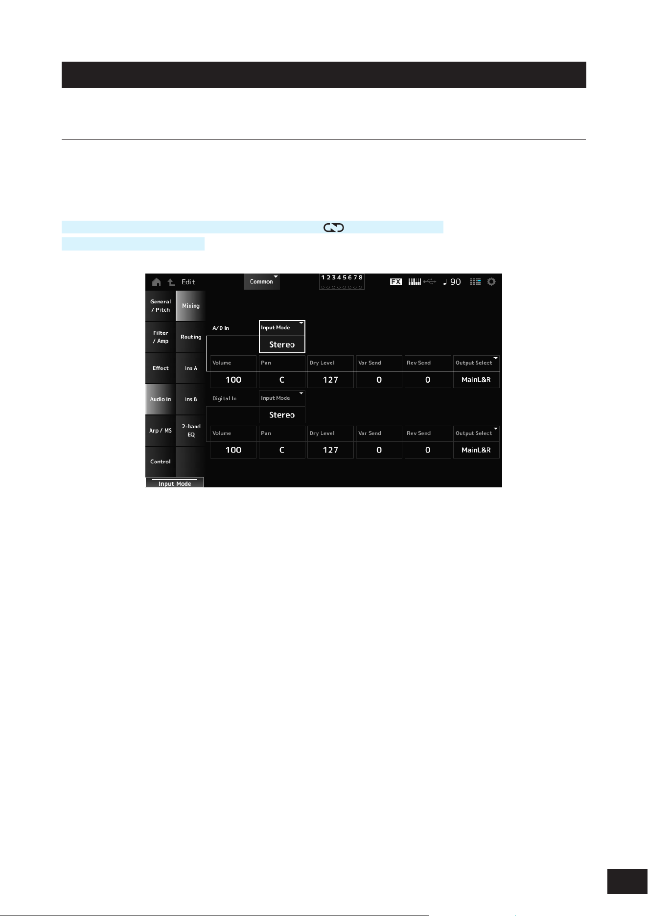
171
MODX M Operation Manual
Audio In
Mixing
On the Mixing screen, you can mix the A/D Part (signals from the A/D INPUT jacks) and the Digital Part (signals from the
USB [TO HOST] terminal).
*The signal from the USB [TO HOST] terminal is the audio set to Digital L/R in the device port.
Operation
[PERFORMANCE (HOME)]
→
Common selection
→
[EDIT/ ]
→
Audio In
→
Mixing
[SHIFT] + [A/D INPUT ON/OFF]
Input Mode (A/D Part Input Mode)
Input Mode (Digital Part Input Mode)
Determines the processing method for the input signals at the left and right channels.
Settings: L Mono, R Mono, L+R Mono, Stereo
L Mono: Uses only the left channel.
R Mono: Uses only the right channel.
L+R Mono: Mixes the left and right channels and processes in mono.
Stereo: Processes the stereo input in stereo.
NOTE
If the sound is input only from the [L/MONO] jack, it is processed in mono.
Volume (A/D Part Volume)
Volume (Digital Part Volume)
Sets the volume of the A/D Part or Digital Part.
Settings: 0–127
Pan (A/D Part Pan)
Pan (Digital Part Pan)
Sets the Pan position (in the stereo eld) for the A/D Part or Digital Part.
Settings: L63–C (center)–R63

172
MODX M Operation Manual
Dry Level (A/D Part Dry Level)
Dry Level (Digital Part Dry Level)
Sets the dry level (or the level of the signals not processed by the System Effect) of the A/D Part or Digital Part.
This parameter is available only when Output Select is set to MainL&R.
Settings: 0–127
Var Send (A/D Part Variation Send)
Var Send (Digital Part Variation Send)
Sets the level of the signals sent from the A/D Part or Digital Part to the Variation Effect.
This parameter is available only when Output Select is set to MainL&R.
Settings: 0–127
Rev Send (A/D Part Reverb Send)
Rev Send (Digital Part Reverb Send)
Sets the level of the signals sent from the A/D Part or Digital Part to the Reverb Effect.
This parameter is available only when Output Select is set to MainL&R.
Settings: 0–127
Output Select (A/D Part Output Select)
Output Select (Digital Part Output Select)
Sets the output destination for the audio signals from the A/D Part or Digital Part.
Settings: MainL&R, (AsgnL&R), USB Stereo, (AsgnL), (AsgnR), USB mono, Off
MainL&R: Outputs in stereo (two channels) to the OUTPUT [L/MONO] and OUTPUT [R] jacks.
USB Stereo: Outputs in stereo (channels 1 and 2, to channels 7 and 8) to the USB [TO HOST] terminal
USB mono: Outputs in mono (channels 1 to 8) to the USB [TO HOST] terminal
Off: No output of the audio signal for the Part.
NOTE
The settings for data compatibility with MONTAGE M are shown below. They are considered Off when set.
• AsgnL&R
• USB Stereo: USB9&10 – USB29&30
• USB mono: USB9 – USB30
• AsgnL
• AsgnR
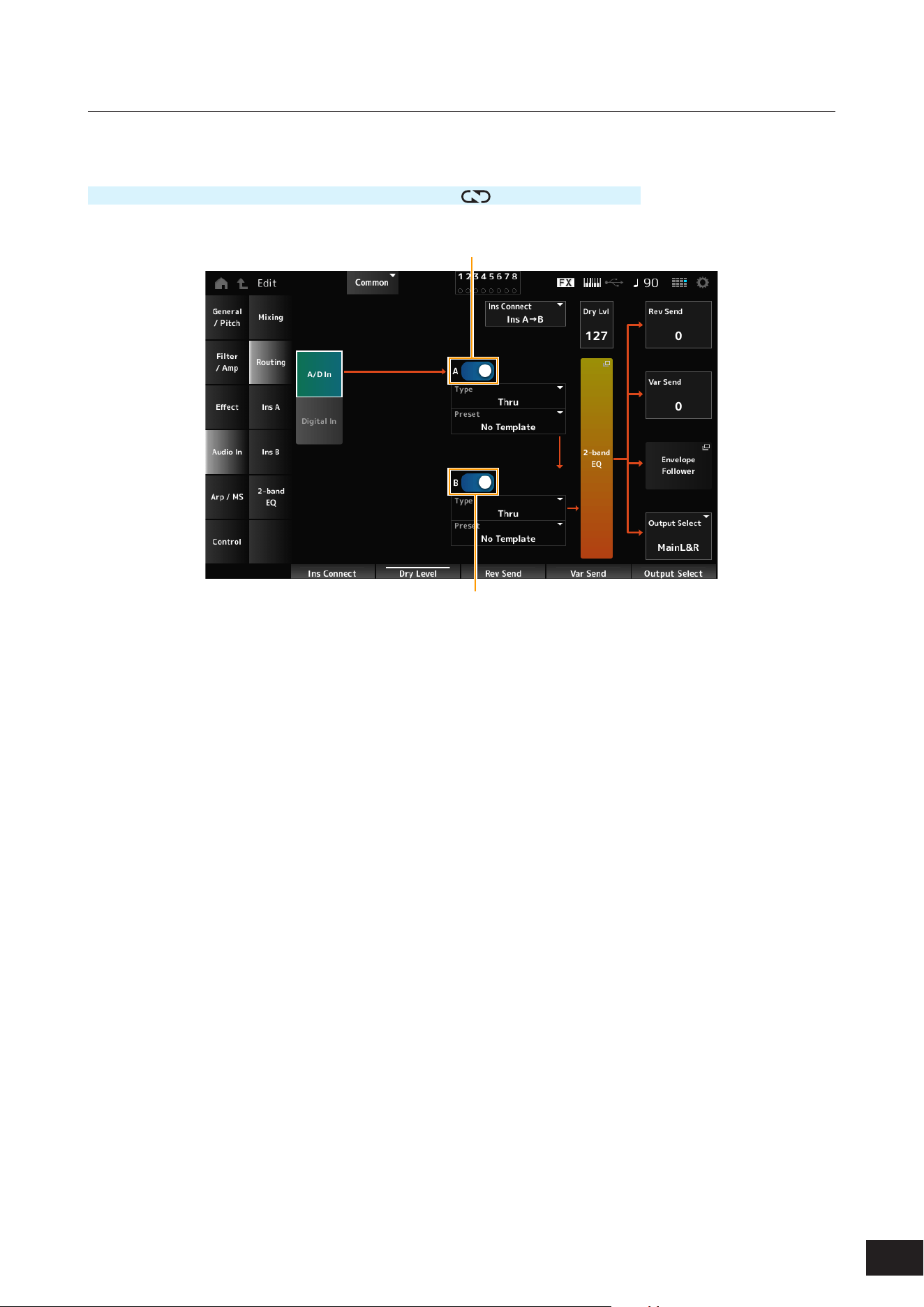
173
MODX M Operation Manual
Routing
On the Routing screen, you can set the effect routing of the A/D Part.
Operation
[PERFORMANCE (HOME)]
→
Common selection
→
[EDIT/ ]
→
Audio In
→
Routing
(1)
(2)
(1) A/D Part Insertion FX A Switch
(2) A/D Part Insertion FX B Switch
A/D In
Digital In
Switches the view between A/D In and Digital In.
When Digital In is selected, only the Digital Part Reverb Send, Digital Part Variation Send, and Digital Part Output Select
are available.
A/D Part Insertion FX A Switch
A/D Part Insertion FX B Switch
Turns Insertion Effect A and Insertion Effect B on or off.
Settings: Off, On
Type (A/D Part Insertion Effect A Type)
Type (A/D Part Insertion Effect B Type)
Sets the Effect Type.
Settings: Refer to the Effect types
Preset (A/D Part Insertion Effect A Preset)
Preset (A/D Part Insertion Effect B Preset)
Selects one of the Preset effect parameters for each Effect Type.
By selecting a Preset, you can change the way effects are applied.
Settings: Refer to the Data List

174
MODX M Operation Manual
Side Chain (A/D Part Insertion Effect A Side Chain)
Side Chain (A/D Part Insertion Effect B Side Chain)
Modulator (A/D Part Insertion Effect A Modulator)
Modulator (A/D Part Insertion Effect B Modulator)
Sets the Side Chain Part (or the Modulator depending on the effect type) for the Insertion Effect A or Insertion Effect B.
This parameter is not available when the Part itself or Master is set to the Modulator. In that case, the parameter value will
be shown in parenthesis as in "(Master)."
Settings: Part 1–16, A/D, Master, Off
Ins Connect (A/D Part Insertion Effect Connect Type)
Sets the effect routing for Insertion Effect A and Insertion Effect B. The diagram changes accordingly when the settings
are changed.
Settings: Ins A
→
B, Ins B
→
A
Dry Level (A/D Part Dry Level)
Sets the dry level (or the level of the signals not processed by the System Effect) of the AD Part.
This parameter is available only when Output Select is set to MainL&R.
Settings: 0–127
2-band EQ
Opens the 2-band EQ 2-band EQ screen for the A/D Part.
Rev Send (A/D Part Reverb Send)
Rev Send (Digital Part Reverb Send)
Sets the level of the signals (or bypass signals) sent from Insertion Effect A or Insertion Effect B to the Reverb Effect.
This parameter is available only when Output Select is set to MainL&R.
Settings: 0–127
Var Send (A/D Part Variation Send)
Var Send (Digital Part Variation Send)
Sets the level of the signals (or bypass signals) sent from Insertion Effect A or Insertion Effect B to the Variation Effect.
This parameter is available only when Output Select is set to MainL&R.
Settings: 0–127
Envelope Follower
Opens the settings screen for Envelope Follower.
Output Select (A/D Part Output Select)
Output Select (Digital Part Output Select)
Sets the output destination for the audio signals.
Settings: MainL&R, (AsgnL&R), USB Stereo, (AsgnL), (AsgnR), USB mono, Off
MainL&R: Outputs in stereo (two channels) to the OUTPUT [L/MONO] and OUTPUT [R] jacks.
USB Stereo: Outputs in stereo (channels 1 and 2, to channels 7 and 8) to the USB [TO HOST] terminal
USB mono: Outputs in mono (channels 1 to 8) to the USB [TO HOST] terminal
Off: No output of the audio signal for the Part.
NOTE
The settings for data compatibility with MONTAGE M are shown below. They are considered Off when set.
• AsgnL&R
• USB Stereo: USB9&10 – USB29&30
• USB mono: USB9 – USB30
• AsgnL
• AsgnR
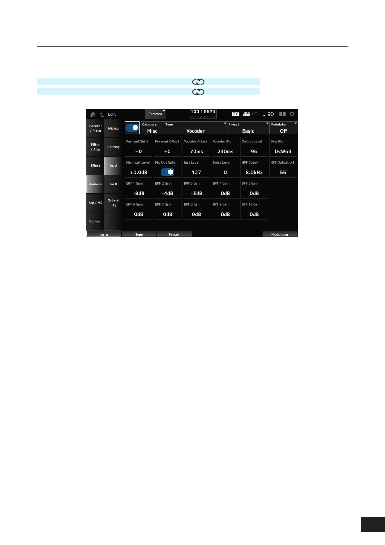
175
MODX M Operation Manual
Ins A, Ins B
On the Ins A and Ins B screens, you can set the Insertion Effects.
Operation
[PERFORMANCE (HOME)]
→
Common selection
→
[EDIT/ ]
→
Audio In
→
Ins A
[PERFORMANCE (HOME)]
→
Common selection
→
[EDIT/
]
→
Audio In
→
Ins B
Insertion FX Switch
Enables the Insertion Effect.
Settings: Off, On
Category (Insertion Effect A Category)
Category (Insertion Effect B Category)
Type (Insertion Effect A Type)
Type (Insertion Effect B Type)
Sets the category and type of the Insertion Effect.
Settings: Refer to the Effect types
Preset (Insertion Effect A Preset)
Preset (Insertion Effect B Preset)
Selects one of the Preset effect parameters for each Effect Type. By selecting a Preset, you can change the way effects
are applied.
Settings: Refer to the Data List
Side Chain (Insertion Effect A Side Chain Part)
Side Chain (Insertion Effect B Side Chain Part)
Modulator (Insertion Effect A Modulator Part)
Modulator (Insertion Effect B Modulator Part)
Sets the Side Chain Part (or the Modulator depending on the effect type) for the Insertion Effect A or Insertion Effect B.
This parameter is not available when the Part itself or Master is set to the Modulator. In that case, the parameter value will
be shown in parenthesis as in "(Master)."
Settings: Part 1–16, A/D, Master, Off
Effect Parameter
The Effect Parameters differ depending on the effect type.
Settings: Refer to the Effect parameters
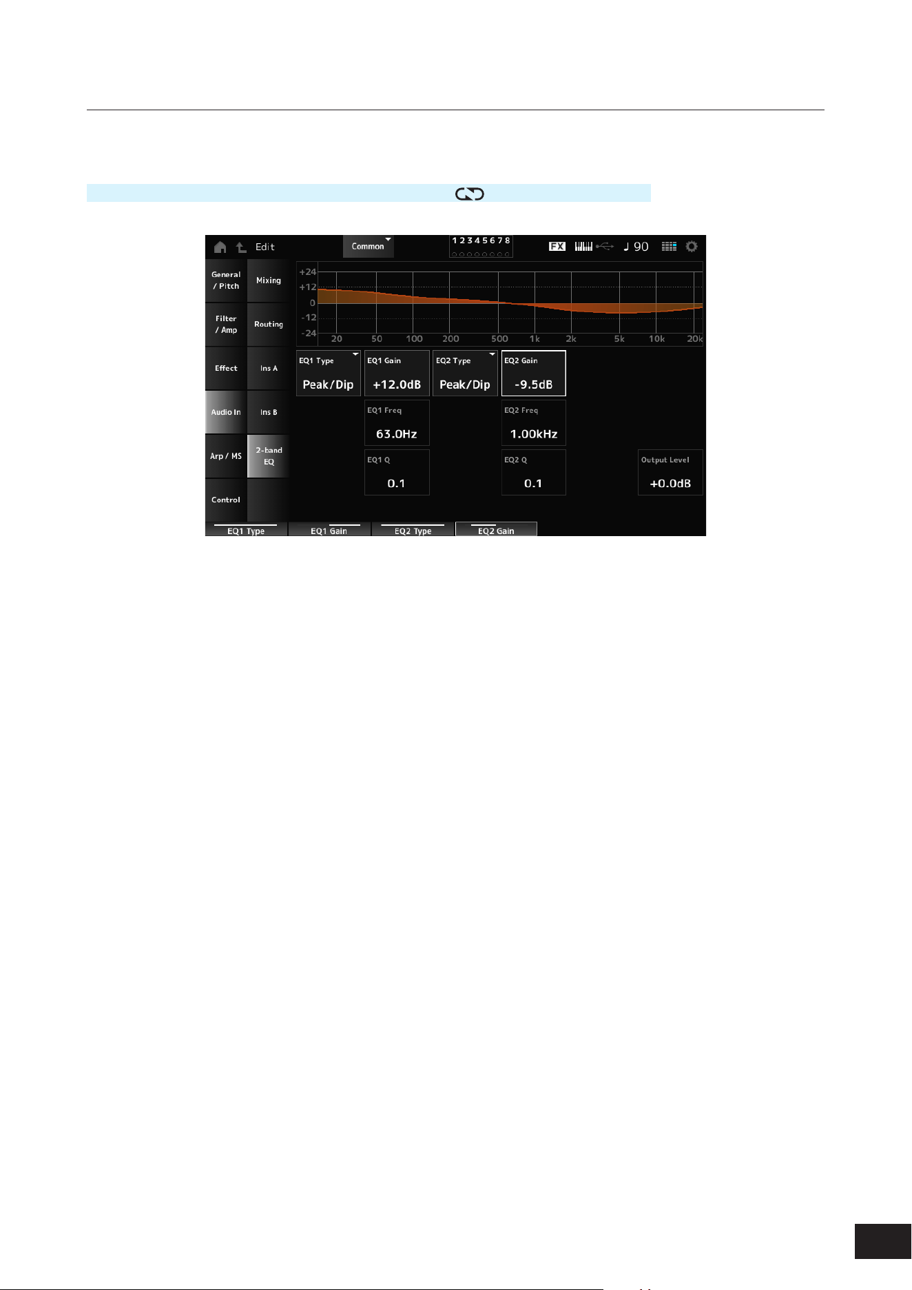
176
MODX M Operation Manual
2-band EQ
On the 2-band EQ screen, you can set the Part EQ.
Operation
[PERFORMANCE (HOME)]
→
Common selection
→
[EDIT/ ]
→
Audio In
→
2-band EQ
EQ1 Type (A/D Part 2-band EQ 1 Type)
EQ2 Type (A/D Part 2-band EQ 2 Type)
Selects the desired EQ type.
Settings: Thru, LPF, HPF, Low Shelf, Hi Shelf, Peak/Dip
Thru: Passes the signals with no effects being applied.
LPF: Cuts the signals above the cutoff frequency.
HPF: Cuts the signals below the cutoff frequency.
Low Shelf: Cuts or boosts the signals below the specied frequency setting.
Hi Shelf: Cuts or boosts the signals above the specied frequency setting.
Peak/Dip: Cuts or boosts the signals at the specied frequency setting.
EQ 1 Freq (A/D Part 2-band EQ 1 Frequency)
EQ 2 Freq (A/D Part 2-band EQ 2 Frequency)
Sets the frequency to be cut or boosted.
This parameter is not available when the EQ Type is set to Thru.
Settings: 63.0Hz–18.0kHz
EQ 1 Gain (A/D Part 2-band EQ 1 Gain)
EQ 2 Gain (A/D Part 2-band EQ 2 Gain)
Sets the signal level of the frequency band set in EQ1 Freq or EQ2 Freq.
This parameter is not available when the EQ Type is set to Thru, LPF, or HPF.
Settings: −12.0dB – +0.0dB – +12.0dB
EQ 1 Q (A/D Part 2-band EQ 1 Q)
EQ 2 Q (A/D Part 2-band EQ 2 Q)
Sets the bandwidth for cutting or boosting the volume of the frequencies set with EQ1 Freq or EQ2 Freq.
This parameter is available only when the EQ Type is set to Peak/Dip.
Settings: 0.1–12.0
Output Level (A/D Part 2-band EQ Output Level)
Sets the output gain of the 2-band EQ.
Settings: −12.0dB – +0.0dB – +12.0dB
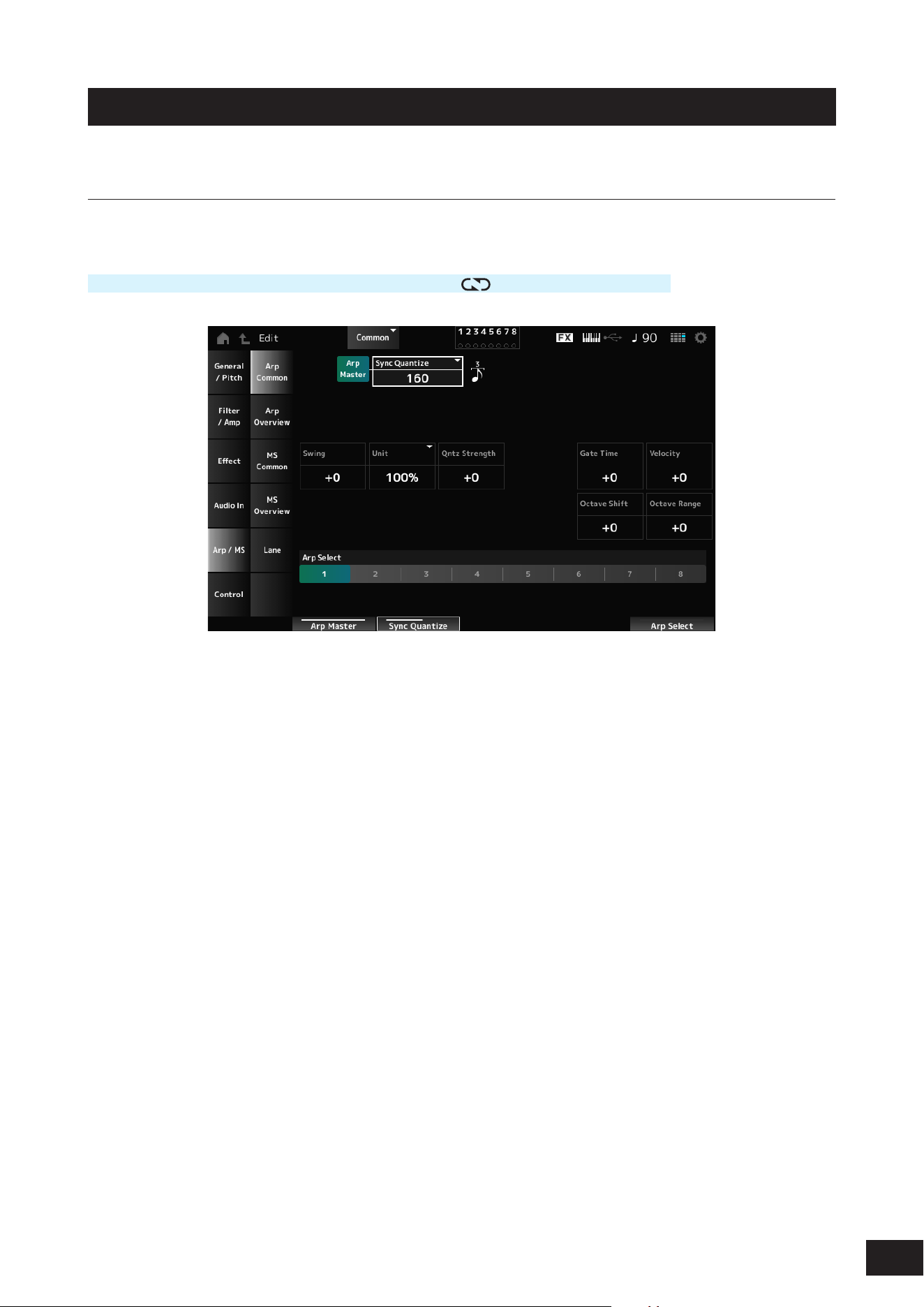
177
MODX M Operation Manual
Arp/MS
Arp Common
On the Arp Common screen, you can set the Arpeggio parameters for the entire Performance.
Operation
[PERFORMANCE (HOME)]
→
Common selection
→
[EDIT/ ]
→
Arp/MS
→
Arp Common
Arp Master (Arpeggio Master Switch)
Sets the Arpeggio for the Performance on or off. This switch is linked to the [ARP] buttons on the top panel.
Settings: Off, On
Sync Quantize (Arpeggio Sync Quantize Value)
Adjusts the timing for starting the next Arpeggio phrase while the rst Arpeggio is being played back, when playing back
Arpeggio phrases in multiple Parts. When set to Off, the Arpeggio is played back when the Part is played on the keyboard.
Settings: Off, 60 (thirty-second note), 80 (sixteenth note triplet), 120 (sixteenth note), 160 (eighth note triplet), 240 (eighth note), 320
(quarter note triplet), 480 (quarter note) (Numbers indicated here are clock values)
Swing (Swing Offset)
Sets the swing value of the Arpeggio and Motion Sequencer for the Performance.
This is specied as an offset value to Part Swing.
Settings: −120 –+ 0 –+120
Unit (Common Unit Multiply)
Sets the percentage for stretching or compressing the Arpeggio playback time for the entire Performance.
This parameter affects Parts for which Part Unit (Arpeggio Unit Multiply) is set to Common.
The subdivision of the beat and the tempo will change when you stretch or compress the playback time, so you can create
a completely new feel for the originally selected Arpeggio.
Settings: 50%, 66%, 75%, 100%, 133%, 150%, 200%, 266%, 300%, 400%
200%: The playback time is doubled, and the tempo is halved
100%: The playback time is kept unchanged
50%: The playback time is halved, and the tempo is doubled

178
MODX M Operation Manual
Qntz Strength (Arpeggio Quantize Strength Offset)
Sets the strength of the quantize setting that is applied to the Arpeggio for the Performance.
This is specied as an offset value to the Qntz Strength (Arpeggio Quantize Strength) of each Part.
Settings: −100–+0–+100
Gate Time (Arpeggio Gate Time Rate Offset)
Sets the Arpeggio Gate Time Rate for the Performance.
This is specied as an offset value to the Gate Time (Arpeggio Gate Time Rate) of each Part.
Settings: −100–+0–+100
Velocity (Arpeggio Velocity Rate Offset)
Sets the Arpeggio Velocity Rate for the Performance.
This is specied as an offset value to the Velocity (Arpeggio Velocity Rate) of each Part.
Settings: −100–+0–+100
Octave Shift (Arpeggio Octave Shift Offset)
Shifts the pitch of the Arpeggio for the Performance in octaves.
This is specied as an offset value to the Octave Shift (Arpeggio Octave Shift) of each Part.
Settings: −20–+0–+20
Octave Range (Arpeggio Octave Range Offset)
Shifts the range of the Arpeggio for the Performance in octaves.
This is specied as an offset value to the Octave Range (Arpeggio Octave Range) of each Part.
Settings: −6–+0–+6
Arp Select (Arpeggio Select)
Selects the Arpeggio.
Settings: 1–8
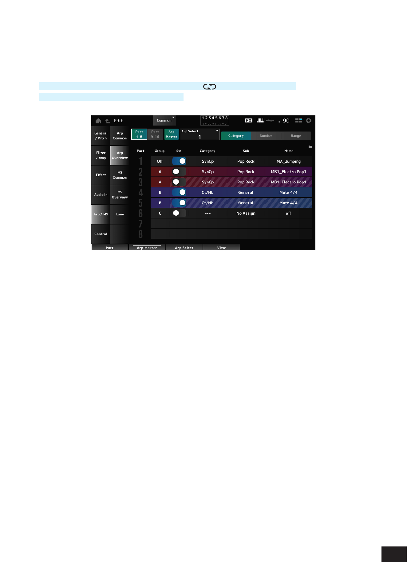
179
MODX M Operation Manual
Arp Overview (Arpeggio Overview)
On the Arp Overview screen, you can set the Arpeggio types from the list of all Parts.
Operation
[PERFORMANCE (HOME)]
→
Common selection
→
[EDIT/ ]
→
Arp/MS
→
Arp Overview
(When a selected Part is Common) [SHIFT] + [ARP]
Part 1–8
Part 9–16
Switches the view for Parts.
Settings: Part 1–8, Part 9–16
Arp Master (Arpeggio Master Switch)
Sets the Arpeggio for the Performance on or off.
This switch is linked to the [ARP] buttons on the top panel.
Settings: Off, On
Group (Arpeggio Group)
Sets the Arpeggio Group for using the same Arpeggio on multiple Parts. The Parts set in the same Group will have the
same Arpeggio settings.
Arp Select (Arpeggio Select)
Selects the Arpeggio.
Settings: 1–8
Sw (Part Arpeggio Switch)
Sets the Arpeggio of each Part on or off.
Settings: Off, On

180
MODX M Operation Manual
When View is set to Category
Category (Arpeggio Category)
Sub (Arpeggio Sub Category)
Name (Arpeggio Name)
Settings: Refer to the Data List
When View is set to Number
Bank (Arpeggio Bank)
Number (Arpeggio Number)
Name (Arpeggio Name)
Settings: Refer to the Data List
When View is set to Range
Name (Arpeggio Name)
Settings: Refer to the Data List
Velocity Limit (Arpeggio Velocity Limit)
Sets the velocity range (lowest and highest values) for Arpeggio playback.
When this is set so that the higher value is rst and the lower value is second (for example, 93 to 34), the Arpeggio is
played only for velocities of 1 to 34 and 93 to 127.
Settings: 1–127
Note Limit (Arpeggio Note Limit)
Sets the note range (the lowest and the highest notes) for Arpeggio playback.
When the rst note specied is higher than the second (for example, C5 to C4), the notes in the ranges C−2 to C4 and C5
to G8 will be played.
Settings: C−2–G8
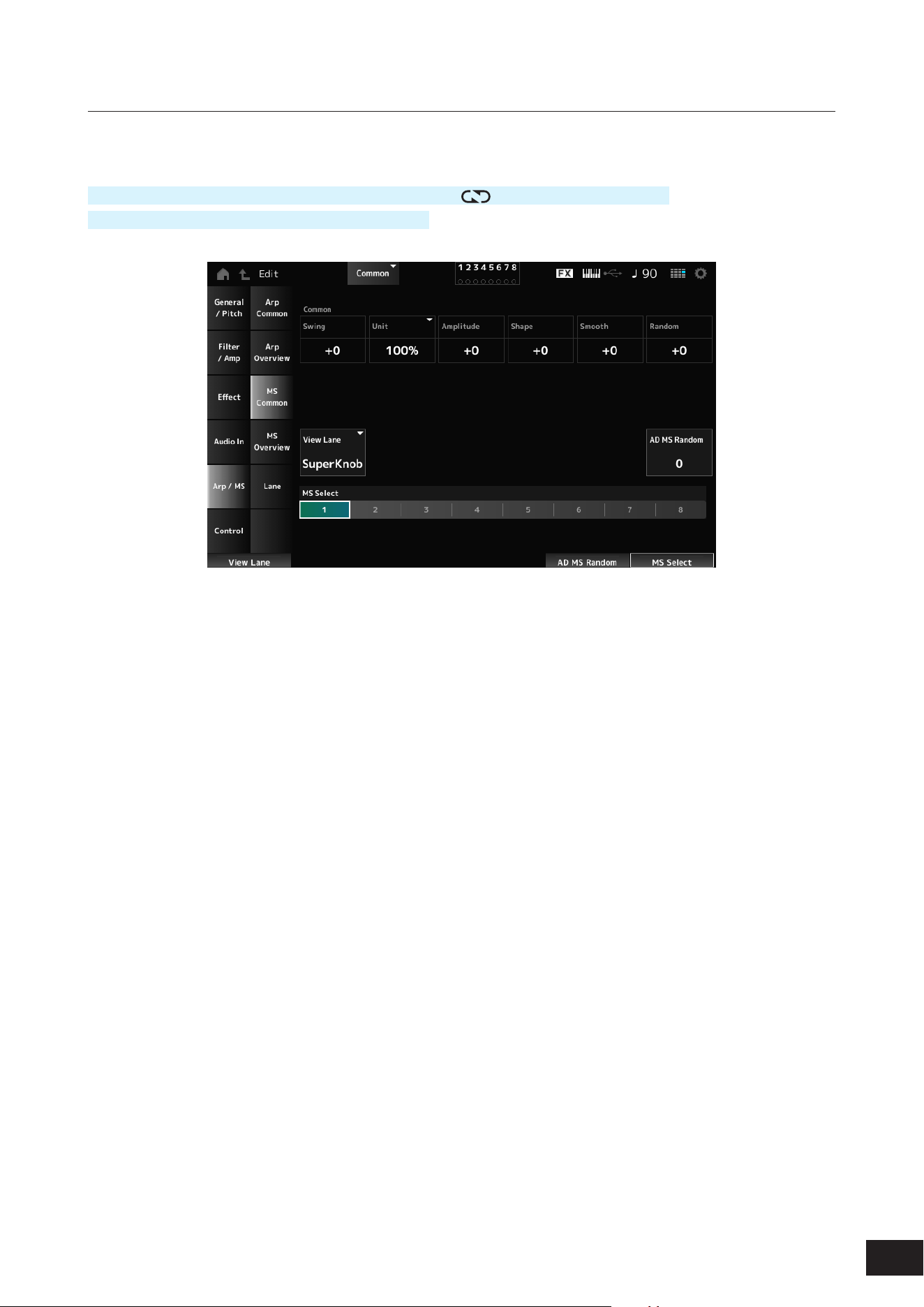
181
MODX M Operation Manual
MS Common (Motion Sequencer Common)
On the MS Common screen, you can set the Motion Sequencer parameters used for the entire Performance.
Operation
[PERFORMANCE (HOME)]
→
Common selection
→
[EDIT/ ]
→
Arp/MS
→
MS Common
(When a selected Part is Common) [SHIFT] + [MSEQ]
Common Swing (Swing Offset)
Sets the swing value of the Arpeggio and Motion Sequencer for the Performance.
This is specied as an offset value to the Part Swing.
Settings: −120 –+0–+120
Common Unit (Common Unit Multiply)
Sets the percentage for stretching or compressing the Motion Sequencer playback time for the entire Performance.
This parameter affects Lanes for which Unit is set to Common.
The subdivision of the beat and the tempo will change when you stretch or compress playback time, so you can create a
completely new feel for the Motion Sequence you have originally selected.
Settings: 50%, 66%, 75%, 100%, 133%, 150%, 200%, 266%, 300%, 400%
200%: The playback time is doubled, and the tempo is halved
100%: The playback time is kept unchanged
50%: The playback time is halved, and the tempo is doubled
Common Amplitude (Motion Sequencer Amplitude Performance Offset)
Sets the Motion Sequencer Amplitude (or how much the Sequence changes) for the entire Performance.
This parameter value offsets the Amplitude of the Lanes within the Part if MS FX (Lane FX Receive) is set to On.
This is specied as an offset value to the Part Amplitude (Part Motion Sequencer Amplitude) of each Part.
Settings: −127–+0–+127
Common Shape (Motion Sequencer Pulse Shape Performance Offset)
Sets the Motion Sequencer Pulse Shape (or the shape of the step curve) for the Performance.
This parameter value offsets the parameters for the Lanes within the Part if MS FX (Lane FX Receive) is set to On for the
lane and Control is set to On.
This is specied as an offset value to the Part Shape (Part Motion Sequencer Pulse Shape) of each Part.
Settings: −100–+0–+100

182
MODX M Operation Manual
Common Smooth (Motion Sequencer Smoothness Performance Offset)
Sets the Motion Sequence Smoothness (or the smoothness of the changes in the sequence over time) for the entire
Performance.
This parameter value offsets the Smoothness of the Lanes within the Part if MS FX (Lane FX Receive) is set to On for the
Lane.
This is specied as an offset value to the Part Motion Seq Smooth (Part Motion Sequencer Smoothness) of each Part.
Settings: −127–+0–+127
Common Random (Motion Sequencer Randomness Performance Offset)
Sets the Motion Sequencer Randomness (or the randomness of the changes in the step value of the sequence) for the
entire Performance.
This parameter value offsets the Randomness of the Lanes within the Performance if MS FX (Lane FX Receive) is set to
On for the Lane.
This is specied as an offset value to the Part Motion Seq Random (Part Motion Sequencer Randomness) of each Part.
Settings: −127–+0–+127
View Lane (Motion Seq View Lane)
Sets the Motion Seq Lane that is shown when the View Mode of the Home screen is set to Motion Seq.
Settings: Super Knob, 1–4
AD MS Random (A/D Part Motion Sequencer Randomness)
Sets the randomness of the changes in A/D Part Motion Sequencer Step Value.
Settings: 0–127
MS Select (Motion Sequence Select)
Changes the Motion Sequence selection.
Settings: 1–8
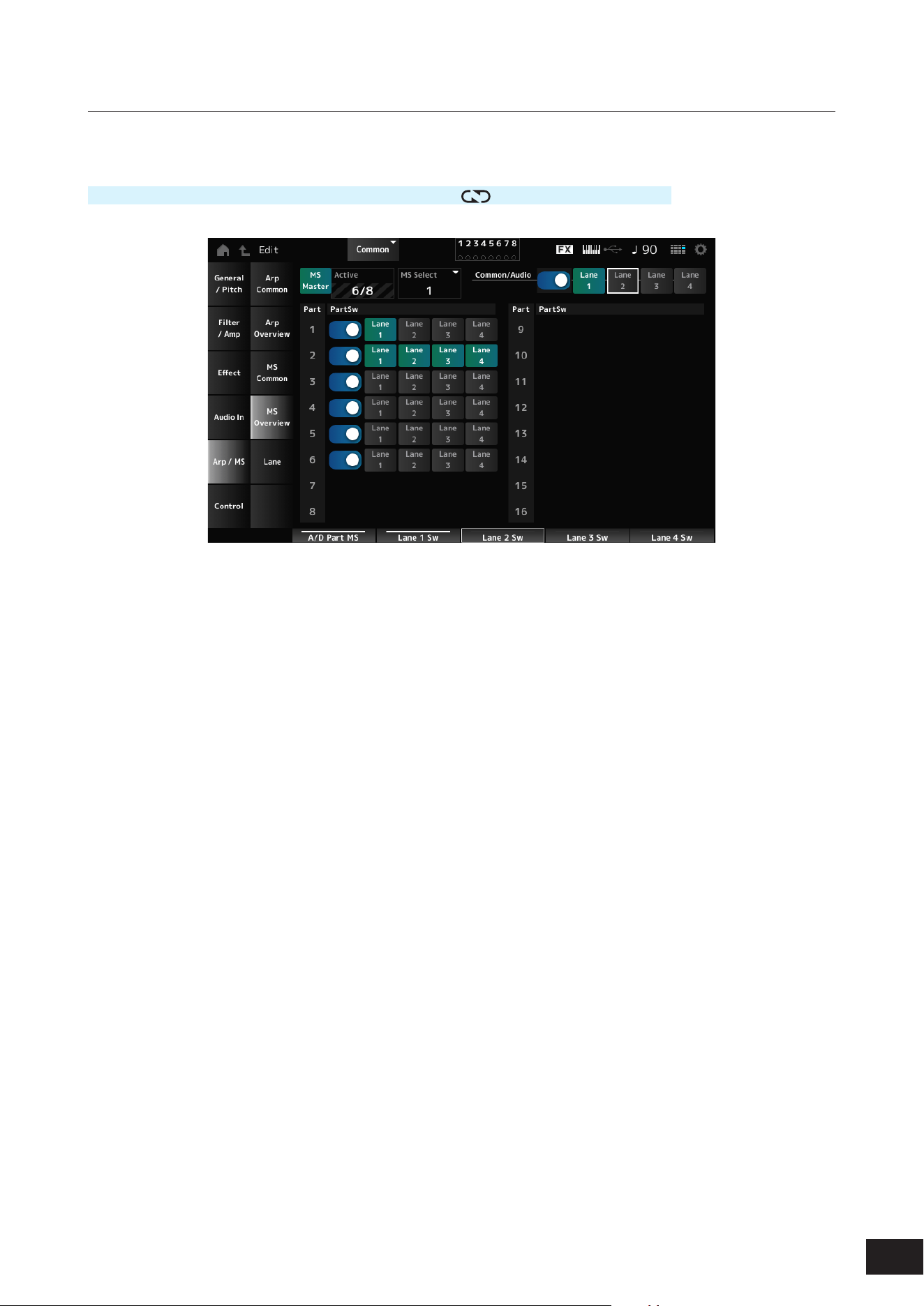
183
MODX M Operation Manual
MS Overview (Motion Sequencer Overview)
On the MS Overview screen, you can set the Motion Sequencer from the list of all Parts.
Operation
[PERFORMANCE (HOME)]
→
Common selection
→
[EDIT/ ]
→
Arp/MS
→
MS Overview
MS Master (Motion Seq Master Switch)
Sets the Motion Sequencer for the entire Performance on or off.
This switch is linked to the [MSEQ] buttons on the top panel.
Settings: Off, On
Active (Active Motion Sequencer)
Shows the number of Lane switches set to On.
The number shown on the right side of the slash (/) indicates the maximum number of Lanes you can simultaneously set
to On.
MS Select (Motion Sequence Select)
Changes the Motion Sequence selection.
Settings: 1–8
PartSw (Motion Sequencer Part Switch)
Sets the Motion Sequencer on or off for each Part.
Settings: Off, On
Lane Switch
Sets each Lane on or off.
You can use up to four Motion Sequencer lanes in one Part, or up to eight lanes in an entire Performance.
Settings: Off, On
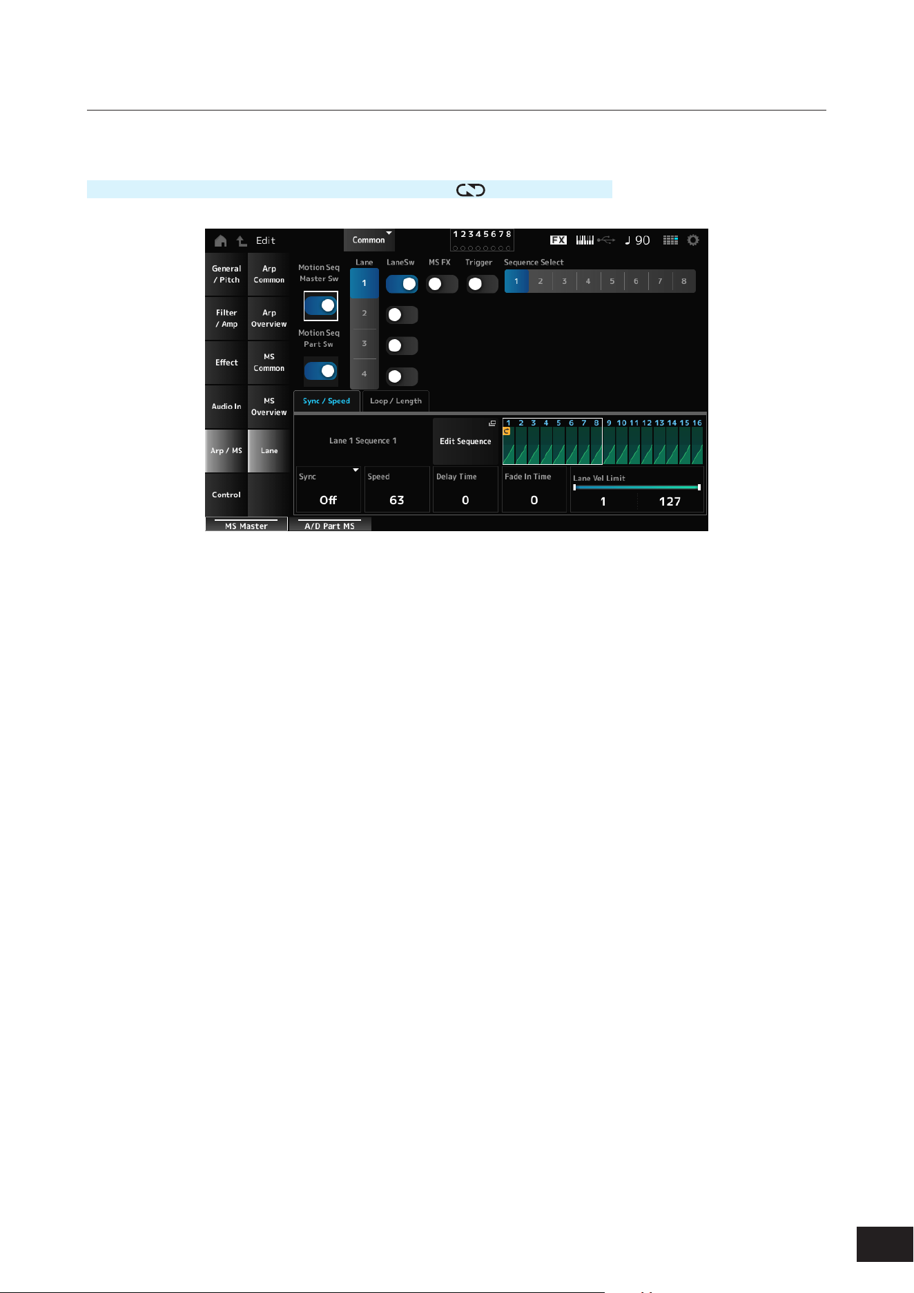
184
MODX M Operation Manual
Lane
On the Lane screen, you can set the parameters for each Motion Sequencer Lane.
Operation
[PERFORMANCE (HOME)]
→
Common selection
→
[EDIT/ ]
→
Arp/MS
→
Lane
Motion Seq Master Sw (Motion Sequencer Master Switch)
Sets the Motion Sequencer for the entire Performance on or off.
Settings: Off, On
Motion Seq Part Sw (Motion Sequencer Part Switch)
Sets the Motion Sequencer of the Part on or off.
Settings: Off, On
Lane (Lane Select)
Shows the parameters for the selected Lane.
Settings: 1–4
LaneSw (Lane Switch)
Sets each Lane on or off.
You can use up to four Motion Sequencer lanes in one Part, or up to eight lanes in an entire Performance.
When set to Off, the parameters for that lane will not be shown.
Settings: Off, On
MS FX (Lane FX Receive)
Sets the selected Lane to receive the signals from the knobs for changing the Motion Sequencer parameters.
Settings: Off, On
Trigger (Lane Trigger Receive)
Sets the selected Lane to receive the signals from the [MSEQ TRIGGER] button.
When set to On, the Motion Sequence will not be played back unless you press the [MSEQ TRIGGER] button.
Settings: Off, On
Sequence Select (Motion Sequence Select)
Changes the Motion Sequence selection.
Settings: 1–8
Target Sequence
Shows the selected Lanes and sequences.

185
MODX M Operation Manual
Sync/Speed Tabs
Sync (Lane Sync)
Sets the playback of the Motion Sequence set to the Destinationin the Control Assign screen to synchronize to the
Performance tempo or beat.
Settings: Off, Tempo, Beat, Lane1 (when Lane2–4 are selected)
Off: Plays back the Lane Motion Sequencer alone
Tempo: Plays back the Lane Motion Sequencer at the Performance tempo.
Beat: Plays back the Motion Sequencer in sync with the beat
Lane1: Plays back the Lane Motion Sequencer in sync with Lane 1
• When Sync is set to Off
Speed (Lane Speed)
Sets the playback speed for the Motion Sequence.
This parameter is available when Sync is set to Off.
Settings: 0–127
Delay Time (A/D Part Motion Seq Lane Key On Delay Time Length)
Sets the delay time for starting the playback of the Motion Sequence.
Settings: 0–127
Fade In Time (A/D Part Motion Seq Lane Fade In Time Length)
Sets the time for the Motion Sequence to reach maximum amplitude.
Settings: 0–127
• When Sync is set to something other than Off
Unit (A/D Part Motion Seq Lane Unit Multiply)
Sets the percentage for stretching or compressing the Motion Sequencer playback time for the selected Lane.
This parameter is available when Sync is set to Tempo or Beat.
Settings: 50%, 66%, 75%, 100%, 133%, 150%, 200%, 266%, 300%, 400%, 600%, 800%, 1200%, 1600%, 2400%, 3200%, 6400%,
Common
200%: The playback time is doubled, and the tempo is halved
100%: The playback time is kept unchanged
50%: The playback time is halved, and the tempo is doubled
Common: The value set in the Unit Multiply common to all Parts is applied
Delay Steps (A/D Part Motion Seq Lane Key On Delay Step Length)
Sets the delay time for starting the playback of the Motion Sequence when Sync is set to Tempo or Beat.
Settings: 0–32
Fade In Steps (A/D Part Motion Seq Lane Fade In Step Length)
Sets the time to reach the maximum amplitude for the Motion Sequence when Sync is set to Tempo, Beat, or Lane1.
Settings: 0–32
Lane Vel Limit (Lane Velocity Limit)
Sets the velocity range (lowest and highest values) for playing back the Motion Sequence of the selected Lane.
This parameter is available when Sync is set to Off, Tempo, or Beat.
When the Velocity Limit is set to a range from the highest value to the lowest value, the Motion Sequence will be played
back in two velocity ranges: from the maximum to the highest value, and from the lowest value to the minimum.
Settings: 1–127
Edit Sequence
The Motion Sequence Edit screen will open.
Motion Seq Step n Value
Shows the step curve for the selected sequence.
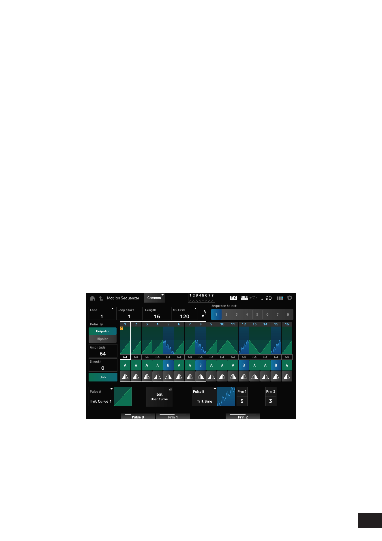
186
MODX M Operation Manual
Loop/Length Tabs
Key On Reset (Lane Key On Reset)
Resets the Motion Sequence playback when you press any key on the keyboard.
This parameter is available when Sync is set to Off, Tempo, or Beat. This parameter is not available when Trigger is set
to On.
Settings: Off, Each-On, 1st-On
Each-On: Each time you play any note, the sequence will be reset and the playback starts from the beginning
1st-On: Playback starts from the beginning at the rst note you play. The sequence will not be reset when a second note is
played while the rst note is being played.
Loop (Lane Loop)
Sets the Motion Sequence to loop playback (in repeats) or one-shot playback.
This parameter is available when Sync is set to Off, Tempo, or Beat.
Settings: Off, On
Loop Start (Lane Loop Start)
Species the starting point for the loop playback of the Motion Sequence.
Settings: 1–16 (should be below the Length setting)
Length (Motion Seq Length)
Sets the number of steps in the Motion Sequence.
Settings: 1–16 (should be above the Loop Start setting)
MS Grid (Motion Sequencer Grid)
Sets the length of a step in the Motion Sequence.
Settings: 60, 80, 120, 160, 240, 320, 480
Motion Sequence Edit
Opens the setting screen for the Motion Sequence.
You can create a sequence of up to 16 steps.
Loop Start (Lane Loop Start)
Species the starting point for the loop playback of the Motion Sequence.
Settings: 1–16 (should be below the Length setting)
Length (Motion Sequence Length)
Sets the Motion Sequence length.
Settings: 1–16 (should be above the Loop Start setting)

187
MODX M Operation Manual
MS Grid (Motion Sequencer Grid)
Sets the length of a step in the Motion Sequence.
Settings: 60, 80, 120, 160, 240, 320, 480
Sequence Select (Motion Sequence Select)
Changes the Motion Sequence type selection.
Settings: 1–8
Lane Select
Changes the Lane selection.
Settings: 1–4
Polarity (Motion Sequence Polarity)
Sets the polarity of the Motion Sequence.
Settings: Unipolar, Bipolar
Unipolar: Only positive values are used for the parameter change
Bipolar: Both positive and negative values are used for the parameter change
Amplitude (Motion Sequence Amplitude)
Sets the degree of changes in the Motion Sequence.
Settings: 0–127
Smooth (Motion Sequence Smoothness)
Sets the smoothness of the changes in the Motion Sequence over time.
Settings: 0–127
Job
Calls up the Job menu.
• Store Sequence
Saves (stores) the edited Motion Sequence.
• Load Sequence
Loads the Motion Sequence.
• Copy Sequence
Copies the Motion Sequence.
Motion Sequence Step Value
Sets the value for each step in the Motion Sequence.
You can use Control sliders 1 to 8 to change the values for Steps 1 to 8 and Steps 9 to 16, depending on the cursor
position.
Settings: 0–127
Motion Sequence Step Type
Sets the type and direction of each step in the Motion Sequence.
Settings: A, B, Reverse A, Reverse B
Pulse A (Motion Sequence Step Curve Type A)
Pulse B (Motion Sequence Step Curve Type B)
Selects a parameter change curve for Pulse A and Pulse B.
Use the Motion Sequence Step Type to select which of the curve types to use for each step.
The vertical axis represents the time while the horizontal axis represents the step value.
Settings: Standard, Sigmoid, Threshold, Bell, Dogleg, FM, AM, M, Discrete Saw, Smooth Saw, Triangle, Square, Trapezoid, Tilt Sine,
Bounce, Resonance, Sequence, Hold, Harmonic, Steps (When a preset bank is selected)
Init Curve 1–32 (When a user bank is selected)
Curve within Library 1–24 (When loading a Library le)

188
MODX M Operation Manual
Prm 1 (Motion Sequence Step Curve Parameter 1)
Prm 2 (Motion Sequence Step Curve Parameter 2)
Adjusts the shape of the step curve in the Motion Sequence. Also, the range for the parameter value differs depending on
the Curve Type.
This setting is not available depending on the Curve Type.
Control (Motion Sequence Step Curve Shape Control Switch)
Enables or disables the use of the knobs for controlling the step curve shape of the Motion Sequence.
Shown only when MS FX (Lane FX Receive) is set to On. This setting is not available depending on the Curve Type.
Settings: Off, On
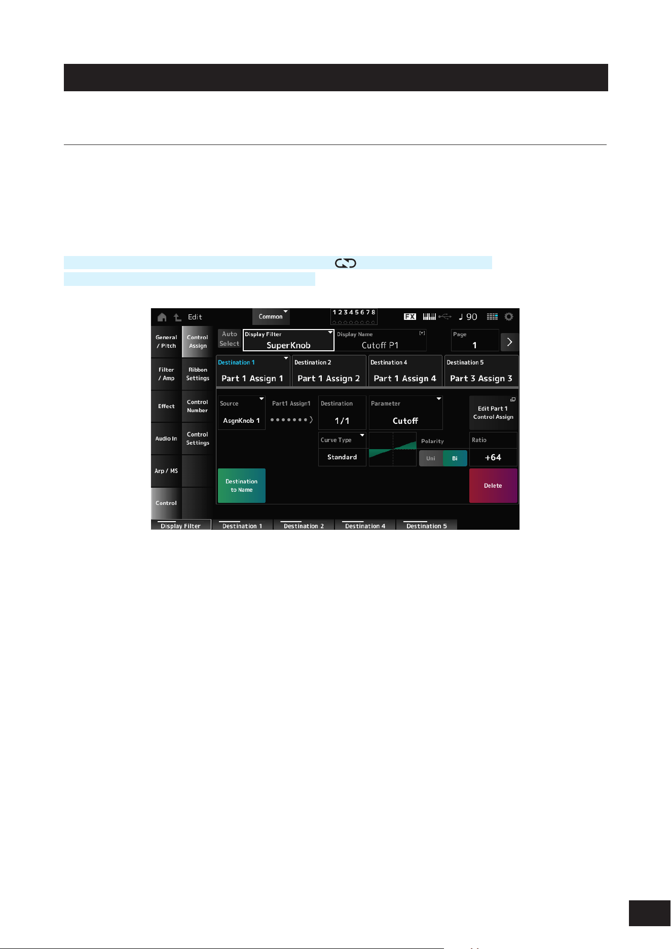
189
MODX M Operation Manual
Control
Control Assign
On the Control Assign screen, you can set the Controllers for the Part.
By assigning a parameter (Destination) to a controller (Source), you can control the sound in a large variety of ways. You
can use physical controllers such as the Pitch Bend wheel and knobs as well as the Motion Sequencer and Envelope
Follower.
Up to 32 controllers can be assigned simultaneously to a Part.
Operation
[PERFORMANCE (HOME)]
→
Common selection
→
[EDIT/ ]
→
Control
→
Control Assign
Tap Edit Super Knob on Motion Control
→
Super Knob
Auto Select
Switches the Auto Select setting of the Display Filter on or off.
When set to On, moving the controller you wish to set to Source automatically sets the controller to the Display Filter.
Settings: Off, On
Display Filter
Selects the controller for showing the settings on the screen.
When you select Super Knob, all settings for Knobs 1 to 8 having the Super Knob Link set to On will be shown.
Settings: PitchBend, ModWheel, Ch. AT, FootCtrl 1, FootCtrl 2, FootSwitch, Ribbon, Breath, AsgnKnob 1–8, Super Knob, AsgnSw 1,
AsgnSw 2, MS Lane 1–4, EnvFollow 1–16, EnvFollowAD, EnvFollowMst, All
Display Name (Assignable Knob Name)
This allows you to enter a new name for Knobs 1 to 8. This parameter is not shown when Source is set to something other
than AsgnKnob 1–8.
Edit Pitch Bend
General/Pitch
→
Pitch will open. This parameter is not shown when Source is set to something other than PitchBend.
Edit Motion Sequencer
Opens Arp/MS
→
Lane. This parameter is not shown when Source is set to something other than MS Lane 1–4.
Edit Envelope Follower
Opens the settings screen for Envelope Follower. This parameter is not shown when Source is set to something other
than EnvFollow 1–16, EnvFollowAD, or EnvFollowMst.

190
MODX M Operation Manual
Destination
Sets the parameter to the Destination. Tap [+] to add a Destination.
When Source is set to AsgnKnob 1–8, Part1–16 Assign1–8 is added to the settings. In that case, Curve Type and Curve
Ratio are not available.
Source
Sets the controller for controlling the parameters set to the Destination.
When Destination is set to Part1–16 Assign1–8, onlu AsgnKnob 1–8 will be available. Other controllers cannot be used.
Settings: PitchBend, ModWheel, AfterTouch, FootCtrl 1, FootCtrl 2, FootSwitch, Ribbon, Breath, AsgnKnob 1–8,
AsgnSw 1, AsgnSw 2, MS Lane 1–4, EnvFollow 1–16, EnvFollowAD, EnvFollowMst
Destination to Name
Copies the parameters set to Destination to Display Name.
This parameter is not shown when Source is set to something other than AsgnKnob 1–8.
Delete
Deletes the selected Destination.
Destination (Part Assignable Knob Destination)
Sets the parameter to show when you try to set Part1–16 Assign1–8 to the Destination and multiple Destinations are
already assigned to Part Assign.
Parameter (Part Assignable Knob Parameter)
Sets the Part parameter to the Destination.
Settings: Refer to the Data List
The parameters shown below appear only when Destination 1–32 is set to Part1–16 Assign1–8. Also, only the shortcut
buttons are available on the screens when Part Knobs 1–8 cannot be found in Destination.
Edit (Part No.) Control Assign
Opens the Control Assign screen for the selected Part.
Curve Type
Sets the change curve of the parameter set to Destination.
The horizontal axis represents the controller value set in Source while the vertical axis represents the parameter value.
Settings: Standard, Sigmoid, Threshold, Bell, Dogleg, FM, AM, M, Discrete Saw, Smooth Saw, Triangle, Square, Trapezoid, Tilt Sine,
Bounce, Resonance, Sequence, Hold, Harmonic, Steps (When a preset bank is selected)
Init Curve 1–32 (When a user bank is selected)
Curve within Library 1–24 (When loading a Library le)
Polarity (Curve Polarity)
Sets the polarity of the curve set in Curve Type.
Settings: Uni, Bi
Uni: Parameter changes occur only within the positive range or the negative range according to the curve shape
Bi: Parameter changes occur both in positive and negative ranges according to the curve shape
Ratio (Curve Ratio)
Sets the ratio of the parameter values.
Settings: −128–+0 –+127
Param 1 (Curve Parameter 1)
Param 2 (Curve Parameter 2)
Adjusts the curve shape. This setting is not available depending on the Curve Type.
Edit User Curve
Opens the setting screen for User Curve.
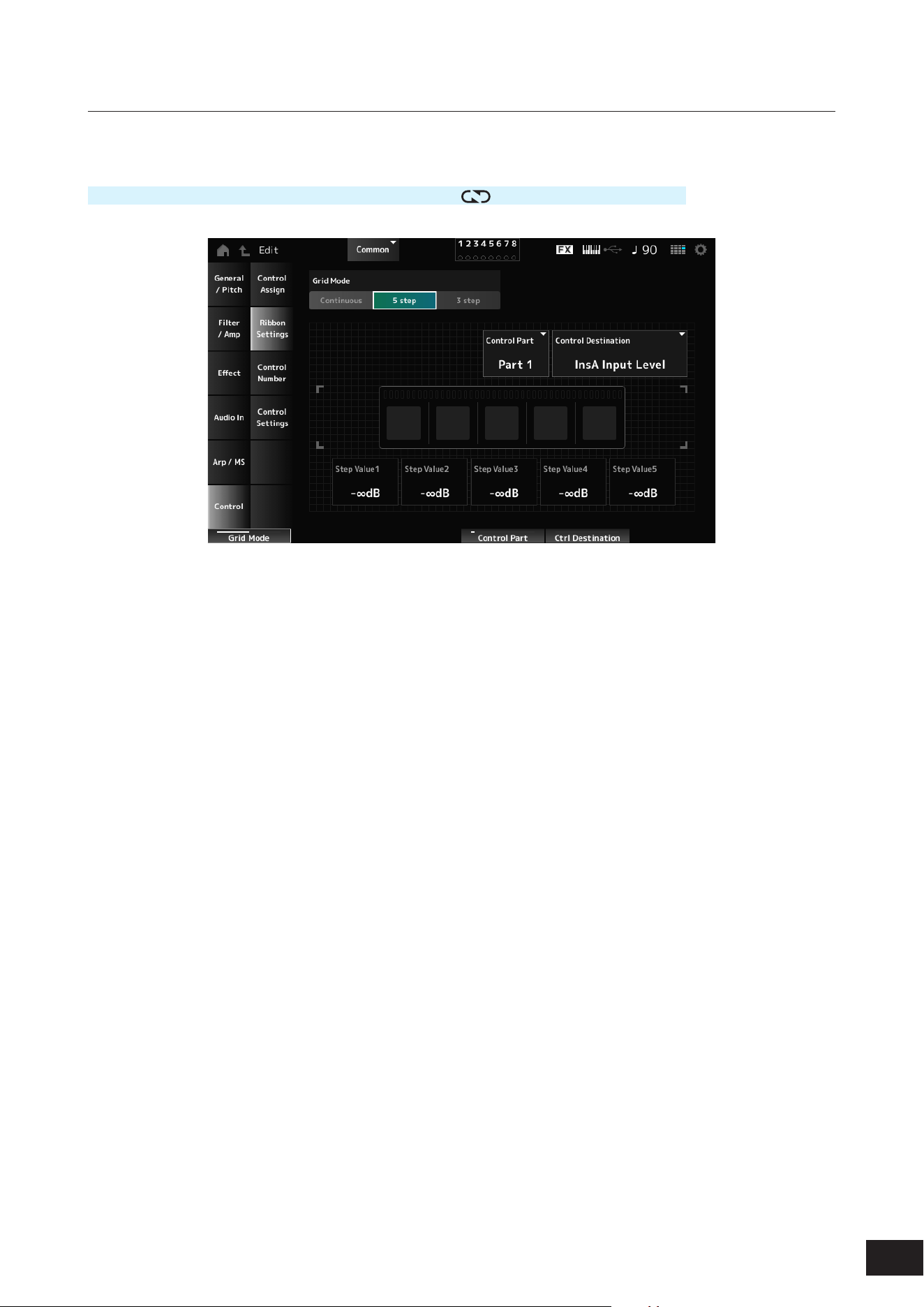
191
MODX M Operation Manual
Ribbon Settings
Sets the Ribbon controller.
Operation
[PERFORMANCE (HOME)]
→
Common selection
→
[EDIT/ ]
→
Control
→
Ribbon Settings
Ribbon Grid Mode
Sets the grid mode for the Ribbon controller.
Settings: Continuous, 5 step, 3 step
NOTE
Set to Continuous if you wish to use the Ribbon Controller setting you have set on the Control Assign screen.
Continuous mode
Ribbon Mode (Ribbon Controller Mode)
Sets the way the Ribbon Controller functions.
Settings: Hold, Reset
Hold: Retains the value of the position at which you release your nger from the Ribbon Controller.
Reset: Automatically resets the value to the mid position when you release your nger from the Ribbon Controller.
5 step mode, 3 step mode
Control Part
Selects the Part to be controlled with the Ribbon Controller.
Settings: Common, Part 1–16
Control Destination
Settings: Refer to the Control Box Destination in the Data List
Step Value 1–5
Settings: Depends on the Destination
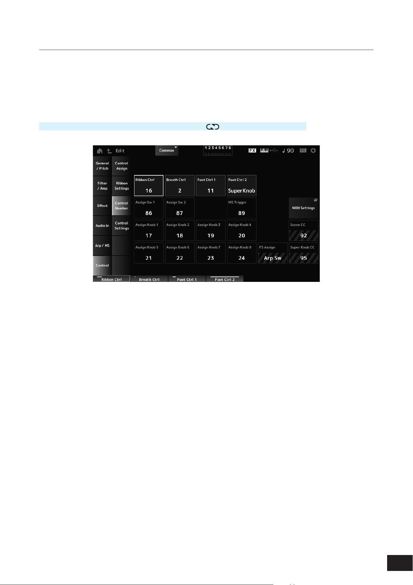
192
MODX M Operation Manual
Control Number
Sets the Control Change number for the entire Performance.
You can assign specic MIDI Control Change numbers to the Knobs on the top panel and controllers on the external
device.
NOTE
As for controllers not included on this instrument, you can use an external sequencer or external MIDI controllers.
Operation
[PERFORMANCE (HOME)]
→
Common selection
→
[EDIT/ ]
→
Control
→
Control Number
Ribbon Ctrl (Ribbon Controller Control Number)
Sets the Control Change number generated by the operation of the Ribbon Controller.
When this instrument receives a MIDI Control Change message of the number set with this parameter from the external
device, the message is treated the same as the operation of the built-in Ribbon Controller.
Settings: Off, 1–95
Breath Ctrl (Breath Controller Control Number)
Sets the Control Change number for the Breath Controller to be received from the external device.
When this instrument receives a MIDI Control Change message of the number set with this parameter from the external
device, the message is treated the same as the operation of the Breath Controller.
Settings: Off, 1–95
Foot Ctrl 1 (Foot Controller 1 Control Number)
Foot Ctrl 2 (Foot Controller 2 Control Number)
Sets the Control Change number generated by the operation of the Foot Controller connected to the FOOT
CONTROLLER jack.
When this instrument receives a MIDI Control Change message of the number set with this parameter from the external
device, the message is treated the same as the operation of the Foot Controller.
Settings: Off, 1–95, Super Knob
Assign Sw 1 (Assignable Switch 1 Control Number)
Assign Sw 2 (Assignable Switch 2 Control Number)
Sets the Control Change number generated by the operation of the [ASSIGN 1] and [ASSIGN 2] buttons.
When this instrument receives a MIDI Control Change message of the number set with this parameter from the external
device, the message is treated the same as the operation of the [ASSIGN 1] and [ASSIGN 2] buttons.
Settings: Off, 1–95

193
MODX M Operation Manual
MS Trigger (Motion Sequencer Trigger Switch Control Number)
Sets the Control Change number generated by the operation of the [MSEQ TRIGGER] button.
When this instrument receives a MIDI Control Change message of the number set with this parameter from the external
device, the message is treated the same as the operation of the [MSEQ TRIGGER] button.
Settings: Off, 1–95
MIDI Settings
Opens the MIDI settings screen. The same screen can be opened from [UTILITY]
→
Settings
→
MIDI I/O.
Assign Knob (Assignable Knob Control Number)
Sets the Control Change number generated by the operation of Knobs 1 to 8.
When this instrument receives a MIDI Control Change message of the number set with this parameter from the external
device, the message is treated the same as the operation of Knobs 1 to 8.
Settings: Off, 1–95
FS Assign (Foot Switch Assign Control Number)
Shows the Control Change number generated by the operation of the footswitch connected to the FOOT SWITCH
[ASSIGNABLE] jack. When this instrument receives a MIDI Control Change message of the number set with this
parameter from the external device, the message is treated the same as the operation of the footswitch.
Scene CC (Scene Control Change Number)
Shows the Control Change number generated by the operation of the SCENE buttons. When this instrument receives a
MIDI Control Change message of the number set with this parameter from the external device, the message is treated the
same as the operation of the SCENE buttons.
Super Knob CC (Super Knob Control Change Number)
Shows the Control Change number generated by the operation of the Super Knob. When this instrument receives a MIDI
Control Change message of the number set with this parameter from the external device, the message is treated the
same as the operation of the Super Knob.
NOTE
• When Scene CC and Super Knob CC are set to Off, System Exclusive (SysEx) is used for handling MIDI messages.
• FS Assign, Scene CC, and Super Knob CC are used for the entire instrument. If desired, change these settings from the Utility MIDI
I/O screen.
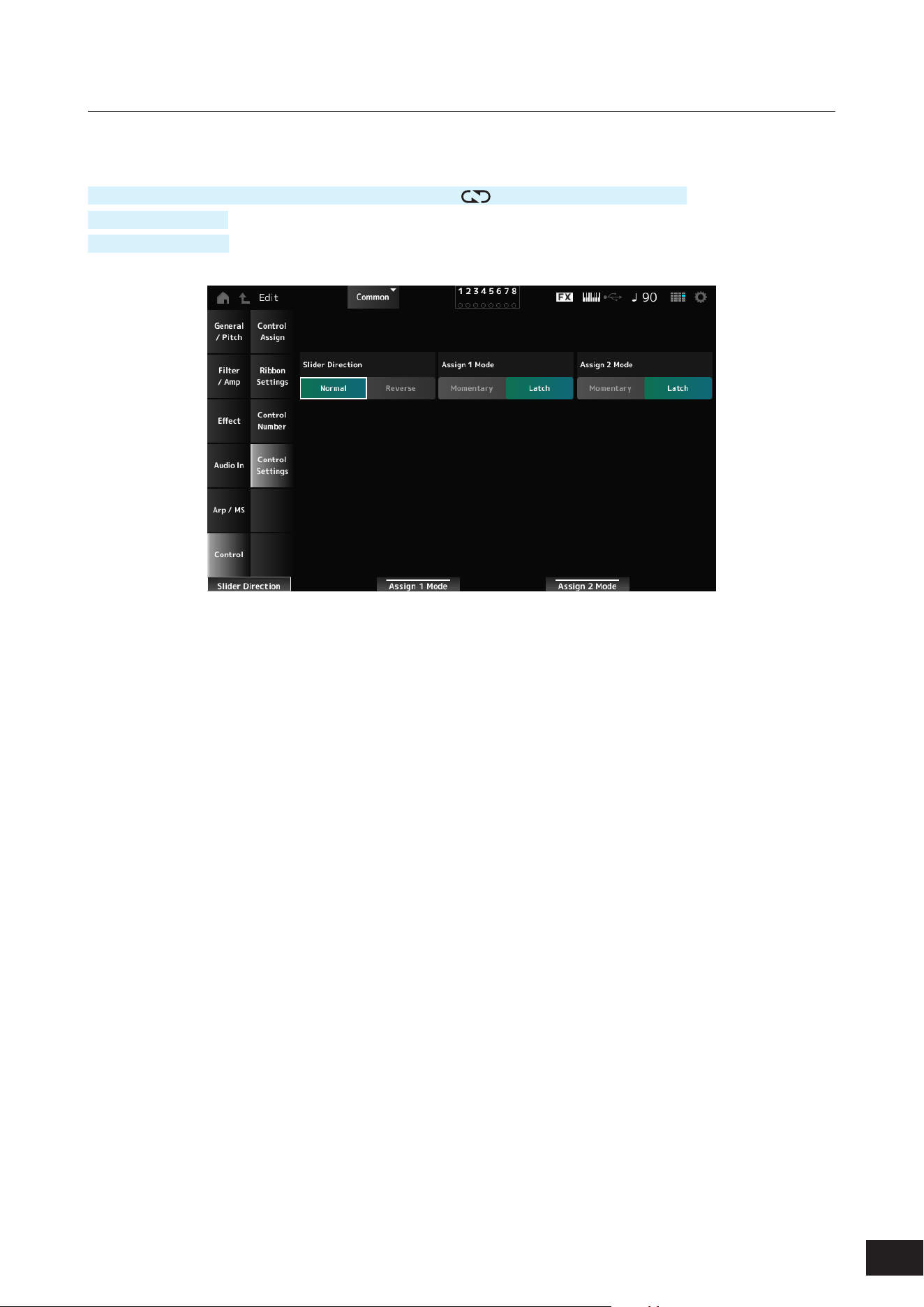
194
MODX M Operation Manual
Control Settings
Sets the controller mode.
Operation
[PERFORMANCE (HOME)]
→
Common selection
→
[EDIT/ ]
→
Control
→
Control Settings
[SHIFT] + [ASSIGN 1]
[SHIFT] + [ASSIGN 2]
Slider Direction Part 1–8
Sets the direction of the Control sliders 1 to 8 when the slider Mode is set to PART.
Settings: Normal (up from the bottom), Reverse (down from the top)
Assignable Switch 1 Mode
Assignable Switch 2 Mode
Sets the [ASSIGN 1] and [ASSIGN 2] buttons for the Latch or Momentary setting.
Settings: Latch, Momentary
Latch: Sets to On when you press the button and sets to Off when you press the button again.
Momentary: Sets to On while you are holding down the button and sets to Off when you release the button.
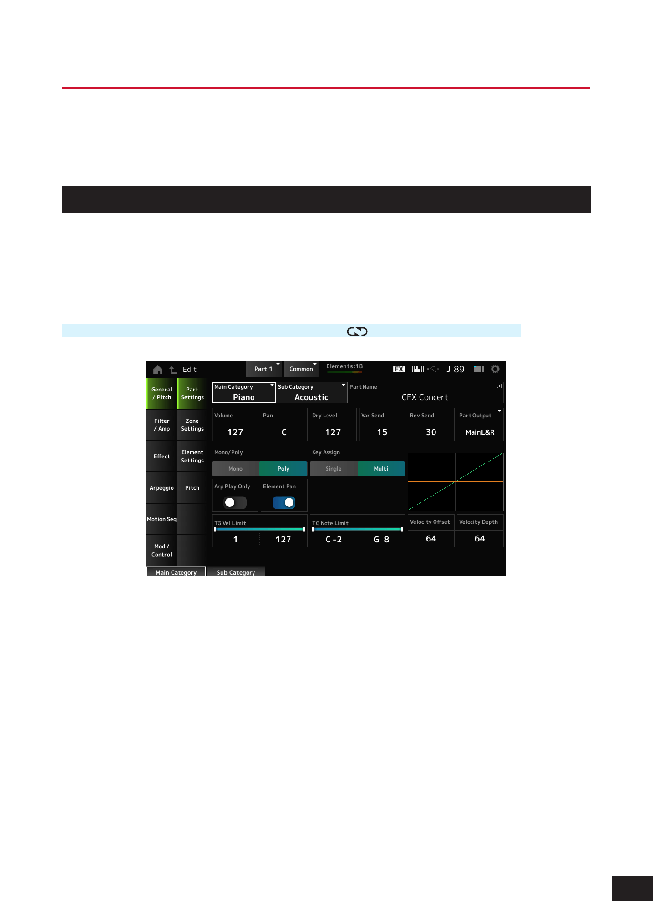
195
MODX M Operation Manual
Part Edit (AWM2) Part Common Edit Screens
A Normal Part (AWM2) consists of up to 128 elements.
Part Edit (AWM2) includes Part Common Edit (for setting parameters for the entire Part) and Element Edit (for setting
parameters for each Element in the Part).
General/Pitch
Part Settings
On the Part Settings screen, you can set general parameters (such as the Part names and tone generation system) for
the Part.
Operation
[PERFORMANCE (HOME)]
→
Part Common selection
→
[EDIT/ ]
→
General/Pitch
→
Part Settings
Main Category (Part Main Category)
Sub Category (Part Sub Category)
Sets the Main category and Sub category of the selected Part.
Settings: Refer to the Data List
Part Name
You can save the Part you are editing under a new name, You can use up to 20 alphanumeric characters.
Volume
Sets the volume of the selected Part.
Settings: 0–127
Pan
Adjusts the Pan position (in the stereo eld) of the selected Part.
Settings: L63–C (center)–R63

196
MODX M Operation Manual
Dry Level
Sets the Dry Level of the selected Part. This parameter is available only when Part Output is set to MainL&R.
Settings: 0–127
Var Send (Variation Send)
Sets the Variation Send of the selected Part. This parameter is available only when Part Output is set to MainL&R.
Settings: 0–127
Rev Send (Reverb Send)
Sets the Reverb Send of the selected Part. This parameter is available only when Part Output is set to MainL&R.
Settings: 0–127
Part Output (Part Output Select)
Sets the output destination for the audio signals of the selected Part.
Settings: MainL&R, (AsgnL&R), USB Stereo, (AsgnL), (AsgnR), USB mono, Off
MainL&R: Outputs in stereo (two channels) to the OUTPUT [L/MONO] and OUTPUT [R] jacks.
USB Stereo: Outputs in stereo (channels 1 and 2, to channels 7 and 8) to the USB [TO HOST] terminal
USB mono: Outputs in mono (channels 1 to 8) to the USB [TO HOST] terminal
Off: No output of the audio signal for the Part.
NOTE
The settings for data compatibility with MONTAGE M are shown below. They are considered Off when set.
• AsgnL&R
• USB Stereo: USB9&10 – USB29&30
• USB mono: USB9 – USB30
• AsgnL
• AsgnR
Mono/Poly
Sets the tone generation mode of the current Part. Mono is for playing single notes, and Poly is for playing multiple
simultaneous notes.
When using the Mono setting for playing the keyboard in Legato, you can create a smooth transition of sounds from one
note to another.
Settings: Mono, Poly
Key Assign (Key Assign Mode)
Sets how sound is produced when the internal tone generator receives Note On messages of the same sound twice (or
more) in a row.
The Multi setting is recommended for most cases. However, the Multi setting uses up many notes in the maximum
polyphony, so it is recommended to change to Single if sounds in other Parts are dropped or not played properly.
Settings: Single, Multi
Single: Stops the rst note and then plays the same note again. This is convenient for repeating the same note on the same
channel
Multi: Plays the second note over the rst note. The Multi setting makes rolls sound natural, especially crash cymbals or other
percussion instruments having a long decay
Arp Play Only (Arpeggio Play Only)
Sets the Part to be played only with the Arpeggio.
Any Part set to On will be played by the Note On messages sent from the Arpeggio.
Settings: Off, On
Element Pan (Element Pan Switch)
Sets the Pan to On or Off from the Element Edit.
When set to Off, the Pan in the Element Edit will be set to C (center).
Settings: Off, On
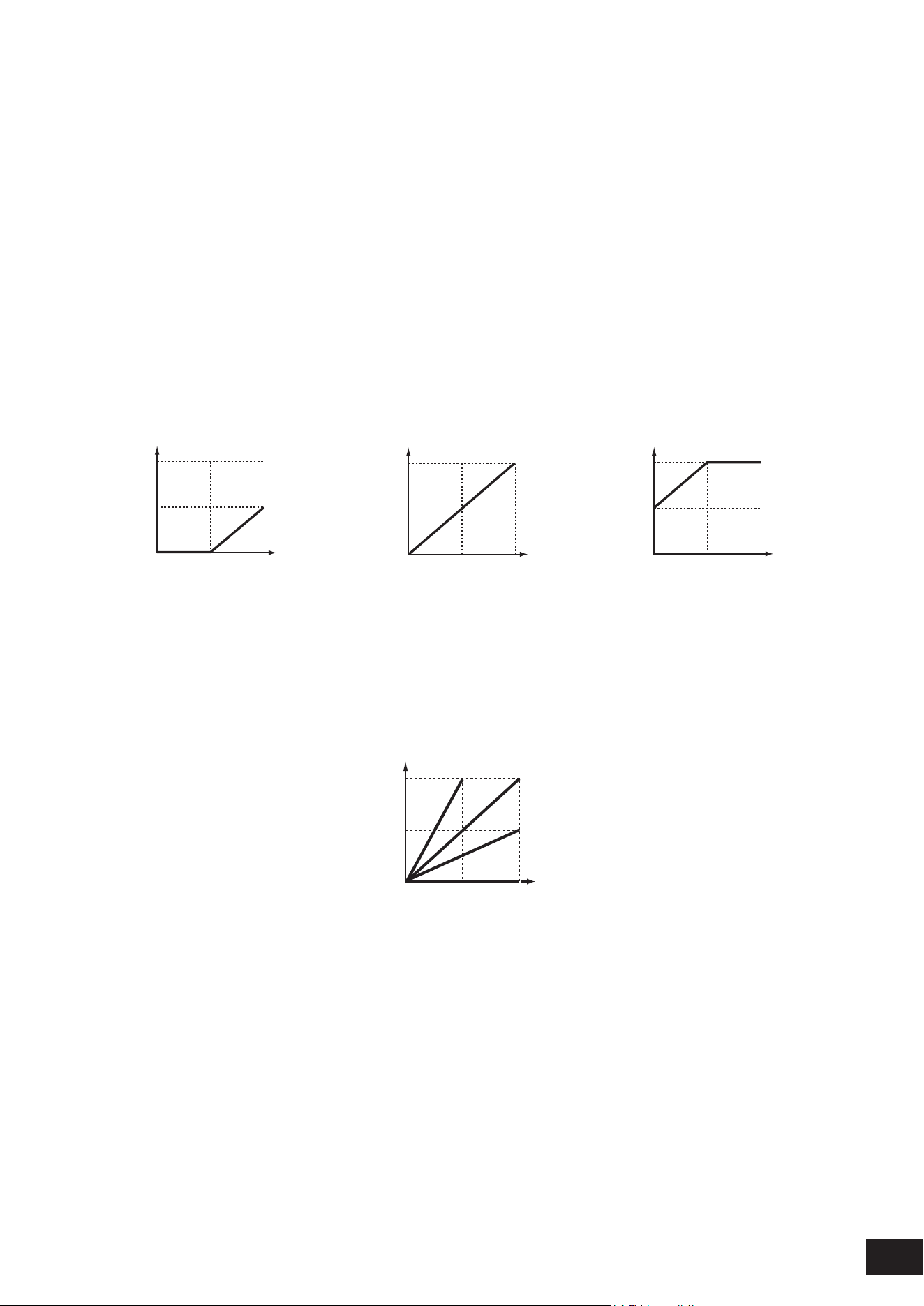
197
MODX M Operation Manual
TG Note Limit (Note Limit)
Sets the note range (lowest and highest notes) for the Part.
When the rst note of Note Limit is set higher than the second (for example, C5 to C4), the notes in the ranges C−2 to C4
and C5 to G8 will be played.
Settings: C−2–G8
TG Vel Limit (Velocity Limit)
Sets the velocity range (lowest and highest values) for the Part.
When this is set so that the higher value is rst and the lower value is second (for example, 93 to 34), the notes are played
only for velocities of 1 to 34 and 93 to 127.
Settings: 1–127
Velocity Offset (Velocity Sensitivity Offset)
Increases or decreases the velocity value that is sent to the internal tone generator.
Settings: 0–127
When Velocity Depth = 64
and Velocity Offset = 32
When Velocity Depth = 64
and Velocity Offset = 64
When Velocity Depth = 64
and Velocity Offset = 96
127
0 12764
127
64
127
0
12764
127
0
(1)
(2)
(1)
(2)
(1)
(2)
127
0 12764
127
64
127
0
12764
127
0
(1)
(2)
(1)
(2)
(1)
(2)
127
0 12764
127
64
127
0
12764
127
0
(1)
(2)
(1)
(2)
(1)
(2)
(1) Actual resulting velocity (affecting the tone generator)
(2) Velocity with which you play a note
Velocity Depth (Velocity Sensitivity Depth)
Sets how the level of the velocity value (sent to the internal tone generator) responds to Velocity or the strength of the
keystroke.
Settings: 0–127
When Velocity Depth = 64
127
0
12764
(1)
Depth = 127
Depth = 64
Depth = 32
Depth = 0
(2)
(1) Actual resulting velocity (affecting the tone generator)
(2) Velocity with which you play a note
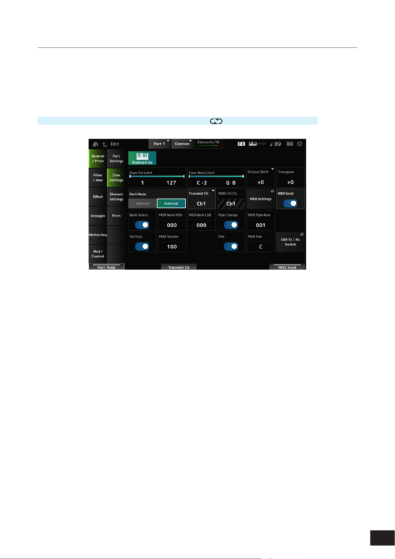
198
MODX M Operation Manual
Zone Settings
On the Zone Settings screen, you can set the parameters for the Zone function.
This function allows you to divide the entire keyboard into a maximum of eight sections (Zones) and independently assign
a separate channel to each Zone.
This way, you only need one keyboard to play the sounds of multiple keyboards. You can play multiple Parts on an
external multi-timbral sound module or play both the internal tone generator and any connected external sound modules.
Operation
[PERFORMANCE (HOME)]
→
Part Common selection
→
[EDIT/ ]
→
General/Pitch
→
Zone Settings
Keyboard Sw (Keyboard Control Switch)
You can set which Parts will play simultaneously by turning each Part's Keyboard Sw (Keyboard Control Switch) on or off.
When you select a Part with Common or Keyboard Sw set to On and play the keyboard, the Parts with Keyboard Sw set
to On will play simultaneously.
If the Keyboard Sw for the Part is set to Off, when you play the keyboard with that Part selected, those sounds will be
played.
Settings: Off, On
Zone Vel Limit (Zone Velocity Limit)
Sets the velocity range (lowest and highest values) for the Zone.
When this is set so that the higher value is rst and the lower value is second (for example, 93 to 34), the notes are played
only for velocities of 1 to 34 and 93 to 127.
Settings: 1–127
Zone Note Limit
Sets the note range (lowest and highest notes) for the Zone.
When the rst note of Note Limit is set higher than the second (for example, C5 to C4), the notes in the ranges C−2 to C4
and C5 to G8 will be played.
Settings: C−2–G8
Octave Shift
Shifts the pitch of the zone in octaves.
Settings: −3–+0 (standard)–+3

199
MODX M Operation Manual
Transpose
Shifts the pitch of the zone in semitones.
Settings: −11–+0 (standard)–+11
Part Mode
Switches the Part Mode.
Settings: Internal, External
Internal: Mode that uses the built-in sound engine of the instrument
External: Uses the external sound generator. Any Part set to External does not receive MIDI messages from the external
device
Tx/Rx Ch (Transmit/Receive Channel)
Sets the channel for transmitting and receiving MIDI messages when the Part Mode is set to Internal.
Settings: Ch1–Ch16, Off
Transmit Ch
Sets the channel for transmitting and receiving MIDI messages for the Zone when the Part Mode is set to External.
Settings: Ch1–Ch16
MIDI I/O Ch (MIDI Input/Output Channel)
Shows the channel for controlling the Part set to Common and the Part with the Keyboard Sw set to On.
This setting is common to the entire instrument. The setting can be changed on the Utility MIDI Settings screen.
When using Tx/Rx Ch and Transmit Ch, do not use the same channel specied in MIDI I/O Ch. If the same channel is
specied, the setting in MIDI I/O Ch will take priority.
Settings: Ch1–Ch16
MIDI Settings
Opens Settings
→
MIDI I/O on the Utility screen.
MIDI Send
When this parameter is set to On, the MIDI Bank MSB/LSB, MIDI Pgm Num, MIDI Volume, and MIDI Pan settings are
transmitted to the external device whenever those parameters are changed. However, the setting is not transmitted when
the corresponding transmit switch is set to Off.
This setting is common to all Performances and cannot be set individually for each Performance.
This parameter is available only when Part Mode is set to External.
Settings: Off, On
Bank Select (Transmit Bank Select)
The transmit switch for sending MIDI Bank MSB and MIDI Bank LSB to the external device.
This parameter is available only when Part Mode is set to External.
Settings: Off, On
MIDI Bank MSB
MIDI Bank LSB
Selects the bank for transmitting the Performance selection. This parameter is not available when Bank Select (Transmit
Bank Select) is set to Off.
This parameter is available only when Part Mode is set to External.
Settings: 000–127
Pgm Change (Transmit Program Change)
This is the transmit switch for sending Program Change messages to the external device.
This parameter is available only when Part Mode is set to External.
Settings: Off, On

200
MODX M Operation Manual
MIDI Pgm Num (MIDI Program Number)
Selects the Program Change number for transmitting the Performance selection.
This parameter is not available when Pgm Change (Transmit Program Change) is set to Off.
This parameter is available only when Part Mode is set to External.
Settings: 001–128
Vol/Exp (Transmit Volume/Expression)
This is the transmit switch for sending the volume setting to the external device.
This parameter is available only when Part Mode is set to External.
Settings: Off, On
MIDI Volume
Sets the volume for transmitting the Performance selection.
This parameter is available only when Part Mode is set to External.
Settings: 0–127
Pan (Transmit Pan)
This is the transmit switch for sending the Pan setting to the external device.
This parameter is available only when Part Mode is set to External.
Settings: Off, On
MIDI Pan
Sets the Pan for transmitting the Performance selection.
This parameter is not available when Pan (Transmit Pan) is set to Off.
Settings: L64–C (Center)–R63
Edit Tx/Rx Switch
Mod/Control
→
Tx/Rx Switch is displayed.
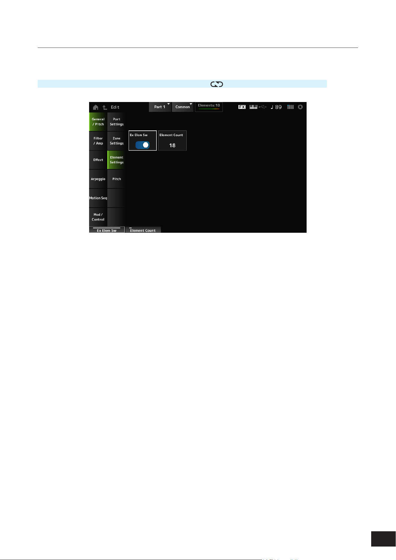
201
MODX M Operation Manual
Element Settings
Sets the maximum number of elements to use.
Operation
[PERFORMANCE (HOME)]
→
Part Common selection
→
[EDIT/ ]
→
General/Pitch
→
Element Settings
Ex Elem Sw (Extended Element Switch)
Enables the extension of Element capacity.
When set to Off, only up to eight elements are available.
Settings: Off, On
Element Count
Sets the maximum number of elements to use.
Settings: 8–128
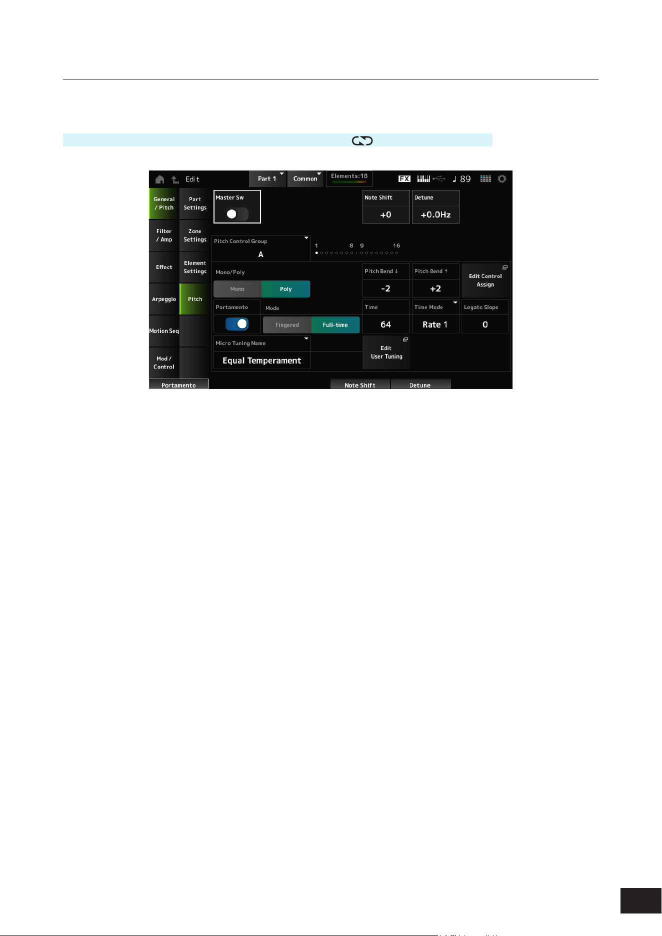
202
MODX M Operation Manual
Pitch
On the Pitch screen, you can set the pitch for the Part.
Operation
[PERFORMANCE (HOME)]
→
Part Common selection
→
[EDIT/ ]
→
General/Pitch
→
Pitch
Master Sw (Portamento Master Switch)
Portamento is a function for creating a smooth transition between two notes.
Sets Portamento on or off for Parts having the Portamento Part Switch set to On.
This switch is linked to the [PORTAMENTO] button on the top panel.
Settings: Off, On
Note Shift
Adjusts the pitch in semitones.
Settings: −48–+0–+48
Detune
Adjusts the pitch of the selected Part in 0.1 Hz increments.
By slightly shifting the pitch, you can detune the sound.
Settings: −12.8Hz–+0.0Hz–+12.7Hz
Pitch Control Group
Parts assigned to the same group are given the same pitch.
Mono/Poly
Sets the tone generation mode of the current Part. Mono is for playing single notes, and Poly is for playing multiple
simultaneous notes.
When using the Mono setting for playing the keyboard in Legato, you can create a smooth transition of sounds from one
note to another.
Settings: Mono, Poly
Pitch Bend
(Pitch Bend Range Lower)
Pitch Bend
(Pitch Bend Range Upper)
Sets the range of the changes created with the pitch bend wheel in semitones.
Settings: −48–+0–+24

203
MODX M Operation Manual
Edit Control Assign
Opens the Control Assign screen with the Display Filter set to PitchBend.
Portamento (Portamento Part Switch)
Sets Portamento on or off for the Part.
Settings: Off, On
Mode (Portamento Mode)
Sets the way Portamento is applied according to your keyboard performance.
Settings: Fingered, Full-time
Fingered: Portamento is applied only when you play legato (playing the next note before releasing the previous one)
Full-time: Portamento is applied at all times
Time (Portamento Time)
Sets the time length (or speed) for the pitch transition of Portamento for the Part.
Settings: 0–127
Time Mode (Portamento Time Mode)
Sets how the pitch changes over time.
Settings: Rate 1, Time 1, Rate 2, Time 2
Rate 1: Pitch changes at a specic rate.
Time 1: Pitch changes at a specic time.
Rate 2: Pitch changes at a specic rate within an octave.
Time 2: Pitch changes at a specic time within an octave.
Legato Slope (Portamento Legato Slope)
Adjusts the attack of the legato (playing the next note before releasing the previous one) when Mono/Poly is set to Mono.
When set to Mono, the attack of the note may sound unnatural depending on the attack speed of the waveform assigned
to the Part. By setting this parameter low for sounds with short attacks and high for sounds with long attacks, you can
adjust the sound to have a natural attack.
Settings: 0–7
Micro Tuning Name
Sets the micro tuning (temperament) for the Part.
For an explanation of each temperament, refer to General/Pitch
→
Pitch on the Common Edit screen.
Settings: Equal Temperament, Pure Major, Pure Minor, Werckmeister, Kirnberger, Vallotti & Young, 1/4 shift, 1/4 tone, 1/8tone, Indian,
Arabic 1, Arabic 2, Arabic 3
Init Tuning 1–8 (When a user bank is selected)
Library 1–1 – 24–8 (When loading a Library le)
Root (Micro Tuning Root)
Sets the root note for the micro tuning.
This parameter is shown only when a Micro Tuning Name that requires a root note is selected.
Settings: C–B
Edit User Tuning
Opens the User Micro Tuning settings window.
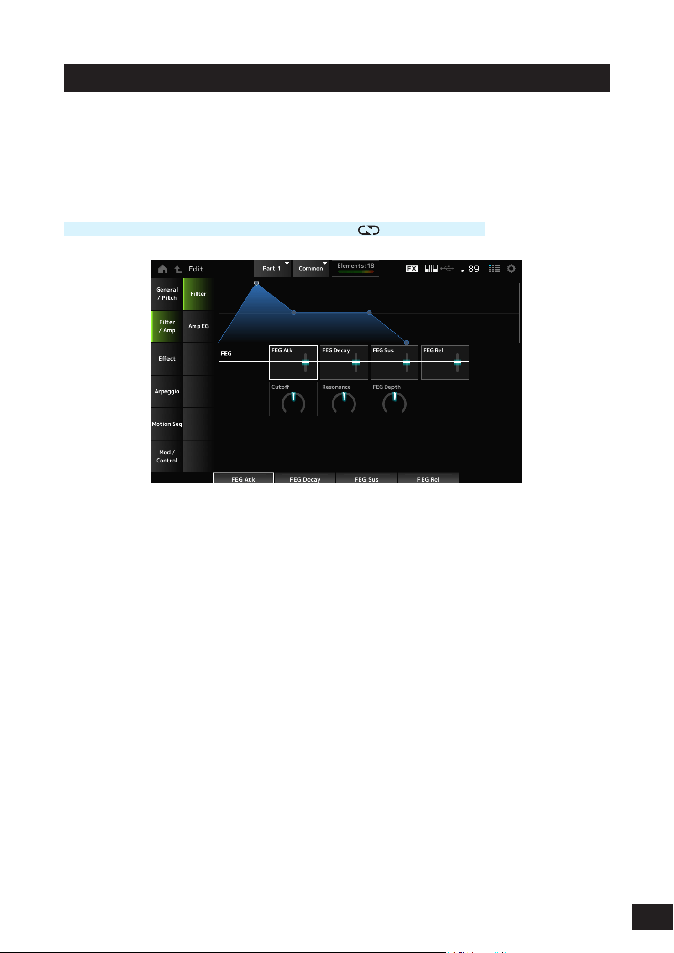
204
MODX M Operation Manual
Filter/Amp
Filter
On the Filter screen, you can set the Filter Envelope Generator (FEG) for the Part.
The FEG lets you set the degree (or level) of changes to the Cutoff Frequency and how those changes evolve over time,
starting from the moment you press a key on the keyboard to the moment the sound decays.
Operation
[PERFORMANCE (HOME)]
→
Part Common selection
→
[EDIT/ ]
→
Filter/Amp
→
Filter
FEG Atk (FEG Attack Time)
Sets the length of time it takes for the sound to change from the moment you press a key to when the Cutoff Frequency
reaches the value set at Attack Level (FEG Attack Level).
This is specied as an offset value to the Element FEG.
Settings: −64–+0–+63
FEG Decay (FEG Decay Time)
Sets the length of time it takes for the Cutoff Frequency to change from the Attack Level (FEG Attack Level). You can
control the crispness or the decay speed of the sound.
This is specied as an offset value to the Element FEG.
Settings: −64–+0–+63
FEG Sus (FEG Sustain Level)
Sets the Cutoff Frequency level that follows the end of the FEG Decay (FEG Decay Time).
This is specied as an offset value to the Element FEG.
Settings: −64–+0–+63
FEG Rel (FEG Release Time)
Sets the length of time it takes for the Cutoff Frequency to fall to the Release Level (FEG Release Level) when you lift your
nger from the key.
This is specied as an offset value to the Element FEG.
Settings: −64–+0–+63

205
MODX M Operation Manual
Cutoff (Filter Cutoff Frequency)
Changes the sound by setting the cutoff frequency of the lter. When the Low Pass Filter is selected, larger values here
result in a brighter sound, and smaller values result in a darker sound.
This is specied as an offset value to the cutoff frequency for the Element.
Settings: −64–+0–+63
Resonance (Filter Resonance)
Adds special characteristics to the sound by adjusting the signal level near the cutoff frequency.
This is specied as an offset value to the Resonance (Filter Resonance) or Width (Filter Width).
Settings: −64–+0–+63
FEG Depth
Adjusts the depth range of the cutoff frequency controlled by the FEG for the Element.
When it is set to 0, the settings in the Element will be used with no change.
Settings: −64–+0–+63
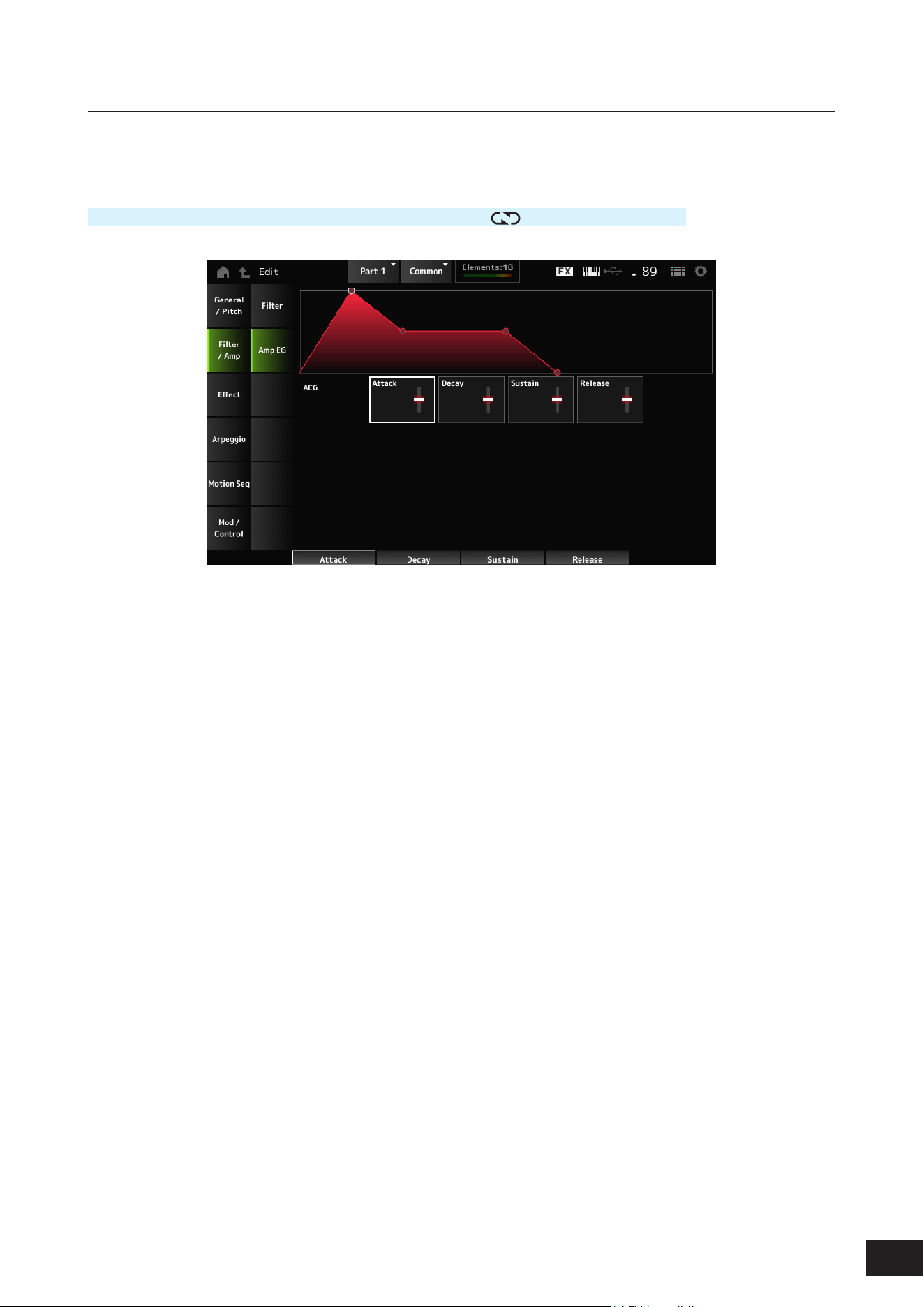
206
MODX M Operation Manual
Amp EG
On the Amp EG screen, you can set the AEG (Amplitude Envelope Generator) for the Part. By setting the Amp EG, you
can set how the volume changes from the moment you press a key on the keyboard to when the sound decays.
Operation
[PERFORMANCE (HOME)]
→
Part Common selection
→
[EDIT/ ]
→
Filter/Amp
→
Amp EG
AEG Attack (AEG Attack Time)
Sets the length of time it takes for the volume to change from the moment you press a key on the keyboard to when it
reaches the maximum.
This is specied as an offset value to the Element AEG.
Settings: −64–+0–+63
AEG Decay (AEG Decay Time)
Sets the length of time it takes for the volume to change after it has reached the maximum.
This is specied as an offset value to the Element AEG.
Settings: −64–+0–+63
AEG Sustain (AEG Sustain Level)
Adjusts the volume that is maintained after the AEG Decay (AEG Decay Time).
Settings: −64–+0–+63
AEG Release (AEG Release Time)
Sets the length of time it takes for the sound to decay after you have released the key.
This is specied as an offset value to the Element AEG.
Settings: −64–+0–+63
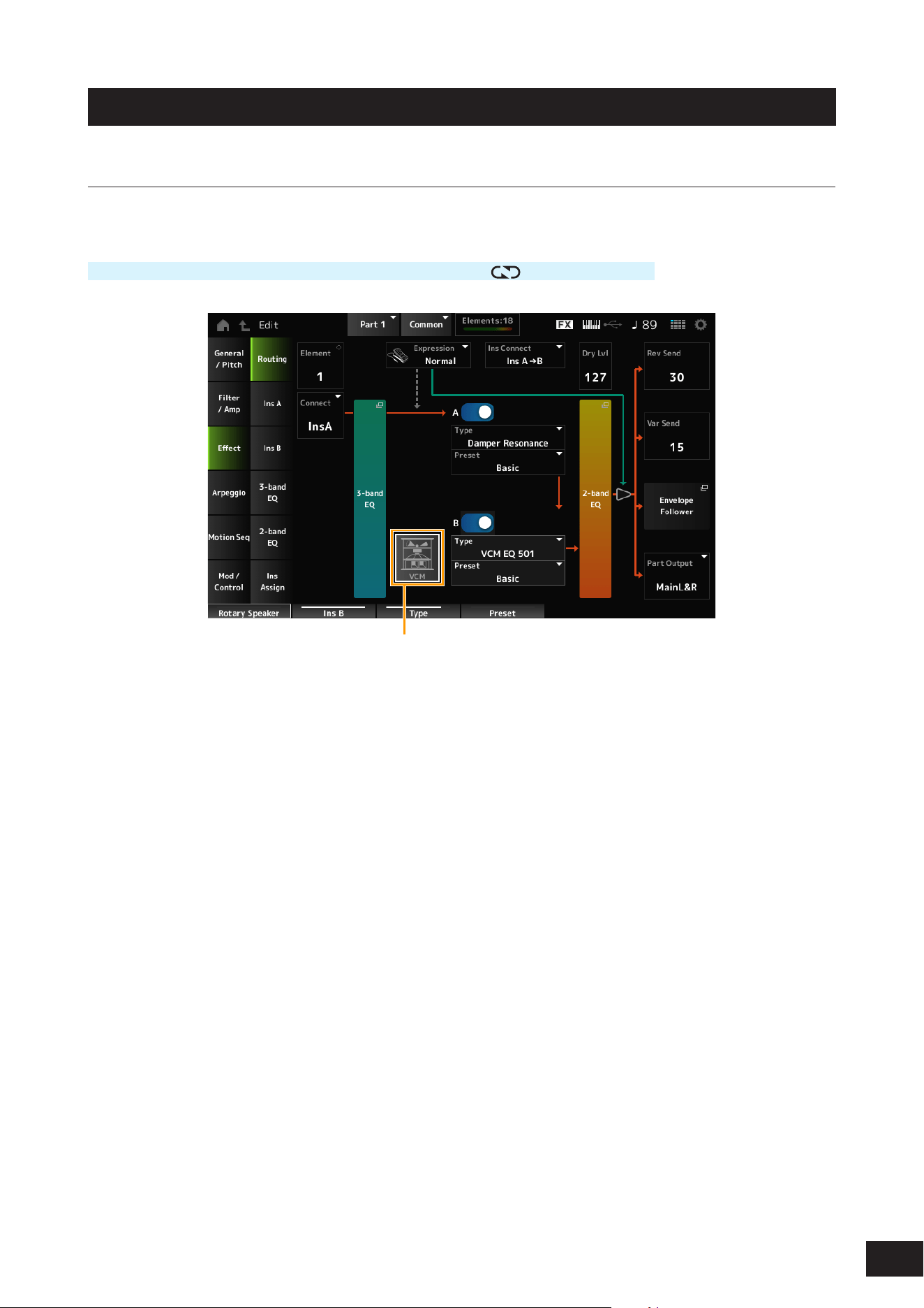
207
MODX M Operation Manual
Effect
Routing
On the Routing screen, you can set the effect routing for the Part.
Operation
[PERFORMANCE (HOME)]
→
Part Common selection
→
[EDIT/ ]
→
Effect
→
Routing
(1)
(1) VCM Rotary Speaker Switch
Element (Element Select)
Shows the name of the selected Element.
When Ex Elem Sw (General/Pitch
→
Element Settings) is set to Off, or when there are less than eight elements, the
numbers 1 to 8 are shown.
Settings: 1–128 (up to the Element Count setting)
Connect (Element Connection Switch)
Sets the Element to be output to Insertion Effect A or Insertion Effect B.
Setting this to Thru bypasses the Insertion Effects.
Settings: Thru, InsA, InsB
3-band EQ
Opens the setting screen for the 3-band EQ.

208
MODX M Operation Manual
Expression (Expression Type)
Sets the position in the signal ow when using the Expression pedal.
Settings: Normal, Pre FX
Normal: Applied after the 2-band EQ
Pre FX: Applied before the Insertion Effects. This setting is effective when used with non-linear (the sound changing
signicantly with the input level) effects such as Distortion
Exp. Curve (Expression Curve)
Sets the way the expression effect is applied with Exp. Curve when Expression Type is set to Pre FX.
Settings: Normal, Organ
Normal: Volume curve of normal characteristics
Organ: Volume curve of the characteristics simulating a vintage organ
VCM Rotary Speaker Switch
Sets the VCM Rotary Speaker effect, which simulates the characteristics of a rotary speaker by utilizing VCM technology.
This parameter is available only when the VCM Rotary Speaker Switch is set to Part 1.
Settings: Off, On
Ins Connect (Insertion Connection Type)
Sets the effect routing for Insertion Effect A and Insertion Effect B. The diagram changes accordingly when the settings
are changed.
Settings: Parallel, Ins A
→
B, Ins B
→
A
Parallel: (for Normal Part (AWM2) and Drum Part): The output from Insertion Effect A and Insertion Effect B are individually
sent to the Master Effect, Master EQ, Reverb, Variation, and Envelope Follower
Ins A
→
B: The output from Insertion Effect A is sent to Insertion Effect B, and the output from Insertion Effect B is sent to the
Master Effect, Master EQ, Reverb, Variation, and Envelope Follower.
Ins B
→
A: The output from Insertion Effect B is sent to Insertion Effect A, and the output from Insertion Effect A is sent to the
Master Effect, Master EQ, Reverb, Variation, and Envelope Follower.
Parallel Ins A
→
B Ins B
→
A
A
B
A
B
A
B
A (Insertion Effect A Switch)
B (Insertion Effect B Switch)
Turns Insertion Effect A or B on or off.
Settings: Off, On
Type (Insertion Effect Type)
Sets the Effect Type.
Settings: Refer to the Effect types
Preset (Insertion Effect Preset)
Selects one of the Preset effect parameters for each Effect Type.
By selecting a Preset, you can change the way effects are applied.
Settings: Refer to the Data List

209
MODX M Operation Manual
Side Chain (Insertion Side Chain Part)
Modulator (Insertion Modulator Part)
Sets the Side Chain Part (or the Modulator depending on the effect type) for the Insertion Effect A or Insertion Effect B.
This parameter is not available when the Part itself or Master is set to the Modulator. In that case, the parameter value will
be shown in parenthesis as in "(Master)."
Settings: Part 1–16, A/D, Master, Off
Dry Level
Sets the dry level (or the level of the signals not processed by the System Effect) of the selected Part.
This parameter is available only when Part Output (Part Output Select) is set to MainL&R.
Settings: 0–127
2-band EQ
Opens the setting screen for the 2-band EQ.
Rev Send (Reverb Send)
Sets the level of the signals (or bypass signals) sent from Insertion Effect A or Insertion Effect B to the Reverb Effect. This
parameter is available only when Part Output (Part Output Select) is set to MainL&R.
Settings: 0–127
Var Send (Variation Send)
Sets the level of the signals (or bypass signals) sent from Insertion Effect A or Insertion Effect B to the Variation Effect.
This parameter is available only when Part Output (Part Output Select) is set to MainL&R.
Settings: 0–127
Envelope Follower
Opens the settings screen for the Envelope Follower.
Part Output (Part Output Select)
Sets the output destination for the audio signals.
Settings: MainL&R, (AsgnL&R), USB Stereo, (AsgnL), (AsgnR), USB mono, Off
MainL&R: Outputs in stereo (two channels) to the OUTPUT [L/MONO] and OUTPUT [R] jacks.
USB Stereo: Outputs in stereo (channels 1 and 2, to channels 7 and 8) to the USB [TO HOST] terminal
USB mono: Outputs in mono (channels 1 to 8) to the USB [TO HOST] terminal
Off: No output of the audio signal for the Part.
NOTE
The settings for data compatibility with MONTAGE M are shown below. They are considered Off when set.
• AsgnL&R
• USB Stereo: USB9&10 – USB29&30
• USB mono: USB9 – USB30
• AsgnL
• AsgnR
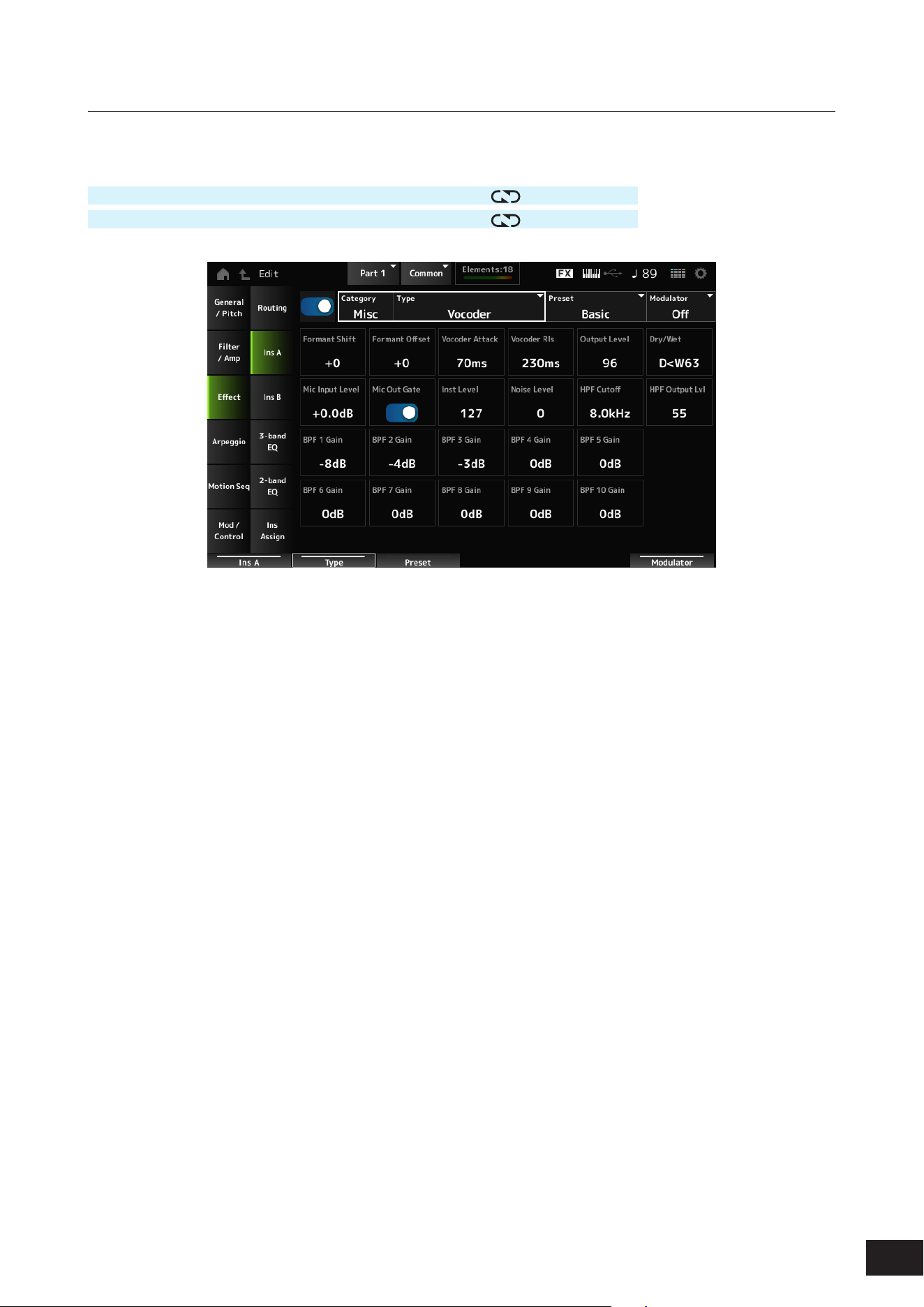
210
MODX M Operation Manual
Ins A, Ins B
On the Ins A and Ins B screens, you can set the Insertion Effects.
Operation
[PERFORMANCE (HOME)]
→
Part Common selection
→
[EDIT/ ]
→
Effect
→
Ins A
[PERFORMANCE (HOME)]
→
Part Common selection
→
[EDIT/
]
→
Effect
→
Ins B
The same as Audio In
→
Ins A and Ins B on the Common Edit screen.
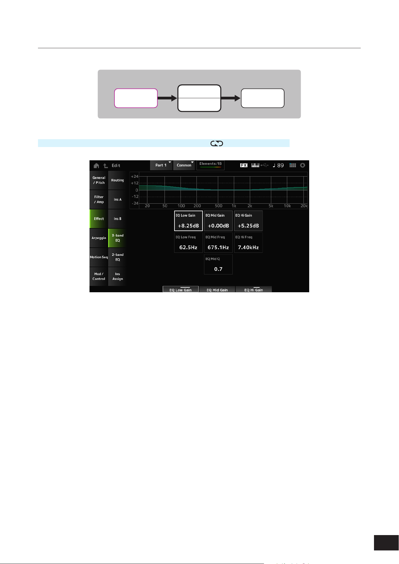
211
MODX M Operation Manual
3-band EQ
On the 3-band EQ screen, you can set the Part EQ. EQ can be set before the Insertion Effect.
Part EQ
Part EQ
3-band EQ
Insertion A
Insertion B
2-band EQ
Part
Operation
PERFORMANCE (HOME)]
→
Part Common selection
→
[EDIT/ ]
→
Effect
→
3-band EQ
EQ Low Gain (3band EQ Low Gain)
Sets the signal level of the Low band.
Settings: −12.00dB – +0.00dB – +12.00dB
EQ Low Freq (3band EQ Low Frequency)
Sets the frequency of the Low band.
Settings: 50.1Hz–2.00kHz
EQ Mid Gain (3band EQ Mid Gain)
Sets the signal level of the Mid band.
Settings: −12.00dB – +0.00dB – +12.00dB
EQ Mid Freq (3band EQ Mid Frequency)
Sets the frequency of the Mid band.
Settings: 139.7Hz–10.1kHz
EQ Mid Q (3band EQ Mid Q)
Sets the bandwidth of the Mid band.
Settings: 0.7–10.3
EQ Hi Gain (3band EQ High Gain)
Sets the signal level of the High band.
Settings: −12.00dB – +0.00dB – +12.00dB
EQ Hi Freq (3band EQ High Frequency)
Sets the frequency of the High band.
Settings: 503.8Hz–14.0kHz
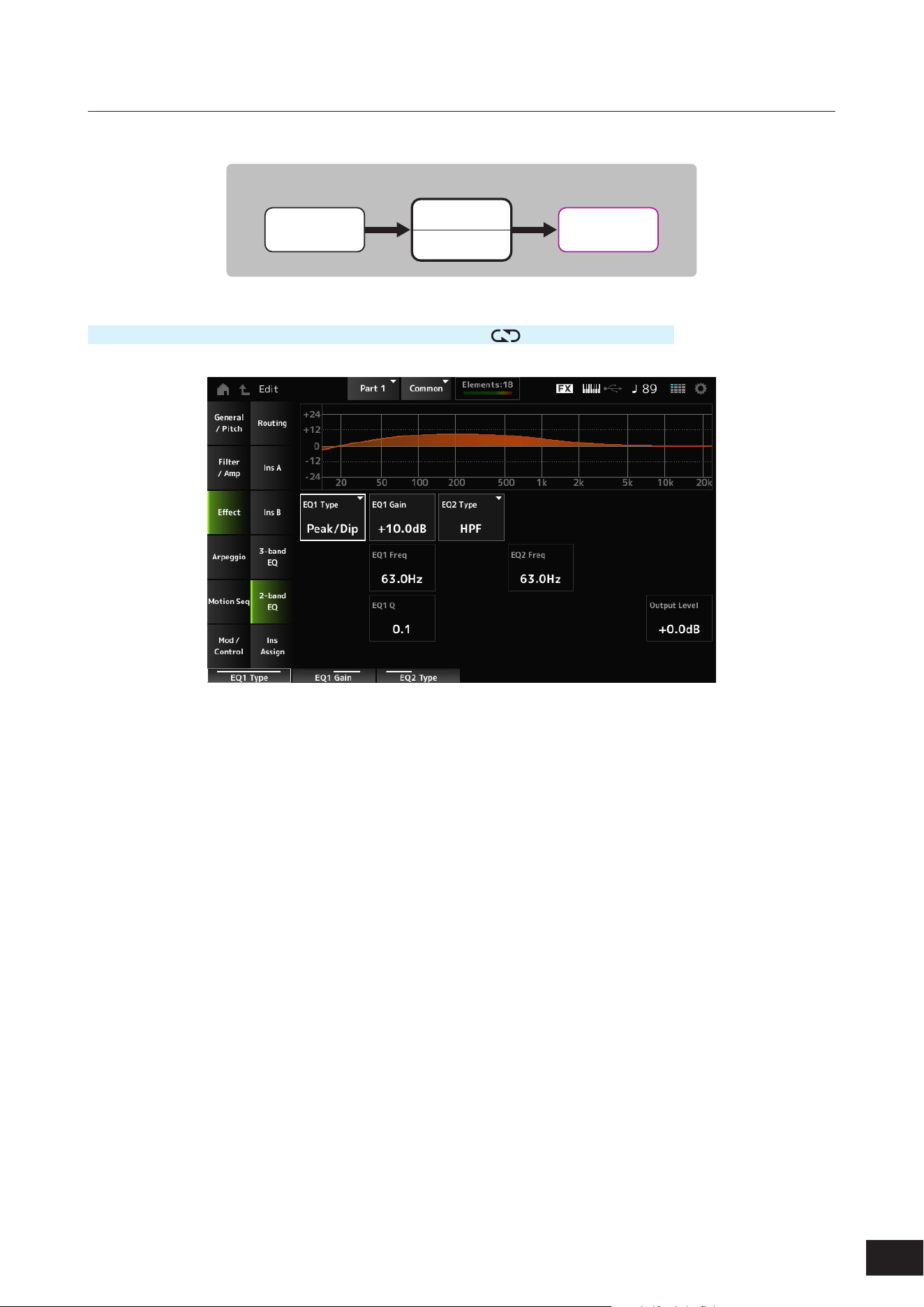
212
MODX M Operation Manual
2-band EQ
On the 2-band EQ screen, you can set the Part EQ. EQ can be set after the Insertion Effect.
Part EQ
Part EQ
3-band EQ
Insertion A
Insertion B
2-band EQ
Part
Operation
[PERFORMANCE (HOME)]
→
Part Common selection
→
[EDIT/ ]
→
Effect
→
2-band EQ
EQ1 Type (2band EQ 1 Type)
EQ2 Type (2band EQ 2 Type)
Selects the desired EQ type.
Settings: Thru, LPF, HPF, Low Shelf, Hi Shelf, Peak/Dip
Thru: Passes the signals with no effects being applied.
LPF: Cuts the signals above the cutoff frequency.
HPF: Cuts the signals below the cutoff frequency.
Low Shelf: Cuts or boosts the signals below the specied frequency setting.
Hi Shelf: Cuts or boosts the signals above the specied frequency setting.
Peak/Dip: Cuts or boosts the signals at the specied frequency setting.
EQ 1 Gain (2band EQ 1 Gain)
EQ 2 Gain (2band EQ 2 Gain)
Sets the signal level of the frequency band set in EQ1 Type (2band EQ 1 Type) or EQ2 Type (2band EQ 2 Type). This
parameter is not available when the EQ Type is set to Thru, LPF, or HPF.
Settings: −12.0dB – +0.0dB – +12.0dB
EQ 1 Freq (2band EQ 1 Frequency)
EQ 2 Freq (2band EQ 2 Frequency)
Sets the frequency to be cut or boosted. This parameter is not available when the EQ Type is set to Thru.
Settings: 63.0Hz–18.0Hz
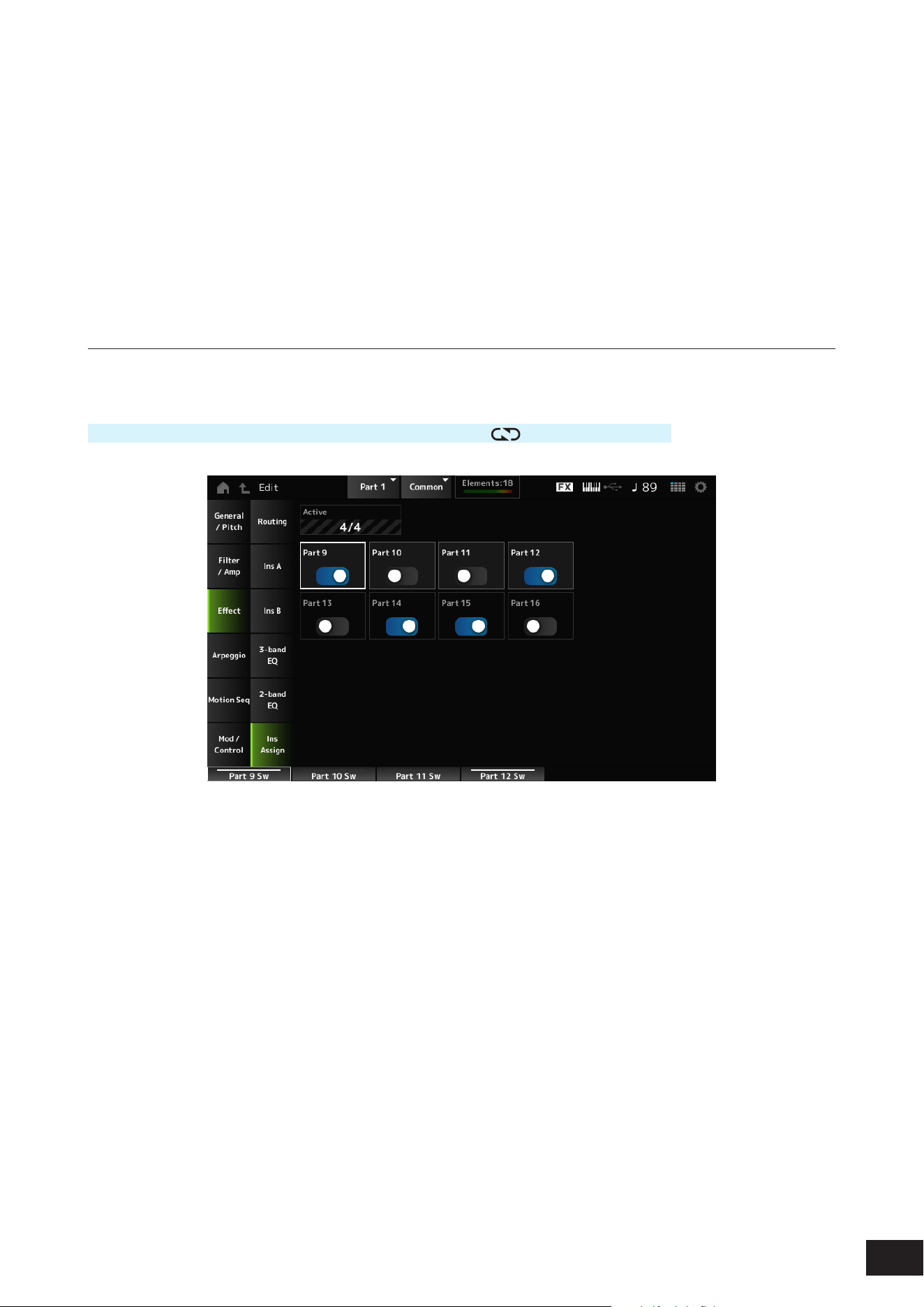
213
MODX M Operation Manual
EQ 1 Q (2band EQ 1 Q)
EQ 2 Q (2band EQ 2 Q)
Sets the bandwidth for cutting or boosting the volume of the frequencies set with EQ1 Type (2band EQ 1 Type) or EQ2
Type (2band EQ 2 Type). This parameter is available only when the EQ Type is set to Peak/Dip.
Settings: 0.1–12.0
Output Level (2band EQ Output Level)
Sets the output gain of the 2-band EQ.
Settings: −12.0dB – +0.0dB – +12.0dB
Ins Assign
On the Ins Assign screen, you can enable the Part 9 to 16 Insertion Effect.
Operation
[PERFORMANCE (HOME)]
→
Part Common selection
→
[EDIT/ ]
→
Effect
→
Ins Assign
Active (Active Part)
This shows the number of Parts whose Insertion Effect switch is set to On. The number to the right of the slash (/) is the
maximum number of Insertion Effects that can be turned On simultaneously.
Part 9–16
Enables the Insertion Effect for Parts 9 to 16.
Settings: Off, On
NOTE
The Insertion Effect is always enabled for Parts 1 to 8.
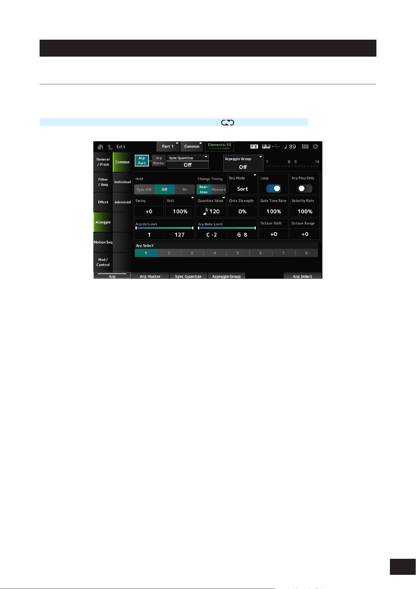
214
MODX M Operation Manual
Arpeggio
Common
On the Common screen, you can set the Arpeggio for the entire Part.
Operation
[PERFORMANCE (HOME)]
→
Part Common selection
→
[EDIT/ ]
→
Arpeggio
→
Common
Arp Part (Part Arpeggio Switch)
Sets the Arpeggio for the Part on or off.
Settings: Off, On
Arp Master (Arpeggio Master Switch)
Sets the Arpeggio for the Performance on or off.
Settings: Off, On
Sync Quantize (Arpeggio Sync Quantize Value)
Adjusts the timing for starting the next Arpeggio phrase while the rst Arpeggio is being played back, when playing back
Arpeggio phrases in multiple Parts.
When set to Off, the Arpeggio is played back when you play the Part on the keyboard.
The value shown here is in clocks.
Settings: Off, 60 (thirty-second note), 80 (sixteenth note triplet), 120 (sixteenth note), 160 (eighth note triplet), 240 (eighth note), 320
(quarter note triplet), 480 (quarter note)
Arpeggio Group
Sets the Arpeggio Group for using the same Arpeggio on multiple Parts.
Indicator
This Indicator is set to On for the Part that is in the same Arpeggio Group as the selected Part.

215
MODX M Operation Manual
Hold (Arpeggio Hold)
Enables or disables the Hold function, which continues to repeatedly play back the Arpeggio even after you lift your nger.
Settings: Sync-Off, Off, On
Sync-Off: Repeats Arpeggio playback in the background while your ngers release the keys and resumes playback when
you press any key on the keyboard
Off: Plays back the Arpeggio only while any key is being held
On: When you press a key, the Arpeggio will repeat even after you lift your nger
Change Timing (Arpeggio Change Timing)
Sets the timing for changing the Arpeggio type while another Arpeggio phrase is still being played back. You can select
Real-time for switching to a new Arpeggio phrase immediately or Measure for switching to a new Arpeggio phrase at the
top of the next measure.
Settings: Real-time, Measure
Key Mode (Arpeggio Key Mode)
Sets the way Arpeggio is played back.
Settings: Sort, Thru, Direct, Sort+Drct, Thru+Drct
Sort: Plays back the same Arpeggio regardless of the order of keys played
Thru: Plays back the Arpeggio differently depending on the order of keys played
Direct: Does not play back the Arpeggio. Only your keyboard performance will be played. However, if the Arpeggio data
includes Control Change (CC) data such as Pan or Brightness, these effects be reected. This is effective when the Arpeggio
type includes Control Change data or when an Arpeggio in the Control category is selected
Sort+Drct: Plays back the Arpeggio according to the Sort setting, as well as the notes played on the keyboard
Thru+Drct: Plays back the Arpeggio according to the Thru setting, as well as the notes played on the keyboard
Loop (Arpeggio Loop)
Selects loop (repeat) playback while holding the key on the keyboard, or one-shot playback for the Arpeggio every time
you press a key.
Settings: Off, On
Arp Play Only (Arpeggio Play Only)
Sets the Part to be played only with the Arpeggio.
The Part set to On will be played by Note On messages sent for the Arpeggio.
Settings: Off, On
Swing
Changes the timing of even-numbered beats (backbeats) counted from the value specied in Quantize Value to add a
swing feel to the Arpeggio playback. This setting is useful for creating desired rhythms for playing swing, shuffle, and
bounce feels.
Settings: −120–+0 –+120
+1 and higher: Moved behind the beat
-1 and lower: Moved ahead of the beat
0: Does not change the even-numbered beats or add any swing feel
Unit (Arpeggio Unit Multiply)
Sets the percentage for stretching or compressing the Arpeggio playback time.
The subdivision of the beat and the tempo will change when you stretch or compress the playback time, so you can create
a completely new feel for the originally selected Arpeggio.
Settings: 50%, 66%, 75%, 100%, 133%, 150%, 200%, 266%, 300%, 400%, Common
200%: The playback time is doubled, and the tempo is halved
100%: The playback time is kept unchanged
50%: The playback time is halved, and the tempo is doubled
Common: The value set in the Unit common to all Parts is applied

216
MODX M Operation Manual
Quantize Value (Arpeggio Quantize Value)
Sets the reference note for using quantize and swing. The value shown here is in clocks.
Settings: Off, 60 (thirty-second note), 80 (sixteenth note triplet), 120 (sixteenth note), 160 (eighth note triplet), 240 (eighth note),
320(quarter note triplet), 480 (quarter note)
Qntz Strength (Arpeggio Quantize Strength)
Sets the strength of the Quantize Value (Arpeggio Quantize Value) setting (or how close the notes are to the reference
note set in Quantize Value). A setting of 100% shifts the timing completely to that set in Quantize Value, while a setting of
0% results in no quantization.
Settings: 0%–100%
Gate Time Rate (Arpeggio Gate Time Rate)
Sets the Gate Time (or time length for playing the notes) for Arpeggio playback. If the Gate Time is set to a value of 0 as
a result, the setting will be changed to a value of 1.
Settings: 0%–200%
Velocity Rate (Arpeggio Velocity Rate)
Sets the velocity rate of the Arpeggio playback. If the Velocity is set to the value of 0 as a result, the setting will be
changed to a value of 1. When it is set to a value larger than 128, the setting will be changed to a value of 127.
Settings: 0%–200%
Arp Vel Limit (Arpeggio Velocity Limit)
Sets the velocity range (lowest and highest values) for Arpeggio playback.
When this is set so that the higher value is rst and the lower value is second (for example, 93 to 34), the Arpeggio is
played only for velocities of 1 to 34 and 93 to 127.
Settings: 1–127
Arp Note Limit (Arpeggio Note Limit)
Sets the note range (the lowest and the highest notes) for Arpeggio playback.
When the rst note specied is higher than the second (for example, C5 to C4), the notes in the ranges C−2 to C4 and C5
to G8 will be played.
Settings: C−2–G8
Octave Shift (Arpeggio Output Octave Shift)
Shifts the pitch of the Arpeggio in octaves.
Settings: −10–+0–+10
Octave Range (Arpeggio Octave Range)
Shifts the range of the Arpeggio in octaves.
Settings: −3–+0–+3
Arp Select (Arpeggio Select)
Selects the Arpeggio.
Settings: 1–8

217
MODX M Operation Manual
Individual
On the Individual screen, you can set the Arpeggio type parameters for Arp Select (Arpeggio Select) 1–8.
Tapping the Arpeggio Type setting calls up the context menu. Selecting Category Search opens the Arpeggio Category
Search screen. Selecting Number allows you to specify the Arpeggio Type by number.
Operation
[PERFORMANCE (HOME)]
→
Part Common selection
→
[EDIT/ ]
→
Arpeggio
→
Individual
(When a selected Part is something other than Common) [SHIFT] + [ARP]
Arp Part (Part Arpeggio Switch)
Arp Master (Arpeggio Master Switch)
Sync Quantize (Arpeggio Sync Quantize Value)
Arpeggio Group
Indicator
The same as the Common screen.
Arp (Arpeggio Select)
Switches the Arpeggio Select.
Settings: 1–8
Category (Arpeggio Category)
Shows the Category of the selected Arpeggio.
Settings: Refer to the Data List
Sub (Arpeggio Sub Category)
Shows the Sub category of the selected Arpeggio.
Settings: Refer to the Data List
Name (Arpeggio Name)
Shows the name of the selected Arpeggio.
Settings: Refer to the Data List
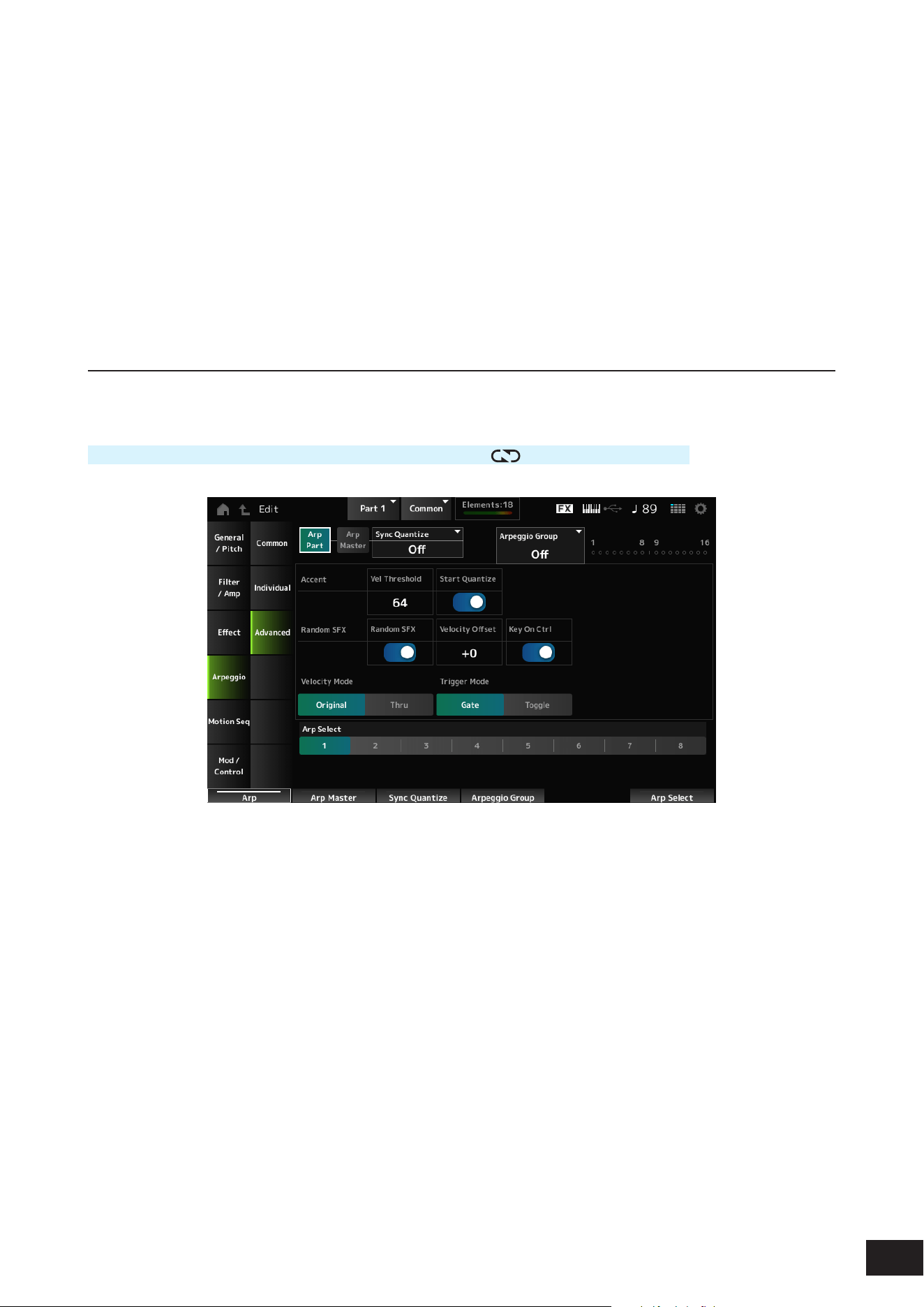
218
MODX M Operation Manual
Velocity (Arpeggio Velocity Rate)
Sets the velocity rate of the Arpeggio playback.
If the Velocity is set to the value of 0 as a result, the setting will be changed to a value of 1. When it is set to a value larger
than 128, the setting will be changed to a value of 127.
Settings: −100%–+0%–+100%
Gate Time (Arpeggio Gate Time Rate)
Sets the Gate Time (or time length for playing the notes) for Arpeggio playback.
If the Gate Time is set to a value of 0 as a result, the setting will be changed to a value of 1.
Settings: −100%–+0%–+100%
Advanced
On the Advanced screen, you can set the Arpeggio parameters.
Operation
[PERFORMANCE (HOME)]
→
Part Common selection
→
[EDIT/ ]
→
Arpeggio
→
Advanced
Arp Part (Part Arpeggio Switch)
Arp Master (Arpeggio Master Switch)
Sync Quantize (Arpeggio Sync Quantize Value)
Arpeggio Group
Indicator
The same as the Common screen.
Accent Vel Threshold (Arpeggio Accent Velocity Threshold)
Sets the velocity level for triggering an Accent Phrase. Accent Phrases are sequence phrases that have been
programmed to certain types of Arpeggio patterns to be played back only when the keys are played at a fast velocity.
When you press a key at a velocity greater than the set value, the Accent Phrase will be played back. If you press a key
but it the Accent Phrase doesn't play back, try setting it a little lower and then pressing the key again.
Settings: Off, 1–127
NOTE
For more information on the Arpeggio types that support Accent Phrases, refer to the Data List.

219
MODX M Operation Manual
Accent Start Quantize (Arpeggio Accent Start Quantize)
Sets the Accent Phrase to be triggered when a key is pressed at the velocity value larger than the Accent Vel Threshold
(Arpeggio Accent Velocity Threshold) (set to On) or triggered at the timing set in the selected Arpeggio type (set to Off).
Settings: Off, On
Random SFX (Arpeggio Random SFX)
Enables the Random SFX function.
The Random SFX function triggers special sounds included in some Arpeggio types. There are various types of special
sounds you can use according to the Arpeggio Type. For example, you can use this function to add guitar fret noises when
you release your nger from the key.
Settings: Off, On
NOTE
For more information on the Arpeggio types that support this function, refer to the Data List.
Random SFX Velocity Offset (Arpeggio Random SFX Velocity Offset)
Sets the velocity value for triggering special sounds for the Random SFX function.
Settings: −64–+0–+63
Random SFX Key On Ctrl (Arpeggio Random SFX Key On Control)
Sets special sounds to be triggered by the velocity level for pressing keys or by the velocity level automatically set.
Settings: Off, On
Velocity Mode (Arpeggio Velocity Mode)
Sets the velocity for playing back the Arpeggio.
Settings: Original, Thru
Original: Follows the velocity level set in the Arpeggio Type.
Thru: Follows the velocity level of the keystroke
Trigger Mode (Arpeggio Trigger Mode)
Switches the Arpeggio playback method.
Settings: Gate, Toggle
Gate: Starts the Arpeggio playback by pressing a key, and stops it by releasing the key
Toggle: Alternates starting and stopping the Arpeggio playback by pressing a key
Arp Select (Arpeggio Select)
Switches the Arpeggio Select.
Settings: 1–8
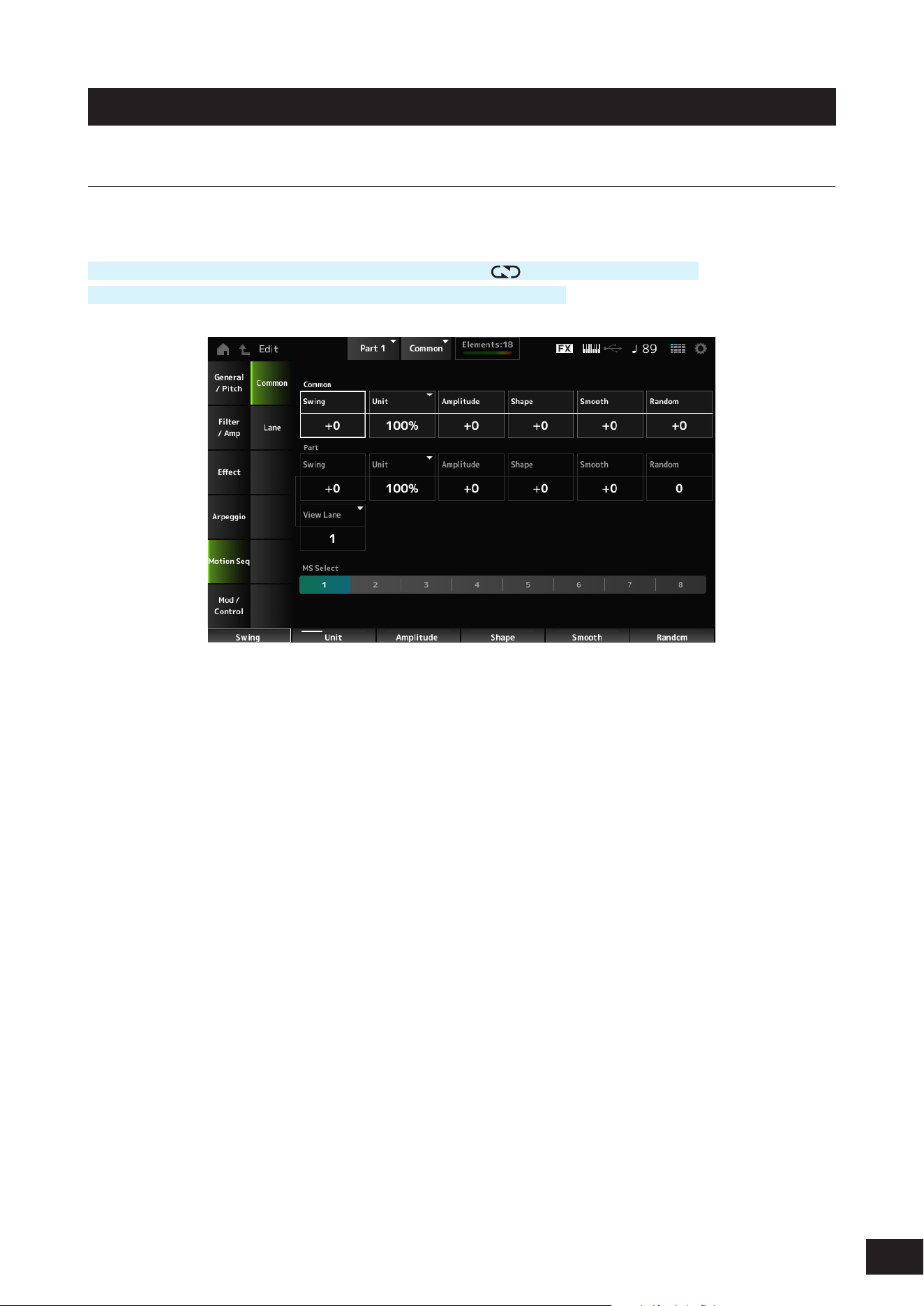
220
MODX M Operation Manual
Motion Seq
Common
On the Common screen, you can set the Motion Sequencer parameters for the entire Part.
Operation
[PERFORMANCE (HOME)]
→
Part Common selection
→
[EDIT/ ]
→
Motion Seq
→
Common
(When a selected Part is something other than Common) [SHIFT] + [MSEQ]
Common Swing (Common Swing Offset)
Sets the swing value of the Arpeggio and Motion Sequencer for the Performance.
This is specied as an offset value to the Part Swing.
Settings: −120 –+0–+120
Common Unit (Common Unit Multiply)
Sets the percentage for stretching or compressing the Arpeggio and Motion Sequencer playback time for the entire
Performance.
This parameter affects Lanes for which Unit (Lane Unit Multiply) is set to Common.
The subdivision of the beat and the tempo will change when you stretch or compress playback time, so you can create a
completely new feel for the Motion Sequence you have originally selected.
Settings: 50%–400%
200%: The playback time is doubled, and the tempo is halved
100%: The playback time is kept unchanged
50%: The playback time is halved, and the tempo is doubled
Common Amplitude (Common Motion Sequencer Amplitude Performance Offset)
Sets the Motion Sequencer Amplitude (or how much the Sequence changes) for the entire Performance.
This parameter value offsets the Amplitude of the Lanes within the Part if MS FX (Lane FX Receive) is set to On.
This is specied as an offset value to the Part Amplitude (Part Motion Sequencer Amplitude) of each Part.
Settings: −127–+0–+127

221
MODX M Operation Manual
Common Shape (Common Motion Sequencer Pulse Shape Performance Offset)
Sets the Motion Sequencer Pulse Shape (or the shape of the step curve) for the Performance.
This parameter value offsets the parameters for the Lanes within the Part if MS FX (Lane FX Receive) is set to On for the
lane and Control (Motion Sequence Step Curve Shape Control Switch) is set to On.
This is specied as an offset value to the Part Shape (Part Motion Sequencer Pulse Shape) of each Part.
Settings: −100–+0–+100
Common Smooth (Common Motion Sequencer Smoothness Performance Offset)
Sets the Motion Sequence Smoothness (or the smoothness of the changes in the sequence over time) for the entire
Performance.
This parameter value offsets the Smoothness of the Lanes within the Part if MS FX (Lane FX Receive) is set to On for the
Lane.
This is specied as an offset value to the Part Motion Seq Smooth (Part Motion Sequencer Smoothness) of each Part.
Settings: −127–+0–+127
Common Random (Common Motion Sequencer Randomness Performance Offset)
Sets the Motion Sequencer Randomness (or the randomness of the changes in the step value of the sequence) for the
entire Performance.
This parameter value offsets the Randomness of the Lanes within the Performance if MS FX (Lane FX Receive) is set to
On for the Lane.
This is specied as an offset value to the Part Motion Seq Random (Part Motion Sequencer Randomness) of each Part.
Settings: −127–+0–+127
Part Swing (Part Swing)
Changes the timing of the even-numbered beats (backbeats) counted from the value specied in MS Grid to add a swing
feel to the Motion Sequencer playback. This setting is useful for creating desired rhythms for playing swing, shuffle, and
bounce feels.
Settings: −120–+0 –+120
+1 and higher: Moved behind the beat
0: Does not change the even-numbered beats or add any swing feel
-1 and lower: Moved ahead of the beat
Part Unit (Arpeggio Unit Multiply)
Sets the percentage for stretching or compressing the Arpeggio playback time for the Part.
The parameter setting is effective when the Unit (Lane Unit Multiply) of each Lane is set to Arp.
Settings: 50%–400%, Common
200%: The playback time is doubled, and the tempo is halved
100%: The playback time is kept unchanged
50%: The playback time is halved, and the tempo is doubled
Common: The value set in the Unit common to all Parts is applied
Part Amplitude (Part Motion Sequencer Amplitude)
Sets the Motion Sequencer Amplitude (or how much the Sequence changes) for the Part. This parameter value offsets
the Amplitude of the Lanes within the Part if the MS FX (Lane FX Receive) is set to On for the lane.
This is specied as an offset value to the Amplitude (Motion Sequence Amplitude) for each Lane.
Settings: −127–+0–+127
Part Shape (Part Motion Sequencer Pulse Shape)
Sets the Motion Sequencer Pulse Shape (or the shape of the step curve) for the Part. This parameter value offsets
the parameters for the Lanes within the Part if MS FX (Lane FX Receive) is set to On for the lane and Control (Motion
Sequence Step Curve Shape Control Switch) is set to On.
This is specied as an offset value to the Prm (Motion Sequence Step Curve Parameter) for each Lane.
Settings: −100–+0–+100

222
MODX M Operation Manual
Part Smooth (Part Motion Sequencer Smoothness)
Sets the Motion Sequencer Smoothness for the Part. This parameter value offsets the Smoothness of the Lanes within
the Part if MS FX (Lane FX Receive) is set to On for the Lane.
This is specied as an offset value to the Smooth (Motion Sequence Smoothness) for each Lane.
Settings: −127–+0–+127
Part Random (Part Motion Sequencer Randomness)
Sets the Motion Sequencer Randomness for the Part.
Sets randomness of the changes in the Step value of the sequence.
Settings: 0–127
View Lane
Sets the Lane to show when the View Mode of the Home screen is set to Motion Seq View.
MS Select (Motion Sequence Select)
Selects the Motion Sequence to playback.
Settings: 1–8
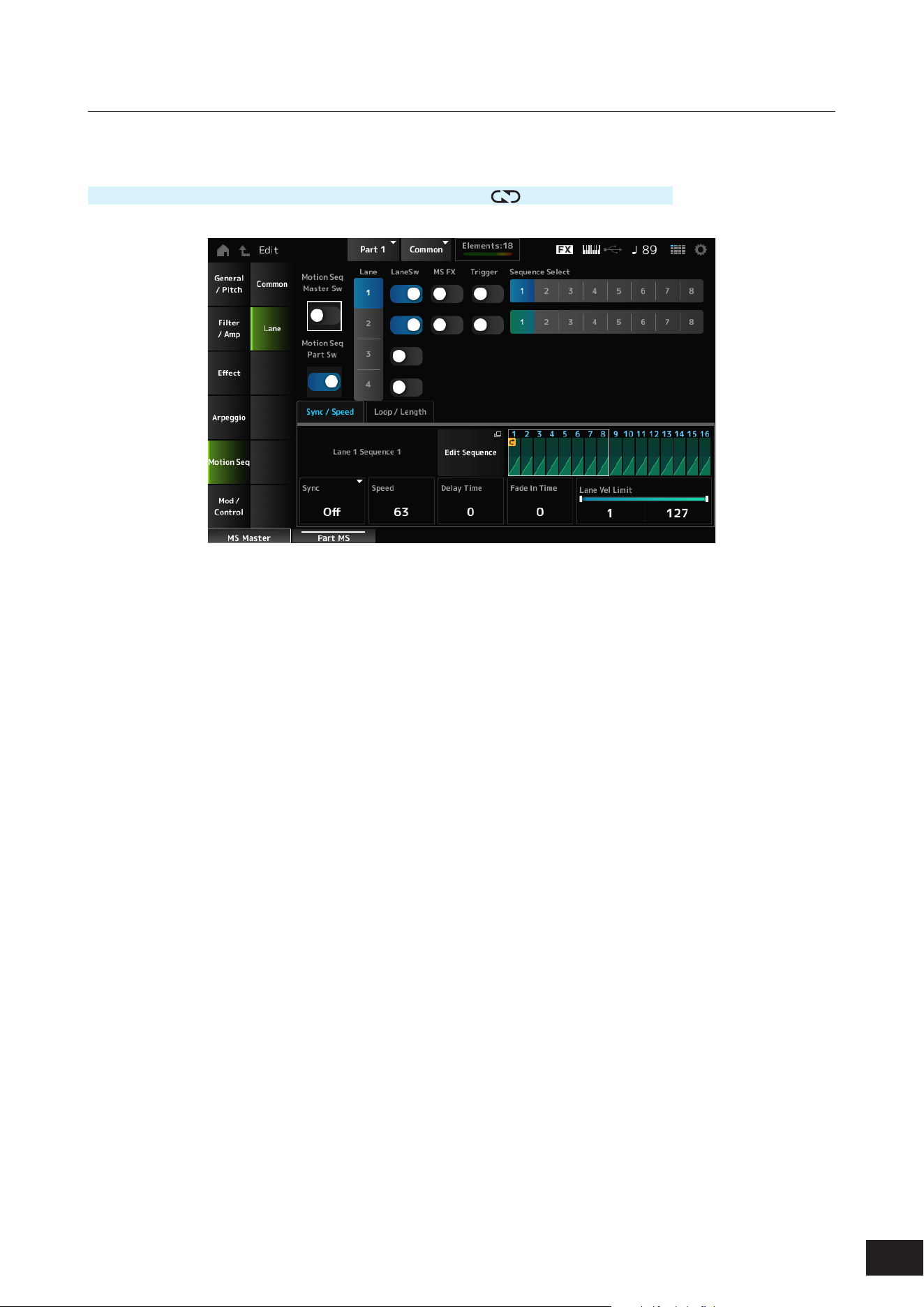
223
MODX M Operation Manual
Lane
On the Lane screen, you can set the parameters for each Motion Sequencer Lane.
Operation
[PERFORMANCE (HOME)]
→
Part Common selection
→
[EDIT/ ]
→
Motion Seq
→
Lane
Motion Seq Master Sw (Motion Sequencer Master Switch)
Sets the Motion Sequencer for the entire Performance on or off.
Settings: Off, On
Motion Seq Part Sw (Motion Sequencer Part Switch)
Sets the Motion Sequencer of the Part on or off.
Settings: Off, On
Lane Select
Selects a Lane.
Settings: 1–4
LaneSw (Lane Switch)
Sets each Lane on or off.
You can use up to four Motion Sequencer lanes in one Part, or up to eight lanes in an entire Performance.
When set to Off, the parameters for that lane will not be shown.
Settings: Off, On
MS FX (Lane FX Receive)
Sets the selected Lane to receive the signals from the knobs for changing the Motion Sequencer parameters.
Settings: Off, On
Trigger (Lane Trigger Receive)
Sets the selected Lane to receive the signals from the [MSEQ TRIGGER] button.
When set to On, the Motion Sequence will not be played back unless you press the [MSEQ TRIGGER] button.
Settings: Off, On

224
MODX M Operation Manual
Sequence Select (Motion Sequence Select)
Changes the Motion Sequence selection.
Settings: 1–8
Target Sequence
Indicates the Lane and the Sequence.
Edit Sequence
The Motion Sequence Edit screen will open.
You can create a sequence of up to 16 steps.
Motion Seq Step Value
Sets the value for each step in the Motion Sequence.
You can use Control sliders 1 to 8 to change the values for Steps 1 to 8 and Steps 9 to 16, depending on the cursor
position.
Settings: 0–127
Sync/Speed Tabs
Sync (Lane Sync)
Sets the playback of the Motion Sequence set to the Destination in the Control Assign screen to synchronize to the
Performance tempo, beat, or arpeggio.
Settings: Off, Tempo, Beat, Arp, Lane1 (when Lane2–4 are selected)
Off: Plays back the Lane Motion Sequencer alone
Tempo: Plays back the Lane Motion Sequencer at the Performance tempo.
Beat: Plays back in sync with the beat.
Arp: Plays back the Lane Motion Sequencer in sync with the top of the Arpeggio playback.
Lane1: Plays back the Lane Motion Sequencer in sync with Lane 1
• When Sync is set to Off
Speed (Lane Speed)
Sets the playback speed for the Motion Sequence.
This parameter is available when Sync (Lane Sync) is set to Off.
Settings: 0–127
Delay Time (Lane Key On Delay Time Length)
Sets the delay time for starting the playback of the Motion Sequence.
Settings: 0–127
Fade In Time (Lane Fade In Time Length)
Sets the time for the Motion Sequence to reach maximum amplitude.
Settings: 0–127

225
MODX M Operation Manual
• When Sync is set to something other than Off
Unit (Lane Unit Multiply)
Sets the percentage for stretching or compressing the Motion Sequencer playback time for the selected Lane.
This parameter is available when Sync (Lane Sync) is set to Tempo, Beat, or Arp.
Settings: 50%–6400%, Common, Arp
200%: The playback time is doubled, and the tempo is halved
100%: The playback time is kept unchanged
50%: The playback time is halved, and the tempo is doubled
Common: The value set in the Unit common to all Parts is applied
Arp: The value set in the Unit of the Part Arpeggio is applied
Delay Steps (Lane Key On Delay Step)
Sets the delay time for starting the playback of the Motion Sequence when Sync (Lane Sync) is set to Tempo, Beat, or
Arp.
Settings: 0–32
Fade In Steps (Lane Fade In Step Length)
Sets the time to reach the maximum amplitude for the Motion Sequence when Sync (Lane Sync) is set to Tempo, Beat,
Arp, or Lane1.
Settings: 0–32
Lane Vel Limit (Lane Velocity Limit)
Sets the velocity range (lowest and highest values) for playing back the Motion Sequence of the selected Lane.
This parameter is available when Sync (Lane Sync) is set to Off, Tempo, Beat, or Arp.
When the Velocity Limit is set to a range from the highest value to the lowest value, the Motion Sequence will be played
back in two velocity ranges: from the maximum to the highest value, and from the lowest value to the minimum.
Settings: 1–127
Loop/Length Tabs
Key On Reset (Lane Key On Reset)
Resets the Motion Sequence playback when you press any key on the keyboard.
This parameter is available when Sync (Lane Sync) is set to Off, Tempo, or Beat. This parameter is not available when
Trigger is set to On.
Settings: Off, Each-On, 1st-On
Each-On: Each time you play any note, the sequence will be reset and the playback starts from the beginning
1st-On: Playback starts from the beginning at the rst note you play. When the second note is played while the rst note is
held, playback will not be reset
Loop (Lane Loop)
Sets the Motion Sequence to loop playback (in repeats) or one-shot playback.
This parameter is available when Sync (Lane Sync) is set to Off, Tempo, Beat, or Arp.
Settings: Off, On
Loop Start (Motion Sequence Loop Start)
Sets the step for starting playback the second time or later when repeating Motion Sequence playback.
Settings: 1–Length (Motion Sequence Length)
Length (Motion Sequence Length)
Sets the number of steps in the Motion Sequence.
Settings: Loop Start (Motion Sequence Loop Start)–16
MS Grid (Motion Sequencer Grid)
Sets the length of a step in the Motion Sequence.
Settings: 60, 80, 120, 160, 240, 320, 480
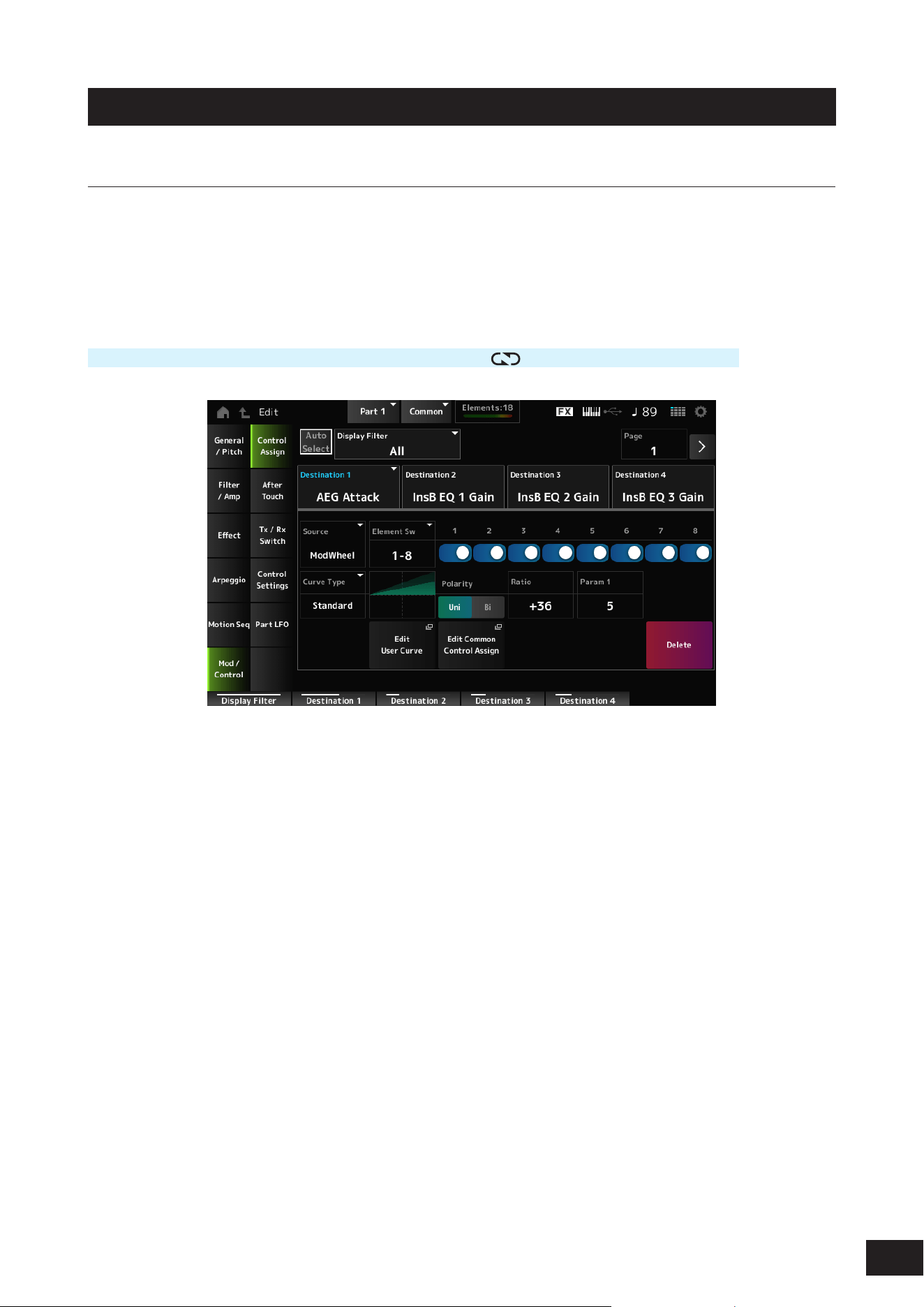
226
MODX M Operation Manual
Mod/Control
Control Assign
On the Control Assign screen, you can set the Controllers for the Part.
By assigning a parameter (Destination) to a controller (Source), you can control the sound in a large variety of ways. You
can use physical controllers such as the Pitch Bend wheel and knobs as well as the Motion Sequencer and Envelope
Follower.
Up to 32 controllers can be assigned simultaneously to a Part.
Operation
[PERFORMANCE (HOME)]
→
Part Common selection
→
[EDIT/ ]
→
Mod/Control
→
Control Assign
When Display Filter is set to Super Knob, tapping [+] shows the message in the upper area of the display and
automatically adds the Control Assign settings for the Common Edit.
NOTE
When there are no assignable knobs available, [+] will not be shown.
Auto Select
Switches the Auto Select setting of the Display Filter on or off.
When set to On, moving the controller you wish to set to Source automatically sets the controller to the Display Filter.
Settings: Off, On
Display Filter
Selects the controller for showing the settings on the screen.
When you select Super Knob, all settings having the Super Knob Link set to On will be shown.
Settings: PitchBend, ModWheel, Ch. AT, FootCtrl 1, FootCtrl 2, FootSwitch, Ribbon, Breath, AsgnKnob 1–8, Super Knob, AsgnSw 1,
AsgnSw 2, MS Lane 1–4, EnvFollow 1–16, EnvFollowAD, EnvFollowMst, All
NOTE
If the controller set to Display Filter is used by other Parts, the corresponding PART buttons will ash.

227
MODX M Operation Manual
Edit Pitch Bend
This calls up the Pitch settings screen. General/Pitch
→
Pitch will open.
This parameter is not shown when Source is set to something other than PitchBend.
Display Name (Assignable Knob Name)
This allows you to enter a new name for Knobs 1 to 8 to show on the Sub display.
This parameter is not shown when Source is set to something other than AsgnKnob 1–8.
Edit Motion Sequencer
Opens Motion Seq
→
Lane for the selected Part.
You can create a sequence of up to 16 steps.
This parameter is not shown when Source is set to something other than MS Lane 1–4.
Edit Envelope Follower
Opens the settings screen for the Envelope Follower.
This parameter is not shown when Source is set to something other than EnvFollow 1–16, EnvFollowAD, or
EnvFollowMst.
Page
Selects the next page when there are more than four Destinations. The next page does not appear when the Destinations
are four or fewer.
Settings: 1–8
Destination
Sets the parameter to the Destination. Tap [+] to add a Destination.
Source
Sets the controller for controlling the parameters set to the Destination.
Settings: PitchBend, ModWheel, Ch. AT, FootCtrl 1, FootCtrl 2, FootSwitch, Ribbon, Breath, AsgnKnob 1–8, AsgnSw 1, AsgnSw 2, MS
Lane 1–4, EnvFollow 1–16, EnvFollowAD, EnvFollowMst
Element Sw (Element Switch) 1–128
This parameter is shown only when the selected Destination is related to Elements.
You can set the controller setting for each Element on or off.
When General/Pitch
→
Element Settings Ex Elem Sw is set to On, you can select a different group of eight displayed
switch numbers.
However, the actual range of numbers you can use in the switch depends on the value set in the Element Count on the
General/Pitch
→
Element Settings screen.
(Example: If the Element Count is set to 30, the Groups that can be selected are 25–32).
Settings: (Each switch) Off, On, (Displayed switch numbers changed) 1–8, 9–16, ..., 121–128
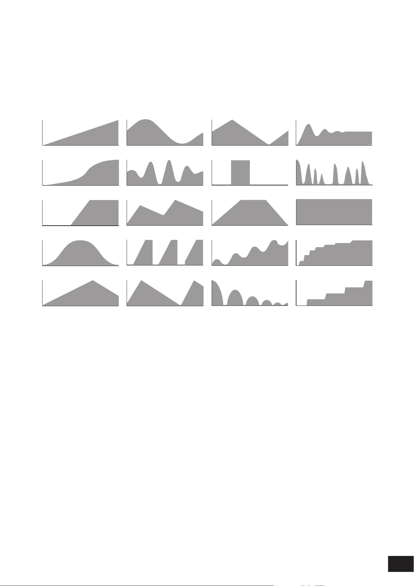
228
MODX M Operation Manual
Curve Type
Sets the change curve of the parameter set to Destination.
The horizontal axis represents the controller value set in Source while the vertical axis represents the parameter value set
in Destination.
Settings: Standard, Sigmoid, Threshold, Bell, Dogleg, FM, AM, M, Discrete Saw, Smooth Saw, Triangle, Square, Trapezoid, Tilt Sine,
Bounce, Resonance, Sequence, Hold, Harmonic, Steps (When a preset bank is selected)
Init Curve 1–32 (When a user bank is selected)
Curve within Library 1–24 (When loading a Library le)
Standard
Sigmoid
Threshold
Bell
Dogleg
FM
AM
M
Discrete Saw
Smooth Saw
Triangle
Square
Trapezoid
Tilt Sine
Bounce
Harmonic
Steps
Resonance
Sequence
Hold
Polarity (Curve Polarity)
Sets the polarity of the curve set in Curve Type.
Settings: Uni, Bi
Uni: Parameter changes occur only within the positive range or the negative range according to the curve shape
Bi: Parameter changes occur both in positive and negative ranges according to the curve shape
Ratio (Curve Ratio)
Sets the ratio of the parameter values.
Settings: −128–+0 –+127
Param 1 (Curve Parameter 1)
Param 2 (Curve Parameter 2)
Adjusts the curve shape.
This setting is not available depending on the curve type.
Destination to Name
Copies the parameters set to Destination to Display Name.
This parameter is not shown when Source is set to something other than AsgnKnob 1–8.
Edit User Curve
The User Curve Edit screen will open.
Edit Common Control Assign
Opens Control
→
Control Assign on the Common Edit screen.
Delete
Deletes the selected Destination.
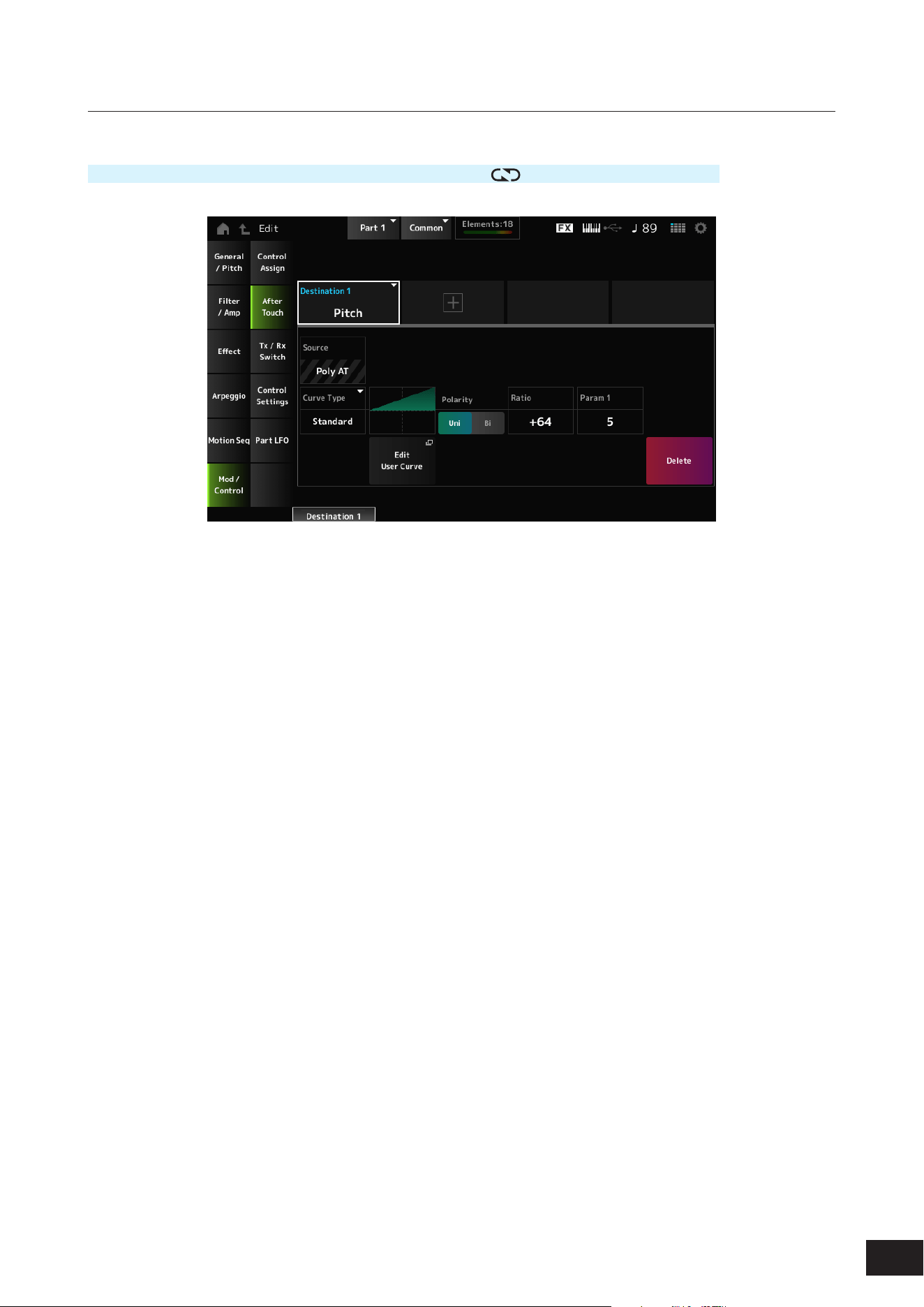
229
MODX M Operation Manual
After Touch
Operation
[PERFORMANCE (HOME)]
→
Part Common selection
→
[EDIT/ ]
→
Mod/Control
→
After Touch
Destination
Sets the parameter for the Destination. Tap [+] to add a Destination.
Source
Cannot be changed from this screen. This parameter is xed to Poly AT.
Element Sw (Element Switch) 1–128
Curve Type
Polarity (Curve Polarity)
Ratio (Curve Ratio)
Edit User Curve
Delete
The same as Mod/Control
→
Control Assign.
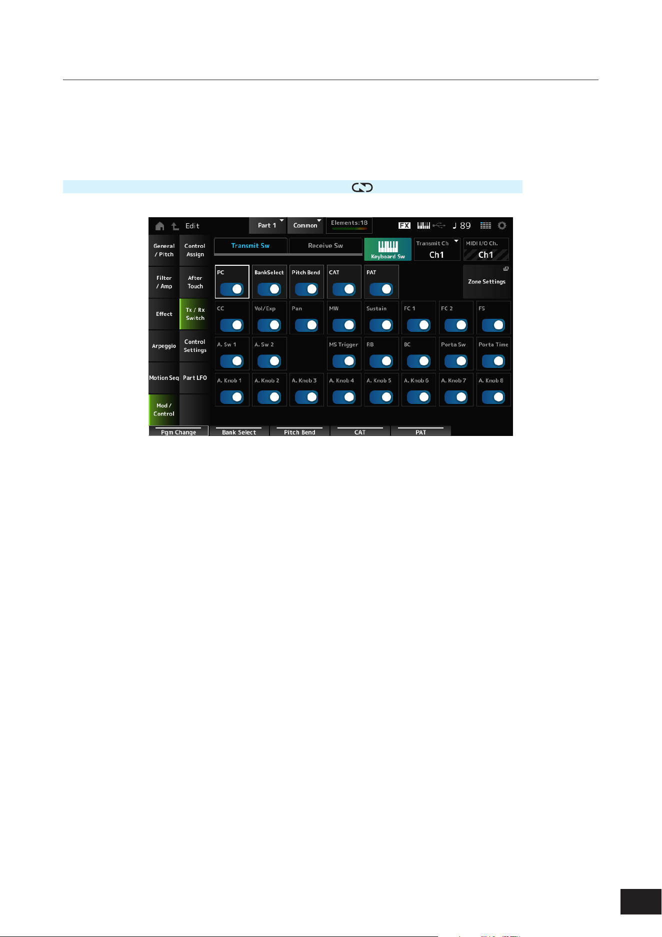
230
MODX M Operation Manual
Tx /Rx Switch
On the Tx/Rx Switch screen, you can set the switch for transmitting or receiving MIDI messages (such as Control Change)
on or off.
NOTE
When CC (Control Change) is set to Off, the parameters related to Control Change messages cannot be set.
Operation
[PERFORMANCE (HOME)]
→
Part Common selection
→
[EDIT/ ]
→
Mod/Control
→
Tx/Rx Switch
Transmit Sw (Transmit Switch)
Shows the transmit switch.
This parameter is available only when Part Mode is set to External or when Keyboard Sw is set to Off.
Receive Sw (Receive Switch)
Shows the receive switch.
Keyboard Sw (Keyboard Control Switch)
Sets the Parts to be played simultaneously.
When you select a Part with Common or Keyboard Sw set to On and play the keyboard, the Parts with Keyboard Sw set
to On will play simultaneously.
If the Keyboard Sw for the Part is set to Off, when you play the keyboard with that Part selected, those sounds will be
played.
Settings: Off, On
Tx/Rx Ch (Transmit/Receive Channel)
Sets the channel for transmitting and receiving MIDI messages when Part Mode is set to Internal.
Settings: Ch1–Ch16, Off
Transmit Ch.
Sets the channel for transmitting MIDI messages when Part Mode is set to External.
Settings: Ch1–Ch16
MIDI I/O Ch. (MIDI In-Out Channel)
Shows the channel for transmitting and receiving MIDI messages.

231
MODX M Operation Manual
Zone Settings
This calls up the Zone settings screen.
The same as General/Pitch
→
Zone Settings.
PC (Program Change)
Sets the transmission and reception of Program Change messages on or off.
Settings: Off, On
BankSelect (Bank Select)
Sets the transmission and reception of Bank Select MSB and LSB messages on or off. This parameter is not available
when CC (Control Change) is set to Off.
Settings: Off, On
Pitch Bend
Sets the transmission and reception of MIDI Pitch Bend messages on or off.
Settings: Off, On
CAT (Channel After Touch)
Sets the transmission and reception of Channel Aftertouch on or off.
Settings: Off, On
PAT (Polyphonic After Touch)
Sets the transmission and reception of Polyphonic Aftertouch on or off.
Settings: Off, On
CC (Control Change)
Sets the transmission and reception of Control Change messages on or off.
Settings: Off, On
Vol/Exp (Volume/Expression)
Sets the transmission and reception of the Volume setting on or off. This parameter is not available when CC (Control
Change) is set to Off.
Settings: Off, On
Pan
Sets the transmission and reception of the Pan setting on or off. This parameter is not available when CC (Control
Change) is set to Off.
Settings: Off, On
MW (Modulation Wheel)
Sets the transmission and reception of MIDI Modulation wheel messages on or off. This parameter is not available when
CC (Control Change) is set to Off.
Settings: Off, On
Sustain
Sets the transmission and reception of MIDI Sustain and Sostenuto messages on or off. This parameter is not available
when CC (Control Change) is set to Off.
Settings: Off, On
FC1 (Foot Controller 1)
FC2 (Foot Controller 2)
Sets the transmission and reception of MIDI messages for the separately sold foot controllers on or off. This parameter is
not available when CC (Control Change) is set to Off.
Settings: Off, On

232
MODX M Operation Manual
FS (Foot Switch)
Sets the transmission and reception of MIDI messages for the separately sold foot switch on or off. This parameter is not
available when CC (Control Change) is set to Off.
Settings: Off, On
A. Sw 1 (Assignable Function Switch 1)
A. Sw 2 (Assignable Function Switch 2)
Sets the transmission and reception of MIDI messages for the [ASSIGN 1] and [ASSIGN 2] buttons on or off. This
parameter is not available when CC (Control Change) is set to Off.
Settings: Off, On
MS Trigger (Motion Sequencer Trigger)
Sets the transmission and reception of MIDI messages for the [MSEQ TRIGGER] button on or off. This parameter is not
available when CC (Control Change) is set to Off.
Settings: Off, On
RB (Ribbon Controller)
Sets the transmission and reception of MIDI Ribbon Controller messages on or off. This parameter is not available when
CC (Control Change) is set to Off.
Settings: Off, On
BC (Breath Controller)
Sets the transmission and reception of MIDI Breath Controller messages on or off. This parameter is not available when
CC (Control Change) is set to Off.
Settings: Off, On
Porta Sw (Portamento Switch)
Sets the transmission and reception of MIDI messages for the [PORTAMENTO] button on or off. This parameter is not
available when CC (Control Change) is set to Off.
Settings: Off, On
Porta Time (Portamento Time)
Sets the transmission and reception of MIDI messages for the PORTAMENTO [TIME] knob on or off. This parameter is
not available when CC (Control Change) is set to Off.
Settings: Off, On
A. Knob 1–8 (Assignable Knob)
Sets the transmission and reception of MIDI messages for Knobs 1 to 8 on or off. This parameter is not available when
CC (Control Change) is set to Off.
Settings: Off, On
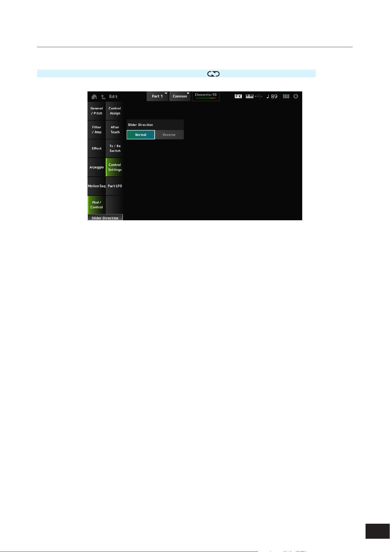
233
MODX M Operation Manual
Control Settings
Operation
[PERFORMANCE (HOME)]
→
Part Common selection
→
[EDIT/ ]
→
Mod/Control
→
Control Settings
Slider Direction
Sets the direction of the Control sliders 1 to 8 for this Part when the slider Mode is set to ELEM/OP/OSC.
When set to Reverse, the volume controls on the screen will change to organ sliders. The organ sliders will be shown
when you select a Part and set the View Mode to Part Info.
Settings: Normal (up from the bottom), Reverse (down from the top)
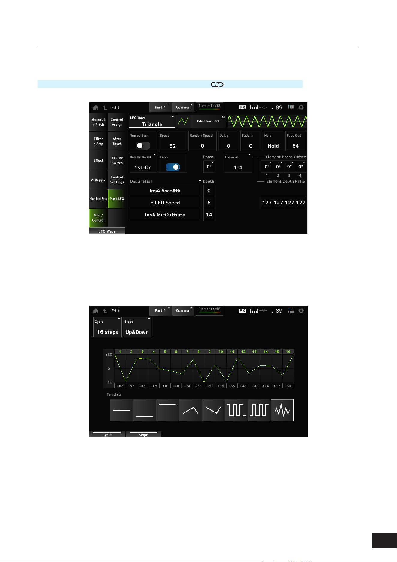
234
MODX M Operation Manual
Part LFO
On the Part LFO screen, you can set the Part LFO.
Operation
[PERFORMANCE (HOME)]
→
Part Common selection
→
[EDIT/ ]
→
Mod/Control
→
Part LFO
LFO Wave
Selects the LFO Wave and sets the type of cyclical changes to the LFOs.
Settings: Triangle, Triangle+, Saw Up, Saw Down, Squ1/4, Squ1/3, Square, Squ2/3, Squ3/4, Trapezoid, S/H1, S/H2, User
Edit User LFO
The User LFO Edit screen will open.
You can create an LFO waveform of up to 16 steps.
• Cycle
Sets the number of LFO steps.
Settings: 2 steps, 3 steps, 4 steps, 6 steps, 8 steps, 12 steps, 16 steps
• Slope
Sets the changes to the slope of the waveform currently shown on the screen.
Settings: Off (no slope), Up, Down, Up&Down

235
MODX M Operation Manual
• User LFO Step Value
Sets the value for each step.
Settings: −64–+0–+63
• Template
Selects the template for the LFO waveform.
Tempo Sync (LFO Tempo Sync)
Sets the speed of the LFO Wave changes to synchronize to Arpeggio or Song playback.
Settings: Off (not synchronized), On (synchronized)
• When set to Off
Speed (LFO Speed)
Sets the speed of LFO Wave changes.
This parameter is not available when Tempo Sync (LFO Tempo Sync) is set to On.
Settings: 0–63
Random Speed (Part LFO Random Speed Depth)
Changes the LFO Speed randomly.
This parameter is not available when Tempo Sync (LFO Tempo Sync) is set to On.
Settings: 0–127
• When set to On
Tempo Speed (LFO Tempo Speed)
Sets the speed of LFO Wave changes by using musical note values.
Settings: 1/16 (sixteenth notes), 1/8 Tri. (eighth-note triplets), 1/16 Dot. (dotted sixteenth notes), 1/8 (eighth notes), 1/4 Tri. (quarter-note
triplets), 1/8 Dot. (dotted eighth notes), 1/4 (quarter notes), 1/2 Tri. (half-note triplets), 1/4 Dot. (dotted quarter notes), 1/2 (half
notes), Whole Tri. (whole-note triplets), 1/2 Dot. (dotted half notes), 1/4 × 4 (quarter-note quadruplets; four quarter notes to
the beat), 1/4 × 5 quarter-note quintuplets; ve quarter notes to the beat), 1/4 × 6 (quarter-note sextuplets; six quarter notes
to the beat), 1/4 × 7 (quarter-note septuplets; seven quarter notes to the beat), 1/4 × 8 (quarter-note octuplets; eight quarter
notes to the beat), 1/4 × 16 (sixteen quarter-notes to the beat), 1/4 × 32 (thirty-two quarter-notes to the beat), 1/4 × 64 (sixty-
four quarter-notes to the beat)
Delay (LFO Delay Time)
Sets the delay time between the moment you press a key on the keyboard and the moment the LFO comes into effect.
The larger the value, the longer the delay time for the LFO to come into effect.
Settings: 0–127
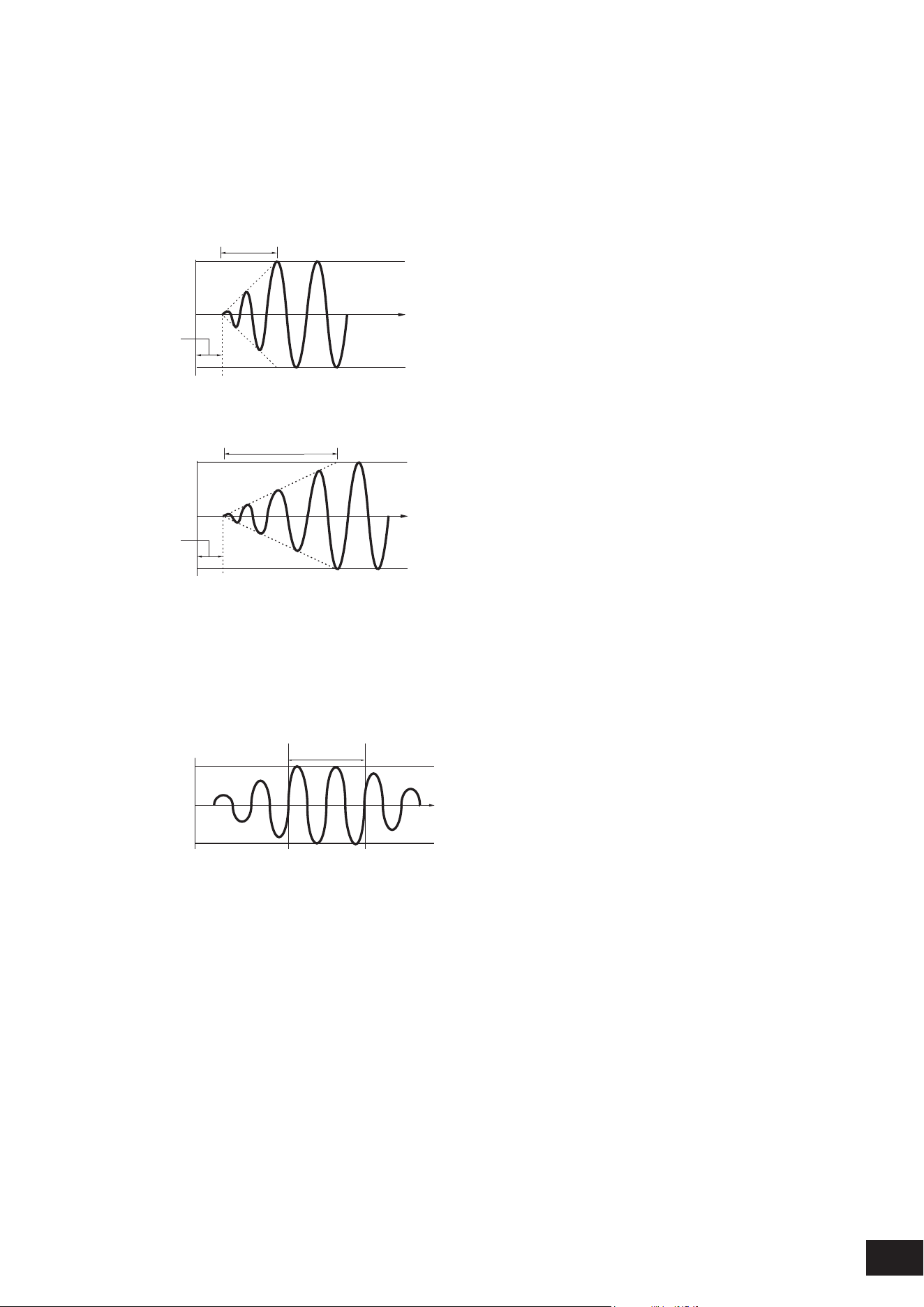
236
MODX M Operation Manual
Fade In (LFO Fade In Time)
Sets the time length for the LFO effect to fade in after you have released the key and the delay time set in Delay (LFO
Delay Time) has elapsed. The larger the value, the longer it takes for the LFO effect to reach the maximum.
Settings: 0–127
0: The LFO changes to the maximum value without any fade-ins.
When the value is small
Fade In
Maximum
Delay
Key On
Time
When the value is large
Fade In
Maximum
Delay
Key On
Time
Hold (LFO Hold Time)
Sets the time for maintaining the LFO effect after the maximum level has been reached.
Settings: 0–126, Hold
Hold: Does not fade out
Hold
Maximum
Key On
Time
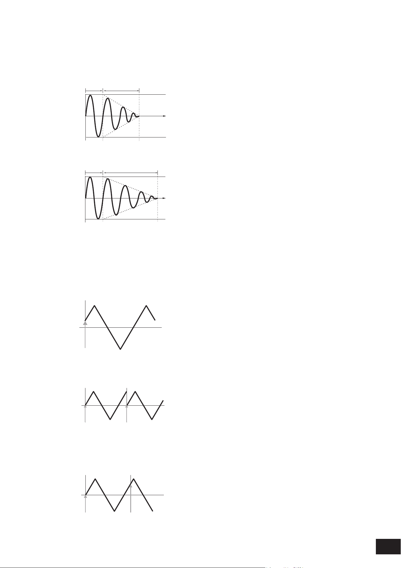
237
MODX M Operation Manual
Fade Out (LFO Fade Out time)
Sets the amount of time for the LFO effect to fade out after the hold time set in Hold (LFO Hold Time) has elapsed. The
larger the value, the longer it takes for the LFO effect to fade out.
Settings: 0–127
When the value is small
Fade-Out
Maximum
Hold
Key On
Time
When the value is large
Fade-Out
Maximum
Hold
Key On
Time
Key On Reset (LFO Key On Reset)
Resets the oscillation of the LFO when a key is pressed.
Settings: Off, Each-on, 1st-on
When set to Off
Does not reset the oscillation of the LFO. Pressing a key starts the LFO wave at whatever phase the LFO happens to be at
that moment.
Key On
Time
When set to Each-on
Resets the oscillation of LFO every time a key is pressed and starts the waveform at the phase specied by the Phase
parameter.
Key On
(first note)
Key On
(second note)
Time
When set to 1st-on
Resets the oscillation of LFO every time a key is pressed and starts the waveform at the phase specied by the Phase
parameter.
When the second note is played while the rst note is held, playback will not be reset.
Key On
(first note)
Key On
(second note)
Time

238
MODX M Operation Manual
Loop (LFO Loop Switch)
Sets the LFO Wave to loop (repeat) playback or one-shot playback.
Settings: Off, On
Phase (LFO Phase)
You can set the initial phase for the time the LFO Wave is reset.
Settings: 0°, 90°, 120°, 180°, 240°, 270°
Phase
Time
Level
0°
90°
120°
240°
180° 270°
Element Phase Offset (LFO Element Phrase Offset)
Sets the offset value to Phase (LFO Phase) for each Element.
Settings: 0°, 90°, 120°, 180°, 240°, 270°
Element (Display Element)
You can select a different number for the group of four elements corresponding to Element Phase Offset and Element
Depth Ratio when General/Pitch
→
Element Settings Ex Elem Sw is On. However, the actual range of numbers you
can use in the switch depends on the value set in the Element Count on the General/Pitch
→
Element Settings screen
(Example: If the Element Count is set to 30, the Groups that can be selected are 29–32).
Settings: 1–4, 5–8, ..., 125–128
Element Phase Offset (LFO Element Phase Offset)
Sets the offset value to Phase (LFO Phase) for each Element.
You can set the initial phase for each Element when LFO Wave is reset.
When the Ex Elem Sw on the General/Pitch
→
Element Settings screen is set to On, you can change the element number
by changing the Element (Display Element). Up to the value set in General/Pitch
→
Element Settings Element Count is
shown.
Element Depth Ratio (LFO Element Depth Ratio)
Adjusts the Depth for each Element. Set this parameter to Off to turn off the LFO.
This parameter is shown only when the selected Destination is related to Elements.
When General/Pitch
→
Element Settings Ex Elem Sw is set to On, the adjusted Depth element number can be changed
with Element (Display Element).
Up to the value set in General/Pitch
→
Element Settings Element Count is shown.
Settings: Off, 0–127
Destination (LFO Destination)
Sets the function to be controlled by the LFO Wave.
Settings: Insertion Effect A Parameter 1–24, Insertion Effect B Parameter 1–24, Level, Pitch, Cutoff, Resonance, Pan,
E.LFO Speed
Depth (LFO Depth)
Sets the depth of LFO Wave control for each Destination.
Settings: 0–127
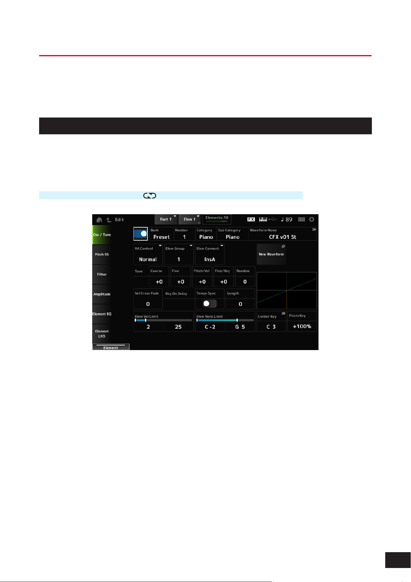
239
MODX M Operation Manual
Part Edit (AWM2) Element Edit Screens
A Normal Part (AWM2) consists of up to 128 elements.
Part Edit (AWM2) includes Part Common Edit (for setting parameters for the entire Part) and Element Edit (for setting
parameters for each Element in the Part).
Osc/ Tune
On the Osc/Tune screen, you can set the Oscillator for the Element.
Here, you can select the Waveform used as the basis for the sound and set the key range and velocity range of the
Element.
Operation
[PERFORMANCE (HOME)]
→
[EDIT/ ]
→
Part selection
→
Element selection
→
Osc/ Tune
Element Switch
Sets the selected Element on or off.
Settings: Off, On
Bank (Waveform Bank)
Number (Waveform Number)
Category (Waveform Category)
Sub Category (Waveform Sub Category)
Waveform Name
Shows the name of the Waveform selected for the Element.
Bank indicates the type of Waveform (Preset, User, and Library) assigned to the Element.
Settings: Refer to the Data List

240
MODX M Operation Manual
XA Control
XA (Expanded Articulation) is a function for creating realistic sounds like those on acoustic instruments as well as creating
new synth sounds.
You can create such sounds by setting the XA Control to specify the way the Element is played.
Settings: Normal, Legato, Key Off, Cycle, Random, A.Sw Off, A.Sw1 On, A.Sw2 On
Normal: Played as a normal Element.
Legato: Played when Mono/Poly is set to Mono. When you play in Legato, the Element set to Legato will be played instead of
the Element set to Normal
Key Off: Played when a nger is lifted off from the key
Cycle: Played when there are a series of Elements set in Cycle
Random: Plays the Elements randomly when multiple Elements are set to Random
A.Sw Off: Played when both [ASSIGN 1] and [ASSIGN 2] buttons are set to Off.
A.Sw1 On: Played when the [ASSIGN 1] button is set to On.
A.Sw2 On: Played when the [ASSIGN 2] button is set to On.
Example of XA Control setting
• Creating smooth legato
Make the Element alternate between one element with XA Control set to Normal and another element with the XA
Control set to Legato.
• Creating the sound that is produced when you release a key
Create an Element with XA Control set to Key Off.
• Creating randomness for the same note
Make the Element with XA Control set to Cycle and another one with XA Control set to Random.
• Producing sounds unique to acoustic instruments, such harmonics and palm mute on the guitar, utter-tonguing on the
ute, and growl on the saxophone
Set up an Element with XA Control set to A.Sw Off, A.Sw1 On, or A.Sw2 On, and control from the [ASSIGN 1] and
[ASSIGN 2] buttons on the top panel.
NOTE
The [ASSIGN 1] and [ASSIGN 2] buttons can be set to On or Off by sending the Control Change number set in Control
→
Control
Number on the Common Edit screen from an external device.
Elem Group (Element Group Number)
This parameter is for sorting Elements having the same XA Control setting into groups.
When XA Control of all Elements is set to Normal, this setting is not effective.
Settings: 1–8
Elem Connect (Element Connection Switch)
Sets the output of the Element to Insertion Effect A or Insertion Effect B.
Setting it to Thru bypasses the Insertion Effects.
Settings: Thru, InsA, InsB
New Waveform
Loads an audio le saved to USB ash drive as a Waveform.
Edit Waveform appears when a Waveform is loaded.
Edit Waveform
The Waveform Edit screen will open.
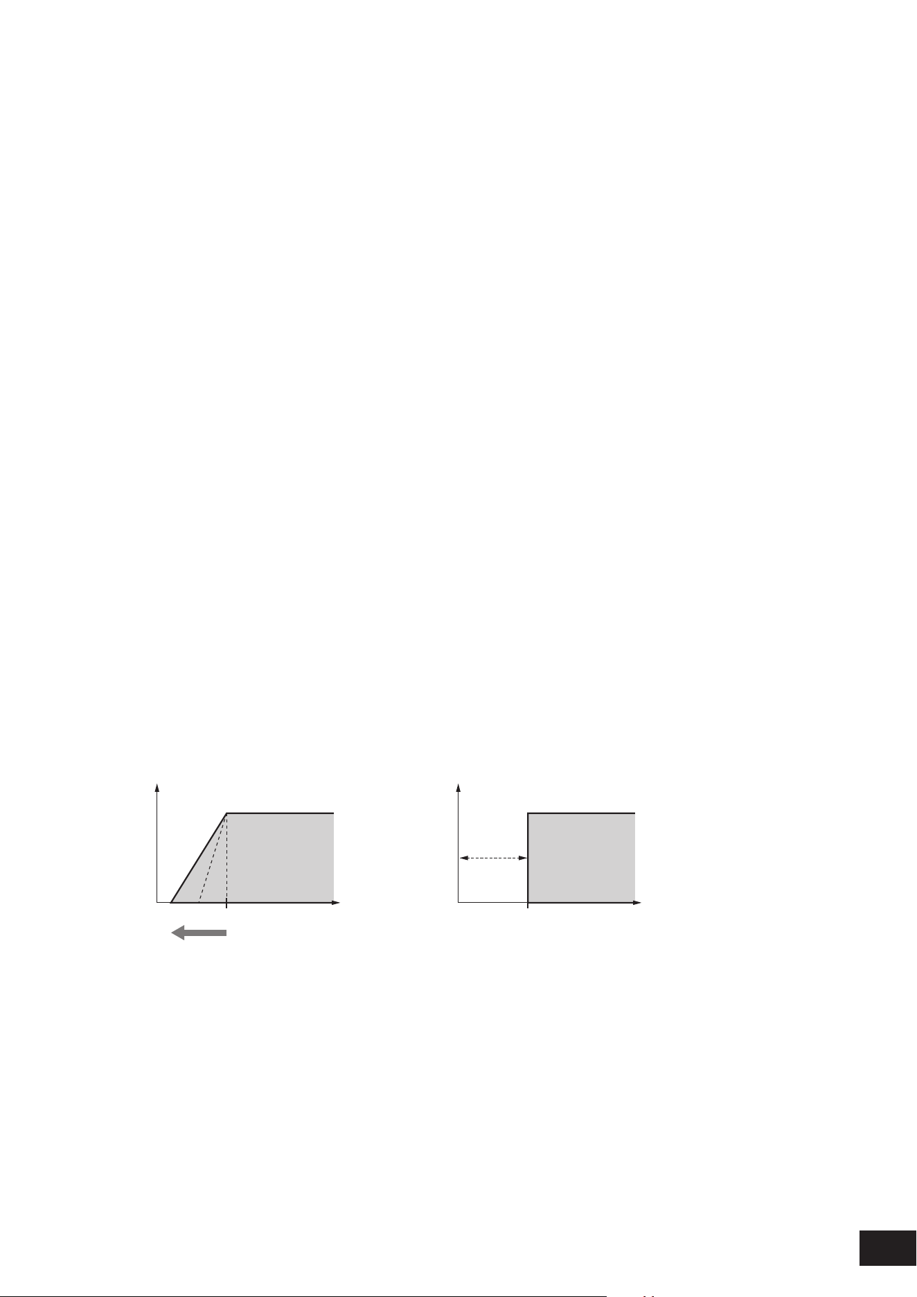
241
MODX M Operation Manual
Coarse (Coarse Tune)
Shifts the pitch of the Element in semitones.
Settings: −48–+0–+48
Fine (Fine Tune)
Finely adjusts the pitch of the Element.
Settings: −64–+0–+63
Pitch/Vel (Pitch Velocity Sensitivity)
Sets how the pitch change responds to Velocity or the strength of the keystroke.
Settings: −64–+0–63
Positive value: The faster the Velocity, the higher the pitch becomes
0: kept unchanged
Negative value: The faster the Velocity, the lower the pitch becomes
Fine/Key (Fine Tune Key Follow Sensitivity)
Sets how the pitch change in the Fine Tuning responds to the position of the key.
Settings: −64–+0–63
Positive value: The pitch goes down when you press a key in the bass section, and the pitch goes up when you press a key
in the treble section
Negative value: The pitch goes up when you press a key in the bass section, and the pitch goes down when you press a key
in the treble section
Random (Random Pitch Depth)
Changes the pitch of the Element randomly each time a key is pressed.
Set the parameter to a larger value to create more pitch changes. When the value is set to 0, the pitch is kept unchanged.
Settings: 0–127
Vel Cross Fade (Velocity Cross Fade)
Sets the output level of the Oscillator to become lower as keystroke Velocity values outside the Velocity Limit become
further from the value set in Velocity Limit.
The larger the value, the more gradually the way the output level of the Oscillator decreases. When set to 0, no sound is
produced if the Velocity is outside the Velocity Limit.
Settings: 0–127
When Level/Vel is set to +0
Output
Velocity
Velocity Limit Low
(1)
(2)
Output
Velocity
Velocity Limit Low
Vel Cross Fade = 0
(1) When a larger value is used, the slope will be shifted to the left
(2) When set to 0, no sound is produced if the Velocity is outside the Velocity Limit

242
MODX M Operation Manual
Key On Delay Tempo Sync (Key On Delay Tempo Sync Switch)
Sets the timing of the Key On Delay to synchronize with the tempo.
Settings: Off, On
Key On Delay Length (Key On Delay Time Length)
Sets the delay time from when the moment the key is pressed to when sound is produced.
This parameter is not available when Key On Delay Tempo Sync (Key On Delay Tempo Sync Switch) is set to On.
Settings: 0–127
Length (Key On Delay Note Length)
You can set the timing for Key On Delay by using musical note values.
This parameter is available when Key On Delay Tempo Sync (Key On Delay Tempo Sync Switch) is set to On.
Settings: 1/16 (sixteenth notes), 1/8 Tri. (eighth-note triplets), 1/16 Dot. (dotted sixteenth notes), 1/8 (eighth notes), 1/4 Tri. (quarter-note
triplets), 1/8 Dot. (dotted eighth notes), 1/4 (quarter notes), 1/2 Tri. (half-note triplets), 1/4 Dot. (dotted quarter notes), 1/2 (half
notes), Whole Tri. (whole-note triplets), 1/2 Dot. (dotted half notes), 1/4 × 4 (quarter-note quadruplets; four quarter notes to the
beat), 1/4 × 5 (quarter-note quintuplets; ve quarter notes to the beat), 1/4 × 6 (quarter-note sextuplets; six quarter notes to the
beat), 1/4 × 7 (quarter-note septuplets; seven quarter notes to the beat), 1/4 × 8 (quarter-note octuplets; eight quarter notes to
the beat)
Velocity Limit
Sets the velocity range (lowest and highest values) for playing the Element wave.
When this is set so that the higher value is rst and the lower value is second (for example, 93 to 34), the Element sounds
only for velocities of 1 to 34 and 93 to 127.
Settings: 1–127
Note Limit
Sets the note range (lowest and highest notes) for the Element.
When the rst note specied is higher than the second (for example, C5 to C4), the Element is played in the ranges C2 to
C4 and C5 to G8.
Settings: C−2–G8
Center Key (Pitch Key Follow Sensitivity Center Key)
Sets the reference key (note) for Pitch/Key (Pitch Key Follow Sensitivity).
The key set with the note number here is played at the normal pitch regardless of the Pitch/Key setting.
Settings: C−2–G8
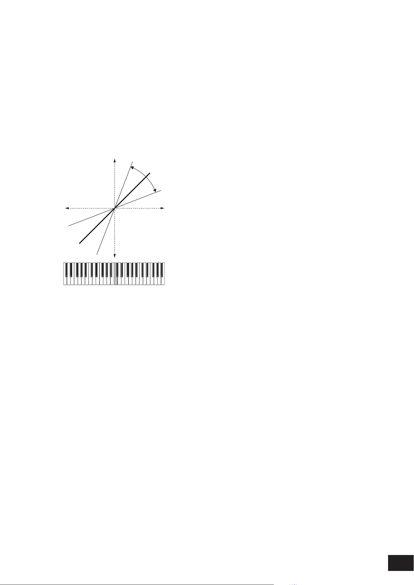
243
MODX M Operation Manual
Pitch/Key (Pitch Key Follow Sensitivity)
Sets the difference in pitch between two adjacent keys. The reference note is specied by Center Key (Pitch Key Follow
Sensitivity Center Key).
This parameter is useful for playing unpitched sounds, such as special effects, or for playing a percussion instrument as
a Normal Part, or for any other cases where the pitch difference does not have to be in semitones.
Settings: −200%–+0%–+200%
+100% (normal setting): Pitch difference between the two keys next to each other is set to a semitone
0%: No pitch difference between the two keys, and all keys are played at the pitch set in Center Key
Negative value: Sets an opposite pitch response such that lower notes result in higher pitch, and higher notes result in lower
pitch.
Pitch/Key and Center Key
(2)
(1)
(3)
(4)
(5)
+
–
High
+100%
+150%
+50%
Low
(1) Key
(2) Amount of change in pitch
(3) Center Key
(4) The pitch difference between adjacent keys becomes larger
(5) The pitch difference between adjacent keys becomes smaller
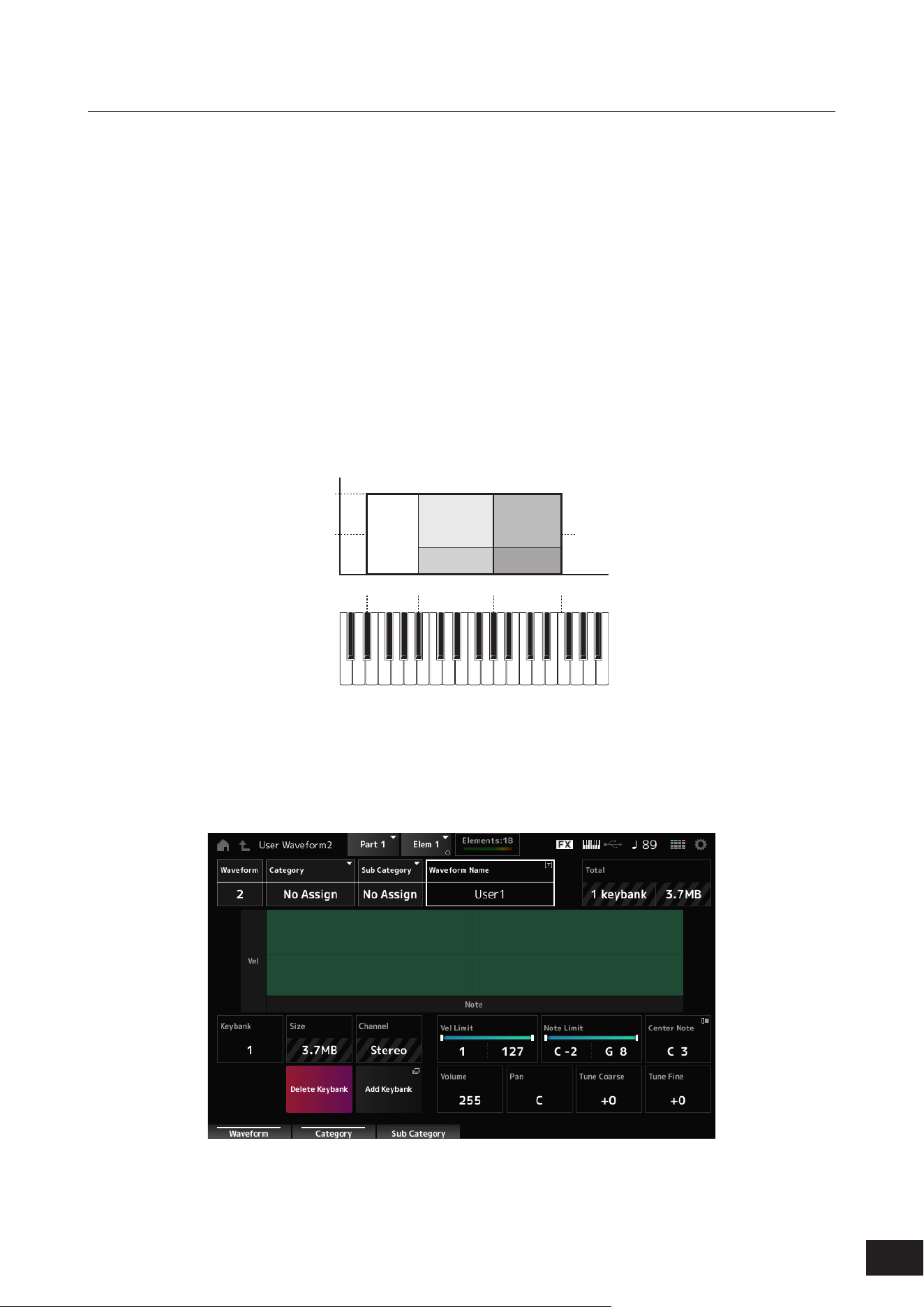
244
MODX M Operation Manual
Waveform Edit
Opens the Waveform Edit screen.
Here, you can set the various Key Banks that make up a Waveform.
Key Banks
A Key Bank is digital data comprised of a short audio segment, such as vocals or other sounds, loaded into the
instrument. It has the same characteristics as a .wav le; however, to avoid confusion a different name is used to
distinguish it from the Waveform.
Key Banks and Waveforms
Key Banks are always saved as a part of a Waveform.
A Waveform can contain multiple Key Banks, allowing you to save dozens of Key Banks in a single Waveform.
However, if all of the Key Banks sound simultaneously, it would become unmanageable, so you can set the range of keys
(Note Limit) and velocity range (Velocity Limit) that will sound for each Key Bank. By setting up multiple Key Banks, you
can play various Key Bank sounds depending on the section of the keyboard you use and the strength of your keystroke.
Example of Key Bank and Waveform setup
Velocity
Waveform
Key
Bank 1
Key Number
(Note Number)
40
127
D
♯
2 A
♯
2 G
♯
3
F4
Key Bank 2 Key Bank 4
Key Bank 3 Key Bank 5
Parts and waveforms
Waveforms can be incorporated into Parts and played on the keyboard.
You can assign one waveform per element to a part using Part Edit (AWM2), Element Edit, Drum Part Edit (AWM2) and
Key Edit.

245
MODX M Operation Manual
Waveform
Shows the name of the selected Waveform.
Category (Waveform Category)
Sub Category (Waveform Sub Category)
Sets the Main category and Sub category of the selected Waveform.
Settings: Refer to the Data List
Name (Waveform Name)
You can save the Waveform you are editing under a new name, You can use up to 20 alphanumeric characters.
Total
Shows the number of Key Banks in the waveform and the total size of the data capacity.
Keybank (Keybank Number)
Shows the Key Bank number.
Size (Keybank Size)
Shows the total size of data capacity.
Channel (Keybank Channel)
Shows whether the Key Bank is stereo or mono.
Velocity Limit
Sets the velocity range (lowest and highest values) for playing the Key Bank.
Settings: 1–127
Note Limit
Sets the note range (lowest and highest notes) for playing the Key Bank.
Settings: 1–127
Center Note
Sets the key (pitch) of the original waveform data.
Settings: C−2–G8
Volume
Sets the volume of the Key Bank.
Settings: 0–255
Pan
Sets the Pan position (in the stereo eld) of the Key Bank.
Settings: L63–C (center)–R63
Tune Coarse (Coarse Tune)
Shifts the pitch of the Key Bank in semitones.
Settings: −64–+63
Tune Fine (Fine Tune)
For ne pitch adjustment of the Key Bank.
Settings: −64–+63
Delete Keybank
Deletes the Key Bank.
Add Keybank
Adds a Key Bank to the waveform.
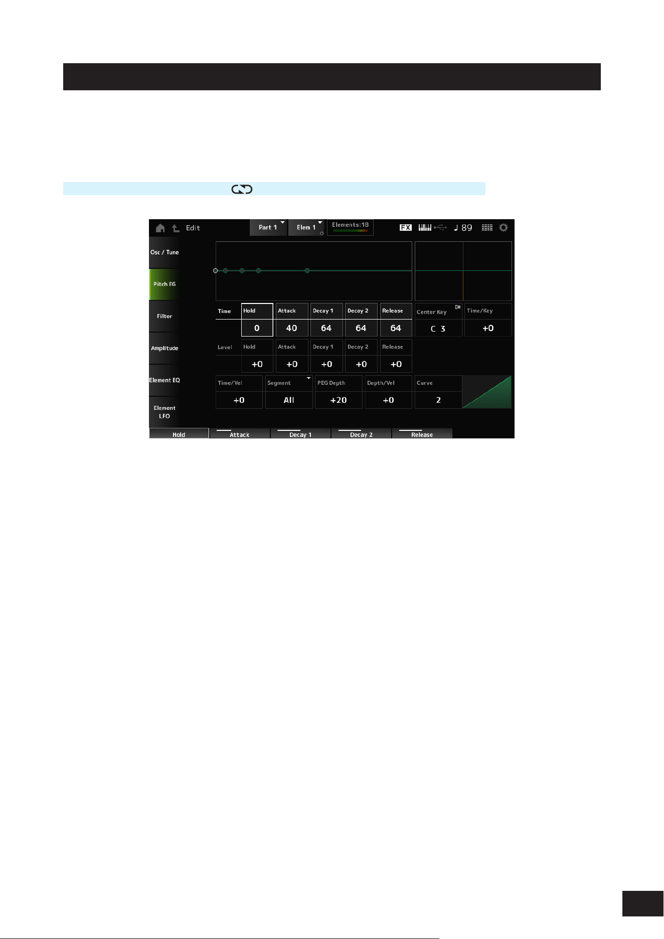
246
MODX M Operation Manual
Pitch EG
The Pitch EG screen lets you set the Envelope Generator for the Oscillator.
By setting the PEG (Pitch Envelope Generator) time and level (the amount of pitch change), you can set how the sound
changes from the moment you press a key on the keyboard to when the sound decays to silence.
Operation
[PERFORMANCE (HOME)]
→
[EDIT/ ]
→
Part selection
→
Element selection
→
Pitch EG
Hold Time (PEG Hold Time)
Sets the length of time it takes for keeping the pitch at Hold Level (PEG Hold Level) starting from the moment you press
a key on the keyboard.
Settings: 0–127
Attack Time (PEG Attack Time)
Sets the length of time it takes for the pitch to change from the end of the Hold Time (PEG Hold Time) to the Attack Level
(PEG Attack Level).
Settings: 0–127
Decay1 Time (PEG Decay 1 Time)
Sets the length of time it takes for the pitch to change from the Attack Level (PEG Attack Level) to the Decay1 Level (PEG
Decay 1 Level).
Settings: 0–127
Decay2 Time (PEG Decay 2 Time)
Sets the length of time it takes for the pitch to change from the Decay1 Level (PEG Decay 1 Level) to the Decay2 Level
(PEG Decay 2 Level).
Settings: 0–127
Release Time (PEG Release Time)
Sets the length of time it takes for the pitch to change from the moment you have released the key until it reaches the
Release Level (PEG Release Level).
Settings: 0–127
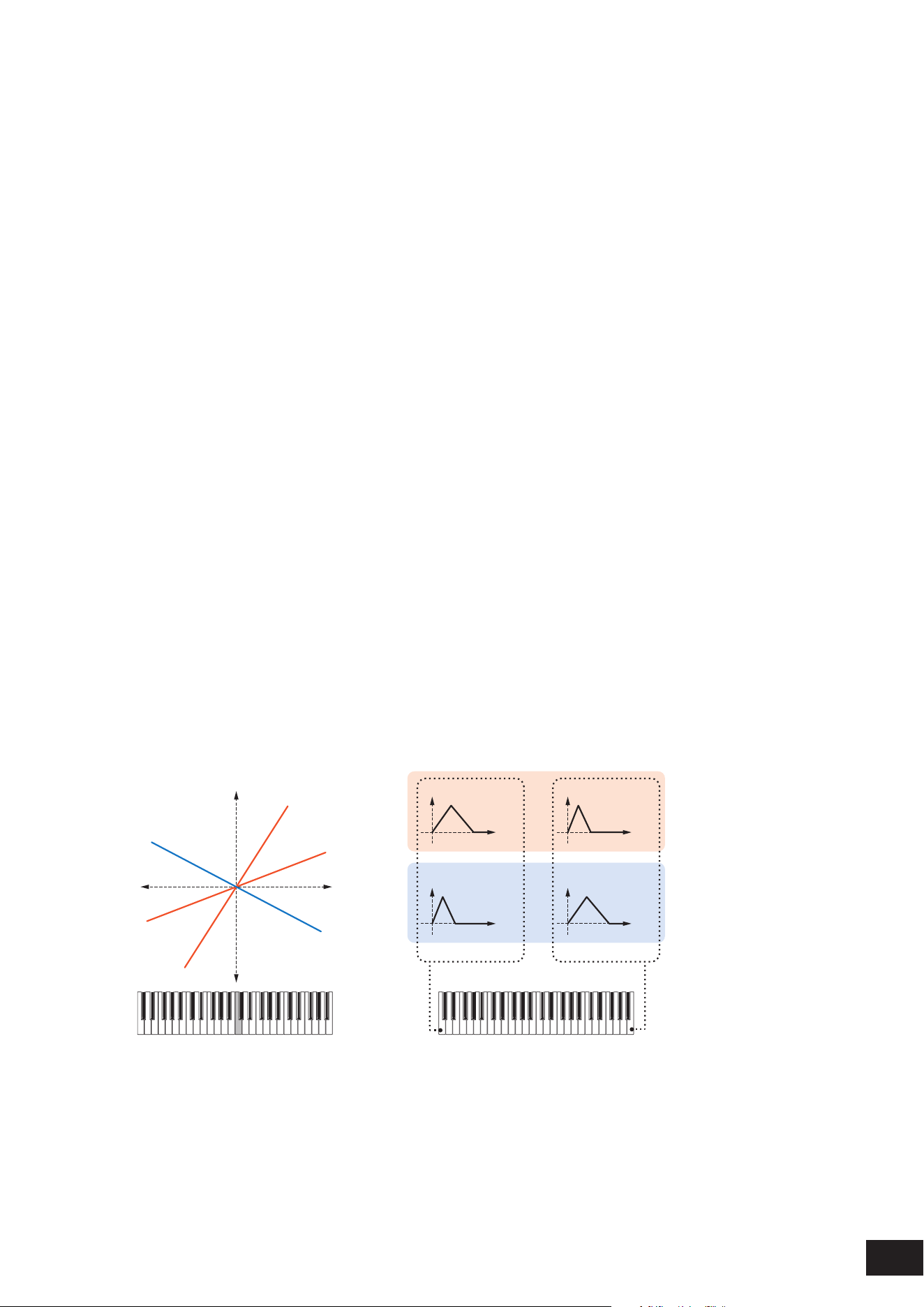
247
MODX M Operation Manual
Hold Level (PEG Hold Level)
Sets the pitch for the moment you press the key.
Settings: −128–+0 –+127
Attack Level (PEG Attack Level)
Sets the change in pitch from the Hold Level or the moment you press a key.
Settings: −128–+0 –+127
Decay1 Level (PEG Decay 1 Level)
Sets the next pitch value to change from the Attack Level (PEG Attack Level).
Settings: −128–+0 –+127
Decay2 Level (PEG Decay 2 Level)
Sets the next pitch value to change from the Decay1 Level (PEG Decay 1 Level).
Settings: −128–+0 –+127
Release Level (PEG Release Level)
Sets the nal pitch to reach after you have released the key.
Settings: −128–+0 –+127
Center Key (PEG Time Key Follow Sensitivity Center Key)
Sets the reference key (note) for Time/Key (PEG Time Key Follow Sensitivity).
With the note (key) set here, the resulting sound of the pitch change set in PEG is played.
Settings: C−2–G8
Time/Key (PEG Time Key Follow Sensitivity)
Sets how the speed of the pitch change in PEG responds to key position.
The change speed in PEG is used for the specied key in Center Key (PEG Time Key Follow Sensitivity Center Key).
Settings: −64–+0–+63
Positive value: The lower the key played, the slower the change in the PEG; the higher the key played, the faster the change
in the PEG.
0: No PEG changes regardless of the key position
Negative value: The higher the key pressed, the slower the pitch changes of the PEG.
Center Key and Time/key
(2)
(1)
(3)
High
Fast
Slow
+63
+30
−40
Low
Time
(6)
Time
(6)
Time
(6)
Time
(6)
(4)
(5)
Low key High key
(1) Key
(2) The speed of the pitch change in PEG
(3) Center Key
(4) When Time/Key is positive
(5) When Time/Key is negative
(6) Pitch
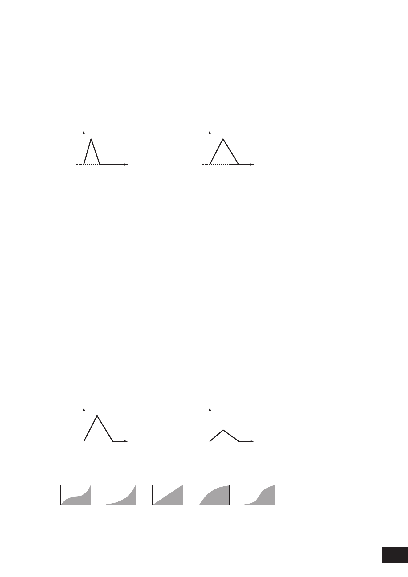
248
MODX M Operation Manual
Time/Vel (PEG Time Velocity Sensitivity)
Segment (PEG Time Velocity Sensitivity Segment)
Sets how the time of the pitch change in PEG responds to Velocity or the strength of the keystroke.
First, set the time value in Segment , and then the velocity sensitivity value in Time/Vel.
Settings: Time/Vel: −64–+0–+63
Positive value: The faster the Velocity, the faster the pitch changes in the PEG
0: No PEG changes regardless of the velocity setting.
Negative value: The faster the Velocity, the slower the pitch changes in the PEG
When the value is positive
Fast Velocity (pitch change is fast) Slow Velocity (pitch change is slow)
Time
(1)
Time
(1)
(1) Pitch
Settings: Segment: Attack, Atk+Dcy, Decay, Atk+Rls, All
Attack: The Time/Vel value affects the Attack Time
Atk+Dcy: The Time/Vel value affects the Attack Time and Decay1Time
Decay: The Time/Vel value affects the Decay Time
Atk+Rls: The Time/Vel value affects the Attack Time and Release Time
All: The Time/Vel value affects the time-related settings in PEG
PEG Depth
Sets the amount of pitch change controlled by the PEG. The further the depth is from the value 0, the wider the pitch
change range becomes.
Settings: −64–+0–+63
0: kept unchanged
Negative value: Pitch change is inverted.
Depth/Vel (PEG Depth Velocity Sensitivity)
Curve (PEG Depth Velocity Sensitivity Curve)
Sets how the depth range of the pitch change controlled by the PEG responds to Velocity or the strength of the keystroke.
Also, with the Curve setting, you can set how the PEG Depth responds to the Velocity. The vertical axis represents
velocity while the horizontal axis represents the depth range of the pitch change.
Settings: Depth/Vel: −64–+0–+63
Positive value: Faster Velocity values widen the depth range of the pitch change controlled by the PEG, while slower values
narrow the depth range
0: No PEG changes regardless of the velocity setting.
Negative value: Faster Velocity values narrow the depth range of the pitch change controlled by the PEG, while slower
values widen the depth range
When the value is positive
Fast Velocity (the depth range in pitch change is wider) Slow Velocity (the depth range in pitch change is narrower)
Time
(1)
Time
(1)
(1) Pitch Depth
Settings: Curve: 0–4
0 31 42
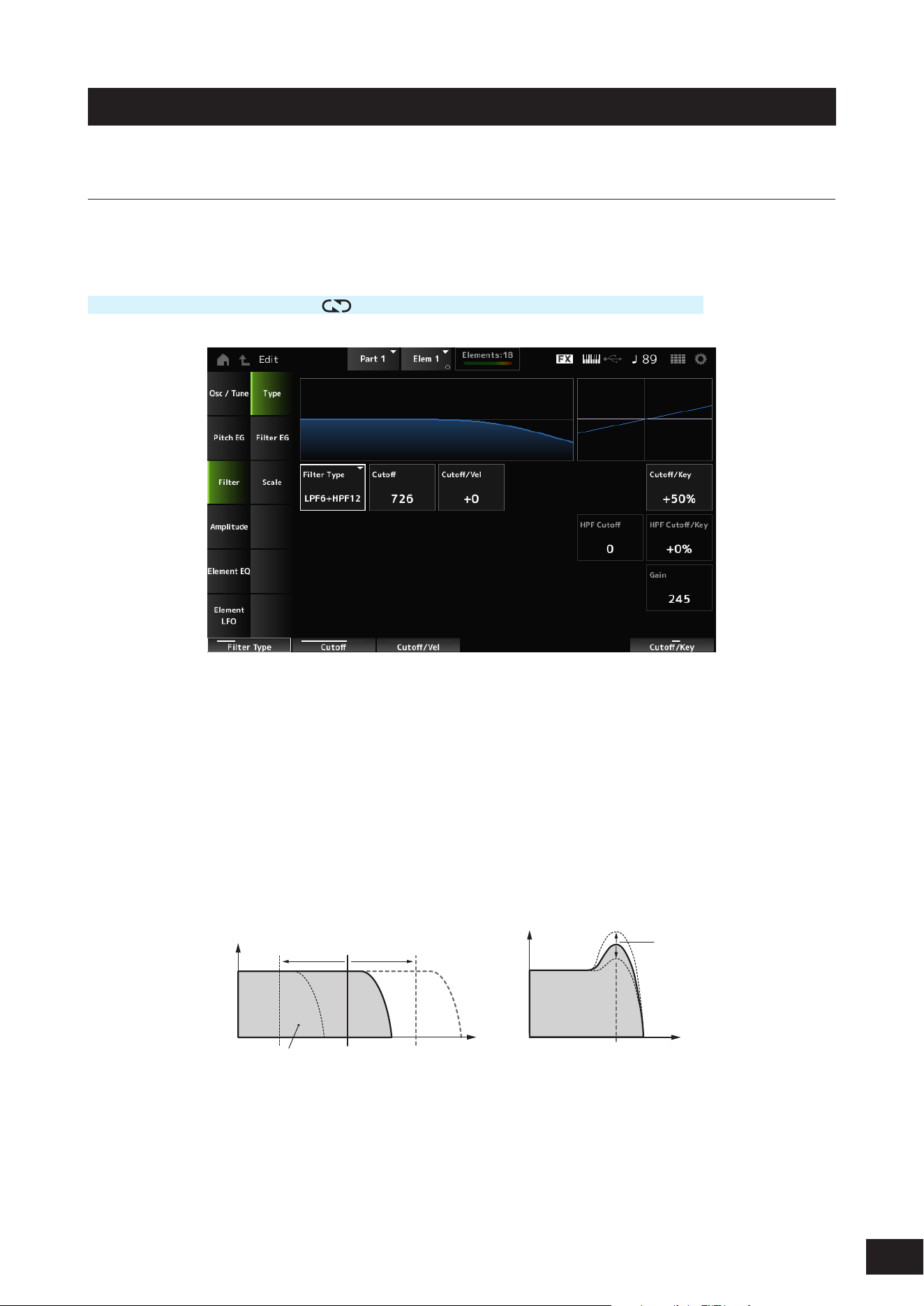
249
MODX M Operation Manual
Filter
Type
On the Type screen, you can select a lter type for the Element. The available parameters differ depending on the lter
type you have selected here.
Operation
[PERFORMANCE (HOME)]
→
[EDIT/ ]
→
Part selection
→
Element selection
→
Filter
→
Type
Filter Type
Sets the lter for the Element. The lters available on this instrument are grouped into four types: LPF, HPF, BPF, and BEF.
Settings: LPF24D, LPF24A, LPF18, LPF18s, LPF12+HPF12, LPF6+HPF12, HPF24D, HPF12, BPF12D, BPFw, BPF6, BEF12, BEF6,
DualLPF, DualHPF, DualBPF, DualBEF, LPF12+BPF6, Thru
• LPF (Low Pass Filter)
Cuts the signals above the value set in Cutoff Frequency. This is very popular and useful for producing classic
synthesizer sounds. The sound becomes brighter as you raise the Cutoff Frequency, since more signals are
passed by the lter. The sound becomes darker as you lower the Cutoff Frequency, since signals are cut or
blocked by the lter.
You can produce a distinctive “peaky” sound by raising the Resonance or boosting the signal level near the Cutoff
Frequency.
Frequencies that are
“passed” by the filter
Cutoff Frequency
Resonance
Frequency
Cutoff Frequency
Frequency
Gain
Gain
LPF24D: A dynamic 4-pole (−24dB/oct) LPF with a characteristic digital sound. Compared to the LPF24A type, this lter can
produce a more pronounced Resonance effect
LPF24A: A digital dynamic LPF with characteristics similar to a 4-pole (−24dB/oct) analog synthesizer lter
LPF18: 3-pole (−18dB/oct) LPF
LPF18s: 3-pole (−18dB/oct) LPF. The frequency curve is gentler than the LPF18
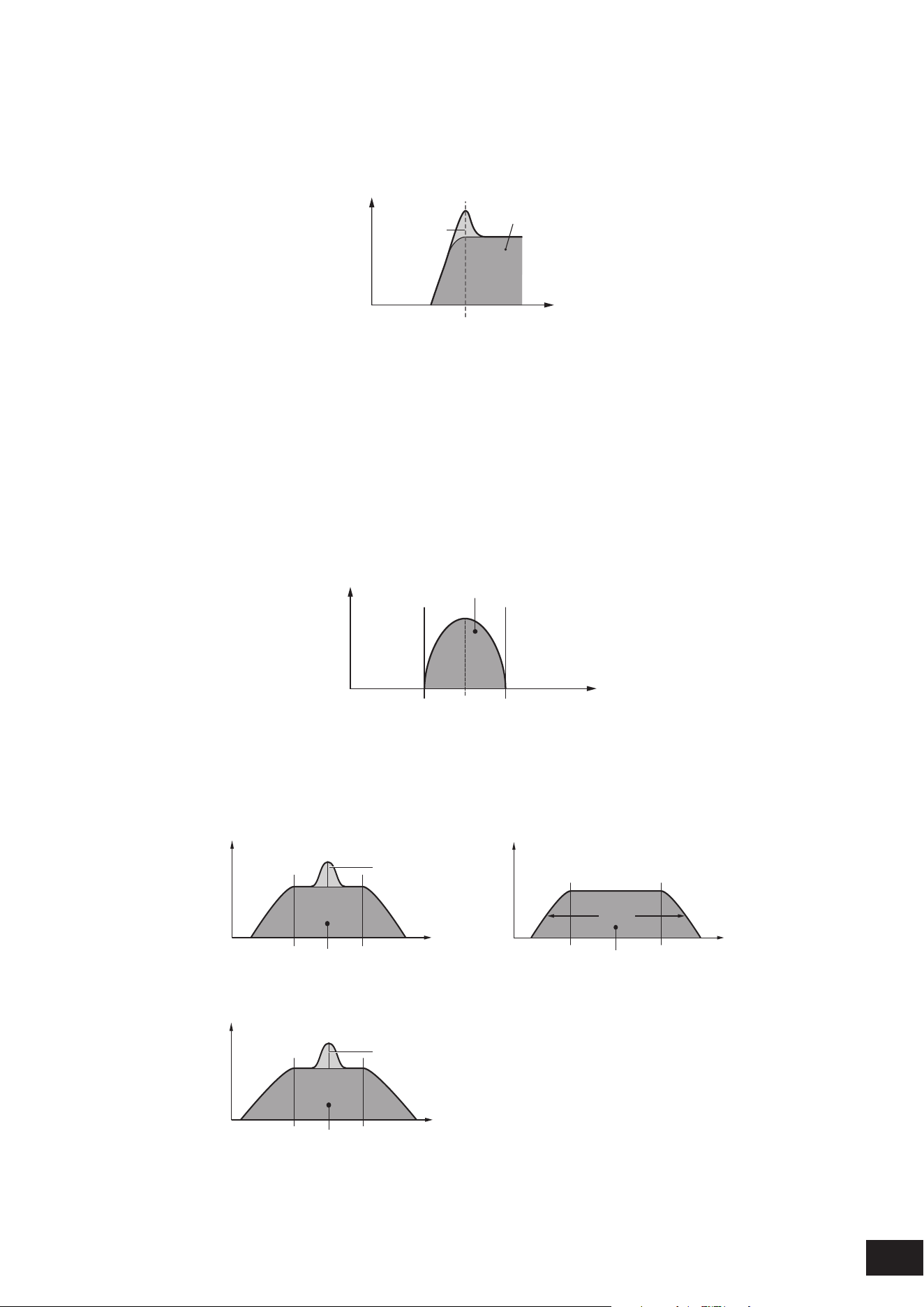
250
MODX M Operation Manual
• HPF (High Pass Filter)
A Filter Type that only passes signals above the Cutoff Frequency.
You can produce a distinctive “peaky” sound by raising the Resonance or boosting the signal level near the Cutoff
Frequency.
Resonance
Frequencies that are
“passed” by the filter
Frequency
Cutoff Frequency
Gain
LPF12+HPF12: A combination of a 2-pole (−12dB/oct) LPF and HPF connected in serial. When this Filter Type is selected, HPF
Cutoff (HPF Cutoff Frequency) and HPF Cutoff /Key (HPF Cutoff Key Follow Sensitivity) can be set
LPF6+HPF12: A combination of a −6dB/oct LPF and a −12dB/oct connected in serial. When this Filter Type is selected, H PF
Cutoff (HPF Cutoff Frequency) and HPF Cutoff /Key (HPF Cutoff Key Follow Sensitivity) can be set
HPF24D: A dynamic −24dB/oct HPF with a characteristic digital sound. This lter can produce a pronounced Resonance
effect.
HPF12: A dynamic −12dB/oct HPF
• BPF (Band Pass Filter)
A Filter Type that only passes signals for a set Cutoff Frequency band and cuts all other signals.
Frequencies that are “passed” by the filter
FrequencyCenter Frequency
Gain
BPF12D: The combination of a −12dB/oct HPF and LPF with a characteristic digital sound
BPFw: The combination of a −12dB/oct HPF and LPF. Allow wider bandwidth settings
BPF6: The combination of a −6dB/oct HPF and LPF
BPF12D BPFw
Width
Frequencies that are
“passed” by the filter
Frequencies that are
“passed” by the filter
Frequencies that are
“passed” by the filter
Frequency Frequency
Frequency
Resonance
Resonance
Gain
Gain
Gain
BPF6
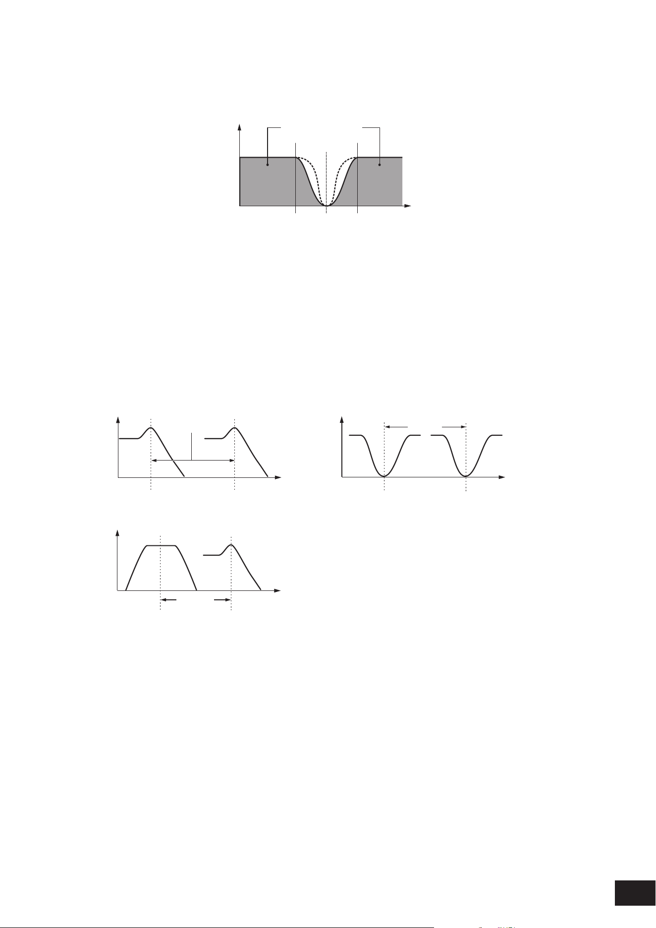
251
MODX M Operation Manual
• BEF (Band Eliminate Filter)
Has an opposite effect on the sound compared to the BPF (Band Pass Filter). A Filter Type that cuts off signals
near the set Cutoff Frequency and passes signals in other frequency bands.
Frequencies that are
“passed” by the filter
Frequency
Center Frequency
Gain
BEF12: −12dB/oct BEF
BEF6: −6dB/oct BEF
DualLPF: Two −12dB/oct LPF connected in parallel. Sets the distance between the Cutoff Frequencies for the two lters
with Distance. The lower limit frequency is set on the screen, and the upper limit frequency is automatically determined in
conjunction
DualHPF: Two −12dB/oct HPF connected in parallel
DualBPF: Two −6dB/oct BPF connected in parallel
DualBEF: Two −6dB/oct BEF connected in serial
LPF12+BPF6: A combination of a −12dB/oct LPF and −6dB/oct BPF connected in parallel. Sets the distance between the
Cutoff Frequencies for the two lters with Distance. The lower limit frequency is set on the screen, and the upper limit frequency
is automatically determined in conjunction
DualLPF DualBEF
Frequency Frequency
Frequency
Distance
Distance
Distance
Gain
Gain
Gain
Cutoff (Filter Cutoff Frequency)
Sets the cutoff frequency.
The frequency set here is used by the lter set in Type.
Settings: 0–1023
Cutoff/Vel (Filter Cutoff Velocity Sensitivity)
Sets how Cutoff Frequency responds to Velocity or the strength of the keystroke.
Settings: −64–+0–+63
Positive value: The faster the Velocity, the higher the Cutoff Frequency value
0: Cutoff frequency does not respond to the Velocity.
Negative value: The slower the Velocity, the higher the Cutoff Frequency value
LPF12+BPF6

252
MODX M Operation Manual
Resonance (Filter Resonance)
Width (Filter Width)
The parameter shown here varies depending on the Filter Type setting. Resonance is shown for LPF, HPF, BPF (excluding
BPFw), or BEF, and Width is shown for BPFw.
For Resonance, this parameter indicates the strength of resonance. This can be used in combination with the Cutoff
parameter to add further character to the sound.
For the BPFw, Width is used for adjusting the width of the frequencies passed by the lter.
Settings: 0–127
Res/Vel (Filter Resonance Velocity Sensitivity)
Sets how the resonance level responds to Velocity or the strength of the keystroke.
This parameter may not be available depending on the Filter Type.
Settings: −64–+0–+63
Positive value: The higher the Velocity, the greater the Resonance becomes
0: Resonance value does not change in response to Velocity.
Negative value: The lower the Velocity, the greater the Resonance becomes
Cutoff/Key (Filter Cutoff Key Follow Sensitivity)
Sets how the cutoff frequency level of the lter responds to the key position.
The reference point is the Cutoff Frequency for the key set in Center Key (FEG Time Key Follow Sensitivity Center Key).
Settings: −200%–0%–+200%
Positive value: The lower the key played, the lower the Cutoff Frequency becomes; the higher the key played, the higher the
Cutoff Frequency becomes
Negative value: The lower the key played, the higher the Cutoff Frequency becomes; the higher the key played, the lower the
Cutoff Frequency becomes
Distance
Sets the distance between the Cutoff Frequencies for the Dual Filter types and the LPF12+BPF6 lter.
This parameter may not be available depending on the Filter Type.
Settings: −128–+0 –+127
HPF Cutoff (HPF Cutoff Frequency)
Sets the center frequency for the functions that control the lter cutoff and how fast the FEG changes according to the key
follow setting of the HPF.
Increasing the value results in a higher Cutoff Frequency, and the low frequency signals are cut or blocked to make
the sound brighter. Decreasing the value results in a lower Cutoff Frequency, allowing more bass components to pass
through to make the sound richer and deeper.
This parameter is not available when the Filter Type is set to LPF12+HPF12 or LPF6+HPF12.
Settings: 0–1023
HPF Cutoff/Key (HPF Cutoff Key Follow Sensitivity)
Sets the level of the Cutoff Frequency of the HPF according to the position of the key.
This parameter is not available when the Filter Type is set to LPF12+HPF12 or LPF6+HPF12.
Settings: −200%–+0–+200%
Positive value: The lower the key played, the lower the Cutoff Frequency becomes; the higher the key played, the higher the
Cutoff Frequency becomes
Negative value: The lower the key played, the higher the Cutoff Frequency becomes; the higher the key played, the lower the
Cutoff Frequency becomes
Gain (Filter Gain)
Sets the Gain (signals sent to the Filter unit).
Lowering the value decreases the volume of the Element.
Settings: 0–255
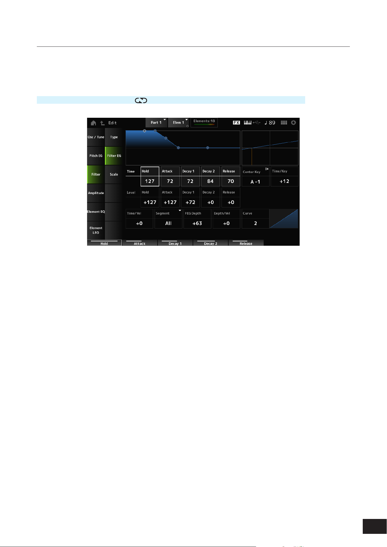
253
MODX M Operation Manual
Filter EG
On the Filter EG screen, you can set the Filter Envelope Generator (FEG) for the Element.
The FEG lets you set the degree (or level) of changes to the Cutoff Frequency and how those changes evolve over time,
starting from the moment you press a key on the keyboard to the moment the sound decays.
Operation
[PERFORMANCE (HOME)]
→
[EDIT/ ]
→
Part selection
→
Element selection
→
Filter
→
Filter EG
Hold Time (FEG Hold Time)
Sets the length of time it takes for maintaining the Cutoff Frequency at Hold Level (FEG Hold Level) starting from the
moment you press a key on the keyboard.
Settings: 0–127
Attack Time (FEG Attack Time)
Sets the length of time it takes for the Cutoff Frequency to change from the end of Hold Time (FEG Hold Time) to the
Attack Level (FEG Attack Level).
Settings: 0–127
Decay 1 Time (FEG Decay 1 Time)
Sets the length of time it takes for the Cutoff Frequency to change from the Attack Level (FEG Attack Level) to the Decay1
Level (FEG Decay 1 Level).
Settings: 0–127
Decay 2 Time (FEG Decay 2 Time)
Sets the length of time it takes for the Cutoff Frequency to change from the Decay 1 Level (FEG Decay 1 Level) to the
Decay 2 Level (FEG Decay 2 Level).
Settings: 0–127
Release Time (FEG Release Time)
Sets the length of time it takes for the Cutoff Frequency to change from the moment you release your nger from the key
until it reaches the Release Level (FEG Release Level).
Settings: 0–127
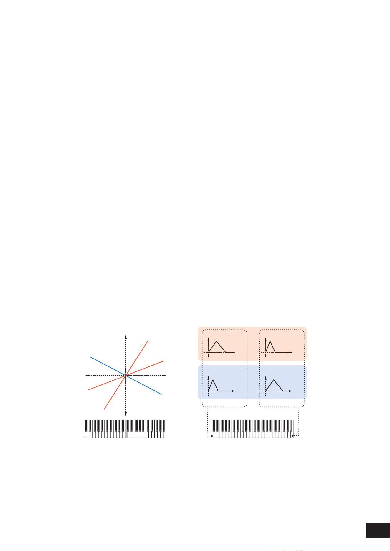
254
MODX M Operation Manual
Hold Level (FEG Hold Level)
Sets the Cutoff Frequency at the moment you press the key.
Settings: −128–+0 –+127
Attack Level (FEG Attack Level)
Sets the Cutoff Frequency value to change after you press the key.
Settings: −128–+0 –+127
Decay 1 Level (FEG Decay 1 Level)
Sets the next Cutoff Frequency value to change from the Attack Level (FEG Attack Level).
Settings: −128–+0 –+127
Decay 2 Level (FEG Decay 2 Level)
Sets the Cutoff Frequency that is maintained while the key is held down.
Settings: −128–+0 –+127
Release Level (FEG Release Level)
Sets the next Cutoff Frequency value after you release your nger from the key.
Settings: −128–+0 –+127
Center Key (FEG Time Key Follow Sensitivity Center Key)
Sets the reference key (note) for Time/Key.
With the key (note) set here, the speed of change in the cutoff frequency set in FEG is used as is.
Settings: C−2–G8
Time/Key (FEG Time Key Follow Sensitivity)
Sets the degree to which the speed of change in the cutoff frequency caused by FEG increases or decreases depending
on the pitch of the key.
The change speed in FEG is used for the specied key in Center Key.
Settings: −64–+63
Positive value: The lower the key played, the slower the change in Cutoff Frequency controlled by the FEG becomes; the
higher the key played, the faster the change becomes
0: No changes to the FEG regardless of the key position
Negative value: The lower the key played, the faster the change in Cutoff Frequency controlled by the FEG becomes; the
higher the key played, the slower the change becomes
Center Key and Time/key
(2)
(1)
(3)
High
Fast
Slow
+63
+30
−40
Low
Time
(6)
Time
(6)
Time
(6)
Time
(6)
(4)
(5)
Low key High key
(1) Key
(2) Speed of the Cutoff Frequency by the FEG
(3) Center Key
(4) When Time/Key is positive
(5) When Time/Key is negative
(6) Cutoff Frequency
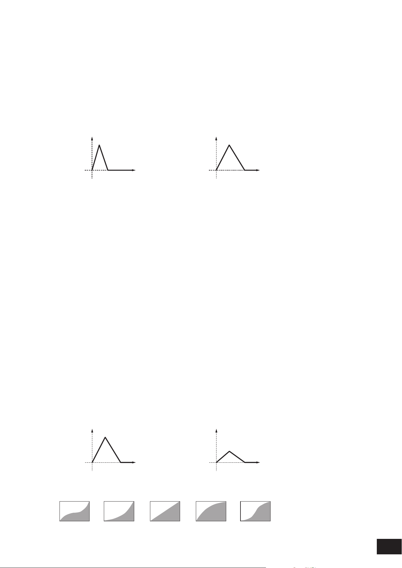
255
MODX M Operation Manual
Time/Vel (FEG Time Velocity Sensitivity)
Segment (FEG Time Velocity Sensitivity Segment)
Sets how the Cutoff Frequency responds to Velocity or the strength of the keystroke.
First, set the time value in Segment, and then the velocity sensitivity value in Time/Vel.
Settings: Time/Vel: −64–+0–+63
Positive value: The faster the Velocity, the faster the change in the Cutoff Velocity by the FEG; the slower the Velocity, the
slower the change
0: No changes regardless of the Velocity setting.
Negative value: The faster the Velocity, the slower the change in the Cutoff Velocity by the FEG; the slower the Velocity, the
faster the change
When the value is positive
Fast Velocity (fast change in Cutoff Frequency) Slow Velocity (slow change in Cutoff Frequency)
Time
(1)
Time
(1)
(1) Cutoff Frequency
Settings: Segment: Attack, Atk+Dcy, Decay, Atk+Rls, All
Attack: The Time/Vel value affects the Attack Time
Atk+Dcy: The Time/Vel value affects the Attack Time and Decay1Time
Decay: The Time/Vel value affects the Decay Time
Atk+Rls: The Time/Vel value affects the Attack Time and Release Time
All: The Time/Vel value affects the time-related settings in FEG
FEG Depth
Sets the depth range for the cutoff frequency change controlled by the FEG. The depth range of the Cutoff Frequency
change becomes wider the further the setting is from a value of 0.
Settings: −64–+0–+63
0: No changes for the Cutoff Frequency by the FEG
Negative value: Cutoff frequency changes are reversed.
Depth/Vel (FEG Depth Velocity Sensitivity)
Curve (FEG Depth Velocity Sensitivity Curve)
Depth/Vel (FEG Depth Velocity Sensitivity) sets how the depth range of the Cutoff Frequency change controlled by the
FEG responds to Velocity or the strength of the keystroke.
With the Curve (FEG Depth Velocity Sensitivity Curve) setting, you can set how the FEG Depth responds to the Velocity.
The vertical axis represents the velocity while the horizontal axis represents the depth range of the Cutoff Frequency
change.
Settings: Depth/Vel: −64–+0–+63
Positive value: The faster the Velocity, the wider the depth range in Cutoff Frequency change by the FEG; the slower the
Velocity, the narrower the depth range
0: Cutoff frequency does not respond to the Velocity.
Negative value: The faster the Velocity, the narrower the depth range in Cutoff Frequency change by the FEG; the slower the
Velocity, the wider the depth range
When the value is positive
Fast Velocity (the depth range in Cutoff Frequency
change is wider)
Slow Velocity (the depth range in Cutoff Frequency
change is narrower)
Time
(1)
Time
(1)
(1) Depth range in Cutoff Frequency change
Settings: Curve: 0–4
0 31 42
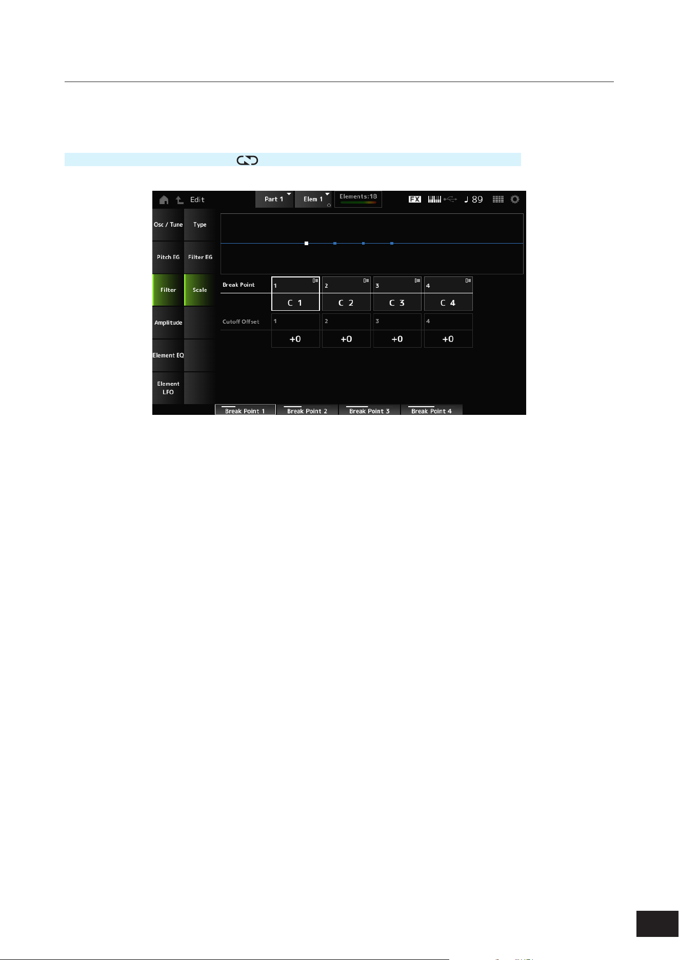
256
MODX M Operation Manual
Scale
On the Scale screen, you can set the lter scale for the Element.
The Filter Scale function allows you to change the Cutoff Frequency of the lter depending on the pitch.
Operation
[PERFORMANCE (HOME)]
→
[EDIT/ ]
→
Part selection
→
Element selection
→
Filter
→
Scale
Break Point (Filter Cutoff Scaling Break Point) 1–4
Sets the note numbers of four points to be set to Cutoff Offset.
Settings: C−2–G8
NOTE
The note numbers for Break Point 1 to 4 will be automatically arranged in ascending order.
Cutoff Offset (Filter Cutoff Scaling Offset) 1–4
Sets the value that increases or decreases the Cutoff on Break Point (Filter Cutoff Scaling Break Point) 1–4.
Settings: −128–+0 –+127
NOTE
• When the offset value is set above or below the Cutoff value, the Cutoff Frequency never goes beyond the settings.
• For any notes below Break Point 1, the value will be set to the Cutoff Frequency of 1. For any notes above Break Point 4, the value will
be set to the Cutoff Frequency of 4.
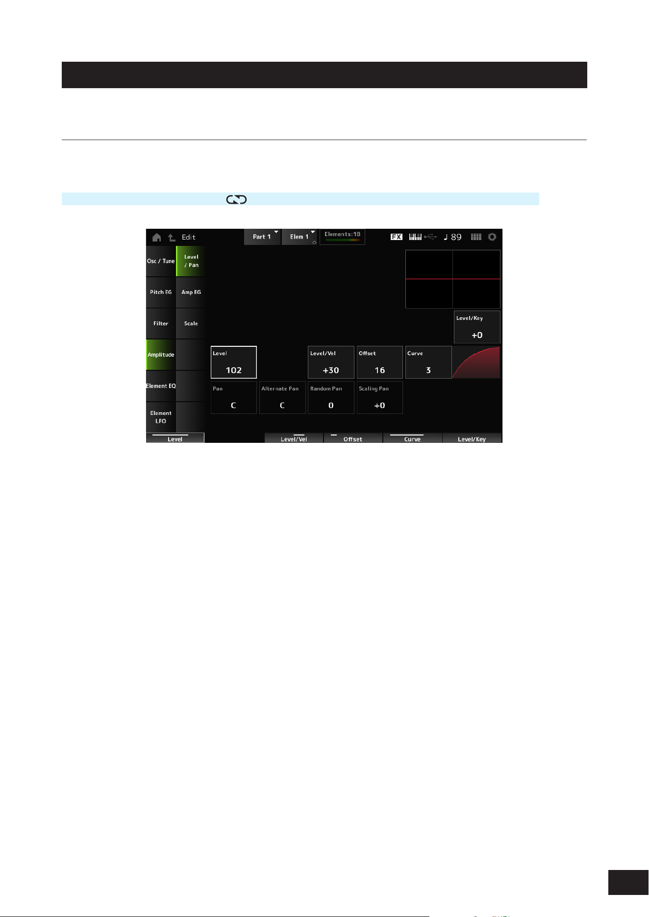
257
MODX M Operation Manual
Amplitude
Level/Pan
On the Level/Pan screen, you can set Level and Pan (position in the stereo eld) for each Element.
Operation
[PERFORMANCE (HOME)]
→
[EDIT/ ]
→
Part selection
→
Element selection
→
Amplitude
→
Level/Pan
Level/Key (Level Key Follow Sensitivity)
Sets how the volume of each Element responds to key position.
The reference point is the volume specied in Center Key (AEG Time Key Follow Center Key).
Settings: −64–+0–+63
Positive value: The lower the key played, the softer the volume becomes; the higher the played, the louder the volume
becomes.
Negative value: The lower the key played, the louder the volume becomes; the higher the played, the softer the volume
becomes.
Level (Element Level)
Sets the output level (volume) for each Element.
Settings: 0–127
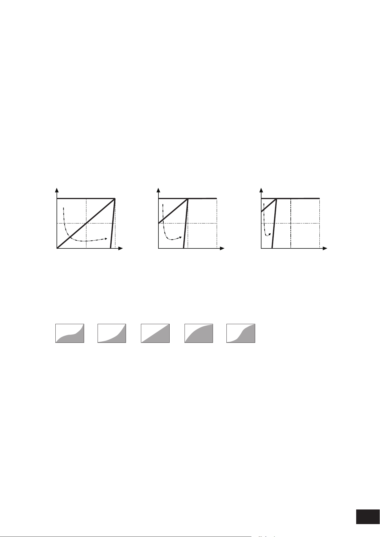
258
MODX M Operation Manual
Level/Vel (Level Velocity Sensitivity)
Offset (Level Velocity Offset)
Curve (Level Sensitivity Key Curve)
Level/Vel (Level Velocity Sensitivity) sets how the volume of each Element responds to Velocity or the strength of the
keystroke.
Offset (Level Velocity Offset) adjusts all settings specied in Level/Vel. When the value exceeds 127, the velocity is set to
12 7.
With the Curve (Level Sensitivity Key Curve) setting, you can set how the volume responds to the Velocity. The vertical
axis represents the velocity while the horizontal axis represents the range for the volume changes.
Settings: Level/Vel: −64–+0–+63
Positive value: The faster the Velocity, the louder the volume becomes
Negative value: The slower the Velocity, the louder the volume becomes
0: No change regardless of the velocity setting.
Settings: Offset: 0–127
Offset = 0 Offset = 64 Offset = 96
0 64 127
127
A
B
X
Y
C
0 64 127
127
A
B
X
Y
C
0 64 127
127
A
B
X
Y
C
A: Level/Vel = 0
B: Level/Vel = 32
C: Level/Vel = 64
X: Velocity with which you play a note
Y: Velocity value sent to the internal tone generator
Settings: Curve: 0–4
0 31 42
Pan (Element Pan)
Sets the Pan position (in the stereo eld) for the Element.
When there are right and left Pan settings for the Elements within a Part, it may be difficult to hear the result of the Pan
setting.
Settings: L63–C (center)–R63

259
MODX M Operation Manual
Alternate Pan (Alternate Pan Depth)
Sets how the sound is panned alternately left and right for each key played.
The value set in Pan (Element Pan) is the center position for the right and left movement of the Pan.
Settings: L63–C (Center)–R63
Random Pan (Random Pan Depth)
Sets how the sound is panned randomly left and right for each key played.
The value set in Pan (Element Pan) is the center position in the stereo eld.
Settings: 0–127
Scaling Pan (Scaling Pan Depth)
Sets how the position of the key you press affects the position of the Pan setting.
The value set in Pan (Element Pan) is the position for C3.
Settings: −64–+0–+63
Positive value: Pan position is scaled to the left for lower keys and to the right for higher keys.
Negative value: Pan position is scaled to the right for lower keys and to the left for higher keys.
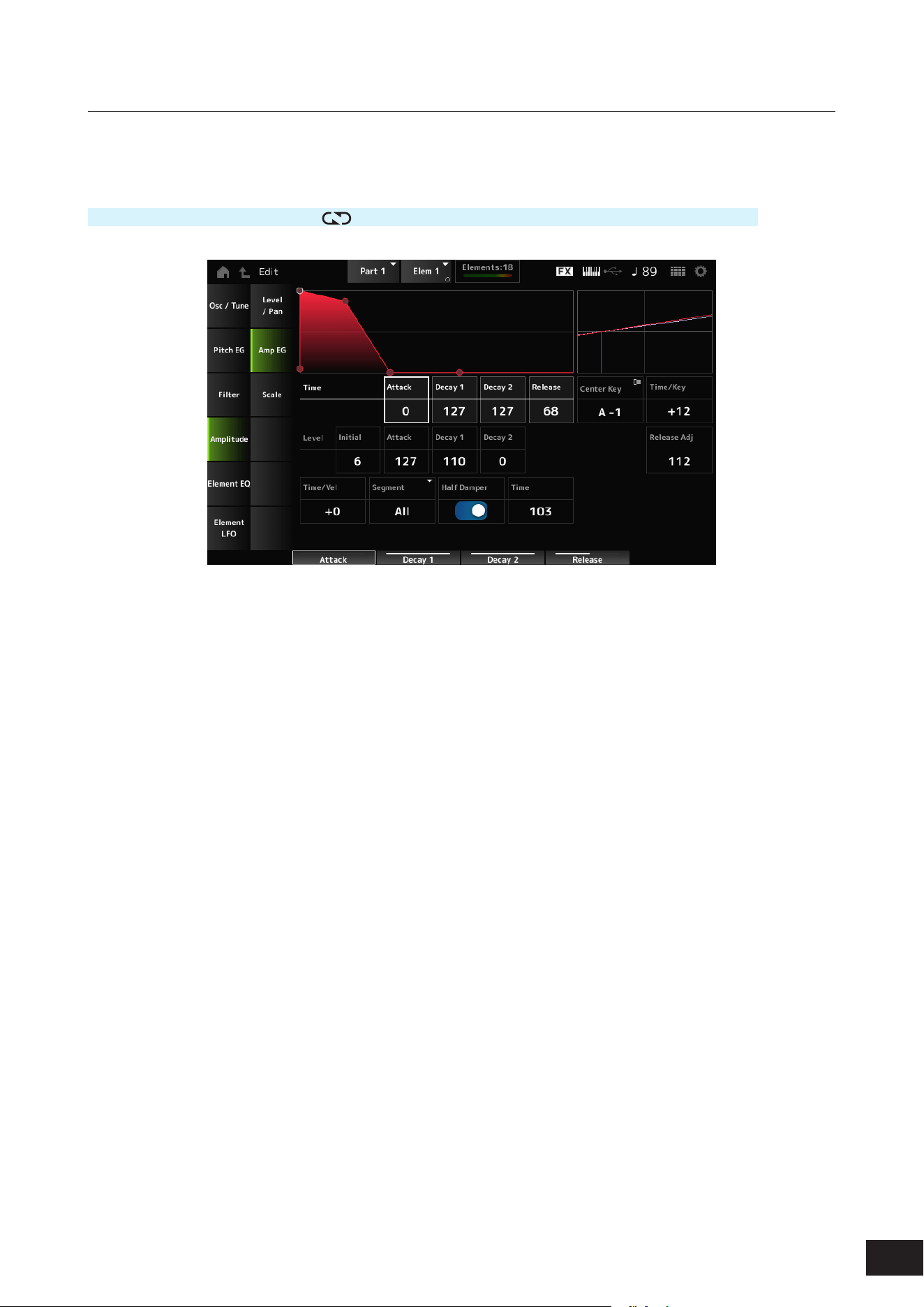
260
MODX M Operation Manual
Amp EG
On the Amp EG screen, you can set the AEG (Amplitude Envelope Generator) for the Element. By setting the Amp EG,
you can set how the volume changes from the moment you press a key on the keyboard to when the sound decays.
Operation
[PERFORMANCE (HOME)]
→
[EDIT/ ]
→
Part selection
→
Element selection
→
Amplitude
→
Amp EG
Attack Time (AEG Attack Time)
Sets the length of time it takes for the volume to change from the moment you press a key on the keyboard until the time
the volume reaches the value set at the Attack Level (AEG Attack Level).
Settings: 0–127
Decay 1 Time (AEG Decay 1 Time)
Sets the length of time it takes for the volume to change from the Attack Level (AEG Attack Level) to the Decay 1 Level
(AEG Decay 1 Level).
Settings: 0–127
Decay 2 Time (AEG Decay 2 Time)
Sets the length of time it takes for the volume to change from the Decay 1 Level (AEG Decay 1 Level) to the Decay 2 Level
(AEG Decay 2 Level).
Settings: 0–127
Release Time (AEG Release Time)
Sets the length of time it takes for the sound to decay after you have released the key.
Settings: 0–127
Initial Level (AEG Initial Level)
Sets the volume for the moment you press the key.
Settings: 0–127
Attack Level (AEG Attack Level)
Sets the volume for changing after you have pressed a key.
Settings: 0–127
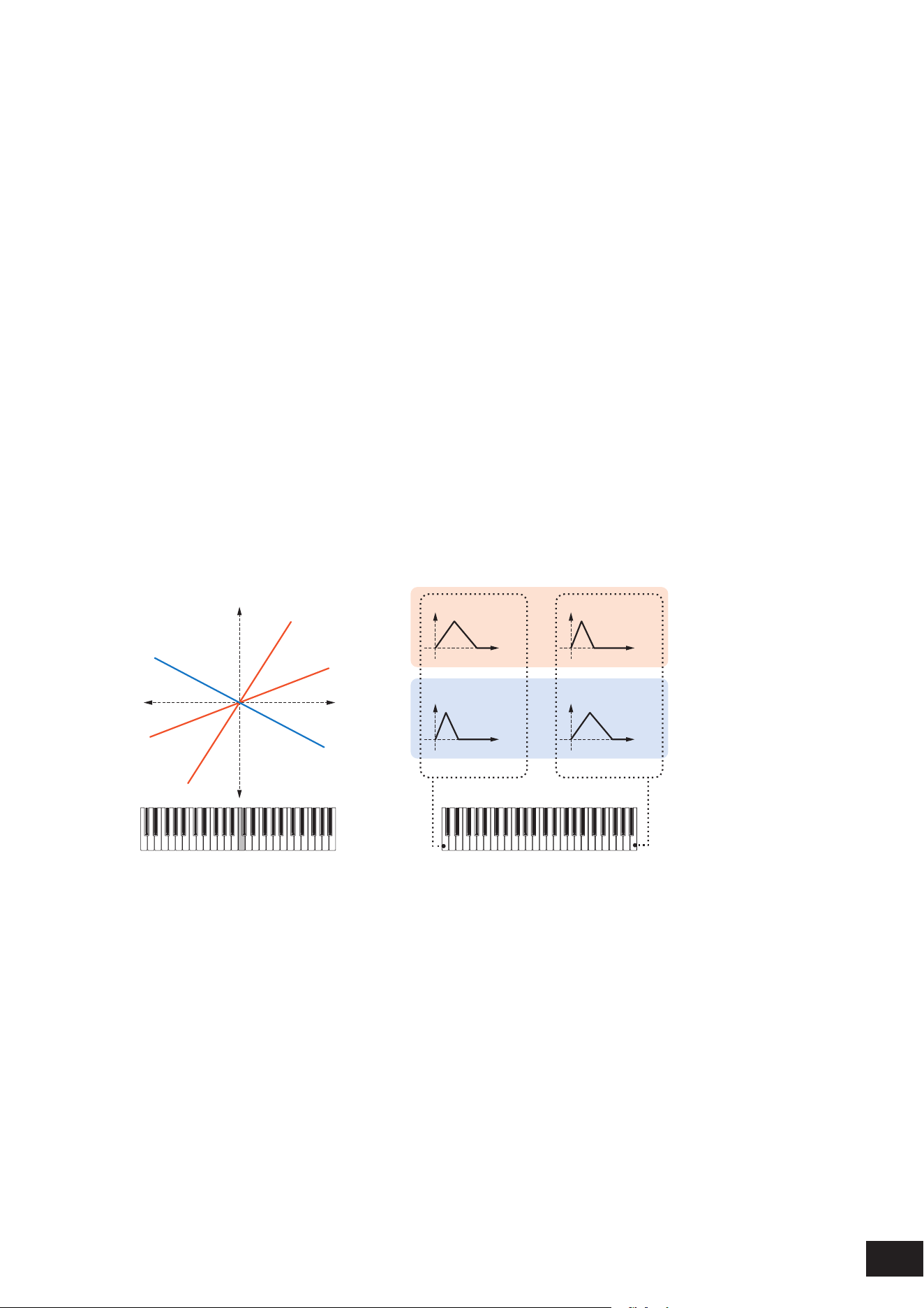
261
MODX M Operation Manual
Decay 1 Level (AEG Decay 1 Level)
Sets the next volume value to change from the Attack Level (AEG Attack Level).
Settings: 0–127
Decay 2 Level (AEG Decay 2 Level)
Sets the volume that is maintained while the key is held down.
Settings: 0–127
Center Key (AEG Time Key Follow Center Key)
Sets the reference key (note) for Time/Key (AEG Time Key Follow Sensitivity).
With the note (key) set here, the resulting sound of the pitch change set in Time/Key (AEG Time Key Follow Sensitivity) is
played.
Settings: C−2–G8
Time/Key (AEG Time Key Follow Sensitivity)
Sets how the speed of the volume changes in AEG responds to key position.
The change speed in AEG is used for the specied key in Center Key (AEG Time Key Follow Center Key).
Settings: −64–+0–+63
Positive value: The lower the key played, the slower the AEG volume changes; the higher the key played, the faster the AEG
volume changes.
0: No AEG volume change regardless of the key position
Negative value: The lower the key played, the faster the AEG volume changes; the higher the key played, the slower the AEG
volume changes.
Center Key and Time/key
(2)
(1)
(3)
High
Fast
Slow
+63
+30
−40
Low
Time
(6)
Time
(6)
Time
(6)
Time
(6)
(4)
(5)
Low key High key
(1) Key
(2) Speed of volume change in AEG
(3) Center Key
(4) When Time/Key is positive
(5) When Time/Key is negative
(6) AEG volume
Release Adj (AEG Time Key Follow Sensitivity Release Adjustment)
Adjusts the sensitivity of the Time/Key (AEG Time Key Follow Sensitivity) to AEG Release.
The lower the value, the lesser the sensitivity.
Settings: 0–127
127: Same Time/Key as Decay 1 and Decay 2
0: The Time/Key does not affect the AEG Release

262
MODX M Operation Manual
Time/Vel (AEG Time Velocity Sensitivity)
Segment (AEG Time Velocity Segment)
Sets the length of time it takes for volume changes in AEG to respond to Velocity or the strength of the keystroke.
First, set the time value in Segment, and then the velocity sensitivity value in Time/Vel.
Settings: Time/Vel: −64–+0–+63
Positive value: The faster the velocity, the faster the AEG volume changes.
0: No changes regardless of the Velocity setting.
Negative value: Fast velocity values result in slower AEG volume changes, while slow velocity values result in faster AEG
volume changes.
When the value is positive
Fast velocity (fast volume change) Slow velocity (slow volume change)
Time
(1)
Time
(1)
(1) Volume
Settings: Segment: Attack, Atk+Dcy, Decay, Atk+Rls, All
Attack: The Time/Vel value affects the Attack Time
Atk+Dcy: The Time/Vel value affects the Attack Time and Decay1Time
Decay: The Time/Vel value affects the Decay Time
Atk+Rls: The Time/Vel value affects the Attack Time and Release Time
All: The Time/Vel value affects the time-related settings in AEG
Half Damper (Half Damper Switch)
By setting this switch On, you can connect a separately sold foot controller FC3A to the [SUSTAIN] jack on the rear panel
and use the half-damper function for your keyboard performance.
The Half-damper function gives you greater expressive control over sound decay, letting you use damper pedal operation
just as you would on an acoustic piano—continuously and not just as an on/off switch.
Settings: Off, On
Time (Half Damper Time)
Sets the time from the moment you have released a key while you are pressing the foot controller FC3A fully down to when
the sound decays when the Half Damper (Half Damper Switch) is set to On. This parameter is not shown when set to Off.
You can adjust the decay time from the Half Damper Time to the Release Time (AEG Release Time) by changing the
amount you press on the pedal.
When you release the pedal, the Release Time (AEG Release Time) is used for decaying sound. By setting the Release
Time to a small value, and Half Damper Time to a large value, you can play a natural decaying sound, like on an acoustic
piano.
Settings: 0–127
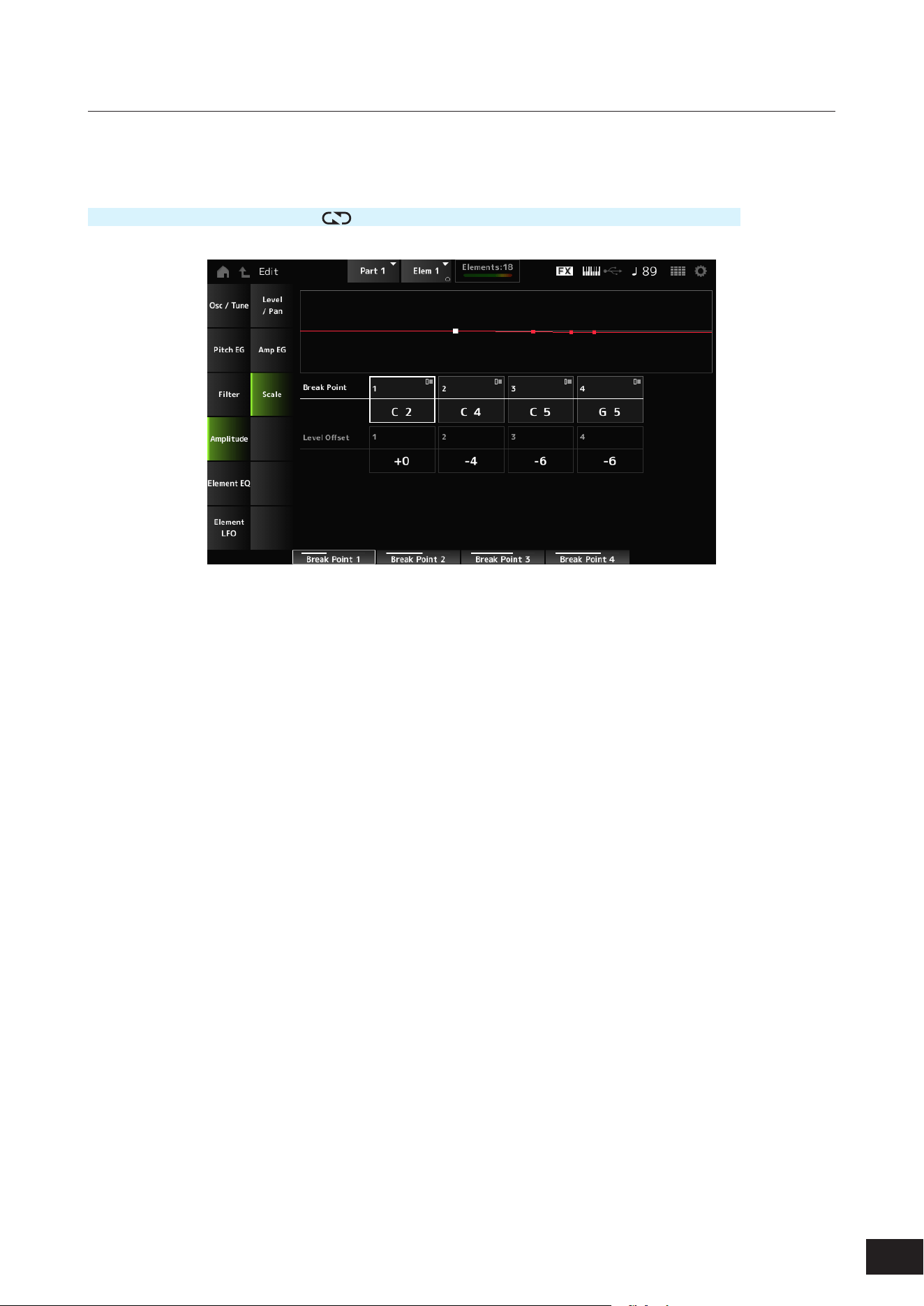
263
MODX M Operation Manual
Scale
On the Scale screen, you can set the Amplitude Scale for the Element.
This changes the volume according to the key position on the keyboard.
Operation
[PERFORMANCE (HOME)]
→
[EDIT/ ]
→
Part selection
→
Element selection
→
Amplitude
→
Scale
Break Point (Level Scaling Break Point) 1–4
Sets the note number for Level Offset (Level Scaling Offset) 1–4.
Settings: C−2–G8
NOTE
The note numbers for Break Point 1 to 4 will be automatically arranged in ascending order.
Level Offset (Level Scaling Offset) 1–4
Sets the value that increases or decreases the Level on Break Point (Level Scaling Break Point) 1–4.
Settings: −128–+0 –+127
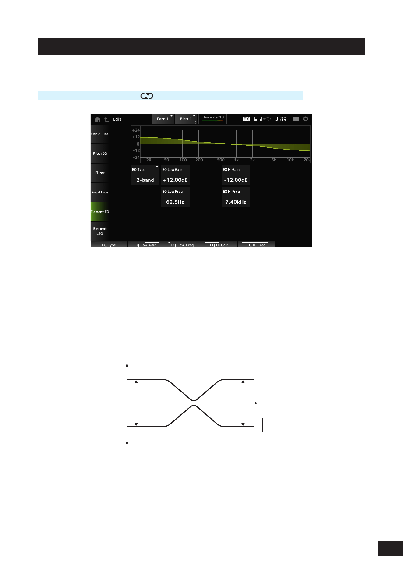
264
MODX M Operation Manual
Element EQ
On the Element EQ screen, you can set the equalizer for the Element.
Operation
[PERFORMANCE (HOME)]
→
[EDIT/ ]
→
Part selection
→
Element selection
→
Element EQ
EQ Type (Element EQ Type)
Selects the desired EQ type.
Settings: 2-band, P.EQ, Boost6, Boost12, Boost18, Thru
2-band: Shelving EQ that boosts or cuts the band of signals above or below a certain frequency (Low Freq or High Freq).
P.EQ: Parametric EQ that boosts or cuts the signal level (Gain)) around the Center Frequency (Freq).
Boost6: Boosts the level by 6 dB.
Boost12: Boosts the level by 12 dB
Boost18: Boosts the level by 18 dB
Thru: Passes the signals with no effects being applied
When EQ Type is set to 2-band
–
+
0
Gain
Low Gain High Gain
Low Freq High Freq
Frequency
EQ Low Gain (Element EQ Low Gain)
Sets the signal level of the Low band.
Settings: −12.00dB – +0.00dB – +12.00dB
EQ Low Freq (Element EQ Low Frequency)
Sets the frequency of the Low band.
Settings: 50.1Hz–2.00kHz

265
MODX M Operation Manual
EQ Hi Gain (Element EQ High Gain)
Sets the signal level of the High band.
Settings: −12.00dB – +0.00dB – +12.00dB
EQ Hi Freq (Element EQ High Frequency)
Sets the frequency of the High band.
Settings: 503.8Hz–10.1kHz
When EQ Type is set to P.EQ
–
+
0
Gain
Gain
Freq
Q
Frequency
EQ Gain (Element EQ Gain)
Sets the signal level for the frequency range set in EQ Freq (Element EQ Frequency).
Settings: −12.00dB – +0.00dB – +12.00dB
EQ Freq (Element EQ Frequency)
Sets the frequency to be cut or boosted.
Settings: 139.7Hz–12.9kHz
EQ Q (Element EQ Q)
By boosting or cutting the signal level of the frequency set in EQ Freq (Element EQ Frequency), you can create various
frequency response curves.
Settings: 0.7–10.3
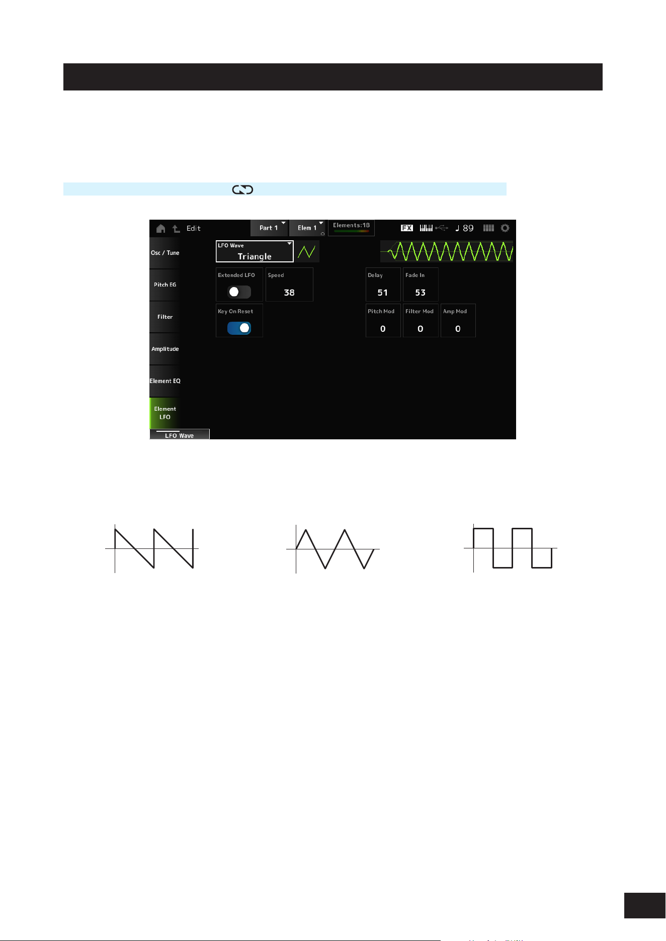
266
MODX M Operation Manual
Element LFO
On the Element LFO screen, you can set the LFO (Low Frequency Oscillator) for the Element.
The LFO (Low Frequency Oscillator) for the Element generates signals in the low band, and you can use it for modulation
(cyclical variation) of the pitch, lter, and amplitude.
Operation
[PERFORMANCE (HOME)]
→
[EDIT/ ]
→
Part selection
→
Element selection
→
Element LFO
LFO Wave
Selects an LFO wave, By using the wave you have selected here, you can create various types of modulation.
Settings: Saw, Triangle, Square
Saw (Sawtooth wave) Triangle (Triangle wave) Square (Square wave)
Extended LFO
Switches between the old set of Speed (LFO Speed) settings (Off: 0–63) and a new set of settings with higher resolution
(On: 0–415) for Speed (LFO Speed).
To maintain compatibility of data created with the old settings, set this parameter to Off.
Settings: Off, On
Speed (LFO Speed)
Sets the speed of LFO Wave changes. The larger the value of this parameter, the faster the speed becomes.
Settings: 0–63 (Extended LFO set to Off), 0–415 (Extended LFO set to On)
Delay (LFO Delay Time)
Sets the delay time between the moment you press a key on the keyboard and the moment the LFO comes into effect.
Settings: 0–127
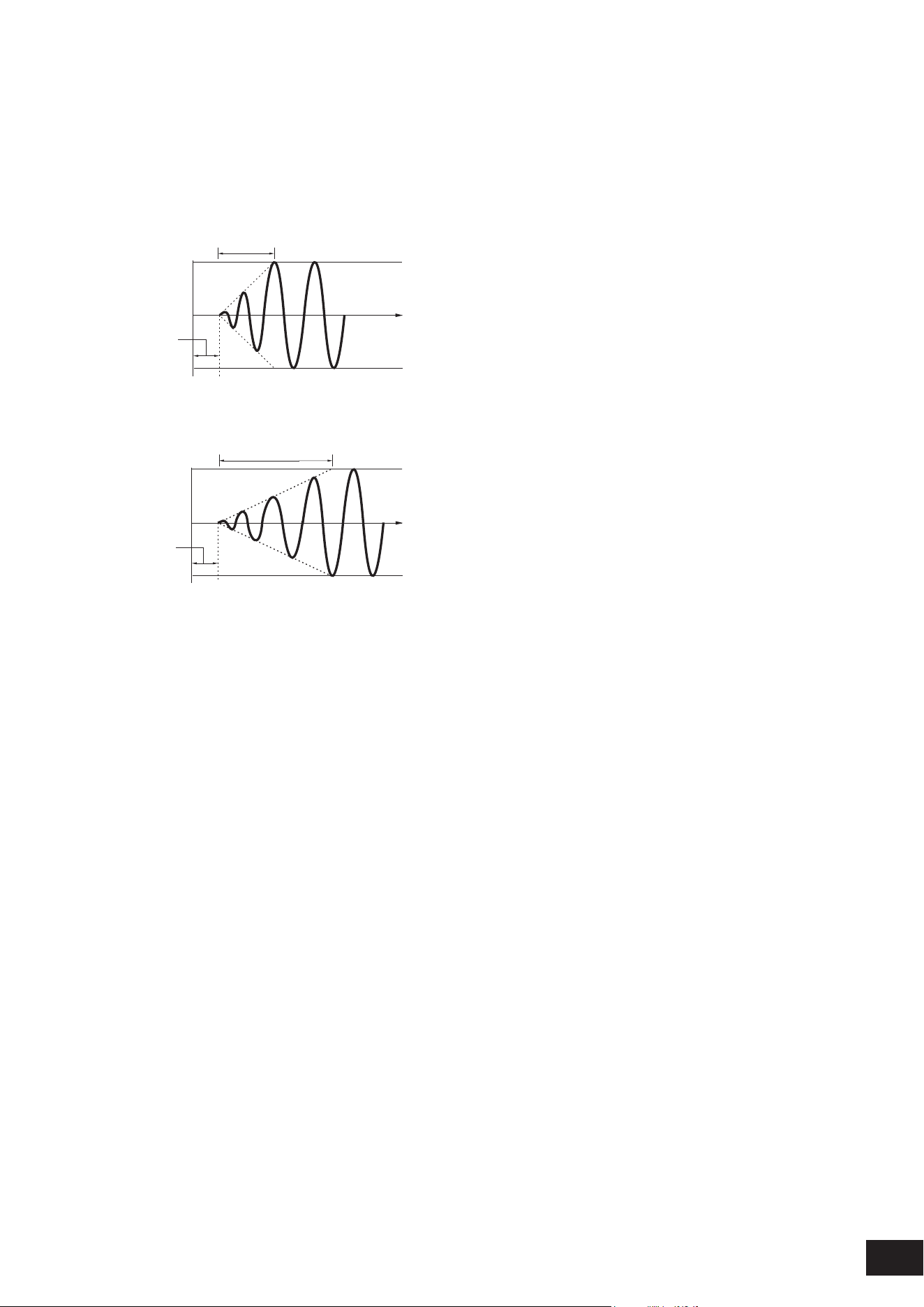
267
MODX M Operation Manual
Fade In (LFO Fade In Time)
Sets the time length for the LFO effect to fade in after you have released the key and the delay time set in Delay (LFO
Delay Time) has elapsed. The larger the value, the longer it takes for the LFO effect to reach the maximum.
Settings: 0–127
0: The LFO changes to the maximum value without any fade-ins.
When the value is small
Fade In
Maximum
Delay
Key On
Time
When the value is large
Fade In
Maximum
Delay
Key On
Time
Key On Reset (LFO Key On Reset)
Resets the oscillation of the LFO when a key is pressed.
Settings: Off, On
Pitch Mod (LFO Pitch Modulation Depth)
This parameter creates a vibrato effect (cyclical changes to the pitch) by using LFO waves.
Setting the parameter to larger values results in greater change to the volume.
Settings: 0–127
Filter Mod (LFO Filter Modulation Depth)
This parameter creates a wah effect (cyclical changes to the lter cutoff frequency) by using LFO waves.
Larger values result in greater range for cutoff frequency changes.
Settings: 0–127
Amp Mod (LFO Amplitude Modulation Depth)
This parameter creates a tremolo effect (cyclical changes in the volume) by using LFO waves.
Setting the parameter to larger values results in greater change to the volume.
Settings: 0–127
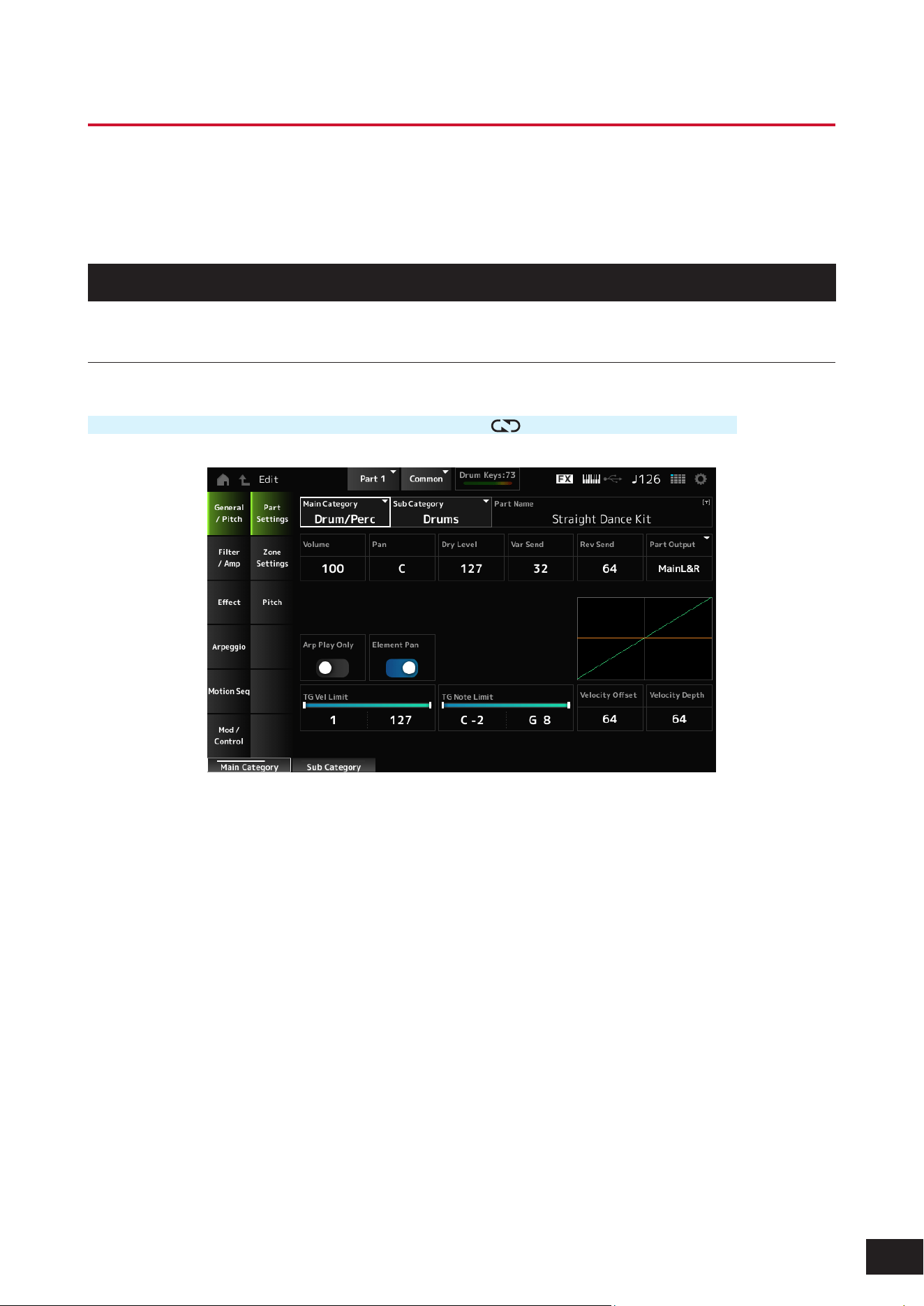
268
MODX M Operation Manual
Drum Part Edit (AWM2) Part Common Edit Screens
The Drum Part (AWM2) consists of 73 drum keys.
Drum Part Edit (AWM2) includes Part Common Edit (for setting parameters for the entire Part) and Key Edit (for setting
parameters for individual drum keys).
General/Pitch
Part Settings
Operation
[PERFORMANCE (HOME)]
→
Part Common selection
→
[EDIT/ ]
→
General/Pitch
→
Part Settings
Main Category (Part Main Category)
Sub Category (Part Sub Category)
Sets the Main category and Sub category of the selected Part.
Settings: Refer to the Data List
Part Name
You can save the Part you are editing under a new name, You can use up to 20 alphanumeric characters.
Volume
Sets the volume of the selected Part.
Settings: 0–127
Pan
Adjusts the Pan position (in the stereo eld) of the selected Part.
Settings: L63–C (center)–R63

269
MODX M Operation Manual
Dry Level
Sets the Dry Level of the selected Part.
This parameter is available only when Part Output (Part Output Select) is set to MainL&R or Drum.
Settings: 0–127
Var Send (Variation Send)
Sets the Variation Send of the selected Part.
This parameter is available only when Part Output (Part Output Select) is set to MainL&R or Drum.
Settings: 0–127
Rev Send (Reverb Send)
Sets the Reverb Send of the selected Part.
This parameter is available only when Part Output (Part Output Select) is set to MainL&R or Drum.
Settings: 0–127
Part Output (Part Output Select)
Sets the output destination for the audio signals of the selected Part.
Settings: MainL&R, (AsgnL&R), USB Stereo, (AsgnL), (AsgnR), USB mono, Off, Drum
MainL&R: Outputs in stereo (two channels) to the OUTPUT [L/MONO] and OUTPUT [R] jacks.
USB Stereo: Outputs in stereo (channels 1 and 2, to channels 7 and 8) to the USB [TO HOST] terminal
USB mono: Outputs in mono (channels 1 to 8) to the USB [TO HOST] terminal
Off: No output of the audio signal for the Part.
Drum: You can set the output for each drum key.
NOTE
The settings for data compatibility with MONTAGE M are shown below. They are considered Off when set.
• AsgnL&R
• USB Stereo: USB9&10 – USB29&30
• USB mono: USB9 – USB30
• AsgnL
• AsgnR
Arp Play Only (Arpeggio Play Only)
Sets the Part to be played only with the Arpeggio.
Any Part set to On will be played by the Note On messages sent from the Arpeggio.
Settings: Off, On
Element Pan (Element Pan Switch)
Sets the Pan to On or Off from the Key Edit.
When set to Off, the Pan in the Key Edit will be set to C (center).
Settings: Off, On
Velocity Limit
Sets the velocity range (lowest and highest values) for the Part.
Settings: 1–127
Note Limit
Sets the note range (lowest and highest notes) for the Part.
Settings: C−2–G8
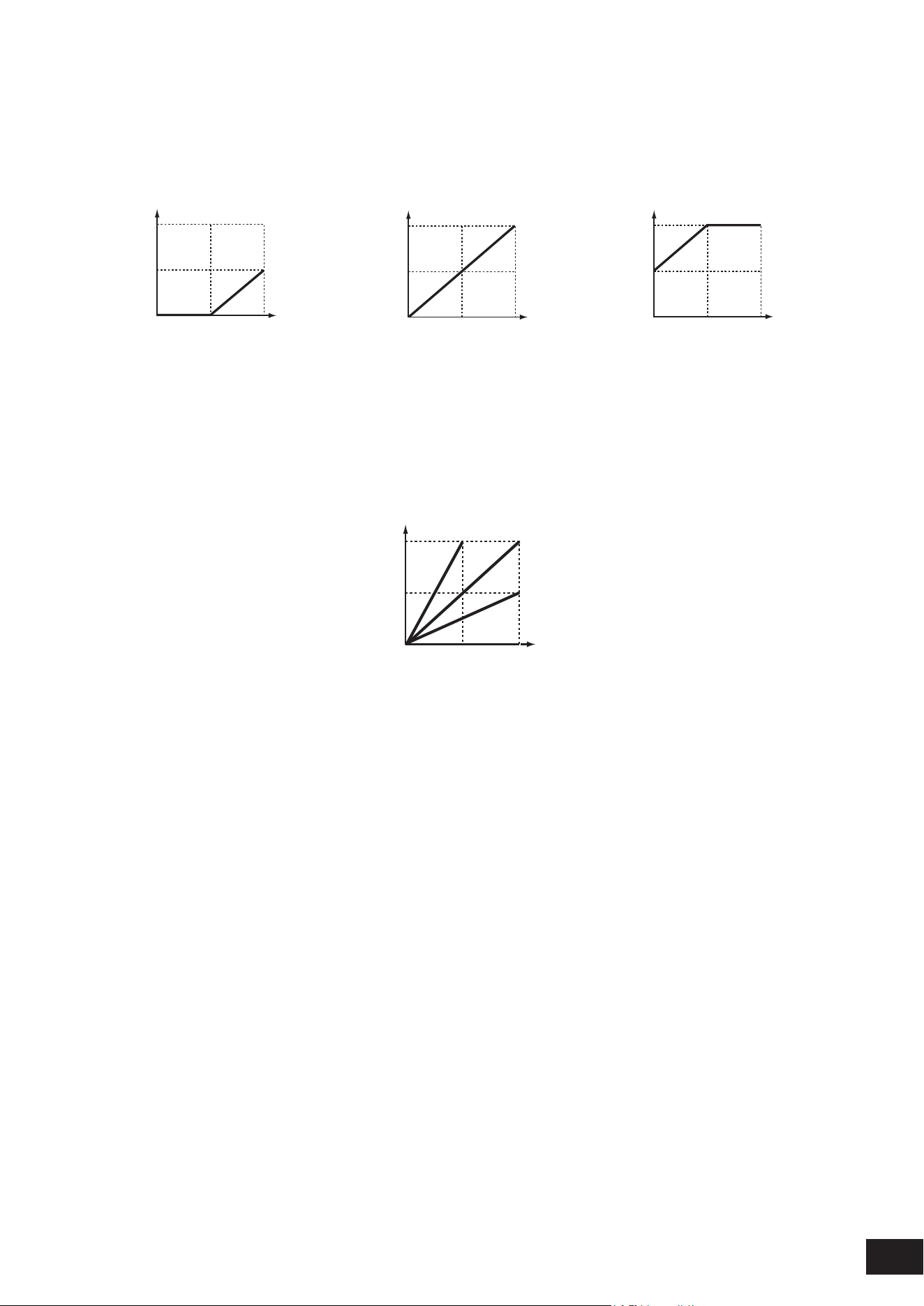
270
MODX M Operation Manual
Velocity Offset (Velocity Sensitivity Offset)
Increases or decreases the velocity value that is sent to the internal tone generator.
Settings: 0–127
When Velocity Depth = 64
and Velocity Offset = 32
When Velocity Depth = 64
and Velocity Offset = 64
When Velocity Depth = 64
and Velocity Offset = 96
127
0 12764
127
64
127
0
12764
127
0
(1)
(2)
(1)
(2)
(1)
(2)
127
0 12764
127
64
127
0
12764
127
0
(1)
(2)
(1)
(2)
(1)
(2)
127
0 12764
127
64
127
0
12764
127
0
(1)
(2)
(1)
(2)
(1)
(2)
(1) Actual resulting velocity (affecting the tone generator)
(2) Velocity with which you play a note
Velocity Depth (Velocity Sensitivity Depth)
Sets how the level of the velocity value (sent to the internal tone generator) responds to Velocity or the strength of the
keystroke.
Settings: 0–127
When Velocity Depth = 64
127
0
12764
(1)
Depth = 127
Depth = 64
Depth = 32
Depth = 0
(2)
(1) Actual resulting velocity (affecting the tone generator)
(2) Velocity with which you play a note
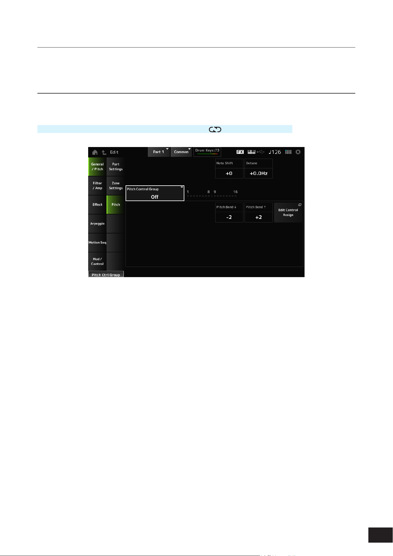
271
MODX M Operation Manual
Zone Settings
The same as General/Pitch
→
Zone Settings on the Part Edit (AWM2) Part Common Edit screen.
Pitch
On the Pitch screen, you can set the pitch for the Part.
Operation
[PERFORMANCE (HOME)]
→
Part Common selection
→
[EDIT/ ]
→
General/Pitch
→
Pitch
Note Shift
Adjusts the pitch in semitones.
Settings: −48–+0–+48
Detune
Adjusts the pitch of the selected Part in 0.1 Hz increments.
By slightly shifting the pitch, you can detune the sound.
Settings: −12.8Hz–+0.0Hz–+12.7Hz
Pitch Control Group
Parts assigned to the same group are given the same pitch.
However, Portamento, Mono/Poly, and Micro Tuning are not available for the Drum Part.
Pitch Bend
(Pitch Bend Range Lower)
Pitch Bend
(Pitch Bend Range Upper)
Sets the range of the changes created with the Pitch Bend wheel in semitones.
Settings: −48–+0–+24

272
MODX M Operation Manual
Filter/Amp
Filter
The same as Filter/Amp
→
Filter on the Part Edit (AWM2) Part Common Edit screen.
Amp EG
The same as Filter/Amp
→
Amp EG on the Part Edit (AWM2) Part Common Edit screen.
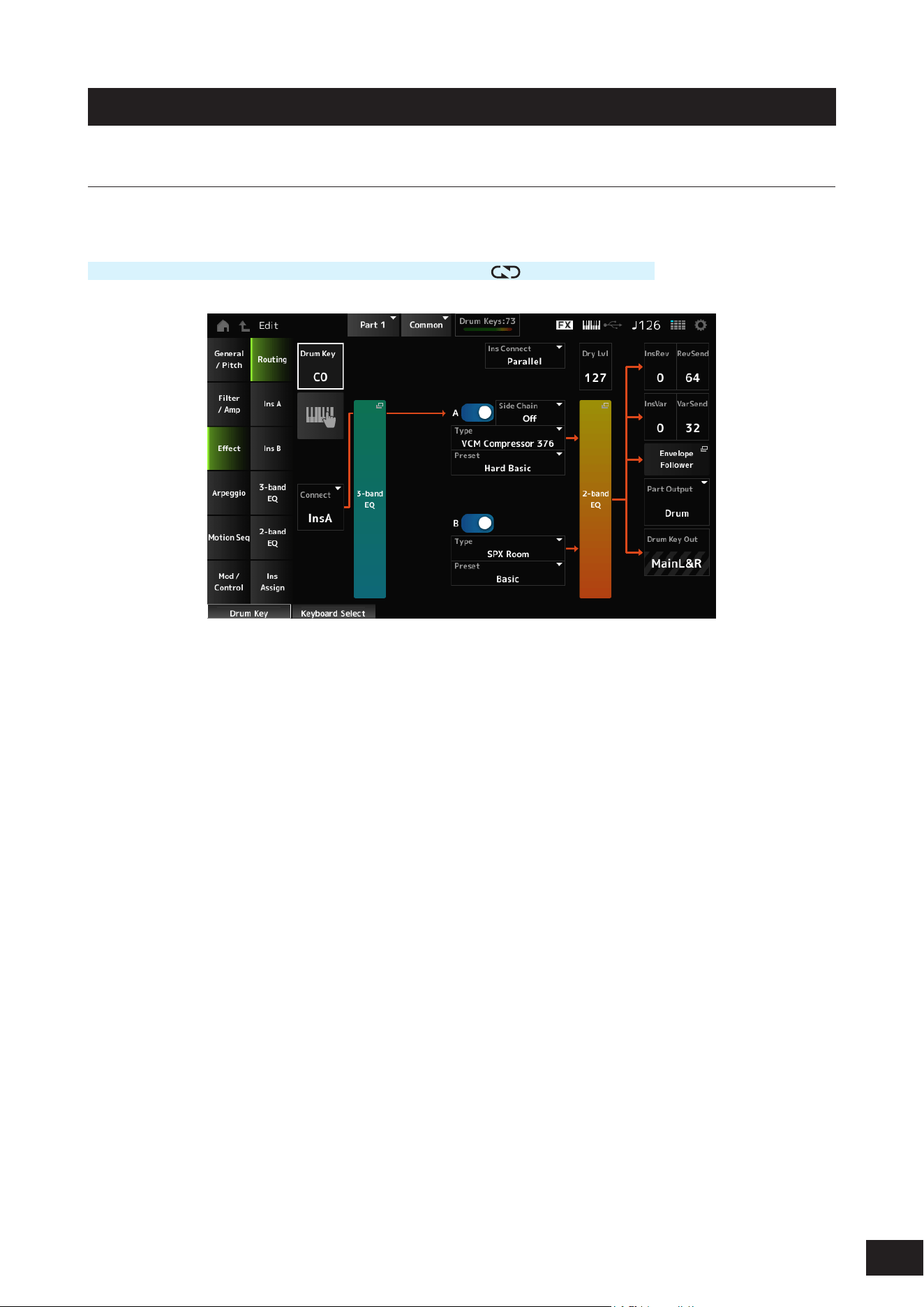
273
MODX M Operation Manual
Effect
Routing
On the Routing screen, you can set the effect routing for the Part.
Operation
[PERFORMANCE (HOME)]
→
Part Common selection
→
[EDIT/ ]
→
Effect
→
Routing
The screen here is basically the same as the one opened from Effect
→
Routing on the Part Edit (AWM2) Part Common
Edit screen; however, the parameters added to Drum Part Edit (AWM2) are shown below.
Drum Key (Drum Key Select)
Shows the name of the selected Drum Key.
Settings: C0–C6
Keyboard Select
Sets the Keyboard select setting on or off.
When this parameter is set to On, you can select the desired drum key for editing by pressing a key on the keyboard.
Settings: Off, On
Connect (Drum Key Connection Switch)
Sets the Key to be output to Insertion Effect A (InsA) or Insertion Effect B (InsB), or bypasses the Insertion Effect (Thru).
Settings: Thru, InsA, InsB

274
MODX M Operation Manual
InsRev (Insertion to Reverb Send Level)
InsVar (Insertion to Variation Send Level)
Sets the level of the Drum Key signals sent to Insertion Effect A or Insertion Effect B to the Reverb or Variation Effect.
This setting is applied to the entire Drum Part (all Drum Keys).
This parameter is available only when Connect (Drum Key Connection Switch) is set to InsA or InsB, and Part Output (Part
Output Select) is set to MainL&R or Drum.
Settings: 0–127
KeyRev (Drum Key Reverb Send Level)
KeyVar (Drum Key Variation Send Level)
Sets the level of the drum key signals sent through Insertion Effect A or Insertion Effect B to the Reverb or Variation Effect.
This parameter can be set to each drum key.
This parameter is available only when Connect (Drum Key Connection Switch) is set to Thru, Part Output (Part Output
Select) and is set to MainL&R, or when Part Output is set to Drum and Drum Key Out is set to MainL&R.
Settings: 0–127
Drum Key Out (Drum Key Output Select)
Sets the output destination for each Drum Key.
This parameter is shown only when Part Output (Part Output Select) is set to Drum.
Settings: MainL&R, (AsgnL&R), USB Stereo, (AsgnL), (AsgnR), USB mono
MainL&R: Outputs in stereo (two channels) to the OUTPUT [L/MONO] and OUTPUT [R] jacks.
USB Stereo: Outputs in stereo (channels 1 and 2, to channels 7 and 8) to the USB [TO HOST] terminal
USB mono: Outputs in mono (channels 1 to 8) to the USB [TO HOST] terminal
NOTE
• The settings for data compatibility with MONTAGE M are shown below. They are considered Off when set.
• AsgnL&R
• USB Stereo: USB9&10 – USB29&30
• USB mono: USB9 – USB30
• AsgnL
• AsgnR
• Connect (Drum Key Connection Switch) is set to InsA/InsB, this parameter is xed to MainL&R.

275
MODX M Operation Manual
Ins A, Ins B
On the Ins A and Ins B screens, you can set the Insertion Effects.
Operation
[PERFORMANCE (HOME)]
→
Part Common selection
→
[EDIT/ ]
→
Effect
→
Ins A
[PERFORMANCE (HOME)]
→
Part Common selection
→
[EDIT/
]
→
Effect
→
Ins B
The same as Audio In
→
Ins A and Ins B on the Common Edit screen.
3-band EQ
The same as Effect
→
3-band EQ on the Part Edit (AWM2) Part Common Edit screen.
2-band EQ
The same as Effect
→
2-band EQ on the Part Edit (AWM2) Part Common Edit screen.
Ins Assign
The same as Effect
→
Ins Assign on the Part Edit (AWM2) Part Common Edit screen.

276
MODX M Operation Manual
Arpeggio
Common
The same as Arpeggio
→
Common on the Part Edit (AWM2) Part Common Edit screen.
Individual
The same as Arpeggio
→
Individual on the Part Edit (AWM2) Part Common Edit screen.
Advanced
The screen here is basically the same as the one opened from Arpeggio
→
Advanced on the Part Edit (AWM2) Part
Common Edit screen; however, the parameter shown below has been added.
Fixed SD/BD (Arpeggio Fixed SD/BD)
When this parameter is set to On, Arpeggio playback uses C1 for the bass drum and D1 for the snare drum.
Most drum kits assign the bass drum to C1 and the snare drum to D1, but some drum kits may assign different notes.
Therefore, depending on the combination of the selected drum kit and Arpeggio Type, it may sound unnatural. Turning this
parameter on may resolve this unnatural sound.
Settings: Off, On

277
MODX M Operation Manual
Motion Seq
Common
The same as Motion Seq
→
Common on the Part Edit (AWM2) Part Common Edit screen.
Lane
The same as Motion Seq
→
Lane on the Part Edit (AWM2) Part Common Edit screen.

278
MODX M Operation Manual
Mod/Control
Control Assign
Other than the Destination setting, the same as Mod/Control
→
Control Assign on the Part Edit (AWM2) Part Common
Edit screen.
For the list of Destination settings, refer to the Control List on the Data List.
Tx /Rx Switch
The same as Mod/Control
→
Tx/Rx Switch on the Part Edit (AWM2) Part Common Edit screen.
Control Settings
The same as Mod/Control
→
Control Settings on the Part Edit (AWM2) Part Common Edit screen.
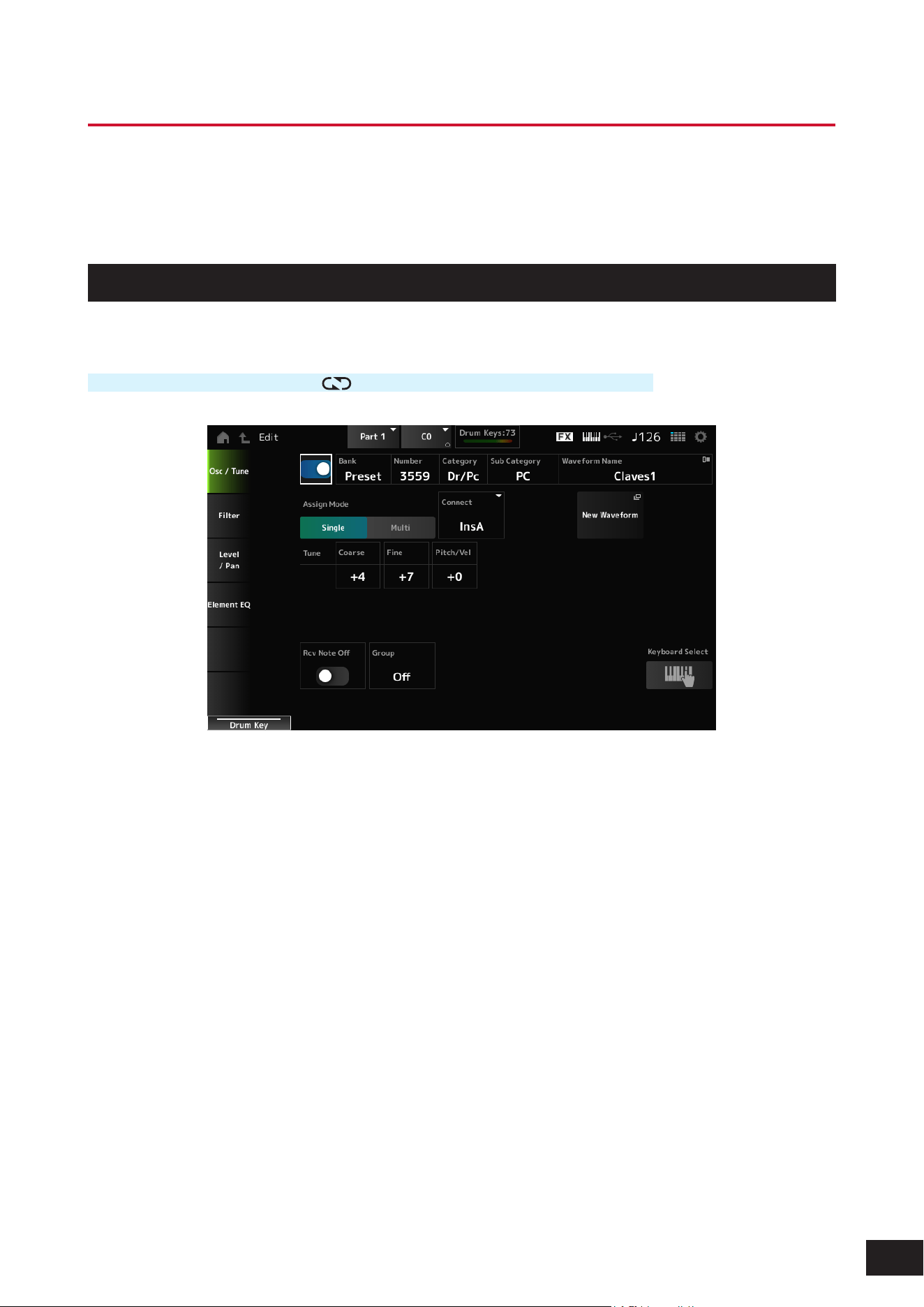
279
MODX M Operation Manual
Drum Part Edit (AWM2) Key Edit screen
The Drum Part (AWM2) consists of 73 drum keys.
Drum Part Edit (AWM2) includes Part Common Edit (for setting parameters for the entire Part) and Key Edit (for setting
parameters for individual drum keys).
Osc/ Tune
On the Osc/Tune screen, you can set the Oscillator for each key within the Drum Part.
Operation
[PERFORMANCE (HOME)]
→
[EDIT/ ]
→
Part selection
→
Key selection
→
Osc/ Tune
Drum Key Switch
Sets the selected Drum Key to use.
Settings: Off, On
Bank (Waveform Bank)
Number (Waveform Number)
Category (Waveform Category)
Sub Category (Waveform Sub Category)
Waveform Name
Shows the name of the Waveform selected for the Drum Key.
Bank indicates the type of Waveform (Preset, User, and Library) assigned to the Element.
Settings: Refer to the Data List

280
MODX M Operation Manual
Assign Mode (Key Assign Mode)
Sets how sound is produced when the internal tone generator receives Note On messages of the same sound twice (or
more) in a row. The Multi setting makes rolls sound natural, especially crash cymbals or other percussion instruments
having a long decay.
Settings: Single, Multi
Single: Stops the rst note and then plays the same note again.
Multi: Plays the second note over the rst note
Connect (Drum Key Connection)
Sets the Key to be output to Insertion Effect A (InsA) or Insertion Effect B (InsB), or bypasses the Insertion Effect (Thru).
This parameter is the same as Effect
→
Routing Connect (Drum Key Connection Switch) on the Drum Part Edit (AWM2)
Part Common Edit screen.
Settings: Thru, InsA, InsB
New Waveform
Loads an audio le saved to USB ash drive as a Waveform.
Edit Waveform appears when a Waveform is loaded.
Edit Waveform
The Waveform Edit screen will open.
Coarse (Coarse Tune)
Shifts the pitch of the waveform assigned to the Drum Key.
Settings: −48–+0–+48
Fine (Fine Tune)
Finely adjusts the pitch of the wave assigned to the Drum Key.
Settings: −64–+0–+63
Pitch/Vel (Pitch Velocity Sensitivity)
Sets how the pitch change responds to Velocity or the strength of the keystroke.
Settings: −64–+0–63
Positive value: The faster the Velocity, the higher the pitch becomes
0: kept unchanged
Negative value: The faster the Velocity, the lower the pitch becomes
Rcv Note Off (Receive Note Off)
Sets the drum key to receive MIDI note-off messages. Set this to On for percussion instrument sounds to make them last
without decay.
Settings: Off, On
On: The sound stops when release the key
Off: The sound decays after you release the key
Group (Alternate Group)
This setting helps you to prevent improper or unnatural combinations of drum keys to be played together.
For example, you can assign open and closed hi-hats to the same Group so that you can avoid them being played
together.
For drum keys that can be played naturally with any combination, set this parameter to Off.
Settings: Off, 1–127

281
MODX M Operation Manual
KeyRev (Drum Key Reverb Send Level)
KeyVar (Drum Key Variation Send Level)
Sets the level of the drum key signals sent through Insertion Effect A or Insertion Effect B to the Reverb or Variation Effect.
This parameter can be set to each drum key.
This parameter is not available depending on the Connect (Drum Key Connection Switch), Part Output (Part Output
Select), and Drum Key Out (Drum Key Output Select) settings.
Settings: 0–127
Drum Key Out (Drum Key Output Select)
Sets the output destination for the Drum Key.
This parameter is not available depending on the Connect (Drum Key Connection Switch) and Part Output (Part Output
Select) settings.
Settings: MainL&R, (AsgnL&R), USB Stereo, (AsgnL), (AsgnR), USB Mono
MainL&R: Outputs in stereo (two channels) to the OUTPUT [L/MONO] and OUTPUT [R] jacks.
USB Stereo: Outputs in stereo (channels 1 and 2, to channels 7 and 8) to the USB [TO HOST] terminal
USB Mono: Outputs in mono (channels 1 to 8) to the USB [TO HOST] terminal
NOTE
The settings for data compatibility with MONTAGE M are shown below. They are considered Off when set.
• AsgnL&R
• USB Stereo: USB9&10 – USB29&30
• USB mono: USB9 – USB30
• AsgnL
• AsgnR
Keyboard Select
Sets the Keyboard select setting on or off.
When this parameter is set to On, you can select the desired drum key for editing by pressing a key on the keyboard.
Settings: Off, On
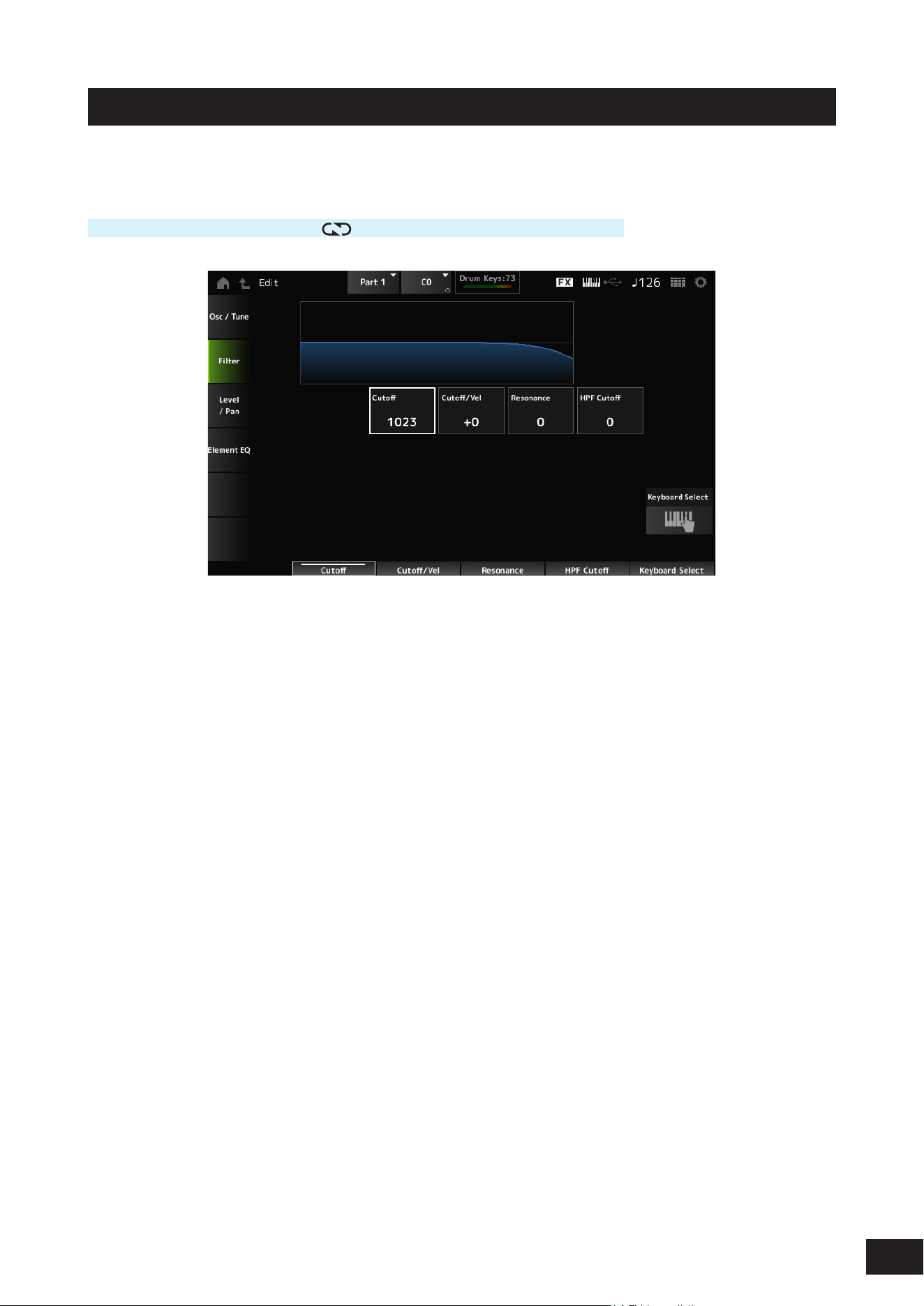
282
MODX M Operation Manual
Filter
Sets the lter for the Drum Part. You can change the tone quality by using a low pass lter and high pass lter on each
drum key.
Operation
[PERFORMANCE (HOME)]
→
[EDIT/ ]
→
Part selection
→
Key selection
→
Filter
Cutoff (LPF Cutoff Frequency)
Sets the cutoff frequency for the low pass lter.
Settings: 0–1023
Cutoff/Vel (LPF Cutoff Velocity Sensitivity)
Sets the velocity sensitivity to the cutoff frequency of the low pass lter.
For positive values of this parameter, the stronger (higher velocity) you play the key, the higher the cutoff frequency
becomes.
For negative values of this parameter, the stronger you play the key, the lower the cutoff frequency becomes.
Settings: −64–+0–+63
Resonance (LPF Resonance)
Sets the level of the resonance effect on the low pass lter.
Settings: 0–127
HPF Cutoff (HPF Cutoff Frequency)
Sets the cutoff frequency of the high pass lter.
Settings: 0–1023
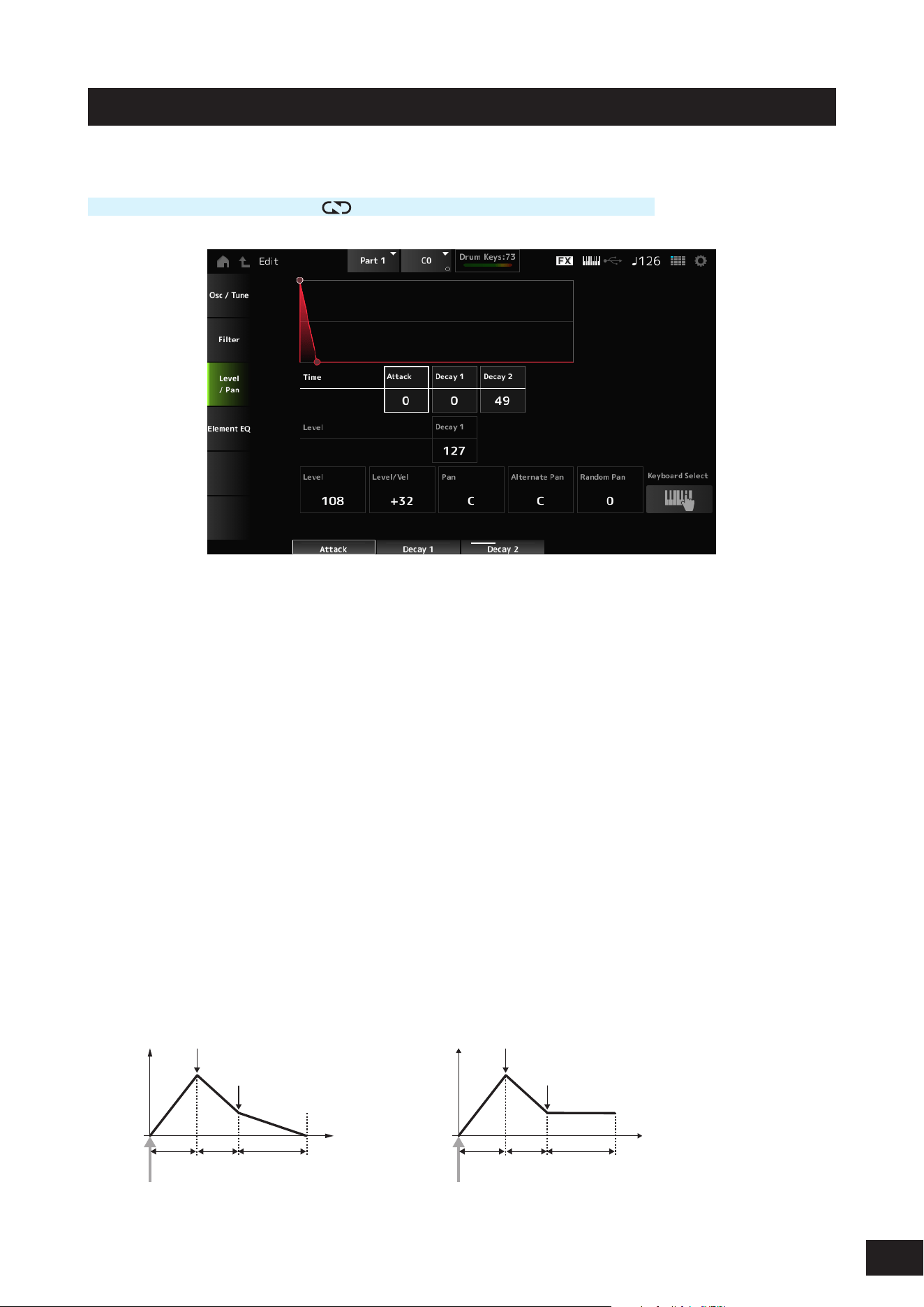
283
MODX M Operation Manual
Level/Pan
Sets the Level and Pan (position in the stereo eld) for each Drum Key.
Operation
[PERFORMANCE (HOME)]
→
[EDIT/ ]
→
Part selection
→
Key selection
→
Level/Pan
Attack Time (AEG Attack Time)
Sets the length of time it takes for the volume to change from the moment you press a key on the keyboard until the time
the volume reaches the value set at the Level (Drum Key Level).
Settings: 0–127
Decay 1 Time (AEG Decay 1 Time)
Sets the length of time it takes for the volume to change from the Level (Drum Key Level) to the Decay 1 Level (AEG
Decay 1 Level).
Settings: 0–127
Decay 2 Time (AEG Decay 2 Time)
Sets the length of time it takes for the volume to decay after reaching the volume set in Decay 1 Level (AEG Decay 1
Level).
Settings: 0–126, Hold
Decay 1 Level (AEG Decay 1 Level)
Sets the next volume value to change from the Level (Drum Key Level).
Settings: 0–127
Level (Drum Key Level)
Sets the output level for the Drum Key. This parameter lets you adjust the level balance among the drum keys.
Settings: 0–127
When Decay2 Time = 0–126 When Decay2 Time = hold
Time
Level Drum Key Level
Attack
Time
Decay 1
Time
Decay 2
Time
Decay 1 Level
Key on
Time
Level Drum Key Level
Attack
Time
Decay 1
Time
Decay 2
Time
Decay 1 Level
Key on

284
MODX M Operation Manual
Level/Vel (Level Velocity Sensitivity)
Sets how Level (Volume) responds to Velocity or the strength of the keystroke.
Settings: −64– +0–+63
Positive value: The faster the Velocity, the louder the volume becomes
0: No change regardless of the velocity setting.
Negative value: The slower the Velocity, the louder the volume becomes
Pan
Sets the Pan (location in the sound eld) of the drum key. You can adjust the position in the stereo eld for the Drum Part
(Drum Kit).
Settings: L63–C (center)–R63
Alternate Pan (Alternate Pan Depth)
Sets how the sound is panned alternately left and right for each key played.
The value set in Pan is the center position for the right and left movement of the Pan.
Settings: L63–C (Center)–R63
Random Pan (Random Pan Depth)
Sets how the sound is panned randomly left and right for each key played.
The value set in Pan is the center position in the stereo eld.
Settings: 0–127

285
MODX M Operation Manual
Element EQ
The same as Element EQ on the Part Edit (AWM2) Element Edit screen.
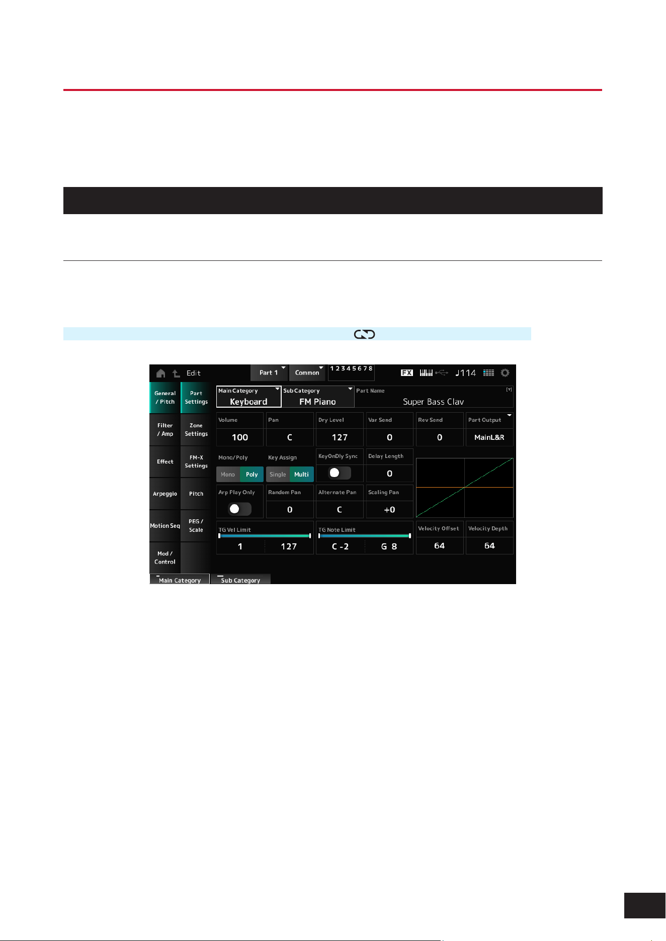
286
MODX M Operation Manual
Part Edit (FM-X) Part Common Edit Screens
The Normal Part (FM-X) consists of eight Operators.
Part Edit (FM-X) includes Part Common Edit (for setting parameters for the entire Part) and Operator Edit (for setting
parameters for individual operators).
General/Pitch
Part Settings
On the Part Settings screen, you can set general parameters (such as the Part names and tone generation system) for
the Part.
Operation
[PERFORMANCE (HOME)]
→
Part Common selection
→
[EDIT/ ]
→
General/Pitch
→
Part Settings
The screen here is the same as the one opened from General/Pitch
→
Part Settings on the Part Edit (AWM2) Part
Common Edit screen; however, the parameter shown below has been added.
Random Pan (Random Pan Depth)
Sets how the sound is panned randomly left and right for each key played.
The value set in Pan is the center position in the stereo eld.
Settings: 0–127
Alternate Pan (Alternate Pan Depth)
Sets how the sound is panned alternately left and right for each key played.
The value set in Pan is the center position for the right and left movement of the Pan.
Settings: L63–C (Center)–R63
Scaling Pan (Scaling Pan Depth)
Sets how the position of the key you press affects the position of the Pan setting. Note Number C3 is the reference point
for panning, and the position at this time is the value set in Pan.
By setting this parameter to a positive value, Pan is set to the left for lower keys, and to the right for higher keys.
When this parameter is set to a value of 0, there will be no changes to the Pan setting. When the parameter is set to a
negative value, the pan is set to the left for lower keys, and to the right for higher keys.
Settings: −64–+0–+63

287
MODX M Operation Manual
KeyOnDly Sync (Key On Delay Tempo Sync)
Sets the timing of the Key On Delay to synchronize with the tempo.
Settings: Off, On
Delay Length (Key On Delay Time Length)
Sets the delay time from when the moment the key is pressed to when sound is produced.
This parameter is not available when KeyOnDly Sync is set to On.
Settings: 0–127
Delay Length (Key On Delay Note Length)
This parameter is available when KeyOnDly Sync (Key On Delay Tempo Sync) is set to On. You can set the timing for Key
On Delay by using musical note values.
Settings: 1/16 (sixteenth notes), 1/8 Tri. (eighth-note triplets), 1/16 Dot. (dotted sixteenth notes), 1/8 (eighth notes), 1/4 Tri. (quarter-note
triplets), 1/8 Dot. (dotted eighth notes), 1/4 (quarter notes), 1/2 Tri. (half-note triplets), 1/4 Dot. (dotted quarter notes), 1/2 (half
notes), Whole Tri. (whole-note triplets), 1/2 Dot. (dotted half notes), 1/4 × 4 (quarter-note quadruplets; four quarter notes to the
beat), 1/4 × 5 (quarter-note quintuplets; five quarter notes to the beat), 1/4 × 6 (quarter-note sextuplets; six quarter notes to the
beat), 1/4 × 7 (quarter-note septuplets; seven quarter notes to the beat), 1/4 × 8 (quarter-note octuplets; eight quarter notes to
the beat)
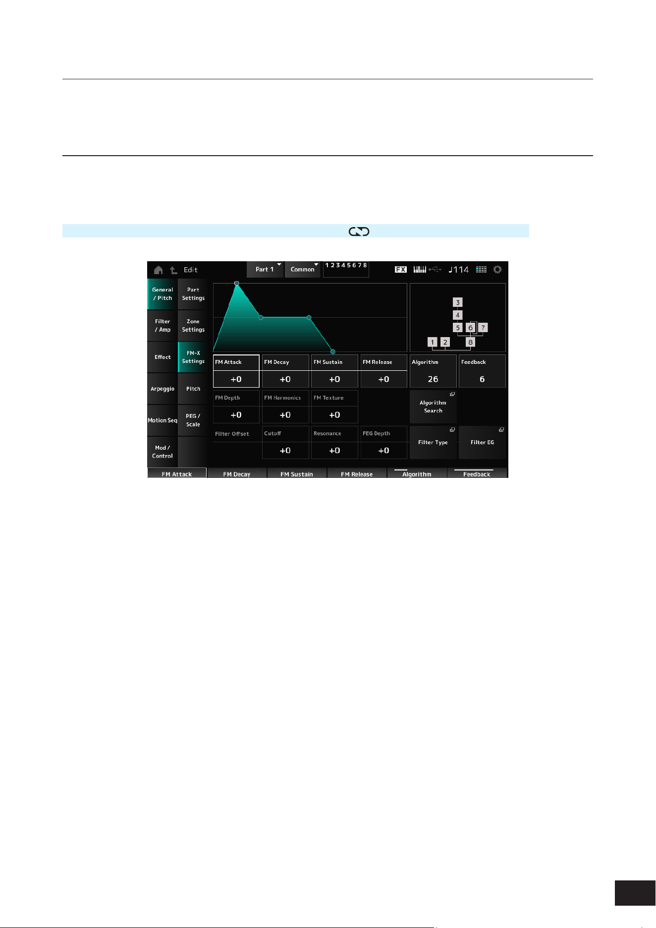
288
MODX M Operation Manual
Zone Settings
The same as General/Pitch
→
Zone Settings on the Part Edit (AWM2) Part Common Edit screen.
FM-X Settings
On the FM-X Settings screen, you can set the FM Color parameters provided as a convenient editing tool for the FM-X
sounds as well as the Algorithm (or how the Operators are arranged).
Operation
[PERFORMANCE (HOME)]
→
Part Common selection
→
[EDIT/ ]
→
General/Pitch
→
FM-X Settings
FM Attack
Controls the Attack Time of the EG that changes the depth of the frequency modulation over time.
Settings: −99–+0–+99
FM Decay
Controls the Decay Time of the EG that changes the depth of the frequency modulation over time.
Settings: −99–+0–+99
FM Sustain
Controls the Sustain Level of the EG that changes the depth of the frequency modulation over time.
Settings: −99–+0–+99
FM Release
Controls the Release Time of the EG that changes the depth of the frequency modulation over time.
Settings: −99–+0–+99
Algorithm (Algorithm Number)
Changes the Algorithm.
Settings: Refer to the Data List
Feedback (Feedback Level)
Feedback causes the Operator to modulate itself by sending some of the output signals back.
Here with this parameter, you can set the degree of such modulation.
Settings: 0–7
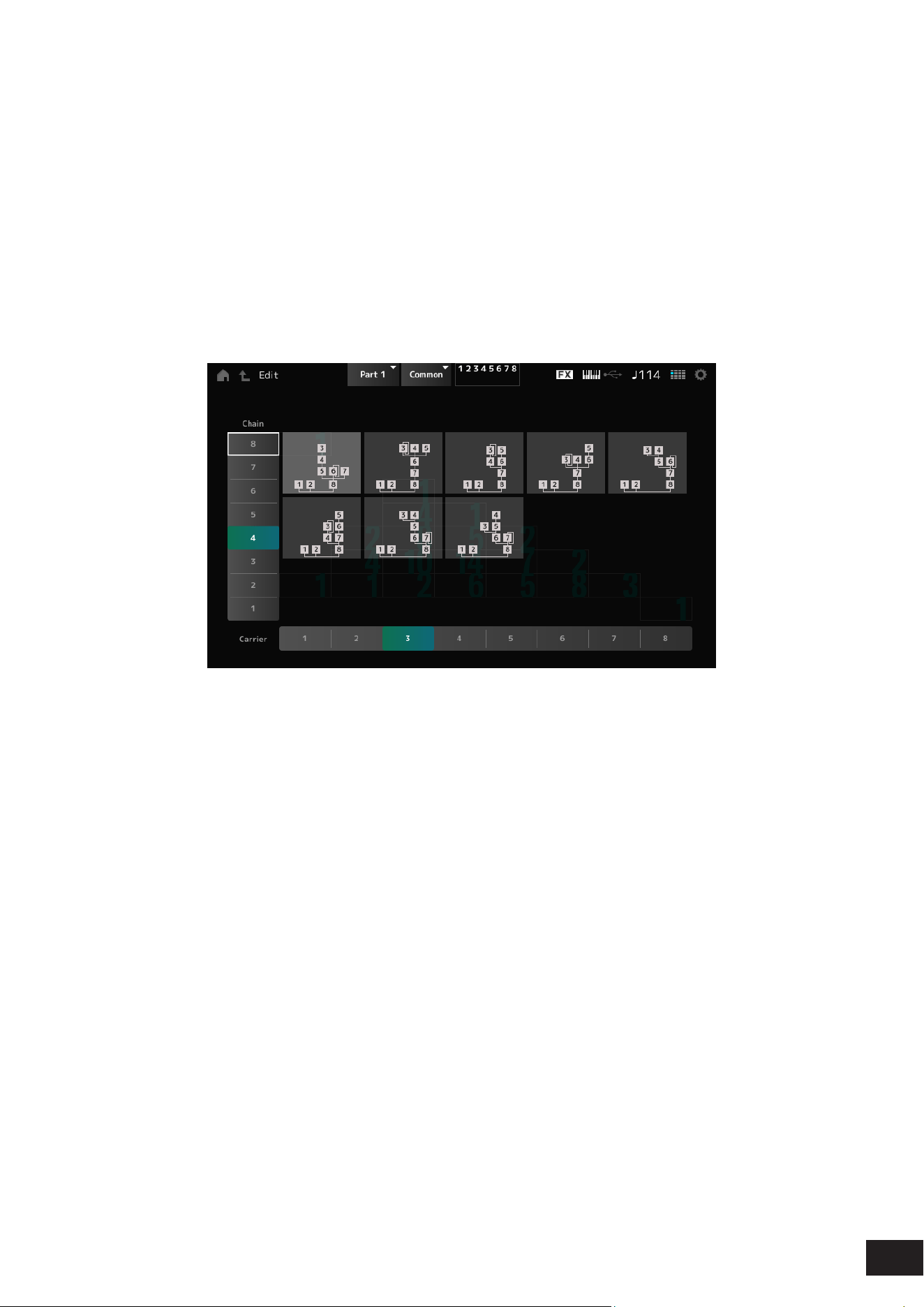
289
MODX M Operation Manual
FM Depth
Changes the depth of the frequency modulation.
Settings: −99–+0–+99
FM Harmonics
Changes the frequency of the harmonic overtones of FM synthesis.
Settings: −99–+0–+99
FM Texture
Changes the texture of FM synthesis.
Settings: −99–+0–+99
Algorithm Search
Opens the Algorithm Search screen.
• Chain
Filters the available algorithms based on the maximum length of the operators connected in series.
• Carrier
Filters the available algorithms based on number of carriers.
Filter Offset Cutoff (Filter Cutoff Frequency)
Changes the sound by setting the cutoff frequency of the lter. When the Low Pass Filter is selected, larger values here
result in a brighter sound, and smaller values result in a darker sound.
This parameter is specied as an offset value to the lter cutoff frequency.
Settings: −64–+0–+63
Filter Offset Resonance (Filter Offset Resonance/Width)
Adds special characteristics to the sound by adjusting the signal level near the cutoff frequency.
This is specied as an offset value to the lter resonance.
Settings: −64–+0–+63
Filter Offset FEG Depth
Sets the depth range for the cutoff frequency change controlled by the FEG.
Settings: −64–+0–+63
Filter Type
The Filter Type screen will open.
Filter EG
The Filter EG screen will open.
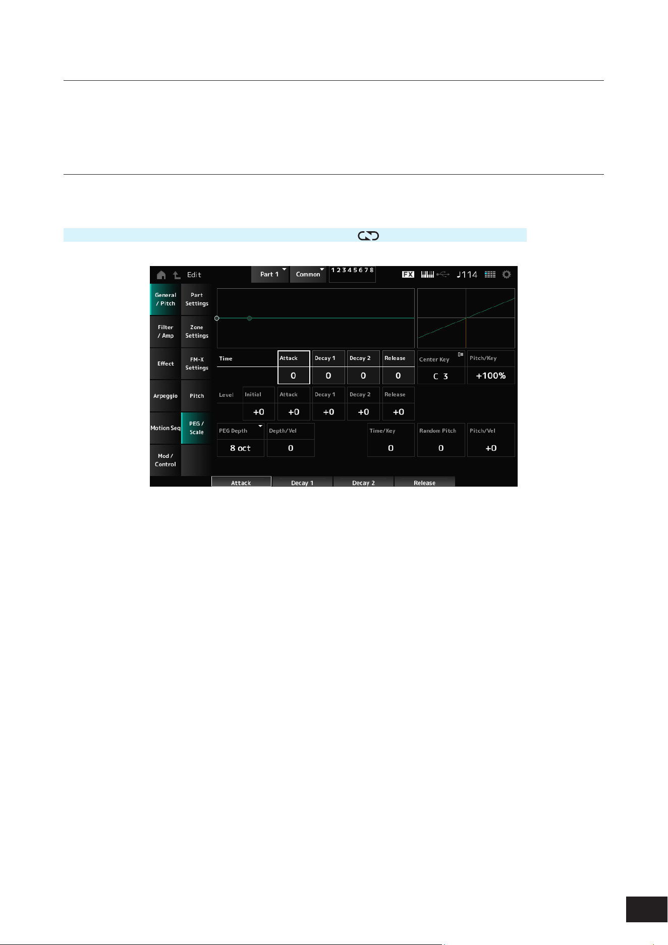
290
MODX M Operation Manual
Pitch
The screen here is the same as the one opened from General/Pitch
→
Pitch on the Part Edit (AWM2) Part Common Edit
screen, except that Legato Slope (Portamento Legato Slope) is disabled.
PEG/Scale
On the PEG/Scale screen, you can set the pitch envelope generator and scale for the Part.
Operation
[PERFORMANCE (HOME)]
→
Part Common selection
→
[EDIT/ ]
→
General/Pitch
→
PEG/Scale
Attack Time (PEG Attack Time)
Sets the length of time it takes for the pitch to change from the moment you press a key on the keyboard until the time the
pitch reaches the value set at Attack Level (PEG Attack Level).
Settings: 0–99
Decay1 Time (PEG Decay 1 Time)
Sets the length of time it takes for the pitch to change from the Attack Level (PEG Attack Level) to the Decay1 Level (PEG
Decay 1 Level).
Settings: 0–99
Decay2 Time (PEG Decay 2 Time)
Sets the length of time it takes for the pitch to change from the Decay1 Level (PEG Decay 1 Level) to the Decay2 Level
(PEG Decay 2 Level).
Settings: 0–99
Release Time (PEG Release Time)
Sets the length of time it takes for the pitch to change from the moment you have released the key until it reaches the
Release Level (PEG Release Level).
Settings: 0–99
Center Key (Pitch Key Follow Sensitivity Center Key)
Sets the reference key for Pitch/Key (Pitch Key Follow Sensitivity).
Settings: C−2–G8

291
MODX M Operation Manual
Pitch/Key (Pitch Key Follow Sensitivity)
Sets the difference in pitch between two adjacent keys. The note set in Center Key (Pitch Key Follow Sensitivity Center
Key) is used as the reference.
Settings: −200%–+0%–+200%
+100% (default): Pitch difference between the two keys next to each other is set to a semitone
0%: No pitch difference between the two keys, and all keys are played at the pitch set in Center Key (Pitch Key Follow
Sensitivity Center Key)
Negative value: Sets an opposite pitch response such that lower notes result in higher pitch, and higher notes result in lower
pitch.
Initial Level (PEG Initial Level)
Sets the pitch for the moment you press the key.
Settings: −50–+0–+50
Attack Level (PEG Attack Level)
Sets the pitch to change from Initial Level (PEG Initial Level) after you have pressed a key.
Settings: −50–+0–+50
Decay1 Level (PEG Decay 1 Level)
Sets the next pitch value to change from the Attack Level (PEG Attack Level).
Settings: −50–+0–+50
Decay2 Level (PEG Decay 2 Level)
Sets the next pitch value to change from the Decay1 Level (PEG Decay 1 Level).
Settings: −50–+0–+50
Release Level (PEG Release Level)
Sets the nal pitch to reach after you have released the key.
Settings: −50–+0–+50
PEG Depth
Sets the amount of pitch change controlled by the PEG.
Settings: 8 oct, 2 oct, 1 oct, 0.5 oct
NOTE
When this parameter is set to 8 oct, you can specify the smallest value to the Pitch EG level to create a pitch change of −4 octaves by
sending the pitch value 0 to the internal tone generator, and by specifying the largest value to create a pitch change of +4 octaves.
Depth/Vel (PEG Depth Velocity Sensitivity)
Sets how the time of the pitch change in PEG responds to Velocity or the strength of the keystroke.
Settings: 0–7
Time/Key (PEG Time Key Follow Sensitivity)
Sets how the speed of the pitch change in PEG responds to key position.
Center Key (Pitch Key Follow Sensitivity Center Key): The speed change in PEG is used for the specied key xed to C3.
Settings: 0–7
Positive value: The lower the key played, the slower the change in the PEG; the higher the key played, the faster the change
in the PEG.
0: No PEG changes regardless of the key position
Random Pitch (Random Pitch Depth)
Changes the pitch of the Element randomly each time the key is pressed.
Settings: 0–127
Pitch/Vel (Pitch Velocity Sensitivity)
Sets how the pitch responds to Velocity or the strength of the keystroke.
Settings: −64–+0–+63
Positive value: The faster the Velocity, the higher the pitch becomes
0: kept unchanged
Negative value: The faster the Velocity, the lower the pitch becomes

292
MODX M Operation Manual
Filter/Amp
Filter Type
The same as Filter
→
Type on the Part Edit (AWM2) Element Edit screen.
Filter EG
The same as Filter
→
Filter EG on the Part Edit (AWM2) Element Edit screen.
Filter Scale
The same as Filter
→
Scale on the Part Edit (AWM2) Element Edit screen.
Amp EG
The same as Filter/Amp
→
Amp EG on the Part Edit (AWM2) Part Common Edit screen.

293
MODX M Operation Manual
Effect
Routing
The screen here is almost the same as the one opened from Effect
→
Routing on the Part Edit (AWM2) Part Common Edit
screen, with the exceptions listed below.
• No output setting for each Element
• Cannot select Parallel for Ins Connect
Ins A, Ins B
The same as Effect
→
InsA and InsB on the Part Edit (AWM2) Part Common Edit screen.
3-band EQ
The same as Effect
→
3-band EQ on the Part Edit (AWM2) Part Common Edit screen.
2-band EQ
The same as Effect
→
2-band EQ on the Part Edit (AWM2) Part Common Edit screen.
Ins Assign
The same as Effect
→
Ins Assign on the Part Edit (AWM2) Part Common Edit screen.

294
MODX M Operation Manual
Arpeggio
Common
The same as Arpeggio
→
Common on the Part Edit (AWM2) Part Common Edit screen.
Individual
The same as Arpeggio
→
Individual on the Part Edit (AWM2) Part Common Edit screen.
Advanced
The same as Arpeggio
→
Advanced on the Part Edit (AWM2) Part Common Edit screen.

295
MODX M Operation Manual
Motion Seq
Common
The same as Motion Seq
→
Common on the Part Edit (AWM2) Part Common Edit screen.
Lane
The same as Motion Seq
→
Lane on the Part Edit (AWM2) Part Common Edit screen.
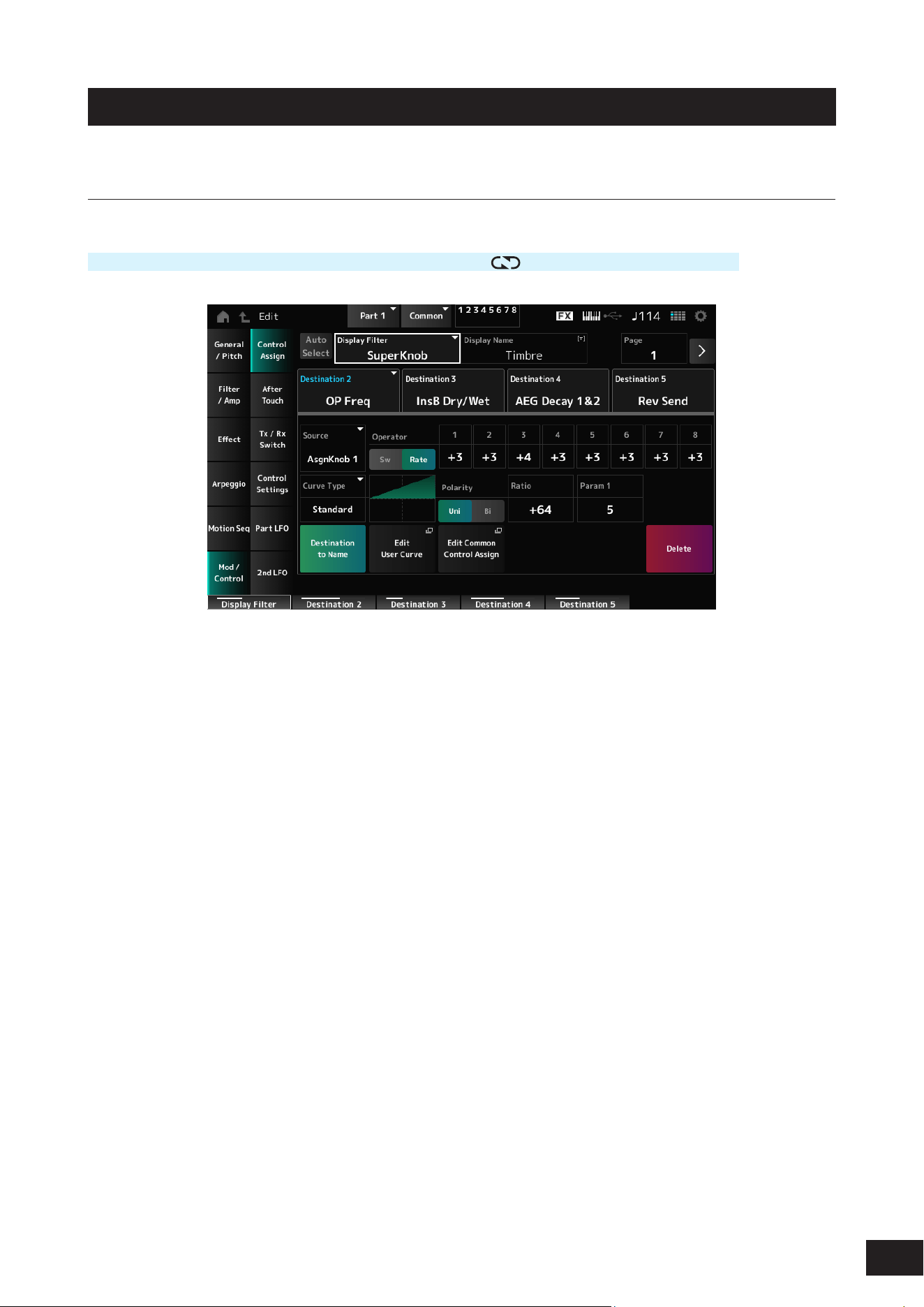
296
MODX M Operation Manual
Mod/Control
Control Assign
Operation
[PERFORMANCE (HOME)]
→
Part Common selection
→
[EDIT/ ]
→
Mod/Control
→
Control Assign
Other than the Destination setting, the same as Mod/Control
→
Control Assign on the Part Edit (AWM2) Part Common
Edit screen.
For a list of settings, refer to the Data List.
Use the parameters shown below, instead of ElementSw and others.
Operator Sw 1–8 (Operator Switch)
You can set the controller setting for each Operator on or off. This parameter is shown only when the selected Destination
is related to Operators.
Settings: Off, On
Sw/Rate
Switches the view between Operator Sw and Operator Rate.
This parameter is shown only when the Destination is set to OP Freq or OP AEG Offset.
Settings: Off, On
Operator Rate 1–8
Sets the sensitivity of the controller selected for the Destination.
This parameter is shown only when the Destination is set to OP Freq or OP AEG Offset.
Settings: −7–+0–+7
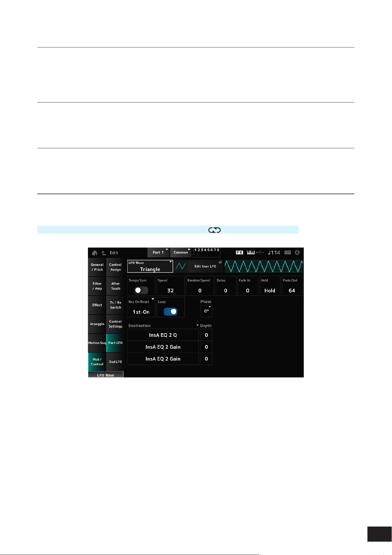
297
MODX M Operation Manual
After Touch
Other than the Destination setting, the same as Mod/Control
→
After Touch on the Part Edit (AWM2) Part Common Edit
screen.
Tx /Rx Switch
The same as Mod/Control
→
Tx/Rx Switch on the Part Edit (AWM2) Part Common Edit screen.
Control Settings
The same as Mod/Control
→
Control Settings on the Part Edit (AWM2) Part Common Edit screen.
Part LFO
On the Part LFO screen, you can set the Part LFO.
Operation
[PERFORMANCE (HOME)]
→
Part Common selection
→
[EDIT/ ]
→
Mod/Control
→
Part LFO
LFO Wave
Selects the LFO Wave and sets the type of cyclical changes to the LFOs.
Settings: Triangle, Triangle+, Saw Up, Saw Down, Squ1/4, Squ1/3, Square, Squ2/3, Squ3/4, Trapezoid, S/H1, S/H2, User
Edit User LFO
The User LFO Edit screen will open.
You can create an LFO waveform of up to 16 steps.
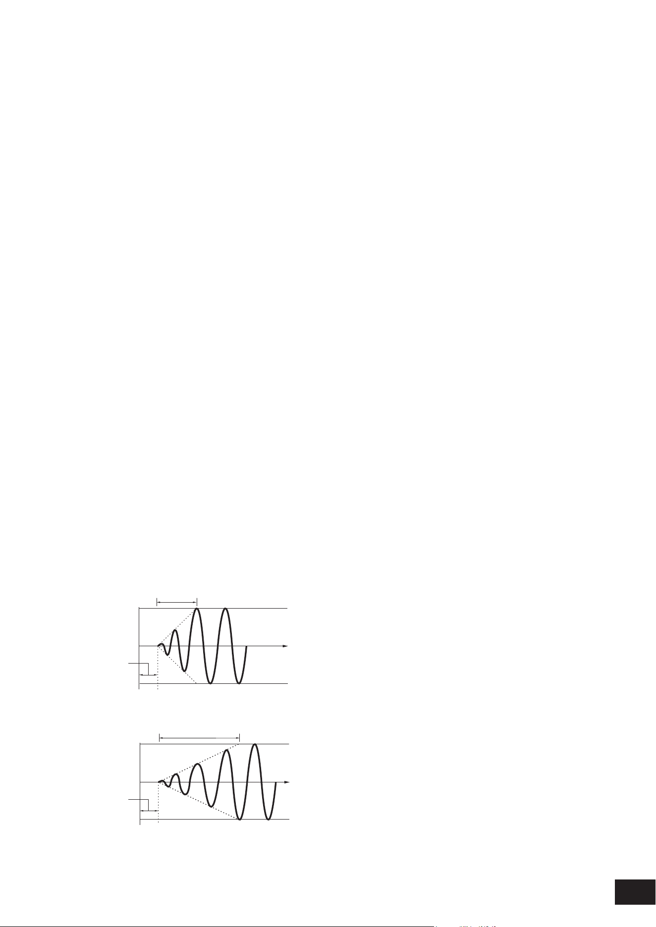
298
MODX M Operation Manual
Tempo Sync (LFO Tempo Sync)
Sets the speed of the LFO Wave changes to synchronize to Arpeggio or Song playback.
Settings: Off (not synchronized), On (synchronized)
• When set to Off
Speed (LFO Speed)
Sets the speed of LFO Wave changes.
This parameter is not available when Tempo Sync (LFO Tempo Sync) is set to On.
Settings: 0–63
Random Speed (Part LFO Random Speed Depth)
Changes the LFO Speed randomly.
This parameter is not available when Tempo Sync (LFO Tempo Sync) is set to On.
Settings: 0–127
• When set to On
Tempo Speed (LFO Tempo Speed)
Sets the speed of LFO Wave changes by using musical note values.
Settings: 1/16 (sixteenth notes), 1/8 Tri. (eighth-note triplets), 1/16 Dot. (dotted sixteenth notes), 1/8 (eighth notes), 1/4 Tri. (quarter-note
triplets), 1/8 Dot. (dotted eighth notes), 1/4 (quarter notes), 1/2 Tri. (half-note triplets), 1/4 Dot. (dotted quarter notes), 1/2 (half
notes), Whole Tri. (whole-note triplets), 1/2 Dot. (dotted half notes), 1/4 × 4 (quarter-note quadruplets; four quarter notes to
the beat), 1/4 × 5 (quarter-note quintuplets; ve quarter notes to the beat), 1/4 × 6 (quarter-note sextuplets; six quarter notes
to the beat), 1/4 × 7 (quarter-note septuplets; seven quarter notes to the beat), 1/4 × 8 (quarter-note octuplets; eight quarter
notes to the beat), 1/4 × 16 (sixteen quarter-notes to the beat), 1/4 × 32 (thirty-two quarter-notes to the beat), 1/4 × 64 (sixty-
four quarter-notes to the beat)
Delay (LFO Delay Time)
Sets the delay time between the moment you press a key on the keyboard and the moment the LFO comes into effect.
The larger the value, the longer the delay time for the LFO to come into effect.
Settings: 0–127
Fade In (LFO Fade In Time)
Sets the time length for the LFO effect to fade in after you have released the key and the delay time set in Delay (LFO
Delay Time) has elapsed. The larger the value, the longer it takes for the LFO effect to reach the maximum.
Settings: 0–127
0: The LFO changes to the maximum value without any fade-ins.
When the value is small
Fade In
Maximum
Delay
Key On
Time
When the value is large
Fade In
Maximum
Delay
Key On
Time
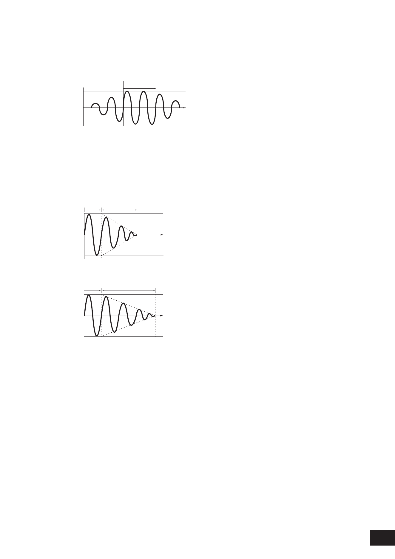
299
MODX M Operation Manual
Hold (LFO Hold Time)
Sets the time for maintaining the LFO effect after the maximum level has been reached.
Settings: 0–126, Hold
Hold: Does not fade out
Hold
Maximum
Key On
Time
Fade Out (LFO Fade Out time)
Sets the amount of time for the LFO effect to fade out after the hold time set in Hold (LFO Hold Time) has elapsed. The
larger the value, the longer it takes for the LFO effect to fade out.
Settings: 0–127
When the value is small
Fade-Out
Maximum
Hold
Key On
Time
When the value is large
Fade-Out
Maximum
Hold
Key On
Time
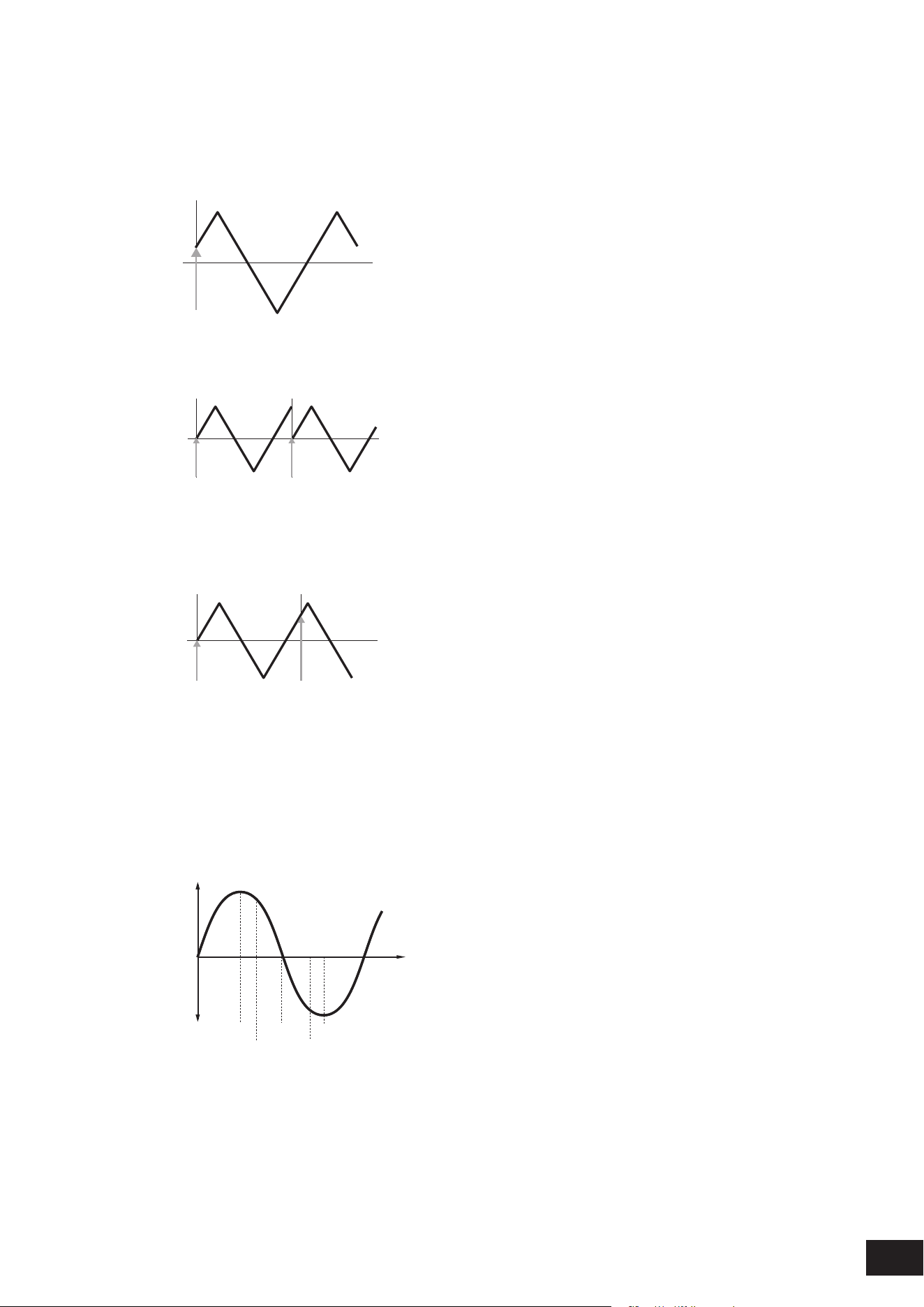
300
MODX M Operation Manual
Key On Reset (LFO Key On Reset)
Resets the oscillation of the LFO when a key is pressed.
Settings: Off, Each-on, 1st-on
When set to Off
Does not reset the oscillation of the LFO. Pressing a key starts the LFO wave at whatever phase the LFO happens to be at that
moment.
Key On
Time
When set to Each-on
Resets the oscillation of LFO every time a key is pressed and starts the waveform at the phase specied by the Phase
parameter.
Key On
(first note)
Key On
(second note)
Time
When set to 1st-on
Resets the oscillation of LFO every time a key is pressed and starts the waveform at the phase specied by the Phase
parameter.
When the second note is played while the rst note is held, playback will not be reset.
Key On
(first note)
Key On
(second note)
Time
Loop (LFO Loop Switch)
Sets the LFO Wave to loop (repeat) playback or one-shot playback.
Settings: Off, On
Phase (LFO Phase)
You can set the initial phase for the time the LFO Wave is reset.
Settings: 0°, 90°, 120°, 180°, 240°, 270°
Phase
Time
Level
0°
90°
120°
240°
180° 270°
Destination (LFO Destination)
Sets the function to be controlled by the LFO Wave.
Settings: Insertion Effect A Parameter1–24, Insertion Effect B Parameter1–24 (depending on the Insertion Effect)
Depth (LFO Depth)
Sets the depth of LFO Wave control for each Destination.
Settings: 0–127
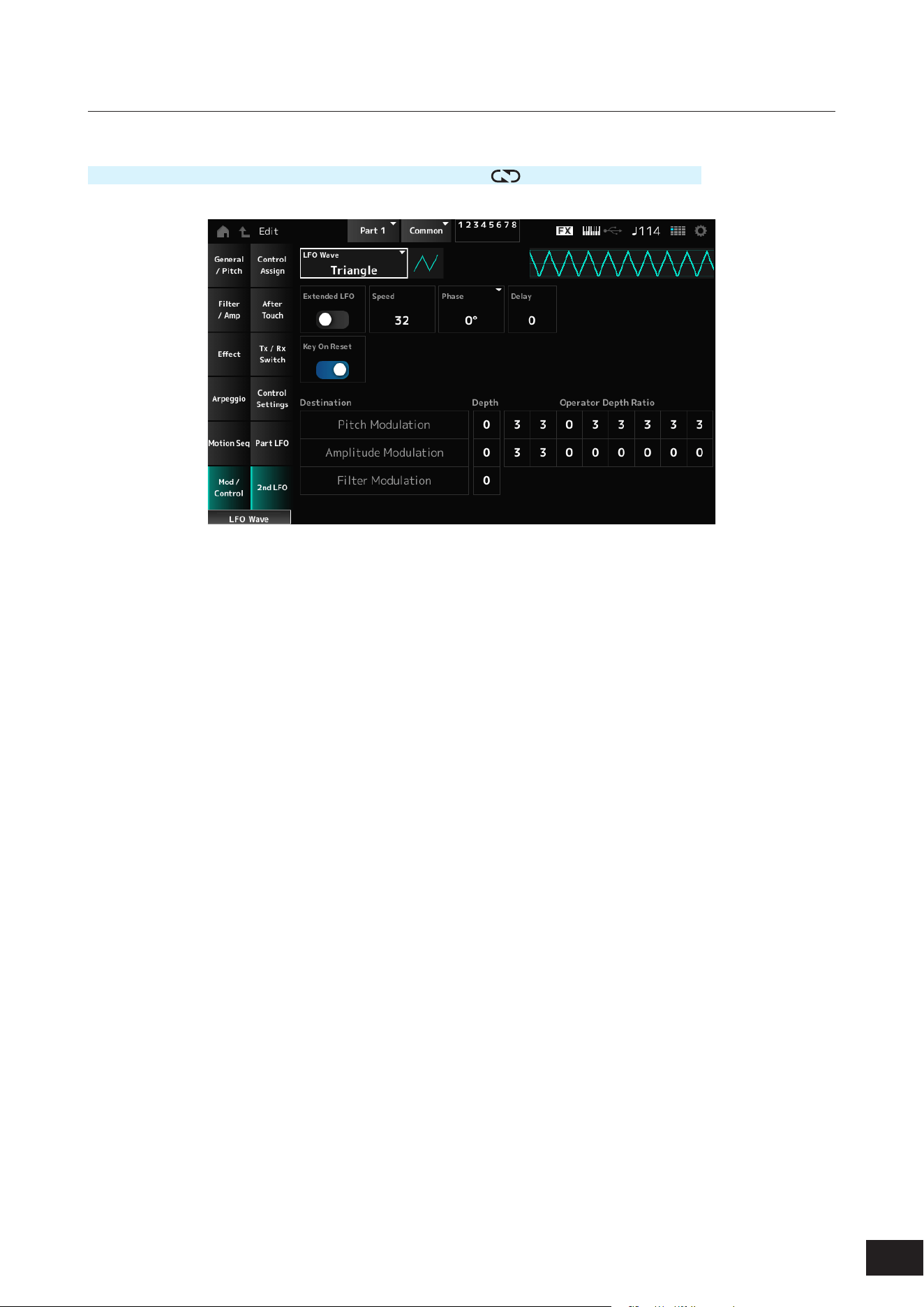
301
MODX M Operation Manual
2nd LFO
Operation
[PERFORMANCE (HOME)]
→
Part Common selection
→
[EDIT/ ]
→
Mod/Control
→
2nd LFO
LFO Wave (2nd LFO Wave)
Selects the 2nd LFO.
Settings: Triangle, Saw Down, Saw Up, Square, Sine, S/H
NOTE
The Amplitude Modulation phase is shifted with Sine.
Extended LFO (2nd LFO Extended LFO)
Switches between the old set of Speed (2nd LFO Speed) settings (Off: 0–99) and a new set of settings with higher
resolution (On: 0–415) for Speed (LFO Speed).
To maintain compatibility of data created with the old settings, set this parameter to Off.
Settings: Off, On
Speed (2nd LFO Speed)
Sets the speed of LFO Wave (2nd LFO Wave) changes.
Settings: 0–99 (When Extended LFO is set to Off), 0–415 (When Extended LFO is set to On)
Phase (2nd LFO Phase)
You can set the initial phase for the time the LFO Wave (2nd LFO Wave) is reset.
Settings: 0°, 90°, 180°, 270°
Delay (2nd LFO Delay Time)
Sets the time length for the 2nd LFO effect to fade in after you have released the key and the delay time set in Delay has
elapsed.
Settings: 0–99
Key On Reset (2nd LFO Key On Reset)
Resets the oscillation of the 2nd LFO when a key is pressed.
Settings: Off, On

302
MODX M Operation Manual
Pitch Modulation Depth (2nd LFO Pitch Modulation Depth)
This parameter creates a vibrato effect (cyclical changes to the pitch) by using the LFO Wave (2nd LFO Wave) and lets
you specify the depth of lter modulation by the LFO.
Settings: 0–99
Pitch Modulation Operator Depth Ratio 1~8 (2nd LFO Pitch Modulation Depth Offset)
Sets the depth of the modulation by LFO signals set in Pitch Modulation Depth (2nd LFO Pitch Modulation Depth).
Settings: 0–7
Amplitude Modulation Depth (2nd LFO Amplitude Modulation Depth)
This parameter creates cyclical changes in the volume by using the LFO Wave (2nd LFO Wave) and lets you specify the
depth of lter modulation by the LFO.
Settings: 0–99
Amplitude Modulation Operator Depth Ratio 1~8 (2nd LFO Amplitude Modulation Depth Offset)
Sets the depth of the modulation by LFO signals set in Amplitude Modulation Depth (2nd LFO Amplitude Modulation
Depth).
Settings: 0–7
Filter Modulation Depth (2nd LFO Filter Modulation Depth)
This parameter creates cyclical changes to the lter cutoff frequency by using the LFO Wave (2nd LFO Wave) and lets you
specify the depth of lter modulation by the LFO.
Settings: 0–99
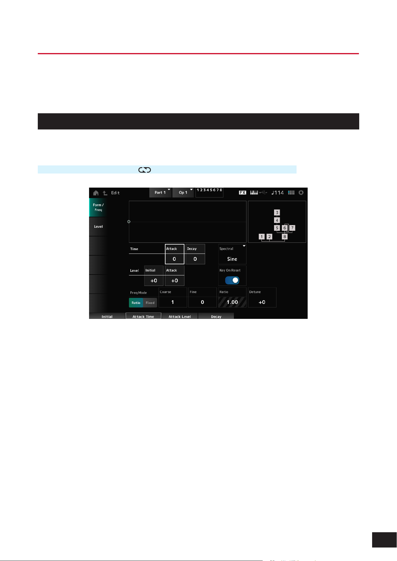
303
MODX M Operation Manual
Part Edit (FM-X) Operator Edit Screens
The Normal Part (FM-X) consists of eight Operators.
Part Edit (FM-X) includes Part Common Edit (for setting parameters for the entire Part) and Operator Edit (for setting
parameters for individual operators).
Form/Freq
On the Form/Freq screen, you can set the waveform and frequency of the Operator.
Operation
[PERFORMANCE (HOME)]
→
[EDIT/ ]
→
Part selection
→
Operator selection
→
Form/Freq
Attack Time (PEG Attack Time)
Sets the length of time it takes for the pitch to change from the moment you press a key on the keyboard until the time the
pitch reaches the value set at Attack Level (PEG Attack Level).
Settings: 0–99
Decay Time (PEG Decay Time)
Sets the length of time it takes for the pitch to change from the value set at the Attack Level (PEG Attack Level) to the
moment the PEG changes to the value 0.
Settings: 0–99
Initial Level (PEG Initial Level)
Sets the pitch for the moment you press the key.
Settings: −50–+0–+50

304
MODX M Operation Manual
Attack Level (PEG Attack Level)
Sets the pitch to change from Initial Level (PEG Initial Level) after you have pressed a key.
Settings: −50–+0–+50
Time
Level
+50
−50
Attack
Time
Decay
Time
Attack Level
Initial Level
Spectral (Spectral Form)
Sets the waveform for the selected Operator.
Settings: Sine, All 1, All 2, Odd 1, Odd 2, Res 1, Res 2
Sine: Sine wave with no harmonic overtones
All 1: Wave with harmonic overtones in a wide Spectral range
All 2: Wave with harmonic overtones in a narrow Spectral range
Odd 1: Wave containing odd harmonics in a wide Spectral range
Odd 2: Wave containing odd harmonics in a narrow Spectral range
Res 1: Wave having a peak on a particular harmonic in a wide Spectral range
Res 2: Wave having a peak on a particular harmonic in a narrow Spectral range
Skirt (Spectral Skirt)
Sets the width of the transition band (skirt). The smaller the value, the narrower the skirt becomes to boost a particular
harmonic.
This parameter is not available when the Spectral (Spectral Form) is set to Sine.
Settings: 0–7
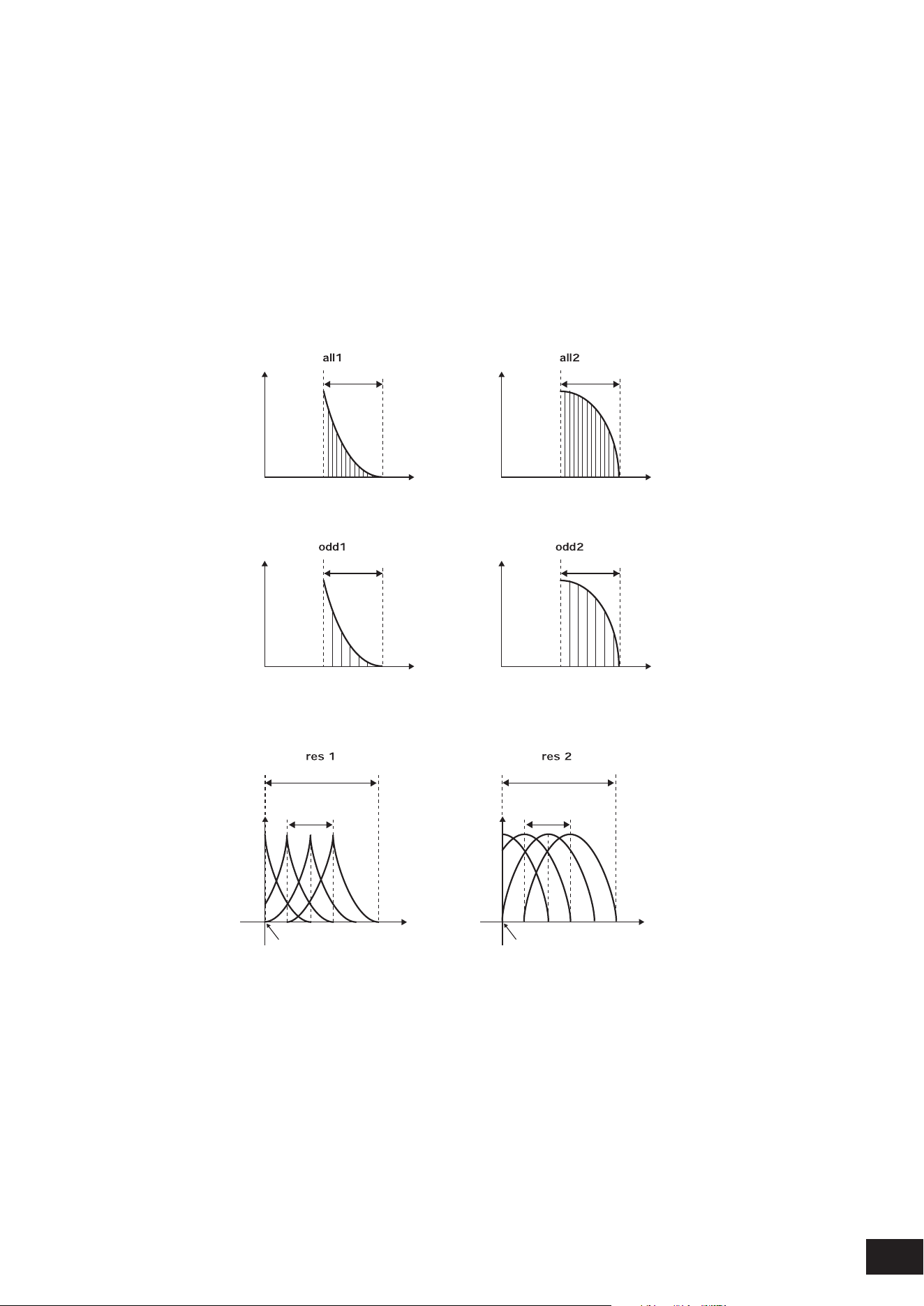
305
MODX M Operation Manual
Resonance (Spectral Resonance)
Sets the sensitivity of the resonance effect in Spectral.
The center frequency will be shifted to higher-order harmonics, so you can create the resonance effect or add special
characteristics to the sound.
This parameter is available only when Spectral (Spectral Form) is set to Res 1 or Res 2.
Settings: 0–99
Sine is a simple waveform containing only the fundamental wave with no harmonics, while other waveforms contain
harmonic overtones. Therefore, when you have set Form to a wave other than Sine, the parameters related to the
harmonics and its “peak” values (formants) will be available.
Below are some specic parameters for controlling each wave explained in Spectral.
Level
Level
Level
Level
Skirt Skirt
Skirt Skirt
Center Frequency
(F.Coarse & Freq Fine)
Center Frequency
(F.Coarse & Freq Fine)
Center Frequency
(F.Coarse & Freq Fine)
Center Frequency
(F.Coarse & Freq Fine)
Frequency
(Hz)
Frequency
(Hz)
Frequency
(Hz)
Frequency
(Hz)
You can increase the number of harmonic overtones by setting a larger Skirt value to expand the spectrum range.
Level Level
Skirt
Resonance of
Center Frequency
Resonance of
Center Frequency
Skirt
Center Frequency
(F.Coarse & Freq Fine)
Center Frequency
(F.Coarse & Freq Fine)
Frequency (Hz) Frequency (Hz)
Setting a larger Resonance value will shift the center frequency to higher-order harmonics.
Resonance is set to 0: Shifts to the rst harmonic.
Resonance is set to 99: Shifts to the 100th harmonic.

306
MODX M Operation Manual
Key On Reset (Oscillator Key On Reset)
Resets the oscillation of the Oscillator when a key is pressed.
Settings: Off, On
Off: If you play a key without resetting the oscillator, the signal waveform will start regardless of the phase at that moment
Pitch/Vel (Pitch Velocity Sensitivity)
Sets how the pitch responds to Velocity or the strength of the keystroke.
This parameter is available only when Freq Mode (Oscillator Frequency Mode) is set to Fixed.
Settings: −7–+0–+7
Positive value: The faster the Velocity, the higher the pitch becomes
0: kept unchanged
Negative value: The faster the Velocity, the lower the pitch becomes
Freq Mode (Oscillator Frequency Mode)
Sets the output pitch of the Operator.
Settings: Ratio, Fixed
Ratio: Sets the output pitch according to the key
Fixed: Sets the pitch to the Coarse or Fine setting, regardless of the pitch of the key being pressed
Coarse (Coarse Tune)
Adjusts the output pitch of each Operator.
Settings: When Freq Mode is set to Ratio: 0–31, When Freq Mode is set to Fixed: 0–21
Fine (Fine Tune)
Finely adjusts the output pitch of each Operator.
Settings: When Freq Mode is set to Ratio: 0–99, When Freq Mode is set to Fixed: 0–127
Detune
Sets the output pitch of each Operator slightly higher or lower.
When the same value is set to Coarse (Coarse Tune) or Fine (Fine Tune), the Operator with the Detune setting will have
slight pitch differences. As a result, you can create a warmer sound or chorusing effect.
Settings: −15–+0–+15
Pitch/Key (Pitch Key Follow Sensitivity)
Sets the difference in pitch between two adjacent keys. This parameter is available only when Freq Mode (Oscillator
Frequency Mode) is set to Fixed.
Settings: 0–99
0: No pitch difference between the two adjacent keys and all keys are played at the pitch set in Coarse or Fine
99: Pitch difference between two adjacent keys is set to a semitone
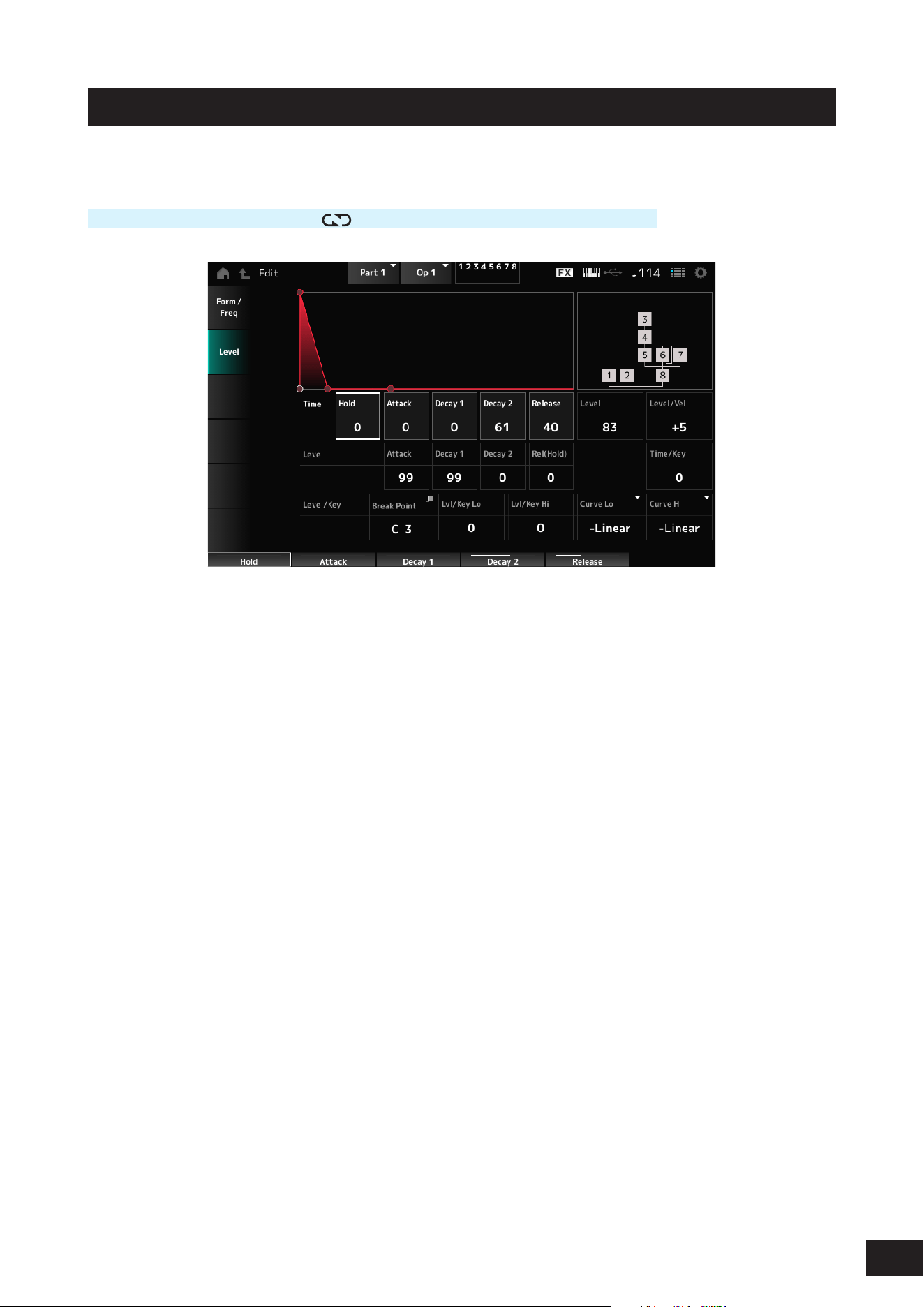
307
MODX M Operation Manual
Level
On the Level screen, you can set the general parameters for the Operator.
Operation
[PERFORMANCE (HOME)]
→
[EDIT/ ]
→
Part selection
→
Operator selection
→
Level
Hold Time (AEG Hold Time)
Sets the length of time it takes for the value to change from the moment you press a key on the keyboard until the time
the value reaches the Rel (Hold) Level (AEG Release (Hold) Level).
Settings: 0–99
Attack Time (AEG Attack Time)
Sets the length of time it takes for the value to change from the moment you press a key on the keyboard until the time
the value reaches the Attack Level (AEG Attack Level).
Settings: 0–99
Decay 1 Time (AEG Decay 1 Time)
Sets the length of time it takes for the value to change from the Attack Level (AEG Attack Level) to the Decay 1 Level (AEG
Decay 1 Level).
Settings: 0–99
Decay 2 Time (AEG Decay 2 Time)
Sets the length of time it takes for the value to change from the Decay 1 Level (AEG Decay 1 Level) to the Decay 2 Level
(AEG Decay 2 Level).
Settings: 0–99
Release Time (AEG Release Time)
Sets the length of time it takes for the value to change from the moment you have released the key until the time the value
reaches the Rel (Hold) Level (AEG Release (Hold) Level).
Settings: 0–99
Attack Level (AEG Attack Level)
Sets the value to be changed to after pressing a key.
Settings: 0–99
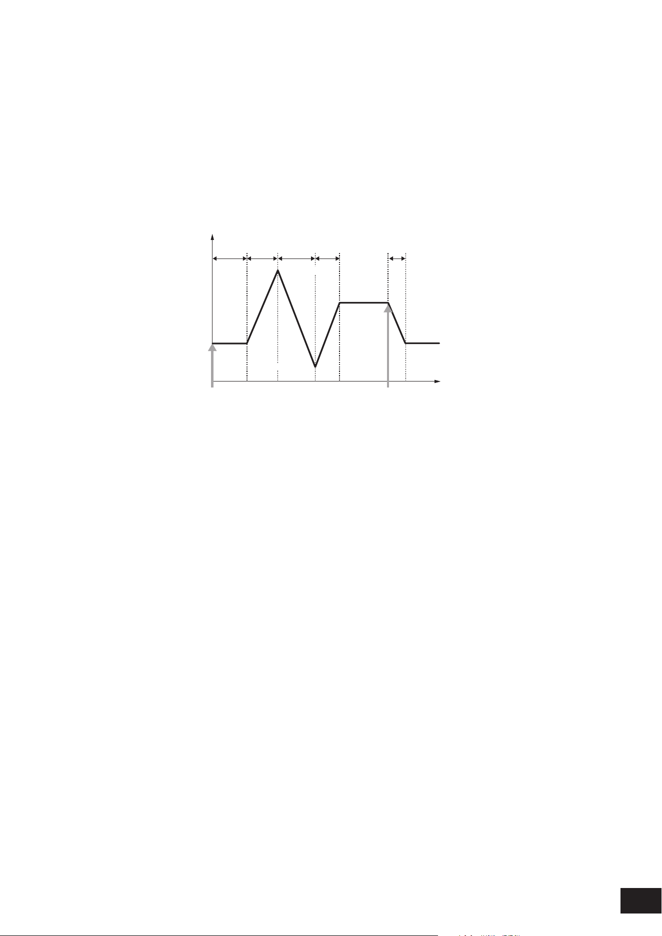
308
MODX M Operation Manual
Decay 1 Level (AEG Decay 1 Level)
Sets the next value to change from the Attack Level (AEG Attack Level).
Settings: 0–99
Decay 2 Level (AEG Decay 2 Level)
Sets the value that is maintained while the key is held down.
Settings: 0–99
Rel (Hold) Level (AEG Release (Hold) Level)
Sets the nal value to reach after you have released the key.
Settings: 0–99
Level
Hold
Time
Attack
Time
Decay 1
Time
Decay 2
Time
Release
Time
Time
Rel (Hold)
Level
Rel (Hold)
Level
Decay 1 Level
Decay 2 Level
Key On Key Off
Attack Level
Level (Operator Level)
Sets the output level for the Operator.
Settings: 0–99
Level/Vel (Level Velocity Sensitivity)
Sets how the Level responds to Velocity or the strength of the keystroke.
Settings: −7–+0–+7
Positive value: The faster the Velocity, the louder the volume becomes
0: No change regardless of the velocity setting.
Negative value: The slower the Velocity, the louder the volume becomes
Time/Key (AEG Time Key Follow Sensitivity)
Sets how the speed of the level change in AEG responds to key position.
Settings: 0–7
Positive value: The lower the key played, the slower the AEG volume changes; the higher the key played, the faster the AEG
volume changes.
0: No AEG volume change regardless of the key position
Break Point (Level Scaling Break Point)
Sets the note number for the Break Point of amplitude scaling.
Settings: A−1–C8
Lvl/Key Lo (Level Scaling Low Depth)
Lvl/Key Hi (Level Scaling High Depth)
Sets the steepness of the change curve.
Settings: 0–99
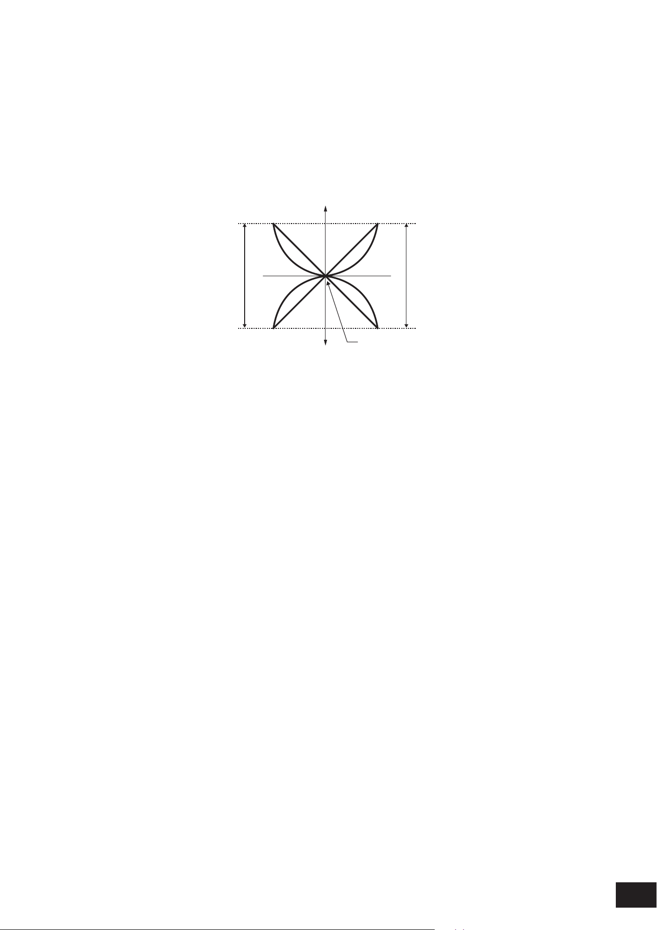
309
MODX M Operation Manual
Curve Lo (Level Scaling Low Curve)
Curve Hi (Level Scaling High Curve)
Sets the change curve for amplitude scaling.
Settings: −Linear, −Exp, +Exp, +Linear
The keyboard is divided in two at the Break Point. Set Curve Lo for the steepness of the curve on the left side, and Lvl/
Key Lo for the steepness of the curve on the right side. Similarly, set Curve Hi to select the curve for the right side, and
Lvl/Key Hi to the steepness of the curve.
Low Depth
Break Point Output Level
Low Curve High Curve
Key
High Depth
Output Level
−
+
+exp +exp+linear +linear
−exp −exp−linear −linear
The key at the Break Point is the same as the output level set in the Level (Operator Level).
With the keys on the left side of the Break Point, the output level is corrected to the curve set in Curve Lo and Lvl/Key Lo.
With the keys on the right side of the Break Point, the output level is corrected to the curve set in Curve Hi and Lvl/Key Hi.
The output level of Exp curves changes exponentially, while the output level of Linear curves changes linearly. In either
case, the farther away from the Break Point, the larger the changes to the output level.
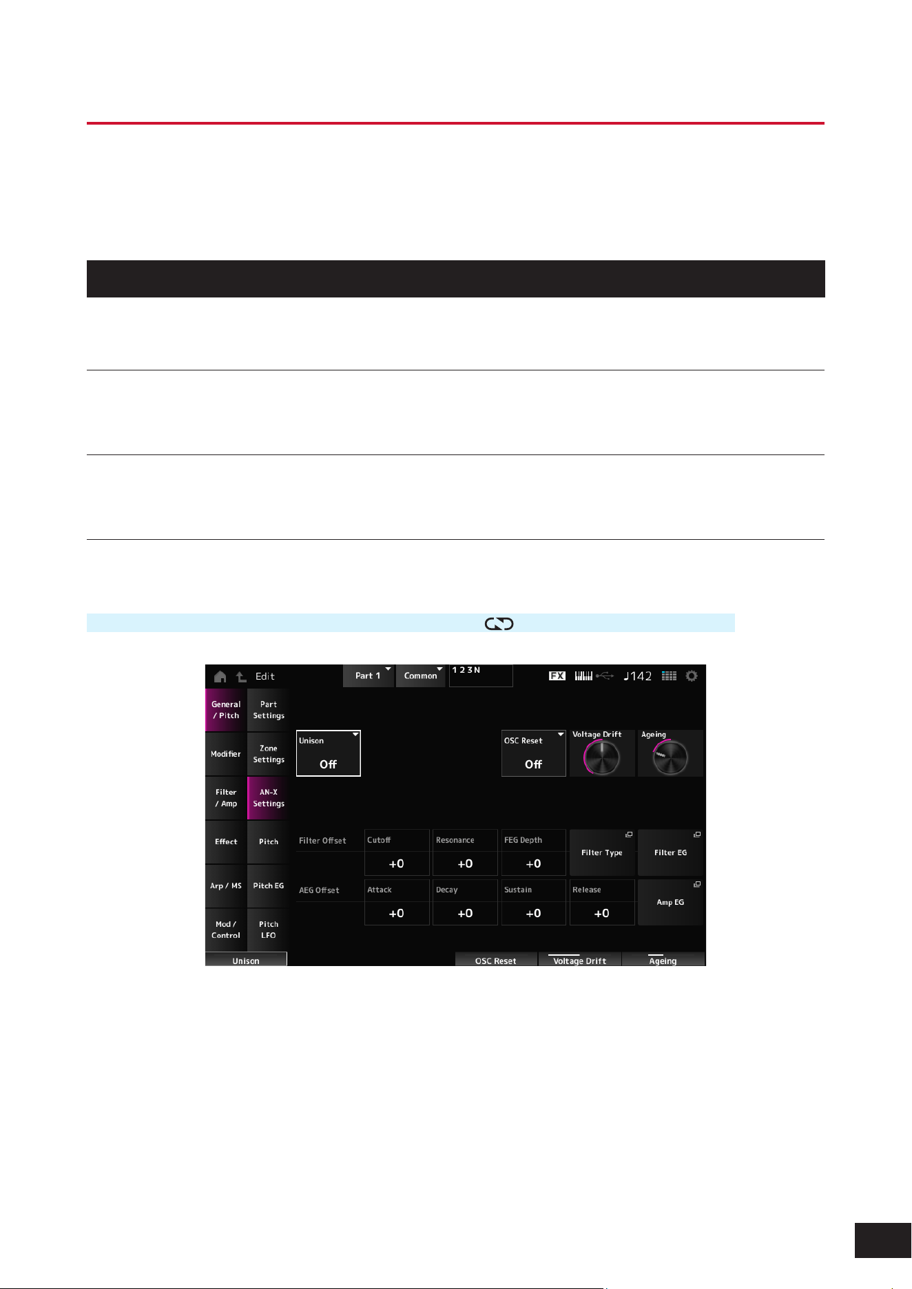
310
MODX M Operation Manual
Part Edit (AN-X) Part Common Edit Screens
The Normal Part (AN-X) consists of three Oscillators and Noise.
The Part Edit (AN-X) includes Part Common Edit for setting parameters for the entire Part, Oscillator Edit for setting
parameters for each Oscillator, and Noise Edit for editing Noise.
General/Pitch
Part Settings
The same as General/Pitch
→
Part Settings on the Part Edit (AWM2) Part Common Edit screen.
Zone Settings
The same as General/Pitch
→
Zone Settings on the Part Edit (AWM2) Part Common Edit screen.
AN-X Settings
On the AN-X Settings screen, you can set the parameters that are specic to the AN-X sound engine.
Operation
[PERFORMANCE (HOME)]
→
Part Common selection
→
[EDIT/ ]
→
General/Pitch
→
AN-X Settings
Unison
Creates thickness by layering multiple sounds.
Settings: Off, 2, 4
Unison Detune
Sets how the pitch of the layered sound is to be shifted.
Settings: 0–15
Unison Spread
Sets how the layered sounds are spread in the stereo eld.
Settings: 0–15
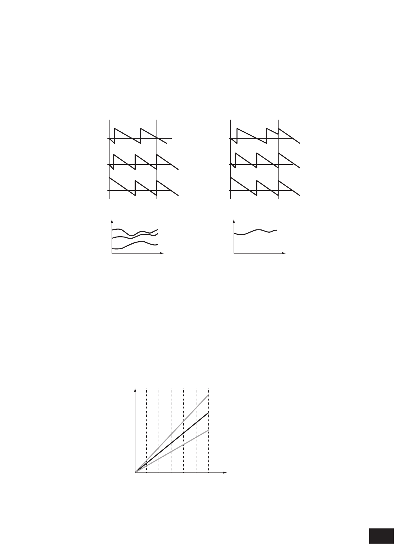
311
MODX M Operation Manual
OSC Reset
Species how to reset the Oscillator.
Settings: Off, Phase, Tune, Full
Off: Does not reset.
Phase: Resets the phase of OSC 1–3 at key-on.
Tune: Makes the pitch of OSC 1–3 uniform.
Full: Enables both Phase and Tune simultaneously
Amplitude
Osc 1
Osc 2
Osc 3
Key On
OSC Reset = Off or Tune
OSC Reset = Off or Phase
Amplitude
Osc 1
Osc 2
Osc 3
Key On
OSC Reset = Phase or Full
OSC Reset = Tune or Full
Osc 1
Osc 3
Osc 2
Pitch
t
Osc 1, 2, 3
Pitch
t
Voltage Drift
Species the pitch of the Oscillator and variation of Filter Cutoff. These variations are also affected by Ageing.
Settings: 0–127
0: No variation
64: Standard
127: Maximum variation
Ageing
Adjusts the frequency response as well as OSC Pitch, Filter Cutoff, and EG Time according to the virtual age of the
instrument model.
Settings: −100 (old) – +100 (new)
Voltage Drift and Ageing
(1)
210 43 64 85 107 128
Voltage Drift
Ageing = −100 (Retro)
Ageing = 0 (Default)
Ageing = 100 (Modern)
(1) Variations in Cutoff or Pitch

312
MODX M Operation Manual
Filter Offset Cutoff (Filter Cutoff Frequency)
Changes the sound by setting the cutoff frequency of the lter. When the Low Pass Filter is selected, larger values here
result in a brighter sound, and smaller values result in a darker sound.
This parameter is specied as an offset value to the lter cutoff frequency.
Settings: −64–+0–+63
Filter Offset Resonance (Filter Offset Resonance/Width)
Adds special characteristics to the sound by adjusting the signal level near the cutoff frequency.
This is specied as an offset value to the lter resonance.
Settings: −64–+0–+63
Filter Offset FEG Depth
Sets the depth range for the cutoff frequency change controlled by the FEG.
Settings: −64–+0–+63
Filter Type
The Filter Type screen will open.
Filter EG
The Filter EG screen will open.
AEG Offset Attack (AEG Attack Time)
Sets the length of time it takes for the volume to change from the moment you press a key on the keyboard to when it
reaches the maximum.
Sets the offset value to Attack (Amplitude EG Attack Time).
Settings: −64–+0–+63
AEG Offset Decay (AEG Decay Time)
Sets the length of time it takes for the volume to change after it has reached the maximum.
Sets the offset value to Decay (Amplitude EG Decay Time).
Settings: −64–+0–+63
AEG Offset Sustain (AEG Sustain Level)
Sets the volume that is maintained after the decay time.
Sets the offset value to Sustain (Amplitude EG Sustain Level).
Settings: −64–+0–+63
AEG Offset Release (AEG Release Time)
Sets the length of time it takes for the sound to decay after you have released the key.
Sets the offset value to Release (Amplitude EG Release Time).
Settings: −64–+0–+63
Amp EG
The Amp EG screen will open.
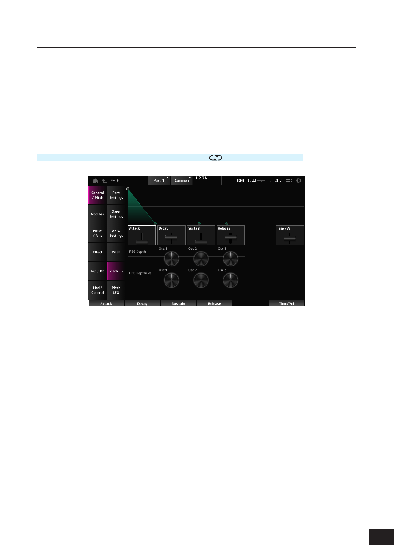
313
MODX M Operation Manual
Pitch
The screen here is the same as the one opened from General/Pitch
→
Pitch on the Part Edit (AWM2) Part Common Edit
screen, except that Legato Slope (Portamento Legato Slope) is disabled.
Pitch EG
On the Pitch EG screen, you can set the Pitch Envelope Generator.
You can use it to set how the sound changes over time, starting from the moment you press a key on the keyboard to when
the sound decays.
Operation
[PERFORMANCE (HOME)]
→
Part Common selection
→
[EDIT/ ]
→
General/Pitch
→
Pitch EG
Attack (Pitch EG Attack Time)
Sets the length of time it takes for the EG to change from the moment you press a key on the keyboard until it reaches the
maximum.
Settings: 0–255
Decay (Pitch EG Decay Time)
Sets the length of time it takes for the EG to change from the maximum to the Sustain (Pitch EG Sustain Level).
Settings: 0–255
Sustain (Pitch EG Sustain Level)
Sets the Sustain Level.
Settings: 0–511
Release (Pitch EG Release Time)
Sets the length of time it takes for the EG to reach a value of 0 after you have released the key.
Settings: 0–255
Time/Vel (Pitch EG Time Velocity Sensitivity)
Sets how the velocity changes the EG over time.
Larger the value the faster the changes of EG over time when the keys are played with fast velocity.
Settings: −255–+0–+255
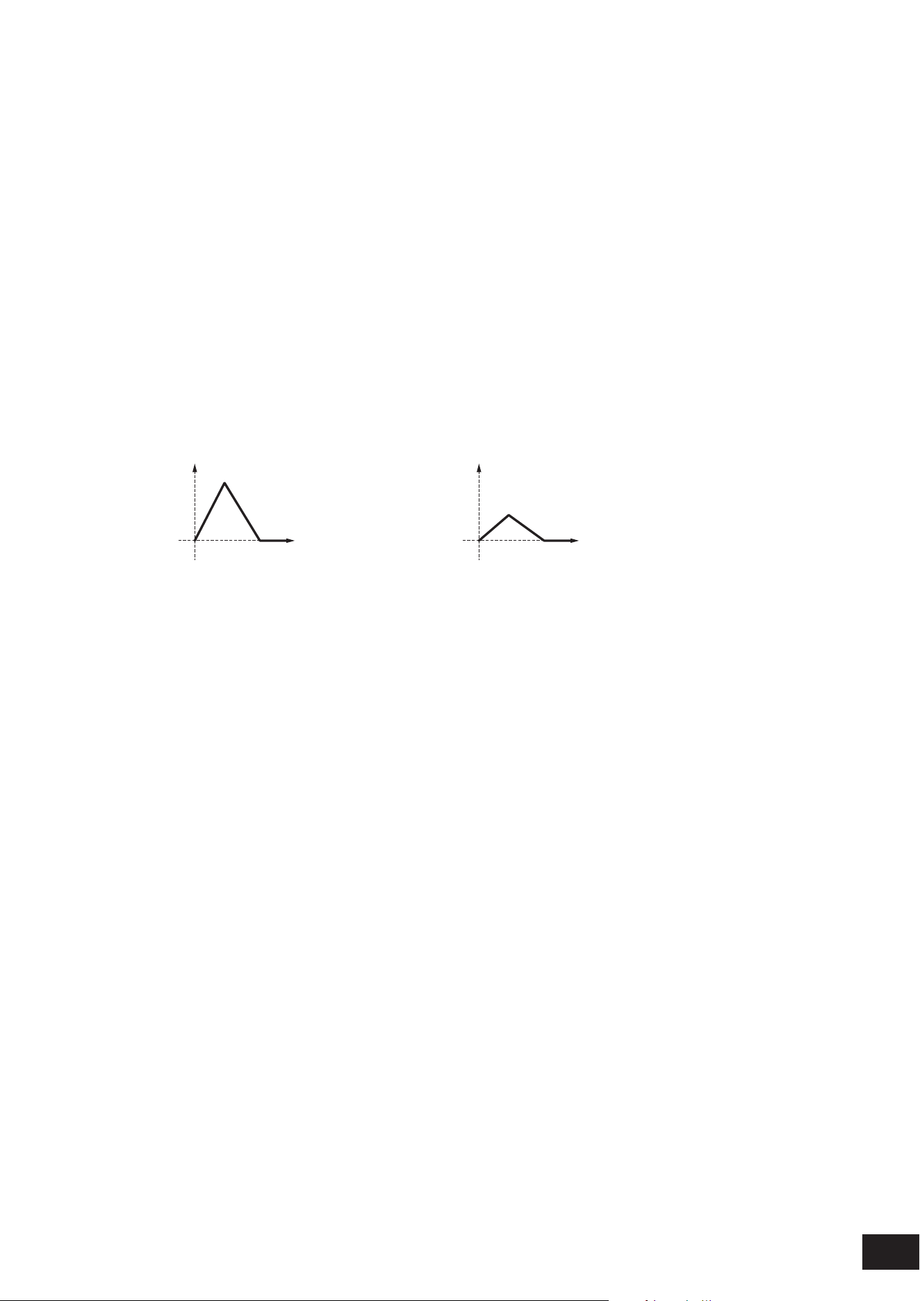
314
MODX M Operation Manual
PEG Depth - Osc 1–3 (Oscillator 1–3 Pitch EG Depth)
Sets the maximum amount of pitch change for the EG (in cents). The further the depth is from the value 0, the wider the
pitch change range becomes.
Settings: −4800 cent – +0 – +4800 cent
0: kept unchanged
Negative value: Pitch change is inverted.
PEG Depth/Vel - Osc 1–3 (Oscillator 1–3 Pitch EG Depth Velocity Sensitivity)
Sets how the depth range of the pitch change controlled by the PEG responds to Velocity or the strength of the keystroke.
Settings: −255–+0–+255
Positive value: Faster Velocity values widen the depth range of the pitch change controlled by the PEG, while slower values
narrow the depth range
0: No PEG changes regardless of the velocity setting.
Negative value: Faster Velocity values narrow the depth range of the pitch change controlled by the PEG, while slower
values widen the depth range
When the value is positive
Fast Velocity (the depth range in pitch change is wider) Slow Velocity (the depth range in pitch change is narrower)
Time
(1)
Time
(1)
(1) Pitch Depth
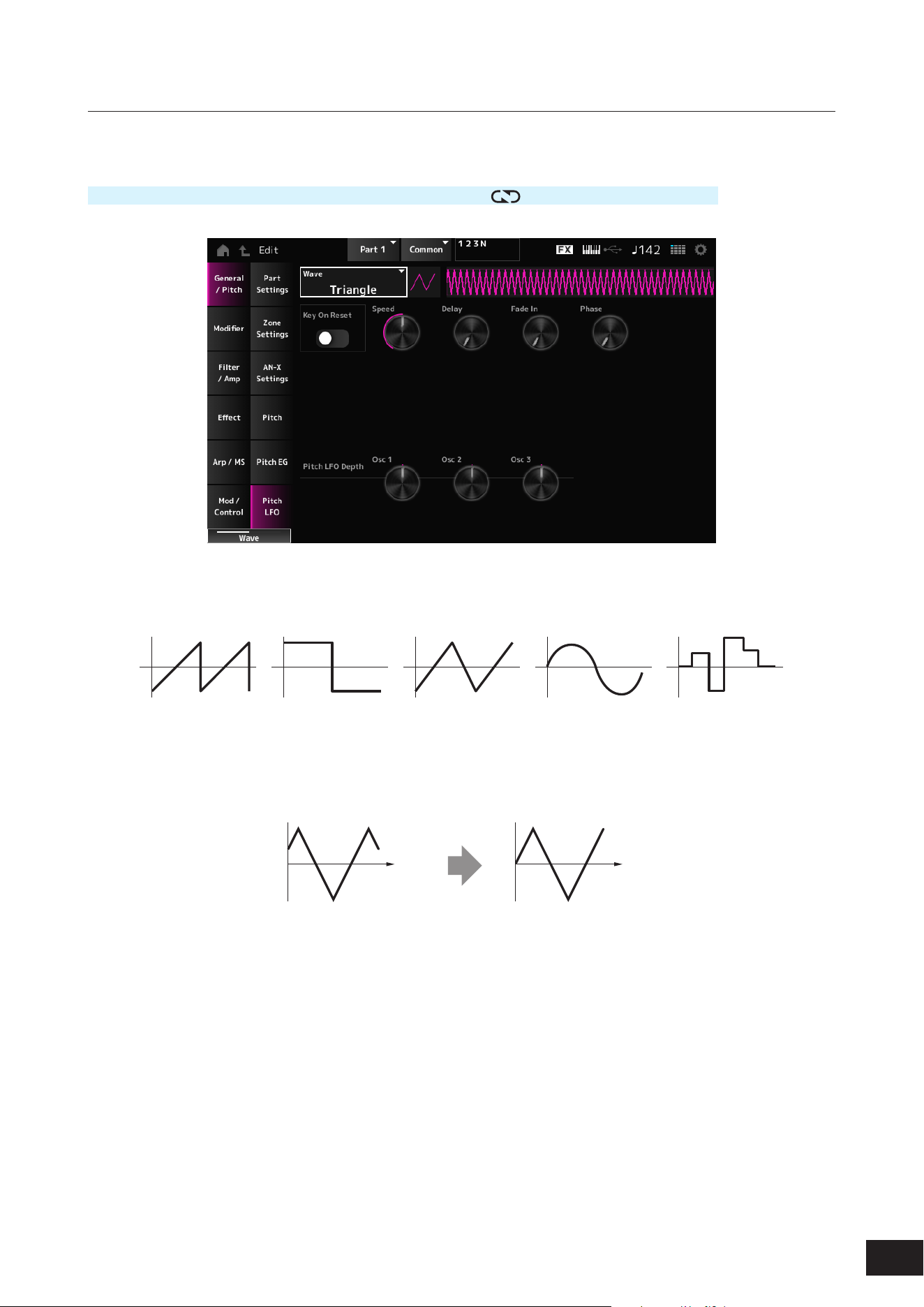
315
MODX M Operation Manual
Pitch LFO
On the Pitch LFO screen, you can set the Pitch LFO.
Operation
[PERFORMANCE (HOME)]
→
Part Common selection
→
[EDIT/ ]
→
General/Pitch
→
Pitch LFO
Wave (Pitch LFO Wave)
Selects the LFO Wave and sets the type of cyclical changes to the LFOs.
Settings: Saw, Square, Triangle, Sine, Random
Key On Reset (Pitch LFO Key On Reset)
Resets the phase of the LFO when a key is pressed.
Settings: Off, On
Time
Key on
Time
Key on
On
Off
Speed (Pitch LFO Speed)
Sets the speed of LFO wave changes.
Settings: 0–415
Delay (Pitch LFO Decay Time)
Sets the delay time between the moment you press a key on the keyboard and the moment the LFO comes into effect.
Settings: 0–127

316
MODX M Operation Manual
Fade In (Pitch LFO Fade In Time)
Sets the time length for the LFO effect to fade in after you have released the key and the delay time set in Delay has
elapsed. The larger the value, the longer it takes for the LFO effect to reach the maximum.
Settings: 0–214
0: The LFO changes to the maximum value without any fade-ins.
When the value is small
Fade In
Maximum
Delay
Key On
Time
When the value is large
Fade In
Maximum
Delay
Key On
Time
Phase (Pitch LFO Phase)
Sets the phase for resetting the wave when a key is pressed.
Settings: 0, 30, 45, 60, 90, 120, 135, 150, 180, 210, 225, 240, 270, 300, 315, 330(°)
Phase of the wave
Phase
Time
Level
0°
90°
120°
240°
180° 270°
Pitch LFO Depth - Osc 1–3 (Oscillator 1–3 Pitch LFO Depth)
Sets the depth range of pitch change controlled by the LFO. The further the depth is from the value 0, the wider the pitch
change range becomes.
Settings: −4800 cent – +0 – +4800 cent
0: kept unchanged
Negative value: Pitch change is inverted.
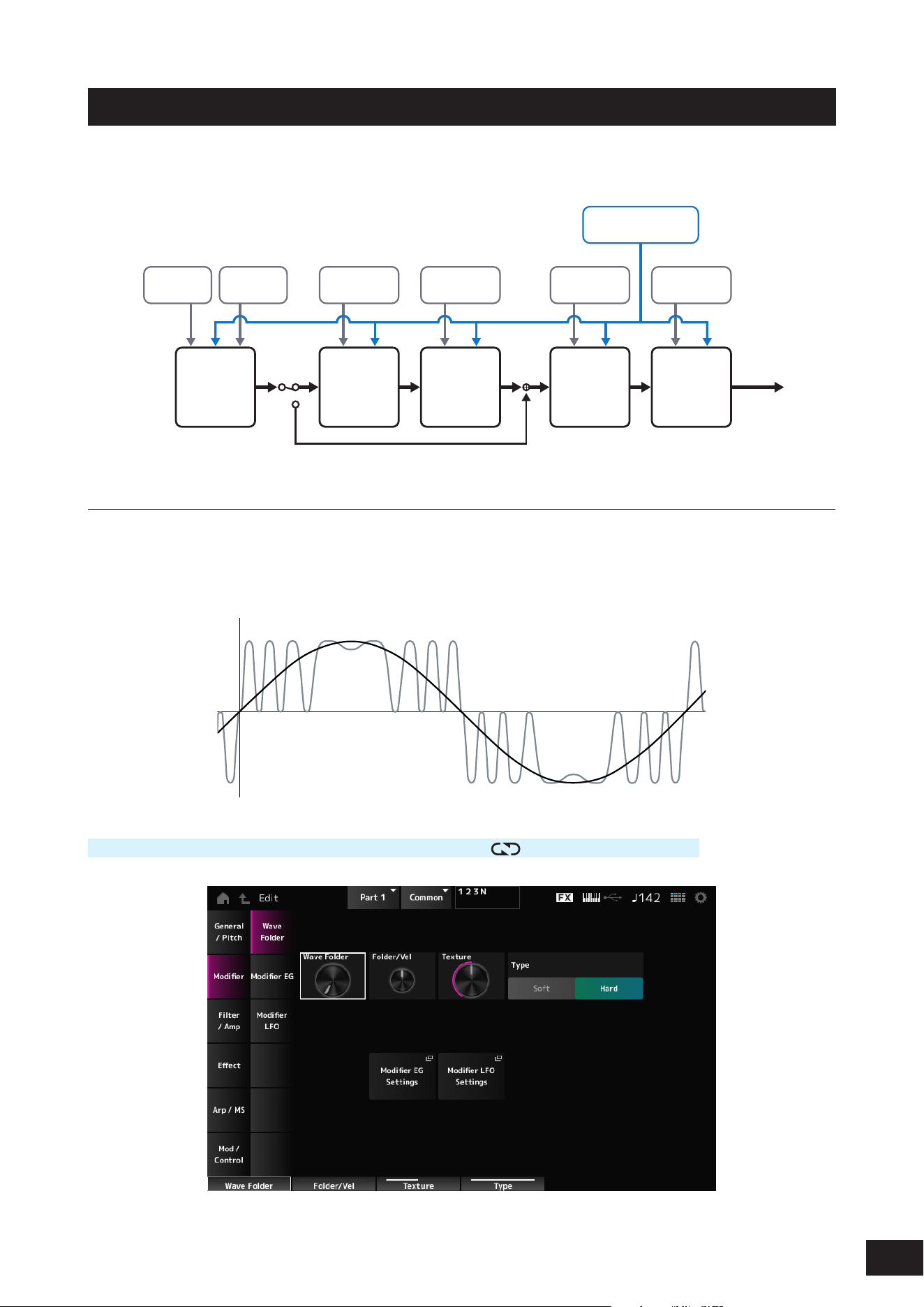
317
MODX M Operation Manual
Modifier
Modier is a function block for adding distortion to the signal output from the OSC block and for adding harmonics to the
sound.
Amp Effects
Motion Sequencer
Envelope Follower
Pitch EG
Pitch LFO
OSC EG
OSC LFO
Modifier EG
Modifier LFO
Filter EG
Filter LFO
Amp EG
Amp LFO
Part LFO
Oscillators Modifier Filters
Output
Wave Folder
Wave Folder is an effect created by folding waveforms according to the specied value. This effect lets you create smooth
changes from delicate distortion to sonic destruction. With the AN-X sound engine, you can use this effect on each note
independently.
Various controllers including EG, LFO, Velocity, and Polyphonic Aftertouch are available for controlling this effect in real-
time.
Operation
[PERFORMANCE (HOME)]
→
Part Common selection
→
[EDIT/ ]
→
Modier
→
Wave Folder

318
MODX M Operation Manual
Wave Folder (Modifier Wave Folder)
Species the degree of wave folding.
Settings: 0–255
Folder/Vel (Modifier Wave Folder Velocity Sensitivity)
Sets how the Wave Folder responds to Velocity.
Settings: −255–+0–+255
Texture (Modifier Wave Folder Texture)
Changes the texture of the Wave Folder.
Settings: 0–255
Folder Type (Modifier Wave Folder Type)
Changes the Wave Folder type.
Settings: Soft, Hard
Modifier EG Settings
The Modier EG screen will open.
Modifier LFO Settings
The Modier LFO screen will open.
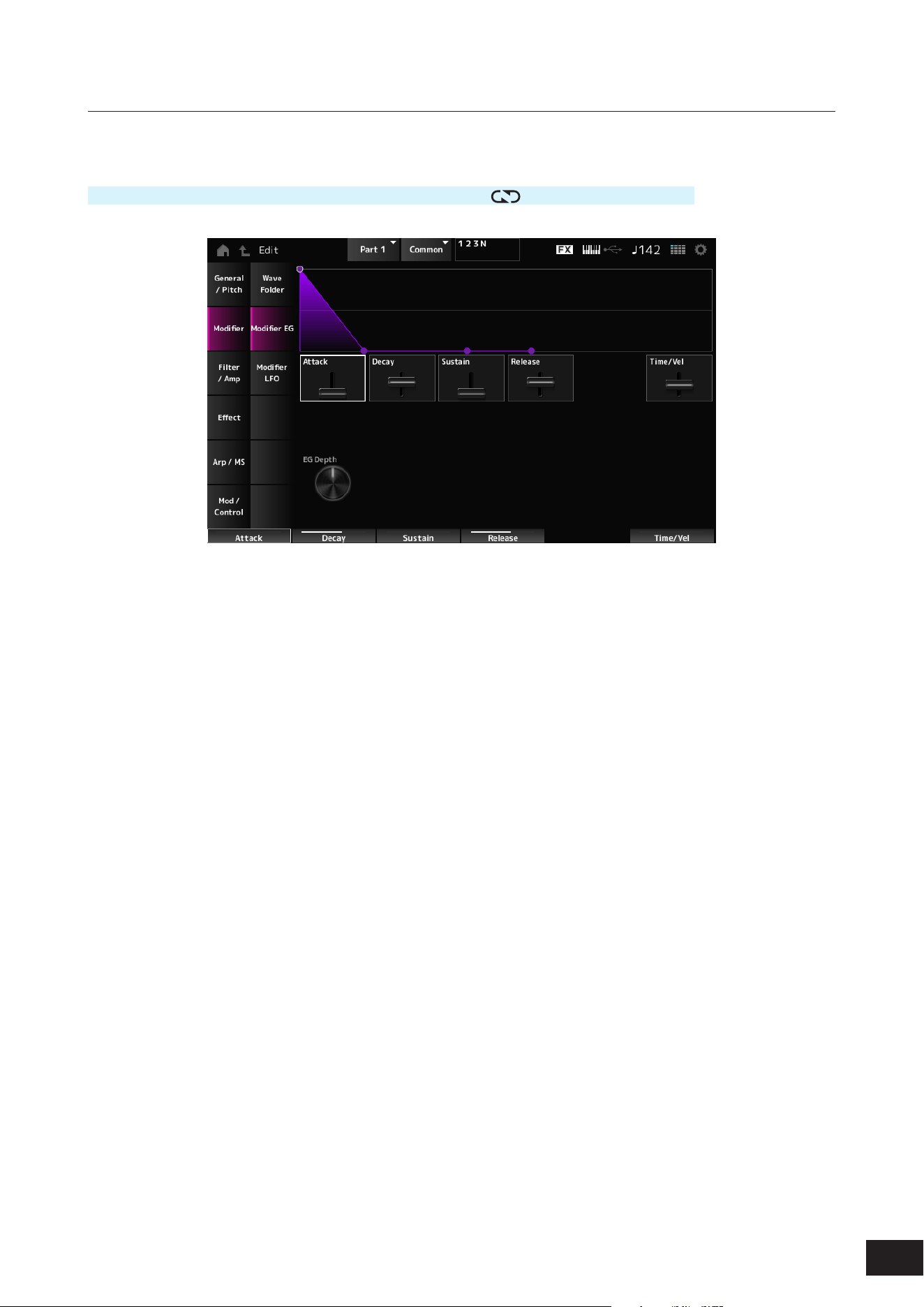
319
MODX M Operation Manual
Modifier EG
On the Modier EG screen, you can set the Envelope Generator for the Modier.
Operation
[PERFORMANCE (HOME)]
→
Part Common selection
→
[EDIT/ ]
→
Modier
→
Modier EG
Attack (Modifier EG Attack Time)
Sets the length of time it takes for the EG to change from the moment you press a key on the keyboard until it reaches the
maximum.
Settings: 0–255
Decay (Modifier EG Decay Time)
Sets the length of time it takes for the EG to change from the maximum to the Sustain (Modier EG Sustain Level).
Settings: 0–255
Sustain (Modifier EG Sustain Level)
Sets the Sustain Level.
Settings: 0–511
Release (Modifier EG Release Time)
Sets the length of time it takes for the EG to reach a value of 0 after you have released the key.
Settings: 0–255
Time/Vel (Modifier EG Velocity Sensitivity)
Sets how the velocity changes the EG over time.
Larger the value the faster the changes of EG over time when the keys are played with fast velocity.
Settings: −255–+0–+255
EG Depth (Modifier Wave Folder EG Depth)
Sets how the Wave Folder responds to Modier EG.
Settings: −127–+0–+127
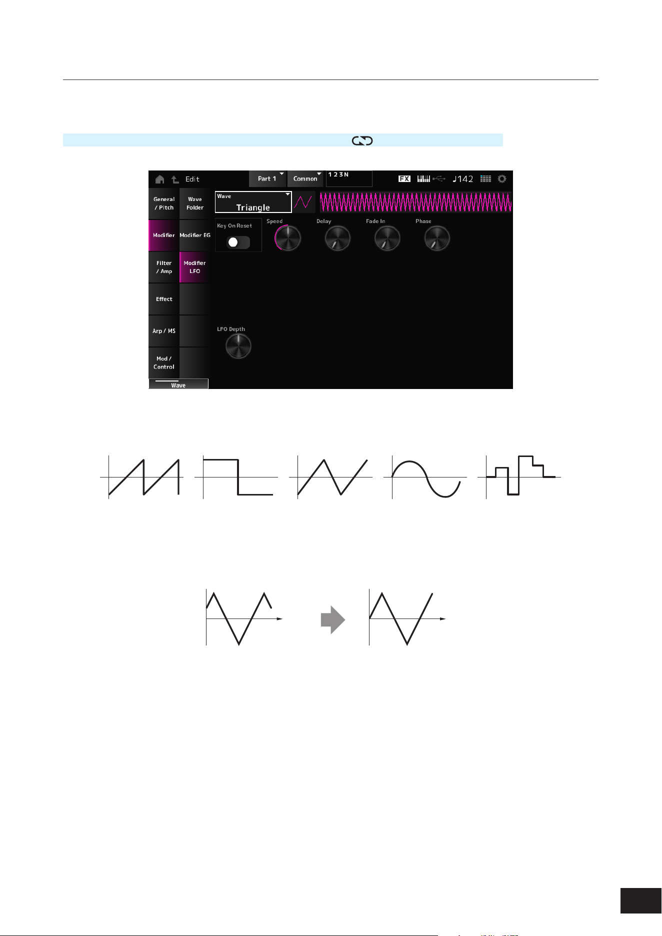
320
MODX M Operation Manual
Modifier LFO
On the Modier LFO screen, you can set the Modier LFO.
Operation
[PERFORMANCE (HOME)]
→
Part Common selection
→
[EDIT/ ]
→
Modier
→
Modier LFO
Wave (Modifier LFO Wave)
Selects the LFO Wave and sets the type of cyclical changes to the LFOs.
Settings: Saw, Square, Triangle, Sine, Random
Key On Reset (Modifier LFO Key On Reset)
Resets the phase of the LFO when a key is pressed.
Settings: Off, On
Time
Key on
Time
Key on
On
Off
Speed (Modifier LFO Speed)
Sets the speed of LFO wave changes.
Settings: 0–415
Delay (Modifier LFO Decay Time)
Sets the delay time between the moment you press a key on the keyboard and the moment the LFO comes into effect.
Settings: 0–127
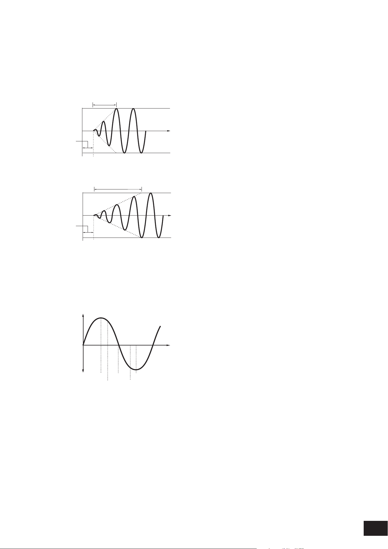
321
MODX M Operation Manual
Fade In (Modifier LFO Fade In Time)
Sets the time length for the LFO effect to fade in after you have released the key and the delay time set in Delay has
elapsed. The larger the value, the longer it takes for the LFO effect to reach the maximum.
Settings: 0–214
0: The LFO changes to the maximum value without any fade-ins.
When the value is small
Fade In
Maximum
Delay
Key On
Time
When the value is large
Fade In
Maximum
Delay
Key On
Time
Phase (Modifier LFO Phase)
Sets the phase for resetting the wave when a key is pressed.
Settings: 0, 30, 45, 60, 90, 120, 135, 150, 180, 210, 225, 240, 270, 300, 315, 330(°)
Phase of the wave
Phase
Time
Level
0°
90°
120°
240°
180° 270°
LFO Depth (Modifier Wave Folder LFO Depth)
Sets how the Wave Folder responds to Modier LFO. The further the depth is from the value 0, the wider the pitch change
range becomes.
Settings: −127–+0 –+127
0: kept unchanged
Negative value: Pitch change is inverted.
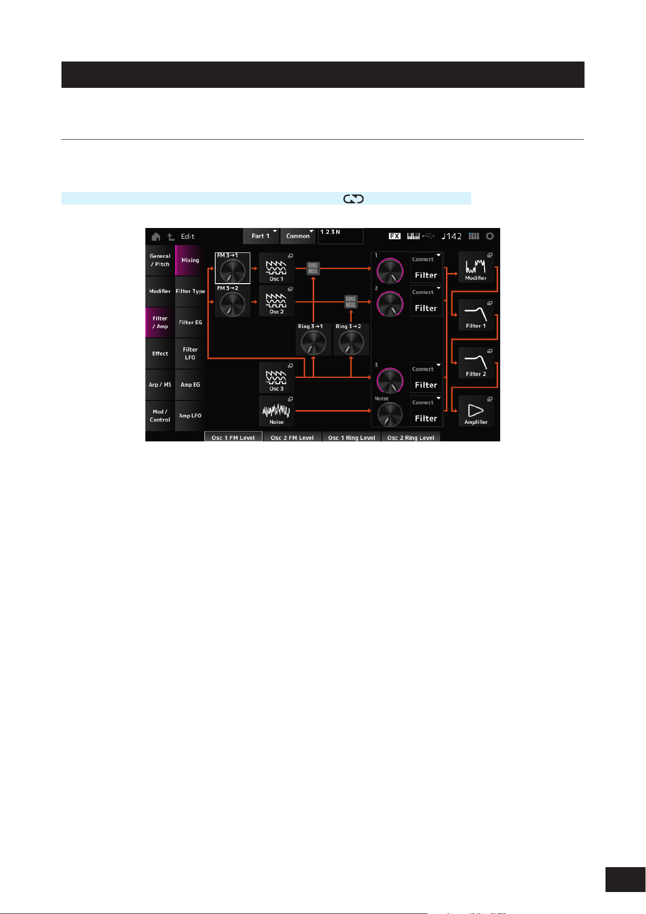
322
MODX M Operation Manual
Filter/Amp
Mixing
On the Mixing screen, you can set the output of each Oscillator while checking the signal ow diagram for the AN-X part.
Operation
[PERFORMANCE (HOME)]
→
Part Common selection
→
[EDIT/ ]
→
Filter/Amp
→
Mixing
FM 3
→
1 (Oscillator 1 FM Level)
FM 3
→
2 (Oscillator 2 FM Level)
Sets how OSC3 modulates OSC1 and OSC2 by using frequency modulation (FM).
Settings: 0–255
Osc 1 (Oscillator 1)
Osc 2 (Oscillator 2)
Osc 3 (Oscillator 3)
Opens the OSC/Tune screen for Oscillator Edit.
Noise
The Noise screen appears.
Useful for creating various SFX sounds by using lters such as VCF and HPF on the noise signals.
Ring 3
→
1 (Oscillator 1 Ring Level)
Ring 3
→
2 (Oscillator 2 Ring Level)
Sets how the OSC3 modulates OSC1 and OSC2 by using Ring Modulation.
Settings: 0–255
1 (Oscillator 1 Out Level)
2 (Oscillator 2 Out Level)
3 (Oscillator 3 Out Level)
Noise (Noise Out Level)
1, 2, and 3 are for setting the Oscillator volume.
Noise is for adjusting the level of the signal output from the Noise Unit. You can control the level balance with other signals
such as OSC 1, OSC 2, and Ring Modulator.
Settings: 0–511
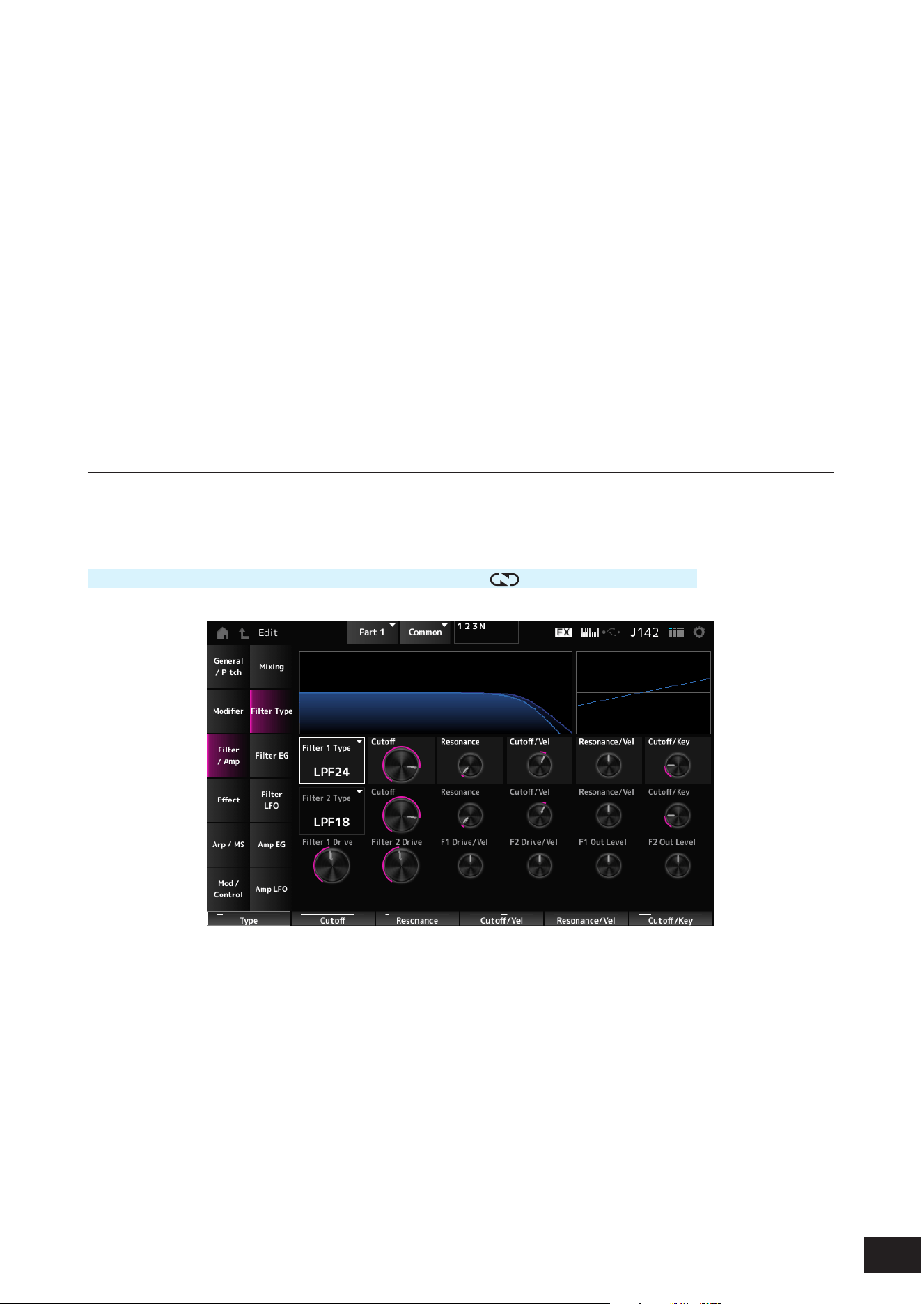
323
MODX M Operation Manual
Connect 1 (Oscillator 1 Out Select)
Connect 2 (Oscillator 2 Out Select)
Connect 3 (Oscillator 3 Out Select)
Noise Connect (Noise Out Select)
Sets the output destination for the Oscillators and Noise.
Settings: Filter, Amp
Modifier
Modier
→
Wave Folder is displayed.
Filter 1
Filter 2
Filter/Amp
→
Filter Type is displayed.
Amplifier
Filter/Amp
→
Amp EG is displayed.
Filter Type
On the Filter Type screen, you can select the lter type.
The available parameters differ depending on the lter type you have selected here.
Operation
[PERFORMANCE (HOME)]
→
Part Common selection
→
[EDIT/ ]
→
Filter/Amp
→
Filter Type
Filter 1 Type
Filter 2 Type
Sets the lter.
The lters available for the AN-X are grouped into three types: LPF, HPF, and BPF.
Settings: Thru, LPF24, LPF18, LPF12, LPF6, HPF24, HPF18, HPF12, HPF6, BPF12, BPF6
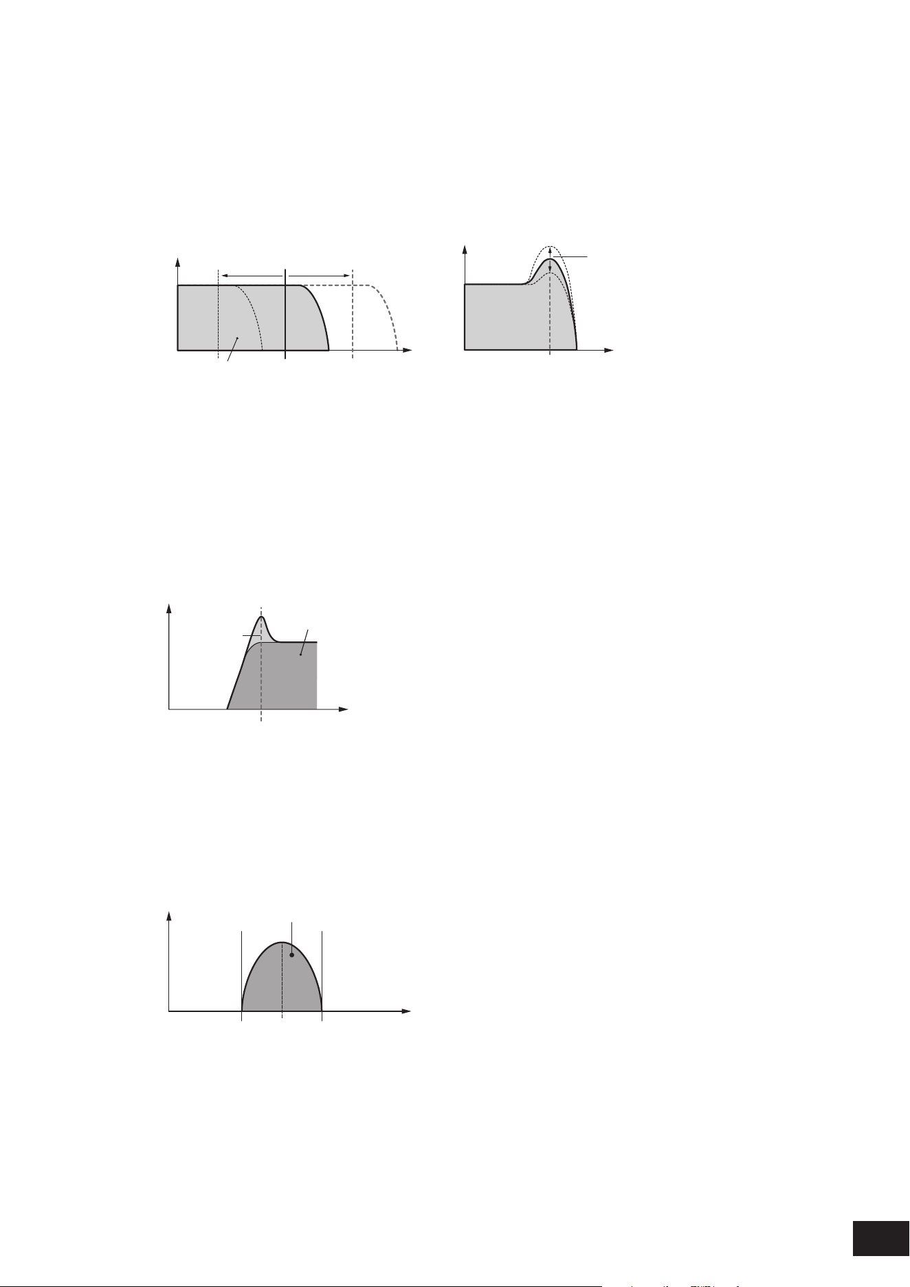
324
MODX M Operation Manual
• LPF
Cuts the signals above the value set in Cutoff Frequency. This is very popular and useful for producing classic
synthesizer sounds.
The sound becomes brighter as you raise the Cutoff Frequency, since more signals are passed by the lter.
The sound becomes darker as you lower the Cutoff Frequency, since signals are cut or blocked by the lter.
You can produce a distinctive “peaky” sound by raising the Resonance or boosting the signal level near the Cutoff
Frequency.
Frequencies that are
“passed” by the filter
Cutoff Frequency
Resonance
Frequency
Cutoff Frequency
Frequency
Gain
Gain
LPF24: −24 dB/oct
LPF18: −18 dB/oc
LPF12: −12 dB/oct
LPF6: −6 dB/oct
• HPF
A Filter Type that only passes signals above the Cutoff Frequency.
You can produce a distinctive “peaky” sound by raising the Resonance or boosting the signal level near the Cutoff
Frequency.
Resonance
Frequencies that are
“passed” by the filter
Frequency
Cutoff Frequency
Gain
HPF24: −24 dB/oct
HPF18: −18 dB/oct
HPF12: −12 dB/oct
HPF6: −6dB/oct
• BPF
A Filter Type that only passes signals for a specic frequency band (Cutoff Frequency) and cuts all other signals.
Frequencies that are “passed” by the filter
FrequencyCenter Frequency
Gain
BPF12: −12dB/oct
BPF6: −6dB/oct

325
MODX M Operation Manual
Cutoff (Filter Cutoff)
Sets the cutoff frequency. The frequency set here is used by the lter set in Filter Type.
Settings: 0–1023
Resonance (Filter Resonance)
Sets the size of the Resonance. This parameter may not be available depending on the Filter Type.
Settings: 0–255
Cutoff/Vel (Filter Cutoff Velocity Sensitivity)
Sets how Cutoff Frequency responds to Velocity or the strength of the keystroke.
Settings: −255–+0–+255
Positive value: The faster the Velocity, the higher the Cutoff Frequency value becomes
0: Cutoff frequency does not respond to the Velocity.
Negative value: The slower the Velocity, the higher the Cutoff Frequency value becomes
Resonance/Vel (Filter Resonance Velocity Sensitivity)
Sets how the resonance level responds to Velocity or the strength of the keystroke. This parameter may not be available
depending on the Filter Type.
Settings: −255–+0–+255
Positive value: The higher the Velocity, the greater the Resonance becomes
Negative value: The lower the Velocity, the greater the Resonance becomes
0: Resonance value does not change in response to Velocity.
Cutoff/Key (Filter Cutoff Key Follow)
Sets how the cutoff frequency level of the lter responds to the key position. When the value is set to 1oct, both the pitch
and the cutoff frequency change at the same rate.
Settings: Off, 1/3oct, 1/2oct, 2/3oct, 1oct, 2oct
Filter 1 Drive (Filter 1 Saturator Drive)
Filter 2 Drive (Filter 2 Saturator Drive)
Sets the amount of distortion controlled by the Saturator section of the lter.
Settings: 0.0 dB–60.0 dB (in units of 0.75 dB)
Filter 1 Drive/Vel (Filter 1 Saturator Drive Velocity Sensitivity)
Filter 2 Drive/Vel (Filter 2 Saturator Drive Velocity Sensitivity)
Sets how the Drive responds to Velocity.
Settings: −255–+0–+255
F1 Out Level (Filter 1 Out Level)
F2 Out Level (Filter 2 Out Level)
Sets the output level for the Filter.
Settings: −12.000 – +0.000 – +12.000 (dB) (in units of 0.375 dB)
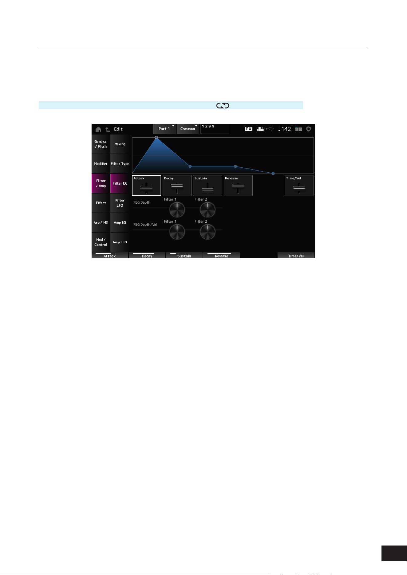
326
MODX M Operation Manual
Filter EG
On the Filter EG screen, you can set the Filter Envelope Generator (FEG).
The FEG lets you set the degree (or level) of changes to the Cutoff Frequency and how those changes evolve over time,
starting from the moment you press a key on the keyboard to the moment the sound decays.
Operation
[PERFORMANCE (HOME)]
→
Part Common selection
→
[EDIT/ ]
→
Filter/Amp
→
Filter EG
Attack (Filter Cutoff EG Attack Time)
Sets the length of time it takes for the EG to change from the moment you press a key on the keyboard until it reaches the
maximum.
Settings: 0–255
Decay (Filter Cutoff EG Decay Time)
Sets the length of time it takes for the EG to change from the maximum to the Sustain (Filter Cutoff EG Sustain Level).
Settings: 0–255
Sustain (Filter Cutoff EG Sustain Level)
Sets the Sustain Level.
Settings: 0–511
Release (Filter Cutoff EG Release Time)
Sets the length of time it takes for the EG to reach a value of 0 after you have released the key.
Settings: 0–255
Time/Vel (Filter Cutoff EG Time Velocity Sensitivity)
Sets how the Cutoff Frequency responds to Velocity or the strength of the keystroke.
Settings: −255–+0–+255
Positive value: The faster the velocity the faster the FEG changes
0: No changes regardless of the Velocity setting.
Negative value: Fast velocity values result in slower FEG changes, while slow velocity values result in faster FEG changes.
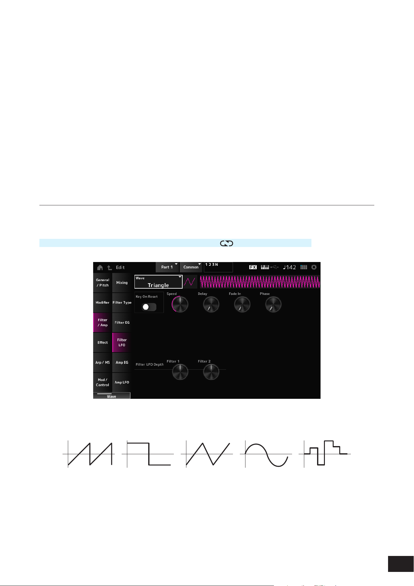
327
MODX M Operation Manual
FEG Depth - Filter 1–2 (Filter 1–2 Cutoff EG Depth)
Sets the depth range for the cutoff frequency change controlled by the FEG in 50 cent units. The depth range of the Cutoff
Frequency change becomes wider the further the setting is from a value of 0.
Settings: −9600 – +0 – +9600 (cent)
0: No changes to the cutoff frequency by the FEG
Negative value: Cutoff frequency changes are reversed.
FEG Depth/Vel - Filter 1–2 (Filter 1–2 Cutoff EG Depth Velocity Sensitivity)
Sets how the Cutoff Frequency controlled by the FEG responds to Velocity or the strength of the keystroke.
Settings: −255–+0–+255
Positive value: The faster the Velocity, the wider the depth range in Cutoff Frequency change by the FEG; the slower the
Velocity, the narrower the depth range
0: Cutoff frequency does not respond to the Velocity.
Negative value: The faster the Velocity, the narrower the depth range in Cutoff Frequency change by the FEG; the slower the
Velocity, the wider the depth range
Filter LFO
On the Filter LFO screen, you can set the Filter LFO.
Operation
[PERFORMANCE (HOME)]
→
Part Common selection
→
[EDIT/ ]
→
Filter/Amp
→
Filter LFO
Wave (Filter Common Cutoff LFO Wave)
Selects an LFO wave. By using the wave you have selected here, you can create various types of modulation.
Settings: Saw, Square, Triangle, Sine, Random
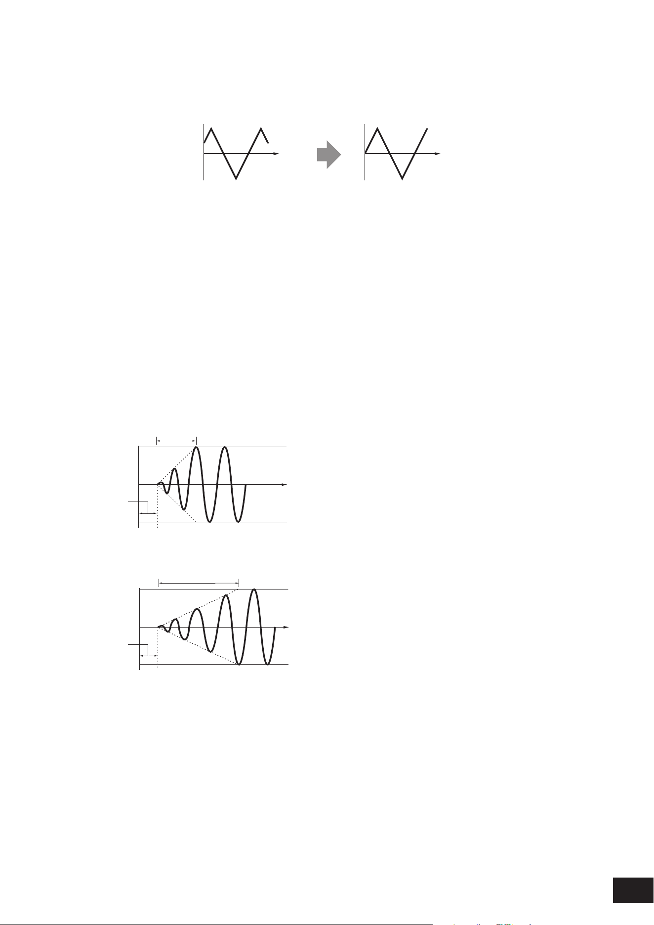
328
MODX M Operation Manual
Key On Reset (Filter Common Cutoff LFO Key On Reset)
Resets the oscillation of the LFO when a key is pressed.
Settings: Off, On
Time
Key on
Time
Key on
On
Off
Speed (Filter Common Cutoff LFO Speed)
Sets the speed of LFO wave changes.
Settings: 0–415
Delay (Filter Common Cutoff LFO Decay Time)
Sets the delay time between the moment you press a key on the keyboard and the moment the LFO comes into effect.
The larger the value, the longer the delay time for the LFO to come into effect.
Settings: 0–127
Fade In (Filter Common Cutoff LFO Fade In Time)
Sets the time length for the LFO effect to fade in after you have released the key and the delay time set in Delay has
elapsed. The larger the value, the longer it takes for the LFO effect to reach the maximum.
Settings: 0–214
0: The LFO changes to the maximum value without any fade-ins.
When the value is small
Fade In
Maximum
Delay
Key On
Time
When the value is large
Fade In
Maximum
Delay
Key On
Time
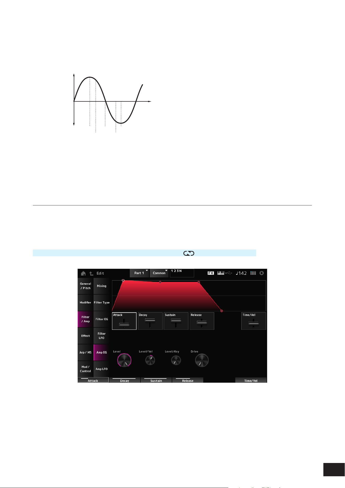
329
MODX M Operation Manual
Phase (Modifier LFO Phase)
You can set the initial phase for the time the LFO wave is reset.
Settings: 0, 30, 45, 60, 90, 120, 135, 150, 180, 210, 225, 240, 270, 300, 315, 330(°)
Phase of the wave
Phase
Time
Level
0°
90°
120°
240°
180° 270°
Filter LFO Depth - Filter 1–2 (Filter Cutoff LFO Depth)
Sets the depth of the LFO Wave control for Filter 1 and Filter 2 in 50 cent units.
Settings: −9600 – +0 – +9600 (cent)
Amp EG
On the Amp EG screen, you can set the AEG (Amplitude Envelope Generator).
By setting the Amp EG, you can set how the volume changes from the moment you press a key on the keyboard to when
the sound decays.
Operation
[PERFORMANCE (HOME)]
→
Part Common selection
→
[EDIT/ ]
→
Filter/Amp
→
Amp EG
Attack (Amplitude EG Attack Time)
Sets the length of time it takes from the moment you press a key on the keyboard to when the Level (Amplitude Level) is
reached.
Settings: 0–255

330
MODX M Operation Manual
Decay (Amplitude EG Decay Time)
Sets the length of time it takes for the volume to change from the Level (Amplitude Level) to the Sustain (Amplitude EG
Sustain Level).
Settings: 0–255
Sustain (Amplitude EG Sustain Level)
Sets the volume that is maintained while the key is held down.
Settings: 0–511
Release (Amplitude EG Release Time)
Sets the length of time it takes after you have release the key to when the sound decays.
Settings: 0–255
Time/Vel (Amplitude EG Time Velocity Sensitivity)
Sets the length of time it takes for volume changes in AEG to respond to Velocity or the strength of the keystroke.
Settings: −255–+0–+255
Positive value: The faster the velocity, the faster the AEG volume changes.
0: No changes regardless of the Velocity setting.
Negative value: Fast velocity values result in slower AEG volume changes, while slow velocity values result in faster AEG
volume changes.
Level (Amplitude Level)
Sets the volume level of Amplitude.
Settings: 0–511
Level/Vel (Amplitude Level Velocity Sensitivity)
Sets how the Amplitude level responds to Velocity.
Settings: −255–+0–+255
Level/Key (Amplitude Level Key Follow)
Sets how the Amp Level responds to pitch.
When Amplitude Level Key is set to 127, the Amp Level goes down 6 dB as the pitch goes up one octave.
Settings: 0–127
Drive (Amplitude Saturator Drive)
Sets the amount of distortion controlled by the Saturator of the Amplitude section.
Settings: 0.0 dB–60.0 dB (in units of 0.75 dB)
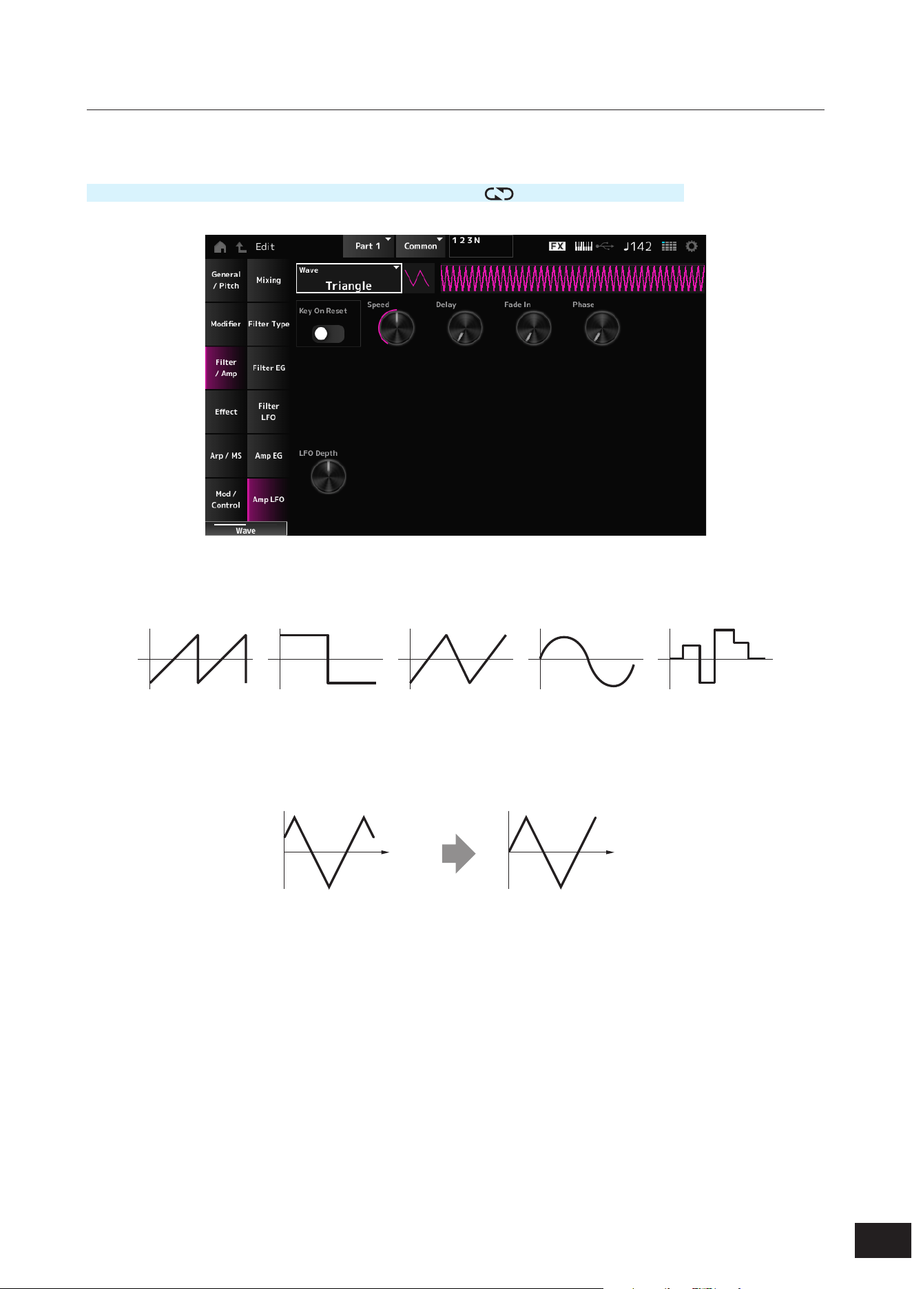
331
MODX M Operation Manual
Amp LFO
On the Amp LFO screen, you can set the Amplitude LFO.
Operation
[PERFORMANCE (HOME)]
→
Part Common selection
→
[EDIT/ ]
→
Filter/Amp
→
Amp LFO
Wave (Amplitude LFO Wave)
Selects an LFO wave. By using the wave you have selected here, you can create various types of modulation.
Settings: Saw, Square, Triangle, Sine, Random
Key On Reset (Amplitude LFO Key On Reset)
Resets the oscillation of the LFO when a key is pressed.
Settings: Off, On
Time
Key on
Time
Key on
On
Off
Speed (Amplitude LFO Speed)
Sets the speed of LFO wave changes.
Settings: 0–415
Delay (Amplitude LFO Decay Time)
Sets the delay time between the moment you press a key on the keyboard and the moment the LFO comes into effect.
The larger the value, the longer the delay time for the LFO to come into effect.
Settings: 0–127

332
MODX M Operation Manual
Fade In (Amplitude LFO Fade In Time)
Sets the time length for the LFO effect to fade in after you have released the key and the delay time set in Delay has
elapsed. The larger the value, the longer it takes for the LFO effect to reach the maximum.
Settings: 0–214
0: The LFO changes to the maximum value without any fade-ins.
When the value is small
Fade In
Maximum
Delay
Key On
Time
When the value is large
Fade In
Maximum
Delay
Key On
Time
Phase (Amplitude LFO Phase)
You can set the initial phase for the time the LFO wave is reset.
Settings: 0, 30, 45, 60, 90, 120, 135, 150, 180, 210, 225, 240, 270, 300, 315, 330(°)
Phase of the wave
Phase
Time
Level
0°
90°
120°
240°
180° 270°
Depth (Amplitude Level LFO Depth)
Sets the depth range of volume changes controlled by the LFO.
Settings: −127–+0–+127

333
MODX M Operation Manual
Effect
Routing
The screen here is almost the same as the one opened from Effect
→
Routing on the Part Edit (AWM2) Part Common Edit
screen, with the exceptions listed below.
• No output setting for each Element
• Cannot select Parallel for Ins Connect
Ins A, Ins B
The same as Effect
→
Ins A and Ins B on the Part Edit (AWM2) Part Common Edit screen.
3-band EQ
The same as Effect
→
3-band EQ on the Part Edit (AWM2) Part Common Edit screen.
2-band EQ
On the 2-band EQ screen, you can set the Part EQ. EQ can be set after the Insertion Effect.
Ins Assign
The same as Effect
→
Ins Assign on the Part Edit (AWM2) Part Common Edit screen.

334
MODX M Operation Manual
Arp/MS
Arp Common
The same as Arpeggio
→
Common on the Part Edit (AWM2) Part Common Edit screen.
Individual
The same as Arpeggio
→
Individual on the Part Edit (AWM2) Part Common Edit screen.
Advanced
The same as Arpeggio
→
Advanced on the Part Edit (AWM2) Part Common Edit screen.
MS Common
The same as Motion Seq
→
Common on the Part Edit (AWM2) Part Common Edit screen.
Lane
The same as Motion Seq
→
Lane on the Part Edit (AWM2) Part Common Edit screen.

335
MODX M Operation Manual
Mod/Control
Control Assign
Other than the Destination setting, the same as Mod/Control
→
Control Assign on the Part Edit (AWM2) Part Common
Edit screen.
Use the parameters shown below, instead of ElementSw and others.
Oscillator Sw (Oscillator Switch)
You can set the controller setting for each Oscillator on or off. This parameter is shown only when the selected Destination
is related to Oscillators.
Usually, there are three switches shown, but when the Destination is set to OSC FM or OSC Ring, only two of them will
be shown.
Settings: Off, On
Filter Sw
You can set the controller setting for each Filter on or off.
This parameter is shown only when the selected Destination is related to lters.
Settings: Off, On
After Touch
Other than the Destination setting, the same as Mod/Control
→
After Touch on the Part Edit (AWM2) Part Common Edit
screen.
Tx /Rx Switch
The same as Mod/Control
→
Tx/Rx Switch on the Part Edit (AWM2) Part Common Edit screen.
Control Settings
The same as Mod/Control
→
Control Settings on the Part Edit (AWM2) Part Common Edit screen.
Part LFO
The screen here is the same as the one opened from Mod/Control
→
Part LFO on the Part Edit (AWM2) Part Common
Edit screen, except that the only available Destination setting is Ins.
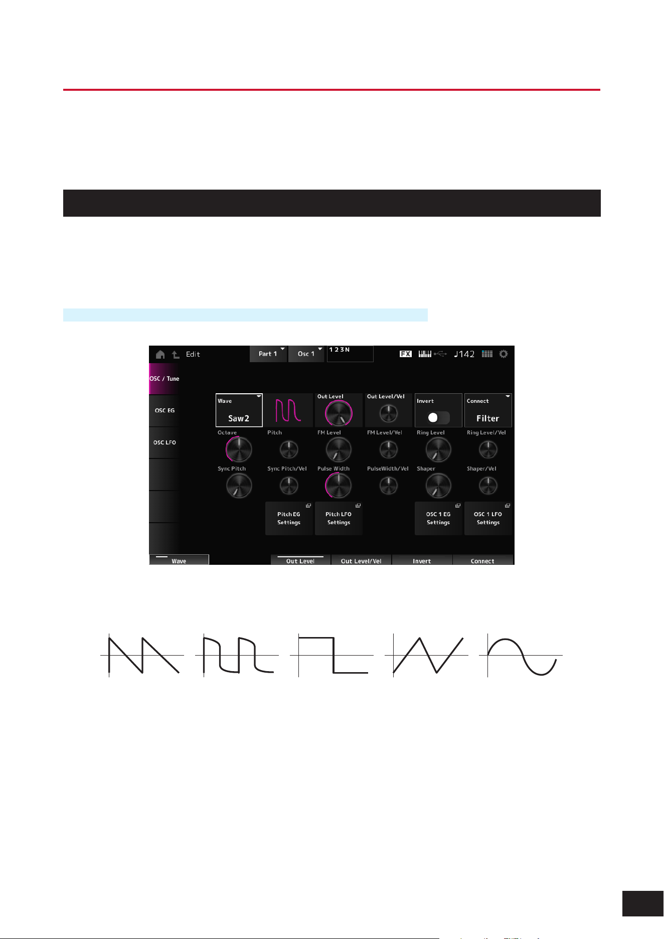
336
MODX M Operation Manual
Part Edit (AN-X) Oscillator Edit Screens
The Normal Part (AN-X) consists of three Oscillators and Noise.
The Part Edit (AN-X) includes Part Common Edit for setting parameters for the entire Part, Oscillator Edit for setting
parameters for each Oscillator, and Noise Edit for editing Noise.
Osc/ Tune
On the Osc/Tune screen, you can set the general parameters for the Oscillator.
The modulation and wave shaping functions available on this screen are FM (Frequency Modulation), Ring Modulation,
Oscillator Sync, Pulse Width, and Wave Shaper.
Operation
[PERFORMANCE (HOME)]
→
Part selection
→
Oscillator selection
→
Osc/ Tune
Wave (Oscillator Wave)
Sets the waveform for the Oscillator.
Settings: Saw1, Saw2 (variation of Saw1 with thicker sound), Square, Triangle, Sine
Out Level (Oscillator Out Level)
Sets the volume of the Oscillators.
Settings: 0–511
Out Level/Vel (Oscillator Out Level Velocity Sensitivity)
Sets how the Oscillator volume responds to Velocity.
Settings: −255–+0–+255

337
MODX M Operation Manual
Invert (Oscillator Out Invert Enable)
Performs negative/positive inversion of the Oscillator output.
Settings: Off, On
Connect (Oscillator Out Select)
Sets the output destination for the Oscillators.
Settings: Filter, Amp
Octave (Oscillator Octave)
Sets the pitch of the Oscillator in octaves.
Settings: 64’, 32’, 16’, 8’, 4’, 2’, 1’
Pitch (Oscillator Pitch)
Finely adjusts the pitch of the Oscillator.
Settings: −1200 – +0 – +1200(cent)
FM (Frequency Modulation)
Modulates the frequency of the Oscillator by using another Oscillator.
FM Level (Oscillator FM Level)
Sets the level of the Frequency Modulation.
Settings: 0–255
FM Level/Vel (Oscillator FM Level Velocity Sensitivity)
Sets how Frequency Modulation responds to Velocity.
Settings: −255–+0–+255
Ring Modulation
By mixing two Oscillator signals, you can create a metallic inharmonic sound.
Ring Level (Oscillator Ring Level)
Sets the level of Ring Modulation.
Settings: 0–255
Ring Level/Vel (Oscillator Ring Level Velocity Sensitivity)
Sets how Ring Modulation responds to Velocity.
Settings: −255–+0–+255
Oscillator Sync
Oscillator Sync is a system that creates complex waves by forcing two Oscillators to synchronize.
The AN-X sound engine allows each Oscillator to set its synchronization timing, so you can use a single Oscillator for
creating complex waveforms.
Sync Pitch (Oscillator Self Sync Pitch)
Sets the level of the Oscillator Sync in 25 cent units.
Settings: 0–4800 (cent)
Sync Pitch/Vel (Oscillator Self Sync Pitch Velocity Sensitivity)
Sets how Sync Pitch responds to Velocity.
Settings: −255–+0–+255

338
MODX M Operation Manual
Pulse Width
Pulse Width is the ratio of the negative and positive parts of the Square wave.
When Pulse Width is set to a small value When Pulse Width is set to 50% When Pulse Width is set to a large value
The AN-X sound engine lets you use Pulse Width not just on Square waves but also other waves.
Modulation of the LFO by using Pulse Width is called Pulse Width Modulation (PWM), which allows you to create a
characteristic swirling sound.
With the AN-X sound engine, you can use PWM by using Osc EG and Osc LFO. you can specify the level of PWM on the
Osc EG screen and Osc LFO screen.
Pulse Width (Oscillator Pulse Width)
Sets the Pulse Width of the wave.
Settings: 1.0%–50.0%–99.0%
PulseWidth/Vel (Oscillator Pulse Width Velocity Sensitivity)
Sets how Pulse Width responds to Velocity.
Settings: −255–+0–+255
Wave Shaper
Creates a characteristic distortion and changes to the harmonic content by changing the shape of the waveform.
Shaper (Oscillator Wave Shaper)
Sets the level of the Wave Shaper. By using Wave Shaper, the wave changes dynamically.
Settings: 0–255
Shaper/Vel (Oscillator Wave Shaper Velocity Sensitivity)
Sets how Wave Shaper responds to Velocity.
Settings: −255–+0–+255
Pitch EG Settings
General/Pitch
→
Pitch EG is shown on the Part Edit (AN-X) Part Common Edit screen.
Pitch LFO Settings
General/Pitch
→
Pitch LFO is shown on the Part Edit (AN-X) Part Common Edit screen.
Osc 1–3 EG Settings
The Osc EG screen appears.
Osc 1–3 LFO Settings
The Osc LFO screen appears.
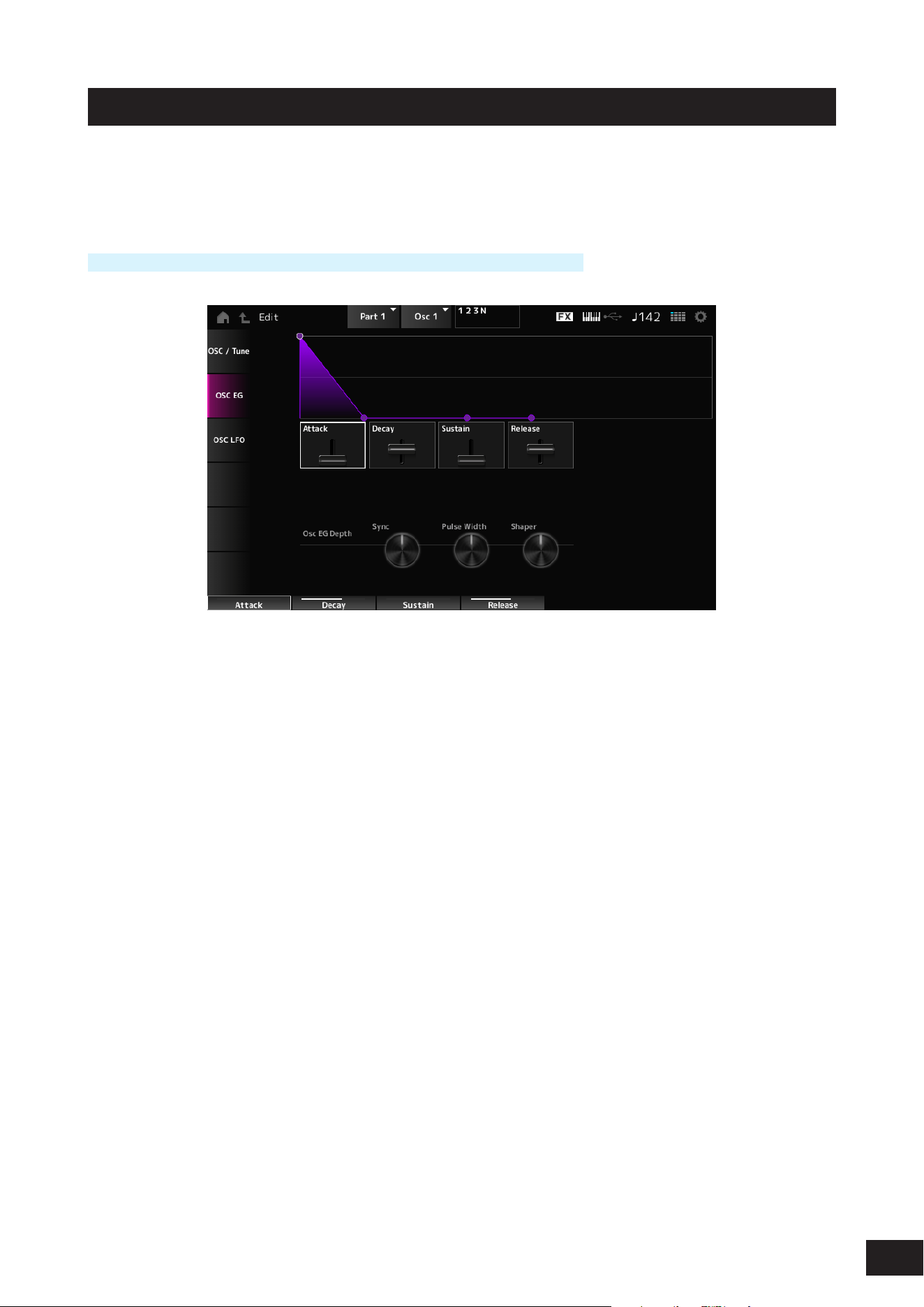
339
MODX M Operation Manual
Osc EG
On the Osc EG screen, you can set the Envelope Generator for the Oscillator.
You can set how the Sync, Pulse Width, and Wave Shaper change over time, starting from the moment you press a key
on the keyboard to when the sound decays.
Operation
[PERFORMANCE (HOME)]
→
Part selection
→
Oscillator selection
→
Osc EG
Attack (Oscillator EG Attack Time)
Sets the length of time it takes for the EG to change from the moment you press a key on the keyboard until it reaches the
value set at the Attack Level.
Settings: 0–255
Decay (Oscillator EG Decay Time)
Sets the length of time it takes for the EG to change from the moment you press a key on the keyboard until it reaches the
value set at the Decay Level.
Settings: 0–255
Sustain (Oscillator EG Sustain Level)
Sets the Sustain Level.
Settings: 0–511
Release (Oscillator EG Release Time)
Sets the length of time it takes for the EG to reach a value of 0 after you have released the key.
Settings: 0–255
Osc EG Depth Sync (Oscillator Self Sync EG Depth)
Sets how the Sync responds to Osc EG.
Settings: −4800 – +0 – +4800 (cent)
Osc EG Depth Pulse Width (Oscillator Pulse Width EG Depth)
Sets how the Pulse Width responds to Osc EG.
Settings: −127–+0–+127
Osc EG Depth Shaper (Oscillator Wave Shaper EG Depth)
Sets how the Shaper responds to Osc EG.
Settings: −127–+0–+127
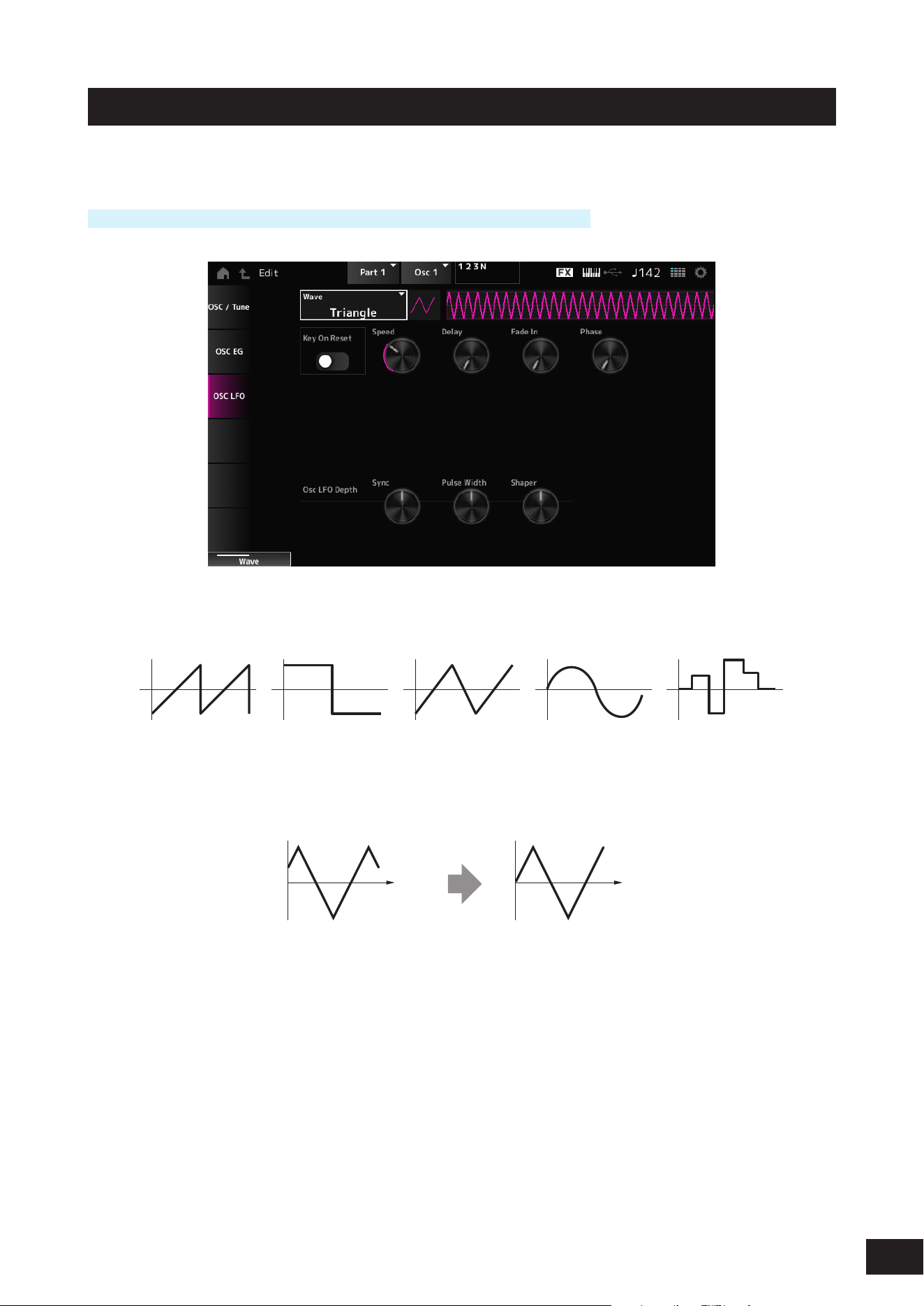
340
MODX M Operation Manual
Osc LFO
On the Osc LFO screen, you can set the Oscillator LFO.
Operation
[PERFORMANCE (HOME)]
→
Part selection
→
Oscillator selection
→
Osc LFO
LFO Wave (Oscillator LFO Wave)
Selects an LFO wave. By using the wave you have selected here, you can create various types of modulation.
Settings: Saw, Square, Triangle, Sine, Random
Key On Reset (Oscillator LFO Key On Reset)
Resets the oscillation of the LFO when a key is pressed.
Settings: Off, On
Time
Key on
Time
Key on
On
Off
Speed (Oscillator LFO Speed)
Sets the speed of LFO wave changes.
Settings: 0–415

341
MODX M Operation Manual
Delay (Oscillator LFO Delay Time)
Sets the delay time between the moment you press a key on the keyboard and the moment the LFO comes into effect.
Settings: 0–127
Fade In (Oscillator LFO Fade In Time)
Sets the time length for the LFO effect to fade in after you have released the key and the delay time set in Delay has
elapsed.
Settings: 0–214
Oscillator LFO Phase
Sets the LFO phase for resetting the wave when a key is pressed.
Settings: 0, 30, 45, 60, 90, 120, 135, 150, 180, 210, 225, 240, 270, 300, 315, 330(°)
Osc LFO Depth Sync (Oscillator Self Sync LFO Depth)
Sets how the Sync responds to Osc LFO.
Settings: −4800 – +0 – +4800 (cent)
Osc LFO Depth Pulse Width (Oscillator Pulse Width LFO Depth)
Sets how the Pulse Width responds to Osc LFO.
Settings: −127–+0–+127
Osc LFO Depth Shaper (Oscillator Wave Shaper LFO Depth)
Sets how the Shaper responds to Osc LFO.
Settings: −127–+0–+127
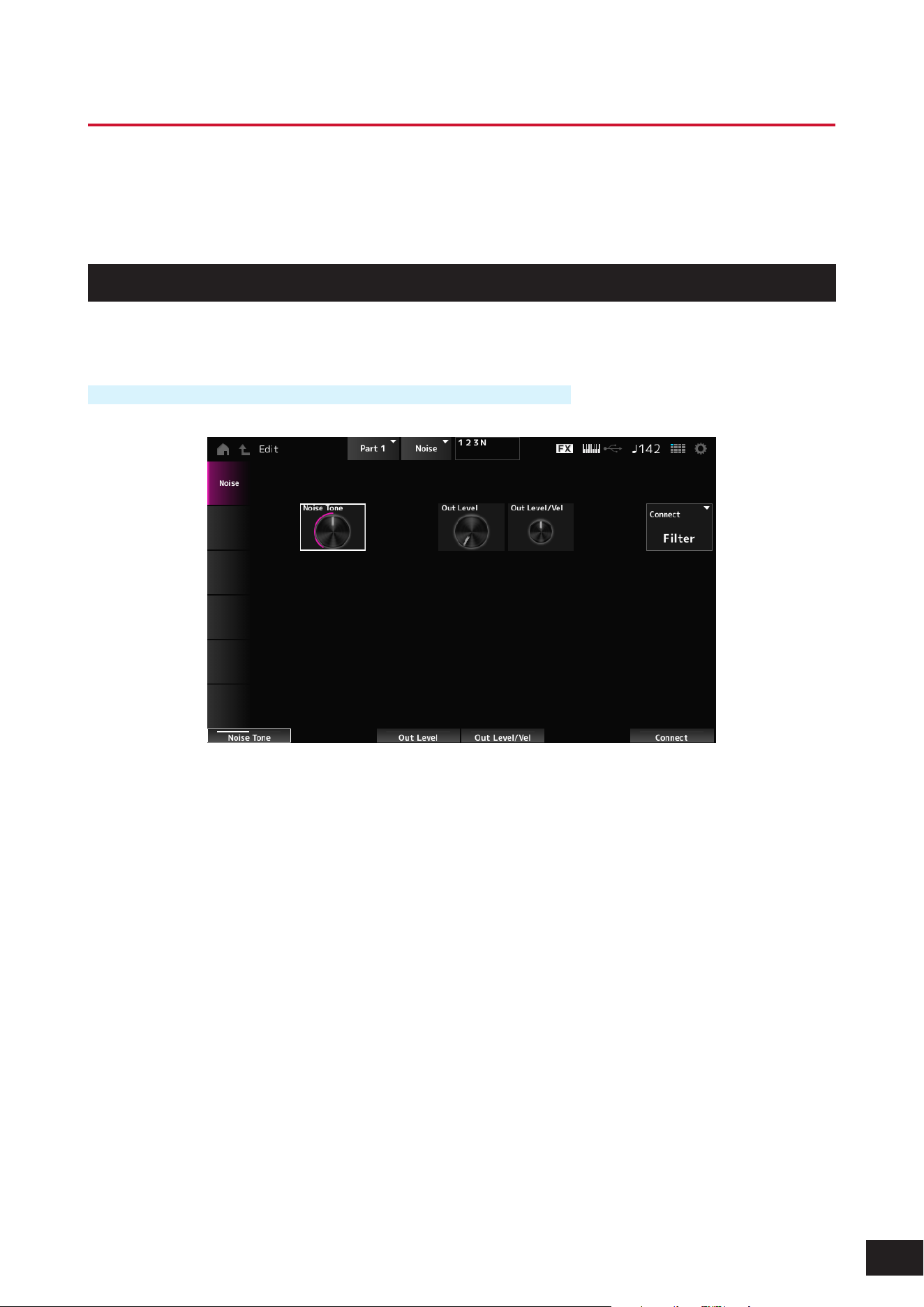
342
MODX M Operation Manual
Part Edit (AN-X) Noise Edit Screens
The Normal Part (AN-X) consists of three Oscillators and Noise.
The Part Edit (AN-X) includes Part Common Edit for setting parameters for the entire Part, Oscillator Edit for setting
parameters for each Oscillator, and Noise Edit for editing Noise.
Noise
On the Noise screen, you can set the Noise Generator.
Operation
[PERFORMANCE (HOME)]
→
Part selection
→
Oscillator selection
→
Noise
Noise Tone (Noise Generator Tone)
Sets the frequency response for the Noise.
Settings: 0–64–127
0–63: Cuts the treble
64: White noise
65–127: Cuts the bass
Out Level (Noise Generator Out Level)
Sets the volume of the Noise.
Settings: 0–511
Out Level/Vel (Noise Generator Out Level Velocity Sensitivity)
Sets how the Noise volume responds to Velocity.
Settings: −255–+0–+255
Connect (Noise Generator Out Select)
Sets the output destination for the Noise.
Settings: Filter, Amp
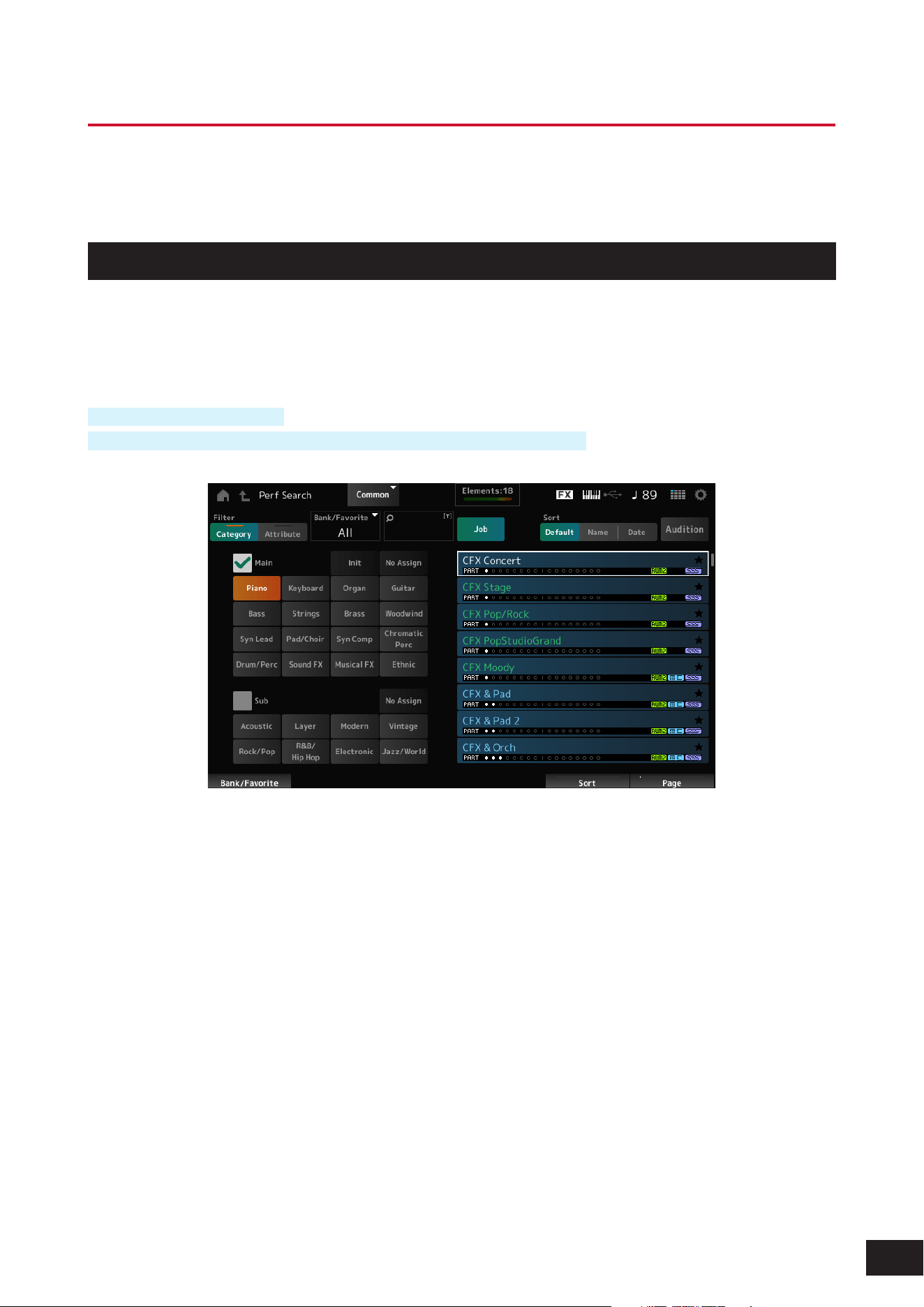
343
MODX M Operation Manual
Category Search Screens
Category Search is a convenient function that allows you to quickly nd a specic Performance, Part, Arpeggio, or
Waveform you wish to use from a specied category.
Performance Category Search
On the Performance Category Search screen, you can search for and select Performances.
While the Category Search screen is shown, you can use the buttons on the top panel to change the Part Select or Mute
settings.
Operation
Press the [CATEGORY] button
Tap the Performance name and select Category Search from the context menu
Filter
Select a lter to use in a search.
Settings: Category, Attribute
Main (Main Category)
Sub (Sub Category)
Filters by category.
By unchecking the Main or Sub checkbox, you can cancel ltering by category.
Settings: Refer to the Data List
Attribute
Filters by attribute.
By unchecking the Attribute checkbox, you can cancel ltering by attribute.
Settings: AWM2, FM-X, AN-X, MC, SSS, Smart Morph, Single, Multi, MOTIF XF, MONTAGE, MODX M OS V1.0

344
MODX M Operation Manual
Bank/Favorite (Bank/Favorite Select)
Filters by bank or Favorites.
When Favorite is selected, only the Performances with Favorite Flags will appear in the list.
When the Category Search screen is shown, you can press the [CATEGORY] button to switch the Bank in the order of All
→
Favorite
→
Preset
→
User
→
Library name (when a Library le is loaded).
When you hold down the [CATEGORY] button, the selection will be reset to All.
Settings: All, Favorite, Preset, User, Library name (when a Library le is loaded)
Name Search
Allows you to enter certain characters included in the name for easy searching. You can use up to 20 alphanumeric
characters.
Job
Calls up the Job menu.
• Delete
Deletes the selected content.
This parameter is available only when a Performance in the User Bank is selected.
• Rename
Changes the name of the selected content.
This parameter is available only when a Performance in the User Bank is selected.
• Favorite All Clear
Clears all Favorite Flags from the Performances.
This parameter is not available when there are no Performances with Favorite Flags.
Sort
Sets the sort order of the Performance list.
Settings: Default, Name, Date
Name: Sorts by name. The down arrow indicates that the list is arranged in ascending order (A to Z). The up arrow indicates
that the list is arranged in descending order.
Date: Sorts by date the setting was stored. The down arrow indicates that the list is arranged in descending order (new to old).
The up arrow indicates that the list is arranged in ascending order.
Audition
Sets the audition phrase playback on or off.
This parameter is not available when Audition Lock is set to On at [UTILITY]
→
Settings
→
Advanced.
Settings: Off, On
Performance list
Shows the Performance name, along with its active Parts, attributes, and Favorite Flag status.
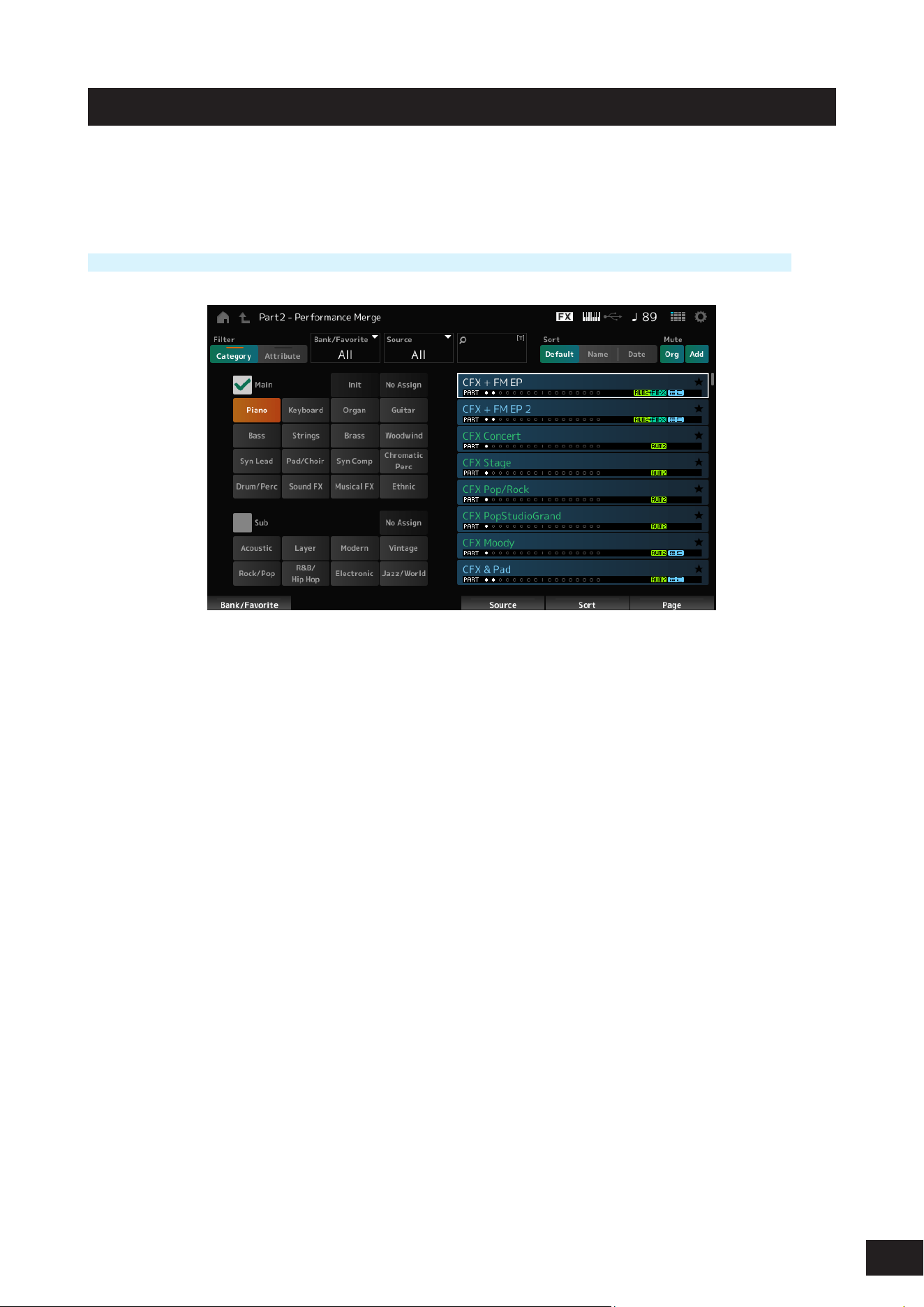
345
MODX M Operation Manual
Performance Merge
The Performance Merge screen allows you to assign multiple Parts of the selected Performance to empty Parts of
another Performance. For example, you can layer a four-Part piano Performance and a two-part string Performance to
create a rich six-part Performance.
Operation
[PERFORMANCE (HOME)]
→
Part selection (if the selected Part and all subsequent Parts are empty)
→
Tap [+]
Source
When selecting a Performance, the sound of the Part specied here is assigned to the currently selected Part.
Settings: All, Part 1–16
All: All Parts in the selected Performance are assigned to empty Parts of the other selected Performance (as much as
possible).
Part 1–16: Only the sound of the specied Part will be assigned to the other selected Part
Mute Org (Original Part Mute)
When this is set to Off, the Parts that were displayed before the Performance Merge screen was opened will be muted.
Settings: Off, On
Mute Add (Additional Part Mute)
When this is set to Off, the Parts added on the Performance Merge screen will be muted.
Settings: Off, On
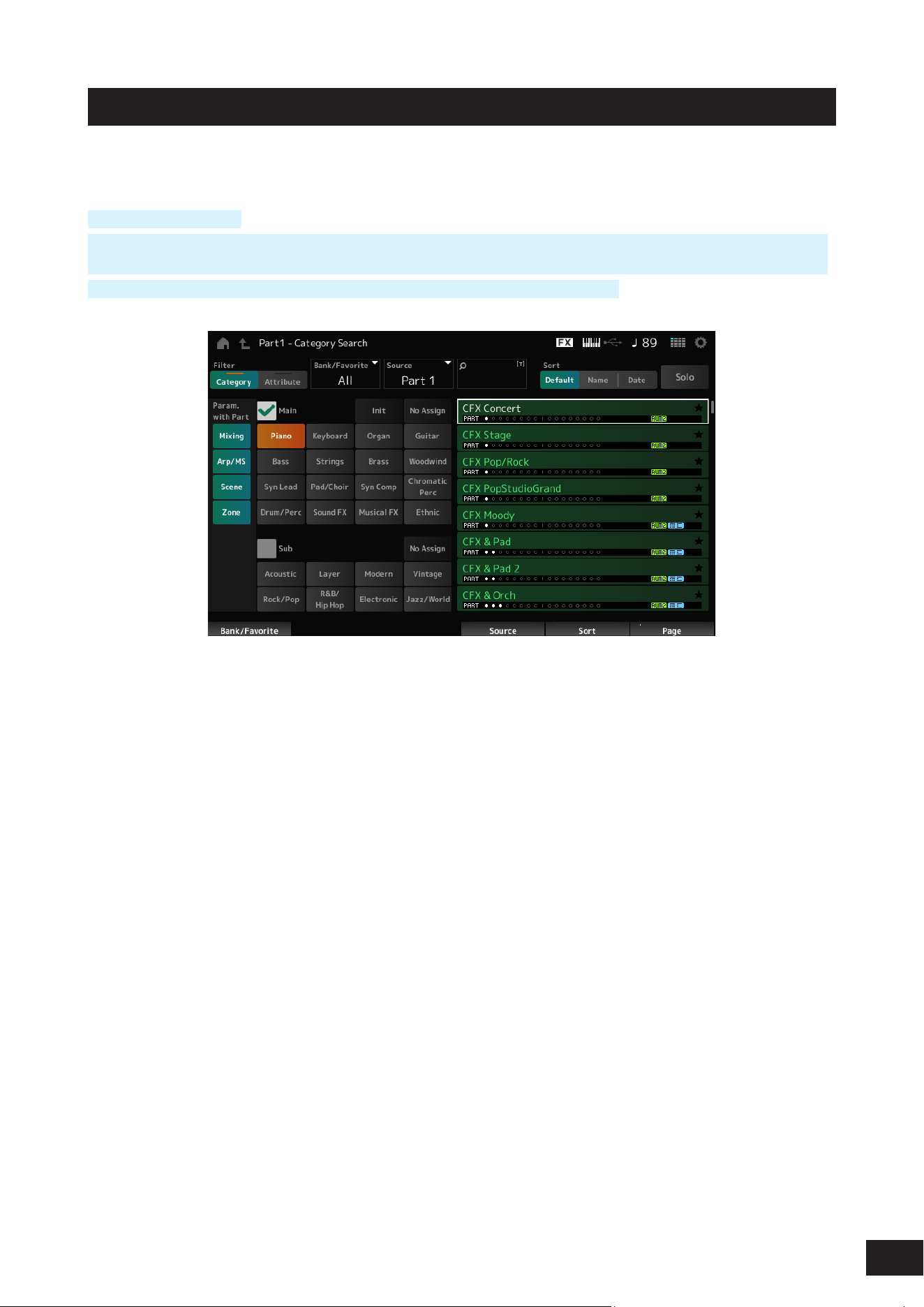
346
MODX M Operation Manual
Part Category Search
On the Part Category Search screen, you can search for and select Parts.
Operation
[SHIFT] + [CATEGORY]
(When selecting a Part to which a sound has already been assigned) Tap the Performance name and select Category
Search from the context menu
(When selecting an empty Part to which a sound has already been assigned) Tap [+]
Source (Source Part)
When selecting a Performance, the sound of the Part specied here is assigned to the currently selected Part.
The initial setting is Part 1.
Settings: Part 1–16
Solo
Sets the Solo function on or off.
When this switch is turned On, the selected Part is set to solo.
Settings: Off, On
Param. with Part (Parameter with Part)
Loads a group of parameter values when a Performance is selected.
The parameter groups set to Off will retain their current settings even when a new Performance is selected.
Parameter groups: Mixing, Arp/MS, Scene, Zone
Settings: Off, On
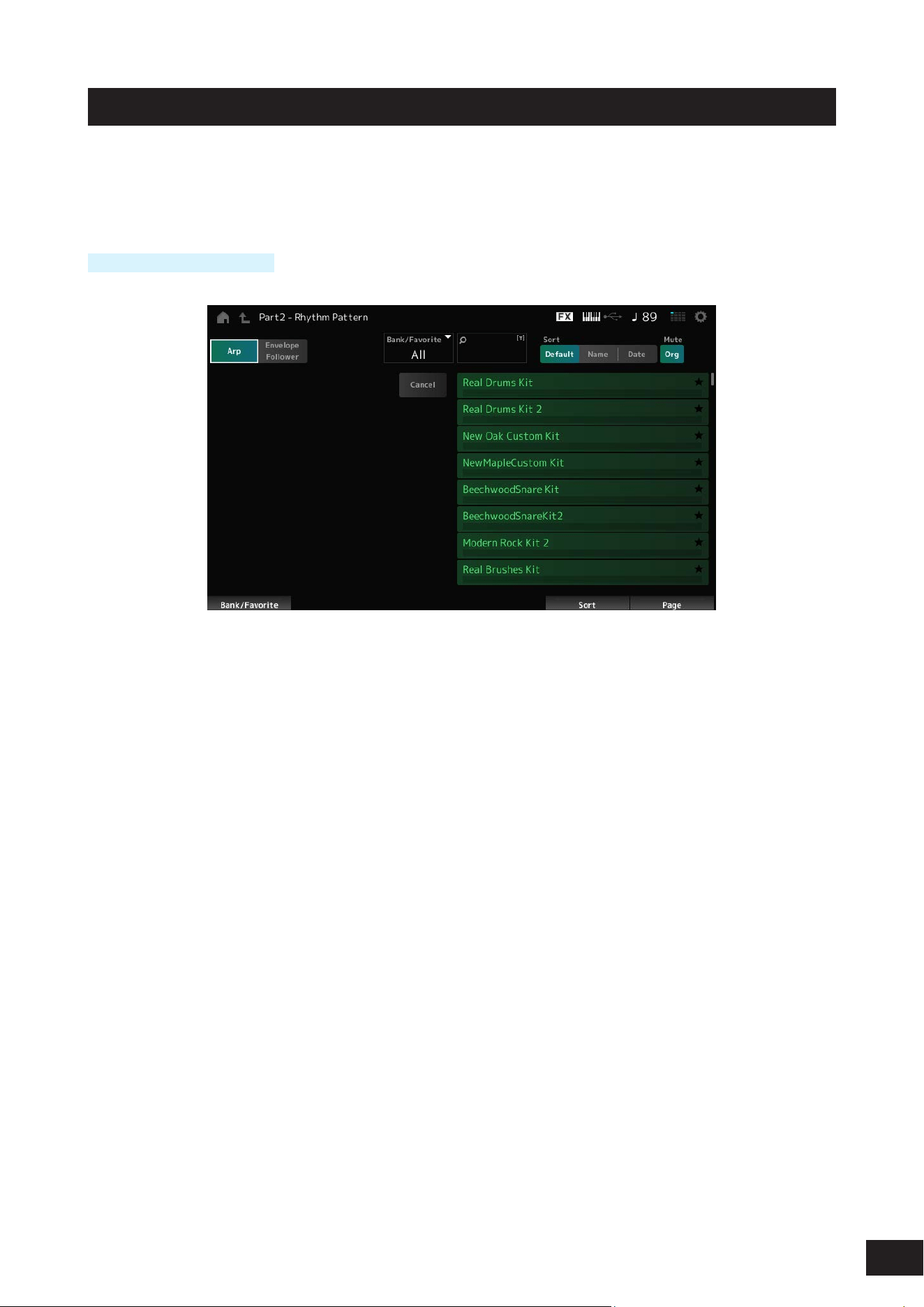
347
MODX M Operation Manual
Rhythm Pattern
On the Rhythm Pattern screen, you can search for and select Rhythm Patterns.
The Rhythm Pattern function allows you to instantly add a rhythm Part to the current Performance. Also, by combining
Rhythm Patterns with envelope follower effects, you can further change the sound.
Operation
[SHIFT] + [SONG/PATTERN]
Arp (Arpeggio)
Envelope Follower
Selects Arpeggio display or Envelope Follower display.
Bank/Favorite (Bank/Favorite Select)
Filters by bank or Favorites.
When Favorite is selected, only the Rhythm Patterns with Favorite Flags will appear in the list.
Settings: All, Favorite, Preset, User, Library name (when a Library le is loaded)
Name Search
Allows you to enter certain characters included in the name for easy searching. You can use up to 20 alphanumeric
characters.
Sort
Sets the sort order of the Rhythm Pattern list.
Settings: Default, Name, Date
Name: Sorts by name. The down arrow indicates that the list is arranged in ascending order (A to Z). The up arrow indicates
that the list is arranged in descending order.
Date: Sorts by date the setting was stored. The down arrow indicates that the list is arranged in descending order (new to old).
The up arrow indicates that the list is arranged in ascending order.
Mute Org (Original Part Mute)
When this is set to Off, the Parts that were displayed before the Rhythm Pattern screen was opened will be muted.
Settings: Off, On
Mute Add (Additional Part Mute)
When this is set to Off, the Parts added on the Rhythm Pattern screen will be muted.
Settings: Off, On
Rhythm Pattern list
Shows the Rhythm Pattern list.
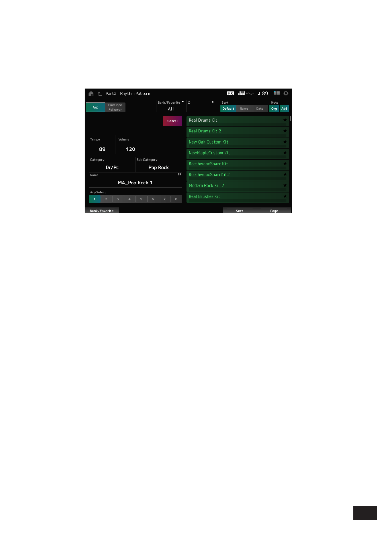
348
MODX M Operation Manual
Cancel
Cancels the operation.
When Arp is set to On
Frequently used parameters for Arpeggio settings are displayed on the left side of the screen.
Tempo
Sets the tempo.
Settings: 5–300
Volume
Sets the volume of the Rhythm Pattern.
Settings: 0–127
Category (Arpeggio Main Category)
Sub Category (Arpeggio Sub Category)
Name
Shows the currently selected Arpeggio category, Sub category, and name.
By tapping on the name, you will see the context menu for Arpeggio Category Search and entering numbers.
Settings: Refer to the Data List
Arp Select (Arpeggio Select)
Selects the Arpeggio.
Settings: 1–8
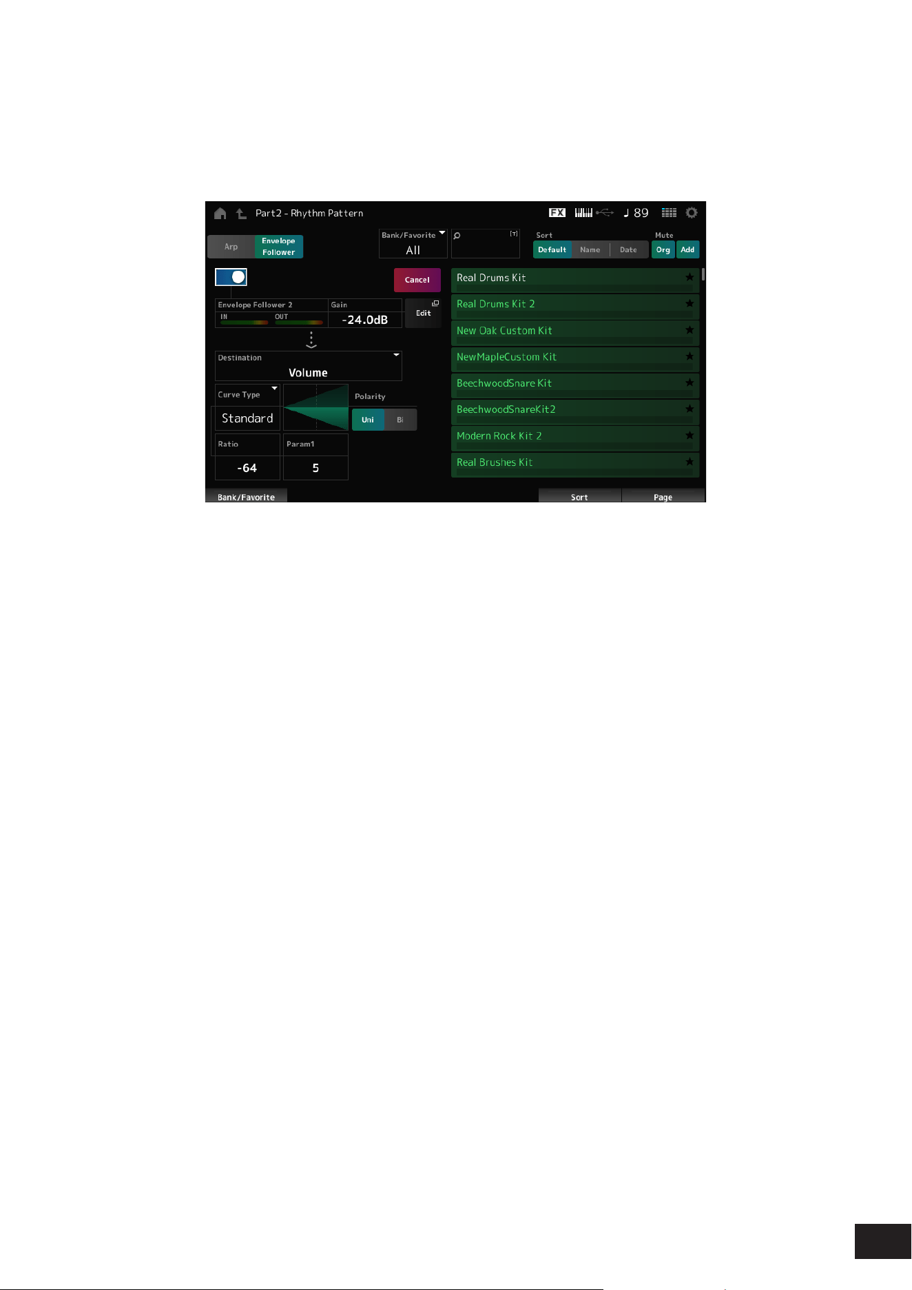
349
MODX M Operation Manual
When Envelope Follower is set to On
Frequently used parameters for the Envelope Follower settings are shown on the left side of the screen.
This allows for quick editing of parameters frequently used for Rhythm Patterns.
When you wish to change other parameters, use Edit to open the Envelope Follower Edit screen.
Quick Assign
Enables Envelope Follower.
Settings: Off, On
Gain (Envelop Follower Gain)
Sets the input gain for the input source.
Settings: −24.0dB – 0.0dB – 24.0dB
Destination
Sets the destination for the Envelope Follower.
Settings: Volume, Cutoff, Resonance, Pitch, Pan, Reverb Send, Variation Send, LFO Speed, LFO Depth 1, LFO Depth 2, LFO Depth 3
Curve Type
Polarity (Curve Polarity)
Ratio (Curve Ratio)
Param1 (Curve Parameter 1)
Param2 (Curve Parameter 2)
The same as the Control Assign screen.
Edit
The Envelope Follower Edit screen appears.
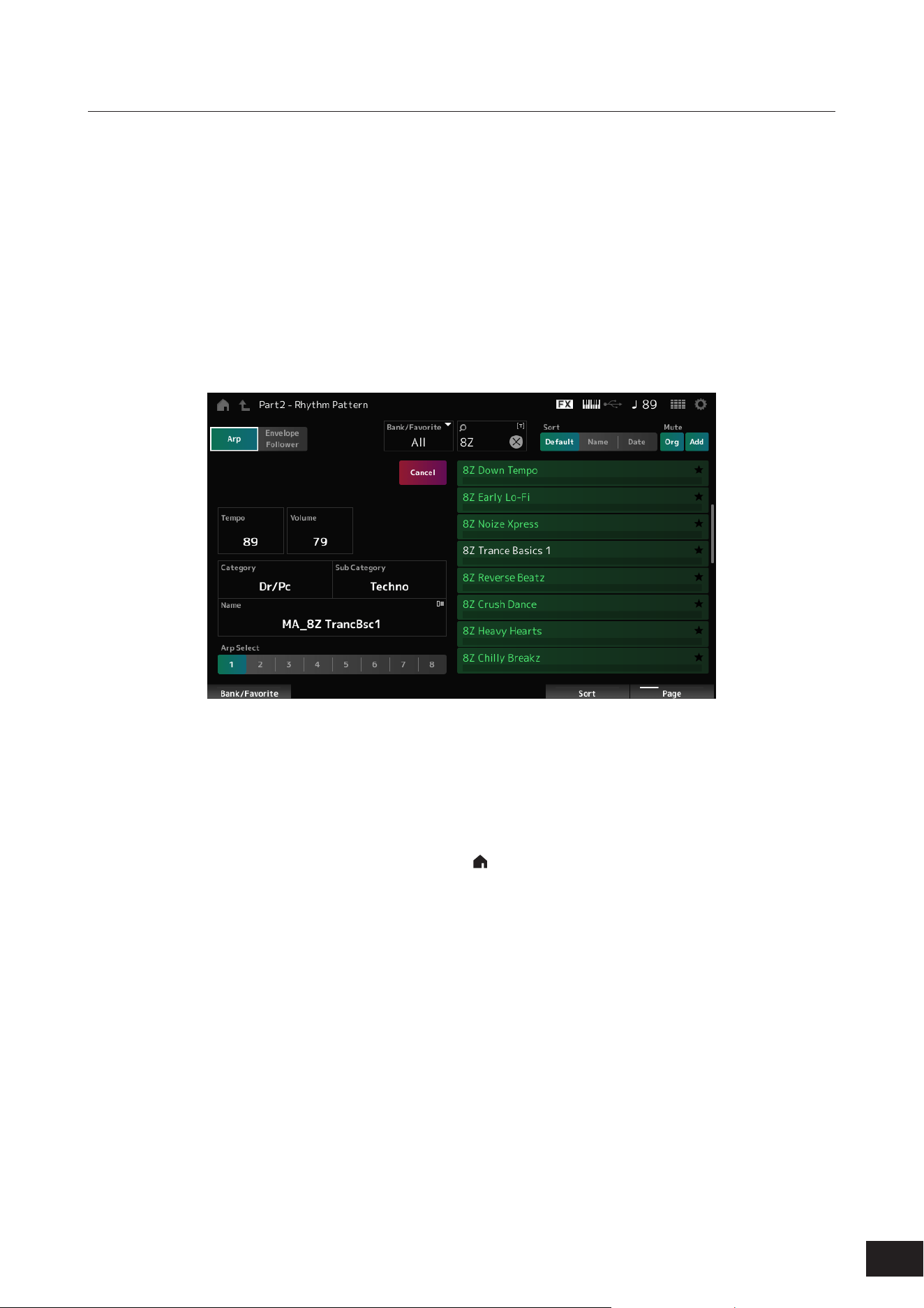
350
MODX M Operation Manual
How to use the Rhythm Pattern function
Here, we will show an example of how to add the Rhythm Pattern 8Z Trance Basics 1 to the Performance Supertrance,
and then modify the sound with the Envelope Follower.
First, add a rhythm part.
1.
Select the performance to which you want to add a rhythm part.
Select Supertrance.
2.
Press [SHIFT]+[SONG/PATTERN] to open the Rhythm Pattern screen.
When all of Parts 1–8 are being used, PartFull will be shown and no Rhythm Patterns can be added.
3.
Tap the kit of the rhythm pattern you want to use from the rhythm pattern list.
Tap 8Z Trance Basics 1.
The rhythm Part has been added.
4.
Press the key to play the rhythm.
5.
Press the [PERFORMANCE (HOME)] button or the [EXIT] button to confirm the Rhythm Pattern.
The Rhythm Pattern screen will close.
NOTE
You can also conrm the selection by tapping the HOME icon ( ).
6.
To stop the Rhythm Pattern, press the [ARP] button or the [
] (Stop) button.
Next, set the Envelope Follower. For information about the Envelope Follower, see "Using the Envelope Follower."
7.
Press [SHIFT]+[SONG/PATTERN] to open the Rhythm Pattern screen, and tap Envelope Follower.
8.
Set Quick Assign to On.
You can play the keyboard to hear the sound with the Envelope Follower enabled.
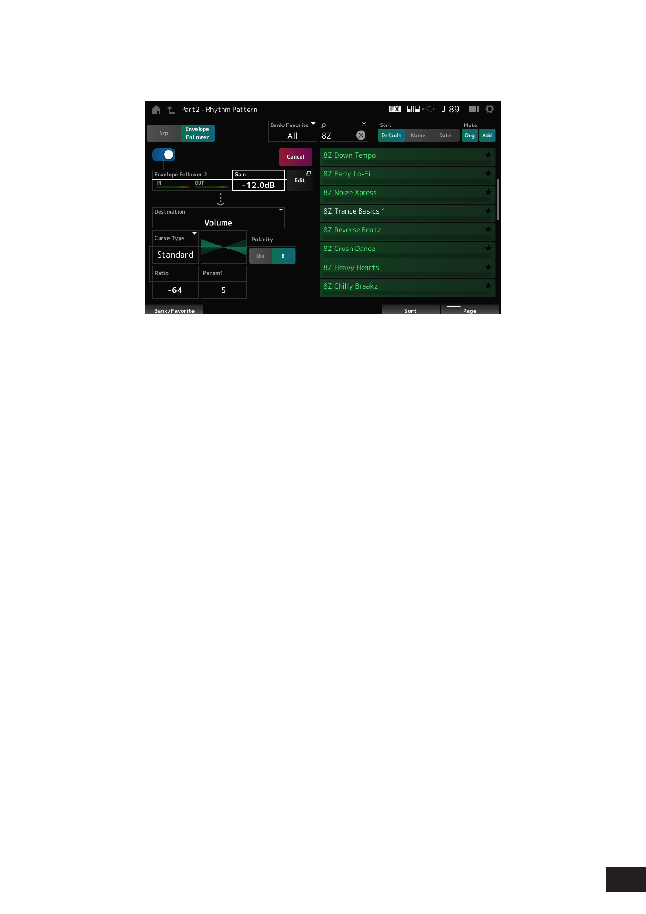
351
MODX M Operation Manual
9.
The settings can be adjusted as necessary.
Here, in this example, set the Polarity to Bi, the Ratio to −64, and the Gain to −12.0 dB.
For ner adjustments, open the Envelope Follower Edit from Edit on the screen.
When you wish to change the Rhythm Pattern kit or Arpeggio type, press [SHIFT]+[SONG/PATTERN] to go back to
the Rhythm Pattern screen. The Envelope Follower settings are retained even after the kit or the Arpeggio type has
been changed.
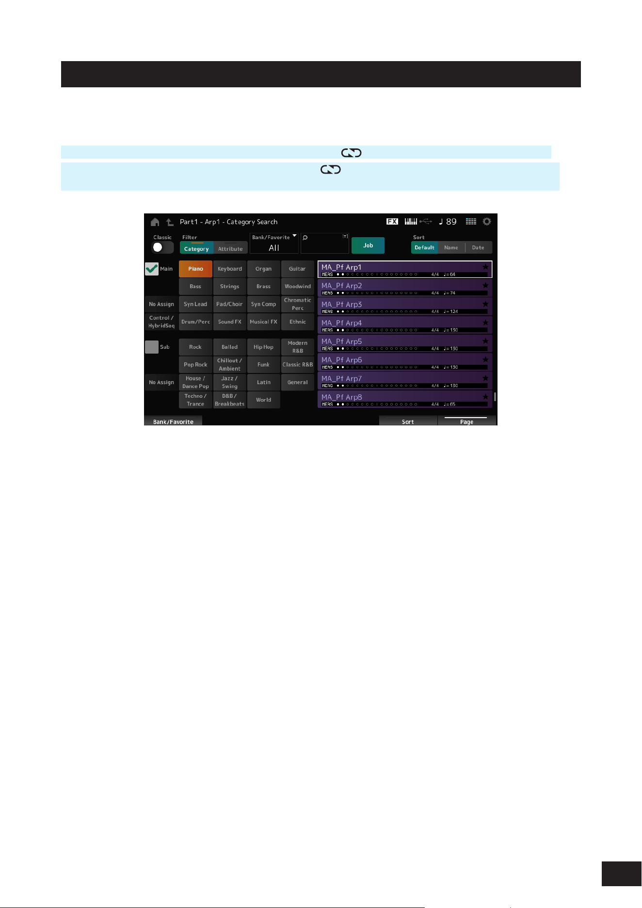
352
MODX M Operation Manual
Arp Category Search (Arpeggio Category Search)
On the Arp Category Search screen, you can search for and select Arpeggio types.
Operation
[PERFORMANCE (HOME)]
→
Part Common selection
→
[EDIT/ ]
→
Arpeggio
→
Individual
→
[CATEGORY]
[PERFORMANCE (HOME)]
→
Common selection
→
[EDIT/
]
→
Arp / MS
→
Arp Overview
→
Part selection
→
[CATEGORY]
Classic (Classic Switch)
Sets the Classic view on or off.
In the Classic view, only common arpeggios are listed, and no lters are available for search.
Settings: Off, On
Main (Main Category)
Sub (Sub Category)
Filters by category.
By unchecking the Main or Sub checkbox, you can cancel ltering by category.
Settings: Refer to the Data List
Attribute
Filters by attribute.
By unchecking the Attribute checkbox, you can cancel ltering by attribute.
Settings: Note, Chord, Other, Intro, Main, Fill, Ending, AF, Accent, Random SFX, Mg, number of bars, time signature, tempo
Bank/Favorite (Bank/Favorite Select)
Filters by bank or Favorites.
When Favorite is selected, only the Arpeggio types with Favorite Flags will appear in the list.
Settings: All, Favorite, Preset, User, Library name (when a Library le is loaded)

353
MODX M Operation Manual
Name Search
Allows you to enter certain characters included in the name for easy searching. You can use up to 20 alphanumeric
characters.
Job
Calls up the Job menu.
• Delete
Deletes the selected content.
This parameter is available only when the Arpeggio in the User Bank is selected.
• Rename
Changes the name of the selected content.
This parameter is available only when the Arpeggio in the User Bank is selected.
• Favorite All Clear
Clears all Favorite Flags from the Arpeggios.
This parameter is not available when there are no Arpeggio types with Favorite Flags.
Sort
Sets the sort order of the Arpeggio type list.
Settings: Default, Name, Date
Name: Sorts by name. The down arrow indicates that the list is arranged in ascending order (A to Z). The up arrow indicates
that the list is arranged in descending order.
Date: Sorts by date the setting was loaded. The down arrow indicates that the list is arranged in descending order (new to
old). The up arrow indicates that the list is arranged in ascending order.
Arpeggio list
Shows the Arpeggio name, number of measures, time signature, recommended tempo, Attributes, and Favorite Flag
status.
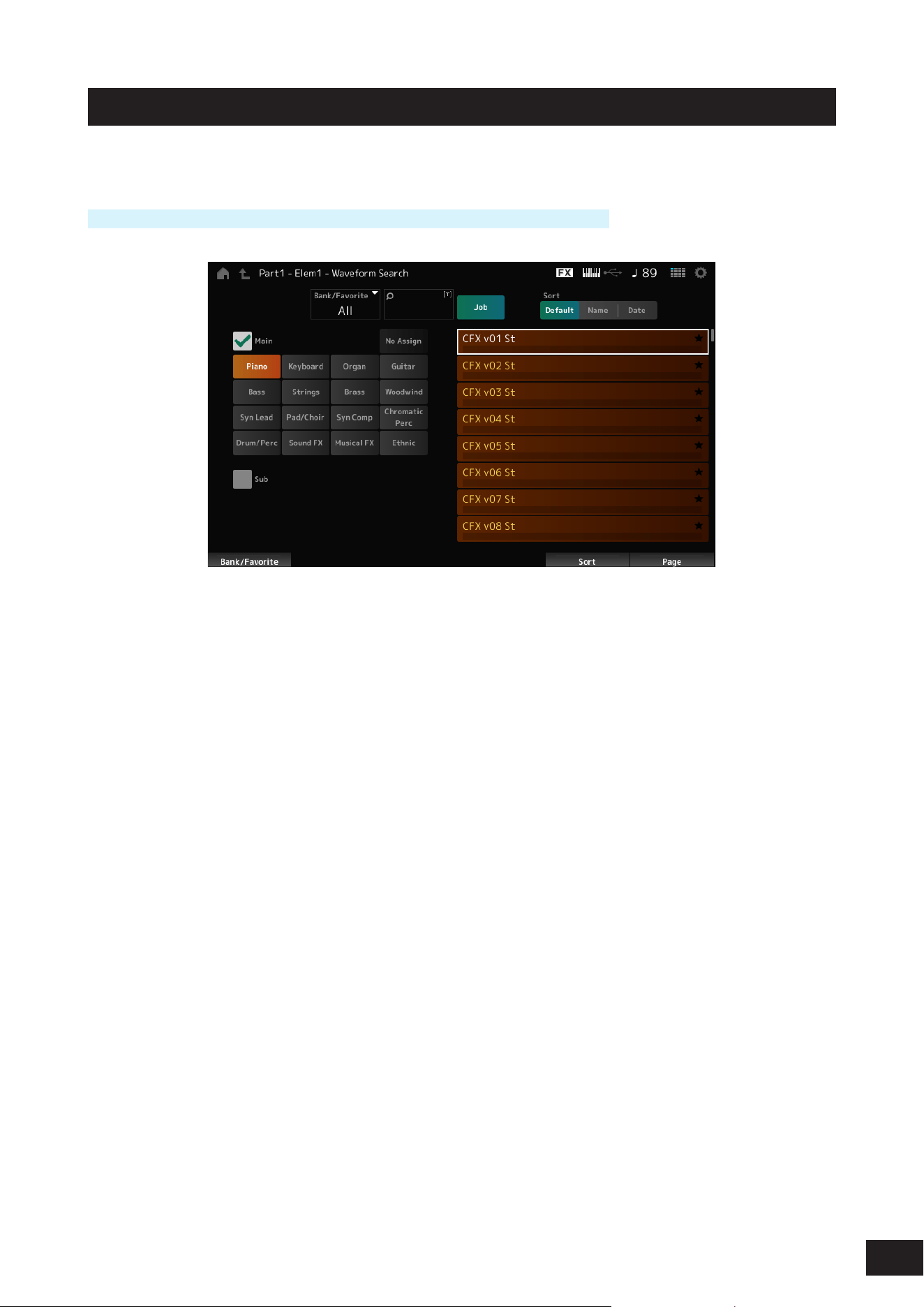
354
MODX M Operation Manual
Waveform Search (Waveform Category Search)
On the Waveform Search screen, you can search for and select Waveforms.
Operation
Waveform-related screen
→
Part selection
→
Waveform selection
→
[CATEGORY]
Bank/Favorite (Bank/Favorite Select)
Filters by bank or Favorites.
When Favorite is selected, only Waveforms with Favorite Flags will appear in the list.
Settings: All, Favorite, Preset, User, Library name (when a Library le is loaded)
Name Search
Allows you to enter certain characters included in the name for easy searching. You can use up to 20 alphanumeric
characters.
Main (Main Category)
Sub (Sub Category)
Filters by category. By unchecking the Main or Sub checkbox, you can cancel ltering by category.
Settings: Refer to the Data List
Job
Calls up the Job menu.
• Delete
Deletes the selected content.
This parameter is available only when a Waveform in the User Bank is selected.
• Rename
Changes the name of the selected content.
This parameter is available only when a Waveform in the User Bank is selected.
• Favorite All Clear
Clears all Favorite Flags from the Waveforms.
This parameter is not available when there are no Waveforms with Favorite Flags.

355
MODX M Operation Manual
Sort
Sets the sort order of the Waveform list.
Settings: Default, Name, Date
Name: Sorts by name. The down arrow indicates that the list is arranged in ascending order (A to Z). The up arrow indicates
that the list is arranged in descending order.
Date: Sorts by date the setting was stored. The down arrow indicates that the list is arranged in descending order (new to old).
The up arrow indicates that the list is arranged in ascending order.
Waveform list
Shows the Waveform list.
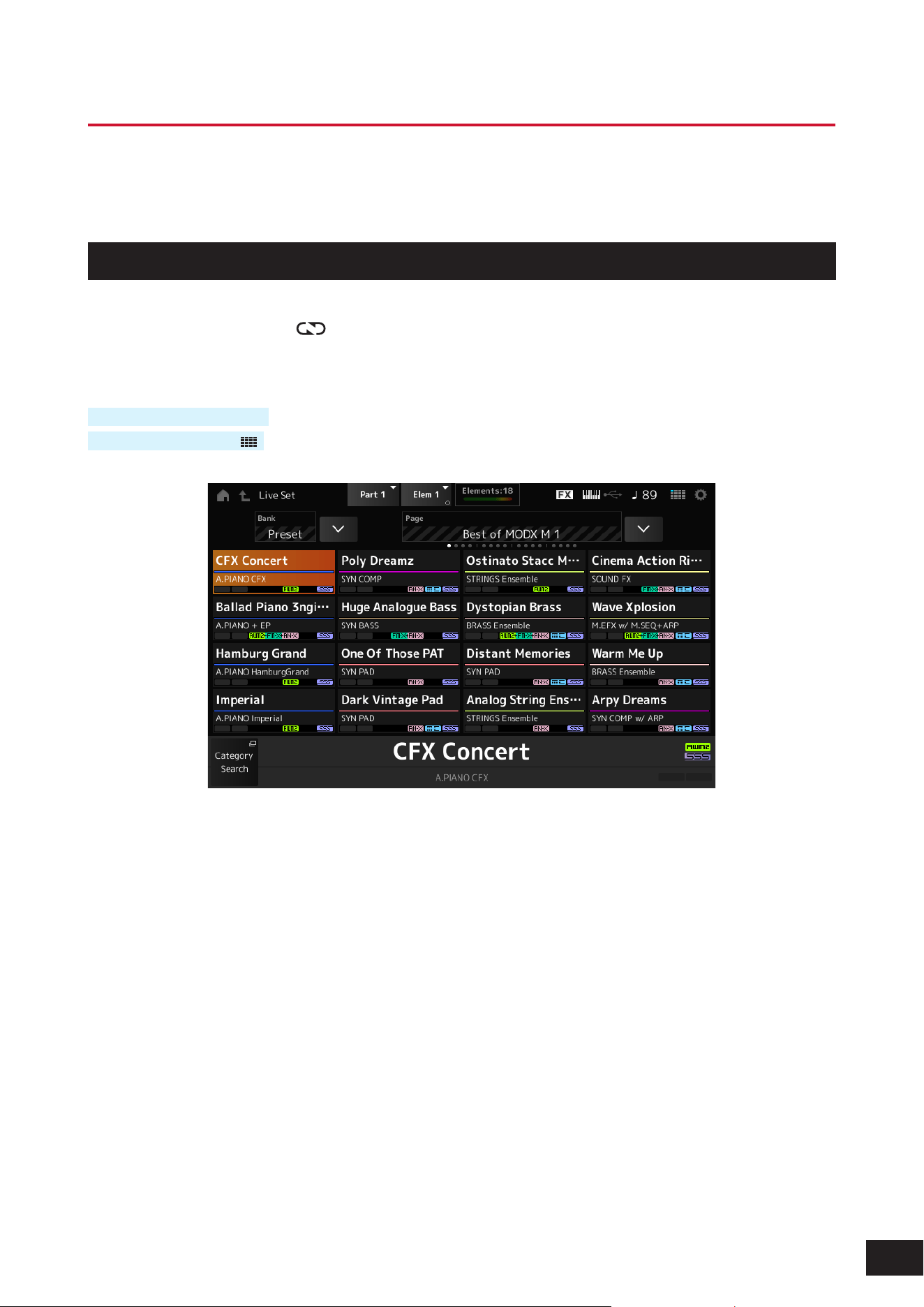
356
MODX M Operation Manual
Live Set Screens
The Live Set function is a convenient way to instantaneously change among different Performances as you play songs on
a setlist, for example.
Live Set
On the Live Set screen, you can call up a Performance.
When you press [SHIFT] + [EDIT/
] while the User Bank is selected, a dialog will be shown and then you can copy or
exchange pages or banks.
Operation
Press the [LIVE SET] button
Tap the LIVE SET icon (
)
Bank (Bank Name)
Selects the Live Set bank.
Settings: Preset, User 1–8 (factory default settings), Library name (when a Library le is loaded)
Page
Selects the Live Set page.
Edit
The Live Set Edit screen appears.
Edit appears only when User Bank is selected.
Live Set Slot 1–16
Displays a list of Performances registered on the selected Live Set page.
Category Search
The Performance Category Search screen will open.

357
MODX M Operation Manual
Current Performance Name
Shows the name of the Performance registered in the selected slot.
Current Slot Name
Shows the name of the selected slot.
When a Pattern, Song, or audio is assigned to a slot, the name of the Pattern or Song, or the audio le will be shown.
Performance Attribute
Shows the attribute(s) of the Performance registered in the selected slot.
On the Live Set screen, the PTN icon changes to PTN CHAIN when a Pattern with chain on is assigned to a slot.
PTN: Displayed for a slot to which a Pattern is assigned.
PTN CHAIN: Displayed for a slot to which a Pattern with chain on is assigned.
SONG: Displayed for a slot to which a Song is assigned.
AUDIO: Displayed for a slot to which audio is assigned.
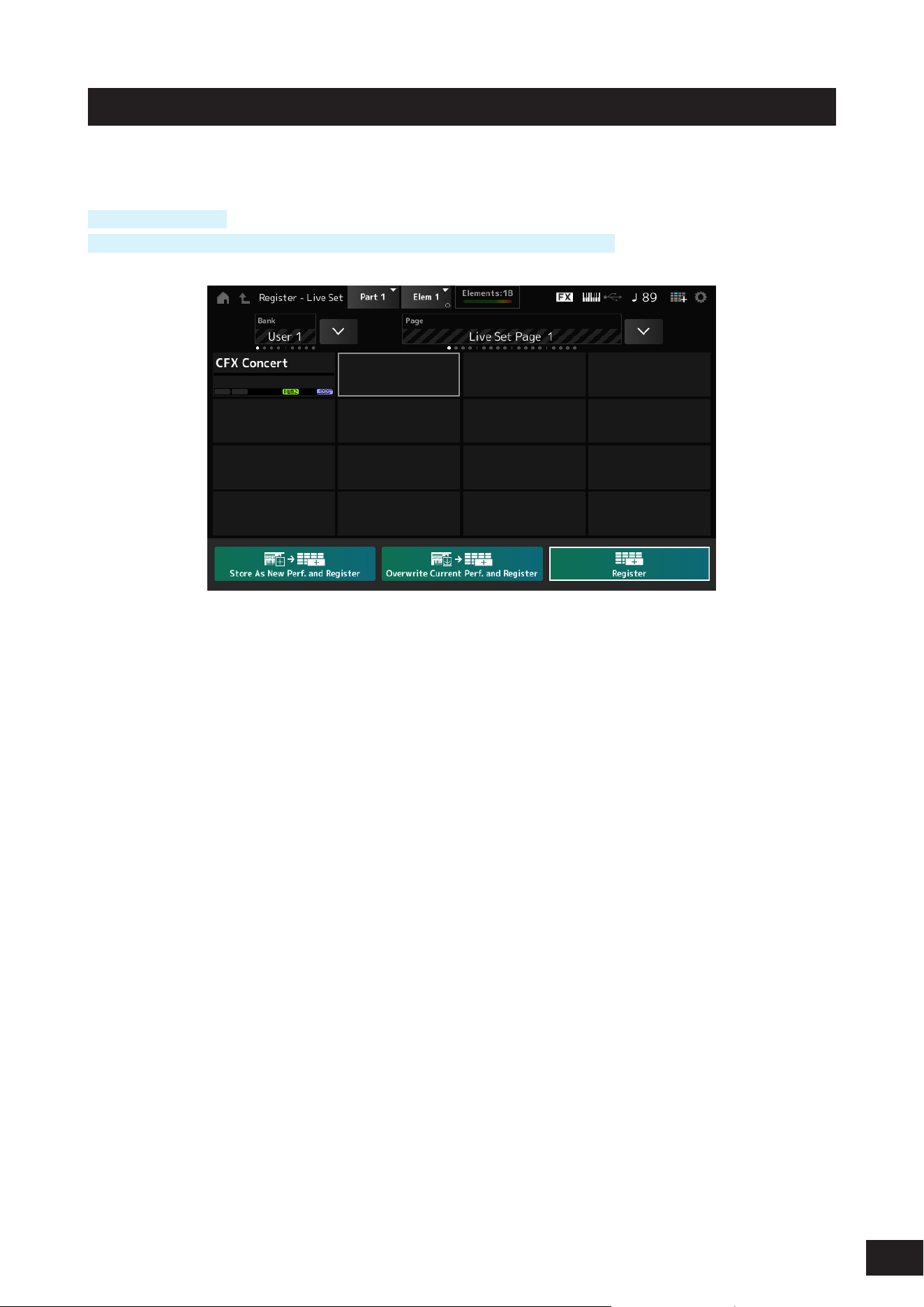
358
MODX M Operation Manual
Live Set Register
On the Live Set Register screen, you can register Performances to Live Set slots.
Operation
[SHIFT] + [LIVE SET]
While holding down the [SHIFT] button, tap the LIVE SETicon on the Navigation bar
Store as New Perf. and Register (Store as New Performance and Register)
Stores the current Performance as a new Performance and registers it to the selected slot.
Jump to Data Utility
The Data Utility screen appears.
Overwrite Current Perf. and Register (Overwrite Current Performance and Register)
Stores the new Performance over the existing Performance and registers it to the selected slot.
Register
Registers Performances.
While holding down the [SHIFT] button, press Register to register a Performance by inserting it between slots.
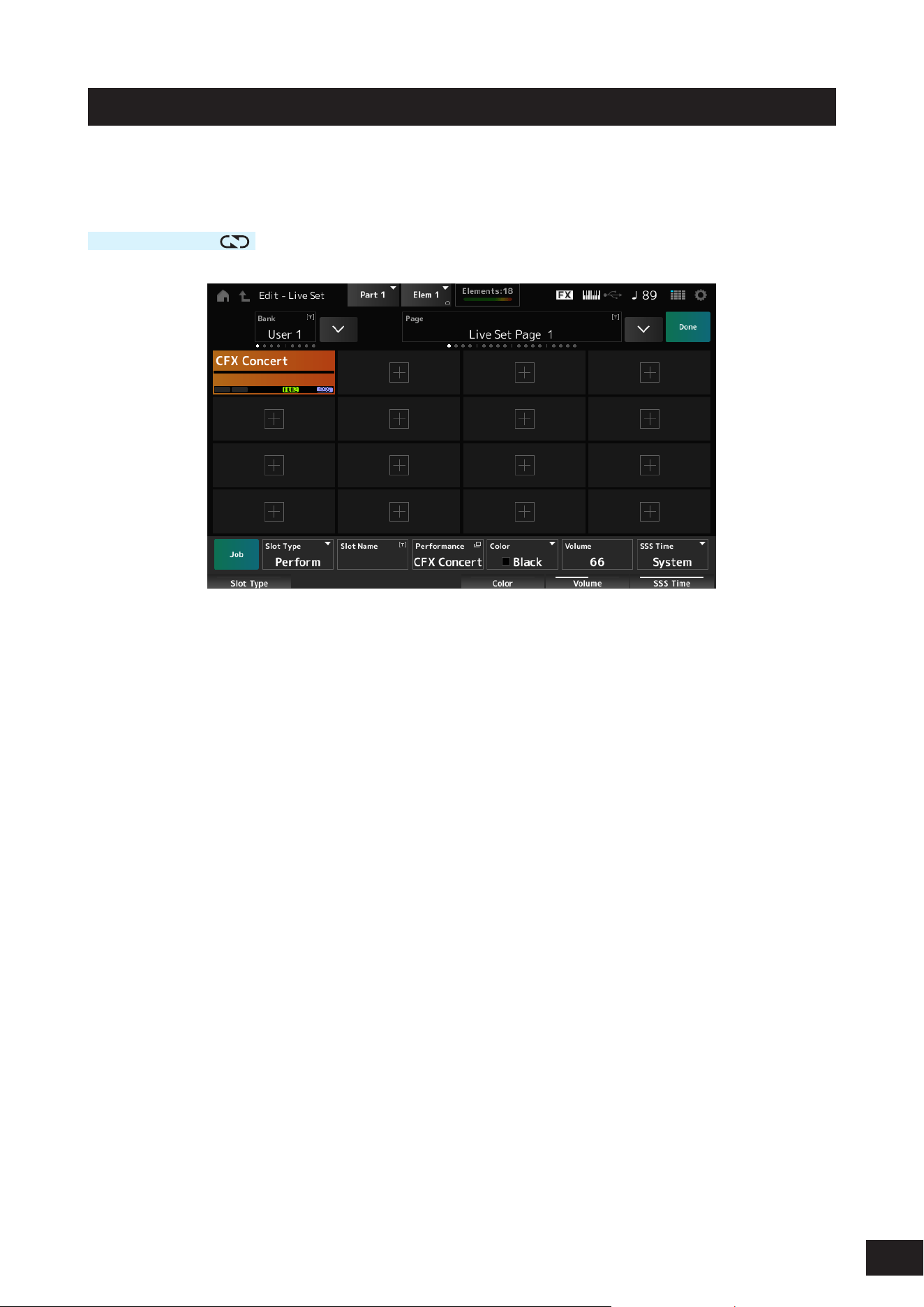
359
MODX M Operation Manual
Live Set Edit
On the Live Set Edit screen, you can edit Live Sets.
Only Live Sets in the User Bank can be edited.
Operation
[LIVE SET]
→
[EDIT/
]
Bank (Bank Name)
Saves the selected Live Set bank under a new name. You can use up to 20 alphanumeric characters.
Page (Page Name)
Saves the selected Live Set page under a new name. You can use up to 20 alphanumeric characters.
Done
Tap to close the Live Set Edit and show the Live Set screen.
Live Set Slot 1–16
Displays a list of Performances registered to the selected Live Set.
[+] (Add)
Tap to register the selected Performance to that slot.
Job
Calls up the Job menu.
• Copy
Turns the copy function on.
You can copy settings by selecting a slot to copy from, tapping Copy, and then selecting the slot to copy to.
Settings: Off, On
• Exchange
Turns the exchange function on.
You can exchange settings by selecting the rst slot, tapping Exchange, and then selecting the second slot.
Settings: Off, On
• Delete
Select the slot, and then tap Delete to delete any registered Performances and other settings from the slot.
• Delete & Move
Select the slot, and then tap Delete & Move to delete any registered Performances and other settings from the slot
and move the subsequent slots up.

360
MODX M Operation Manual
Slot Type
Selects the slot type.
Settings: Perform, Song, Audio, Pattern
Perform: Registers only the Performance to the slot
Song: Registers the Performance and Song to the slot
Audio: Registers the Performance and audio le to the slot
Pattern: Registers the Performance and Pattern to the slot
Slot Name
Song Name
Audio Name
Pattern Name
Shows the Slot Name when the Slot Type is Perform.
Tapping on the name calls up the onscreen keyboard, allowing you to enter a name for the current slot. You can use up
to 20 alphanumeric characters.
When the Slot Type is Pattern, the Pattern Name is displayed; when it is Song, the Song Name is displayed; and when it
is Audio, the Audio Name is displayed. The registered Pattern, Song or Audio will be shown. When you tap on the name,
the Utility Load screen appears. Then you can select the Pattern, Song, or Audio to register.
Performance (Performance Name)
Shows the name of the Performance registered to the selected slot.
Tap to display the Performance Category Search screen.
Color
Sets the color for the selected slot.
Settings: Black, Red, Yellow, Green, Blue, Azure, Pink, Orange, Purple, Sakura, Cream, Lime, Aqua, Beige, Mint, Lilac
Volume
Sets the volume of the Performance registered in the selected slot.
SSS Time
Adjusts the SSS Time of the selected slot. If you set the SSS Time, even if you change the Performance while playing, if
the sound being played is set to Note Off, the sound will fade out after the set time.
Settings: 0.0sec – 30sec, Hold, System
Playing back the Pattern, Song, or Audio file from the Live Set screen
Operation
[LIVE SET] (or tap the LIVE SET icon on the top panel)
→
User Bank selection
→
Slot selection
→
[
] (Play) button
NOTE
• Performance and slot cannot be changed while the Pattern or Song is being played back. If you attempt to change them, an error
message will appear.
• When you press the [
] (Play) button while the Pattern, Song, or Audio le is played back, the Pattern, Song, or Audio le playback
screen will open.
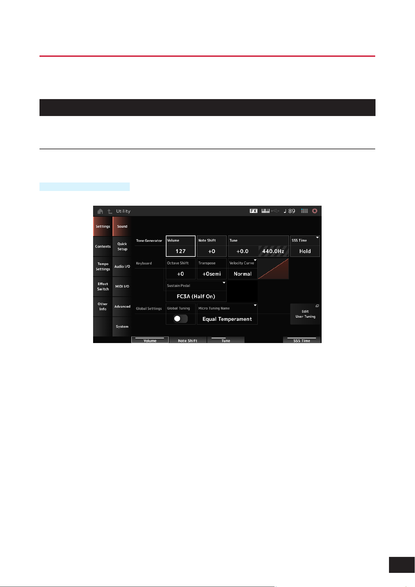
361
MODX M Operation Manual
Utility Screens
The Utility screen is used for setting common items for the entire instrument.
Settings
Sound
The Sound screen is used for setting the sound output from the instrument.
Operation
[UTILITY]
→
Settings
→
Sound
Tone Generator Volume
Sets the overall volume of the sound output from the instrument.
Settings: 0–127
Tone Generator Note Shift
Adjusts the pitch of the overall sound produced by the Tone Generator block of the instrument in semitones.
Settings: −24–+0–+24
Tone Generator Tune
Adjusts the tuning of the overall sound produced by the Tone Generator block of the instrument in semitones. You can
ne-adjust the pitch in units of cents.
Settings: −102.4–+0.0–+102.3
SSS Time
Adjusts the SSS Time of the overall sound produced by the Tone Generator block of the instrument. When selected, the
Live Set Slot's SSS Time will be applied.
Settings: 0.0sec – 30sec, Hold, System

362
MODX M Operation Manual
Keyboard Octave Shift
Shifts the pitch of the keyboard in octaves. It is linked to the [OCTAVE] buttons on the top panel.
Settings: −3–+0–+3
NOTE
The Keyboard Octave Shift setting will be set to 0 the next time you start the program.
Keyboard Transpose
Shifts the pitch of the keyboard in semitones.
Settings: −11semi to +0semi to +11semi
NOTE
• If the pitch exceeds the range (C -2 to G8) that the sound source section of the unit can play, a note one octave higher (or lower) will
be output.
• The Keyboard Transpose setting will be set to +0semi the next time you start the program.
Keyboard Velocity Curve
Sets the velocity curve to determine how velocity is expressed in relation to the strength with which the keys are played.
The horizontal axis of the graph displayed on the screen of the instrument indicates the strength with which the keys are
played, and the vertical axis indicates the velocity output from the keys.
Settings: Normal, Soft 1, Soft 2, Hard 1, Hard 2, Wide, Fixed
Normal: The most common curve, where the strength and velocity of the keystroke are proportional
Soft 1: Provides increased response
Soft 2: The curve between Soft 1 and Normal
Hard 1: Provides decreased response
Hard 2: The curve between Hard 1 and Normal
Wide: A curve that suppresses velocity with a light touch and makes velocity more pronounced with a strong touch. It
provides a feeling of a wider dynamic range.
Fixed: Used when you want to create a sound source with a constant velocity regardless of the strength of the key presses.
The value set in Keyboard Fixed Velocity is used as the velocity value
Keyboard Fixed Velocity
Sends a xed velocity to the tone generator regardless of how hard or soft you play the keyboard.
This is only valid if you set the Keyboard Velocity Curve parameter to Fixed.
Settings: 1–127
Sustain Pedal (Sustain Pedal Select)
Select the type of footswitch connected to the FOOT SWITCH [SUSTAIN] jack on the rear panel.
• FC3, FC3A (half-damper feature enabled)
Select FC3A (Half On). If you do not need to use the half-damper feature, select FC3A (Half Off).
• FC4, FC4A, FC5
Select FC4A or FC5. The half-damper feature is not available with the FC4, FC4A, and FC5.
• Pedal with reverse polarity
Select Reverse Polarity. The half-damper feature is not available.
Settings: FC3A (Half On), FC3A (Half Off), FC4A/FC5, Reverse Polarity
NOTE
If you are using control changes from an external MIDI device to play half damper, the Sustain Pedal (Sustain Pedal Select) setting is
not necessary.

363
MODX M Operation Manual
Global Tuning (Global Micro Tuning Switch)
When this parameter is On, the micro tuning settings in the global settings are prioritized over the micro tuning settings
for each Part of the Performance. This applies to all Parts except the Drum Part.
Settings: Off, On
NOTE
The Global Tuning (Global Micro Tuning Switch) setting will be set to Off the next time you start the program.
Micro Tuning Name (Global Micro Tuning Name)
Shows the name of the selected micro tuning. Tapping on the name lets you call up the menu for selecting the micro
tuning.
Settings: Preset: Equal Temperament, Pure Major, Pure Minor, Werckmeister, Kirnberger, Vallotti & Young, 1/4 shift, 1/4 tone, 1/8 tone,
Indian, Arabic1, Arabic2, Arabic3
User: Init Tuning1–8
Library: Library name (when a Library le is loaded)
Root (Global Micro Tuning Root)
Sets the root note for the micro tuning. This parameter is not shown if the selected type in Micro Tuning Name does not
require a root note.
Settings: C–B
Edit User Tuning
Opens the User Micro Tuning settings window.
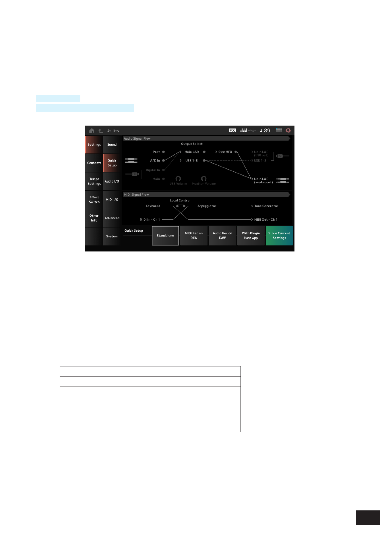
364
MODX M Operation Manual
Quick Setup
This function allows you to set all necessary settings for connecting the external device to the optimal values by simply
selecting a group of settings.
Parameters across several setting screens can be set all at once to suit the intended purpose.
Operation
[QUICK SETUP]
[UTILITY]
→
Settings
→
Quick Setup
Audio Signal Flow
Displays the current audio signal ow diagram.
The signal ow depicted changes depending on the connection on the USB [TO HOST] terminal and the other settings of
the instrument.
MIDI Signal Flow
Displays the current MIDI signal ow diagram.
The signal ow diagram changes depending on the settings of the instrument.
Quick Setup (Quick Setup Select)
Selects Quick Setup.
Settings: Standalone, MIDI Rec on DAW (Setup No.1), Audio Rec on DAW (Setup No.1), With Plugin Host App (Setup No.3)
The parameters stored in each quick setup are as follows:
Audio settings
Direct Monitor
MIDI settings
Local Control
Performance settings
Part 1–16 Output Select
A/D In Output Select
Digital In Output Select
Part 1–8 Keyboard Control Switch
Part 1–16 Part Mode
Part 1–16 Transmit Channel
See Audio I/O for audio setting parameters and MIDI I/O for MIDI setting parameters.

365
MODX M Operation Manual
Quick Setup initial settings
• Standalone
Settings for using the instrument by itself and for operating the external device from the instrument
Direct Monitor Local Control Output Select Keyboard Sw Part Mode Transmit Ch
On On Main L&R Part 1–8: On Part 1–16: Int Part 1–16: Ch 1–16
• MIDI Rec on DAW
Settings for recording your performance in MIDI on DAW software
Direct Monitor Local Control Output Select Keyboard Sw Part Mode Transmit Ch
On Off Main L&R Part 1–8: On Part 1–16: Int Part 1–16: Ch 1–16
• Audio Rec on DAW
Settings for recording each Part on the internal Tone Generator to DAW software as an individual audio track
Direct Monitor Local Control Output Select Keyboard Sw Part Mode Transmit Ch
Off On Different for each
Part
Part 1–8: On Part 1–16: Int Part 1–16: Ch 1–16
• With Plugin Host App
Settings for using the internal Tone Generator with a sound generator plug-in on a computer
Direct Monitor Local Control Output Select Keyboard Sw Part Mode Transmit Ch
On On Main L&R Part 1–5: On
Part 6–8: Off
Part 1–4: Int
Part 5–16: Ext
Part 1–4: Ch 1–4
Part 5–8: Ch 1–4
Part 9–16: Ch 9–16
Store Current Settings
You can save the current settings to any one of Setup No.1–3 of Quick Setup.
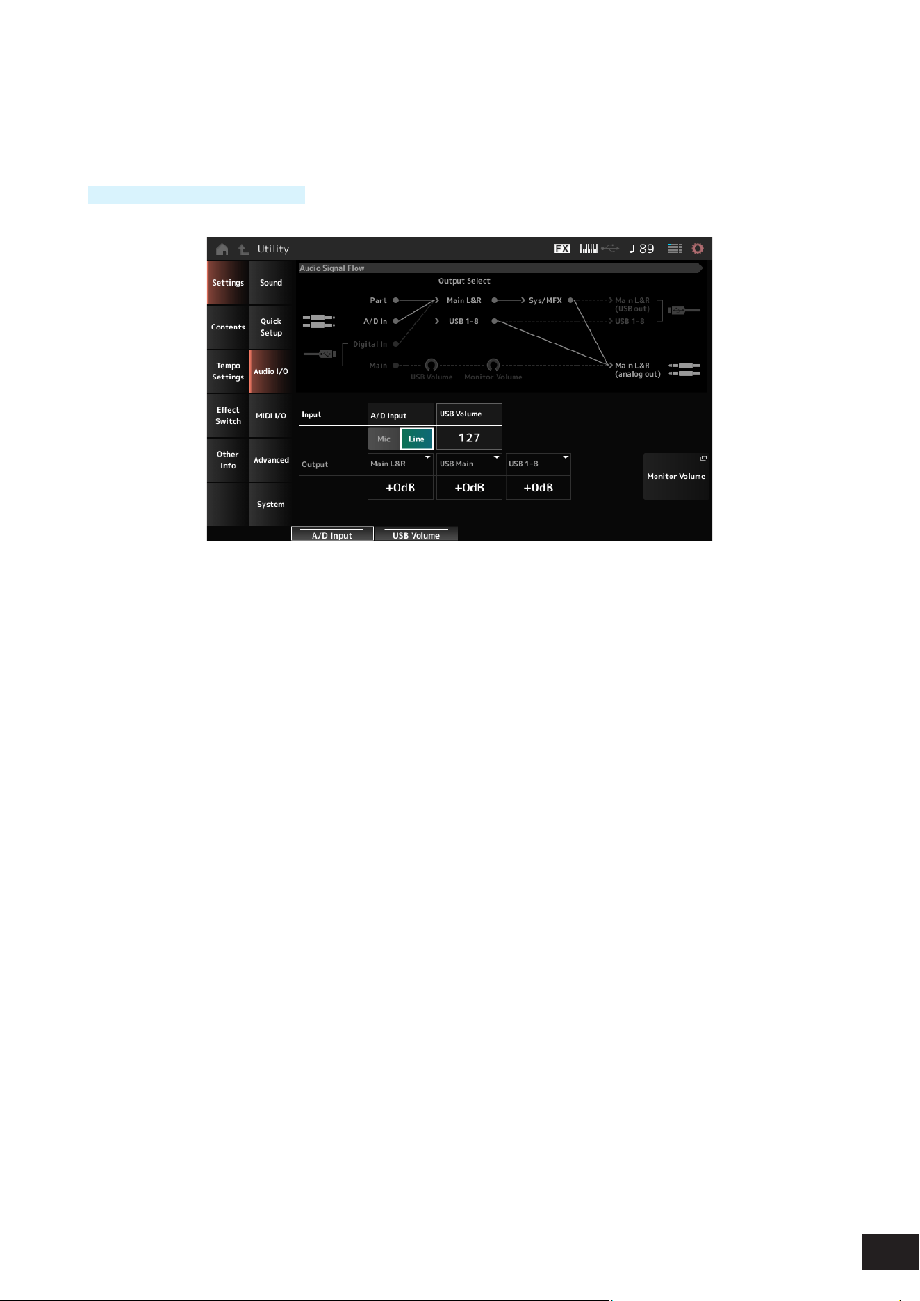
366
MODX M Operation Manual
Audio I/O
On the Audio I/O screen, you can set the audio signal input and output.
Operation
[UTILITY]
→
Settings
→
Audio I/O
Audio Signal Flow
Displays the current audio signal ow diagram.
The signal ow depicted changes depending on the connection on the USB [TO HOST] terminal and the other settings of
the instrument.
A/D Input (A/D Input Gain)
Sets the input gain for the A/D INPUT jack to Mic or Line.
Settings: Mic, Line
Mic: Intended for a device with a low output level, such as a microphone.
Line: Intended for a device with a high output level, such as a synthesizer, or audio device.
NOTE
A guitar or bass having an active pickup can be directly connected. On the other hand, when using a passive pickup, connect the
instrument via an effect unit or direct box.
USB Volume (USB Input Volume)
Adjusts the volume of the audio signal input from the USB [TO HOST] terminal.
Settings: 0–127
NOTE
The USB input volume is stored as a system-wide setting and not on a per-performance basis.
Direct Monitor
Sets the audio signal output from Main L&R, USB Main or USB 1–8 channels to the external device (such as a computer)
to be also played back from this instrument (direct monitoring).
When this is set to On, the audio signals output to the Main L&R, USB Main, and USB 1–8 channels are also sent to the
OUTPUT [L/MONO] and [R] jacks and the [PHONES] jack of the instrument. When there is no USB connection, this is
automatically turned On.
Settings: Off, On

367
MODX M Operation Manual
Main L&R (Analog Output L&R Output Gain)
Sets the output gain of the OUTPUT [L/MONO] and [R] terminals.
Settings: −6dB, +0dB, +6dB, +12dB
USB Main (USB Main L&R Output Gain)
Sets the output gain of the Main L&R channel of the USB [TO HOST] terminal.
Settings: −6dB, +0dB, +6dB, +12dB
USB 1-8 (USB Individual Output Gain)
Sets the output gain of the channels 1–8 of the USB [TO HOST] terminal.
Settings: −6dB, +0dB, +6dB, +12dB
Monitor Volume
The Monitor Volume screen appears.
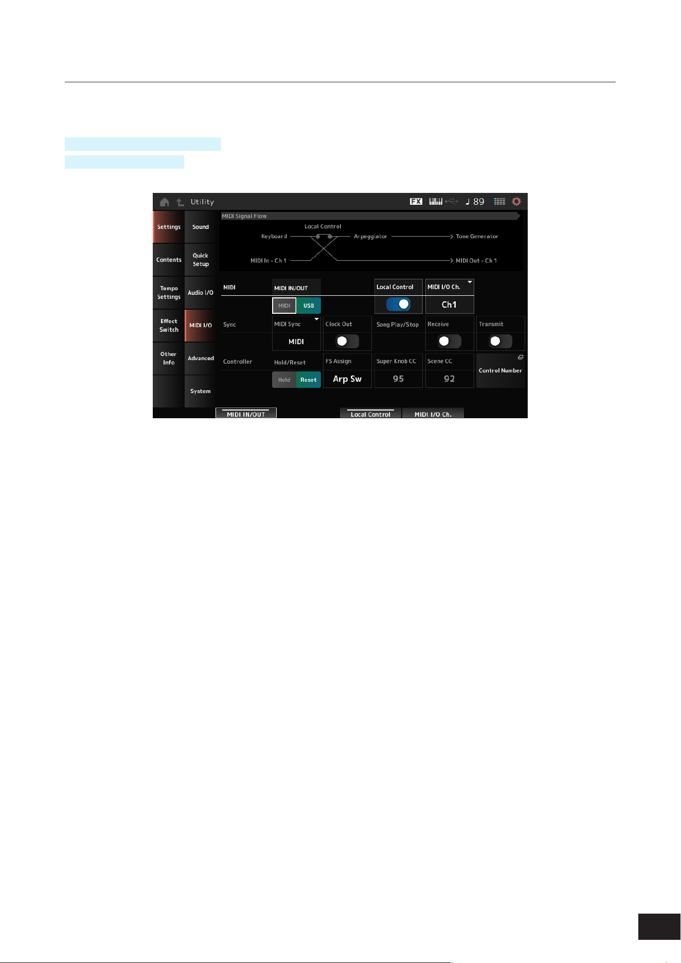
368
MODX M Operation Manual
MIDI I/O
The MIDI input and output is set on the MIDI I/O screen.
Operation
[UTILITY]
→
Settings
→
MIDI I/O
Tap the Quick Setup icon
MIDI Signal Flow
Displays the current MIDI signal ow diagram. The ow diagram changes depending on the settings of the instrument.
By tapping near the Local Control switch on the MIDI Signal Flow, you can turn Local Control On or Off.
MIDI IN/OUT
Selects the terminal(s) for transmitting and receiving MIDI messages.
Settings: MIDI, USB
MIDI Thru
Species whether the MIDI [OUT] terminal is used as a MIDI Thru terminal.
Settings: Off, On
Local Control
Switches Local Control on or off.
When the Local Control is set to Off, the instrument's Controller block and the Tone Generator block will be disconnected,
and no sound is produced when you play the keyboard.
However, regardless of this setting, the keyboard performance data on this instrument are transmitted as MIDI messages.
In addition, MIDI input messages are processed by the Tone Generator block.
Settings: Off, On
MIDI I/O Channel
Sets the MIDI channel for input and output of the Common and the Part with the Keyboard Control Switch to be set to On.
Settings: Ch1–Ch16
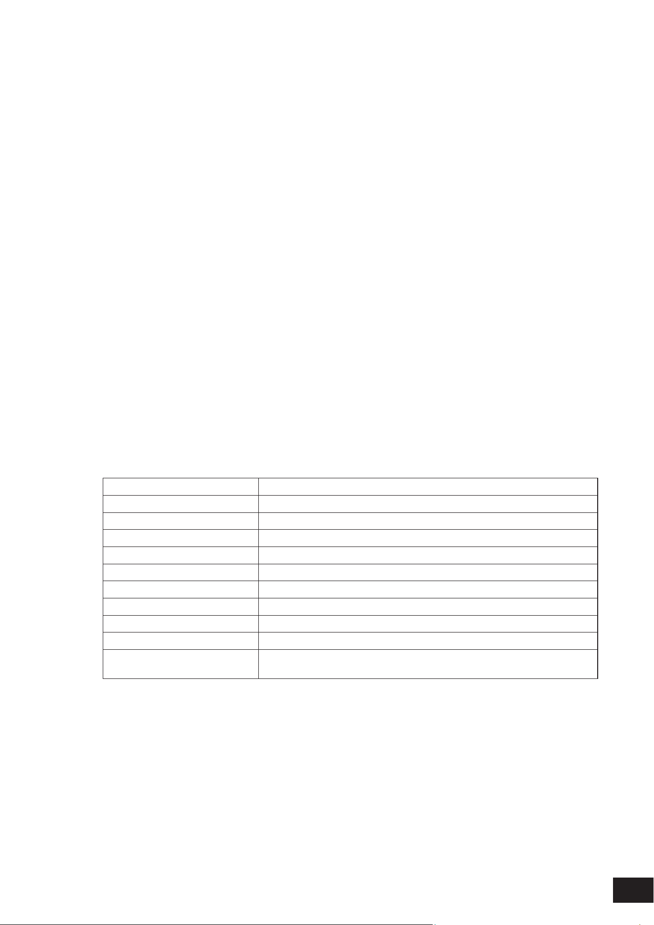
369
MODX M Operation Manual
MIDI Sync
Sets the parameters related to synchronization to the connected external device.
Select the internal clock of this instrument or the external MIDI clock of DAW software on the computer or the external
MIDI device, or the audio signal input from the A/D INPUT jacks for playing back the Arpeggios, Motion Sequencer,
Songs, and Patterns.
Settings: Internal, MIDI, A/D In (ABS)
Internal: Synchronizes to the internal clock. For using this instrument by itself or as the master clock source for other devices
to sync to.
MIDI: Synchronizes to the MIDI clock received from the external MIDI device. For using the external device as the master
clock source.
A/D In (ABS): Operates by extracting the tempo from the audio signal input from the A/D INPUT terminal using the Audio
Beat Sync function.
Clock Out (MIDI Clock Out)
Sets the MIDI clock messages to be transmitted.
Settings: Off, On
Receive (Receive Sequencer Control)
Receives the MIDI messages for starting and stopping the Song.
Settings: Off, On
Transmit (Transmit Sequencer Control)
Transmits the MIDI messages for starting and stopping the Song.
Settings: Off, On
Controller Hold/Reset
Sets whether to use the current settings of the controllers such as modulation wheel, aftertouch, foot controller, and
breath controller (Hold) or to reset to their initial settings (Reset) when you switch between Performances.
Settings: Hold, Reset
When set to Reset, the controllers will be reset when you switch between Performances as shown below:
Pitch bend Center
Modulation wheel Minimum
Aftertouch Minimum
Foot controller Maximum
Footswitch Off
Ribbon controller Center
Breath controller Maximum
Expression Maximum
Assignable switches 1 and 2 Off
[KEYBOARD HOLD] button Off
Each lane of the motion sequencer When the Motion Seq Polarity for the lane is set to Unipolar: the value is 0 (minimum)
When the Motion Seq Polarity for the lane is set to Bipolar: the value is 64 (center)
FS Assign (FootSwitch Assign Control Number)
Sets the Control Change number generated by the operation of the footswitch connected to the FOOT SWITCH
[ASSIGNABLE] jack. When this instrument receives a MIDI message with the same Control Change number specied
here from the external MIDI device, the instrument will act as if the footswitch has been operated.
Settings: Off, 1–95, Arp Sw, MS Sw, Play/Stop, Live Set+, Live Set−, Oct Reset, Tap Tempo

370
MODX M Operation Manual
Super Knob CC (Super Knob Control Change Number)
Sets the Control Change number generated by the operation of the Super Knob.
When this instrument receives the MIDI message with the same Control Change number specied here from the external
device, the instrument will act as if the Super Knob has been operated.
Settings: Off, 1–95
NOTE
When this parameter is set to Off, the System Exclusive (SysEx) is used for handling MIDI messages.
Scene CC (Scene Control Change Number)
Sets the Control Change number generated when you switch between Scenes.
Also, Scene will change when a MIDI message with the same Control Change number set here is received from the
external MIDI device.
Settings: Off, 1–95
NOTE
• Depending on the Control Change number, one of the Scenes 1–8 will be selected.
0–15: Scene 1, 16–31: Scene 2, 32–47: Scene 3, 48–63: Scene 4, 64–79: Scene 5, 80–95: Scene 6, 96–111: Scene 7, 112–127:
Scene 8
• If the Super Knob CC number and the Scene CC number are set to the same value, an exclamation mark appears in front of the
number. In that case, the Scene Control Change takes priority, and the Super Knob Control Change is disabled.
Control Number
Opens Control
→
Control Number on the Common Edit screen.

371
MODX M Operation Manual
Advanced
On the Advanced screen, you can set the detailed settings for the instrument.
Operation
[UTILITY]
→
Settings
→
Advanced
Audition Lock
Switches the audition lock On or Off. When set to On, the audition function is disabled.
Settings: Off, On
Audition Loop
When this is set to On, the audition phrase will be played back in a loop.
When this is set to Off, the playback of the audition phrase will stop automatically after it has been played to the end.
Settings: Off, On
Kbd Hold Lock (Keyboard Hold Lock)
Switches Keyboard hold function On or Off. When set to On, the keyboard hold function is disabled.
It works in conjunction with the [KEYBOARD HOLD] button.
Settings: Off, On
Auto Power Off (Auto Power Off Time)
Auto power off is a function that automatically turns off the power if the unit is not operated for a certain period of time in
order to prevent unnecessary power consumption due to leaving the unit on by accident.
Here, you can set the length of time until the instrument is automatically turned off.
Settings: Off (Auto Power Off disabled), 5min, 10min, 15min, 30min, 60min, 120min
Device Number
Sets the MIDI device number. For sending and receiving System Exclusive messages such as Bulk Dump and Parameter
Change to and from an external MIDI device, you need to set this number to match the device number of the other device.
Settings: 1–16, All, Off

372
MODX M Operation Manual
Bank Select (Receive/Transmit Bank Select)
Sets the reception and transmission of Bank Select messages between the instrument and the external MIDI device.
When this is set to On, the instrument will receive or recognize Bank Select messages sent from the external MIDI device.
Settings: Off, On
Pgm Change (Receive/Transmit Program Change)
Sets the reception and transmission of Program Change messages between the instrument and the external MIDI device.
When this is set to On, the instrument will receive or recognize Program Change messages sent from the external MIDI
device.
Settings: Off, On
Receive Bulk
Sets the reception of Bulk Dump messages.
Settings: Protect (Do not receive), On (Receive)
Bulk Interval
Sets the interval time for transmission of Bulk data when this instrument receives the Bulk Request message from the
external device.
Settings: 0–900ms
Sequencer Event Chase (Song Event Chase)
This ensures that specied events to be recognized properly when, for example, a Song is played back from the middle,
or with the Forward (fast-forward) and Back (rewind) operations.
Events set with MIDI Event Chase will then function properly with the Forward and Back operations.
Settings: Off, PC (Program Change), PC+PB+Ctrl (Program Change+Pitch Bend+Control Change)
Init On Boot (Initialize User Data on Boot-up)
Sets whether user data is initialized (On) or not (Off) when starting up.
Settings: Off, On
Audio I/O Mode
Switches the output mode for the audio signal output from the USB [TO HOST] terminal.
The instrument must be rebooted for this setting to be effective.
Settings: 5 Stereo/44.1kHz, 1 Stereo/44.1–192kHz
5 Stereo/44.1kHz: Up to 10 channels (5 stereo channels) at a sampling frequency of 44.1 kHz
1 Stereo/44.1-192kHz: Up to 2 channels (1 stereo channel) at a sampling frequency of 44.1 kHz to 192 kHz
NOTE
When set to 1 Stereo/44.1-192kHz, the available frequencies are: 44.1/48/96/192kHz.
Legacy Mode
Set this to On if you want to use MIDI 1.0 instead of MIDI 2.0.
The instrument must be rebooted for this setting to be effective.
Settings: Off, On
Initialize Advanced Settings
Initializes the settings on the Advanced screen.
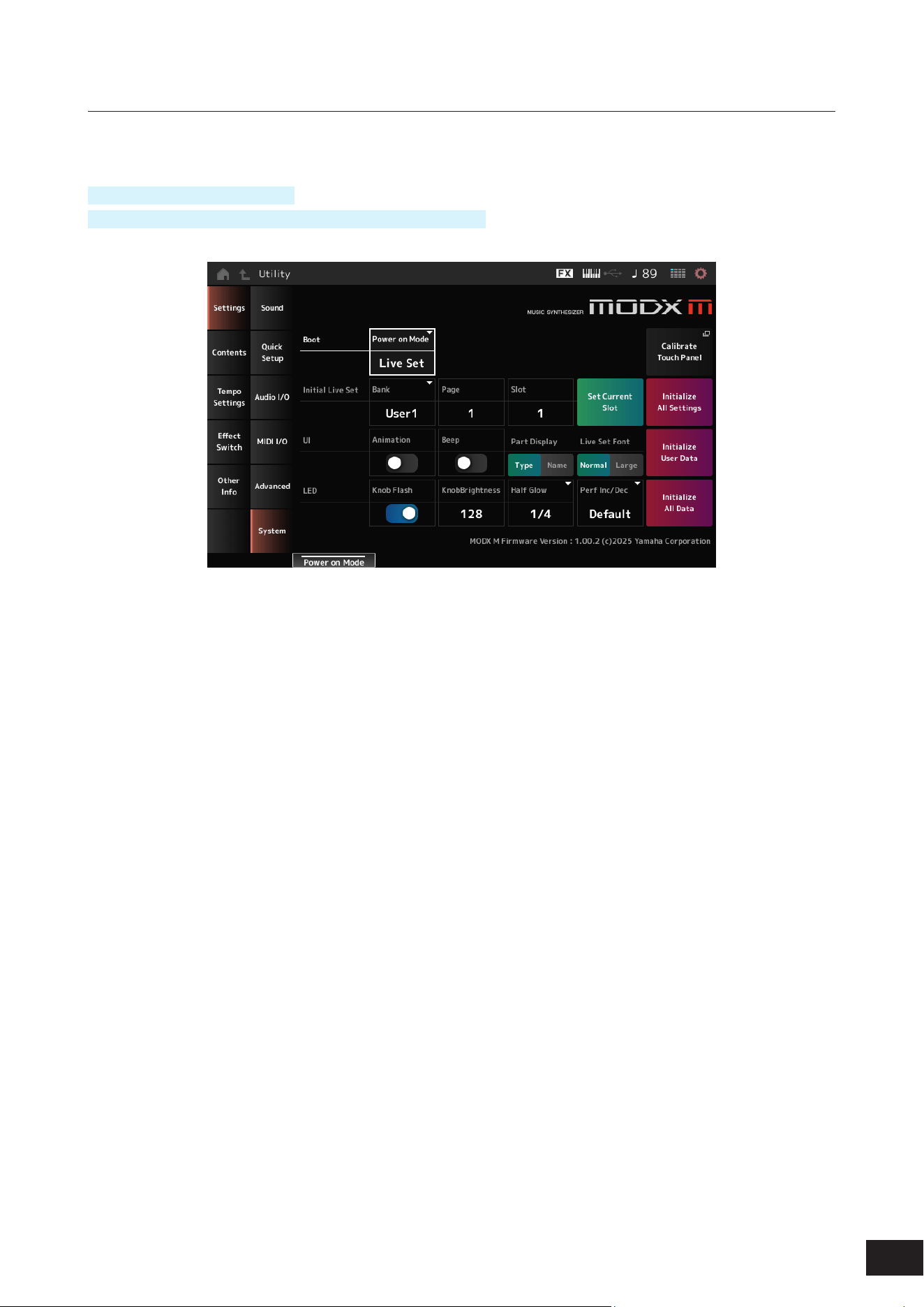
373
MODX M Operation Manual
System
On the System screen, you can set the parameters related to the entire instrument.
Operation
[UTILITY]
→
Settings
→
System
[UTILITY] + [DAW REMOTE] (
→
Calibrate Touch Panel setting)
Power on Mode
Sets the screen to be shown on the display when the instrument is turned on.
Settings: Perform, Live Set
Calibrate Touch Panel
Opens the screen for touchscreen calibration. Use it when the touchscreen does not respond correctly.
Initial Live Set Bank (Initial Live Set Bank)
Initial Live Set Page (Initial Live Set Page)
Initial Live Set Slot (Initial Live Set Slot)
When Power on Mode is set to Live Set, this determines the live set slot to be selected immediately after startup.
NOTE
You can also set the slot by selecting a Performance on the Live Set screen, opening this screen, and then tapping the Set Current Slot
button.
Set Current Slot (Set Current Slot to Initial Live Set)
Sets the current Performance to the Live Set slot selected after startup.
Initialize All Settings
Initializes all Utility screen settings.
Animation
Sets whether animation is On or Off when the screen switches.
Settings: Off, On

374
MODX M Operation Manual
Beep
Turns the touchscreen operation sound on or off.
Settings: Off, On
Part Display
Sets the Part Name to show the Category and Part Type or just Part Name.
Settings: Type, Name
Live Set Font
Determines the font size of the contents names and category names on the Live Set screen and the Category Search
screen.
Settings: Normal, Large
Initialize User Data
Initializes all user area data in user memory (performance, motion sequences, live sets, etc.) and all settings on the Utility
screen.
Knob Flash (Super Knob LED Blink)
Sets the ashing of the Super Knob on or off.
Settings: Off, On
KnobBrightness
Sets the brightness of lighting on the Super Knob.
Settings: 0–128
Half Glow (LED Half Glow Brightness)
Controls the dimming of the button lamps.
Settings: Off, 1/4, 1/2
Perf Inc/Dec
Sets how performance is switched on the Home screen.
Settings: Default, Live Set
Default: Switches in the order of the Performance list on the Performance Category Search screen
Live Set: Switches in the order of the Live Set slots
Initialize All Data
Initializes all data in User memory and Utility screen settings.
Product Info
Shows the rmware version of the instrument.
NOTICE
Initializing will overwrite all of the target data and system settings to the factory settings.
Be careful not to lose important data. It is also recommended to save the necessary settings to a USB flash drive in advance.
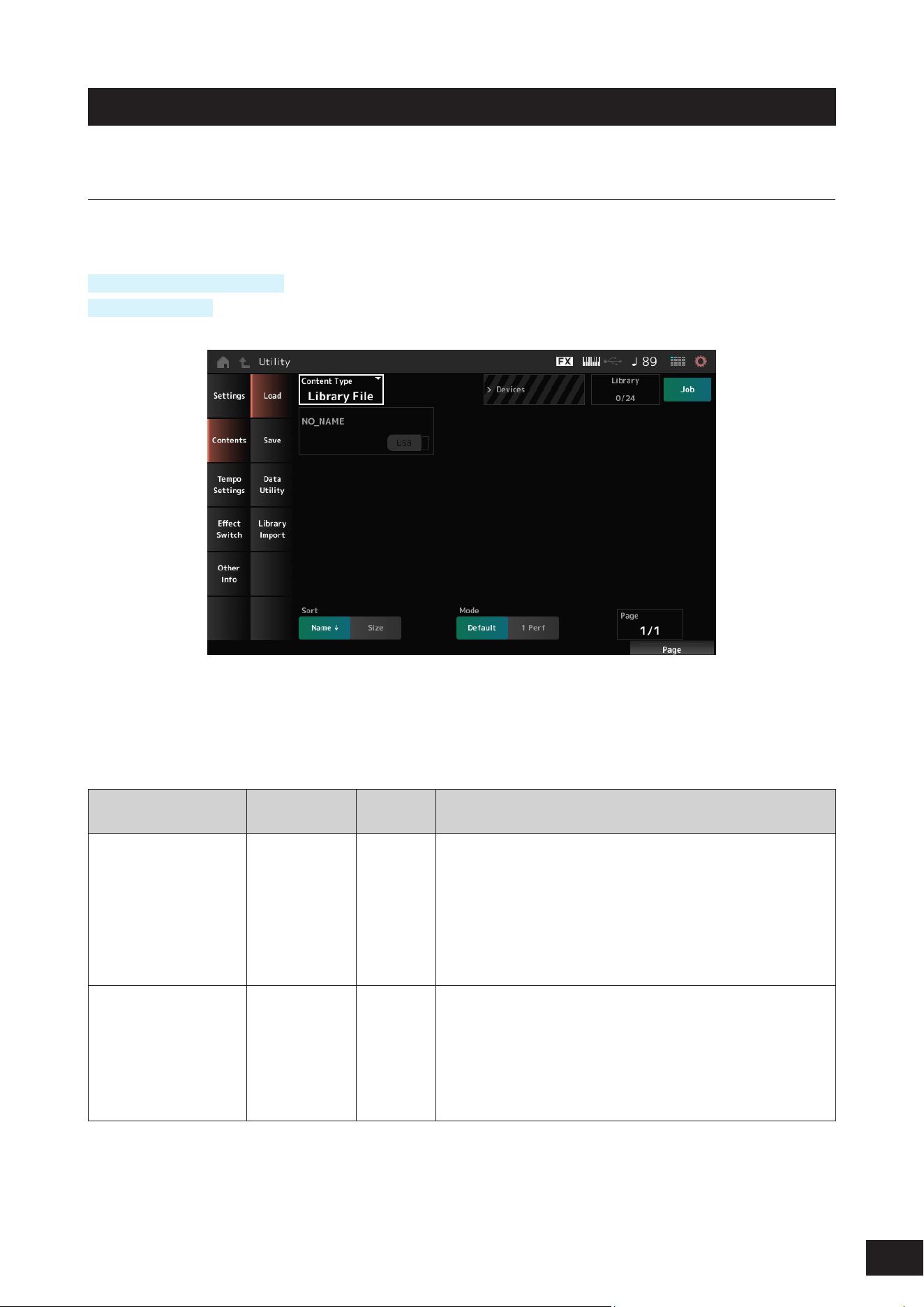
375
MODX M Operation Manual
Contents
Load
Files and internal data are loaded using the Load screen.
Operation
[UTILITY]
→
Contents
→
Load
[SHIFT] + [STORE]
Content Type
All data or a specic set of data is loaded from a single le saved on a USB ash drive or setting stored on the instrument.
Here, you can select which set of data in a le to load.
Available settings vary depending on the route you take to open the screen.
Settings: The le types which can be loaded are as follows.
Content Type Device Type
File
extension
Description
User File File .Y2U
(.Y2W )
.X7U
.X8U
• User les saved on a USB drive are loaded into the user area of user
memory.
• If the user le has been split, both the .Y2U and .Y2W must be stored
on the USB drive.
• The following settings are included in a User le.
Performance, Arpeggio, Motion Sequence, Curve, Live Set,
Microtuning, Waveform, Audition, Utility Settings (.Y2U only), Quick
Setup (.Y2U only)
Library File File .Y2L
(.Y2M)
.X7L
.X8L
• Library les saved on a USB drive are loaded into the Library area of
User memory.
• If a Library le has been split both .Y2L and .Y2M must be saved on
the USB drive.
• The following settings are included in a Library le.
Performance, Arpeggio, Motion Sequence, Curve, Live Set (1 bank
only), Microtuning, Waveform, Audition
376
MODX M Operation Manual
Content Type Device Type
File
extension
Description
Backup File File .Y2 A
(.Y2B)
.X7A
.X8A
• Backup les saved on a USB drive are loaded into the User memory.
• A backup le includes everything in the User and Library areas, as
well as Songs, and Patterns.
• If a backup le has been split, both .Y2A and .Y2B must be saved on
the USB drive.
Song&Perf
(Song & Performance)
Internal data • Only the specied Song is loaded from Songs stored in the User
area of the User memory.
• Both MIDI sequences and Performances can be loaded.
Song Internal data • Only the specied Song is loaded from Songs stored in the User
area of the User memory.
• Only MIDI sequences can be loaded.
.mid File File .MID Standard MIDI Files (SMF) saved on a USB drive are loaded (either in
format 0 or format 1).
.wav File File .WAV Audio les saved on a USB drive are loaded.
Pattern&Perf
(Pattern & Performance)
Internal data • Only the specied Pattern is loaded from Patterns stored in the User
area of the User memory.
• Both MIDI sequences and Performances can be loaded.
Pattern Internal data • Only the specied Pattern is loaded from Patterns stored in the User
area of the User memory.
• Only MIDI sequences can be loaded.
Audio File* File .WAV
.AIF
Audio les saved on a USB drive are loaded as Waveforms.
Example: [PERFORMANCE (HOME)]
→
[EDIT/
]
→
Part selection
→
Element selection
→
Osc/ Tune
Motion Seq
(Motion Sequence)*
Internal data Only the specied sequence is loaded from the Motion Sequences
saved (stored) in the User area of the User memory.
Smart Morph* Internal data Only Smart Morph data is loaded from the Performance saved (stored)
in the User area of User memory.
NOTE
Content types marked with an asterisk (*) are not displayed when this screen is opened from the Utility screen.
Parent Folder Name
Current Folder Name
Indicates the name of the parent folder and the name of the current folder.
Once you tap on the parent folder name, it is then the current folder.
Job
Sets whether the Job function is enabled (On) or disabled (Off).
When this parameter is turned On, tapping on the current le, folder, or content will call up the Rename or Delete context
menu.
Tapping on the connected USB ash drive, will call up the Format context menu.
Settings: Off, On

377
MODX M Operation Manual
Free Storage
Indicates the used capacity and total capacity of the selected storage.
The indication differs depending on the content type.
Folder file select
Indicates the folders and les within the current folder.
Sort
Set the sort order for the les in le select.
Settings: Name, Size, Date, Default (depending on content type)
Name: Sorts by name. The down arrow indicates that the list is arranged in ascending order (A to Z). The up arrow indicates
that the list is arranged in descending order.
Size: Sorts in order of data size. The down arrow indicates that the list is in ascending order (small to large). The up arrow
indicates that the list is in descending order. Invalid for content types Motion Seq, Song, Song&Perf, Pattern, Pattern&Perf,
Performance, Smart Morph
Date: Sorts by date the setting was stored. The down arrow indicates that the list is arranged in descending order (new to old).
The up arrow indicates that the list is arranged in ascending order. This is available only when the content type is Motion Seq,
Song, Song&Perf, Pattern, Pattern&Perf, Performance, Smart Morph
Default: Sorts in ascending order of content number. This is available only when the content type is Song, Song&Perf,
Pattern, Pattern&Perf, Performance, Motion Seq, Smart Morph
Mode
Selects the mode for loading.
This is displayed only for a User File or a Library File.
Settings: Default, 1 Perf
Default: Loads all Performances
1 Perf: Loads only a specied Performance
Key (Center Key)
Select the key to which the loaded WAV or AIFF is to be assigned.
This is shown only for audio les.
Settings: Keyboard Select (C−2 −G8), All
Keyboard Select
Set whether Center Key is updated by keyboard operation.
This is shown only for audio les.
Page
If the les appearing in the le select cannot t on a single page, a scroll button will appear to allow you to select a page.
Alternately you can use a Display knob to select a page.
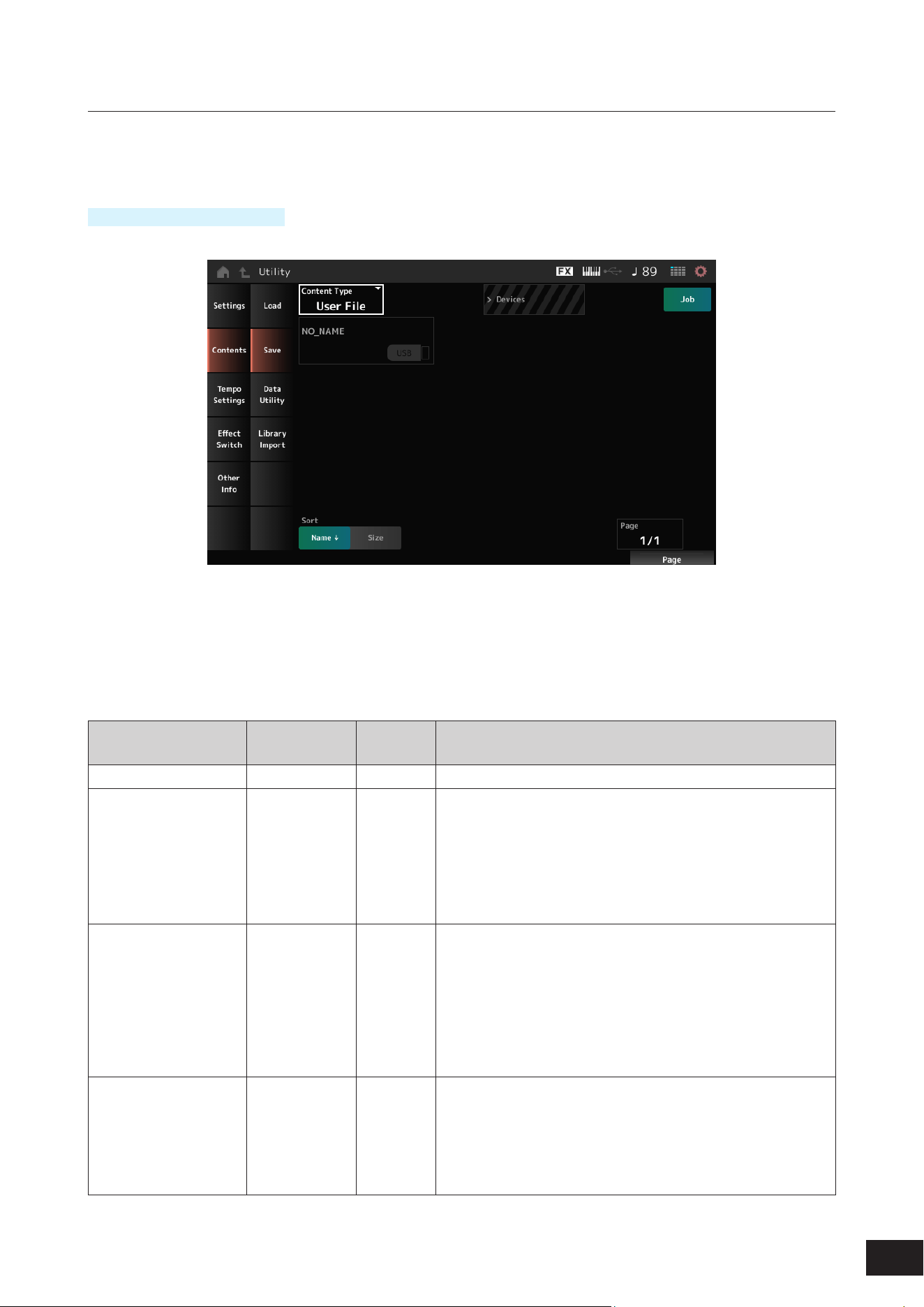
378
MODX M Operation Manual
Save
On the Save screen, you can save les and internal data.
This is basically the same as the Load screen.
Operation
[UTILITY]
→
Contents
→
Save
Content Type
All data or a specied portion of data from les stored on a USB drive or the main unit can be retrieved and loaded into
the instrument.
Here, you can set which data to store or save.
Available settings vary depending on the route you take to open the screen.
Settings: The following table shows the content types that can be stored or saved.
Content Type Device Type
File
extension
Description
Performance Internal data Saves (Stores) the Performance to the User area of the User memory.
User File File .Y2U
(.Y2W )
• Settings saved (stored) in the User area of User memory are saved
to a USB drive as a User le.
• The following settings are included in a User le.
Performance, Arpeggio, Motion Sequence, Curve, Live Set,
Microtuning, Waveform, Audition, Utility Settings, Quick Setup
• When the le size exceeds 2 GB and the le has been divided, both
.Y2U and .Y2W must be handled as a set.
Library File File .Y2L
(.Y2M)
• Settings saved (stored) in the Library area of User memory are
saved to a USB drive as a Library le.
• The settings contained in the Library le are as follows (same as the
User File, except for the utility settings):
Performance, Arpeggio, Motion Sequence, Curve, Live Set (1 bank
only), Microtuning, Waveform, Audition
• When the le size exceeds 2 GB and the le has been divided, both
.Y2L and .Y2M must be handled as a set.
Backup File File .Y2 A
(.Y2B)
• Settings stored in the User memory are saved to a USB drive as a
backup le.
• A backup le includes everything in the User and Library areas, as
well as Songs, and Patterns.
• When the le size exceeds 2 GB and the le has been divided, both
.Y2A and .Y2B must be handled as a set.

379
MODX M Operation Manual
Content Type Device Type
File
extension
Description
.mid File File .MID MIDI data stored in the Song and Pattern area of User memory is
saved to a USB drive as a Standard MIDI File (SMF; only in format 1).
Motion Seq
(Motion Sequence)*
Internal data Stores (saves) the Motion Sequence being edited to the User area.
NOTE
Content types marked with an asterisk (*) are not displayed when this screen is opened from the Utility screen.
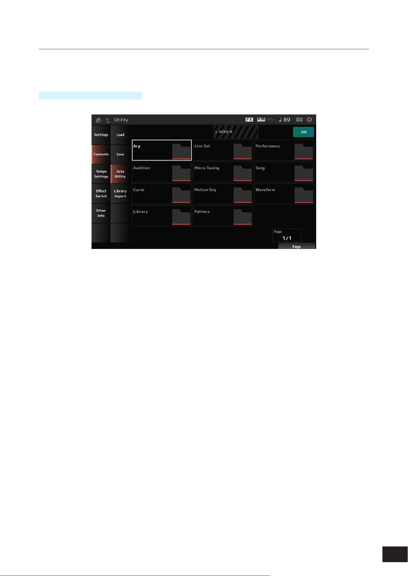
380
MODX M Operation Manual
Data Utility
On the Data Utility screen, you can manage les and data in User memory.
This is basically the same as the Load screen.
Operation
[UTILITY]
→
Contents
→
Data Utility
Folder select
Shows the Content types in User memory as folders. Tap the folder to open.
Content Type: Arp, Audition, Curve, Library, Live Set, Micro Tuning, Motion Seq, Pattern, Performance, Song, Waveform
Content Select
Tapping the content calls up the Rename, Delete context menu.
When Job is set to On, the following three items are displayed.
Select All
Selects all of the contents in the folder.
Displayed when nothing has been selected.
Unselect All
Unselects all of the contents in the folder.
Displayed when any of the contents have been selected.
Delete
Deletes all selected content.
Displayed when any of the contents have been selected
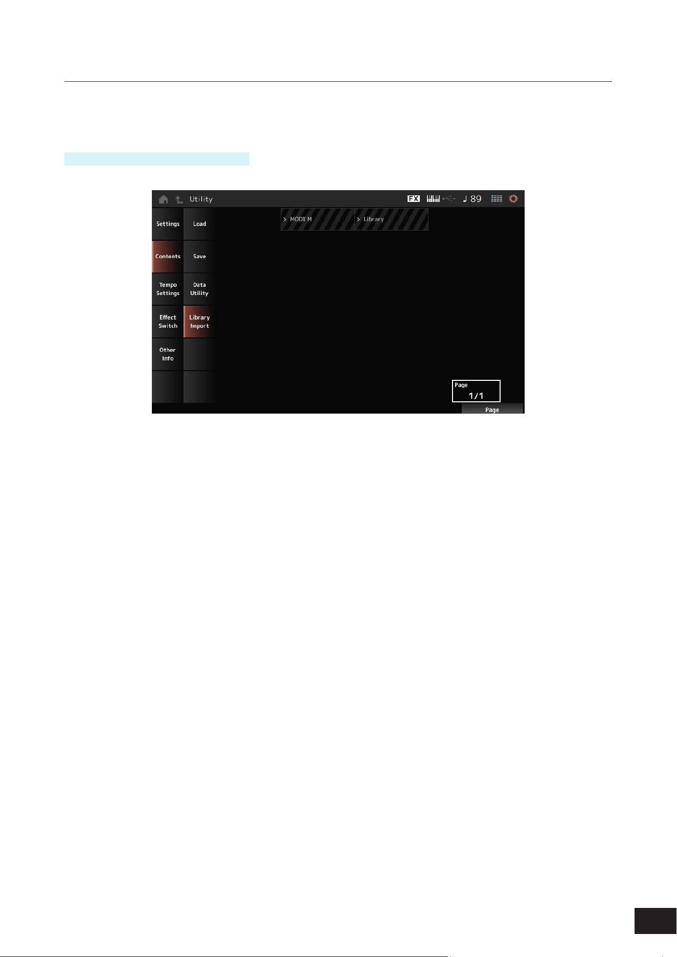
381
MODX M Operation Manual
Library Import
This function selects a specic performance from the library and copies it to the user bank.
This is basically the same as the Load screen.
Operation
[UTILITY]
→
Contents
→
Library Import
Select All
Selects all Performances in the current library folder.
Shown only when no Performance has been selected.
Unselect All
Deselects all Performances in the current library folder.
Displayed only when any Performance has been selected.
Import to User Bank
Copies the selected Performance to the User Bank.
When this operation is carried out, the User Waveforms and User Arpeggios, User Curves, User Micro Tuning, and User
Auditions used in the selected Performance are also copied to the User Bank.
Displayed only when any performance has been selected.
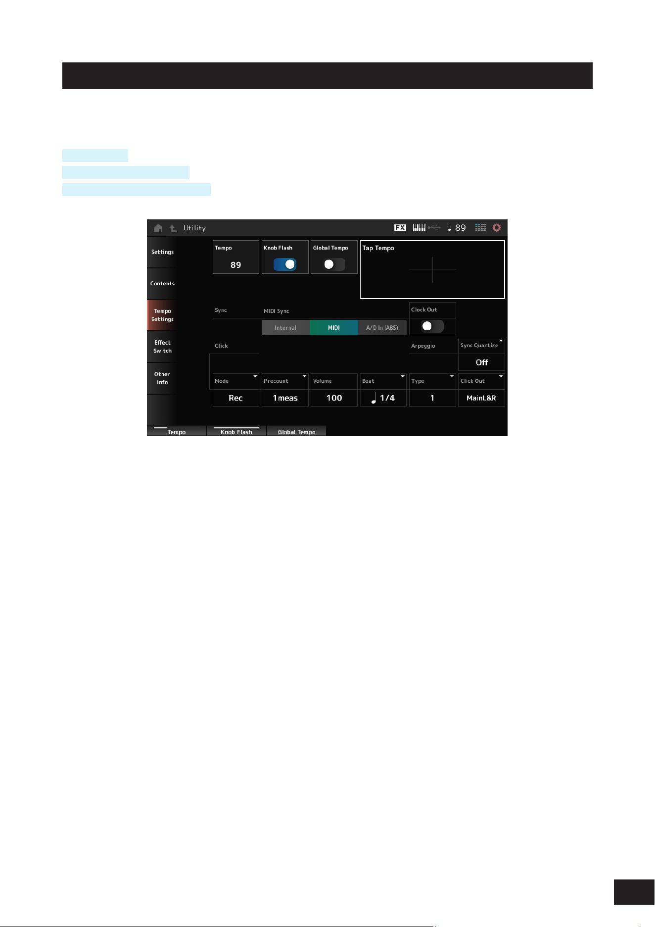
382
MODX M Operation Manual
Tempo Settings
On the Tempo Settings screen, you can set the parameters related to tempo and synchronization.
Operation
[TEMPO/TAP]
[UTILITY] + Tempo Settings
Tap the TEMPO SETTINGS icon
Tempo
Sets the Performance tempo.
If MIDI Sync is set to MIDI or A/D In (ABS) and is synchronized with an external device, Ex.Tempo will be displayed instead
of the setting value.
Settings: 5–300
Knob Flash (Super Knob LED Blink)
Sets the ashing of the Super Knob On or Off.
Settings: Off, On
Global Tempo
When this parameter is set to Off, the Tempo setting for each Performance is used.
When set to On, the current tempo is retained even when you change the Performance.
Settings: Off, On
Tap Tempo
By tapping this area or by pressing (tapping) the [ENTER] button while the cursor is present, you can set the tempo to the
tap or press speed.
Or you can use the [TEMPO/TAP] button to set the tempo in the same way.
However, this parameter is not available when MIDI Sync is set to MIDI and the instrument is set to synchronize to an
external device.
NOTE
If MIDI Sync is set to “A/D In (ABS)”, the tempo is changed with the tap serving as the beginning of the beat.

383
MODX M Operation Manual
MIDI Sync
Sets the parameters related to synchronization to the connected external device.
You can choose whether to play Arpeggio, Motion Sequencer, and Song using the internal clock of the instrument, using
the clock (external clock) of the DAW software or MIDI devices connected to this unit, or using audio signals input from
the A/D INPUT terminal.
Settings: Internal, MIDI, A/D In (ABS)
Internal: Synchronizes to the internal clock. For using this instrument by itself or as the master clock source for other devices.
MIDI: Synchronizes to the MIDI clock received from the external MIDI device. For using the external device as the master
clock source.
A/D In (ABS): Operates by extracting the tempo from the audio signal input from the A/D INPUT terminal using the Audio
Beat Sync function.
Clock Out (MIDI Clock Out)
Sets the MIDI clock messages to be transmitted.
Settings: Off, On
Sync Quantize (Arpeggio Synchro Quantize Value)
Adjusts the timing for starting the next Arpeggio if playing back an Arpeggio for multiple Parts. When set to Off, the
Arpeggio is played back when the Part is played on the keyboard.
Settings: "Off, 60 (thirty-second note), 80 (sixteenth note triplet), 120 (sixteenth note), 160 (eighth note triplet), 240 (eighth note),
320(quarter note triplet), 480 (quarter note)"
Mode (Click Mode)
Set the timing for when the click sound (metronome sound) is played.
Settings: Off, Rec, Rec/Play, Always
Off: No click sound is played.
Rec: The click sound is played during Song or Pattern recording.
Rec/Play: The click sound is played during Song or Pattern recording and playback.
Always: The click sound is always played.
NOTE
The click sound is played using an internal tone generator, so some of the simultaneous sound output will be consumed.
Precount (Click Precount)
Sets the number of count-in measures from the time the [
] (Play) button is pressed until recording actually starts when
recording a Song or Pattern.
Settings: Off (recording starts as soon as you press the [
] (Play) button), 1meas–8meas
Volume (Click Volume)
Sets the volume for the click sound.
Settings: 0–127
Beat (Click Beat)
Sets the beat at which the click sound is played.
Settings: 1/16 (sixteenth notes), 1/8 (eighth notes), 1/4 (quarter notes), 1/2 (half notes), Whole (whole notes)
Type (Click Type)
Selects the type of click sound.
Settings: 1–10
Click Out (Click Output Select)
Sets the output destination for the click sound.
Settings: MainL&R, (AsgnL&R), USB Stereo, (AsgnL), (AsgnR), USB mono
MainL&R: Outputs in stereo (two channels) to the OUTPUT [L/MONO] and OUTPUT [R] jacks.
USB Stereo: Outputs in stereo (channels 1 and 2, to channels 7 and 8) to the USB [TO HOST] terminal
USB mono: Outputs in mono (channels 1 to 8) to the USB [TO HOST] terminal
NOTE
The settings for data compatibility with MONTAGE M are shown below. They are considered Off when set.
• AsgnL&R
• USB Stereo: USB9&10 – USB29&30
• USB mono: USB9 – USB30
• AsgnL
• AsgnR
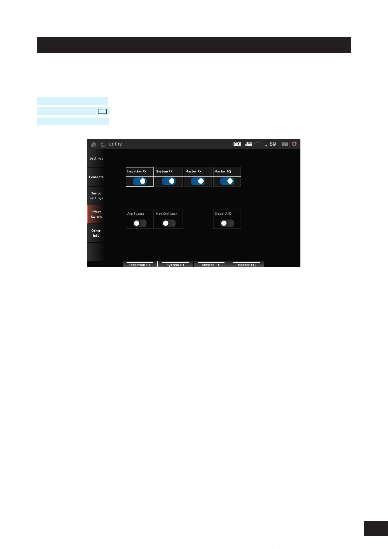
384
MODX M Operation Manual
Effect Switch
On the Effect Switch screen, you can set the parameters related to effect bypass.
The settings on this screen are not saved (stored), so the settings are reset to the default when the instrument is restarted.
Operation
[UTILITY]
→
Effect Switch
Tap the EFFECT icon (
FX
)
[SHIFT] + [QUICK SETUP]
Insertion FX (Insertion Effect)
Sets the Insertion Effect on or off.
Settings: Off, On
System FX (System Effect)
Sets the System Effect on or off.
Settings: Off, On
Master FX (Master Effect)
Sets the Master Effect on or off.
Settings: Off, On
Master EQ
Sets the Master EQ on or off.
Settings: Off, On
Arp Bypass (Arpeggio Bypass)
Sets the Arpeggio Bypass on or off. When this parameter is set to On, all Arpeggio operations are disabled.
Settings: Off, On
NOTE
• When Arp Bypass On, the [ARP] button ashes.
• When Arp Bypass is set to On, if you change the Arpeggio Switch for each Part, Arp Bypass will be set to Off.
• The Songs recorded by using the Arpeggio function will have the Arpeggio sequence included in the data. If you continue to edit the
song data in the DAW software, setting Arp Bypass to On prevents the arpeggiator from having a double effect.

385
MODX M Operation Manual
Kbd Ctrl Lock (Keyboard Control Lock)
Sets lock for the Keyboard Control on or off.
When set to On, the lock is activated and Keyboard Control for all parts is disabled. Turning it off unlocks Keyboard
Control.
This is useful for creating or editing each MIDI track separately, for example, when using the instrument as a 16-part multi-
timbral sound module with the DAW software.
Settings: Off, On
NOTE
When Kbd Ctrl Lock is On, if you change Keyboard Control SW of each part, Kbd Ctrl Lock will be set to Off.
Global A/D
When this parameter is set to On, the volume of the A/D Part does not change when switching between performances,
and other parameters related to the A/D part do not change. When this parameter is set to Off, the volume changes to a
performance-specic setting when switching between performances, and other parameters related to the A/D part will
change.
Master FX and Master EQ are switched on and off simultaneously.
Settings: Off, On

386
MODX M Operation Manual
Other Info
Other information is displayed on the Other Info screen.
Shift Function
Shows the list of shortcut operations for simultaneous pressing of the [SHIFT] button and other buttons.
Legal Notices
Shows content such as copyrights.

387
MODX M Operation Manual
Screens shown by pressing specific buttons
Panel Lock
Using the panel lock function prevents accidental operation during live performances.
Operation
When the Home screen or the Live Set screen is shown, press [SHIFT]+[TEMPO/TAP]
Valid operations
Keyboard, pedals, Master Volume, Super Knob, Pitch bend wheel, Modulation wheel, Ribbon controller, and panel lock
disengage
Invalid operation
All other operations, including touchscreen operations
How to disengage the panel lock
To unlock the panel, hold the [SHIFT] button again while tapping the [TEMPO/TAP] button to unlock the panel.
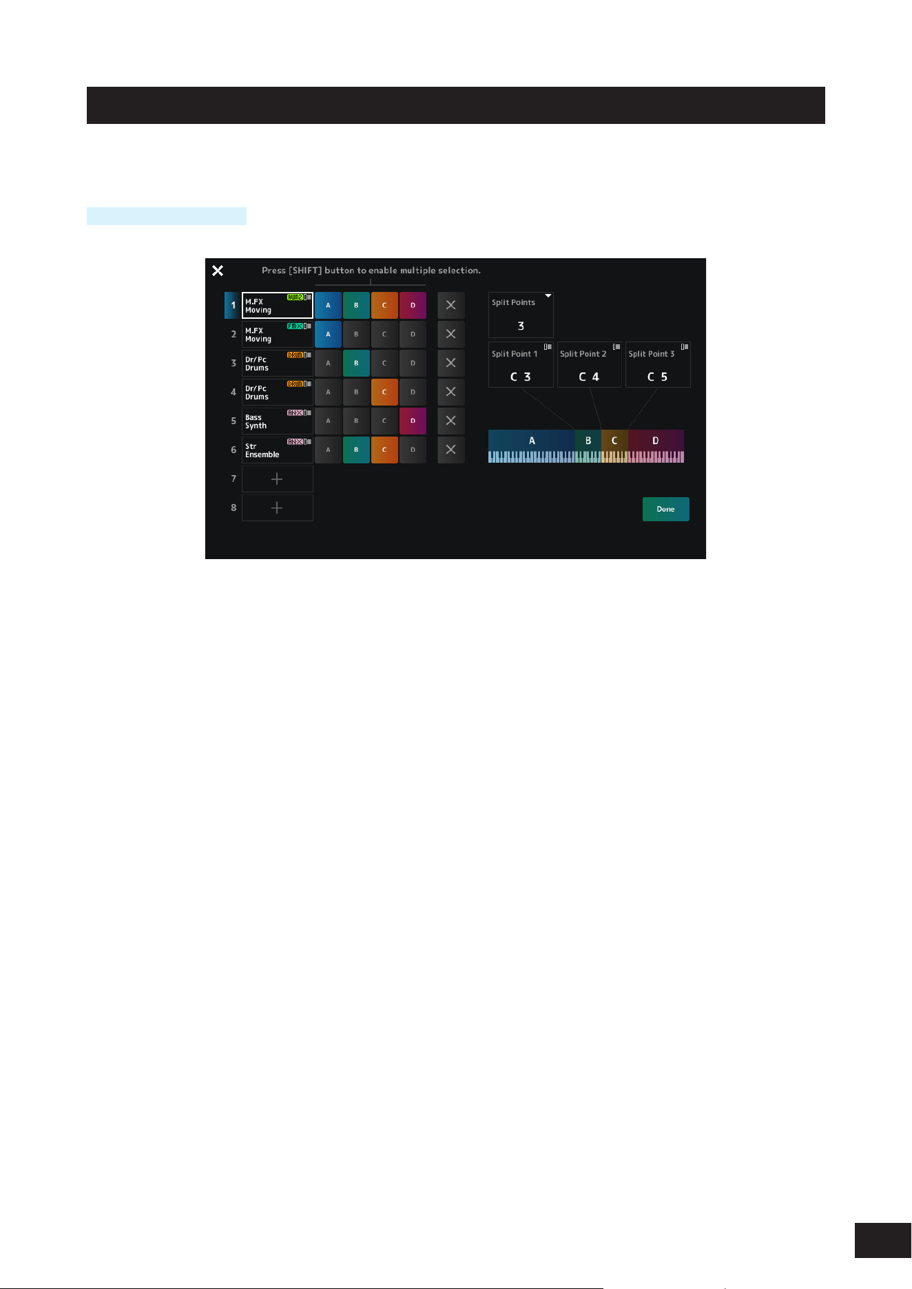
388
MODX M Operation Manual
Split Job
Sets the split.
Operation
Press the [SPLIT] button.
Split Points
Species the number of split points.
Settings: Off, 1–3
Split Point 1–3
Species the key for the split point.
When Keyboard is set to On, you can also specify the split point position using the keyboard.
Settings: C#−2 – G8
Part Name
Tapping on the Part name calls up the context menu for Category Search and Delete.
[+](Add)
Tap to display the Part Category Search screen or Performance Merge screen, which allows you to add a Part.
Group A–D
Press a Group button to assign the Part to the group.
Tap the group buttons while holding down the [SHIFT] button to assign a single Part to multiple groups.
× (Cancel)
Cancels group assignments.
Done
Conrms the settings and closes the screen.
NOTE
Tapping the × (close) on the upper left closes the screen without conrming settings other than adding, deleting, or changing parts.
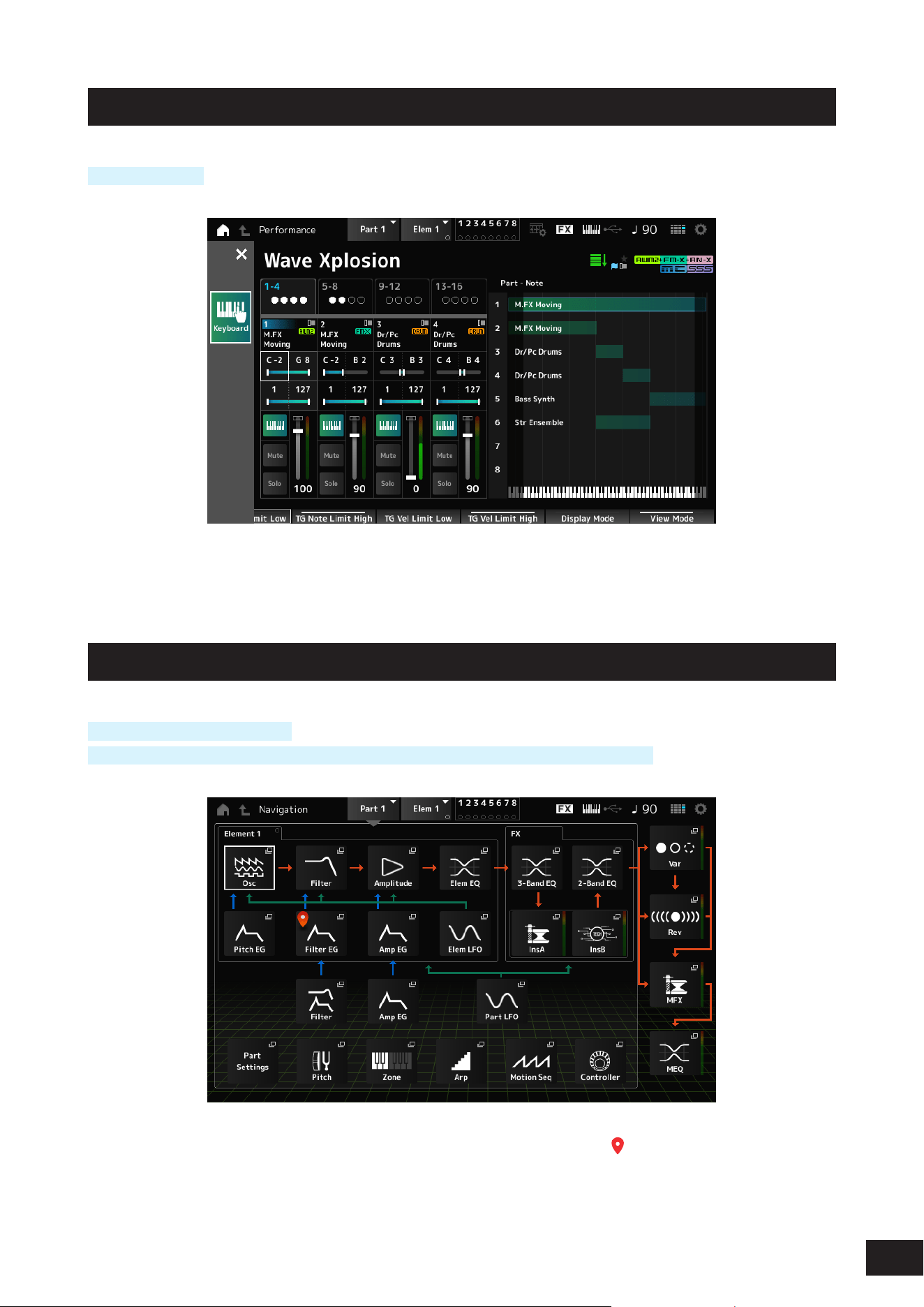
389
MODX M Operation Manual
Note Range
Operation
[SHIFT] + [SPLIT]
The Part - Note view is shown on the Home screen.
The cursor will move to TG Note Limit Low of the selected part, and you can enter the lower limit of the note range on the
keyboard.
Navigation
Operation
Press the [NAVIGATION] button
(With the (Home screen View Modeset to Default) Tap Navigation displayed on the screen
Tapping the icons calls up the corresponding setting screens.
Pressing the [NAVIGATION] button during editing calls up the current location icon (
).
From the Navigation screen, you can jump not only to elements, but also to the Part Common's Filter and Amp EG.
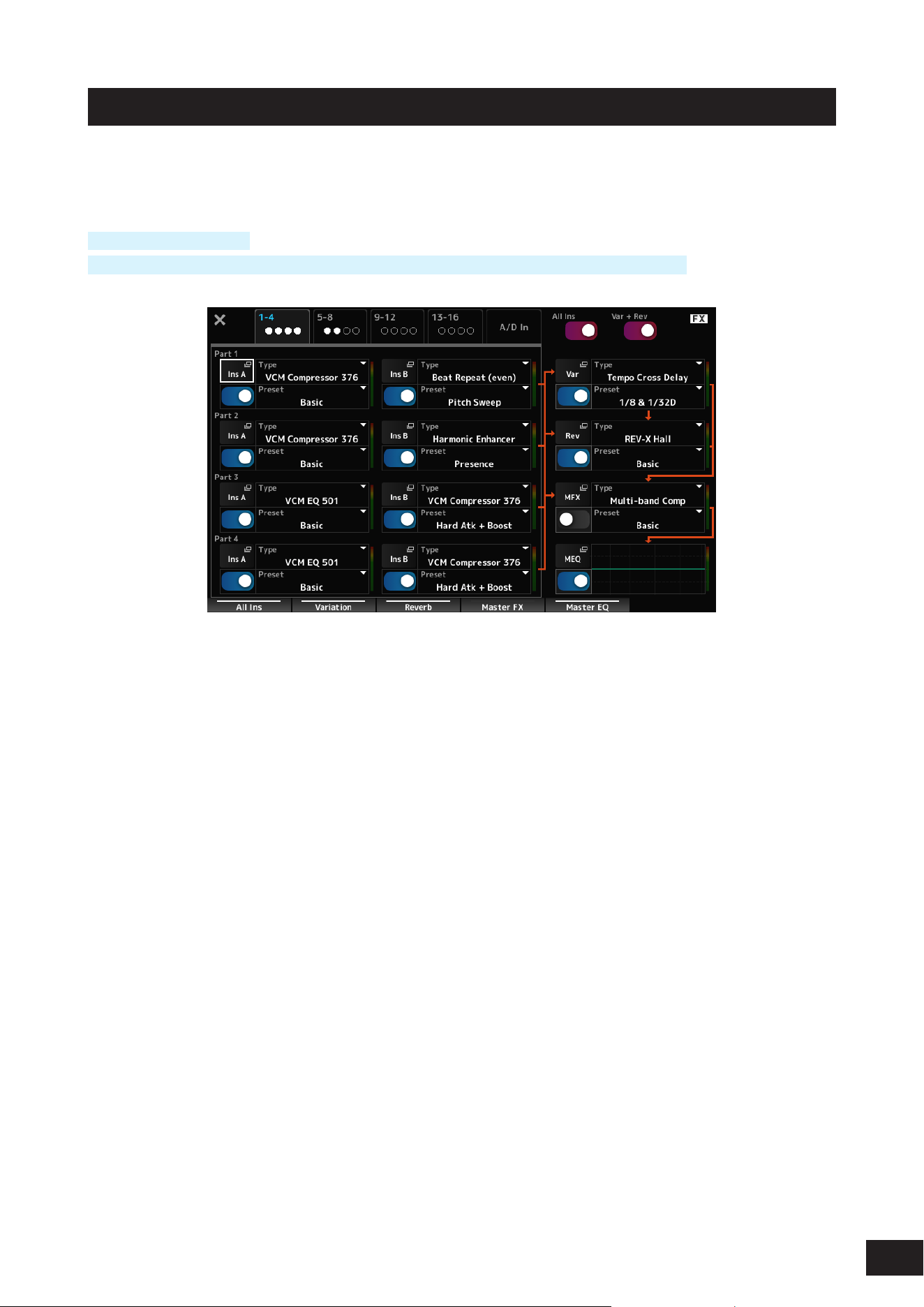
390
MODX M Operation Manual
FX Overview
On the FX OVERVIEW screen, you can check the status of effect settings and easily access screens for advanced
settings.
Operation
[SHIFT] + [NAVIGATION]
(With the Home screen View Mode set to Default) Tap the Fx Overview displayed on the screen
Switching Parts for display
Switches the Parts to display.
Settings: 1–4, 5–8, 9–12, 13–16, A/D In
All Ins
Turns all Insertion Effects (A and B) on or off.
Settings: Off, On
Var + Rev
Turns the Variation and Reverb effects on or off.
Settings: Off, On
Ins A, Ins B, Var, Rev, MFX, MEQ
Shows the corresponding screen for detailed settings.
Effect switch
Switches each effect on or off.
Settings: Off, On
Type
Sets the type for each effect.
Settings: Refer to the Effect types
Preset
Sets the preset for each effect.
Settings: Refer to the Data List

391
MODX M Operation Manual
Store
This is the conrmation screen when saving (storing) the current Performance in the User area.
Store As New Performance
Registers as a new Performance.
Update Current Live Set Slot
When a slot in the User Live Set bank is selected, a message conrming the update of the Live Set slot will appear. To
proceed with the update, check the box and select Store As New Performance.
Overwrite Current Perf.
Saves the Performance you are editing over the existing settings (Bank, MSB, LSB, and Program Change number) shown
on the display.
Jump to Data Utility
Displayed when saving is not possible due to an error such as Performance full.
Use [UTILITY]
→
Contents
→
Data Utility to display the screen.
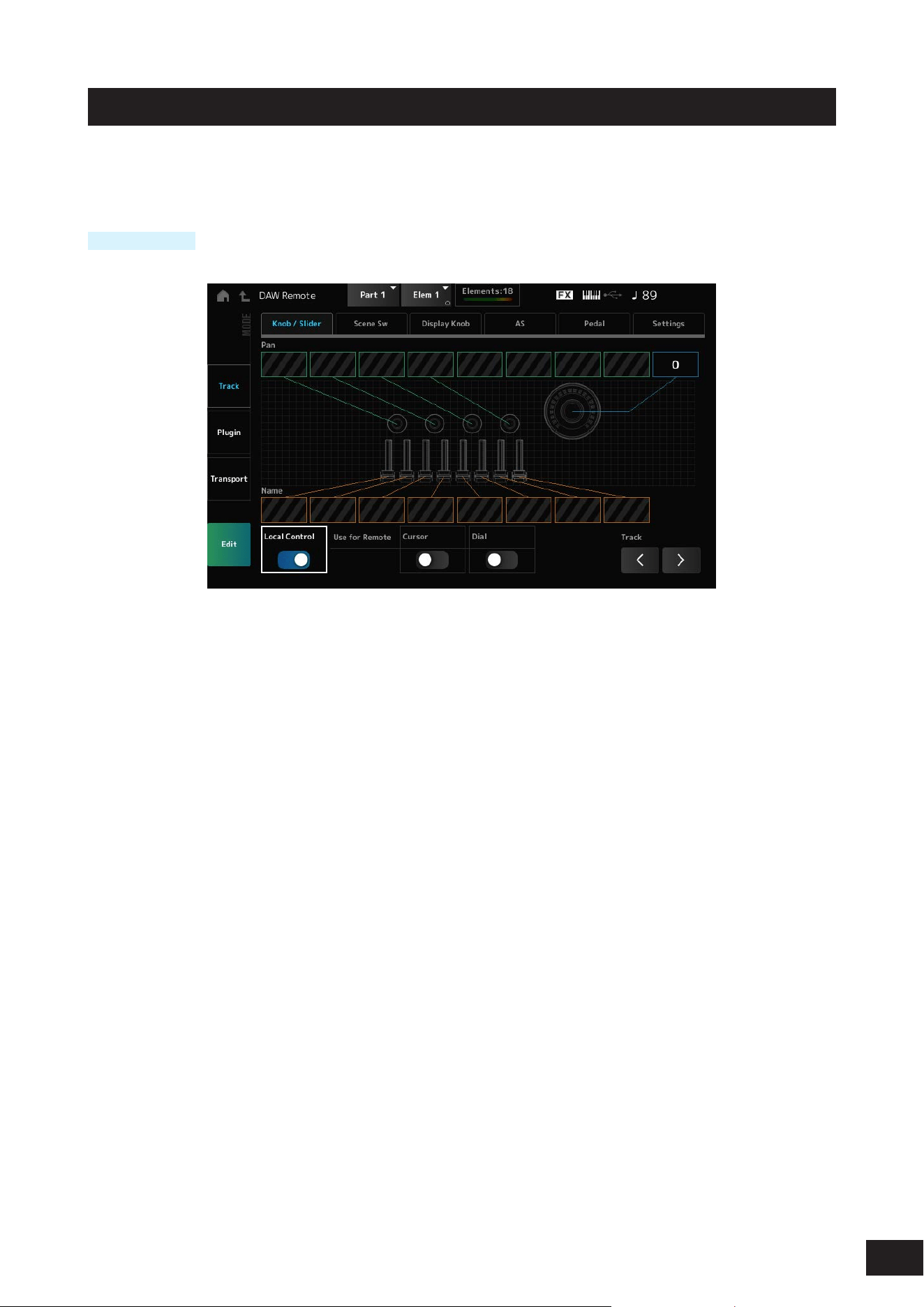
392
MODX M Operation Manual
DAW Remote
Pressing the [DAW REMOTE] button enables the DAW remote function, allowing you to conveniently control your
preferred DAW with the controllers on the instrument.
Operation
[DAW REMOTE]
Mode (Remote Control Mode)
Select the DAW remote function from three modes of operation.
Settings: Track, Plugin, Transport
Track: Mode for controlling multiple tracks on the DAW at once. Knob and control slider operations are sent as Mackie Control
compatible protocols from Port 2.
Plugin: Mode for controlling a specic plugin on the DAW. Knob and control slider operations are sent as messages in CC
Number format for Remote functions from Port 1.
Transport: Mode for playing the keyboard while playing back the recorded data on the DAW, or recording your keyboard
performance on the DAW. You can use the Sequencer transport buttons to start or stop the playback on the DAW. All
controllers except the Sequencer transport buttons operate as they normally do.
Switching screens
Opens the settings screen for each controller and the remote function.
Settings: Knob/Slider, Scene Sw, Display Knob, AS, Pedal, Settings
Local Control
Sets Local Control On or Off.
This is the same as what can be set in [UTILITY]
→
Settings
→
MIDI I/O.
Use for Remote Cursor / Dial
Sets whether to use the Data dial and Cursor buttons on the Top panel for controlling the DAW.
On: For controlling the DAW.
Off: For controlling the Main display on the top panel.
Track (Track Select)
Outputs the Track group selection (by eight tracks at a time).
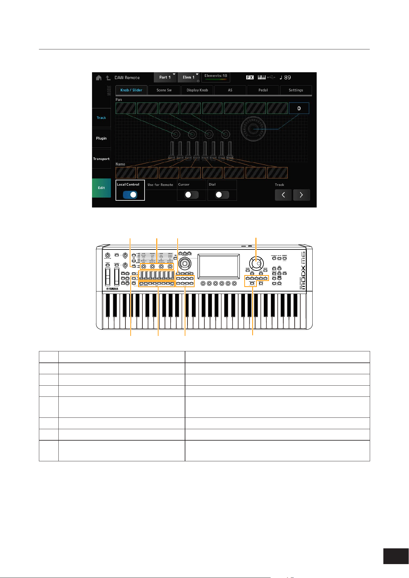
393
MODX M Operation Manual
For using controllers
Track mode
Controllers
(1) (2)
(3) (4)
(5)
(6)
(7)
(4)
Controllers DAW operation
(1) [ASSIGN] button Pan selection (1 – 4 / 5 – 8)
(2) Knob 1 – 4 (5 – 8) Track Pan is output from Port2
(3) Control sliders 1–8 Track volume is output from Port2
(4) PART button, [PART SELECT] button Selects track(s), and switches mute and solo of the selected
track(s) on or off.
(5) SCENE buttons Functions 1 – 8 are output from Port2
(6) Data dial, cursor buttons Moves the cursor position or Song position.
(7) Sequencer transport button.
[SONG/PATTERN] button
Controls the transport actions (recording and playback).
Other controllers are set to send the Control Change messages set in remote mode.
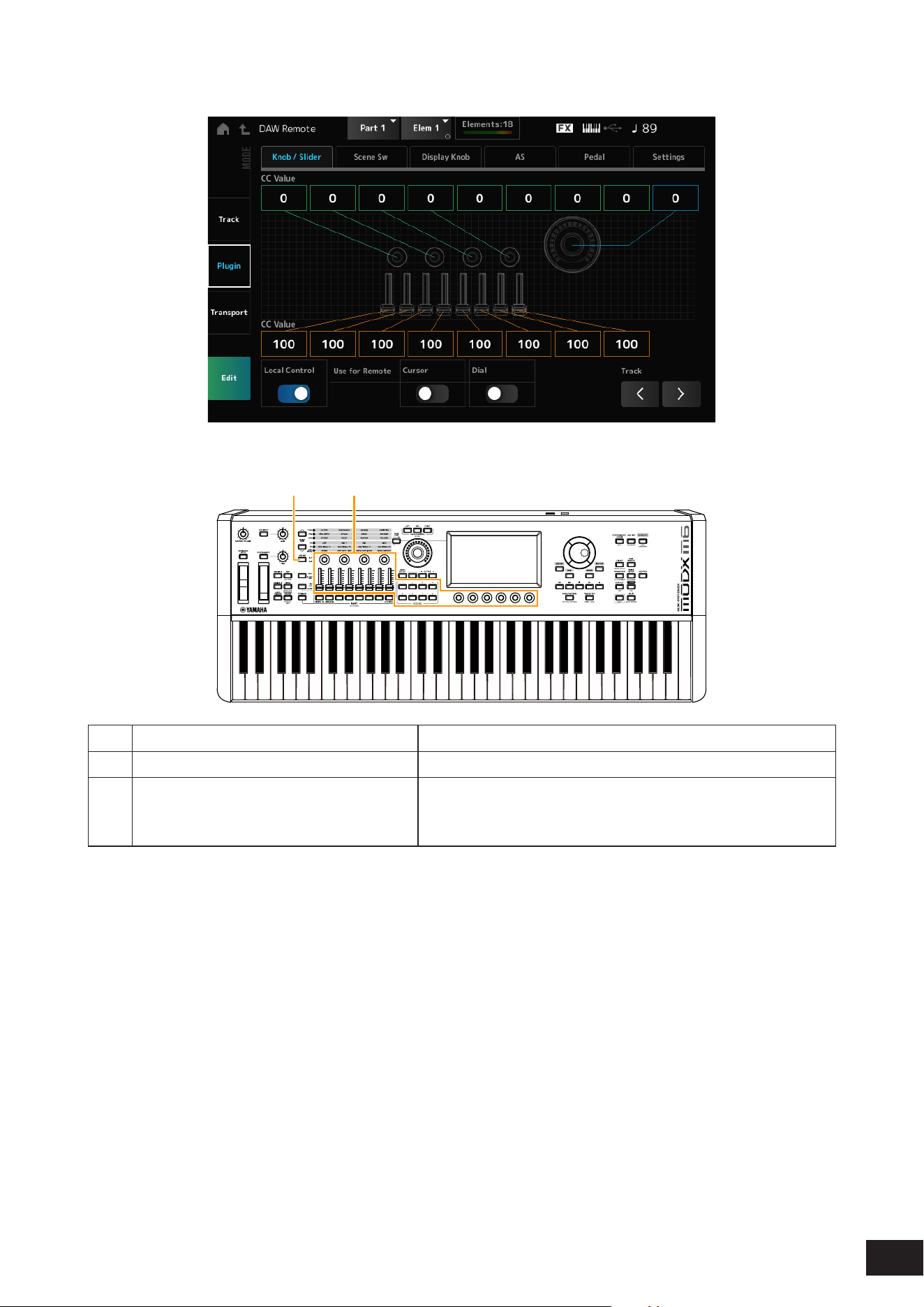
394
MODX M Operation Manual
Plugin mode
Controllers
(1) (2)
Controllers DAW operation
(1) [ASSIGN] button Knob selection (1 – 4 / 5 – 8)
(2) Knobs 1 – 4 (5 – 8), Control sliders 1 – 8,
SCENE button, Display knob
Any Control Change you have selected.
(The CC number set in Edit on the DAW Remote screen will be
output.)
PART buttons, [PART SELECT] button, [KEYBOARD CONTROL] button, data dial, cursor buttons, sequencer transport
buttons, BANK buttons, and PAGE buttons behave the same way as in Track mode.
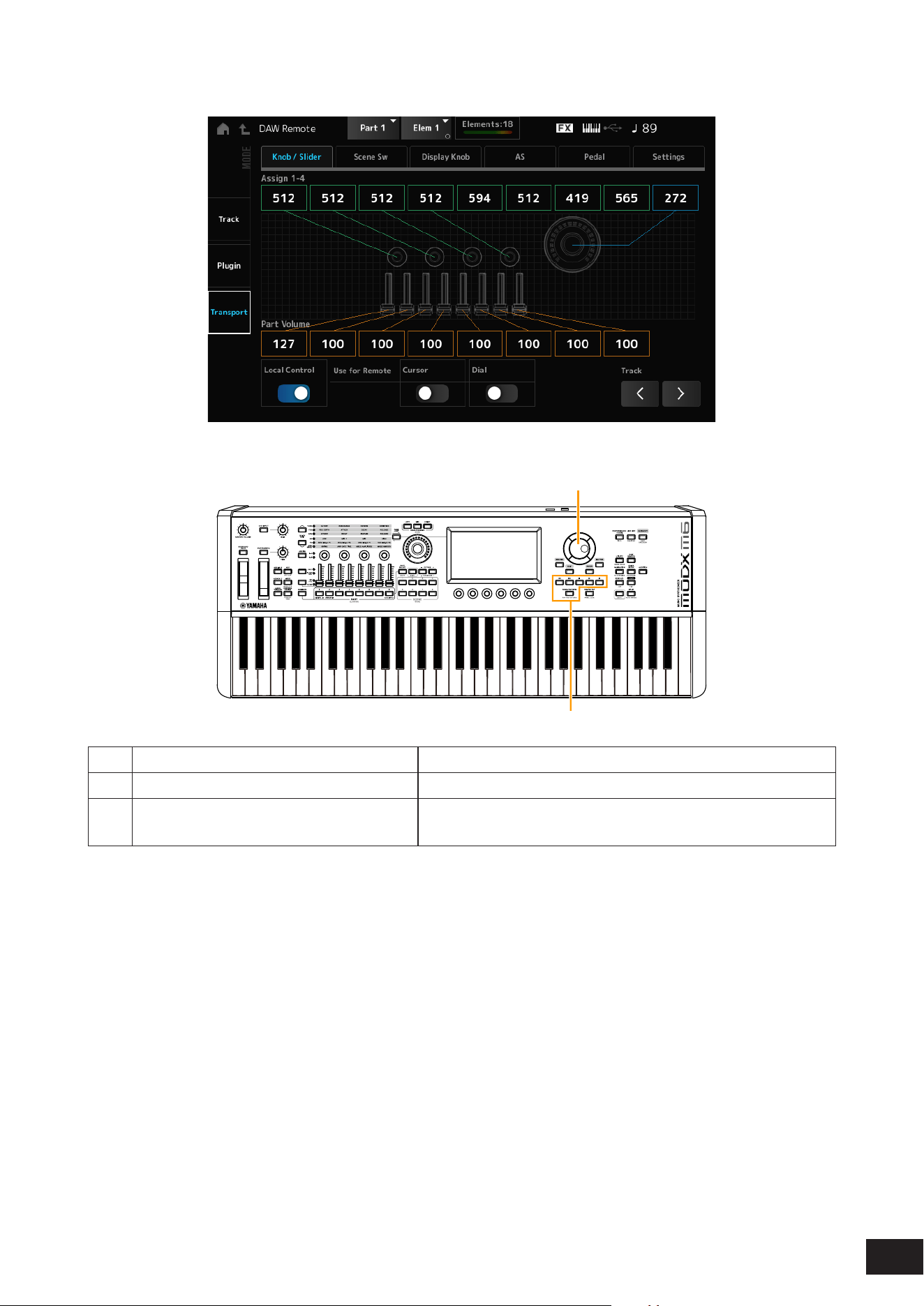
395
MODX M Operation Manual
Transport mode
Controllers
(1)
(2)
Controllers DAW operation
(1) Data dial, cursor buttons Moves the cursor position or Song position.
(2) Sequencer transport button.
[SONG/PATTERN] button
Controls the transport actions (recording and playback).
Other controllers operate as normal.

396
MODX M Operation Manual
During Edit
Edit
Sets the Control Change message, such as the control number and channel mode, that is output from Port 1.
The settings on each tab are as follows:
Common
Local (Local Control)
Sets Local Control On or Off.
This is the same as what can be set in [UTILITY]
→
Settings
→
MIDI I/O.
Use for Remote Cursor / Dial
Sets whether to use the Data dial and Cursor buttons on the Top panel for controlling the DAW.
On: For controlling the DAW.
Off: For controlling the Main display on the top panel.
Knob / Slider
CC Num. (Control Change Number)
Sets the control number for the knobs and control sliders.
Settings: 1–95
Scene SW
Scene1–8CC# (Scene 1–8 Control Number)
Sets the control number for the SCENE buttons.
Settings: 1–95
Latch/Momentary (Scene 1–8 Switch Mode)
Switches the operating mode of the SCENE buttons.
Settings: Momentary, Latch
Display Knob
DispKnob 1–6CC# (Display Knob 1–6 Control Number)
Sets the control number for the Display Knobs.
Settings: 1–95
AS
Porta Sw CC# (Portamento Switch Control Number)
Sets the control number for the [PORTAMENTO] button.
Settings: 1–95
Latch/Momentary (Portamento Switch Mode)
Switches the operating mode of the [PORTAMENTO] button.
Settings: Momentary, Latch
Porta Knob CC# (Portamento Knob Control Number)
Sets the control number for the PORTAMENTO [TIME] knob.
Settings: 1–95

397
MODX M Operation Manual
AssignSw 1 CC# (Assignable Switch 1 Control Number)
AssignSw 2 CC# (Assignable Switch 2 Control Number)
MS Trigger CC# (Motion Seq Trigger Switch Control Number)
Sets the control numbers for the [ASSIGN 1] button, [ASSIGN 2] button, and [MSEQ TRIGGER] button.
Settings: 1–95
Assign SW 1 Latch/Momentary (Assignable Switch 1 Mode)
Assign SW 2 Latch/Momentary (Assignable Switch 2 Mode)
MS Trigger Latch/Momentary (Motion Seq Trigger Switch Mode)
Switches the operating mode of the [ASSIGN 1] button, [ASSIGN 2] button, and [MSEQ TRIGGER] button.
Settings: Momentary, Latch
Pedal
FC 1 CC# (Foot Controller 1 Control Number)
FC 2 CC# (Foot Controller 2 Control Number)
Sets the control number for Foot Controller 1 and Foot Controller 2.
Settings: 1–95
FS CC# (Foot Switch Control Number)
Shows the control number for the foot switch.
Settings: 1–95
Latch/Momentary (Foot Switch Mode)
Switches the operating mode of the foot switch.
Settings: Momentary, Latch
Settings
DAW
Selects the particular DAW for use with this instrument.
Settings: Cubase, Logic Pro, Pro Tools, Live
MIDI I/O Ch.
Sets the MIDI channel for input and output of the Common and the Part with the Keyboard Control Switch to be set to On.
The MIDI channel set here is used also for sending the Control Change message from DAW Remote.
This is the same as what can be set in [UTILITY]
→
Settings
→
MIDI I/O.
Settings: Ch1–Ch16
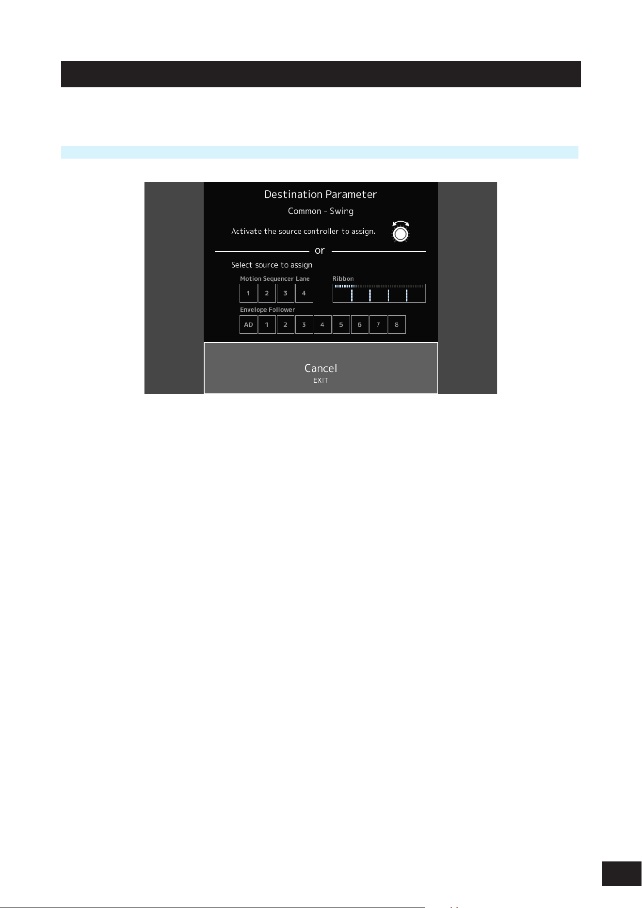
398
MODX M Operation Manual
Control Assign
Register the combination of Source and Destination in the Controller Set.
Operation
Press the [CONTROL ASSIGN] button while selecting parameters that can be assigned to the controller on the screen.
Operate the controller used to adjust the target parameter, or select Motion Sequencer Lane, Envelope Follower, or
Ribbon on the screen.
NOTE
• When you move the Super Knob but there aren’t any unused assignable knobs to proceed with the setting, an error message will
appear.
• When a Part parameter is selected, press the [COMMON] button while operating the assignable knob to select the assignable knob
for Common.
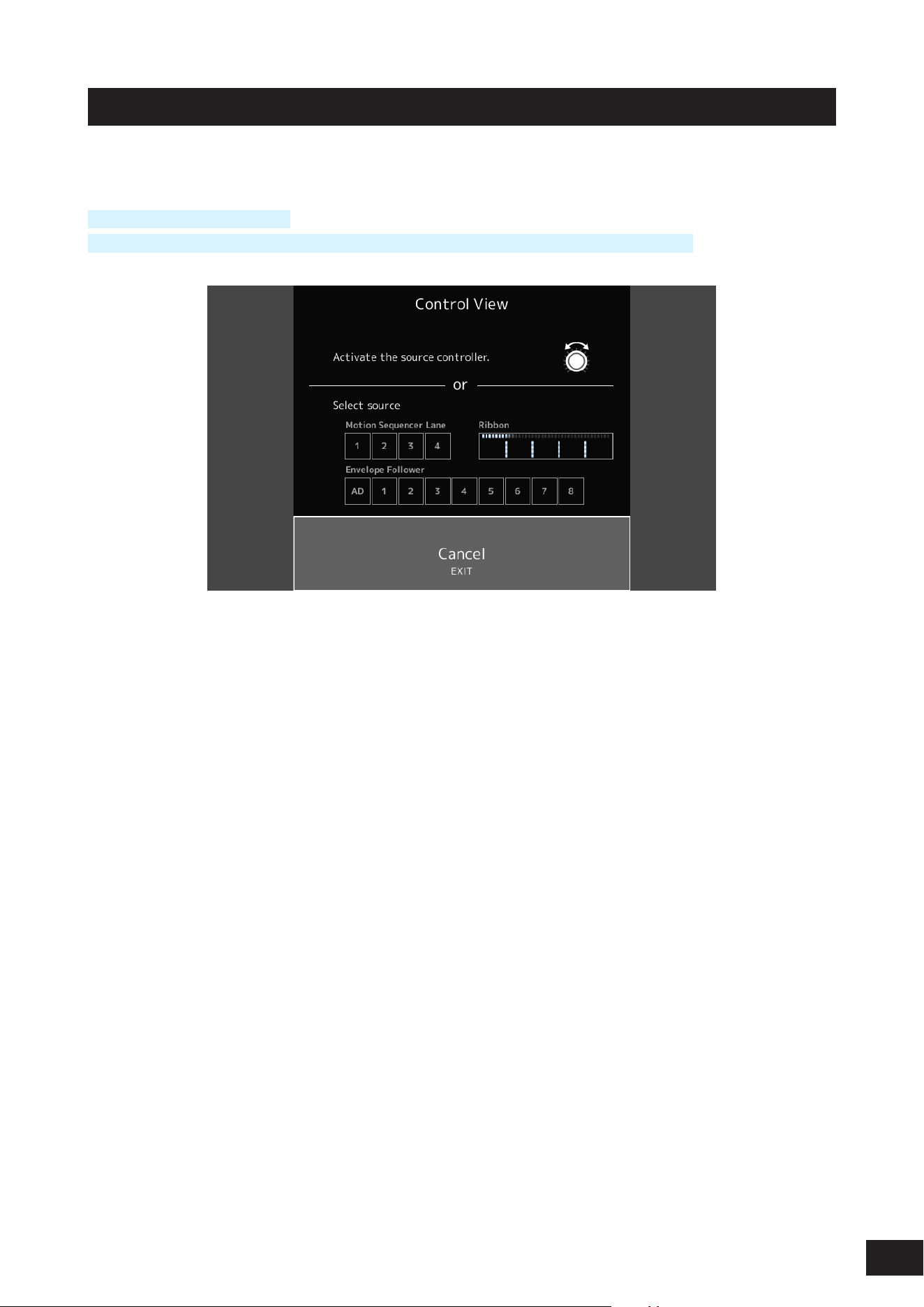
399
MODX M Operation Manual
Control View
You can check the settings of the controller being operated.
Operation
[SHIFT] + [CONTROL ASSIGN]
(With the Home screen View Mode set to Default) Tap the Control View displayed on the screen.
Operate the controller you want to check, or select Motion Sequencer Lane, Envelope Follower, or Ribbon on the screen.
The Control Assign screen will open where you can view the settings information.
400
MODX M Operation Manual
7. Other information
Effect types
No Effect Disables the Effects. Does not output the sound.
Thru Sets the Effect to Thru. The input sound is output without any effects being applied.
Reverb
HD Hall Simulates the natural acoustics of a concert hall.
REV-X Hall Hall reverb using the REV-X reverb algorithm
R3 Hall Hall reverb using the reverb algorithm of the ProR3 Digital Reverb Processor
SPX Hall Hall reverb from the classic SPX1000
HD Room Simulates the natural acoustics of a room.
REV-X Room Room reverb using the REV-X reverb algorithm
R3 Room Room reverb using the reverb algorithm of the ProR3 Digital Reverb Processor
SPX Room Room reverb from the classic SPX1000
HD Plate Simulates a plate reverb.
R3 Plate Plate reverb using the reverb algorithm of the ProR3 Digital Reverb Processor
SPX Stage Stage reverb from the classic SPX1000.
Space Simulator Allows you to specify the width, height, and depth of the room size.
Gated Reverb Produces a gated reverb.
Reverse Reverb Produces reverse playback of a gated reverb.
Shimmer Reverb Creates mystical shimmering effects by adding pitch-changed Reverb sounds.
Delay
Cross Delay The feedback of the delayed sound on each of the two channels is routed to the opposite channel.
Produces alternate delayed sounds on the right and left.
Tempo Cross Delay Tempo-synchronized Cross delay
Tempo Delay Mono Tempo-synchronized Mono delay
Tempo Delay Stereo Tempo-synchronized Stereo delay
Control Delay Delay for creating scratch sounds by changing the delay length in real-time.
Delay LR Produces two delayed sounds on the left and right, with two feedback delays.
Delay LCR Produces three delayed sounds on the left, center, and right.
Analog Delay Retro Simulates a bucket-brigade analog delay,
set to short delay.
Analog Delay Modern Simulates a bucket-brigade analog delay,
set to long delay.
401
MODX M Operation Manual
Chorus
G Chorus Creates a deep sound with complex modulation.
2 Modulator
Allows you to set the pitch modulation and amplitude modulation. Spreads out the sound naturally.
SPX Chorus Chorus effect that uses a 3-phase LFO to add modulation and spaciousness to the sound.
Symphonic Multiplexes the modulations for creating more spaciousness.
Ensemble Detune Chorus effect without modulation, created by adding a slightly pitch-shifted sound.
Flanger
VCM Flanger Flanger using VCM technology
Classic Flanger Flanger with typical swirling sounds
Tempo Flanger Flanger with tempo synchronized LFO
Dynamic Flanger Flanger that controls the delay modulation in real-time depending on the level of the input sound.
Control Flanger Allows manual operation instead of the LFO.
Phaser
VCM Phaser Mono Mono Phaser using VCM technology
VCM Phaser Stereo Stereo Phaser using VCM technology
Tempo Phaser Phaser with tempo synchronized LFO
Dynamic Phaser Effect that controls the phase in real-time depending on the level of the input sound.
Control Phaser Allows manual operation instead of the LFO.
Trem/Rtr (Tremolo & Rotary)
Auto Pan Moves the Pan left and right.
Tremolo Creates cyclical changes to the volume.
Rotary Speaker 1 Simulates a rotary speaker.
Rotary Speaker 2 Simulates a rotary speaker including an amplifier.
VCM Rotary Speaker
Classic
Standard rotary speaker effect using VCM technology. Suitable for organs.
VCM Rotary Speaker
Overdrive
Rotary speaker effect using VCM technology. Simulates the distorted sound of a rotary speaker with a
transistor preamp connected.
VCM Rotary Speaker
Studio
Rotary speaker effect using VCM technology, with three-dimensional rotation.
Dist (Distortion)
Amp Simulator 1 Simulates a guitar amplifier.
Amp Simulator 2 Simulates a guitar amplifier.
Comp Distortion Combines Compressor and Distortion.
Comp Distortion Delay Combines Compressor, Distortion, and Delay.
U.S. Combo American combo amp simulator
Jazz Combo Jazz combo amp simulator
U.S. High Gain American high gain amp simulator
British Lead British stack amp simulator
Multi FX Multi-effect processor for guitars
Small Stereo Stereo distortion for guitar sounds
British Combo British combo amp simulator
British Legend British stack amp simulator
402
MODX M Operation Manual
Comp (Compressor)
VCM Compressor 376 Compressor using VCM technology
Classic Compressor Simple, easy-to-use compressor. Suitable for solo instruments.
Multi-band Comp Splits the sound into three bands and applies compressor separately on those bands.
Uni Comp Down Compressor with a downward algorithm that suppresses loud sounds.
Uni Comp Up Compressor with an upward algorithm that amplifies soft sounds.
Parallel Comp Compressor applying parallel processing of the compressed sounds and dry sounds
Wah
VCM Auto Wah Auto Wah using VCM technology. Creates cyclical changes to the center frequency of the filter.
VCM Touch Wah Touch Wah using VCM technology. Changes the center frequency of the filter depending on the level of
the input sound.
VCM Pedal Wah Pedal Wah using VCM technology. Changes the center frequency of the filter by operating controllers,
such as a pedal.
Lo-Fi
Lo-Fi Downgrades the quality of the audio input for a lo-fi sound.
Noisy Adds noise to the sound.
Digital Turntable Adds turntable noise to the sound.
Bit Crusher Produces distortion by reducing the resolution or bandwidth of the digital sound.
Tech
Ring Modulator Changes the input to a metallic sound.
Dynamic Ring Modulator The OSC Freq parameter for the Ring Modulator is controlled in real-time depending on the level of the
input sound.
Dynamic Filter The filter cutoff frequency is controlled in real-time depending on the level of the input sound.
Auto Synth Resynthesizes the input signal using delay and modulation.
Spiralizer P Special phaser-based filter with seemingly endless up or down pitch changes.
Tempo Spiralizer P Spiralizer with tempo synchronized LFO
Spiralizer F Special flanger-based filter with seemingly endless up or down pitch changes.
Tempo Spiralizer F Spiralizer with tempo synchronized LFO
Isolator Controls the volume of each band by using a powerful filter.
Slice Slices the Amplitude EG of the input sound.
Tech Modulation Applies special modulation.
Control Filter A filter that allows manual operation of the cutoff frequency.
Vinyl Break Causes the pitch to drop gradually to create a sound effect of a turntable stopped by hand or turning the
device off.
Beat Repeat (even) Creates mechanical beats by repeatedly playing sampled sounds. The length of the repeat is specified as
a fraction of a beat with a denominator of an even number, such as 1/2, 1/4, 1/8, 1/16, and so on.
Beat Repeat (triplet) Creates mechanical beats by repeatedly playing sampled sounds. The length of the repeat is specified as
a fraction of a beat with a denominator having multiples of three, such as 1/3, 1/6, 1/12, and so on.
Beat Repeat (even+tri.) Creates mechanical beats by repeatedly playing sampled sounds.
Contains both even and triplet settings.
Beat Repeat (free) Creates mechanical beats by repeatedly playing sampled sounds. The length of the repeat is specified as
a decimal number.

403
MODX M Operation Manual
Misc
VCM EQ 501 5-band EQ using VCM technology
Presence Gives greater sonic presence to the input sound.
Harmonic Enhancer Adds harmonic overtones to make the input sound stand out.
Stereophonic Optimizer Adjusts the stereo location in the sound field.
Talking Modulator Resynthesizes the input sound to create vowel formants.
Wave Folder Controls the harmonic overtones to create a rich sound that changes over time.
VCM Mini Filter Filter that adds thickness and depth to the sound. Simulates analog synthesizer circuitry.
VCM Mini Booster Booster with distinctive characteristics. Simulates analog synthesizer circuitry.
Damper Resonance Simulates the resonance of open string notes of an acoustic piano.
Pitch Change Changes the pitch of the input sound.
Early Reflection An effect created by isolating the early reflections of the reverb.
Vocoder Extracts characteristics from the microphone sound and applies it to the Part played on the keyboard. The
instrument's sound changes to sound like a robot's voice.
NoiseGate+Comp+Eq Contains Noise Gate, Compressor, and 3-band EQ.
Suitable mainly for vocals.
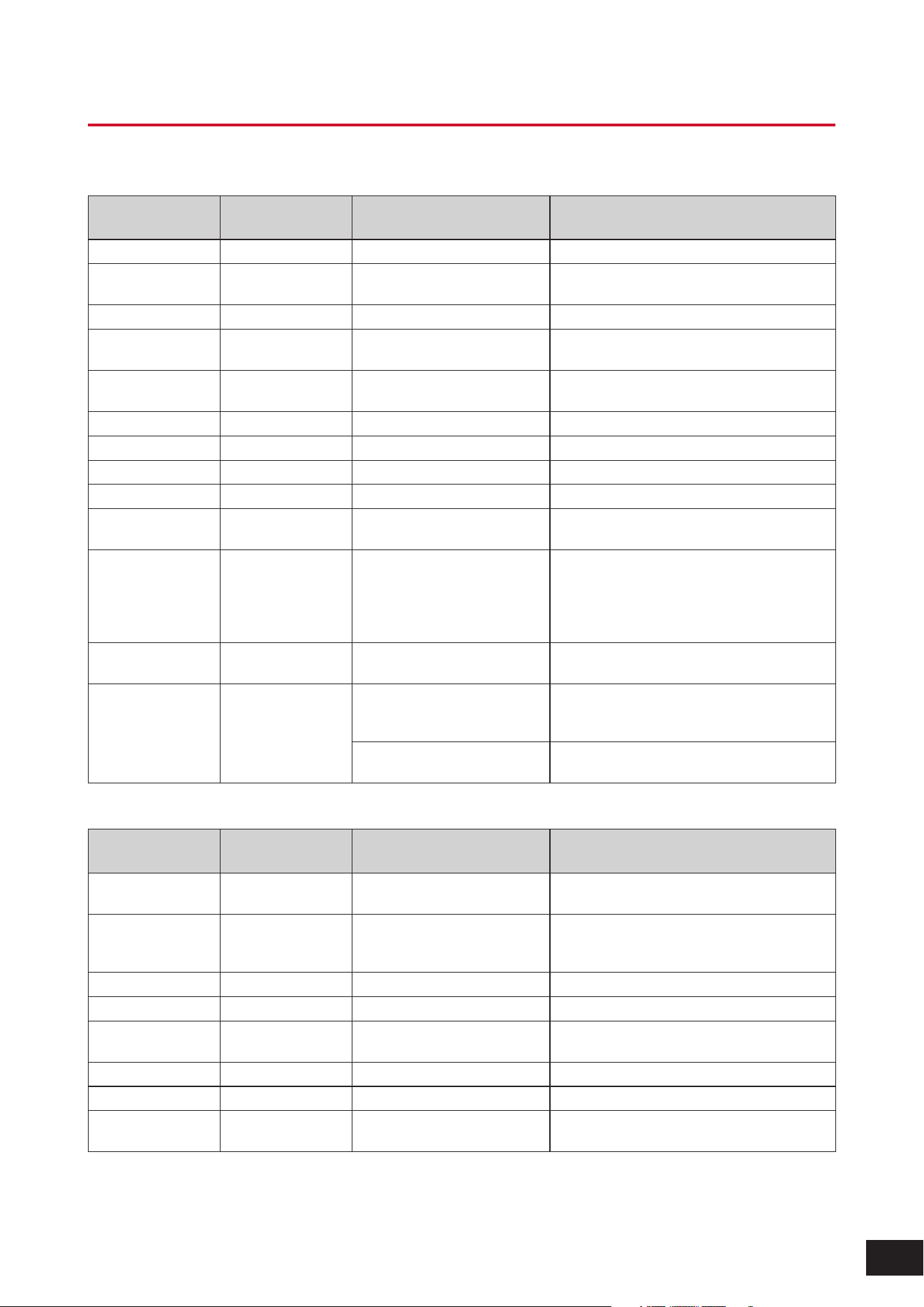
404
MODX M Operation Manual
Effect parameters
A
Display name Parameter name
Effect types using the
parameter
Description
AEG Phase AEG Phase Slice Shifts the phase of the Amplitude EG.
AM Depth AM Depth 2 Modulator, Tremolo, Noisy,
Auto Synth, Shimmer Reverb
Sets the depth of Amplitude Modulation.
AM Freq AM Frequency Shimmer Reverb Sets the Amplitude Modulation speed.
AM Inverse R AM Inverse R Auto Synth Sets the phase of the Amplitude Modulation for
the right channel.
AM LR Phase AM LR Phase Shimmer Reverb Sets the phase of the Amplitude Modulation
between the L and R channels.
AM Speed AM Speed Noisy, Auto Synth Sets the Amplitude Modulation speed.
AM Wave AM Wave Auto Synth Selects the wave for modulating the Amplitude.
AM Waveform AM Waveforms Shimmer Reverb Selects the wave for modulating the Amplitude.
Amp Type Amp Type Amp Simulator 2 Selects the amplifier type to be simulated.
Analog Feel Analog Feel Classic Flanger Adds the characteristics of an analog flanger to
the sound.
Attack Attack Comp Distortion, VCM
Compressor 376, Classic
Compressor, Downward
Compressor, Upward
Compressor
Sets the length of time it takes for the compressor
to reach the maximum.
Attack Offset Attack Offset VCM Touch Wah Sets the length of time it takes for the Wah effect
to be applied.
Attack Time Attack Time Dynamic Flanger, Dynamic
Phaser, Dynamic Ring Modulator,
Dynamic Filter
Sets the attack time of the Envelope Follower.
Beat Repeat Sets the Attack time of the Gate applied to the
entire sound
B
Display name Parameter name
Effect types using the
parameter
Description
Balance Balance U.S. Combo Adjusts the balance between the bass and the
treble.
Bass Bass British Combo, British Lead,
British Legend, Jazz Combo,
U.S. High Gain
Adjusts the tone quality of the bass.
Bit Bit Bit Crusher Reduces the bit precision.
Bit Assign Bit Assign Lo-Fi Sets how Word Length is applied to the sound
Bit Link Bit Link Bit Crusher Sets the level of the Side setting that follows the
Mid value when M/S is on
BPF 1–10 Gain BPF1–10 Gain Vocoder Sets the Gain of BPFs 1–10 of the Vocoder effect
Break Break Vinyl Break Sets Break to On
Brilliant Brilliant British Combo Adjusts the volume of the sound for which the
bass is cut.
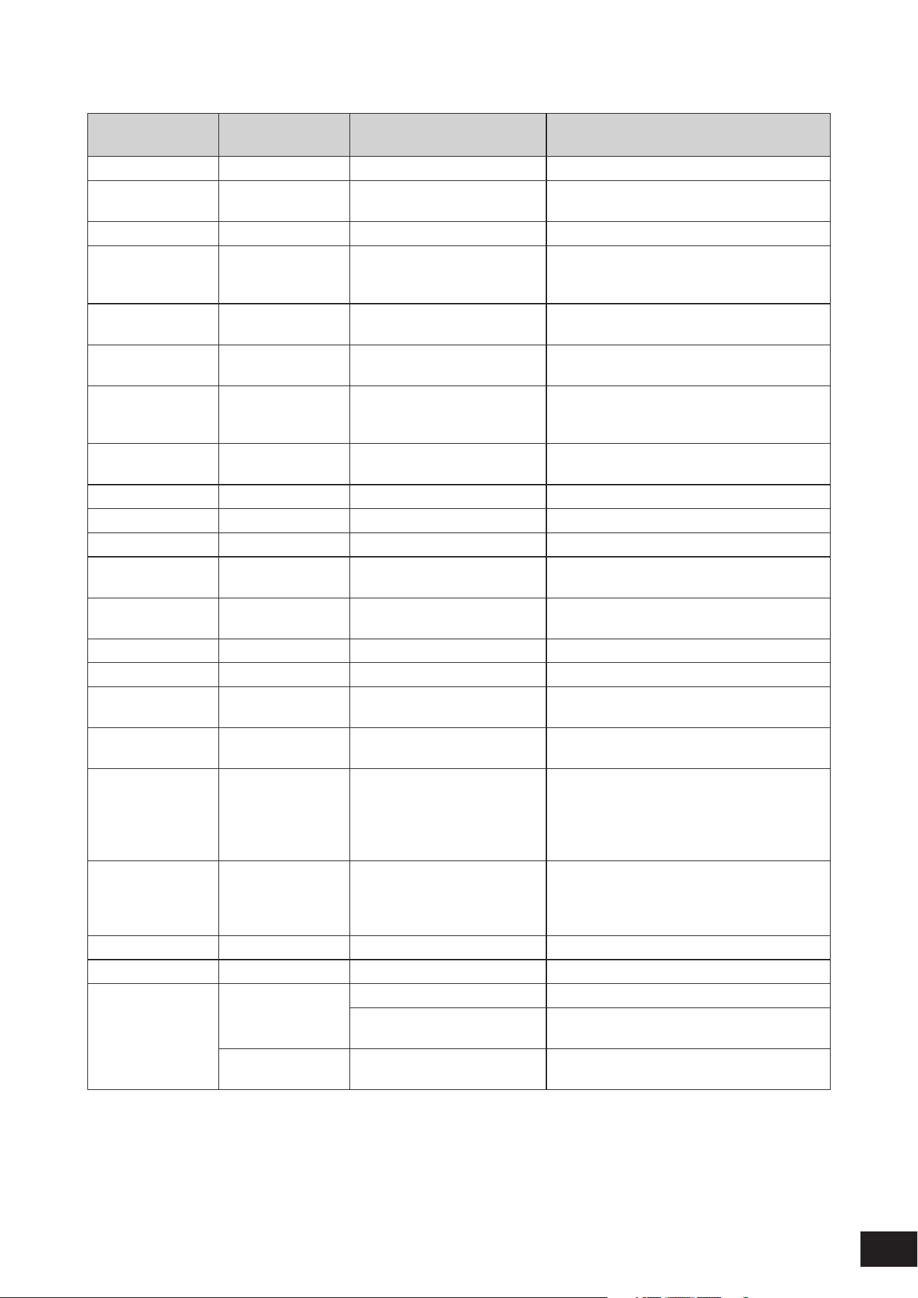
405
MODX M Operation Manual
C
Display name Parameter name
Effect types using the
parameter
Description
Chorus Chorus Jazz Combo Selects the Chorus type.
Click Density Click Density Digital Turntable Sets the frequency of the click sound to be
repeated.
Click Level Click Level Digital Turntable Sets the click level.
Clipper Clipper Upward Compressor, Downward
Compressor
Sets the distortion level of the Clipper that
determines the maximum level for limiting the
wave.
Clipper Source Clipper Source Upward Compressor, Downward
Compressor
Selects the signal to which the Clipper effect is
applied.
Color Color Control Phaser, VCM Phaser
Mono, VCM Phaser Stereo
Sets the fixed phase modulation.
Com Release Common Release Multi Band Comp Sets the Release Time (the time it takes for the
Compressor effect to fade away) used commonly
on three bands.
Comp Attack Comp Attack NoiseGate+Comp+Eq Sets the length of time for the Compressor to be
applied.
Comp Level Comp Level Small Stereo Adjusts the output level of the compressor.
Comp Out Lvl Comp Output Level NoiseGate+Comp+Eq Sets the output level of the compressor.
Comp Ratio Comp Ratio NoiseGate+Comp+Eq Sets the ratio of the compressor.
Comp Release Comp Release NoiseGate+Comp+Eq Sets the length of time it takes until the
compressor effect fades away.
Comp Sustain Comp Sustain Multi FX, Small Stereo Adjusts the length of time for the compressor to
sustain.
Comp Sw Comp SW Small Stereo Turns the compressor on or off.
Comp Threshold Comp Threshold NoiseGate+Comp+Eq Sets the input level for the effect to be applied.
Compress Compress Comp Distortion Delay Sets the threshold (or the minimum input level) for
the compressor to be applied.
Compression Compression Parallel Compressor Sets the extent to which the compressor is
applied.
Control Type Control Type Control Delay When set to Normal, the delay effect is always
applied to the sound. When set to Scratch, the
delay effect is not applied if the controller value 0
is set to the Delay Time. The delay is applied to
other cases.
Cross-Feedback Cross-Feedback Shimmer Reverb Sets the balance of the pitch-shifted sound on the
first routing and the pitched sound on the second
routing to be sent to the opposite routing for the
feedback of the pitch-shifted sound
Crush Type Crush Type Bit Crusher Sets how the bit precision is reduced.
Cut Cut British Combo Sets the velocity curve to the end of the sound
Cutoff Cutoff Frequency Beat Repeat Cuts the high frequencies.
VCM Mini Filter Sets the Cutoff Frequency of the Filter for the
effect sound.
Cutoff Frequency
Control
Control Filter Sets the Filter Cutoff Frequency.
406
MODX M Operation Manual
D
Display name Parameter name
Effect types using the
parameter
Description
Damper Control Damper Control Damper Resonance Sets the amount of resonance for the piano
damper.
Decay Decay REV-X Hall, REV-X Room Controls how the reverb sound decays.
Delay Control Delay Control Multi FX Adjusts the depth or amount of the effect set to
Delay Sw
Delay Input Lvl Delay Input Level Analog Delay Retro, Analog
Delay Modern
Sets the input level to the delay.
Delay Level Delay Level Auto Synth Sets the level of the delayed sound.
Delay Level C Delay Level C Delay LCR Sets the level of the delayed sound for the center
channel.
Delay Mix Delay Mix Comp Distortion Delay Sets the mixing level of the delayed sound.
Delay Offset Delay Offset G Chorus, 2 Modulator, SPX
Chorus, Symphonic, Classic
Flanger, Tempo Flanger,
Dynamic Flanger
Sets the offset value for the delay modulation.
Delay Sw Delay SW Multi FX Sets the delay type or modulation type.
Delay Time Delay Time Tempo Delay Mono, Tempo
Delay Stereo
Specifies the delay length in note duration.
Comp Ratio Comp Ratio Control Delay, Auto Synth, Tech
Modulation, Multi FX, Analog
Delay Retro, Analog Delay
Modern
Sets the delay length.
Delay Time C Delay Time C Delay LCR Sets the delay length for the center channel.
Delay Time L Delay Time L Delay LR, Delay LCR, Comp
Distortion Delay
Sets the delay length for the left channel.
Delay Time L>R Delay Time L>R Cross Delay, Tempo Cross Delay Sets the delay time for the sound that is input
from the left to be output from the right.
Delay Time R Delay Time R Delay LR, Delay LCR, Comp
Distortion Delay
Sets the delay length for the right channel.
Delay Time R>L Delay Time R>L Cross Delay, Tempo Cross Delay Sets the delay time for the sound that is input
from the right to be output from the left.
Delay Tm Ofs R Delay Time Offset R Auto Synth, Tech Modulation Sets the offset to the delay length for the right
channel.
Density Density R3 Hall, R3 Room, R3 Plate, SPX
Hall, SPX Room, SPX Stage,
Space Simulator
Sets the density of the reverb.
Early Reflection, Gated Reverb,
Reverse Reverb
Sets the density of the reflections.
Depth Depth Space Simulator Sets the depth of the simulated room.
VCM Flanger Sets the Amplitude of the LFO wave that controls
the cyclic change of the delay modulation.
VCM Phaser Mono, VCM Phaser
Stereo
Sets the Amplitude value of the LFO wave
that controls the cyclic change of the phase
modulation.
Jazz Combo Sets the depth of the Chorus/Vibrato.
Device Device Amp Simulator 1, Comp
Distortion Delay
Sets the device for creating distortion sounds
407
MODX M Operation Manual
Display name Parameter name
Effect types using the
parameter
Description
Diffusion Diffusion REV-X Hall, REV-X Room, R3
Hall, R3 Room, R3 Plate, SPX
Hall, SPX Room, SPX Stage,
Space Simulator, Gated Reverb,
Reverse Reverb, Shimmer
Reverb
Sets the spread of the reverb.
Tempo Phaser, Early Reflection Sets the spread of the selected effect.
Direction Direction Dynamic Flanger, Dynamic
Phaser, VCM Touch Wah, VCN
Pedal Wah, Dynamic Ring
Modulator, Dynamic Filter
Sets the direction of the modulation controlled by
the envelope follower.
Tempo Spiralizer P, Tempo
Spiralizer F
Sets the direction of the pitch shift.
Dist Drive Dist Drive Multi FX, Small Stereo Controls the amount of distortion.
Dist EQ Dist EQ Multi FX, Small Stereo Switches the EQ type for adjusting the tone
quality of distortion.
Dist Presence Dist Presence Multi FX, Small Stereo Adjusts the tone quality for each distortion type.
Dist Sw Dist SW Multi FX Sets the distortion type.
Dist Tone Dist Tone Multi FX, Small Stereo Adjusts the tone quality of distortion.
Dist Type Dist Type Small Stereo Sets the distortion type.
Distortion Distortion Jazz Combo Sets the level of distortion.
Divide Freq Hi Divide Freq High Multi Band Comp Sets the Mid/High frequency to divide into three
bands
Divide Freq Low Divide Freq Low Multi Band Comp Sets the Low/Mid frequency to divide into three
bands
Divide Min Lvl Divide Min Level Slice Sets the minimum level of the sliced section.
Divide Type Divide Type Slice Specifies the timing for slicing by note duration.
Drive Drive Noisy, Slice, Rotary Speaker 2,
VCM Rotary Speaker Classic,
VCM Rotary Speaker Overdrive,
VCM Rotary Speaker Studio
Sets the level of distortion.
Harmonic Enhancer, Talking
Modulator
Sets the level of the effect.
Drive Horn Drive Horn Rotary Speaker 1 Sets the depth of modulation generated by the
rotation of the horn (treble).
Drive Rotor Drive Rotor Rotary Speaker 1 Sets the depth of modulation generated by the
rotation of the rotor (woofer).
Dry Level Dry Level Digital Turntable Sets the level of the dry sound.
Dry LPF Cutoff Dry LPF Cutoff
Frequency
Digital Turntable Sets the frequency to cut by using the Low-Pass
Filter applied to the dry sound.
Dry Mix Level Dry Mix Level Auto Synth Sets the level of the dry sound.
Dry/Wet Dry/Wet Balance All Sets the balance of the dry sound and the effect
sound.
408
MODX M Operation Manual
E
Display name Parameter name
Effect types using the
parameter
Description
Edge Edge Comp Distortion Sets the curve that determines how the
sound is distorted.
Emphasis Emphasis Lo-Fi Sets the change of the high frequency
characteristics.
EQ 1 Freq EQ1(LSH) Frequency VCM EQ 501 Sets the cutoff frequency of EQ1 (Low
Shelving)
EQ 1 Gain EQ1(LSH) Gain VCM EQ 501 Sets the gain of EQ1 (Low Shelving)
EQ 2 Freq EQ2 Frequency VCM EQ 501 Sets the center frequency of EQ2.
EQ 2 Gain EQ2 Gain VCM EQ 501 Sets the gain of EQ2.
EQ 2 Q EQ2 Q VCM EQ 501 Sets the Q of EQ2.
EQ 3 Freq EQ3 Frequency VCM EQ 501 Sets the center frequency of EQ3
EQ 3 Gain EQ3 Gain VCM EQ 501 Sets the gain of EQ3
EQ 3 Q EQ3 Q VCM EQ 501 Sets the Q of EQ3
EQ 4 Freq EQ4 Frequency VCM EQ 501 Sets the center frequency of EQ4
EQ 4 Gain EQ4 Gain VCM EQ 501 Sets the gain of EQ4
EQ 4 Q EQ4 Q VCM EQ 501 Sets the Q of EQ4
EQ 5 Freq EQ5(HSH) Frequency VCM EQ 501 Sets the cutoff frequency of EQ5 (High
Shelving)
EQ 5 Gain EQ5(HSH) Gain VCM EQ 501 Sets the gain of EQ5 (High Shelving)
EQ Frequency EQ Frequency Noisy Sets the frequency to boost or attenuate by
using the EQ.
VCM Mini Booster Sets the frequency of the EQ set to Type
EQ Gain EQ Gain Noisy Sets the gain to boost or attenuate by using
the EQ.
EQ High Freq EQ High Frequency Cross Delay, Tempo Cross Delay,
Tempo Delay Mono, Tempo
Delay Stereo, Control Delay,
Delay LR, Delay LCR, G Chorus,
2 Modulator, SPX Chorus,
Symphonic, Ensemble Detune,
Classic Flanger, Tempo Flanger,
Dynamic Flanger, Tempo Phaser,
Dynamic Phaser, Auto Pan,
Tremolo, Rotary Speaker 1,
Ring Modulator, Dynamic Ring
Modulator, Dynamic Filter, Slice,
HD Hall, HD Room, HD Plate,
NoiseGate+Comp+Eq
Sets the frequency of the high band to boost
or attenuate by using the EQ.
EQ High Gain EQ High Gain Cross Delay, Tempo Cross Delay,
Tempo Delay Mono, Tempo
Delay Stereo, Control Delay,
Delay LR, Delay LCR, G Chorus,
2 Modulator, SPX, Chorus,
Symphonic, Ensemble Detune,
Classic Flanger, Tempo Flanger,
Dynamic Flanger, Tempo Phaser,
Dynamic Phaser, Auto Pan,
Tremolo, Rotary Speaker 1,
Ring Modulator, Dynamic Ring
Modulator, Dynamic Filter, Slice,
HD Hall, HD Room, HD Plate,
NoiseGate+Comp+Eq
Sets the gain of the high band to boost or
attenuate by using the EQ.

409
MODX M Operation Manual
Display name Parameter name
Effect types using the
parameter
Description
EQ Low Freq EQ Low Frequency Cross Delay, Tempo Cross Delay,
Tempo Delay Mono, Tempo
Delay Stereo, Control Delay,
Delay LR, Delay LCR, G Chorus,
2 Modulator, SPX Chorus,
Symphonic, Ensemble Detune,
Classic Flanger, Tempo Flanger,
Dynamic Flanger, Tempo Phaser,
Dynamic Phaser, Auto Pan,
Tremolo, Rotary Speaker 1,
Ring Modulator, Dynamic Ring
Modulator, Dynamic Filter, Slice,
Comp Distortion, HD Hall, HD
Room, HD Plate
Sets the frequency of the low band to boost or
attenuate by using the EQ.
EQ Low Gain EQ Low Gain Cross Delay, Tempo Cross Delay,
Tempo Delay Mono, Tempo
Delay Stereo, Control Delay,
Delay LR, Delay LCR, G Chorus,
2 Modulator, SPX Chorus,
Symphonic, Ensemble Detune,
Classic Flanger, Tempo Flanger,
Dynamic Flanger, Tempo Phaser,
Dynamic Phaser, Auto Pan,
Tremolo, Rotary Speaker 1,
Ring Modulator, Dynamic Ring
Modulator, Dynamic Filter, Slice,
Comp Distortion, HD Hall, HD
Room, HD Plate
Sets the gain of the low band to boost or
attenuate by using the EQ.
EQ Mid Freq EQ Mid Frequency G Chorus, 2 Modulator, SPX
Chorus, Symphonic, Classic
Flanger, Tempo Flanger, Auto
Pan, Tremolo, Comp Distortion,
NoiseGate+Comp+EQ
Sets the frequency of the mid band to boost
or attenuate by using the EQ.
EQ Mid Gain EQ Mid Gain G Chorus, 2 Modulator, SPX
Chorus, Symphonic, Classic
Flanger, Tempo Flanger, Auto
Pan, Tremolo, Comp Distortion,
NoiseGate+Comp+EQ
Sets the gain of the mid band to boost or
attenuate by using the EQ.
EQ Mid Width EQ Mid Width G Chorus, 2 Modulator, SPX
Chorus, Symphonic, Classic
Flanger, Tempo Flanger, Auto
Pan, Tremolo, Comp Distortion,
NoiseGate+Comp+EQ
Sets the width of the middle band to boost or
attenuate by using the EQ.
EQ Width EQ Width Noisy Sets the width to boost or attenuate by using
the EQ.
ER/Rev Balance ER/Rev Balance R3 Hall, R3 Room, R3 Plate, SPX
Hall, SPX Room, SPX Stage,
Space Simulator
Sets the level balance of the early reflection
and reverb sounds.
410
MODX M Operation Manual
F
Display name Parameter name
Effect types using the
parameter
Description
F/R Depth F/R Depth Auto Pan Sets the depth of the pan on the front and rear
(available when PAN Direction is set to L Turn
or R Turn)
FB Hi Dmp Ofs R FB Hi Damp Offset R Tech Modulation Sets the offset for the treble attenuation on
the right channel
FB High Damp Feedback High Damp R3 Hall, R3 Room, R3 Plate,
SPX Hall, SPX Room, SPX
Stage, Space Simulator, Cross
Delay, Tempo Cross Delay,
Tempo Delay Mono, Tempo
Delay Stereo, Control Delay,
Delay LR, Delay LCR, Classic
Flanger, Early Reflection,
Gated Reverb, Reverse Reverb,
Comp Distortion Delay, Tech
Modulation
Adjusts the attenuation of high frequency
sound by using the feedback sound. The
smaller the value, the faster the attenuation of
the high frequency sounds.
FB Level Ofs R FB Level Offset R Auto Synth, Tech Modulation Sets the offset for the amount of feedback on
the right channel
FB Time L Feedback Time L Delay LR Sets the length of feedback for left delay
FB Time R Feedback Time R Delay LR Sets the length of feedback for right delay
Feedback Feedback VCM Flanger, VCM Phaser
Mono, VCM Phaser Stereo,
Control Flanger, Control Phaser
Spiralizer P, Spiralizer F, Tempo
Spiralizer P, Tempo Spiralizer F
Sets the level of the output signal returned to
the effect block.
Feedback Feedback Level R3 Hall, R3 Room, R3 Plate,
SPX Hall, SPX Room, SPX
Stage, Space Simulator, Early
Reflection, Gated Reverb,
Reverse Reverb
Sets the feedback level of the initial delay.
Cross Delay, Tempo Cross
Delay, Tempo Delay Mono,
Tempo Delay Stereo, Control
Delay, Delay LR, Delay LCR,
G Chorus, 2 Modulator, SPX
Chorus, Classic Flanger, Tempo
Flanger, Dynamic Flanger, Comp
Distortion Delay, Auto Synth,
Teck Modulation
Sets the level of the delay sound to be sent
back to the input (phase is inverted for
negative values)
Analog Delay Retro, Analog
Delay Modern
Sets the feedback level of the delayed sound.
Tempo Phaser, Dynamic Phaser Sets the level of the signal output from the
phaser and returned to the input (phase is
inverted for negative values)
Feedback Lvl 1 Feedback Level 1 Pitch Change Sets the feedback level of the delayed sound
on the first routing
Feedback Lvl 2 Feedback Level 2 Pitch Change Sets the feedback level of the delayed sound
on the second routing
Feedback Time Feedback Time Delay LCR, Comp Distortion
Delay
Sets the delay length of the feedback.
Filter Type Filter Type Lo-Fi Selects the effect type.
Dynamic Filter, Control Filter Sets the filter Type.
Beat Repeat Sets the filter type for the effect sound.
Fine 1 Fine 1 Pitch Change, Shimmer Reverb Fine-tunes the pitch on the first routing.
411
MODX M Operation Manual
Display name Parameter name
Effect types using the
parameter
Description
Fine 2 Fine 2 Pitch Change, Shimmer Reverb Fine-tunes the pitch on the second routing.
Flanger Control Flanger Control Control Flanger Sets the delay value (the value of the Comb
Filter of the delay modulation)
Fold Fold Wave Folder Distorts the sound.
Fold Type Fol d Type Wave Folder Selects the level of distortion.
Formant Offset Formant Offset Vocoder Adds the offset value to the Cutoff Frequency
of the BPF for the input of the instrument
sound.
Formant Shift Formant Shift Vocoder Shifts the Cutoff Frequency of each BPF for
the input of the instrument sound.
Freeze Freeze Beat Repeat When this parameter is set to On, the beat is
repeated.
G
Display name Parameter name
Effect types using the
parameter
Description
Gain Gain U.S. High Gain Sets the gain of the preamplifier.
VCM Mini Booster Adjusts the Gain of the ShelfEQ
Gain Boost Gain Boost U.S. Combo Switches the gain of the power amplifier.
Gain Limit Gain Limit Upward Compressor Sets the maximum Gain level
Gate Time Gate Time Slice Sets the gate time of a slice.
Beat Repeat Sets the Gate time of the entire sound
H
Display name Parameter name
Effect types using the
parameter
Description
Height Height Space Simulator Sets the height of the simulated room.
Hi Damp Freq High Damp Frequency HD Hall, HD Room, HD Plate Adjusts the attenuation of the high band.
High Attack High Attack Multi Band Comp Sets the length of time for the compressor to
be applied to the high band
High Cut High Cut U.S. Combo Cuts the high band.
High Gain High Gain Multi Band Comp Sets the output level for the high band
High Gain L High Subband Gain Lch Stereophonic Optimizer Sets the resultant gain of the High band
after the adjustment of the stereo sound (L
channel)
High Gain R High Subband Gain Rch Stereophonic Optimizer Sets the resultant gain of the High band
after the adjustment of the stereo sound (R
channel)
High Level High Level Isolator Sets the level of the high band.
High Mute High Mute Isolator Switches the mute for the high band.
High Ratio High Ratio REV-X Hall, REV-X Room, HD
Hall, HD Room, HD Plate
Adjusts the ratio of the high frequencies.
Multi Band Comp Sets the compression ratio for the high band
High Threshold High Threshold Multi Band Comp Sets the minimum input level for the effect to
be applied to the high band
High Treble High Treble Jazz Combo Adjusts the tone quality in the frequency
higher than the Treble setting
412
MODX M Operation Manual
Display name Parameter name
Effect types using the
parameter
Description
Horn Accel Horn Acceleration Rotary Speaker 2, VCM Rotary
Speaker Classic, VCM Rotary
Speaker Overdrive, VCM Rotary
Speaker Studio
Sets how the rotation of the horn (treble)
changes from Slow to Fast
Horn Decel Horn Deceleration Rotary Speaker 2, VCM Rotary
Speaker Classic, VCM Rotary
Speaker Overdrive, VCM Rotary
Speaker Studio
Sets how the rotation of the horn (treble)
changes from Fast to Slow
Horn Fast Horn Speed Fast Rotary Speaker 1, Rotary
Speaker 2, VCM Rotary Speaker
Classic, VCM Rotary Speaker
Overdrive, VCM Rotary Speaker
Studio
Sets the rotation speed of the horn (treble) for
the Fast setting
Horn Level Horn Level VCM Rotary Speaker Classic,
VCM Rotary Speaker Overdrive,
VCM Rotary Speaker Studio
Sets the volume of the horn (treble).
Horn Slow Horn Speed Slow Rotary Speaker 1, Rotary
Speaker 2, VCM Rotary Speaker
Classic, VCM Rotary Speaker
Overdrive, VCM Rotary Speaker
Studio
Sets the rotation speed of the horn (treble) for
the Slow setting
Horn Slow/Fast Horn Slow/Fast Time Rotary Speaker 1 Sets the transition time for the rotation speed
of the horn (treble) to change from Slow to
Fast
HPF Cutoff HPF Cutoff Frequency REV-X Hall, REV-X Room,
R3 Hall, R3 Room, R3 Plate,
SPX Hall, SPX Room, SPX
Stage, Space Simulator, Ring
Modulator, Dynamic Ring
Modulator, Auto Synth, Harmonic
Enhancer, Early Reflection,
Gated Reverb, Reverse Reverb
Sets the low frequency to cut by using the
HPF
Vocoder Sets the Cutoff Frequency of the High-Pass
Filter applied to the sound input from the
microphone.
HPF Output Lvl HPF Output Level Vocoder Sets how much the output from High-Pass
Filter is mixed with the output from the
Vocoder.
413
MODX M Operation Manual
I
Display name Parameter name
Effect types using the
parameter
Description
Initial Delay Initial Delay REV-X Hall, REV-X Room,
R3 Hall, R3 Room, R3 Plate,
SPX Hall, SPX Room, SPX
Stage, Space Simulator, Early
Reflection, HD Hall, HD Room,
HD Plate, Gated Reverb,
Reverse Reverb
Sets the delay time for the early reflections.
Initial Delay 1 Initial Delay 1 Pitch Change Sets the delay length of the first series of
effects.
Initial Delay 2 Initial Delay 2 Pitch Change Sets the delay length of the second series of
effects.
Initial Delay L Initial Delay Lch Ensemble Detune Sets the length of the left channel delay.
Initial Delay R Initial Delay Rch Ensemble Detune Sets the length of the right channel delay.
Input Level Input Level Bit Crusher, VCM Compressor
376, Rotary Speaker 2, Parallel
Compressor, Wave Folder, VCM
Mini Filter, VCM Mini Booster
Sets the input level.
Input Mode Input Mode G Chorus, 2 Modulator, SPX
Chorus, Auto Pan, Tremolo, Lo-Fi
Selects whether the input sound is in mono or
stereo.
Input Select Input Select Cross Delay, Tempo Cross Delay Selects an input.
Inst Level Inst Level Vocoder Sets the input level of the Instrument sound.
K
Display name Parameter name
Effect types using the
parameter
Description
Knee Knee Upward Compressor, Downward
Compressor
Sets the curve around the Threshold. The
higher the value, the shallower the curve.
L
Display name Parameter name
Effect types using the
parameter
Description
L/R Depth L/R Depth Auto Pan Sets the depth of the left and right pan.
L/R Diffusion L/R Diffusion Tempo Delay Mono, Tempo
Delay Stereo
Sets the difference of the delay on the right
and left for creating spaciousness.
Lag Lag Tempo Cross Delay, Tempo
Delay Mono, Tempo Delay
Stereo
Sets an additional delay length applied to the
delayed sound specified by a note duration.
Length Length Beat Repeat Sets the length for a repeat.
Level Offset Dyna Level Offset Dynamic Flanger, Dynamic
Phaser, Dynamic Ring Modulator,
Dynamic Filter
Sets the offset value added to the output of
the envelope follower.
LFO Depth LFO Depth SPX Chorus, Symphonic, Classic
Flanger, Tempo Flanger, Ring
Modulator
Sets the depth of the modulation.
Tempo Phaser Sets the depth of the phase modulation.
Wave Folder Adjusts the depth of the LFO effect.
LFO Shape LFO Shape Wave Folder Adjusts the shape of the LFO.

414
MODX M Operation Manual
Display name Parameter name
Effect types using the
parameter
Description
LFO Speed LFO Speed G Chorus, 2 Modulator, SPX
Chorus, Symphonic, Classic
Flanger, Tremolo, Ring
Modulator, Multi FX
Sets the frequency of the modulation.
Tempo Flanger, Tempo Phaser Specifies the modulation speed by note
duration.
Auto Pan Sets the frequency of the Auto Pan.
Wave Folder Adjusts the LFO speed.
LFO Wave LFO Wave Classic Flanger, Ring Modulator Selects the wave for modulation.
Auto Pan Sets the panning curve.
VCM Auto Wah Selects the wave: sine or square.
Liveness Liveness Gated Reverb, Reverse Reverb,
Early Reflection
Sets the attenuation of the early reflections.
Ln Chg Quantz Length Change Quantize Beat Repeat Quantizes the timing for changing the Length
parameter.
Low Attack Low Attack Multi Band Comp Sets the length of time for the compressor to
be applied to the low band
Low Cut Low Cut U.S. Combo Cuts the low band.
Low Gain Low Gain Multi Band Comp Sets the output level for the low band
Low Gain L Low Subband Gain Lch Stereophonic Optimizer Sets the resultant gain of the Low band
after the adjustment of the stereo sound (L
channel)
Low Gain R Low Subband Gain Rch Stereophonic Optimizer Sets the resultant gain of the Low band
after the adjustment of the stereo sound (R
channel)
Low Level Low Level Isolator Sets the level for the low band.
Low Mute Low Mute Isolator Switches the mute for the low band.
Low Ratio Low Ratio REV-X Hall, REV-X Room Sets the adjustment of the low frequencies.
Multi Band Comp Sets the compression ratio for the low band
Low Threshold Low Threshold Multi Band Comp Sets the minimum input level for the effect to
be applied to the low band
Lower Range Lower Range VCM Auto Wah, VCM Touch
Wah, VCM Pedal Wah
Sets the maximum value for the variable
range of the Wah filter.
Control Flanger Sets the maximum value for the variable
range of the Flanger Control
Control Phaser Sets the maximum value for the variable
range of the Phase Control
LPF Cutoff LPF Cutoff Frequency REV-X Hall, REV-X Room,
R3 Hall, R3 Room, R3 Plate,
SPX Hall, SPX Room, SPX
Stage, Space Simulator, Amp
Simulator 2, Comp Distortion,
Noisy, Ring Modulator, Dynamic
Ring Modulator, Auto Synth,
Early Reflection, Gated Reverb,
Reverse Reverb, Auto Synth,
Noisy
Sets the high frequency range cut by the
Low-Pass Filter.
LPF Resonance LPF Resonance Noisy Adds characteristics to the input to the Low-
Pass Filter.

415
MODX M Operation Manual
M
Display name Parameter name
Effect types using the
parameter
Description
M/S M/S Bit Crusher When this parameter is on, each sound
located at the center, left, and right changes
individually.
Make Up Gain Make Up Gain Upward Compressor, Downward
Compressor
Adjusts the level of the signal output from the
compressor.
Manual Manual VCM Flanger Sets the offset value of the delay modulation.
VCM Phaser Mono, VCM Phaser
Stereo
Sets the offset value of the phase
modulation.
Master Volume Master Volume U.S. High Gain, British Lead,
British Legend
Adjusts the gain of the power amplifier.
Mic Input Level Mic Input Level Vocoder Sets the input level of the microphone
Mic L-R Angle Mic L-R Angle Rotary Speaker 1, Rotary
Speaker 2, VCM Rotary Speaker
Classic, VCM Rotary Speaker
Overdrive, VCM Rotary Speaker
Studio
Sets the L/R angle of the microphone for
extracting sound from the output
Mic Out Gate Mic Output Gate Switch Vocoder Off: Always passes HPF output and Noise
Generator output
On: Passes HPF output and Noise Generator
output when there is audio input of the
Instrument sound
Mic Position Mic Position U.S. Combo, Jazz Combo, U.S.
High Gain, British Lead, British
Combo, British Legend, Rotary
Speaker 2
Sets the relative position of the microphone
to the speaker.
Mid Middle British Lead, British Legend,
Jazz Combo, U.S. High Gain
Sets the tone quality of the mid band.
Mid 1 Gain L Mid1 Subband Gain Lch Stereophonic Optimizer Sets the resultant gain of the Mid1 band
after the adjustment of the stereo sound (L
channel)
Mid 1 Gain R Mid1 Subband Gain Rch Stereophonic Optimizer Sets the resultant gain of the Mid1 band
after the adjustment of the stereo sound (R
channel)
Mid 2 Gain L Mid2 Subband Gain Lch Stereophonic Optimizer Sets the resultant gain of the Mid2 band
after the adjustment of the stereo sound (L
channel)
Mid 2 Gain R Mid2 Subband Gain Rch Stereophonic Optimizer Sets the resultant gain of the Mid2 band
after the adjustment of the stereo sound (R
channel)
Mid 3 Gain L Mid3 Subband Gain Lch Stereophonic Optimizer Sets the resultant gain of the Mid3 band
after the adjustment of the stereo sound (L
channel)
Mid 3 Gain R Mid3 Subband Gain Rch Stereophonic Optimizer Sets the resultant gain of the Mid3 band
after the adjustment of the stereo sound (R
channel)
Mid Attack Mid Attack Multi Band Comp Sets the length of time for the compressor to
be applied to the mid band
Mid Cut Mid Cut U.S. Combo Cuts the mid frequencies.
Mid Gain Mid Gain Multi Band Comp Sets the output level for the mid band
Mid Level Mid Level Isolator Sets the level for the mid frequencies.
Mid Mute Mid Mute Isolator Switches the mute for the mid frequencies.
Mid Ratio Mid Ratio Multi Band Comp Sets the compression ratio for the mid band
416
MODX M Operation Manual
Display name Parameter name
Effect types using the
parameter
Description
Mid Sweep Mid Sweep U.S. Combo Adjusts the frequency range over which the
mid frequencies are cut.
Mid Threshold Mid Threshold Multi Band Comp Sets the minimum input level for the effect to
be applied to the mid band
Mid Width Mid Width U.S. Combo Sets the bandwidth to cut the mid
frequencies.
Mix Mix VCM Flanger, Control Flanger Sets the volume of the effect sound.
Mix Level Mix Level Harmonic Enhancer Sets the level of the effect sound mixed with
the dry sound.
Mod Depth Mod Depth Noisy, Auto Synth, Tech
Modulation, Shimmer Reverb
Sets the depth of the modulation.
Modulation Depth Rotary Speaker 2 Sets the depth of cyclical changes in the
volume.
Mod Dpt Ofs R Mod Depth Offset R Auto Synth Sets the offset to the depth of the modulation
for the R channel.
Mod Feedback Mod Feedback Noisy Sets the level of feedback to the modulation.
Mod Gain Mod Gain Tech Modulation Sets the gain level of the modulation.
Mod LPF Cutoff Mod LPF Cutoff
Frequency
Tech Modulation Sets the Cutoff Frequency of the Low-Pass
Filter applied to the modulated sound.
Mod LPF Res Mod LPF Resonance Tech Modulation Adds characteristics to the modulated sound
by using the Low-Pass Filter.
Mod Mix Mod Mix Balance Noisy, Tech Modulation Sets the mix balance of the modulated
sound.
Mod Phase Modulation Phase Classic Flanger Sets the L/R phase difference of the
modulated wave.
Mod Speed Mod Speed Noisy, Auto Synth, Tech
Modulation, Shimmer Reverb
Sets the modulation speed.
Mod Wave Type Mod Wave Type Auto Synth Selects the wave type for modulation.
Mode Mode VCM Phaser Mono, VCM Phaser
Stereo, Control Phaser
Sets an element for changing the phaser
type, or more specifically, the factor for
forming the phaser effect.
British Combo Switches the preamplifier.
Modulator Lvl Modulator Input Level Ring Modulator Sets the modulator level.
Move Speed Move Speed Talking Modulator Sets how long it takes to change to the sound
specified by the Vowel parameter
N
Display name Parameter name
Effect types using the
parameter
Description
Noise Level Background Noise Level VCM Rotary Speaker Classic,
VCM Rotary Speaker Overdrive,
VCM Rotary Speaker Studio
Sets the amount of background noise.
Noise Level Vocoder Sets the level of the noise input.
Digital Turntable Sets the noise level.
Noise LPF Q Noise LPF Q Digital Turntable Sets the Resonance of the Low-Pass Filter
applied to the noise.
Noise Switch Background Noise Off/
On
VCM Rotary Speaker Classic,
VCM Rotary Speaker Overdrive,
VCM Rotary Speaker Studio
Turns the background noise on or off.
Noise Tone Noise Tone Digital Turntable Sets the tone quality of the noise.
417
MODX M Operation Manual
Display name Parameter name
Effect types using the
parameter
Description
Normal Normal British Combo Adjusts the volume of the sound with flat EQ
response.
Ns Gate Atk Noise Gate Attack NoiseGate+Comp+Eq Sets the length of time for the Noise Gate to
be applied.
Ns Gate Rls Noise Gate Release NoiseGate+Comp+Eq Sets the length of time for the Noise Gate to
be inactive.
Ns Gate Thrs Noise Gate Threshold NoiseGate+Comp+Eq Sets the minimum input level for the Noise
Gate to be applied.
Ns LPF Cutoff Noise LPF Cutoff
Frequency
Digital Turntable Sets the frequency to cut by using the Low-
Pass Filter applied to the noise.
Ns Mod Depth Noise Mod Depth Digital Turntable Sets the depth of the noise modulation.
Ns Mod Speed Noise Mod Speed Digital Turntable Sets the speed of the noise modulation.
O
Display name Parameter name
Effect types using the
parameter
Description
Offset Filter Offset Spiralizer P, Spiralizer F, Tempo
Spiralizer P, Tempo Spiralizer F
Sets the initial pitch value in semitones.
Ofs Transition Offset Transition Rate Spiralizer P, Spiralizer F, Tempo
Spiralizer P, Tempo Spiralizer F
Sets the transition time for the Offset value to
change to the new value.
On/Off Switch On/Off Switch Isolator Turns the isolator on or off.
Stereophonic Optimizer Turns the effect on or off.
Osc Freq OSC Frequency Coarse Ring Modulator Sets the frequency for modulating the input
wave.
Osc Freq Fine OSC Frequency Fine Ring Modulator Finely adjusts the frequency for modulating
the input wave.
Output Output VCM Auto Wah, VCM Touch
Wah, VCM Pedal Wah
Sets the output level.
Output Level Filter Output Level Control Filter Sets the output level of the filter.
Output Level Amp Simulator 1, Amp Simulator
2, Comp Distortion, Comp
Distortion Delay, U.S. Combo,
Jazz Combo, U.S. High Gain,
British Combo, British Lead,
British Legend, Multi FX, Small
Stereo, VCM Compressor 376,
Classic Compressor, VCM EQ
501, Talking Modulator, Lo-
Fi, Bit Crusher, Vinyl Break,
Beat Repeat, Rotary Speaker
2, Downward Compressor,
Upward Compressor, Parallel
Compressor, Presence, Wave
Folder, VCM Mini Filter, VCM Mini
Booster
Sets the output level.
Vocoder Sets the output level of the Vocoder.
Output Level 1 Output Level1 Pitch Change Sets the output level on the first routing.
Output Level 2 Output Level2 Pitch Change Sets the output level on the second routing.
Overdrive Overdrive Amp Simulator 1, Amp Simulator
2, Comp Distortion, Comp
Distortion Delay, VCM Auto Wah,
VCM Touch Wah, VCN Pedal
Wah
Sets the level of distortion.

418
MODX M Operation Manual
P
Display name Parameter name
Effect types using the
parameter
Description
Pan 1 Pan 1 Pitch Change Sets the pan on the first routing.
Pan 2 Pan 2 Pitch Change Sets the pan on the second routing.
Pan AEG Min Lvl Pan AEG Min Level Slice Sets the minimum level of the Amplitude EG
applied to the panned sound.
Pan AEG Type Pan AEG Type Slice Sets the type of Amplitude EG applied to the
panned sound.
Pan Depth Pan Depth Slice Sets the depth of the pan.
Pan Direction Pan Direction Auto Pan Sets the Auto Pan type.
Pan Typ e Pan Type Slice Sets the pan type.
Panning Panning Jazz Combo Sets the spread of the Chorus/Vibrato.
Pedal Control Pedal Control VCM Pedal Wah Controls the Cutoff Frequency of the Wah
filter.
Phase Control Phase Control Control Phaser Sets the depth of the phase modulation.
Phase Differ LFO Phase Difference Tempo Flanger, Tremolo Sets the L/R phase difference of the
modulated wave. (No phase difference for 0
deg or the value 64.)
Phase Reset LFO Phase Reset Tempo Flanger, Tempo Phaser,
Slice
Sets how the initial phase of the LFO is reset.
Phase Shift Ofs Phase Shift Offset Tempo Phaser Sets the offset value of the phase
modulation.
Phaser Sw Phaser SW Multi FX Sets the Phaser type.
Pitch 1 Pitch 1 Pitch Change, Shimmer Reverb Sets the pitch for the first routing in
semitones.
Pitch 2 Pitch 2 Pitch Change, Shimmer Reverb Sets the pitch for the second routing in
semitones.
P1/P2 Balance Pitch 1/Pitch 2 Balance Shimmer Reverb Sets the volume balance of the pitch-shifted
sound on the first routing and the pitch-
shifted sound on the second routing.
P1&P2 Dly Ofs Pitch 1 & Pitch 2 Delay
Offset
Shimmer Reverb Sets the delay offset value for the pitch-
shifted sound on the first routing and the
pitch-shifted sound on the second routing.
P1&P2 Panning Pitch 1/Pitch 2 Panning Shimmer Reverb Sets the pan for the pitch-shifted sound on
the first routing and the pitch-shifted sound
on the second routing.
Pitch Sweep Pitch Sweep Beat Repeat Sets the pitch to change gradually in each
repetition.
Plate Ty pe Plate Type HD Plate Sets how the sound resonates.
Play Speed Play Speed Beat Repeat Sets the playback speed.
PM Depth PM Depth G Chorus, 2 Modulator, Tremolo Sets the depth of the pitch modulation.
Post-comp HPF Post-comp HPF Upward Compressor, Downward
Compressor
Sets the Cutoff Frequency of the High-Pass
Filter which follows the compressor.
Pre Mod HPF F Pre Mod HPF Cutoff
Frequency
Tech Modulation Sets the Cutoff Frequency of the High-Pass
Filter before modulation is applied.
Preamp Preamp British Lead Sets the gain of the preamplifier.
Pre-Delay Pre-Delay Shimmer Reverb Sets the delay time for the early reflections.
Pre-LPF Cutoff Pre-LPF Cutoff
Frequency
Lo-Fi Sets the Cutoff Frequency of the Low-Pass
Filter for cutting the high frequency.
Pre-LPF Res Pre-LPF Resonance Lo-Fi Adds characteristics to the input to the Low-
Pass Filter.
Presence Presence Presence Sets the level of the effect.
Amp Simulator 1, Comp
Distortion Delay U.S. Combo,
U.S. Hi Gain, British Lead, British
Legend
Boosts the high frequencies.
419
MODX M Operation Manual
R
Display name Parameter name
Effect types using the
parameter
Description
R/H Balance Rotor/Horn Balance Rotary Speaker 1, Rotary
Speaker 2
Sets the volume balance of the horn (treble)
and rotor (woofer).
Random Random Beat Repeat Creates random repetition.
Ratio Ratio Comp Distortion, VCM
Compressor 376, Classic
Compressor, Downward
Compressor, Upward
Compressor
Sets the ratio of the compressor.
Release Release Comp Distortion, VCM
Compressor 376, Classic
Compressor, Downward
Compressor, Upward
Compressor
Sets the length of time it takes until the
compressor effect fades away.
Release Curve Release Curve Dynamic Flanger, Dynamic
Phaser, Dynamic Ring Modulator,
Dynamic Filter
Sets the release curve of the envelope
follower.
Release Time Release Time Dynamic Flanger, Dynamic
Phaser, Dynamic Ring Modulator,
Dynamic Filter
Sets the release time of the envelope
follower.
Beat Repeat Sets the Release time of the Gate applied to
the entire sound
Repeat Repeat Beat Repeat Sets the Repeat on or off.
Resonance Resonance Dynamic Filter, Control Filter,
VCM Mini Filter, VCM Mini
Booster
Adds characteristics to the filter.
Beat Repeat Sets the Resonance of the filter for the effect
sound.
Resonance Ofs Resonance Offset VCM Auto Wah, VCM Touch
Wah, VCN Pedal Wah
Sets the offset value to the Resonance.
Retrigger Cycle Retrigger Cycle Beat Repeat Sets the cycle for retriggering the Repeat
Reverb Delay Reverb Delay R3 Hall, R3 Room, R3 Plate, SPX
Hall, SPX Room, SPX Stage,
Space Simulator
Sets the delay time from the early reflections
to the reverb.
Reverb Time Reverb Time REV-X Hall, REV-X Room, R3
Hall, R3 Room, R3 Plate, SPX
Hall, SPX Room, SPX Stage,
Space Simulator, HD Hall, HD
Room, HD Plate
Sets the reverb length.
Room Size Room Size REV-X Hall, REV-X Room, Early
Reflection, HD Hall, HD Room,
Gated Reverb, Reverse Reverb
Sets the size of the room.
Rotor Accel Rotor Acceleration Rotary Speaker 2, VCM Rotary
Speaker Classic, VCM Rotary
Speaker Overdrive, VCM Rotary
Speaker Studio
Sets the rotation speed of the rotor (woofer)
to change from Slow to Fast
Rotor Decel Rotor Deceleration Rotary Speaker 2, VCM Rotary
Speaker Classic, VCM Rotary
Speaker Overdrive, VCM Rotary
Speaker Studio
Sets the rotation speed of the rotor (woofer)
to change from Fast to Slow
Rotor Fast Rotor Speed Fast Rotary Speaker 1, Rotary
Speaker 2, VCM Rotary Speaker
Classic, VCM Rotary Speaker
Overdrive, VCM Rotary Speaker
Studio
Sets the rotation speed of the rotor (woofer)
for the Fast setting
420
MODX M Operation Manual
Display name Parameter name
Effect types using the
parameter
Description
Rotor Level Rotor Level VCM Rotary Speaker Classic,
VCM Rotary Speaker Overdrive,
VCM Rotary Speaker Studio
Sets the volume of the rotor (woofer).
Rotor Slow Rotor Speed Slow Rotary Speaker 1, Rotary
Speaker 2, VCM Rotary Speaker
Classic, VCM Rotary Speaker
Overdrive, VCM Rotary Speaker
Studio
Sets the rotation speed of the rotor (woofer)
for the Slow setting
Rotor Slow/Fast Rotor Slow/Fast Time Rotary Speaker 1 Sets the transition time for the rotation speed
of the rotor (woofer) to change from Slow to
Fast
Rtg Attack T Retrigger Attack Time Beat Repeat Sets the Attack time of the Gate applied to the
entire sound
Rtg Gate Time Retrigger Gate Time Beat Repeat Sets the Gate time of the entire sound
Rtg Quantize Retrigger Quantize Beat Repeat When this parameter is set to On, the sound
is repeated at the beginning of the measure
set in the built-in sequencer.
Rtg Release T Retrigger Release Time Beat Repeat Sets the Release time of the Gate applied to
the entire sound
S
Display name Parameter name
Effect types using the
parameter
Description
Sample Rate Sample Rate Bit Crusher Lowers the Sample Rate
Sampling Freq Sampling Frequency
Control
Lo-Fi Controls the sampling frequency.
SC EQ Freq Side Chain EQ
Frequency
Downward Compressor, Upward
Compressor
Sets the frequency of the EQ used for
detecting the compressor level.
SC EQ Gain Side Chain EQ Gain Downward Compressor, Upward
Compressor
Sets the gain of the EQ used for detecting the
compressor level.
SC EQ Q Side Chain EQ Q Downward Compressor, Upward
Compressor
Sets the Q of the EQ used for detecting the
compressor level.
Scale Type Spiral Step Scale Type Spiralizer P, Spiralizer F, Tempo
Spiralizer P, Tempo Spiralizer F
Sets how to create changes when the Step
Mode is set to Scale
Semitones Spiral Step Semitones Spiralizer P, Spiralizer F, Tempo
Spiralizer P, Tempo Spiralizer F
Specifies the variation width in semitones
when the Step Mode is set to Semitone
Send to Noise Dry Send to Noise Digital Turntable Sets the level of the dry signal sent to the
noise effect.
Sensitivity Sensitivity Dynamic Flanger, Dynamic
Phaser, Dynamic Ring Modulator,
Dynamic Filter
Sets the sensitivity of the modulation applied
to the input change.
VCM Touch Wah Sets the sensitivity of the Wah filter’s change
applied to the input change.
SEQ Clock SEQ Clock Wave Folder Adjusts the speed of the built-in sequencer.
SEQ Depth SEQ Depth Wave Folder Adjusts the depth of the effect on the built-in
sequencer.
SEQ Pattern SEQ Pattern Wave Folder Select the pattern on the built-in sequencer.
SEQ Ph Reset SEQ Phase Reset Wave Folder Sets the mode for resetting the built-in
sequencer.
SEQ Variation SEQ Variation Wave Folder Changes the behavior of the built-in
sequencer.
Shimmer Fdbk Shimmer Feedback Shimmer Reverb Adjusts the feedback level of the pitch-shifted
sound.
421
MODX M Operation Manual
Display name Parameter name
Effect types using the
parameter
Description
Shimmer Gain Shimmer Gain Shimmer Reverb Adjusts the level of the pitch-shifted sound.
Shimmer HPF Shimmer HPF Frequency Shimmer Reverb Sets the Cutoff Frequency of the High Pass
Filter for cutting the low frequency of the
pitch-shifted sound.
Shimmer LPF Shimmer LPF Frequency Shimmer Reverb Sets the Cutoff Frequency of the Low Pass
Filter for cutting the high frequency of the
pitch-shifted sound.
Side Bit Side Bit Bit Crusher Reduces the bit precision for the side chain.
Side Chain EQ Side Chain EQ Switch Downward Compressor, Upward
Compressor
Turns the EQ used for detecting the
compressor level on or off.
Side Chain Lvl Side Chain Input Level VCM Compressor 376, Classic
Compressor, Dyna Flanger, Dyna
Phaser, Dyna Ring Mod, Dyna
Filter, Multi Band Comp
Sets the level of the input to the control circuit
for Side Chain.
Side Smpl Rate Side Sample Rate Bit Crusher Reduces the Sample Rate for the Side
Size Size Shimmer Reverb Sets the apparent size of the reverb space.
Smpl Rate Link Sample Rate Link Bit Crusher Sets the level of the Side setting that follows
the Mid value when M/S is on
Space Type Space Type Space Simulator Selects the space simulation type.
Speaker Air Speaker Air U.S. Combo, Jazz Combo, U.S.
High Gain, British Lead, British
Combo, British Legend
Emphasizes the characteristics of the
speaker cabinet.
Speaker Type Speaker Type Amp Simulator 1, Comp
Distortion Delay
Selects the speaker simulation type.
U.S. Combo, Jazz Combo, U.S.
High Gain, British Lead, Small
Stereo, British Combo, British
Legend, Multi FX
Sets the speaker type.
Speed Speed VCM Flanger Sets the frequency of the LFO wave which
controls the cyclic change of the delay
modulation.
VCM Phaser Mono, VCM Phaser
Stereo
Sets the frequency of the LFO wave which
controls the cyclic change of the phase
modulation.
VCM Auto Wah Sets the speed of the LFO.
Vinyl Break Sets the length of time for the sound to stop.
Speed Adjust Speed Adjust Vinyl Break Finely adjusts the speed.
Speed Control Speed Control Rotary Speaker 1, Rotary
Speaker 2
Switches the rotation speed (Slow/Fast)
VCM Rotary Speaker Classic,
VCM Rotary Speaker Overdrive,
VCM Rotary Speaker Studio
Switches the rotation speed (Slow/Stop/Fast)
Spiral Spiral Switch Spiralizer P, Spiralizer F, Tempo
Spiralizer P, Tempo Spiralizer F
Turns the LFO On or Off.
Spiral Speed Spiral Speed Spiralizer P, Spiralizer F, Tempo
Spiralizer P, Tempo Spiralizer F
Sets the speed of the pitch change.
Spiral Sync Spiral Sync Spiralizer P, Spiralizer F, Tempo
Spiralizer P, Tempo Spiralizer F
Sets the standard cycle for changing the pitch
in steps.
Spread Spread Ensemble Detune, VCM Flanger,
VCM Phaser Stereo, Control
Phaser
Sets how the sound spreads.
422
MODX M Operation Manual
Display name Parameter name
Effect types using the
parameter
Description
Stage Stage VCM Phaser Mono, VCM Phaser
Stereo, Tempo Phaser, Dynamic
Phaser, Control Phaser
Sets the number of steps for the phase
shifter.
Step Mode Spiral Step Mode Spiralizer P, Spiralizer F, Tempo
Spiralizer P, Tempo Spiralizer F
Sets the pitch to change continuously
(smoothly) or in steps.
Step Transition Spiral Step Transition
Rate
Spiralizer P, Spiralizer F, Tempo
Spiralizer P, Tempo Spiralizer F
Sets the transition time for the pitch to
change in steps.
Sample Rate Sample Rate Bit Crusher Lowers the Sample Rate
Sampling Freq Sampling Frequency
Control
Lo-Fi Controls the sampling frequency.
T
Display name Parameter name
Effect types using the
parameter
Description
Texture Texture Parallel Compressor, Presence,
VCM Mini Filter, VCM Mini
Booster
Creates various changes to the texture of the
effect.
Threshold Threshold Comp Distortion, Classic
Compressor, Downward
Compressor, Upward
Compressor
Sets the input level for the effect to be
applied.
Threshold Level Dyna Threshold Level Dynamic Flanger, Dynamic
Phaser, Dynamic Ring Modulator,
Dynamic Filter
Sets the minimum level at which the envelope
follower starts.
Time Sweep Time Sweep Beat Repeat Creates a gradual change in the time length
with each repetition.
Tone Tone Rotary Speaker 2, VCM Rotary
Speaker Classic, VCM Rotary
Speaker Overdrive, VCM Rotary
Speaker Studio
Sets the tone control.
Tone Shift Tone Shift British Lead Switches the characteristic of the tone
control.
Transition Rate Delay Transition Rate Control Delay Sets the transition speed for changing the
current Delay Time to the new value Delay
Time
Treble Treble British Combo, British Lead,
British Legend, Jazz Combo,
U.S. High Gain
Adjusts the tone quality of the treble.
Type Type VCM Flanger, Control Flanger Selects the flanger type.
VCM Auto Wah, VCM Touch
Wah, VCN Pedal Wah
Selects the Wah type.
Early Reflection, Gated Reverb,
Reverse Reverb
Selects the reflection type.
US High Gain, British Lead Selects the amplifier type.
Analog Delay Retro, Analog
Delay Modern
Sets the character of the delay.
Parallel Compressor Sets the compressor type.
Mini Filter, Mini Boost Sets the filter Type.
423
MODX M Operation Manual
U
Display name Parameter name
Effect types using the
parameter
Description
Upper Range Upper Range VCM Auto Wah, VCM Touch
Wah, VCN Pedal Wah
Sets the maximum value for the variable
range of the Wah filter.
Control Flanger Sets the maximum value for the variable
range of the Flanger Control
Control Phaser Sets the maximum value for the variable
range of the Phase Control
V
Display name Parameter name
Effect types using the
parameter
Description
Vib Speed Vib Speed Jazz Combo Sets the speed of the vibrato. Available when
Chorus is set to Vib.
Vocoder Attack Vocoder Attack Vocoder Sets the Attack value of the Vocoder output.
Vocoder Rls Vocoder Release Vocoder Sets the Release value of the Vocoder
output.
Volume Volume U.S. Combo, Jazz Combo Sets the level of the preamp.
Vowel Vowel Talking Modulator Selects a vowel type.
W
Display name Parameter name
Effect types using the
parameter
Description
Wah Pedal Wah Pedal Multi FX Sets the position of the Wah pedal.
Wah Sw Wah SW Multi FX Sets the Wah type.
Wall Vary Wall Vary Space Simulator Sets the wall type of the simulated room.
Higher values produce more diffuse
reflections.
Width Width Space Simulator Sets the width of the simulated room.
Width High Width High Stereophonic Optimizer Adjusts the stereo balance of the High band
Width Low Width Low Stereophonic Optimizer Adjusts the stereo balance of the Low band
Width Mid 1 Width Mid1 Stereophonic Optimizer Adjusts the stereo balance of the Mid1 band
Width Mid 2 Width Mid2 Stereophonic Optimizer Adjusts the stereo balance of the Mid2 band
Width Mid 3 Width Mid3 Stereophonic Optimizer Adjusts the stereo balance of the Mid3 band
Word Length Word Length Lo-Fi Sets the resolution of the sound, or how
coarse the sound is.
424
MODX M Operation Manual
Shortcuts and special operations
In addition to shortcut operations using the [SHIFT] button, etc., special operations can also be performed by pressing a
button twice or holding it down.
Shortcuts
Operation Function
[SHIFT] + Knob 1 to 4 (5 to 8)
Switches knob to high-precision mode (slower value changes)
This is useful when you want to fine-tune a value
[SHIFT] + [EDIT/ ]
Calls up the Copy/Exchange screen
[SHIFT] + KNOB POSITION [LEFT]
Registers the Assign 1–8 value assigned to the knob to the KNOB POSITION [LEFT]
button
[SHIFT] + KNOB POSITION [MID]
Registers the Assign 1–8 value assigned to the knob to the KNOB POSITION [MID]
button
[SHIFT] + KNOB POSITION [RIGHT]
Registers the Assign 1–8 value assigned to the knob to the KNOB POSITION
[RIGHT] button
[SHIFT] + [PAGE JUMP]
Changes the parameters that can be switched with the [QUICK EDIT] button to match
the parameters currently displayed on the screen
[SHIFT] + [PART SELECT]
Enables the PART buttons for turning the mute setting on or off
[SHIFT] + Part Group [1–8/9–16]
Enables the PART buttons and sliders to switch between Parts 9–16
[SHIFT] + [COMMON]
Selects Common for Elements, Operators, and Oscillators.
[SHIFT] + PART [1]–[8]
Selects one from Element 1–8, Operator 1–8, Oscillator 1–3, and Noise.
[SHIFT] + OCTAVE [−]
Sets the transpose value to −1 (reduce)
[SHIFT] + OCTAVE [+]
Sets the transpose value to +1 (increase)
[SHIFT] + OCTAVE [−] + OCTAVE [+]
Sets the transpose value to 0 (reset).
[SHIFT] + SCENE [1]–[8]
Registers the created Scene to one of the SCENE [1]–[8] buttons.
[SHIFT] + [DEC/NO]
Sets the selected parameter value to −10 (reduce)
Returns to the previous page on the Live Set screen
[SHIFT] + [INC/YES]
Sets the selected parameter value to +10 (increase)
Moves to the next page on the Live Set screen
[SHIFT] + [ARP]
Calls up the Arp Edit screen
[SHIFT] + [MSEQ]
Calls up the Motion Seq Edit screen
[SHIFT] + [CONTROL ASSIGN]
Calls up the Control View screen
[SHIFT] + [PERFORMANCE (HOME)]
Calls up the info screen (property screen) (Home screen only)
[SHIFT] + [LIVE SET]
Moves to the Live Set Register screen
[SHIFT] + [CATEGORY]
Opens the Part Category Search screen for the selected Part
[SHIFT] + [UTILITY]
Displays the parameter value.
[SHIFT] + [NAVIGATION]
Calls up the FX Overview screen
[SHIFT] + [QUICK SETUP]
Calls up the Effect Switch screen
[SHIFT] + [STORE]
Calls up the Load screen
[SHIFT] + [SPLIT]
Calls up the Homescreen with the Part-Note view selected
[SHIFT] + [SONG/PATTERN]
Calls up the Rhythm Pattern screen
[SHIFT] + [TEMPO/TAP]
Turns the panel lock function on or off (only on the Home screen or Live Set screen)
[SHIFT] + [A/D INPUT]
Calls up the Audio In Mixing screen
[SHIFT] + [PORTAMENTO]
Calls up the Pitch Edit screen
[SHIFT] + [ASSIGN 1]/[ASSIGN 2]
Calls up the Control Settings screen
[UTILITY] + [DAW REMOTE]
Selects the Calibration Touch Panel
OCTAVE [−] + OCTAVE [+]
Resets octave shift.

425
MODX M Operation Manual
Other operations
Operation Function
Quickly press the PART button twice
Switches between Internal and External
When switched to External, the Part name is displayed in blue
Hold down the [CATEGORY] button
Resets Bank/Favorite (Bank/Favorite Select) to All
426
MODX M Operation Manual
Message List
Message Description Required operation
** library will be overwritten.
The Library file with the same name has
already been loaded when you tried to
load a library. The existing data will be
overwritten when the new data is loaded.
The name of the Library file you are
attempting to load is displayed in place of
**.
** Control Assign full.
Could not carry out the operation because
there is no controller set available.
The Part name you are attempting to add
to the controller set is displayed in place of
“**.”
Delete the unnecessary controller set and
redo the operation.
** will be deleted.
Data will be deleted as a result of this
operation.
** will be loaded to Pattern.
The .mid file will be loaded to the Pattern.
** will be loaded to Song.
The .mid file will be loaded to the Song.
** will be loaded.
The file will be loaded.
** will be overwritten.
When saving, the Performance, file,
folder, or Quick Setup with the same name
already exists. The existing data will be
overwritten by the data being saved.
The name of the Performance, file, folder,
or Quick Setup that you are attempting to
save is displayed in place of “**.”
Activate the source controller to
assign.
You can assign parameters to the
controller you are about to operate.
Operate the controller that you wish to
assign.
Advanced settings will be
initialized.
Initializes the settings of the [UTILITY]
→
Settings
→
Advanced tab.
All data and libraries will be
initialized. Unsaved user data will
be lost.
Restores the factory default settings. It is recommended to save any necessary
settings you wish to keep to a USB flash
drive in advance.
All data is initialized upon power-
on.
The instrument has been set to restore
factory defaults when the instrument is
turned on.
All data will be overwritten by **
When loading is performed, all data will be
overwritten.
The name of the backup file you are
attempting to load is displayed in place of
“**.”
All Favorite Marks will be cleared.
All Favorite marks will be deleted.
All settings will be initialized. User
data is kept.
The settings for the instrument will be
initialized. The User data will not be
deleted.
All sound will be stopped during
optimization.
The internal memory will be restored.
All user data will be initialized.
Unsaved user data will be lost.
The User area in the User memory will be
initialized.
It is recommended to save any necessary
settings you wish to keep to a USB flash
drive in advance.
Arpeggio bypass disabled.
Arpeggio Bypass is disabled.
Arpeggio full.
Could not carry out the operation because
the Arpeggio is full.
Delete unnecessary User Arpeggio data
from the [UTILITY]
→
Contents
→
Data
Utility screen.

427
MODX M Operation Manual
Message Description Required operation
Assignable knob full.
Could not carry out the operation because
all assignable knobs are used in the
controller set.
Delete any unnecessary controller set that
has an assignable knob set as a Source
and redo the operation.
Audio le is not found.
The specified audio file cannot be found.
Audio Rec stopped due to lack of
memory space.
Audio recording stopped automatically
because the USB flash drive is full.
Use a new USB flash drive or delete
unnecessary files, and try this operation
again.
Audition full.
Could not carry out the operation because
the User Audition data is full.
Delete unnecessary User Audition data
from the [UTILITY]
→
Contents
→
Data
Utility screen.
Auto power o disabled.
The Auto Power Off function has been
disabled.
Bulk data protected.
Bulk data cannot be received because of
the setting.
Can’t process.
Cannot process the requested operation.
Can’t register unstored
performance.
Cannot register the Performance to the
Live Set because the bank or program
number being edited has not yet been set.
Completed.
The specified load, save, format, or other
Job has been completed.
Connecting to USB device...
Connecting the USB flash drive to the
instrument.
Converting Pattern to Song.
The Pattern is being converted.
CPU Fan Error
The built-in cooling fan has stopped. This condition may cause the internal
temperature to rise and the instrument
may stop working.
Immediately back up all necessary data,
turn off the instrument and contact your
Yamaha dealer.
Current user data will be
overwritten by **.
User data already exists at the destination
for the file to be loaded. If you proceed, the
existing user data will be overwritten.
The name of the User file you are
attempting to load is displayed in place of
“**.”
Curve full
Could not carry out the operation because
the User Curve data is full.
Delete unnecessary User Curve data from
the [UTILITY]
→
Contents
→
Data Utility
screen.
Data memory full.
(When loading a Library file) The content
data in the library cannot be saved
because the instrument memory is full.
Device number is o.
The bulk data cannot be sent or received
because the device number is off.
Device number mismatch.
The bulk data cannot be sent or received
because the device number does not
match.
Dividing the drum track makes new
performance data. Performance
full.
Cannot run because there is no room in
the Performance created by using Divide
Drum Track.
Dividing the drum track makes new
performance data. You can’t undo
this operation.
A new Performance will be created by
using Divide Drum Track. This operation
cannot be undone.
File is not found.
There are no files for the selected type.
File or folder already exists.
A file or folder with the same already
exists.
428
MODX M Operation Manual
Message Description Required operation
File or folder path is too long.
Cannot open the specified file or folder
because its path name is too long.
Folder is not empty.
You are attempting to delete a folder that
contains data.
Folder is too deep.
The folder cannot be opened because the
folder hierarchy is too deep.
Illegal bulk data.
An error occurred while receiving bulk data
or bulk requests.
Illegal le name.
The file name is invalid.
Illegal le.
The specified file cannot be handled or
loaded into this instrument.
Illegal parameters.
Incorrect parameters have been specified.
Illegal sample data.
The specified sample data is not
supported.
Illegal smart morph data.
The specified Smart Morph data is not
supported.
Keybank full.
While loading, the total number of
keybanks exceeds the maximum number.
Keyboard control lock disabled.
Keyboard Lock is disabled.
Knob value stored.
The Knob Value has been stored.
Library full.
The total number of libraries exceeds the
maximum number.
Micro Tuning full.
Could not run because the User Micro
Tuning data is full.
Delete unnecessary User Micro Tuning
data from the [UTILITY]
→
Contents
→
Data Utility screen.
MIDI buer full.
Could not be processed because an
excessively large amount of MIDI data was
received at once.
MIDI checksum error.
The checksum of the received System
Exclusive message is incorrect.
No data.
There is no data in the selected track or
specified range.
Select the range again.
No read/write authority to the le.
No read or write permissions for this file.
Note ranges will be initialized.
The Note Range will be initialized.
Now initializing all data...
The factory settings are being restored.
Now initializing...
Some data is being initialized.
Now loading...
The file is being loaded.
Now receiving MIDI bulk data...
The instrument is receiving MIDI bulk data.
Now saving...
The file is being saved.
Now transmitting MIDI bulk data...
The instrument is sending MIDI bulk data.
Panel unlocked.
The panel lock has been disabled.
Part *** will be overwritten.
There is already a Part at the copy
destination. If you continue the operation,
the existing Part at the copy destination
will be overwritten.
Part full.
Could not open the Rhythm Pattern screen
because there were no Parts available.
Delete the unnecessary Part(s) and redo
the operation.
Pattern full.
Could not carry out the operation because
the Pattern is full.
Pattern will be converted to Song.
The Pattern will be converted to a Song.

429
MODX M Operation Manual
Message Description Required operation
Performance data in *** will be
loaded.
The Performance Data in the file for a past
model will be loaded.
Performance full.
Could not carry out the operation because
the Performance is full.
Please connect USB device.
Connect a USB flash drive.
Please keep power on.
Writing data in the flash ROM. Do not turn off the instrument while this
message is shown.
If the instrument is turned off while this is
displayed, User data may be lost or the
system may be corrupted, preventing the
system from starting properly the next time
the instrument is turned on.
Please reboot to enable the new
Audio I/O Mode.
Restart the instrument to enable the
changes to the audio input and output
settings.
Please reboot to enable the new
USB Driver Mode.
Restart the instrument to enable the
changes to the USB driver mode settings.
Please reboot to maintain internal
memory.
Restart the instrument to repair the
instrument memory.
Please stop audio play/rec.
Stop audio recording or playback, and
then try again.
Please stop sequencer.
Stop the sequencer (Pattern or Song), and
then try again.
Please store the pattern to change
the chain play mode.
Store the Pattern before changing the
chain playback mode.
Please wait...
Processing. Please wait.
Press [SHIFT]+[TEMPO/TAP] to
unlock panel.
Panel Lock has been enabled.
Press [SHIFT] + [TEMPO/TAP] to unlock
the panel.
Quick Setup ** is loaded.
Quick Setup has been loaded.
Recall latest edits.
Recalls the last edited Performance data
and puts it in the edit buffer.
Redo **.
Carries out the operation again (Redo) that
had been undone.
The name of the operation is displayed in
place of “**.”
Sample is protected.
The sample is protected and cannot be
changed.
Sample is too long.
The sample size is too large and cannot be
loaded.
Turn on Memory Switch to
memorize ** into this scene.
To register a function to a Scene, Memory
(Memory Switch) for the function must be
turned on in advance.
Open the screen from [PERFORMANCE
(HOME)]
→
Scene and turn the switch on.
Undo **.
Cancels the immediately previous action
(undo).
The name of the operation is displayed in
place of “**.”
Unsupported USB device.
This USB device is not supported by this
instrument.
USB connection terminated.
The USB flash drive was shut off due to
abnormal current flow.
Disconnect the USB flash drive and then
press any button on the top panel.
USB device is full.
The USB flash drive is full and files cannot
be saved.
Use a new USB flash drive or delete
unnecessary files, and try this operation
again.

430
MODX M Operation Manual
Message Description Required operation
USB device is write-protected.
The USB flash drive you are using is write-
protected.
USB device read/write error.
An error occurred during read/write to the
USB flash drive.
USB device will be formatted.
The USB flash drive will be formatted.
User auditions will be overwritten
with stored songs.
The existing User Audition will be
overwritten by the currently stored Song.
VCM Rotary is disabled except in
Part 1.
The VCM Rotary can be used only with
Part 1. It cannot be used on other Parts.
Voice data in *** will be loaded.
The Voice Data in the file for a past model
will be loaded.
Waveform full.
The total number of waveforms exceeds
the maximum number.

431
MODX M Operation Manual
When there's a problem
No sound? Wrong sound? When a problem like this occurs, make sure to check the troubleshooting section before
assuming that the product is faulty.
Many problems can be solved by carrying out Initialize All Data, after backing up your data to a USB flash drive.
If the problem persists, consult your Yamaha dealer.
The touchscreen response is poor
• Is the cursor pointing to the precise location you have touched on the touchscreen?
If not, calibrate the touchscreen.
[UTILITY] + [DAW REMOTE]
→
Calibrate Touch Panel
[UTILITY]
→
Settings
→
System
→
Calibrate Touch Panel
No sound
• Are Control sliders 1–8 at the lowest setting?
Try moving Control sliders 1–8 to change their position.
• Are any amplifiers, speakers, or headphones connected to the instrument?
Since this instrument has no built-in speakers, it is necessary to connect amplifiers, speakers, or headphones to hear
any sounds.
• Is this instrument as well as any connected devices turned on?
• Have you made all the appropriate level settings—including the Master Volume on the
instrument and the volume settings on the connected device?
When a foot controller is connected to the FOOT CONTROLLER jack, try moving the foot controller.
• Is Local Control set to Off?
When Local Control is set to Off, no sound is produced when you play the keyboard.
[UTILITY]
→
Settings
→
MIDI I/O
→
Local Control
• Is a blank Part selected?
If so, assign a sound to the Part or select another Part.
• Is the Mute switch for each Part turned on?
When the Mute switch is turned on, no sound is produced when you play the keyboard.
[PERFORMANCE (HOME)]
→
Part selection
→
Mute
• Is the Keyboard Control Switch of each Part turned off?
[PERFORMANCE (HOME)]
→
Part selection
→
Keyboard Control Switch
• Is the Arp Play Only of the selected Part turned on?
When Arp Play Only is turned on, the corresponding Part produces sound only via Arpeggio playback.
[PERFORMANCE (HOME)]
→
Part selection
→
[EDIT/
]
→
General / Pitch
→
Part Settings
→
Arp Play Only
[PERFORMANCE (HOME)]
→
Part selection
→
[EDIT/
]
→
Arpeggio
→
Common
→
Arp Play Only
432
MODX M Operation Manual
• Are the MIDI volume or MIDI expression settings too low when using the external
controller?
• Are the effect and filter settings appropriate?
If you are using a filter, try changing the cutoff frequency. Some cutoff settings may filter out all of the sound.
[SHIFT]+[NAVIGATION]
[PERFORMANCE (HOME)]
→
Common selection
→
[EDIT/
]
→
Effect
For Normal Parts (AWM2) and Drum Parts
[PERFORMANCE (HOME)]
→
Part selection
→
[EDIT/
]
→
Select Element or Drum Key
→
Filter
[PERFORMANCE (HOME)]
→
Part selection
→
[EDIT/
]
→
Effect
For Normal Parts (FM-X) and Normal Parts (AN-X)
[PERFORMANCE (HOME)]
→
Part selection
→
[EDIT/
]
→
Filter / Amp
[PERFORMANCE (HOME)]
→
Part selection
→
[EDIT/
]
→
Effect
• Is Vocoder selected as the Insertion Effect Type of the Part?
If so, set the parameters related to the A/D INPUT jacks to appropriate values, and then play the keyboard while
speaking or singing into the microphone connected to this instrument. Check the A/D INPUT [GAIN] knob on the top
panel is set to a value other than 0.
[PERFORMANCE (HOME)]
→
Part selection
→
[EDIT/
]
→
Effect
→
Routing
[PERFORMANCE (HOME)]
→
Common selection
→
[EDIT/
]
→
Audio In
• Are the volume or level settings too low?
[UTILITY]
→
Settings
→
Sound
→
Tone Generator Volume
[PERFORMANCE (HOME)]
→
Common selection
→
[EDIT/
]
→
General/Pitch
→
Perf Settings
→
Volume
[PERFORMANCE (HOME)]
→
Part selection
→
[EDIT/
]
→
General/Pitch
→
Part Settings
→
Volume
[PERFORMANCE (HOME)]
→
Part selection
→
[EDIT/
]
→
Part Settings
→
Dry Level
For Normal Parts (AWM2) and Drum Parts
[PERFORMANCE (HOME)]
→
Part selection
→
[EDIT/
]
→
Element or Drum Key selection
→
Amplitude
→
Level/Pan
→
Level
For Normal Parts (FM-X)
[PERFORMANCE (HOME)]
→
Part selection
→
[EDIT/
]
→
Operator selection
→
Level
→
Level
For Normal part (AN-X)
[PERFORMANCE (HOME)]
→
Part selection
→
[EDIT/
]
→
Oscillator selection
→
OSC/ Tune
→
Out Level
• Are the element switch, note limit, velocity limit, and velocity offset settings appropriate?
For Normal Parts (AWM2) and Drum Parts
[PERFORMANCE (HOME)]
→
Part selection
→
[EDIT/
]
→
General/Pitch
→
Part Settings
[PERFORMANCE (HOME)]
→
Part selection
→
[EDIT/
]
→
Element or Drum Key selection
→
Osc/ Tune
For Normal Parts (FM-X) and Normal Parts (AN-X)
[PERFORMANCE (HOME)]
→
Part selection
→
[EDIT/
]
→
General/Pitch
→
Part Settings
433
MODX M Operation Manual
• Is the Mute switch for each Element or Operator of Part turned on?
[PERFORMANCE (HOME)]
→
Part Common selection
→
Element, Operator, or Oscillator status on the Navigation bar
• With a Normal Part (FM-X), is the Carrier Level set to “0”?
[PERFORMANCE (HOME)]
→
Part selection
→
[EDIT/ ]
→
Operator selection
→
Level
→
Level
• Is the output setting of each Part turned off?
[PERFORMANCE (HOME)]
→
Part selection
→
[EDIT/ ]
→
General/Pitch
→
Part Settings
→
Part Output
• Are the controller settings appropriate?
When Destination is set to Volume or Cutoff, no sound is produced depending on the setting and controller status.
[PERFORMANCE (HOME)]
→
Part selection
→
[EDIT/
]
→
Mod/Control
→
Control Assign
No sound from the A/D INPUT jacks
• Is the connected microphone turned on?
• Is a dynamic microphone connected to the instrument?
• Is the cable between the microphone or audio equipment and this instrument properly
connected?
• Is the A/D INPUT [GAIN] knob turned to the minimum?
• Is the [A/D INPUT] button turned on (lit)?
• Check if the cable connection to the A/D INPUT jacks matches the Mono/Stereo settings for
the jack.
[PERFORMANCE (HOME)]
→
Common selection
→
[EDIT/ ]
→
Audio In
→
Mixing
→
A/D In Input Mode
• Are the Mic or Line settings appropriate?
Set to Mic when a microphone or any device with a low output level is connected. Set to Line when an audio device,
electronic instrument, or any device with a high input level is connected.
[UTILITY]
→
Settings
→
Audio I/O
→
A/D Input
• Are the volume settings of the A/D Input Part too low?
[PERFORMANCE (HOME)]
→
Common selection
→
[EDIT/ ]
→
Audio In
→
Mixing
→
A/D In Volume
• Are the effect settings for the A/D Input Part appropriate?
[PERFORMANCE (HOME)]
→
Common selection
→
[EDIT/ ]
→
Audio In
→
Routing
• Is the output setting of the A/D Input Part appropriate?
[PERFORMANCE (HOME)]
→
Common selection
→
[EDIT/ ]
→
Audio In
→
Mixing
→
A/D In Output Select
• Check if the Vocoder effect is selected.
If the insertion effect is set to use vocoder, the input sound from the A/D INPUT connector may not produce sound
unless the keyboard is played.
[PERFORMANCE (HOME)]
→
Part selection
→
[EDIT/
]
→
Effect
→
Routing
434
MODX M Operation Manual
Playback continues without stopping
• When the [KEYBOARD HOLD] button is on, try turning it off.
• When the [ARP] button is on, try turning it off.
• For the Pattern/Song/Audio screen, press the [
] (Stop) button.
• When an effect sound (such as Delay) continues and does not stop, change the effect
setting or select a different Performance.
• When the click sound continues, check the following setting.
If set to Always, the click sound will always sound. Set this parameter to something other than Always.
[UTILITY]
→
Tempo Settings
→
Click Mode
Distorted sound
• Is the volume set too high?
[UTILITY]
→
Settings
→
Sound
→
Tone Generator Volume
[UTILITY]
→
Settings
→
Audio I/O
[PERFORMANCE (HOME)]
→
Common selection
→
[EDIT/
]
→
General/Pitch
→
Perf Settings
→
Volume
[PERFORMANCE (HOME)]
→
Part selection
→
[EDIT/
]
→
General/Pitch
→
Part Settings
→
Volume
For Normal Parts (AWM2)
[PERFORMANCE (HOME)]
→
Part selection
→
[EDIT/
]
→
Element selection
→
Amplitude
→
Level/Pan
→
Level
For Drum Parts
[PERFORMANCE (HOME)]
→
Part selection
→
[EDIT/
]
→
Key selection
→
Level/Pan
→
Level
For Normal Parts (FM-X)
[PERFORMANCE (HOME)]
→
Part selection
→
[EDIT/
]
→
Operator selection
→
Level
→
Level
For Normal part (AN-X)
[PERFORMANCE (HOME)]
→
Part selection
→
[EDIT/
]
→
Oscillator selection
→
OSC/ Tune
→
Out Level
The sound is cut off
• Is the entire sound exceeding the maximum polyphony?
• AWM2 (preset waveforms): 128 sounds (both stereo and mono waveforms)
• AWM2 (user or library waveforms): 128 sounds (both stereo and mono waveforms)
• FM-X: 128
• AN-X: 12
435
MODX M Operation Manual
Only one note sounds at a time
• Check if the tone generation mode is set to Mono.
If you wish to play chords, set this parameter to Poly.
[PERFORMANCE (HOME)]
→
Part selection
→
[EDIT/
]
→
General/Pitch
→
Part Settings
→
Mono/Poly
Wrong pitch
• Is the Tune setting set too far from 0?
[UTILITY]
→
Settings
→
Sound
→
Tone Generator Tune
• Is the note shift or detuning for each part set to anything other than 0?
[PERFORMANCE (HOME)]
→
Part selection
→
[EDIT/ ]
→
General/Pitch
→
Pitch
→
Note Shift
[PERFORMANCE (HOME)]
→
Part selection
→
[EDIT/
]
→
General/Pitch
→
Pitch
→
Detune
• If the part is out of pitch, is a special temperament selected in the micro tuning setting?
[PERFORMANCE (HOME)]
→
Part selection
→
[EDIT/ ]
→
General/Pitch
→
Pitch
→
Micro Tuning Name
• Have you set a special temperament in Global Tuning?
[UTILITY]
→
Settings
→
Sound
→
Global Settings
• When the Part produces a wrong pitch, is LFO Pitch Modulation Depth set too high?
For Normal Parts (AWM2)
[PERFORMANCE (HOME)]
→
Part selection
→
[EDIT/
]
→
Element selection
→
Element LFO
→
Pitch Mod
For Normal Parts (FM-X)
[PERFORMANCE (HOME)]
→
Part selection
→
[EDIT/
]
→
Mod/Control
→
2nd LFO
→
Pitch Modulation Depth
For Normal part (AN-X)
[PERFORMANCE (HOME)]
→
Part selection
→
[EDIT/
]
→
General/Pitch
→
Pitch LFO
→
Pitch LFO Depth
• If the part is out of pitch, are the coarse tuning and fine tuning misaligned?
For Normal Parts (AWM2) and Drum Parts
[PERFORMANCE (HOME)]
→
Part selection
→
[EDIT/
]
→
Element or Drum Key selection
→
Osc/ Tune
→
Coarse
[PERFORMANCE (HOME)]
→
Part selection
→
[EDIT/
]
→
Element or Drum Key selection
→
Osc/ Tune
→
Fine
For Normal Parts (FM-X)
[PERFORMANCE (HOME)]
→
Part selection
→
[EDIT/
]
→
Operator selection
→
Form/Freq
→
Coarse
[PERFORMANCE (HOME)]
→
Part selection
→
[EDIT/
]
→
Operator selection
→
Form/Freq
→
Fine
• If the part is out of pitch, is the controller destination set to pitch?
[PERFORMANCE (HOME)]
→
Part selection
→
[EDIT/ ]
→
Mod/Control
→
Control Assign
→
Destination
• For an AN-X Part, is Voltage Drift set to an excessively large value?
[PERFORMANCE (HOME)]
→
Part selection
→
[EDIT/ ]
→
General/Pitch
→
AN-X Settings
→
Voltage Drift
436
MODX M Operation Manual
No effect is applied
Check the effect settings using [SHIFT] + [NAVIGATION].
• Is the Effect Switch off?
[UTILITY]
→
Effect Switch
• Are the variation send and reverb send values set at the lowest level?
[PERFORMANCE (HOME)]
→
Part selection
→
[EDIT/ ]
→
Effect
→
Routing
→
Var Send
[PERFORMANCE (HOME)]
→
Part selection
→
[EDIT/
]
→
Effect
→
Routing
→
Rev Send
• Are the variation return and reverb return values set at the lowest level?
[PERFORMANCE (HOME)]
→
Common selection
→
[EDIT/ ]
→
Effect
→
Routing
→
Var Return
[PERFORMANCE (HOME)]
→
Common selection
→
[EDIT/
]
→
Effect
→
Routing
→
Rev Return
• Is the Insertion Effect on all Elements or all Keys in the Part set to Thru?
[PERFORMANCE (HOME)]
→
Part selection
→
[EDIT/ ]
→
Effect
→
Routing
→
Connect or Element 1–8
• (For System Effects) Is the effect type selected for each effect set to No Effect?
• (For Insertion Effects) Is the effect type selected for each effect set to Thru?
• Is the Insertion Switch setting appropriate?
[PERFORMANCE (HOME)]
→
Part selection
→
[EDIT/ ]
→
Effect
→
Ins A or Ins B
Cannot start the Arpeggio
• Is the [ARP] button on?
Check the number of Parts for which the Arpeggio switch is turned on. You can simultaneously play back Arpeggios for
up to eight Parts.
• Are the arpeggio note limits and velocity limits settings appropriate?
[PERFORMANCE (HOME)]
→
Part selection
→
[EDIT/ ]
→
Arpeggio
→
Common
• Is the Arpeggio Type set to Off?
[PERFORMANCE (HOME)]
→
Part selection
→
[EDIT/ ]
→
Arpeggio
→
Individual
→
Name
• Check the Arpeggio switch settings for each Part.
When the Arpeggio switch is set to off, the Arpeggio will not be played back even when you turn on the [ARP] button on
the Top panel.
[PERFORMANCE (HOME)]
→
Part selection
→
[EDIT/
]
→
Arpeggio
→
Common, Individual, or Advanced
→
Arp Part

437
MODX M Operation Manual
Cannot stop the Arpeggio
• If you cannot stop Arpeggio playback by releasing your finger from the key, change the
Arpeggio Hold switch to Off.
[PERFORMANCE (HOME)]
→
Part selection
→
[EDIT/ ]
→
Arpeggio
→
Common
→
Hold
• Turn off the [KEYBOARD HOLD] button on the Top panel.
Pattern or Song playback does not start by pressing the [
] (Play) button
• Is there data in the selected pattern or song?
Cannot record pattern or song audio
• Is there any memory space available for recording a Pattern or Song?
Memory space on the instrument can hold up to 128 Patterns and 128 Songs. If you attempt to record more than 128
Songs or Patterns, you will get a Song full message, and no more recording is possible.
Data communication between the instrument and the connected computer is not
working properly
• Is the Port setting on the computer appropriate?
• Have you selected the proper terminal (MIDI or USB) on the Utility screen?
[UTILITY]
→
Settings
→
MIDI I/O
→
MIDI IN/OUT
MIDI Bulk dump data transmission or reception is not working properly
• Is Receive Bulk protected?
Set MIDI Receive Bulk to On.
[UTILITY]
→
Settings
→
Advanced
→
MIDI Receive Bulk
• To enable the reception of data recorded by using the Bulk dump function of this
instrument, you must set the same device number for both transmission and reception.
[UTILITY]
→
Settings
→
Advanced
→
MIDI Device Number
• Is the same device number set to the connected MIDI device?
[UTILITY]
→
Settings
→
Advanced
→
MIDI Device Number

438
MODX M Operation Manual
Cannot save to the USB flash drive
• Is the USB flash drive write-protected?
• Is there enough free space on the USB flash drive?
Open the Content screen and set the device to a USB flash drive. Check to see if the free storage space shown in the
upper right corner of the screen is 0.0 KB.
[UTILITY]
→
Contents
→
Save
• Are you using a USB flash drive that has been confirmed to work with this instrument?
Check the following URL for the list of USB devices that have been confirmed to work with this instrument.
https://download.yamaha.com/
In the display, there are some black points (unlit) or white points (always lit)
This is a characteristic of color LCDs, and is not a malfunction.

439
MODX M Operation Manual
Restoring the factory default settings (Initialize All Data)
NOTICE
When the Initialize All Data function is carried out, all the Performances and songs stored in the User memory, as well as the
settings for the entire instrument on the Utility screen, will be restored to the factory default settings. It is recommended to
save any important data you wish to keep to a USB flash drive in advance.
1.
Open the settings screen from [UTILITY]
→
Settings
→
System.
This calls up the settings screen for the entire instrument.
2.
Tap Initialize All Data.
The confirmation screen appears.
To cancel the operation, tap the Cancel(NO) button on the screen or press the [DEC/NO] button on the top panel.
3.
Tap the Initialize(YES) button on the screen or press the [INC/YES] button on the top panel.
The Initialize All Data operation is carried out.

© 2025 Yamaha Corporation
Published 10/2025 LBA0