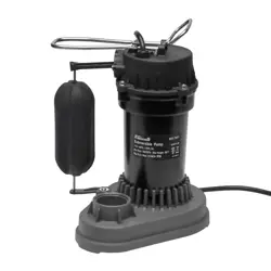
Submersible Pump
SKU: 76051
Owner's Manual
76051
E248578
Q500213M
USC
LISTED
26XZ

CAUTION!
This Pump Has Been Evaluated for Use With Water
Only
WARNING -“Risk of electric shock - This pump is
supplied with a grounding conductor and ground-
ing CAUTION ! type attachment plug. To reduce the
risk of electric shock, be certain that it is connect-
ed only to proper-ly grounded, grounding-type
receptacle”.
TABLE OF CONTENTS
BOX CONTENT AND TOOLS NEEDED 2
START GUIDE 3
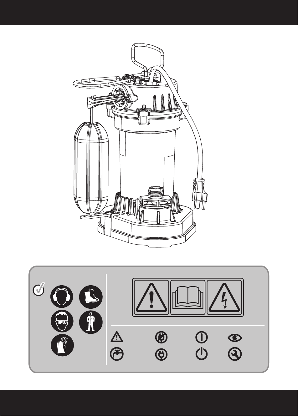
INTRODUCTION AND SAFETY 4
INSTALLATION AND COMMISSIONING 6
OPERATION 9
TROUBLESHOOTING 10
MAINTENANCE 11
TECHNICAL DATA 12
PARTS LIST 13
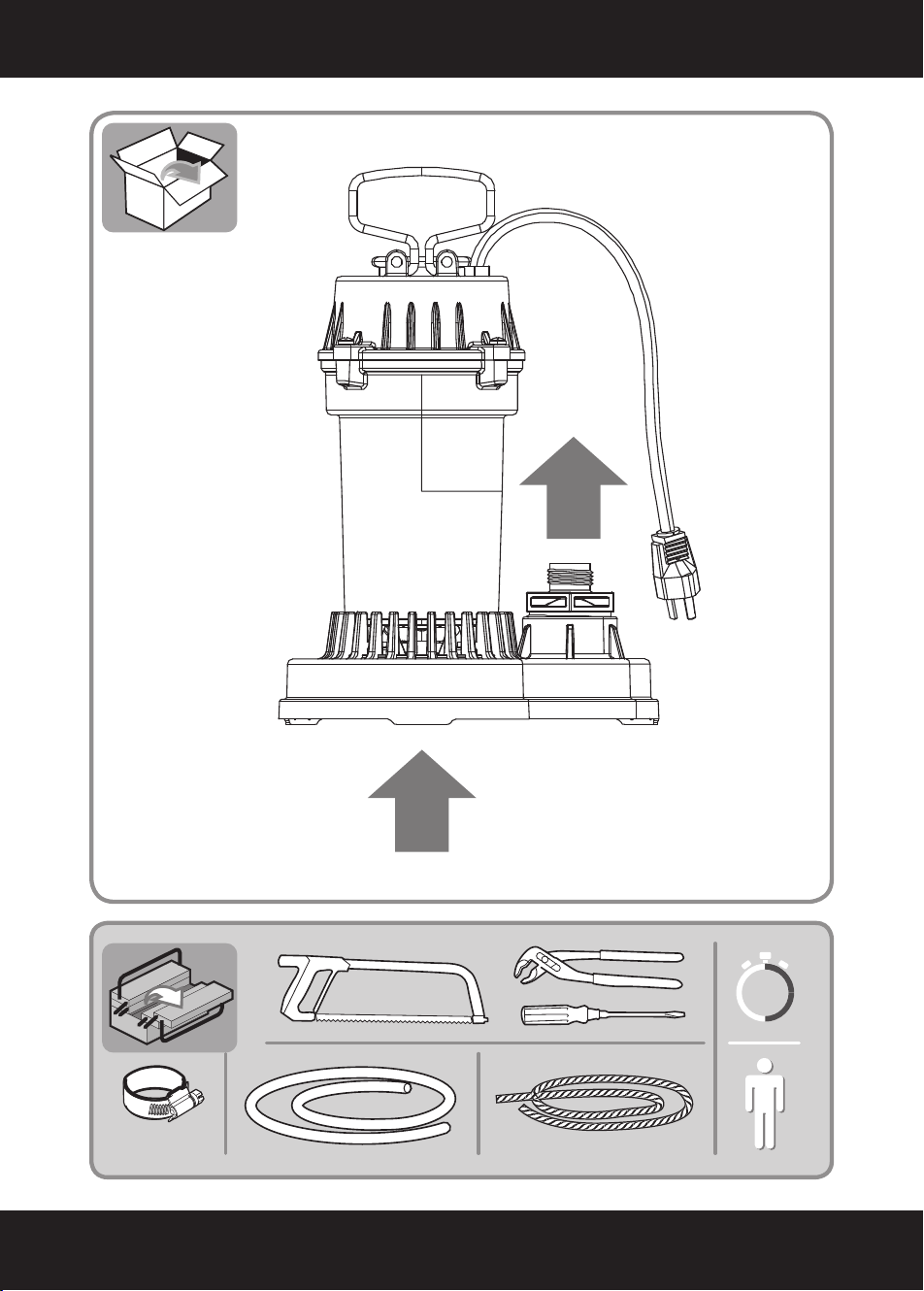
BOX CONTENT AND TOOLS NEEDED
2
IN
X1
30’
OUT
START GUIDE
3
Attention danger
Observez
Not connected
Connected
Power up
Stop
Clean Water
Environment
Maintenance

Thank you for purchasing this product.Please read these
instructions, and keep them for future reference.
This tool is an electric pump. It is used for pumping water and
other similar water applications.
After opening the package, please ensure that the products are
complete (if any).
If the products are damaged or there is something missing,
please do not use it and bring it back to your dealer.
If you give this tool to another person, please give him this
instruction manual.
Safety Instruction
1.All electrical sockets must be earthed.
2.No power cord should be used for transporting or fixing the
equipment.
3.Don't pull the power cord on the sharp edge and don't press
the power cord.
4.The power supply voltage must be the same as the voltage
given on the model board.
5.To avoid hazards, all installation and replacement of compo -
nents can only be carried out by authorized customer service
personnel.
6.Electrical connections can only be performed by electrical
professionals, and please comply with state regulations for this.
7.The pump must be connected with a current type leakage
current breaker which carry a rated leakage current of no more
than 30 MA.
8.Check the connection of the plug before running. If the wire is
damaged, it must be replaced by the manufacturer, the agent or
the relevant technical personnel to avoid any danger.
INTRODUCTION AND SAFETY
4

9.The device is suitable for children at eight or older. People
with sensory or physical disabilities or deficiencies are required
to use under supervision or knowledge of safety, use and
danger.
Children are not allowed to wash or maintain equipment without
supervision.
10.Liquid contamination may be caused by leakage of lubri-
cat-ing oil.
11.The water pump can be connected with a shock proof plug
installed in accordance with the regulations.
12.Do not use pumps when there is someone in the water.
13.When cleaning and maintaining, please disconnect the
water pump from the main power supply.
14.Please contact technical staff .
15.Connectors for power plugs and extension cables must be
made sure that they are watertight and must not be placed in
the water. Furthermore, connectors cannot be placed on the
ground. It is recommended to ensure that the outlet is at least
60 mm from the ground.
Attention!
None follow of the safety tips will have the life risk
brought by the current!
Danger!
Danger type and source:
None follow of the safety tips will have the life risk
brought by the current!
Do not repair the power cord if there is any exter-
nal damage to the power cord or plug.
INTRODUCTION AND SAFETY
5

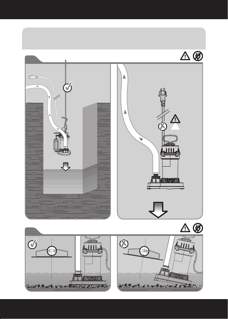
Long enough and strong ropes should be attached to thehandle
before the first use. When the pump is immersed into the liquid,
the rope along with a handle can be used to balance the pump.
Installation
The equipment requires an area of at least 60x60cm.
Depth of equipment immersed in technical parameters.
When installing the equipment, make sure the open will not the
suction opening will not be blocked by foreign objects to keep
the equipment stable.
Attention:
For rope handling: Do not operate the pump with-
out the pressure hose to prevent the pump from
twist-ing around its longitudinal axis. In continuous
use of a pump with a rope, the condition of the
rope must be checked periodically, as it may break
with increasing use time.
Attention!
Risk for equipment damage!
Do not lift the pump by cable or pressure
hose,be-cause these cables or pressure hoses are
not designed for tensile strength from pump weight.
The float switch must be able to move freely and
the submersible pump cannot be used in a dry
environ-ment.
INSTALLATION AND COMMISSIONING
6
INSTALLATION AND COMMISSIONING
7
2
1
NO
Before The Start
INSTALLATION AND COMMISSIONING
8
A
B
43
5
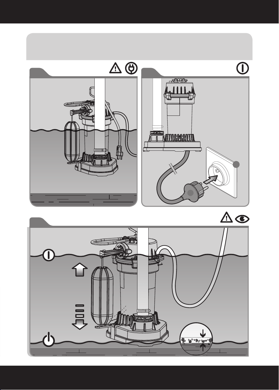
ON
OFF
Grain size
1/5 INCH
Start Up

Connecting pressure pipe
-screw the pressure pipe onto the pressure connector. All joint
connections must be sealed with a threaded sealing stripe.
-When using the hose, screw the right hose adapter into the
pressure connector.
-Secure the hose firmly to the hose adapter and secure it with a
hose clamp.
If it is used occasionally, please use a suitable pipe. A rigid pipe
with a check valve is recommended for use in a fixed position.
This can be done at the close of the machine to prevent liquid
backflow.
Use a strong rope to connect the handle of the pump and dip it
into the liquid to be conveyed at a certain angle, so that the
lower side of the device has no bubble formation to prevent the
bubbles from being sucked in. Put the equipment down slowly,
and once the pump is submerged, it can be adjusted again. The
pump is arranged at the bottom of a liquid container, Fasten the
end of the rope after lowering so that the pump can also be
handled when hanging on the rope. The pump can work after
the device is connected to the main power source.
The pump is not allowed to transport corrosive
substances, flammable and explosive substances
(such as gasoline, petroleum, nitro diluent),
grease, oil, brine and toilet equipment sewage,
as well as low mobility mud sewage. The tempera-
ture of the liquid cannot exceed 95°F.
OPERATION
9

In most cases, you will be able to troubleshoot problems easily
by yourself. Before you contact us, please refer to the following
table for technical support. This will help you save a lot of work
and possible expenses.
Error
Reasons
Errorshooting
The pump
1.Unconnected power.
1.Check power supply.
cannot
2.The float switch is
2. Check the float.
start
not turned on.
No water
1.Inlet obstruction.
1.Clean the inlet .
2.The pressure hose
2.Adjusting hose .
is bent .
The pump
1.The floater cannot
1.Put the pump in the
cannot
sink.
vertical well bottom
close
correctly.
Too small
1.Inlet obstruction.
1.Clean the inlet.
flow rate
2.Debris and particles
2.Clean the pump and
cause the wear of a
replace worn parts.
critical part of the
pump which reduces
the flow of the pump.
Close the
1.If the water is too
1.Disconnect the main
pump
dirty, the pump may
power supply and clean
after a
stall, and the heat
the water pump .
short
protector will cut off
2.Ensure that the maxi-
period
the water pump motor
mum water temperature is
of time
power supply .
not exceeded 95°F.
2.If the water tempera-
ture is too high, the
heat protector will cut
off the water pump
motor power supply .
10
TROUBLESHOOTING

Clean the equipment from the outside.
Flush with clean water. Use brush and detergent to remove
stubborn pollution. Immerse the pump into a container with
clean water, open it for running a while, and flush it in the pump.
Storage
If there is a risk of frost, remove equipment and accessories,
and clean and store it a place protected from frost.
Using scope
The pump is mainly used in a basement. When installed at the
bottom of the shaft, the pump prevents seeper in the basement.
It can also be used for water supply and drainage, such as
household, agriculture, gardening, pipelines and other suitable
occasions.
Process equipment
Products marked with adjacent symbols shall not be treated as
domestic rubbish. You must deal with these old electrical and
electronic equipment separately.
Please contact local authorities to see if they can be handled
properly. Make the old equipment available for recycling,-
pro-cessing, or other forms of second use by separate han-
dling. You can avoid polluting the environment by doing so.
Disposal packaging
The packing is made of cardboard and corresponding marking
plastic. These materials can be recycled.
Attention:
Before using the pump again, first "clean" to
pre-vent any possible dirt residue which could affect
the equipment operation.
Attention!
Risk for equipment damage!
Frost will destroy electrical appliances and accesso-
ries, because they always contain water.
11
MAINTENANCE

Technical data
Attention!
Risk for equipment damage!
The particle size mentioned cannot be used for
simple gravel or stone, but suitable for soft,
variability of particles or similar things which
cannot put into the water pump.
12
TECHNICAL DATA
Model
Voltage & Hz
Horsepower
Max. Pump Rate
Max. Grain Size
Dia. Of Pipe
Max. Height
76051
115 V / 60 Hz
1/2 HP
3800 GPH
30 FT
1/5 INCH
NPT 1-1/2 INCH
Water Temperature
Shaft
Cable Length
Protection Type
Outlet
Pump Housing
95°F / 35°C
#420 S.S
10 FT
A413 Aluminum Alloy
IPX8
NPT1-1/2 INCH
Certification UL
5A
Current
13
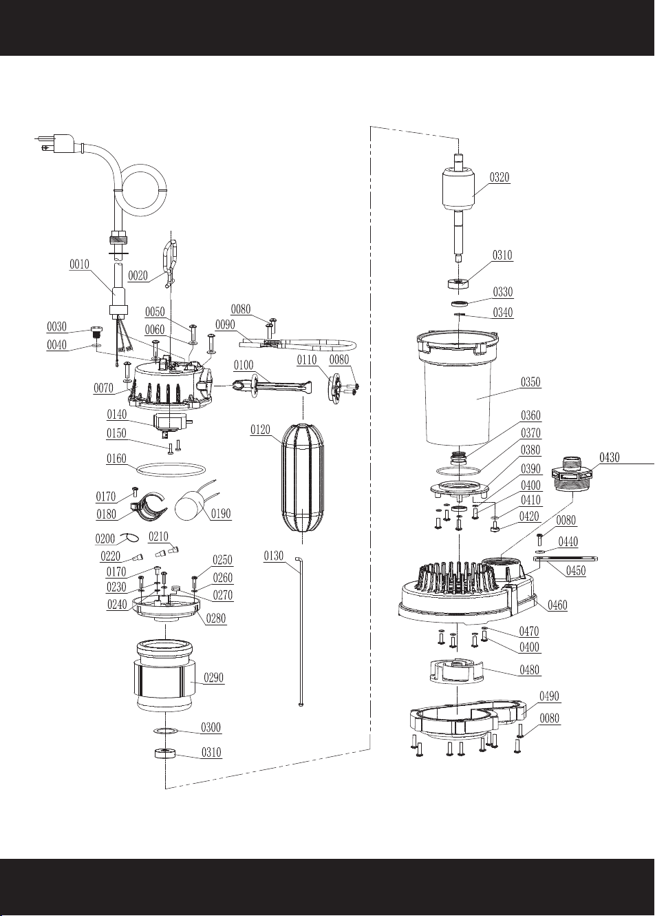
PARTS LIST
14
PARTS LIST
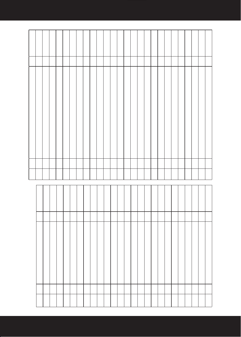
PARTS# NO. item QTY UNIT
P76051-0010
0010
POWER CORD
1
PCS
P76051-0020
0020
HANDLE
1
PCS
P76051-0030
0030
SEALING BOLT
1
PCS
P76051-0040
0040
O-RING
1
PCS
P76051-0050
0050
HEXAGON SOCKET H
EA
D
CAP SCREWS
4
PCS
P76051-0060
0060
SERRATED LOCK WASHERS INTERNAL TEETH 4
PCS
P76051-0070
0070
REAR PUMP CASE 1
PCS
P76051-0080
0080
CROSS HEAD TAPPING SCREW
5
PCS
P76051-0090
0090
FENDER BRACKET
1
PCS
P76051-0100
0100
SWITCH LEVER 1
PCS
P76051-0110
0110
COVER PLATE 1
PCS
P76051-0120
0120
FLOATING BALL 1
PCS
P76051-0130
0130
FLOATING BRACKET
1
PCS
P76051-0140
0140
MICROSWITCH 1
PCS
P76051-0150
0150
CROSS
HEAD TAPPING SCREW
2
PCS
P76051-0160
0160
O-RING 1
PCS
P76051-0170
0170
CROSS HEAD TAPPING SCREW 2
PCS
P76051-0180
0180
CAPACITOR SHEATH 1
PCS
P76051-0190
0190
25UF/250V CAPACITOR
1
PCS
P76051-0200
0200
CABLE TIE
1
PCS
P76051-0210
0210
NYLON SECURE LINE PRESSING CAP 2
PCS
P76051-0220
0220
NYLON SECURE LINE PRESSING CAP
1
PCS
P76051-0230
0230
SPRING WASHER 1
PCS
P76051-0240
0240
EXTERNAL SERRATED LOCK WASHER
1
PCS
P76051-0250
0250
CROSS HEAD TAPPING SCREW 3
PCS
P76051-0260
0260
SPRING WASHER 3
PCS
PARTS# NO. item QTY UNIT
P76051-0270
0270
CONDUCTOR SHEATH
1 PCS
P76051-0280
0280 ALUMINUM REAR COVER 1 PCS
P76051-0290
0290 STATOR
1 PCS
P76051-0300
0300 CORRUGATED GASKET
1 PCS
P76051-0310
0310 BEARING 2 PCS
P76051-0320
0320 ROTOR
1 PCS
P76051-0330
0330 SKELETON SEAL RING
2 PCS
P76051-0340
0340 SHAFT RING 1 PCS
P76051-0350
0350 ALUMINUM COVER 1 PCS
P76051-0360
0360 MECHANICAL SEAL
1 PCS
P76051-0370
0370 O-RING 1 PCS
P76051-0380
0380 ALUMINUM FRONT COVER
1 PCS
P76051-0390
0390 SPRING WASHER
4 PCS
P76051-0400
0400 CROSS HEAD TAPPING SCREW 8 PCS
P76051-0410
0410 O-RING 1 PCS
P76051-0420
0420 SCREWS
1 PCS
P76051-0430
0430 ADAPTER
1 PCS
P76051-0440
0440 FLAT GASKET 1 PCS
P76051-0450
0450 FLOATING BALL SUPPORT
1 PCS
P76051-0460
0460 PUMP BASE
1 PCS
P76051-0470
0470 FLAT GASKET 4 PCS
P76051-0480
0480 IMPELLER 1 PCS
P76051-0490
0490 BASEPLATE
1 PCS
P76051-0500
0500 CROSS HEAD TAPPING SCREW 9 PCS
P76051-0510
0510 25# TRANSFORMER OIL
0.68
FL OZ

CUSTOMER SERVICE
If you have any questions about ordering our outdoor furnitures and replacement parts or other furniture
products, please feel free to contact us using the following contact information:
Customer Service and Technical Support
Phone: (909) 628-0880
Email: [email protected]
Hours of Operation: Monday – Friday, 9AM – 4PM (CST)
DISCLAIMER
PLEASE READ THE FOLLOWING CAREFULLY
The manufacturer and/or distributor have provided the parts list and assembly diagram in this manual for
reference purposes only. They do not make any representation or warranty to the buyer that they are qualified
to make repairs to the product or replace any parts of the product. In fact, the manufacturer and/or distributor
expressly state that all repairs and parts replacements should be undertaken by certified and licensed
technicians, and not by the buyer.
The buyer assumes all risk and liability arising from their repairs to the original product or replacement parts
or arising from their installation of replacement parts. It is strongly advised that qualified professionals handle
any repairs or replacements to ensure safety and proper functioning of the product. Improper installation and
operation may result in injury, property damage, or voiding of warranty. The manufacturer and/or distributor
shall not be held responsible for any accidents, damages, or malfunctions resulting from the buyer's
installation and operation of the product. It is essential to follow all safety guidelines and recommendations
provided in this manual and to seek professional assistance if unsure about the installation or operation
procedures.
