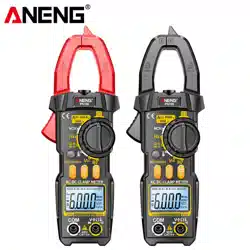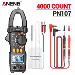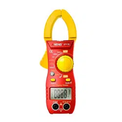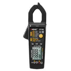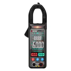
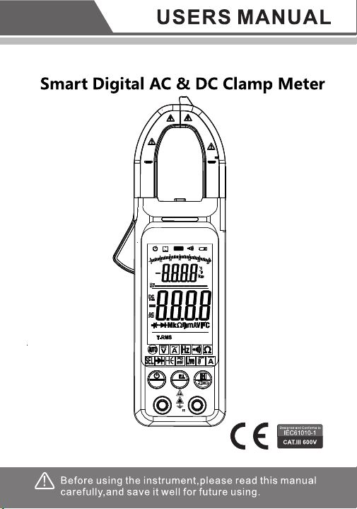
Intelligent digital clamp multimeter
NCV
INPUT
!
CAT
MAX 6 00V
COM
AUT O
6000Count s
NCV
MAX
400A
CAT II
600V
CATIII
300V
SEL
R
SEL
NCV
INPUT
!
CAT
MAX 6 00V
COM
AUT O
6000Count s
NCV
MAX
400A
CAT II
600V
CATIII
300V
R
1. Safety Information
Warning
Pay special attention to use of this instrument, for
improper use may cause electric shock or damage to
instrument.
During use, observe usual safety regulations
and observe safety measures regulated in use manual.
In order to make full use of instrument functions and
guarantee safe operation, please careful
ly read and
observe use methods in this manual.
Instrument complies with safety requirements on
electronic measuring instrument of EN-61010-1,
EN-61010-2-030 and EN-61010-2-032, level II pollution,
and over-voltage standard is CAT II
600V.
Please observe safety operation guide, and guarantee
to use instrument in a safe manner.
1.1 Preparation
1.1.1 When using this instrument, users must observe
standard safety rules:
- General electric shock prevention.
- Prevention of misuse of instrument.
1.1.2 After receiving the instrument, check whether it is
damaged during transportation.
1.1.3 After storing and shipping under adverse conditions,
check whether the instrument has been damaged.
1.1.4 Pens of the instrument must be in good
condition.
Before use, check whether insulation of pens is
damaged, and whether metal wire is exposed.
1
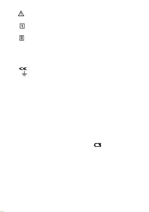
1.2 Symbol
Note (refer to use manual for important safety
information)
Able
to be used on dangerous electrified
conductors.
Dual-insulation protection (Category II)
CAT III
Over-voltage according to IEC-61010-1 standard
(installation), level III, pollution degree 2 refers
to protection level of pulse withstand voltage
provided.
Comply with EU standard.
Grounded
1.3 Maintenance
1.3.1 Do not try to open bottom case to adjust or repair
instrument, for such operation could only be
conducted by technicians fully understanding the
instrument and electric shock danger.
1.3.2 Before opening instrument bottom case or battery
cover, remove the pens from the wire being
measured.
1.3.3 In order to avoid electric shock possibly caused by
error reading, when symbol " " displays on
instrument, replace battery immediately.
1.3.4 Use wet cloth and gentle detergent to clean the
instrument, and do no use any abrasive or solvent.
1.3.5 Power off when the instrument is not used, and rotate
range switch to OFF position.
1.3.6 If the instrument is not used for a long time, take out
the battery to avoid any damage to the instrument.
2
2. Description
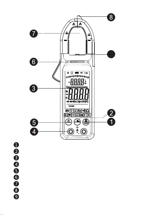
2.1 Part name
Data hold and flashlight button
Eletric torch
Input socket
Caution light
Contactless induction zone
LCD display
REL DC current back to zero /NCV button
Current measuring clamp
Power button /SEL function conversion button
NCV
INPUT
!
CAT
MAX 6 00V
COM
AUTO
6000Counts
NCV
MAX
400A
CAT II
600V
CATIII
300V
9
3
SEL
R
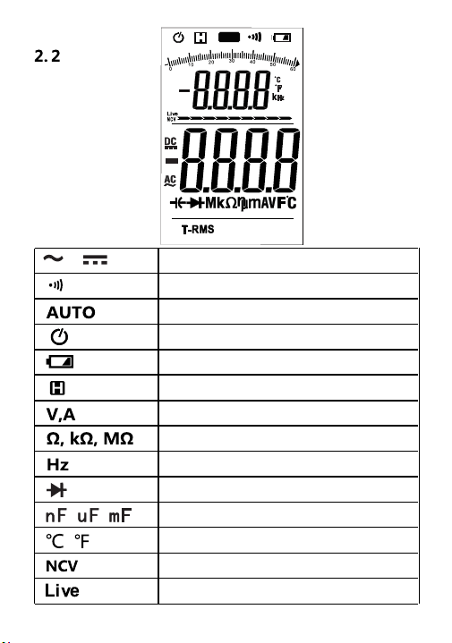
AC & DC
Connection/Disconnection indication
Automatic range mode
Automatic shutdown indication
Low battery
Reading hold state
Volt (voltage), ampere (current)
Ohm
kilohm and megohm (resistance)
hertz
icrofarad
Centigrade and Fahrenheit
LCD display
DIODE
AUTO
6000Counts
Non-contact measuring voltage
Live line voltage identification
4

3. Specification
The instrument specifies one year as a cycle, and shall
be re-calibrated under 18℃ ~ 28℃, with relative humidity
less than 75%.
3.1 Overview
●
Select measurement function and range automatically.
● Overload protection throughout the range.
● Max. voltage between measurement terminal and
ground: 600V
DC or 600V AC
● Operating height: Max. 2000m
● Display: LCD
● Max. display value: 6000 digit.
● Polarity indication: Automatic indication, and ‘-’
indicates negative.
● Over range display: ‘0L’ or ‘-0L’.
● Sampling time: About 3 times/second.,bargraph 10
times/second
● Unit display: Function and electricity quantity unit
display.
● Automatic shutdown time: 15 minutes
● Power supply: 1.5V AAA battery × 2
● Battery under-voltage indication: LCD
display
symbol
● Temperature coefficient: Less than 0.1×accuracy/℃.
● Operating temperature: 18℃ ~ 28℃.
● Storage temperature: -10℃ ~ 50℃.
5
3.2 Technical indexes
3.2.1 AC current
Range
Resolution
Accuracy
60A
0.01A
± (2.5% reading + 30 digits)
0.1A
- Min. input current: 1.0A AC current in automatic mode;
- Max. input current: 400A
AC current.
- Frequency range: 40~ 1000Hz;
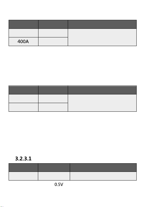
3.2.2 DC current
Range
Resolution
Accuracy
60A
0.01A
± (2.5% reading + 30
digits)
400A
0.1A
- Min. input current:
- Max. input current: 400A DC current
3.2.3 DC voltage
Range
Resolution
Accuracy
± (0.5% reading + 5 digits)
600V
0.1V
- Min. input voltage DC
- Max. input voltage: 600V DC
Dc voltage V
6
Manual mode 0.2A AC current
Manual mode 0.2A DC current
Note: DC current accuracy refers to the above accuracy
when the return to zero mode is enabled.
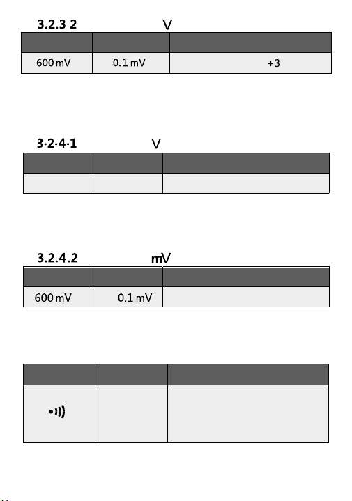
3.2.4 AC voltage
Range
Resolution
Accuracy
±( 0.8% reading + 5 digits)
600V 0.1V
-
Min. input voltage: 0.5 V AC
- Max. input voltage: 600V AC (valid value)
- Frequency range: 45 ~ 1000Hz
3.2.5
Range Resolution Accuracy
±( 0.8% reading + 5 digits)
- Min. input voltage: 0.1 mV AC
- Max. input voltage: 600V AC (valid value)
AC voltage
AC voltage
Line on-off test
Range
Resolution
Function
1Ω
Ω
- Overload protection: 250V DC or AC (valid value)
If the measured line
resistance is less than 50 ,
the buzzer in the meter will
sound
7
m
Range
Resolution
Accuracy
± (0.5% reading + digits)
- Min. input voltage 0.
1m
V DC
-
Max. input voltage:
600V DC
Dc voltage
8
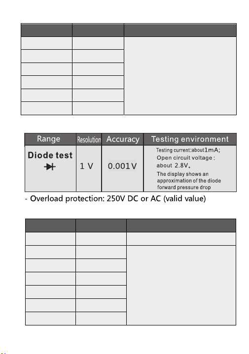
- Overload protection: 250V DC or AC (valid value)
Range
Resolution
Accuracy
60.00nF
0.01nF
600.0nF
0.1nF
6.000uF
1nF
60.00uF
10nF
600.0uF
100nF
6.000mF
1μF
60.00mF
10μF
- Overload protection: 250V DC or AC (valid value)
±( 10%reading+40 digits)
±( 2.5%reading+20 digits)
3.2.7 DIODE
3.2.8 Capacitor
3.2.6 Resistance
Range
Resolution
Accuracy
600Ω 0.1Ω
± (0.8% reading + 3 digits)
6kΩ 0.001kΩ
60kΩ
0.01kΩ
600kΩ 0.1kΩ
6MΩ 0.001MΩ
60MΩ 0.01MΩ
9
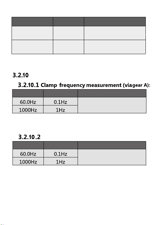
Frequency
Range Resolution Accuracy
Range Resolution Accuracy
±( 1% reading + 5 digits )
±( 1% reading + 5 digits )
-
Measurement range: 40Hz ~ 1000Hz
- Input signal range: ≥1/4
Full- scale Value
Via gear V:
-
Measurement range: 40Hz ~ 1000Hz
- Input signal range: ≥0.5~600V
AC voltage (valid value)
3.2.9 Temperature
Range Resolution
Accuracy
1℃
± (1%
reading
+3℃)
2℉ ± (1%
reading +3℉)
- Overload protection: 250V DC or AC (valid value)
The precision does not include the error of the thermocouple probe
-40 °C~
1000°C
-40 °F~
1832°F
4. Operation guide
4.1 Reading hold
During measurement, if it is required to hold
reading,
touch
button,
value on display
will be locked, touch
button again, to cancel reading hold.
4.2 Torch
1)
4.3
10
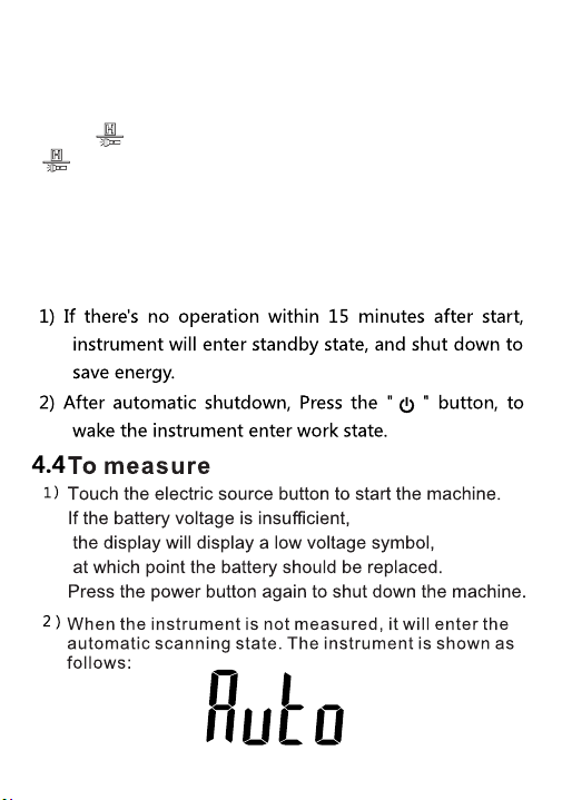
Long press the flashlight button for 2 seconds, turn on
the flashlight, and turn it off after about 1 minute.
Auto Power -Off
11
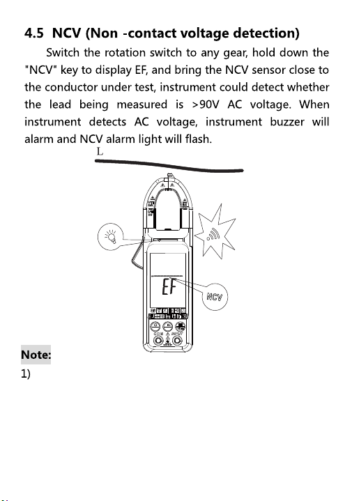
Even if there is no alarm indication, the voltage may
still be present. Do not rely on the non-contact voltage
to determine whether a wire has a voltage.
Probe operation may be influenced by socket design,
type of insulation thickness, etc.
In NCV detection mode, the meter does not measure
voltage, resistance, and current simultaneously.
SEL
NCV
R
12
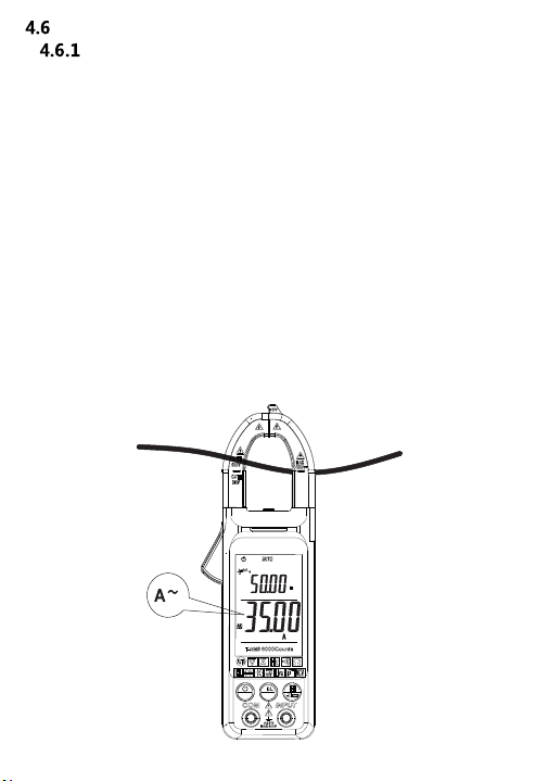
electric current measurement
Ac current and AC current frequency measurement
Automatic mode measurement:
1) Hold the trigger, open the clamp head, and clamp a wire of the
tested line in the clamp.
2) When the measured signal >1A, the instrument main display
screen displays the measured current value
(Note: only when the current value is >35A,the instrument
auxiliary display will display its frequency value)
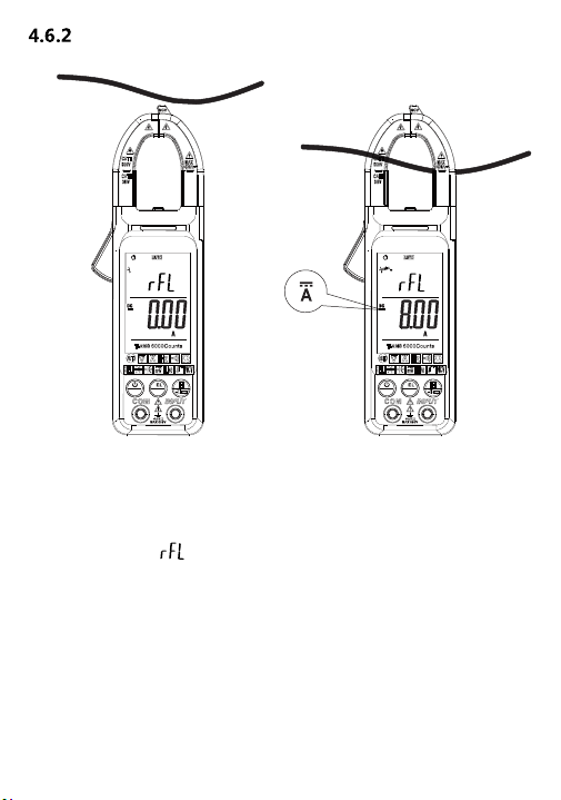
Manual mode measurement:
1) Press SEL key to switch to AC current, hold the trigger, open
the clamp head,
Clamp one of the wires of the line under test in the clamp.
2) When the measured signal > 0.2a, the main display screen
of the instrument will display the measured Current value.
SEL
NCV
R
Dc current measurement
Manual mode measurement:
1) Press SEL key to switch to DC current mode.
2) The front end of the clamp head is close to the measured
wire. Press the REL button to make its base close to zero,
Vice display character.
3) Hold the trigger, open the clamp head, and clamp a wire of
the tested line in the clamp.
4) When the measured signal > 0.2a, the main display screen
of the instrument shows the measured current value.
Note: To get an accurate reading, press the "REL" key
to reset the meter to zero before measuring.
13
SEL
NCV
R
SEL
NCV
R
14
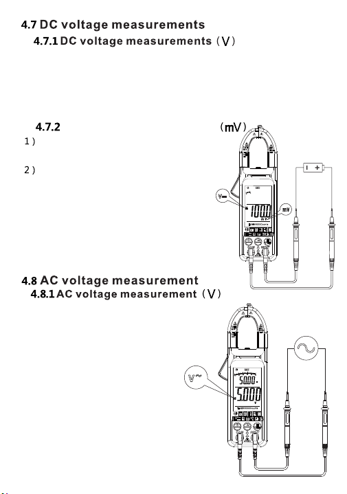
Connect the test pen to the signal
being tested.
When the measured AC signal is
greater than 0.5V, the display
displays the voltage and
frequency values.
When the measured
AC signal <0.5V, the instrument
default resistance value, display
the measured signal internal
resistance value.
Press SEL button to dc voltage mV,
the instrument shows mV
Dc voltage measurement
Connect the test pen to the test signal.
When the test signal is <600mV,
the instrument will display the current
dc voltage value under test;
when the test signal is >600mV,
the instrument will display "OL".
Connect the test pen to the signal being tested. When the
measured DC signal is greater than 0.5V, the display voltage
value. When the measured DC signal is <0.5V, the instrument
uses the default resistance value and displays the resistance
value of the measured signal.
SEL
NCV
R
SEL
NCV
R
15
Press SEL to enable the mV function. Instrument display mV
Connect the meter and meter pen to the signal under test.
When the measured signal is less than 600mV,
the meter displays the measured current
dc voltage value.
When the measurement signal
is > 600mV, the instrument
displays "OL".
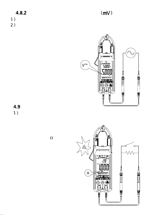
Ac voltage measurement
resistance measurement
Connect the test pen to the resistance to be measured.
The main display of the instrument will display the measured
resistance value.
When the measurement resistance
is less than 50 ,
the instrument buzzer
sound alarm, indicator
light on.
SEL
NCV
R
SEL
NCV
R
16
5. Maintenance
5.1 Change battery
Warning
Before opening battery cover of the
instrument, remove the pens from the circuit being
measured, to avoid electric shock.
1) If symbol "
" appears, it indicates to change the
battery.
2) Unfasten bolts on battery cover of instrument and
remove the cover.
3) Change the old battery.
4) Place the battery cover.
Do not reverse battery polarity.
17
5.2 Change pens
Warning
When changing the pen, it is required to
replace with an identical pen or a pen of the same
level.
The pen must be in good condition, and level
of the pens is: 1000V 10A.
If insulation layer of the pen is damaged, or metal wire
of the lead exposes, it is required to change the pen.
6. Accessories
1)
Pens
Level: 1000V 10A
2) Use Manual
3) Battery
1.5V AAA battery
4)
K-Type
Optional function
accessories
2PCS
1PCS