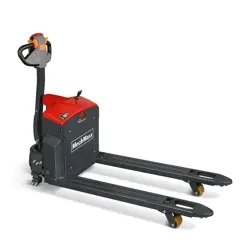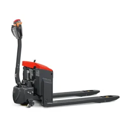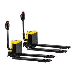

Thank you for choosing our
electric pallet truck!
Hope they will provide great convenience for your work!
⚫ Please read the manual carefully before starting the truck.
⚫ This operation manual is general, and the right to make any technical
modifications to the pallet jacks is reserved. Contents provided in this
manual are for reference only.
Contents
1. Safety regulations .............................................................................................................. 1
2. Allowed environment for using ......................................................................................... 2
3. Technical parameters ......................................................................................................... 3
4. Handle installment ............................................................................................................. 2
5. Operation ........................................................................................................................... 3
6. Use, maintenance and charging of storage battery .......................................................... 8
7. Maintenance ....................................................................................................................... 8
8. Truck hoisting .................................................................................................................. 10
9. Trouble shooting .............................................................................................................. 10
10. Waste treatment ........................................................................................................... 11
11. Accessories and spare parts ......................................................................................... 11
12. Electrical schematic diagram and fault code ............................................................... 12
13. Packing list .................................................................................................................... 23
1
1. Safety regulations
Safety shoes are always required to handle the pallet truck.
Safety glasses are recommended to avoid personal accidents while assembling or
disassembling the pallet truck.
CAUTION
When the truck is damaged or has safety problems, stop using it immediately.
CAUTION
The pallet truck is designed for hard and flat floor only.
It’s forbidden to use the truck when :
- the air contains dust or flammable and explosive gases that can cause fire or explosion。
- in freezer or some low temperature, salty or other corrosive environment.
- Rainy outdoor.
- Operate on gravel or grassland.
- the gradient of the ground is greater than the gradient of product design.
CAUTION
- Careful judgment and responsible attitude should be taken in the operation of pallet
trucks.
- The pallet truck is not able to be operated with oily hands or shoes
- Operators shall not wear loose clothes or jewelry
CAUTION
- When operating the pallet truck, it is necessary to ensure that the ground has sufficient
load bearing capacity, where the load is the sum of the weight of the pallet truck and the
load.
- Special care should be taken if there are prominent objects that can cause personal
injury
- Personnel are prohibited around the operating area of the pallet truck, which may cause
personal injury, for example, when the goods fall.
CAUTION
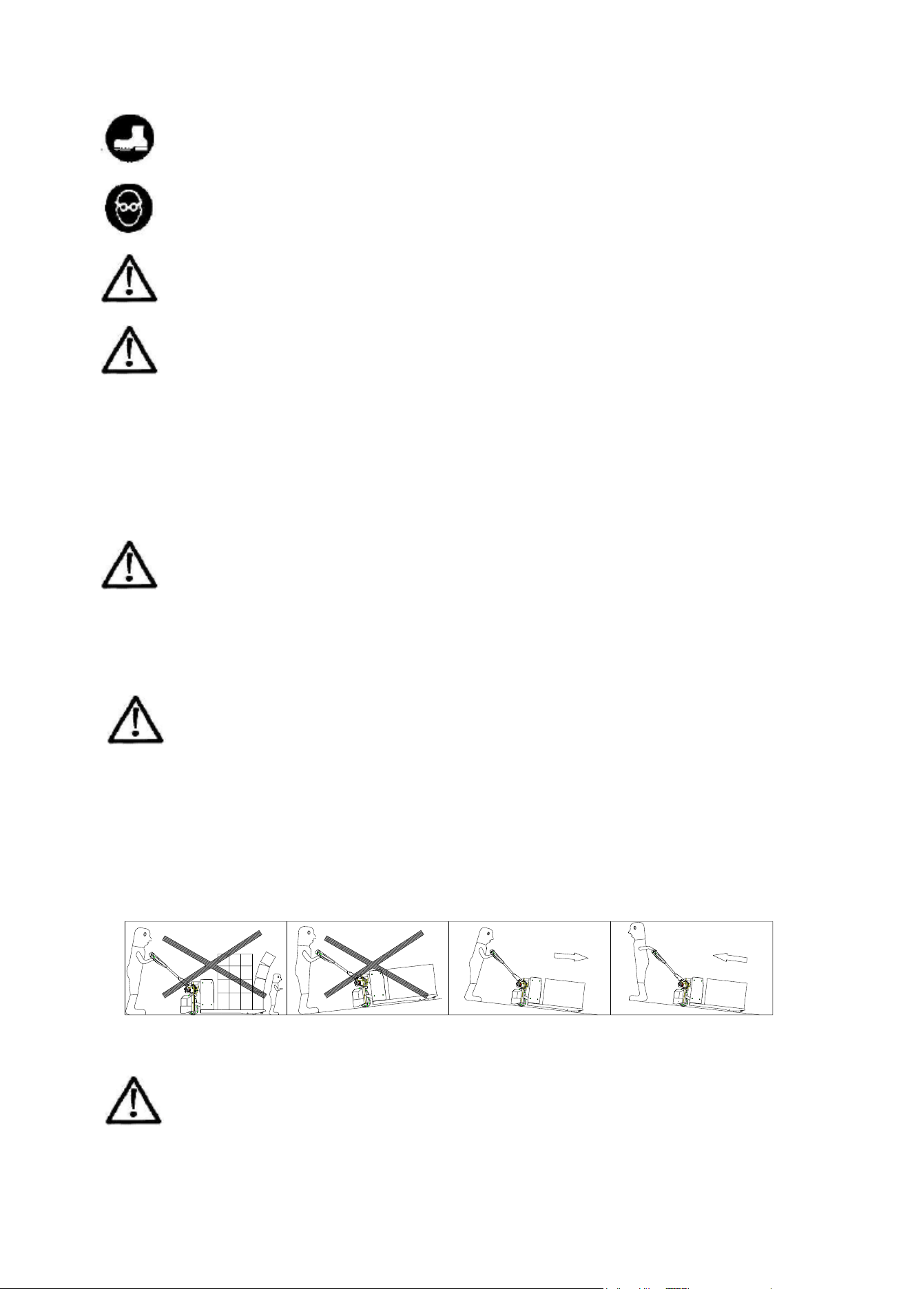
Operators must be very carefully when handling the pallet truck on a slope. See the drawing,
the operator should stand ahead of the truck. Operators must be very carefully when
handling the pallet truck on a slope. See the drawing, the operator should stand ahead of the
2
truck. When a truck runs on a ramp, the driving wheel can be quickly turned to the maximum
angle to avoid the risk that the truck will continue to slide. This method allows operation only
in emergencies.
WARNING!
- Avoid high-speed operation when turning to avoid the danger of overturning.
- The goods should not be too high to block sight.
- Brake gently and carefully to avoid cargo slipping off the pallet and causing material
damage.
- The pallet truck is not allowed to turn on the slope。
- Before pushing the pallet into the elevator, the operator must ensure that the elevator
can withstand the total load of the pallet and cargo, the total weight of the operator and
other personnel on the elevator. Make sure the load goes into the elevator first, then the
operator. The elevator should keep empty when the pallet truck with load is about to go
in/out of it.
CAUTION!
- The load shall not exceed the rated load of the truck。
- When stacking goods, the goods should not be too high to avoid the danger of falling
down or overturning the pallet truck during handling.
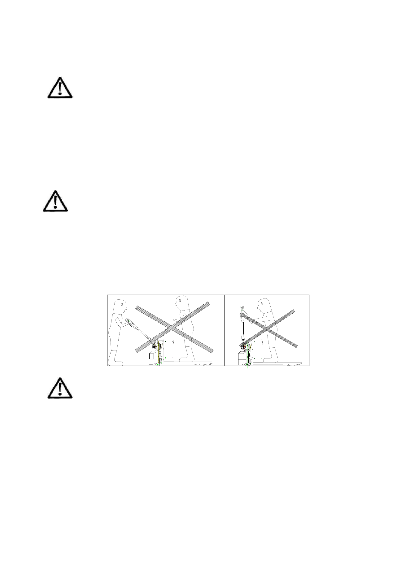
- It’s forbidden to ride people with the pallet truck.
- Keep clear of the pallet truck’s working area, avoiding personal injuries due to sudden
accidents happened over its working.
- Standing and sitting on the pallet truck is strictly forbidden.
CAUTION!
- Keep the fork at the lowest position while it’s parked.
- Don’t leave the truck on a slope.
- Don’t leave the truck at the emergency access.
- Don’t leave the pallet truck to block the traffic or affect work.
- Don’t use the pallet truck in rain.
- Turn off the power when the pallet truck is unattended.
2. Allowed environment for using
This truck is designed to work only on hard and flat floor, indoor. It is not allowed to work in an
environment beyond the regulations.
- Ambient temperature shall not be higher than +104℉and no lower than -50℉;
- Hard and flat ground;
- It is prohibited to use in a flammable, explosive or corrosive environment with acid and alkali;
3
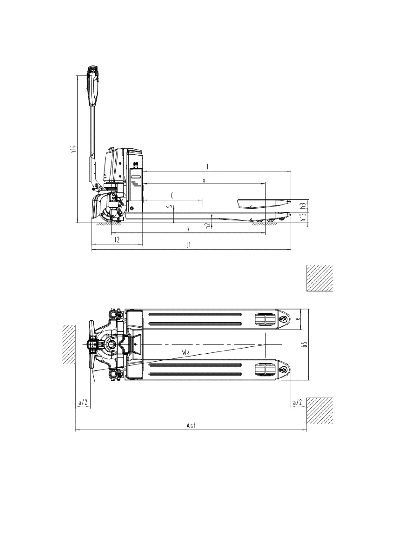
3. Technical parameters
Figure 1

1
Characteristic
1.2
Model
SKU58115
1.3
Drive: electric (battery type, mains, ...),
diesel, petrol, fuel gas
Electric
1.4
Operator type: hand, pedestrian, standing,
seated, order-picker
Pedestrian
1.5
Load capacity
Q
(lbs)
3300
1.6
Load center distance
c
(inch)
23 3/5
1.8
Load distance, centre of drive axle to fork
x
(inch)
37/40
1.9
Wheelbase
y
(inch)
47/50
Weight
2.1
Service weight
lbs
298
2.2
Axle loading, laden front/rear
lbs
1466/2138
2.3
Axle loading, unladen front/rear
lbs
209/88
Wheel chassis
3.1
Tyres: solid rubber, superelastic, pneumatic,
polyurethane
PU
3.2
Tyre size, front
Ф8 1/2×2 3/5
3.3
Tyre size, rear
Ф3×3 3/5
Ф3×2 3/5
3.4
Additional wheels (dimensions)
Ф2 1/3×1 1/3(option)
3.5
Wheel number, front/rear ( x = driving
wheel)
1X/2(4)
3.6
Tread, front
b
10
(inch)
18
3.7
Tread, rear
b
11
(inch)
15 / 20 1/2
4.4
Lift
h
3
(inch)
4
4.9
Height drawbar in driving position min./max.
h
14
(inch)
25 1/2 / 44 3/5
4.15
Height, lowered
h
13
(inch)
3
4.19
Overall length
l
1
(inch)
61/ 63 1/2
4.20
Length to face of forks
l
2
(inch)
15 1/2
4.21
Overall width
b
1
/
b
2
(inch)
21 3/5 / 26 3/5
4.22
Fork dimensions
S*e*l
(inch)
2 3/5*6 1/5*45 1/5(48)
4.25
Fork spread
b
5
(inch)
21 3/5 / 26 3/5
4.32
Ground clearance, centre of wheelbase
m
2
(inch)
1
4.34.1
Aisle width for pallets 1000x1200 crossways
A
st
(inch)
84 3/5 / 87
4.34.2
Aisle width for pallets 800x1200 lengthways
A
st
(inch)
79/81
4.35
Turning radius
W
a
(inch)
53/ 55 3/5
Parameter
5.1
Travel speed, laden/unladen
km/h
4.3/4.5
5.2
Lift speed, laden/unladen
inch/s
1/ 1 1/5
5.3
Lowering speed, laden/unladen
inch/s
1 1/3 /1
5.7
Gradeability, laden/unladen
%
5/20
5.10
Service brake
EM brake
Motor
6.1
Drive motor rating S2 60 min
kW
0.75
6.2
Lift motor rating at S3 15%
kW
0.8
6.4
Battery voltage/nominal capacity
V/Ah
24/20
6.5
Battery weight
lbs
11
10.7
Noise level at operator’s ear, according to
DIN12053
dB (A)
70
2
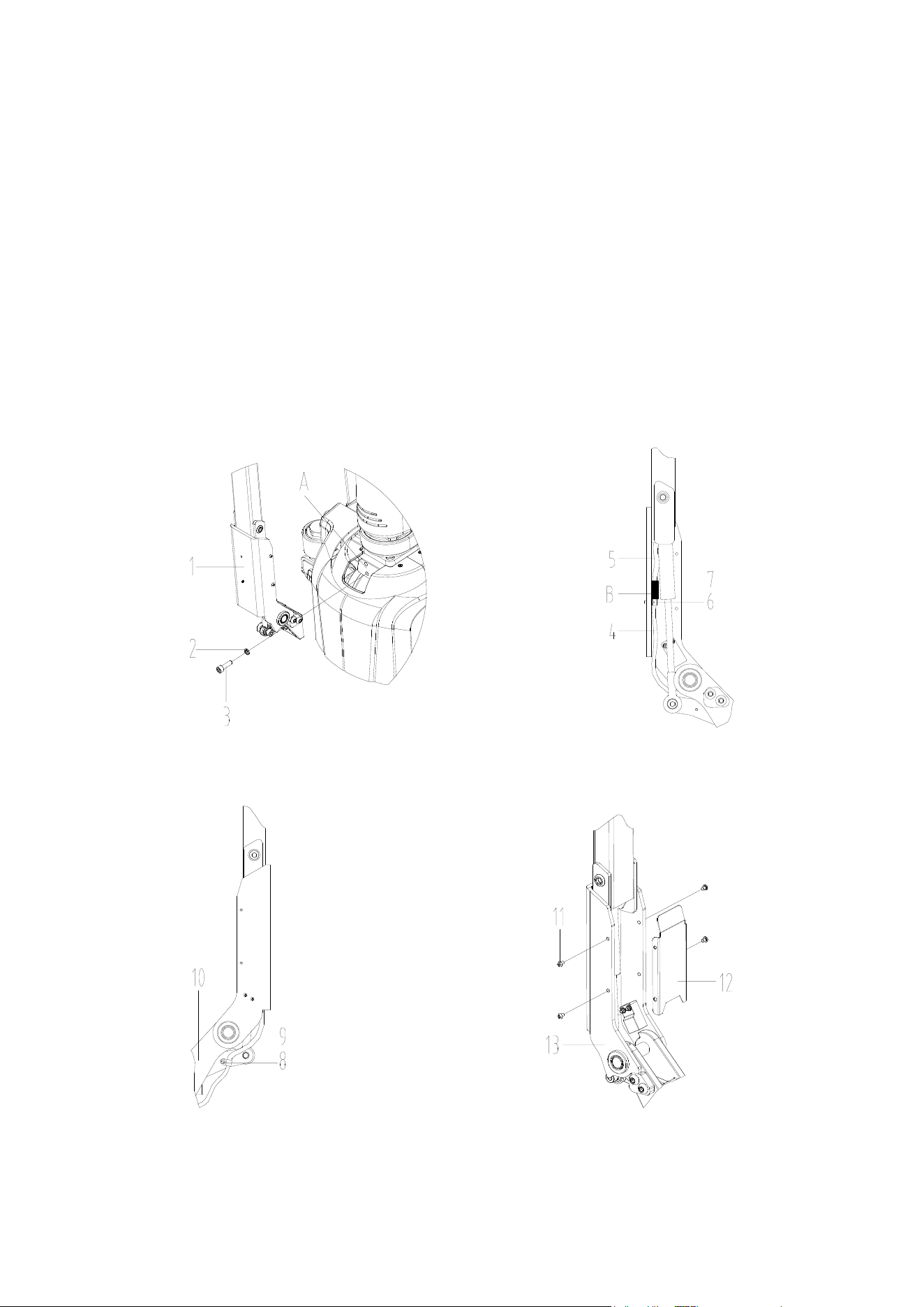
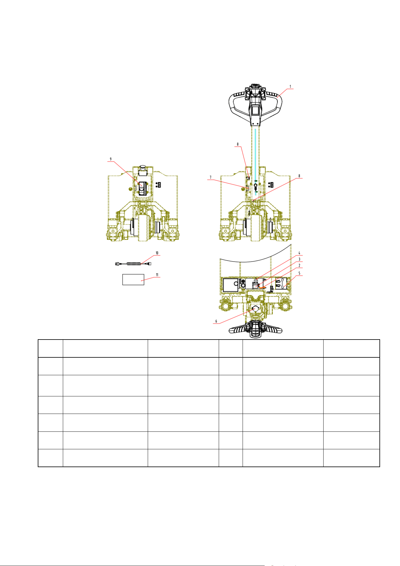
4. Handle installment
The handle is removed before shipment in the consideration of the requirement of packing and the
safety over transportation, and the steps to install the hand are list as following:
⚫ As shown in Figure 2, take out the handle assembly 1, align it with the installation position A, and fix
it reliably with screws 3 and washers 2.
⚫ As shown in Figure 3, connect the connectors of the truck body harness 4 and the handle harness 5
(pay attention to the alignment direction). As shown in B, fix the harness firmly with the wire clamp
6 and the screw 7.
⚫ As shown in Figure 4, fix the truck body harness 5 to the handle base 10 with screws 8 and line cards
9, press the handle down and slowly release it, observe whether the harness is properly fastened,
and then test whether the truck functions normally according to the truck operation instructions.
⚫ As shown in Fig. 5, fix the cover plate 12 to the handle assembly 13 with screws 11. After the above
steps, the handle installation is completed.
Figure 2 Figure 3
Figure 4 Figure 5
3
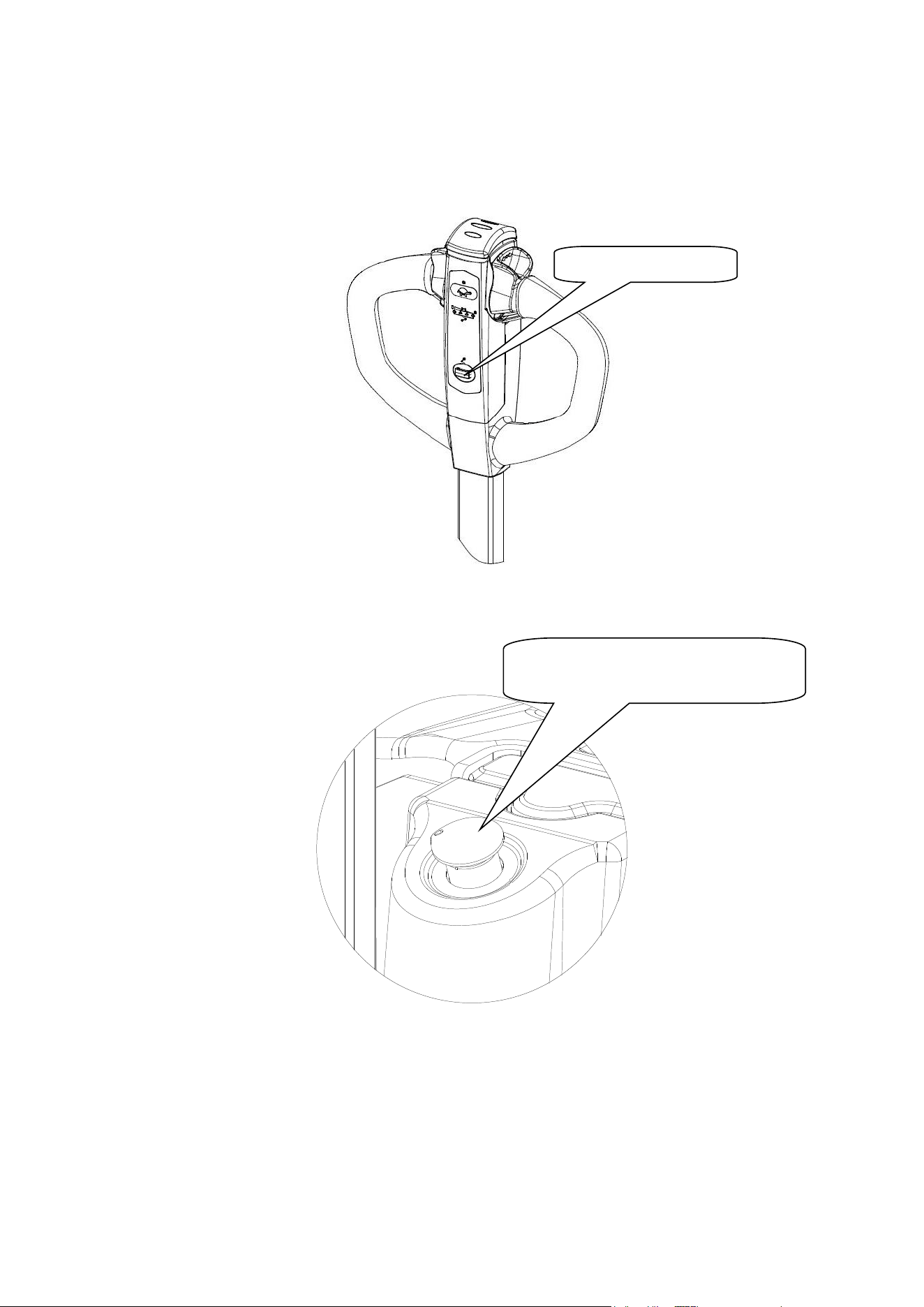
5. Operation
Truck electrified (magnetic lock)
- Turn on the electric lock
- Plug in the magnetic lock to turn on the truck easily.
Figure 6
- Turn on the emergency stop switch
Figure 7
Truck electrified (password lock)
- Turn on the password lock by entering the right initial password 1234 and pressing ON.
- Password lock introduction
Plug in electric lock
Turn clockwise to open the
emergency stop switch
6
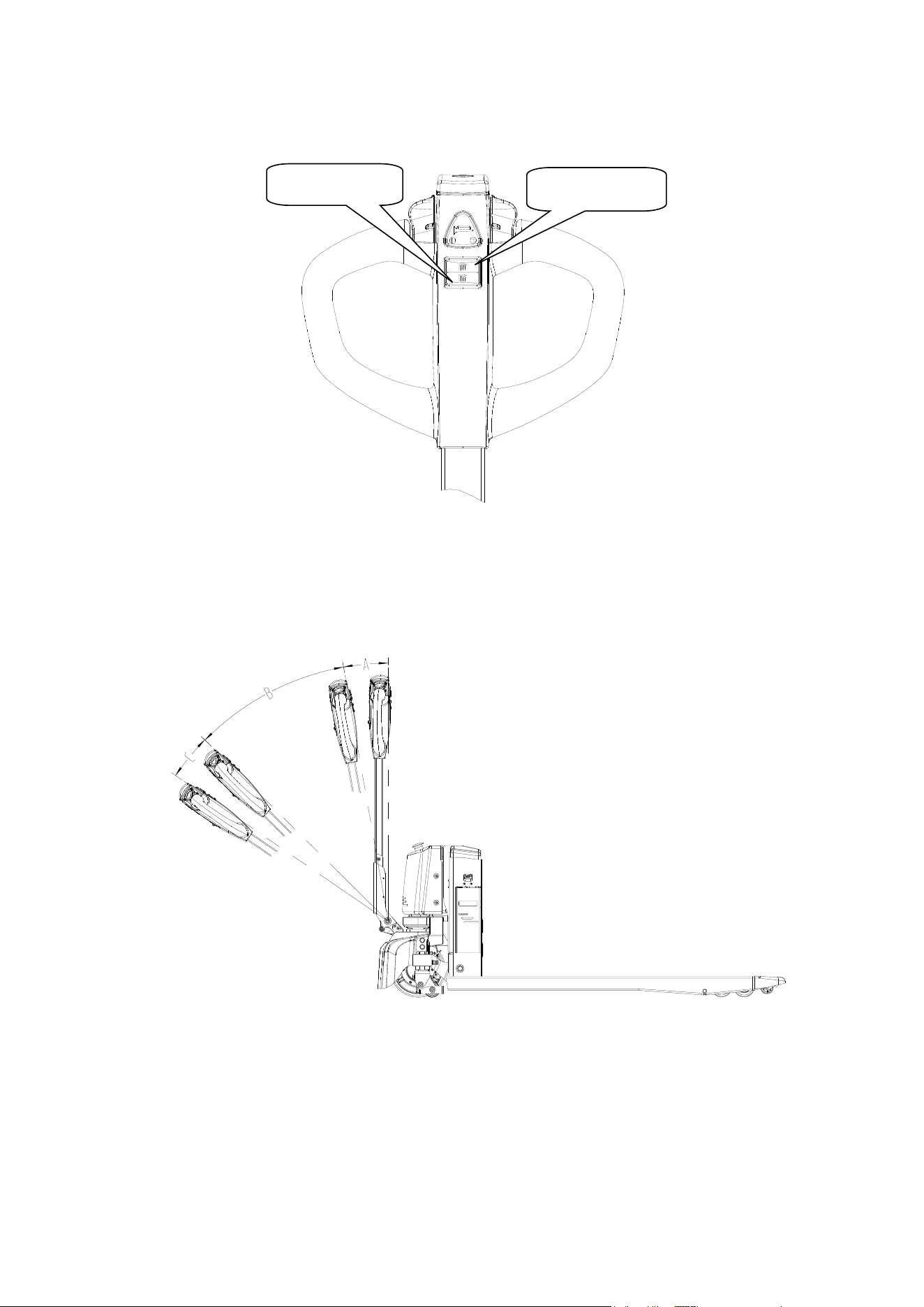
Fork lifting and lowering
- Lifting:Press the lifting button to lift
- Lowering:Press the lowering button to lower。
Figure 11
5.5 Traveling of the pallet truck
- Rotate the handle to the traveling zone:
A and C are the braking zones;
B is the traveling zone;
Figure 12
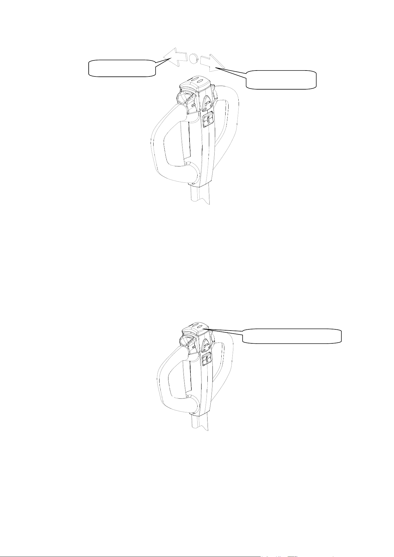
-Slowly rotate the accelerator to start. As shown in the figure, the rotation direction of the accelerator
knob is the driving direction. The rotation angle of the knob is proportional to the driving speed. Release
the accelerator knob and the knob will return to its original position automatically. At this time, the truck
will slow down slowly until it stops (For safety reasons, do not accelerate rapidly)
Lifting button
Lowering button
7
Figure 13
Braking
- When the accelerator is released during normal driving, the truck will slow down slowly until it stops,
and finally the brake will automatically lock and park.
- Turn the handle to A or C quickly for emergency braking (Figure 12); the brake will lock the wheel to
achieve an emergency braking.
Emergency reverse button
The emergency reverse button is at the end of the hand. When it’s touched by operator’s body, the truck
will stop traveling immediately, and then travel backwards for a distance. The function is set to minimize
possible squeeze injuries when the truck encounters into obstacles over its traveling.
Figure 14
5.8 Parking
- Release the accelerator to stop the truck. The truck stops slowly until the brake engages and parks
- Lower the fork to the lowest position.
- Turn off the key switch.
- Disconnect the battery harness in order to park for a long time.
Emergency reverse button
Travel forward
Travel backward

8
6. Use, maintenance and charging of storage battery
6.1 Battery maintenance
6.1.1 The battery type used is lithium ion battery, which is environment-friendly, free of chemical mercury,
cadmium and other components.
6.1.2 Precautions
◆ Working ambient temperature of lithium battery is -10°C ~ 45°C.
◆ Charge and discharge the battery every 3 months when it is stored for a long time.
◆ Fully charge the battery before the first use or re-use after long-term idleness.
◆ Do not short circuit the battery, which may permanently damage it.
◆ Do not weld the battery by yourself.
◆ Do not keep the battery in an unfavorable environment, such as extreme temperature, deep cycle, or
often overcharge or over-discharge.
◆ Do not touch the hot battery until it cools down.
◆ Taking down the battery by holding the plug, instead of pulling the charging line.
◆ The battery may be hot after charging, cool it down in a ventilated environment.
◆ Do not put batteries in water or sea water;
◆ Do not try to separate, squeeze, or hit the battery. Battery lye is harmful to skin and eyes, and will
corrode clothes.
◆ Keep the battery out of children’s reach.
6.2 Charging of battery
- When the battery indicator shows that the battery is low, charge it immediately, otherwise the
battery will be damaged.
- Turn off the cable lock and emergency stop switch, connect the charging cable to the charging socket,
and connect the plug to the power socket to start charging.
- When the charger indicator light is green, it indicates that the battery is fully charged. At this time,
you can unplug the connecting cable.
6.3 Power display (magnetic lock)
- The green light is always ON: 78% - 100%
- Blue light is always ON: 52% - 77%
- Yellow light is always ON: 26% - 51%
- The red light is always ON: 16% - 25%
- Red light flashing: < 15%
When the red light is always on, please prepare to drive the truck to the charging place for charging;
The red light flashes as a warning, indicating that the truck is about to stop working. Please charge the
battery immediately. If it is used continuously, the battery life will be seriously damaged.
6.4 Power display (password lock)
- The green light is always ON: >50%
- The yellow light is always ON: 20%-50%
- The red light is always ON:<20%
7. Maintenance
Whether a truck can be used satisfactorily depends on careful maintenance. Neglect of maintenance,
which may endanger personal safety and damage property. Therefore, checks should be made regularly,
abnormal phenomena should be eliminated in time, and faulty cars should not be used to ensure safety
and prolong the service life of cars.
Maintenance of this pallet truck is generally divided into three levels: daily maintenance, weekly
9
maintenance and Periodic Maintenance.
Daily maintenance:To keep the surface clean and examine if the power supply cable is damaged.
Weekly Maintenance: To check the condition of the operational components, all fastening items, if
oil leakage, if abnormal wearing in mechanical components exists, if
abnormal temperature rises or sparks in electric equipment, etc.
Periodic Maintenance
a) Mechanical maintenance:do it every 6 months. Main content is to check whether the fasteners
are loose, whether the wheels work flexibly and whether the fork lifts normally. The running
noise of the truck after maintenance is not more than 75 dB.
b) Hydraulic maintenance:do it yearly to check whether the cylinder is in normal condition,
whether there are internal and external leakage. Whether the hydraulic oil is clean or not, which
is usually replaced once in 12 months. Hydraulic oil adopts ISO standard. L-HV32 and L-HV15
cryogenic hydraulic oils are used when the ambient temperature is -41-104℉ and -50-41℉
respectively. The waste oil replaced shall be treated in accordance with the relevant local laws
and regulations. Check whether the limit valve is working properly
c) Electrical Maintenance: do it every 3 months to check whether the electrical connectors are
reliable, whether the switches are normal, and check whether the electrical insulation is normal
(the insulation resistance between the electrical part and the car body should be greater than
0.5MΩ).
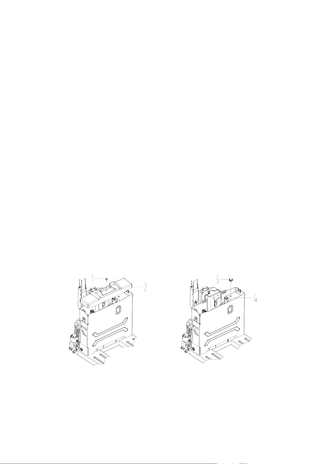
7.1 Adding hydraulic oil
Add hydraulic oil as shown in Figure 15 as follows:
⚫ First close the electric lock and emergency stop switch, and operate when power off;
⚫ Remove the screw 1 and take out the cover 2;
⚫ Remove the oil tank cap 3, add an appropriate amount of hydraulic oil into the oil filler, and the liquid
level must reach 60% of the oil tank 4 (the oil tank is made of white plastic, and the liquid level can
be observed externally).
Figure 15
10
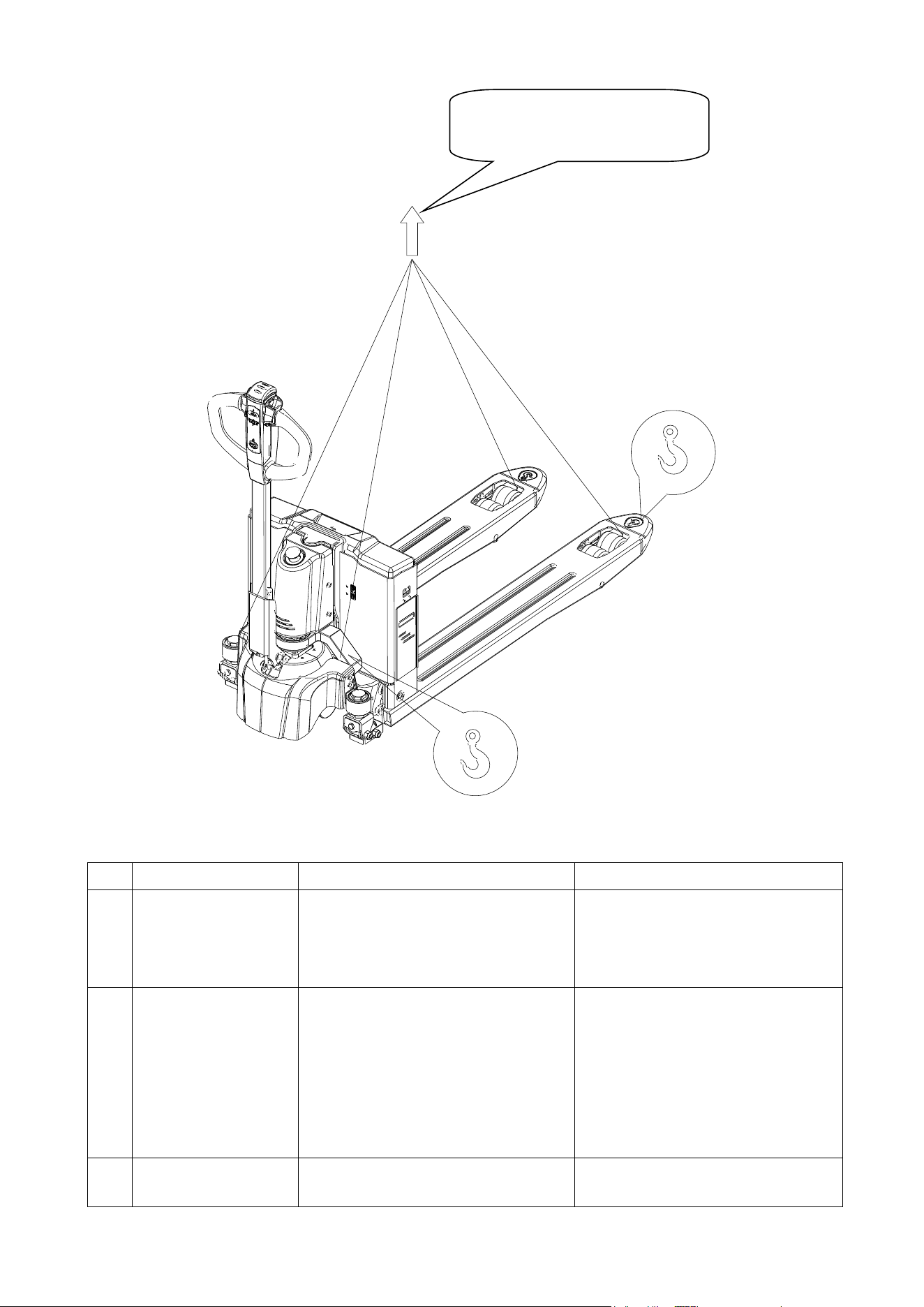
8. Truck hoisting
9. Trouble shooting
The table below provides some common failures of the truck in operation and the trouble shooting
No.
Fault
Cause analysis
Troubleshooting
1
Hydraulic oil leakage
1. Seal failure;
2. The surface of some parts is
slightly damaged or worn;
3. The joint is loose;
1. Replace the seal;
2. Replace the damaged parts;
3. Re tighten the loose parts;
2
Fork lifting failure
1. The viscosity of working oil is
too large or the working oil is
not injected;
2. There are impurities in the oil;
3. The motor pump is damaged;
1. Change the working oil;
2. Remove the impurities in the
oil circuit and renew the
working oil;
3. Replace the hydraulic pump
unit;
4. Readjust the relief valve value.
3
Fork lowering failure
1. The manual lowering solenoid
valve is stuck or damaged.
1. Replace the solenoid valve
Fasten the truck as shown in the fig
to hoist it.

11
No.
Fault
Cause analysis
Troubleshooting
4
Lifting motor failure
1. The power supply is not turned
on;
2. The battery has been
completely discharged;
3. Motor damage;
4. The fuse is blown;
1. Turn on the power supply;
2. Charge;
3. Check whether the travel
switch on the handle is
pressed down due to collision
and whether the brake is
damaged;
4. Replace the fuse;
5
Charging failure
1. Charger is damaged
2. Battery is damaged
3. Wiring failure
1. Replace a charger
2. Replace a battery
3. Check the charging wiring
10. Waste treatment
The abandoned batteries and hydraulic oil should not be placed carelessly and must be treated
according to the relevant local regulations and laws. Attention must be paid to environmental protection.
11. Accessories and spare parts
No.
Name
Application site
Specification
Qty(pc)
Remarks
1
Key
To the lock
2
2
Charger
Charge the battery
1
12
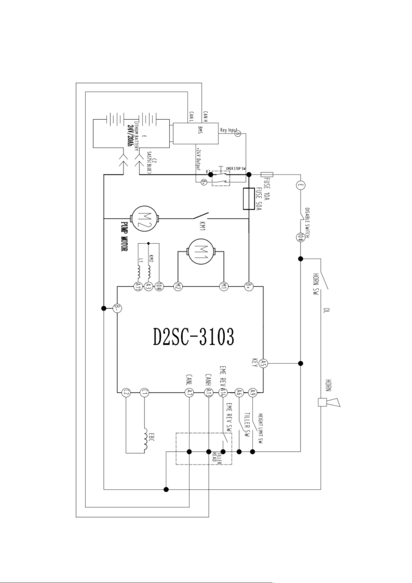
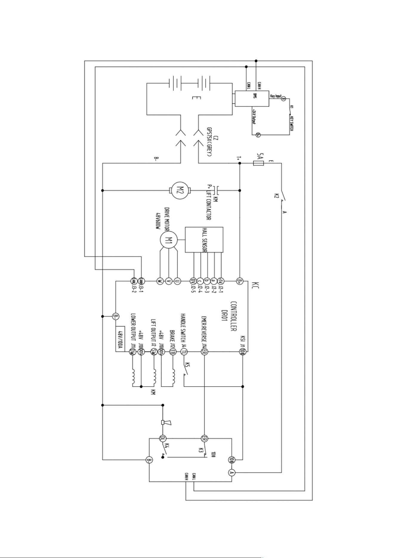
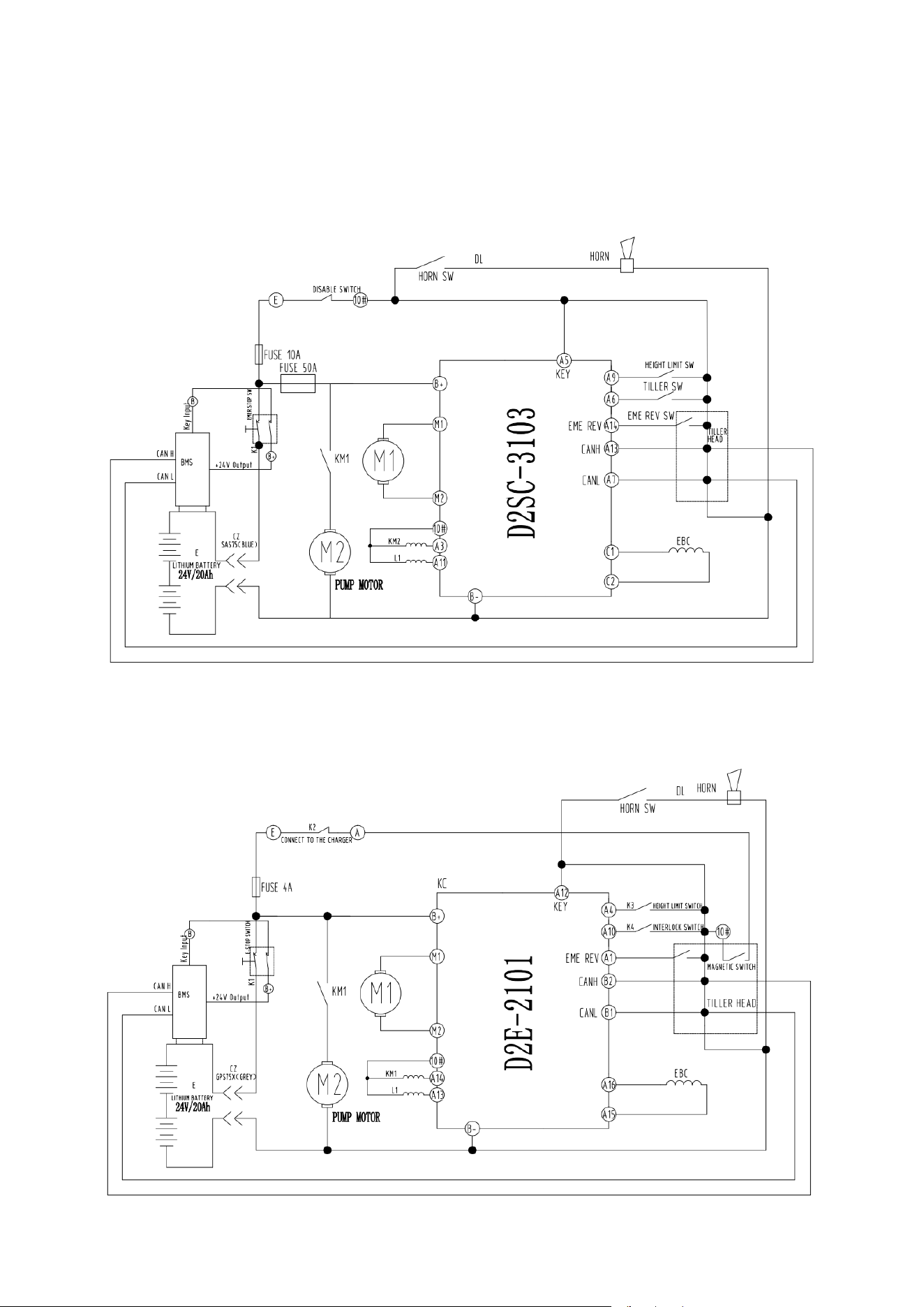
12. Electrical schematic diagram and fault code
12.1 Model with magnetic lock (1.5T)

13
12.1.2 Fault code table
Fault English
Fault code
Hardware Fault
42
Current Sense Fault
41
Precharge Fault
33
Brake On Fault
32
Battery Disconnect Fault
45
Parameter Fault
43
Brake Off Fault
34
Main Relay DNC
21
Wiring Falut
31
Main Driver Fault
23
Main Relay Welded
24
Throttle Fault
12
HPD Fault
35
EMR Sequencing Fault
22
Overvoltage Cutback
15
Undervoltage Cutback
14
Controller Overtemp Cutback
11
Pump SRO Fault
25
Creep Mode Fault
26
SRO Fault
27
Software Fault
36
Motor Temp Hot Cutback
44
Motor Overtemperature
46
Low BDI
51
Controller Overcurrent
52
Controller Severe Overtemp
53
Controller Undertemp Cutback
54
Parameter Change Fault
55
Severe Overvoltage
56
Motor Short
61
Motor Open
62
Gage PDO Timeout
63
PDO Timeout
64
BMS PDO Timeout
65
Driver 1 On Fault
66
Driver 2 On Fault
67
Driver 1 Off Fault
71
Driver 2 Off Fault
72
Severe Undervoltage
29
14
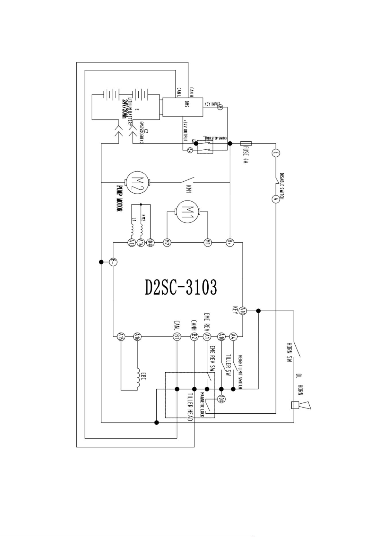
12.2 EURO type(1.5T)
12.2.1 Electrical schematic diagram
12.2.2 Fault code table
See 12.1.2
15
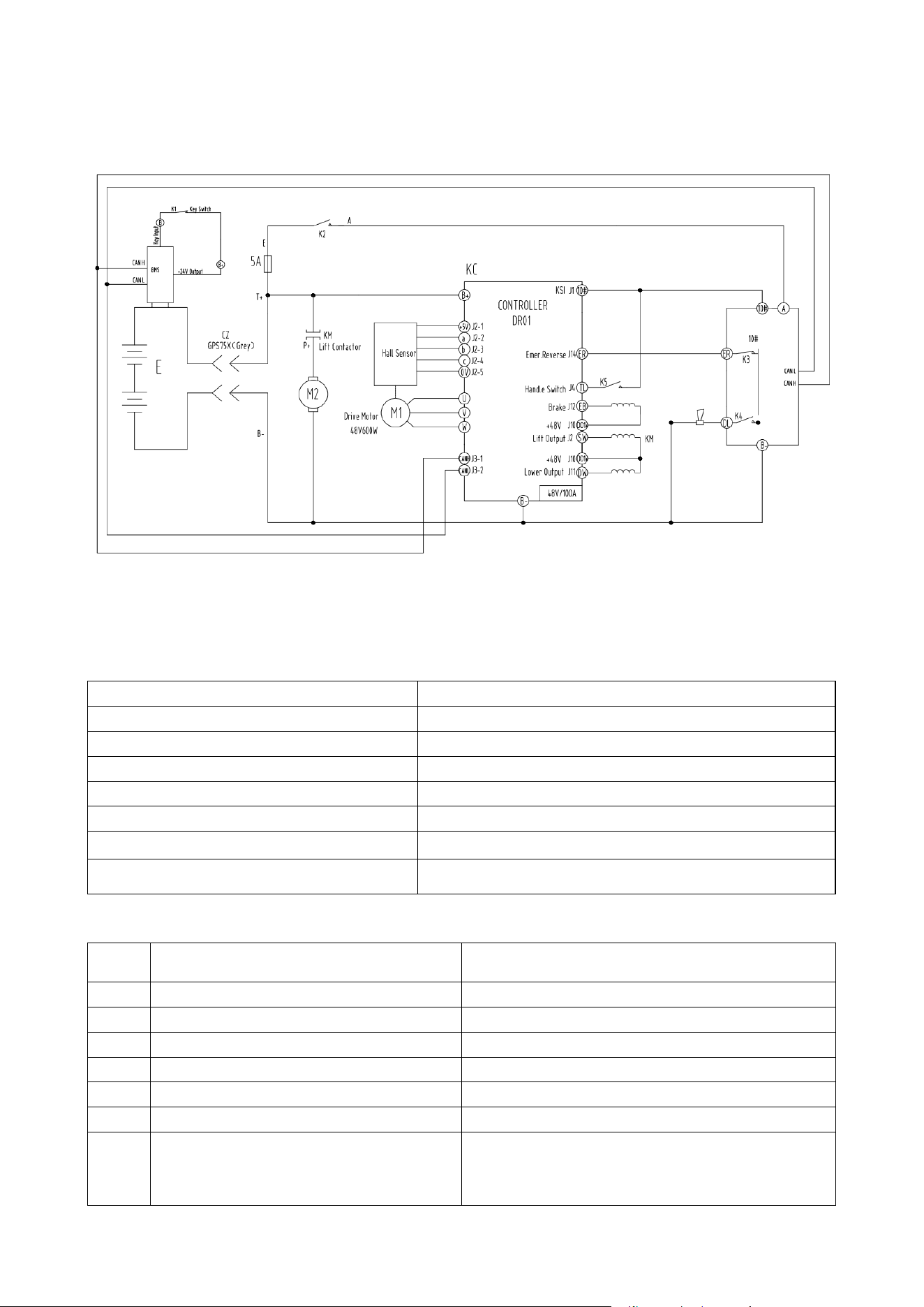
12.3 EURO type (2T)
12.3.1 Electrical schematic diagram

16
12.3.2 Fault code table
Fault
code
Fault type
Possible causes
Trouble shooting
1
Power unit protection
1. The motor is locked;
2. The internal wiring of the
motor is loose;
3. Abnormal operating
conditions
◆ Whether the motor is stuck;
◆Contact the agent or manufacturer;
◆ Manual power on/off reset
2
Acceleration overcurrent
1. The acceleration curve is
too steep;
2. The load is too large;
◆ Check the acceleration and
deceleration time;
◆ Eliminate the cause of excessive load;
◆ Re learn the motor position;
Manual power on/off reset
3
Deceleration overcurrent
1. The deceleration curve is
too steep;
2. The load is too large;
4
Constant speed
overcurrent
1. The load is too large;
5
Accelerating overvoltage
1. The input voltage is too
high;
2. The acceleration curve is
too steep;
◆ Adjust the input voltage; ◆ Check the
acceleration and deceleration time;
Manual power on/off reset
6
Deceleration overvoltage
1. The input voltage is too
high;
2. The deceleration curve is
too steep;
7
Constant speed
overvoltage
1. The input voltage is too
high;
9
Undervoltage fault
1. Instantaneous power
failure of input power
supply;
2. The input voltage is too
low;
3. The power cord is too
thin;
◆ Eliminate external power supply
problems; Check whether the power
supply is disconnected during operation
and whether the power cord is thick
enough;
◆ Adjust the input voltage;
Manual power on/off reset
12
Motor overload
1. Improper parameter
setting;
2. Excessive load;
◆ Adjust parameters;
◆ Reduce the load;
◆ Re learn the motor position;
Manual power on/off reset
13
Motor phase loss
1. The internal wiring of
the motor is loose;
2. The motor is damaged;
◆ Check the motor for internal damage
caused by external force;
Manual power on/off reset
14
Drive overtemperature
fault
1. Drive temperature too
high
◆ Heat dissipation instrument (electric
fan, etc.) can be added when the
temperature drops before operation
Manual power on/off reset
23
Parameter setting fault
1. Parameter setting error;
◆ Set parameters correctly;
Manual power on/off reset

17
24
Bus charging fault
1. Charging circuit fault
◆ Please contact the agent or
manufacturer
25
Memory failure
1. Motor storage data is
abnormal;
◆ Please contact the agent or
manufacturer;
Manual power on/off reset
26
Motor locked
1. Motor locked;
◆ Check the load;
Manual power on/off reset
27
Motor reverse
1. Excessive reverse load;
◆ Check the load;
Manual power on/off reset
28
Motor out of step
1. Acceleration time is too
fast;
◆ Check the acceleration and
deceleration time;
Manual power on/off reset
29
Velocity loop saturation
1. Excessive load;
2. The speed setting is too
large;
◆ Reduce the load;
◆ Check the set speed;
Manual power on/off reset
30
IF startup failed
1. Drive loop fault
◆ Please contact the agent or
manufacturer;
Manual power on/off reset
36
Hall sensor fault, not
between 1 and 6
1. Hall sensor fault inside the
motor;
2. Hall detection loop fault
◆ Check whether the Hall level jump
inside the motor is normal;
◆ Please contact the agent or
manufacturer;
Manual power on/off reset
37
Hall sensor fault, phase
sequence error, current 1
1. Hall sensor fault inside the
motor;
2. Hall detection loop fault
◆ Check whether the Hall level jump
inside the motor is normal;
◆ Please contact the agent or
manufacturer;
Manual power on/off reset
38
Hall sensor fault, phase
sequence error, current 2
1. Hall sensor fault inside the
motor;
2. Hall detection loop fault
◆ Check whether the Hall level jump
inside the motor is normal;
◆ Please contact the agent or
manufacturer;
Manual power on/off reset
39
Hall sensor fault, phase
sequence error, current 3
1. Hall sensor fault inside the
motor;
2. Hall detection loop fault
◆ Check whether the Hall level jump
inside the motor is normal;
◆ Please contact the agent or
manufacturer;
Manual power on/off reset
40
Hall sensor fault, phase
sequence error, current 4
1. Hall sensor fault inside the
motor;
2. Hall detection loop fault
◆ Check whether the Hall level jump
inside the motor is normal;
◆ Please contact the agent or
manufacturer;
Manual power on/off reset

18
41
Hall sensor fault, phase
sequence error, current 5
1. Hall sensor fault inside the
motor;
2. Hall detection loop fault
◆ Check whether the Hall level jump
inside the motor is normal;
◆ Please contact the agent or
manufacturer;
Manual power on/off reset
42
Hall sensor fault, phase
sequence error, current 6
1. Hall sensor fault inside the
motor;
2. Hall detection loop fault
◆ Check whether the Hall level jump
inside the motor is normal;
◆ Please contact the agent or
manufacturer;
Manual power on/off reset
43
hall sensor fault, the
phase sequence
obtained by CAP is the
same for two
consecutive times
1. Hall sensor fault inside the
motor;
2. Hall detection loop fault
◆ Check whether the Hall level jump
inside the motor is normal;
◆ Please contact the agent or
manufacturer;
Manual power on/off reset
44
Entering CAP, the interval
time is too small
1. Hall sensor fault inside the
motor;
2. Caused by interference
signal
3. Hall detection loop fault
◆ Check whether the Hall level jump
inside the motor is normal;
◆ Please contact the agent or
manufacturer;
Manual power on/off reset
45
Incoming CAP interrupt,
non four channel capture
signal exception
1. Hall sensor fault inside the
motor;
2. Hall detection loop fault
◆ Check whether the Hall level jump
inside the motor is normal;
◆ Please contact the agent or
manufacturer;
Manual power on/off reset
47
Band brake load
detection fault
1. Band brake circuit is
open;
2. Holding brake circuit is
short circuited
◆ Check whether the band brake load
has been connected;
◆ Please contact the agent or
manufacturer;
Manual power on/off reset
48
Pump load detection
fault
1. Open circuit of lifting
pump circuit
2. The circuit of lifting pump
is short circuited
◆ Check whether the lifting pump load
has been connected;
◆ Please contact the agent or
manufacturer;
Manual power on/off reset
49
Valve load detection fault
1. The circuit of the lowering
valve is open
2. The circuit of lowering
valve is short circuited
◆ Check whether the lowering valve load
has been connected;
◆ Please contact the agent or
manufacturer;
Manual power on/off reset
50
Parameter mismatch
fault
1. Parameter configuration
conflict
◆ Check whether the parameter
configuration is correct;
◆ Please contact the agent or
manufacturer;
Manual power on/off reset

19
51
Precharge fault
1. The input voltage is too
low;
2. KSI voltage is pulled down
during use
Check whether the input voltage is
reasonable;
◆ Check whether KSI voltage is pulled
down during use;
◆ Please contact the agent or
manufacturer;
Manual power on/off reset
52
Holding brake speed
fault
1. The speed is higher than
the fault threshold under the
condition of holding brake;
◆ Check whether the holding brake force
is not enough to cause the slope to slide
down;
◆ Please contact the agent or
manufacturer;
Manual power on/off reset
53
Band brake output
detection fault
1. Band brake circuit is
open;
2. Holding brake circuit is
short circuited
◆ Check whether the band brake load
has been connected;
◆ Please contact the agent or
manufacturer;
Manual power on/off reset
54
Pump output detection
fault
1. Open circuit of lifting
pump circuit;
2. The circuit of lifting pump
is short circuited
◆ Check whether the lifting pump load
has been connected;
◆ Please contact the agent or
manufacturer;
Manual power on/off reset
55
Drop valve output
detection fault
1. The circuit of lowering
valve is open;
2. The circuit of lowering
valve is short circuited
◆ Check whether the lowering valve load
has been connected;
◆ Please contact the agent or
manufacturer;
Manual power on/off reset
56
The input voltage slave
of analog quantity 2
judges that the IO port is
incorrect
1. Analog quantity 2 input
circuit slave circuit open
circuit
2. Analog quantity 2 input
circuit slave circuit short
circuit
◆ Check whether the slave circuit of
analog quantity 2 input circuit is
abnormal;
◆ Please contact the agent or
manufacturer;
Manual power on/off reset
57
The lifting switch slave
judges that the IO port is
incorrect
1. Lift switch input circuit
slave circuit open circuit
2. The lift switch input circuit
is short circuited to the slave
circuit
◆ Check whether the slave circuit of the
lifting switch input circuit is abnormal;
◆ Please contact the agent or
manufacturer;
Manual power on/off reset
58
The forward switch slave
judges that the IO port is
incorrect
1. Forward switch input
circuit slave circuit open
circuit
2. The slave circuit of the
forward switch input circuit
is short circuited
◆ Whether the slave circuit of the
forward switch input circuit is abnormal;
◆ Please contact the agent or
manufacturer;
Manual power on/off reset

20
59
The mode switch slave
determines that the IO
port is incorrect
1. The mode switch input
circuit slave circuit is open
2. The mode switch input
circuit is short circuited to
the slave circuit
◆ Whether the mode switch input circuit
slave circuit is abnormal;
◆ Please contact the agent or
manufacturer;
Manual power on/off reset
60
The reverse switch slave
determines that the IO
port is incorrect
1. Reverse switch input
circuit slave circuit open
circuit
2. The reverse switch input
circuit is shorted to the slave
circuit
◆ Check whether the slave circuit of the
reverse switch input circuit is abnormal;
◆ Please contact the agent or
manufacturer;
Manual power on/off reset
61
The input voltage slave
of analog quantity 1
judges that the IO port is
incorrect
1. Analog quantity 1 input
circuit slave circuit open
circuit
2. Analog quantity 1 input
circuit slave circuit short
circuit
◆ Check whether the slave circuit of
analog quantity 1 input circuit is
abnormal;
◆ Please contact the agent or
manufacturer;
Manual power on/off reset
62
The interlocking switch
slave judges that the IO
port is incorrect
1. Interlock switch input
circuit slave circuit open
circuit
2. Interlock switch input
circuit slave circuit short
circuit
◆ Whether the slave circuit of the
interlock switch input circuit is abnormal;
◆ Please contact the agent or
manufacturer;
Manual power on/off reset
63
The emergency reverse
switch slave judges that
the IO port is incorrect
1. The slave circuit of the
emergency reverse switch
input circuit is open
2. The slave circuit of the
emergency reverse switch
input circuit is short circuited
◆ Whether the slave circuit of the
emergency reverse switch input circuit is
abnormal;
◆ Please contact the agent or
manufacturer;
Manual power on/off reset
64
Slave communication
failure
1. Slave MCU is abnormal;
2. Communication circuit
fault between MCU
◆ Please contact the agent or
manufacturer;
Manual power on/off reset
65
Third level fault of slave
1. The control of the main
MCU is out of control, and
the emergency response
from the MCU
◆ Please contact the agent or
manufacturer;
Manual power on/off reset
66
The slave judges that the
speed is too high
1. The speed is out of
control and exceeds the
maximum speed by 20%
◆ Please contact the agent or
manufacturer;
Manual power on/off reset
67
Abnormal internal 5V
voltage
1. Internal 5V voltage
fluctuation
2. Internal 5V fault threshold
parameter setting error
◆ Check whether the parameter settings
are correct
◆ Please contact the agent or
manufacturer;
Manual power on/off reset

21
68
Abnormal internal 15V
voltage
1. Internal 15V voltage
fluctuation
2. Internal 15V fault
threshold parameter setting
error
◆ Check whether the parameter settings
are correct
◆ Please contact the agent or
manufacturer;
Manual power on/off reset
69
Abnormal external 5V
voltage
1. External 5V voltage
fluctuation
2. External 5V fault
threshold parameter setting
error
◆ Check whether the parameter settings
are correct
◆ Please contact the agent or
manufacturer;
Manual power on/off reset
70
Communication failure
between main controller
and battery
1. Battery BMS is abnormal;
2. The communication line
between the main controller
and the battery is
disconnected
◆ Check whether the harness is
complete
◆ Please contact the agent or
manufacturer;
Manual power on/off reset
71
Lithium battery
overvoltage fault
1. Overvoltage caused by
lithium battery charging 2.
Voltage rise caused by
controller braking when the
battery is fully charged
◆ Check whether the lithium battery has
been charged with overvoltage
◆ Please contact the agent or
manufacturer;
Manual power on/off reset
73
Lithium battery serious
failure
1. The battery BMS detects a
serious fault. 2. The battery
is extremely low
◆ Check the lithium battery for serious
failure
◆ Check whether the battery power is
extremely low;
Manual power on/off reset
74
Low battery warning
1. Low battery warning
◆ Check whether the battery power is
low;
Replace the battery
75
Drive overvoltage
protection fault
1. Instantaneous bus
voltage is too high
◆ Check whether there is a working
condition that causes the bus voltage to
rise rapidly during use;
Manual power on/off reset
76
Master slave MCU
communication fault
1. Communication failure of
master and slave MCU
2. Communication circuit
fault between MCU
◆ Please contact the agent or
manufacturer;
Manual power on/off reset
77
Hall signal loss from MCU
1. Open circuit from MCU
Hall circuit
◆ Please contact the agent or
manufacturer;
Manual power on/off reset
80
The power on self-test
interlock switch is not
reset
1. Interlock switch is not
reset
Reset all switches

22
81
Power on self-test
forward switch not reset
1. The forward switch is not
reset
Reset all switches
82
The power on self-test
backward switch is not
reset
1. The back switch is not
reset
Reset all switches
83
The power on self-test
throttle switch is not
reset
1. Throttle switch is not
reset
Reset all switches
84
The emergency switch of
power on self-test is not
reset
1. Emergency switch is not
reset
Reset all switches
85
Power on self-test lifting
switch not reset
1. The lifting switch is not
reset
Reset all switches
86
The power on self-test
lowering valve switch is
not reset
1. The lowering valve switch
is not reset
Reset all switches
87
Control signal timing
failure
1. Operation sequence error
Reset all switches
88
Direction key failure
1. Both forward and
backward are effective
Reset all switches
89
Emergency reverse
warning
1. Triggered after
emergency reverse stop
Reset all switches
90
Sequence failure
1. Operation sequence error
Reset all switches

23
13. Packing list
Packing list
Consignee: Ex-work No:
Contract No.: Ex-work Date:
No.
Product Name
QTY
Net.
Weight
(lbs)
Dimension
(L×W×H)
Remarks
1
Pallet truck
1
A complete set
2
Accessory box
1
Technical documents,
accessories and spare
parts.
Note:1.The following documents are in the file bag:
a) Operation manual 1 volume
b) Parts catalogue 1 volume
c) Qualification certificate 1 copy
d) Packing list 1 copy
2.Accessories and spare parts
No.
Name
Application site
Specification
Qty(pc)
Remarks
1
Key
To the lock
2
2
Charger
Charge the battery
1
Consignor:


Contents
1. Structure .......................................................................................................................................................... 1
1.1 Housing disassembly ..................................................................................................................... 2
1.2 Detailed structure ............................................................................................................................. 3
2. Mechanical structure ................................................................................................................................... 4
2.1 Brake disassembly................................................................................................................................. 4
2.2 Braking shaft sleeve disassembly.................................................................................................... 4
2.3 Motor disassembly ................................................................................................................................ 5
2.4 Wheel disassembly ................................................................................................................................ 6
2.5 Hydraulic station disassembly .......................................................................................................... 6
2.6 Handle disassembly .............................................................................................................................. 7
2.7 Connecting rod adjustment ............................................................................................................... 7
2.8 Fork roller disassembly ....................................................................................................................... 8
2.9 Cylinder disassembly ............................................................................................................................ 8
2.10 Driving wheel disassembly .............................................................................................................. 9
3. Hydraulic system ......................................................................................................................................... 10
3.1 Hydraulic schematic diagram .......................................................................................................... 10
3.2 Cylinder seals replacement .............................................................................................................. 10
3.3 System pressure adjustment ........................................................................................................... 11
3.4 Add the hydraulic oil ............................................................................................................................ 11
3.5 Lubricating oil specification and required amount .................................................................. 11
4. Electric system ............................................................................................................................................. 12
4.1 Electric system diagram .................................................................................................................... 12
4.2 Electrical schematic diagram .......................................................................................................... 13
4.3 Electrical components ........................................................................................................................ 14
Service Manual
1
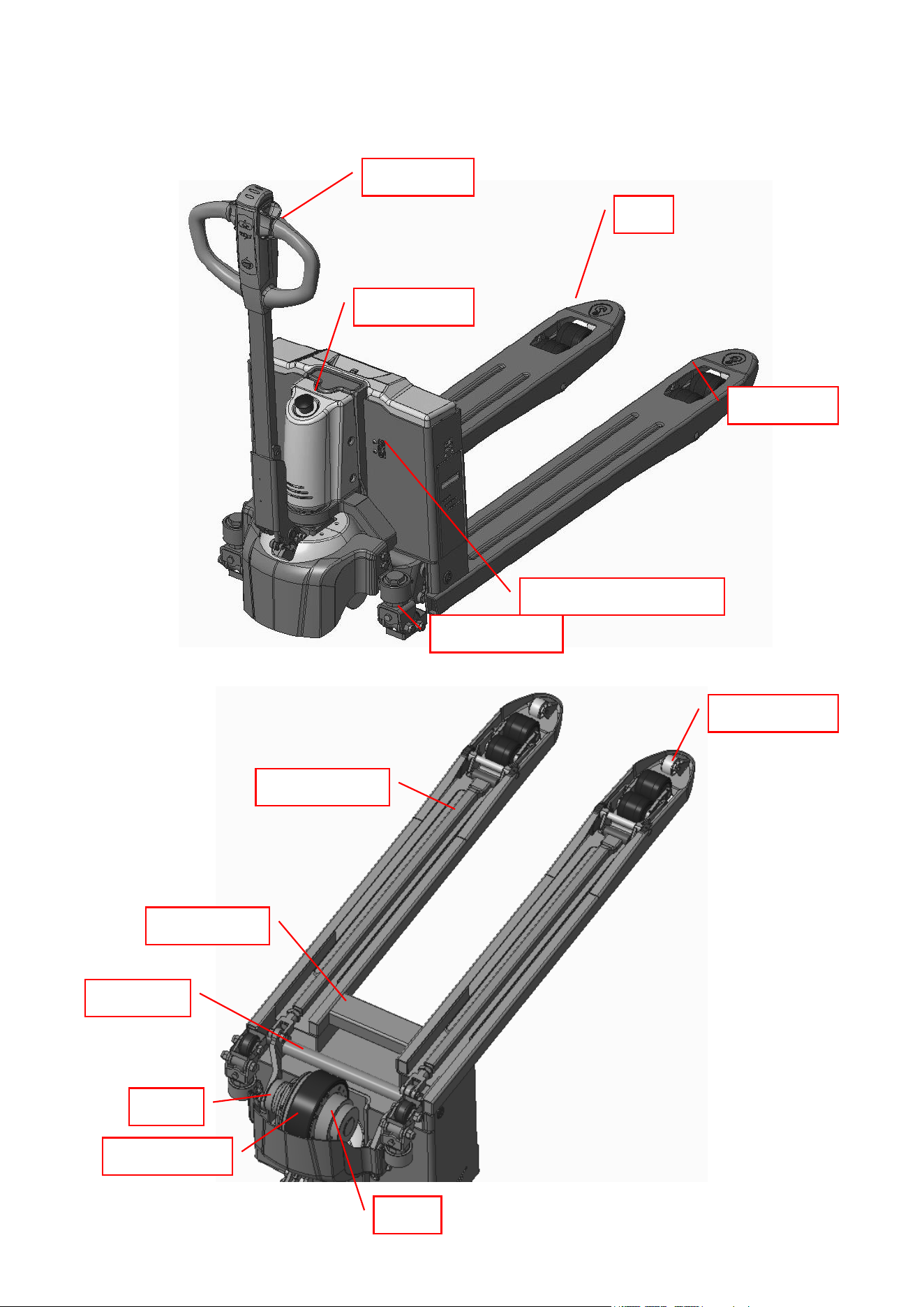
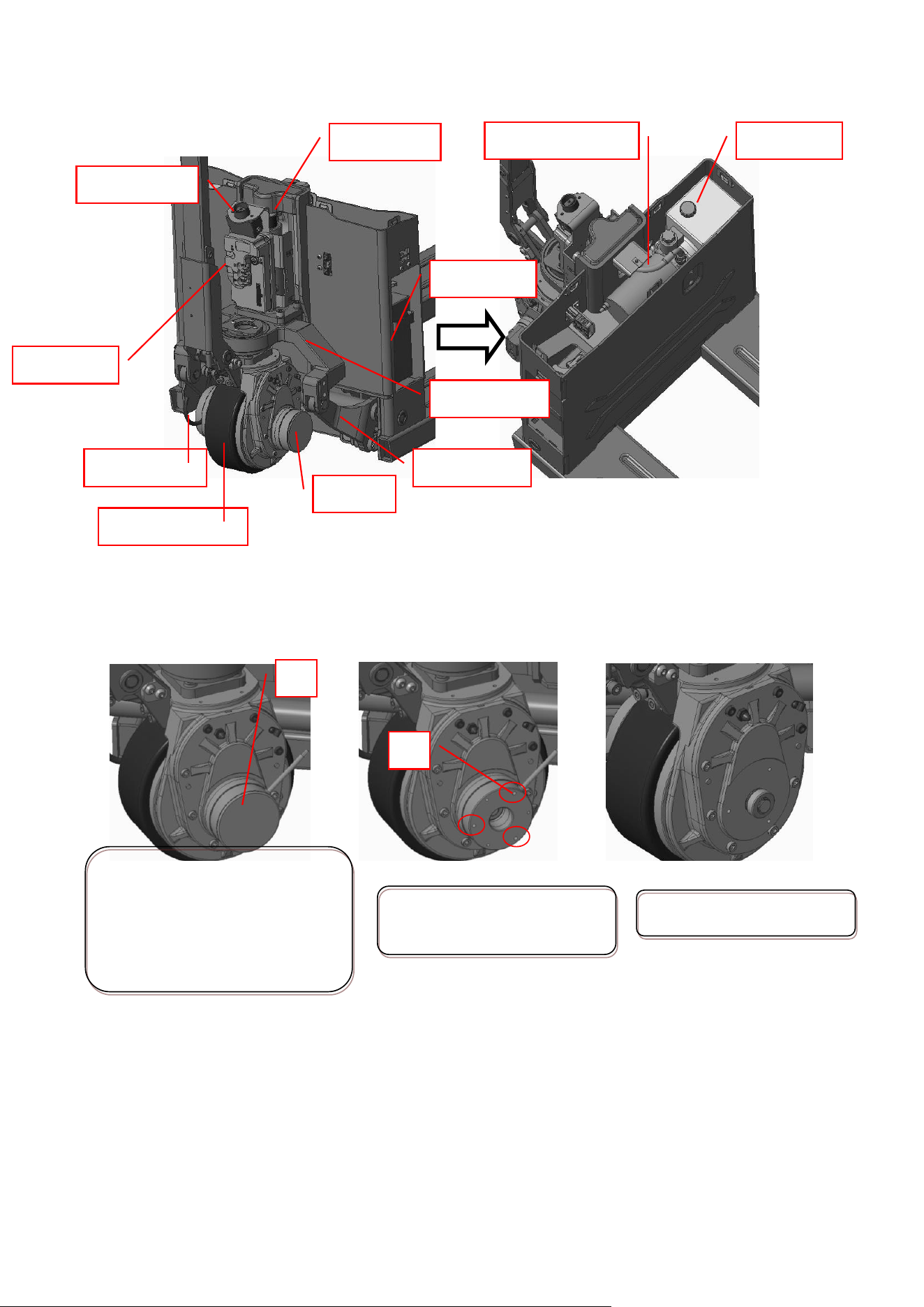
1. Structure
Tiller head
Guiding roller
E-stop switch
Balance wheel
Truck frame
Fork roller
External charging port
Connecting rod
Driving wheel
Fork
Brake
Motor
Rocker arm
2
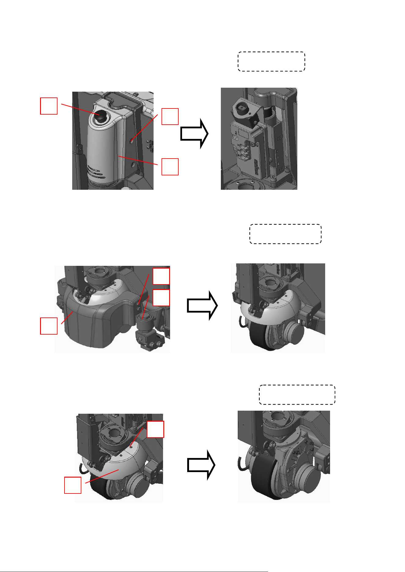
1.1 Housing disassembly
1.1.1 Front housing disassembly
① Remove the red E-stop switch cover 1 by pressing it down and rotate 90°counterclockwise;
② Unscrew part 2, 4 pieces in all;
③ Remove the front housing assembly 3.
1.1.2 Rear housing and balance wheel disassembly
① Unscrew part 1, 4 pieces in all;
② Remove the rear housing 2 and the balance wheel assembly 3.
1.1.3 Front and rear plastic cover disassembly
① Unscrew part 1, 4 pieces in all;
② Turn the steering gear 90°to take out the covers.
1
2
After disassembly
1
2
After disassembly
1
2
After disassembly
3
3
3
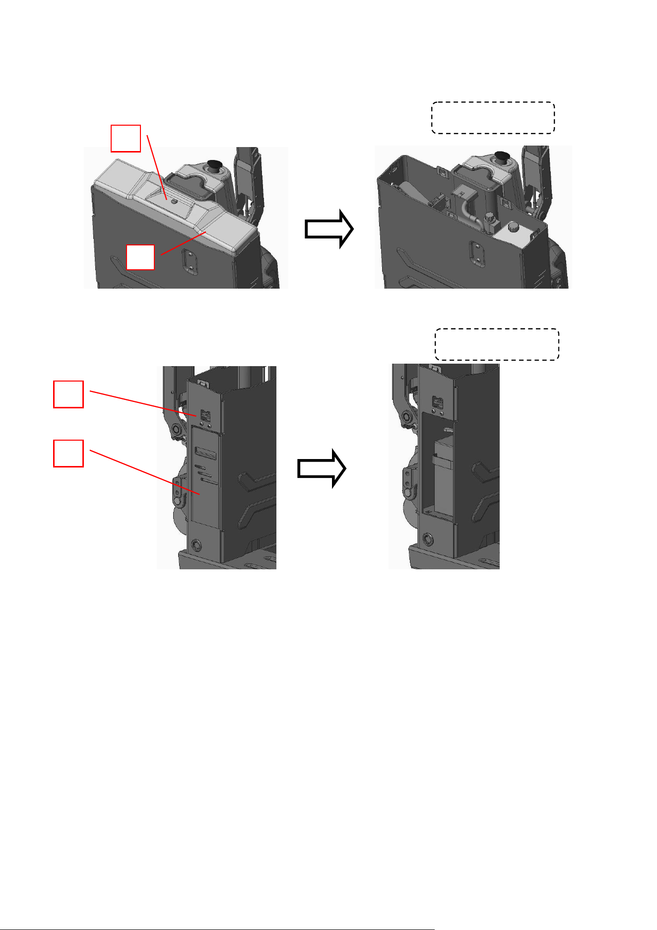
1.1.4 Upper housing disassembly
① Unscrew part 1, 1 piece in all;
② Remove the upper housing 2.
1.1.5 Battery compartment cover plate disassembly
① Pull the lock 1 upward
② Remove the battery compartment cover plate 2.
1.2 Detailed structure
1
2
After disassembly
1
2
After disassembly
4
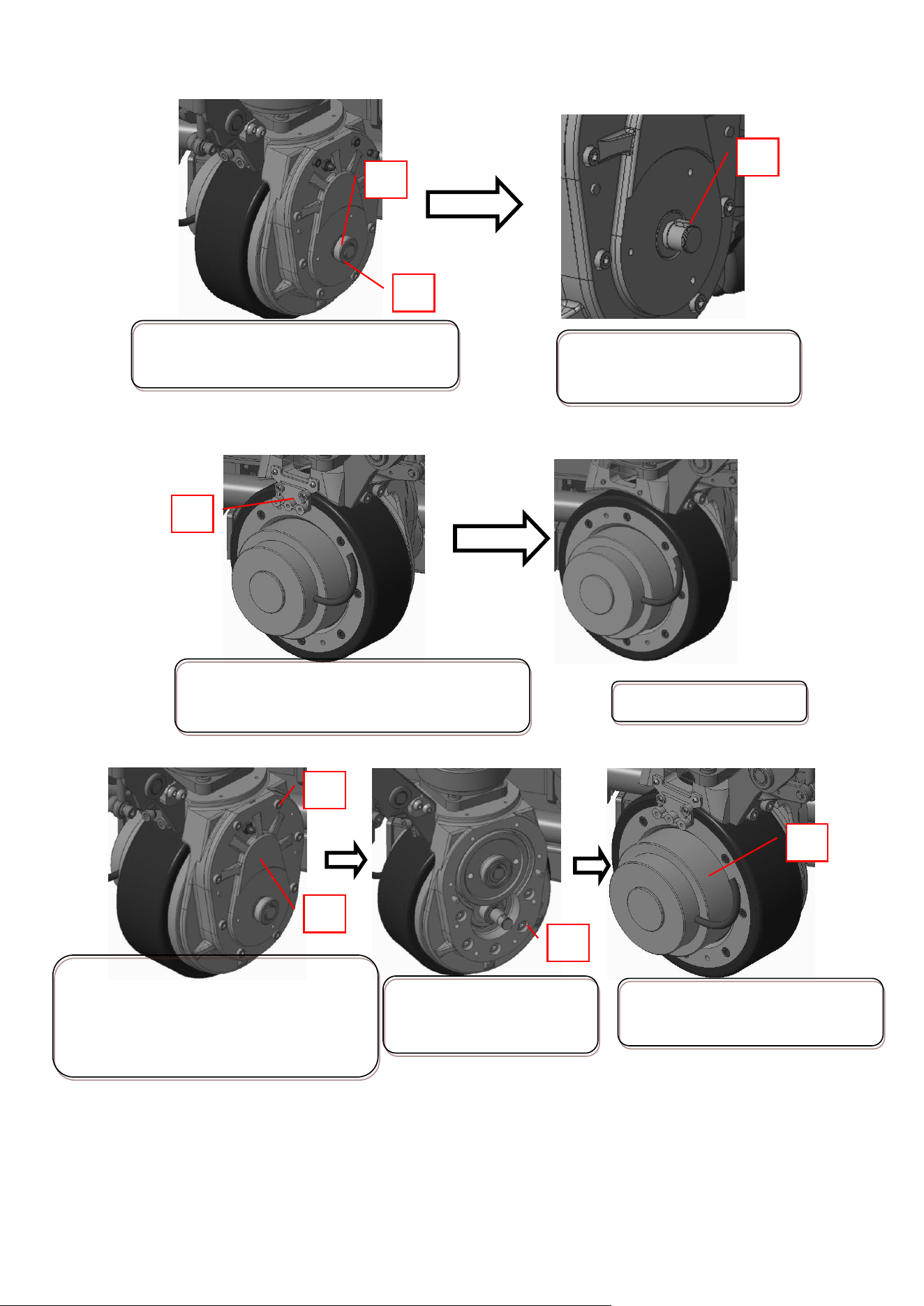
2. Mechanical structure
2.1 Brake disassembly
2.2 Braking shaft sleeve disassembly
Replace the shaft sleeve together with the brake. The braking shaft sleeve is included in the braking
parts package.
Oil tank
Disassemble the plastic cover 1
of the brake by disconnecting
the power supply and the
braking harness, and turning
the steering gear right 90°
1
Unscrew the braking screw 2,
3 pieces in all
After brake disassembly
Lifting motor
Cylinder
E-stop switch
Controller
Driving system
Brake
Driving motor
Rocker arm
Support seat
2
Battery
5
2.3 Motor disassembly
Disconnect the power first, then disassemble the motor(2.1) and the braking shaft sleeve(2.2)
1
3
Remove the spring circlip 1 and the shaft
sleeve 2
2
2
3
5
Unscrew the end cap screw 2 of the gear
box, 8 pieces in all by turning the
steering gear 90°,then remove the end
cap 3.
Take out the motor-wheel
assembly 5
Remove the flat key 3, and
keep it properly.
4
Unscrew the motor screw
4, 5 pieces in all
Disconnect the motor electric wiring and the
terminal block 1.
1
After disassembly
6
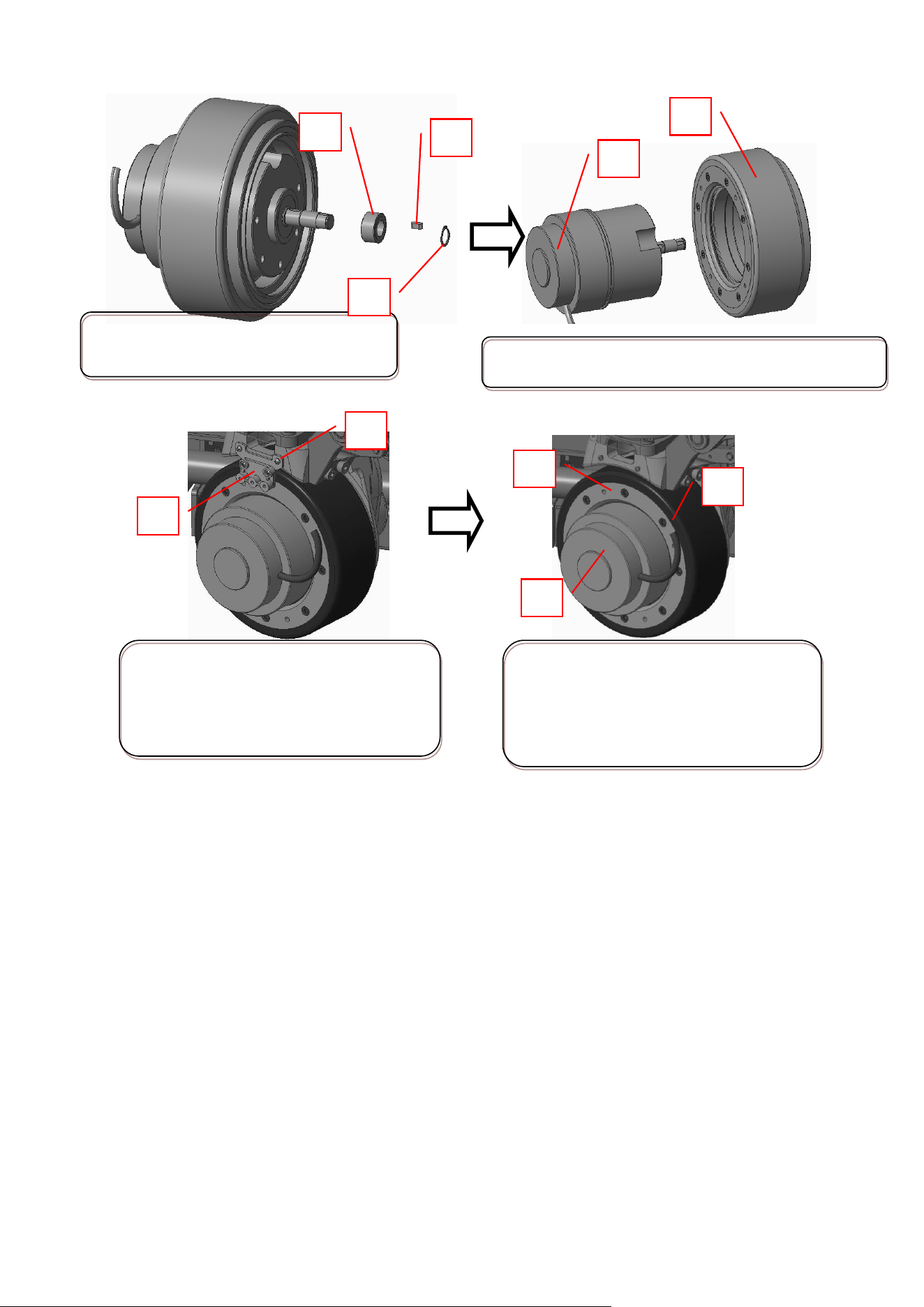
2.4 Wheel disassembly
2.5 Hydraulic station disassembly
Disassemble the hydraulic station after disconnecting the power supply, electric wiring and removing
the upper housing.
Remove the retaining ring 6, gear 7, flat
key 8 at the end of the motor shaft
6
8
7
Separate the motor 9 and the wheel assembly 10
9
10
Unscrew part 1 and remove the
terminal block by turning the steering
gear left 90°and disconnecting the
motor harness
1
2
Keep on unscrewing the fixing screw 3,
8 piece in all; then screw a M6 screw(>
30mm) into the hole 4 to remove the
wheel 5.
3
4
5
7
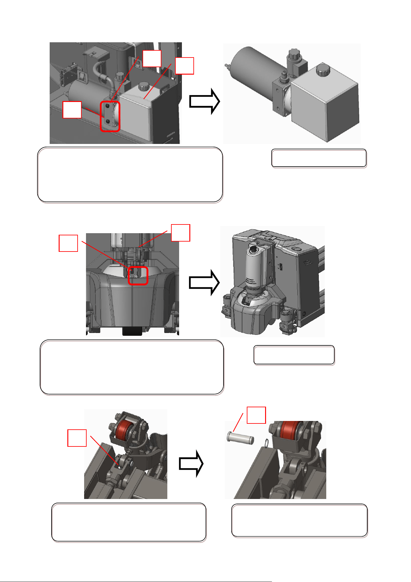
2.6 Handle disassembly
2.7 Connecting rod adjustment
1
Remove the retaining ring 1 at the hinge
point between the connecting rod and the
rocker arm.
2
Take out the pin shaft 2 from the
mounting hole
1
Lower the fork to the minimum height and remove
the high pressure hose 1. Be careful to collect the oil
flows from the pump oil tank now. Then unscrew the
fixing screw 2 to remove the hydraulic station 3.
2
3
The hydraulic station
1
2
After disassembly
Disconnect the power supply, the connector between
the handle and the truck frame;
unscrew part 1, 3 pieces in all;
Remove the handle assembly 2.
8
2.8 Fork roller disassembly
2.9 Cylinder disassembly
3
Reduce the connecting rod length clockwise by
loosening nut 3 and rotating joint 4
5
6
After a proper adjustment, the lift and
lower shall be smooth, and the clearance
between the wheel carriage limit point 5
and the surface under the fork 6 shall be
>1mm
1
Remove the spring pin 1, 2
pieces in all.
Take out pin shaft 2
2
Remove the roller 3. Disassembly
methods are almost the same for
single roller and double rollers.
3
4
Unscrew part 1 to remove the
controller 2.
1
2
Unscrew part 3 to remove
the support frame assembly
4
3
4
Unscrew part 5 and oil pipe
joint 6.Clean if there is oil
out.
5
6
9
2.10 Driving wheel disassembly
Remove the cylinder assembly 11
Separate the piston rod 8 from the truck
frame by lifting the truck frame 7. Place a
block 9 under the truck frame, and unscrew
part 10, 4 pieces in all.
7
9
8
11
10
1
2
Unscrew part 1, 4 pieces in all, and
remove the platen 2.
3
Take away the shim 3.
Remove the driving wheel assembly 4
4
Unscrew part 5, 4 pieces in all to take
away the base 6. Driving wheel
assembly 7 is left.
5
6
7
10
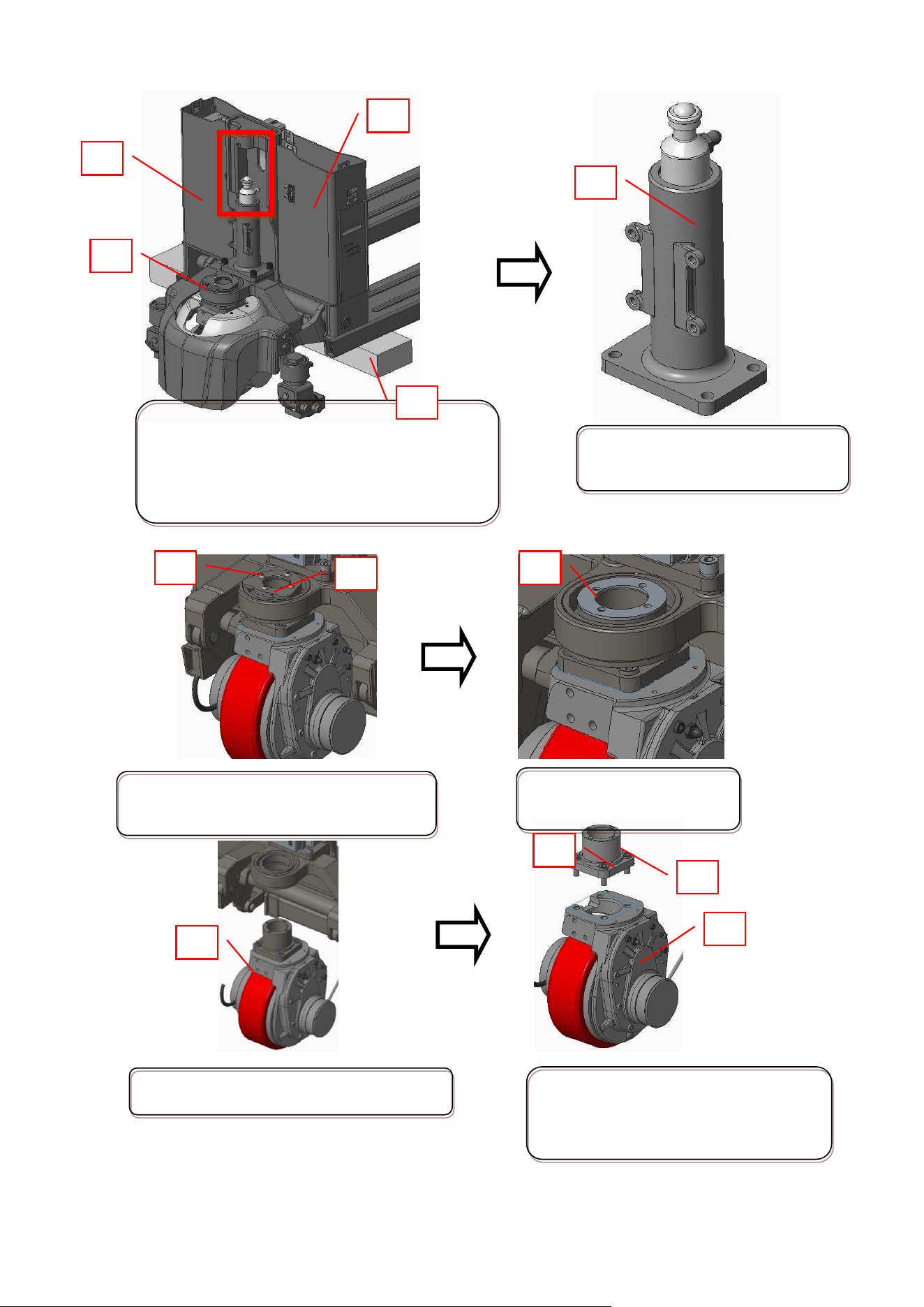
3. Hydraulic system
3.1 Hydraulic schematic diagram
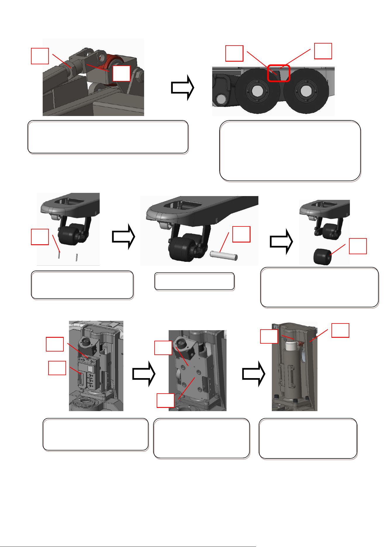
3.2 Cylinder seals replacement
Cylinder
Lowering solenoid valve
One-way
valve
Pump
Oil filter
Throttle valve
Relief valve
Oil tank
2
Lift the truck 1 a little to
disassemble the screw 2 and
oil pipe 3.
1
Separate the truck frame and
the piston rod 4 by lifting the
truck frame again, then take
out the piston 4, and again
piston rod 3 directly.
4
5
7
6
Replace the dust ring 6, seal
ring 5 and the guide tape 7
3
1
11
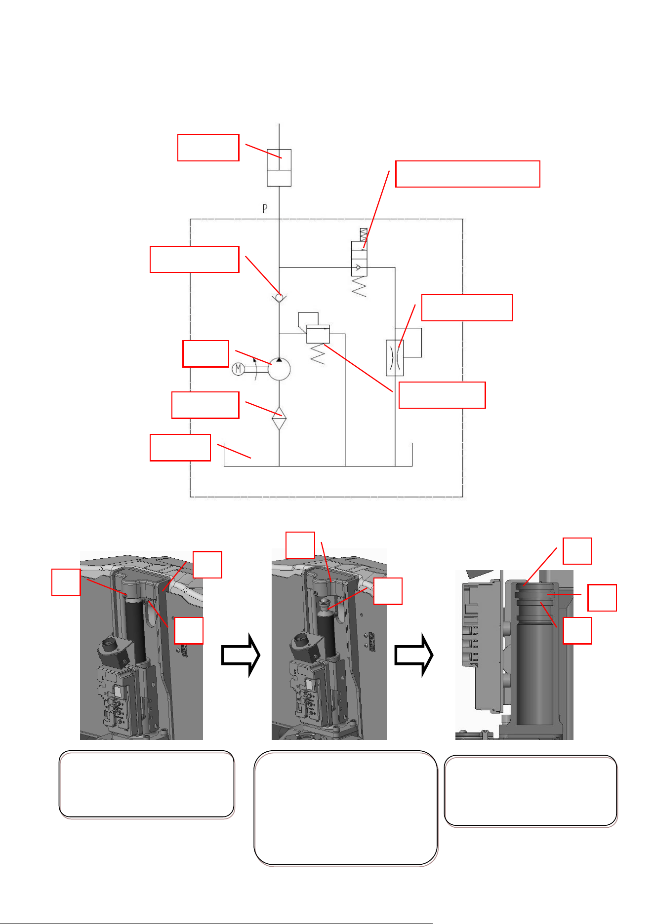
3.3 System pressure adjustment
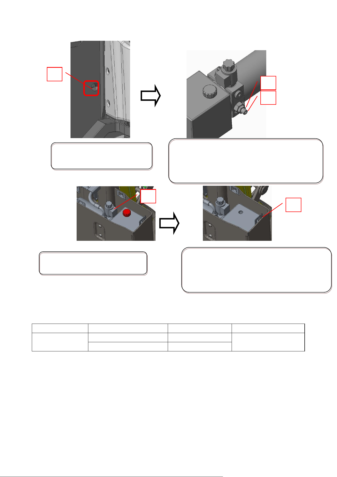
3.4 Add the hydraulic oil
3.5 Lubricating oil specification and required amount
Oil filler
Specification
Amount
Remark
Hydraulic power
unit oil tank
L-HV32
450ml
L-HV15 (low temp.)
450ml
1
Locate the pressure adjusting
valve 1.
Loosen nut 2 and adjusting screw 3 to add the system
pressure clockwise. The system pressure shall not be
over than 115% of the rated capacity, and tighten the
nut 2 after adjustment.
2
1
Find the oi filler and remove the oil
tank cover 1.
2
Fill the need oil into the tank. Required amount is
450ml. Tighten the screw at the filler after adding oil.
Resume to the normal operation after 3 times of
lifting without load.
3
12
4. Electric system
4.1 Electric system diagram
No.
Drawing No.
Description
No.
Drawing No.
Description
1
740.01.0013.01
Tiller head
7
CBD15WE.01.03-02
Buzzer
2
CBD12W-Li.01.02-03
P+ line
8
CBD18KD-Ⅰ.01-03
Proximity
sensor
3
761.02.2100.01
Contactor
9
CBD15W-ⅡLi.01-01
Controller
4
226.02.0800.01
Hoop
831.03.0075.01
Power line
5
718.24.0020.04
Lithium battery
726.04.2406.03
Charger
6
730.01.0080.01
E-stop switch
13
4.2 Electrical schematic diagram
1.5T
1.5T Euro type (new)
14
2T Euro type (new)
4.3 Electrical components
4.3.1 Controller
4.3.1.1 Controller specification
1.5T brush controller
Item
Parameter
Model
D2E-2101
20S output current (Arms)
100A
2Min output current (Arms)
70A
60Min output current (Arms)
30A
Matching motor
DC brush motor
Voltage
24VDC
Temperature
-13°F~+131°F
2T brushless controller
S/N
Item
Parameter
1
Rated voltage
48V
2
2min working current
50A
3
1 hour working current
35A
4
10S working current
70A
5
Working temperature
-13~122°F
6
Storage temperature
-40~185°F
7
Controller derating range
Derating at 185°F~203°F, Stop output at
203°F; derating at -40~-77°F, Stop
output at-40°F.
15
8
Communication type
CAN communication
9
Working humidity
≤95% RH
10
Protection level
IP65(connnector IP54)
11
Tightening torque at terminal end
U、V、W、B+、B-
1.7Nm±0.1Nm
12
Weight
1.6lbs
13
Design life
≥5000h
14
EMC standard
EN12895:2015
15
Safety standard
EN1175、EN13849-1
16
Vibration standard
EN60068-2-6、EN60068-2-27
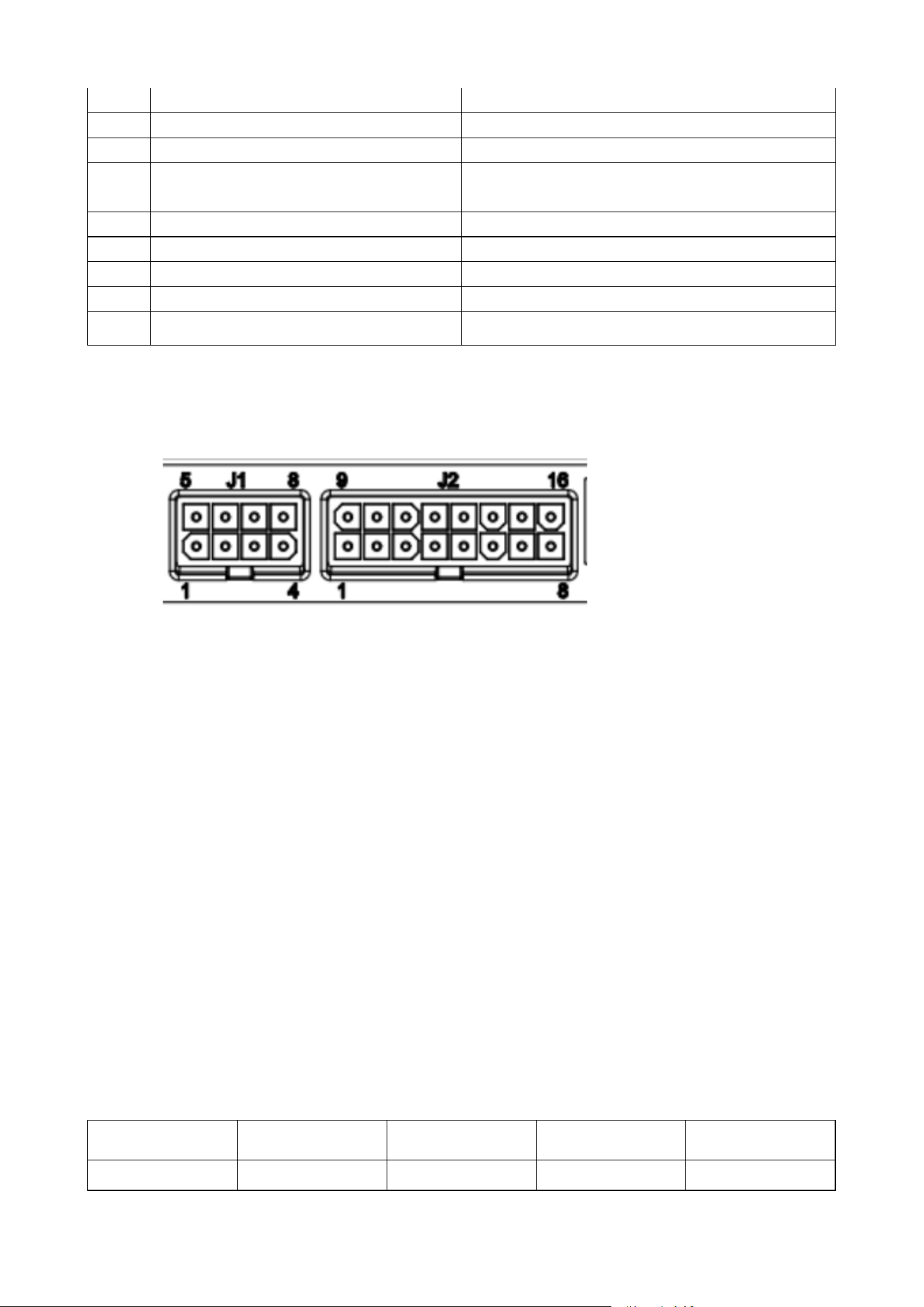
4.3.1.2 Pin identification
4.3.1.3 1.5T controller
J1 J2
J1-1 CANL J2-1 Emergency reverse signal input
J1-2 CANH J2-4 Lifting limit signal input
J1-6 GND J2-8 +24V
J2-10 Interlock signal input
J2-12
J2-13
J2-13
J1-7 CANL
J1-9
J1-11 Lowering signal input
J1-13 CANH
J1-14
2T controller
The power terminal of this driver uses M5 studs, and the signal terminal uses Molex Minifit series
connectors (18PIN, 6PIN, and 4PIN). The specific connector models are shown in the table below:
Position
Brand
Connector seat
mode
Connector mode
Terminal mode
J1
Stark
39281063
39012065
45750
16
J2
Stark
39281043
39012045
45750
J3
Stark
39281183
39012185
45750
J1 connector diagram and pin definition
J1
Pin number
Description
1
5V
2
HALL_A
3
HALL_B
4
HALL_C
5
GND
6
TEMP
Description:
1) Equipped with a motor temperature detection port, which is able to detect the motor temperature.
2) Control algorithm can realize the function of motor Hall sensor disconnection protection.
J2 connector diagram and pin definition
The host computer can set the operating parameters of the controller through this port.
J2
Pin number
Description
1
CANL
2
GND
3
CANH
4
14V
17
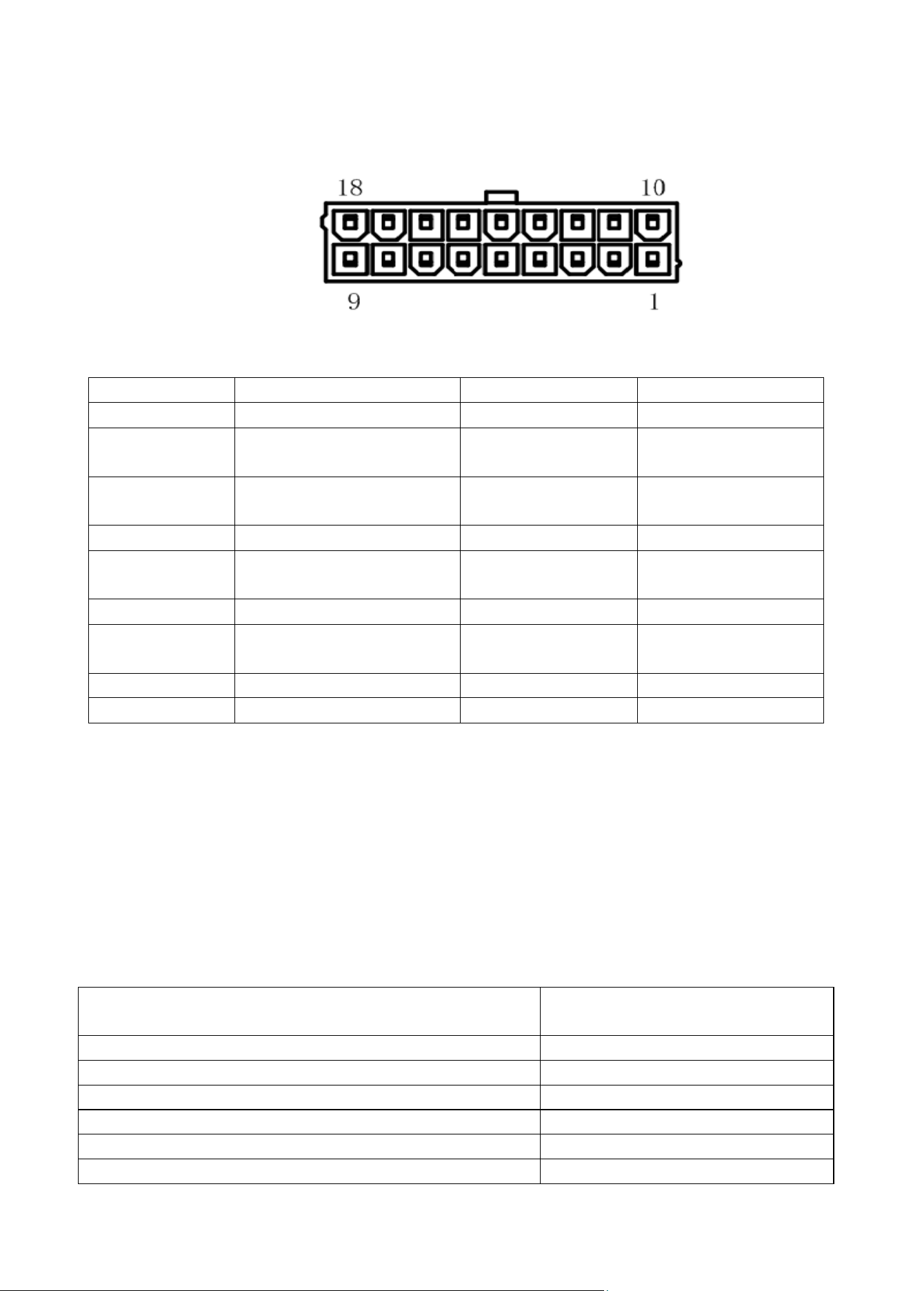
J3 connector diagram and pin definition
Pin number
Description:
Pin number
Description
1
KSI
10
Load circuit
2
Lift pump valve drive
11
Drive of lowering
pump valve
3
Interlock switch
12
Band-type brake
drive
4
Analog/digital port 2
13
Signal ground
5
Battery power
output/fault lamp display
14
Emergency reverse
switch
6
Analog/digital port 1
15
Charging prohibited
7
Throttle sliding end
16
Throttle high level
terminal
8
Backward switch
17
Forward switch
9
Lift switch
18
Mode switch
Description
1. Analog/digital port 1 or analog/digital port 2 can be set as a lowering valve switch through parameters
settings.
2. The fault light display port can be connected to an external LED, and the fault code display can be
achieved by flashing the LED. Slow flashing is ten digits, fast flashing is one digit, and the LED positive
pole is connected to the driver.
4.3.1.4 Controller fault code table
1.5T controller
Fault description
Fault code
Hardware Fault
42
Current Sense Fault
41
Precharge Fault
33
Brake On Fault
32
Battery Disconnect Fault
45
Parameter Fault
43

18
Brake Off Fault
34
Main Relay DNC
21
Wiring Falut
31
Main Driver Fault
23
Main Relay Welded
24
Throttle Fault
12
HPD Fault
35
EMR Sequencing Fault
22
Overvoltage Cutback
15
Undervoltage Cutback
14
Controller Overtemp Cutback
11
Pump SRO Fault
25
Creep Mode Fault
26
SRO Fault
27
Software Fault
36
Motor Temp Hot Cutback
44
Motor Overtemperature
46
Low BDI
51
Controller Overcurrent
52
Controller Severe Overtemp
53
Controller Undertemp Cutback
54
Parameter Change Fault
55
Severe Overvoltage
56
Motor Short
61
Motor Open
62
Gage PDO Timeout
63
PDO Timeout
64
BMS PDO Timeout
65
Driver 1 On Fault
66
Driver 2 On Fault
67
Driver 1 Off Fault
71
Driver 2 Off Fault
72
Severe Undervoltage
29
2T controller
Fault
code
fault type
Possible causes
Trouble shooting
1
Power unit protection
1.The motor is blocked;
2.The internal wiring of the
motor is loose;
3.The working condition is
abnormal
◆Check whether the motor is stuck;
◆Contact the agent or manufacturer;
◆Restart
2
Accelerating over
current
1.Over steep acceleration
curve;
2. Excessive load;
◆Check acceleration and deceleration
time;
◆Remove the overload;

19
3
Deceleration
overcurrent
1. Over steep deceleration
curve;
2. Excessive load;
◆Restart
4
Constant speed
overcurrent
1. Excessive load;
5
Accelerating over
voltage
1. Excessive input voltage;
2. The acceleration curve is
too steep;
◆Regulate the input voltage;
◆Check acceleration and deceleration
time;
◆Restart
6
Deceleration
overvoltage
1. Excessive input voltage;
2. The deceleration curve is
too steep;
7
Constant speed
overvoltage
1. Excessive input voltage;
9
Under voltage fault
1. Instantaneous power
failure of input power
supply;
2. Too low input voltage;
3. The power line is too
thin;
◆ Remove external power supply
problems; Check whether the power
supply is disconnected during
operation and whether the power line
is thick enough;
◆Adjust the input voltage;
◆Restart
12
Motor overload
1. Improper parameter
setting;
2. Excessive load;
◆Adjust parameters;
◆Reduce load;
◆Restart
13
Motor phase loss
1. The internal wiring of
the motor is loose;
2. The motor is damaged;
◆Check the motor for internal damage
caused by external force extrusion;
◆Restart
14
Drive
overtemperature fault
1. Drive temperature too
high
◆Heat dissipation instrument (electric
fan, etc.) can be added for operation
after the temperature drops
◆Restart
23
Parameter setting
failure
Parameter setting error;
◆Set parameters correctly;
◆Restart
24
BUS charging failure
1. Charging circuit failure
◆Contact the agent or manufacturer
25
Memory failure
Motor storage data is
abnormal;
◆Contact the agent or manufacturer;
◆Restart
26
Motor locked-rotor
1. The motor is blocked;
◆Check the load;
◆Restart
27
Reverse rotation of
motor
1. Excessive load reversal;
◆Check the load;
◆Restart
28
Motor out of
synchronism
1. Too fast acceleration
time;
◆Check acceleration and deceleration
time;
◆Restart
29
Velocity loop
saturation
1. Excessive load;
2. The rotation speed is set
too high;
◆Reduce load;
◆Check the set speed;
◆Restart

20
30
IF startup failed
Drive loop fault
◆Contact the agent or manufacturer;
◆Restart
36
Hall sensor fault, not
data between 1~6
1.The Hall sensor inside the
motor is faulty;
Hall detection loop fault
◆Check whether the level jump inside
the motor is normal;
◆Contact the agent or manufacturer;
◆Restart
37
Hall sensor fault,
wrong phase
sequence 1
1.The Hall sensor inside the
motor is faulty;
Hall detection loop fault
◆Check if the internal Hall level jump
of the motor is normal
◆Contact the agent or manufacturer;
◆Restart
38
Hall sensor fault,
wrong phase
sequence 2
1.The Hall sensor inside the
motor is faulty;
Hall detection loop fault
◆Check if the internal Hall level jump
of the motor is normal;
◆Contact the agent or manufacturer;
◆Restart
39
Hall sensor fault,
wrong phase
sequence 3
1.The Hall sensor inside the
motor is faulty;
Hall detection loop fault
◆Check if the internal Hall level jump
of the motor is normal;
◆Contact the agent or manufacturer;
◆Restart
40
Hall sensor fault,
wrong phase
sequence 4
1.The Hall sensor inside the
motor is faulty;
Hall detection loop fault
◆Check if the internal Hall level jump
of the motor is normal;
◆Contact the agent or manufacturer;
◆Restart
41
Hall sensor fault,
wrong phase
sequence 5
1.The Hall sensor inside the
motor is faulty;
Hall detection loop fault
◆Check if the internal Hall level jump
of the motor is normal;
◆Contact the agent or manufacturer;
◆Restart
42
Hall sensor fault,
wrong phase
sequence 6
1.The Hall sensor inside the
motor is faulty;
Hall detection loop fault
◆Check if the internal Hall level jump
of the motor is normal;
◆Contact the agent or manufacturer;
◆Restart
43
Hall sensor failure,
CAP acquiring same
phase sequence for
two consecutive times
1.The Hall sensor inside the
motor is faulty;
Hall detection loop fault
◆Check if the internal Hall level jump
of the motor is normal;
◆Contact the agent or manufacturer;
◆Restart
44
CAP, interval too small
1.The Hall sensor inside the
motor is faulty;
Caused by interference
signal
Hall detection loop fault
◆Check if the internal Hall level jump
of the motor is normal;
◆Contact the agent or manufacturer;
◆Restart
45
CAP interrupt,
non-four-channel
capture signal
abnormal
1.The Hall sensor inside the
motor is faulty;
Hall detection loop fault
◆Check if the internal Hall level jump
of the motor is normal;
◆Contact the agent or manufacturer;
◆Restart
47
Band-type brake load
detection fault
1.Brake circuit is open;
Short circuit of brake circuit
◆Check whether the brake load has
been connected;

21
◆Contact the agent or manufacturer;
◆Restart
48
Pump load detection
failure
1.Open circuit of lifting
pump circuit
Short circuit of lifting pump
circuit
◆Check whether the lifting pump load
has been connected;
◆Contact the agent or manufacturer;
◆Restart
49
Valve load detection
failure
1.Dropping valve circuit is
open
Short circuit of descending
valve circuit
◆ Check whether the lowering valve
load has been connected;
◆Contact the agent or manufacturer;
◆Restart
50
Parameter mismatch
fault
P1.arameter configuration
conflict
◆ Check whether the parameter
configuration is correct;
◆Contact the agent or manufacturer;
◆Restart
51
Pre-charge fault
1.The input voltage is too
low;
KSI voltage pulled down
during use
◆Check whether the input voltage is
reasonable;
◆Check whether KSI voltage is pulled
down during use;
◆Contact the agent or manufacturer;
◆Restart
52
Brake speed fault
1.The rotating speed is
higher than the fault
threshold when the brake is
applied;
◆ Check whether the brake force is
insufficient to cause the slope to slide
down;
◆Contact the agent or manufacturer;
◆Restart
53
Brake output
detection fault
1.Brake circuit is open;
Short circuit of brake circuit
◆Check whether the brake load has
been connected;
◆Contact the agent or manufacturer;
◆Restart
54
Pump output
detection fault
1.Open circuit of lifting
pump circuit;
Short circuit of lifting pump
circuit
◆Check whether the lifting pump load
has been connected;
◆Contact the agent or manufacturer;
◆Restart
55
Dropping valve output
detection fault
1.Dropping valve circuit is
open;
Short circuit of descending
valve circuit
◆ Check whether the lowering valve
load has been connected;
◆Contact the agent or manufacturer;
◆Restart
56
The input voltage of
analog quantity 2 is
judged as incorrect by
the slave computer
1.Open circuit of analog
quantity 2 input circuit slave
circuit
Short circuit of analog
2 input circuit and slave
circuit
◆Check whether the input circuit of
analog quantity 2 is abnormal;
◆Contact the agent or manufacturer;
◆Restart
57
The lifting switch
slave judges that the
1.The input circuit of lifting
switch is in open circuit
◆Check whether the input circuit of
lifting switch is abnormal;

22
IO port is incorrect
The input circuit of lifting
switch is shorted to the
slave circuit
◆Contact the agent or manufacturer;
◆Restart
58
The forward switch
slave judges that the
IO port is incorrect
1.The input circuit of
forward switch is in open
circuit
The input circuit of forward
switch is shorted to the
slave circuit
◆Check whether the input circuit of
forward switch is abnormal;
◆Contact the agent or manufacturer;
◆Restart
59
The mode switch
slave judges that the
IO interface is
incorrect
1.The mode switch input
circuit is open to the slave
circuit
Short circuit of mode switch
input circuit and slave circuit
◆ Check whether the mode switch
input circuit is abnormal;
◆Contact the agent or manufacturer;
◆Restart
60
The reverse switch
slave judges that the
IO interface is
incorrect
1.The input circuit of the
reversing switch is in open
circuit
The input circuit of the
reversing switch is shorted
to the slave circuit
◆Check whether the input circuit of the
reversing switch is abnormal;
◆Contact the agent or manufacturer;
◆Restart
61
Analog 1 input voltage
slave judges that IO
port is incorrect
1.The input circuit of analog
quantity 1 is open to the
slave circuit
Short circuit of analog
quantity 1 input circuit and
slave circuit
◆Check whether the input circuit of
analog quantity 1 is abnormal;
◆Contact the agent or manufacturer;
◆Restart
62
Incorrect IO port
judged by interlocking
switch slave
1.The input circuit of
interlock switch is in open
circuit
The input circuit of interlock
switch is shorted to the
slave circuit
◆ Whether the input circuit of
interlocking switch is abnormal;
◆Contact the agent or manufacturer;
◆Restart
63
The emergency
reverse switch slave
judges that the IO
interface is incorrect
1.The input circuit of
emergency reverse switch is
in open circuit
The input circuit of
emergency reverse switch is
shorted to the slave circuit
◆ Whether the input circuit of
emergency reverse switch is abnormal;
◆Contact the agent or manufacturer;
◆Restart
64
Slave communication
failure
1.The slave MCU is
abnormal;
MCU communication circuit
failure
◆Contact the agent or manufacturer;
◆Restart
65
Third-level fault of
slave
1.The control of main MCU
is out of control, and
emergency treatment from
MCU
◆Contact the agent or manufacturer;
◆Restart

23
66
The slave judges that
the rotating speed is
too high
1.The speed is out of control
and exceeds the maximum
speed by 20%
◆Contact the agent or manufacturer;
◆Restart
67
The internal 5V
voltage is abnormal
1.Internal 5V voltage
fluctuation
Setting error of internal 5V
fault threshold parameter
◆Check whether the parameter setting
is correct
◆Contact the agent or manufacturer;
◆Restart
68
Internal 15V voltage
abnormal
1.Internal 15V voltage
fluctuation
Internal 15V fault threshold
parameter setting error
◆Check whether the parameter setting
is correct
◆Contact the agent or manufacturer;
◆Restart
69
External 5V voltage
abnormal
1. Fluctuation of external 5V
voltage
2. External 5V fault
threshold parameter setting
error
◆Check whether the parameter setting
is correct
◆Contact the agent or manufacturer;
◆Restart
70
Main controller and
battery
communication failure
1.Battery BMS is abnormal;
The communication line
between the main controller
and the battery is
disconnected
◆ Check whether the harness is
complete
◆Contact the agent or manufacturer;
◆Restart
71
Lithium battery
overvoltage fault
1. Overvoltage caused by
charging of lithium battery
2. Voltage rise caused by
electricity generated by the
brake of the controller under
full battery condition
◆Check whether the lithium battery
has been charged and over-voltage
◆Contact the agent or manufacturer;
◆Restart
73
Serious failure of
lithium battery
1. The battery BMS detects
a serious fault.
2. The battery power is
extremely low
◆Check whether the lithium battery
has serious fault
◆Check whether the battery power is
extremely low;
◆Restart
74
Low battery warning
of lithium battery
1.Low battery warning
◆Check whether the battery power is
low;
◆Replace the battery
75
Drive overvoltage
protection failure
1.Instantaneous BUS
voltage is too high
◆ Check whether there is working
condition causing rapid rise of BUSbar
voltage during use;
◆Restart
76
Master and slave MCU
communication failure
1.Master and slave MCU
communication failure
MCU communication circuit
failure
◆Contact the agent or manufacturer;
◆Restart

24
77
Loss of Hall signal
from MCU
1.Open circuit from MCU
Hall circuit
◆Contact the agent or manufacturer;
◆Restart
80
The power-on
self-test interlock
switch is not reset
1.The interlocking switch is
not reset
◆Reset all switches
81
Power-on BIT forward
switch not reset
1.The forward switch is not
reset
◆Reset all switches
82
Power-on self-test
backward switch not
reset
1.The backward switch is
not reset
◆Reset all switches
83
The throttle switch is
not reset during
power-on
self-inspection
1.Throttle switch is not reset
◆Reset all switches
84
Power-on BIT
emergency switch not
reset
1.The emergency reverse
switch is not reset
◆Reset all switches
85
The lifting switch is
not reset during
power-on
self-inspection
1.The lifting switch is not
reset
◆Reset all switches
86
Power-on self-test
lowering valve switch
not reset
1.The lowering valve switch
is not reset
◆Reset all switches
87
Control signal timing
fault
1.Incorrect operation
sequence
◆Reset all switches
88
Vehicle running
direction key failure
1.Forward and backward are
effective at the same time
◆Reset all switches
89
Emergency reverse
warning
1.Triggered after emergency
stop
◆Reset all switches
90
Time sequence fault
1.Incorrect operation
sequence
◆Reset all switches
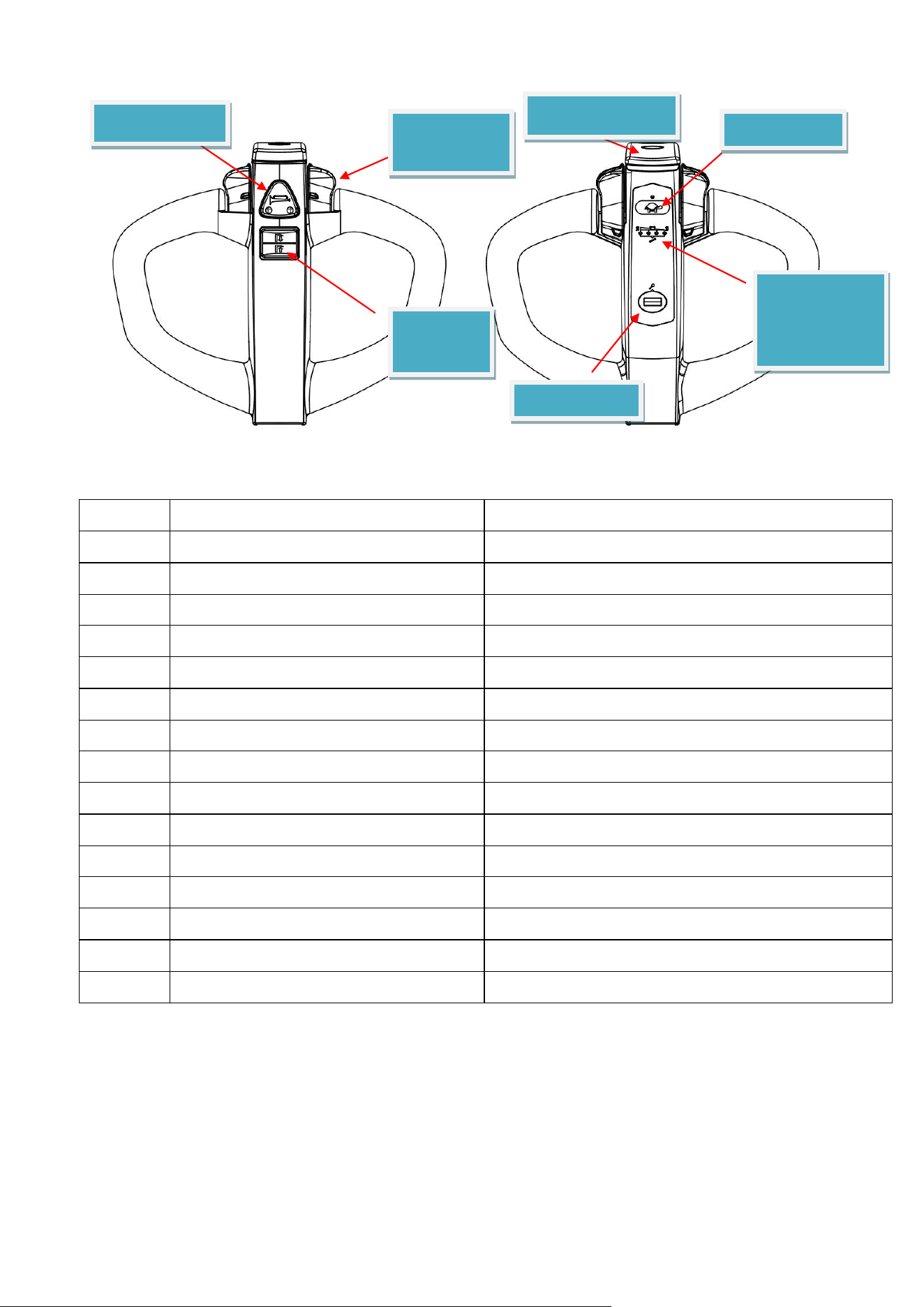
4.3.2 Handle
25
S/N
Function
Description
1
Voltage
24/48V DC
2
Communication type
CAN communication
3
Appearance
Magnetic lock +LED light
4
Accelerator type
Integrated in the tiller head
5
BDI
Receive battery capacity message and display it
6
Fault display
Controller fault and BMS fault
7
Lift signal
CAN OUTPUT
8
Lower signal
CAN OUTPUT
9
Horn signal
Horn signal output
10
Anti-collision signal
High voltage N/O
11
Drive forward signal
CAN OUTPUT
12
Drive backward signal
CAN OUTPUT
13
Accelerating signal
CAN OUTPUT
14
Mode signal
CAN OUTPUT
15
Unlocking signal
CAN OUTPUT
Horn button
Accelerating
rotary knob
Lift/lower
button
E-reverse button
Slow button
Battery
capacity/fault
indicator
Magnetic lock
26
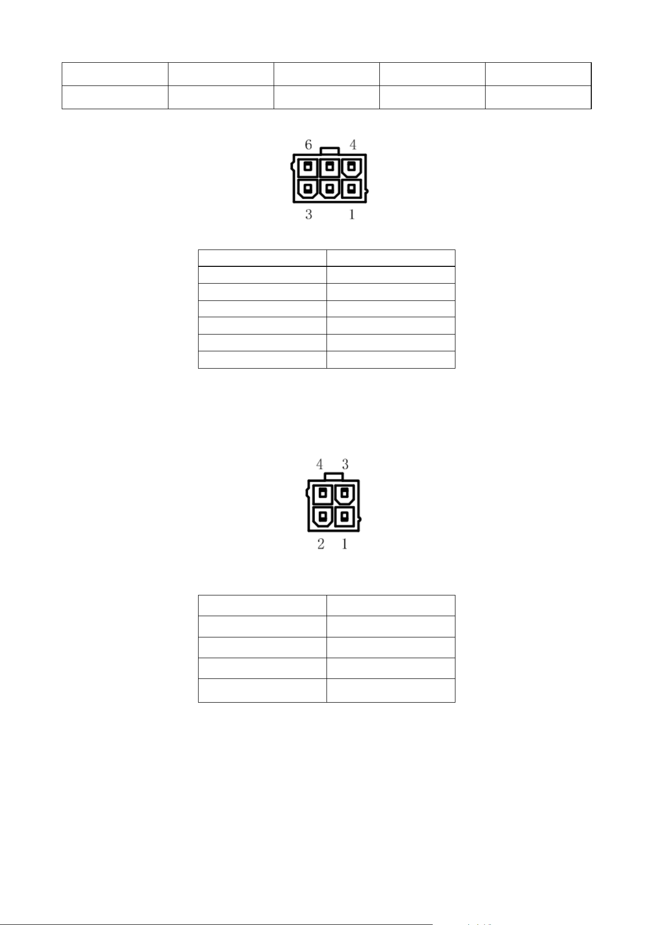
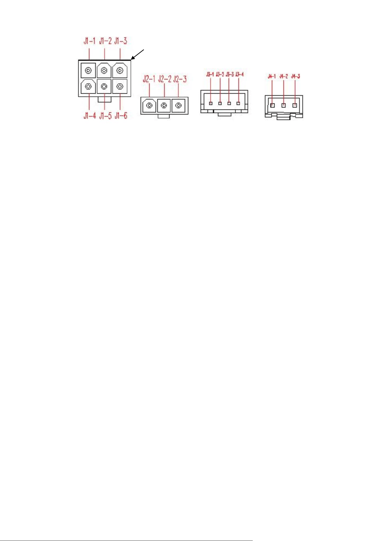
J1-1
B+
J2-1
Lift/lower B+(input)
J1-2
Anti-collision (output)NC
J2-2
Lift signal input
J1-3
GND
J2-3
Lower signal input
J1-4
CAN H(output)
Port identify
Function
J1-5
CAN L(output)
J1-6
Horn(output)NO
Port identify
Function
J3-1
Horn B+(input)
J4-1
Key signal input
J3-2
Anti-collision B+(input)
J4-2
GND
J3-3
Horn(output)
J4-3
5V
J3-4
Anti-collision (input)
Port identify
Function
Port identify
Function
4.3.2.2 Tiller head with a password lock
Designated plug:
5557-6R

—————————————————————— —— 1 —— ——————————————————————
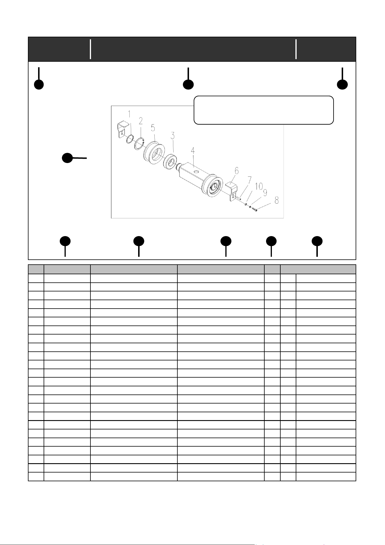
Index No.:0.03
No.
Part No. Description Specification Qty
1
41305000018 Retaining ring 30 2
2
41304000021 Retaining ring 62 2
3
43001000046 Bearing 6206-2RS 2
4
21703000178 Step shaft 1
5
21311000010 Chain roller 2
6
22003000044 Bent plate 2
7
41402000009 Pin 4X20 2
8
41100000041 Screw M6X16 2
9
41300000004 Washer 6 2
10
41301000004 Washer 6 2
Remark
Chain roller assy (130.04.0760.01)
1
2
3
9
4
5
6
7
8
ALL SHOWN IN THIS PAGE IS FOR
—————————————————————— —— 2 —— ——————————————————————

0
0.00 Master assy CBD15W-ⅡLi
0.01 RH balance wheel assy
0.02 LH balance wheel assy
0.03 Lock catch assy
1
1.00 Electric system CBD15W-ⅡLi
1.00A Electric system CBD15W-ⅡLi/Euro type
2
2.00 Hydraulic system CBD15W-ⅡLi
2.01 Cylinder master assy
3
3.00 Steering gear master assy CBD15W-ⅡLi
3.01
Driving wheel master assy
4
4.00 Truck frame assy
4.01 Locking assy
Contents
—————————————————————— —— 3 —— ——————————————————————

Index No.:0.00
No.
Part No. Description Specification Qty
1
30402000225 Steering gear master assy 1
Y See 3.00
2
20521000227 Rear housing 1
3
41004000028 Bolt M10X25 4
4
31303000033 RH balance wheel assy Option 1
Y See 0.01
4
31303000034 LH balance wheel assy Option 1
Y See 0.02
4
21901003056 Rectangular plate For truck without balance wheel 2
5
NULL Electric system 1
Y See 1.00
5
NULL Electric system Euro type 1
Y See 1.00A
6
31601000211 Rocker arm assy 550 1
6
31601000223 Rocker arm assy 685 1
7
41304000005 Retaining ring 20 2
8
21704000030 Pin shaft 1
9
41101000027 Screw M6X8 1
10
30701004378 Truck frame assy 550X1150 1
10
30701004379 Truck frame assy 550X1220 1
10
30701004528 Truck frame assy 550X1150/guide roller 1
10
30701004529 Truck frame assy 550X1220/guide roller 1
10
30701004380 Truck frame assy 685X1150 1
10
30701004381 Truck frame assy 685X1220 1
10
30701004532 Truck frame assy 685X1150/guide roller 1
10
30701004533 Truck frame assy 685X1220/guide roller 1
11
30806000129 Front housing assy 1
12
41102000002 Screw M6X16 4
13
21312000094 Roller Option 2
14 41001000003 Bolt M6X55 Option 2
15 41208000005 Nut M6 Option 2
16 21702000031 Hole pin shaft 2
Remark
Master assy (CBD15W-ⅡLi-00)
—————————————————————— —— 1 —— ——————————————————————
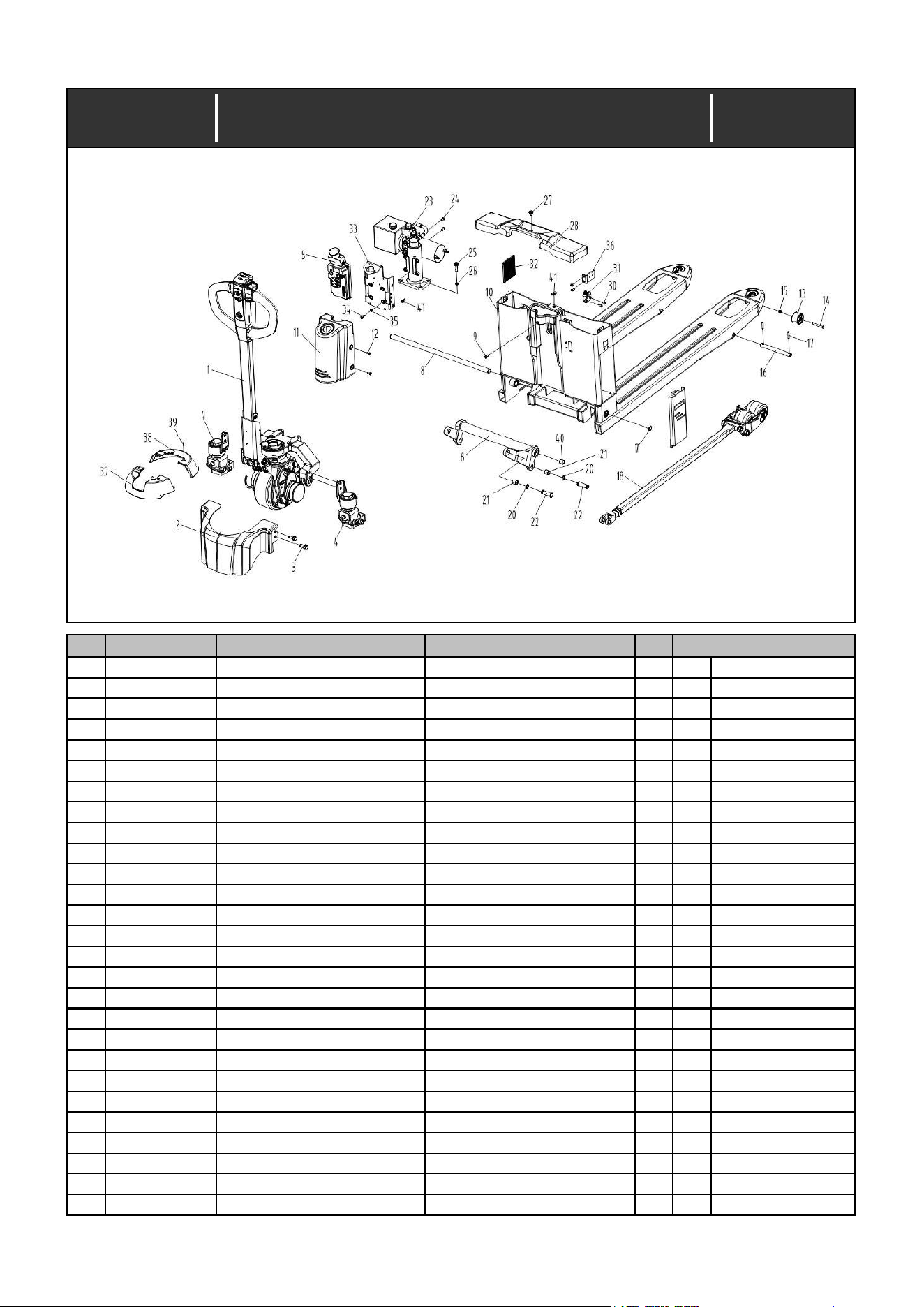
Index No.:0.00
No.
Part No. Description Specification Qty
Remark
Master assy (CBD15W-ⅡLi-00)
2022/11/10
Date:
17 41402000022 Pin 5X32 4
18 31605001910 Connecting rod and roller carriage assy 1150/single roller/Lithium battery 2
Y
See 4.00
18 31605001911 Connecting rod and roller carriage assy 1220/single roller/Lithium battery 2
Y
See 4.00
18 31605001912 Connecting rod and roller carriage assy 1150/double rollers/Lithium battery 2
Y
See 4.00
18 31605001913 Connecting rod and roller carriage assy 1220/double rollers/Lithium battery 2
Y
See 4.00
20 41305000008 Retaining ring 16 4
21 43100000018 Bearing SF-1-16.16 4
22 21703000075 Step shaft 4
23 30201001162 Hydraulic system 1
Y
See 2.00
24 41101000014 Screw M8X12 2
25 41100000099 Screw M10X30 4
26 41300000008 Washer 10 4
27 20101000021 Screw 1
28 20521000229 Housing 1
29 30801000114 Side door assy 1
30 41101000008 Screw M6X12 4
31 31128000014 Lock catch assy 1
Y
See 0.03
32 21412000095 Rubber pad 1
33 31111000189 Support frame assy 1
34 41100000039 Screw M6X14 4
35 41300000004 Washer 6 4
36 22003003723 Bent plate 1
37 20521000230 Front housing 1
38 20521000231 Rear housing 1
39 41102000018 Screw M4X8 4
40 43100000033 Bearing SF -1-20.20 2
41 20102000025 Nut 5
—————————————————————— —— 2 —— ——————————————————————

Index No.:0.01
No.
Part No. Description Specification Qty
1
21304000008 RH balance wheel seat 1
2
21206000147 Fixing seat 1
3
41300000004 Washer 6 2
4
41101000008 Screw M6X12 2
Blackening
5
21809000008 Washer 1
6
43005000006 Bearing 6105-2RS 1
7
41200000008 Nut M8 1
8
41002000012 Bolt M8X20 1
9
21216000046 Bearing seat 1
10
43010000006 Bearing 51105 1
11
31304000017 Blance wheel carriage assy 1
12
41002000026 Bolt M10X70 1
13
41208000008 Nut M10 1
14
21605000038 Compression spring 1
15
41208000009 Nut M14 2
16
43101000021 Bearing SF-1F-150.120 2
17
20104000051 Bolt 1
18
20104000037 Bolt 1
19
41402000015 Pin 4X8 1
20
31308000033 Wheel carriage assy 1
21
21809000192 Washer 1
22
43001000011 Bearing 6202-ZZ 2
23
21312000121 Roller 1
24
30810000034 Protective plate assy 1
Remark
Date:
RH balance wheel assy (010.02.1060.03)
2022/11/10
—————————————————————— —— 3 —— ——————————————————————
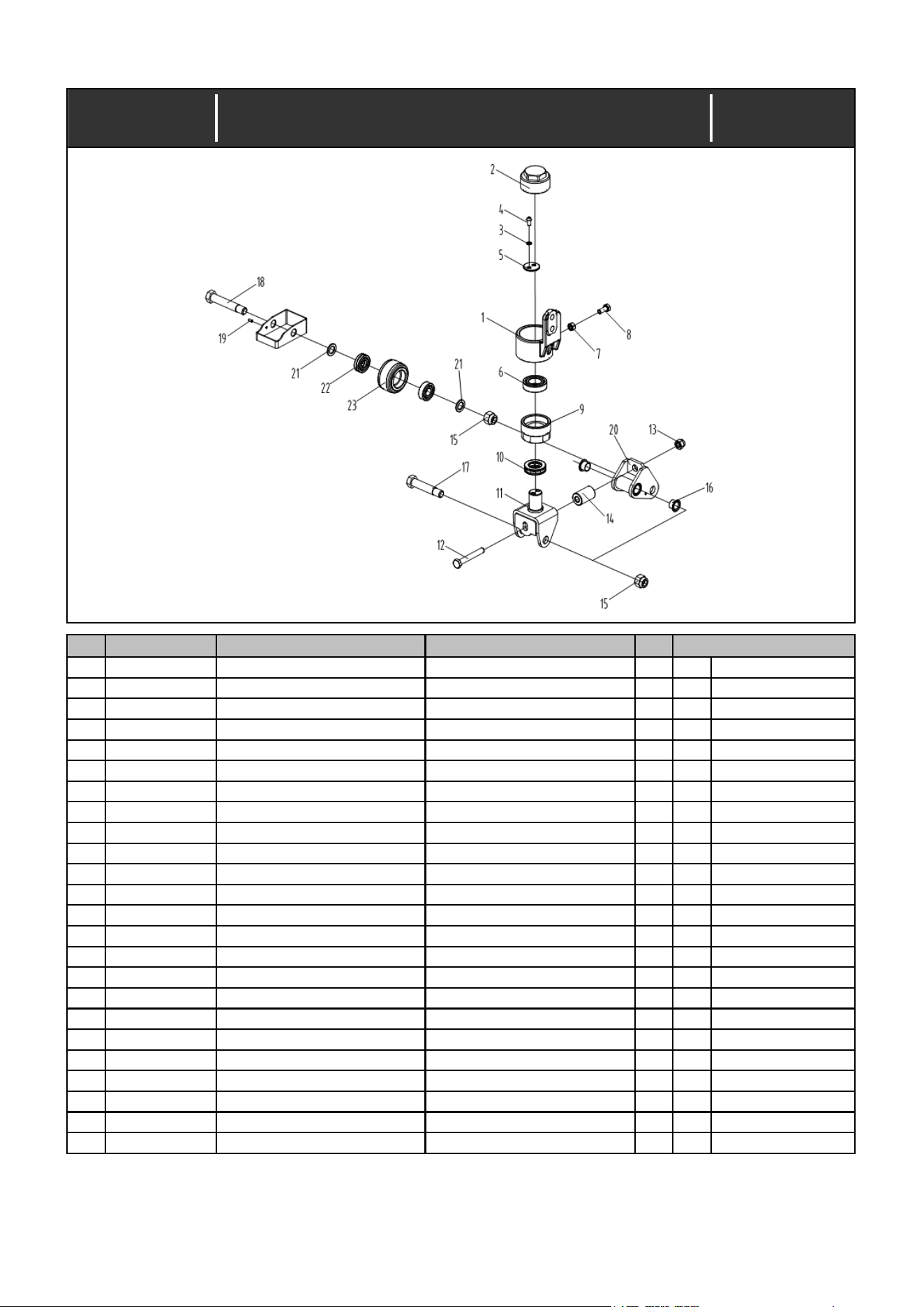
Index No.:0.02
No.
Part No. Description Specification Qty
1
21304000009 LH balance wheel seat 1
2
21206000147 Fixing seat 1
3
41300000004 Washer 6 2
4
41101000008 Screw M6X12 2
Blackening
5
21809000008 Washer 1
6
43005000006 Bearing 6105-2RS 1
7
41200000008 Nut M8 1
8
41002000012 Bolt M8X20 1
9
21216000046 Bearing seat 1
10
43010000006 Bearing 51105 1
11
31304000017 Blance wheel carriage assy 1
12
41002000026 Bolt M10X70 1
13
41208000008 Nut M10 1
14
21605000038 Compression spring 1
15
41208000009 Nut M14 2
16
43101000021 Bearing SF-1F-150.120 2
17
20104000051 Bolt 1
18
20104000037 Bolt 1
19
41402000015 Pin 4X8 1
20
31308000033 Wheel carriage assy 1
21
21809000192 Washer 1
22
43001000011 Bearing 6202-ZZ 2
23
21312000121 Roller 1
24
30810000034 Protective plate assy 1
Remark
Date:
LH balance wheel assy (010.02.1060.04)
2022/11/10
—————————————————————— —— 4 —— ——————————————————————
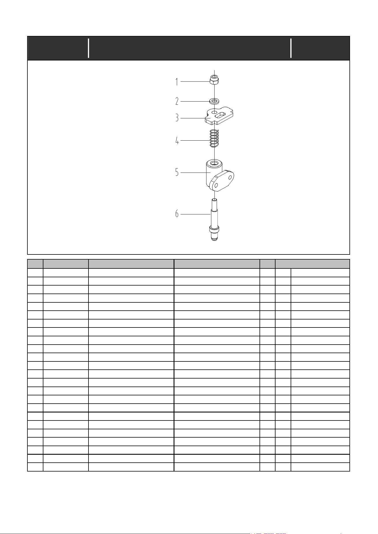
Index No.:0.03
31128000014
No.
Part No. Description Specification Qty
1
41208000005 Nut M6 1
2
41301000004 Washer 6 1
3
21920002149 Irregular plate 1
4
21605000115 Compression spring 1
5
31115000106 Support seat assy 1
6
21703000682 Step shaft 1
Remark
Date:
Lock catch assy (CBD15W-ⅡLi.19-00)
2022/11/10
—————————————————————— —— 5 —— ——————————————————————
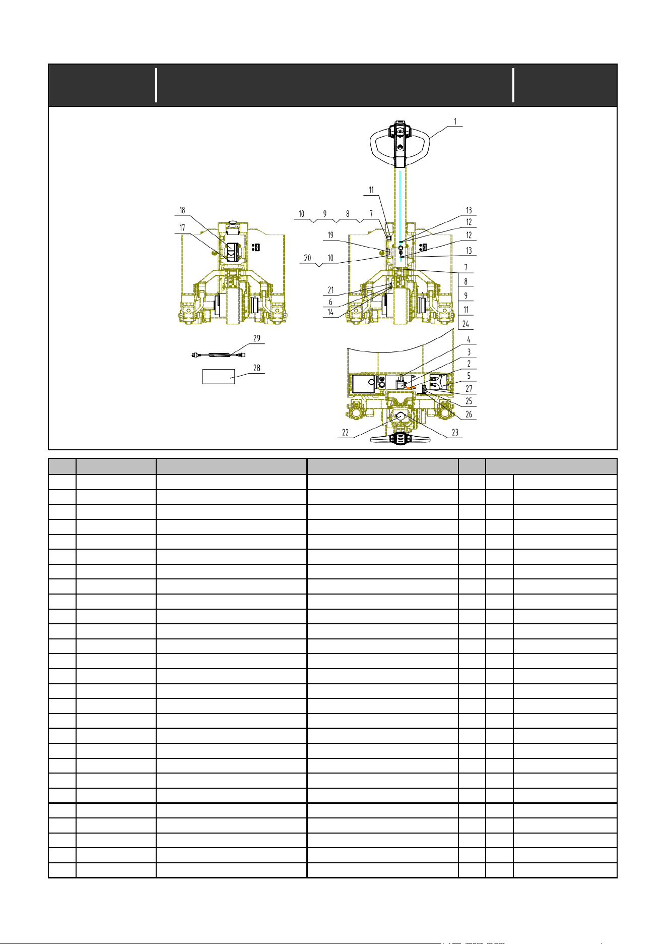
Index No.:1.00
No.
Part No. Description Specification Qty
1
30910000049 Tiller head 1
2
35404000058 Power line 1
3
35902000034 Contactor 1
4
21009000044 Hoop 1
5
35304000234 Lithium battery 1
20AH
5
35304000235 Lithium battery 1
30AH
5
35304000236 Lithium battery 1
50AH
6
41134000005 Screw M4X10 2
7
41100000003 Screw M3X20 4
8
41300000001 Washer 3 4
9
41301000001 Washer 3 4
10
41208000001 Nut M3 4
11
35806000019 Proximity sensor 2
12
41108000011 Screw M4X8 2
13
21006000009 Fixing buckle 2
14
20431000006 Terminal box 1
15
35401000752 Control wiring harness 1
Mounted in the harness
15
20416000026 Fuse 1
16
35401000753 Control wiring harness 1
17
41134000012 Screw M4X25 2
Blackening
18
35105000048 Controller 1
19
35703000008 Alarm 1
20
41108000004 Screw M3X12 2
21
41108000013 Screw M4X10 2
22 35601000008 Emer.stop switch 1
23 41109000015 Screw M5X12 2
24 21901003405 Rectangular plate 2
Remark
Date:
Electric system (CBD15W-ⅡLi.01-00)
2022/11/10
—————————————————————— —— 6 —— ——————————————————————
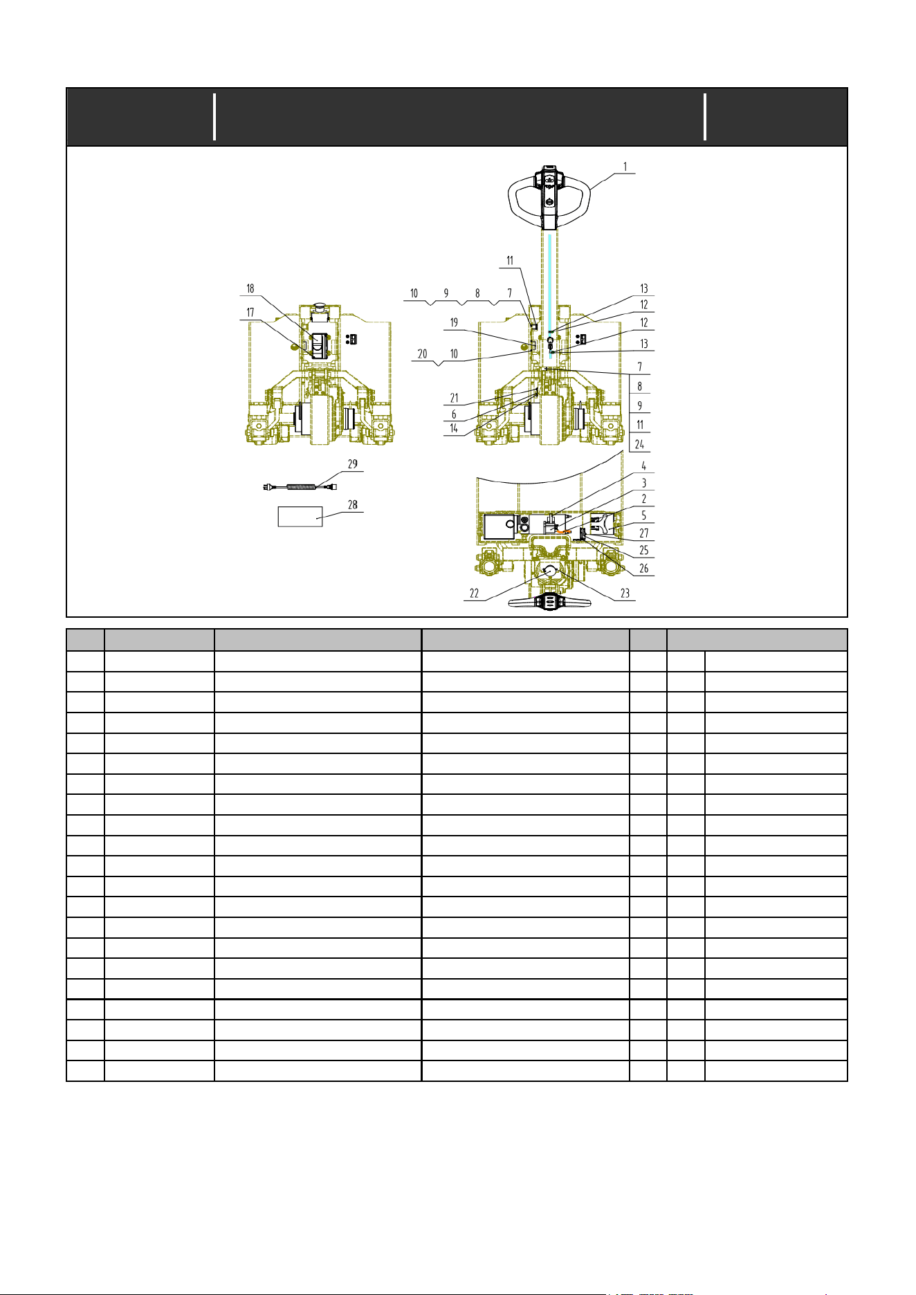
Index No.:1.00
No.
Part No. Description Specification Qty
Remark
Date:
Electric system (CBD15W-ⅡLi.01-00)
2022/11/10
25 35612000044 Micro switch 1
26 21912000035 Spacer 2
27 41134000002 Screw M3X25 2
Blackening
28 35206000323 Charger 1 European type
29 20413000022 Power line 1 Chinese type
29 20413000023 Power line 1 Asian type
29 20413000024 Power line 1 American type
29 20413000025 Power line 1 British type
29 20413000026 Power line 1 Swiss type
29 20413000027 Power line 1 Australian type
29 20413000028 Power line 1 Japanese type
29 20413000029 Power line 1 Brazilian
29 20413000030 Power line 1
—————————————————————— —— 7 —— ——————————————————————
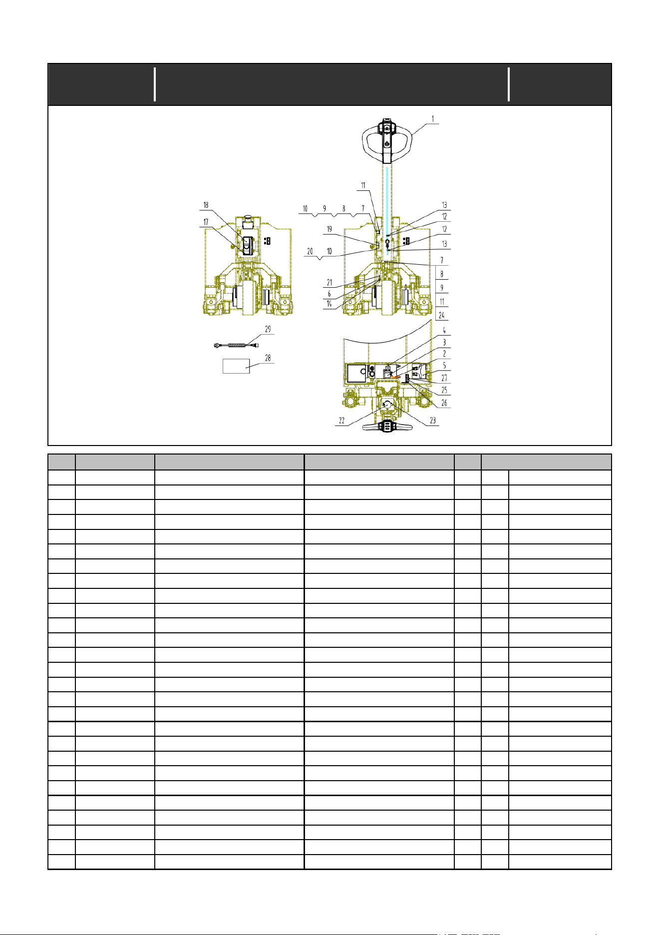
Index No.:1.00A
No.
Part No. Description Specification Qty
1
30910000060 Tiller head 1
2
35404000058 Power line 1
3
35902000034 Contactor 1
4
21009000044 Hoop 1
5
35304000294 Lithium battery 1
6
41134000005 Screw M4X10 2
7
41100000003 Screw M3X20 4
8
41300000001 Washer 3 4
9
41301000001 Washer 3 4
10
41208000001 Nut M3 4
11
35806000019 Proximity sensor 2
12
41108000011 Screw M4X8 2
13
21006000009 Fixing buckle 2
14
20431000006 Terminal box 1
15
35401000905 Control wiring harness 1
15
20416000026 Fuse 1
Mounted in the harness
16
35401000906 Control wiring harness 1
17
41134000012 Screw M4X25 2
Blackening
18
35105000056 Controller 1
19
35703000008 Alarm 1
20
41108000004 Screw M3X12 2
21
41108000013 Screw M4X10 2
22
35601000008 Emer.stop switch 1
23
41109000015 Screw M5X12 2
24 21901003405 Rectangular plate 2
25 35612000044 Micro switch 1
26 21912000035 Spacer 2
Remark
Electric system (CBD15W-ⅡLi/Y.01-00)
—————————————————————— —— 8 —— ——————————————————————

Index No.:1.00A
No.
Part No. Description Specification Qty
Remark
Date:
Electric system (CBD15W-ⅡLi/Y.01-00)
2022/11/10
27 41134000002 Screw M3X25 2
Blackening
28 35206000376 Charger 1
29 20413000022 Power line 1 European type
29 20413000023 Power line 1 Chinese type
29 20413000024 Power line 1 Asian type
29 20413000025 Power line 1 American type
29 20413000026 Power line 1 British type
29 20413000027 Power line 1 Swiss type
29 20413000028 Power line 1 Australian type
29 20413000029 Power line 1 Japanese type
29 20413000030 Power line 1 Brazilian
—————————————————————— —— 9 —— ——————————————————————
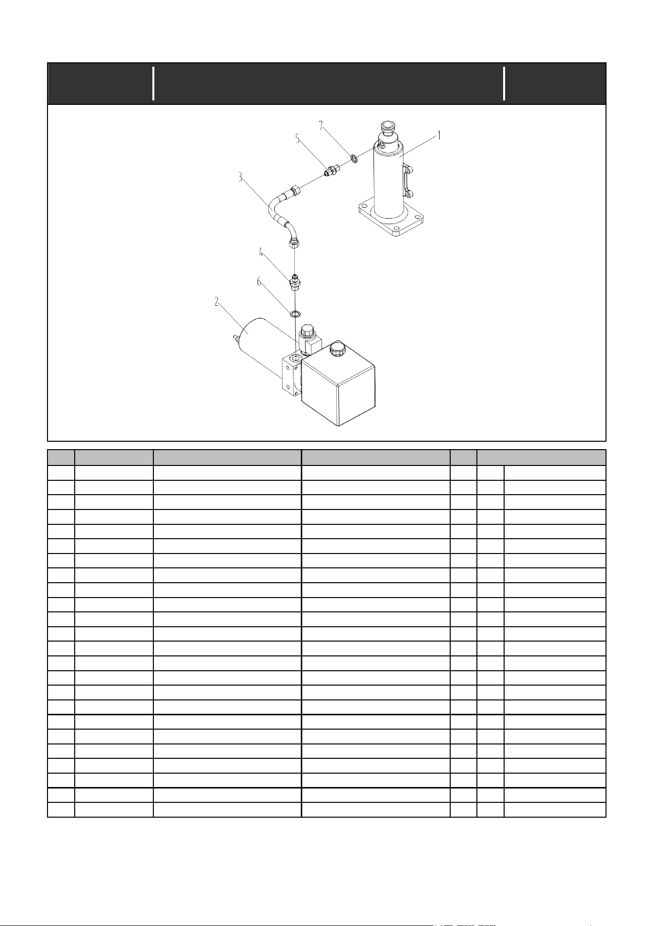
Index No.:2.00
No.
Part No. Description Specification Qty
1
31003000855 Cylinder master assy 1
Y See 2.01
2
30217000095 Hydraulic station assy 1
3
31016000790 High pressure hose 1
4
20313000290 Joint 1
5
20313000003 Joint 1
6
44007000008 Bonded washer 14 1
7
44007000026 Bonded washer 12 1
Remark
Date:
Hydraulic system(CBD15W-ⅡLi.02-00)
2022/11/10
—————————————————————— —— 10 —— ——————————————————————
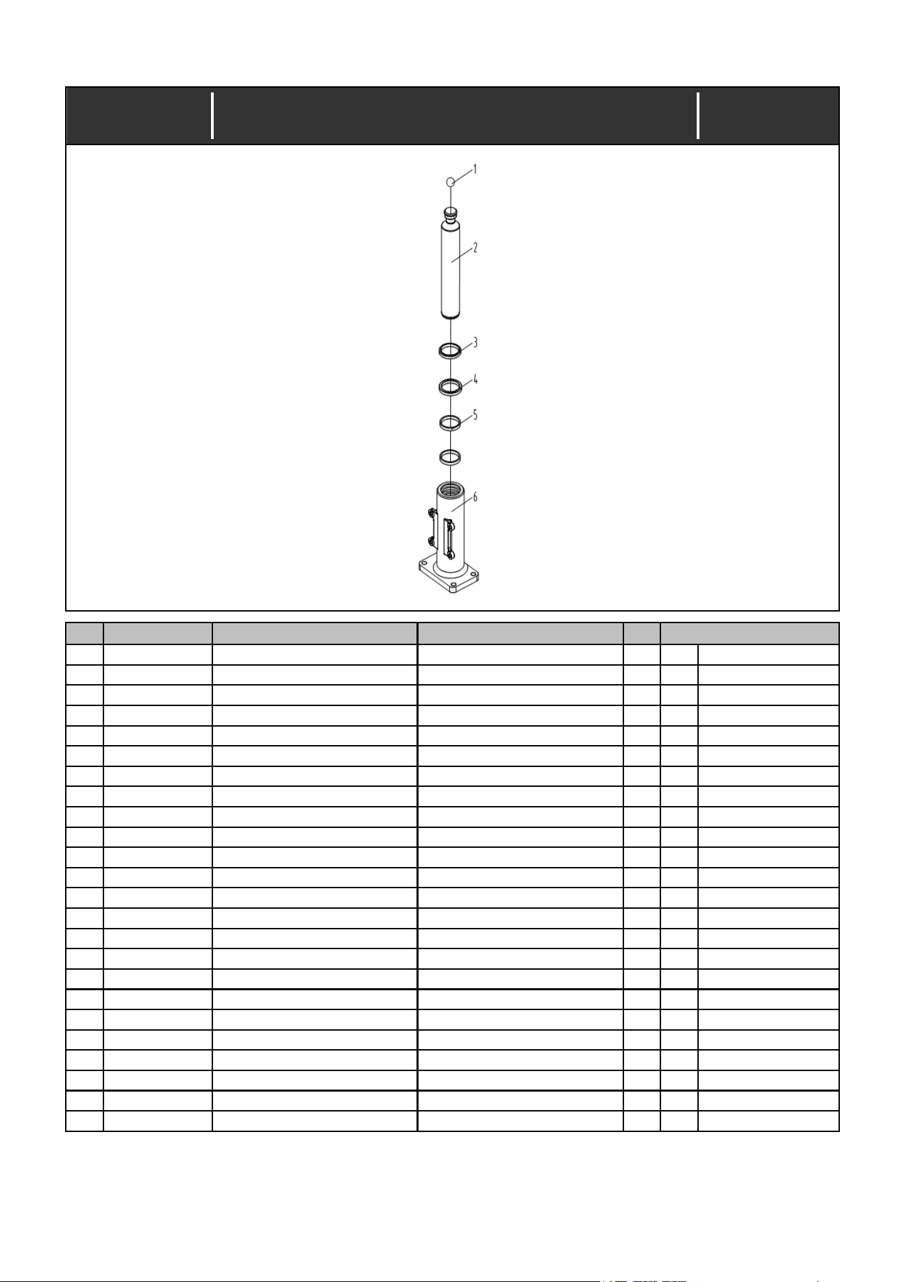
Index No.:2.01
31003000855
No.
Part No. Description Specification Qty
1
40002000017 Steel ball 19.05 1
2
20304000430 Piston rod 1
3
44112000017 Dust ring DH40-48-5/6.5 1
4
44100000020 Seal ring UHS40-50-6 1
5
44115000003 Guide tape BST5806-6-2.5 2
6
21205000118 Base seat 1
Remark
Date:
Cylinder master assy (495.01.0400.20)
2022/11/10
—————————————————————— —— 11 —— ——————————————————————
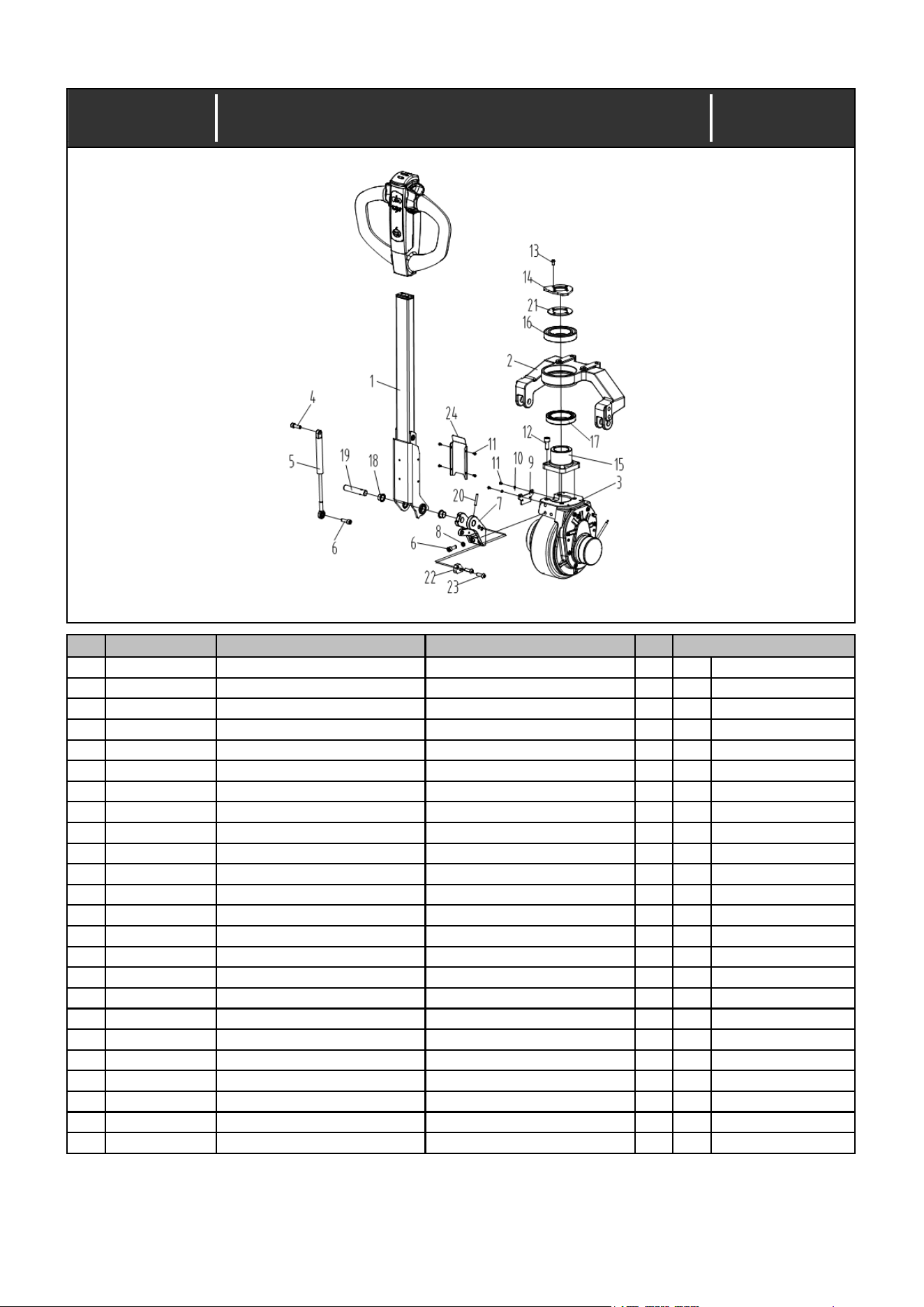
Index No.:3.00
No.
Part No. Description Specification Qty
1
30907000163 Tiller assy 1
2
21213000083 Support seat 1
3
30304000019 Driving wheel master assy 1
Y See 3.01
4
20101000010 Screw 1
5
21607000031 Damping gas spring 1
6
41100000068 Screw M8X25 4
7
21212000008 Tiller seat 1
8
41300000005 Washer 8 3
9
21920002141 Irregular plate 1
10
41300000002 Washer 4 2
11
41108000014 Screw M4X10 6
12
41100000097 Screw M10X25 4
13
41101000009 Screw M6X16 4
14
21809000190 Washer 1
15
21207000009 Pedestal 1
16
43001000084 Bearing 6013-2RS 1
17
43005000005 Bearing 32913 1
18
43101000004 Bearing SF-1F-160.120 2
19
21702000231 Hole pin shaft 1
20
41402000024 Pin 5X35 1
21
21809000191 Washer 1
22
21920002214 Irregular plate 1
23
41101000025 Screw M8X25 2
24
22003003558 Bent plate 1
Remark
Date:
Master assy (CBD15W-ⅡLi-00)
2022/11/10
—————————————————————— —— 12 —— ——————————————————————
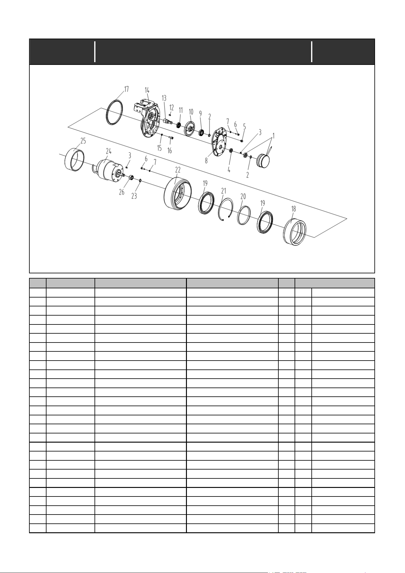
Index No.:3.01
No.
Part No. Description Specification Qty
1
90030000501 Brake 1
2
41305000007 Retaining ring 15 2
3
42001000006 Flat key 5X5X14 2
4
44005000036 Skeleton oil seal 16X28X7(TC) 1
5
44001000003 Oil inlet M8X1 1
6
41100000043 Screw M6X20 16
7
41300000004 Washer 6 16
8
90010000147 Case cover 1
9
43001000035 Bearing 61905-ZZ 1
10
90010000146 Tooth plate 1
11
43001000124 Bearing 16003-2Z 1
12
42001000009 Flat key 5X5X20 1
13
90010000145 Straight tooth 1
14
90010001058 Case 1
15
41300000005 Washer 8 5
16
41100000071 Screw M8×35 5
17
90010000143 Oil seal OTC155X173.2X8.5 1
18
90010000142 Straight ring 1
19
43001000119 Bearing 61824-2RS 2
20
90010000141 Washer 1
21
41304000038 Retaining ring 150 1
22
90010001059 Wheel 1
23
41305000008 Retaining ring 16 1
24
90030000502 Brush motor 1
25 90010001060 Protective ring 1
26 90010000140 Helical tooth 1
Remark
Date:
Driving wheel with horizontal mounted motor master
assy (082.01.0210.04)
2022/11/10
—————————————————————— —— 13 —— ——————————————————————
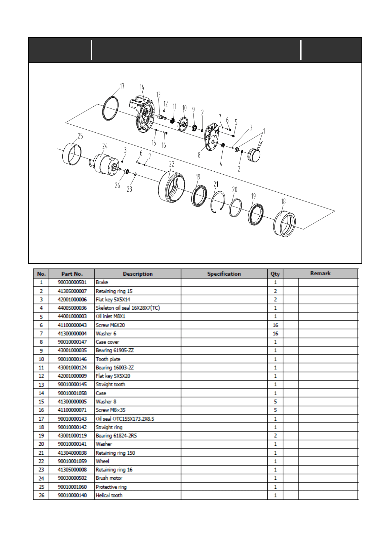
Index No.:3.01
Driving wheel with horizontal mounted motor master
assy (082.01.0210.04)
—————————————————————— —— 14 —— ——————————————————————
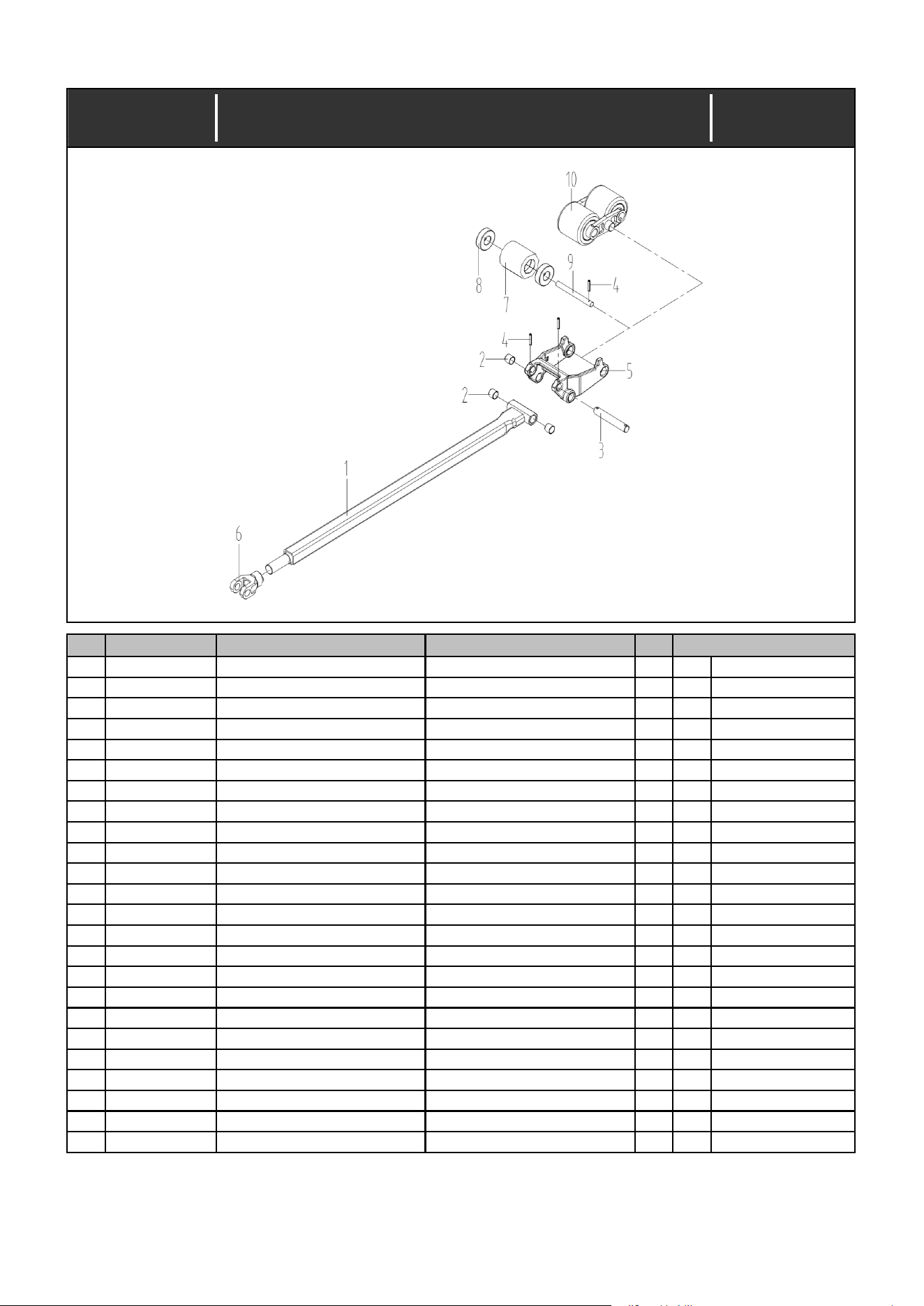
Index No.:4.00
No.
Part No. Description Specification Qty
1
31603000507 Connecting rod assy 1150 1
1
31603000508 Connecting rod assy 1220 1
2
43100000019 Bearing SF-1-16.20 4
3
21702000023 Hole pin shaft 1
4
41402000022 Pin 5X32 For single roller 2
5
21306000023 Wheel carriage 1
6
21106000021 Joint 1
7
21312000148 RollerΦ80X93 1
8
43001000025 Bearing 6204-2RS For single roller 2
9
21702000059 Hole pin shaft For single roller 1
10
31302000075 Double rollers assy 1
Y See 4.01
Remark
Date:
Connecting rod and roller carriage assy
(CBD15W-ⅡLi.16-00)
2022/11/10
—————————————————————— —— 15 —— ——————————————————————
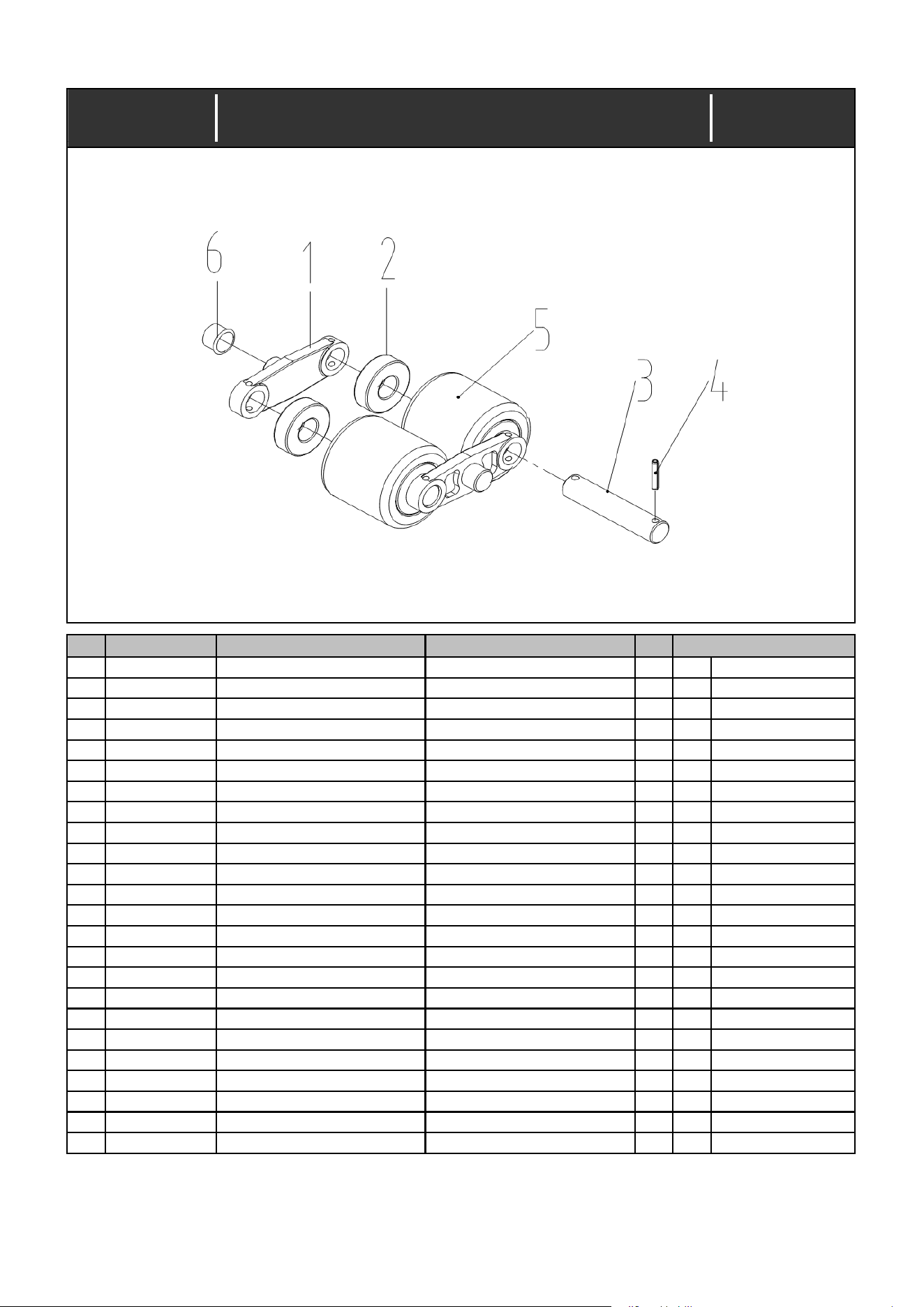
Index No.:4.01
31302000075
No.
Part No. Description Specification Qty
1
21221000016 Support plate 2
2
43001000025 Bearing 6204-2RS 4
3
21702000049 Hole pin shaft 2
4
41402000022 Pin 5X32 4
5
21312000152 RollerΦ80X70 2
Red
6
43101000006 Bearing SF-1F-180.120 2
Remark
Date:
Double rollers assy (010.01.2080.08)
2022/11/10
—————————————————————— —— 16 —— ——————————————————————