LPT33/LPT44 Series
Electric Pallet Truck
Maintenance & Use Instruction
Warning! Please read this manual carefully before
using this device.
Warning! Do not enable this function when all
components are not fully installed with this device.

CONTENT
1.The General Introduction ...................................................................................... 1
2.Proper usage ............................................................................................................ 2
3.Introduction of the product...................................................................................... 3
3.1 Model overview ............................................................................................... 3
3.2 Model parameters ......................................................................................... 3
4.Operating principle ................................................................................................ 6
5.Operating principle ................................................................................................ 7
5.1 Running system ............................................................................................... 7
5.2 Steering system ............................................................................................... 7
5.3 Brake structure and brake schematic diagram. ............................................ 7
5.4 Operating System ............................................................................................ 9
5.5 Electric System ................................................................................................ 9
5.6 Hydraulic principle ......................................................................................... 9
6.Electrical schematic diagram ............................................................................. 10
7.Hydraulic Scheme ................................................................................................. 16
8.Operating Instruction .......................................................................................... 18
8.1 Operation ....................................................................................................... 18
8.2 Emergency reverse function ........................................................................ 20
8.3 The use of the horn and the reversing horn ............................................... 20
8.4 Battery capacity display ............................................................................... 20
8.5 Handling stacking operation ........................................................................ 20
9.Safety operation and matters needing attention ........................................... 22
9.1 Repair and Maintenance ............................................................................... 22
9.2 Routine Maintenance .................................................................................... 23
9.3 Professional Maintenance Manual ............................................................... 23
9.4 Battery maintenance, charging and maintenance. ..................................... 25
10.Safety Caution...................................................................................................... 29
10.1 General rule ................................................................................................. 29
10.2 Storage and transportation ........................................................................ 26
10.3 Check before using ...................................................................................... 30
10.4 Safety operation regulation ........................................................................ 30
11.Service Manual .................................................................................................... 34
11.1 Troubleshooting .......................................................................................... 34
11.2 Preparation before repair .......................................................................... 35
11.3 Check the amount of hydraulic oil ............................................................. 35
11.4 Complete repair, the preparation before using ........................................ 35
1
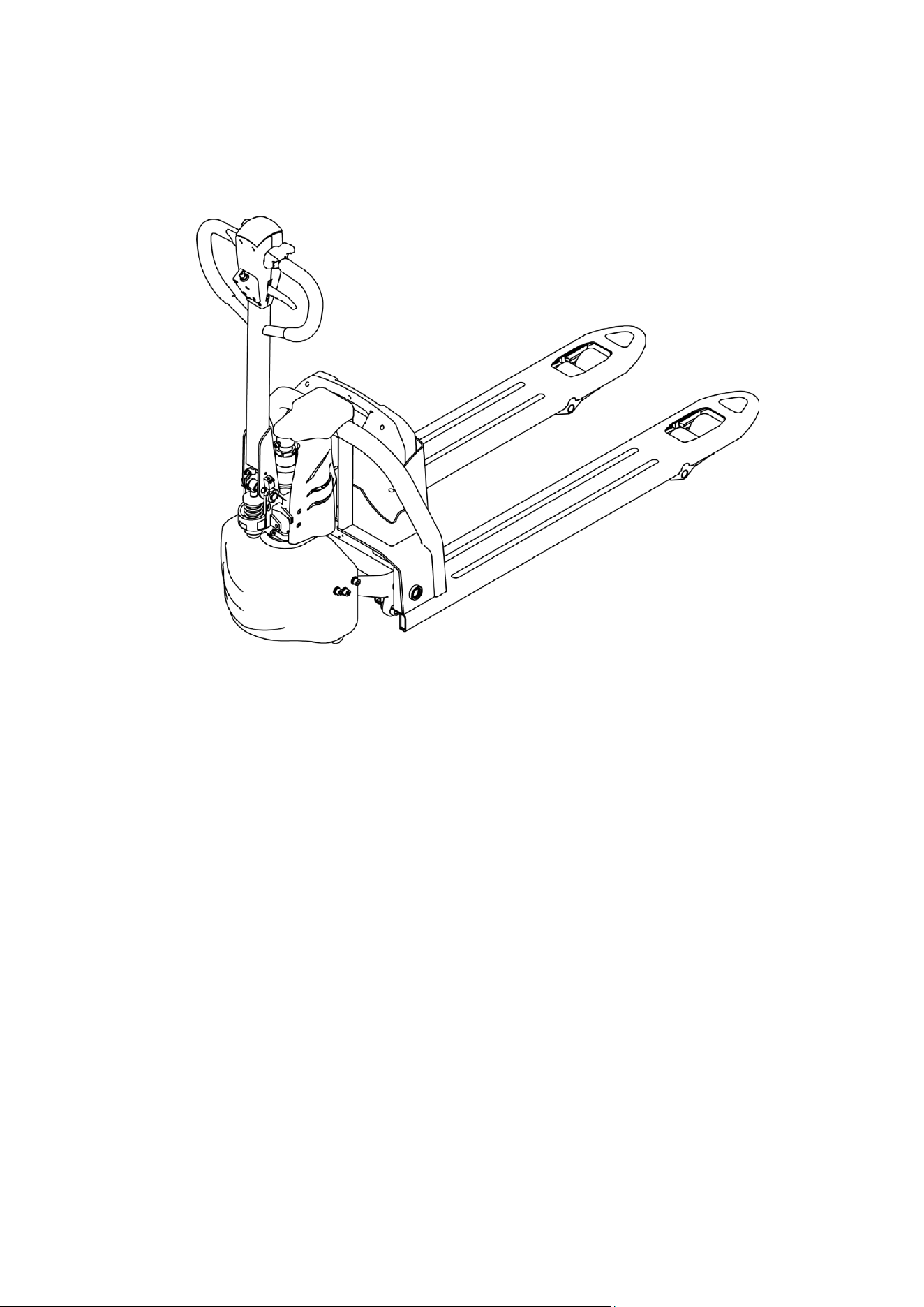
1.The General Introduction
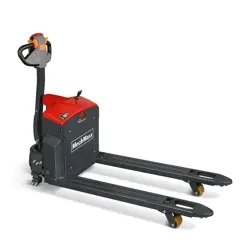
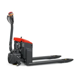
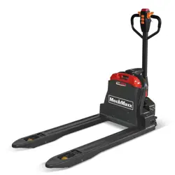
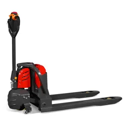
LPT33/LPT44 is a Walkie type electric pallet truck. It adopts the advanced structure such as
ring rod lifting system and DC controller, at same time it is equipped with high quality motor,
lithium battery and pump station motor. It has the characteristics of superior performance,
convenient operation, flexible steering, reliable braking, good dynamic performance, less
noise, less pollution and beautiful appearance.
This series truck is suitable for working on the smooth ground in warehouse, if not, please
don’t use it.
The service environment:
a. Altitude does not exceed 1200 meters
b. temperature not over +40℃,not under +5℃;
c. when environment temperature at +40℃,the relative humidity can’t over 50%,At
low temperature,allow big relative humidity;
d. ground need hard and flat;
e. It is forbidden to use this car in corrosive environment such as flammable and
explosive or acid base.

2
2.Proper usage
Please using the electric pallet truck accord to this specification.
This is a tramp type electric pallet truck with autonomous control, lifting and lowering
is controlled by the handle button.
Improper use can cause personal injury or machine damage. Operators or operating
companies need to ensure proper using, at the same time ensure that the truck is only
operated by trained and authorized personnel.
The Truck needs to be used on a firm , flat ,intact surface and suitable surface ,The truck
is designed for indoor use at room temperature from+5°C to +40°C
Use under light load without using permanent barriers or pits , It is forbidden to
operate on the slops. During Operation ,The goods must be placed approximately at the
center of the truck’s load center
Lifting or Carrying people is strictly prohibited ,If carried goods .The goods must fall on
the lifting point 。
It is prohibited to use this truck on lifting or loading ramps.
The rated capacity is marked on the capacity label or nameplate. And the operator must
pay attention to the warming signs and safty instructions.
Operating lighting must be at lest 50LUX
Modification
Any modification that may affect the truck rated capacity, stability, or safety operations must
be approved in advance by the Truck’s original manufacturer or Its authorized Manufacturer
or its successor. This includes the effects of changes such as Braking ,steering ,Visibility, and
the addition of removable accessories.
After the manufacturer or its successor approves the modification or change, The capacity
name plate, Label, identification marks, operation and maintenance manual must be changed
accordingly
Truck damage caused by not following Instruction will lose its warranty.
3
3.Introduction of the product
3.1Model overview
This specification is for LPT33/LPT44 series Walike type electric pallet truck(follow as
truck).
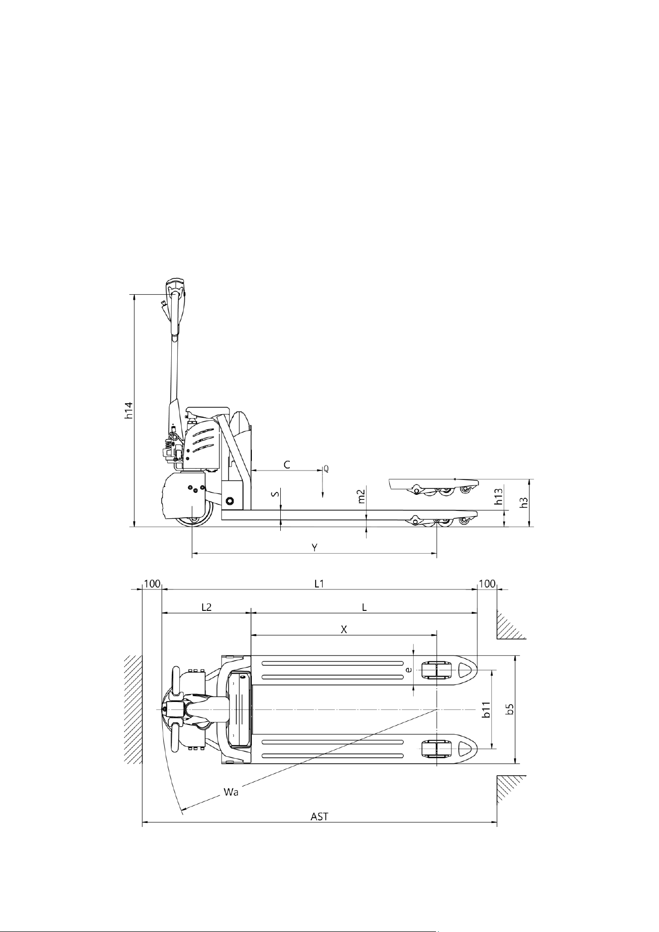
3.2Model parameters

4
Model
LPT33
LPT44
Drive type
Battery
Battery
Operation type
Pedestrian
Pedestrian
Load Capacity
Q (lbs)
3300
4400
Load Centre
c (in)
23.6
23.6
Distance between fork backrest and front wheel
x (in)
37.2
37.2
Wheel Base
y (in)
48.9
48.9
Service Weight (with battery)
Lbs
313
322
Tire material
PU
PU
Driving wheel size
Φ×w(in)
Φ8.3×2.8
Φ8.3×2.8
Balance wheel size
Φ×w(in)
Φ3.2×2.4
Φ3.2×2.4
Tread
b11 (in)
21.1
21.1
Lifting Height
h3 (in)
7.5
7.5
The height of handle in the operation position
h14 (in)
29.1/45.7
29.1/45.7
Lowered fork height
h13 (in)
2.95
2.95
Overall Length
l1 (in)
65.9
65.9
Body Length
l2 (in)
17.8
17.8
Overall Width
b1/ b2 (in)
27
27
Fork Size
s/e/l (in)
2/5.9/48
2/5.9/48
Fork Width
b5 (in)
27
27
Ground clearance under mast
m2 (in)
1.4
1.4
Aisle width for pallets 1000*1200 crossways
Ast (in)
71
71
Aisle width for pallets 1000*1200 lengthways
Ast (in)
73
73
Turing Radius
Wa (in)
55
55
Driving Speed, laden/unladen
(mph)
2.6/2.8
2.6/2.8
Maximum gradeability, laden/unladen
(%)
5/10
5/10
Brake Type
Electromagnetic
Electromagnetic

5
Drive Motor
(kW)
0.75
0.75
Lift Motor
(kW)
0.8
0.8
Battery, according to DIN 43531/35/36 A,B,C,no
no
no
Battery voltage/rate capacity
(V/Ah)
24/20
24/30
24/40
48/ 20
48/30
Battery Weight(±5%)
(lbs)
13.2
22.5
29.1
22.5
29.1
Type of drive control
DC
DC
Noise level
(dB(A))
≤70
≤70
Steering type
Mechanical
Mechanical
6
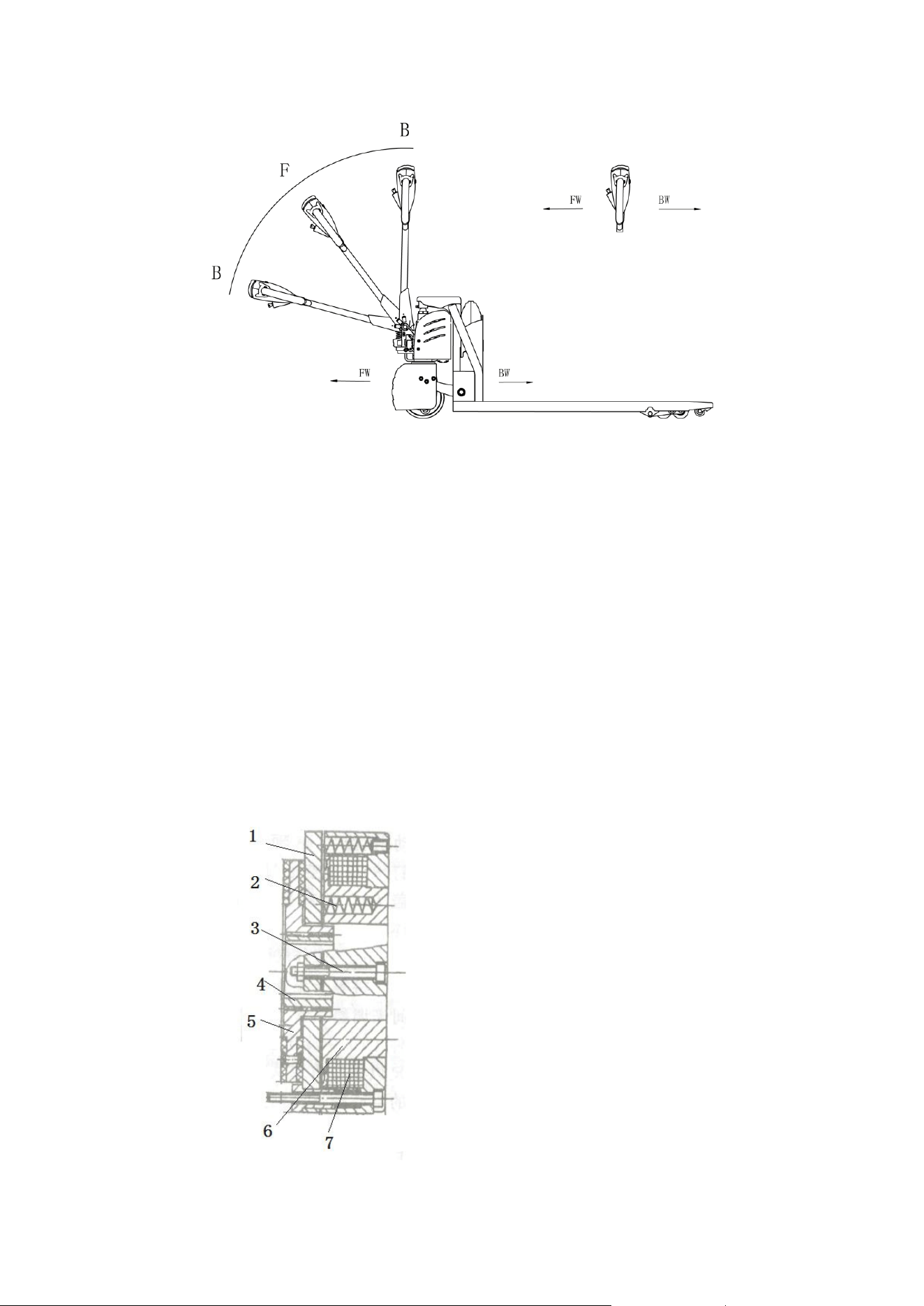
4.Operating principle
The Truck with battery as power producer and controlled by electrical and hydraulic, trucks
can do some actions like walking, turning, pallet fork lift, etc.
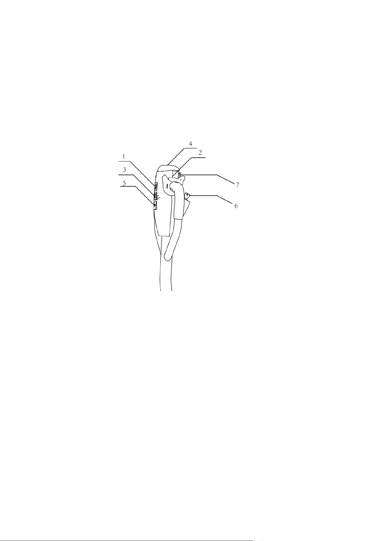
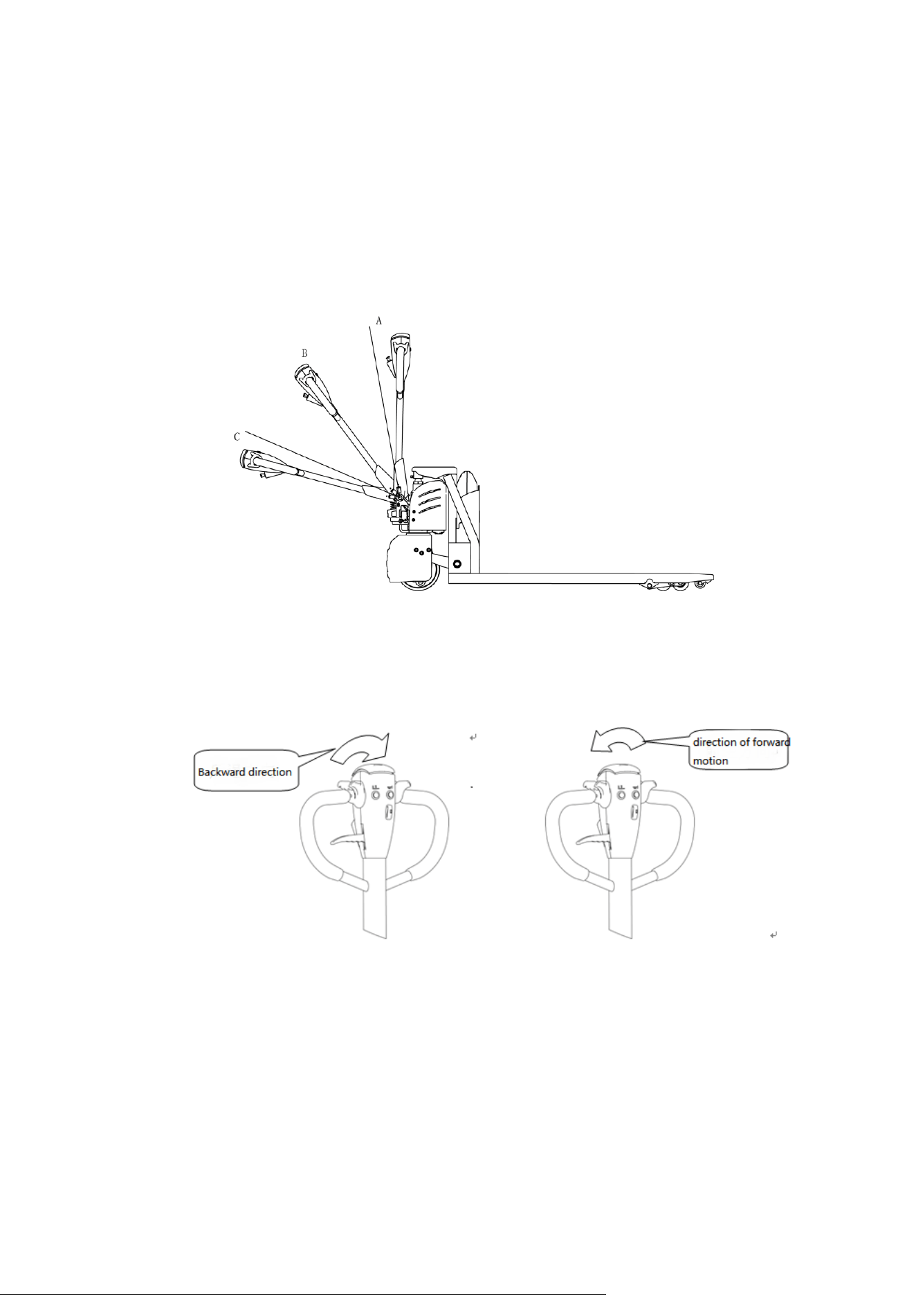
Operating mechanism diagram:
1.Falling knob 2.Driving button 3.Lifting button 4.Emergency Reverse Button
5.Horn 6.Electricity meter 7.Tortoise speed button

7
5.Operating principle
5.1Running system
The truck is powered by a battery, which is realized by controlling the AC motor on the drive
wheel. The speed of walking is realized by frequency conversion control motor speed, which
is controlled by the accelerator.
5.2Steering system
The steering of the moving car is driven by the handle lever through the handle lever to
drive the drive motor to realize the steering.
5.3 Brake structure and brake schematic diagram.
Braking performance depends on road conditions and vehicle load conditions.
5.3.1The brake function can be activated by the following ways:
⚫ Turn the travel switch (2) to "0" position or release the switch to make truck brake until
it stops.
⚫ With the driving switch (2) moving directly from one driving direction to the opposite
direction, the vehicle regenerates the brake until it begins to move in the opposite
direction.
⚫ The handle moves up and down to the braking area (' B ') and the truck brakes.If the
handle is released, the handle automatically moves to the upper braking area (' B ') and
the truck start braking until it stops.
⚫ Emergency Reverse button (4) can prevent the operator will be squeezed, when the truck
is facing an obstacle in (' Fw) direction .The body touch Emergency reverse button and
the truck deceleates or starts to move to (BW) for a distance and then stops .If the handle is
in the operating area and the truck is not moving, please consider that this button is still
working.
8
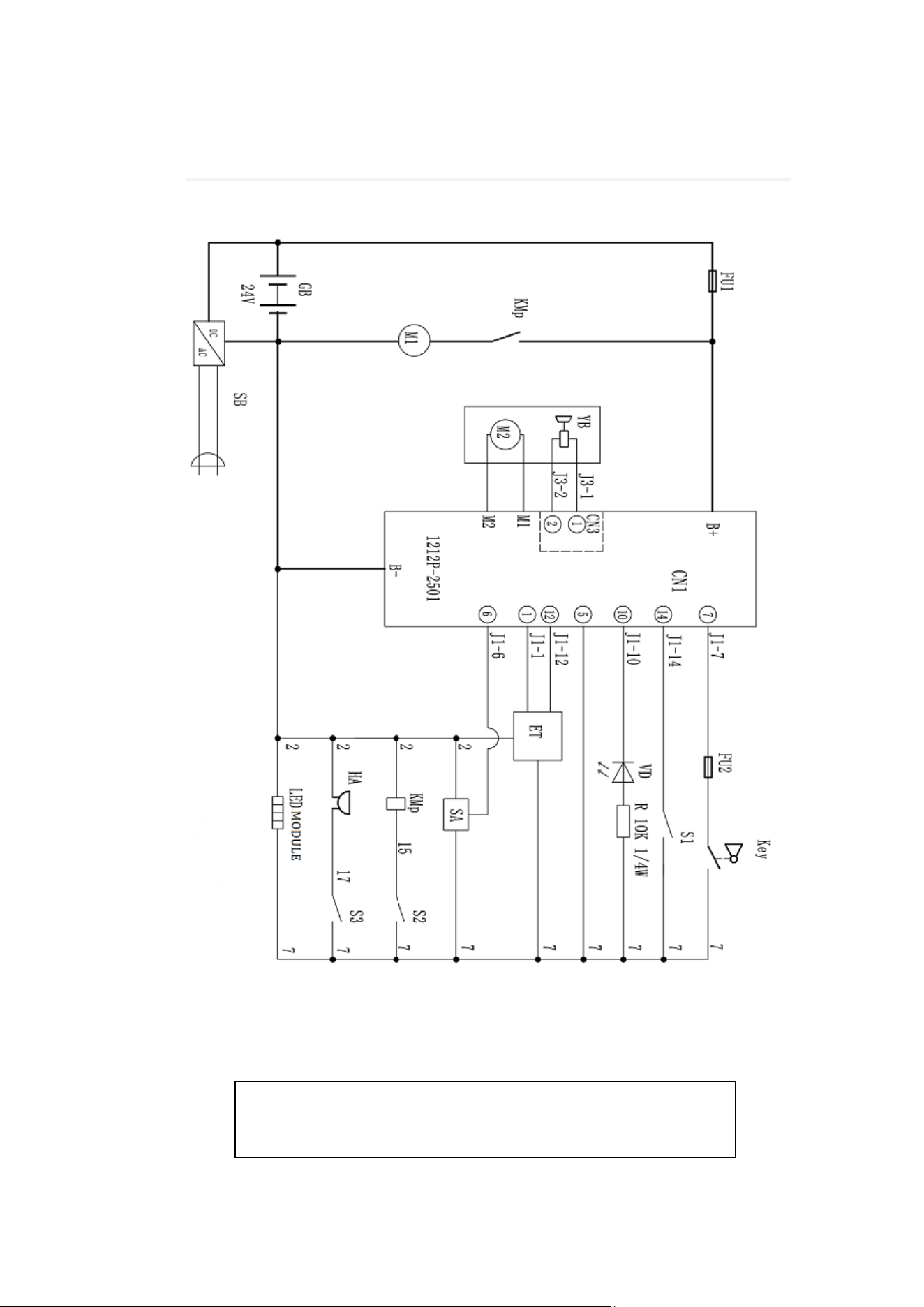
5.3.2Braking operation principle:
As follow picture:The brake constitute by magnetic yoke 6 ,magnet exciting coil,7 , the
spring 2, the brake disc 5,the armature 1, the gear sleeve 4, the mounting screw 3,And so
on .The brake is mounted on the end cap of the motor and the mounting screw is adjusted to the
specified air gap value.
When magnet exciting coil 7 for brake on power,The coil generates a magnetic field to
to attract the armature 1 to the yoke assembly 6, and the armature 1 is disengaged (released)
from the brake disc 5.At this time, the motor drive shaft is normally started and operated
with the brake disc 5.When the magnet exciting coil 7 is de-energized, the magnetic flux
disappears, the armature 1 is released, and the spring 2 is pressed against the armature 1,
and the friction plate on the brake disc is pressed to generate frictional force for braking
purposes.
Brake schematic

9
5.4 Operating System
The main working body of a moving truck is the fork, which relies on a fork to carry the
pallet or cargo for transport and short distance transportation.The expansion of the cylinder
is realized by the control of the operating handle, and the pressure oil is provided by the
pumping station.
5.5 Electric System
The electrical system includes walking and operation control.The truck use DC electric
control assembly.
The meter has a battery indicator.When the battery power is too low, the electric meter will
cut off the starting control line of the oil pump motor. The truck can only walk and can’t lift
the fork,, and the prompt should be charged immediately.
The motor of oil pump is the dc motor for 5 minutes, so the pump motor is not suitable for
long running.That is, the lifting movement should have time interval, can not continuously
carry on, otherwise would make the motor heating, even burn.
Special note: when the truck is used for a long time, the starter of the oil pump motor may
fail, and it can't be broken after being sucked or closed.The latter is not throw control handle,
the oil pump motor is kept in the rotation, should immediately stop at this moment, to cut off
the power supply (unplug battery plug-in), make the oil pump motor stop running, and
promptly replace the starter.
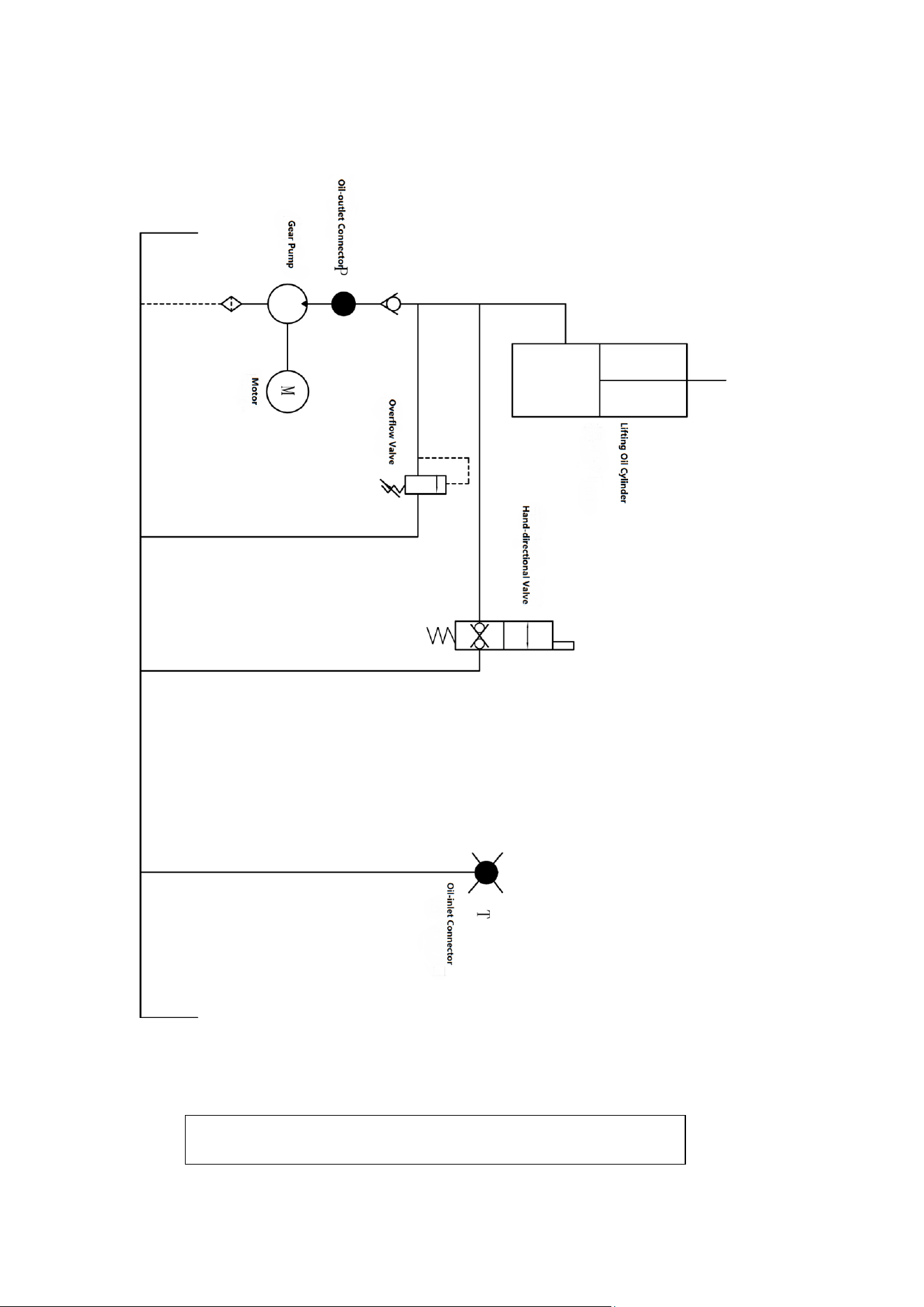
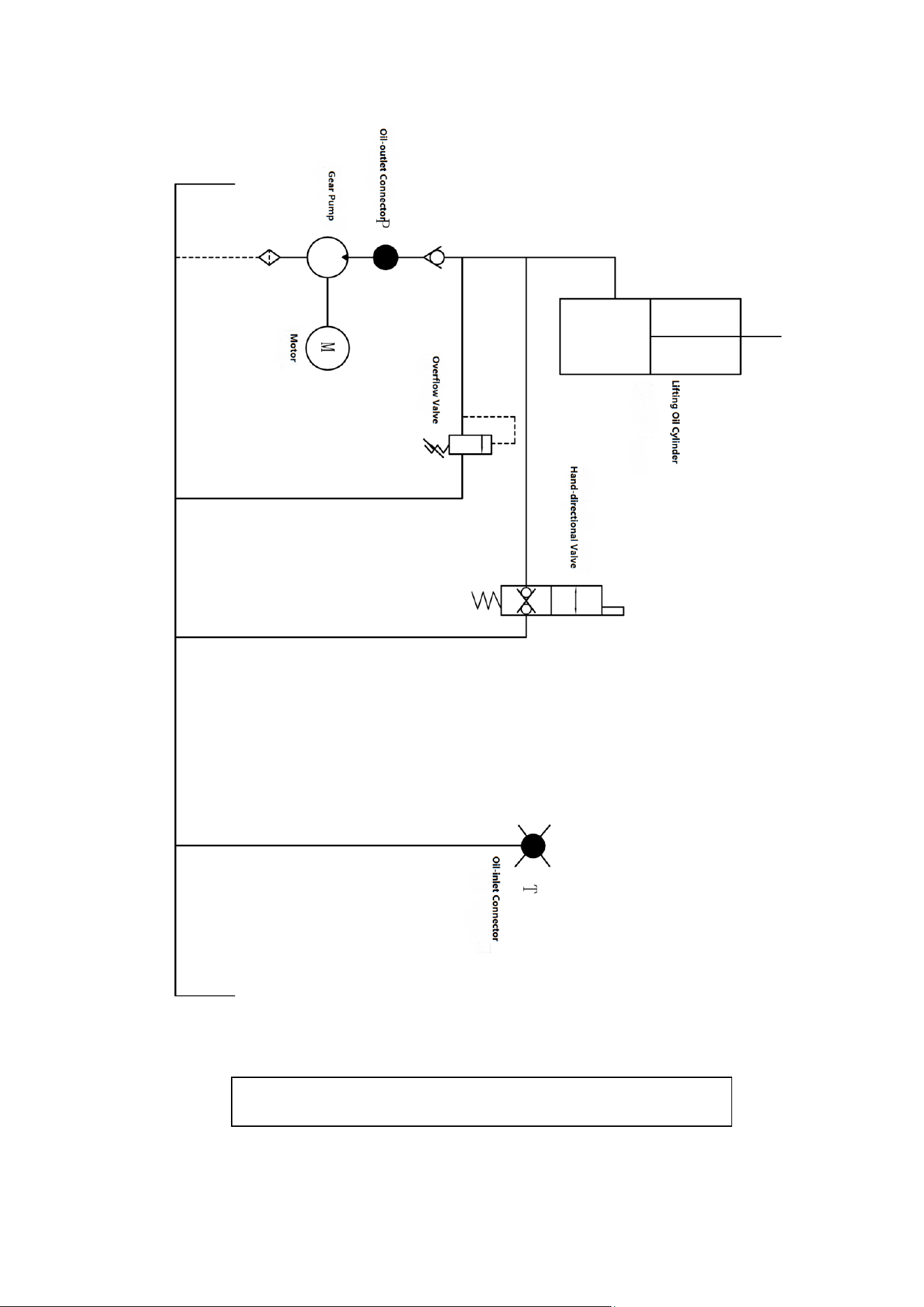
5.6 Hydraulic principle
The oil pump motor drives the gear pump to provide hydraulic power,lifting oil cylinder is
responsible of fork’s lifting and lowering,The control of the lift oil road is controlled by the
buttons on the operating handle,The lifting action is controlled by a single action oil circuit
on the valve block.This model of the hydraulic system pressure can only be adjusted on the
valve block, has been debugging good, before they go out after they leaving our factory,If not
the our company after-sales personnel or professional maintenance personnel are strictly
forbidden to adjust themselves, so as to avoid safety accident.
10
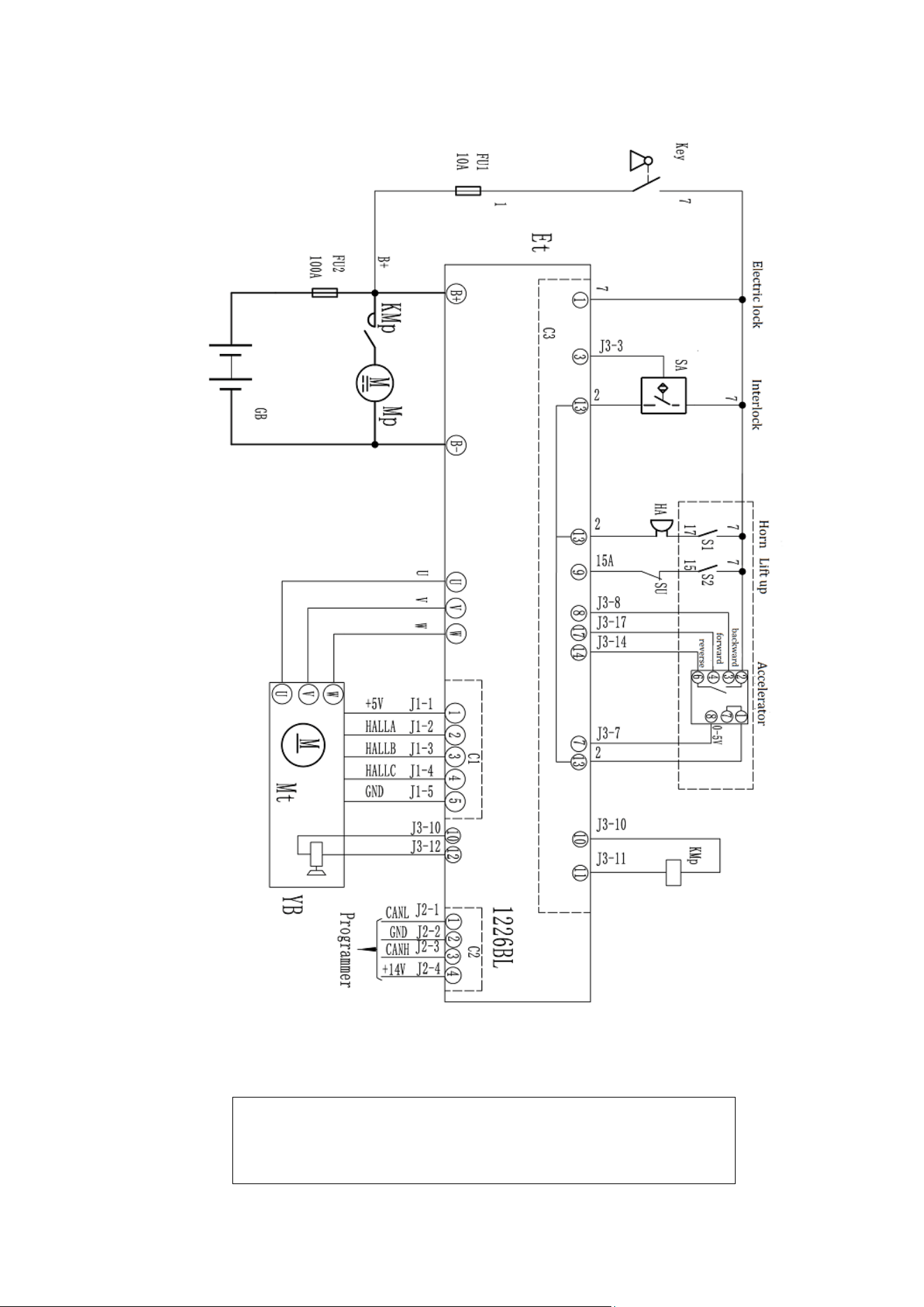
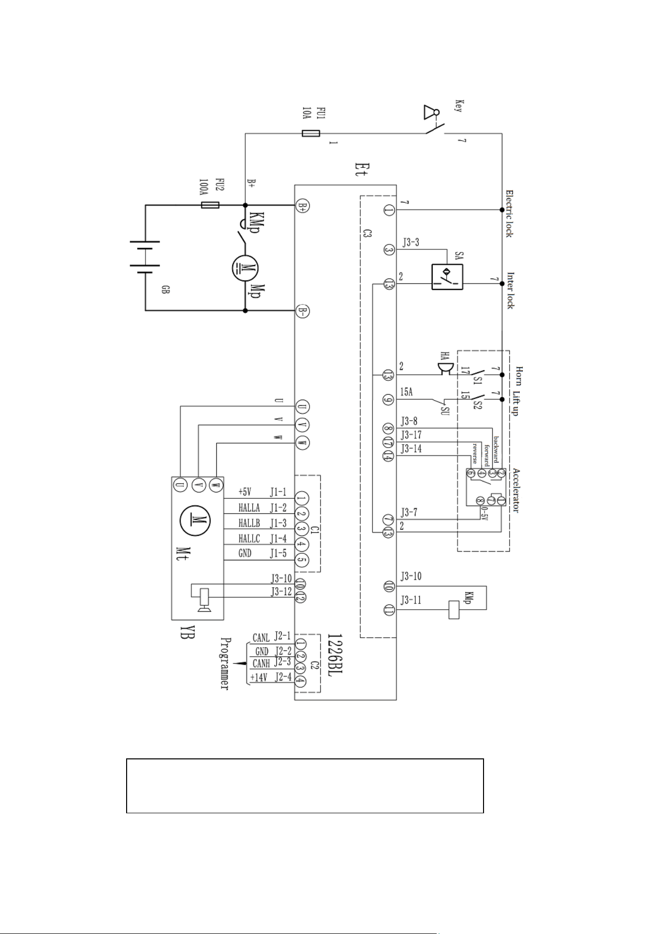
6. Electrical schematic diagram
LPT33 manual lowering
Electrical schematic diagram
11
LPT33 Electric lowering
Electrical schematic diagram
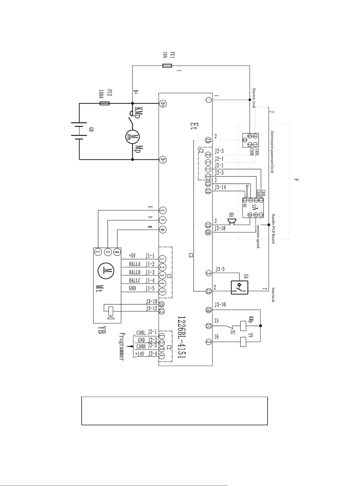
12
LPT33 with REMA Handle
Electrical schematic diagram
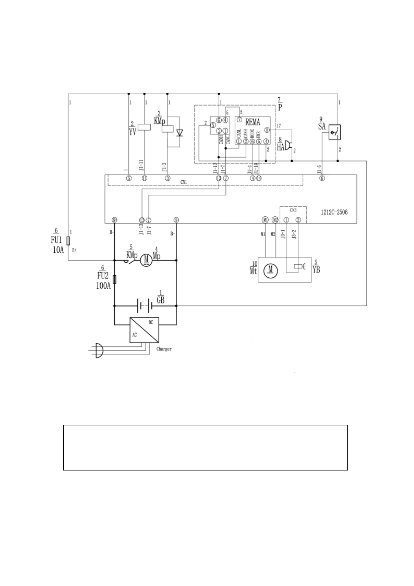
13
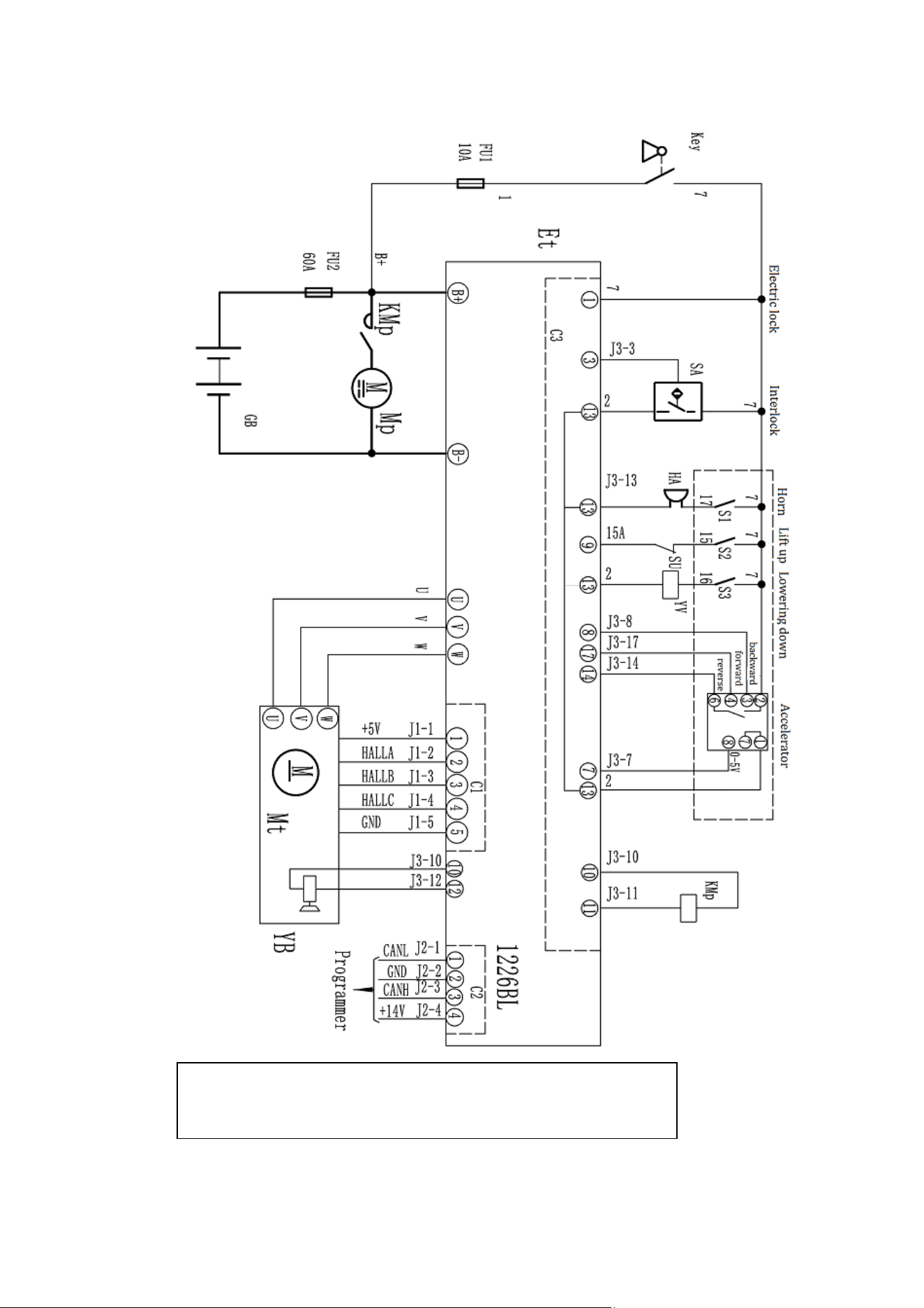
LPT44 Manual lowering
Electrical schematic diagram
14
LPT44 Electric lowering
Electrical schematic diagram
15
LPT44 With REMA handle
Electrical schematic diagram
16
7、Hydraulic Scheme
Manual lowering
17
Electric lowering
18
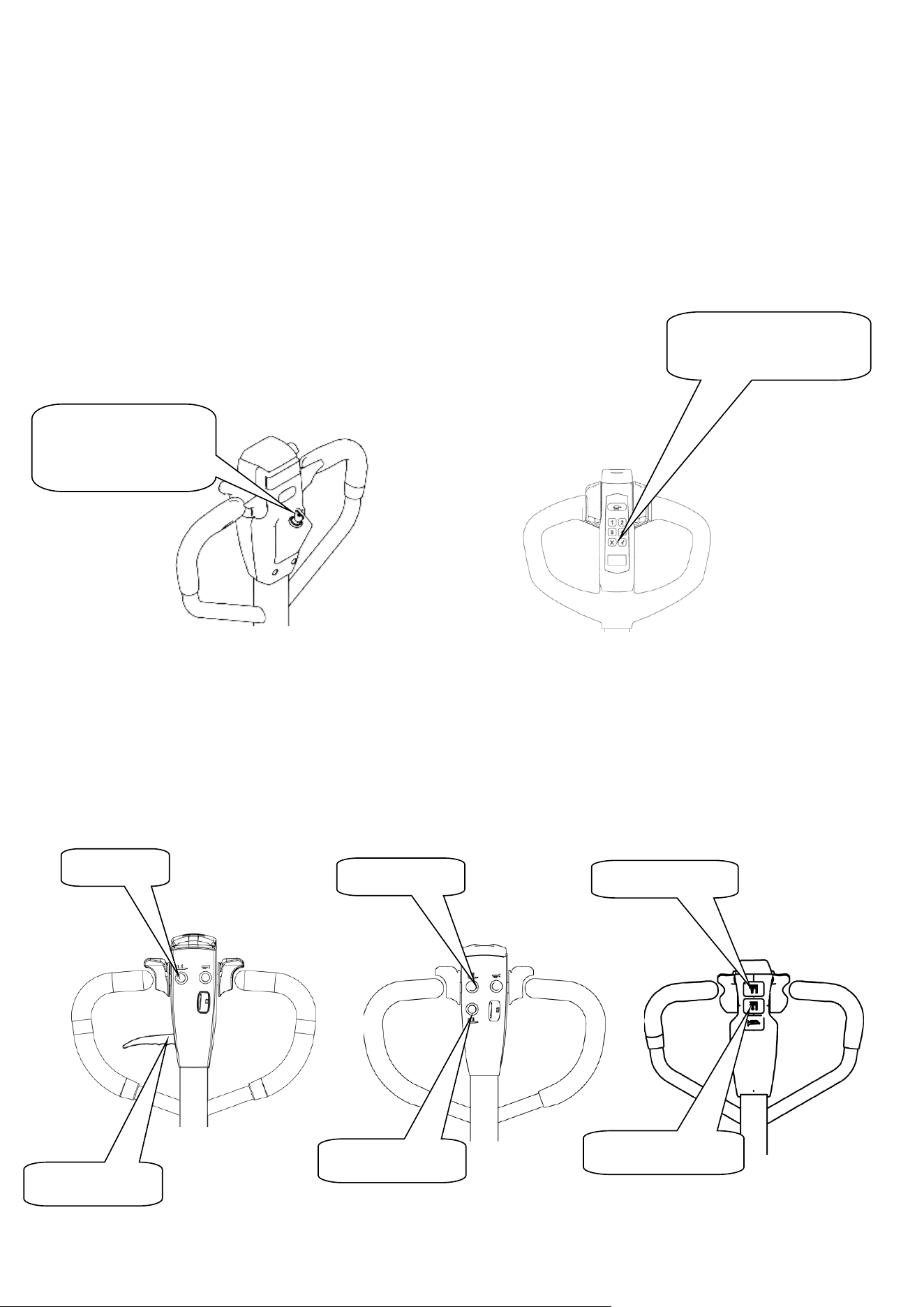
8.Operating Instruction
Before operation, please familiarize yourself with the functions of the switches and buttons
on the dashboard.
8.1 Operation
①、Plug in the lithium battery interface
②、Open the electric lock
③、Fork lifting and lowering:
Lifting:Control the lift button on the handle.
Lowering:Hold the drop knob.
Turn on the electric lock
with the key.
Enter your
password and press ok
Lifting button
Lifting button
Falling button
Falling knob
Falling button
Lifting button
19
④、Driving
Rotate the handle to the driving range;
A and C is brake range;
B is driving range;
Slowly rotate the accelerator to start the truck. (In order to be safe, fast acceleration is
prohibited.)
⑤、Brake
When the accelerator is released normally, the truck will stop until the brake is held in the
car through the regenerative braking of the motor.
When emergency braking, the operating handle is quickly turned to zone A or area C (figure
9), and the brake is carried to the death to realize the emergency braking function.

20
⑥、Parking
Release the acceleration button to stop the moving truck and slow down the truck until the
brakes are on.
Lower the fork to the lowest position. Turn off the electric lock.
Park for a long time, then the battery power cord is pulled out.
8.2Emergency reverse function
The red button at the end of the handle is the emergency reverse button. When the body
is in contact with the emergency reverse button, the truck will stop immediately and drive
backward for a distance. This is a safety switch designed to prevent the vehicle from being
crushed when the operator encounters an obstacle.
8.3 The use of the horn and the reversing horn
In order to drive safely, the truck is equipped with a driving horn. To remind others
when driving, press the horn button in the middle of the handle handle, and the horn will
ring to warn pedestrians.
8.4 Battery capacity display
The battery capacity of the forklift truck on the dashboard has capacity display function.
8.5 Handling stacking operation
(1)How to carry goods
slowly drive the truck to the items to be transported, insert the pallet fork and move
forward slowly, when the goods completely inserted into the goods after parking, control
handle upgrade button, the heavy lifting to a certain height, back slowly, don't touch the
adjacent goods, when the weight zone is put out the goods, and then walk handling.
Emergency reverse button

21
(2)How to place the goods
When moving the goods close to the area of the goods, it will slow down. When the
moving truck is in a straight line with the goods, then the moving truck will slowly move
forward to the loading area to stop. Slowly press the lower lever, and once the load is held,
the fork will be lowered to the hollow position. When the fork is pulled out of the weight, the
back position will be confirmed without any obstacle. Wait for the fork to leave the weight
completely before carrying on a round of handling.

22
9.Safety operation and matters needing attention
The spare parts of the truck is not allowed to change without permission. All parts
supplied by the original manufacturer are subject to strict quality inspection. To ensure the
safety and reliability of the vehicle, please use the original parts. Replacement parts,
including all oils, must be collected and processed in accordance with local environmental
and health laws and regulations.
9.1 Repair and Maintenance
Maintenance technician: The maintenance and service should only be performed by
special personnel trained by the manufacturer. After the technician sent by after-sales
department of the manufacturer completed maintenance and servicing work, they should
sign on the service log.
Lifting of Truck: When the truck needs to be lifted for maintenance, the lifting device must
be safe and reliable, and strictly tied to the location of the lifting point. When the truck is
lifted, appropriate measures must be taken to prevent the vehicle from slipping or tipping
(wedges, wooden blocks can be used).
Cleaning Operation: Flammable liquid can not be used for cleaning the stacker. Before
cleaning, take safety precautions to prevent electric sparks (e.g. sparks caused by short
circuit). When operating the accumulator, connectors on it must be disconnected. Use soft
air suction or compressed air, non-conductive and anti-static brushes to clean electric and
electronic components.
Operation of Electric System: Operation on the electric system should only be performed
by specially trained personnel. Before performing any operation on the electric system,
precautions must be made to prevent electric shock. When operating the accumulator,
connectors on it must be disconnected.
Welding operations: To prevent damage to electrical or electronic components, these
electrical components must be removed from the truck before taking any welding
operations.
Installation: When repairing or replacing hydraulic components, electric and electronic
components, make sure to install them back to their original positions.
Wheels: Quality of the wheels has significant effect on stability and driving performance of
the truck. Modification on wheels can be performed only with the approval from the
manufacturer. When replacing wheels, ensure that the truck is levelled as delivery
state(wheels must be replaced in pairs, i.e. replace right wheel together with left one).

23
Hydraulic oil pipe: The oil pipe must be changed every 6 years. When change the hydraulic
assembled parts, the oil pipe should be also changed.
9.2 Routine Maintenance
9.2.1 check the condition of each pole, cable and protective cover of the accumulator.
9.2.2 check whether the battery box is secure.
9.2.3 check whether the truck is oiled.
9.2.4 check the situation of fork, oil pipe and horn.
9.2.5 check the braking condition.
9.2.6 check the wear condition of driving wheel, load wheel and so on.
9.3 Professional Maintenance Manual
It is very important for safe operation of the truck to perform overall professional
maintenance. Failure in performing maintenance according to specified interval may cause
malfunction of the truck, and potential risk to human and equipment.
Maintenance periods listed in this manual apply to single shift a day under normal operation
conditions. If using in dusty environment, the ambient temperature varies remarkably or in
multi-shift situation, the maintenance period has to be shortened.
Maintain the truck according to following maintenance list. Maintenance periods are as
follows:
W1 = Every 50 work hours, but at least once a week.
M3 = Every 250 work hours, but at least once every three months
M6 = Every 500 work hours, but at least once every six months
M12 = Every 2000 work hours, but at least once every 12 months
Additional operations should be performed in trial run period:
(In initial 50 – 100 working hours or after two months)
— Check the nuts on the wheels, and tighten them if necessary.
— Check the hydraulic components for leakage, and tighten them if necessary.
—Replace the hydraulic filter.

24
Time interval(Month)●
W
A
B
C
Brake
1.1
Check the air gap of the electromagnetic brake
●
Electrical
system
2.1
Check the operation switch to show the function of the device
and components
●
2.2
Check alarm system and safety device
●
2.3
Check the cable for damage and the terminal is secure
●
2.4
Check the function of the micro switch setting
●
2.5
Check controller and EPS controller
●
2.6
Cable and motor fixing
●
Power
supply
3.1
By observing the battery
●
3.2
Visual inspection of battery charging plug
●
3.3
Check if the connection of the battery cable is tight, and if
necessary, apply the electrode with grease.
●
Driving
system
4.1
Check the gearbox for abnormal noise
●
4.2
Check the running mechanism and grease, check the reset
function of the operating handle
●
4.3
Check the drive wheel and bearing wheels for wear and
damage
●
4.4
Check wheel bearings and fixing conditions
●
Whole
frame
5.1
Check if the frame is damaged
●
5.2
Check if the sign is complete
●
5.3
Check the fixing of the mast
●
Hydraulic
movement
6.1
Check the function of the hydraulic system
●
6.2
Check hoses, pipes and connections for tightness, sealing and
damage
●
6.3
Check the cylinder and piston for damage, sealing and fixing
●
6.4
Check the load chain settings and re-tension if necessary
●
6.5
Visually inspect the mast rollers and check the wear on the
roller faces
●
6.6
Check the forks and load handlers for wear and loss
●
6.7
Check the tank for oil level
●
6.8
Update hydraulic oil
●
Maintain list

25
9.4 Battery maintenance, charging and maintenance.
Any operation of the battery must be guaranteed to stop the truck and put it in a safe
position.
9.4.1 maintenance personnel.
Battery charging, maintenance and replacement must be operated by qualified professionals.
You must carefully read the manual, supply preparation and charging requirements before
preparing for the operation.
9.4.2 fire protection measures.
Smoking and open fire are strictly prohibited when operating the battery. Storage battery
and charge must be kept away from combustible materials, at least 2 meters above the
distance, the place of storage battery must be well ventilated and equipped with fire-fighting
facilities.
9.4.3 Battery type and usage note.
①、The battery type of the car is: lithium ion battery; Battery voltage 24V/48V;This
battery belongs to environmental protection battery, without chemical mercury and
cadmium.
②、Matters needing attention:
A) the battery USES the temperature environment 5 ~ 45;
B) the battery shall be charged and discharged once every three months during the long
period of suspension;
C) before using the new battery, or for the first time after storage, please recharge the
battery before use;
D) do not short-circuit the battery, which may permanently damage the battery;
E) do not burn or destroy batteries, which may cause the release or explosion of toxic
gases;
F) do not directly weld the battery;
G) do not allow the battery to be in a hostile environment, such as extreme temperature,
deep cycle, or frequent overcharge/discharge;
H) if the battery is hot, do not touch, until cooling;

26
I) when removing the battery pack, hold the plug with your hand instead of pulling the
cord;
J) after the battery is used, if the battery is hot and before recharging, please cool in the
ventilated environment;
K) do not put batteries in water or seawater;
L) do not try to separate, squeeze, impact the battery, the battery will heat or fire, the
lye in the battery will be harmful to the skin and eyes, and will damage the clothes;
M) keep the battery away from children.
9.4.4 Disposal of used batteries
Scrap battery must be carried out in accordance with the relevant laws and regulations in
region recycling, storage provisions stipulated by the environmental protection area or
waste treatment area, and the work must be conducted by qualified professional company.
9.4.5 Specification of the battery
Uninsulated terminal poles on the accumulator should be protected with an insulated cover.
When connecting the accumulator and socket, make sure to stop the device and put the
switch at position “0”.When replace or install the accumulator, make sure the accumulator is
fixed securely in battery box.
9.4.6 Storage, transportation and installation of the accumulator
The device must be parked on the level ground steadily. To prevent short circuit,naked cable
ends and the terminal posts should be covered with insulated covers. When pulling out the
accumulator, properly arrange removed accumulator's connectors and cables without
blocking access of the accumulator.
9.4.7 Battery power indicator
Battery power display table:ten article showing represent 100% of the battery.
With the consumption of battery capacity, the glowing article shows will be from top to
down.

27
The color of LED show the different states:
Name
LED Color
Parameter value
The standard battery
remaining power
Green
70-100%
Orange
30-60%
Red blinking
0-20%
Battery discharge on 70%, red lamp will blinking “Energy storage”.
Battery discharge on 80%, two lamp will blinking “run out of battery”, Need to charge the
accumulator.
9.4.8 Charging
Read the instruction manual carefully before recharging.
a)Must use Li-ion Charger specially designed by our company
b)Do not reverse charge the battery
c)Stop charging immediately when battery has obvious heat during charging .Then cool
it before charging
d)Please hold the handle when pulling charger connector, direct drawing of wire is not
allowed
9.4.9Disassembly and Installation of battery
Parking the truck before the battery is removed and installed
Disassembly & Installation battery step:
A:Turn off the car 。
B:Pull the power connector handle and unplug the power connector(Attention: When
pulling the power connector, Must hold the handle .Please do not pull the wire directly
C: Pull up the battery and pull the battery out of the car.
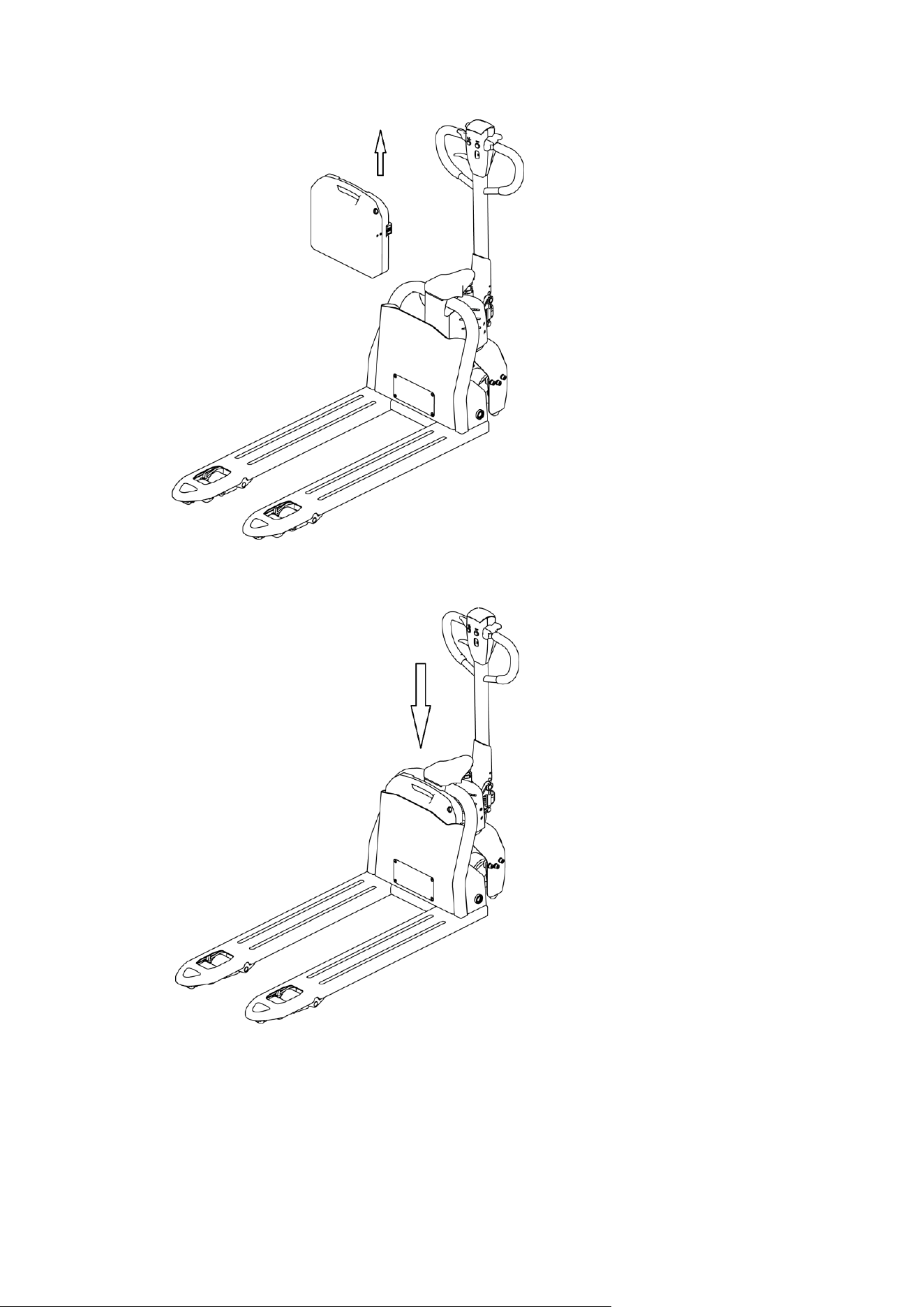
28
D:Insert the new battery into the battery mounting slot
.
E:Plug in the power connector.
29
10.Safety Caution
10.1 General rule
10.1.1 The operator must have a forklift operation qualification which proved by the
relevant departments of the training before driving truck.。
10.1.2 The operator must read the instructions before use all of the content, after fully
understand operation method can drive Truck.
10.1.3 truck must not carry passengers.。
10.1.4 Operators should pay special attention to when homework operating environment,
including other people nearby and fixed object.
10.1.5 Without the manufacturer's approval, shall not modify, add or remove tractor parts,
lest affect performance of tractor.
10.2 Storage and transportation
10.2.1 Use container or car to transport the truck should pay attention to at the time of
shipment:
○
1 Front and rear wheels with wedge, begin to pull up the parking system, prevent
sliding in the process of transportation;
○
2 Using the lasso, not placed in the weak structure of the truck;

30
○
3 When moving the truck. Pay attention to keep the center of the moving truck in the
middle of two fork
○
4 During Transportation, Remove the Trailer and fix the tractor with a dedicated
strap for lifting according to the figure below。
10.2.2 When Truck doesn't work, should be parked in a dry ventilated cleaning warehouse,
Protect the truck from the sun and rain
And please note:
○
1 Turn off the Electrical lock and make the safety switch off, unplug the power plug
○
2 Begin to pull up the parking system, front and rear wheels with block mat;;
○
3 Such as discontinued for a long time, battery should be added once every 15 day
electricity.
10.3 Check before using
10.3.1 New car if there is any damage in transportation, please don't be put into use, and
promptly get in touch with the supplier, do proper processing.
10.3.2 New cars in the factory run parts has been filling lubricating oil.
10.3.3 Truck equipped with battery.The battery is charged before leaving factory.If leaving
the factory for a long time, may the battery is low.Before use should pay attention to
electricity meter shows that when the electricity meter display to the last two warning, must
charge at once.
10.4Safety operation regulation
10.4.1Requirement for operator: The Truck must be operated by a trained operator, He
can perform and operation demonstration on the user to move and mainpulate the cargo,
and can clearly guide the user how to operate the forklift.
10.4.2 Operator’s rights, obligations and responsibilities:Has been trained by the
operation of the vehicle, the driver must be clear of his rights and obligations; and he is
familiar with the contents of the relevant operating instructions. If the vehicle is pedestrian
type, the driver must also wear safety boots.

31
10.4.3 Prohibit unauthorized person to operate:The operator is responsible for the
vehicle,he need to prohibit unauthorized person to operate. Transport or lift person is also
forbidden.
10.4.4 Malfunctions and defects:If the vehicle has any malfunctions or defects,need to
inform administrator, If the vehicle cannot be safely operated (e.g.: wheel wear or brake
failure), then it must stop using until it is fully repaired.
10.4.5 Safe operation and environmental protection:inspection and maintenance must
be performed in accordance with the time intervals on the maintenance list.
Parts of the vehicle cannot be changed without any permission, especially safety devices. The
operating speed of the truck is not allowed to change.
All original spare parts have been verified by quality assurance department. To ensure the
safety and reliability of the operation of the truck must use only the manufacturer's spare
parts. The old parts, such as oils and fuels must be handled in accordance with the relevant
environmental protection rules.
10.4.6 Hazardous area: Hazardous area usually refers to the following range: vehicle or its
load lifting devices (e.g. fork or accessories) is dangerous for personnel when running or
lifting movements, or the ongoing regional transport loads. Typically, this range extends to
the load or truck accessories landing area.
Unauthorized personnel must be asked to leave the dangerous zone. As long as the situation
might cause some kind of damage, the driver must give a warning, if the driver asked the
person to leave but did not leave the hazardous zone, the driver must immediately stop the
vehicle.
10.4.7 High-risk environment:Working in high-risk environment, operator must have a
special design to be protected.
The vehicle was not specially designed for the high-risk environment.

32
10.4.8 Safety devices and warning signs: Safety devices, warning signs and warning notes
described in the previous operating instructions must be taken seriously enough.
10.4.9Driving in public places: the vehicle is forbidden to drive in public places expect in
specified special areas.
10.4.10Distance between truck: keep an appropriate distance, avoid the front vehicle
suddenly stop.
10.4.11headroom: When the headroom is below the cargo or mast, it is forbidden to use
the vehicle.
10.4.12Using in the elevator and loading platform maneuvering: if there is sufficient
loading capacity, won’t affect the operation of the vehicle, and being agreed by the operator
of the vehicle, then the elevator and loading platform can be used for vehicle transport.
Before entering the elevator or loading station, operator must personally identify. The goods
must be placed in front and occupy an appropriate place, to avoid touching the wall of the
elevate when the vehicle enters the elevator. When personnel and vehicles take the elevator
together, person can enter only after the vehicle has safely entered, and person must leave
before the vehicle.
10.4.13 Driving aisle and working area: The vehicle must be operated on the specified
aisle, all non-related person must leave the work area, and cargo should be stacked in
designated places.
10.4.14 Operation Management:Driving speed must be adapted to local conditions. When
through the corners, narrow passage, swing doors and closed place, speed must be slowed
down. Drivers must be able to visually an adequate braking distance between vehicle and the
front vehicle, and he must remain in control of his vehicle. Sudden stop (unless urgent
needs), rapid U-turn, chased each other in the Aisle is not allowed. Do not pry out of the body
to operate the vehicle.
10.4.15 Visibility: The driver must look attentively at the direction of driving, to ensure the
front situation is clearly visible. When the vehicle is backing off, if the carriage of goods block

33
the line of sight, a second person walk in front of the vehicle to give appropriate guidance
and warnings is necessary.
10.4.16 Pass through the ramp: Only a known ramp which should be clean, non-slip, and
with the vehicle technical availability was allowed to go through. The goods on the forks
must face uphill. It is forbidden to turn back, move diagonally or park on the ramp. The
operator must slow down when going through the ramp, and prepare to brake at any time.
10.4.17 Load capability on ground: when the vehicle is in operation, make sure the load
pressure of the body weight or wheels on the ground does not exceed the load capacity of the
ground.
10.4.18 Vehicle Change: Any possible changes or modifications for rated load, stability or
safe operation of the vehicle, must obtain prior written approval from origin manufacturers
or its successor. After vehicle manufacturer check and approve the changes, nameplates,
labels and markings of Operation and Maintenance Manual must be modified as well.

34
11.Service Manual
11.1 Troubleshooting
Fault
Cause
Treatment
The truck can't
move
The battery connector is not connected
Check the battery connector,connected if
necessary
Electric lock switch on “OFF” position
Electric lock switch turn to “0”position
Emergency Stop Switch not open
Open the Emergency stop switch
Battery power runs out
Check the battery charge,If it is
necessary to recharge
The vehicle being charge
Interrupt charging process
The fuse is damaged
Check the fuse
Goods can’t be
lifted up
The vehicle is not operating
Handle according to the treatment
method listed in Vehicles cannot move”
Low hydraulic oil level
Check hydraulic oil
The fuse is damaged
Check the fuse
Overloading
Pay attention to the rated capacity
The Up switch is in bad contact or
damaged
Check up switch and replace if necessary
Goods can’t be
lowered down
Dirty oil blocks control valve
Check hydraulic oil and clean control
valve,replace the oil if necessary
The solenoid valve for lowering is not
opened or is damaged
Check or replace the valve for lowering
Can’t stop when
lifting
Lifting micro switch is damaged
Cu off the power and replace lifting micro
switch
Moving in one
direction
The sensitive switch and the
connecting cable are not
well-contacted.
Check the sensitive switch in control
lever and the connecting cable.
The vehicle travels
very slow
The related cable are not
well-connected
Check the battery indicator light and
related cable
The car suddenly
started
Controller is damaged.
Change the controller
The handle which control the forward
or back is no reset.
Repair or change

35
If above steps still can not solve problems, please contact after-sales service department of
the manufacturer and have the problems solved by specially trained technicians.
11.2 Preparation before repair
To prevent possible accidents during maintenance and repair work, following preparations
must be done:
— Park the device safely.
— Press the emergency stop switch and disconnect the connectors on accumulator.
11.3Check the amount of hydraulic oil
— A vehicle ready for repair or maintenance。
— Open the electrical box cover。
— Check the amount of hydraulic oil in the tank。
When checking the hydraulic oil level, the fork and mast must be lowered to the lowest
position.
11.4 Complete repair, the preparation before using
Use the device only after following operations have been completed.
— Clean the vehicle
— Check the brake.
— Check the emergency stop switch.
— Check the horn.
Several electromagnetic brake tests need perform immediately after the test