INSTRUCTION MANUAL
MANUAL DE INSTRUCCIONES
Cordless Backpack Vacuum Cleaner
Aspiradora de mochila a batería
GCV08
IMPORTANT: Read Before Using.
IMPORTANTE: Lea antes de usar.
2 ENGLISH
ENGLISH (Original instructions)
SPECIFICATIONS
Model: GCV08
Capacity Filter bag 6.0 L (1.6 gal.)
Dust bag 5.5 L (1.5 gal.)
Maximum air volume
(With hose ø32 mm (1-1/4″) x 1.0 m (39-3/8″))
2.4 m
3
/min (84.8 cu.ft/min)
Vacuum 20 kPa
Dimensions (L x W x H)
(excluding the harness, with BL4050F)
336 mm x 185 mm x 543 mm
(13-1/4″ x 7-1/4″ x 21-3/8″)
Rated voltage D.C. 36 V - 40 V max
Net weight 6.4 - 9.5 kg (14.1 - 20.9 lbs)
• Due to our continuing program of research and development, the specications herein are subject to change
without notice.
• Specications may dier from country to country.
• The weight does not include accessories but battery cartridge(s). The lightest and heaviest combination weight
of the appliance and battery cartridge(s) are shown in the table.
• The length of supplied hose varies depending on the countries.
Applicable battery cartridge and charger
Battery cartridge BL4020 / BL4025 / BL4040 / BL4040F / BL4050F / BL4080F
Charger DC40RA / DC40RB / DC40RC
• Some of the battery cartridges and chargers listed above may not be available depending on your region of
residence.
WARNING: Only use the battery cartridges and chargers listed above. Use of any other battery cartridges
and chargers may cause injury and/or re.
WARNING: Do not use a corded power supply such as battery adapter or portable power pack with
this appliance. The cable of such power supply may hinder the operation and result in personal injury.
SAFETY WARNINGS
IMPORTANT SAFETY
INSTRUCTIONS
When using an electrical appliance,
basic precautions should always be fol-
lowed, including the following:
READ ALL
INSTRUCTIONS
BEFORE USING
THIS APPLIANCE.
WARNING
To reduce the risk of re, electric shock
or injury:
1. Do not leave appliance when battery
tted. Remove battery from appli-
ance when not in use and before
servicing.
2. Do not use on wet surfaces. Do not
expose to rain. Store indoors.
3. Do not allow to be used as a toy.
Close attention is necessary when
used by or near children.
4. Use only as described in this man-
ual. Use only manufacturer's recom-
mended attachments.

3 ENGLISH
5.
Do not use with damaged battery.
If appliance is not working as it
should, has been dropped, dam-
aged, left outdoors, or dropped into
water, return it to a service center.
6. Do not handle appliance with wet
hands.
7. Do not put any object into open-
ings. Do not use with any opening
blocked; keep free of dust, lint, hair,
and anything that may reduce air
ow.
8. Keep hair, loose clothing, ngers,
and all parts of body away from
openings and moving parts.
9. Turn o all controls before removing
the battery cartridge.
10. Use extra care when cleaning on
stairs.
11. Do not use to pick up ammable or
combustible liquids, such as gaso-
line, or use in areas where they may
be present.
12. Do not pick up anything that is burn-
ing or smoking, such as cigarettes,
matches, or hot ashes.
13. Do not use without dust collecting
bag in place.
SAVE THESE
INSTRUCTIONS.
This appliance is intended for commer-
cial use.
Battery tool use and care
1. Prevent unintentional starting.
Ensure the switch is in the o-po-
sition before connecting to battery
pack, picking up or carrying the
appliance. Carrying the appliance with
your nger on the switch or energiz-
ing appliance that have the switch on
invites accidents.
2. Disconnect the battery pack from
the appliance before making any
adjustments, changing accessories,
or storing appliance. Such preventive
safety measures reduce the risk of
starting the appliance accidentally.
3. Recharge only with the charger
specied by the manufacturer. A
charger that is suitable for one type of
battery pack may create a risk of re
when used with another battery pack.
4. Use appliances only with speci-
cally designated battery packs. Use
of any other battery packs may create
a risk of injury and re.
5. When battery pack is not in use,
keep it away from other metal
objects, like paper clips, coins,
keys, nails, screws or other small
metal objects, that can make a
connection from one terminal to
another. Shorting the battery terminals
together may cause burns or a re.
6. Under abusive conditions, liquid
may be ejected from the battery;
avoid contact. If contact acciden-
tally occurs, ush with water. If liq-
uid contacts eyes, additionally seek
medical help. Liquid ejected from the
battery may cause irritation or burns.
7.
Do not use a battery pack or appli-
ance that is damaged or modied.
Damaged or modied batteries may
exhibit unpredictable behavior result-
ing in re, explosion or risk of injury.
8. Do not expose a battery pack or
appliance to re or excessive tem-
perature. Exposure to re or tem-
perature above 130 °C may cause
explosion.
9. Follow all charging instructions
and do not charge the battery
pack or appliance outside of the
temperature range specied in the
instructions. Charging improperly or
at temperatures outside of the speci-
ed range may damage the battery and
increase the risk of re.
10. Have servicing performed by a
qualied repair person using only
identical replacement parts. This will
ensure that the safety of the product is
maintained.
11. Do not modify or attempt to repair
the appliance or the battery pack
except as indicated in the instruc-
tions for use and care.

4 ENGLISH
ADDITIONAL
SAFETY RULES
1. Read this instruction manual and
the charger instruction manual care-
fully before use.
2. Do not vacuum the following:
• Flammable liquid (kerosene,
gasoline, solvents such as ben-
zine, thinner, etc.)
•
Hot substances that are burning
or smoking (cigarettes, matches,
incense sticks, candles, hot ashes),
sparks and metal dust generated by
cutting or grinding metal, etc.
• Flammable material (toner,
paint, spray, etc.)
•
Foam like carpet cleaning agent, etc.
(they may cause explosion or re)
• Explosive or pyrophoric sub-
stances (nitroglycerin, alumi-
num, magnesium, titanium, zinc,
red phosphorus, yellow phos-
phorus, celluloid, etc. and their
dust, gas or steam)
• Sharp objects (glass, cutlery,
wood splinter, metal, stone, nail,
razor, push pin, etc.)
•
Solidifying and conductive ne
powder (metal or carbon powder)
• Dehumidier
• Large amount of powder (our,
re extinguisher powder, etc.)
• Substances that cause toxic
symptoms
•
Aggressive chemicals (acid, alkali, etc.)
• Liquid or damp garbage, includ-
ing vomit and excreta
• Asbestos
• Pesticides
Such action may cause re, injury
and/or property damage.
To reduce your exposure to these
chemicals, always wear approved
respiratory protection such as dust
masks that are specially designed
to lter out microscopic particles.
Direct the exhaust air away from
your face and body.
NOTE: Read the OSHA regulation
on silica dust to understand the
requirements needed to reduce
exposure to silica dust at the job-
site. Specic rules apply to the drill-
ing, demolition cutting and grinding
materials that contain silica. All
OSHA requirements regarding
reducing silica dust can be found at
the OSHA website: www.osha.gov.
3. Stop operation immediately if you
notice anything abnormal.
4. If you drop or strike the cleaner,
check it carefully for cracks or dam-
age before operation.
5. Do not bring close to stoves or other
heat sources.
6. Do not block the intake hole or vent
holes.
Symbols
The followings show the symbols used for tool.
volts
direct current
Important safety
instructions for
battery cartridge
1. Before using battery cartridge,
read all instructions and cautionary
markings on (1) battery charger,
(2) battery, and (3) product using
battery.
2. Do not disassemble or tamper with
the battery cartridge. It may result in
a re, excessive heat, or explosion.
3. If operating time has become
excessively shorter, stop operating
immediately. It may result in a risk
of overheating, possible burns and
even an explosion.
4. If electrolyte gets into your eyes,
rinse them out with clear water and
seek medical attention right away. It
may result in loss of your eyesight.

5 ENGLISH
5.
Do not short the battery cartridge:
(1) Do not touch the terminals with
any conductive material.
(2) Avoid storing battery cartridge
in a container with other metal
objects such as nails, coins, etc.
(3) Do not expose battery cartridge
to water or rain.
A battery short can cause a large
current ow, overheating, possible
burns and even a breakdown.
6. Do not store and use the tool and
battery cartridge in locations where
the temperature may reach or
exceed 50 °C (122 °F).
7. Do not incinerate the battery car-
tridge even if it is severely damaged
or is completely worn out. The bat-
tery cartridge can explode in a re.
8. Do not nail, cut, crush, throw, drop
the battery cartridge, or hit against a
hard object to the battery cartridge.
Such conduct may result in a re,
excessive heat, or explosion.
9. Do not use a damaged battery.
10. The contained lithium-ion batteries
are subject to the Dangerous Goods
Legislation requirements.
For commercial transports e.g. by
third parties, forwarding agents,
special requirement on packaging
and labeling must be observed.
For preparation of the item being
shipped, consulting an expert for
hazardous material is required.
Please also observe possibly more
detailed national regulations.
Tape or mask o open contacts and
pack up the battery in such a man-
ner that it cannot move around in
the packaging.
11. When disposing the battery car-
tridge, remove it from the tool and
dispose of it in a safe place. Follow
your local regulations relating to
disposal of battery.
12. Use the batteries only with the prod-
ucts specied by Makita. Installing
the batteries to non-compliant products
may result in a re, excessive heat,
explosion, or leak of electrolyte.
13. If the tool is not used for a long
period of time, the battery must be
removed from the tool.
14. During and after use, the battery
cartridge may take on heat which
can cause burns or low temperature
burns. Pay attention to the handling
of hot battery cartridges.
15. Do not touch the terminal of the tool
immediately after use as it may get
hot enough to cause burns.
16. Do not allow chips, dust, or soil
stuck into the terminals, holes, and
grooves of the battery cartridge. It
may cause heating, catching re, burst
and malfunction of the tool or battery
cartridge, resulting in burns or personal
injury.
17. Unless the tool supports the use
near high-voltage electrical power
lines, do not use the battery car-
tridge near a high-voltage electrical
power lines. It may result in a mal-
function or breakdown of the tool or
battery cartridge.
18. Keep the battery away from
children.
SAVE THESE
INSTRUCTIONS.
CAUTION: Only use genuine Makita batteries.
Use of non-genuine Makita batteries, or batteries that
have been altered, may result in the battery bursting
causing res, personal injury and damage. It will
also void the Makita warranty for the Makita tool and
charger.
Tips for maintaining maximum
battery life
1. Charge the battery cartridge before completely
discharged. Always stop tool operation and
charge the battery cartridge when you notice
less tool power.
2. Never recharge a fully charged battery car-
tridge. Overcharging shortens the battery
service life.
3. Charge the battery cartridge with room tem-
perature at 10 °C - 40 °C (50 °F - 104 °F). Let
a hot battery cartridge cool down before
charging it.
4. When not using the battery cartridge, remove
it from the tool or the charger.
5. Charge the battery cartridge if you do not use
it for a long period (more than six months).
6 ENGLISH
FUNCTIONAL DESCRIPTION
CAUTION: Always be sure that the appliance
is switched o and the battery cartridges are
removed before adjusting or checking function on
the appliance.
Installing or removing battery cartridge
CAUTION:
Always switch o the appliance
before installing or removing of the battery cartridge.
CAUTION: Hold the appliance and the bat-
tery cartridge rmly when installing or removing
battery cartridge. Failure to hold the appliance and
the battery cartridge rmly may cause them to slip o
your hands and result in damage to the appliance and
battery cartridge and a personal injury.
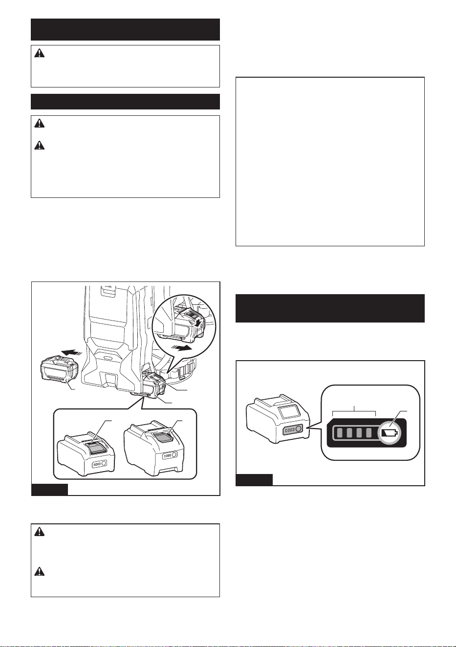
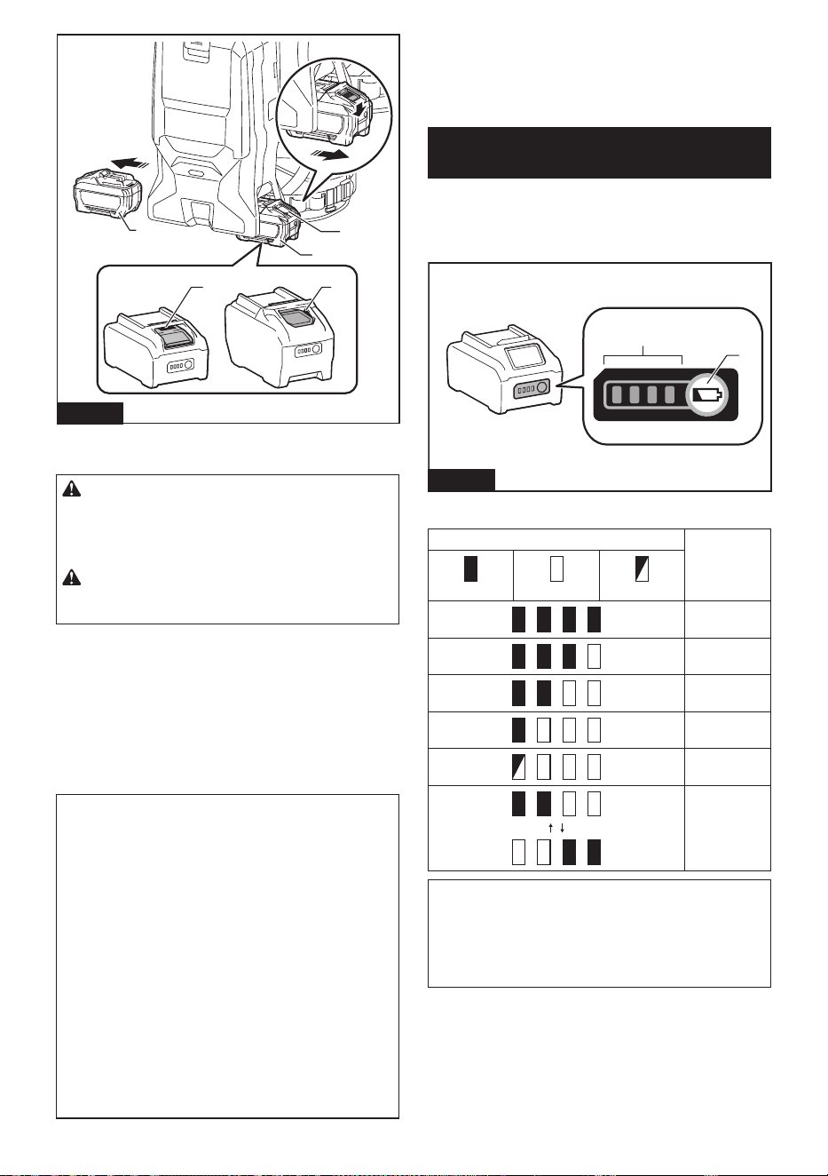
To install the battery cartridges, align the tongues on the
battery cartridges with the grooves in the housing and slip
them into place. Insert them all the way until they lock in
place with a little click. If you can see the red indicators as
shown in the gure, they are not locked completely.
To remove the battery cartridges, slide them out of the
battery housing while pressing and holding the buttons
in front of the cartridges.
2
3
4
11
Fig.1
► 1. Red indicator 2. Button 3. Right battery cartridge
4. Left battery cartridge
CAUTION: Always install the battery cartridge
fully until the red indicator cannot be seen. If not,
it may accidentally fall out of the appliance, causing
injury to you or someone around you.
CAUTION: Do not install the battery cartridge
forcibly. If the cartridge does not slide in easily, it is
not being inserted correctly.
The cleaner has double battery slots. You can choose with either
double batteries or single battery according to your needs.
With double batteries
Continuous drive with two batteries allows longer run-
time and more ecient cleaning. When the rst battery
is becoming empty, the cleaner automatically switches
a power source, so it continues working with the second
battery.
NOTE: The right battery slot (when facing the front
of the cleaner) has priority over the left battery slot.
The left battery slot will only be identied as a power
source, either when no battery is installed in the right
battery slot or the battery in the right battery slot
becomes empty.
NOTE: You can remove the battery from the right
battery slot and recharge it after the cleaner has
switched its power source from the right battery
slot to the left without ceasing operation. To give
priority back to the right battery slot after installing a
recharged battery, restart the cleaner.
NOTE: When the cleaner switches the power source
from the rst battery to the second, it may require a
temporary halt in operations, causing a slight loss
of suction. This is not malfunction so the cleaner
recovers and resumes operations immediately after
the pause.
With a single battery
Only one battery is required as a power source in either
the right or left battery slot. The cleaner automatically
determines which battery slot is available.
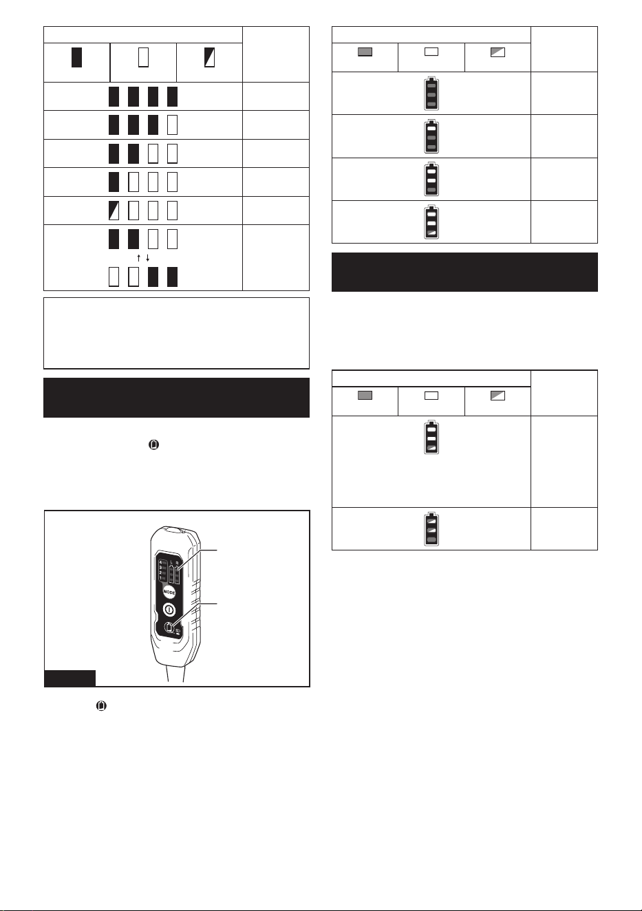
Indicating the remaining battery
capacity
Press the check button on the battery cartridge to indi-
cate the remaining battery capacity. The indicator lamps
light up for a few seconds.
1
2
Fig.2
► 1. Indicator lamps 2. Check button
7 ENGLISH
Indicator lamps Remaining
capacity
Lighted O Blinking
75% to 100%
50% to 75%
25% to 50%
0% to 25%
Charge the
battery.
The battery
may have
malfunctioned.
NOTE: Depending on the conditions of use and the
ambient temperature, the indication may dier slightly
from the actual capacity.
NOTE: The rst (far left) indicator lamp will blink when
the battery protection system works.
Indicating the remaining battery
capacity on the switch box
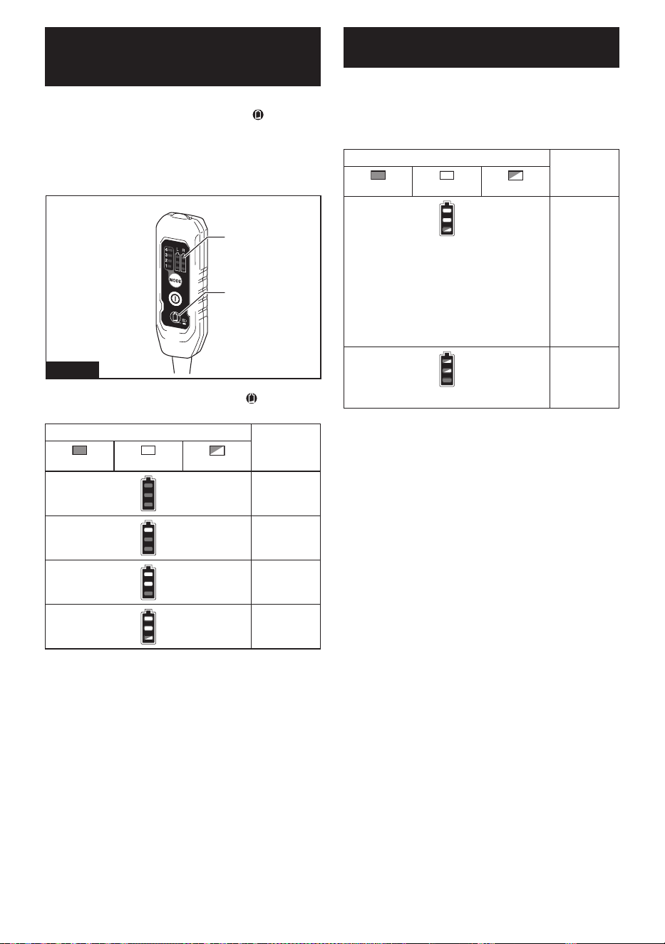
The remaining battery capacity can be checked on the
switch box. Press the button to indicate the remain-
ing battery capacities.
"L" and "R" on the switch box correspond to the left and
right battery cartridges, respectively. Follow the indica-
tion when you replace the battery cartridge.
1
2
Fig.3
► 1. Battery indicator 2. Battery check / LED light
button
Battery indicator status Remaining
battery
capacity
On
O
Blinking
50% to 100%
20% to 50%
0% to 20%
Charge the
battery
Appliance / battery protection
system
The appliance is equipped with appliance / battery
protection system. This system automatically cuts o
power to the motor to extend appliance and battery
life. In this situation, the battery indicator lights up as
following table.
Battery indicator status Status
On
O
Blinking
Overload
protection
(battery) /
Overheat
protection
(battery) /
Overdischarge
protection
Overheat
protection
(appliance)
The appliance and the LED light will automatically stop
during operation if the appliance or battery is placed
under one of the following conditions:
Overload protection
When the appliance / battery is operated in a manner
that causes it to draw an abnormally high current, the
appliance automatically stops. In this situation, turn the
appliance o and stop the application that caused the
appliance to become overloaded. Then turn the appli-
ance on to restart.
Overheat protection
When the appliance / battery is overheated, the appli-
ance stops automatically. In this situation, let the appli-
ance / battery cool down before turning the appliance
on again.
Overdischarge protection
When the battery capacity becomes low, the appliance
stops automatically. If the product does not operate
even when the switches are operated, remove the bat-
teries from the appliance and charge the batteries.
8 ENGLISH
Protections against other causes
Protection system is also designed for other causes that
could damage the appliance and allows the appliance to
stop automatically. Take all the following steps to clear
the causes, when the appliance has been brought to a
temporary halt or stop in operation.
1. Turn the appliance o, and then turn it on again to
restart.
2. Charge the battery(ies) or replace it/them with
recharged battery(ies).
3. Let the appliance and battery(ies) cool down.
If no improvement can be found by restoring protection
system, then contact your local Makita Service Center.
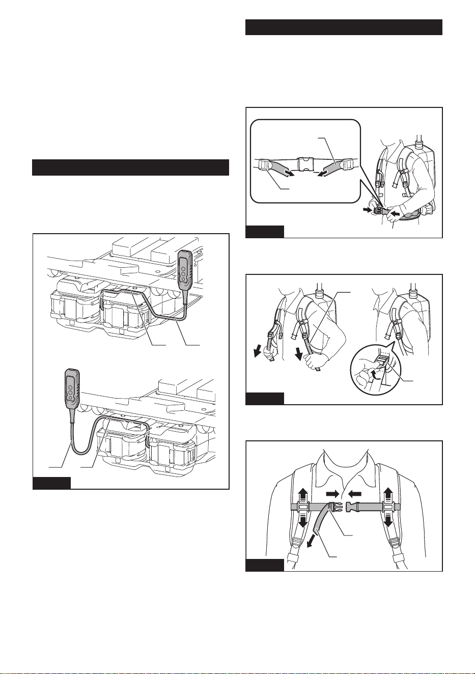
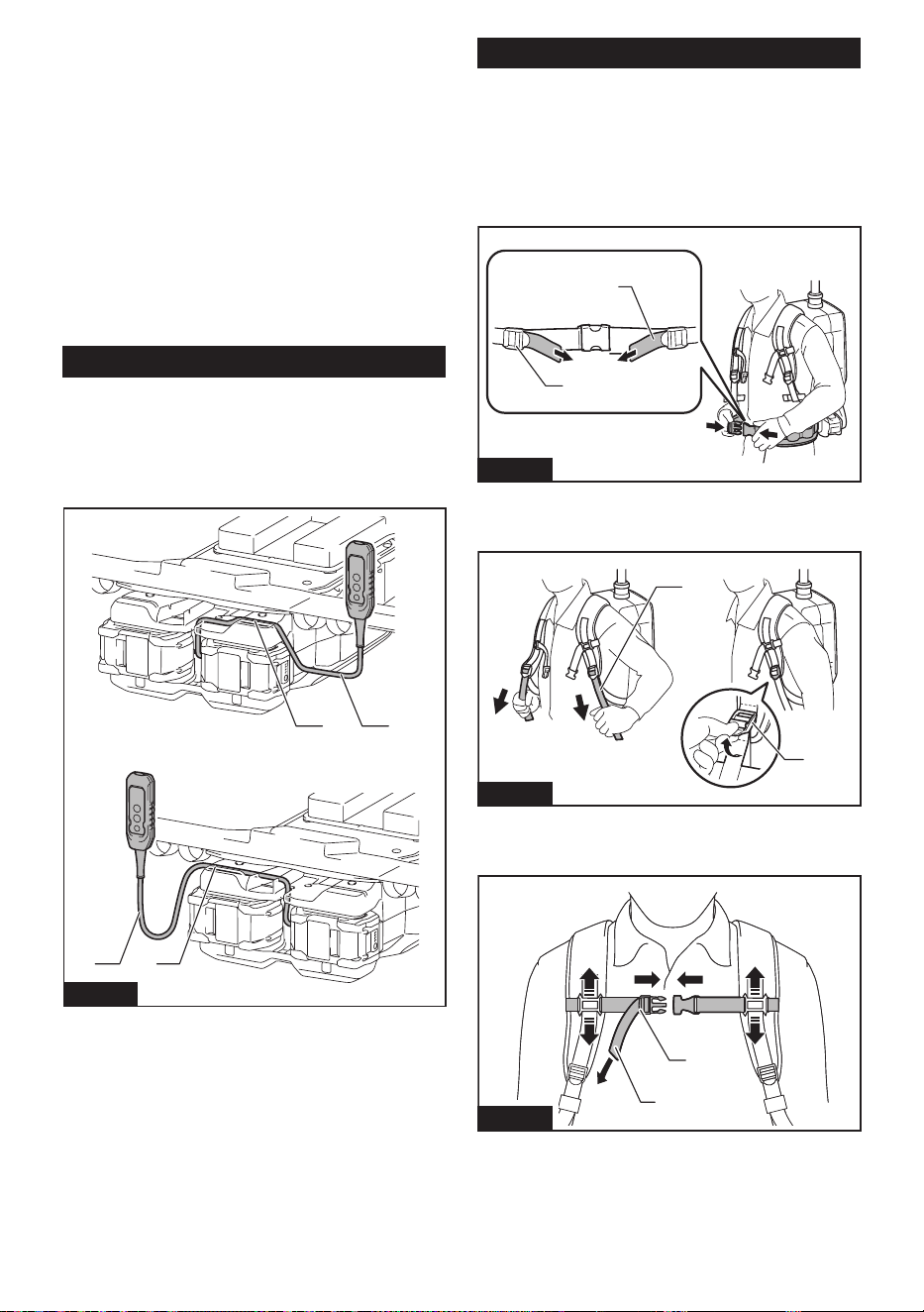
Switch box position
The switch box can be hooked on either side of the
lower belt. Arrange the cord so that the switch box
comes to your desired side. To prevent the cord from
being damaged, pass the cord through the groove as
illustrated.
1
1
2
2
Fig.4
► 1. Groove 2. Cord
Adjusting belts
The tightness of the shoulder belts, upper and lower
belts can be adjusted. Put your arms through the shoul-
der belts rst then fasten the lower and upper belts.
To tighten, pull the end of the strap as illustrated. To
loosen, pull up the end of the fastener.
Lower belt
1
2
Fig.5
► 1. Strap 2. Fastener
Shoulder belts
1
2
Fig.6
► 1. Strap 2. Fastener
Upper belt
2
1
Fig.7
► 1. Strap 2. Fastener
9 ENGLISH
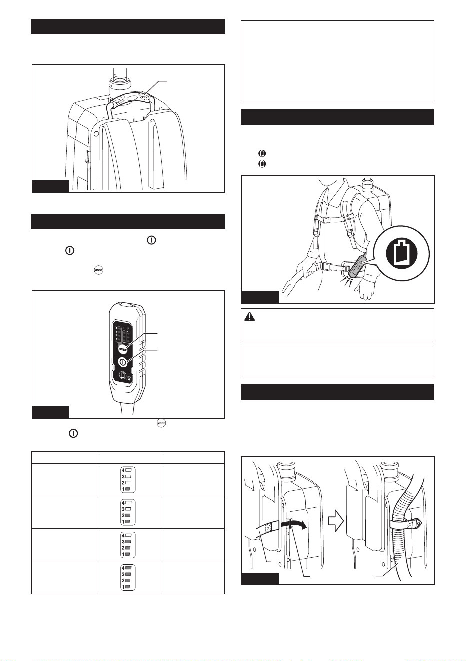
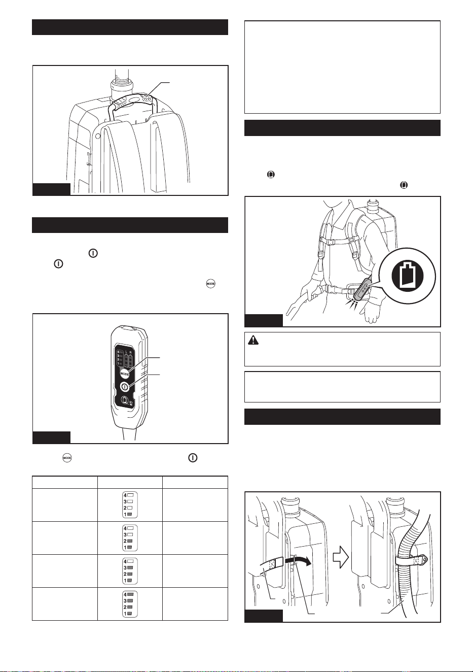
Carrying hook
Always grab the carrying hook when handling the vac-
uum cleaner body.
1
Fig.8
► 1. Carrying hook
Switch action
To start the cleaner, simply press button. To switch
o, press button again.
You can change the suction power of the cleaner in four
steps by pressing button. Each press on this button
repeats the 1 to 4 mode in a cycle.
1
2
Fig.9
► 1. Suction power change button
2. ON/OFF
button
Level Indication Mode
1
Quiet mode
2
Normal speed
mode
3
High speed mode
4
Max speed mode
NOTE: You can change the suction power before
turning on the cleaner.
NOTE: The cleaner starts the operation with the
same suction power as the last operation.
NOTE: If you remove the battery immediately after
turning o the appliance, while the motor is rotating,
the cleaner may not start the operation with the same
suction power as the last operation.
LED light
LED light is installed in the head of the switch box
to ease the operations in dark places. Press and
hold button to turn the light on. To turn o, press and
hold button again.
Fig.10
CAUTION: Do not look in the light or see the
source of light directly. Never aim the light to
other people's eyes.
NOTE: The LED light is automatically turned o when
the vacuum cleaner is not operated for more than 10
minutes.
Hose band
Hose band can be used for holding the hose or exible
rubber nozzle.
To secure the hose to the vacuum cleaner body, pass
the hose band through the slot on the body. You can
attach the hose band on either side.
1
2
3
Fig.11
► 1. Hose band 2. Slot 3. Hose
10 ENGLISH
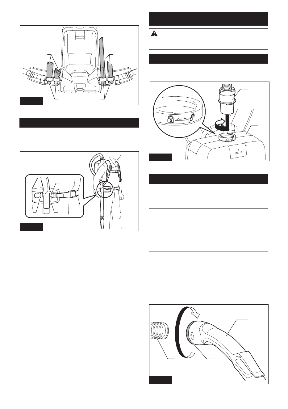
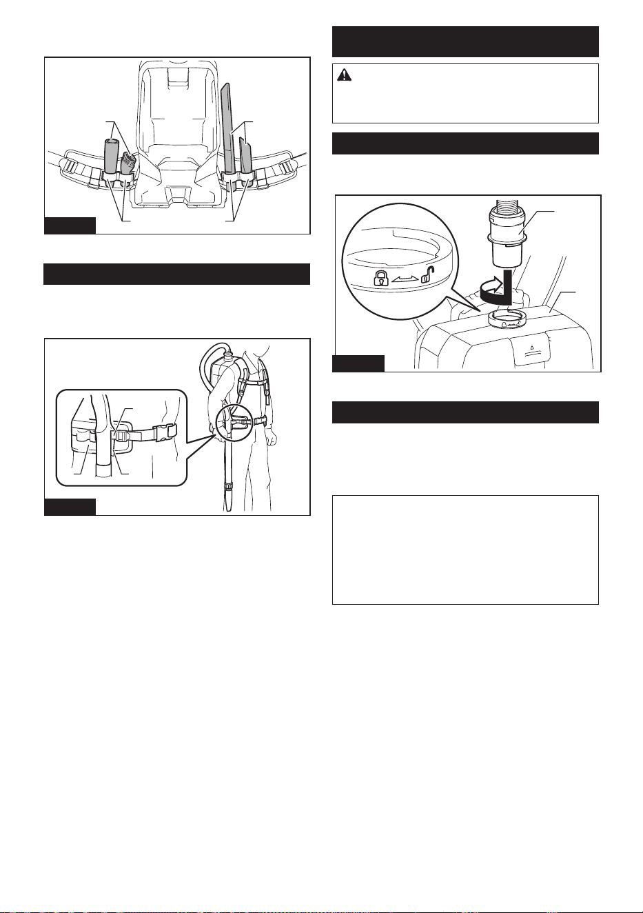
The loops on the lower belt can be used for carrying
nozzles as illustrated.
11
22
Fig.12
► 1. Loop 2. Nozzle
Hose hook
When you suspend the operation, the hook on the bent
pipe assembly can be used for hanging the wand on the
hanging part of the lower belt.
2
3
1
Fig.13
► 1. Hook 2. Lower belt 3. Hanging part
ASSEMBLY
CAUTION:
Always be sure that the appliance
is switched o and the battery cartridge is removed
before carrying out any work on the appliance.
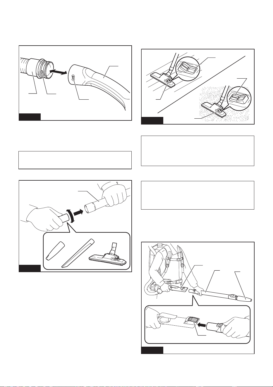
Assembling hose
Insert the hose cu into the vacuum cleaner body and
turn it clockwise.
Fig.13
1
2
Fig.14
► 1. Hose cu 2. Vacuum cleaner body
Using as a cleaner
Attaching bent pipe assembly
Optional accessory
NOTE: You don't need to perform this procedure
if your model comes with the bent pipe assembly
attached to the hose.
NOTE:
There are two types of bent pipe assembly; the
one for slide-type extension wand and the one for ring-
type extension wand. If you prepare the bent pipe assem-
bly, choose the one for your desired extension wand type.
The bent pipe assembly is used for connecting the exten-
sion wand or nozzle for vacuum cleaning to this product.
If you want to use this product as the vacuum cleaner,
attach the bent pipe assembly to the hose.
For the screw-in type bent pipe assembly
To attach, unscrew the front cu from the hose and
fasten the sleeve of bent pipe assembly onto the hose.
To remove, loosen the sleeve of bent pipe assembly from the hose.
1
2
3
Fig.15
► 1. Hose 2. Bent pipe assembly 3. Sleeve
11 ENGLISH
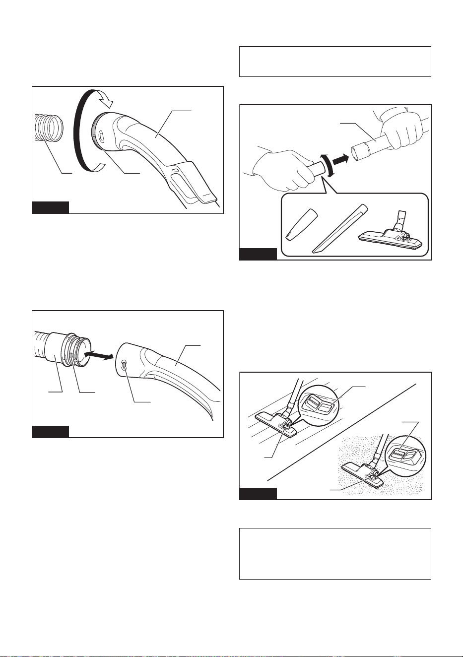
For the snap-on type bent pipe assembly
To attach, insert the hose end into the bent pipe assem-
bly. Make sure that the tabs on the hose end snap into
the holes on the bent pipe assembly.
To remove, pull the bent pipe assembly while pressing
both of the tabs on the hose end.
4
1
3
2
Fig.16
► 1. Hose end 2. Tab 3. Hole 4. Bent pipe assembly
Assembling nozzle and wand
Optional accessory
NOTE: The type of the nozzle and wand included in
the product varies depending on countries. In some
countries, the nozzle and wand are not included.
1. Twist and insert the nozzle to the extension wand.
1
23 4
Fig.17
► 1. Extension wand 2. Flexible rubber nozzle
3. Corner nozzle 4. Floor/carpet switching t-nozzle
When using oor/carpet switching t-nozzle, you can
change the mode depending on the place.
— Floor mode: suitable for a smooth place such as a
hard oor
— Carpet mode: suitable for a shaggy place such as
a carpet or a rug
1
1
2
3
Fig.18
►
1. Mode switching button 2. Floor mode 3. Carpet mode
NOTE: By twisting the nozzle while inserting, the noz-
zle can be attached to the extension wand securely.
NOTE: For the model with ø38 mm hose and front
cu 38, attach the supplied nozzle to the aluminum
bent pipe / aluminum straight pipe.
2. Follow the procedures below, depending on the
type of the extension wand:
NOTE: The slide-type extension wand and the ring-
type extension wand are not compatible with each
other. If you want to change the slide-type extension
wand to the ring-type extension wand or vice versa,
change the bent pipe assembly also.
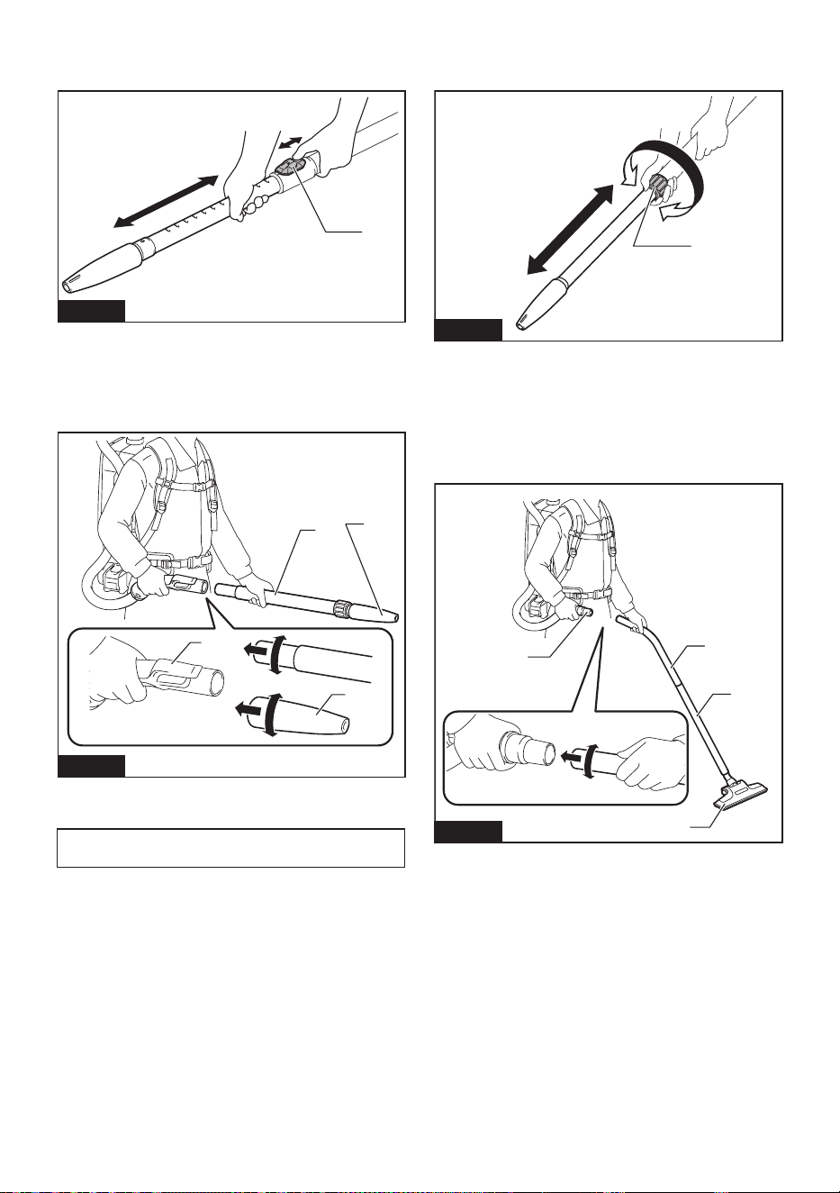
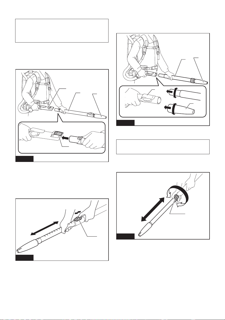
For the slide-type extension wand
Shoulder the vacuum cleaner body then insert the
extension wand into the bent pipe assembly until it
clicks. To disconnect, extract the extension wand with
pressing the button.
1
2
3
4
Fig.19
► 1. Bent pipe assembly 2. Button 3. Slide-type exten-
sion wand 4. Flexible rubber nozzle
12 ENGLISH
The length of the wand can be adjusted.
With pressing the slide button, adjust the wand length.
The length is locked when releasing the slide button.
1
Fig.20
► 1. Slide button
For the ring-type extension wand
Shoulder the vacuum cleaner body then twist and insert
the extension wand into the bent pipe assembly. To
disconnect, twist and extract it.
1
2
3
3
Fig.21
► 1. Bent pipe assembly 2. Ring-type extension wand
3. Flexible rubber nozzle
NOTE: The exible rubber nozzle can be attached to
the bent pipe assembly without pipe lock directly.
The length of the wand can be adjusted.
Loosen the ring on the wand and adjust the wand
length. Tighten the ring at your desired length.
1
Fig.22
► 1. Ring
For the aluminum bent pipe / aluminum straight
pipe
(Only for the model with ø38 mm hose and front cu 38)
Shoulder the vacuum cleaner body then twist and insert
the pipe into the front cu. To disconnect, twist and
extract it.
1
3
2
4
Fig.23
► 1. Front cu 38 2. Aluminum bent pipe 3. Aluminum
straight pipe 4. Nozzle
13 ENGLISH
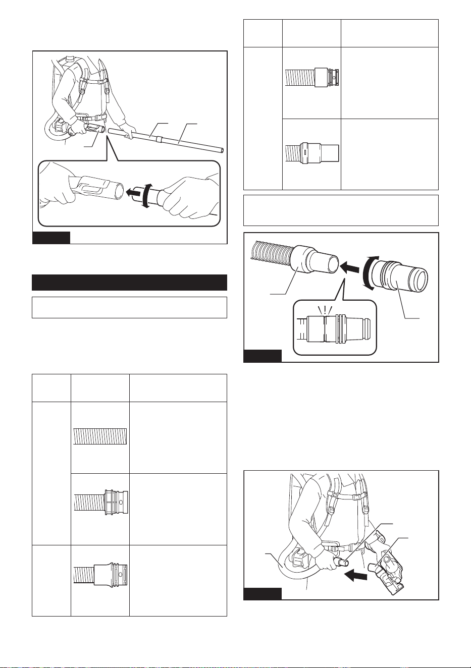
For the two aluminum straight pipes
Shoulder the vacuum cleaner body then twist and insert
the pipes. To disconnect, twist and extract it.
3
1
2
Fig.24
► 1. Bent pipe assembly 2. Aluminum straight pipe 1
3. Aluminum straight pipe 2
Connecting the tool
NOTE: If the bent pipe assembly is attached to the
hose, remove it beforehand.
To connect a tool to the cleaner, the dedicated hose
and/or additional parts are required. Depending on your
cleaner model, you need to replace the hose and/or
prepare additional parts.
Refer to the following table for details.
Supplied
hose
diameter
Hose end type Action
ø28 mm
without part
Attach the front cu.
with snap-on part
Replace the hose end
(snap-on part) with the front
cu.
The hose end can be removed
by turning it counterclockwise.
ø32 mm
with snap-on part
Replace the hose with the one
for dust extraction (ø28 mm,
with front cu).
Supplied
hose
diameter
Hose end type Action
ø38 mm
with snap-on part
Replace the hose with the one
for dust extraction (ø28 mm,
with front cu).
with front cu 38
Attach the joint 22-38 or the
front cu 24.
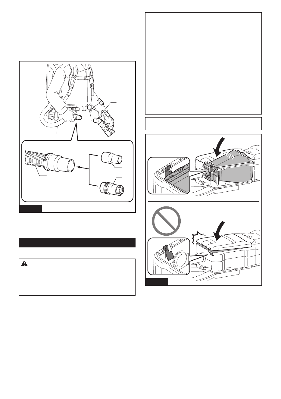
NOTE: Always use a suitable front cu. When using
the front cu 24, attach it to the front cu 22 that is
connected to the hose.
1
2
Fig.25
► 1. Front cu 22 2. Front cu 24
When using ø28 mm dust extraction
hose
1. Attach the front cu to the hose for dust extraction.
When connecting the front cu, make sure that it is
securely screwed on the hose.
2. Connect the front cu to the tool's extraction
outlet.
1
2
3
Fig.26
► 1. Front cu 2. Extraction outlet 3. Hose
The front cu can be detached by turning it counter-
clockwise while holding the hose.
14 ENGLISH
When using ø38 mm hose with front
cu 38
1. Twist and insert the joint or the front cu to the
inlet part on the hose, depending on the tool that you
are going to connect.
2. Connect the front cu to the tool's extraction
outlet.
1
2
3
4
Fig.27
► 1. Joint 2. Front cu 3. Extraction outlet 4. Hose
To remove the joint and the front cu, follow the installa-
tion procedures in reverse.
Installing lter bag / dust bag
Optional accessory
CAUTION: Do not use a damaged lter bag.
Always use the vacuum cleaner with the lter bag
properly installed. Otherwise the vacuumed dust
or particles may be exhausted from the cleaner
and they may cause respiratory disease to the
operator.
Install either dust bag or lter bag before using cleaner.
— Dust bag is usable many times repeatedly by
cleaning it out.
— Filter bag is a throw-away type. Throw away the
entire lter bag without emptying when it has
become full.
NOTICE: When the lter bag is already full,
replace with new one. When the dust bag is
already full, empty it. Continuous use with the lter
bag/dust bag full results in reduced suction power.
NOTICE: To prevent dust from getting into the
motor:
— Make sure that the lter bag/dust bag is
installed before use.
— Do not use a broken or ripped bag.
Otherwise the motor may be broken.
NOTICE: Do not fold the cardboard at its open-
ing when installing the lter bag/dust bag.
NOTICE: The lter bag/dust bag for the cleaner
is an important component for maintaining the
appliance performance. Using non-genuine lter
bag/dust bag may cause smoke or ignition.
NOTE: When the lter bag/dust bag is not installed in
the cleaner, the front cover does not close completely.
Fig.28
15 ENGLISH
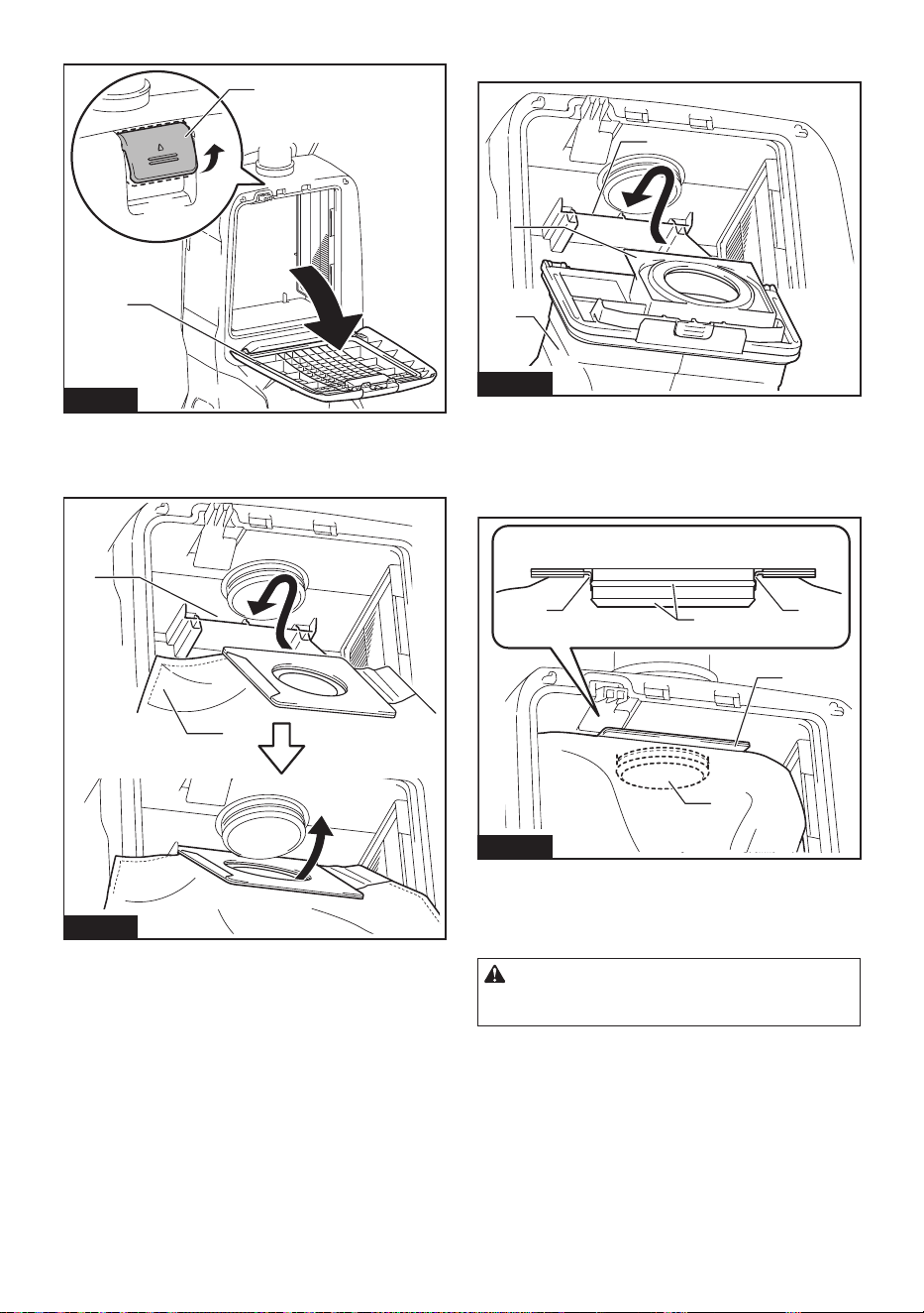
1. Unlock the lever and open the front cover.
2
1
Fig.29
► 1. Lever 2. Front cover
2. Insert the lter bag into the slit on the upper side of
the room as illustrated.
1
2
Fig.30
► 1. Slit 2. Filter bag
When using the dust bag, insert the brim of the dust bag
into the slit.
2
3
1
Fig.31
► 1. Slit 2. Brim 3. Dust bag
3. Align the hole of the lter bag with the hose cu
and push the cardboard portion to the end. Make sure
that the rubber ring on the lter bag goes over the rim
on the hose cu.
11
2
3
4
Fig.32
► 1. Rubber ring on the lter bag 2. Rim on the hose
cu 3. Cardboard portion of the lter bag 4. Hose
cu
4. Lock the front cover certainly.
CAUTION: Be careful not to pinch your n-
gers when hooking the latch, and when closing
the front cover.
16 ENGLISH
Harness cover
Optional accessory
When using the harness cover, follow the procedure
below to attach it.
NOTE: When installing the harness cover, do not
mistake the front and back of the harness cover.
NOTE: The harness cover is washable. Follow the
washing instructions on the tag.
Fig.33
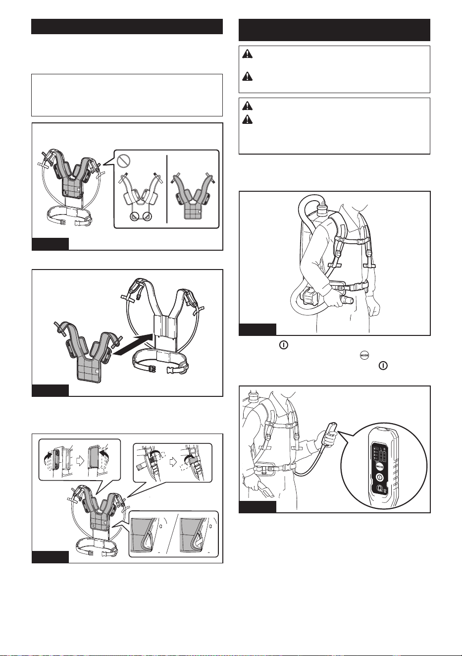
1. Spread the harness cover on the harness.
Fig.34
2. Secure the harness shoulder straps with the hook
and loop fasteners of the harness cover. Hook the band
of the harness cover on the harness.
Fig.35
OPERATION
WARNING: Operators shall be adequately
instructed on the use of the vacuum cleaner.
WARNING: This vacuum cleaner is not suit-
able for picking up hazardous dust.
CAUTION: This cleaner is for dry use only.
CAUTION: During operation, be conscious
of the vacuum cleaner on your back. You may
lose your balance if the vacuum cleaner body bumps
against a wall or the hose is hooked by an obstacle.
1. Shoulder the vacuum cleaner body and fas-
ten upper and lower belts. Adjust the tightness as
necessary.
Fig.36
2. Press
button to start vacuuming. If you want
to change the suction power, press button until the
desired suction power is selected. Press button to
stop.
Fig.37
17 ENGLISH
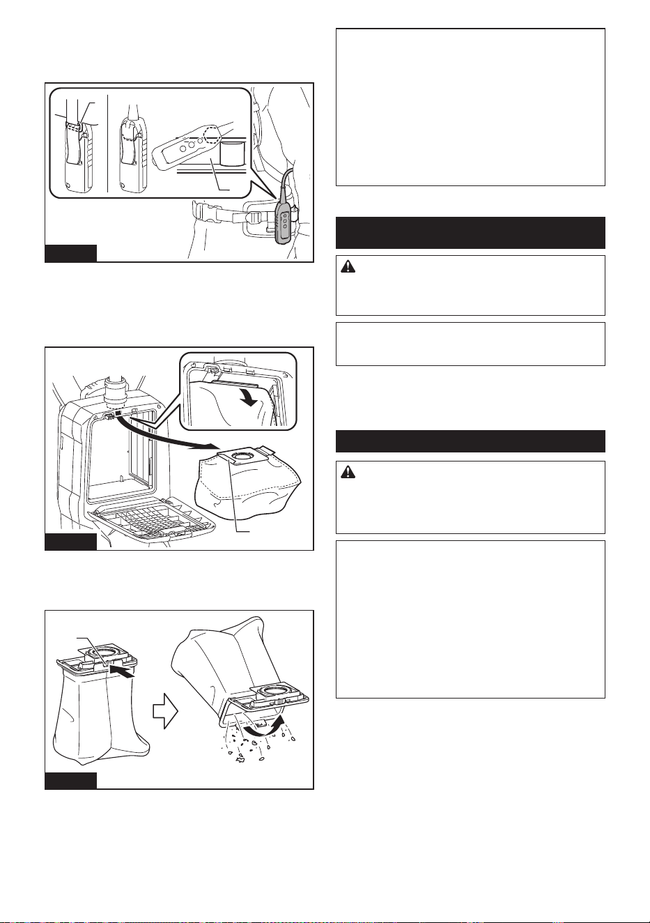
During the operation, hook the switch box on the D-ring
or the hanging part of the lower belt. The hook can be
slanted for lighting forward when hooked on the hang-
ing part.
1
2
Fig.38
► 1. D-ring 2. Hanging part
3. Replace the lter bag when it becomes full. Open
the front cover and take out the lter bag. Pull the strip
on the side of the opening to shut the lter bag and
dispose of the lter bag in whole.
1
Fig.39
► 1. Strip
When using a dust bag, take out the dust bag and dis-
pose of the dust by releasing the latch.
1
Fig.40
► 1. Latch
NOTICE: Do not put lter bag/dust bag or other
heavy objects on the front cover. The appliance
may fall down.
NOTICE: Periodically check the lter bag
whether the lter is full or not. Continuous use with
the lter bag full results in reduced suction power.
NOTICE: Do not use a used lter bag. The lter
bag is designed for single use. Using lter bag repeat-
edly may cause clogging of the lter and results in
damage to the cleaner. If you want to use the bag
repeatedly, use a dust bag.
MAINTENANCE
CAUTION: Always be sure that the appli-
ance is switched o and the battery cartridge is
removed before attempting to perform inspection
or maintenance.
NOTICE: Never use gasoline, benzine, thinner,
alcohol or the like. Discoloration, deformation or
cracks may result.
To maintain product SAFETY and RELIABILITY,
repairs, any other maintenance or adjustment should
be performed by Makita Authorized or Factory Service
Centers, always using Makita replacement parts.
Cleaning the HEPA lter
CAUTION: Do not use the vacuum cleaner
without a lter or continue to use dirty or dam-
aged lter. Vacuumed dust or particles may be
exhausted from the cleaner and they may cause
respiratory disease to the operator.
NOTICE: To keep optimum suction power and
clean exhaust, clean the lter periodically. If
enough suction power is not obtained even after
the cleaning, replace the lter with new one.
NOTICE: To prevent the lter from being dam-
aged, do not use following tools and similar items
for cleaning:
— Air duster
— High pressure washer
— Tools made of hard materials such as a wire
brush
18 ENGLISH
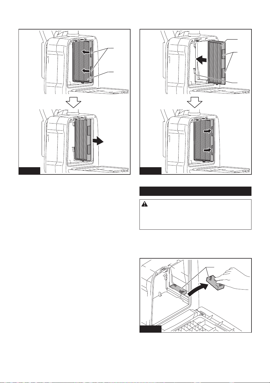
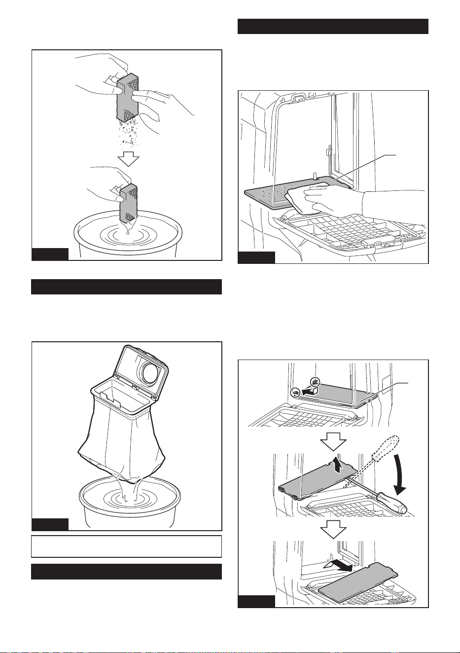
1. Open the front cover and take out the lter bag/
dust bag. Release the hook on the lter and remove it
from the vacuum cleaner body.
1
2
Fig.41
► 1. Hook 2. HEPA lter
2. Beat the dust o from the lter. The lter can be
washed with water. Rinse away the dust and particles
on the lter every 1 or 2 month. After that, dry the lter
completely in a shaded and well-ventilated place to
prevent unpleasant odor or malfunctions.
3. To install the lter, insert the side without the
hooks into the groove then push in the lter until the
hooks are secured with a click.
1
2
3
Fig.42
► 1. Groove 2. HEPA lter 3. Hook
Cleaning the sponge lter
CAUTION: After cleaning the sponge lters,
be sure to install them to the vacuum cleaner.
If washed in water, dry them up thoroughly before
installing. Insuciently dried sponge lters may
shorten the service life of the motor.
Sponge lters underneath the HEPA lter prevent dust
from getting into the motor.
1. Remove the sponge lters from the vacuum
cleaner.
1
Fig.43
► 1. Sponge lter
19 ENGLISH
2. Wipe and shake dust o the sponge lters by
hand. When the sponge lters are clogged, wash them
in soapy water.
Fig.44
3. Install the sponge lters in their original position.
Cleaning the dust bag
Regularly clean the dust bag with soap and water. Turn
the dust bag inside out and remove the sticky dust.
Wash lightly by hand and rinse well with water. Dry
completely before installing to the vacuum cleaner.
Fig.45
NOTICE: Wet dust bag lowers the vacuuming per-
formance as well as the life of the motor.
Cleaning the clog
When cleaning the clog, remove the hose or the exten-
sion wand, or the bent pipe assembly to check inside.
Refer to the section for attaching bent pipe assembly.
Cleaning the room for lter bag/dust bag
This appliance is equipped with a dust beating system. As you
walk while carrying the cleaner, springs underneath the board
vibrate the board and shake the dust o the lter bag/dust bag.
When cleaning the room for lter bag/dust bag, remove
and wipe the board inside.
1
Fig.46
► 1. Board
Removing the board
1. Remove the HEPA lter. Refer to the section for
cleaning the HEPA lter for how to remove.
2. Push down the board, and slide it to left until the
board touches the wall.
3. Lift the right side of the board up and take it out.
1
Fig.47
► 1. Board
20 ENGLISH
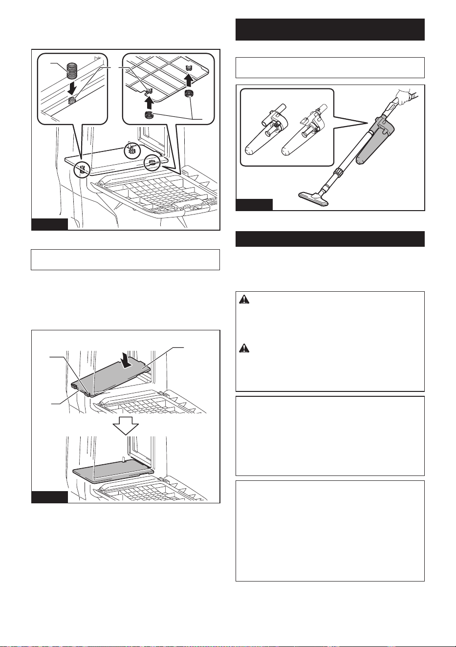
The board is supported by three springs.
If the springs came o from the projections, reattach
them as illustrated.
2
3
1
Fig.48
► 1. Long spring 2. Short spring 3. Projection
NOTE: Attach the springs securely so that the springs
touch the root of the projections.
Attaching the board
1. Insert the straight side of the board into the
catches in the lower left side of the room.
2. Put the right side of the board in place.
2
1
3
Fig.49
► 1. Board 2. Straight side 3. Catch
CYCLONE ATTACHMENT
Optional accessory
NOTE: When using the cyclone attachment with this
appliance, the bent pipe is also required.
1
Fig.50
► 1. Cyclone attachment
About the cyclone attachment
Using the cleaner with the cyclone attachment installed
reduces the amount of dust that enters the dust bag,
which helps to prevent the suction force from weaken-
ing. In addition, cleaning after use is also simple.
CAUTION: Always be sure that the tool is
switched o and the battery cartridge is removed
before carrying out any work on the tool. If the
battery cartridge is left inserted, the cleaner may start
unexpectedly and result in injury.
CAUTION: Clean the mesh lter of the
cyclone attachment and the dust bag of the
cleaner unit when they become clogged.
Continued use in the clogged condition may result in
heating or smoke.
NOTICE: When the cyclone attachment is
attached, do not use the cyclone attachment in
the horizontal or upward facing condition. Doing
so may cause the mesh lter to become clogged.
NOTICE: Always use the cleaner with the dust
bag installed, even when using the cyclone
attachment. Using the cleaner without the dust bag
installed may result in a motor malfunction.
NOTE: Check that the cyclone attachment, cleaner,
and straight pipe are locked properly before use.
NOTE: Empty the dust case of the cyclone attach-
ment and the dust bag of the cleaner when dust has
accumulated. Continued use will result in weakened
suction force.
NOTE: You can use the cyclone attachment with or
without lock function.
NOTE: To install or remove the cyclone attachment,
refer to the section "Using as a cleaner".
21 ENGLISH
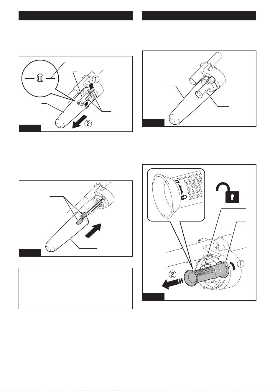
Disposing of dust
When dust has accumulated up to the full line of the
dust case, follow the procedure below and dispose of
the dust.
1. Hold the dust case rmly, press and hold the two
buttons, and remove the dust case.
2
3
1
4
Fig.51
► 1. Full line 2. Dust case 3. Button (two locations)
4. Mesh lter
2. Dispose of the dust inside the dust case and
remove any dust and powder adhered to the surface of
the mesh lter.
3. Insert the dust case all the way until the two but-
tons lock with a click.
2
1
Fig.52
► 1. Dust case 2. Button (two locations)
NOTE: Check that the cyclone attachment, cleaner,
and straight pipe are locked properly before restarting
operation.
NOTE: If the suction force does not recover even
after disposing of the dust and cleaning the mesh
lter, check whether dust has accumulated in the dust
bag of the cleaner or clogging has occurred.
Cleaning
When the dust case becomes dirty or the mesh lter is
clogged, remove and wash them with water. (Refer to
“Disposing of dust” for the removal procedure.)
Dry the parts thoroughly before reinstallation and use.
1
2
Fig.53
► 1. Dust case 2. Mesh lter
When the mesh lter gets dirty badly, clean it in the
following procedures.
1. Turn the mesh lter counterclockwise and remove
it while the hooks are unlocked.
1
2
Fig.54
► 1. Mesh lter 2. Hook
2. Remove the dust on the mesh lter and then wash
it with water. After that, dry it thoroughly.
22 ENGLISH
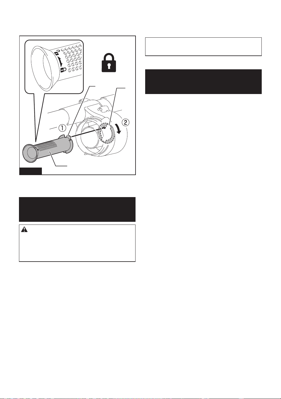
3. Insert the mesh lter into the base while the hooks
are aligned with the ports. Turn the mesh lter clockwise
until the hooks are locked with a click. Make sure that
the mesh lter is installed securely.
2
1
3
Fig.55
► 1. Mesh lter 2. Hook 3. Port
OPTIONAL
ACCESSORIES
CAUTION: These accessories or attachments
are recommended for use with your Makita prod-
uct specied in this manual. The use of any other
accessories or attachments might present a risk of
injury to persons. Only use accessory or attachment
for its stated purpose.
Some accessories may not be installed according to the
combination of parts.
If you need any assistance for more details regard-
ing these accessories, ask your local Makita Service
Center.
• Hose (for vacuum cleaner type)
• Hose (for dust extraction type)
• Extension wand
• Flexible rubber nozzle
• T-shape nozzle
• Seat nozzle
• Corner nozzle
• Shelf brush
• Round brush
• Bent pipe assembly
• Filter bag
• Dust bag
• Front cu
• HEPA lter
• Pipe
• Harness cover
• Cyclone attachment
• Makita genuine battery and charger
NOTE: Some items in the list may be included in the
tool package as standard accessories. They may
dier from country to country.
MAKITA LIMITED
WARRANTY
Please refer to the annexed warranty sheet for the
most current warranty terms applicable to this product.
If annexed warranty sheet is not available, refer to the
warranty details set forth at below website for your
respective country.
United States of America: www.makitatools.com
Canada: www.makita.ca
Other countries: www.makita.com

23 ESPAÑOL
ESPAÑOL (Instrucciones originales)
ESPECIFICACIONES
Modelo: GCV08
Capacidad Bolsa del ltro 6,0 L (1,6 gal.)
Bolsa recolectora de polvo 5,5 L (1,5 gal.)
Volumen de aire máximo
(Con manguera diámetro ø32 mm (1-1/4″) x 1,0 m (39-3/8″))
2,4 m
3
/min (84,8 cu.ft/min)
Aspiradora 20 kPa
Dimensiones (La x An x Al)
(sin incluir el arnés, con BL4050F)
336 mm x 185 mm x 543 mm
(13-1/4″ x 7-1/4″ x 21-3/8″)
Tensión nominal 36 V - 40 V c.c. máx.
Peso neto 6,4 kg - 9,5 kg (14,1 lbs - 20,9 lbs)
• Debido a nuestro continuo programa de investigación y desarrollo, las especicaciones aquí incluidas están
sujetas a cambio sin previo aviso.
• Las especicaciones pueden variar de país a país.
• El peso incluye el o los cartuchos de batería, pero no los accesorios. La combinación de menor y mayor peso
del aparato y del o los cartuchos de batería se muestra en la tabla.
• La longitud de la manguera suministrada varía en función del país.
Cartucho de batería y cargador aplicables
Cartucho de batería BL4020 / BL4025 / BL4040 / BL4040F / BL4050F / BL4080F
Cargador DC40RA / DC40RB / DC40RC
• Algunos de los cartuchos de batería y cargadores enumerados arriba podrían no estar disponibles depen-
diendo de su área de residencia.
ADVERTENCIA: Use únicamente los cartuchos de batería y los cargadores indicados arriba. El uso de
cualquier otro cartucho de batería y cargador podría ocasionar una lesión y/o un incendio.
ADVERTENCIA: No use ningún alimentador con cableado eléctrico, como un adaptador para batería
o una unidad portátil de alimentación eléctrica, con este aparato. El cable de dicho alimentador podría impe-
dir la operación y ocasionar una lesión personal.
ADVERTENCIAS DE
SEGURIDAD
INSTRUCCIONES
IMPORTANTES DE
SEGURIDAD
Al usar cualquier aparato eléctrico,
siempre deben seguirse las precaucio-
nes básicas, incluyendo las siguientes:
GUARDE ESTAS
INSTRUCCIONES.
ADVERTENCIA
Para reducir el riesgo de incendio, des-
carga eléctrica o lesión:
1. No deje el aparato con la batería
puesta. Retire la batería del aparato
cuando no lo vaya a utilizar y antes
de dar servicio de mantenimiento.
2. No lo utilice sobre supercies
húmedas. No lo exponga a la lluvia.
Almacénelo en interiores.
3. No permita que sea utilizado como
un juguete. Supervise de cerca
cuando lo utilice cerca de niños.
4.
Utilícelo solamente como se describe
en este manual. Sólo use aditamentos
recomendados por el fabricante.

24 ESPAÑOL
5.
No lo utilice con una batería dañada.
Si el aparato no está funcionando
como debiera, se ha dejado caer, se
ha dañado, se ha dejado a la intem-
perie o ha caído sobre agua, llévelo
a un centro de servicio.
6. No manipule el aparato con las
manos mojadas.
7. No introduzca ningún objeto en las
aberturas. No lo utilice con ninguna
abertura bloqueada; manténgalo
libre de polvo, pelusa, cabello y
cualquier objeto que pueda reducir
el ujo de aire.
8. Mantenga el cabello, la ropa hol-
gada, los dedos y todas las partes
del cuerpo lejos de las aberturas y
piezas móviles.
9. Apague todos los controles antes
de retirar el cartucho de batería.
10. Tenga especial cuidado cuando lim-
pie en escaleras.
11. No lo utilice para recoger líquidos
inamables o combustibles, tal
como gasolina, ni en áreas donde
puedan estar presentes.
12. No recoja nada que se esté que-
mando o desprenda humo, tal
como cigarros, fósforos o cenizas
calientes.
13. No lo utilice sin la bolsa recolectora
de polvo colocada en su lugar.
GUARDE ESTAS
INSTRUCCIONES.
Este aparato está diseñado para uso
comercial.
Uso y cuidado de la herramienta
a batería
1. Evite un arranque accidental.
Asegúrese de que el interruptor
esté en la posición apagada antes
de conectar el paquete de bate-
rías, levantar el aparato o cargarlo.
Cargar el aparato con su dedo en el
interruptor o pasar energía al aparato
con el interruptor encendido puede
propiciar accidentes.
2. Desconecte el paquete de baterías
del aparato antes de hacer cual-
quier ajuste, cambiar accesorios o
almacenar el aparato. Estas medidas
de seguridad preventivas reducen el
riesgo de poner en marcha el aparato
accidentalmente.
3. Recargue sólo con el cargador
especicado por el fabricante. Un
cargador que es adecuado para un
solo tipo de batería puede generar
riesgo de incendio al ser utilizado con
otra batería.
4. Use los aparatos únicamente con
los paquetes de baterías designa-
dos especícamente para ellos. El
uso de otros paquetes de baterías
puede generar riesgo de lesiones e
incendio.
5. Cuando no se esté usando la bate-
ría, manténgala alejada de otros
objetos metálicos, como sujeta-
papeles (clips), monedas, llaves,
clavos, tornillos u otros objetos
pequeños de metal los cuales pue-
den actuar creando una conexión
entre las terminales de la batería.
Originar un cortocircuito en las termi-
nales puede causar quemaduras o
incendios.
6. En condiciones abusivas, podrá
escapar líquido de la batería; evite
tocarlo. Si lo toca accidentalmente,
enjuague con agua. Si hay contacto
del líquido con los ojos, busque
asistencia médica. Puede que el
líquido expulsado de la batería cause
irritación o quemaduras.
7. No utilice un paquete de baterías
o aparato que esté dañado o haya
sido modicado. Las baterías daña-
das o modicadas podrían com-
portarse de manera impredecible
causando un incendio, explosión o
riesgo de lesión.
8. No exponga un paquete de baterías
o aparato al fuego o a una tempe-
ratura excesiva. La exposición al
fuego o una temperatura superior a
130 °C podría causar una explosión.

25 ESPAÑOL
9.
Siga todas las instrucciones rela-
tivas a la carga y no cargue el
paquete de baterías o el aparato
fuera del rango de temperatura
especicado en las instrucciones.
Cargar de manera inapropiada o a
temperaturas fuera del rango especi-
cado podría dañar la batería e incre-
mentar el riesgo de incendio.
10.
Pida que el servicio lo realice un técnico
en reparaciones calicado y que utilice
únicamente piezas de repuesto idénti-
cas a las originales. Esto garantizará que
se mantenga la seguridad del producto.
11. No modique ni intente reparar el
aparato ni el paquete de baterías
salvo como se indique en las ins-
trucciones para el uso y cuidado.
REGLAS DE
SEGURIDAD
ADICIONALES
1. Lea cuidadosamente este manual
de instrucciones y el manual de
instrucciones del cargador antes de
usar el aparato.
2. No aspire los siguientes elementos:
• Líquidos inamables (quero-
seno, gasolina, disolventes
como bencina, diluyentes, etc.)
• Sustancias calientes que están
ardiendo o echando humo
(cigarrillos, cerillas, palitos de
incienso, velas, cenizas calien-
tes), chispas y polvo metálico
generados por el corte o el
lijado de metales, etc.
• Materiales inamables (tóner,
pinturas, aerosoles, etc.)
• Espumas, como limpiadores de
alfombras, etc. (pueden causar
explosiones o incendios)
• Sustancias explosivas o pirofó-
ricas (nitroglicerina, aluminio,
magnesio, titanio, zinc, fósforo
rojo, fósforo amarillo, celu-
loide, etc., y su polvo, gases o
vapores)
• Objetos alados (cristal, cubier-
tos, astillas de madera, meta-
les, piedras, clavos, cuchillas,
tachuelas, etc.)
• Polvo no conductor y solidi-
cante (polvo metálico o de
carbono)
• Deshumidicador
• Grandes cantidades de polvo
(harina, polvo de extintor de
incendios, etc.)
• Sustancias que causan sínto-
mas tóxicos
• Productos químicos agresivos
(ácidos, alcalinos, etc.)
• Basura líquida o húmeda, inclu-
yendo vómitos y heces
• Asbesto
• Pesticidas
Tal acción podría ocasionar un
incendio, lesiones y/o daños
materiales.
Para reducir la exposición a estas
sustancias químicas, utilice un
equipo de protección respiratoria
aprobado, tal como las máscaras
contra polvo que están especial-
mente diseñadas para ltrar partí-
culas microscópicas. No apunte la
salida de aire a la cara y al cuerpo.
NOTA: Lea el reglamento OSHA en
lo referente a polvo de sílice a n de
entender los requisitos necesarios
para reducir la exposición al polvo
de sílice en el puesto de trabajo.
Contiene normas especícas sobre
el taladrado, la demolición, el corte
y el lijado de materiales que con-
tienen sílice. Todos los requisitos
de la OSHA relacionados con la
reducción de polvo de sílice se pue-
den encontrar en el sitio web de la
OSHA: www.osha.gov.
3. Detenga la operación de inmediato
si nota algo anormal.
4. Si deja caer o golpea la aspira-
dora, verique cuidadosamente
si hay grietas o daños antes de la
operación.
5. No la acerque a estufas ni a otras
fuentes de calor.

26 ESPAÑOL
6.
No obstruya el oricio de ujo de
entrada ni los oricios de ventilación.
7. Este aparato no se destina para
utilizarse por personas (incluyendo
niños) cuyas capacidades físicas,
sensoriales o mentales sean dife-
rentes o estén reducidas o carezcan
de experiencia o de conocimiento,
a menos que dichas personas reci-
ban una supervisión o capacitación
para el funcionamiento del aparato
por una persona responsable de su
seguridad.
8. Los niños deben supervisarse para
asegurar que ellos no empleen los
aparatos como juguete.
Símbolos
A continuación se muestran los símbolos utilizados
para la herramienta.
volts o voltios
corriente directa o continua
Instrucciones
importantes de
seguridad para
el cartucho de
batería
1. Antes de utilizar el cartucho de bate-
ría, lea todas las instrucciones e
indicaciones de precaución en el (1)
el cargador de batería, (2) la batería,
y (3) el producto con el que se utiliza
la batería.
2. No desarme ni modique el car-
tucho de batería. Podría ocurrir
un incendio, calor excesivo o una
explosión.
3. Si el tiempo de operación se ha
acortado en exceso, deje de ope-
rar de inmediato. Podría correrse
el riesgo de sobrecalentamiento,
posibles quemaduras e incluso
explosión.
4.
En caso de que ingresen electrolitos en
sus ojos, enjuáguelos bien con agua lim-
pia y consulte de inmediato a un médico.
Esto podría ocasionar pérdida de visión.
5.
Evite cortocircuitar el cartucho de batería:
(1) No toque las terminales con nin-
gún material conductor.
(2) Evite guardar el cartucho de
batería en un cajón junto con
otros objetos metálicos, tales
como clavos, monedas, etc.
(3) No exponga el cartucho de bate-
ría al agua o la lluvia.
Un cortocircuito en la batería puede
causar un ujo grande de corriente,
sobrecalentamiento, posibles quema-
duras e incluso una descompostura.
6. No guarde ni utilice la herramienta
y el cartucho de batería en lugares
donde la temperatura pueda alcan-
zar o exceder los 50 °C (122 °F).
7. Nunca incinere el cartucho de bate-
ría incluso en el caso de que esté
dañado seriamente o ya no sirva
en absoluto. El cartucho de batería
puede explotar si se tira al fuego.
8. No clave, corte, aplaste, lance o deje
caer el cartucho de batería, ni gol-
pee un objeto sólido contra el car-
tucho de batería. Dicha acción podría
resultar en un incendio, calor excesivo
o en una explosión.
9. No use una batería dañada.
10.
Las baterías de ión de litio están
sujetas a los requisitos reglamenta-
rios en materia de bienes peligrosos.
Para el trasporte comercial, por
ej., mediante terceros o agentes
de transporte, se deben tomar en
cuenta los requisitos especiales
relativos al empaque y el etiquetado.
Para efectuar los preparativos
del artículo que se va a enviar, se
requiere consultar a un experto en
materiales peligrosos. Si es posible,
consulte además otras regulaciones
nacionales más detalladas.
Pegue o cubra con cinta adhesiva
los contactos abiertos y empaque
la batería de manera que ésta no
pueda moverse dentro del paquete.

27 ESPAÑOL
11.
Para deshacerse del cartucho de
batería, sáquelo de la herramienta y
deséchelo en un lugar seguro. Siga
las regulaciones locales relaciona-
das al desecho de las baterías.
12. Utilice las baterías únicamente con
los productos especicados por
Makita. Instalar las baterías en pro-
ductos que no cumplen con los requi-
sitos podría ocasionar un incendio, un
calentamiento excesivo, una explosión
o una fuga de electrolito.
13. Siga las regulaciones locales rela-
cionadas al desecho de las baterías.
14. El cartucho de batería podría absor-
ber calor durante y después de su
uso, lo que ocasionaría quemaduras
o quemaduras a baja temperatura.
Tenga cuidado con la manipulación
de los cartuchos de batería que
estén calientes.
15. No toque el terminal de la herra-
mienta inmediatamente después
de su uso, ya que el mismo podría
estar lo sucientemente caliente
como para provocarle quemaduras.
16. No permita que las rebabas, el polvo
o la tierra queden atrapados en los
terminales, oricios y ranuras del
cartucho de batería. Podría provocar
calentamiento, incendio, explosión y
mal funcionamiento de la herramienta
o del cartucho de batería, lo que
resultaría en quemaduras o lesiones
personales.
17. No utilice el cartucho de batería
cerca de cables eléctricos de alto
voltaje, a menos que la herramienta
sea compatible con el uso cercano a
estos cables eléctricos de alto vol-
taje. Esto podría ocasionar una avería
o descompostura de la herramienta o
del cartucho de batería.
18. Mantenga la batería alejada de los
niños.
GUARDE ESTAS
INSTRUCCIONES.
PRECAUCIÓN:
Utilice únicamente baterías
originales de Makita. El uso de baterías no originales
de Makita, o de baterías alteradas, puede ocasionar que
las baterías exploten causando un incendio, lesiones
personales y daños. Asimismo, esto invalidará la garan-
tía de Makita para la herramienta y el cargador Makita.
Consejos para alargar al máximo
la vida útil de la batería
1.
Cargue el cartucho de batería antes de que
se descargue completamente. Pare siempre
la operación y cargue el cartucho de batería
cuando note menos potencia en la herramienta.
2. No cargue nunca un cartucho de batería que
esté completamente cargado. La sobrecarga
acortará la vida de servicio de la batería.
3. Cargue el cartucho de batería a una tempera-
tura ambiente de 10 °C - 40 °C (50 °F - 104 °F).
Si un cartucho de batería está caliente, déjelo
enfriar antes de cargarlo.
4. Cuando no utilice el cartucho de batería,
sáquelo de la herramienta o del cargador.
5.
Cargue el cartucho de batería si no va a utilizarlo
durante un período prolongado (más de seis meses).
DESCRIPCIÓN DEL
FUNCIONAMIENTO
PRECAUCIÓN: Asegúrese siempre de que
el aparato esté apagado y que los cartuchos de
batería hayan sido extraídos antes de realizar
cualquier ajuste o revisión del funcionamiento del
aparato.
Instalación o extracción del
cartucho de batería
PRECAUCIÓN: Apague siempre el aparato
antes de instalar o extraer el cartucho de la
batería.
PRECAUCIÓN: Sujete el aparato y el cartu-
cho de la batería con rmeza al colocar o quitar el
cartucho de la batería. Si no se sujeta con rmeza el
aparato y el cartucho de la batería, puede ocasionar
que se resbalen de sus manos resultando en daños
al aparato y al cartucho de la batería, así como lesio-
nes a la persona.
Para instalar los cartuchos de batería, alinee las len-
güetas de los cartuchos de batería con las ranuras
de la carcasa, y deslícelas en su lugar. Insértelas por
completo hasta que queden aseguradas en su lugar
haciendo un pequeño clic. Si puede ver los indicadores
rojos como se muestra en la ilustración, estos no han
quedado asegurados por completo.
Para quitar los cartuchos de batería, deslícelos fuera
de la carcasa de la batería mientras presiona y man-
tiene presionados los botones en la parte frontal de los
cartuchos.
28 ESPAÑOL
2
3
4
11
Fig.1
► 1. Indicador rojo 2. Botón 3. Cartucho de batería
derecho 4. Cartucho de batería izquierdo
PRECAUCIÓN: Siempre introduzca com-
pletamente el cartucho de batería hasta que el
indicador rojo no pueda verse. De no hacerlo, éste
podría salirse accidentalmente del aparato, ocasio-
nándole lesiones a usted o a alguien cerca de usted.
PRECAUCIÓN:
No instale el cartucho de batería
a la fuerza. Si el cartucho no se desliza al interior fácilmente,
se debe a que no está siendo insertado correctamente.
La aspiradora tiene dos ranuras de batería. Usted
puede elegir entre baterías dobles o baterías sencillas,
según sus necesidades.
Con baterías dobles
El accionamiento continuo con dos baterías permite un
tiempo de funcionamiento más prolongado y un aspirado
más eciente. Cuando la primera batería se está agotando,
la aspiradora cambia automáticamente una fuente de ener-
gía, por lo que continúa funcionando con la segunda batería.
NOTA: La ranura derecha de batería (cuando se mira
hacia el frente de la aspiradora) tiene prioridad sobre
la ranura izquierda de batería. La ranura izquierda
de batería solo se identicará como una fuente de
alimentación, ya sea cuando no hay batería instalada
en la ranura derecha de batería o cuando la batería
en la ranura derecha de batería se vacíe.
NOTA:
Puede extraer la batería de la ranura derecha de
batería y recargarla después de que la aspiradora haya
cambiado su fuente de alimentación de la ranura derecha
de batería a la izquierda sin dejar de funcionar. Para vol-
ver a dar prioridad a la ranura derecha de batería después
de instalar una batería recargada, reinicie la aspiradora.
NOTA:
Cuando la aspiradora cambia la fuente de alimenta-
ción de la primera batería a la segunda, es posible que sea
necesario detener temporalmente el funcionamiento, lo que
ocasionará una pequeña pérdida de succión. Esto no es
una avería, por lo que la aspiradora se recupera y reanuda
las operaciones inmediatamente después de la pausa.
Con una sola batería
Solamente se requiere una batería como fuente de
alimentación en cualquiera de la ranura derecha o
izquierda de batería. La aspiradora determina automáti-
camente qué ranura de batería está disponible.
Indicación de la capacidad restante
de la batería
Oprima el botón de vericación en el cartucho de la
batería para que indique la capacidad restante de la
batería. Las luces indicadoras se iluminarán por algu-
nos segundos.
1
2
Fig.2
► 1. Luces indicadoras 2. Botón de vericación
Luces indicadoras Capacidad
restante
Iluminadas Apagadas Parpadeando
75% a 100%
50% a 75%
25% a 50%
0% a 25%
Cargar la
batería.
La batería
pudo haber
funcionado
mal.
NOTA: Dependiendo de las condiciones de uso y
la temperatura ambiente, la indicación podrá diferir
ligeramente de la capacidad real.
NOTA: La primera luz indicadora (extrema izquierda)
parpadeará cuando el sistema de protección de
batería esté en funcionamiento.
29 ESPAÑOL
Indicación de la capacidad
restante de la batería en la caja del
interruptor
La capacidad restante de la batería puede vericarse
en la caja del interruptor. Oprima el botón para indi-
car las capacidades restantes de la batería.
"L" y "R" en la caja del interruptor corresponden a los
cartuchos de batería izquierdo y derecho, respecti-
vamente. Siga las indicaciones cuando reemplace el
cartucho de batería.
1
2
Fig.3
► 1. Indicador de batería 2. Botón de vericación de
batería/botón de luz indicadora LED
Estado del indicador de batería Capacidad
restante de la
batería
Encendido
Apagado
Parpadeando
50% a 100%
20% a 50%
0% a 20%
Cargar la
batería
Sistema de protección del aparato/
batería
El aparato está equipado con un sistema de protección
del aparato/batería. Este sistema corta automática-
mente la alimentación al motor para prolongar la vida
del aparato y la batería. En esta situación, el indicador
de batería se ilumina como en la siguiente tabla.
Estado del indicador de batería Estado
Encendida
Apagada
Parpadeando
Protección
contra
sobrecarga
(batería) /
Protección
contra
sobreca-
lentamiento
(batería) /
Protección
contra
descarga
excesiva
Protección
contra
sobreca-
lentamiento
(aparato)
El aparato y la luz LED se detendrán automáticamente
durante la operación si el aparato o la batería se some-
ten a una de las siguientes condiciones.
Protección contra sobrecarga
Cuando el aparato / batería se están utilizando de
manera que causa que consuma una cantidad de
corriente inusualmente alta, el aparato se detiene auto-
máticamente. En esta situación, apague el aparato y
detenga la aplicación que haya causado que el aparato
se sobrecargara. Luego, encienda el aparato para
volver a arrancarlo.
Protección contra
sobrecalentamiento
Cuando el aparato / batería se sobrecaliente, el aparato
se detiene automáticamente. En este caso, deje que el
aparato / la batería se enfríe antes de volver a encen-
der el aparato.
Protección contra sobredescarga
Cuando la capacidad de la batería es baja, el aparato
se detiene automáticamente. Si el producto no funciona
incluso cuando los interruptores están siendo operados,
retire las baterías del aparato y cárguelas.
30 ESPAÑOL
Protección contra otras causas
El sistema de protección también está diseñado para
otras causas que podrían dañar el aparato, y permite
que el aparato se detenga automáticamente. Siga
todos los pasos a continuación para eliminar las causas
cuando el aparato se haya detenido temporalmente o
se haya detenido durante el funcionamiento.
1. Apague el aparato, y luego enciéndalo nueva-
mente para reiniciarlo.
2. Cargue la(s) batería(s) o reemplácela(s) con
batería(s) recargada(s).
3. Deje que el aparato y la(s) batería(s) se enfríen.
Si no hay ninguna mejora al restaurar el sistema de
protección, comuníquese con su centro local de servi-
cio Makita.
Posición de la caja del interruptor
La caja del interruptor puede engancharse en cual-
quiera de los lados de la correa inferior. Coloque el
cable de manera que la caja del interruptor quede del
lado que desee. Para evitar daños al cable, haga que
éste pase a través de la muesca tal como se muestra
en la ilustración.
1
1
2
2
Fig.4
► 1. Ranura 2. Cable
Ajuste de las correas
Lo apretado de las correas para hombro y las correas
superior e inferior puede ser ajustado. Introduzca sus
brazos a través de las correas para hombro primero y
luego je las correas inferior y superior. Para apretar,
jale el extremo de la correa tal como se ilustra. Para
aojar, jale el extremo del sujetador.
Correa inferior
1
2
Fig.5
► 1. Correa 2. Sujetador
Correas para hombro
1
2
Fig.6
► 1. Correa 2. Sujetador
Correa superior
2
1
Fig.7
► 1. Correa 2. Sujetador
31 ESPAÑOL
Gancho de sujeción
Siempre agarre el gancho de sujeción cuando manipule
el cuerpo de la aspiradora.
1
Fig.8
► 1. Gancho de sujeción
Accionamiento del interruptor
Para poner en marcha la aspiradora, simplemente
oprima el botón . Para apagarla, oprima el
botón nuevamente.
Usted puede cambiar la potencia de succión de la
aspiradora en cuatro pasos presionando el botón .
Cada vez que se oprime este botón repite el modo 1 a
4 en un ciclo.
1
2
Fig.9
► 1. Botón de cambio de potencia de suc-
ción
2. Botón de encendido/apagado
Nivel Indicación Modo
1
Modo silencioso
2
Modo velocidad
normal
3
Modo velocidad
alta
4
Modo velocidad
máxima
NOTA: Puede cambiar la potencia de succión antes
de encender la aspiradora.
NOTA: La aspiradora inicia la operación con la
misma potencia de succión que la última operación.
NOTA: Si retira la batería inmediatamente después
de apagar el aparato, mientras el motor está girando,
es posible que la aspiradora no inicie la operación
con la misma potencia de succión que la última
operación.
Luz LED
La luz LED se encuentra instalada en la cabeza
de la caja del interruptor para facilitar las operacio-
nes en lugares oscuros. Oprima y deje oprimido el
botón para encender la luz. Para apagarla, oprima y
mantenga presionado nuevamente el botón .
Fig.10
PRECAUCIÓN: No mire a la luz o a la fuente
de luz directamente. Nunca apunte la luz a los
ojos de otras personas.
NOTA: La luz LED se apaga automáticamente
cuando la aspiradora no se utiliza durante más de 10
minutos.
Abrazadera de la manguera
La abrazadera de la manguera puede utilizarse para
sujetar la manguera o la boquilla exible de caucho.
Para jar la manguera al cuerpo de la aspiradora, pase
la abrazadera de la manguera a través de la ranura en
el cuerpo. Usted puede jar la abrazadera de la man-
guera en cualquiera de los lados.
1
2
3
Fig.11
► 1. Abrazadera de la manguera 2. Ranura
3. Manguera
32 ESPAÑOL
Los bucles en la correa inferior se pueden utilizar para
transportar boquillas, tal como se ilustra.
11
22
Fig.12
► 1. Bucle 2. Boquilla
Gancho de la manguera
Cuando suspenda la operación, el gancho en el con-
junto de tubo curvo puede utilizarse para colgar el tubo
de la parte de colgado de la correa inferior.
2
3
1
Fig.13
► 1. Gancho 2. Correa inferior 3. Parte para colgado
MONTAJE
PRECAUCIÓN: Asegúrese siempre de que
el aparato esté apagado y el cartucho de batería
haya sido extraído antes de realizar cualquier
trabajo en el aparato.
Ensamble de la manguera
Inserte la boca de la manguera en el cuerpo de la aspi-
radora y gírela en el sentido de las manecillas del reloj.
Fig.13
1
2
Fig.14
► 1. Boca de la manguera 2. Cuerpo de la aspiradora
Uso como aspiradora
Acoplamiento del conjunto de tubo
curvo
Accesorio opcional
NOTA: No se necesita realizar este procedimiento
si el modelo ya viene con el conjunto de tubo curvo
acoplado a la manguera.
NOTA: Hay dos tipos de conjunto de tubo curvo; uno
para el tubo de extensión de tipo corredera y el otro
para el tubo de extensión de tipo anillo. Al preparar
el conjunto de tubo curvo, elija el que corresponda al
tipo de tubo de extensión deseado.
El conjunto de tubo curvo se usa para conectar el
tubo de extensión o la boquilla de aspiración a este
producto.
Si desea usar este producto como aspiradora, acople el
conjunto de tubo curvo a la manguera.
33 ESPAÑOL
Para el conjunto de tubo curvo de tipo jación a
rosca
Para acoplarlo, desenrosque la boca delantera de la
manguera y je el manguito del conjunto de tubo curvo
a la manguera.
Para extraerlo, aoje el manguito del conjunto de tubo
curvo respecto de la manguera.
1
2
3
Fig.15
► 1. Manguera 2. Conjunto de tubo curvo 3. Manguito
Para el conjunto de tubo curvo de tipo jación a
presión
Para acoplarlo, inserte el extremo de la manguera en el
conjunto de tubo curvo. Asegúrese de que las lengüe-
tas del extremo de la manguera encajen en los oricios
del conjunto de tubo curvo.
Para extraerlo, tire del conjunto de tubo curvo mientras
oprime ambas lengüetas del extremo de la manguera.
4
1
3
2
Fig.16
► 1. Extremo de manguera 2. Lengüeta 3. Oricio
4. Conjunto de tubo curvo
Ensamble de la boquilla y el tubo
Accesorio opcional
NOTA: El tipo de boquilla y de tubo incluidos en el
producto varía según el país. En algunos países, la
boquilla y el tubo no vienen incluidos.
1. Inserte la boquilla girándola en el tubo de
extensión.
1
23 4
Fig.17
► 1. Tubo de extensión 2. Boquilla exible de caucho
3. Boquilla para esquinas 4. Boquilla en “T” de
conmutación para piso/alfombra
Cuando use la boquilla en “T” de conmutación para
piso/alfombra, puede cambiar el modo dependiendo
del lugar.
— Modo piso: adecuado para un lugar liso como un
piso duro
— Modo alfombra: adecuado para un lugar peludo
como una alfombra o un tapete
1
1
2
3
Fig.18
► 1. Botón de conmutación de modo 2. Modo piso
3. Modo alfombra
NOTA: Girándola mientras se inserta, la boquilla
puede jarse rmemente al tubo de extensión.
NOTA: Para el modelo con manguera de ø38 mm y
boca delantera 38, acople la boquilla suministrada al
tubo curvo/tubo recto de aluminio.
34 ESPAÑOL
2. Siga los procedimientos a continuación depen-
diendo del tipo de tubo de extensión:
NOTA: El tubo de extensión de tipo corredera y el
tubo de extensión de tipo anillo no son compatibles
entre sí. Si desea cambiar el tubo de extensión de
tipo corredera por el tubo de extensión de tipo anillo o
viceversa, cambie todo el conjunto de tubo curvo.
Para el tubo de extensión de tipo corredera
Cárguese al hombro el cuerpo de la aspiradora y a
continuación inserte el tubo de extensión en el conjunto
de tubo curvo hasta escuchar un clic. Para desconectar,
extraiga el tubo de extensión oprimiendo el botón.
1
2
3
4
Fig.19
► 1. Conjunto de tubo curvo 2. Botón 3. Tubo de
extensión de tipo corredera 4. Boquilla exible de
caucho
La longitud del tubo puede ser ajustada.
Ajuste la longitud del tubo mientras presiona el botón
deslizable. La longitud se bloquea cuando se suelta el
botón deslizable.
1
Fig.20
► 1. Botón deslizable
Para el tubo de extensión de tipo anillo
Cárguese al hombro el cuerpo de la aspiradora y a
continuación inserte girando el tubo de extensión en el
conjunto de tubo curvo. Para desconectar, extráigalo
girándolo.
1
2
3
3
Fig.21
► 1. Conjunto de tubo curvo 2. Tubo de extensión de
tipo anillo 3. Boquilla exible de caucho
NOTA: La boquilla exible de caucho puede jarse
directamente al conjunto de tubo curvo sin el seguro
del tubo.
La longitud del tubo puede ser ajustada.
Aoje el anillo en el tubo y ajuste la longitud del tubo.
Apriete el anillo en la longitud deseada.
1
Fig.22
► 1. Anillo
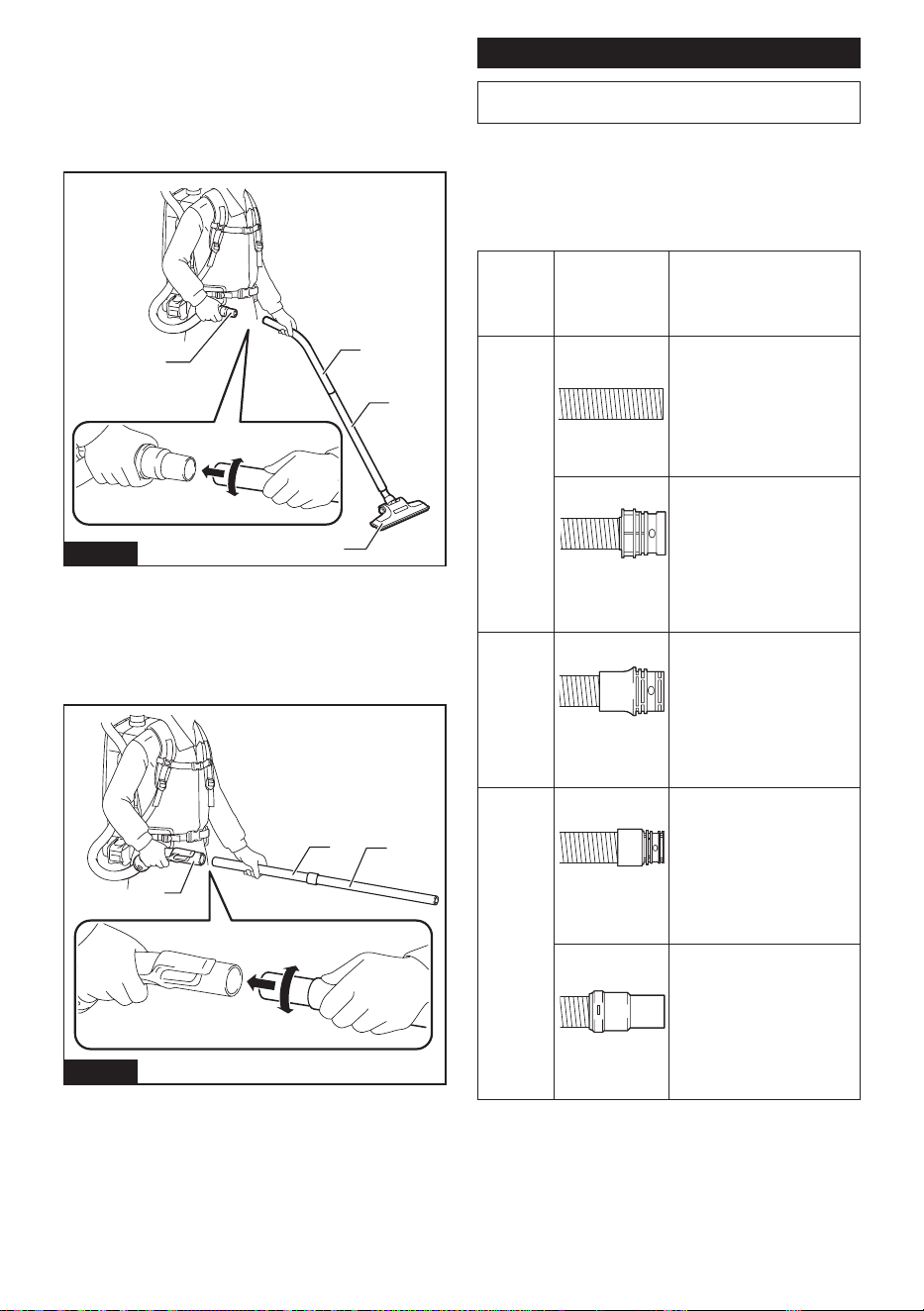
35 ESPAÑOL
Para el tubo curvo de aluminio / tubo recto de alu-
minio
(solo para el modelo con manguera de ø38 mm y boca
delantera 38)
Cárguese al hombro el cuerpo de la aspiradora, luego
gire e inserte el tubo dentro de la boca delantera. Para
desconectar, extráigalo girándolo.
1
3
2
4
Fig.23
► 1. Boca delantera 38 2. Tubo curvo de aluminio
3. Tubo recto de aluminio 4. Boquilla
Para los dos tubos rectos de aluminio
Cárguese al hombro el cuerpo de la aspiradora y a con-
tinuación inserte girando los tubos. Para desconectar,
extráigalo girándolo.
3
1
2
Fig.24
► 1. Conjunto de tubo curvo 2. Tubo recto de aluminio
1 3. Tubo recto de aluminio 2
Conexión de la herramienta
NOTA: Si el conjunto de tubo curvo está acoplado
a la manguera, extráigalo primero.
Para conectar una herramienta a la aspiradora, hacen
falta la manguera especicada y/o accesorios adiciona-
les. Dependiendo del modelo de aspiradora, necesitará
reemplazar la manguera y/o preparar los accesorios
adicionales.
Consulte la tabla a continuación para más detalles.
Diámetro
de la
manguera
suminis-
trada
Tipo de extremo
de manguera
Solución
ø28 mm
sin pieza
Acople la boca delantera.
con pieza a
presión
Reemplace el extremo de la
manguera (pieza a presión)
por la boca delantera.
El extremo de la manguera
se puede extraer girándolo
en sentido inverso al de las
manecillas del reloj.
ø32 mm
con pieza a
presión
Reemplace la manguera por
la de extracción de polvo (ø28
mm, con boca delantera).
ø38 mm
con pieza a
presión
Reemplace la manguera por
la de extracción de polvo (ø28
mm, con boca delantera).
con boca delan-
tera 38
Acople la junta 22-38 a la
boca delantera 24.
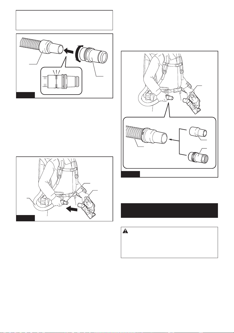
36 ESPAÑOL
NOTA: Utilice siempre una boca delantera adecuada.
Cuando utilice la boca delantera 24, acóplela a la
boca delantera 22 que se encuentra conectada a la
manguera.
1
2
Fig.25
► 1. Boca delantera 22 2. Boca delantera 24
Al utilizar la manguera de extracción
de polvo de ø28 mm
1. Acople la boca delantera a la manguera de extrac-
ción de polvo.
Cuando conecte la boca delantera, asegúrese de que
quede bien atornillada en la manguera.
2. Conecte la boca delantera a la salida de extrac-
ción de la herramienta.
1
2
3
Fig.26
► 1. Boca delantera 2. Salida de extracción
3. Manguera
La boca delantera puede desconectarse girándola en
sentido inverso al de las manecillas del reloj mientras
sostiene la manguera.
Al utilizar manguera de ø38 mm con
boca delantera 38
1. Inserte girando la junta o la boca delantera a la
pieza de entrada de la manguera, dependiendo de la
herramienta que se vaya a conectar.
2. Conecte la boca delantera a la salida de extrac-
ción de la herramienta.
1
2
3
4
Fig.27
► 1. Junta 2. Boca delantera 3. Salida de extracción
4. Manguera
Para extraer la junta y la boca delantera, siga el proce-
dimiento de instalación en orden inverso.
Instalación de la bolsa del ltro/
bolsa recolectora de polvo
Accesorio opcional
PRECAUCIÓN: No use una bolsa del ltro
dañada. Siempre utilice la aspiradora con la bolsa
del ltro instalada correctamente. De lo contrario,
el polvo o las partículas aspiradas podrían esca-
par de la aspiradora y causar una enfermedad
respiratoria al operador.
Instale ya sea una bolsa recolectora de polvo o bolsa
del ltro antes de utilizar la aspiradora.
— La bolsa recolectora de polvo se puede utilizar
varias veces, de manera repetida, si ésta se
limpia.
— La bolsa del ltro es de tipo desechable. Deseche
por completo la bolsa del ltro sin vaciarlo, cuando
ésta se haya llenado.
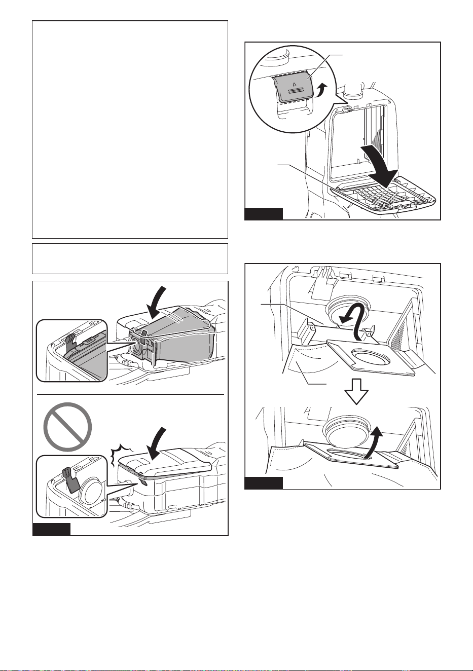
37 ESPAÑOL
AVISO: Cuando la bolsa del ltro ya esté llena,
reemplácela con una nueva. Cuando la bolsa
recolectora de polvo ya esté llena, vacíela. El uso
continuo de la bolsa del ltro/bolsa recolectora de
polvo cuando está llena ocasionará una reducción de
la potencia de succión.
AVISO: Para evitar que el polvo se introduzca en
el motor:
— Asegúrese de instalar la bolsa del ltro/
bolsa recolectora de polvo antes de su uso.
— No utilice una bolsa rota o rasgada.
De lo contrario, el motor podría averiarse.
AVISO: No doble el cartón en su abertura cuando
instale la bolsa del ltro/bolsa recolectora de
polvo.
AVISO: La bolsa del ltro/bolsa recolectora
de polvo de la aspiradora es un componente
importante para mantener el buen desempeño
del aparato. El utilizar una bolsa del ltro/bolsa
recolectora de polvo no original puede ocasionar
humo o ignición.
NOTA: Cuando la bolsa del ltro/bolsa recolectora
de polvo no se instalan en la aspiradora, la cubierta
delantera no se cierra por completo.
Fig.28
1. Desbloquee la palanca y abra la cubierta
delantera.
2
1
Fig.29
► 1. Palanca 2. Cubierta delantera
2. Inserte la bolsa del ltro en la hendidura en la
parte superior del compartimiento tal como se ilustra.
1
2
Fig.30
► 1. Hendidura 2. Bolsa del ltro
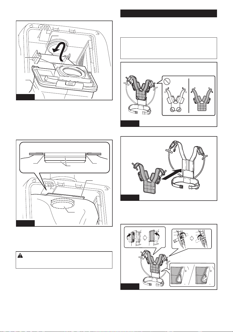
38 ESPAÑOL
Cuando utilice la bolsa recolectora de polvo, inserte su
reborde en la hendidura.
2
3
1
Fig.31
► 1. Hendidura 2. Reborde 3. Bolsa recolectora de
polvo
3. Alinee el oricio de la bolsa del ltro con la boca
de la manguera y empuje la parte de cartón hasta el
tope. Asegúrese de que la arandela de goma en la
bolsa del ltro esté por encima del reborde en la boca
de la manguera.
11
2
3
4
Fig.32
► 1. Arandela de goma en la bolsa del ltro
2. Reborde en la boca de la manguera 3. Parte de
cartón de la bolsa del ltro 4. Boca de la manguera
4. Bloquee la cubierta delantera con seguridad.
PRECAUCIÓN: Tenga cuidado de no pelliz-
car sus dedos cuando enganche la aldabilla y al
cerrar la cubierta delantera.
Cubierta del arnés
Accesorio opcional
Cuando use la cubierta del arnés, siga el procedimiento
a continuación para colocarla.
NOTA: Al instalar la cubierta del arnés, no confunda
la parte delantera y trasera de la cubierta del arnés.
NOTA: La cubierta del arnés es lavable. Siga las
instrucciones de lavado de la etiqueta.
Fig.33
1. Extienda la cubierta del arnés sobre el arnés.
Fig.34
2. Asegure las correas para los hombros del arnés
con los sujetadores de gancho y bucle de la cubierta
del arnés. Enganche la banda de la cubierta del arnés
sobre el arnés.
Fig.35
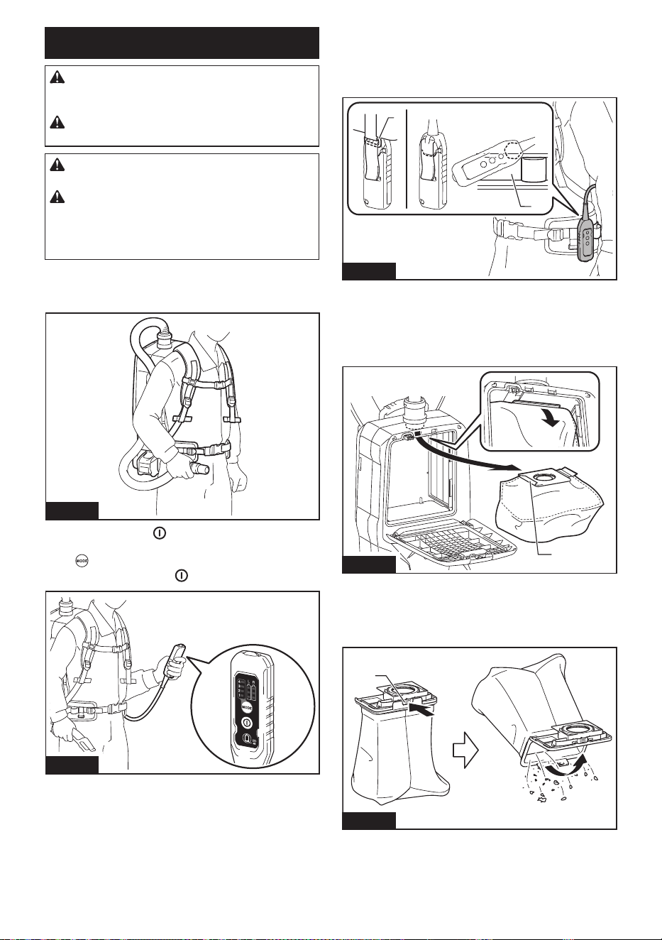
39 ESPAÑOL
OPERACIÓN
ADVERTENCIA: Los operadores deberán
recibir las instrucciones adecuadas sobre el uso
de la aspiradora.
ADVERTENCIA: Esta aspiradora no es apro-
piada para recoger polvo peligroso.
PRECAUCIÓN: Esta aspiradora está dise-
ñada exclusivamente para el uso en seco.
PRECAUCIÓN: Durante la operación, tenga
siempre en mente que lleva la aspiradora a la
espalda. Podría perder el equilibrio si el cuerpo de la
aspiradora choca contra una pared o la manguera se
engancha en algún obstáculo.
1. Cargue en su hombro el cuerpo de la aspiradora
y je las correas superior e inferior. Ajuste lo apretado
según sea necesario.
Fig.36
2. Oprima el botón
para comenzar a aspirar.
Si desea cambiar la potencia de succión, oprima el
botón hasta seleccionar la potencia de succión
deseada. Oprima el botón para parar.
Fig.37
Durante la operación, enganche la caja del interruptor
en el anillo en D o la parte para colgado de la correa
inferior. El gancho se puede inclinar para alumbrar
hacia adelante cuando está enganchado a la parte para
colgado.
1
2
Fig.38
► 1. Anillo en D 2. Parte para colgado
3. Reemplace la bolsa del ltro cuando esté llena.
Abra la cubierta delantera y extraiga la bolsa del ltro.
Jale la tira en el lado de la abertura para cerrar la bolsa
del ltro y desechar la bolsa del ltro completa.
1
Fig.39
► 1. Tira
Cuando utilice una bolsa recolectora de polvo, retire la
bolsa recolectora de polvo y deseche el polvo liberando
la aldabilla.
1
Fig.40
► 1. Aldabilla
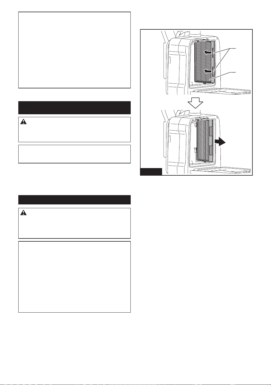
40 ESPAÑOL
AVISO: No ponga la bolsa del ltro/bolsa reco-
lectora de polvo u otros objetos pesados sobre la
cubierta delantera. El aparato podría caerse.
AVISO: Revise periódicamente la bolsa del ltro
para ver si el ltro está lleno o no. El uso continuo
de la bolsa del ltro cuando está llena ocasionará una
reducción de la potencia de succión.
AVISO: No utilice una bolsa del ltro usada.
La bolsa del ltro está diseñada para usarse una
sola vez. El uso repetido de la bolsa del ltro puede
causar el atasco del ltro y daños a la aspiradora.
Si desea utilizar la bolsa repetidamente, utilice una
bolsa recolectora de polvo.
MANTENIMIENTO
PRECAUCIÓN: Asegúrese siempre de que el
aparato haya sido apagado y que el cartucho de
batería haya sido extraído antes de intentar reali-
zar una inspección o tarea de mantenimiento.
AVISO: Nunca use gasolina, bencina, diluyente
(tíner), alcohol o sustancias similares. Puede que
esto ocasione grietas o descoloramiento.
Para mantener la SEGURIDAD y FIABILIDAD del pro-
ducto, las reparaciones, y cualquier otra tarea de man-
tenimiento o ajuste deberán ser realizadas en centros
de servicio autorizados o de fábrica Makita, empleando
siempre repuestos Makita.
Limpieza del ltro HEPA
PRECAUCIÓN: No utilice la aspiradora sin un
ltro ni continúe usando el ltro sucio o dañado.
El polvo o las partículas aspiradas podrían esca-
par de la aspiradora y causar una enfermedad
respiratoria al operador.
AVISO: Para mantener una potencia de succión
óptima y un escape limpio, limpie el ltro perió-
dicamente. Si no logra obtenerse una potencia
de succión suciente incluso después de la lim-
pieza, reemplace el ltro con uno nuevo.
AVISO: Para evitar que el ltro se dañe, no utilice
las siguientes herramientas o elementos simila-
res para limpiarlo:
— Sacudidor de aire
— Hidrolavadora de alta presión
— Herramientas hechas de materiales duros,
como cepillos de alambre
1. Abra la cubierta delantera y extraiga la bolsa del
ltro/bolsa recolectora de polvo. Libere el gancho en el
ltro y retírelo del cuerpo de la aspiradora.
1
2
Fig.41
► 1. Gancho 2. Filtro HEPA
2. Golpee el polvo del ltro. El ltro puede ser lavado
con agua. Limpie con agua el polvo y las partículas
en el ltro cada 1 o 2 meses. Después de eso, seque
por completo el ltro en un lugar a la sombra y bien
ventilado para evitar un olor desagradable o un funcio-
namiento defectuoso.
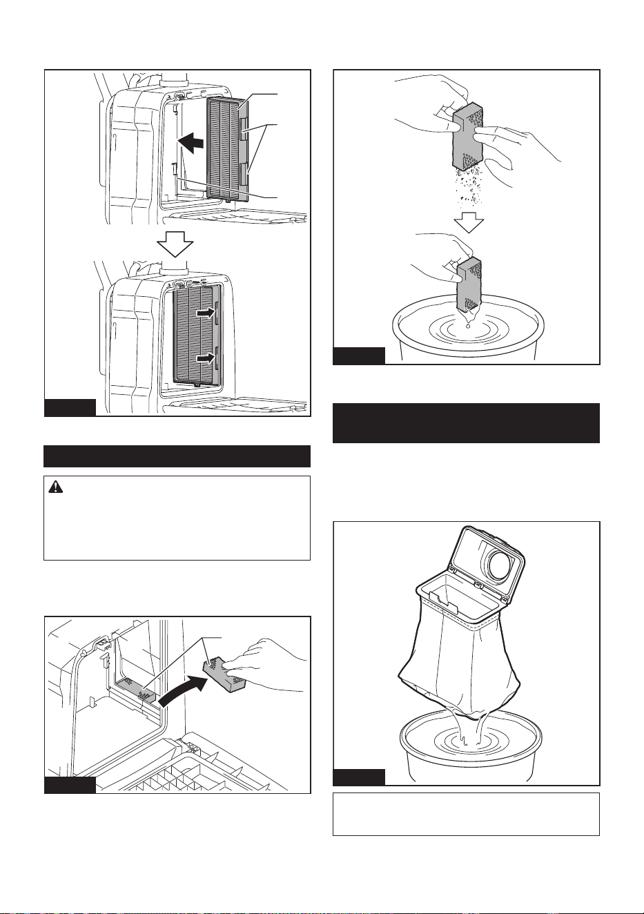
41 ESPAÑOL
3. Para instalar el ltro, inserte el lado sin los gan-
chos en la ranura y luego empuje el ltro hacia adentro
hasta que los ganchos queden asegurados con un clic.
1
2
3
Fig.42
► 1. Ranura 2. Filtro HEPA 3. Gancho
Limpieza del ltro de esponja
PRECAUCIÓN: Después de limpiar los l-
tros de esponja, asegúrese de instalarlos en la
aspiradora. Si se lava en agua, séquelos bien antes
de instalarlos. Los ltros de esponja que no estén
completamente secos podrían acortar la vida útil del
motor.
Los ltros de esponja debajo del ltro HEPA evitan que
entre polvo en el motor.
1. Retire los ltros de esponja de la aspiradora.
1
Fig.43
► 1. Filtro de esponja
2. Limpie y sacuda el polvo de los ltros de esponja
con la mano. Cuando los ltros de esponja estén obs-
truidos, lávelos con agua jabonosa.
Fig.44
3. Instale los ltros de esponja en su posición
original.
Limpieza de la bolsa recolectora de
polvo
Limpie regularmente la bolsa recolectora de polvo con
agua y jabón. Voltee al revés la bolsa recolectora de
polvo y retire el polvo adherido. Lávela ligeramente con
la mano y enjuague bien con agua. Séquela por com-
pleto antes de instalarla en la aspiradora.
Fig.45
AVISO: Una bolsa recolectora de polvo húmeda
reduce el desempeño del aspirado así como la vida
del motor.
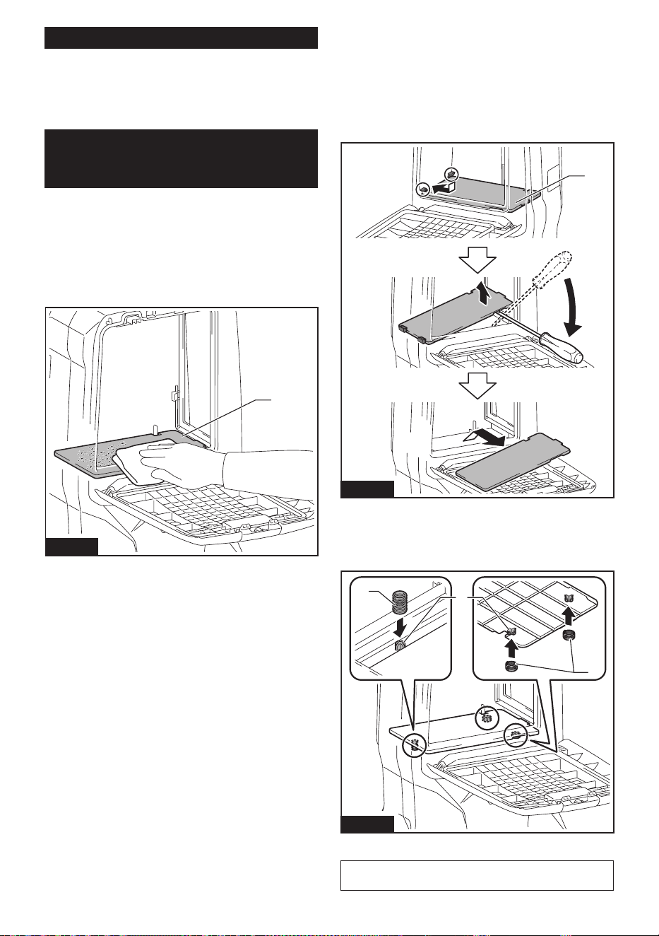
42 ESPAÑOL
Reparar un atascamiento
Para reparar los atascamientos, extraiga la manguera
o el tubo de extensión o el conjunto de tubo curvo para
comprobar su interior.
Consulte la sección para colocar el conjunto de tubo
curvo.
Limpieza del espacio interior de la
bolsa del ltro/bolsa recolectora de
polvo
Este aparato está equipado con un sistema para sacu-
dir de polvo. A medida que camina mientras lleva la
aspiradora, los resortes debajo del tablero hacen vibrar
el tablero y sacuden el polvo de la bolsa del ltro/bolsa
recolectora de polvo.
Cuando limpie el espacio interior de la bolsa del ltro/
bolsa recolectora de polvo, extraiga y limpie el tablero
del interior.
1
Fig.46
► 1. Tablero
Extracción del tablero
1. Extraiga el ltro HEPA. Consulte la sección de
limpieza del ltro HEPA para ver cómo se retira.
2. Empuje hacia abajo el tablero y deslícelo hacia la
izquierda hasta que el tablero toque la pared.
3. Levante el lado derecho del tablero hacia arriba y
sáquelo hacia afuera.
1
Fig.47
► 1. Tablero
El tablero está sostenido mediante tres resortes.
Si los resortes se desprendieron de las proyecciones,
vuelva a colocarlos como se muestra en la ilustración.
2
3
1
Fig.48
► 1. Resorte largo 2. Resorte corto 3. Protuberancia
NOTA:
Fije los resortes de forma segura de modo que
los resortes toquen la base de las protuberancias.
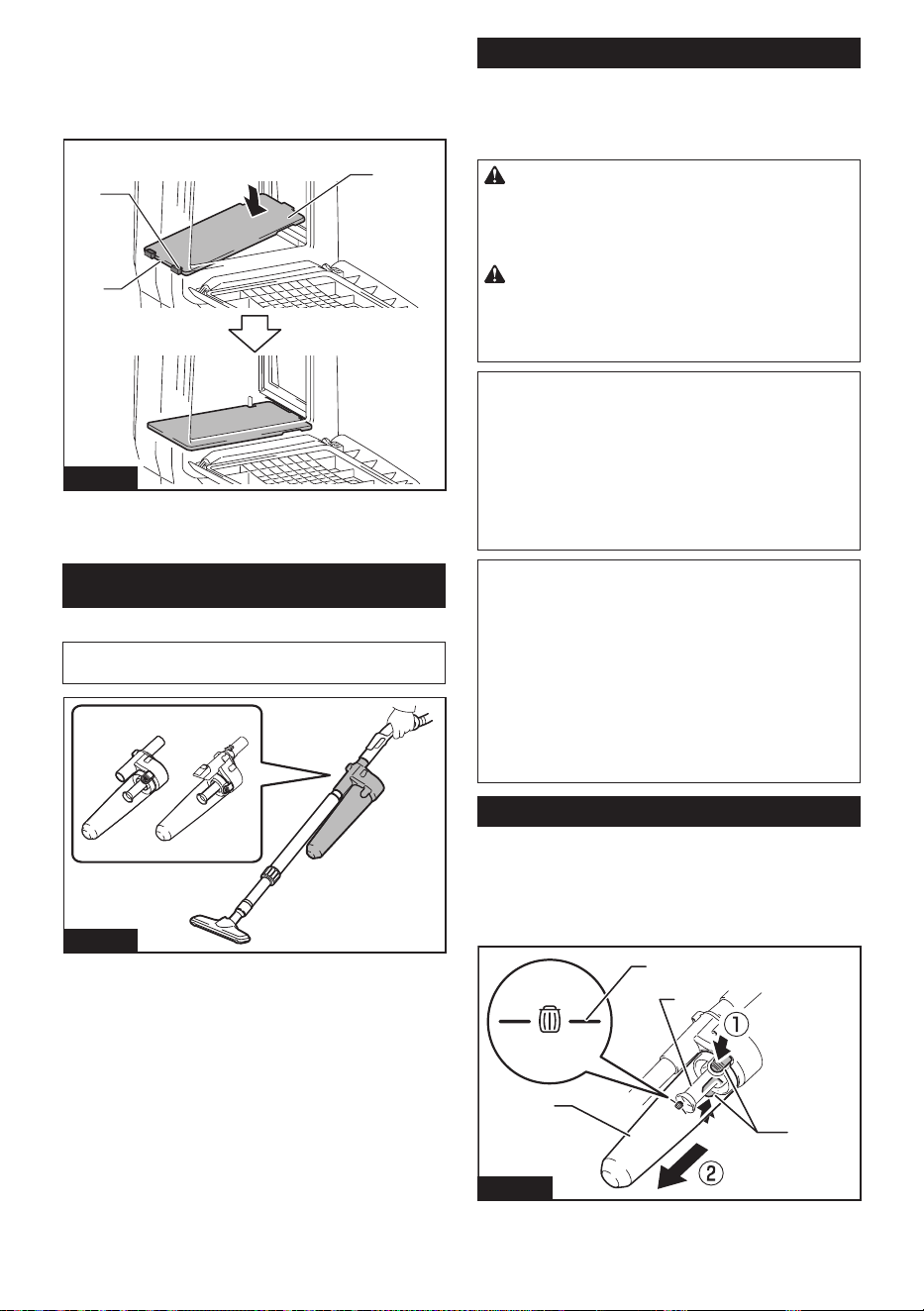
43 ESPAÑOL
Fijación del tablero
1. Coloque el lado recto del tablero en los sujetado-
res en el lado inferior izquierdo del espacio interior.
2. Ponga el lado derecho del tablero en su sitio.
2
1
3
Fig.49
► 1. Tablero 2. Lado recto 3. Sujetador
COLECTOR CICLÓNICO
Accesorio opcional
NOTA: Cuando utilice el colector ciclónico con este
aparato, también se requiere el tubo curvo.
1
Fig.50
► 1. Colector ciclónico
Acerca del colector ciclónico
El uso de la aspiradora con el colector ciclónico instalado
reduce la cantidad de polvo que ingresa a la bolsa recolectora
de polvo, lo que ayuda a evitar que la fuerza de succión se
debilite. Además, limpiarla después de su uso es algo sencillo.
PRECAUCIÓN:
Asegúrese siempre de que la herra-
mienta esté apagada y el cartucho de batería haya sido
extraído antes de realizar cualquier trabajo en la misma. Si
se deja insertado el cartucho de batería, la aspiradora podría
arrancar de forma inesperada y ocasionar una lesión.
PRECAUCIÓN: Limpie el ltro de malla del
colector ciclónico y la bolsa recolectora de polvo
de la unidad de la aspiradora cuando se obstru-
yan. El uso continuo en la condición obstruida podría
provocar su calentamiento o humo.
AVISO: Cuando se coloca el colector ciclónico,
no use el colector ciclónico en la posición hori-
zontal u orientada hacia arriba. El hacerlo podría
ocasionar que el ltro de malla se obstruya.
AVISO: Siempre utilice la aspiradora con la bolsa
recolectora de polvo instalada, incluso cuando
utiliza el colector ciclónico. Si se utiliza la aspira-
dora sin la bolsa recolectora de polvo instalada se
podría ocasionar una avería del motor.
NOTA: Verique que el colector ciclónico, la aspira-
dora y el tubo recto estén asegurados correctamente
antes de su uso.
NOTA:
Vacíe la caja para polvo del colector cicló-
nico y la bolsa recolectora de polvo de la aspiradora
cuando se haya acumulado el polvo. El uso continuo
en esas circunstancias debilitará la fuerza de succión.
NOTA: Puede utilizar el colector ciclónico con o sin la
función de bloqueo.
NOTA: Para instalar o desinstalar el colector cicló-
nico, consulte la sección “Uso como aspiradora”.
Eliminación del polvo
Cuando se haya acumulado el polvo hasta la línea de
llenado completo de la caja para polvo, siga el procedi-
miento a continuación y deseche el polvo.
1.
Sujete la caja para polvo rmemente, oprima y man-
tenga apretados los dos botones y extraiga la caja para polvo.
2
3
1
4
Fig.51
► 1. Línea de llenado completo 2. Caja para polvo
3. Botón (dos ubicaciones) 4. Filtro de malla
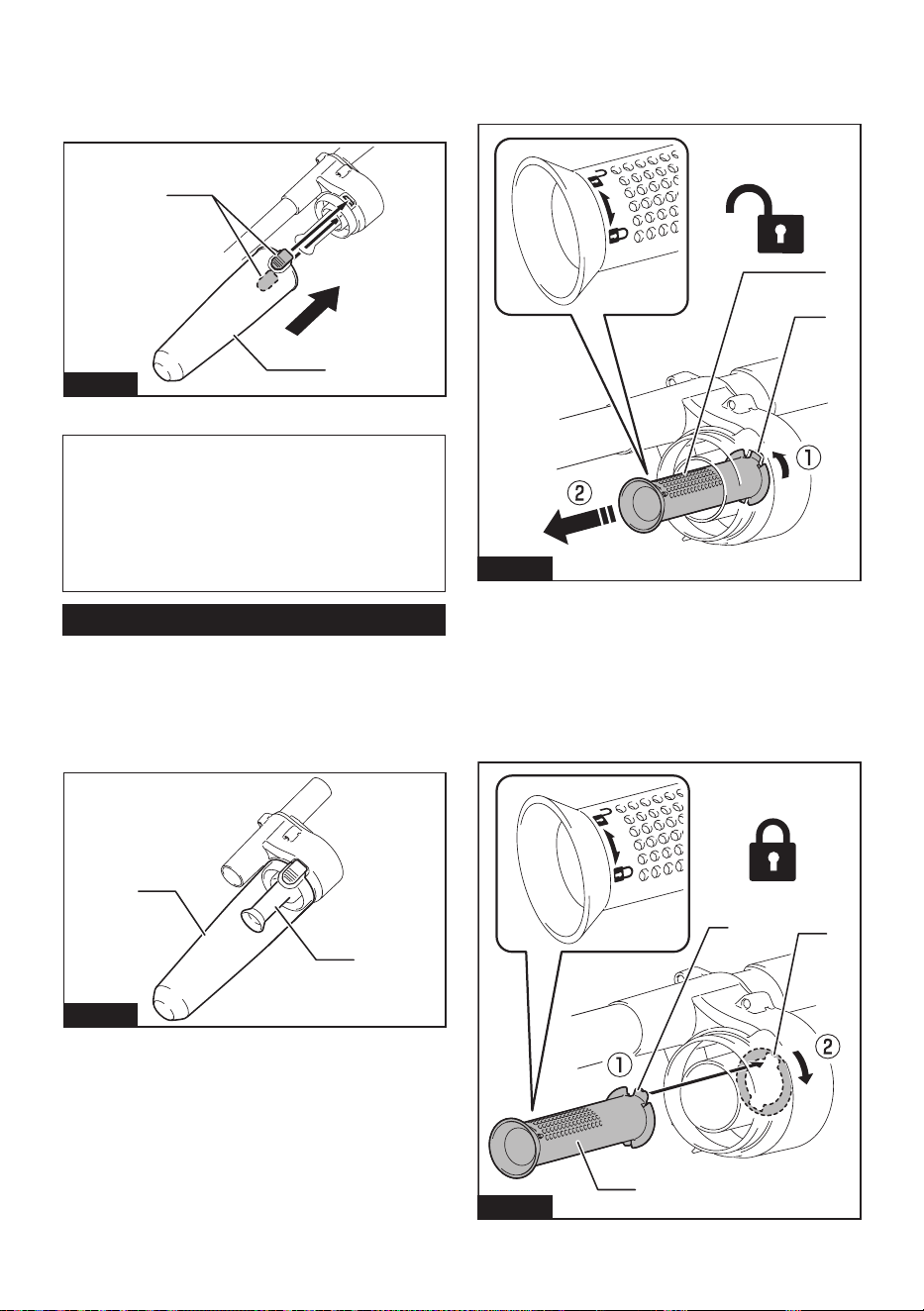
44 ESPAÑOL
2. Deseche el polvo dentro de la caja para polvo
y extraiga cualquier polvo y partículas adheridas a la
supercie del ltro de malla.
3. Inserte la caja para polvo hasta el fondo hasta que
los dos botones queden asegurados con un clic.
2
1
Fig.52
► 1. Caja para polvo 2. Botón (dos ubicaciones)
NOTA: Verique que el colector ciclónico, la aspira-
dora y el tubo recto estén asegurados correctamente
antes de reiniciar la operación.
NOTA: Si la fuerza de succión no se recupera incluso
después de desechar el polvo y de limpiar el ltro
de malla, verique si se ha acumulado polvo en la
bolsa recolectora de polvo de la aspiradora o si hay
obstrucción.
Limpieza
Cuando la caja para polvo se ensucia o el ltro de malla
se obstruye, quítelos y lávelos con agua. (Consulte la
sección “Eliminación del polvo” para el procedimiento
de eliminación).
Seque las piezas por completo antes de reinstalarlas
y usarlas.
1
2
Fig.53
► 1. Caja para polvo 2. Filtro de malla
Cuando el ltro de malla se ensucie en exceso, límpielo
con los siguientes procedimientos.
1.
Gire el ltro de malla en el sentido contrario a las manecillas
del reloj y retírelo mientras los ganchos no están asegurados.
1
2
Fig.54
► 1. Filtro de malla 2. Gancho
2.
Retire el polvo en el ltro de malla y posteriormente
lávelo con agua. Después de esto, séquelo por completo.
3.
Inserte el ltro de malla dentro de la base mien-
tras los ganchos están alineados con el puerto. Mueva
el ltro de malla en el sentido de las manecillas del
reloj hasta que los ganchos se aseguren con un clic.
Asegúrese de que el ltro de malla quede bien instalado.
2
1
3
Fig.55
► 1. Filtro de malla 2. Gancho 3. Puerto

45
ACCESORIOS
OPCIONALES
PRECAUCIÓN: Estos accesorios o aditamen-
tos están recomendados para utilizarse con su
producto de Makita especicado en este manual.
El uso de cualquier otro accesorio o aditamento
puede ocasionar riesgo de lesiones personales. Use
los accesorios o aditamentos sólo para los propósitos
para los que fueron diseñados.
Es posible que algunos accesorios no se instalen de
acuerdo con la combinación de piezas.
Si necesita cualquier ayuda para más detalles en
relación con estos accesorios, pregunte a su centro de
servicio local Makita.
• Manguera (para el tipo aspiradora)
• Manguera (para el tipo extractor de polvo)
• Tubo de extensión
• Boquilla exible de caucho
• Boquilla T
• Boquilla para asientos
• Boquilla para esquinas
• Cepillo para estantes
• Cepillo redondo
• Conjunto de tubo curvo
• Bolsa del ltro
• Bolsa recolectora de polvo
• Boca delantera
• Filtro HEPA
• Tubo
• Cubierta del arnés
• Colector ciclónico
• Batería y cargador originales de Makita
NOTA: Algunos de los artículos en la lista pueden
incluirse en el paquete de la herramienta como acce-
sorios estándar. Éstos pueden variar de país a país.
GARANTÍA LIMITADA DE
MAKITA
Ésta Garantía no aplica para México
Consulte la hoja de la garantía anexa para ver los
términos más vigentes de la garantía aplicable a este
producto. En caso de no disponer de esta hoja de
garantía anexa, consulte los detalles sobre la garantía
descritos en el sitio web de su país respectivo indicado
a continuación.
Estados Unidos de América: www.makitatools.com
Canadá: www.makita.ca
Otros países: www.makita.com
ESPAÑOL

46

47

Some dust created by power sanding, sawing, grinding, drilling, and other
construction activities contains chemicals known to the State of California
to cause cancer, birth defects or other reproductive harm. Some examples
of these chemicals are:
• lead from lead-based paints,
• crystalline silica from bricks and cement and other masonry products, and
• arsenic and chromium from chemically-treated lumber.
Your risk from these exposures varies, depending on how often you do this
type of work. To reduce your exposure to these chemicals: work in a well
ventilated area, and work with approved safety equipment, such as those
dust masks that are specially designed to filter out microscopic particles.
WARNING
< USA only >
ADVERTENCIA
Algunos polvos creados por el lijado, aserrado, esmerilado, taladrado y
otras actividades de la construcción contienen sustancias químicas
reconocidas por el Estado de California como causantes de cáncer, defectos
de nacimiento y otros peligros de reproducción. Algunos ejemplos de estos
productos químicos son:
• plomo de pinturas a base de plomo,
• sílice cristalino de ladrillos y cemento y otros productos de albañilería, y
• arsénico y cromo de maderas tratadas químicamente.
El riesgo al que se expone varía, dependiendo de la frecuencia con la que
realice este tipo de trabajo. Para reducir la exposición a estos productos
químicos: trabaje en un área bien ventilada y póngase el equipo de seguridad
indicado, tal como las máscaras contra polvo que están especialmente
diseñadas para filtrar partículas microscópicas.
< Sólo en los Estados Unidos >
Makita Corporation
3-11-8, Sumiyoshi-cho,
Anjo, Aichi 446-8502 Japan
www.makita.com
885A49-942
GCV08-1
EN, ESMX
20230808
