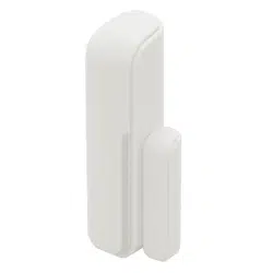
Embedded&Door&Sensor&
Model&SS881ZB&
&
&
&
User's&Manual&
For other language versions, please visit: www.salusinc.com

ii& Salus&
User's&Manual&
CONTENTS'
SAFETY INSTRUCTIONS II!
PRODUCT INTRODUCTION 1!
IN THE BOX 1!
CONTROLS AND INDICATORS 2!
LED INDICATIONS 2!
INSTALLING THE SENSOR 3!
TOOLS 3!
PAIRING THE SENSOR 3!
INSTALLING THE SENSOR 4!
TESTING THE SENSOR 5!
USING THE SENSOR 5!
CHANGING THE BATTERY 6!
BATTERY DISPOSAL 6!
RESET TO DEFAULTS 6!
SPECIFICATIONS 7!
TROUBLESHOOTING 7!
REGULATORY DECLARATIONS 8!
FCC STATEMENTS 8!
FCC AND INDUSTRY CANADA 8!
INDUSTRY CANADA 8!
SALUS WARRANTY 9!
'SAFETY'INSTRUCTIONS'
Please read these instructions carefully before installing and using
the Embedded Door Sensor, and keep this guide in a safe place for
future reference.
• Verify compatibility with your associated connected home
system before installation.
• Follow all instructions provided by your connected home
manufacturer regarding the addition of devices to your
connected home system. An authorized, qualified installer may
be required.
Salus accepts no responsibility for damage caused by not following
these instructions.
Embedded&Door&Sensor& 1&
Version&1&
PRODUCT'INTRODUCTION'
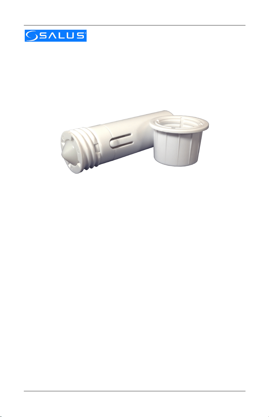
The Salus Embedded Door Sensor is a ZigBee HA 1.2 compatible
sensor used primarily to detect the opening and closing of a door. It
is installed in the door frame so that it is hidden from view and does
not detract from the room’s décor.
Key features include:
• Quick and easy installation without special tools
• Adjusts for door-to-frame gaps up to 1/4 inch
• Tamper switch to detect removal
• Hidden installation does not distrupt room’s décor
• ZigBee™ wireless technology for connected home systems
• 42-month battery life under normal usage
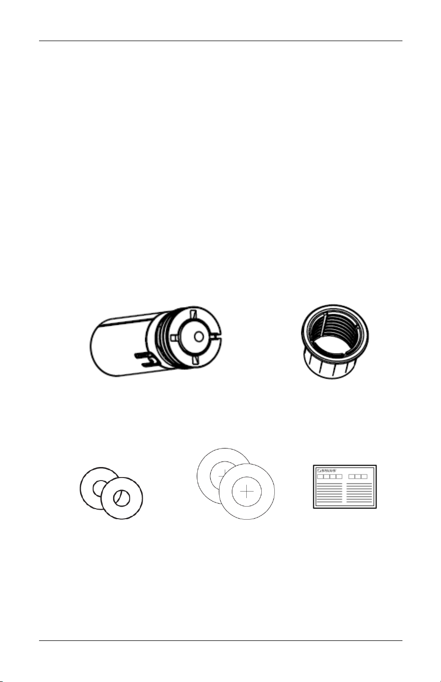
IN'THE'BOX'
Embedded Door Sensor w/ Battery
(1x CR2 3V lithium)
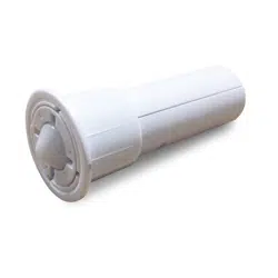
Sensor Sleeve
Installation Tool (2pcs)
Drill Stickers (2pcs)
Quick Start Guide
2& Salus&
User's&Manual&
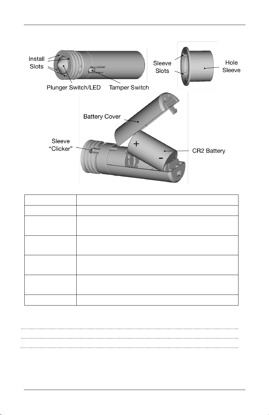
CONTROLS'AND'INDICATORS'
Item
Description
Install Slots
Slots allow Installation Tool to rotate sensor
Plunger
Switch/LED
Switch detects open/close state of door or
window. LED under plunger provides status.
Tamper
Switch
Switch detects when sensor is removed from
Hole Sleeve
Hole Sleeve
Inserted in hole and allows sensor height to be
adjusted by rotating sensor
Sleeve
“Clicker”
Aligns with Sleeve Slots to limit unwanted
rotation of the sensor
Battery Cover
Protects and allows access to the lithium battery
LED'Indications'
Solid at power up:
Initializing and checking for Factory Reset
3 flashes then pause:
Searching for network to join
'
Embedded&Door&Sensor& 3&
Version&1&
INSTALLING'THE'SENSOR'
There are three basic steps to installing the sensor
• Pair the sensor to the connected home system
• Install the sensor at the desired location
• Test the sensor
Tools'
You will need the following tools to install the Embedded Door
Sensor.
• 7/8” drill bit
• Drill
• Rubber mallet
• Pliers (optional)
Pairing'the'Sensor'
Follow your connected home system’s instructions to prepare to add
devices to the system.
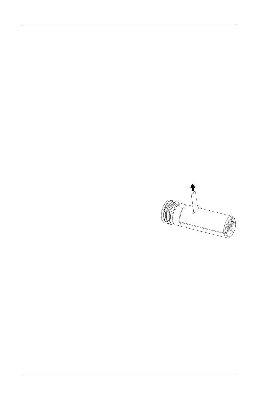
Once ready to add, go to where the
sensor is being installed to account for
any radio interference and pull the
battery tab to start the pairing process.
When the sensor is powered up, the LED
will blink three times followed by a short pause before repeating the
three blinks to indicate that it is searching for a network. If the Sensor
does not blink, you may need to reset the sensor to factory defaults.
See the Reset to Defaults section for instructions if required.
Depending on your connected home system, you may need to trip
the plunger switch or the tamper switch to complete the pairing
process. Press and release the Plunger once or twice to verify that
the connected home system registers the close and open messages.
Please refer to the system’s instructions for how to find out the state
of the sensor.
Once pairing is complete, you can install the sensor at the desired
location. See the Troubleshooting section if you encounter problems
pairing the sensor.
4& Salus&
User's&Manual&
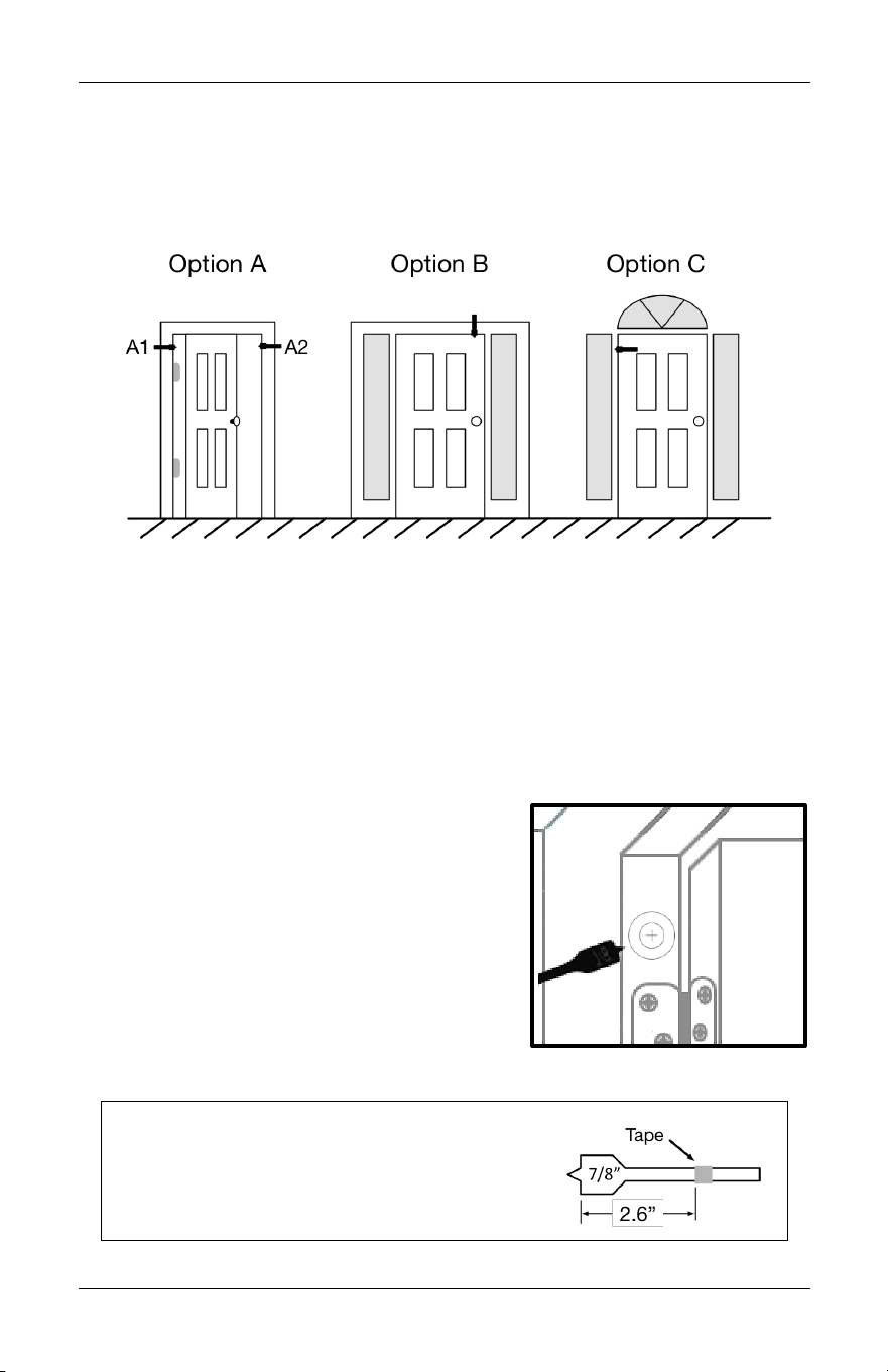
Installing'the'Sensor'
There are a variety of options for mounting the Embedded Door
Sensor depending on the configuration of the door and surrounding
frame as shown in the figure below.
The preferred location is Option A1 above, in the door jamb on the
hinge side of the door. Option A2 is also suitable if the frame does
not allow locating the sensor on the hinge side.
If space is not available in the door frame, the sensor can be
mounted in the lintel above the door on the handle side (Option B),
or in the door itself (Option C). Option C is not recommended if you
have a metal door as it would interfere with the radio signals.
Once the location has been identified,
mark the location with a Drill Sticker,
making sure that the inner circle is
centered on the surface that faces the
side of the door directly.
Drill a 7/8” hole at least 2.6” deep
through the sticker, making sure the
hole is straight into the door jamb. Clear
out any debris in the hole.
Tip: Mark the drill bit with tape 2.6 inches
from the front edge of the blades and
stop drilling when the tape is even with
the surface of the jamb.
Embedded&Door&Sensor& 5&
Version&1&
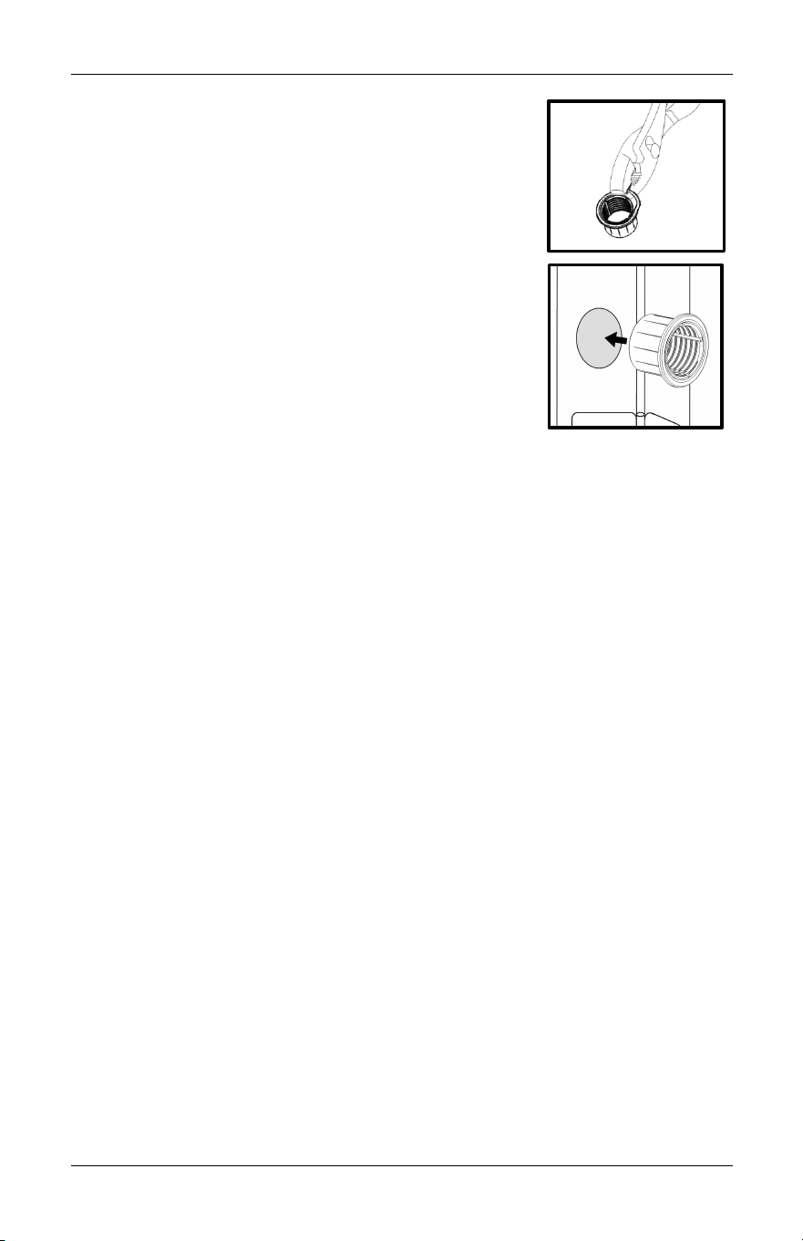
Close the door and note the size of the gap
between the door and the jamb. If it is less than
1/16 inch (the thickness of a penny), then you
will need to remove the flange from the Sensor
Sleeve with a pair of pliers.
Next, insert the Sensor Sleeve into the hole and
use the rubber mallet to make sure the Sensor
Sleeve is fully inserted.
Insert the Sensor into the Sensor Sleeve and
screw the Sensor into the sleeve until the
distance from the front of the sensor to the
jamb surface is slightly less than the size of the
gap noted earlier.
You may need the Installation Tool or a coin to properly adjust the
sensor depth. To use the tool, align the edge of the tool with
opposing Install Slots on the front of the sensor and insert into the
slots, pushing the Plunger down as you do so. Once in the slots,
rotate clockwise to move the Sensor into the Sensor Sleeve and
counter-clockwise to move the Sensor out of the Sensor Sleeve.
Testing'the'Sensor'
Once the Sensor is installed, test the Sensor by opening and closing
the door, and verifying that the connected home system registers the
activity.
If the activity is not being registered, 1) verify that when the door is
closed, it is pushing the plunger into the rest of the sensor and that
the plunger is extended when the door is open, and 2) there is
nothing in the wall between the sensor and the connected home
system receiver that would block the radio signal.
USING'THE'SENSOR'
There are no user configurable options in the sensor, so aside from
battery changes (low battery messages are sent to the connected
home system), no further interaction with the sensor is required.
6& Salus&
User's&Manual&
CHANGING'THE'BATTERY'
Use only Duracell DL-CR2, Rayovac RL-CR2, Energizer EL1CR2, or GP
Batteries GPCR2 batteries to meet UL certification requirements.
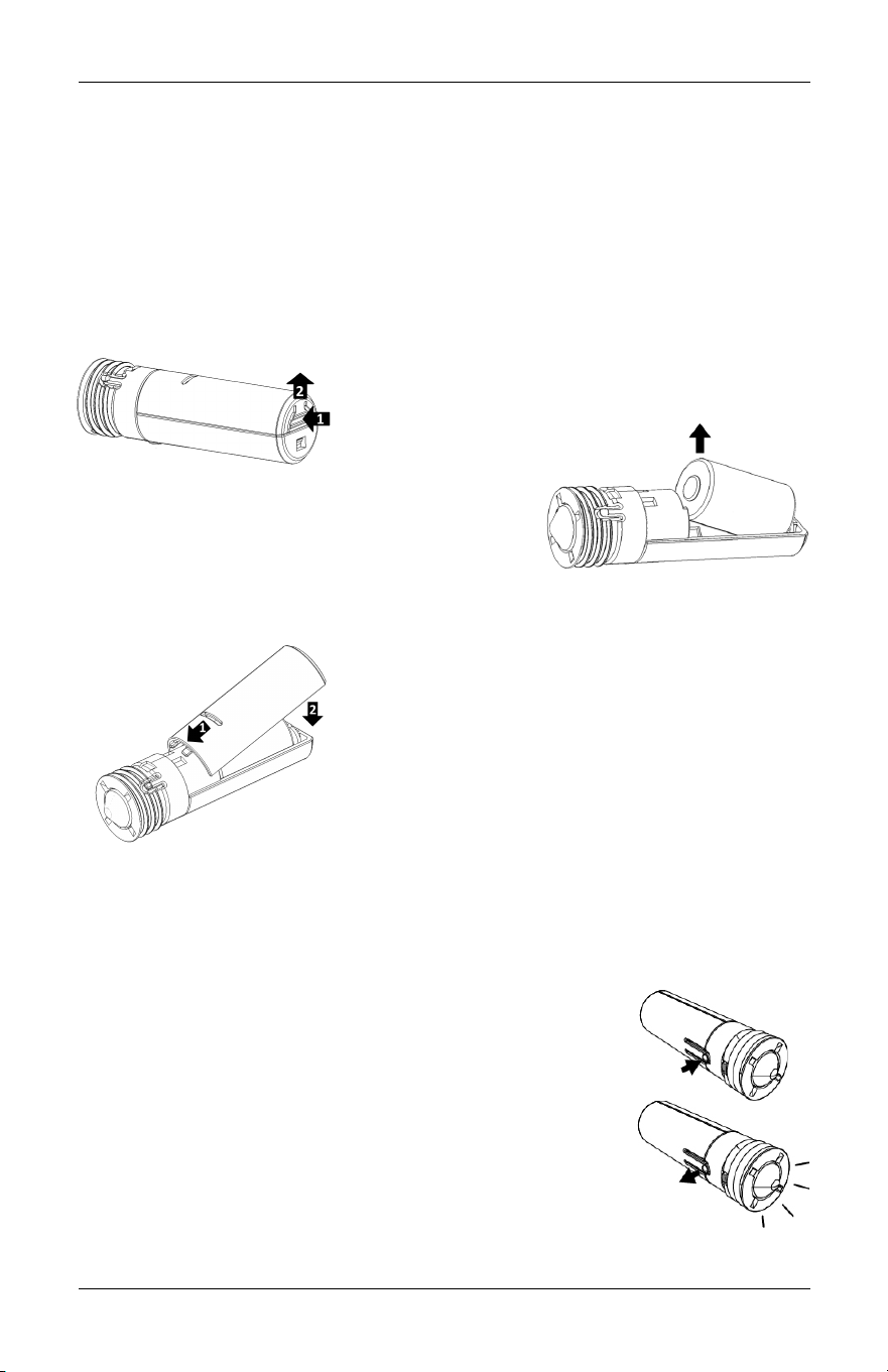
To change the battery, note the depth of the Sensor relative to the
Sensor Sleeve and remove the Sensor from the Sensor Sleeve by
rotating the Sensor counter-clockwise until the Sensor is loose. The
Installation Tool or a coin may be required.
Once the Sensor is removed, press on the
back of the Battery Cover and lift up to
remove the
cover.
Grasp the front/positive end of the old
battery to remove from the Sensor.
Insert the battery negative end first and
drop the positive end into place in the sensor.
Replace the battery cover by inserting
the front of the battery cover under the
retainers and snapping the back of the
cover into the sensor housing.
Battery'Disposal'
Lithium batteries are considered
hazardous waste in most municipalities.
Please dispose of the used batteries in accordance with the
regulations for your municipality.
RESET'TO'DEFAULTS'
To reset the Sensor to factory defaults, remove the
Sensor from the Sensor Sleeve and remove the
battery. While holding down the Tamper Switch, re-
insert the battery and release the Tamper Switch
when the LED lights up. The Sensor is now reset to
defaults and will enter pairing mode to join a
network.
Replace the battery cover and re-install the Sensor
in the Sensor Sleeve at the original depth.

Embedded&Door&Sensor& 7&
Version&1&
SPECIFICATIONS
Operating temperature
32 - 113°F / 0 - 45°C
Operating humidity
20 - 90% non-condensing
Storage
-4 - 185 °F / -20 – 85°C
20 - 90% non-condensing
Protocols Supported
ZigBee HA 1.2 Profile
OpenHome
RF frequency
2.40-2.48 GHz
RF range
Up to 1300 ft (400 m) line of sight
Battery Power
1 x CR2 3V Lithium battery
(Use only Duracell DL-CR2, Rayovac RL-CR2,
Energizer EL1CR2, or GP Batteries GPCR2
batteries)
Thread Pitch
10 threads per inch
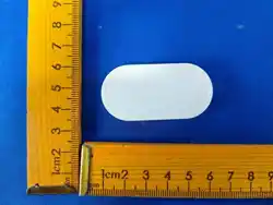
Size
Sensor:
67 (L) x 20 (D) mm
2.64” (L) x 0.78” (D)
Sleeve:
19 (L) x 28 (D) mm
0.75” (L) x 1.1” (D)
Weight without battery
0.43 oz. (12 g)
TROUBLESHOOTING'
Will not pair initially
Radio interference is present for the desired
location. Possible solutions:
• Relocate the ZigBee receiver
• Select a different location for the sensor
• Add a ZigBee repeater to the system
Does not detect
door opening and
closing
• Check connected home system for low battery
messages. Replace battery if required.
• Verify sensor depth is correct, and has not
changed since installation.
• Verify that there is no radio interference within
the walls. If so, try possible solutions above for
radio interference.
Loses connection
after pairing
• Check connected home system for low battery
messages. Replace battery if required.
• Radio environment may have changed. Apply
radio interference solutions above.
Multiple events per
door open/close
Adjust depth by a quarter turn counter-clockwise to
eliminate border line condition.
'

8& Salus&
User's&Manual&
REGULATORY'DECLARA TIONS'
FCC'Statements'
WARNING: Changes or modifications to this unit not expressly approved by the party
responsible for compliance could void the user’s authority to operate the equipment.
This device complies with Part 15 of the FCC Rules. Operation is subject to the
following two conditions: (1) this device may not cause harmful interference, and (2)
this device must accept any interference received, including interference that may
cause undesired operation.
NOTE: This equipment has been tested and found to comply with the limits for a Class
B digital device, pursuant to Part 15 of the FCC Rules. These limits are designed to
provide reasonable protection against harmful interference in a residential installation.
This equipment generates, uses and can radiate radio frequency energy, and if not
installed and used in accordance with the instructions, may cause harmful interference
to radio communications. However, there is no guarantee that interference will not
occur in a particular installation. If this equipment does cause harmful interference to
radio or television reception, which can be determined by turning the equipment off
and on, the user is encouraged to try to correct the interference by one or more of the
following measures:
• Reorient or relocate the receiving antenna.
• Increase the separation between the equipment and receiver.
• Connect the equipment into an outlet on a circuit different from that to which the
receiver is connected.
• Consult the dealer or an experienced radio/TV technician for help.
FCC'and'Industry'Canada'
RF Radiation Exposure statement: This equipment complies with FCC and Industry
Canada RF radiation exposure limits set forth for an uncontrolled environment. This
equipment should be installed and operated with a minimum distance of 20
centimeters between the antenna and all persons.
Industry'Canada'
Under Industry Canada regulations, this radio transmitter may only operate using an
antenna of type and maximum (or lesser) gain approved for the transmitter by
Industry Canada. To reduce potential radio interference to other users, the antenna
type and its gain should be so chosen that the equivalent isotropically radiated power
(e.i.r.p.) is not more than that necessary for successful communication.
This device complies with Industry Canada licence-exempt RSS standard(s). Operation
is subject to the following two conditions: (1) this device may not cause interference,
and (2) this device must accept any interference, including interference that may cause
undesired operation of the device.
Le présent appareil est conforme aux CNR d'Industrie Canada applicables aux
appareils radio exempts de licence. L'exploitation est autorisée aux deux conditions
suivantes : (1) l'appareil ne doit pas produire de brouillage, et (2) l'utilisateur de
l'appareil doit accepter tout brouillage radioélectrique subi, même si le brouillage est
susceptible d'en compromettre le fonctionnement.

Embedded&Door&Sensor& 9&
Version&1&
SALUS'WARRANTY'
Salus Controls Inc. (“Salus”) warrants that for a period of two (2) years (“Warranty
Period”) from the date of purchase by the consumer (“Customer”), this device,
excluding batteries (“Product”), shall be free of defects in materials and workmanship
under normal use and service in accordance with all supplied instructions. During the
warranty period, Salus shall, at its option, repair or replace any defective Products, at
no charge for the device. Any replacement and/or repaired devices are warranted for
the remainder of the original Warranty Period or ninety (90) days, whichever is longer.
This warranty does not cover removal or reinstallation costs. This warranty does not
apply to any Product (i) which has been modified, repaired, or altered, except by Salus
or an authorized Salus representative, (ii) which has not been maintained in
accordance with any handling or operating instructions supplied by Salus, or (iii) which
has been subjected to unusual physical or electrical stress, misuses, abuse, negligence
or accidents.
This warranty is the only express warranty Salus makes for the Product. Any implied
warranties, including warranties of merchantability or fitness for a particular purpose,
are limited to the Warranty Period or the shortest period allowed by law.
SALUS SHALL NOT BE LIABLE FOR ANY LOSS OR DAMAGE OF ANY KIND, INCLUDING
ANY SPECIAL, INCIDENTAL OR CONSEQUENTIAL DAMAGES RESULTING, DIRECTLY OR
INDIRECTLY, FROM ANY BREACH OF ANY WARRANTY, EXPRESS OR IMPLIED, OR ANY
OTHER FAILURE OF THIS PRODUCT. Some states and provinces do not allow the
exclusion or limitation of incidental or consequential damages, or limitation on the
duration of implied warranties of merchantability or fitness, so these exclusions or
limitations may not apply to you.
No oral or written information or advice given by Salus or a Salus-authorized
representative shall modify or extend this warranty. If any term is held to be illegal or
unenforceable, the legality or enforceability of the remaining terms shall not be
affected or impaired.
Customer’s sole and exclusive remedy under this limited warranty is product repair or
replacement as provided herein. If a Product under warranty is defective, the
Customer may:
• contact the party (“Seller”) from which the Customer purchased the Product to
obtain an equivalent replacement product after the Seller has determined that
the Product is defective and the Customer is eligible for a replacement, or,
• contact Salus Service at 4700 Duke Drive, Suite 200, Mason, OH 45040, to
determine whether the device qualifies for a replacement. If a replacement is
warranted and is shipped prior to the return of the device under warranty, a
credit card is required and a hold may be placed on the Customer’s credit card for
the value of the replacement until the returned device is verified as eligible for
replacement, in which case, the Customer’s credit card will not be charged.
This warranty gives you specific legal rights, and you may also have other rights that
vary from jurisdiction to jurisdiction. If you have any questions regarding this warranty,
please write Salus at:
850 Main Street.
Redwood City, CA 94063

&
Version&1&
Salus Controls Inc.
850 Main Street
Redwood City, CA 94063