Warning notices: Before using this product, please read this manual carefully and keep it for future reference.
The design and specifications are subject to change without prior notice for product improvement.
Consult with your dealer or manufacturer for details.
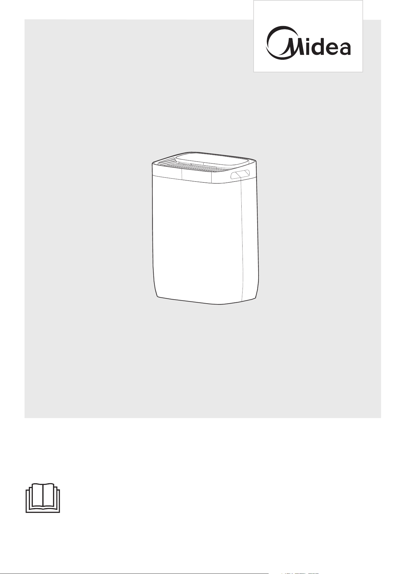
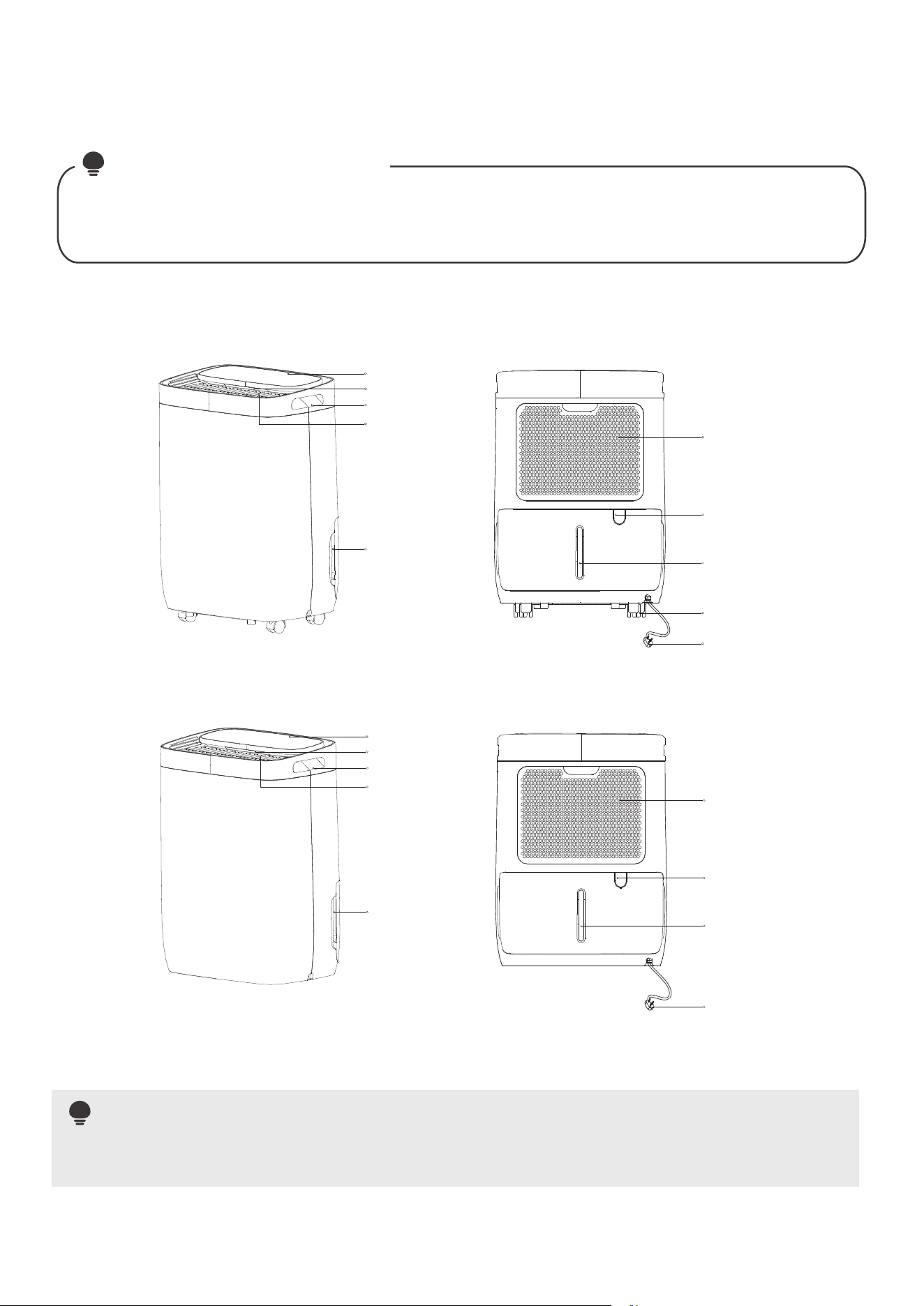
The diagram above is just for reference. Please take the appearance of the actual product as the standard.
MODEL NUMBER
MDDQ1-12DEN7-QA3
USER MANUAL
DEHUMIDIFIER


THANK YOU LETTER
Thank you for choosing Midea! Before using your new Midea product, please
read this manual thoroughly to ensure that you know how to operate the
features and functions that your new appliance ofers in a safe way.
01
CONTENTS
01
02
10
1 1
12
13
15
19
20
21
21
22
THANK YOU LETTER
SAFETY PRECAUTIONS
SPECIFICATIONS
PRODUCT OVERVIEW
CONFIRM IT BEFORE YOU GET START
REMOVING THE COLLECTED WATER
OPERATION INSTRUCTIONS
CLEANING AND MAINTENANCE
TROUBLESHOOTING
TRADEMARKS, COPYRIGHTS AND LEGAL STATEMENT
DISPOSAL AND RECYCLING
DATA PROTECTION NOTICE
It’s really important you read Safety Precautions Before Operation and Installation
Incorrect installation due to ignoring instructions can cause serious damage or injury.
The seriousness of potential damage or injuries is classified as either a WARNING
or CAUTION.
SAFETY PRECAUTIONS
Read these operating instructions carefully and attentively before using/commis-
sioning the unit and keep them in the immediate vicinity of the installation site or
unit for later use!
WARNING
The signal word indicates a hazard with a medium level of risk
which, if not avoided, may result in death or serious injury.
CAUTION
The signal word indicates a hazard with a low degree of risk which,
if not avoided, may result in minor or moderate injury.
Explanation of Symbols
02
WARNING
• Do not exceed the rating of the power outlet or connection device.
• Do not operate or stop the unit by switching on or off the power.
• Do not damage or use an unspecified power cord.
• Do not modify power cord length or share the outlet with other appliances.
• Do not insert or pull out plug with wet hands.
• Do not install the appliance in a location that may be exposed to combustible gas.
• Do not place the unit near a heat source.
• Disconnect the power if strange sounds, smell, or smoke comes from it.
• You should never try to take apart or repair the unit by yourself.
• Before cleaning, turn off the power and unplug the unit.
• Do not use the machine near flammable gas or combustibles, such as gasoline,
benzene, thinner, etc.
• Do not drink or use the water drained from the unit.
• Do not take the water bucket out during operation.
• Do not use the unit in small spaces.
• Do not put in places where water may splash onto the unit.
• Place the unit on a level, sturdy section of the floor.
• Do not cover the intake or exhaust openings with cloths or towels.
• Care should be taken when using the unit in a room with the following persons:
infants, children, elderly people,and people not senstive to humidity.
• Do not use in areas where chemicals are handled.
• Never insert your finger or other foreign objects into grills or openings. Take
special care to warn children of these dangers.
• Do not place heavy object on the power cord and take care so that the cord is not
compressed.

• Do not climb up on or sit on the unit.
• Always insert the filters securely. Clean filter once every two weeks.
• If water enters the unit, turn the unit off and disconnect the power , contact
a qualified service technician.
• Do not place flower vases or other water container on top of the unit.
• Do not use extension cords.
•
This appliance can be used by children aged from 8 years and above and person
with reduced physical, sensory or mental capabilities or lack of experience and
knowledge if they have been given supervision or instruction concerning use of
the appliance in a safe way and understand the hazards involved. Children shall
not play with the appliance. Cleaning and user maintenance shall not be made by
children without supervision. (be applicable for the European Countries)
•
This appliance is not intended for use by persons (including childern) with reduced
physical, sensory or mental capabilities or lack of experience and knowledge,
unless they have been given supervision or instruction concerning use of the
appliance by a person responsible for their safety. Children should be supervised
to ensure that they do not play with the appliance.
(be applicable for other countries except the European Countries )
•
If the supply cord is damaged, it must be replaced by the manufacturer,its service
agent or similarly qualified persons in order to avoid a hazard
•
Prior to cleaning or other maintenance, the appliance must be disconnected from
the supply mains.
•
Do not install the appliance in a location that may be exposed to combustible gas.
If combustible gas accumulates around the unit, it may cause fire.
•
If the appliance is knocked over during use, turn off the unit and unplug it from the
main power supply immediately. Visually inspect the unit to ensure there is no
damage. If you suspect the unit has been damaged, contact a technician or
customer service for assistance.
•
In a thunderstorm, the power must be cut off to avoid damage to the machine due
to lightning.
•
Do not run cord under carpeting. Do not cover cord with throw rugs, runners, or
similar coverings. Do not route cord under furniture or appliances. Arrange cord
away from traffic area and where it will not be tripped over.
• Do not operate unit with a damaged cord or plug. Discard unit or return to an
authorized service facility for examination and/or repair.
• To reduce the risk of fire or electric shock, do not use this fan with any solid-state
speed control device.
• The appliance shall be installed in accordance with national wiring regulations.
• Contact the authorised service technician for repair or maintenance of this unit.
• Turn off the product when not in use.
•
The manufactures nameplate is located on the rear panel of the unit and contains
electrical and other technical data specific to this unit.
•
Be sure the unit is properly grounded. To minimize shock and fire hazards, proper
grounding is important. The power cord is equipped with a three-prong grounding
plug for protection against shock hazards.
WARNING
CAUTION
03
•
Your unit must be used in a properly grounded wall receptacle. If the wall receptacle
you intend to use is not adequately grounded or protected by a time delay fuse or
circuit breaker(please refer to the nameplate for the electrical data), have a qualified
electrician install the proper receptacle.
•
Do not operate your air conditioner in a wet room such as a bathroom or laundry
room.
•
The unit s circuit board(PCB) is designed with a fuse to provide overcurrent
protection.
The specifications of the fuse are printed on the circuit board, such as:
T3.15A/250V (or 350V), etc.
CAUTION
UV-C lamp(Applicable to the unit contains an UV-C lamp only)
04
This appliance contains a UV-C lamp. Read the maintenance instructions before
opening the appliance.
1. Do not operate UV-C lamps outside of the appliance.
2. Appliances that are obviously damaged must not be operated.
3. Unintended use of the appliance or damage to the housing may result in the escape
of dangerous UV-C radiation. UV-C radiation may, even in small doses, cause harm
to the eyes and skin.
4. Before opening doors and access panels bearing the ULTRAVIOLET RADIATION
hazard symbol for the conducting USER MAINTENANCE, it is recommended to
disconnect the power.
5. The UV-C lamp can not be cleaned, repaired and replaced.
6. UV-C BARRIERS bearing the ULTRAVIOLET RADIATION hazard symbol should not
be removed.
WARNING: This appliance contains an UV emitter. Do not stare at the light source.
Note about Fluorinated Gasses(Not applicable to the unit using R290
Refrigerant)
1. Fluorinated greenhouse gases are contained in hermetically sealed equipment.
For specific information on the type, the amount and the CO2 equivalent in tonnes
of the fluorinated greenhouse gas(on some models), please refer to the relevant
label on the unit itself.
2. Installation, service, maintenance and repair of this unit must be performed by a
certified technician.
3. Product uninstallation and recycling must be performed by a certified technician.
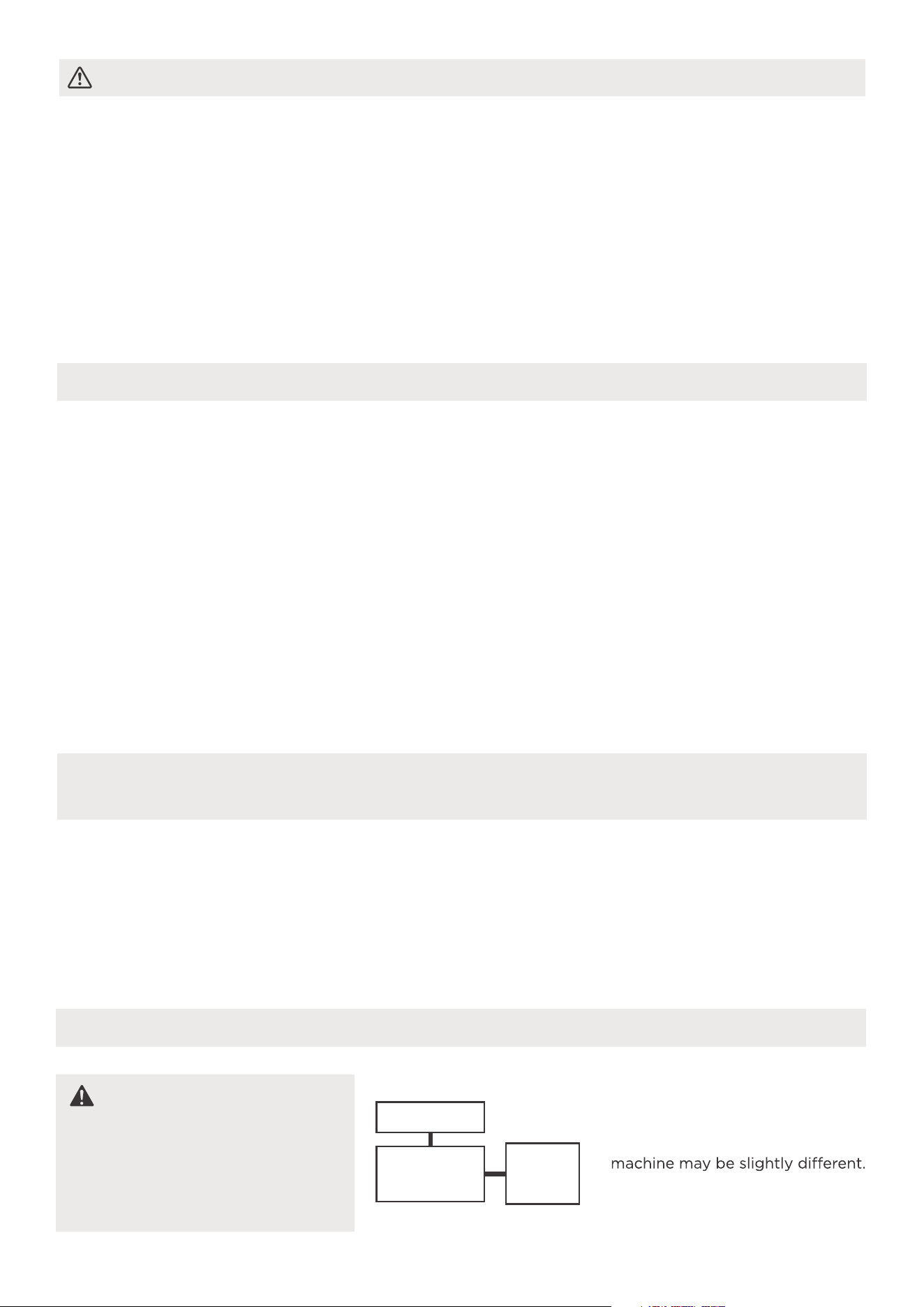
Electronic Work
WARNING:
BEFORE PERFORMING
ANY ELECTRICAL OR
WIRING WORK, TURN
OFF THE MAIN POWER
TO THE SYSTEM.
NOTE: The cographs are for
explanation purpose only. Your
The actual shape shall prevail.
DISPLAY
MAIN
CONTROL
POWER
SUPPLY
CORD
•
Do not use means to accelerate the defrosting process or to clean, other than those
recommended by the manufacturer.
•
The appliance shall be stored in a room without continuously operating ignition
sources (for example: open flames, an operating gas appliance or an operating
electric heater).
•
Do not pierce or burn.
•
Be aware that the refrigerants may not contain an odour.
•
Appliance should be installed, operated and stored in a room with a floor area
according to the amount of refrigerant to be charged. For specific information on
the type of gas and the amount, please refer to the relevant label on the unit itself.
•
Appliance should be installed, operated and stored in a room with a floor area
larger than 4 m
2
.
•
Compliance with national gas regulations shall be observed.
Keep ventilation openings clear of obstruction.
•
The appliance shall be stored so as to prevent mechanical damage from occurring.
•
A warning that the appliance shall be stored in a well-ventilated area where the
room size corresponds to the room area as specified for operation.
•
Any person who is involved with working on or breaking into a refrigerant circuit
should hold a current valid certificate from an industry-accredited assessment
authority, which authorises their competence to handle refrigerants safely in
accordance with an industry recognised assessment specification.
•
Servicing shall only be performed as recommended by the equipment manufacturer.
Maintenance and repair requiring the assistance of other skilled personnel shall be
carried out under the supervision of the person competent in the use of flammable
refrigerants.
•
The appliance shall be stored in a room without continuously operating open flames
(for example an operating gas appliance) and ignition sources (for example an
operating electric heater).
WARNING for Using R32/R290 Refrigerant
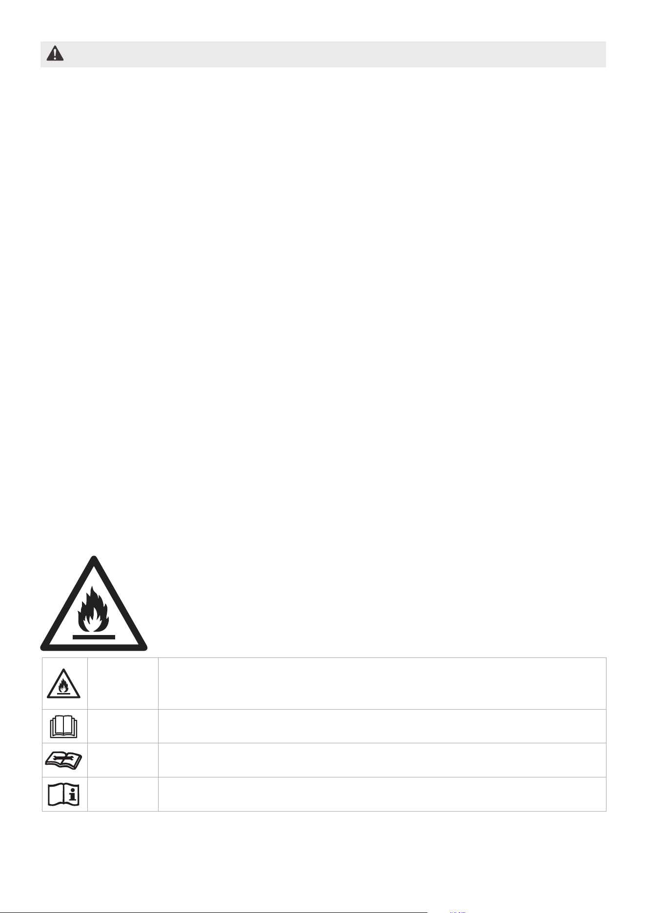
05
Caution:
Risk of fire/flammable materials
Explanation of symbols displayed on the unit(For the unit adopts
R32/R290 Refrigerant only):
WARNING
CAUTION
CAUTION
CAUTION
This symbol shows that this appliance used a flammable refrige-rant.
If the refrigerant is leaked and exposed to an external ignition source,
there is a risk of fire.
This symbol shows that the operation manual should be read carefully.
This symbol shows that a service personnel should be handling this
equipment with reference to the installation manual.
This symbol shows that information is available such as the operating
manual or installation manual.

06
1. Transport of equipment containing flammable refrigerants
See transport regulations
2.Marking of equipment using signs
See local regulations
3.Disposal of equipment using flammable refrigerants
See national regulations.
4.Storage of equipment/appliances
The storage of equipment should be in accordance with the manufacturer's
instructions.
5.Storage of packed (unsold) equipment
Storage package protection should be constructed such that mechanical damage to
the equipment inside the package will not cause a leak of the refrigerant charge.
The maximum number of pieces of equipment permitted to be stored together will
be determined by local regulations.
6.Information on servicing
1)Checks to the area
Prior to beginning work on systems containing flammable refrigerants, safety
checks are necessary to ensure that the risk of ignition is minimised. For repair to
the refrigerating system, the following precautions shall be complied with prior to
conducting work on the system.
2)Work procedure
Work shall be undertaken under a controlled procedure so as to minimise the risk
of a flammable gas or vapour being present while the work is being performed.
3)General work area
All maintenance staff and others working in the local area shall be instructed on
the nature of work being carried out. Work in confined spaces shall be avoided.
The area around the workspace shall be sectioned off. Ensure that the conditions
within the area have been made safe by control of flammable material.
4)Checking for presence of refrigerant
The area shall be checked with an appropriate refrigerant detector prior to and
during work, to ensure the technician is aware of potentially flammable
atmospheres. Ensure that the leak detection equipment being used is suitable for
use with flammable refrigerants, i.e. non-sparking, adequately sealed or intrinsically
safe.
5)Presence of fire extinguisher
If any hot work is to be conducted on the refrigeration equipment or any
associated parts, appropriate fire extinguishing equipment shall be available to
hand. Have a dry powder or CO2 fire extinguisher adjacent to the charging area.
6)No ignition sources
No person carrying out work in relation to a refrigeration system which involves
exposing any pipe work that contains or has contained flammable refrigerant shall
use any sources of ignition in such a manner that it may lead to the risk of fire or
explosion. All possible ignition sources, including cigarette smoking, should be kept
sufficiently far away from the site of installation, repairing, removing and disposal,
during which flammable refrigerant can possibly be released to the surrounding
space. Prior to work taking place, the area around the equipment is to be surveyed
to make sure that there are no flammable hazards or ignition risks. No Smoking
signs shall be displayed.
7)Ventilated area
Ensure that the area is in the open or that it is adequately ventilated before
breaking into the system or conducting any hot work. A degree of ventilation shall
continue during the period that the work is carried out. The ventilation should
safely disperse any released refrigerant and preferably expel it externally into
the atmosphere.

8)Checks to the refrigeration equipment
Where electrical components are being changed, they shall be fit for the purpose
and to the correct specification. At all times the manufacturer's maintenance and
service guidelines shall be followed. If in doubt consult the manufacturer's
technical department for assistance. The following checks shall be applied to
installations using flammable refrigerants:
The charge size is in accordance with the room size within which the refrigerant
containing parts are installed;
The ventilation machinery and outlets are operating adequately and are not
obstructed;
If an indirect refrigerating circuit is being used, the secondary circuit shall be
checked for the presence of refrigerant; Marking to the equipment continues to be
visible and legible. Markings and signs that are illegible shall be corrected;
Refrigeration pipe or components are installed in a position where they are unlikely
to be exposed to any substance which may corrode refrigerant containing
components, unless the components are constructed of materials which are
inherently resistant to being corroded or are suitably protected against being so
corroded.
9)Checks to electrical devices
Repair and maintenance to electrical components shall include initial safety checks
and component inspection procedures. If a fault exists that could compromise
safety, then no electrical supply shall be connected to the circuit until it is
satisfactorily dealt with. If the fault cannot be corrected immediately but it is
necessary to continue operation, an adequate temporary solution shall be used.
This shall be reported to the owner of the equipment so all parties are advised.
Initial safety checks shall include:
That capacitors are discharged: this shall be done in a safe manner to avoid
possibility of sparking;
That there no live electrical components and wiring are exposed while charging,
recovering or purging the system; That there is continuity of earth bonding.
7.Repairs to sealed components
1)During repairs to sealed components, all electrical supplies shall be disconnected
from the equipment being worked upon prior to any removal of sealed covers, etc.
If it is absolutely necessary to have an electrical supply to equipment during
servicing, then a permanently operating form of leak detection shall be located at
the most critical point to warn of a potentially hazardous situation.
2)Particular attention shall be paid to the following to ensure that by working on
electrical components, the casing is not altered in such a way that the level of
protection is affected. This shall include damage to cables, excessive number of
connections, terminals not made to original specification, damage to seals,
incorrect fitting of glands, etc. Ensure that apparatus is mounted securely. Ensure
that seals or sealing materials have not degraded such that they no longer serve
the purpose of preventing the ingress of flammable atmospheres. Replacement
parts shall be in accordance with the manufacturer's specifications.
NOTE: The use of silicon sealant may inhibit the effectiveness of some types of
leak detection equipment. Intrinsically safe components do not have to be isolated
prior to working on them.
8.Repair to intrinsically safe components
Do not apply any permanent inductive or capacitance loads to the circuit without e
nsuring that this will not exceed the permissible voltage and current permitted for
the equipment in use. Intrinsically safe components are the only types that can be
worked on while live in the presence of a flammable atmosphere. The test apparatus
shall be at the correct rating. Replace components only with parts specified by the
manufacturer. Other parts may result in the ignition of refrigerant in the atmosphere
from a leak.
07

9.Cabling
Check that cabling will not be subject to wear, corrosion, excessive pressure,
vibration, sharp edges or any other adverse environmental effects. The check shall
also take into account the effects of aging or continual vibration from sources such
as compressors or fans.
10.Detection of flammable refrigerants
Under no circumstances shall potential sources of ignition be used in the searching
for or detection of refrigerant leaks. A halide torch (or any other detector using a
naked flame) shall not be used.
11.Leak detection methods
The following leak detection methods are deemed acceptable for systems
containing flammable refrigerants. Electronic leak detectors shall be used to detect
flammable refrigerants, but the sensitivity may not be adequate, or may need
re-calibration. (Detection equipment shall be calibrated in a refrigerant-free area.)
Ensure that the detector is not a potential source of ignition and is suitable for the
refrigerant used. Leak detection equipment shall be set at a percentage of the LFL
of the refrigerant and shall be calibrated to the refrigerant employed and the
appropriate percentage of gas (25 % maximum) is confirmed. Leak detection fluids
are suitable for use with most refrigerants but the use of detergents containing
chlorine shall be avoided as the chlorine may react with the refrigerant and corrode
the copper pipe-work. If a leak is suspected, all naked flames shall be removed/
extinguished. If a leakage of refrigerant is found which requires brazing, all of the
refrigerant shall be recovered from the system, or isolated (by means of shut off
valves) in a part of the system remote from the leak.
Oxygen free nitrogen (OFN) shall then be purged through the system both before
and during the brazing process.
12.Removal and evacuation
When breaking into the refrigerant circuit to make repairs or for any other purpose
conventional procedures shall be used. However, it is important that best practice is
followed since flammability is a consideration. The following procedure shall be
adhered to:
Remove refrigerant; Purge the circuit with inert gas; Evacuate; Purge again with
inert gas; Open the circuit by cutting or brazing.
The refrigerant charge shall be recovered into the correct recovery cylinders. The
system shall be flushed with OFN to render the unit safe. This process may need to
be repeated several times. Compressed air or oxygen shall not be used for this task.
Flushing shall be achieved by breaking the vacuum in the system with OFN and
continuing to fill until the working pressure is achieved, then venting to atmosphere,
and finally pulling down to a vacuum. This process shall be repeated until no
refrigerant is within the system.
When the final OFN charge is used, the system shall be vented down to atmospheric
pressure to enable work to take place. This operation is absolutely vital if brazing
operations on the pipe-work are to take place. Ensure that the outlet for the vacuum
pump is not close to any ignition sources and there is ventilation available.
13.Charging procedures
In addition to conventional charging procedures, the following requirements shall
be followed. Ensure that contamination of different refrigerants does not occur
when using charging equipment. Hoses or lines shall be as short as possible to
minimise the amount of refrigerant contained in them.
Cylinders shall be kept upright.
Ensure that the refrigeration system is earthed prior to charging the system with
refrigerant.
Label the system when charging is complete (if not already).
Extreme care shall be taken not to overfill the refrigeration system. Prior to
recharging the system it shall be pressure tested with OFN. The system shall be leak
tested on completion of charging but prior to commissioning. A follow up leak test
shall be carried out prior to leaving the site.
08

14.Decommissioning
Before carrying out this procedure, it is essential that the technician is completely
familiar with the equipment and all its detail. It is recommended good practice that
all refrigerants are recovered safely.
Prior to the task being carried out, an oil and refrigerant sample shall be taken in
case analysis is required prior to re-use of reclaimed refrigerant. It is essential that
electrical power is available before the task is commenced.
a) Become familiar with the equipment and its operation. b) Isolate system
electrically. c) Before attempting the procedure ensure that: Mechanical handling
equipment is available, if required, for handling refrigerant cylinders;All personal
protective equipment is available and being used correctly; The recovery process
is supervised at all times by a competent person; Recovery equipment and
cylinders conform to the appropriate standards. d) Pump down refrigerant system,
if possible. e) If a vacuum is not possible, make a manifold so that refrigerant can
be removed from various parts of the system. f) Make sure that cylinder is
situated on the scales before recovery takes place. g) Start the recovery machine
and operate in accordance with manufacturer's instructions. h) Do not overfill
cylinders. (No more than 80 % volume liquid charge). i) Do not exceed the
maximum working pressure of thecylinder, even temporarily. j) When the
cylinders have been filled correctly and the process completed, make sure that the
cylinders and the equipment are removed from site promptly and all isolation
valves on the equipment are closed off. k) Recovered refrigerant shall not be
charged into another refrigeration system unless it has been cleaned and checked.
15.Labelling
Equipment shall be labelled stating that it has been de-commissioned and emptied
of refrigerant. The label shall be dated and signed. Ensure that there are labels on
the equipment stating the equipment contains flammable refrigerant.
16.Recovery
When removing refrigerant from a system, either for servicing or decommissioning,
it is recommended good practice that all refrigerants are removed safely. When
transferring refrigerant into cylinders, ensure that only appropriate refrigerant
recovery cylinders are employed. Ensure that the correct number of cylinders for
holding the total system charge is available. All cylinders to be used are designated
for the recovered refrigerant and labelled for that refrigerant (i.e. special cylinders
for the recovery of refrigerant). Cylinders shall be complete with pressure relief
valve and associated shut-off valves in good working order. Empty recovery
cylinders are evacuated and, if possible, cooled before recovery occurs. The
recovery equipment shall be in good working order with a set of instructions
concerning the equipment that is at hand and shall be suitable for the recovery of
flammable refrigerants. In addition, a set of calibrated weighing scales shall be
available and in good working order. Hoses shall be complete with leak-free
disconnect couplings and in good condition. Before using the recovery machine,
check that it is in satisfactory working order, has been properly maintained and
that any associated electrical components are sealed to prevent ignition in the
event of a refrigerant release. Consult manufacturer if in doubt. The recovered
refrigerant shall be returned to the refrigerant supplier in the correct recovery
cylinder, and the relevant Waste Transfer Note arranged. Do not mix refrigerants
in recovery units and especially not in cylinders. If compressors or compressor oils
are to be removed, ensure that they have been evacuated to an acceptable level to
make certain that flammable refrigerant does not remain within the lubricant. The
evacuation process shall be carried out prior to returning the compressor to the
suppliers. Only electric heating to the compressor body shall be employed to
accelerate this process. When oil is drained from a system, it shall be carried out
safely.
09

10
SPECIFICATIONS
MDDQ1-12DEN7-QA3
Product Model
Power source
Capacity (DB=30 RH=80%)
Rated current
Rated power input
Resistance class
12 L/DAY
2.1A
380W
220-240V~ 50Hz, 1Ph
IPX0
11
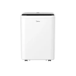
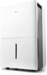
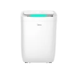
NOTE ON ILLUSTRATIONS:
PRODUCT OVERVIEW
All the illustrations in the manual are for explanation purpose only. Your machine may be slightly
different. The actual shape shall prevail. The unit can be controlled by the unit control panel alone or
with the remote controller. This manual does not include Remote Controller Operations, see the
<<Remote Controller Instruction>> packed with the unit for details.
Model A(1)
Model A(2)
NOTE
In order to ensure the optimal performance of our products, the design specifications of the unit are
subject to change without prior notice.
caster(on some models)
drain hose outlet
air intake grille
power cord and plug
water level window
rear
control panel
air outlet grille
guick glance light
water bucket
handle
front
drain hose outlet
air intake grille
power cord and plug
water level window
rear
control panel
air outlet grille
guick glance light
water bucket
handle
front
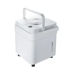
A dehumidifier operating in a basement will have little or no effect in drying an adjacent enclosed
storage area, such as a closet, unless there is adequate circulation of air in and out of the area.
• Do not use outdoors.
• This dehumidifer is intended for indoor residential applications only. This dehumidifer should not be
used for commercial or industrial applications.
• Place the dehumidifier on a smooth, level floor strong enough to support the unit with a full bucket
of water.
• Allow at least 20cm of air space on all sides of the unit for good air circulation (at least 40cm of air
space on air outlet).
• Place the unit in an area where the temperature will not fall below 5 °C(41 °F). The coils can become
covered with frost at temperatures below 5 °C(41 °F), which may reduce performance.
• Place the unit away from the clothes dryer, heater or radiator.
• Use the unit to prevent moisture damage anywhere books or valuables are stored.
• Use the dehumidifier in a basement to help prevent moisture damage.
• The dehumidifier must be operated in an enclosed area to be most effective.
• Close all doors, windows and other outside openings to the room.
• When first using the dehumidifier in Continuous
dehumidifying mode, make sure the connection
of the water hose and the drain hose outlet of
the unit is tight and do not let the water leak.
• This unit is designed to operate with a working
environment between 5 °C/41 °F and
32 °C/90 °F, and between 30%(RH) and
80%(RH)
• If the unit has been switched off and needs to
be switched on again quickly , allow
approximately three minutes for the correct
operation to resume.
• Do not connect the dehumidifier to a multiple
socket outlet, which is also being used for
other electrical appliances.
• Select a suitable location, making sure you have
easy access to an electrical outlet.
• Plug the unit into a electrical socket-outlet with
earth connection.
• Make sure the Water bucket is correctly fitted
other-wise the unit will not operate properly.
12
CONFIRM IT BEFORE YOU GET START
20cm
or more
20cm
or more
Front view Top view
40cm
or more
40cm
or more
40cm
or more
Casters(At four points on the bottom of unit)
Casters can move freely.
Do not force casters to move over carpet, nor move the unit with water in the bucket.
(The unit may tip over and spill water.)
When using the unit
Note: When the water in the bucket reaches to a
certain level, please be careful to move the machine
to avoid it falling down.
• When the bucket is full, the unit will automati-cally stop running, and the Full indicator light will flash.
• Slowly pull out the bucket. Grip the left and right handles securely , and carefully pull out straight so
water does not spill. Do not put the bucket on the floor because the bottom of the bucket is uneven.
Otherwise the bucket will fall and cause the water to spill.
• Throw away the water from the water outlet and replace the bucket. The bucket must be in place and
securely seated for the dehumid-ifier to operate.The machine will re-start when the bucket is restored
in its correct position.
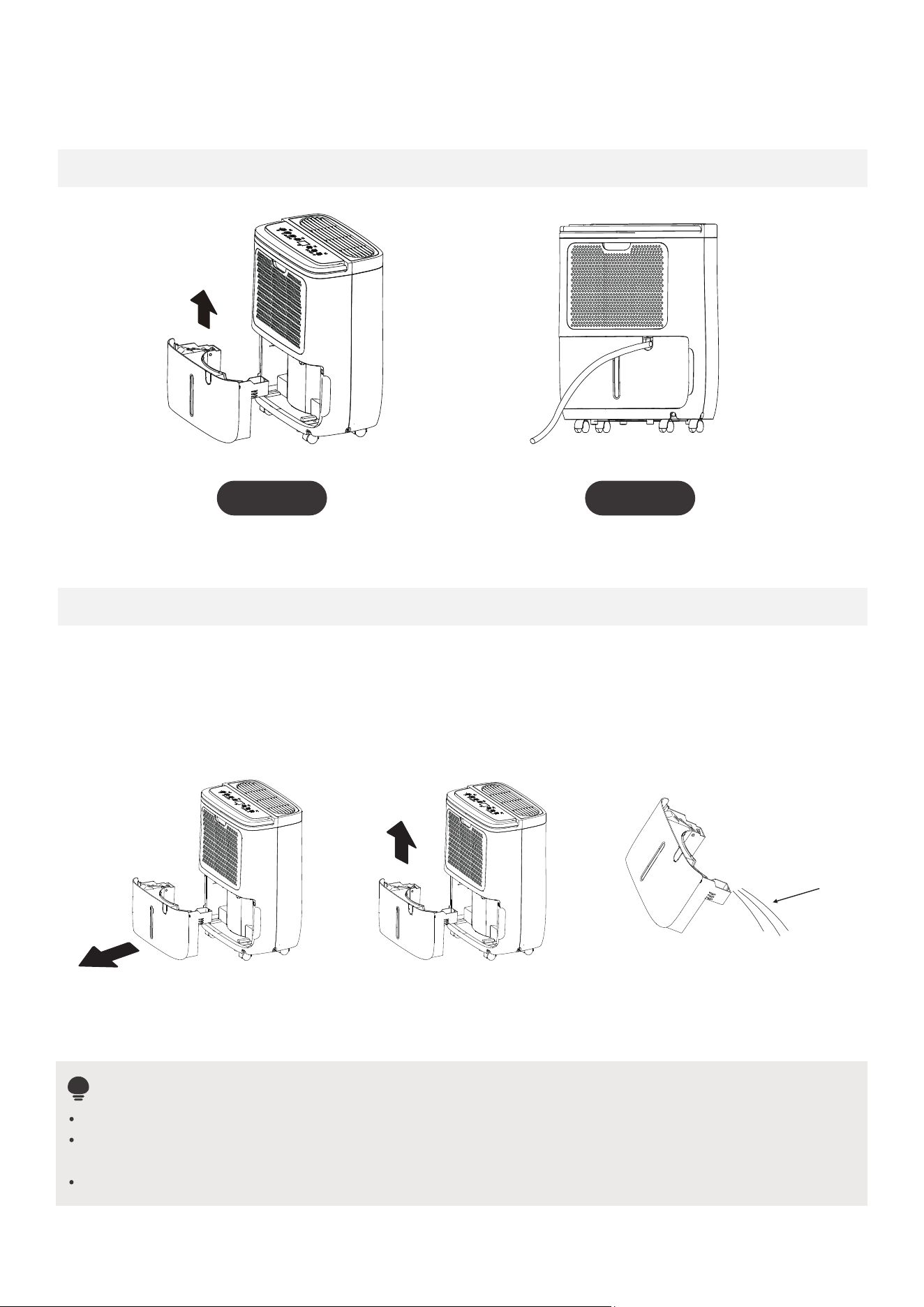
REMOVING THE COLLECTED WATER
There are two ways to remove collected water.
Bucket drainage
Type 1: Type 2:
water hose drainage
(continuous)
Type 1: Use the bucket
Step 1 :
Pull out the bucket
a little.
Step 2 :
Hold both sides of the
bucket with even strength,
and pull it out from the unit.
Step 3 :
Pour the water out.(The bucket
of the unit you purchased may be
slightly different)
NOTE
When you remove the bucket, do not touch anyparts inside of the unit. Doing so may damage the product.
Be sure to push the bucket gently all the way into the unit. Banging the bucket against anything or failing
to push it in securely may cause the unit not to operate.
When you remove the bucket, if there is some water in the unit you must dry it.
13
Water outlet
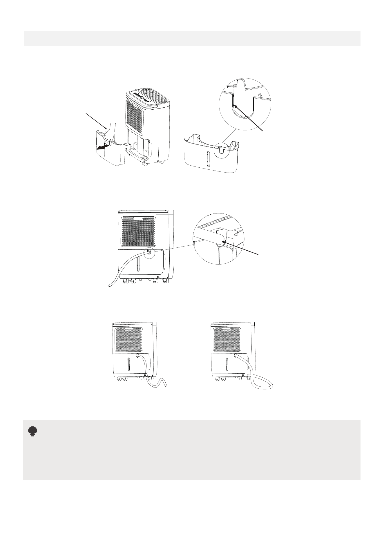
Type 2: water hose drainage (continuous)
NOTE
14
Water can be automatically emptied into a floor drainby attaching the unit with a water hose(Φ16.5*13.5
mm)(not included).
• Remove the plastic konck-out panel from the upper side of the bucket.
Remove the
konck-out panel
Remove all burrs from
the cut section of the
panel.
• Insert the water hose into the unit from the drain outlet in the back of the unit.
• Attach the water hose to the drain hose outlet of the unit.
• Make sure the connection of the water hose and the drain hose outlet of the unit is tight and do not let the
water leak.
Insert the water
hose from the
drain outlet
• Then lead the water hose to the floor drain or a suitable drainage facility .The drainage facilify should be
lower than the drain outlet of the unit. Be sure to run the water hose sloping downward and let the water to
flow out smoothly . Do not install the water hose.
Do not block water flow by a rise.
Do not block water flow by a retortion.
• Make sure the water hose is lower than the drain hose outlet.
• When the continuous drain feature is not being used,remove the drain hose from the outlet.
• Use needle nose pliers if the plastic panel is too difficult to remove by hand.
• Burrs may hurt hand while connecting the drain hose. Please using a reamer or a deburring tool to
remove all burrs from the cut section of the panel.
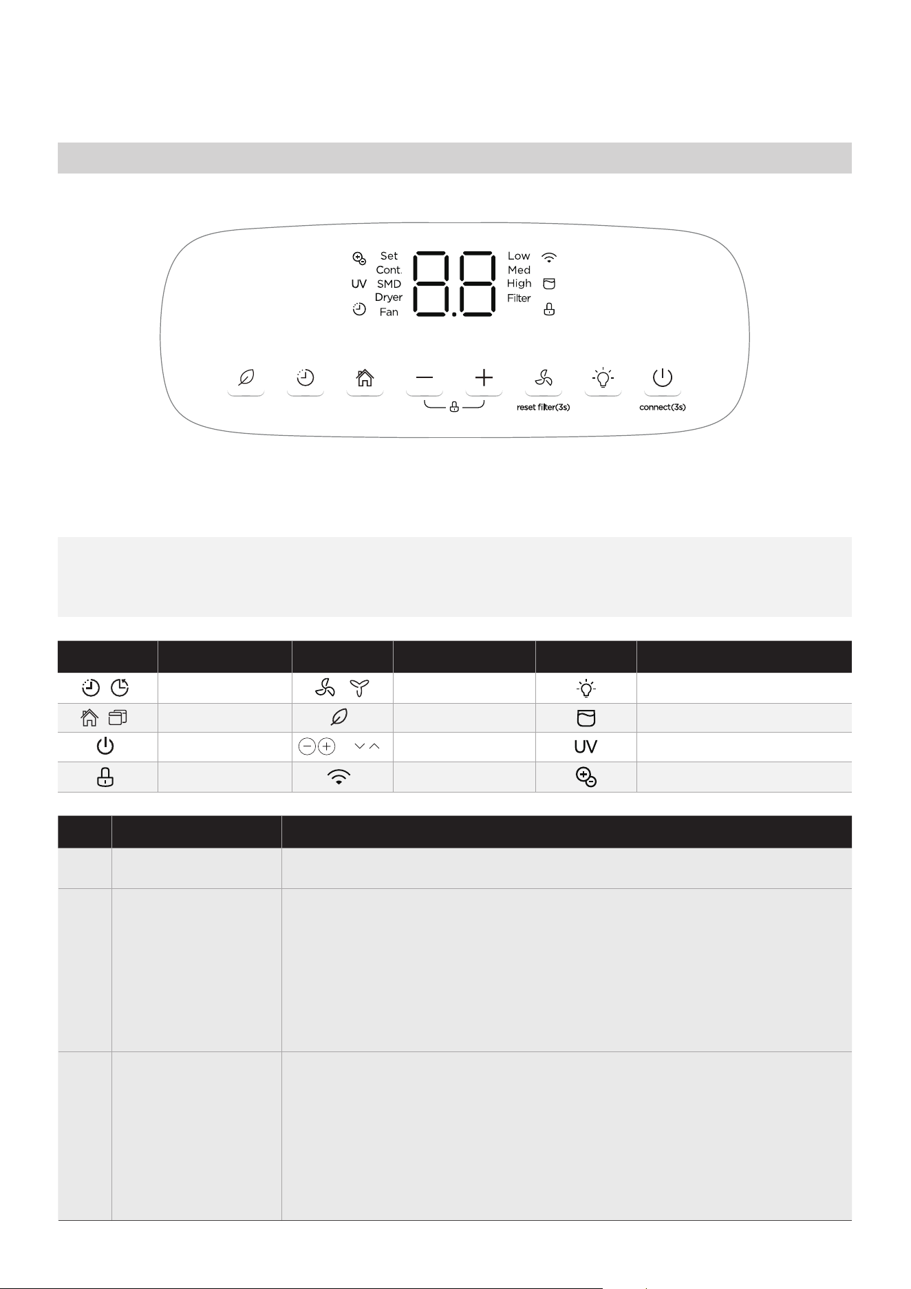
Control Panel
OPERATION INSTRUCTIONS
NOTE: The following control panels are for explanation purpose only. The control panel of the unit
you purchased may be slightly different according to the models. Your machine may not contain some
indicators or buttons. The actual shape shall prevail.
Indicator Function
Indicator
Function Function
Indicator
15
Fan speed button
Lock light
Power button
Timer button / light
Mode button
Fresh button
UP and Down button
/
Water full light
UV light
Fresh light
Wireless light
Quick glance light button
/
/
/
Description
1
2
POWER ON/OFF
MODE - Function
3
Press to select the desired operation mode from Setting dehumidifying,
Dryer model, Smart dehumidifying, Con-tinuous dehumidifying and Fan
mode(on some models).
Press to turn the dehumidifier on and off.
In Setting dehumidifying mode, the set indicator light illuminates.
NOTE: In Continuous dehumidifying, Dryer and Smart dehumidifying
modes, the humidity setting can‘t be adjusted.
In Fan mode the unit do not dehumidify.
Humidity Set Control buttons
TIMER Set Control buttons
Use the Up/Down buttons to set the Auto start and Auto stop time from
0.0 to 24.
The humidity level can be set within a range of 35% RH(Relative Humidity)
to 85%RH(Relative Humidity) in 5% increments. For drier air , press the -
button and set to a lower percent value(%). For damper air, press the +
button and set a higher percent value(%).
UP and DOWN
- Buttons
Description
5
6
FAN - Function
7
4
TIMER - Function
8
9
16
• Press to initiate the Auto start or Auto stop feature, in conjuction with
the + and - buttons. When the unit is on, press the Timer button to
activate the Auto buttons. stop feature. When the unit is off, press this
button to activate the Auto start feature.
• Control the fan speed.Press to select fan speed in three steps-low, med
and high.The fan speed indicator light illuminates under different fan
speed settings.
• Press and hold on the POWER button for 3 seconds to initiate the
Wireless connection mode. The LED DISPLAY shows’AP’ to indicate you
can set Wireless connection.
• Press and hold on the Up and Down buttons for 3 seconds to initiate
LOCK feature, and the Lock Press and hold on the Up and Down buttons
for 3 seconds to initiate LOCK feature, and the Lock
• Press buttons to illuminate the quick glance light or turn quick glance
light dark.
• When the humidity is more than 65%, the quick glance light will emit
red light.
• When the humidity range is at 45% to 65%, the quick glance light will
emit green light.
• When the humidity is lower than 45%, the quick glance light will emit
yellow light.
• Press and hold on the Up and Down buttons for 3 seconds to initiate
LOCK feature, and the Lock
• If connection (router) is successful within 8 minutes, the unit will exit
Wireless connection mode automa-tically and the Wireless indicator
illuminates and the unit enters the previous function. If connection is
failure within 8 minutes, the unit exits the Wireless connection mode
automatically.
• Press and hold the Fan speed button for 3 seconds to eliminate filter
reminder, when the filter light flickers(On some models).
• Press or hold the + and - button to change the Auto time by 0.5 hour
increments, up to 10 hours, then at 1 hour increments up to 24 hours.
• The control will count down the time remaining until start.
• The selected time will register in 5 seconds and the system will
automatically revert back to display the previous humidity setting.
• Turning the unit ON or OFF at any time or adjusting the timer setting
to 0.0 will cancel the Auto start or Auto stop feature.
• When LED display window displays the code of P2, the Auto start or
Auto stop feature will also be cancelled.
NOTE: The unit operates for 250 hours, then enter filter clean reminder.
Wireless - Function
(On some models)
FRESH - Function
(On some models)
LOCK - Function
(On some models)
Quick glance light
- Function
(On some models)
NOTE: When the unit is connecting to internet, the quick glance light will
flash white light.
Press FRESH buttons to initiate FRESH feature, and the fresh indicator
light illuminates(The fresh indicator light and the UV indicator light
illuminate at the same time on some models; Only the UV indicator light
illuminate on some models ).The ion generatoris energized and UV
(UltraViolet) feature will help to purify the air inside.Press FRESH buttons
again to stop FRESH feature, and the fresh indicator light turns dark.
NOTE: When bucket full or clean filter is on, the quick glance light will
emit orange light and turn off 1sec every 4 sec.

Other features
Auto-Restart
Setting dehumidifying mode
Continuous dehumidifying mode
Smart dehumidifying mode
17
Description
10
DISPLAY
(On some models)
Error Codes:
EH60-Humidity sensor error--Unplug the unit and plug it back in. If error
repeats, call for service;
EH61-Tube Temperature sensor of the evaporator error-- Unplug the unit
and plug it back in. If error repeats, call for service;
EH02-Zero-crossing signal detection error; If error repeats, call for service;
EH03-Indoor fan speed malfunction; If error repeats, call for service;
EH0b-Indoor PCB and display board communicationerror; If error repeats,
call for service;
Protection Code:
P2-Bucket is full or bucket is not in right position-- Empty the bucket and
replace it in the right position. On some models, the water full light
illuminates.
NOTE: When one of the above malfunctions occurs, turn off the unit,
and check for any obstructions. Restart the unit, if the malfunction is still
present, turn off the unit and unplug the power cord. Contact the
manufacturer or its service agents or a similar qualified person for service.
Wait 3 minutes before resuming operation
After the unit has stopped, it can not be restart
operation in the first 3 minutes.This is to protect
the unit. Operation will automatically start after
3 minutes.
Bucket Full Light
Glows when the bucket is ready to be emptied, or
when the bucket is removed or not replaced in the
proper position.
Auto Defrost
Auto Shut Off
When forst builds up on the evaporator coils, the
compressor will cycle off and the fan will continue
to run until the frost disappears.
The dehumidifier shuts off when the bucket is full,
or when the bucket is removed or not replaced in
the proper position.
For some models, the fan motor will continue to
run for 30 seconds.
UV Light
For some models, the UV feature will help to purify
the air inside.
Fresh Light
For some models, the ion generatoris energized and
will help to purify the air inside.
If the unit breaks off unexpectedly due to the
power cut, it will restart with the previous
function setting automatically when the power
resumes
At continuous dehumidifying mode, the unit dehumidify
continuously and cannot select humidity. Press mode
button to exit continuous dehumidifying mode.
At smart dehumidifying mode, the unit will automatically
control room humidity in a comfortable range 45%~55%
according to the room temper-ature.The humidity setting
function will be invalid.
At setting dehumidifying mode, the unit can be adjusted
in arange 35%~85%, and the humidity setting can be
adjusted(increase/decreasing) in 5%. Press MODE button
to exit setting dehumidifying mode.
FILTER Light
The check filter feature is a reminder to clean the Air
Filter for more efficient operation. The Filter light will
flicker after 250 hours of operation.
To reset after cleaning the filter , press the Fan button
for 3 seconds and the light will go off.
• Shows the set % humidity level from 35% to 85% or auto start/stop time
(0~24) while setting, then shows the actual(±5% accuracy) room %
humidity level in a range of 30% RH(Relative Humidity) to 90%RH
(Relative Humidity).
Other features
HEPA filterDryer mode(On some models)
The unit can make the MAX dehumidification fun-
ction when it is under Dryer mode. The fan speed
can’t be adjusted.
NOTE:
1. The Dryer(model dependent) mode must be
operated in a close room,do not open the door
and window.
2. To make the best effective dehumidification,
please first dehydrate the wet clothes.
3. Make sure to direct airflow at the wet clothes.
4. For thick and heavy wetclothes may not get
the best effective dehumidification.
30~50cm
Wet clothes
30~50cm
Airflow
Allow 30~50cm
of distance on
the top and right
side of the unit to
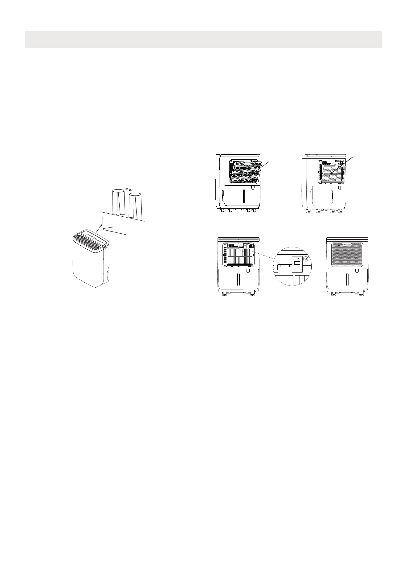
the wet clothes.
• Install the HEPA(High Efficiency Particulate Air)
to reduce the dust and allergen content in the
room.
It may result in insufficient dehumidfying capacity
due to the decreaseing of air intake. To restore the
normal dehumidfying operation, just take down
the HEPA filter.
• Make sure you have fitted the HEPA filter as
indicated in fig1-4.
HEPA filter
filter
Fig2. Insert the lower side of the
HEAP filter into the unit.
Fig1.Remove the filter
Fig3.Clip the upper side as shown. Fig4.Install the filter
18
CLEANING AND MAINTENANCE
Clean the Grille and Case
Use water and a mild detergent. Do not use bleach or abrasives.
Do not splash water directly onto the main unit. Doing so may cause an electrical shock, cause the
insulation to deteriorate, or cause the unit to rust.
The air intake and outlet grilles get soiled easily, so use a vacuum attachment or brush to clean.
wall outlet before cleaning.
Every few weeks, clean the bucket to prevent growth of mold, mildew and bacteria. Partially fill the bucket
with clean water and add a little mild detergent. Swish it around in the bucket, empty and rinse.
Note: Do not use a dishwasher to clean the bucket. After clean, the bucket must be in place and securely
seated for the dehumidifier to operate.
Clean the bucket
Clean the air filter
19
NOTE: The cabinet and front may be dusted with an oil-free cloth or washed with a cloth
dampened in a solution of warm water and mildliquid dishwashing detergent. Rinse
thoroughly and wipe dry. Never use harsh cleansers, wax or polish on the cabinet front.
Be sure to wring excess water from the cloth before wiping around the controls. Excess
water in or around the controls may cause damage to the unit.
The air filter behind the front grille should be checked and cleaned at least every two weeks or
more often if necessary.
NOTE: DO NOT RINSE OR PUT THE FILTER IN AN AUTOMATIC DISHWASHER.
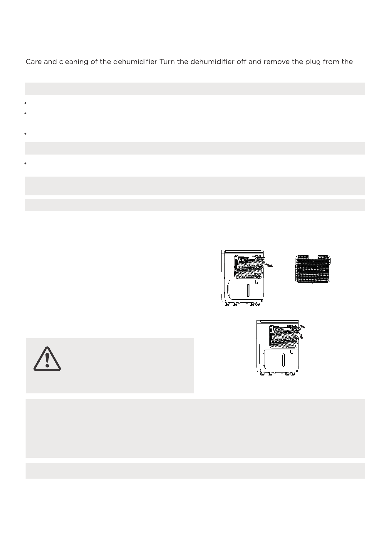
To remove:
•
Grip the tab on the filter and pull it outward,
then pull it up.
•
Clean the filter with warm, soapy water. Rinse
and let the filter dry before replacing it. Do not
clean the filter in a dishwasher.
To attach:
•
Insert the air filter into the unit from underside
to upside.
CAUTION
DO NOT operate the
dehumidifier without a filter
because dirt and lint will clog
it and reduce performance.
When not using the unit for long time periods
•
Clean the main unit, water bucket and air filter.
•
After turning off the unit, wait one day before emptying the bucket.
•
Cover the unit with a plastic bag.
•
Store the unit upright in a dry, well-ventilated place.
20
TROUBLESHOOTING
Problem What to check
Unit does not start
Make sure the dehumidifiers plug is pushed completely into the outlet.
Check the house fuse/circuit breaker box.
Dehumidifier has reached its preset level or bucket is full.
Water bucket is not in the proper position.
The air filter is clogged.
The unit is tilted instead of upright as it should be.
The floor surface is not level.
Hose to connector or hose connection may be loose.
Intend to use the bucket to collect water, but the back drain plug
is removed.
This is normal. The dehumidifier has Auto defrost feature.
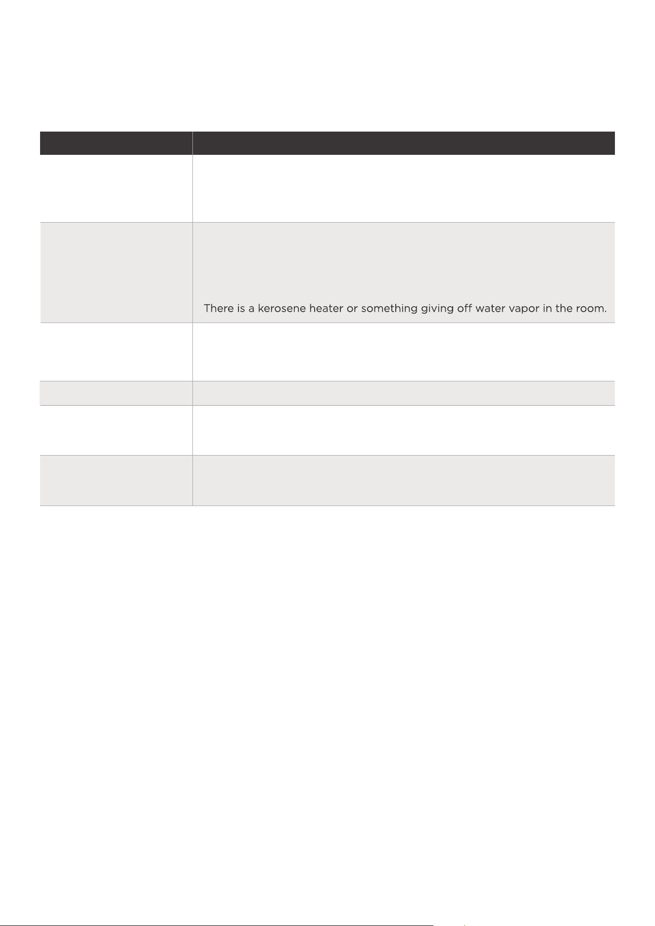
Dehumidifier does not
dry the air as it should
The unit makes a loud
noise when operating
Frost appears on the coils
Water on floor
Before calling for service, review the chart below first yourself.
Did not allow enough time to remove the moisture.
Make sure there are no curtains, blinds or furniture blocking the front or
back of the dehumidifier.
The humidity control may not be set low enough.
Check that all doors, windows and other openings are securely closed.
Room temperature is too low , below 5°C(41°F).
These are error codes and protection codes. See the CONTROL PANEL
FEATURES section.
EH60,EH61,EH02,EH03,
EH0b,P2 appear in the
display
21
DISPOSAL AND RECYCLING
Important instructions for environment(European Disposal Guidelines)
Compliance with the WEEE Directive and Disposing of the Waster Product:
This product complies with EU WEEE Directive. This product bears a classification
symbol for waster electrical and electronic equipment (WEEE).
This symbol indicates that this product shall not be dis-
posed with other household wastes at the end of its ser-
-
tion point for recycling of electrical electronic devices. To
authorities or retailer where the product was purchased.
Each household performs important role in recovering
and recycling of old appliance. Appropriate disposal of
used appliance helps prevent potential negative conse-
quences for the environment and human health.
logo, word marks, trade name, trade dress and all versions thereof are valu-
-
marks, copyrights and other intellectual property rights, and all goodwill derived from
using any part of an Midea trademark. Use of Midea trademark for commercial purposes
without the prior written consent of Midea may constitute trademark
infringement or unfair competition in violation of relevant laws.
This manual is created by Midea and Midea reserves all copyrights thereof. No entity or
individual may use, duplicate, modify, distribute in whole or in part this manual, or
bundle or sell with other products without the prior written consent of Midea.
All the described functions and instructions were up to date at the time of printing this
manual. However, the actual product may vary due to improved functions and designs.
TRADEMARKS, COPYRIGHTS
AND LEGAL STATEMENT
find these collection systems please contact to your local
22
DATA PROTECTION NOTICE
For the provision of the services agreed with the customer,
we agree to comply without restriction with all stipulations of applicable data
protection law, in line with agreed countries within which services to the customer
will be delivered, as well as, where applicable, the EU General Data Protection
Regulation (GDPR).
Generally, our data processing is to fulfil our obligation under contract with you and
for product safety reasons, to safeguard your rights in connection with warranty
and product registration questions. In some cases, but only if appropriate data
protection is ensured, personal data might be transferred to recipients located
outside of the European Economic Area.
Further information are provided on request. You can contact our Data Protection
[email protected]. To exercise your rights such as right to object
your personal date being processed for direct marketing purposes, please contact
us via [email protected]. To find further information, please follow the QR
Code.

The design and specifications are subject to change without prior notice for
product improvement. Consult with the sales agency or manufacturer for details.
Any updates to the manual will be uploaded to the service website, please check
for the latest version.

Thank you for purchasing this midea dehumidifier unit. Should your product prove to be defec�ve
in material or workmanship under normal use within the 1
st
Year of ownership we will replace
the defec�ve part(s) we deem to be faulty, or at our discre�on replace the en�re product.
Our warranty terms are only available to the original purchaser.
To register your equipment for an extended 3 Year Warranty you must complete and return the
sec�on below within 14 days of purchase.
Please send a photo/scan of this page and send by e
mail only to warranty@ uk.co.uk
**You can find the model and serial number on a label on the back or side of your dehumidifier**
Room/Purpose of use:
Address:
Model Number:
Serial Number:
Date of Purchase:
Customer Details:
This data will be held on a computer by our registra�ons department for the provision of warranty
and marke�ng informa�on purposes only. This data will not be disclosed to any third par�es unless
required in the provision of warranty and services on your equipment.
Please �ck the box provided should you wish not to receive marke�ng informa�on for us.
This guarantee does not affect your statutory rights.
midea
WARRANTY CARD
MIDEA
DEHUMIDIFIER
CD001-DQ1
20230427
2023