MAD
MAD50PS1BQGR
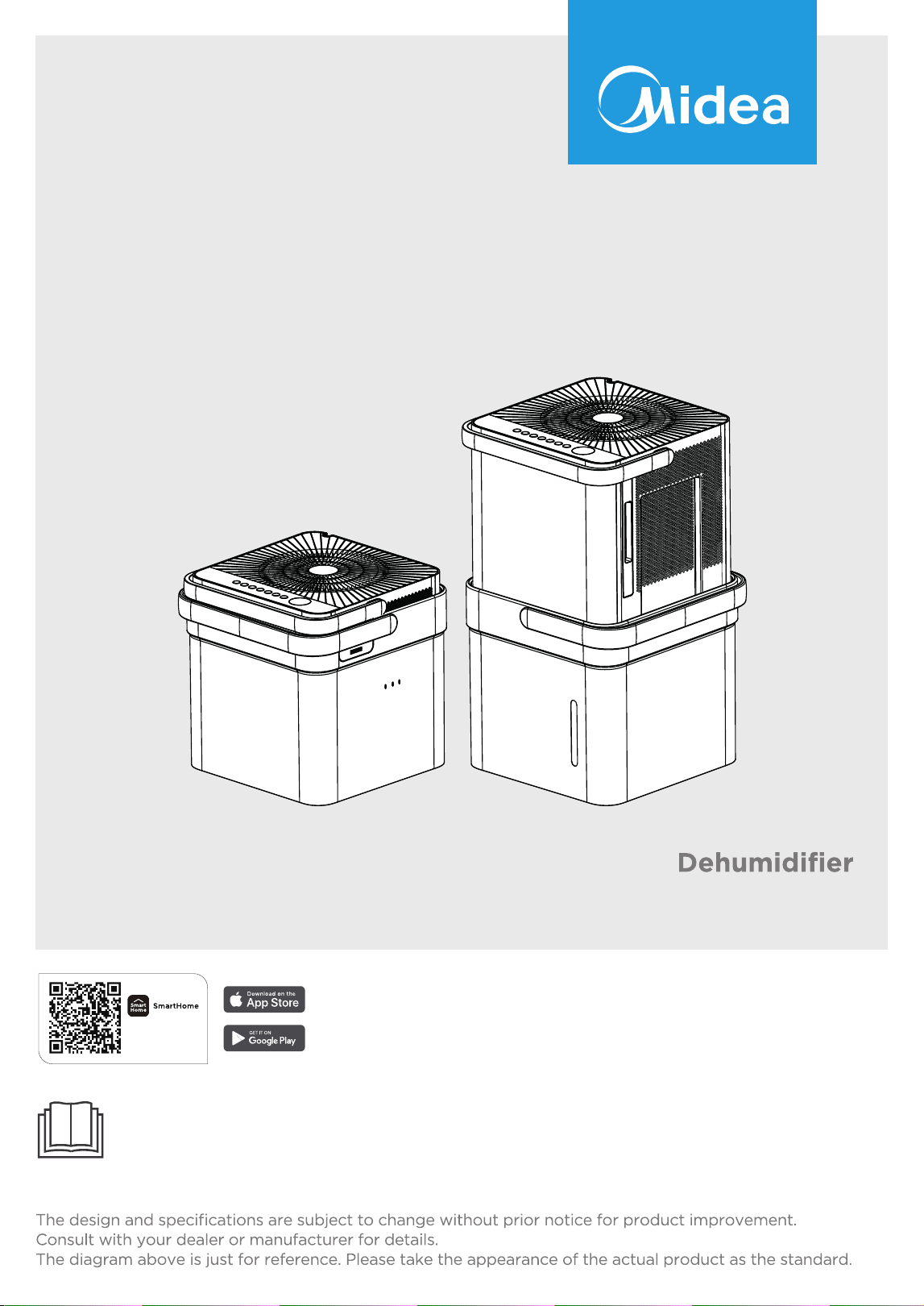
USER MANUAL
Warning notices: Before using this product, please read this manual carefully and keep it for future reference.
Download the app
& activate product

2
CONTENTS
THANK YOU LETTER
Thank you for choosing Midea! Before using your new Midea product, please read this manual
thoroughly to ensure that you know how to operate the features and functions that your new
dehumidifi er offers in a safe way.
THANK YOU LETTER ...............................................................................................................2
SAFETY PRECAUTIONS ...................................................................................................... ..3
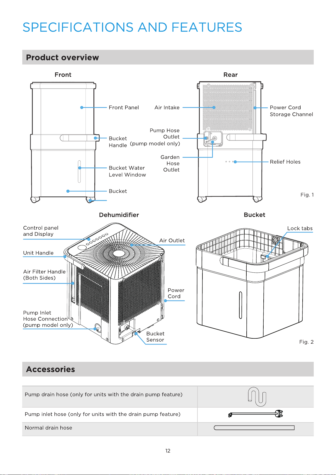
SPECIFICATIONS AND FEATURES ...................................................................................12
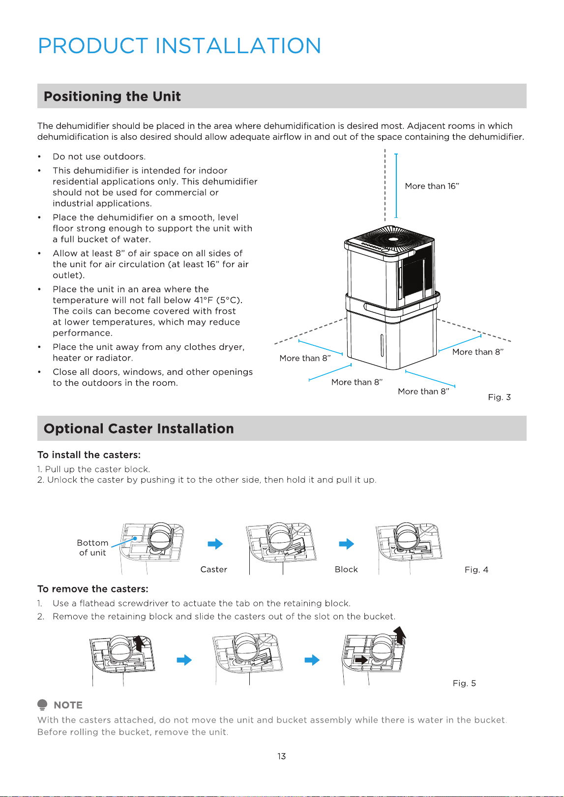
PRODUCT INSTALLATION ....................................................................................................13
OPERATION INSTRUCTIONS ...............................................................................................21
APP INSTRUCTIONS .................................................................................................................24
CLEANING AND MAINTENANCE........................................................................................28
TROUBLESHOOTING TIPS ....................................................................................................30
WARRANTY ................................................................................................................................31
3
SAFETY PRECAUTIONS
Explanation of Symbols
Read these operating instructions carefully and attentively before using/commissioning the unit and keep them
Warning
The signal word indicates a hazard with a medium level of risk which, if
not avoided, may result in death or serious injury.
Always do this
This signal means that the operation can be performed.
Caution
The signal word indicates a hazard with a low degree of risk which, if not
avoided, may result in minor or moderate injury.
Never do this
This signal indicates the prompt operation is prohibited., if not avoided,
may result in Product damaged or injury.
Read Safety Precautions Before Operation and Installation To prevent death or injury to the user or other people
and property damage, the following instructions must be followed. Incorrect operation due to ignoring of
instructions may cause death, harm or damage.
4
WARNING
CAUTION
Do not exceed the rating of the power outlet or connection device.
Do not operate or stop the unit by switching on or off the power.
Do not damage or use an unspecified power cord.
Do not modify power cord length or share the outlet with other appliances. Do not
insert or pull out plug with wet hands.
Do not install the appliance in a location that may be exposed to combustible gas.
Do not place the unit near a heat source.
Disconnect the power if strange sounds, smell, or smoke comes from it. You should
never try to take apart or repair the unit by yourself.
Before cleaning, turn off the power and unplug the unit.
Do not use the machine near flammable gas or combustibles, such as gasoline, ben-
zene, thinner, etc.
Do not drink or use the water drained from the unit.
Do not take the water bucket out during operation.
Do not use the unit in small spaces.
Do not put in places where water may splash onto the unit.
Place the unit on a level, sturdy section of the floor.
Do not cover the intake or exhaust openings with cloths or towels. Care should be
taken when using the unit in a room with the following persons: infants, children, elderly
people,and people not senstive to humidity.
Do not use in areas where chemicals are handled.
Never insert your finger or other foreign objects into grills or openings. Take special
care to warn children of these dangers.
Do not place heavy object on the power cord and take care so that the cord is not
compressed.
Do not climb up on or sit on the unit.
Always insert the filters securely. Clean filter once every two weeks. If water enters the
unit, turn the unit off and disconnect the power , contact a qualified service technician.
Do not place flower vases or other water container on top of
the unit.
Do not use extension cords.
This appliance is not intended for use by persons (including childern) with reduced
physical, sensory or mental capabilities or lack of experience and knowledge, unless
they have been given supervision or instruction concerning use of the appliance by a
person responsible for their safety. Children should be supervised to ensure that they
do not play with the appliance.
If the supply cord is damaged, it must be replaced by the manufacturer, its service
agent or similarly qualified persons in order to avoid a hazard. Prior to cleaning or other
maintenance, the appliance must be disconnected from the supply mains.
Do not install the appliance in a location that may be exposed to combustible gas. If
combustible gas accumulates around the unit, it may cause fire.
If the appliance is knocked over during use, turn off the unit and unplug it from the
main power supply immediately. Visually inspect the unit to ensure there is no damage.
If you suspect the unit has been damaged, contact a technician or customer service for
assistance.
5
CAUTION
Electronic Work
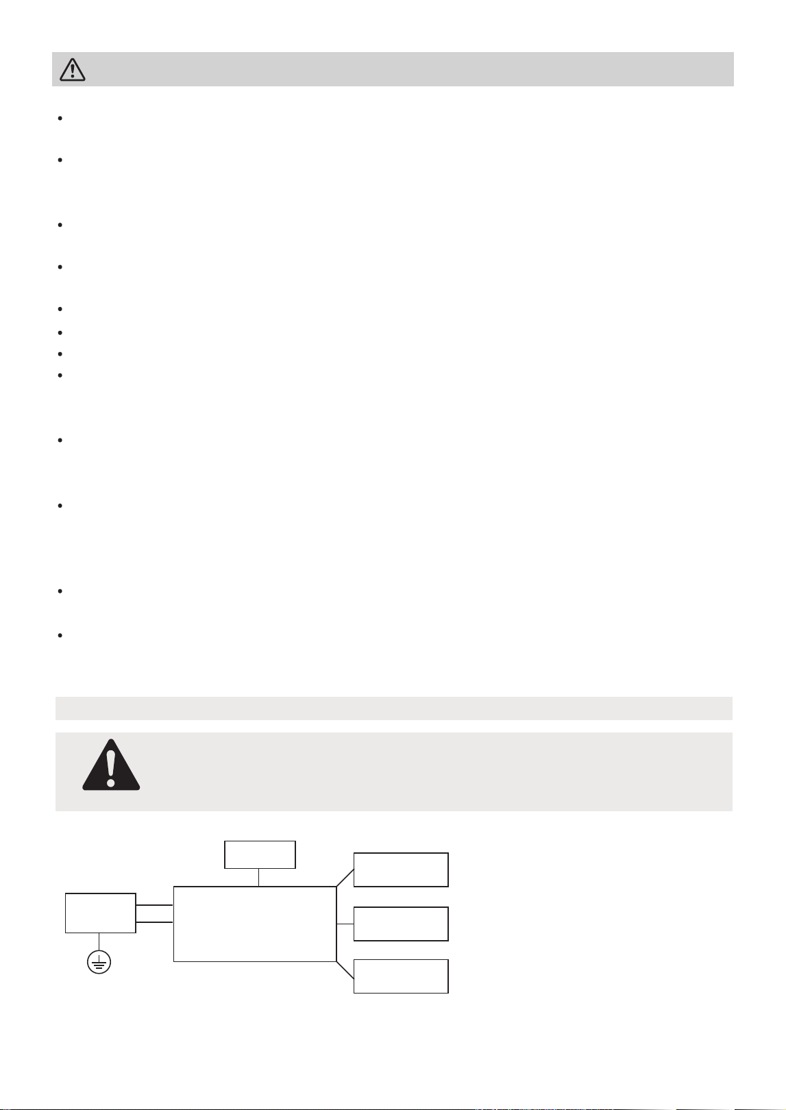
WARNING:
BEFORE PERFORMING ANY ELECTRICAL OR WIRING WORK, TURN OFF THE
MAIN POWER TO THE SYSTEM.
Electronic Type
Main Control
Compressor
Fan Motor
Display
Power
Supply
L/AC L/L1/L-IN
N/AC N/L2/N-IN
Other
In a thunderstorm, the power must be cut off to avoid damage to the machine due to
lightning.
Do not run cord under carpeting. Do not cover cord with throw rugs, runners, or
similar coverings. Do not route cord under furniture or appliances. Arrange cord away
from traffic area and where it will not be tripped over.
Do not operate unit with a damaged cord or plug. Discard unit or return to an autho-
rized service facility for examination and/or repair.
To reduce the risk of fire or electric shock, do not use this fan with any solid-state
speed control device.
The appliance shall be installed in accordance with national wiring regulations.
Contact the authorised service technician for repair or maintenance of this unit.
Turn off the product when not in use.
The manufactures nameplate is located on the rear panel of
the unit and contains electrical and other technical data s
pecific to this unit.
Be sure the unit is properly grounded. To minimize shock and
fire hazards, proper grounding is important. The power cord
is equipped with a three-prong grounding plug for protection against shock hazards.
Your unit must be used in a properly grounded wall receptacle. If the wall receptacle
you intend to use is not adequately grounded or protected by a time delay fuse or
circuit breaker(please refer to the nameplate for the electrical data), have a qualified
electrician install the proper receptacle.
Do not operate your air conditioner in a wet room such as a bathroom or laundry
room.
The unit s circuit board(PCB) is designed with a fuse to provide overcurrent protec-
tion.specifications of the fuse are printed on the circuit board, such as: T 3.15A/250V
(or 350V), etc.
NOTE: Please strictly follow the
wiring label attached to the
machine for all wiring connec-
tions. The wiring diagram may
vary for different unit. Please
refer to the wiring diagram on
the machine you have purchased.
The above wiring diagram is a
simplified version for preliminary
illustration purposes only.
6
WARNING:
-
-
-
-
Servicing shall only be performed as recommended by the equipment
manufacturer. Maintenance and repair requiring the assistance of other skilled
personnel shall be carried out under the supervision of the person competent
in the use of flammable refrigerants.
DO NOT modify the length of the power cord or use an extension cord to
power the unit.
DO NOT share a single outlet with other electrical appliances.
Improper power supply can cause fire or electrical shock.
Please follow the instruction carefully to handle, install, clear, service the
appliance to avoid any damage or hazard.
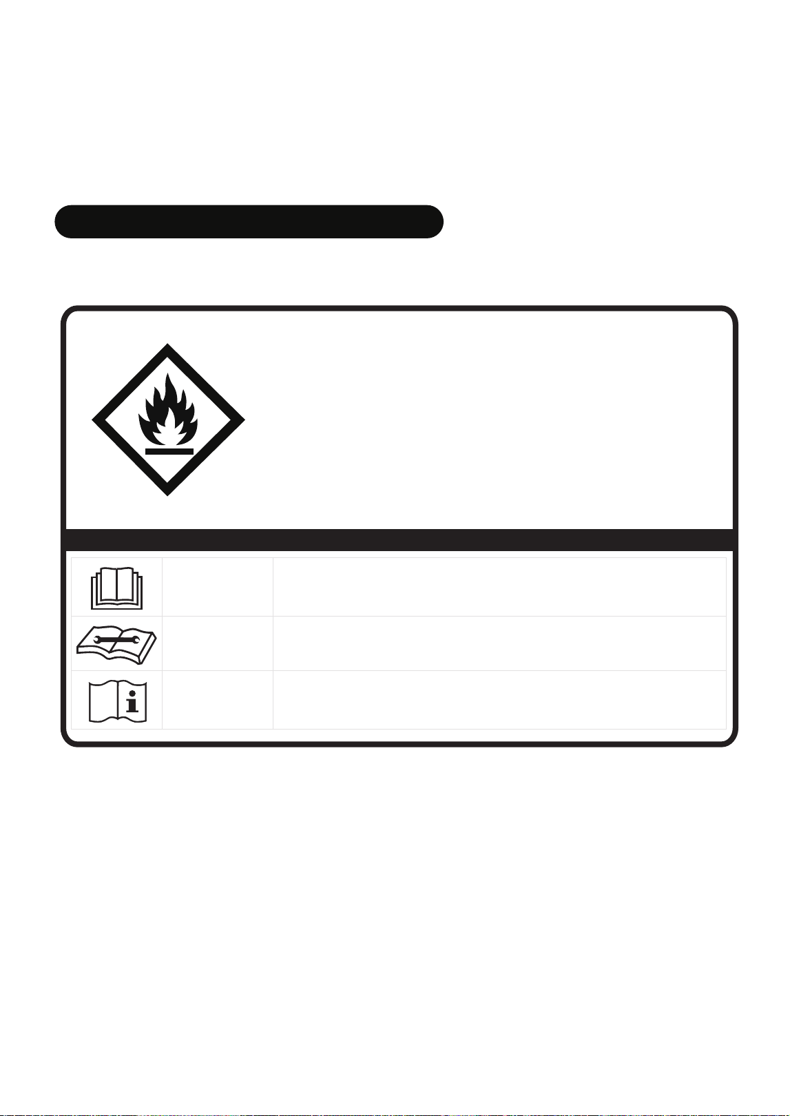
SAFETY
MANUAL
FOR R32 REFRIGERANT MODEL
North America Products
CAUTION:
Risk of fire
flammable materials
IMPORTANT NOTE: Read this manual
carefully before installing or operating
your new appliance unit. Make sure
to save this manual for future reference.
Explanation of symbols displayed on the unit
CAUTION
This symbol shows that the operation manual should be read carefully.
CAUTION
This symbol shows that a service personnel should be handling this
equipment with reference to the installation manual.
CAUTION
This symbol shows that information is available such as the operating
manual or installation manual.
A2L

7
4. Storage of equipment/appliances
The storage of the appliance should be in accordance with the applicable
regulations or instructions, whichever is more stringent.
1. Transport of equipment containing flammable refrigerants
See transport regulations.
2. Marking of equipment using signs
See local regulations.
3. Disposal of equipment using flammable refrigerants
See national regulations.
Flammable
Refrigerant R32 is used within appliance.
-
-
-
-
-
-
When maintaining or disposing the appliance, the refrigerant (R32) shall be
recovered properly, shall not discharge to air directly.
Compliance with national gas regulations shall be observed.
Keep ventilation openings clear of obstruction.
The appliance shall be stored so as to prevent mechanical damage from occurring.
The appliance shall be stored in a well-ventilated area where the room size
corresponds to the room area as specified for operation.
Any person who is involved with working on or breaking into a refrigerant circuit
should hold a current valid certificate from an industry-accredited assessment
authority, which authorises their competence to handle refrigerants safely in
accordance with an industry recognised assessment specification. All training shall
follow the ANNEX HH requirements of UL 60335-2-40 4th Edition.
AVERTISSEMENT
Ne pas utiliser de produits permettant d accélérer le dégel ou de produits de
nettoyage autres que ceux recommandés par le fabricant.
L’appareil doit être entreposé dans un endroit sans source d allumage fonctionnant
en continu (par exemple : flamme nue, appareil au gaz en marche ou radiateur
électrique en marche).
Ne pas percer ni bruler. Attention : les frigorigènes peuvent être inodores.
Examples for such working procedures are:
• breaking into the refrigerating circuit;
• opening of sealed components;
• opening of ventilated enclosures.
-
-
-
-
-
No open fire or device like switch which may generate spark/arcing shall be
around appliance to avoid causing ignition of the flammable refrigerant used.
Please follow the instructions carefully when storing or maintaining the appliance
to prevent mechanical damage from occurring.
Do not use means to accelerate the defrosting process or to clean, other than
those recommended by the manufacturer.
The appliance shall be stored in a room without continuously operating ignition
sources (for example: open flames, an operating gas appliance) and ignition
sourcesor (for example: an operating electric heater) close to the appliance.
Do not pierce or burn.
Be aware that the refrigerants may not contain an odour.

8
8) Checks to the refrigerating equipment
Where electrical components are being changed, they shall be fit for the purpose
and to the correct specifications. At all times the manufacturer's maintenance
and service guidelines shall be followed. If in doubt consult the manufacturer's
technical department for assistance. The following checks shall be applied to
7) ventilated area
Ensure that the area is in the open or that it is adequately ventilated before
breaking into the system or conducting any hot work. A degree of ventilation
shall continue during the period that the work is carried out. The ventilation
should safely disperse any released refrigerant and preferably expel it externally
into the atmosphere.
6) No ignition sources
No person carrying out work in relation to a refrigerating system which involves
exposing any pipe work that contains or has contained flammable refrigerant shall
use any sources of ignition in such a manner that it may lead to the risk of fire or
explosion. All possible ignition sources, including cigarette smoking, should be kept
suciently far away from the site of installation, repairing, removing and disposal,
during which flammable refrigerant can possibly be released to the surrounding
space. Prior to work taking place, the area around the equipment is to be surveyed
to make sure that there are no flammable hazards or ignition risks. No Smoking
signs shall be displayed.
5. Storage of packed (unsold) equipment
Storage package protection should be constructed such that mechanical damage
to the equipment inside the package will not cause a leak of the refrigerant charge.
The maximum number of pieces of equipment permitted to be stored together will
be determined by local regulations.
6. Information on servicing
1) Checks to the area
Prior to beginning work on systems containing flammable refrigerants, safety
checks are necessary to ensure that the risk of ignition is minimised. For repair to
the refrigerating system, the following precautions shall be complied with prior to
conducting work on the system.
2) Work procedure
Work shall be undertaken under a controlled procedure so as to minimise the risk
of a flammable gas or vapour being present while the work is being performed.
3) General work area
All maintenance sta and others working in the local area shall be instructed on the
nature of work being carried out. Work in confined spaces shall be avoided. The
area around the workspace shall be sectioned o. Ensure that the conditions within
the area have been made safe by control of flammable material.
4) Checking for presence of refrigerant
The area shall be checked with an appropriate refrigerating detector prior to and
during work, to ensure the technician is aware of potentially flammable atmospheres.
Ensure that the leak detection equipment being used is suitable for use with
flammable refrigerants, i.e. non-sparking, adequately sealed or intrinsically safe.
5) Presence of fire extinguisher
If any hot work is to be conducted on the refrigeration equipment or any
associated parts, appropriate fire extinguishing equipment shall be available to
hand. Have a dry powder or CO2 fire extinguisher adjacent to the charging area.

9
The following leak detection methods are deemed acceptable for systems containing
flammable refrigerants. Electronic leak detectors shall be used to detect flammable
refrigerants, but the sensitivity may not be adequate, or may need re-calibration.
(Detection equipment shall be calibrated in a refrigerant-free area.)
Ensure that the detector is not a potential source of ignition and is suitable for the
refrigerant used. Leak detection equipment shall be set at a percentage of the LFL of
the refrigerant and shall be calibrated to the refrigerant employed and the appropriate
percentage of gas (25% maximum) is confirmed. Leak detection fluids are suitable for
use with most refrigerants but the use of detergents containing chlorine shall be
avoided as the chlorine may react with the refrigerant and corrode the copper
pipe-work.
If a leak is suspected, all naked flames shall be removed/extinguished. If a leakage of
refrigerant is found which requires brazing, all of the refrigerant shall be recovered
from the system, or isolated (by means of shut o valves) in a part of the system
remote from the leak. Removal of refrigerant shall be according to Removal and
evacuation.
7. Sealed electrical components shall be replaced.
8. Intrinsically safe components must be replaced.
9. Cabling
Check that cabling will not be subject to wear, corrosion, excessive pressure, vibration,
sharp edges or any other adverse environmental eects. The check shall also take into
account the eects of aging or continual vibration from sources such as compressors
or fans.
10. Detection of flammable refrigerants
Under no circumstances shall potential sources of ignition be used in the searching
for or detection of refrigerant leaks. A halide torch (or any other detector using a
naked flame) shall not be used.
installations using flammable refrigerants: the actual refrigerant charge is in
accordance with the room size within which the refrigerant containing parts are
installed; the ventilation machinery and outlets are operating adequately and are
not obstructed; if an indirect refrigerating circuit is being used, the secondary
circuit shall be checked for the presence of refrigerant; marking to the equipment
continues to be visible and legible. markings and signs that are illegible shall be
corrected; and refrigerating pipe or components are installed in a position where
they are unlikely to be exposed to any substance which may corrode refrigerant
containing components, unless the components are constructed of materials
which are inherently resistant to being corroded or are suitably protected against
being so corroded.
9) Checks to electrical devices
Repair and maintenance to electrical components shall include initial safety
checks and component inspection procedures. If a fault exists that could
compromise safety, then no electrical supply shall be connected to the circuit
until it is satisfactorily dealt with. If the fault cannot be corrected immediately
but it is necessary to continue operation, an adequate temporary solution shall
be used. This shall be reported to the owner of the equipment so all parties are
advised. Initial safety checks shall include:
That capacitors are discharged: this shall be done in a safe manner to avoid
possibility of sparking; that there no live electrical components and wiring are
exposed while charging, recovering or purging the system; that there is
continuity of earth bonding.

10
13. Decommissioning
Before carrying out this procedure, it is essential that the technician is completely
familiar with the equipment and all its detail. It is recommended good practice that
all refrigerants are recovered safely. Prior to the task being carried out, an oil and
refrigerant sample shall be taken in case analysis is required prior to re-use of
reclaimed refrigerant. It is essential that electrical power is available before the task
is commenced.
a) Become familiar with the equipment and its operation.
b) Isolate system electrically.
For appliances containing flammable refrigerants, refrigerants purging shall be
achieved by breaking the vacuum in the system with oxygen-free nitrogen and
continuing to fill until the working pressure is achieved, then venting to atmosphere,
and finally pulling down to a vacuum (optional for A2L). This process shall be
repeated until no refrigerant is within the system (optional for A2L). When the final
oxygen-free nitrogen charge is used. the system shall be vented down to
atmospheric pressure to enable work to take place.
The outlet for the vacuum pump shall not be close to any potential ignition sources,
and ventilation shall be available.
12. Charging procedures
In addition to conventional charging procedures, the following requirements shall
be followed. Ensure that contamination of dierent refrigerants does not occur
when using charging equipment. Hoses or lines shall be as short as possible to
minimise the amount of refrigerant contained in them. Cylinders shall be kept in an
appropriate position according to the instructions. Ensure that the refrigeration
system is earthed prior to charging the system with refrigerant. Label the system
when charging is complete (if not already). Extreme care shall be taken not to
overfill the refrigeration system. Prior to recharging the system it shall be pressure
tested with OFN. The system shall be leak tested on completion of charging but
prior to commissioning. A follow up leak test shall be carried out prior to leaving
the site.
11. Removal and evacuation
When breaking into the refrigerant circuit to make repairs—or for any other
purpose - conventional procedures shall be used. However, for flammable
refrigerants it is important that best practice be followed, since flammability is a
consideration. The following procedure shall be adhered to:
-Safely remove refrigerant following local and national regulations;
-Evacuate;
-Purge the circuit with inert gas (optional for A2L);
-Evacuate (optional for A2L);
-continuously flush or purge with inert gas when using flame to open circuit; and
-open the circuit.
The refrigerant charge shall be recovered into the correct recovery cylinders if
venting is not allowed by local and national codes. For appliances containing
flammable refrigerants, the system shall be purged with oxygen-free nitrogen to
render the appliance safe for flammable refrigerants. This process might need to
be repeated several times. Compressed air or oxygen shall not be used for purging
refrigerant systems.

11
14. Labelling
Equipment shall be labelled stating that it has been de-commissioned and emptied
of refrigerant. The label shall be dated and signed.
Ensure that there are labels on the equipment stating the equipment contains
flammable refrigerant.
15. Recovery
When removing refrigerant from a system, either for servicing or decommissioning,
it is recommended good practice that all refrigerants are removed safely.
When transferring refrigerant into cylinders, ensure that only appropriate refrigerant
recovery cylinders are employed. Ensure that the correct number of cylinders for
holding the total system charge is available. All cylinders to be used are designated
for the recovered refrigerant and labelled for that refrigerant (i.e., special cylinders
for the recovery of refrigerant). Cylinders shall be complete with pressure-relief
valve and associated shut-o valves in good working order. Empty recovery
cylinders are evacuated and, if possible, cooled before recovery occurs.
The recovery equipment shall be in good working order with a set of instructions
concerning the equipment that is at hand and shall be suitable for the recovery of
the flammable refrigerant. If in doubt, the manufacturer should be consulted. In
addition, a set of calibrated weighing scales shall be available and in good working
order. Hoses shall be complete with leak-free disconnect couplings and in good
condition.
The recovered refrigerant shall be processed according to local legislation in the
correct recovery cylinder, and the relevant waste transfer note arranged. Do not
mix refrigerants in recovery units and especially not in cylinders.
If compressors or compressor oils are to be removed, ensure that they have been
evacuated to an acceptable level to make certain that flammable refrigerant does
not remain within the lubricant. The compressor body shall not be heated by an
open flame or other ignition sources to accelerate this process. When oil is drained
from a system, it shall be carried out safely.
c) Before attempting the procedure ensure that: mechanical handling equipment is
available, if required, for handling refrigerant cylinders; all personal protective
equipment is available and being used correctly; the recovery process is
supervised at all times by a competent person; recovery equipment and cylinders
conform to the appropriate standards.
d) Pump down refrigerant system, if possible.
e) If a vacuum is not possible, make a manifold so that refrigerant can be removed
from various parts of the system.
f) Make sure that cylinder is situated on the scales before recovery takes place.
g) Start the recovery machine and operate in accordance with instructions.
h) Do not overfill cylinders. (No more than 80% volume liquid charge.)
i) Do not exceed the maximum working pressure of the cylinder, even temporarily.
j) When the cylinders have been filled correctly and the process completed, make
sure that the cylinders and the equipment are removed from site promptly and
all isolation valves on the equipment are closed o.
k) Recovered refrigerant shall not be charged into another refrigeration system
unless it has been cleaned and checked.
Caster

Midea Cube Installation Modes and Installation Video
The Midea Cube dehumidifier can be installed in 4
different modes – Bucket Mode, Bucketless Mode,
Scan this QR code with your mobile device to watch an
installation video of the Midea Cube that walks through
all four installation modes.
Continuous Draining, and Drain Pump Mode (pump
model only)
14
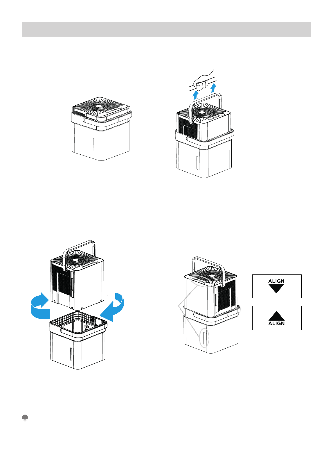
Bucket Mode - Set Up Instructions (Install Video Time 0:36)
Step 1:
Separate dehumidifi er & bucket from the nested shipping/storage position. Remove all packaging materials
from the unit.
Step 2:
Rotate dehumidifi er 90° and align the arrows on the two labels (one on the bucket and one on the dehumidifi er)
and carefully sit the dehumidifi er down onto the bucket.
The water level window in the bucket and the user interface buttons on the dehumidifi er should be on the
same side when properly stacked. Check to ensure the arrows on the unit and bucket are aligned as in Fig. 7c
for proper operation.
Step 3:
Plug the unit in and press the power button and the unit is ready to run in normal (bucket) mode.
Nested Shipping &
Storage Position
Fig. 6a
Fig. 6b
Rotate dehumidifi er 90°
Fig. 7a
User Interface
Buttons and
Water Level
Window
Aligned on the
Same Side
Fig. 7b
Fig. 7c
NOTE
15
See page 21 for operating instructions.
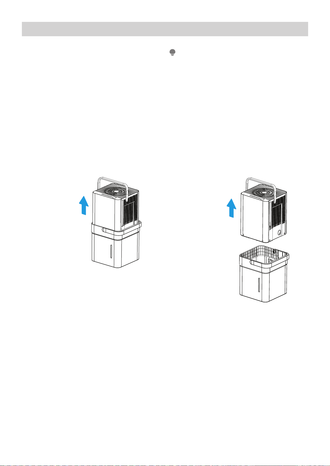
Emptying the Bucket (Time 2:56)
• When the bucket reaches the set Fill Level, the
unit’s display will show P2 regardless of power
status
• Using proper lifting techniques, remove the unit
from the bucket. Be aware, some residual water
may spill from the bottom of the unit while not
on the bucket.
• Using two hands, grab the bucket handle and
carry it to the desired drainage point. Pouring
from a front corner of the bucket (the bucket
window is on the front side), empty the bucket.
If pouring from the back of the bucket, some
water may spill from the relief holes.
• Return the bucket to the desired operating
location and place the unit back on the bucket.
Be sure the unit is aligned properly
• When you remove the unit from the bucket do
not set the unit on any electrical components as
the bottom may be wet
• Do not set the unit on an uneven surface after
removing it from the bucket
• Ensure the unit is seated properly after returning
it to the bucket
• If the unit is removed from the bucket during
operation, the display will show the error code Eb
and cease operation until returned to the bucket
or changed to bucketless mode.
NOTE
1. Lift the unit off
the bucket and
place it on a
level surface.
2. Lift the bucket
using 2 hands
and carry it
to a drainage
point.
3. Pour out all
the water.
Fig. 9
Fig. 8
16
Bucketless Mode – Set Up Instructions (Install Video Time 3:32)
Bucketless mode allows you to run the unit in continuous drain mode without the bucket in place, best for use
in smaller spaces.
Bucketless mode must be enabled within 3 minutes of plugging in the dehumidifi er, so it is best to set up
the unit for this operation before powering on the unit.
NOTE
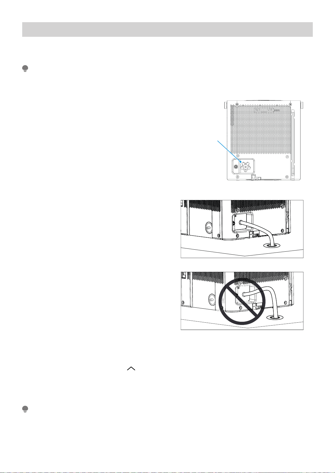
Step 1:
Set the unit directly on the surface or fl oor of the
area to be dehumidifi ed. Remove the drain cap from
the continuous drain port at the back of the unit.
Step 2:
Insert the continuous drain hose into the continuous
drain port at the back of the unit. Set the other end
of the hose in the drain, ensuring the hose slopes
down and does not raise above the drain port.
Step 3:
Plug in the dehumidifi er. Press the UP ( ) and FILL LEVEL buttons simultaneously for 3 seconds. The
bucketless mode icon will appear in the bottom right of the display when the unit is ready to operate in
bucketless mode (see UI on page for example).
To remove the unit from bucketless mode, place the unit back on the bucket.
See page for operating instructions.
NOTE
Fig. 10
Fig. 11
Fig. 12
Remove drain
cap by rotating
counter-clockwise
17
21
21
Continuous Draining - Set Up Instructions (Install Video Time 4:39)
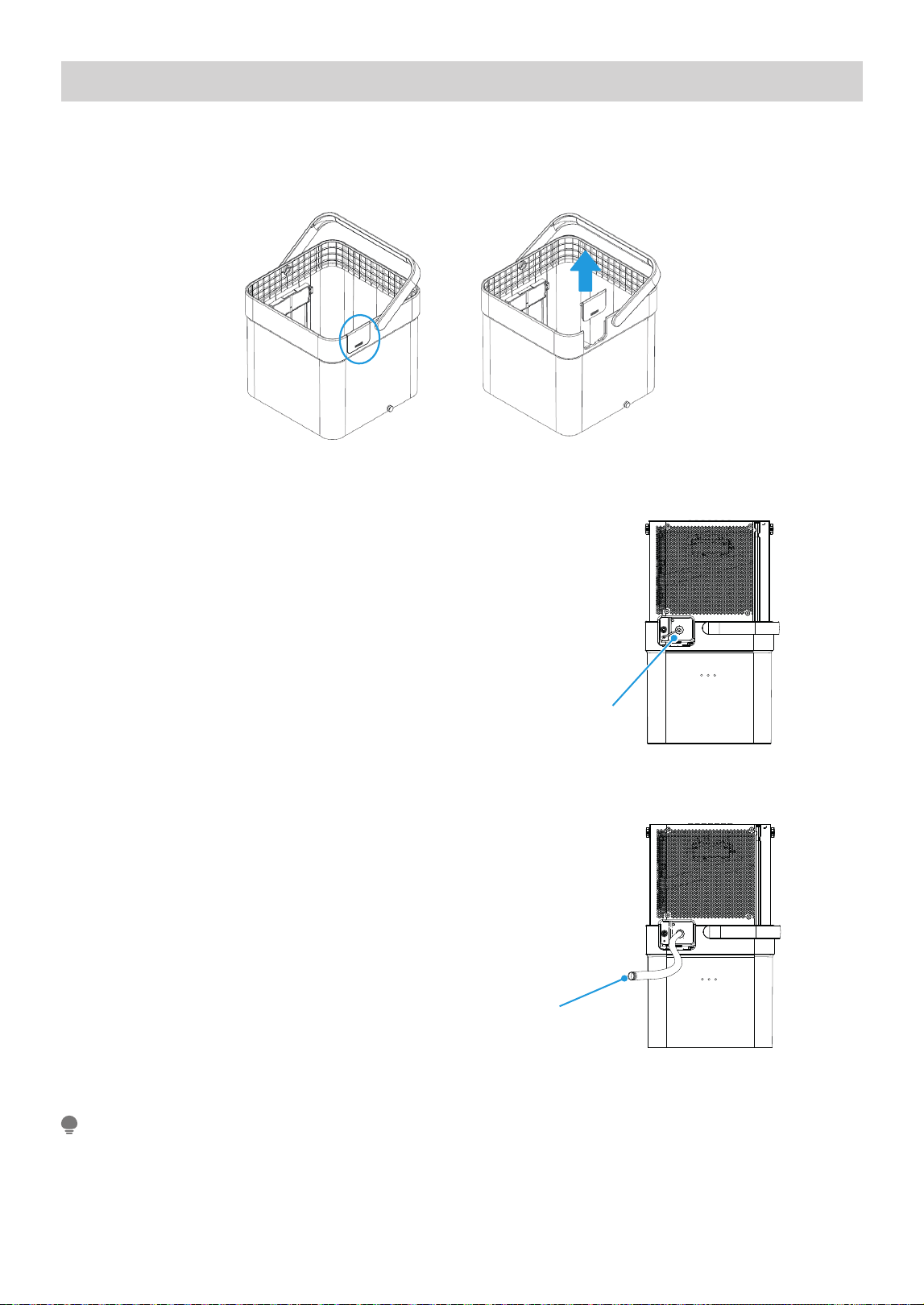
Step 1:
Before placing the unit on the bucket, remove the continuous drain cover from the back of the bucket.
Make sure to keep the cover if you ever plan to change operating modes.
Step 2:
Place the unit onto the bucket. Remove the
continuous drain plug cover and insert the included
continuous drain hose. You can also attach and use
a garden hose by screwing it on to the drain port.
Check to make sure the hose is properly seated.
Step 3:
Place the other end of the drain hose on or in the
drain. Ensure the unit is placed at a height where the
unit drain port is above the drain hose outlet. This
will ensure proper draining.
Note that the bucket fi ll level LEDS do not operate
when the continuous drain hose is installed.
See page for operating instructions.
NOTE
Fig. 13bFig. 13a
Remove the plastic
cover rotating
counter-clockwise
Fig. 14
Drain hose
Fig. 15
18
21
Drain Pump Mode - Set Up Instructions (Install Video Time 5:43)
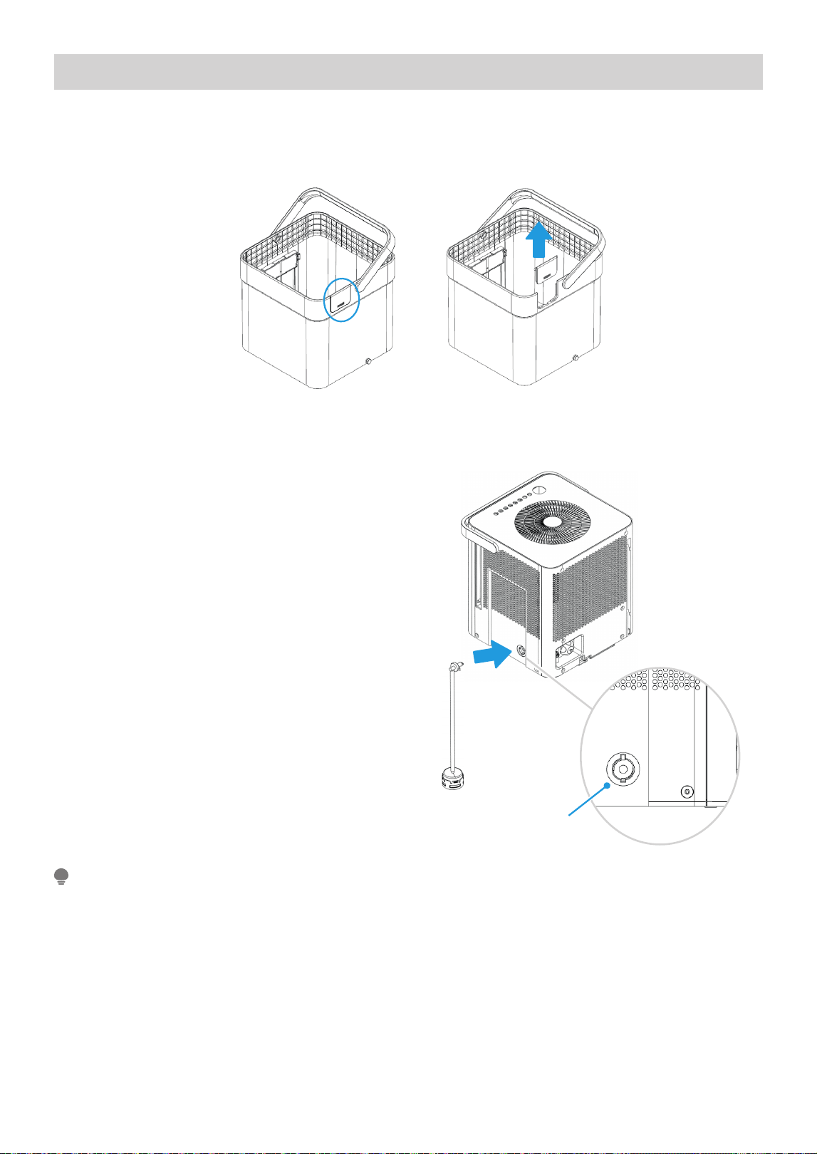
Step 1:
Before placing the unit on the bucket, remove the continuous drain cover from the back of the bucket. Make
sure to keep the cover if you ever plan to change operating modes.
Fig. 16bFig. 16a
Step 2:
Install the pump inlet hose by pressing the hose fi tting
into the connection located on the side of the unit.
Rotate the fi tting in the connection 90 degrees to lock
it in place and ensure it is fully seated.
Step 3:
Lift the dehumidifier and set it onto the bucket. Make
sure the unit is properly aligned with the bucket and
that the pump sits inside the bucket. The pump must
be placed in the bucket in order to pump water out of
the bucket.
Pump drain hose
inlet connection
Fig. 17
The pump will not activate until the water
reaches the level 4 fill level inside the bucket.
When the pump stops running, some water will
remain in the bucket - this is to keep the pump
inlet submerged and prevent the pump from
pumping air, which can cause damage to the pump.
NOTE
19
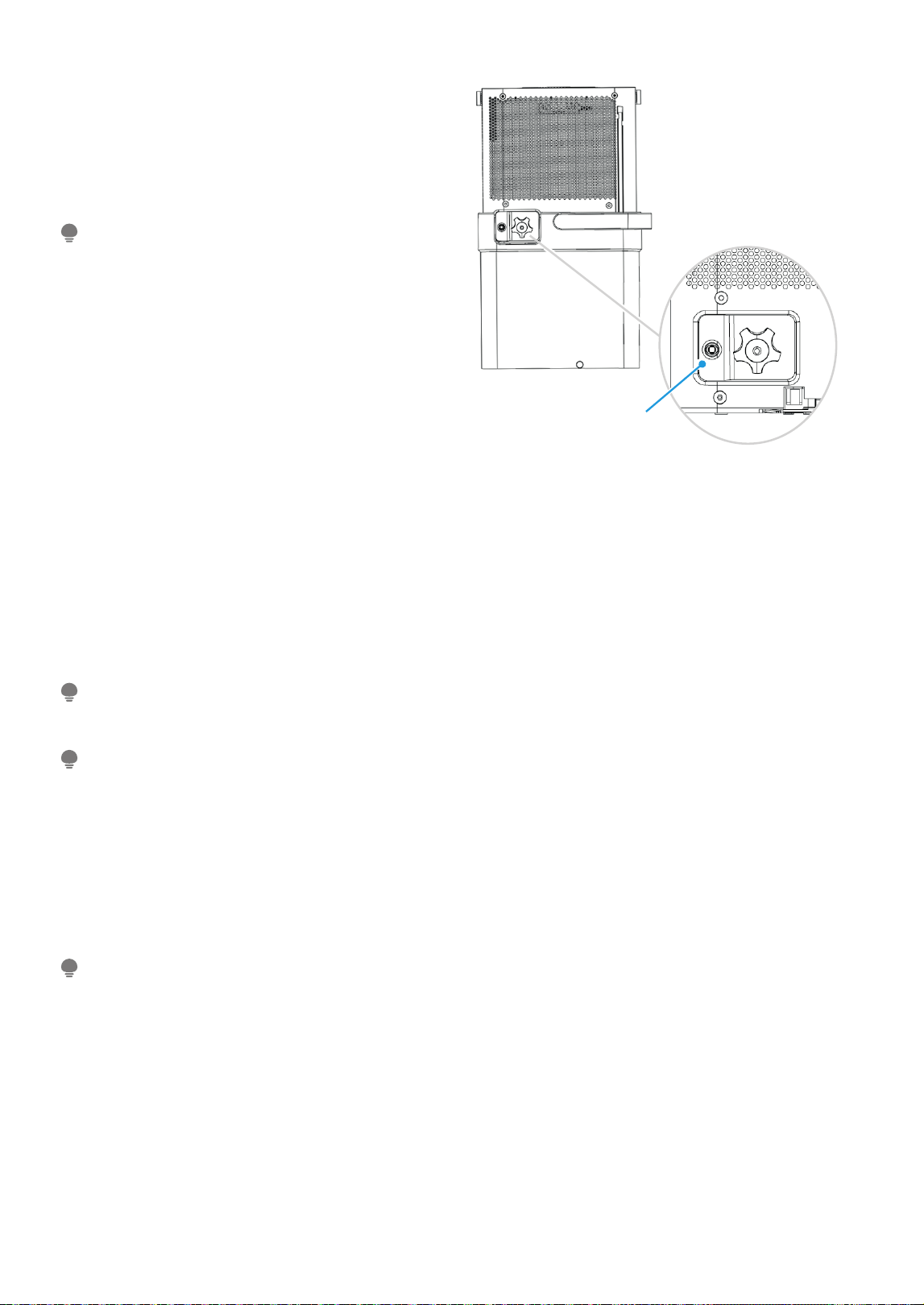
Step 4:
Insert the pump drain hose to the back of the
dehumidifier, using the connection next to the
continuous drain port. Check to make sure the
pump drain hose is fully seated in the pump drain
connector.
Step 5:
Set the other end of the pump drain hose in the desired drain location, noting that the pump can pump up to 14
feet above the drain port to an elevated drain location.
Step 6:
for example).
Note that the bucket Fill level LEDs do not operate when the pump drain hose is installed.
Pump drain hose
inlet connection
Fig. 18
To remove the pump hose, push in on the collar
around the hose while pulling the hose out.
NOTE
The pump may generate a loud noise for the first 3 to 5 minutes of operation.
NOTE
If routing the drain hose outdoors, do not operate when the outdoor temperature is at or below 32°F (0°C)
as the water will freeze, blocking the hose and causing the unit to stop.
Make sure to empty the bucket at least once a week when using the pump draining feature. When the pump
draining feature is not being used, remove the pump drain hose from the outlet.
NOTE
The pump operation light blinks when a failure occurs. Please turn off the unit and disconnect the power cord.
Check the following items:
• Cleaning the pump
filter.
• Refer to “Cleaning and Maintenance” section for details on cleaning the pump filter.
• Check if the drain hose is clean and free of debris.
• Empty the water from the bucket.
• Check the hose connection and the bucket for proper
fitment. If the error persists, contact customer service.
NOTE
20
21
Initiate pump mode by pressing FILL LEVEL Button for 3 seconds.The pumpindicator will appear at the top left of
the unit’s display when the unit is ready to operate in pump mode (see UI on page
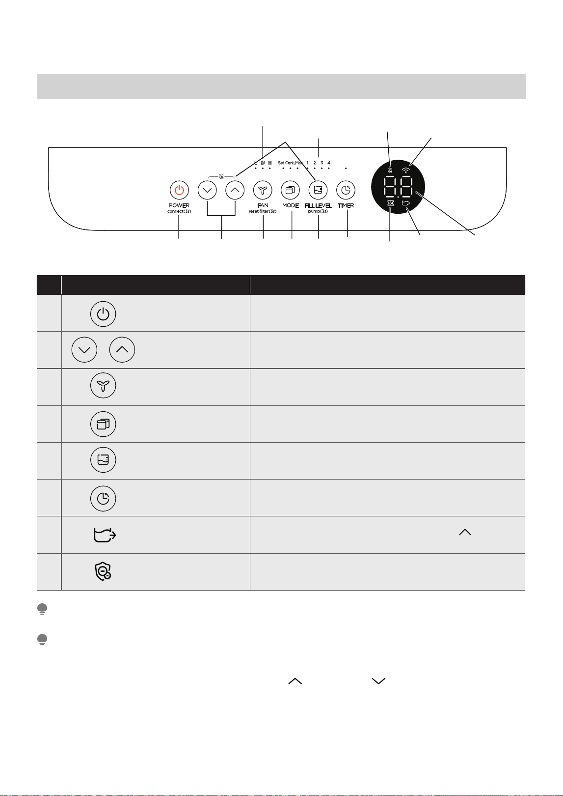
OPERATION INSTRUCTIONS
Control Panel Features
Description
1 ON / OFF
• Press to turn unit on or off.
• Press for 3 sec to initiate smart connection mode.
2
UP / DOWN
Buttons
• Press to set humidity and timer.
3
FAN Button
• Press to select the Fan Speed in two steps - High and Low.
•
4
MODE Button
• Press to choose operating mode in a sequence that goes
from Set, Max and Cont.
5
FILL LEVEL Button
• Press this button to change the water level at which the
• Press for 3 sec to activate pump mode.
bucket full switch activates.
6
7
8
TIMER Button
Bucketless Mode
Air Magic+
• Press to turn unit Auto Start/Stop.
• Press and hold FILL LEVEL button and UP ( )button for
3 sec to turn on/off bucketless mode
• Press and hold on the Up and Down buttons 2 sec to
initiate/stop Air Magic+ feature
Control Pads: When you push the button to change operation modes, the unit will make a beep sound to
indicate that it is changing modes.
NOTE
The appearance of the control panel on your unit may vary slightly. Functions will be similar.
NOTE
1. POWER BUTTON (ON/OFF):
Press to turn the dehumidifier on and off.
CONNECT:
Holding the power button for 3 seconds will
place the unit in network connection mode to
setup wireless control.
2. UP ( ) AND DOWN ( ) BUTTONS:
Press these buttons to adjust the setpoint or to set the
time feature.
Press for 3 sec to turn off the cleaning filter reminder.
43
7
2/81 65
Fill Level
Button and
Indicators
Pump
Indicator
(some models)
Network
Connection
Indicator
LED Display
Bucketless
Indicator
Filter Indicator
21
Air Magic+
Indicator
Model
MAD50PS1BQGR
8. Air Magic+ feature(Air purification function)
7. Bucketless mode
The dehumidifier can be used without bucket. For
the first time connect to the power, the LED
DISPLAY shows”Eb”. Press and hold FILL LEVEL
button and UP ( )button for 3 seconds to clear
“Eb” malfunction in 3 minutes, and the bucketless
mode indicator light illuminates.
Press and hold on the Up/Down buttons 2 seconds
to initiate Air Magic+ feature, and the Air Magic+
indicator light illuminates.The ion generatoris
energized feature will help to purify the air inside.
Press and hold on the Up/Down buttons 2 seconds
again to stop Air Magic+ feature, and the Air
Magic+ indicator light turns dark.

Error Codes:
EH60 - Room temperature sensor error--Unplug the
unit and plug it back in. If error repeats, call
for service;
EH61 - Tube Temperature sensor of the evaporator
error--Unplug the unit and plug it back in.
If error repeats, call for service; EH0b-Display
board and master control board communication
error.Unplug the unit and plug it back in. If error
repeats, call for service;
Protection Code:
Note: When one of the above malfunctions occurs,
turn off the unit, and check for any obstructions.
Restart the unit, if the malfunction is still present,
turn off the unit and unplug the power cord. Contact
the manufacturer or its service agents or a similar
qualified person for service.
P2 - Bucket is full -- Empty the bucket and replace it
in the right position.
Eb - Bucket malfunction--Replace the bucket in the
right position, the malfunction clear.

APP INSTRUCTIONS
Specifi cation of Wireless Module
Model: US-SK105 Dimensions: 41 x 24 x 5 (mm)
Antenna Type: Printed PCB Antenna Operation Temperature: 0°C ~ 45°C / 32°F ~ 113°F
Frequency: WLAN 2400-2483.5 MHz Operation Humidity: 10% ~ 85%
Maximum Transmitted Power: <20 dBm Max Power Input: DC 5V/ 00 mA
Precautions
App Compatibility:
• The app is available for both iOS and Android, however older versions may no longer be compatible.
Please keep the app updated with the latest version. Midea makes no guarantee of compatibility and is not
responsible for issues arising as a consequence thereof.
Wireless Security:
• The Smart Kit supports the following security protocols: WPA-PSK / WPA2-PSK / WPA3-SAE.
• It may be used with or without encryption although encryption is strongly recommended.
Connectivity:
• Network issues may occasionally cause timeouts. The unit display and the app may become unsynchronized
but this will resolve itself when the network is restored.
• Should the network remain unavailable, it might be necessary to run the confi guration process again.
• Change in the wireless network will require reconfi guration of the device.
Confi guration:
• The actual network confi guration process may vary slightly from the manual.
• Please check the service website for more information.
Midea will not be responsible for any problems that could be caused by incompatibility or network issues, your
wireless router and mobile phone.
NOTE
24
5
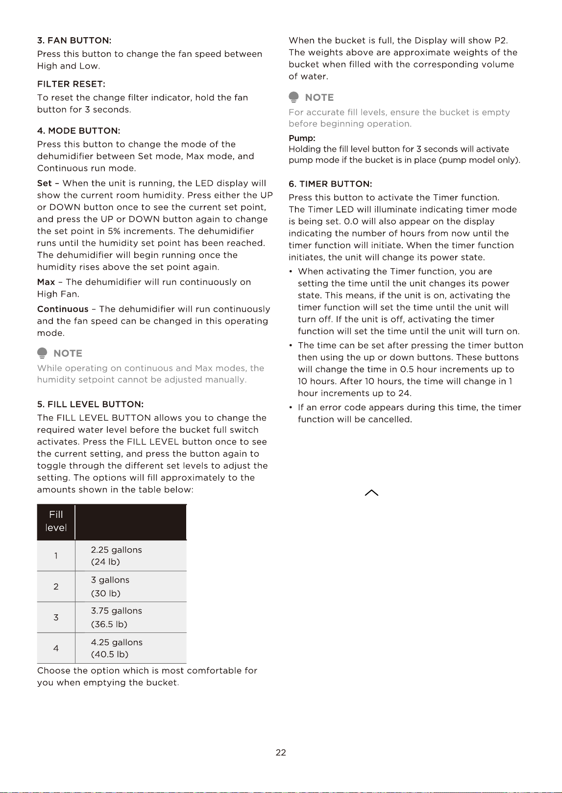
Using the SmartHome App
Step 1: Download the SmartHome app
Scan the QR code below to download the
SmartHome app from app store or search for
it directly on the Google Play Store or Apple’s
App Store.
Download the app
& activate product
Step 2: Log in
Open the SmartHome app. Log in directly if you have an existing
SmartHome account or create a new account. Alternatively, you can
also use a 3rd party login platform.
Step 3: Connecting the device
1) When you log in, you may see the message “Smart devices
discovered nearby”. Tap to add your device.
Ensure that your mobile phone is connected to the wireless network. Bluetooth must be turned on.
The device must also be powered up.
CAUTION
25
Dehumidifier
52%
38%
45%
55% 70%
Target Humidity
Low Med High
Fan Speed
Room humidity 52%
Power
SmartHome
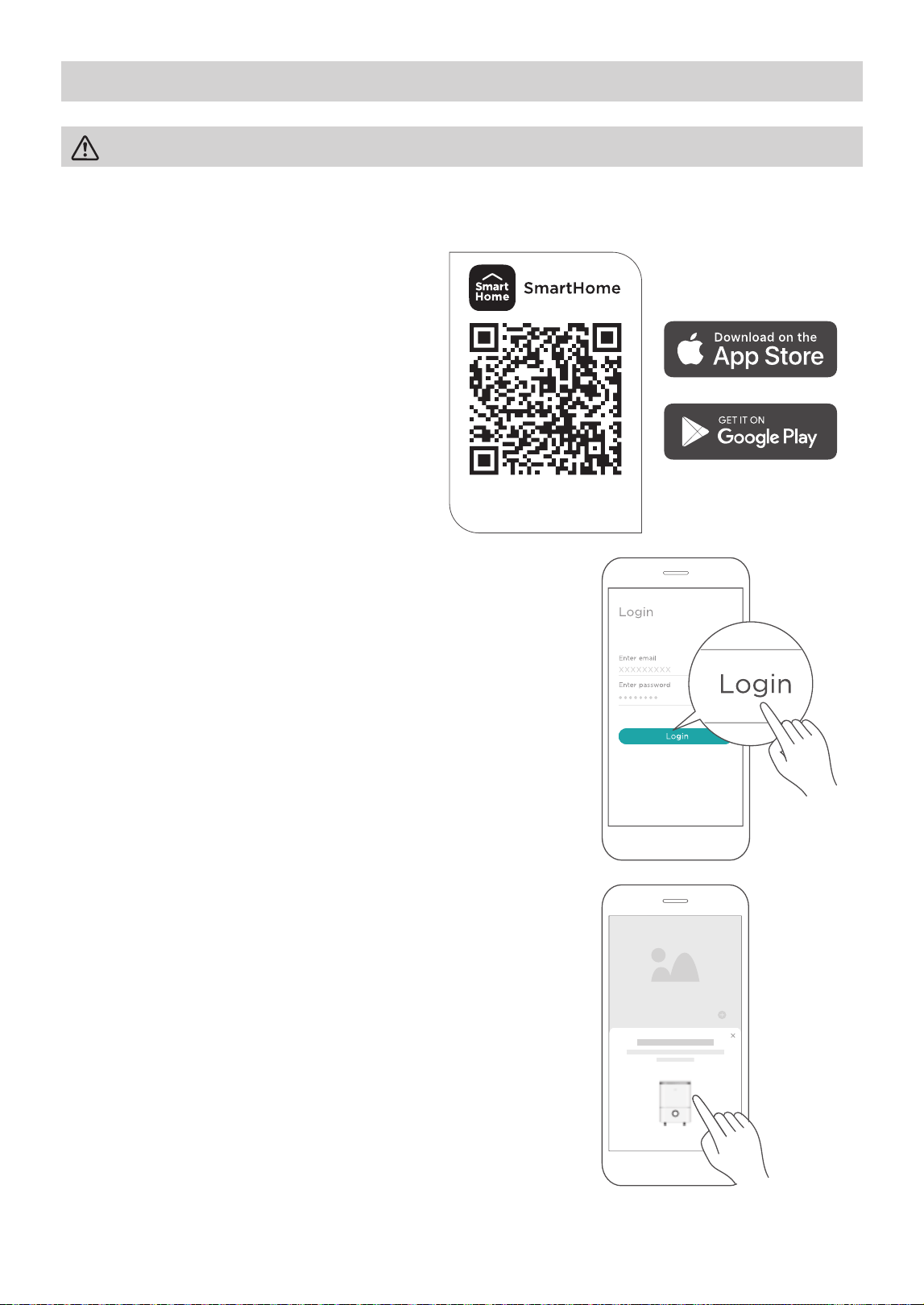
Add device
2) If no such message appears, proceed as follows:
Tap on “+” and select your device in the list of nearby
available devices.
If your device is not listed, please add your device manually,
fi rst selecting the device category e.g. Dehumidifi er.
3) Follow the steps in the app to connect your device to the
wireless network. If your device fails to connect, follow the
additional instructions in the app.
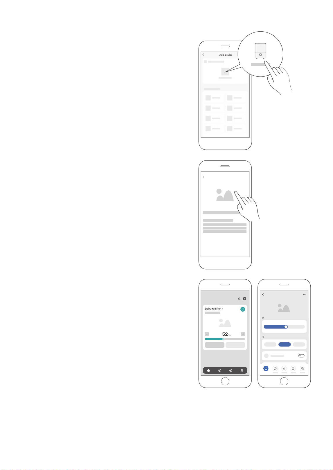
Step 4: Controlling the device
After pairing successfully, a card will be created for the device in
the SmartHome app.
Shortcuts for basic functions will appear on the card such as
changing the humidity or switching the device on or off.
Tapping on the card, will reveal additional features and settings.
The actual design may look different from examples due to
app updates.
26

Compliance
We, hereby declare that this dehumidifi er is in compliance with the relevant provisions of RE Directive
2014/53/EU. A copy of the full DoC is attached (Europen Union products only).
Wireless module models:
US-SK105:
FCC ID: 2ADQOMDNA21
IC: 12575A-MDNA21
This device complies with Part 15 of the FCC Rules and it contains licence exempt transmitter(s) / receiver(s)
that comply with Innovation, Science and Economic Development Canada’s licence-exempt RSS(s).
Operation is subject to the following two conditions:
(1) This device may not cause harmful interference;
the device.
Only operate the device in accordance with the instructions supplied.
Changes or modifi cations to this unit not expressly approved by the party responsible for compliance could
void the user’s authority to operate the equipment.
This device complies with FCC radiation exposure limits set forth for an uncontrolled environment. In order to
avoid the possibility of exceeding the FCC radio frequency exposure limits, human proximity to the antenna
shall not be less than 20cm (8 in) during normal operation.
This equipment has been tested and found to comply with the limits for a Class B digital device, pursuant to part
15 of the FCC Rules. These limits are designed to provide reasonable protection against harmful interference
in a residential installation. This equipment generates, uses and can radiate radio frequency energy and, if not
installed and used in accordance with the instructions, may cause harmful interference to radio communications.
However, there is no guarantee that interference will not occur in a particular installation. If this equipment does
cause harmful interference to radio or television reception, which can be determined by turning the equipment
off and on, the user is encouraged to try to correct the interference by one or more of the following measures:
• Reorient or relocate the receiving antenna.
• Connect the equipment into an outlet on a circuit different from that to which the receiver is connected.
• Consult the dealer or an experienced radio/TV technician for help.
NOTE
(2) This device must accept any interference, including interference that may cause undesired operation of
27
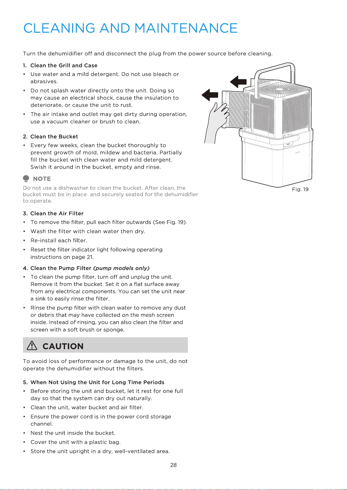
Filters on the left
and right sides
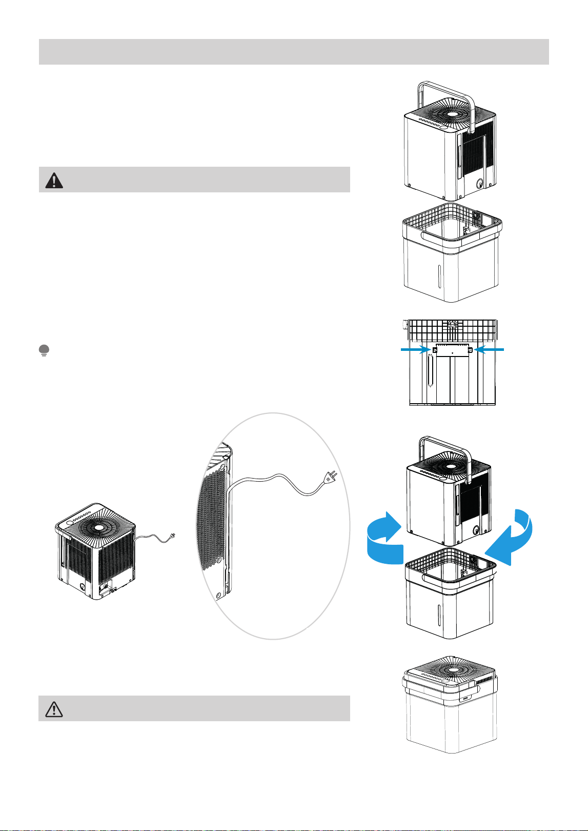
Nesting and Storing Instructions
Step 1:
Power off and unplug the unit. Then lift the dehumidifi er off the
bucket.
Step 2:
Empty all water from bucket.
Fig. 21
Fig. 20
Fig. 23
Step 3:
Make sure to press the tabs on the inside bucket feature in so that
the unit can nest correctly. See Fig. 21.
Step 4:
Rotate dehumidifi er 90° in either direction and insert into bucket
to nest.
Step 5:
The dehumidifi er is nested and ready to store.
CAUTION
When carrying the nested unit, be sure and use the bucket handle
to ensure both the dehumidifi er and bucket are safely carried.
Make sure the power cord is properly tucked into the power cord
storage channel on the back of the dehumidifi er to prevent damage.
NOTE
WARNING
Make sure the bucket is empty before nesting the dehumidifi er to
avoid risk of electrical shock.
Fig. 22aFig. 22b
29

TROUBLESHOOTING TIPS
Problem Solution
Unit does not start
Make sure the dehumidifi er plug is connected fi rmly into the wall outlet.
Check the house fuse/circuit breaker box.
Dehumidifi er has reached its preset level or bucket is full.
Water bucket is not in the proper position.
Dehumidifi er does not dry
the air as it should
Not enough time to remove the moisture.
Make sure there are no curtains, blinds or furniture blocking the front or back
of the dehumidifi er.
The humidity control may not be set low enough.
Check that all doors, windows and other openings are securely closed.
Room temperature is too low, below 5°C (41°F).
There is a water vapor source in the room.
The unit makes a loud
noise when operating
Air fi lter may be dirty. Clean fi lter. Refer to Care and Cleaning section.
The unit is tilted instead of upright as it should be.
The fl oor surface is not level.
Frost appears on the coils This is normal. The dehumidifi er has Auto defrost feature.
Water on fl oor
Hose to connector or hose connection may be loose.
Intended to use the bucket to collect water, but the back drain plug is removed.
ES, AS, P2, EC, Eb and E3
appear in the display
These are error codes and protection code. Check Operating Instructions.
The pump operation on
light blinks at 1 Hz
Clean the pump fi lter.
Check the pump hose is not blocked or leaking.
Empty the water bucket.
When operating in
bucketless mode, water
collects around the
bottom of the unit
Check to ensure the unit is level, and there is no debris on the surface.
Check the drain hose connection and ensure it is properly seated in the outlet.
For additional support and troubleshooting tips, visit the “Help” tab
Before calling for service, review this list. It may save you time and expense. This list includes common
occurrences that are not the result of defective workmanship or materials in this appliance.
Malfunction Diagnosis
within the SmartHome app.
Unit will not connect to
Wireless or App does not
work.
30
WARRANTY
31
•
•
One year full warranty from the date of delivery or the purchase date, whichever is later.
The date of delivery establishes the warranty period, should service be required.

2025
16122000A82676
20250122
CD001UI-DM(NEW)A