Scan to view on YouTube
Installation Video
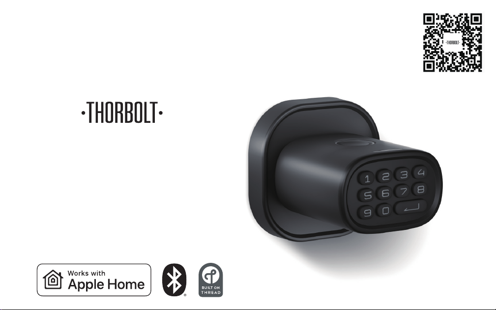
Smart Fingerprint Door Knob with Keypad
MK1
Installation Guide & User Manual

Customer Support
www.thorbolt.co
Thank you for choosing MK1 Fingerprint Door Knob with Keypad!
MK1 takes indoor room security to the next level. The robust and stylish body is
constructed by rigorously selected Aluminum and Zinc Alloy materials. Unlike any
traditional door knob, MK1 enables you to manage up to 100 passcodes and 100
fingerprints, opening up multiple possibilities for various use cases.
MK1 works with Apple Home over the future-proof wireless technology, Thread. It
is faster, more reliable, and more secure. With your Thread-enabled apple home
hub, you can lock/unlock your door and check the status using Siri or your iOS
device at anytime, from anywhere. Our Sleekpoint app provides a ton of exclusive
features for your day-to-day use: access management, activity feed and useful
settings, etc. With our power-saving technologies, 4 AA batteries are able to
provide up to 1 year of battery life. You may finally be able to put your keys away
and use them as backup.
For now, please be sure to explore all of its features outlined in this manual. If you
have any questions, feel free to just drop us an email anytime. We’d love to assist
you to get the most out of it!
Hello!
1
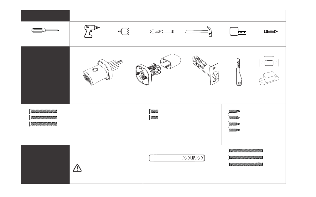
What’s in the Box
2
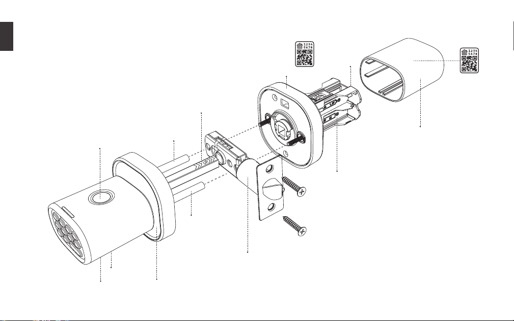
Interior Assembly
Rod Bolt
Rod Bolt
Square Spindle
USB-C Port
Key Hole
Exterior Assembly
Latch Assembly
Battery Compartment
Interior Cover
Fingerprint
Sensor
HomeKit
QR Code
3
Phillips Screwdriver
Drill Hole Saw Drill Chisel Hammer Tape Measure Pencil
Tools
Additional
Exterior Assembly Interior Assembly Latch Assembly Key x 2 Strike Plate
Strike Box
Parts
Optional Parts
M4 Screw x 3
1-2/5” (35mm)
For door thickness
1-3/8” - 1-3/4” (35 - 45mm)
For door thickness
1-3/4” - 2-1/4” (46 - 58mm)
Strike Plate
Screws x 4
4/5” (20mm)
M3 Screws x 2
1/4” (6mm)
(Contact Customer
Service if needed)
M4 Screws x 3
1-3/4” (45mm)
Long Square Spindle
[*2 on door knob set, 1 spare] [*1 on door knob set, 1 spare]
2-3/4” (70mm) backset
is required
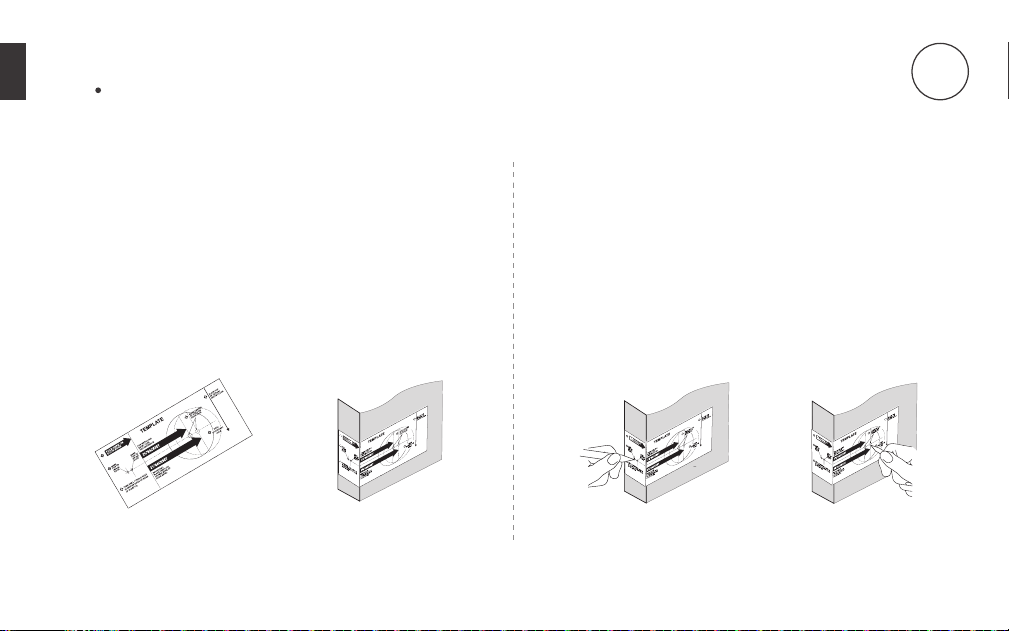
Prepare the door and check dimensions
1. Prepare door and jamb
a. Take out the ‘Door Marking Template’ (Figure 1a).
b. Fold template and place on door 36” (915mm)
from the ground as marked (Figure 1b).
2. Mark the door for drilling
a. Mark center hole on door edge through guide on
template for 1” (25mm) latch bolt (Figure 2a).
b. Mark center hole on door face through guide
on template for 2-3/8” (60mm) or 2-3/4” (70mm)
backset (Figure 2b).
-1a-
-1b- -2a- -2b-
4
For installation on new doors
1
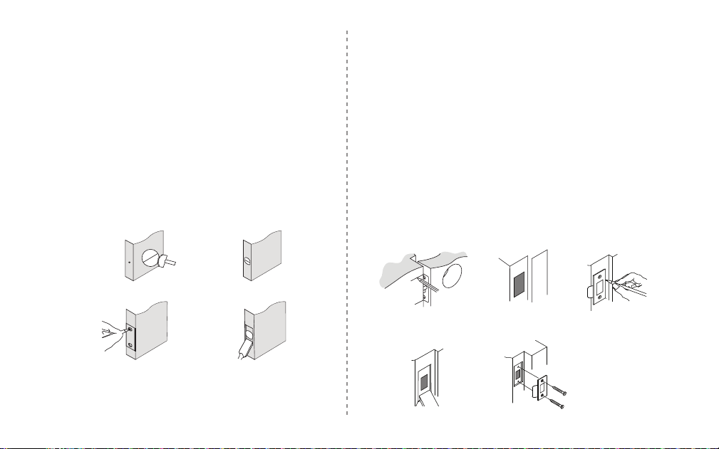
3. Drill and chisel door
a. Drill 2-1/8” (54mm) hole through door face as
marked for lock set (Figure 3a).
b. Drill 1” (25mm) hole in center of door edge for
Latch Assembly (Figure 3b).
c. Insert Latch Assembly in hole keeping it parallel to
face of door. Mark outline and remove latch
(Figure 3c).
d. Chisel 1/8” (3mm) deep or until latch face is flush
with door edge (Figure 3d).
-4a- -4b- -4c-
-4d- -4e-
a. Mark center hole on edge of jamb even with the
center of the Latch Bolt on door edge (Figure 4a).
b. Drill a hole in door jamb on center mark. Check if
the strike box measure can perfectly fits in
(Figure 4b).
c. Outline outside edges of Strike Plate (Figure 4c).
d. Chisel 1/8” (3mm) deep for Strike Plate or until
flush (Figure 4d).
e. Install Strike Plate using two 4/5” (20mm) screws
provided (Figure 4e).
4. Mark and drill door jamb
NOTE:
For drive in Latch, drill hole size indicated on template
and press until it is flush with door edge.
5
2
5mm
54mm
-3a- -3b-
-3c- -3d-
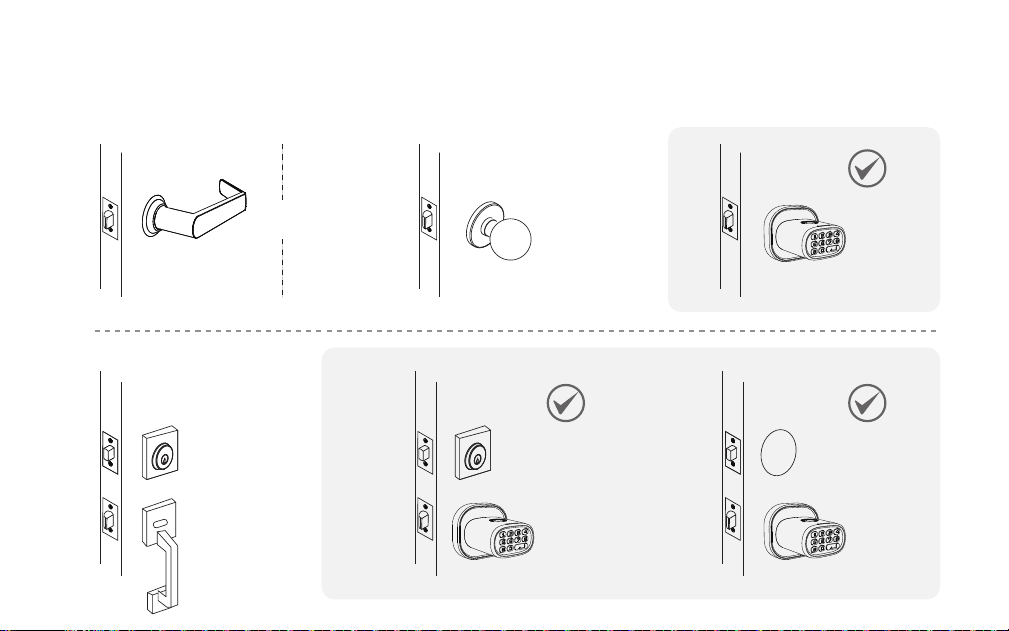
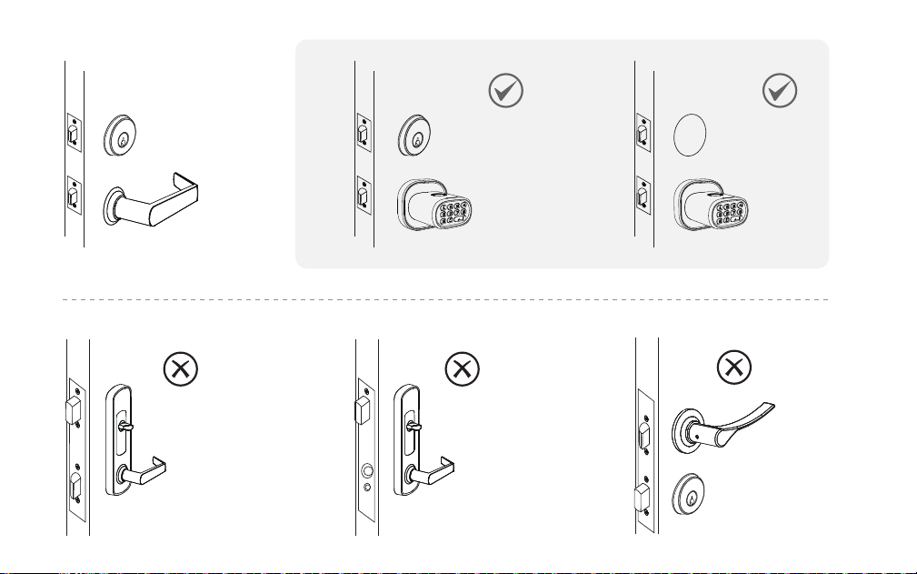
1. Check door compatibility / Remove existing door knob (if applicable)
OR
6
For installation on doors with pre-drilled holes
7
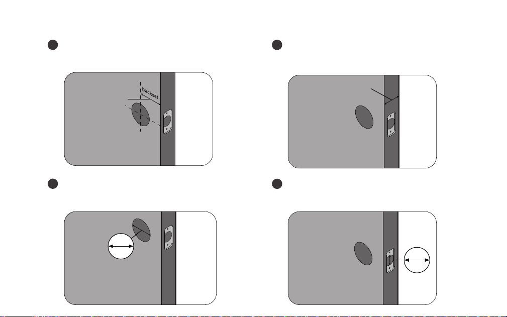
2. Double check door dimensions
Backset: measure to confirm that the
backset is either 2-3/8" or 2-3/4" (60 or 70mm).
Thickness: measure to confirm that the door
is between 1-1/4" to 2-1/4" (35mm to 58mm) thick.
Hole in the door: measure to confirm
that the hole in the door is 2-1/8" (54mm).
Hole in the door edge: measure to confirm
that the hole in the door edge is 1" (25mm).
1
2
3
4
8
1-1/4"- 2-1/4"
35 - 58mm
2-3/8"or 2-3/4"
60 or 70mm
54mm
25mm
2-1/8"
1"
Batteries
This lock requires 4 AA Alkaline batteries from a
single brand (Duracell or Energizer recommended)
to be purchased separately. For best result, 1.2V
rechargeable batteries are NOT recommended.
When all 4 batteries are installed in the correct
position, you will hear a long beep and the indicator
lights will illuminate.
DO NOT mix new batteries with used
batteries when the product is in use. Use
brand new batteries from a single brand.
DO NOT use an electric screwdriver,
only hand tighten screws with Phillips
screwdriver.
DO NOT install this product if your door
thickness is out of range.
DO NOT over-tighten screws.
DO NOT mix new batteries with used
batteries when the product is in use. Use
brand new batteries from a single brand.
DO NOT keep your keys inside.
9
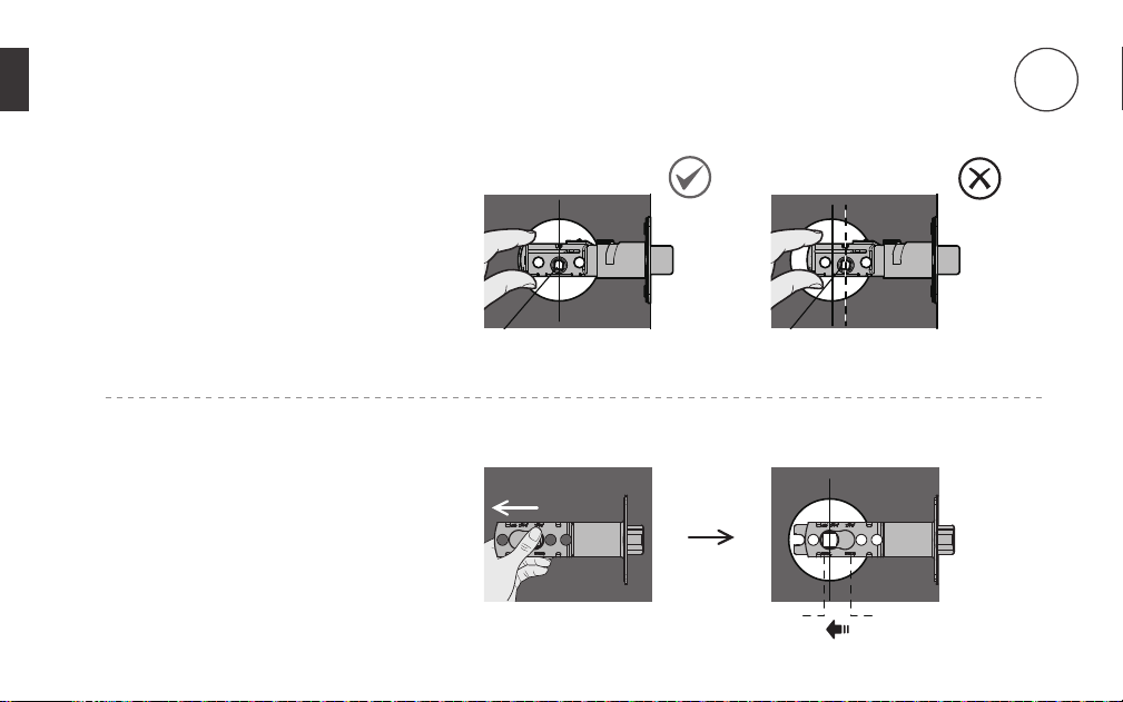
Hold the latch in front of the door
hole, with the latch face flush against
the door edge. Make sure the
square-shaped hole is centered.
For 2-3/4“ (70mm) backset, pull to
extend the latch in order to center
the squared-shaped hole.
Install the Latch and Strike Plate
10
60mm70mm
2

In most cases, the existing strike plate is ready to
be used. You may store the strike plate in box for
future use.
If not, please make sure the bolt is aligned
correctly with the strike plate.
Install the latch
using screws.
Facing door Jamb
11
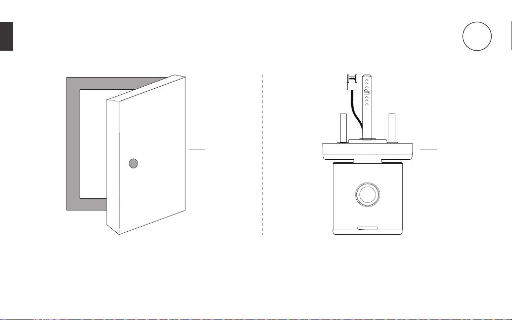
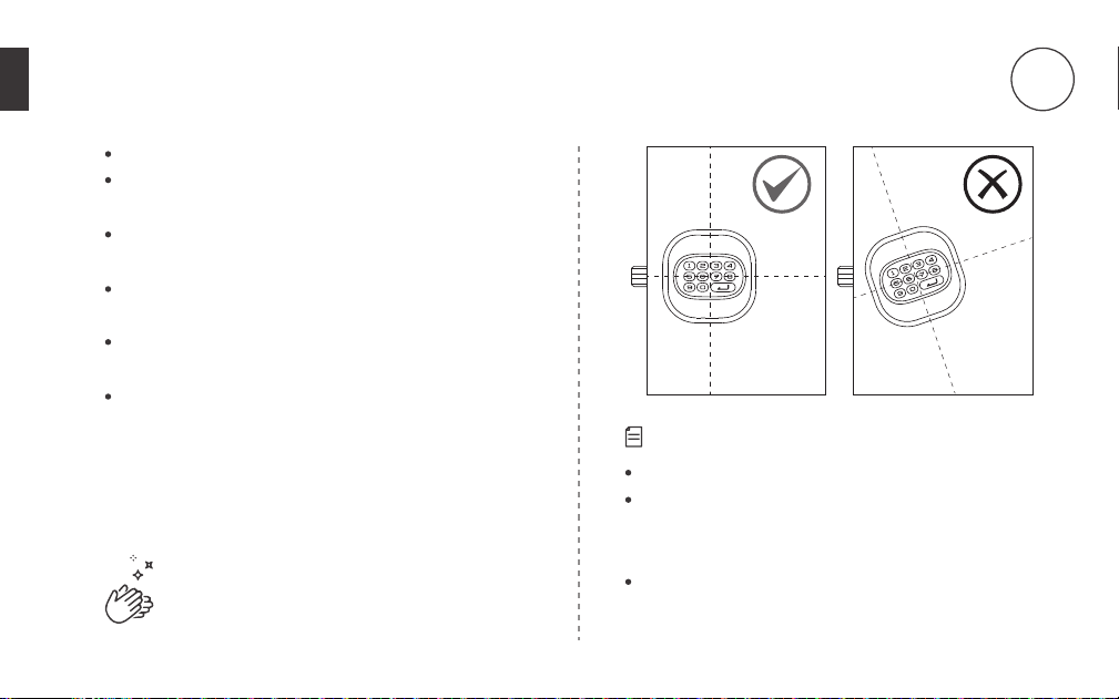
Make sure the door is open. Make sure the fingerprint sensor
and indicator light face upward.
Install the Exterior Assembly
1
12
3
2
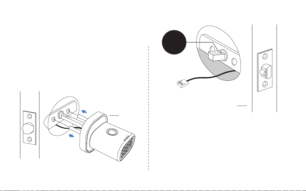
Insert the Exterior Assembly onto the door with the
rod bolts going through the round holes on the
latch, the square spindle going through the center
hole on the latch and the control wire going through
the door hole below the latch.
Forcing the control wire into any other place than
specified above will damage the connector, making
the door knob unusable.
The “UP” mark on the spindle should face upward
13
3
UP
4
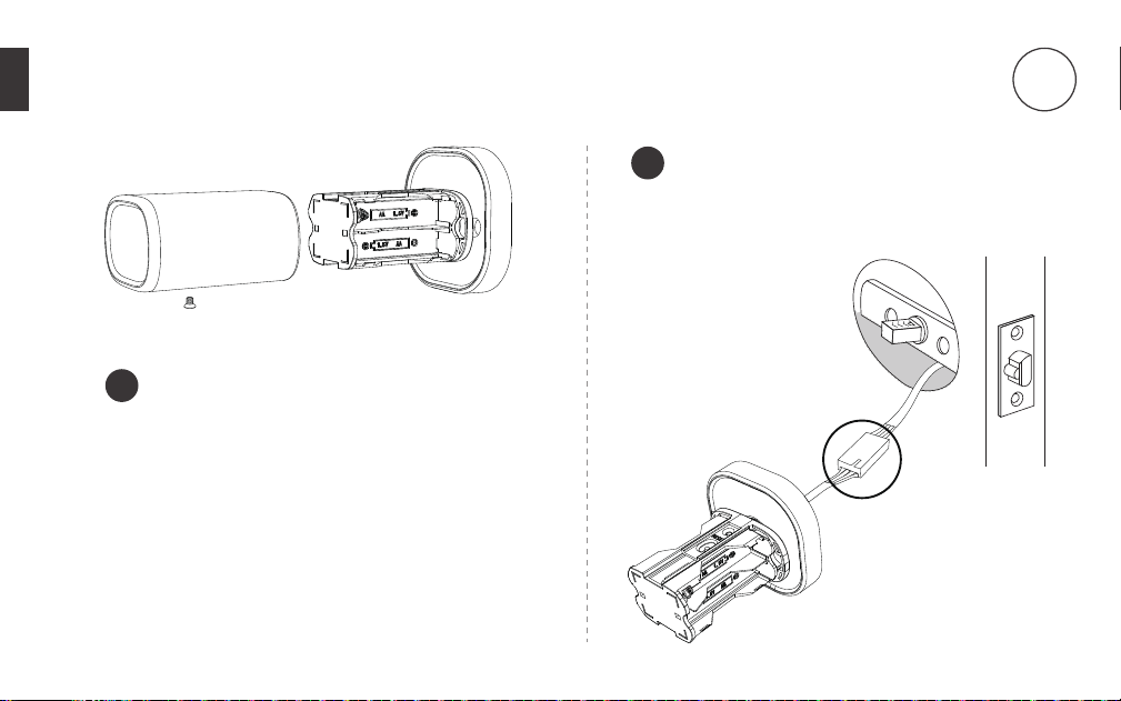
Remove the screw located at the bottom and
then pull out the cover.
Connect the control wire male connector
with the female connector from the
exterior assembly.
1
2
14
Install the Interior Assembly
4
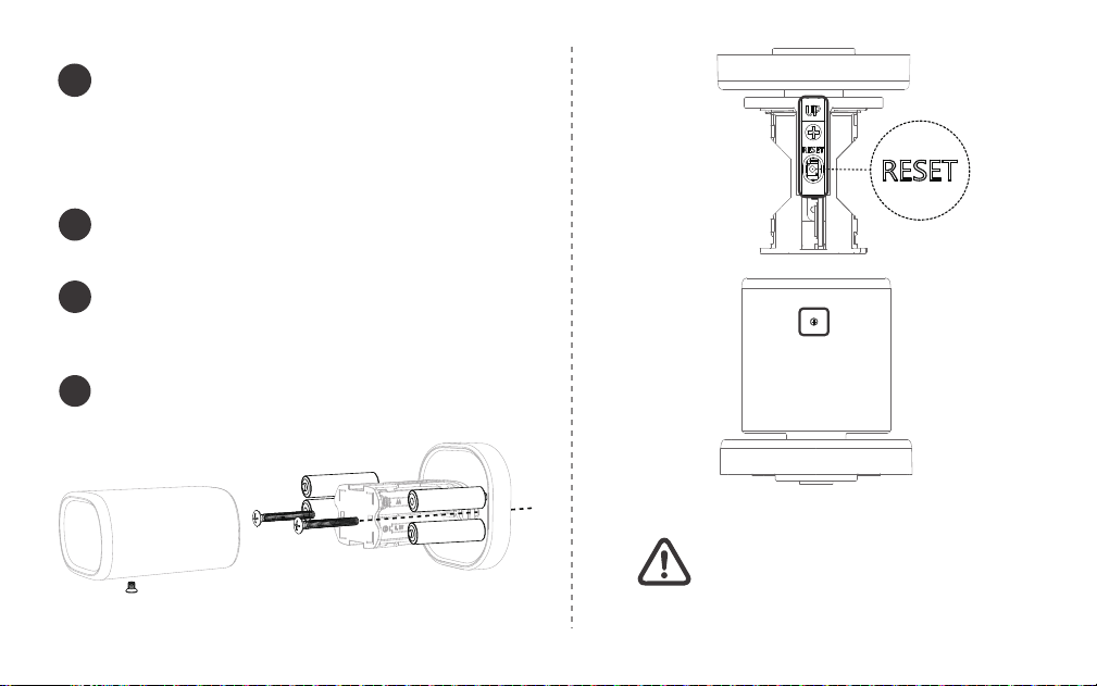
Make sure the side with the screw
faces toward the floor, or the
opposite side with the reset button
faces up.
Secure both exterior and interior knobs to
the door using the 1-2/5” (35mm) screws.
Tighten them with a Phillips Screwdriver
( DO NOT over-tighten ).
Install the batteries into the compartment.
Press and hold the reset button until you hear a
long beep.
Install and then secure the cover with the screw.
3
15
4
5
6
Top Side Facing Upward
Bottom Side Facing Floor
Note:
Make sure the door knob has been reset successfully.
If you forget your passcode and your fingerprint is
not recognized nor setup, the only way to unlock
is to use backup keys.
If you happen to lose your backup keys at the
same time, please immediately contact a locksmith
for assistance.
Testing door knob
Congratulations!
MK1 is ready for use.
16
Always test with door open.
Make sure both the interior and exterior knobs are
not slanted.
Use keys to test the exterior knob. Insert the key
and then turn it counter-clockwise 90°. And then
When you turn the knob either way, the bolt
should smoothly move in and out.
Test the interior knob. The bolt should move
smoothly in and out.
Close the door to make sure the bolt fits in the hole
on jamb.
5
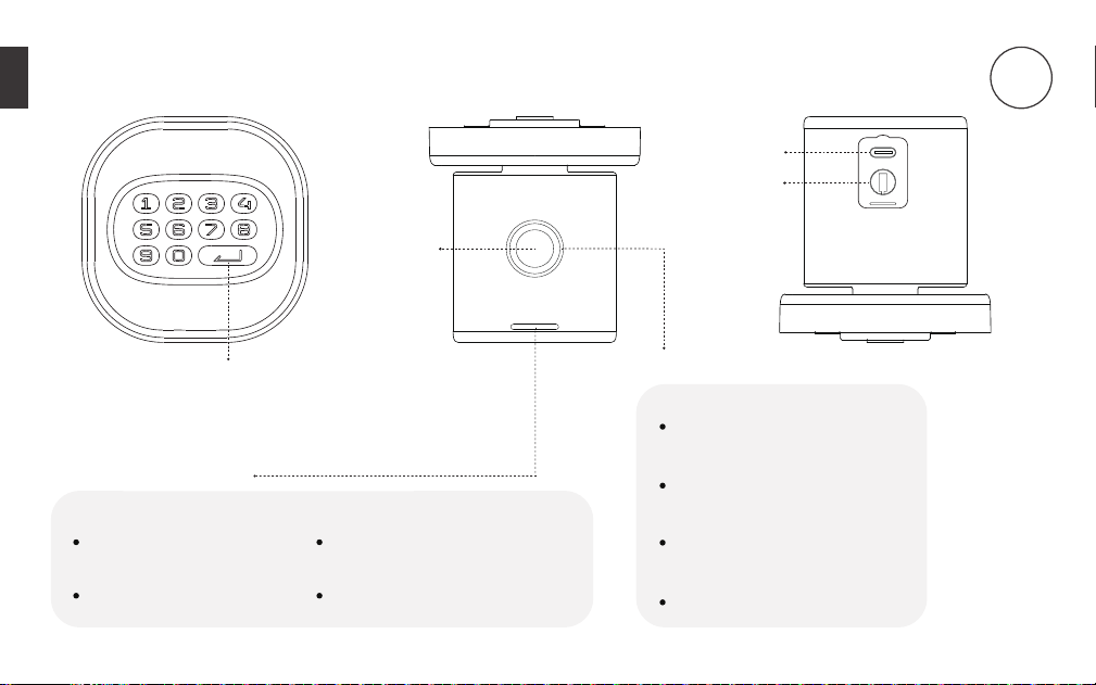
Enter button
USB-C Port
Green
Indicates a setting is
successful and activated
Unlocking successful
Status Indicator light
Fingerprint Ring light
Green
Fingerprint read successfully
White
Initialzing fingerprint sensor
Blue
Reading Fingerprint
Red
Fingerprint reading failed
17
Fingerprint
Sensor
Red
Indicates a setting is
unsuccessful and deactivated
Low-battery warning
Using door knob
6
Key Hole
18
7
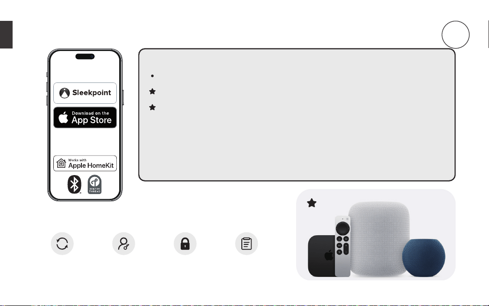
Pairing your door knob to your iOS device
Compatibility
iPhone/iPad with the latest version of iOS strongly recommended.
For best result, the door knob should be within 30 feet of one of the
Thread-enabled Apple Home hubs, or a router node (Full Thread Device) for
remote capability.
Requires a Thread-enabled Apple Home hub to use Thread network.
Firmware
Update
Lock
Activity
Manage
Access
Lock /
Unlock
DOWNLOAD
Make sure to pair your door knob within 10 minutes after resetting.
Otherwise you will need to factory reset your door knob again to
enter Pairing Mode.
If the batteries die due to long idle time, use
type-C cable with a power source such as a power
bank for emergency power. As soon as unlocking
is successful, immediately replace with new
batteries.
19
Important Tips
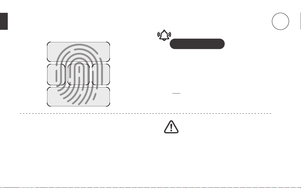
Lift and rest your finger on the fingerprint sensor
repeatedly for 6 times.
For best results, it is highly recommended to scan
the five fingerprint areas and follow the 6-step
sequence demonstrated on the left when you
add and scan a fingerprint.
Recording fingerprint ID
8
1+2
3 4
5
6
Batteries
This lock requires 4 AA Alkaline batteries from a
single brand (Duracell or Energizer recommended)
to be purchased separately. For best result, 1.2V
rechargeable batteries are NOT recommended.
When all 4 batteries are installed in the correct
position, you will hear a long beep and the indicator
lights will illuminate.

Buzzer and Status Indicator
20
Beeps twice Blinks red twice
Action Buzzer Indicator
Power on Long beep Stays green for a while
Press a button Beeps once Blinks green once
Unlocking successful Long beep Stays green for a while
Locking successful Long beep Stays green for a while
Silent mode on Silent Stays green for a while
Silent mode o Long beep Stays green for a while
Auto-Lock completed Silent O
Immediate Lock completed Long beep Stays green for a while
Resetting successful Long beep Stays green for a while
Operation failed Beeps twice Blinks red twice
Low batteries warning Beeps 5 times Blinks red 5 times
Press a button when keys
are locked up
21
Access management
To setup HomeKit Guest Access, please go to the Home app.
For full management options, please go to the Sleekpoint app.
Resetting the Door Knob/
Entering Pairing Mode
Remove the screw and cover from the interior assembly.
Press and hold the Reset Button until you hear a long beep sound along
with the green light, and then the door knob will reboot itself until you
hear another long beep sound along with green light, indicating the
reset is successful. Meanwhile, the pairing mode is activated for adding
the device to HomeKit. Make sure to pair your door knob within 10
minutes after resetting. Otherwise you will need to factory reset your
door knob again to enter Pairing Mode.
Settings
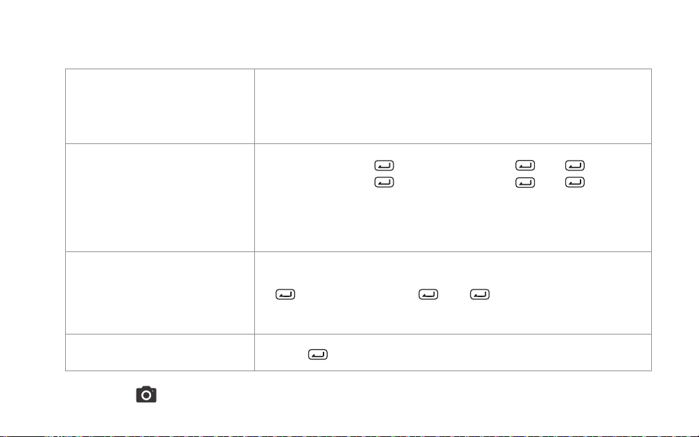
In-app Auto-Lock Settings: The door knob will automatically lock after
set time in the Sleekpoint app.
Press to lock immediately.
Turn on Auto-Lock: > unlimited passcode > > 4 >
Turn o Auto-Lock: > unlimited passcode > > 5 >
22
SAVE THESE IMPORTANT INSTRUCTIONS FOR EASY REFERENCE.
You may turn on silent mode to deactivate the buzzer.
Turn on/o Silent Mode (Buzzer)
> unlimited passcode > > 6 >
Anti-Peep
The Anti-Peep technology is used for protecting your passcode from
prying eyes. You may enter up to 20 digits including your passcode to
unlock the door knob.
Auto-Lock
Silent Mode
Immediate locking

23
Troubleshooting
No indicator nor sound
response from pressing
a button
1. Remove the cover from the interior assembly and then check if the
cable wire is securely attached. If not, remove the connector and
then plug in again.
2. Make sure the batteries are inserted properly (correct polarity).
3. Make sure the batteries have enough power.
4. Check if the door knob is in Silent Mode.
If you are stuck outside and not able to access battery
compartment, use USB-C emergency power to power
on the door knob.
Latch will not extend or
retract completely when
closed
1. Check the size of the hole in the door edge and adjust according
to installation guide.
2. Check if the latch is installed properly according to the backset
length.
3. Make sure the thinner edge of both the interior and exterior knobs
heads downward and vertically to the floor.

24
Bolt is not able to go
through the strike plate
1. Make sure the bolt aligns with the strike plate.
2. Make sure the bolt edge can slide into the strike plate.
3. Make sure depth of the hole in door jamb fits the bolt.
Failed to unlock
1. Go to access management in app and double-check if the
passcode entered is correct or fingerprint ID is properly recorded.
2. Check if the buttons work properly: Turn o Silent Mode, and
then press each button. You should hear the buzzer every time.
3. Reset the door knob, pair it to the network and then setup again.
Failed to lock or unlock/
Failed to fully turn the
knob
1. Check if the screws are overtightened when installing the interior
piece.
2. Check if both knobs are slanted from the door edge.
3. Make sure the battery level is high and no mixing of new
batteries with the old ones.

25
CAUTION:
Prevent unauthorized entry. Since anyone with
access to the interior assembly can factory reset
the door knob, routinely check the administrator
code to ensure they have not been altered without
your knowledge.
WARNING:
This Manufacturer advises that no lock can provide
complete security by itself. This lock may be defeated
by forcible or technical means, or evaded by entry
elsewhere on the property. No lock can substitute
for caution, awareness of your environment, and
common sense. Builder's hardware is available in
multiple performance grades to suit the application.
In order to enhance security and reduce risk, you
should consult a qualified locksmith or other security
professional.
Replace batteries immediately as soon as you
are warned.
Important safeguard
9
If a fingerprint or passcode is no longer needed,
please promptly remove it. If you are uncertain
about the fingerprints recorded in the past, it is
recommended to delete all fingerprints or reset
this lock.
When sending a user code, always double-check
that you are sending it to the correct recipient.
Dispose of used batteries according to local laws
and regulations.
Always have access to your lock's standard key.
Prevent water and liquids from getting into the
lock’s electric parts or battery compartment.

26
FCC WARNNINGS
10
This device complies with part 15 of the FCC Rules. Operation is subject to the following two conditions: (1)
This device may not cause harmful interference, and (2) this device must accept any interference received,
including interference that may cause undesired operation. Note: This equipment has been tested and found
to comply with the limits for a Class B digital device, pursuant to part 15 of the FCC Rules. These limits are designed
to provide reasonable protection against harmful interference in a residential installation. This equipment generates,
uses and can radiate radio frequency energy and, if not installed and used in accordance with the instructions, may
cause harmful interference to radio communications. However, there is no guarantee that interference will not occur
in a particular installation. If this equipment does cause harmful interference to radio or television reception, which
can be determined by turning the equipment off and on, the user is encouraged to try to correct the interference by
one or more of the following measures:
Warning: Changes or modifications made to this device not expressly approved by ThorBolt may void the FCC
authorization to operate this device. Note: The manufacturer is not responsible for any radio or TV interference
caused by unauthorized modifications to this equipment. Such modifications could void the user’s authority to
operate the equipment.
Contains FCC ID: 2A6C1-BB840FS
Reorient or relocate the receiving antenna.
Increase the separation between the equipment and receiver.
Connect the equipment into an outlet on a circuit different from that to which the receiver is connected.
Consult the dealer or an experienced radio/TV technician for help.