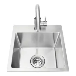
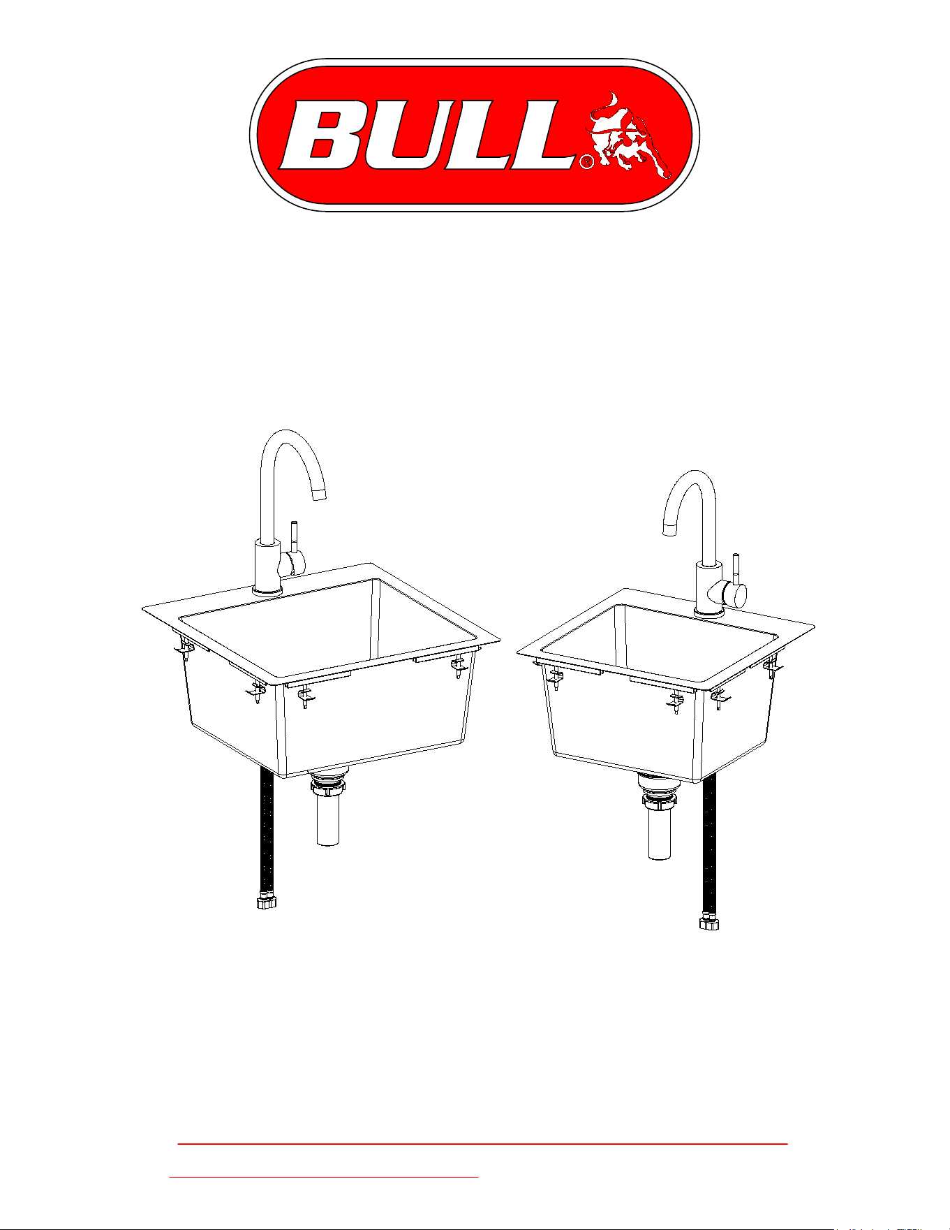
18" Dual Mount Sink
Model # 12515
15" Dual Mount Sink
Model # 12516
Stainless Steel
Sinks
v.2023.11.16
-Warning: For freezing climates faucet must be
winterized see page 13.
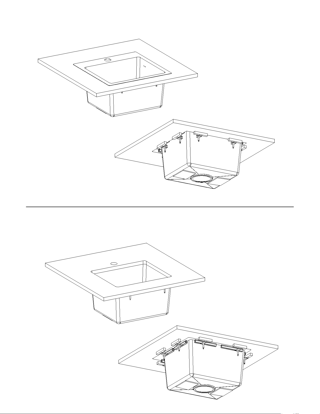
DROP IN SINK
UNDERMOUNT SINK

TABLE OF CONTENTS
Package Contents...............................................1
Hardware Contents.............................................2
Tools...................................................................3
12515 18" Dual Mount Sink (Top Mount Cut Out)...4
12516 15" Dual Mount Sink (Top Mount Cut Out)...5
Top Mount Installation........................................6
12515 18" Dual Mount Sink (Undermount Cut Out)..9
12515 18" Dual Mount Sink (Undermount Cut Out).10
Undermount Installation......... ..........................11
Care and Maintenance......................................13
Troubleshooting................................................14
Replacement Parts List.....................................15
Warranty Policy.................................................16
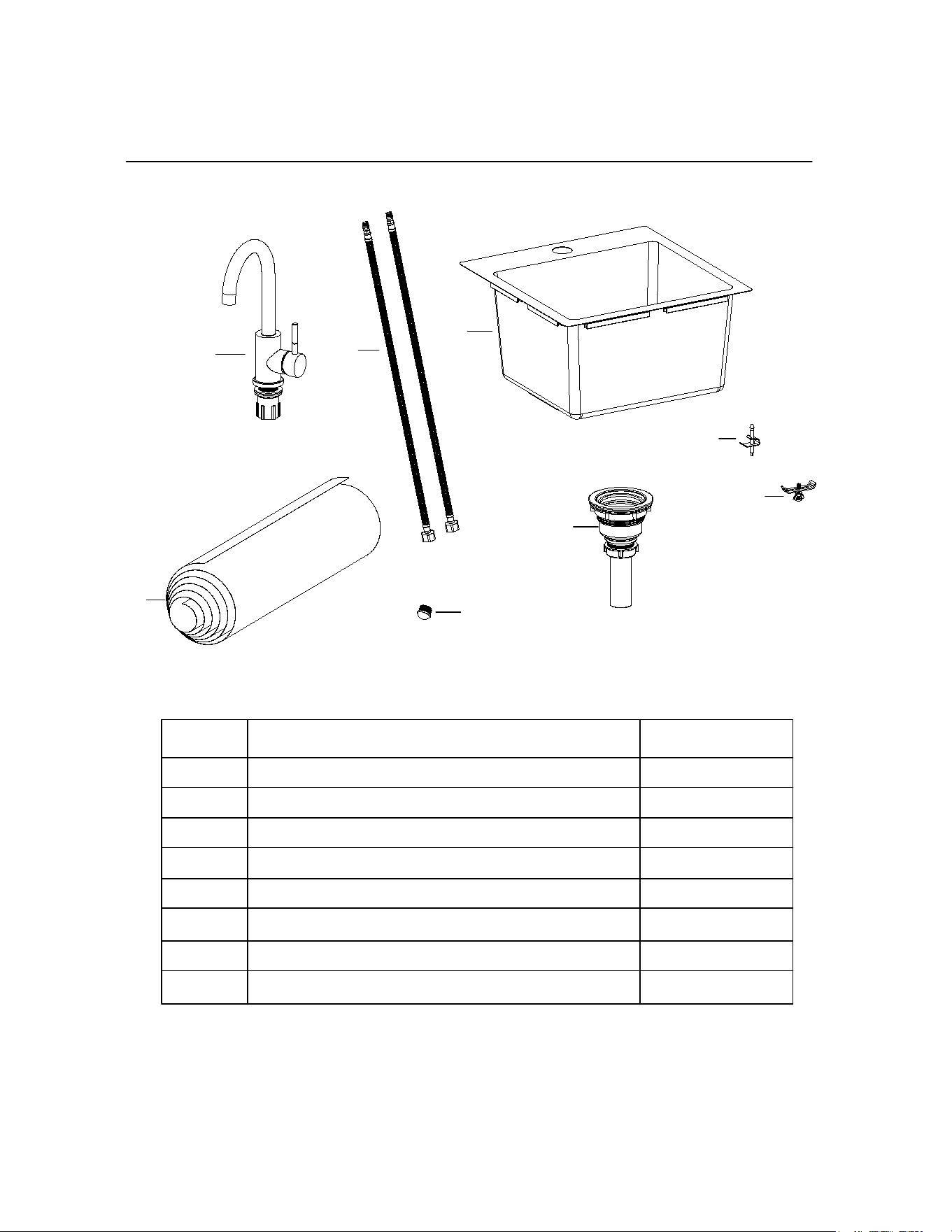
PACKAGE CONTENTS
A
B
C
D
F
PART DESCIPTION QUANTITY
A 12515 or 12516 Sink 1
B 12515 or 12516 Faucet Head 1
C Drain Assembly 1
D Top Mount Clip 8
E Undermount Clip 8
F Top and Undermount Templates 1 Set
G Braided Flexible Supply Hoses 1 Pair
H Plug for Hot Water Supply 1
E
page 1
G
H
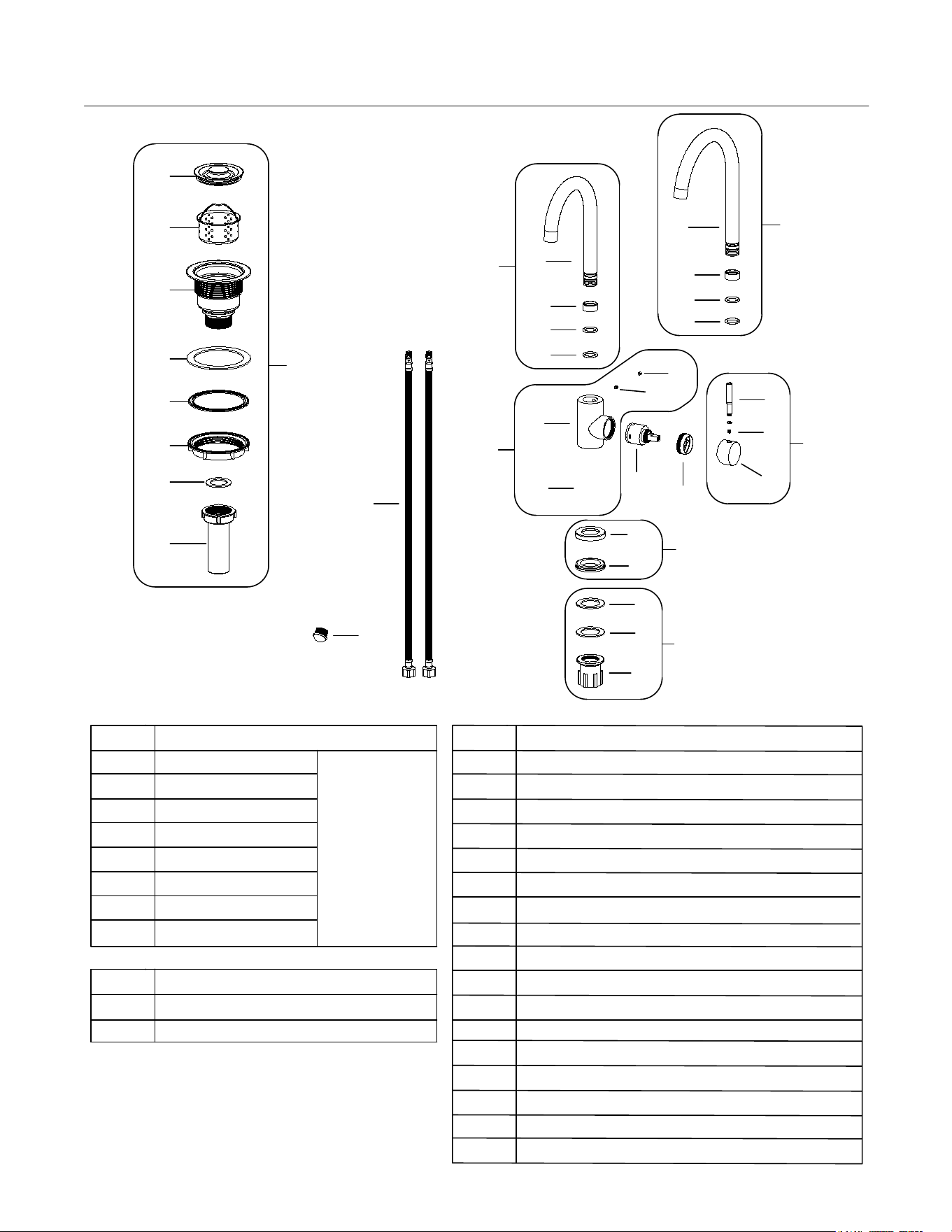
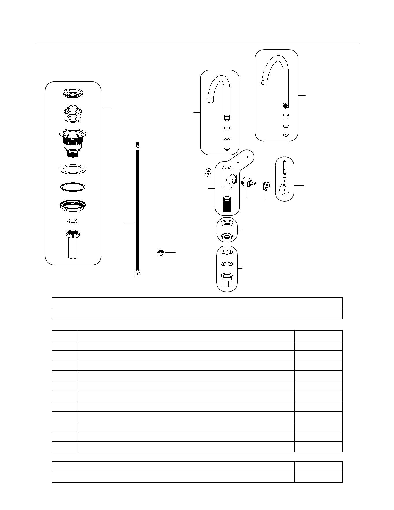
Parts List
C
D
E
F
I
K
L
O
S
W
X
Y
Drain
Water Supply Hoses
PART DESCRIPTION
A Drain Cap
B Strainer
C Bowl
D Foam Washer
E Rubber Washer
F Bowl Lock Nut
G Drain Washer
H Drain Pipe
A
B
G
H
PART DESCRIPTION
I Water Supply Hose (x2)
J Plug for Water Supply Hose
PART DESCRIPTION
K Faucet Head for 15" Sink #12516
L Faucet Head for 18" Sink #12515
M Plastic Locking Spacer
N Rubber O-Ring
O Faucet Body
P Threaded Shank
Q Set Screw
R Rubber Plug
S Faucet Cartridge
T Cartridge Lock Nut
U Cartridge Cap
V Handle
W Escutcheon plate
X Escutcheon O-ring
Y Rubber Washer
Z Washer
ZZ Hand Nut
page 2
ZZ
Drain
Assembly
Kit
Drain
Kit
Set
Set
J
T
U
Q
V
Set
Z
Q
M
N
N
M
N
N
R
P
Set
Set
Set
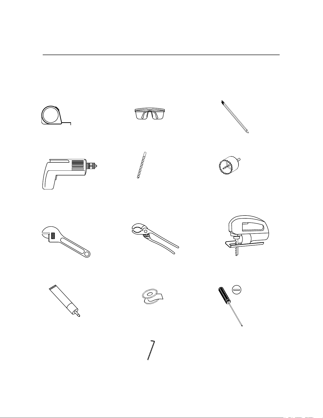
TOOLS REQUIRED FOR INSTALLATION
Note: Specialized tools may be required to install sink to countertop surfaces
other than wood or wood composited.
Measuring
Tape
Safety
Goggles
Pencil
2.5MM
Allen Key
Power Drill
Ø3MM",
Ø10MM"
Drill Bits
Jig Saw
Flathead
Screwdriver
Wrenches
Channel
Locks
Silicone
Sealant
Teflon
Tape
page 3
Ø1-3/8"
or
Ø35MM
Hole Saw
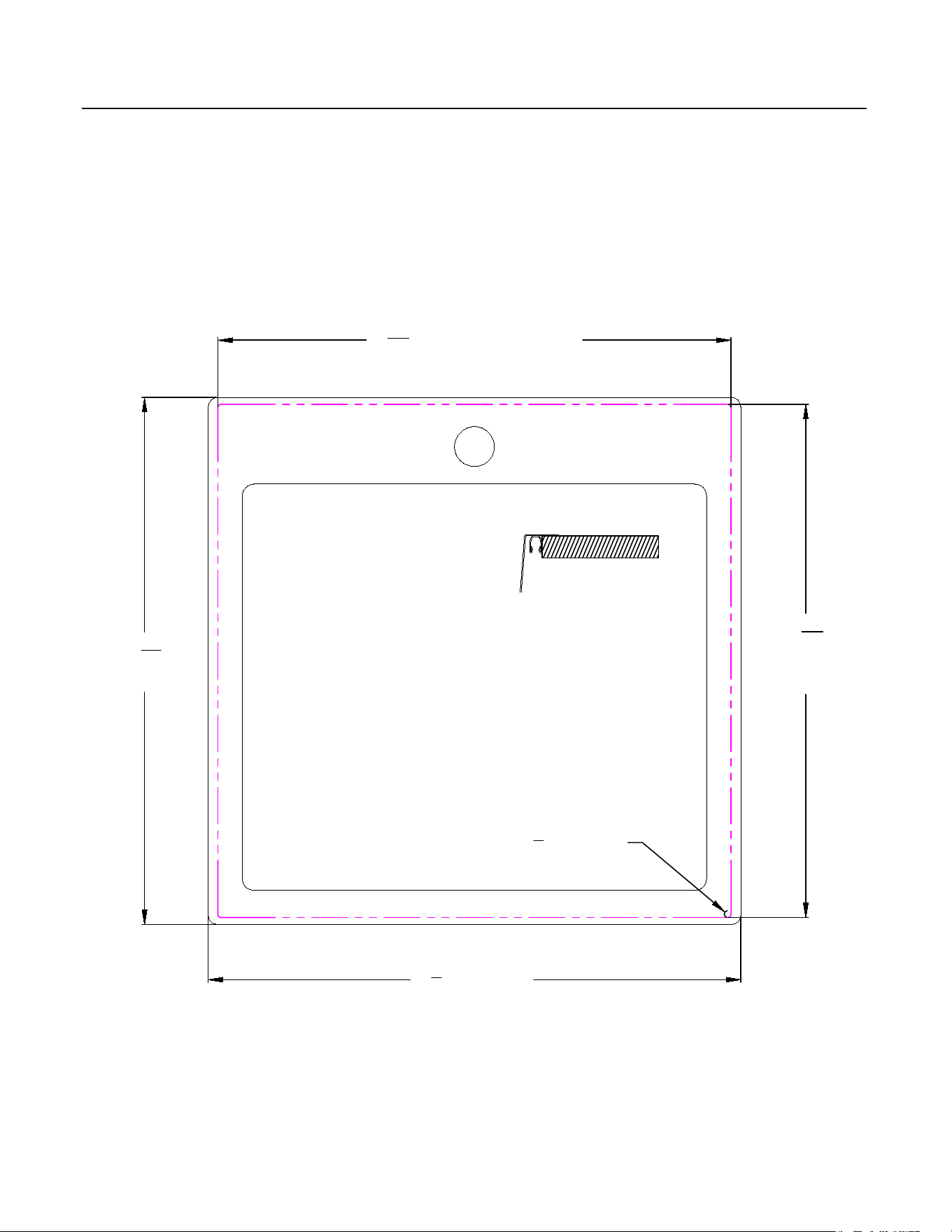
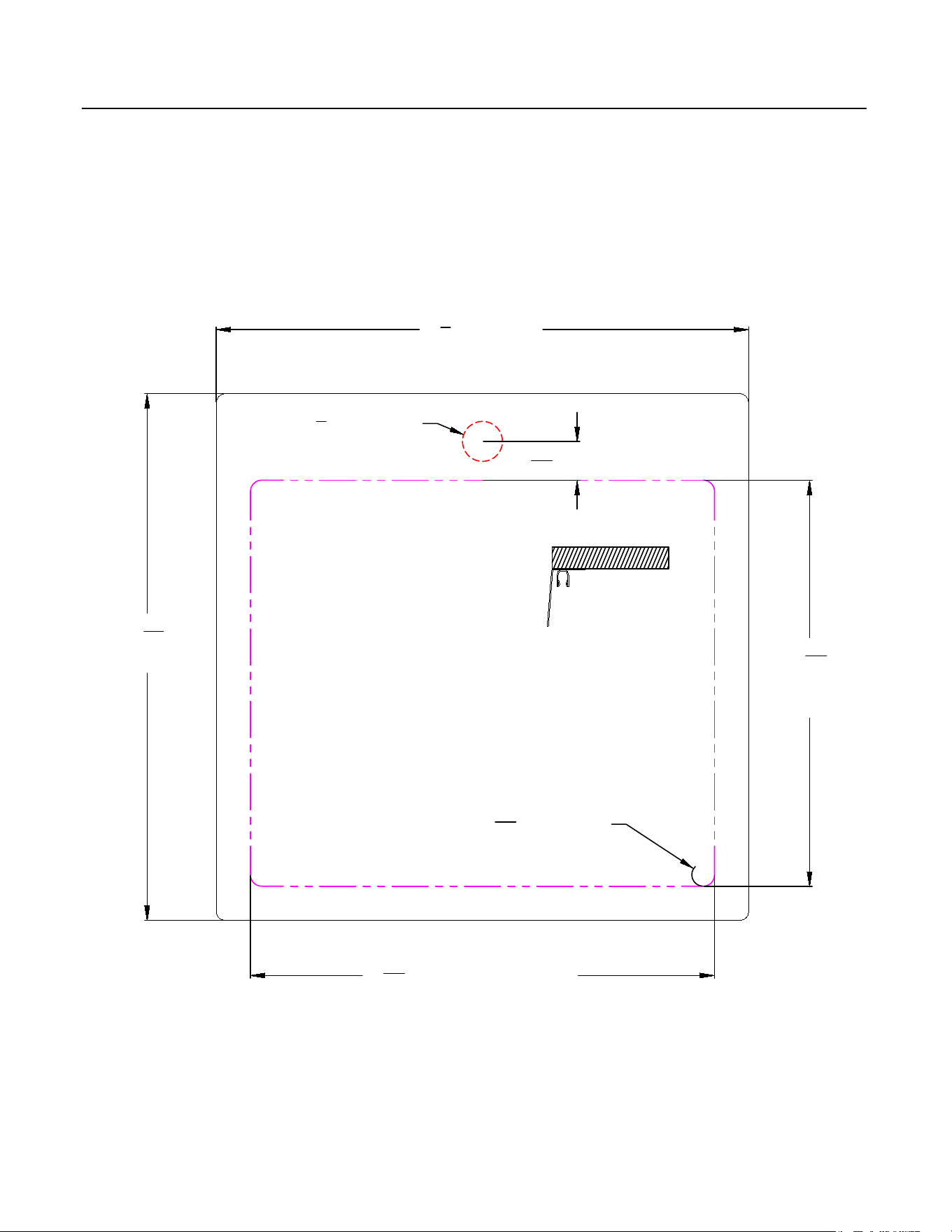
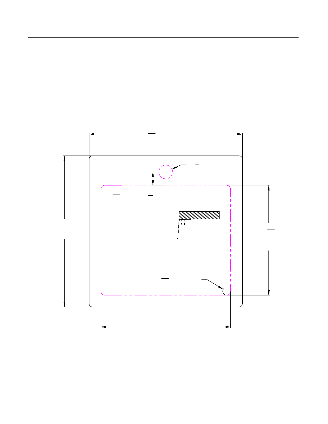
Top Mount Sink Cut Outs
Bull 18" Dual Mount Sink
Model # 12515
Cardboard Template Provided
page 4
Top Mount
18
3
16
"
[462MM]
18
3
8
" [467MM]
17
23
32
" [450MM] Cut Line
17
23
32
"
[450MM]
Cut Line
R
1
8
" [R3MM]
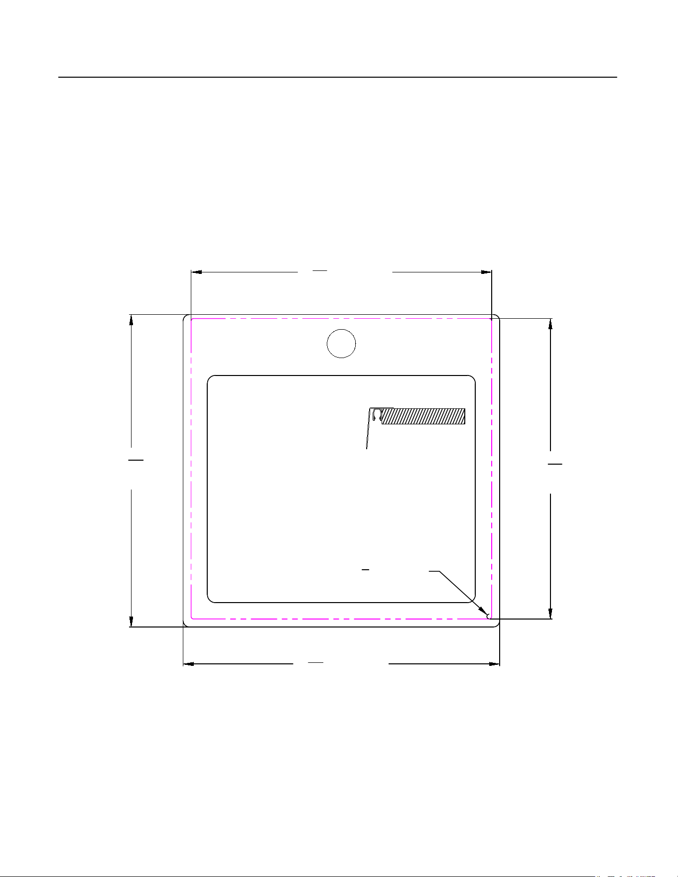
Top Mount Sink Cut Outs
Bull 15" Dual Mount Sink
Cardboard Template Provided
Model # 12516
Top Mount
14
9
16
" [370MM]
15
5
32
"
[385MM]
15
11
32
" [390MM]
14
9
16
"
[370MM]
R
1
8
" [R3MM]
page 5
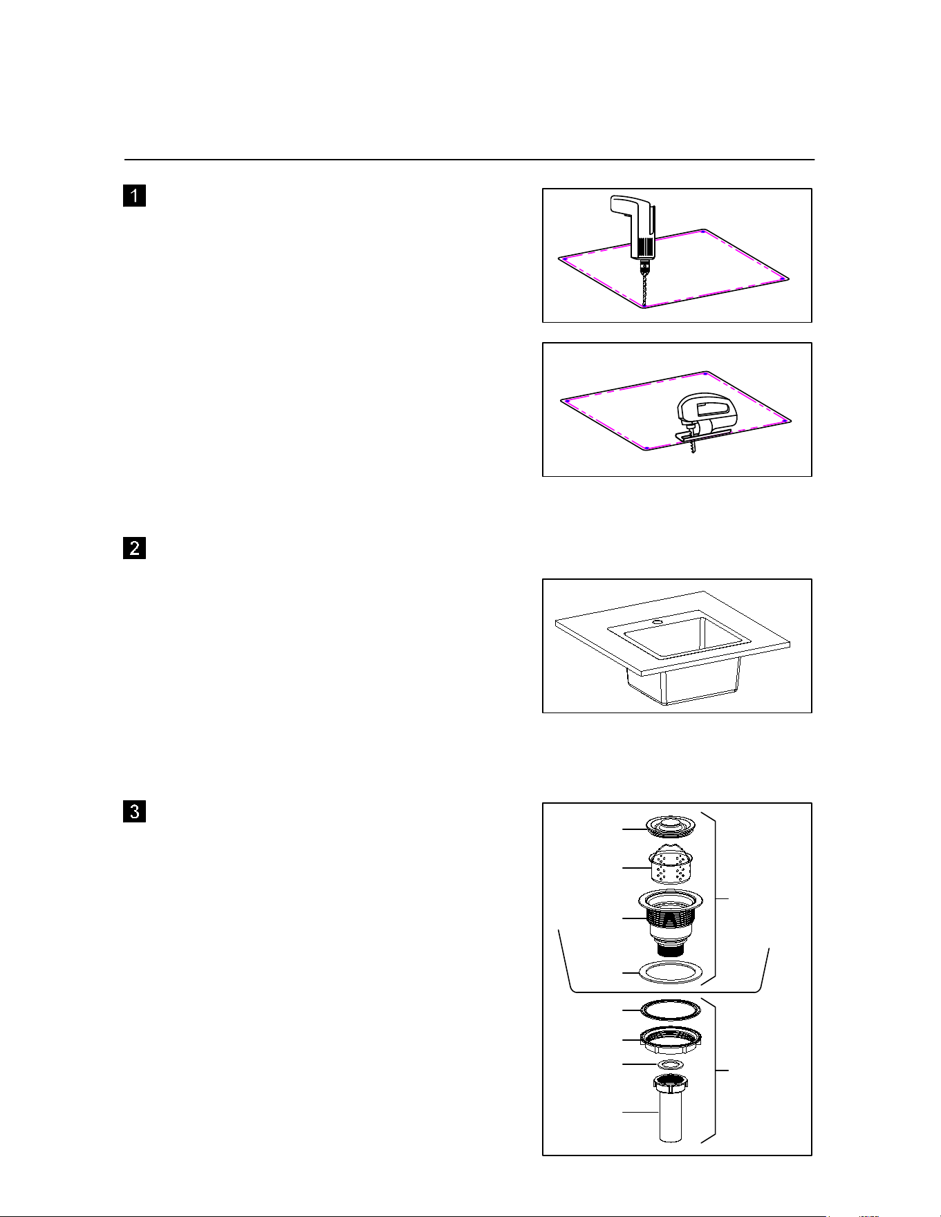
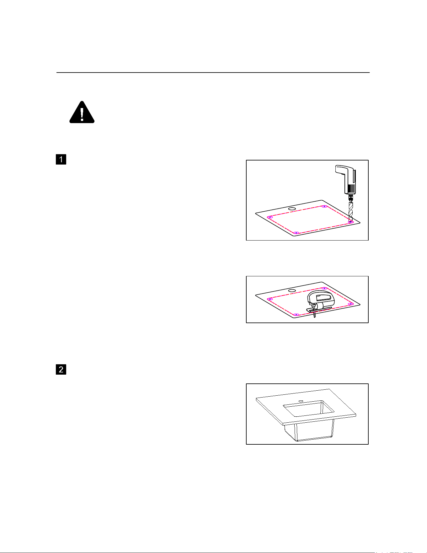
TOP MOUNT INSTALLATION
PREPARING THE COUNTER TOP
Make sure there are no obstructions such as
cabinets, plumbing, ect. below or above the
countertop.
Place template on countertop checking to
make sure the sink will line up correctly with
plumbing,
To begin the cutout for the sink, drill a
Ø6MM hole and use a jig saw to carefully
cut along the template or pencil line.
CHECK CUTOUT DIMENSIONS
Check the countertop cutout opening by
placing the sink in the opening to be sure it
is sized properly. The rim of the sink must
be set uniformly on the countertop to ensure
the corners of the sink seat properly. If sink
does not fit adjust the cutout opening using
the saber saw.
PREPARING THE STRAINER
Install the strainer as shown. It is easier to
install the strainer assembly to the sink
before the sink is installed to the cabinet.
C
D
E
F
A
B
G
H
Below
Sink
Top
Side
of
Sink
page 6
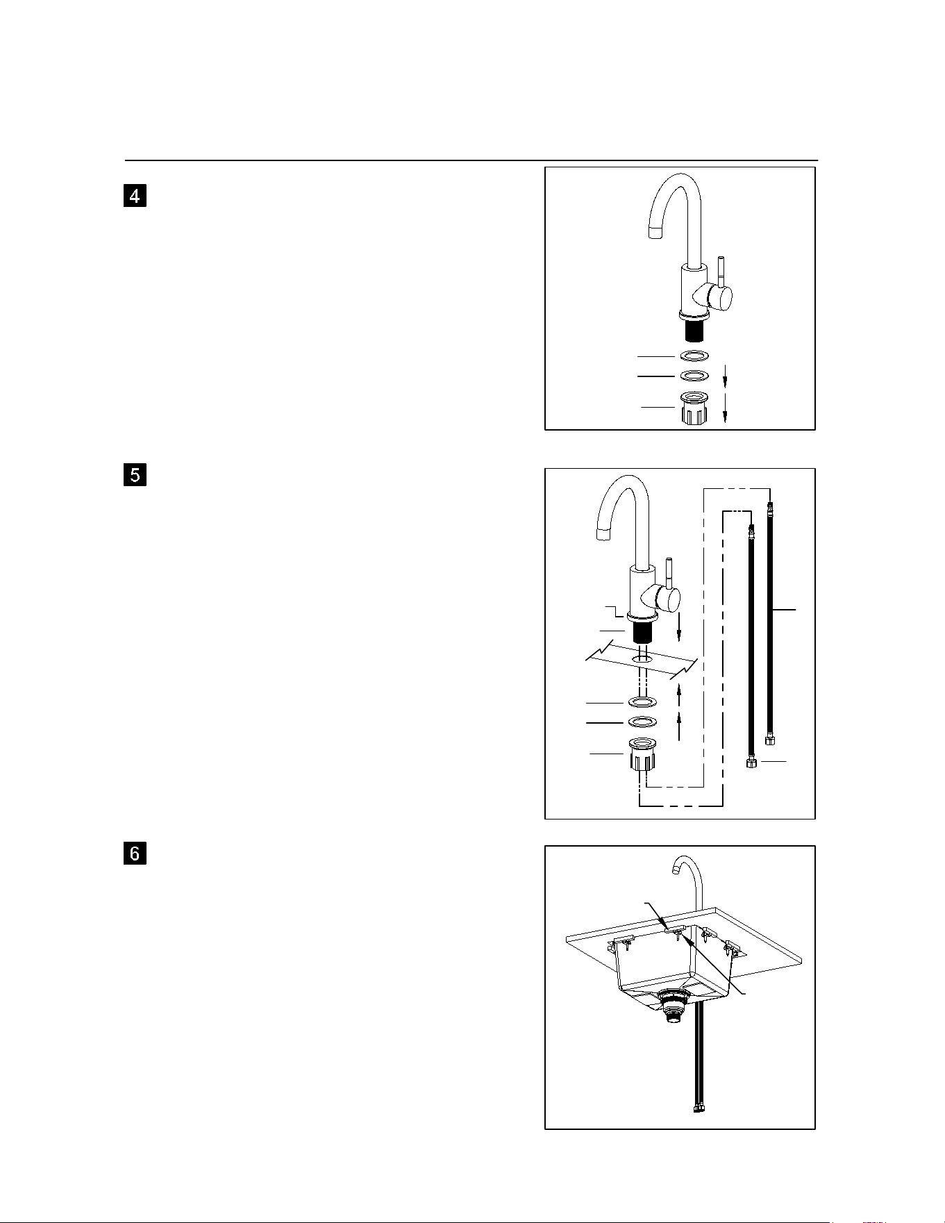
TOP MOUNT INSTALLATION (Continued)
PREPARING THE FAUCET ASSEMBLY
Remove the hand nut (ZZ), washer (Z) and
rubber washer (Y) from the threaded shank
of the faucet body.
SECURING THE FAUCET ASSEMBLY
Position the faucet in order on the sink as
shown. Slide the eschution plate (W) and
the eschution seal (X) on the threaded
shank (P) of the faucet body. Move the
assembly thru the sink faucet hole. Then
slide on the rubber washer (Y),washer (Z)
and screw on the hand nut (ZZ). Screw on
the hot and cold braided hoses (I).
I
I
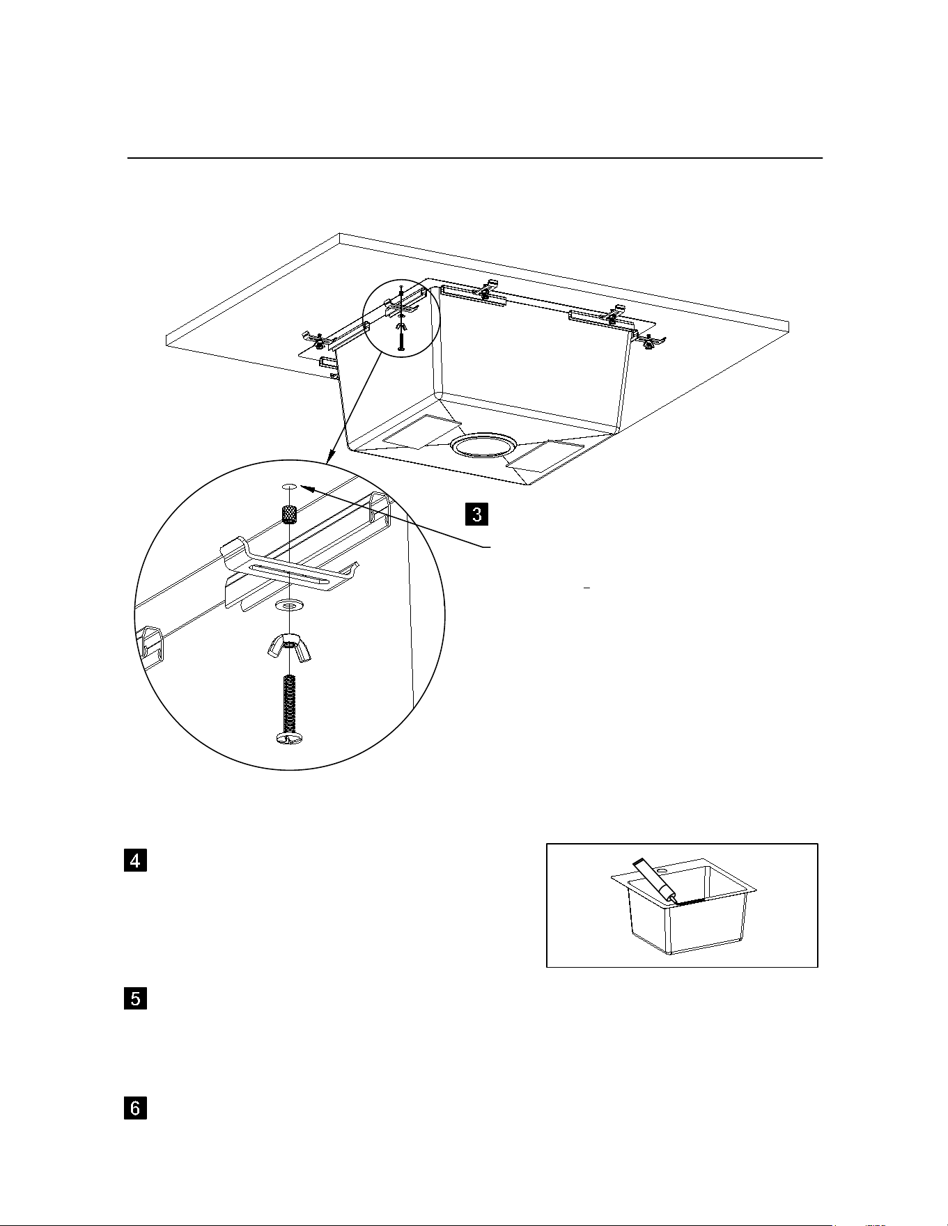
INSTALLING THE SINK
-Apply silicone sealant around the underside
lip of the sink.
-Carefully lower the sink into the counter.
-Attach the mounting clips and scrap wood
blocks .
-Tighten screws evenly until sink is flush
with counter top.
-Wipe up excess silicone with clean rag.
Wood Blocks
Mounting
Clips
page 7
Y
ZZ
Z
Y
ZZ
Z
W,X
P
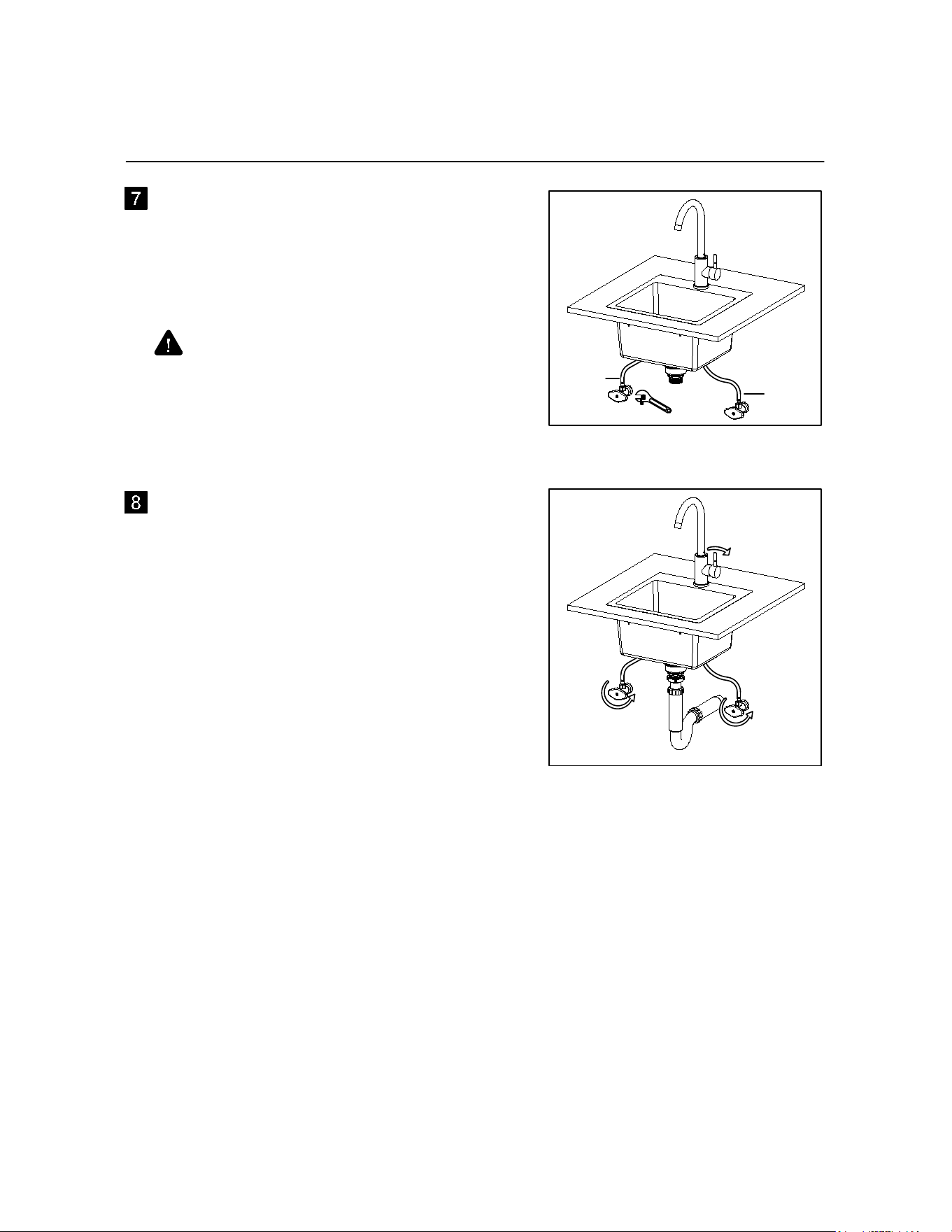
TOP MOUNT INSTALLATION (Continued)
MAKE THE WATER SUPPLY
CONNECTIONS
Connect the flexible braided hoses (I & J) to
water supply valves (not supplied) and
tighten with wrench.
Red
Stripe
Hot
Water
Cold
Water
DON'T OVER TIGHTEN!
Caution: make sure to connect the hot (red
stripe) and cold (blue stripe) water hoses to
the correct supplies.
CHECKING AND TESTING
-Before testing, connect the rest of the drain
system.
-Open the hot and cold water supplies and
look for leaks.
-Open the faucet handle and look for leaks
in the drain.
-Test for hot and cold water flowing.
-Run for a while to clear lines of air and
debree.
-Turn water off when complete
Red
Stripe
Blue
Stripe
Blue
Stripe
page 8
Undermount Sink Cut Outs
page 9
Under Mount
18
3
16
"
[462MM]
16
1
32
" [407MM] Cut Line
14
1
32
"
[356MM]
Cut Line
Ø1
3
8
" [Ø35MM]
18
3
8
" [467MM]
R
13
32
" [R10MM]
Bull 18" Dual Mount Sink
Model # 12515
Cardboard Template Provided
1
11
32
" [34MM]
Undermount Sink Cut Outs
page 10
Under Mount
15
11
32
" [390MM]
15
5
32
"
[385MM]
13" [330MM] Cut Line
R
13
32
" [R10MM]
11
1
32
"
[280MM]
Cut Line
Bull 15" Dual Mount Sink
Model # 12516
Cardboard Template Provided
15158-R10
1
11
32
" [34MM]
Ø1
3
8
" [Ø35MM]
UNDERMOUNT INSTALLATION
PREPARING THE COUNTER TOP
Make sure there are no obstructions such as
cabinets, plumbing, ect. below or above the
countertop.
Note: The template cut lines are designed
to flush with insides of the sink.
Place template on countertop checking to
make sure the sink will line up correctly with
plumbing,
Note: The type of drill bits or saws use the
countertop manufactures recommendations.
To begin the cutout for the sink, drill a
Ø20MM" hole and saw to carefully cut along
the template or pencil line.
Drill a Ø35MM or Ø1-3/8" hole for faucet as
located on template.
CHECK CUTOUT DIMENSIONS
Check the countertop cutout opening by
placing the sink in the opening to be sure it
is sized properly. The rim of the sink must
be set uniformly on the underside of the
countertop to ensure the corners of the sink
seat properly. If sink does not fit adjust the
cutout opening counter top manufactures
suggested techniques..
BEFORE YOU BEGIN...
CAUTION!
It is recomended to have a professional installer to preform this installation.
page 11
UNDERMOUNT INSTALLATION (Continued)
page 12
UNDER COUNTER MOUNTING KIT
The under counter clips are supplied. Use
counter top manufacture techniques to drill
6mm holes
1
3
the depth of countertop
thickness (Blind Holes). Install threaded
metal plug using countertop suppliers
recommendations.
INSTALLING FAUCET AND DRAIN
Refer to page 6 step 3 to page 7 to step 5. Next page 8 steps 7 and 8.
Apply silicone sealant all around the top of
the lip of the sink.
Position the sink to the under side of the counter top securing it into place with the supplied
clips and using wood blocks evenly applying pressure squeezing out the sealant. Wipe away
the excess sealant.
CARE AND MAINTENANCE
-Daily, regular cleaning to remove dirt and prevent staining is recomended. Use liquid dish
detergent, water and a soft household sponge.
-Mild, non-abrasive cleaners can be used with a nylon scrub pad. To ensure an uniform
appearance in a stainless steel sink surface, rinse with water and wipe down the sink with
a soft, dry cloth. Drying the sink will prevent water spots cause by time in the water.
-Remove stubborn stains from lime or calcium deposits by pouring a little warm vinegar or
vinegar based cleaner into the sink and allow it to sit for a few minutes. Rinse with clean
water and dry.
-Scratches are inevitable during your usage over time. Use a nylon pad with an iron free
abrasive polishing compound. Follow the original polish lines to blend out the scratch in a
small area. be careful not to overdo as aggressive scrubbing will result in a bright spot.
-DO NOT use strong abrasive cleaners, metal scub pads, or steel wool. These will scratch
the surface.
-DO NOT leave rubber mats or sponges inside the sink for prolonged periods of time.
-DO NOT let food with high salt content sit inside the sink. Water trapped below could lead
to stains.
-DO NOT allow chlorine bleach to sit inside a stainless steel sink for more than 1 hour.
-DO NOT allow drain cleaners to come in contact with sink surface.
-DO NOT pour paint in your sink. The chemicals in acrylic paint will react with sinks if
allowed to sit over 24 hours and will produce permanent marks. For latex based paints,
remove any residue immediately using a paint remover manufactured by the same brand.
Consult the paint remover recommendations before using on the sink. For all sinks we
recommend nail polish remover, rubbing alcohol or an acetone-based paint remover to
eliminate paint residue.
-Rust spots - Rust stains are the result of iron particles introduce by water, cookware, and
steel wool pads that react with water to create rust. Metal cleaners will remove rust spots.
-Food stains - Depending on the severity of the stain, use a bleach and water solution or
pour the bleach onto a cloth and cover the stain. Allow the bleach to sit for at least
1
2
hour
and then clean with dish detergent and water. Dry with cloth.
page 13
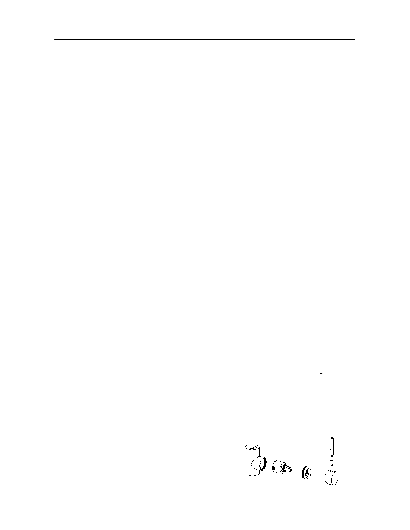
-Warning: Faucet must be winterized or it will crack
-In freezing climates water will freeze and will expand approximately 9 percent and will
crack the cartridge. The water supply needs to be turned off and the remaining water
drained and or blown out. The faucet can be taken apart for the freezing weather. Follow
the steps below.
1 - Unscrew the handle.
2 - Loosen the set screw and slide off the Cartridge cap.
3 - Unscrew the cartridge lock nut counter clockwise.
4 - Pull out the cartridge from the faucet body.
5 - Store the parts someplace to prevent freezing.
6 - Drain and or blow out the system to prevent any other possible damage.
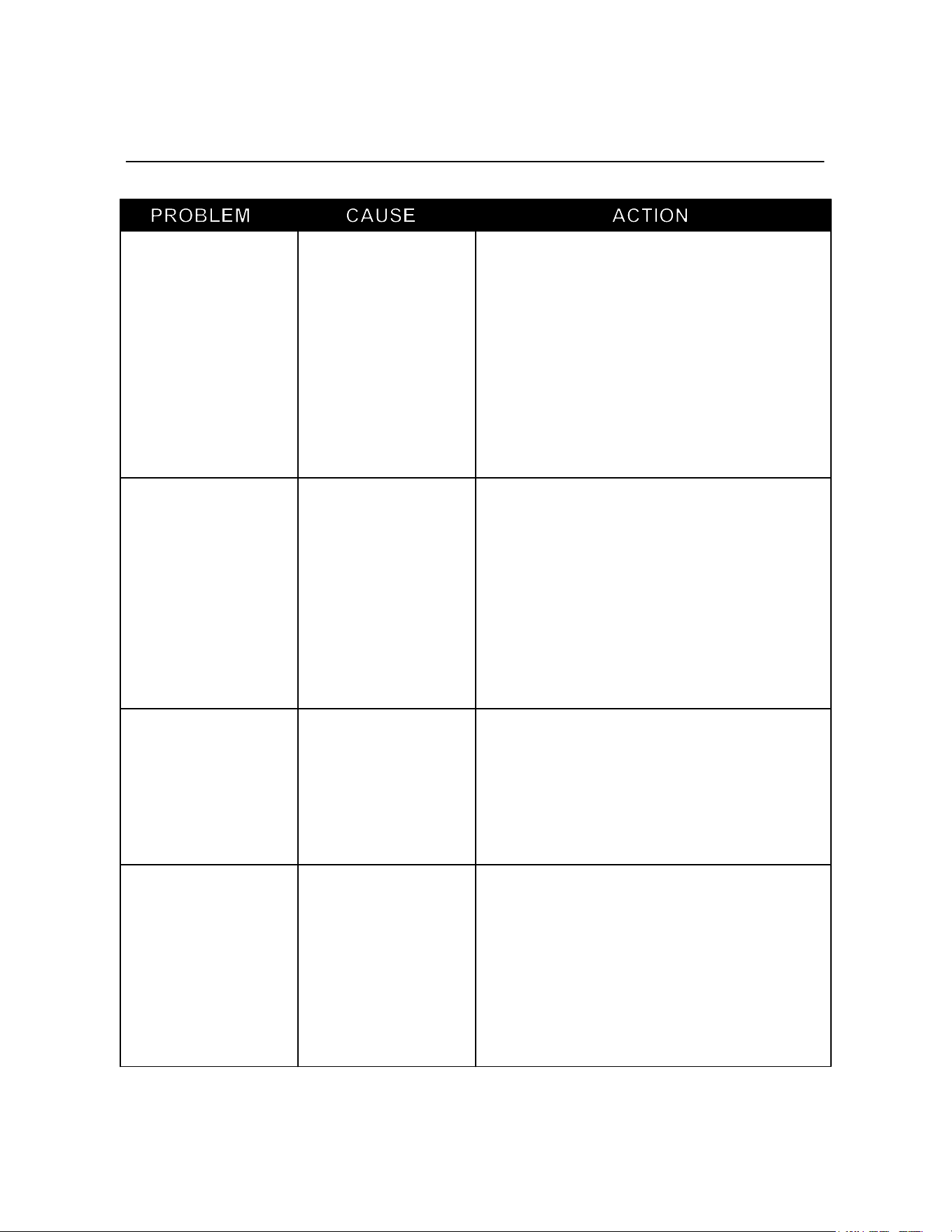
TROUBLESHOOTING FOR THE FAUCET
Leaks under the
handle assembly
page 14
The cartridge locknut
has come loose or
dirt has become
between the seals.
Seals are old and
cracked.
Turn off the water supply. Open the valve on
the faucet to relief pressure. Unscrew the
handle (S) from the cartridge cover. Use
2.5MM allen wrench and loose set screw (R)
from the hole left from the handle. Slide the
cartridge cover off (Q). Remove the cartridge
lock nut (P) by turning counter clockwise.
Remove the cartridge (O), inspect the seals
look for cracking. Make sure the faucet body is
clear of debree and dirt. Clean faucet body,
and replace cartrige if needed. Reassemble in
reverse order.
Faucet will not turn
off completely
Faulty cartridge
Turn off the water supply. Open the valve on
the faucet to relief pressure. Unscrew the
handle (S) from the cartridge cover. Use
2.5MM allen wrench and loose set screw (R)
from the hole left from the handle. Slide the
cartridge cover off (Q). Remove the cartridge
lock nut (P) by turning counter clockwise.
Remove the cartridge (O). Make sure the
faucet body is clear of debree and dirt. Clean
faucet body, and replace cartridge.
Reassemble in reverse order.
Faucet leaks below
the sink
Dirt on hose end
seats.
Bad or cracked
o-rings.
Turn off the water supply. Open the valve on
the faucet to relief pressure. Unscrew the
braided water supply hoses from faucet. Clean
the faucet hose seats. Inspect o-rings.
Replace o-rings or hose if needed.
Reassemble. Note: applying more torque to
hose does not achieve a better seal.
Hose leaks at
supply valve
Dirt on gasket.
Bad or cracked
Gasket.
Cross threaded
Turn off the water supply. Open the valve on
the faucet to relief pressure. Unscrew the
braided water supply hoses from supply valve.
Clean hose seat gasket and valve seat.
Inspect Gasket. Replace gasket if needed. If
cross threaded the hose or supply valve may
be damaged and need replacing. Reconnect
hose to supply valve. See valve manufacture
for torque specs.
Replacement Parts List
PART DESCRIPTION PART #
1 Drain Kit 12519
2 Water Supply Hose 12520
3 Water Supply Plug 12528
4 Faucet Head, seal, & O-rings for premium Sink SKU#12516 12521
5 Faucet Head, seal, & O-rings for premium Sink SKU#12515 12522
6 Replacement Faucet Body,Shank, Set Screws, & Plug 12523
7 DANCO for Glacier Bay AquaSource Item #89902 12524
8 Cartridge Lock Nut 12529
9 Cartridge Cap, Set Screw, & with Handle 12525
10 Above Counter Faucet Replacement Kit 12526
11 Under Counter Faucet Replacement Kit 12527
2
Drain
Kit
1
Water Supply Hose
3
Complete Faucet Assembly for 18" Premium Sink -SKU #12515 12517
Complete Faucet Assembly for 15" Premium Sink -SKU #12516 12518
18" Dual-Mount Premium Sink - with Stainless Steel Faucet SKU # 12515
15" Dual-Mount Premium Sink - with Stainless Steel Faucet SKU # 12516
page 15
10
Above counter faucet
replacement kit
11
Under counter faucet
replacement kit
9
Cartridge Cap
Set Screw
& Handle
4
5
6
7
8

WARRANTY POLICY
THIS LIMITED WARRANTY GIVES YOU SPECIFIC LEGAL RIGHTS. YOU MAY ALSO HAVE
OTHER RIGHTS, WHICH VARY FROM STATE TO STATE.
THIS LIMITED WARRANTY CAN ALSO BE FOUND ON OUR WEB SITE AT:
https://www.bullbbq.com/support-warranty (United States Customers);
https://www.bullbbq.eu/en/warrantyform.htm (International Customers) AND IN THE
OWNER’S/INSTALLATION MANUAL THAT WE PROVIDE WITH OUR PRODUCT.
THIS LIMITED WARRANTY IS SUBJECT TO THE EXCLUSIONS, CONDITIONS AND
LIMITATIONS
SET FORTH BELOW.
ANY IMPLIED WARRANTIES IMPOSED BY LAW, INCLUDING WITHOUT LIMITATION THE
IMPLIED WARRANTIES OF MRECHANTABILITY AND FITNESS FOR A PARTICULAR PURPOSE,
ARE LIMITED IN DURATION TO THE DURATION OF THIS EXPRESS LIMITED WARRANTY.
SOME STATES DO NOT ALLOW LIMITATIONS ON HOW LONG AN IMPLIED WARRANTY
LASTS,
SO THE ABOVE LIMITATION MAY NOT APPLY TO YOU.
WHO MAY USE THIS WARRANTY?
BULL OUTDOOR PRODUCTS, INC. located at address 1011 East Pine St. Lodi, CA. 95240
("we") extend this limited warranty only to the consumer who originally purchased the product
("you") at the original site of delivery or installation. It does not extend to any subsequent owner or
other transferee of the product. It does not apply to products installed in any rental, commercial or
non-residential application. Examples of excluded applications include, but are not limited to day
care centers, schools, bed and breakfast centers, churches, private clubs, fire stations, club houses,
common areas in multi-family dwellings, restaurants, hotels, nursing homes, food service locations
and institutional food service locations.
WHAT DOES THIS WARRANTY COVER?
This limited warranty covers defects in materials and workmanship of the product and product
components identified below for the Warranty Periods defined below.
WHAT IS THE PERIOD OF COVERAGE?
This limited warranty starts on the date of your purchase and lasts for the time period or time
periods specified above (the "Warranty Period"). The Warranty Period is not extended if we repair
or replace the product. We may change the availability of this limited warranty at our discretion,
but any changes will not be retroactive.
LIMITED WARRANTY ON BULL OUTDOOR PRODUCTS, INC., PRODUCTS
• Component Warranty Periods
All of the parts for our components/grill carts/refrigerators/kegerators/drawers/doors are covered
for one year with these exceptions:
WHAT DOES THIS WARRANTY NOT COVER?
This limited warranty does not cover any damage due to: (a) transportation; (b) storage; (c)
improper installation or use; (d) use on improper fuel/gas supply; (e) failure to follow the product
instructions or to perform any preventive maintenance; (f) modifications; (g) unauthorized repair;
(h) normal wear and tear; or (i) external causes such as accidents, abuse, or other actions or events
beyond our reasonable control.
page 16

WARRANTY POLICY CONTINUED
page 17
WHAT ARE YOUR REMEDIES UNDER THIS WARRANTY?
With respect to any defective product claim made during the Warranty Period, we will, in our sole
discretion, either: repair or replace such product (or the defective part) free of charge or (b) refund
the purchase price of such product. We will not pay for shipping charges for repaired or
replacement parts, or for any labor or labor related charges. We will not pay for any accessory
products or ancillary products purchased by you for use in connection with the product.
HOW DO YOU OBTAIN WARRANTY SERVICE?
To obtain warranty service, you must submit a warranty claim online through the Bullbq.com
website during the Warranty Period. Warranty claims will not be accepted via email, fax or phone.
LIMITATION OF LIABILITY
THE REMEDIES DESCRIBED ABOVE ARE YOUR SOLE AND EXCLUSIVE REMEDIES AND OUR
ENTIRE LIABILITY FOR ANY BREACH OF THIS LIMITED WARRANTY. OUR LIABILITY SHALL
UNDER NO CIRCUMSTANCES EXCEED THE ACTUAL AMOUNT PAID BY YOU FOR THE
DEFECTIVE PRODUCT, NOR SHALL WE UNDER ANY CIRCUMSTANCES BE LIABLE FOR ANY
CONSEQUENTIAL, INCIDENTAL, SPECIAL OR PUNITIVE DAMAGES OR LOSSES, WHETHER
DIRECT OR INDIRECT.
SOME STATES DO NOT ALLOW THE EXCLUSION OR LIMITATION OF INCIDENTAL OR
CONSEQUENTIAL DAMAGES, SO THE ABOVE LIMITATION OR EXCLUSION MAY NOT APPLY
TO YOU.
Revised 10-15-2020 APR