© 2024 TP-Link 7106511364 REV7.1.0
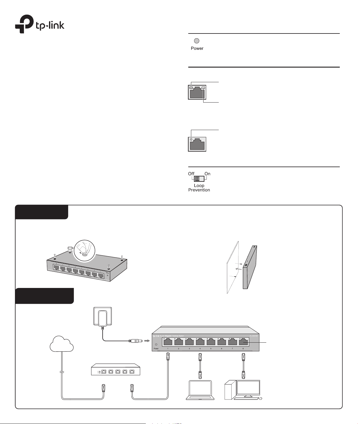
On: Power on
O: Power o
Flashing: Loop occurs in the network topology
Panel Explanation
Power LED
Switch
Link/Act LED
Note:
For simplicity, we will take TL-SG108 for example throughout this Guide.
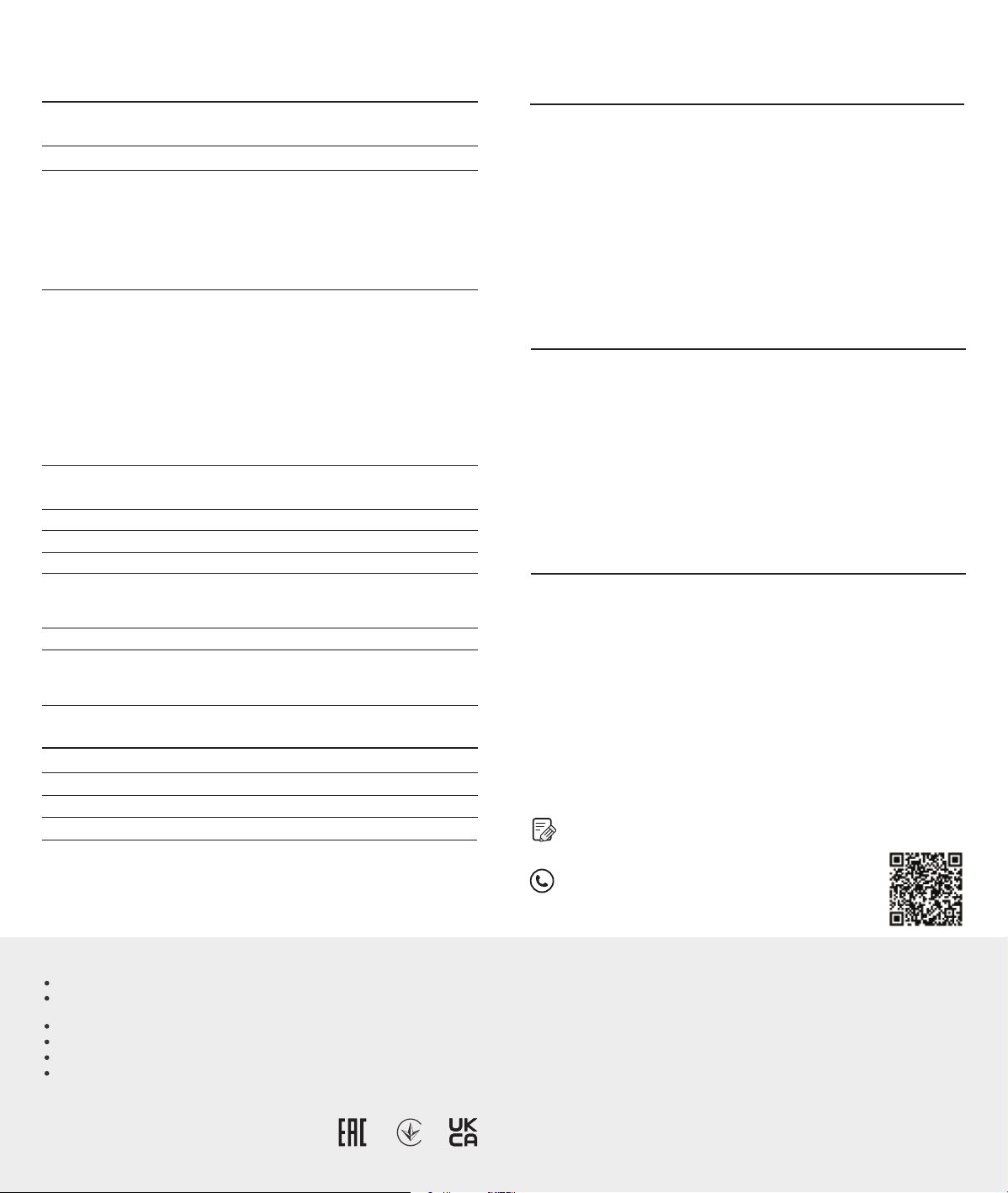
Connection
Ethernet Ports (1-8)
PC
PC
Router
LAN PortWAN Port
Internet
TL-SG108
Power Adapter
Link/Act
On: Running at 10/100/1000 Mbps
O: No device is linked to the corresponding port
Quick ashing: Transmitting/receiving data
Slow ashing: Loop is detected on the corresponding port
On: The switch will monitor and address loop-related
issues within the network structure to prevent disruptions
caused by redundant pathing
O: (default) The switch will not try to monitor or address
loop-related issues
Installation Guide
5/8/16-Port Gigabit Desktop Switch
1000M (Green)
On: Running at 1000 Mbps
10/100M (Yellow)
On: Running at 10/100 Mbps
Flashing: Transmitting/receiving data
Flashing: Transmitting/receiving data
For TL-SG116:
For other models:
Installation
Desktop:
Attach the supplied feet to the bottom of the switch to prevent it from slipping
when placed on a desktop.
Note: For detailed information, please refer
to the Wall Mounting Guide on the device’s
support page.
Wall-mounting:
Drill two holes on the wall according to the mounting holes on the bottom of
the switch, then secure the switch to the wall with two suitable screws (not
provided).
Operating Temperature
Storage Temperature
Operating Humidity
Storage Humidity
Environmental and Physical Specications
0 ˚C to 40 ˚C (32 ˚F to 104 ˚F)
-40 ˚C to 70 ˚C (-40 ˚F to 158 ˚F)
10% to 90%RH non-condensing
5% to 90%RH non-condensing
Q1. The Power LED is not lit.
Q2. The Link/Act LED is not lit when a device is connected
to the corresponding port.
Frequently Asked Questions (FAQ)
The Power LED should be lit when the power system is working
normally. If the Power LED is not lit, check as follows:
A1:
Make sure the power adapter is connected to the switch with
power source properly.
A2
: Make sure the voltage of the power supply meets the requirements
of the input voltage of the switch.
A3:
Make sure the power source is ON.
It is recommended that you check the following items:
A1:
Make sure that the cable connectors are rmly plugged into the
switch and the device.
A2:
Make sure the connected device is turned on and works normally.
A3:
The cable must be less than 100 meters long (328 feet).
Q3. Why does the switch fail to detect and block a loop
from occurring in the network topology when Loop
Prevention is enabled?
A:
When this switch is connected to other non-terminal devices, such
as switches of other brands, and the device is incapable of correctly
processing or forwarding loop detection packets, the Loop
Prevention function will be limited. It is recommended to connect
the terminal devices directly to this switch or connect non-terminal
devices with complete forwarding capability to this switch.
Standard
Protocol
Interface
Specications
General Specications
Data Transfer Rate
Network Media (Cable)
LED Indicators
Transfer Method
MAC Address Learning
Frame Forward Rate
Wall Mountable
Distance Between
Mounting Holes
Ye s
TL-SG105/TL-SG105S: 39 mm
TL-SG108/TL-SG108S: 94 mm
TL-SG116: 204.8 mm
10Base-T: 14881pps/Port
100Base-TX: 148810pps/Port
1000Base-T: 1488095pps/Port
IEEE802.3, IEEE802.3i, IEEE802.3u, IEEE802.3ab,
IEEE802.3x, IEEE802.1p
CSMA/CD
Ethernet:
10 Mbps (Half Duplex), 20 Mbps (Full Duplex)
Fast Ethernet:
100 Mbps (Half Duplex), 200 Mbps (Full Duplex)
Gigabit Ethernet:
2000 Mbps (Full Duplex)
10Base-T:
UTP category 3, 4, 5 cable (maximum 100 m)
EIA/TIA-568 100
Ω
STP (maximum 100 m)
100Base-TX:
UTP category 5, 5e cable (maximum 100 m)
EIA/TIA-568 100
Ω
STP (maximum 100 m)
1000Base-T:
UTP category 5e cable (maximum 100 m)
EIA/TIA-568 100 Ω STP (maximum 100 m)
5/8/16 10/100/1000 Mbps Auto-Negotiation
RJ45 Ports
Power, Link/Act LED
Store-and-Forward
Automatically learning, automatically aging
Safety Information
Do not use any other chargers than those recommended.
Keep the device away from water, re, humidity or hot environments.
Adapter shall be installed near the equipment and shall be easily accessible.
Do not use damaged charger or USB cable to charge the device.
Use only power supplies which are provided by manufacturer and in the origin
packing of this product. If you have any questions, please don’t hesitate to contact us.
Do not attempt to disassemble, repair, or modify the device. If you need service, please
contact us.
EU declaration of conformity
For TL-SG116:
TP-Link hereby declares that the device is in compliance with the essential requirements and other relevant
provisions of directives 2014/30/EU, 2014/35/EU, 2011/65/EU and (EU)2015/863.
The original EU declaration of conformity may be found at https://www.tp-link.com/en/support/ce/
For other models:
TP-Link hereby declares that the device is in compliance with the essential requirements and other relevant
provisions of directives 2014/30/EU, 2014/35/EU, 2009/125/EC, 2011/65/EU and (EU)2015/863.
The original EU declaration of conformity may be found at https://www.tp-link.com/en/support/ce/
UK declaration of conformity
TP-Link hereby declares that the device is in compliance with the essential requirements and other
relevant provisions of the Electromagnetic Compatibility Regulations 2016 and Electrical Equipment
(Safety) Regulations 2016.
The original UK declaration of conformity may be found at https://www.tp-link.com/support/ukca/
For technical support and other information, please visit
https://www.tp-link.com/support/?type=smb, or simply
scan the QR code.
To ask questions, find answers, and communicate with TP-Link users or
engineers, please visit https://community.tp-link.com/business to join
TP-Link Community.
