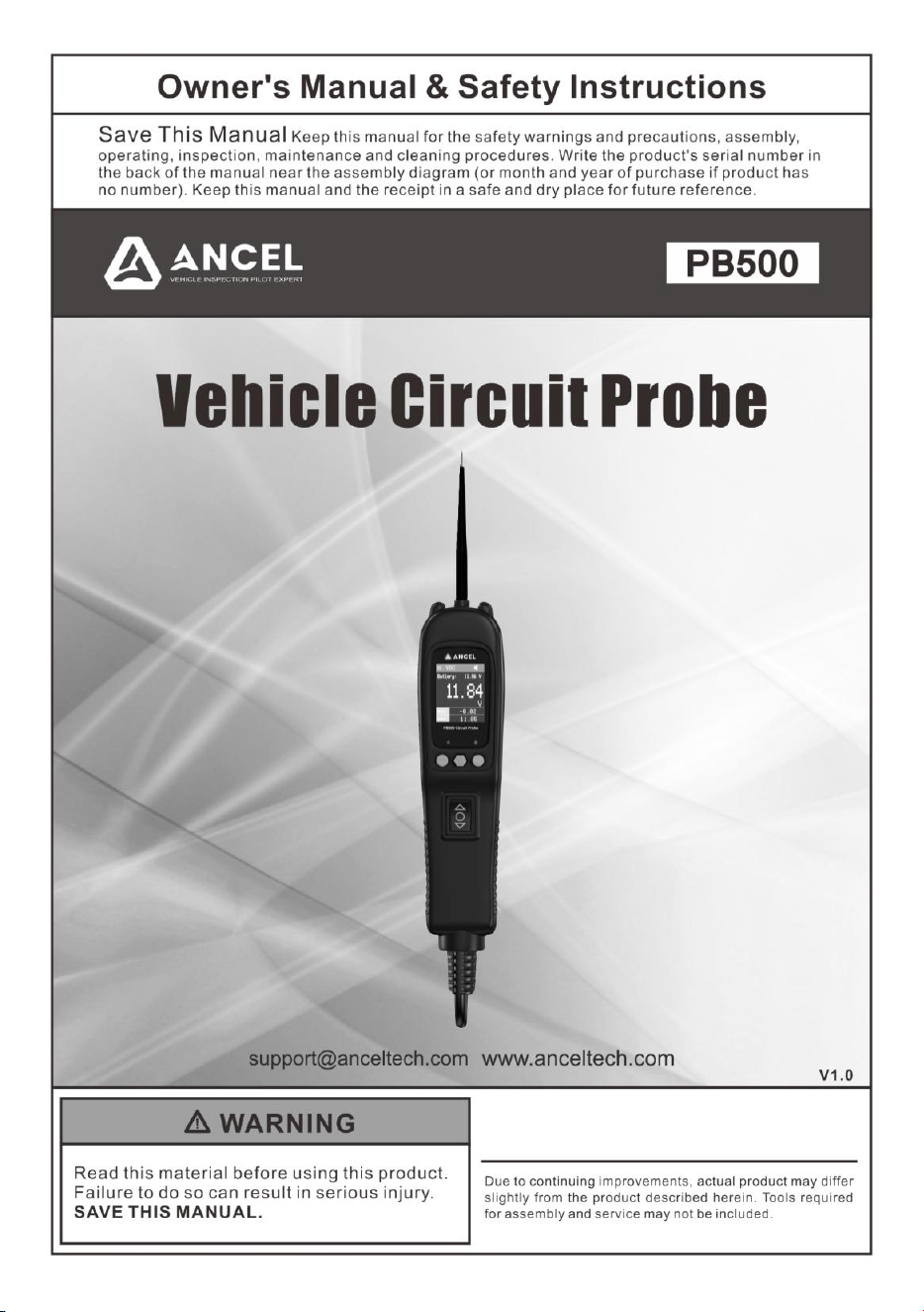

Vehicle Circuit Probe
- 1 -
Table of
Contents
1. IMPORTANT SAFETY INFORMATION......................................................2
2. PRODUCT INTRODUCTION .....................................................................3
3. PRODUCT SPECIFICATIONS ....................................................................4
4. PRODUCT APPEARANCE ….........................................................................5
5. FUNCTION INTRODUCTION ..................................................................6
5.1 DC VOLTAGE .........................................................................................7
5.2 AC VOLTAGE............................................................................................8
5.3 FREQUENCY...................................................................................9
5.4 DUTY CYCLE.......................................................... ...................10
5.5 FUEL INJECT...............................................................................................11
5.6 RESISTANCE. ........................................................................... 12
5.7 DIODE......................................................................................13
5.8 VOLTAGE & POLARITY TESTING..........................................................14
5.9 CONTINUITY TESTING.............................................................15
5.10 SIGNAL CIRCUIT TESTING.......................................................................16
5.11 ACTIVATING COMPONENTS IN YOUR HAND.........................................17
5.12 ACTIVATING COMPONENTS IN THE VEHICLE.......................................18
5.13 TESTING TRAILER LIGHTS AND CONNECTIONS.............................19
5.14 ACTIVATING COMPONENTS W/GROUND...............................................20
5.15 FOLLOWING & LOCATING SHORT CIRCUITS.........................................21
5.16 CHECKING FOR BAD GROUND CONTACTS..........................................21
6. PARTS LIST ................................................................................. 21
7. PRODUCT WARRANTY .............................................................................22

Vehicle Circuit Probe
- 2 -
1. Important Safety Information
To prevent personal injury or damage to vehicles and/or the test tool, read this
instruction manual first and observe the following safety precautions at a minimum
whenever working on a vehicle:
Always perform automotive testing in
a safe environment.
Wear safety eye protection that
meets safety standards.
Keep clothing, hair, hands, tools, test
equipment, etc. away from all
moving or hot engine parts.
Operate the vehicle in a
well-ventilated work area: Exhaust
gases are poisonous.
Put blocks in front of the drive
wheels and never leave the vehicle
unattended while running tests.
Use extreme caution when working
around the ignition coil, distributor
cap, ignition wires and spark plugs.
These components create
hazardous voltages when the engine
is running.
Put the transmission in PARK ( for
automatic transmission) or
NEUTRAL (for manual transmission)
and make sure the parking brake is
engaged.
Keep a fire extinguisher suitable for
gasoline/chemical/ electrical fires
nearby.
Don’t connect or disconnect any test
equipment while the ignition is on or
the engine is running.
Keep the tool dry and clean. Use a
mild detergent on a clean cloth to
clean the outside of the test tool,
when necessary.
When the rocker switch in the tool is
depressed battery current/voltage is
conducted directly to the tip which
may cause sparks when contacting
ground or certain circuits. Therefore
the tool should NOT be used around
flammables such as gasoline or its
vapors. The spark of an energized
tool could ignite these vapors. Use
the same caution as you would when
using an arc welder.
Warning!
PB500 is ONLY for 12-24V vehicle battery electrical systems, and should NOT be
used to test 110/220V household electric appliances; otherwise, it will be damaged.
The LED and LCD pull no more than 100 milliamp of current, therefore when using
this device as a test light or multimeter, it is safe for computer and airbag.
While performing component activation, please pay special attention: when the
instrument is powered on, if the rocker switch is pressed forward or rearward,
it means that all the battery current is being introduced from the positive or
negative pole through the probe. Please strictly follow the instructions to avoid
damage to the vehicle’s electrical component.

Vehicle Circuit Probe
- 3 -
2. Product Introduction
PB500 Can:
1. Diagnose 12 ~24V automotive electrical systems swiftly and accurately.
2. Show battery voltage reading and help user determine circuit polarity immediately
after connecting the PB500 clips to the vehicle battery.
3. Test DC Voltage, AC Voltage, Frequency, Duty Cycle, Fuel Injection Circuit,
Resistance, and Diode. Especially, in AC Voltage, Frequency, Duty Cycle and
Fuel Inject Modes, user can long press the mode button for 3 seconds to switch
between Waveform Display Mode and Digital Display Mode.
4. Activate electrical components and test their functions without jumper leads – by
depressing the rocker switch to conduct a positive or negative battery current to
the tip so as to power up electrical components.
5. Test bad ground contacts instantly without performing voltage drop tests.
6. Help user to follow and locate short circuits without using external fuses.
7. Test continuity with the assistance of its auxiliary ground lead.
8. The tool is short-circuit protected. If it becomes overloaded, Its internal circuit
breaker will trip to protect the instrument from overload.
9. When the circuit breaker is tripped, the tool will NOT be able to conduct battery
current to the tip even when the rocker switch is pressed; however, all other
functions of the tool are still active, which means you can still probe a circuit and
observe the voltage reading.

Vehicle Circuit Probe
- 4 -
3. Product Specifications
(1) Tool Specifications
Display
TFT color display (160x128 dpi )
Operating Temperature
-10 ~ +60℃ ( 14 ~ 140℉)
Storage Temperature
-20 ~ +70℃ (-4 ~ 158℉ )
Dimensions (L*W*H)
200mm*52mm*39mm
Net Weight
0.48Kg
(2) Electrical Specifications
Supply Voltage
8V DC ~ 30V DC
DC/ AC Voltage Test
-110V ~ 110V
Frequency
0Hz ~ 1Mhz
Duty Cycle
0.0~100.0%
Fuel Injection
Voltage: 0~180V, Time: 0~25ms
Resistance
0~1MΩ
Diode
Germanium diode, silicon diode
Rating Current
1A~8 A
Instrument Trip Time:
8 Amps: Hold > 1 hour.
12 Amps: current: trip in one hour.
16 Amps: current: trip in 3-30 seconds.
24 Amps: current: trip in 0.5-4.0 seconds.
Vehicle Circuit Probe
- 5 -
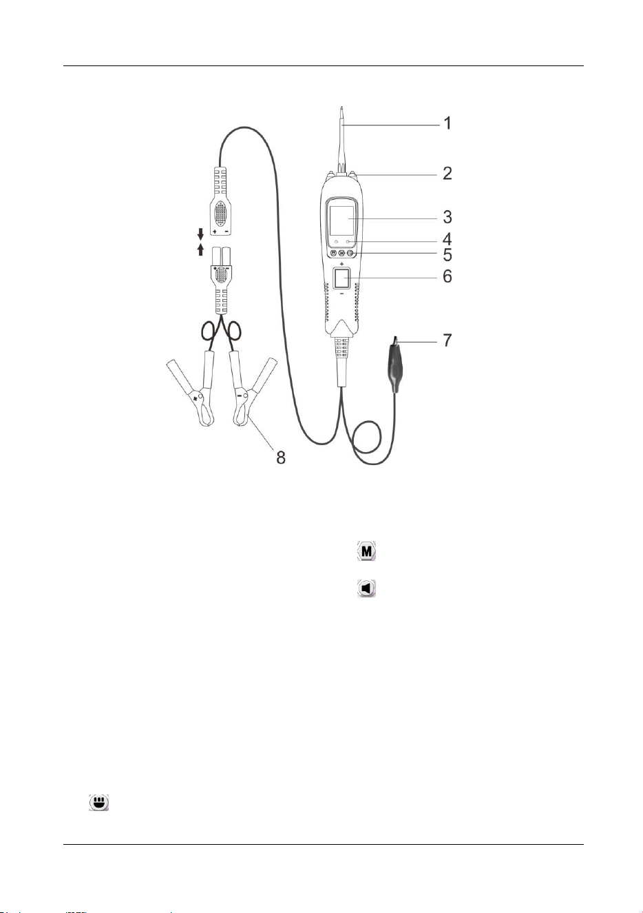
4. Product Appearance
Figure 1
1) Probe Tip - Contacts the circuit or
component to be tested.
2) LED Lights - Illuminates dark work
areas or work areas at night.
3) LCD Display - Indicates test results,
test data and waveforms.
4) Red/ Green Polarity Indicator -
Identifies positive, negative or open
circuits. The RED Indicator lights
when the Probe Tip is contacting a
positive circuit. The GREEN
Indicator lights when the probe tip is
contacting a negative or negative
voltage circuit. When the resistance
is being measured, the green
indicator light is on when the
resistance is less than 30Ω.
5) Function Button:
Switching Light ON &OFF/Up
Button - short press is the up button,
long press is to turn the light on/off;
Mode Button - for selecting test
mode;
Silent/Down Button - short
press is the down button, long press
is to turn on/off the buzzer.
6) Rocker Switch - Allows you to
conduct a positive or negative
battery current to the tip for
activating and testing the function of
electrical components.
7) Auxiliary Ground Lead - Assists
test as a ground lead.
8) Red/Black Alligator Clips - Clip the
red alligator clip to the battery
positive pole; Clip the black alligator
clip to the battery negative pole.
Vehicle Circuit Probe
- 6 -
5. Function Introduction
PB500 has 7 test modes: DC Voltage, AC Voltage, Frequency, Duty Cycle, Fuel
Injection Circuit Detection, Resistance, and Diode. Especially, in AC Voltage,
Frequency, Duty Cycle and Fuel Inject Modes, user can long press the mode button
to switch between Waveform Display Mode and Digital Display Mode. After the power
is turned on, short press the mode button to enter the menu, select the test mode by
pressing the up and down keys, and then press the mode button to enter the desired
test mode.
Before testing a circuit or component, make sure your tool is in good order by doing a
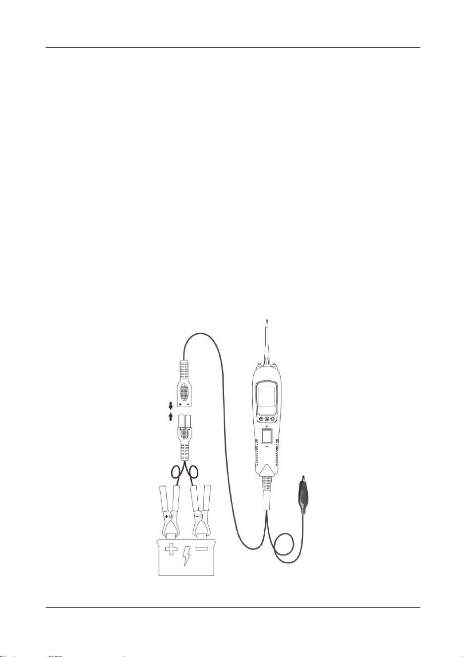
quick self-test. Connect the vehicle battery properly to turn the instrument on, the
instrument enters DC Voltage Mode by default, and the fast self-test is performed in
DC Voltage Mode. The rocker switch is an on-off switch located on the tool’s front
side. The positive and negative poles are marked above and below the switch. Press
the Rocker Switch forward to activate the tip with a positive voltage. The Red LED
should light and LCD display will read the battery voltage and tip voltage. A beep tone
will sound. Let go of the rocker switch and the LED will turn off and the tone will cease.
Press the Rocker Switch rearward to activate the tip with a negative voltage. The
Green LED should light and the LCD display will read the battery voltage and 0.0V
(ground). A beep tone will sound. Let go of the rocker switch and the LED will turn off
and the tone will cease. Your tool is working correctly and is now ready for use.
(Figure 2)
Figure 2
Vehicle Circuit Probe
- 7 -
IMPORTANT: When powering-up components, you can increase the life of rocker
switch in the tool if you first press the switch, and then contact the tip to the
component. The arcing will take place at the tip instead of the metal contacts of the
rocker switch.
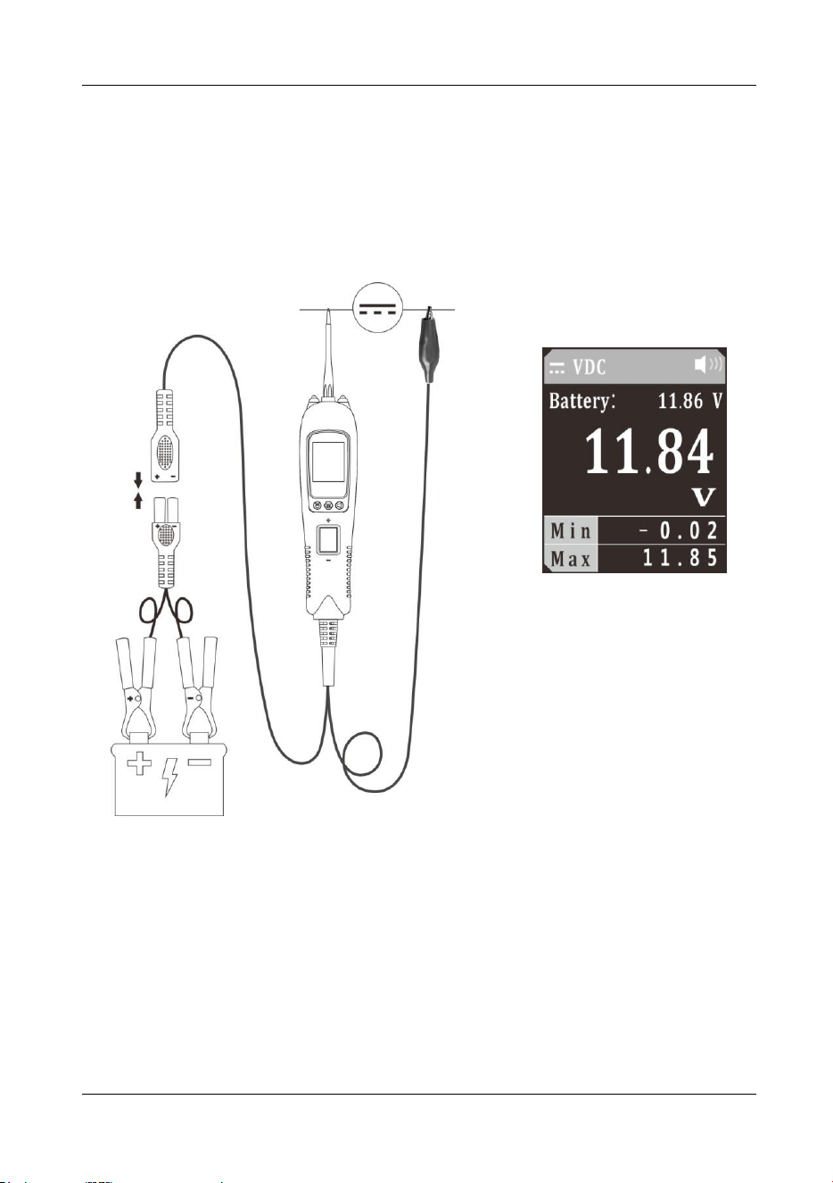
5.1 DC Voltage
Figure 3
1) Clip the red alligator clip to battery positive pole; clip the black alligator clip to
battery negative pole.
2) Contact the probe tip to the circuit.
3) The LCD display will show the battery voltage and the real-time voltage,
maximum and minimum values at the probe (Figure 3). The battery voltage
reading will not be affected and its accuracy can be assured by the application of
Kelvin test method, which avoids voltage drop usually caused by excessive length
of instrument power cable.
Vehicle Circuit Probe
- 8 -
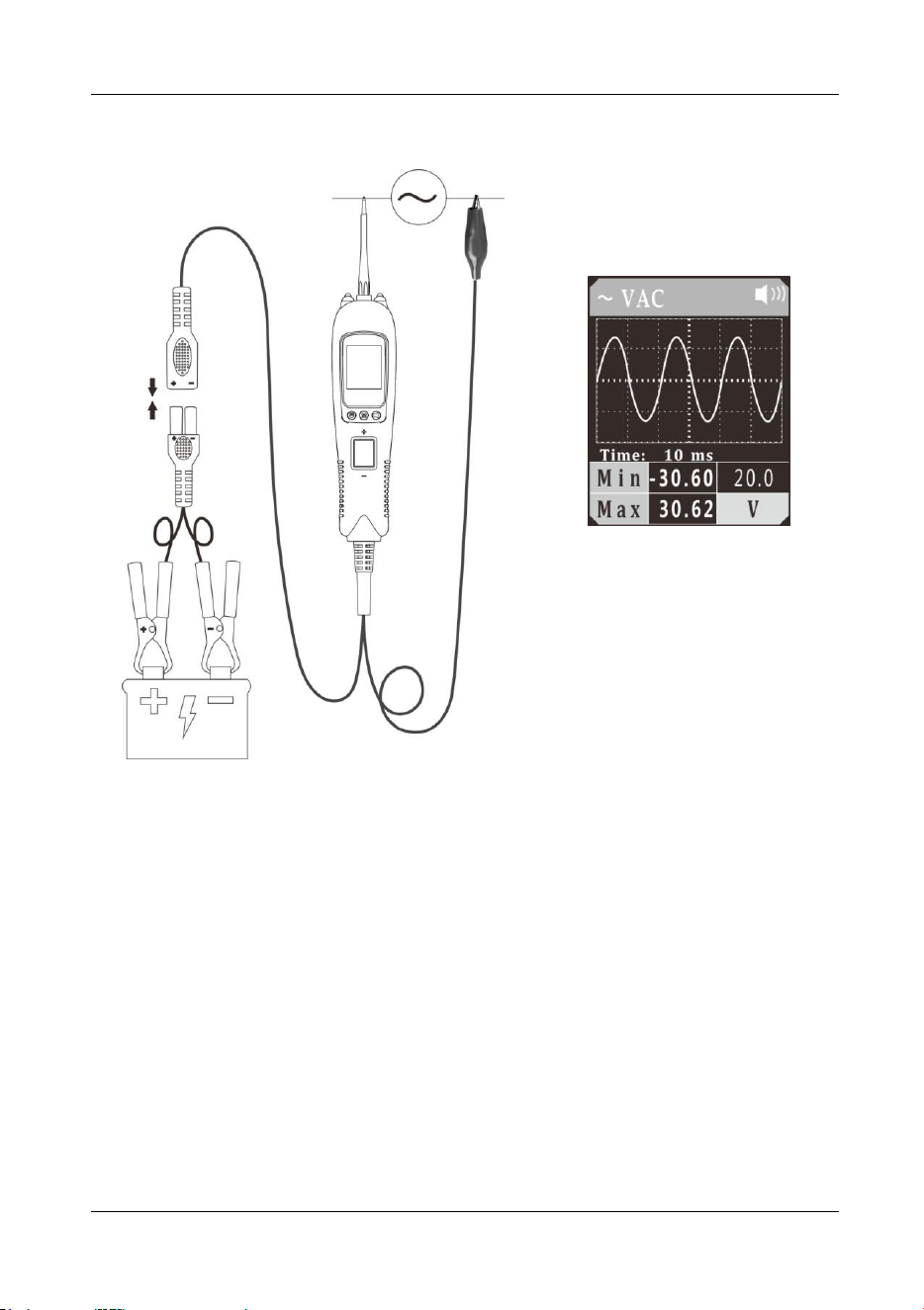
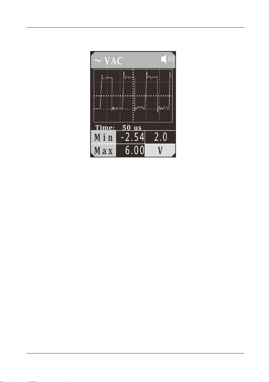
5.2 AC Voltage
Figure 4
1) Clip the red alligator clip to the battery positive pole; clip the black alligator clip to
the battery negative pole.
2) Once the device is powered on, it will enter DC voltage test mode as default.
Short press the mode button to enter the menu, short press the down button to
place the cursor in the AC voltage mode, and short press the mode button to
enter the AC voltage waveform display mode.
3) The auxiliary ground wire is connected to one end of the circuit under test, and
the probe contacts the other end of the test circuit. The LCD display will read the
maximum and minimum voltage value (Figure 4), and display the signal waveform
in real time. You can adjust the sampling frequency by pressing the Up/Down
Button.
4) In Figure 4, “time: 10 ms” is the time interval indicated by each large grid. This
time reading will change with the sampling frequency.
5) Long press and hold the mode button until the device switches to digital display
mode. The device will display the true RMS value, the minimum voltage value,
and the maximum voltage value.

Vehicle Circuit Probe
- 9 -
5.3 Frequency
Figure 5
1) Clip the red alligator clip to the battery positive pole; Clip the black alligator clip to
the battery negative pole.
2) Once the device is powered on, it will enter DC voltage test mode as default.
Short press the mode button to enter the menu, short press the down button to
place the cursor in the frequency mode, and short press the mode button to enter
the frequency waveform display mode.
3) The auxiliary ground wire is connected to one end of the circuit under test, and
the probe contacts the other end of the test circuit. The LCD display will show the
minimum frequency, maximum frequency and waveform frequency (Figure 5),
and display the signal waveform in real time. You can adjust the sampling
frequency by pressing the Up/Down Button. In Figure 5, “time: 500us” is the time
interval indicated by each large grid. This time reading will change with the
sampling frequency.
4) Long press and hold the mode button until the device switches to digital display
mode. The LCD display will display the current frequency, minimum frequency,
and maximum frequency.
Vehicle Circuit Probe
- 10 -
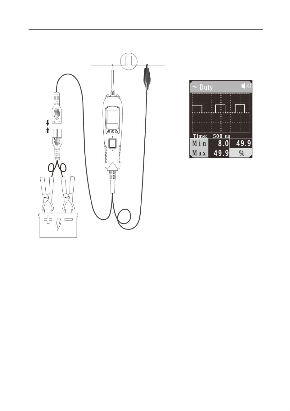
5.4 Duty Cycle
Figure 6
1) Clip the red alligator clip to the battery positive pole; Clip the black alligator clip to
the battery negative pole.
2) Once the device is powered on, it will enter DC voltage test mode as default.
Short press the mode button to enter the menu, short press the down button to
place the cursor in the Duty Cycle mode, and short press the mode button to
enter the Duty Cycle waveform display mode.
3) The auxiliary ground wire is connected to the common end of the circuit under test,
and the probe contacts the test circuit. The LCD display will show the minimum
duty cycle, maximum duty cycle and waveform duty cycle (Figure 6), and display
the signal waveform in real time. You can adjust the sampling frequency by
pressing the Up/Down Button. In Figure 6, “time: 500us” is the time interval
indicated by each large grid. This time reading will change with the sampling
frequency.
4) Long press and hold the mode button until the device switches to digital display
mode. The LCD display will display the current duty cycle, minimum duty cycle,
and maximum duty cycle.
Vehicle Circuit Probe
- 11 -
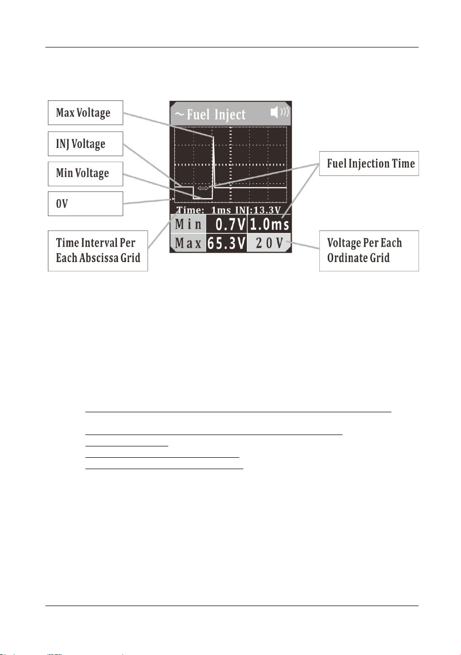
5.5 Fuel Inject
Figure 7
1) Clip the red alligator clip to the battery positive pole; Clip the black alligator clip to
the battery negative pole.
2) Once the device is powered on, it will enter DC voltage test mode as default.
Short press the mode button to enter the menu, short press the down button to
place the cursor in the Fuel Inject mode, and short press the mode button to enter
the Fuel Inject waveform display mode.
3) Let the auxiliary ground wire be grounded, have the probe tip contact the negative
electrode of the injector control circuit, and the LCD display will read:
a) Maximum Reverse Induced Voltage Value of Fuel Injector Control Coil,
shown as Max (If it exceeds 35V, the red LED light will flash);
b) Minimum Ground Voltage Value When Fuel Injection Is ON, shown as Min;
c) Fuel Injection Time;
d) Fuel Injector Power Supply Voltage (INJ voltage), as shown in (Figure 7);
e) Display Signal Real-Time Waveform.
You can adjust the voltage per each ordinate grid in the waveform by pressing the
up button, and press the down button to adjust the time interval per each abscissa
grid.
(Figure 7) “time: 1ms” is the time interval indicated by each grid in the waveform,
which will vary with the sampling frequency.
The voltage value shown on the lower right corner is the voltage value per each
ordinate grid.
The green triangle mark indicates the position of 0V in the ordinate, as shown in
(Figure 7).
4) Long press and hold the mode button until the device switches to digital display
mode. It reads:
Vehicle Circuit Probe
- 12 -
a) Fuel Injection Time, displayed in the main area;
b) Fuel Injector Power Supply Voltage (INJ Voltage), displayed at the top;
c) Maximum Reverse Induced Voltage Value of Fuel Injector Control Coil,
shown as Max (If it exceeds 35V, the red LED light will flash); and
d) Minimum Ground Voltage Value When Fuel Injection Is ON, shown as Min.
To reset the maximum and minimum values, press the mode button twice.
In this mode, if it fails to detect a valid injection pulse, a bar symbol will display
instead, as shown in (Figure 7).
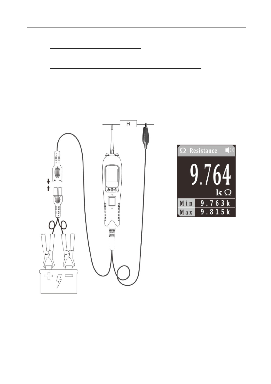
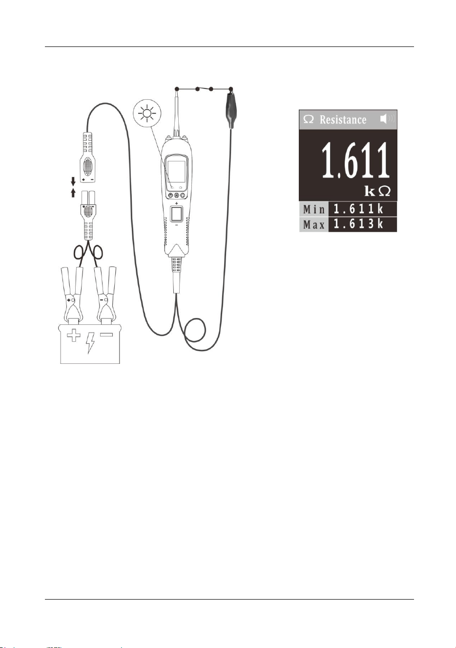
5.6 Resistance
Figure 8
1) Clip the red alligator clip to the battery positive pole; Clip the black alligator clip to
the battery negative pole.
2) Once the device is powered on, it will enter DC voltage test mode as default.
Short press the mode button to enter the menu, short press the down button to
Vehicle Circuit Probe
- 13 -
place the cursor in the Resistance mode, and short press the mode button to
enter the Resistance mode.
3) The probe contacts one end of the measured resistance, and the auxiliary ground
lead is connected to the other end of the measured resistance. The LCD display
will read the resistance between the tip and auxiliary ground lead. (Figure 8)
4) When resistance value is less than 30Ω, the instrument buzzer will alarm and the
green LED will light. This function can be used as continuity test.
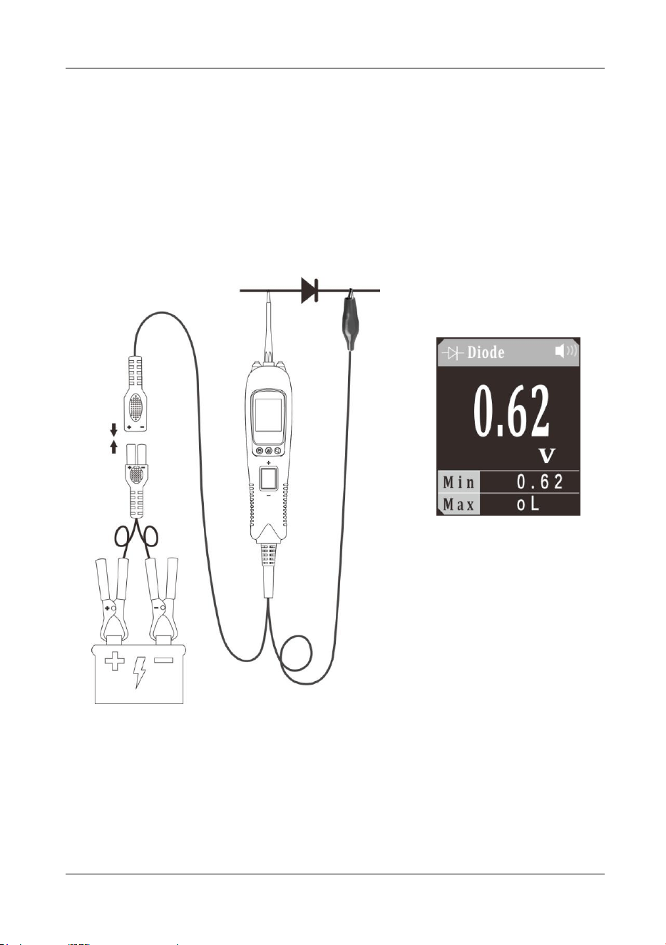
5.7 Diode
Figure 9
1) Clip the red alligator clip to the battery positive pole; Clip the black alligator clip to
the battery negative pole.
2) Once the device is powered on, it will enter DC voltage test mode as default.
Short press the mode button to enter the menu, short press the down button to
place the cursor in the Diode mode, and short press the mode button to enter the
Diode mode.
Vehicle Circuit Probe
- 14 -
3) Contact the probe tip to diode positive terminal, connect the auxiliary ground lead
to diode negative terminal, the screen will display the forward voltage drop, which
indicates forward bias. If swapping the probe tip with auxiliary ground lead, the
screen will not display voltage, which indicates reverse bias. It also displays the
maximum and minimum values during measurement, as shown in (Figure 9).
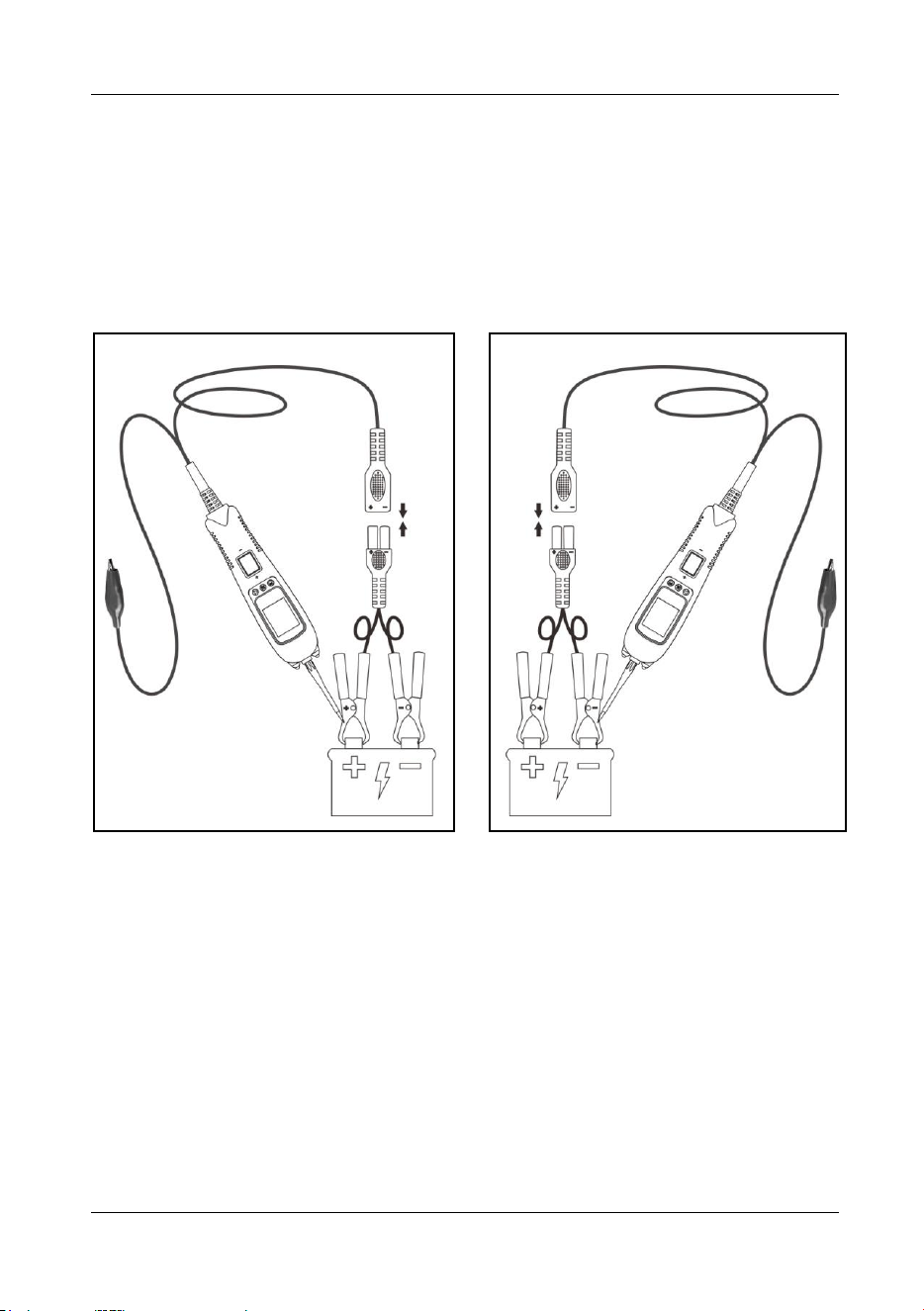
5.8 Voltage & Polarity Testing
Figure 10 Figure 11
1) Clip the red alligator clip to the battery positive pole; Clip the black alligator clip to
the battery negative pole.
2) Contact the probe tip to the circuit under test.
3) If contact the probe tip to a POSITIVE circuit (Figure 10), the red LED will light
and the LCD displays the voltage with a highest resolution of 0.01V. A beep tone
will sound. If contact the probe tip to a NEGATIVE circuit (Figure 11), the green
LED will light and the LCD displays the voltage with a highest resolution of 0.01V.
A beep tone will sound. If contact the probe tip to an OPEN circuit, neither of the
LED will light.
Vehicle Circuit Probe
- 15 -
5.9 Continuity Testing
Figure 12
1) Clip the red alligator clip to the battery positive pole; Clip the black alligator clip to
the battery negative pole.
2) Once the device is powered on, it will enter DC voltage test mode as default.
Short press the mode button to enter the menu, short press the down button to
place the cursor in the Resistance mode, and short press the mode button to
enter the Resistance mode.
3) Using the probe tip and the auxiliary ground lead, it can test continuity of wires
and components connected or disconnected with the vehicle’s electrical system.
When the probe tip is contacting a good ground, the LCD will show 0Ω and green
LED will be on. A beep tone will sound .
4) In other cases, the LCD shows the resistance of the component under test, along
with the maximum and minimum values during the measurement, as shown in
Figure 12.
5) If the resistance value is greater than 1000KΩ, the LCD will show “0L”.
6) Note: You can use the probe tip to pierce the plastic insulation on a wire. This
means that you can test the circuit without disconnecting anything.
Vehicle Circuit Probe
- 16 -
5.10 Signal Circuit Testing
Figure 13
Once you extract a DTC from the vehicle and realize that troubleshooting begins with
some kind of sensor circuit, there is a quick test you can perform to verify the code.
Testing your sensor is easy while using the tool.
For example, if you suspect there is a problem with your M.A.P. sensor circuit, then
you may follow the procedure involved to test this sensor:
1) Set the tool in AC Voltage mode, using the probe tip (with chassis ground) or the
auxiliary ground lead.
2) Connect vacuum pump to MAP sensor.
3) Contact the probe tip to the MAP sensor positive terminal and observe the LCD
readings which should be a sine wave in normal condition.
4) Apply vacuum.
5) Release vacuum and observe the LCD readings. (Figure 13)
6) If the LCD readings are abnormal, there is a problem with this sensor.
Vehicle Circuit Probe
- 17 -
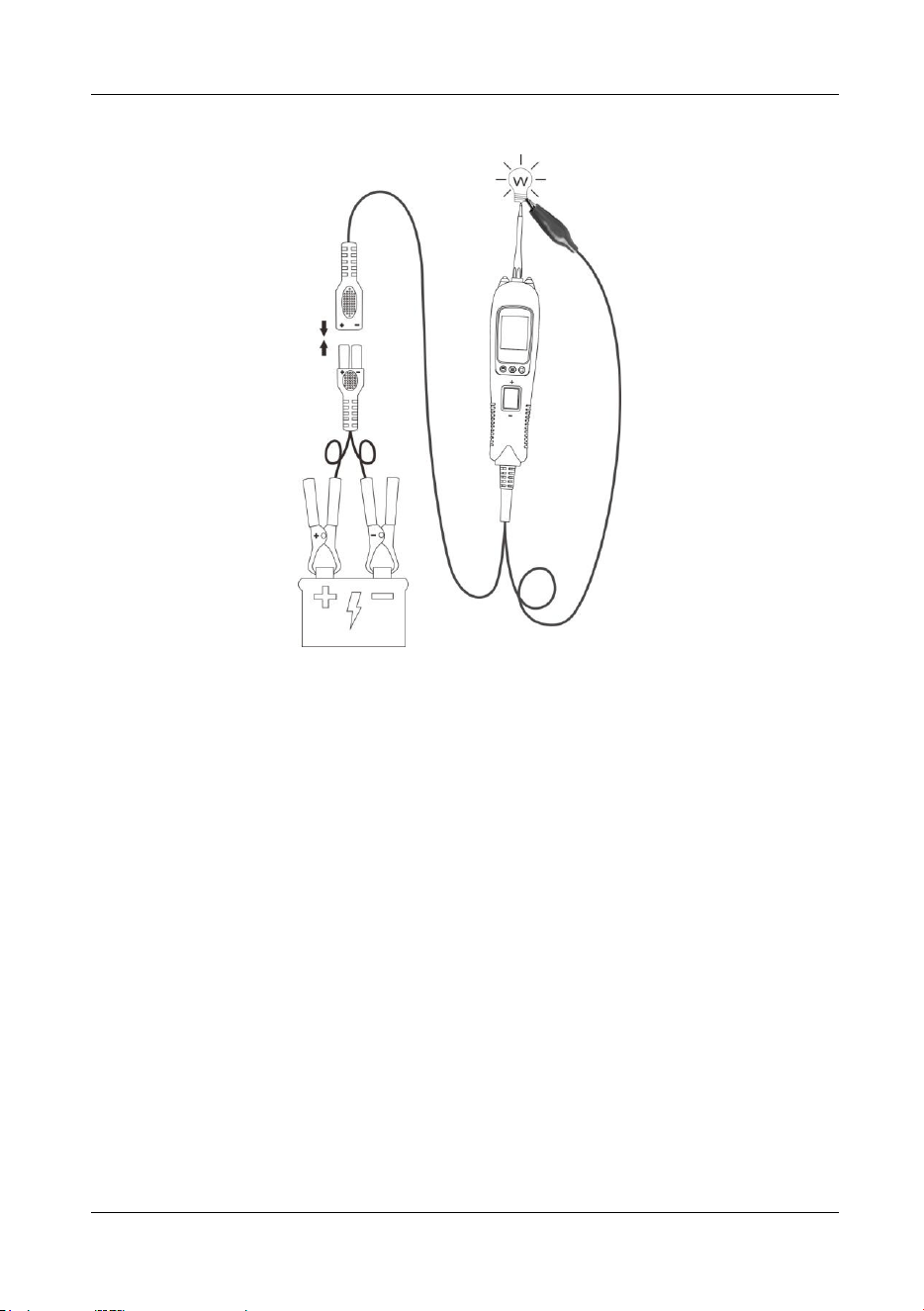
5.11 Activating Components in Your Hand
Figure 14
1) While the tool is in DC voltage mode, by using the probe tip in connection with the
auxiliary ground lead, components can be activated right in your hand, thereby
testing their functions.
2) Connect the auxiliary ground lead to the negative terminal or ground side of the
component being tested. Then contact the probe tip to the positive terminal of the
component, the green LED should light, indicating continuity through the
component. While keeping an eye on the green LED, quickly press and release
the rocker switch forward. If the green LED went out and the red LED came on,
you may proceed with further activation. Rock the rocker switch forward and hold
it down to provide power to your component. With the rocker switch rocked
forward, power will flow from the positive lead on the battery into the probe tip,
through the tip into the component’s positive terminal, into the component and out
of the component, through the auxiliary ground lead and back into the tool, and
back to the vehicle’s battery’s ground.
3) Press the rocker switch forward to activate the bulb.(Figure 14). Contact the tip to
the positive terminal of the bulb.Connect the negative auxiliary clip. If the green
LED went off at that instant or if the circuit breaker tripped, the tool has been
overloaded. This could happen for the following reasons:
The contact you are probing is direct ground or negative voltage.
The component you are testing is short-circuit.
The component is a very high current component (i.e., starter motor).
If the circuit breaker is tripped, reset it by waiting for it to cool down (about 1 minute).
Vehicle Circuit Probe
- 18 -
5.12 Activating Components in the Vehicle
Figure 15
1) While the tool in DC Voltage mode, contact the probe tip to the positive terminal of
the component, the green LED should light, indicating continuity to ground.
2) Observe the green LED, quickly depress and release the rocker switch forward. If
the green LED went out and the red LED came on, you may proceed with further
activation. (Figure 15) If the green LED went off at that instant or if the circuit
breaker tripped, the tool has been overloaded. This could happen for the following
reasons:
The contact you are probing is a direct ground.
The component you are testing is short-circuited.
The component is a very high current component (i.e., starter motor).
If the circuit breaker is tripped, reset it by waiting for it to cool down (about 1 minute.)
WARNING: Haphazardly applying voltage to certain circuits can cause damage to a
vehicle’s electronic components. Therefore, it is strongly advised to use the vehicle
manufacturer’s schematic and diagnosing procedure while testing.
NOTE: When powering up components, you can increase the life of rocker switch if
you first press the switch, then contact the tip to the component. The arcing will take
place at the tip instead of the contacts of the switch.
Vehicle Circuit Probe
- 19 -
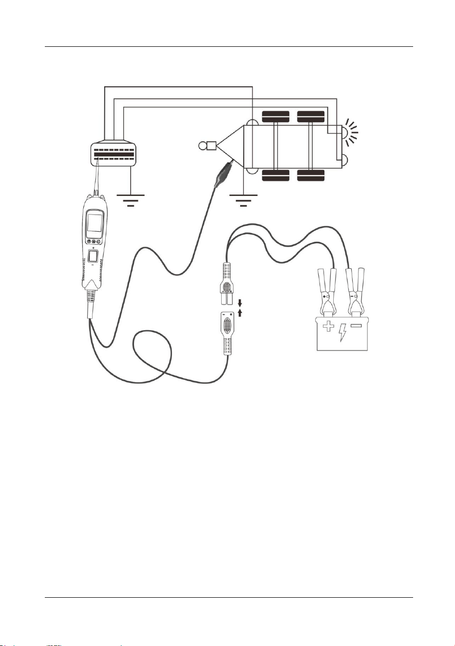
5.13 Testing Trailer Lights and Connections
Figure 16
1) While the tool in DC Voltage mode, clip the auxiliary ground lead to the trailer
ground, probe the contacts at the jack and then apply voltage to the probe tip.
This may check the function and orientation of the connector and trailer lights.
(Figure 16)
2) If the circuit breaker tripped, that contact is likely a ground. Reset the circuit
breaker by letting it cool down for 1 minute.
Vehicle Circuit Probe
- 20 -
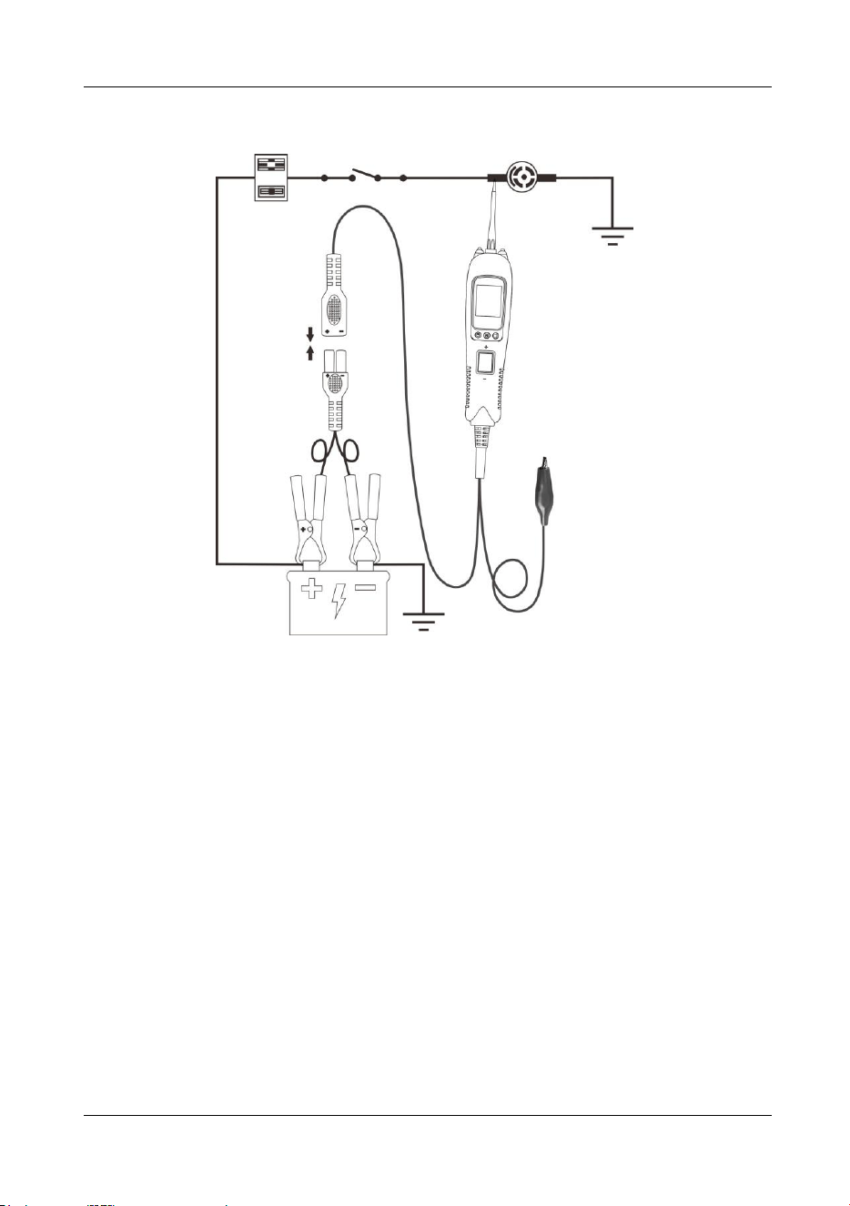
5.14 Activating Components W/Ground
Figure 17
1) While the tool in DC Voltage mode, contact the probe tip to the negative terminal
of the component, the red LED should light. While observing the red LED, quickly
depress and release the rocker switch rearward. If the red LED went out and the
green LED came on, you may proceed with further activation. (Figure 17)
2) If the green LED went off at that instant or if the circuit breaker tripped, the tool
has been overloaded. This could happen for the following reasons:
The contact you are probing is a direct positive voltage.
The component you are testing is short-circuited.
The component is a very high current component (i.e., starter motor).
If the circuit breaker is tripped, reset it by waiting for it to cool down (about 1 minute.).
WARNING: With this function, if you are contacting a protected circuit, a vehicle’s
fuse can be blown or tripped if you apply ground to it.

Vehicle Circuit Probe
- 21 -
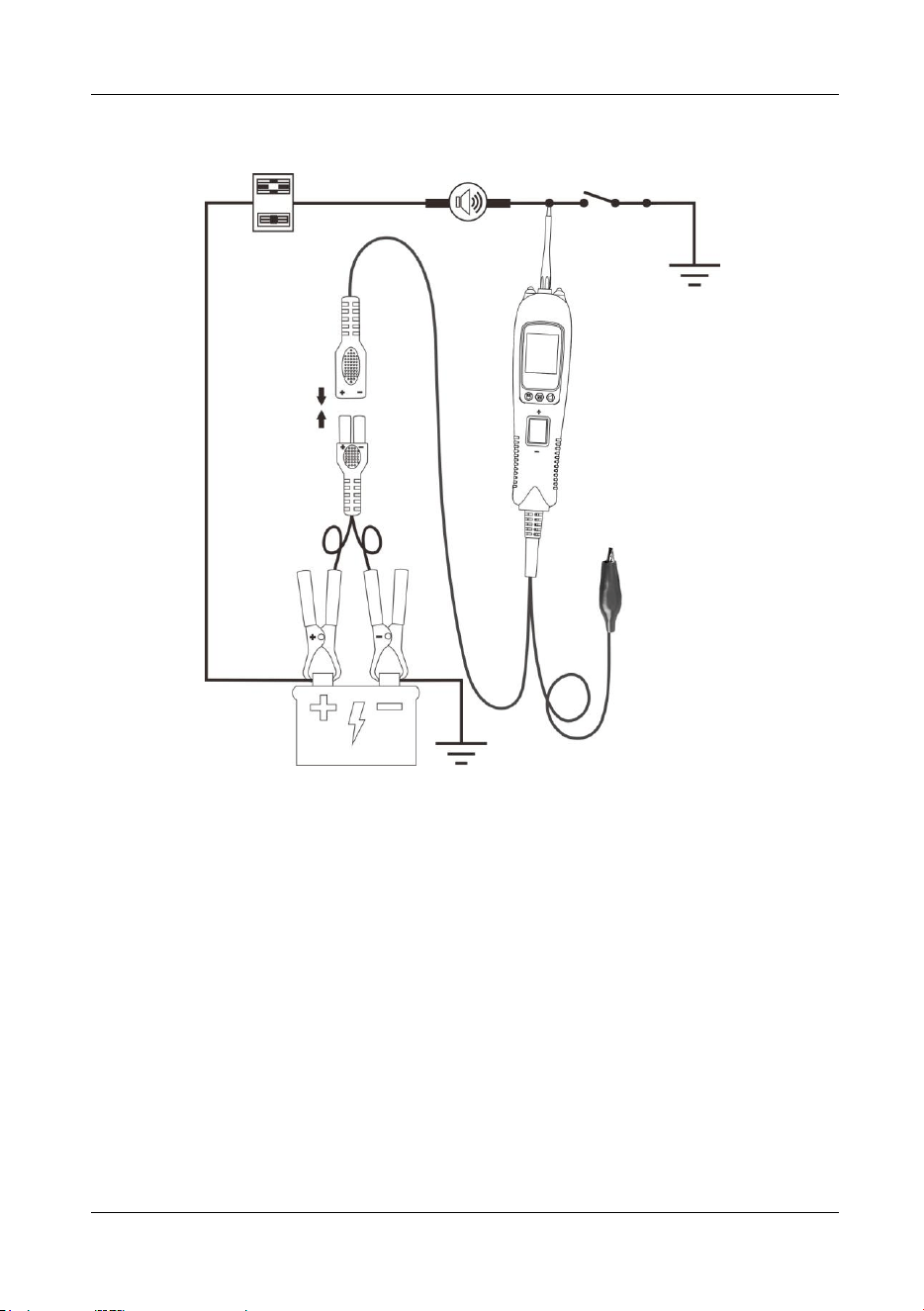
5.15 Following & Locating Short Circuits
In most cases a short circuit will appear by a fuse or a fusible link blowing or an
electrical protection device tripping (i.e., a circuit breaker). This is the best place to
begin the search.
Remove the blow fuse from the fuse box.
Use the probe tip to activate and energize each of the fuse contacts. The contact
which trips the circuit breaker is the shorted circuit. Take note of this wire’s
identification code or color.
Follow the wire as far as you can along the wiring harness.
Here is an example for this application.
If you are following a short in the brake light circuit, you may know that the wire must
pass through the wiring harness at the door sill. Locate the color-coded wire in the
harness and expose it.
Probe through the insulation with the probe tip, and depress the rocker switch forward
to activate and energize the wire.
If the circuit breaker tripped, you have verified the shorted wire. Cut the wire and
energize each end with the probe tip. The wire end which trips the circuit breaker
again is the shorted circuit and it will lead you to the shorted area.
Follow the wire in the shorted direction and repeat this process until the short is
located.
5.16 Checking for Bad Ground Contacts
Probe the suspected ground wire or contact with the probe tip.
Observe the green LED. Depress the rocker switch forward then release. If the green
LED went out and the red LED came on, a beep will sound, this is not a true ground.
If the circuit breaker tripped, this circuit is more than likely a good ground. Keep in
mind that high current components such as starter motors will also trip the circuit
breaker.
6. Parts List
Part
Description
Qty
1
Vehicle Super Probe
1
2
Probe Tip
1
3
Crochet Hook
1
4
Crochet Hook Extension Cable
1
5
Battery Clamp Cable
1
6
User’s Manual
1
7
Rugged Blow Molded Case
1

Limited 90 Day Warranty
ANCEL makes every effort to assure that its products meet high quality and durability
standards, and warrants to the original purchaser that this product is free from
defects in materials and workmanship for the period of 90 days from the date of
purchase. This warranty does not apply to damage due directly or indirectly, to
misuse, abuse, negligence or accidents, repairs or alterations outside our facilities,
criminal activity, improper installation, normal wear and tear, or to lack of
maintenance. We shall in no event be liable for death, injuries to persons or property,
or for incidental, contingent, special or consequential damages arising from the use
of our product. Some states do not allow the exclusion or limitation of incidental or
consequential damages, so the above limitation of exclusion may not apply to you.
THIS WARRANTY IS EXPRESSLY IN LIEU OF ALL OTHER WARRANTIES,
EXPRESS OR IMPLIED, INCLUDING THE WARRANTIES OF MERCHANTABILITY
AND FITNESS.
To take advantage of this warranty, the product or part must be returned to us with
transportation charges prepaid. Proof of purchase date and an explanation of the
complaint must accompany the merchandise. If our inspection verifies the defect, we
will either repair or replace the product at our election or we may elect to refund the
purchase price if we cannot readily and quickly provide you with a replacement. We
will return repaired products at our expense, but if we determine there is no defect, or
that the defect resulted from causes not within the scope of our warranty, then you
must bear the cost of returning the product.
This warranty gives you specific legal rights and you may also have other rights
which vary from state to state.
OBDSPACE TECHNOLOGY CO., LTD
Address: D03, Block A, No.973 Minzhi Ave, Longhua District, Shenzhen, Guangdong, China