31-5000950 Rev. 0 09-25
NS19H
VARIABLE SPEED HIGH
EFFICIENCY SPLIT HEAT PUMP
Service
Manual
READ CAREFULLY.
KEEP THESE INSTRUCTIONS
.
GE is a trademark of the General Electric Company. Manufactured under trademark license.
Contact GE Appliances at:
Homeowner: GEAppliances.com
HVAC Pro: GEAppliancesAirandWater.com
or
866.814.3633
Split System USAC and USHP matches:
AHRIDirectory.org
2
31-5000950 Rev. 0
These instructions are intended as a general guide and do not supersede national or local codes in any way. Consult
authorities having jurisdiction before installation.
The NS19HLVDKLJKHႈFLHQF\VSOLWV\VWHPDLUFRQGLWLRQHUZLWKDOODOXPLQXPFRLOGHVLJQHGIRUXVHZLWK5%
refrigerant only.
The NS19H units feature a variable capacity rotary compressor.
This unit must be installed with an approved indoor air handler or coil. See AHRIDirectory.org for approved indoor
component match ups.
These instructions are intended as a general guide and do not supersede local codes in any way. Consult authorities
having jurisdiction before installation.
This outdoor unit is designed for use in systems that use the following refrigerant metering device:
• Check thermal expansion valve (CTXV)
IMPORTANT
Special procedures are required for cleaning the all-aluminum coil in this unit.
WARNING
• Electric Shock Hazard. High Voltage. Wait 7 minutes after power is removed before servicing to allow stored
energy to dissipate.
• Electrical components may hold charge.
General Information

3
31-5000950 Rev. 0
Safety Information
WARNING
,PSURSHULQVWDOODWLRQDGMXVWPHQWDOWHUDWLRQVHUYLFHRU
PDLQWHQDQFHFDQFDXVHSURSHUW\GDPDJHSHUVRQDOLQMXU\
or loss of life. Installation and service must be performed
E\DOLFHQVHGSURIHVVLRQDO+9$&LQVWDOOHURUHTXLYDOHQW
VHUYLFHDJHQF\RUWKHJDVVXSSOLHU
• To prevent serious injury or death:
1. Lock-out/tag-out before performing maintenance.
,IV\VWHPSRZHULVUHTXLUHGHJVPRNHGHWHFWRU
PDLQWHQDQFHGLVDEOHSRZHUWREORZHUUHPRYHIDQ
EHOWZKHUHDSSOLFDEOHDQGHQVXUHDOOFRQWUROOHUV
and thermostats are set to the “OFF” position before
performing maintenance.
$OZD\VNHHSKDQGVKDLUFORWKLQJMHZHOU\WRROVHWF
away from moving parts.
• Do not use means to accelerate the defrosting process
RUWRFOHDQRWKHUWKDQWKRVHUHFRPPHQGHGE\WKH
manufacturer.
• The appliance shall be stored in a room without
continuously operating ignition sources (for example:
RSHQÀDPHVDQRSHUDWLQJJDVDSSOLDQFHRUDQRSHUDWLQJ
electric heater).
• Do not pierce or burn.
• Be aware that refrigerants may not contain an odor.
• Ducts connected to an appliance shall not contain a
potential ignition source
(YHU\ZRUNLQJSURFHGXUHWKDWDႇHFWVVDIHW\PHDQVVKDOO
only be carried out by competent persons. This appliance
is not to be used by persons (including children) with
UHGXFHGSK\VLFDOVHQVRU\RUPHQWDOFDSDELOLWLHVRUODFN
RIH[SHULHQFHDQGNQRZOHGJHXQOHVVWKH\KDYHEHHQ
given supervision or instruction concerning use of the
appliance by a person responsible for their safety.
• Children should be supervised to ensure they do not play
with the appliance.
• PARTIAL UNITS shall only be connected to an appliance
suitable for the same refrigerant.
CAUTION
$VZLWKDQ\PHFKDQLFDOHTXLSPHQWFRQWDFWZLWKVKDUS
sheet metal edges can result in personal injury. Take
care while handling this equipment and wear gloves and
protective clothing.
• Servicing shall be performed only as recommended by
the manufacturer.
• Under no circumstances shall potential sources of ignition
be used in the searching for or detection of refrigerant
leaks. A halide torch (or any other detector using a naked
ÀDPHVKDOOQRWEHXVHG
• The following leak detection methods are deemed
acceptable for all refrigerant systems.
• Electronic leak detectors may be used to detect
UHIULJHUDQWOHDNVEXWLQWKHFDVHRIÀDPPDEOH
UHIULJHUDQWVWKHVHQVLWLYLW\PD\QRWEHDGHTXDWHRU
may need recalibrating. (Detection equipment shall be
calibrated in a refrigerant-free area.) Ensure that the
detector is not a potential source of ignition and is suitable
for the refrigerant used. Leak detection equipment shall
be set at a percentage of the LFL of the refrigerant and
VKDOOEHFDOLEUDWHGWRWKHUHIULJHUDQWHPSOR\HGDQG
the appropriate percentage of gas (25 % maximum) is
FRQ¿UPHG/HDNGHWHFWLRQÀXLGVDUHDOVRVXLWDEOHIRUXVH
with most refrigerants but the use of detergents containing
chlorine shall be avoided as the chlorine may react with
the refrigerant and corrode the copper pipe-work. If a
OHDNLVVXVSHFWHGDOOQDNHGÀDPHVVKDOOEHUHPRYHG
extinguished. If a leakage of refrigerant is found which
UHTXLUHVEUD]LQJDOORIWKHUHIULJHUDQWVKDOOEHUHFRYHUHG
IURPWKHV\VWHPRULVRODWHGE\PHDQVRIVKXWRႇYDOYHV
in a part of the system remote from the leak.
• Some soaps used for leak detection are corrosive to
certain metals. Carefully rinse piping thoroughly after leak
WHVWKDVEHHQFRPSOHWHG'RQRWXVHPDWFKHVFDQGOHV
ÀDPHRURWKHUVRXUFHVRILJQLWLRQWRFKHFNIRUJDVOHDNV

4
31-5000950 Rev. 0
Safety Information
IMPORTANT
• The Clean Air Act of 1990 bans the intentional venting of
UHIULJHUDQW&)&V+&)&VDQG+)&VDVRI-XO\
$SSURYHGPHWKRGVRIUHFRYHU\UHF\FOLQJRUUHFODLPLQJ
must be followed. Fines and/or incarceration may be
levied for noncompliance.
7KLVXQLWPXVWEHPDWFKHGZLWKDQLQGRRUFRLODVVSHFL¿HG
LQ/HQQR[3URGXFW6SHFL¿FDWLRQEXOOHWLQ&RLOVSUHYLRXVO\
FKDUJHGZLWK+&)&PXVWEHÀXVKHG
7KLVXQLWPXVWEHPDWFKHGZLWKDQLQGRRUFRLODVVSHFL¿HG
ZLWK$+5,)RU$+5,&HUWL¿HGV\VWHPPDWFKXSVDQG
H[SDQGHGUDWLQJVYLVLWGEAppliances.com.
• Ensure that the area is in the open or that it is adequately
ventilated before breaking into the system or conducting
any hot work. A degree of ventilation shall continue during
the period that the work is carried out.
9HULI\FDEOLQJZLOOQRWEHVXEMHFWWRZHDUFRUURVLRQ
H[FHVVLYHSUHVVXUHYLEUDWLRQVKDUSHGJHVRUDQ\RWKHU
DGYHUVHHQYLURQPHQWDOHႇHFWV
3LSHZRUNLQFOXGLQJSLSLQJPDWHULDOSLSHURXWLQJDQG
installation shall include protection from physical damage
LQRSHUDWLRQDQGVHUYLFHDQGEHLQFRPSOLDQFHZLWK
QDWLRQDODQGORFDOFRGHVDQGVWDQGDUGVVXFKDV$6+5$(
$6+5$(,$3028QLIRUP0HFKDQLFDO&RGH,&&
,QWHUQDWLRQDO0HFKDQLFDO&RGHRU&6$%$OO¿HOGMRLQWV
shall be accessible for inspection prior to being covered or
enclosed.
• When breaking into the refrigerant circuit to make repairs
– or for any other purpose – conventional procedures
VKDOOEHXVHG+RZHYHUIRUÀDPPDEOHUHIULJHUDQWVLW
LVLPSRUWDQWWKDWEHVWSUDFWLFHEHIROORZHGDQGVLQFH
ÀDPPDELOLW\LVDFRQVLGHUDWLRQSURFHGXUHV such as
safely remove refrigerant following local and national
UHJXODWLRQVSXUJLQJWKHFLUFXLWZLWKLQHUWJDV evacuating
RSWLRQDOIRU$/SXUJLQJZLWKLQHUWJDV (optional for
$/RURSHQLQJWKHFLUFXLWE\FXWWLQJRU brazing be
adhered to. The refrigerant charge shall be recovered into
the correct recovery cylinders if venting is not allowed
by local and national codes. For appliances containing
ÀDPPDEOHUHIULJHUDQWVWKHV\VWHPVKDOOEH purged with
oxygen-free nitrogen to render the appliance safe for
ÀDPPDEOHUHIULJHUDQWV
• This process might need to be repeated several times.
Compressed air or oxygen shall not be used for purging
UHIULJHUDQWV\VWHPV)RUDSSOLDQFHVFRQWDLQLQJÀDPPDEOH
UHIULJHUDQWVUHIULJHUDQWSXUJLQJVKDOOEHDFKLHYHG by
breaking the vacuum in the system with oxygen-free
QLWURJHQDQGFRQWLQXLQJWR¿OOXQWLOWKHZRUNLQJ pressure
LVDFKLHYHGWKHQYHQWLQJWRDWPRVSKHUHDQG ¿QDOO\
pulling down to a vacuum (optional for A2L). This process
shall be repeated until no refrigerant is within the system
RSWLRQDOIRU$/:KHQWKH¿QDOR[\JHQIUHH nitrogen
FKDUJHLVXVHGWKHV\VWHPVKDOOEHYHQWHG down to
atmospheric pressure to enable work to take place.
Ensure that the outlet for the vacuum pump is not close
to any potential ignition sources and that ventilation is
available.
,QDGGLWLRQWRFRQYHQWLRQDOFKDUJLQJSURFHGXUHVWKH
following requirements shall be followed.
±(QVXUHWKDWFRQWDPLQDWLRQRIGLႇHUHQWUHIULJHUDQWV
does not occur when using charging equipment. Hoses
or lines shall be as short as possible to minimize the
amount of refrigerant contained in them.
– Cylinders shall be kept in an appropriate position
according to the instructions.
– Ensure that the REFRIGERATING SYSTEM is earthed
prior to charging the system with refrigerant.
– Label the system when charging is complete (if not
already).
±([WUHPHFDUHVKDOOEHWDNHQQRWWRRYHU¿OOWKH
REFRIGERATING SYSTEM.
3ULRUWRUHFKDUJLQJWKHV\VWHPLWVKDOOEHSUHVVXUH
tested with the appropriate purging gas. The system shall
EHOHDNWHVWHGRQFRPSOHWLRQRIFKDUJLQJEXWSULRU to
commissioning. A follow up leak test shall be carried out
prior to leaving the site.
:KHQUHPRYLQJUHIULJHUDQWIURPDV\VWHPHLWKHUIRU
VHUYLFLQJRUGHFRPPLVVLRQLQJLWLVUHFRPPHQGHGJRRG
practice that all refrigerants are removed safely. When
WUDQVIHUULQJUHIULJHUDQWLQWRF\OLQGHUVHQVXUH that only
appropriate refrigerant recovery cylinders are employed.
Ensure that the correct number of cylinders for holding the
total system charge is available. All cylinders to be used
are designated for the recovered refrigerant and labelled
for that refrigerant (i. e. special cylinders for the recovery
of refrigerant). Cylinders shall be complete with pressure-
relief valve and associated VKXWRႇYDOYHVLQJRRGZRUNLQJ
order. Empty recovery F\OLQGHUVDUHHYDFXDWHGDQGLI
SRVVLEOHFRROHGEHIRUH recovery occurs.
• The recovery equipment shall be in good working order
with a set of instructions concerning the equipment
that is at hand and shall be suitable for the recovery of
all DSSURSULDWHUHIULJHUDQWVLQFOXGLQJZKHQDSSOLFDEOH
ÀDPPDEOHUHIULJHUDQWV,QDGGLWLRQDVHWRIFDOLEUDWHG
weighing scales shall be available and in good working
order. Hoses shall be complete with leak-free disconnect
couplings and in good condition. Before using the
UHFRYHU\PDFKLQHFKHFNWKDWLWLVLQVDWLVIDFWRU\ZRUNLQJ
RUGHUKDVEHHQSURSHUO\PDLQWDLQHGDQGWKDWDQ\
associated electrical components are sealed to prevent
ignition in the event of a refrigerant release. Consult
manufacturer if in doubt.
• The recovered refrigerant shall be returned to the
UHIULJHUDQWVXSSOLHULQWKHFRUUHFWUHFRYHU\F\OLQGHU
and the relevant waste transfer note arranged. Do not
mix refrigerants in recovery units and especially not in
cylinders.

5
31-5000950 Rev. 0
Safety Information
IMPORTANT
,IFRPSUHVVRUVRUFRPSUHVVRURLOVDUHWREHUHPRYHG
ensure that they have been evacuated to an acceptable
OHYHOWRPDNHFHUWDLQWKDWÀDPPDEOHUHIULJHUDQWGRHVQRW
remain within the lubricant. The evacuation process shall
be carried out prior to returning the compressor to the
suppliers. Only electric heating to the compressor body
shall be employed to accelerate this process. When oil is
GUDLQHGIURPDV\VWHPLWVKDOOEHFDUULHGRXWVDIHO\
$IWHUFRPSOHWLRQRI¿HOGSLSLQJIRUVSOLWV\VWHPVWKH
¿HOGSLSHZRUNVKDOOEHSUHVVXUHWHVWHGZLWKDQLQHUWJDV
DQGWKHQYDFXXPWHVWHGSULRUWRUHIULJHUDQWFKDUJLQJ
according to the following requirements;
– Field-made refrigerant joints indoors shall be tightness
tested. The test method shall have a sensitivity of .2 oz.
SHU\HDURIUHIULJHUDQWRUEHWWHUXQGHUSUHVVXUH
– No leak shall be detected.
• Prior to beginning work on systems containing
FLAMMABLE REFRIGERANTSVDIHW\FKHFNVDUH
necessary to ensure that the risk of ignition is minimized.
• Work shall be undertaken under a controlled procedure so
DVWRPLQLPL]HWKHULVNRIDÀDPPDEOHJDVRUYDSRU being
present while the work is being performed.
$OOPDLQWHQDQFHVWDႇDQGRWKHUVZRUNLQJLQWKHORFDO area
shall be instructed on the nature of work being carried out.
:RUNLQFRQ¿QHGVSDFHVVKDOOEHDYRLGHG
• The area shall be checked with an appropriate refrigerant
GHWHFWRUSULRUWRDQGGXULQJZRUNWRHQVXUHWKHWHFKQLFLDQ
LVDZDUHRISRWHQWLDOO\WR[LFRUÀDPPDEOHDWPRVSKHUHV
Ensure that the leak detection equipment being used
is VXLWDEOHIRUXVHZLWKDOODSSOLFDEOHUHIULJHUDQWVLH
QRQVSDUNLQJ adequately sealed or intrinsically safe.
• If any hot work is to be conducted on the refrigerating
HTXLSPHQWRUDQ\DVVRFLDWHGSDUWVDSSURSULDWH¿UH
extinguishing equipment shall be available to hand. Have
DGU\SRZGHURU&2ð¿UHH[WLQJXLVKHUDGMDFHQWWR the
charging area.
• No person carrying out work in relation to a
REFRIGERATING SYSTEM which involves exposing
any pipe work shall use any sources of ignition in such
DPDQQHUWKDWLWPD\OHDGWRWKHULVNRI¿UHRUH[SORVLRQ
$OOSRVVLEOHLJQLWLRQVRXUFHVLQFOXGLQJFLJDUHWWH
VPRNLQJVKRXOGEHNHSWVXႈFLHQWO\IDUDZD\IURPWKH
VLWHRILQVWDOODWLRQUHSDLULQJUHPRYLQJDQGGLVSRVDO
during which refrigerant can possibly be released to the
VXUURXQGLQJVSDFH3ULRUWRZRUNWDNLQJSODFHWKHDUHD
around the equipment is to be surveyed to make sure
WKDWWKHUHDUHQRÀDPPDEOHKD]DUGVRULJQLWLRQULVNV “No
Smoking” signs shall be displayed.
:KHUHHOHFWULFDOFRPSRQHQWVDUHEHLQJFKDQJHGWKH\
VKDOOEH¿WIRUWKHSXUSRVHDQGWRWKHFRUUHFWVSHFL¿FDWLRQ
At all times the manufacturer’s maintenance and service
JXLGHOLQHVVKDOOEHIROORZHG,ILQGRXEWFRQVXOWWKH
manufacturer’s technical department for assistance.
• The following checks shall be applied to installations using
FLAMMABLE REFRIGERANTS:
– the actual REFRIGERANT CHARGE is in accordance
with the room size within which the refrigerant
containing parts are installed;
– the ventilation machinery and outlets are operating
adequately and are not obstructed;
±LIDQLQGLUHFWUHIULJHUDWLQJFLUFXLWLVEHLQJXVHGWKH
secondary circuit shall be checked for the presence of
refrigerant;
– marking to the equipment continues to be visible and
legible. Markings and signs that are illegible shall be
corrected;
– refrigerating pipe or components are installed in a
position where they are unlikely to be exposed to any
substance which may corrode refrigerant containing
FRPSRQHQWVXQOHVVWKHFRPSRQHQWVDUHFRQVWUXFWHG
of materials which are inherently resistant to being
corroded or are suitably protected against being so
corroded. • Sealed electrical components shall be
replaced.
• Intrinsically safe components must be replaced.
6
31-5000950 Rev. 0
7HFKQLFDO6SHFL¿FDWLRQV
NOTE – R-454-B is an A2L refrigerant. The system installation must meet the following parameters based upon total
refrigerant charge (line set included). TAmin (Total minimum conditioned area) is the minimum allowable conditioned area
based upon the total system charge at sea level. Values must be multiplied by altitude adjustment factor at installed altitude.
4PLQWDEOHUHIHUVWRPLQLPXPDLUÀRZUHTXLUHPHQWVGXULQJUHIULJHUDQWOHDNPLWLJDWLRQE\WKHUHIULJHUDQWGHWHFWLRQV\VWHP
based upon total system charge. See tables below.
TAmin Table
Charge (lb) 10 15 20 25 30
Charge (kg) 4.5 6.8 9.1 11.3 13.6
Minimum Conditioned Area (ft2) 149.9 224.9 299.9 374.8 449.8
Minimum Conditioned Area (m2) 13.9 20.9 27.9 34.8 41.8
NOTE – Multiply values in TAmin table by the Altitude Adjustment Factors to correct TAmin based on installed altitude.
Altitude Adjustment Factor
Altitude (m) 0 200 400 600 800 1000 1200 1400 1600
Altitude (ft) 0 660 1310 1970 2620 3280 3940 4590 5250
Adj. Factor11111.021.051.041.11.12
Altitude (m) 1600 1800 2000 2200 2400 2600 2800 3000 3200
Altitude (ft) 5250 5910 6560 7220 7870 8530 9190 9840 10500
Adj. Factor 1.12 1.15 1.18 1.21 1.25 1.28 1.32 1.36 1.4
Qmin Table
Refrigerant Charge lb (kg) CFM Required Refrigerant Charge lb (kg) CFM Required
5 (2.3) 135 18 (8.1) 487
6 (2.7) 162 19 (8.6) 514
7 (3.2) 189 20 (9.1) 541
8 (3.6) 216 21 (9.5) 568
9 (4.1) 244 22 (10) 595
10 (4.5) 271 23 (10.4) 622
11 (5) 298 24 (10.9) 649
12 (5.4) 325 25 (11.3) 676
13 (5.9) 352 26 (11.7) 704
14 (6.4) 379 27 (12.2) 731
15 (6.8) 406 28 (12.7) 758
16 (7.3) 433 29 (13.2) 785
17 (7.7) 460 30 (13.6) 812
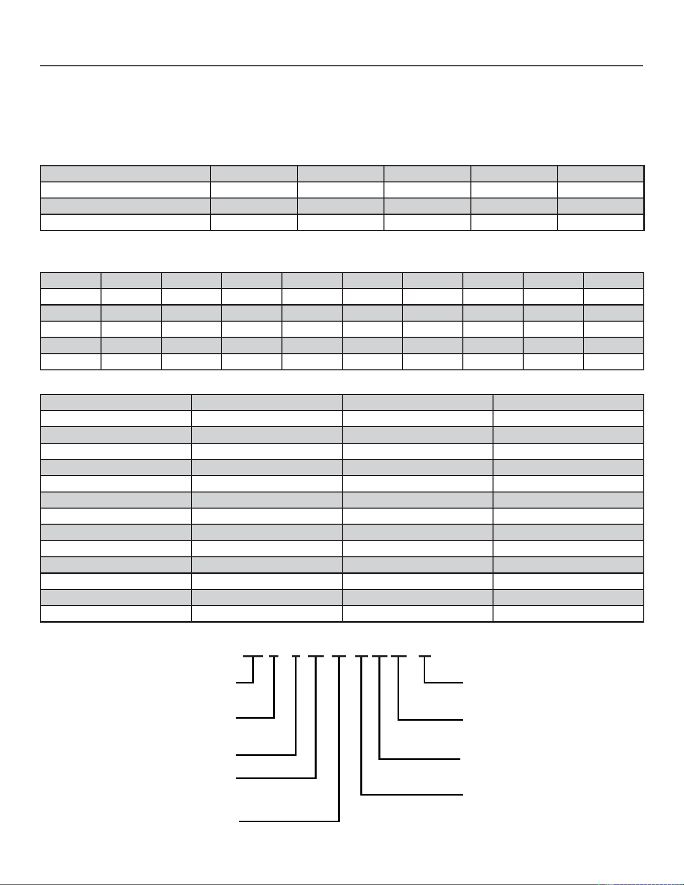
MODEL NUMBER GUIDE
MAJOR / MINOR
REVISION
REFRIGERANT
5-R-454B
VOLTAGE
A-208/230 1PH 60HZ
DESIGN VARIANT
M-MODULATING
BRAND
N-GE
PRODUCT
S-SPLIT
SEER
APPLICATION
H-HEAT PUMP
COOLING CAPACITY
(1000BTU/HR)
N S A – XX
XX
19
19
H 36
36
M 5
7
31-5000950 Rev. 0
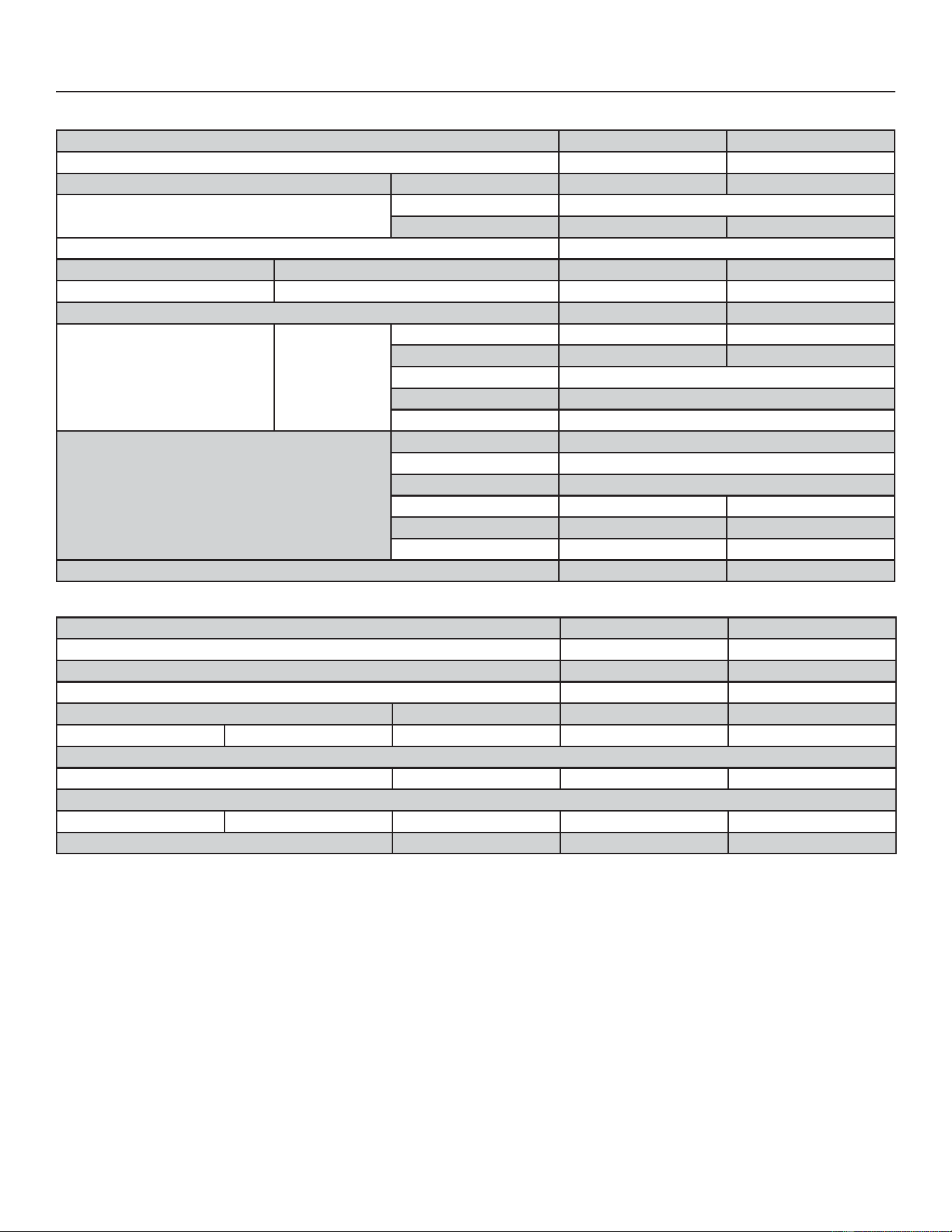
7HFKQLFDO6SHFL¿FDWLRQV
6SHFL¿FDWLRQV
Size 036 060
Nominal Tonnage 35
Sound Rating Number Range dBA 61-73 64-77
Connections
(Sweat)
Liquid line (OD) - in. 3/8
Vapor line (OD) - in. 7/8 1-1/8
Compressor Type Variable Rotary
Refrigerant (15 ft. Line Set) ¹ R-454B charge furnished
Refrigerant (30 ft. Line Set) ¹ R-454B charge furnished
Indoor Unit Expansion Valve (TXV) 26Z70 26Z72
Outdoor Coil
Net face area - ft.² Outer Coil 17.00 23.63
Inner Coil 16.25 22.79
Tube diameter - in. 5/16
Rows 2
Fins - in. 22
Outdoor Fan
HP 1/3
Diameter - in. 22
Blades 4
Cfm 2642 3907
Rpm 681 941
Watts 284 295
Shipping Data - lbs. 224 269
Electrical Data
Size 036 060
LIne voltage data (Volts-Phase-Hz) 208/230-1-60 208/230-1-60
² Maximum overcurrent protection (MOCP) amps 35 60
³ Minimum circuit ampacity (MCA) 23 39.2
Compressor Input amps 16.3 28.5
Fan Motor Full load amps 2.6 3.6
OPTIONAL CONTROLS - ORDER SEPARATELY
'LVFKDUJH$LU7HPSHUDWXUH6HQVRU 88K38
ŏŏ
OPTIONAL ACCESSORIES - ORDER SEPARATELY
Freezestat 3/8 in. 93G35
ŏŏ
,QGRRU%ORZHU2ႇ'HOD\5HOD\ 58M81
ŏŏ
NOTE - Extremes of operating range are plus 10% and minus 5% of line voltage.
ï5HIULJHUDQWFKDUJHVXႈFLHQWIRUIWOHQJWKRIUHIULJHUDQWOLQHV)RUORQJHUOLQHVHWUHTXLUHPHQWVVHHWKH,QVWDOODWLRQ,QVWUXFWLRQVIRULQIRUPDWLRQDERXWOLQHVHWOHQJWKDQG DGGLWLRQDOUHIULJHUDQWFKDUJH
required.
² HACR type breaker or fuse.
ñ5HIHUWR1DWLRQDORU&DQDGLDQ(OHFWULFDO&RGHPDQXDOWRGHWHUPLQHZLUHIXVHDQGGLVFRQQHFWVL]HUHTXLUHPHQWV
$GGVLQPPWRXQLWKHLJKW
8
31-5000950 Rev. 0
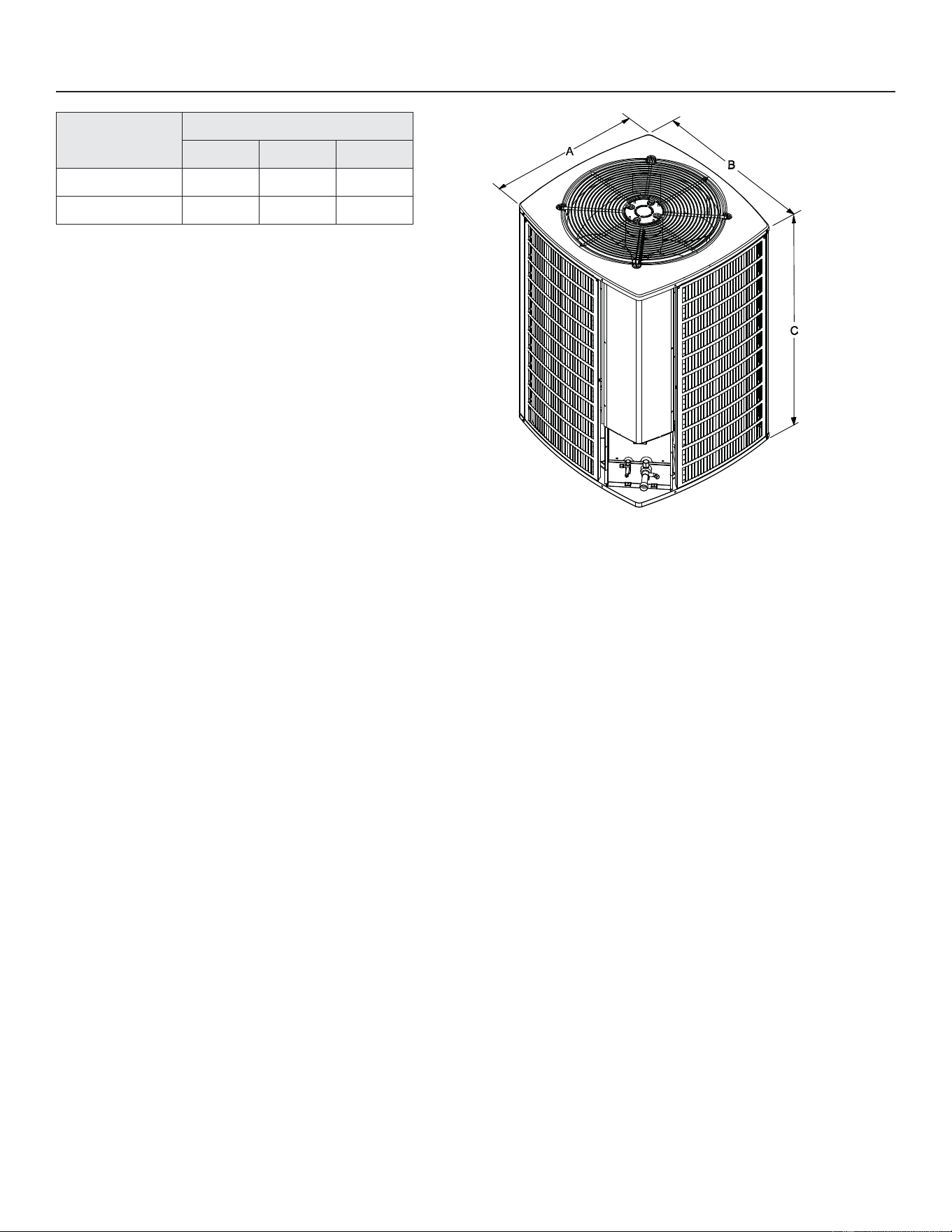
Unit Dimensions – inches (mm)
Model No.
Dimensions (inch)
A - Width B - Depth C - Height
NS19H36MA5 29.38 31.25 33.75
NS19H60MA5 29.38 31.25 43.75
Note:
Dimensions listed are unit sizes w/o packaging
NOTE: Appearances may vary.
9
31-5000950 Rev. 0
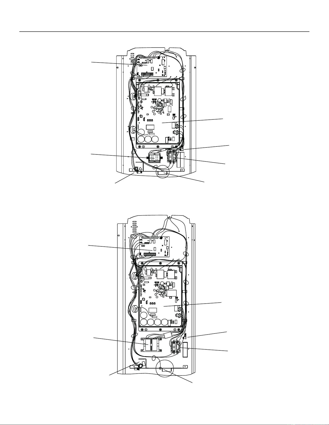
Typical Unit Part Arrangement
Control Panel - 036
OUTDOOR
CONTROL
INVERTER
REACTOR
DC INVERTER
CONTROL
GROUND LUG
OUTDOOR TEMPERATURE
SENSOR
CONTACTOR –
SPST
LOW VOLTAGE
MAKE-UP BOX
Control Panel - 060
OUTDOOR
CONTROL
INVERTER
REACTOR
DC INVERTER
CONTROL
GROUND LUG
CONTACTOR –
SPST
OUTDOOR TEMPERATURE
SENSOR
LOW VOLTAGE
MAKE-UP BOX
Figure 1. Control Panel Components
10
31-5000950 Rev. 0
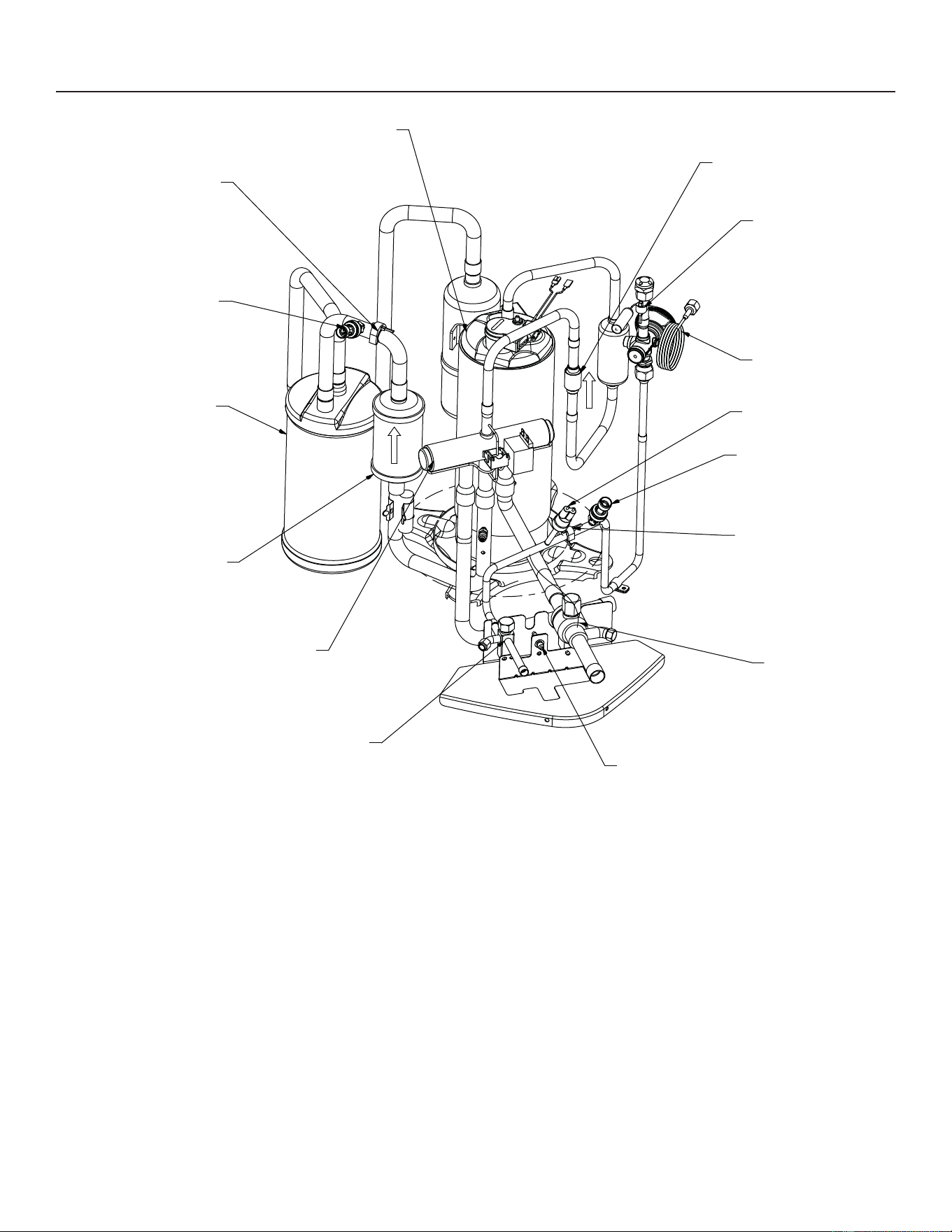
Service Information
VARIABLE CAPACITY
ROTARY COMPRESSOR
SUCTION TEMPERATURE
SENSOR
SUCTION PRESSURE
TRANSDUCER
ACCUMULATOR
SUCTION
FILTER
DRYER
REVERSING VALVE
LIQUID
SERVICE VALVE
COMMON SUCTION
SERVICE PORT
VAPOR
SERVICE VALVE
LIQUID TEMPERATURE
SENSOR
LIQUID PRESSURE
TRANSDUCER
HIGH PRESSURE
SWITCH
OUTDOOR EXPANSION
VALVE
DEFROST
COIL SENSOR
DISCHARGE
CHECK VALVE
Figure 2. Component Locations
11
31-5000950 Rev. 0
Service Information
Operating Gauge Set and Service Valves
Torque Requirements
:KHQVHUYLFLQJRUUHSDLULQJKHDWLQJYHQWLODWLQJDQG
DLUFRQGLWLRQLQJFRPSRQHQWVHQVXUHWKHIDVWHQHUVDUH
appropriately tightened. Table 1 lists torque values for
fasteners.
IMPORTANT
2QO\XVH$OOHQZUHQFKHVRIVXႈFLHQWKDUGQHVV5F
Rockwell Harness Scale minimum). Fully insert the
wrench into the valve stem recess.
• Service valve stems are factory-torqued (from 9 ft-lbs
IRUVPDOOYDOYHVWRIWOEVIRUODUJHYDOYHVWRSUHYHQW
refrigerant loss during shipping and handling. Using an
Allen wrench rated at less than 50Rc risks rounding
RUEUHDNLQJRႇWKHZUHQFKRUVWULSSLQJWKHYDOYHVWHP
recess.
IMPORTANT
7RSUHYHQWVWULSSLQJRIWKHYDULRXVFDSVXVHGWKH
DSSURSULDWHO\VL]HGZUHQFKVKRXOGEHXVHGDQG¿WWHG
snugly over the cap before tightening.
Table 1. Torque Requirements
Parts Recommended Torque
Service valve cap 8 ft.- lb. 11 NM
Sheet metal screws 16 ft.- lb. 2 NM
Machine screws #10 28 ft.- lb. 3 NM
Compressor bolts 90 in.- lb. 10 NM
Gauge port seal cap 8 ft.- lb. 11 NM
USING MANIFOLD GAUGE SET
:KHQFKHFNLQJWKHV\VWHPFKDUJHRQO\XVHDPDQLIROG
JDXJHVHWWKDWIHDWXUHVORZORVVDQWLEORZEDFN¿WWLQJV
Manifold gauge set used with R454B refrigerant systems
must be capable of handling the higher system operating
pressures. The gauges should be rated for use with
pressures of 0 - 800 psig on the high side and a low side
of 30” vacuum to 250 psig with dampened speed to 500
psi. Gauge hoses must be rated for use up to 800 psig of
pressure with a 4000 psig burst rating.
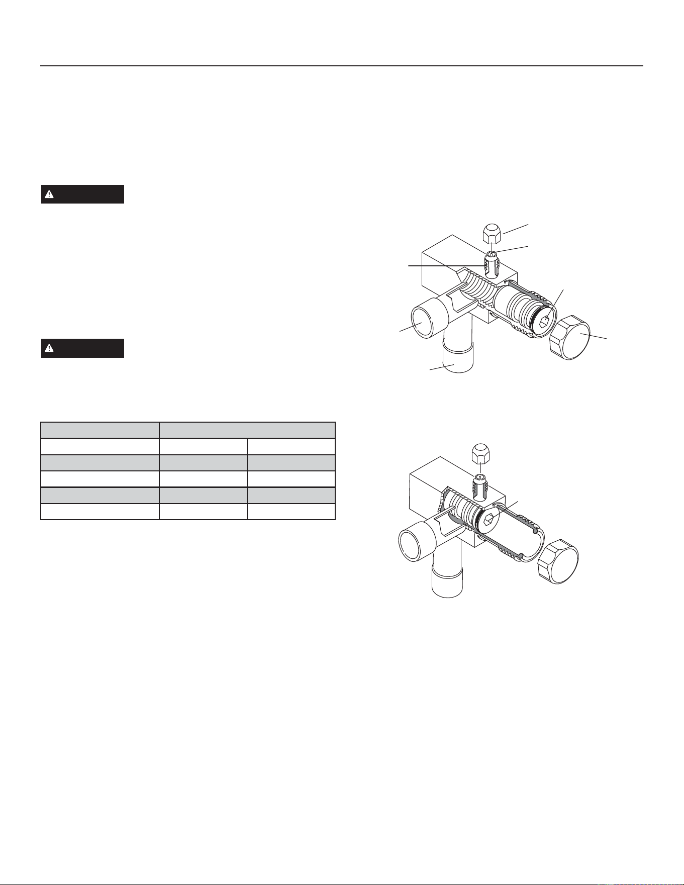
OPERATING SERVICE VALVES
The liquid and vapor line service valves are used for
removing UHIULJHUDQWÀXVKLQJOHDNWHVWLQJHYDFXDWLQJ
checking charge and charging. Each valve is equipped
with a service port which has a factory-installed valve stem.
Figure 4 provides information on access and operation of
both angle and ball service valves.
Service Valves - Angle And Ball
Operating Angle Type Service Valve:
1. Remove stem cap with an appropriately sized wrench.
2. Use a service wrench with a hex-head extension (3/16”
for liquid line valve sizes and 5/16” for vapor line valve
sizes) to back the stem out counterclockwise as far as it
will go.
Service Port Cap
Service Port Core
Stem Cap
(Valve stem shown open)
Insert hex wrench here
Service
Port Core
To Outdoor Unit
To Indoor
Unit
Angle-Type Service Valve (Back-Seated Opened)
When service valve is OPENWKHVHUYLFHSRUWLVRSHQWR
OLQ(VHWLQGRRUDQGRXWGRRUXQLW
(Valve stem shown
CLOSED) Insert hex
wrench here
Angle-Type Service Valve (Front-Seated Closed)
When service valve is CLOSEDWKHVHUYLFHSRUWLVRSHQWR
the line set and indoor unit.
Figure 3. Angle and Ball Service Valves
12
31-5000950 Rev. 0
Service Information
Operating Gauge Set and Service
Valves (cont)
Service Valves - Angle And Ball (cont)
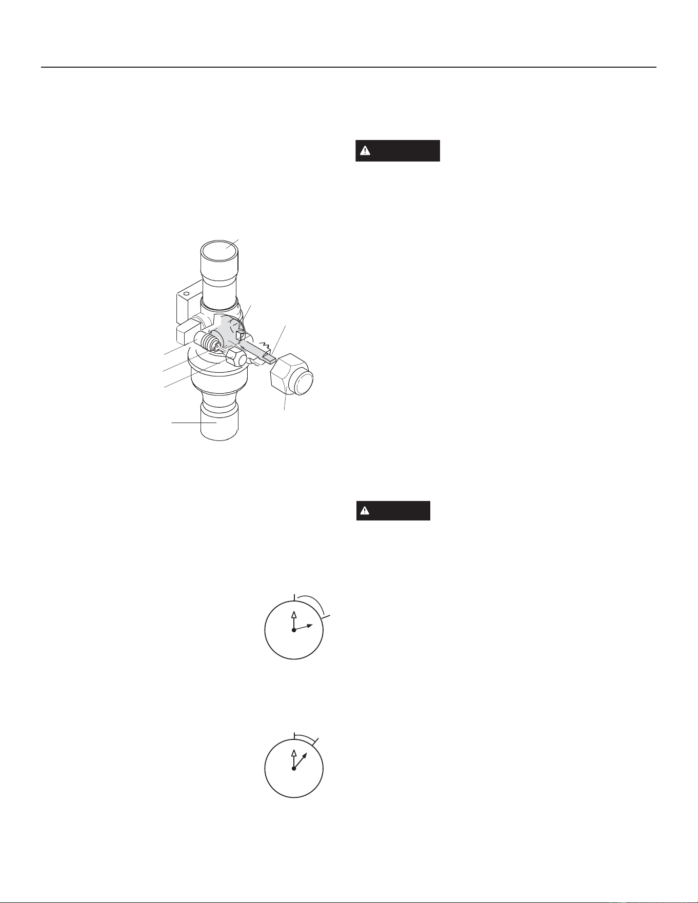
Operating Ball Type Service Valve:
1. Remove stem cap with an appropriately sized wrench.
2. Use an appropriately sized wrenched to open.
– To OPENYDOYHURWDWHVWHPFRXQWHUFORFNZLVH
– To CLOSEURWDWHVWHPFORFNZLVH
Ball (Shown
Closed)
Service Port Core
To Indoor Unit
To Outdoor Unit
To OPEN, rotate stem
counterclockwise 90°.
To CLOSE, rotate stem
clockwise 90°.
Service Port
Service Port Cap
Stem Cap
Valve
Stem
Figure 3. Angle and Ball Service Valves
To Access Service Port:
A service port cap protects the service port core from
contamination and serves as the primary leak seal.
1. Remove service port cap with an appropriately sized
wrench.
2. Connect gauge set to service port.
:KHQWHVWLQJLVFRPSOHWHGUHSODFHVHUYLFHSRUWFDSDQG
tighten as follows:
• With torque wrench: Finger tighten
and torque cap per Table 3.
• Without torque wrench: Finger
tighten and use an appropriately sized
wrench to turn an additional 1/6 turn
clockwise.
Reinstall Stem Cap:
Stem cap protects the valve stem from damage and serves
as the primary seal. Replace the stem cap and tighten as
follows:
• With Torque Wrench: Finger tighten
and then torque cap per Table 3.
• Without Torque Wrench: Finger
tighten and use an appropriately sized
wrench to turn an additional 1/12 turn
clockwise.
NOTE²$ODEHOZLWKVSHFL¿FWRUTXHUHTXLUHPHQWVPD\
EHDႈ[HGWRWKHVWHPFDS,IWKHODEHOLVSUHVHQWXVHWKH
VSHFL¿HGWRUTXH
Unit Placement
See Unit Dimensions on Page 8IRUVL]LQJPRXQWLQJVODE
platforms or supports.
CAUTION
,QRUGHUWRDYRLGLQMXU\WDNHSURSHU
precautions when lifting heavy objects.
POSITIONING CONSIDERATIONS
Consider the following when positioning the unit:
• Some localities are adopting sound ordinances based
on the unit’s sound level registered from the adjacent
SURSHUW\QRWIURPWKHLQVWDOODWLRQSURSHUW\,QVWDOOWKHXQLW
as far as possible from the property line.
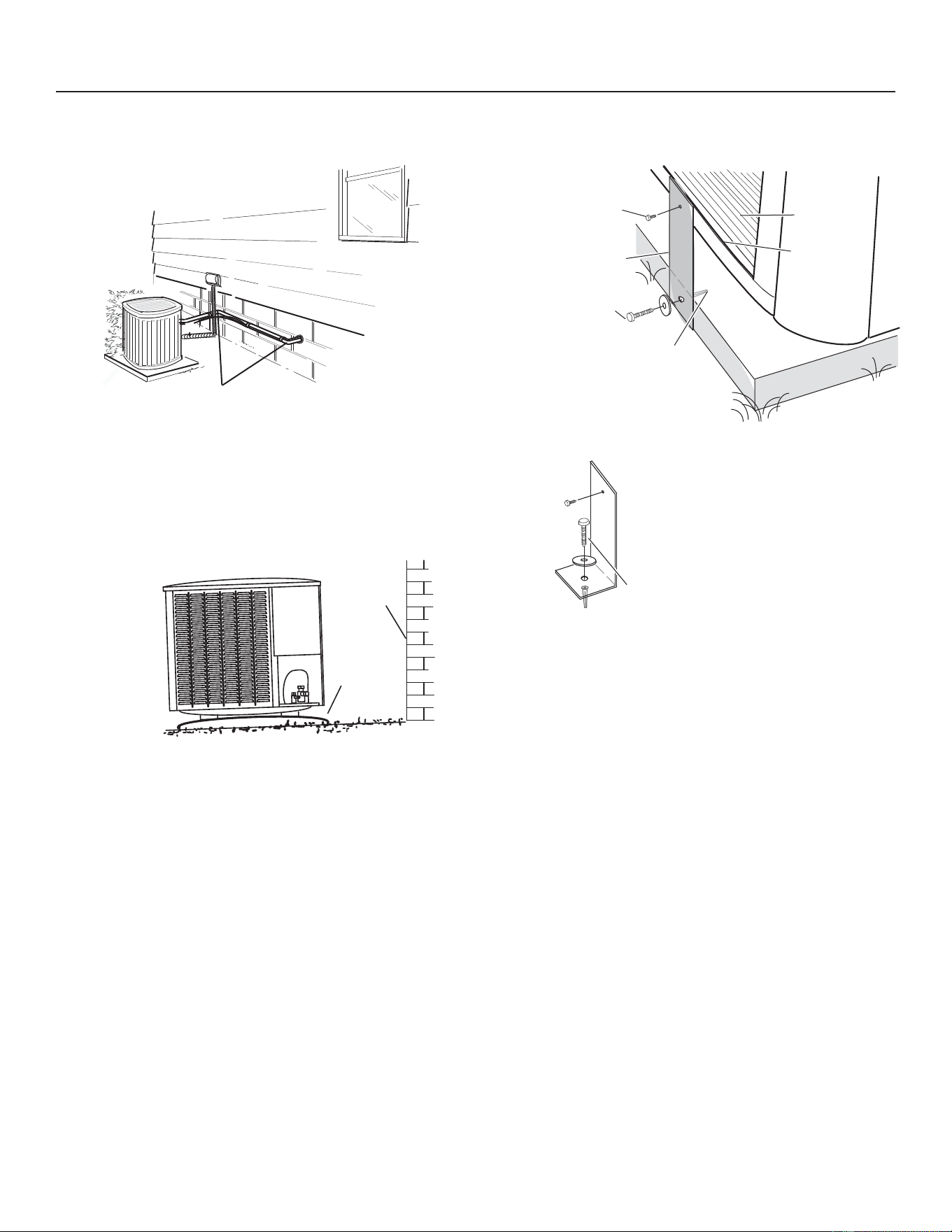
:KHQSRVVLEOHGRQRWLQVWDOOWKHXQLWGLUHFWO\RXWVLGH
a window. Glass has a very high level of sound
transmission. For proper placement of unit in relation to a
ZLQGRZVHHWKHSURYLGHGLOOXVWUDWLRQLQ¿JXUHGHWDLO$
PLACING UNIT ON SLAB
:KHQLQVWDOOLQJXQLWDWJUDGHOHYHOWKHWRSRIWKHVODE
should be high enough above grade so that water from
higher ground will not collect around the unit. The slab
VKRXOGKDYHDVORSHWROHUDQFHDVGHVFULEHGLQ¿JXUH
detail B.
NOTE±,IQHFHVVDU\IRUVWDELOLW\DQFKRUXQLWWRVODEDV
described in Figure 5, Detail D.
ELEVATING THE UNIT
CAUTION
• Accumulation of water and ice in base pan may cause
equipment damage.
Elevate unit per local climate and code requirements to
provide clearance above estimated snowfall level and
ensure adequate drainage of unit. Use snow stand in areas
where prolonged freezing temperatures are encountered.
If conditions or local codes require the unit be attached to
SDGRUPRXQWLQJIUDPHWLHGRZQEROWVVKRXOGEHXVHGDQG
fastened through knockouts provided in unit base pan.
1
2
3
4
5
6
7
8
9
10
11
12
1/12 TURN
1
2
3
4
5
6
7
8
9
10
11
12
1/6 TURN
13
31-5000950 Rev. 0
Service Information
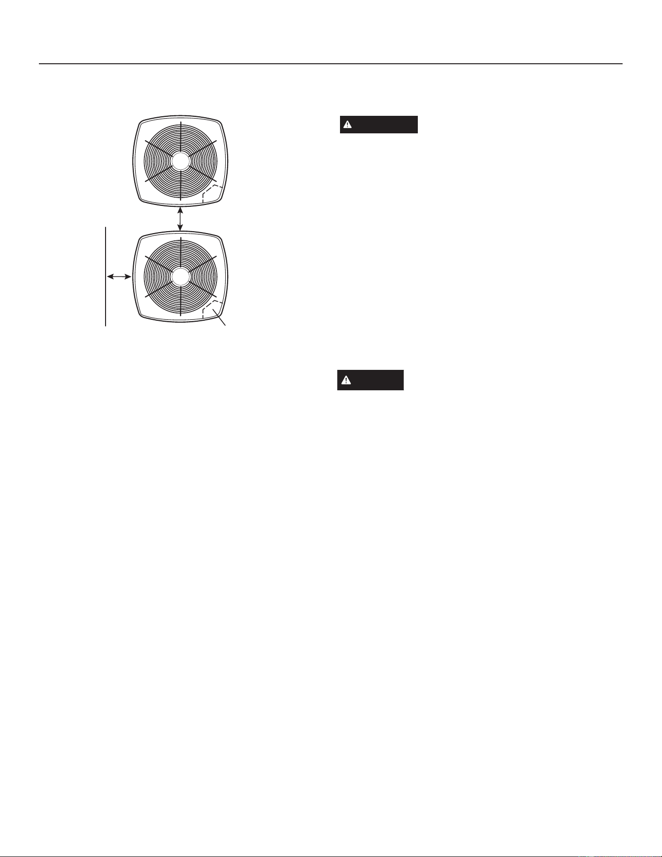
Unit Placement (cont)
30” around
Control
Box
24”
6”*
Figure 4. Installation Clearances
NOTES:
• Service clearance of 30” must be maintained on one of
the sides adjacent to the control box.
• Clearance to one of the other three sides must be 36”.
• Clearance to one of the remaining two sides may be 12”
DQGWKH¿QDOVLGHPD\EHLQ
• A clearance of 24” must be maintained between two units.
• 48” clearance required on top of unit.
NOTE±6SHFL¿FDSSOLFDWLRQVPD\UHTXLUHDGMXVWPHQWRI
the listed installation clearances to provide protection for
the unit from physical damage or to avoid conditions which
OLPLWRSHUDWLQJHႈFLHQF\Example: Clearances may have
to be increased to prevent snow or ice from falling on the
top of the unit. Additional clearances may also be required
to prevent air recirculation when the unit is installed under a
deck or in another tight space.)
STABILIZING UNIT ON UNEVEN SURFACES
IMPORTANT
8QLW6WDELOL]HU%UDFNHW8VH¿HOGSURYLGHG
– Always use stabilizers when unit is raised above the
factory height. (Elevated units could become unstable
in gusty wind conditions.)
– Stabilizers may be used on factory height units when
mounted on unstable an uneven surface.
1 - Remove the louvered panel from each side to expose
the unit base.
,QVWDOOWKHEUDFNHWVDVLOOXVWUDWHGLQ¿JXUHGHWDLO'
using conventional practices.
3 - Replace the panels after installation is complete.
ROOF MOUNTING
Locate the unit above a load-bearing wall or area of the
roof that can adequately support the unit. Consult local
codes for rooftop applications.
NOTICE
Roof Damage!
• This system contains both refrigerant and oil. Some
UXEEHUURR¿QJPDWHULDOPD\DEVRUERLOFDXVLQJWKHUXEEHU
WRVZHOO%XEEOHVLQWKHUXEEHUURR¿QJPDWHULDOFDQFDXVH
leaks. Protect the roof surface to avoid exposure to
refrigerant and oil during service and installation. Failure
to follow this notice could result in damage to roof surface.
14
31-5000950 Rev. 0
Service Information
A.
Install unit away from windows
7ZRHOERZVLQVWDOOHGLQOLQH
set will reduce line set vibration.
Outside Unit Placement
B.
,QVWDOOXQLWOHYHORULIRQDVORSHPDLQWDLQVORSHWROHUDQFH
of 2º (or 2” per 5 ft [50 mm per 1.5 M]) away from building
structure.
Ground Level
Building
Structure
Mounting
Slab
Slab Mounting at Ground Level
C.
Slab Side Mounting
Corner Post
Base Pan
Coil
#10 1/2” Long self-drilling
sheet metal screws
#10 1-1/4” Long hex head
VFUHZDQGÀDWZDVKHU
Stabilizing Bracket (18
gauge metal — 2” width;
height as required)
Concrete Slab — use two
plastic anchors (hole drill 1/4”)
Wood or Plastic Slab — no
plastic anchor (hole drill 1/8”)
Deck Top Mounting
Same fasteners as slab
side mounting
Stabilizing Bracket (18 gauge metal
— 2” (50.8mm) width; height as
required); bend to form right angle.
2QHEUDFNHWSHUVLGHPLQ)RUH[WUDVWDELOLW\WZREUDFNHWV
SHUVLGH´PPIURPHDFKFRUQHU
Stabilizing Unit on Uneven Surfaces
IMPORTANT: 7RKHOSVWDELOL]HDQRXWGRRUXQLWVRPH
installations may require strapping the unit to the pad
using brackets and anchors commonly available in the
marketplace.
Figure 5. Placement and Slab Mounting
15
31-5000950 Rev. 0
Service Information
NEW OR REPLACEMENT LINE SET
IMPORTANT
If this unit is being matched with an approved line set
WKDWZDVSUHYLRXVO\FKDUJHGZLWKPLQHUDORLOWKHOLQHVHW
PXVWEHÀXVKHGSULRUWRLQVWDOODWLRQ7DNHFDUHWRHPSW\DOO
existing traps. Polyvinyl ether (PVE) oils are used in GE
Appliances units charged with R-454B refrigerant. Residual
PLQHUDORLOFDQDFWDVDQLQVXODWRUSUHYHQWLQJSURSHUKHDW
transfer. It can also clog the expansion device and reduce
V\VWHPSHUIRUPDQFHDQGFDSDFLW\)DLOXUHWRSURSHUO\ÀXVK
the system per this instruction and the detailed Installation
and Service Procedures manual will void the warranty.
Flush the existing line set per the following instructions. For
PRUHLQIRUPDWLRQUHIHUWRWKH,QVWDOODWLRQ,QVWUXFWLRQPDQXDO
available on GEAppliancesAirandWater.com.
CAUTION
DO NOTDWWHPSWWRÀXVKDQGUHXVH
existing line sets or indoor coil when the system contains
FRQWDPLQDQWVLHFRPSUHVVRUEXUQRXW
Polyvinyl ether (PVE) oil is used in the unit.
,IDQHZOLQHVHWLVEHLQJLQVWDOOHGVL]HWKHSLSLQJSHUWKH
table below.
Table 2.
REFRIGERANT LINE SET – INCHES (MM)
Model
Valve Field Connections Recommended Line Set
Liquid Line Vapor Line Liquid Line Vapor Line
-036 3/8” (10 mm) 7/8” (22 mm) 3/8” (10 mm) 7/8” (22 mm)
-060 3/8” (10 mm)
1-1/8”
(28 mm)
3/8” (10 mm)
1-1/8”
(28 mm)
NOTE6RPHDSSOLFDWLRQVPD\UHTXLUHD¿HOGSURYLGHGWRDGDSWHU
NOTE - When installing refrigerant lines longer
WKDQIHHWUHIHUWRWKH5HIULJHUDQW3LSLQJ'HVLJQ
and Fabrication Guidelines manual available on
GEAppliancesAirandWater.comRUFRQWDFWWKH7HFKQLFDO
Support Department Product Application group for
assistance.
Line Set Joints - Furnace Application
Evaporator primary line set joints in all applications shall
have a line set joint sleeve.
Evaporator primary line sets should not have additional
joints not covered by line set joint sleeve.
If additional joints are presentWKHV\VWHPLQVWDOODWLRQ
shall comply with one of the options below:
Option 1 - Furnace is installed as a direct vent appliance;
Option 2 - Furnace/Evaporator installation is in a space
greater than the minimum conditioned area (Amin);
Option 3 - Furnace/Evaporator installation is connected to
a space greater than the minimum conditioned area (Amin)
through an opening of at least 15 in² (4-inch diameter hole
equivalent) located below the level of the furnace burners;
Option 4 - Have a second refrigerant detection sensor
installed below the level of the burners (see Secondary
Sensor Installation section).
Multiple Systems Installed in Same Space
For any A2L refrigerant system with additional joints not
FRYHUHGE\OLQHVHWMRLQWVOHHYHVHDFKV\VWHPLQWKHVDPH
space must have refrigerant detection sensor installed
below the level of the burners (see Secondary Sensor
Installation section). If all the systems in the same space
DUHLQVWDOOHGZLWKGLUHFWYHQWDSSOLFDWLRQWKHQDGGLWLRQDO
refrigerant detection sensor is not needed.
Secondary Sensor Installation
,IVHFRQGDU\UHIULJHUDQWVHQVRULVUHTXLUHGLWVKDOOEH
mounted as follows:
8SÀRZ$SSOLFDWLRQV Mounted on an unused side furnace
UHWXUQDLUFRQQHFWLRQDWOHDVWLQFKHVDERYHWKHÀRRUDQG
within 9 inches from front of furnace.
'RZQÀRZ$SSOLFDWLRQV Mounted on one side of the
HYDSRUDWRUFRLOLQFKHVDERYHWKHÀRRUDQGZLWKLQLQFKHV
from front of coil.
Horizontal Applications: Mounted on the bottom side
return furnace air connection within 9 inches of both the
blower deck and front of furnace.
Connect the refrigerant sensor to the second sensor input
on the RDS Control. Refer to the instructions provided
with the sensor or the RDS controller to enable the second
sensor.
WARNING
When using a high pressure gas such as nitrogen to
SUHVVXUL]HDUHIULJHUDWLRQRUDLUFRQGLWLRQLQJV\VWHP
use a regulator that can control the pressure down
to 1 or 2 psig (6.9 to 13.8 kPa).
• Refrigerant must be used and recovered responsibly.
• Failure to follow this warning may result in personal injury
or death.
16
31-5000950 Rev. 0
Service Information
NEW OR REPLACEMENT LINE SET
WARNING
• Fire, Explosion and Personal Safety hazard.
Failure to follow this warning could result in
GDPDJHSHUVRQDOLQMXU\RUGHDWK
• Never use oxygen to pressurize or purge
UHIULJHUDWLRQOLQHV2[\JHQZKHQH[SRVHGWRD
VSDUNRURSHQÀDPHFDQFDXVH¿UHDQGRUDQ
H[SORVLRQWKDWFRXOGUHVXOWLQSURSHUW\GDPDJH
personal injury or death.
• Polyvinyl ether (PVE) oils used with R-454B refrigerant
absorb moisture very quickly. It is very important that the
refrigerant system be kept closed as much as possible.
DO NOT remove line set caps or service valve stub caps
until you are ready to make connections.
The NS19H is a variable-capacity cooling system utilizing
variable speed compressor technology. With the variable
VSHHGFRPSUHVVRUDQGYDULDEOHSXPSLQJFDSDFLW\
additional consideration must be given to refrigerant piping
sizing and application. The guidelines below are to be used
exclusively for the NS19H systems.
COOLING SYSTEM (R454B)
• Total equivalent length equals 180 ft (piping and all ¿WWLQJV
included).
NOTE – Length is general guide. Lengths may be more or
OHVVGHSHQGLQJRQUHPDLQLQJV\VWHPGHVLJQIDFWRUV
• Maximum linear (actual) length = 150 ft.
• Maximum linear liquid lift = 60 ft.
NOTE±0D[LPXPOLIWVDUHGHSHQGHQWRQWRWDOOHQJWK
QXPEHURIHOERZVHWFWKDWFRQWULEXWHWRWRWDOSUHVVXUH
drop.
• Maximum length vapor riser = 60 feet.
• Up to 50 Linear Feet: Use rated line sizes listed in
Table 3.
• Between 51 and 150 Linear Feet: Crankcase heater
and nonbleed port TXV factory installed. No additional
components required. Vertical vapor riser must be sized
to the vapor riser listed in the table 4 on systems with
line sets longer than 51 ft. Use Table 3 and Table 4 to
determine the correct liquid and vapor line sizes.
• Over 150 Linear Feet: not recommended.
• Additional oil is not required for systems with line lengths
up to 150 feet.
SUCTION TRAPS
For systems with the outdoor unit 5 - 60 feet above the
LQGRRUXQLWRQHWUDSPXVWEHLQVWDOOHGDWWKHERWWRPRIWKH
suction riser.
Table 3. Standard Refrigerant Line Set – Up to 50 Linear Feet in Length - Inches (mm)
Valve Size Connections Recommended Line Sets
NS19H Liquid LIne Suction Line L15 Line Set Model Line Set Length Catalog Number
-036 3/8” (10 mm) 7/8” (22 mm) L15-65-50 40 feet (12.2 m) -
-060 3/8” (10 mm) 1-1/8” (29 mm) ** Field-fabricated
$SSOLFDEOHWRDOOPLQRUUHYLVLRQQXPEHUVXQOHVVRWKHUZLVHVSHFL¿HG
6RPHDSSOLFDWLRQVPD\UHTXLUHD¿HOGSURYLGHG´WR´DGDSWHU
Table 4. NS19H Line Set Guidelines – 51 to 150 Linear Feet in Length
Model
Maximum Total
Equivalent
Length (ft)
Maximum Linear
(actual) Length
(ft)
Maximum Vapor
Riser (ft)
Maximum Linear
Liquid Lift (ft)
Preferred Vapor
Line Sizes for
Horizontal Runs
Required Vapor
Riser Size
-036 180 150 60 60 7/8” 3/4”
-060 180 150 60 60 7/8” 7/8”
Table 5. Liquid Line Diameter Selection Table
Unit Line Size
Total Linear Length (ft)
25 50 75 100 125 150
Max.
Elevation (ft)
-036
3/8” 25 50 60 56 51 45
1/2” 25 50 60 60 60 60
-060
3/8” 25 50 36 22 8 NR
1/2” 25 50 30 60 60 59
NOTE - Shaded rows indicate rated liquid line size.
A. Find your unit on the left side of the table.
B. Start with the rated liquid line size (shaded row) on the outdoor unit
C. Select the actual Total Linear Length of your system shown at the top of the table.
D. The elevation listed in the table is the maximum allowed for the liquid line listed.
E. Select or consider the larger liquid line size shown in the table if the elevation does not meet your requirements.
NOTE)RUQHZRUUHSODFHPHQWOLQHVHWLQVWDOODWLRQUHIHUWR*($SSOLDQFHV5HIULJHUDQW3LSLQJ*XLGHOLQHV
17
31-5000950 Rev. 0
Service Information
LINE SET
IMPORTANT
Refrigerant lines must not contact structure.
INSTALLATION
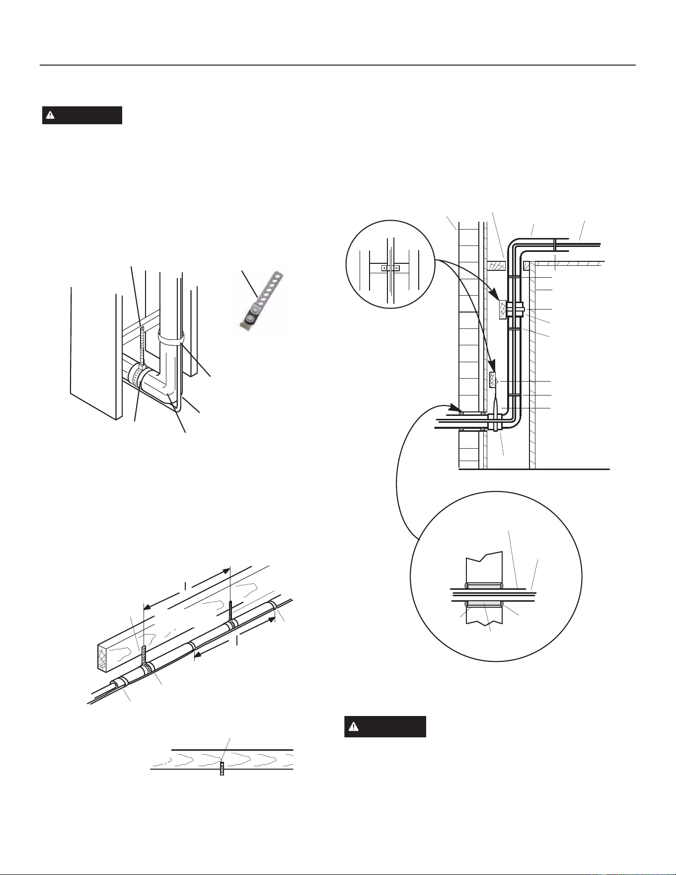
Line Set Isolation — The following illustrations are
examples of proper refrigerant line set isolation:
REFRIGERANT LINE SET — TRANSITION FROM
VERTICAL TO HORIZONTAL
Anchored Heavy Nylon Wire Tie or
$XWRPRWLYH0XႉHU7\SH+DQJHU
$XWRPRWLYH0XႉHU
Type Hanger
Non-Corrosive
Metal Sleeve
Strap Liquid Line
to Vapor Line
Liquid line
Vapor Line -
:UDSSHG,Q$UPDÀH[
Wall
Stud
REFRIGERANT LINE SET — INSTALLING HORIZONTAL
RUNS
7RKDQJOLQHVHWIURPMRLVWRUUDIWHUXVHHLWKHUPHWDO
strapping material or anchored heavy nylon wire ties.
8 ft (2.43 m)
Wire Tie (around
Vapor Line only)
Tape or
Wire Tie
8 ft (2.43 m)
)ORRU-RLVWRU
Roof Rafter
Strapping Material
(around Vapor Line only)
6WUDS7KH9DSRU/LQH7R7KH-RLVW
Or Rafter At 8 Feet (2.43 Meters)
Intervals Then Strap The Liquid
Line To The Vapor Line.
)ORRU-RLVWRU5RRI5DIWHU
Non-Corrosive Metal Sleeve
Tape or
Wire Tie
REFRIGERANT LINE SET — INSTALLING
VERTICAL RUNS (NEW CONSTRUCTION SHOWN)
NOTE — Insulate liquid line when it is routed through areas
where the surrounding ambient temperature could become
higher than the temperature of the liquid line or when
pressure drop is equal to or greater than 20 psig.
Outside Wall
Vapor Line
Liquid Line
Wire Tiel
Inside Wall
Strap
Non-Corrosive
Metal Sleeve
Wire Tie
Wood Block
Wire Tie
Strap
Sleeve
Wood Block Between Studs
Vapor Line Wrapped
:LWK$UPDÀH[
Liquid Line
Fiberglass
Insulation
Caulk
PVC Pipe
Outside Wall
NOTE — Similar installation practices should be used if line
set is to be installed on exterior of outside wall.
WARNING
Polyol ester (POE) oils used with HFC-
410A refrigerant absorb moisture very quickly. It is very
important that the refrigerant system be kept closed as
much as possible. DO NOT remove line set caps or service
valve stub caps until you are ready to make connections.
Figure 7. Line Set Installation
18
31-5000950 Rev. 0
Service Information
BRAZING CONNECTIONS
Use the procedures outlined in Figures 8 and 9 for brazing
line set connections to service valves.
WARNING
'DQJHURI¿UH%OHHGLQJWKHUHIULJHUDQWFKDUJHIURP
only the high side may result in pressurization of
the low side shell and suction tubing. Application of
a brazing torch to a pressurized system may result
in ignition of the refrigerant and oil mixture. Check
the high and low pressures before applying heat.
• When using a high pressure gas such as nitrogen
to pressurize a refrigeration or air conditioning
V\VWHPXVHDUHJXODWRUWKDWFDQFRQWUROWKH
pressure down to 1 or 2 psig (6.9 to 13.8 kPa).
Refrigerant can be harmful if it is inhaled.
)LUH([SORVLRQDQG3HUVRQDO6DIHW\KD]DUG)DLOXUH
WRIROORZWKLVZDUQLQJFRXOGUHVXOWLQGDPDJH
personal injury or death.
• Never use oxygen to pressurize or purge
UHIULJHUDWLRQOLQHV2[\JHQZKHQH[SRVHGWRD
VSDUNRURSHQÀDPHFDQFDXVH¿UHDQGRUDQ
H[SORVLRQWKDWFRXOGUHVXOWLQSURSHUW\GDPDJH
personal injury or death.
CAUTION
%UD]LQJDOOR\VDQGÀX[FRQWDLQPDWHULDOVZKLFKDUH
hazardous to your health.
• Avoid breathing vapors or fumes from brazing operations.
Perform operations only in well-ventilated areas.
• Wear gloves and protective goggles or face shield to
protect against burns.
• Wash hands with soap and water after handling brazing
DOOR\VDQGÀX[
IMPORTANT
• Allow braze joint to cool before removing the wet rag from
the service valve. Temperatures above 250ºF can damage
valve seals.
• Use silver alloy brazing rods with 5% minimum silver alloy
for copper-to-copper brazing. Use 45% minimum alloy for
copper-to-brass and copper-to-steel brazing.
19
31-5000950 Rev. 0
Service Information
Brazing Procedures
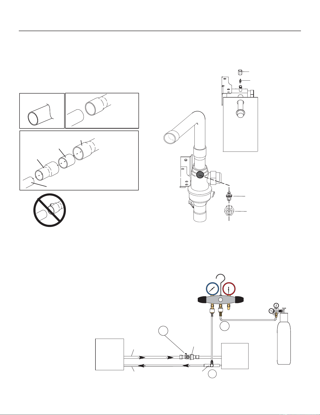
1. PIPING PANEL REMOVAL AND LINE SET
PREPARATION
Remove piping panel for easier access to service valves.
Cut ends of the refrigerant lines square (free from nicks or
dents) and debur the ends. The pipe must remain round.
Do not crimp end of the line.
Cut and Debur
Line set size matches
service valve connection
Service Valve Connections
Copper Tube Stub
Reducer
Refrigerant Line
Line set size is smaller
than connection
DO NOT crimp service valve
connector when pipe is
smaller than connection
3. ATTACH THE MANIFOLD GAUGE SET FOR BRAZING
LIQUID AND SUCTION LINE SERVICE VALVES
A. Connect gauge set low pressure side to liquid line
service valve (service port).
B. Connect gauge set center port to bottle of nitrogen with
regulator.
C. With valve core removed from the suction line service
SRUWQLWURJHQÀRZZLOOKDYHDQH[LWSRLQW
2. CAP AND CORE REMOVAL
Remove service cap and core from both the suction and
liquid line service ports.
Service Port Cap
Service Port Core
Liquid Line Service Valve
Service
Port Cap
Service
Port Core
Suction Line Service Valve
B
A
C
Suction Service Port must be open
and Service Port Core removed to
DOORZH[LWSRLQWIRUQLWURJHQÀRZ
Indoor
Unit
Outdoor
Unit
Suction Line
Service Valve
Liquid Line
Service Valve
Suction Line
Liquid Line
Nitrogen
HighLow
Attach
Gauges
Figure 8. Brazing Procedures
20
31-5000950 Rev. 0
Service Information
Brazing Procedures (cont)
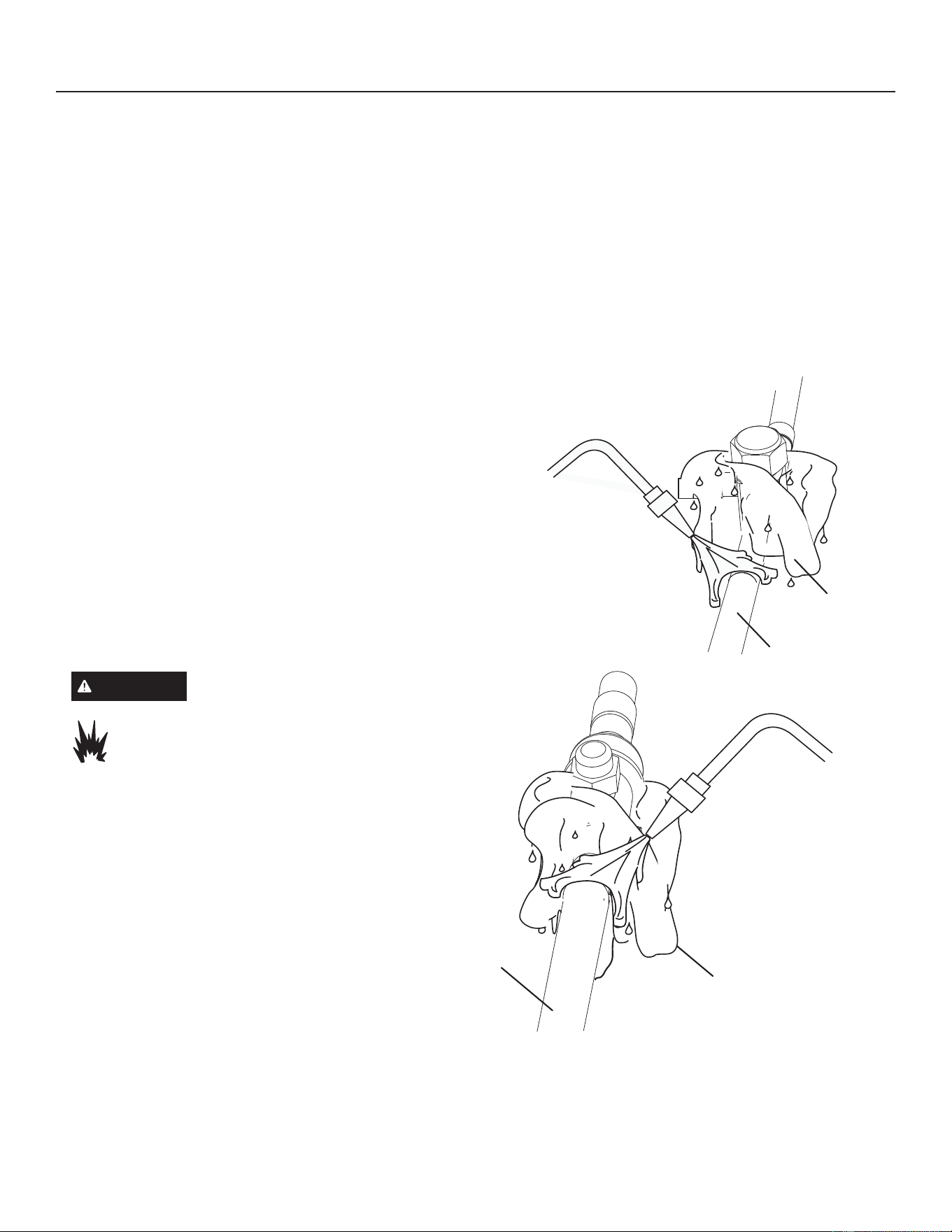
4. WRAP SERVICE VALVES
7RKHOSSURWHFWVHUYLFHYDOYHVHDOVGXULQJEUD]LQJZUDSZDWHUVDWXUDWHGFORWKVDURXQGVHUYLFHYDOYHERGLHVDQGFRSSHU
tube stubs. Use additional water-saturated cloths underneath the valve body to protect the base paint.
5. FLOW NITROGEN
Flow regulated nitrogen (at 1 to 2 psig) through the refrigeration gauge set into the valve stem port connection on the
OLTXLGVHUYLFHYDOYHDQGRXWRIWKHVXFWLRQYDSRUYDOYHVWHPSRUW6HHVWHSV$%DQG&RQPDQLIROGJDXJHVHW
connections.
6. BRAZE LINE SET
:UDSERWKVHUYLFHYDOYHVZLWKZDWHUVDWXUDWHGFORWKVDVLOOXVWUDWHGKHUHDQGDVPHQWLRQHGLQVWHSEHIRUHEUD]LQJWR
line set. Cloths must remain water-saturated throughout the brazing and cool-down process.
Liquid Line Service Valve
Water-Saturated
Cloth
Liquid LIne
When brazing line set to
VHUYLFHYDOYHVSRLQWÀDPH
away from service valve.
IMPORTANT - Allow braze joint to cool. Apply additional
water-saturated cloths to help cool brazed joint. Do not
remove water-saturated cloths until piping has cooled.
Temperatures above 250ºF will damage valve seals.
When brazing line set to
VHUYLFHYDOYHVSRLQWÀDPH
away from service valve.
Suction Line Service Valve
Suction Line
Water-Saturated
Cloth
7. PREPARATION FOR NEXT STEP
Disconnect manifold gauge set from service ports after all connections have been brazed. Apply additional water-
VDWXUDWHGFORWKVWRERWKVHUYLFHYDOYHVWRFRROSLSLQJ2QFHSLSLQJLVFRROUHPRYHDOOZDWHUVDWXUDWHGFORWKV
WARNING
FIRE, PERSONAL INJURY, OR PROPERTY
DAMAGE may result if you do not wrap a
water-saturated cloth around both liquid and
suction line service valve bodies and copper
WXEHVWXEZKLOHEUD]LQJWKHOLQHVHW7KHEUD]H
ZKHQFRPSOHWHPXVWEHTXHQFKHGZLWKZDWHUWR
absorb any residual heat.
Do not open service valves until refrigerant
lines and indoor coil have been leak-
tested and evacuated. Refer to Installation
and Service Procedures manual found on
GEAppliancesAirandWater.com.
Figure 9. Brazing Procedures (cont)
21
31-5000950 Rev. 0
Service Information
Flushing Line Set and Indoor Coil
1A. TYPICAL EXISTING FIXED ORIFICE REMOVAL
PROCEDURE (UNCASED COIL SHOWN)
Distributor Tubes
/LTXLG/LQH2UL¿FH+RXVLQJ
7HÀRQ
®
Ring
)L[HG2UL¿FH
Brass Nut
Liquid Line Assembly
(includes strainer)
Remove and
Discard White
7HÀRQ
®
Seal
(if present)
Distributor
Assembly
$2QIXOO\FDVHGFRLOVUHPRYHWKHFRLODFFHVVDQG
plumbing panels.
B. Remove any shipping clamps holding the liquid line and
distributor assembly.
&8VLQJWZRZUHQFKHVGLVFRQQHFWOLTXLGOLQHIURPOLTXLG
OLQHRUL¿FHKRXVLQJ7DNHFDUHQRWWRWZLVWRUGDPDJH
distributor tubes during this process.
'5HPRYHDQGGLVFDUG¿[HGRUL¿FHYDOYHVWHPDVVHPEO\LI
SUHVHQWDQG7HÀRQ
®
washer as illustrated above.
(8VHD¿HOGSURYLGHG¿WWLQJWRWHPSRUDULO\UHFRQQHFWWKH
OLTXLGOLQHWRWKHLQGRRUXQLWVOLTXLGOLQHRUL¿FHKRXVLQJ
1B. TYPICAL EXISTING FIXED ORIFICE REMOVAL
PROCEDURE (UNCASED COIL SHOWN)
Two Piece Patch Plate
(uncased coil only)
Distributor
Tubes
Liquid Line
2UL¿FH+RXVLQJ
Stub End
Check Expansion Valve
7HÀRQ
®
Ring
7HÀRQ
®
Ring
7HÀRQ
®
Ring
Sensing
LIne
Liquid Line
Assembly with
Brass Nut
Liquid Line
Vapor
Line
Sensing Bulb
Male
Equalizer
Line Fitting
Equalizer
Line
Distributor
Assembly
$2QIXOO\FDVHGFRLOVUHPRYHWKHFRLODFFHVVDQG
plumbing panels.
B. Remove any shipping clamps holding the liquid line and
distributor assembly.
C. Disconnect the equalizer line from the check expansion
YDOYHHTXDOL]HUOLQH¿WWLQJRQWKHYDSRUOLQH
D. Remove the vapor line sensing bulb.
E. Disconnect the liquid line from the check expansion
valve at the liquid line assembly.
F. Disconnect the check expansion valve from the liquid
OLQHRUL¿FHKRXVLQJ7DNHFDUHQRWWRWZLVWRUGDPDJH
distributor tubes during this process.
G. Remove and discard check expansion valve and the two
7HÀRQULQJV
+8VHD¿HOGSURYLGHG¿WWLQJWRWHPSRUDU\UHFRQQHFWWKH
OLTXLGOLQHWRWKHLQGRRUXQLWVOLTXLGOLQHRUL¿FHKRXVLQJ
Figure 10. Removing Metering Device and Flushing
22
31-5000950 Rev. 0
Service Information
Flushing Line Set and Indoor Coil
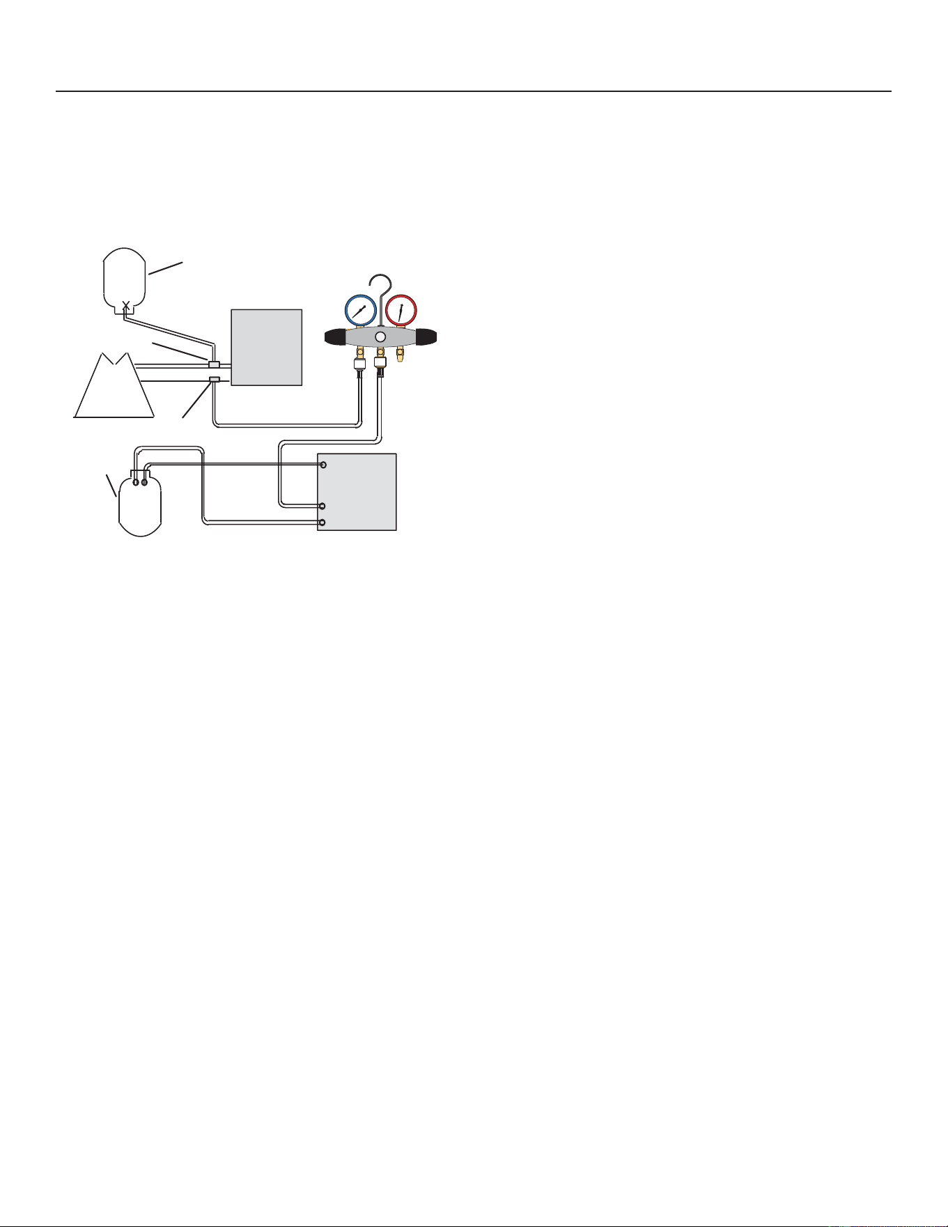
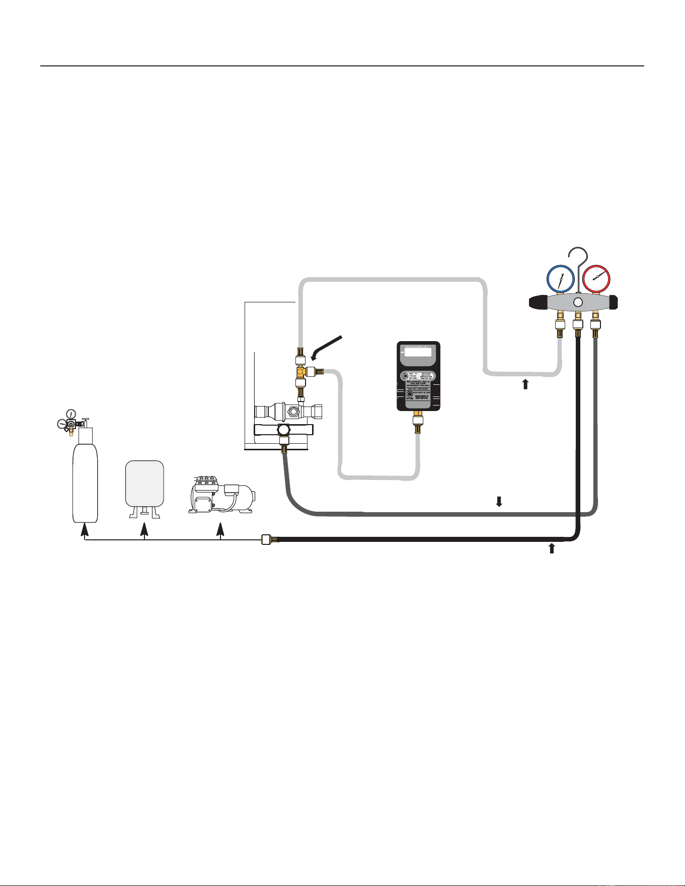
2. CONNECT GAUGES AND EQUIPMENT FOR
FLUSHING PROCEDURE
1
A
B
C
D
Inverted cylinder contains
clean HCFC22* to be used for
ÀXVKLQJ
Gauge
Manifold
HighLow
Closed
Opened
New
Outdoor
Unit
Vapor Line
Service Valve
Existing
Indoor
Unit
Vapor
Liquid
Liquid Line Service Valve
Tank
Return
Inlet
Discharge
Recovery MachineRecovery Cylinder
A. Inverted HCFC-22 cylinder with clean refrigerant* to the
vapor service valve.
B. HCFC-22 gauge set (low side) to the liquid line valve.
C. HCFC-22 gauge set center port to inlet on the recovery
machine with an empty recovery tank to the gauge set.
D. Connect recovery tank to recovery machines per
machine instructions.
3. FLUSHING LINE SET)
7KHOLQHVHWDQGLQGRRUXQLWFRLOPXVWEHÀXVKHGZLWKDW
least the same amount of clean refrigerant* that previously
FKDUJHGWKHV\VWHP&KHFNWKHFKDUJHLQWKHÀXVKLQJ
cylinder before proceeding.
A. Set the recovery machine for liquid recovery and start
the recovery machine. Open the gauge set valves to
allow the recovery machine to pull a vacuum on the
existing system line set and indoor unit coil.
B. Invert the cylinder of clean HCFC-22* and open its valve
WRDOORZOLTXLGUHIULJHUDQWWRÀRZLQWRWKHV\VWHPWKURXJK
the vapor line valve. Allow the refrigerant to pass from
the cylinder and through the line set and the indoor unit
coil before it enters the recovery machine.
&$IWHUDOORIWKHOLTXLGUHIULJHUDQWKDVEHHQUHFRYHUHG
switch the recovery machine to vapor recovery so that all
of the HCFC-22 vapor is recovered. Allow the recovery
machine to pull the system down to 0.
D. Close the valve on the inverted HCFC-22 drum and the
gauge set valves. Pump the remaining refrigerant out of
WKHUHFRYHU\PDFKLQHDQGWXUQWKHPDFKLQHRႇ
*IMPORTANT - Clean refrigerant is any refrigerant in a
system that has not had compressor burn out. If the
system has experienced burn out, it is recommended
that the existing line set and indoor coil be replaced.
Figure 10. Removing Metering Device and Flushing (cont)
23
31-5000950 Rev. 0
Service Information
Flushing Line Set and Indoor Coil
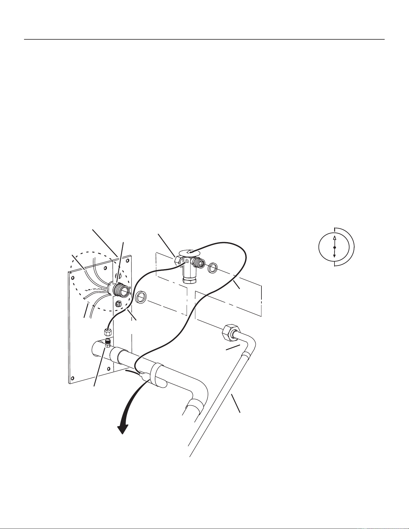
4. TYPICAL NEW CHECK EXPANSION VALVE INSTALLATION PROCEDURE
This outdoor unit is designed for use in systems that use a check expansion valve metering device. See the unit Product
6SHFL¿FDWLRQVIRUDSSURYHGH[SDQVLRQYDOYHNLWPDWFKXSVDQGDSSOLFDWLRQLQIRUPDWLRQ
The expansion valve unit can be installed internal or external to the indoor coil. In applications where an uncased coil is
EHLQJLQVWDOOHGLQD¿HOGSURYLGHGSOHQXPLQVWDOOWKHFKHFNH[SDQVLRQYDOYHLQDPDQQHUWKDWZLOOSURYLGHDFFHVVIRU¿HOG
servicing of the expansion valve. Refer to below illustration for reference during installation of expansion valve unit.
$5HPRYHWKH¿HOGSURYLGHG¿WWLQJWKDWWHPSRUDULO\UHFRQQHFWHGWKHOLTXLGOLQHWRWKHLQGRRUXQLWVGLVWULEXWRUDVVHPEO\
%,QVWDOORQHRIWKHSURYLGHG7HÀRQULQJVDURXQGWKHVWXEEHGHQGRIWKHH[SDQVLRQYDOYHDQGOLJKWO\OXEULFDWHWKHFRQQHFWRU
WKUHDGVDQGH[SRVHVXUIDFHRIWKH7HÀRQ
®
ring with refrigerant oil.
&$WWDFKWKHVWXEEHGHQGRIWKHH[SDQVLRQYDOYHWRWKHOLTXLGOLQHRUL¿FHKRXVLQJ)LQJHUWLJKWHQDQGXVHDQDSSURSULDWHO\
VL]HGZUHQFKWRWXUQDQDGGLWLRQDOWXUQFORFNZLVHDVLOOXVWUDWHGLQWKH¿JXUHDERYHRUIWOE
'3ODFHWKHUHPDLQLQJ7HÀRQ
®
washer around the other end of the expansion valve. Lightly lubricate connector threads and
H[SRVHVXUIDFHRIWKH7HÀRQULQJZLWKUHIULJHUDQWRLO
E. Attach the liquid line assembly to the expansion valve. Finger tighten and use an appropriately sized wrench to turn an
DGGLWLRQDOWXUQFORFNZLVHDVLOOXVWUDWHGLQWKH¿JXUHDERYHRUIWOE
Two piece patch plate
(uncased coil only)
Distributor
Tubes
Liquid Line
2UL¿FH
Housing
Stub End
Expansion
Valve
7HÀRQ
®
Ring
7HÀRQ
®
Ring
Sensing
LIne
Liquid Line
Assembly with
Brass Nut
Liquid Line
Vapor
Line
Male Equalizer Line
Fitting (see equalizer
line installaton for
further details)
Equalizer
Line
Distributor
Assembly
(Uncased Coil Shown)
Sensing bulb insulation is required if
mounted external to the coil casing. See
sensing bulb installation for bulb positioning.
1
2
3
4
5
6
7
8
9
10
11
12
1/2 Turn
Figure 10. Removing Metering Device and Flushing (cont)
24
31-5000950 Rev. 0
Service Information
Flushing Line Set and Indoor Coil
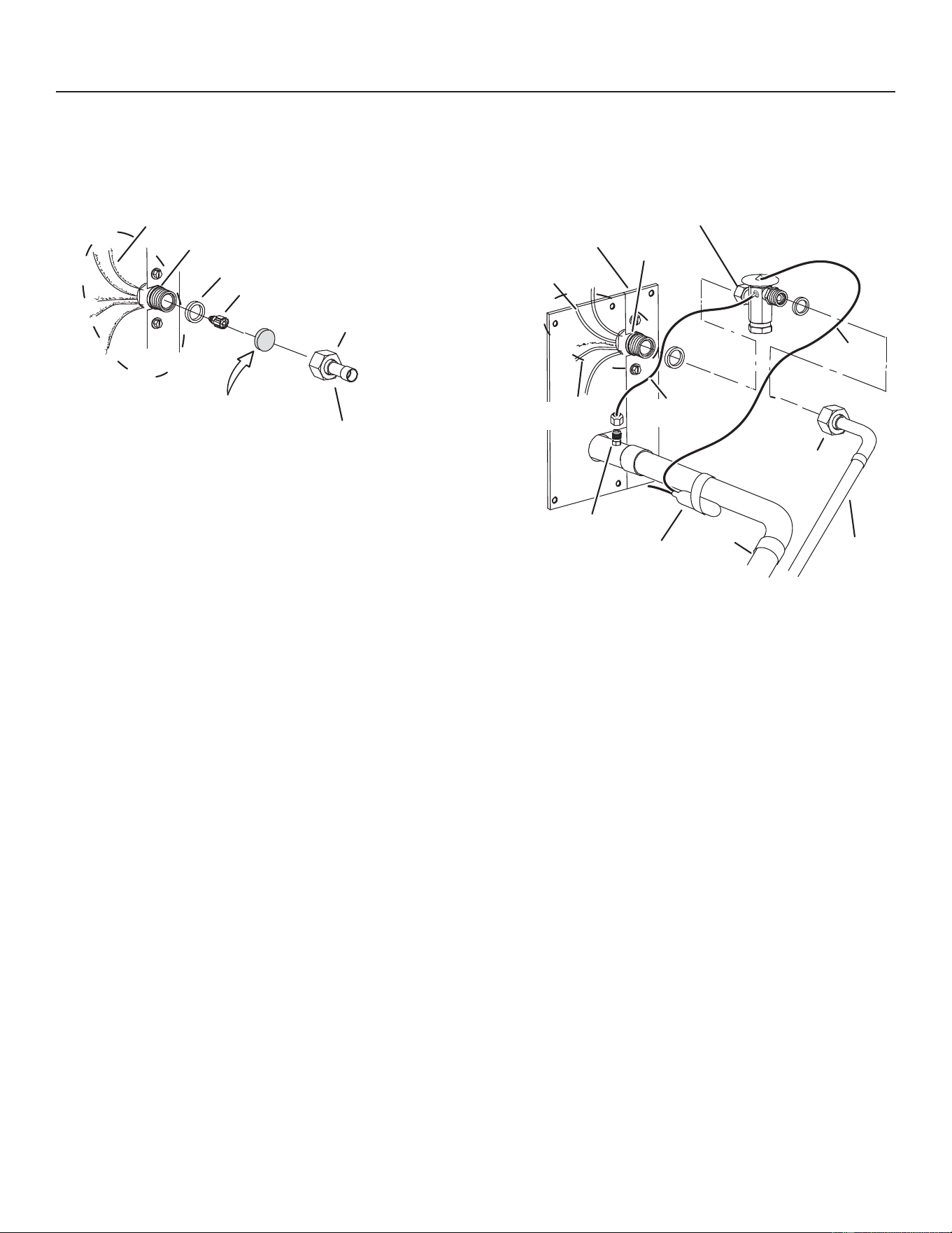
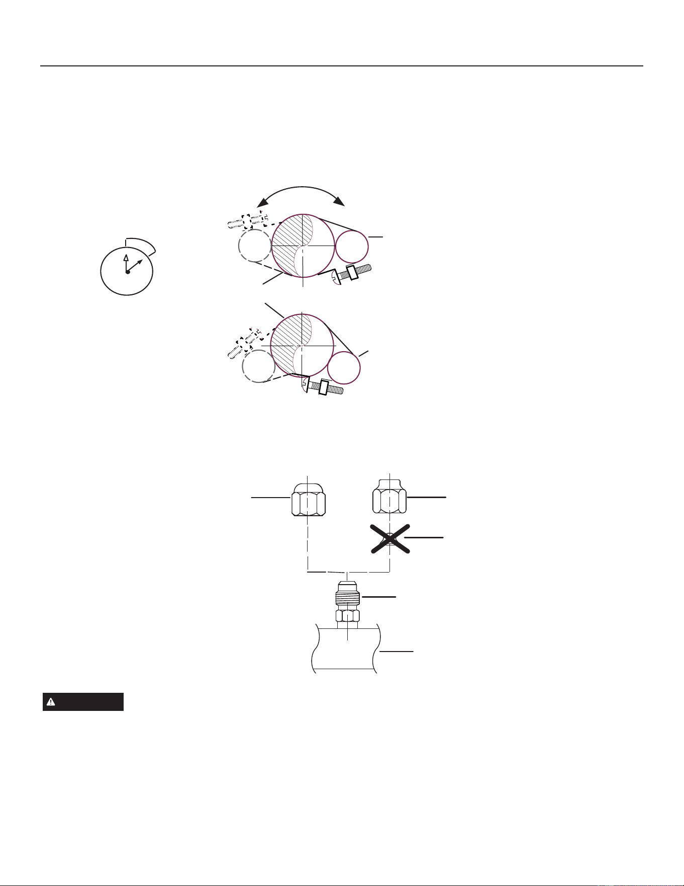
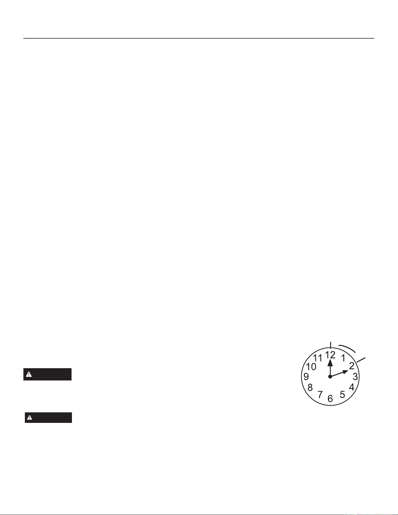
SENSING BULB INSTALLATION
A. Attach the vapor line sensing bulb in the proper orientation as illustrated to the right using the clamp and screws provided.
Note - FRQ¿UPSURSHUWKHUPDOFRQWDFWEHWZHHQYDSRUOLQHDQGFKHFNH[SDQVLRQEXOEEHIRUHLQVXODWLQJWKHVHQVLQJEXOERQFH
installed.
%&RQQHFWWKHHTXDOL]HUOLQHIURPWKHH[SDQVLRQYDOYHWRWKHHTXDOL]HUYDSRUSRUWRQWKHYDSRUOLQH)LQJHUWLJKWHQWKHÀDUH
nut plus 1/8 turn (7 ft-lbs) as illustrated.
12
12
9 o'clock to
3 o'clock
Vapor Line
Vapor Line
Bulb
Bulb
Bulb
Bulb
On lines smaller
WKDQ´PRXQW
sensing bulb
between the 9 and 3
o'clock positions.
2Q´DQGODUJHUOLQHV
mount sensing bulb at
either the 4 or 8 o'clock
position. Never mount
the sensing bulb on
bottom of line.
Note - Never mount the sensing bulb
on bottom of line.
EQUALIZER LINE INSTALLATION
5HPRYHDQGGLVFDUGHLWKHUWKHÀDUHVHDOFDSRUÀDUHQXWZLWKFRSSHUÀDUHVHDOERQQHWIURPWKHHTXDOL]HUOLQHSRUWRQWKH
YDSRUOLQHDVLOOXVWUDWHGLQWKH¿JXUHEHORZ
OR
Flare NutFlare Seal Cap
Copper
Flare Seal
Bonnet
Male Brass Equalizer
Line Fitting
Vapor Line
IMPORTANT
7KH(QYLURQPHQWDO3URWHFWLRQ$JHQF\(3$SURKLELWVWKHLQWHQWLRQDOYHQWLQJRI+)&UHIULJHUDQWVGXULQJPDLQWHQDQFH
VHUYLFHUHSDLUDQGGLVSRVDORIDSSOLDQFH
$SSURYHGPHWKRGVRIUHFRYHU\UHF\FOLQJRUUHFODLPLQJPXVWEHIROORZHG
,IWKLVXQLWLVEHLQJPDWFKHGZLWKDQDSSURYHGOLQHVHWWKDWZDVSUHYLRXVO\FKDUJHGZLWKPLQHUDORLOWKHOLQHVHWPXVWEH
ÀXVKHGSULRUWRLQVWDOODWLRQ7DNHFDUHWRHPSW\DOOH[LVWLQJWUDSV3RO\YLQ\OHWKHU39(RLOVDUHXVHGLQ*($SSOLDQFHV
XQLWVFKDUJHGZLWK5%UHIULJHUDQW5HVLGXDOPLQHUDORLOFDQDFWDVDQLQVXODWRUSUHYHQWLQJSURSHUKHDWWUDQVIHU,WFDQ
DOVRFORJWKHH[SDQVLRQGHYLFHDQGUHGXFHV\VWHPSHUIRUPDQFHDQGFDSDFLW\)DLOXUHWRSURSHUO\ÀXVKWKHV\VWHPSHU
this instruction and the detailed Installation and Service Procedures manual will void the warranty.
1
2
3
4
5
6
7
8
9
10
11
12
1/8 Turn
Figure 10. Removing Metering Device and Flushing (cont)
25
31-5000950 Rev. 0
Service Information
LEAK TESTING THE SYSTEM
WARNING
:KHQXVLQJDKLJKSUHVVXUHJDVVXFKDVQLWURJHQWRSUHVVXUL]HDUHIULJHUDWLRQRUDLUFRQGLWLRQLQJV\VWHPXVHD
regulator that can control the pressure down to 1 or 2 psig (6.9 to 13.8 kPa).
• Refrigerant can be harmful if it is inhaled. Refrigerant must be used and recovered responsibly.
• Failure to follow this warning may result in personal injury or death.
IMPORTANT
• Leak detector must be capable of sensing A2L refrigerant.
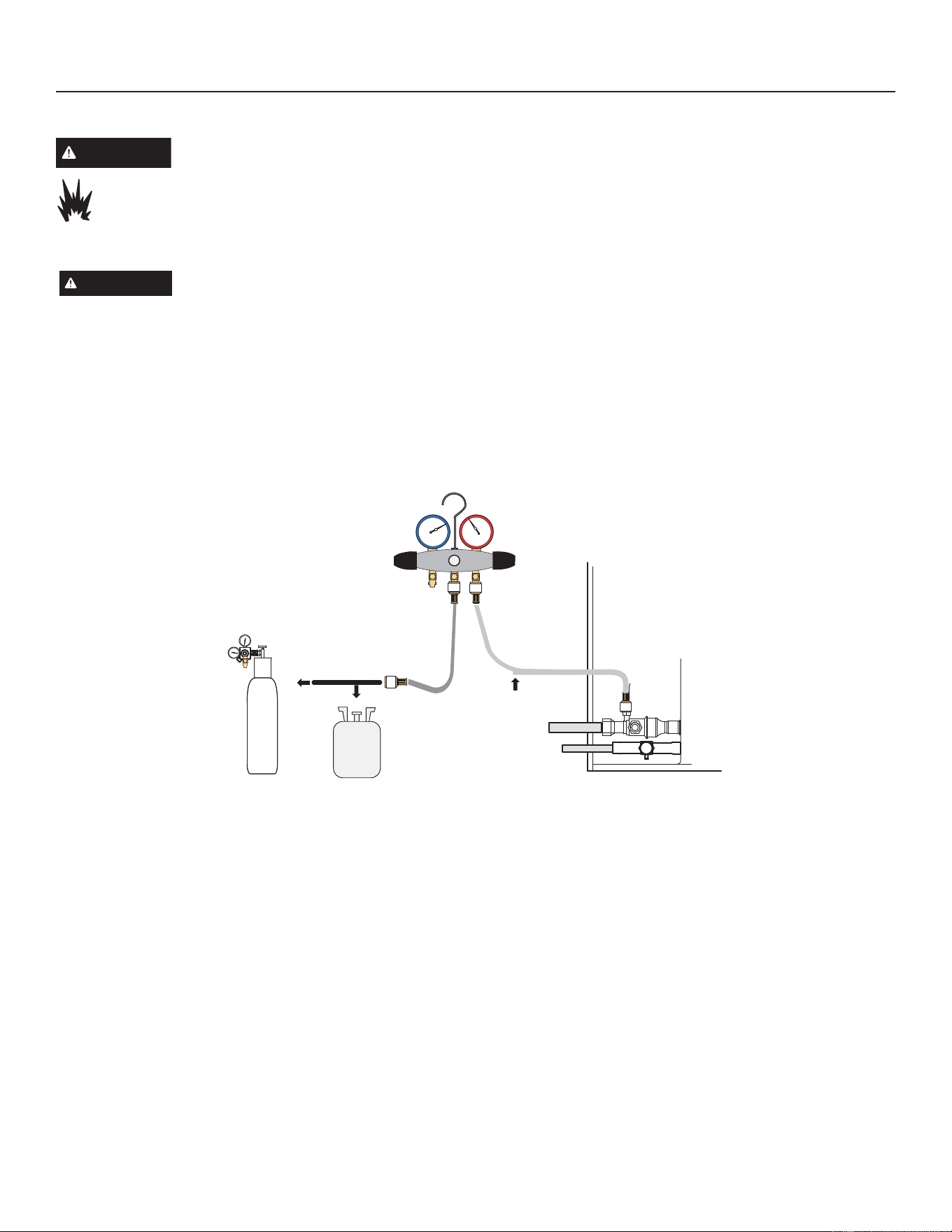
LINE SET AND INDOOR COIL
NOTE -1RUPDOO\WKHKLJKSUHVVXUHKRVHLVFRQQHFWHGWRWKHOLTXLGOLQHSRUW+RZHYHUFRQQHFWLQJLWWRWKHYDSRUSRUWEHWWHU
protects the manifold gauge set from high pressure damage.
1. CONNECT GAUGE SET
A. Connect an R-454B manifold gauge set high pressure hose to the vapor valve service port.
%:LWKERWKPDQLIROGYDOYHVFORVHGFRQQHFWWKHF\OLQGHURI5%UHIULJHUDQWWRWKHFHQWHUSRUWRIWKHPDQLIROGJDXJHVHW
NOTE -/DWHULQWKHSURFHGXUHWKH5%FRQWDLQHUZLOOEHUHSODFHGE\WKHQLWURJHQFRQWDLQHU
A
B
Low
High
Manifold Gauge Set
Outdoor Unit
To Vapor
Service Valve
R454B
Nitrogen
2. TEST FOR LEAKS
$IWHUWKHOLQHVHWKDVEHHQFRQQHFWHGWRWKHLQGRRUDQGRXWGRRUXQLWVFKHFNWKHOLQHVHWFRQQHFWLRQVDQGLQGRRUXQLWIRU
leaks. Use the following procedure to test for leaks:
$:LWKERWKPDQLIROGYDOYHVFORVHGFRQQHFWWKHF\OLQGHURI5%UHIULJHUDQWWRWKHFHQWHUSRUWRIWKHPDQLIROGJDXJHVHW
Open the valve on the R-454B cylinder (vapor only).
B. Open the high pressure side of the manifold to allow R-454B into the line set and indoor unit. Weigh in a trace amount
of R-454B. [A trace amount is a maximum of two ounces (57g) refrigerant or three pounds (31kpa) pressure]. Close the
valve on the R-454B cylinder and the valve on the high pressure side of the manifold gauge set. Disconnect the R-454B
cylinder.
C. Connect a cylinder of dry nitrogen with a pressure regulating valve to the center port of the manifold gauge set.
D. Adjust dry nitrogen pressure to 160psig (1103kpa). Open the valve on the high side of the manifold gauge set in order to
pressurize the line set and the indoor unit.
($IWHUDIHZPLQXWHVRSHQRQHRIWKHVHUYLFHYDOYHSRUWVDQGYHULI\WKDWWKHUHIULJHUDQWDGGHGWRWKHV\VWHPHDUOLHULV
PHDVXUDEOHZLWKDOHDNGHWHFWRU2QFHOHDNGHWHFWRULVFRQ¿UPHGRSHUDWLRQDOOHDNFKHFNWKHHQWLUHV\VWHP¿HOGMRLQWV
and line set included) to a sensitivity of 5 grams per year of refrigerant.
)$IWHUOHDNWHVWLQJGLVFRQQHFWJDXJHVIURPVHUYLFHSRUWV
Figure 11. System Leak Test
26
31-5000950 Rev. 0
Service Information
Evacuating Line Set and Indoor Coil
1. CONNECT GAUGE SET
NOTE - Remove cores from service valves (if not already done).
A. Connect low side of manifold gauge set with 1/4 SAE in-line tee to vapor line service valve
B. Connect high side of manifold gauge set to liquid R454B line service valve
C. Connect micron gauge available connector on the 1/4 SAE in-line tee.
D. Connect the vacuum pump (with vacuum gauge) to the center port of the manifold gauge set. The center port line will
be used later for both the R454B and nitrogen containers.
500
HIGH
LOW
A
B
C
D
.
Nitrogen
R454B
Vacuum Pump
Outdoor
Unit
A34000 1/4 SAE TEE
with Swivel Coupler
Micron
Gauge
To Vapor
Service Valve
Manifold
Gauge Set
To Liquid Line
Service Valve
Figure 12. Evacuating the System
27
31-5000950 Rev. 0
Service Information
Evacuating Line Set and Indoor Coil (cont)
2. EVACUATE THE SYSTEM
A. Open both manifold valves and start the vacuum pump.
%(YDFXDWHWKHOLQHVHWDQGLQGRRUXQLWWRDQDEVROXWHSUHVVXUHRIPLFURQVLQFKHVRIPHUFXU\
NOTE'XULQJWKHHDUO\VWDJHVRIHYDFXDWLRQLWLVGHVLUDEOHWRFORVHWKHPDQLIROGJDXJHYDOYHDWOHDVWRQFH$UDSLGULVH
LQSUHVVXUHLQGLFDWHVDUHODWLYHO\ODUJHOHDN,IWKLVRFFXUVrepeat the leak testing procedure.
NOTE - The term Absolute PressurePHDQVWKHWRWDODFWXDOSUHVVXUHZLWKLQDJLYHQYROXPHRUV\VWHPDERYHWKH
absolute zero of pressure. Absolute pressure in a vacuum is equal to atmospheric pressure minus vacuum pressure.
&:KHQWKHDEVROXWHSUHVVXUHUHDFKHVPLFURQVLQFKHVRIPHUFXU\SHUIRUPWKHIROORZLQJ
• Close manifold gauge valves
• Close valve on vacuum pump
7XUQRႇYDFXXPSXPS
• Disconnect manifold gauge center port hose from vacuum pump
• Attach manifold center port hose to a dry nitrogen cylinder with pressure regulator set to 160 psig (1103 kPa) and
purge the hose.
• Open manifold gauge valves to break the vacuum in the line set and indoor unit.
• Close manifold gauge valves.
'6KXWRႇWKHGU\QLWURJHQF\OLQGHUDQGUHPRYHWKHPDQLIROGJDXJHKRVHIURPWKHF\OLQGHU2SHQWKHPDQLIROGJDXJHYDOYHV
to release the dry nitrogen from the line set and indoor unit.
(5HFRQQHFWWKHPDQLIROGJDXJHWRWKHYDFXXPSXPSWXUQWKHSXPSRQDQGFRQWLQXHWRHYDFXDWHWKHOLQHVHWDQG
indoor unit until the absolute pressure does not rise above 500 microns (29.9 inches of mercury) within a 20-minute
SHULRGDIWHUVKXWWLQJRႇWKHYDFXXPSXPSDQGFORVLQJWKHPDQLIROGJDXJHYDOYHV
):KHQWKHDEVROXWHSUHVVXUHUHTXLUHPHQWDERYHKDVEHHQPHWGLVFRQQHFWWKHPDQLIROGKRVHIURPWKHYDFXXPSXPS
and connect it to an upright cylinder of R-454B refrigerant. Open the manifold gauge valve 1 to 2 psig in order to
release the vacuum in the line set and indoor unit.
G. Perform the following:
• Close manifold gauge valves.
6KXWRႇ5%F\OLQGHU
• Reinstall service valve cores by removing manifold hose from service valve. Quickly install cores with core tool while
maintaining a positive system pressure.
5HSODFHVWHPFDSVDQGVHFXUH¿QJHUWLJKWWKHQWLJKWHQDQDGGLWLRQDORQHVL[WKRI a
turn as illustrated.
WARNING
Possible equipment damage.
Avoid deep vacuum operation. Do not use compressors to evacuate a system. Extremely
low vacuum can cause internal arcing and compressor failure. Damage caused by deep
vacuum operation will void warranty.
IMPORTANT
Use a thermocouple or thermistor electronic vacuum gauge that is calibrated in microns. Use an
instrument capable of accurately measuring down to 50 microns.
(YDFXDWLQJWKHV\VWHPRIQRQFRQGHQVDEOHVLVFULWLFDOIRUSURSHURSHUDWLRQRIWKHXQLW1RQFRQGHQVDEOHVDUHGH¿QHGDV
any gas that will not condense under temperatures and pressures present during operation of an air conditioning system.
Non-condensables and water suction combine with refrigerant to produce substances that corrode copper piping and
compressor parts.
1/6 TURN
28
31-5000950 Rev. 0
Service Information
ELECTRICAL
Circuit Sizing and Wire Routing
,QWKH86$ZLULQJPXVWFRQIRUPZLWKFXUUHQWORFDOFRGHV
DQGWKHFXUUHQW1DWLRQDO(OHFWULF&RGH1(&,Q&DQDGD
wiring must conform with current local codes and the
current Canadian Electrical Code (CEC).
Refer to the furnace or air handler installation instructions
for additional wiring application diagrams and refer to unit
nameplate for minimum circuit ampacity and maximum
overcurrent protection size.
24VAC Transformer
Use the transformer provided with the furnace or air
handler for low-voltage control power (24VAC - 40 VA
minimum).
Thermostat Control and Low Voltage Control
Wiring
NS19H Thermostat Control Options
The NS19H variable capacity unit may be installed using
a conventional 24VAC non-communicating two-stage heat
pump thermostat.
NOTE – The conventional 24VAC non-communicating
thermostat must have a compressor minimum on time of
three minutes to prevent compressor short cycling. The
/HQQR[0&RPIRUW6HQVH&RPIRUW6HQVHDQG
many other commercially available electronic thermostats
provide this feature.
The NS19H unit will provide full variable capacity
operation when installed with a conventional 24VAC
non-communicating two stage heat pump or single-stage
heat pump thermostat. The NS19H outdoor control has
advanced control algorithms using the NS19H suction
pressure sensor to provide true variable capacity operation
LQWKHFRROLQJPRGH,QWKHKHDWSXPSKHDWLQJPRGH
the advanced control algorithms uses the NS19H liquid
pressure sensor to provide true variable capacity operation.
When utilizing a two-stage conventional 24VAC non-
FRPPXQLFDWLQJKHDWSXPSWKHUPRVWDWVL[ZLUHVDUH
UHTXLUHGWRFRQWUROWKHRXWGRRUXQLW5&<<2
and W). Refer to the NS19H¿HOGZLULQJGLDJUDPIRUD
conventional 24VAC non-communicating 2-stage heat
pump thermostat.
NS19H Low Voltage Control Wiring Connections
The NS19H variable capacity units are provided with (2)
RAST 6-Pin connections in the installation instruction bag
IRUFRQQHFWLQJWKH¿HOGORZYROWDJHFRQWUROZLULQJWRWKH
NS19H harnesses in the low voltage control make-up box.
One RAST 6-pin connector is labeled with terminals 767
')5,,DQG&7KHVHFRQG5$67SLQFRQQHFWRU is
ODEHOHGZLWKWHUPLQDOV'62<</DQG:
WARNING
• Electric Shock Hazard. Can cause injury or death. Unit
must be properly grounded in accordance with national
and local codes.
• Line voltage is present at all components when unit is
not in operation on units with single-pole contactors.
Disconnect all remote electric power supplies before
opening access panel. Unit may have multiple power
supplies.
• Fire Hazard. Use of aluminum wire with this
SURGXFWPD\UHVXOWLQD¿UHFDXVLQJSURSHUW\
GDPDJHVHYHUHLQMXU\RUGHDWK8VHFRSSHUZLUH
only with this product.
• Failure to use properly sized wiring and circuit breaker
may result in property damage. Size wiring and circuit
EUHDNHUVSHU3URGXFW6SHFL¿FDWLRQVEXOOHWLQ(+%DQG
unit rating plate.
29
31-5000950 Rev. 0
Service Information
WARNING
• Failure to use properly sized wiring and circuit breaker may result in property damage. Size wiring and circuit breaker(s)
SHU3URGXFW6SHFL¿FDWLRQVEXOOHWLQ(+%DQGXQLWUDWLQJSODWH
Thermostat Control Options
Thermostat Type Indoor Unit Type Qty. of Wires
Terminal Strip
Connections
Unit Operation
Field Wiring
Diagram
Conventional
24VAC 2-Stage
Heat Pump
Thermostat (non-
communicating)
Any Furnace or
Air Handler (non-
communicating or
communicating)
6 5&<<2:
Full Variable Capacity Operation Controlled
by NS19H Unitary Control Using Suction
Pressure in Cooling Mode and Liquid
Pressure in Heating Mode
Figure 16
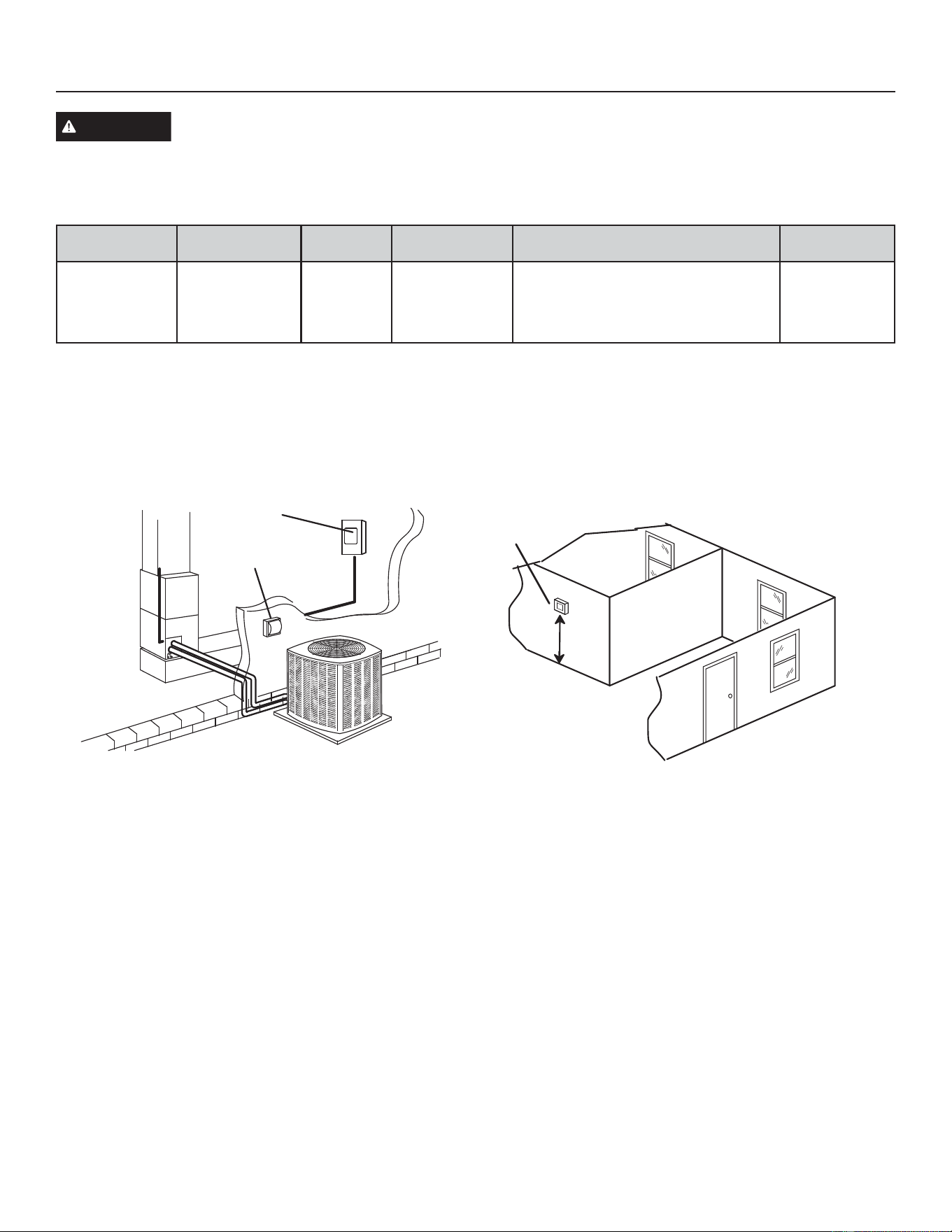
1. SIZE CIRCUIT AND INSTALL SERVICE DISCONNECT
SWITCH
5HIHUWRWKHXQLWQDPHSODWHIRUPLQLPXPFLUFXLWDPSDFLW\
and maximum fuse or circuit breaker (HACR per NEC).
Install power wiring and properly sized disconnect switch.
Main Fuse Box/
Breaker Panel
Service
Disconnect
Switch
NOTE - Units are approved for use only with copper
conductors. Ground unit at disconnect switch or to an earth
ground.
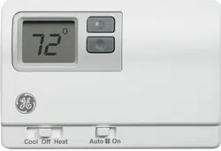
2. INSTALL THERMOSTAT
Install room thermostat (ordered separately) on an inside
wall approximately in the center of the conditioned area
DQGIHHWPIURPWKHÀRRU,WVKRXOGQRWEHLQVWDOOHG
RQDQRXWVLGHZDOORUZKHUHLWFDQEHDႇHFWHGE\VXQOLJKWRU
drafts.
Thermostat
5 ft
(1.5m)
NOTE9$&&ODVV,,FLUFXLWFRQQHFWLRQVDUHPDGHLQWKH
control panel.
30
31-5000950 Rev. 0
Service Information
ELECTRICAL
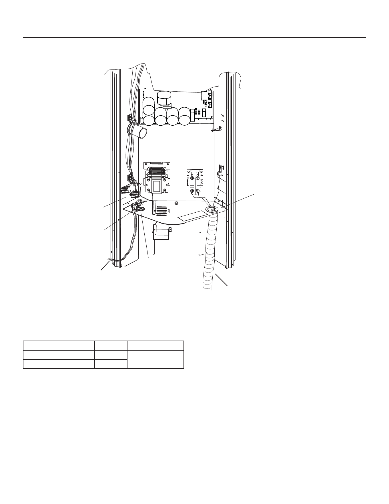
Connect conduit to cutout and
route high voltage wiring.
Use watertight conduit
for high voltage
Grommet and
Cable Tie
Route control wiring
through grommet and
secure with cable tie
Low Voltage
Make-Up Box
Connects to
(2) rast 6-Pin
connectors
3. ROUTE CONTROL WIRES
Conventional 24VAC Non-Communicating Thermostat
Wiring
Wire Run Length AWG# Insulation Type
Less than 100’ (30m) 18
Temperature Rating
&0LQLPXP
More than 100’ (30m) 16
4. ROUTE HIGH VOLTAGE AND GROUND WIRES
$Q\H[FHVVKLJKYROWDJH¿HOGZLULQJVKRXOGEHWULPPHGDQG
VHFXUHGDZD\IURPDQ\ORZYROWDJH¿HOGZLULQJ7RIDFLOLWDWH
DFRQGXLWDFXWRXWLVORFDWHGRQWKHERWWRPRIWKHFRQWURO
box. Connect conduit to the control box using a proper
FRQGXLW¿WWLQJ
Connect the 208/230 high voltage power supply from the
disconnect to the NS19H contactor as shown. Connect the
ground wire from the power supply to the unit ground lug
connection.
Figure 13. Typical Control Box
31
31-5000950 Rev. 0
Service Information
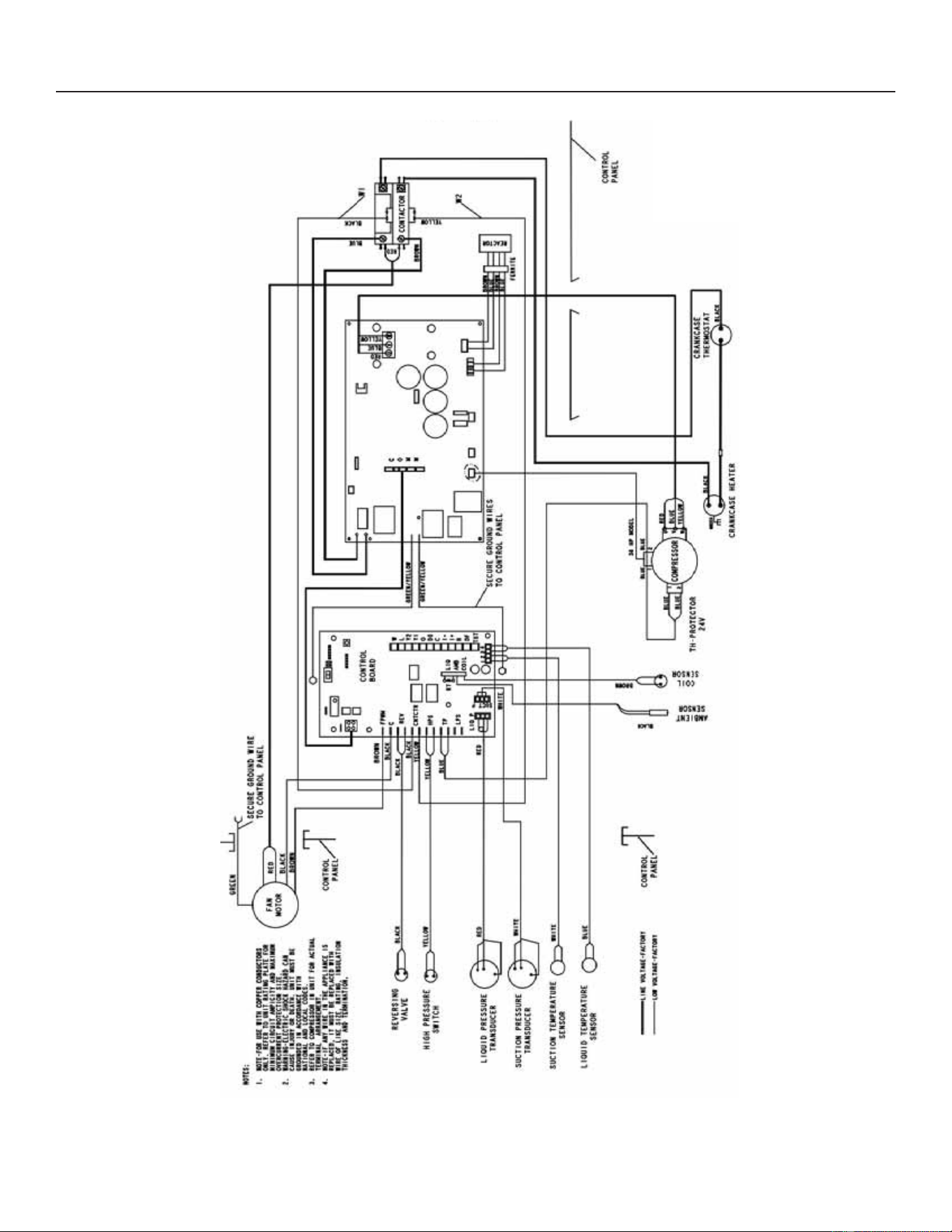
Figure 14. Typical Factory Wiring
32
31-5000950 Rev. 0
Service Information
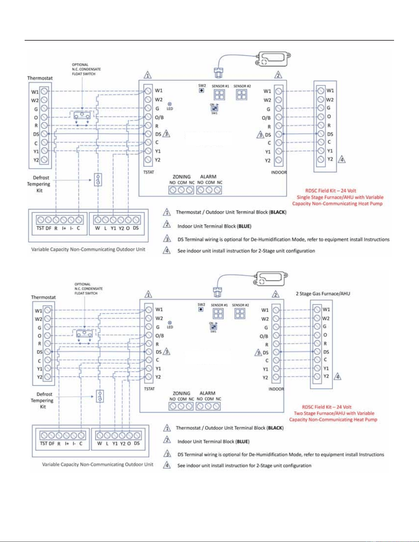
RDSC Field Kit - 24 Volt
Cat# (27A05)
RDSC Field Kit - 24 Volt
Cat# (27A05)
Figure 15. Single Stage and Two Stage Wiring
33
31-5000950 Rev. 0
Service Information
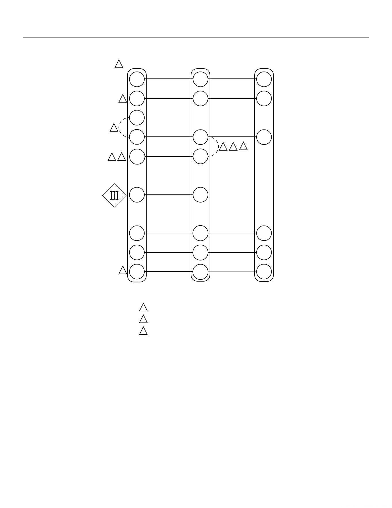
1
Refer to thermostat installation instructions
2
If applicable
3
Install jumper for single-stage operation on
electric heater kits 12.5KW and above
W1 / W2 are auxiliary heat
(supplemental to heat pump)
“E” is emergency heat (disables heat pump)
NOTES:
W2W2
R
R
R
C
C
C
W1
W/
W1
W1
Auxiliary Heat
(Heat Pump)
G
G
Indoor Blower Only
O
O
Heat Pump
Y2
Y2
Thermostat
CBK45
CBK47
RDS Control Board
Outdoor Unit
E
Y1
Compressor/1st
Stage
Y1
1
2
1
2
1
1
Auxiliary Heat
(Heat Pump)
Compressor/2nd
Stage
1
2
O
Y1
Y2
3
Figure 16. NS19H Variable Capacity Non-Communicating Heat Pump Installed with a GE NAM Series Air Handler
with Factory Installed RDS Control and Conventional 24V Thermostat
NAM
34
31-5000950 Rev. 0
Service Information
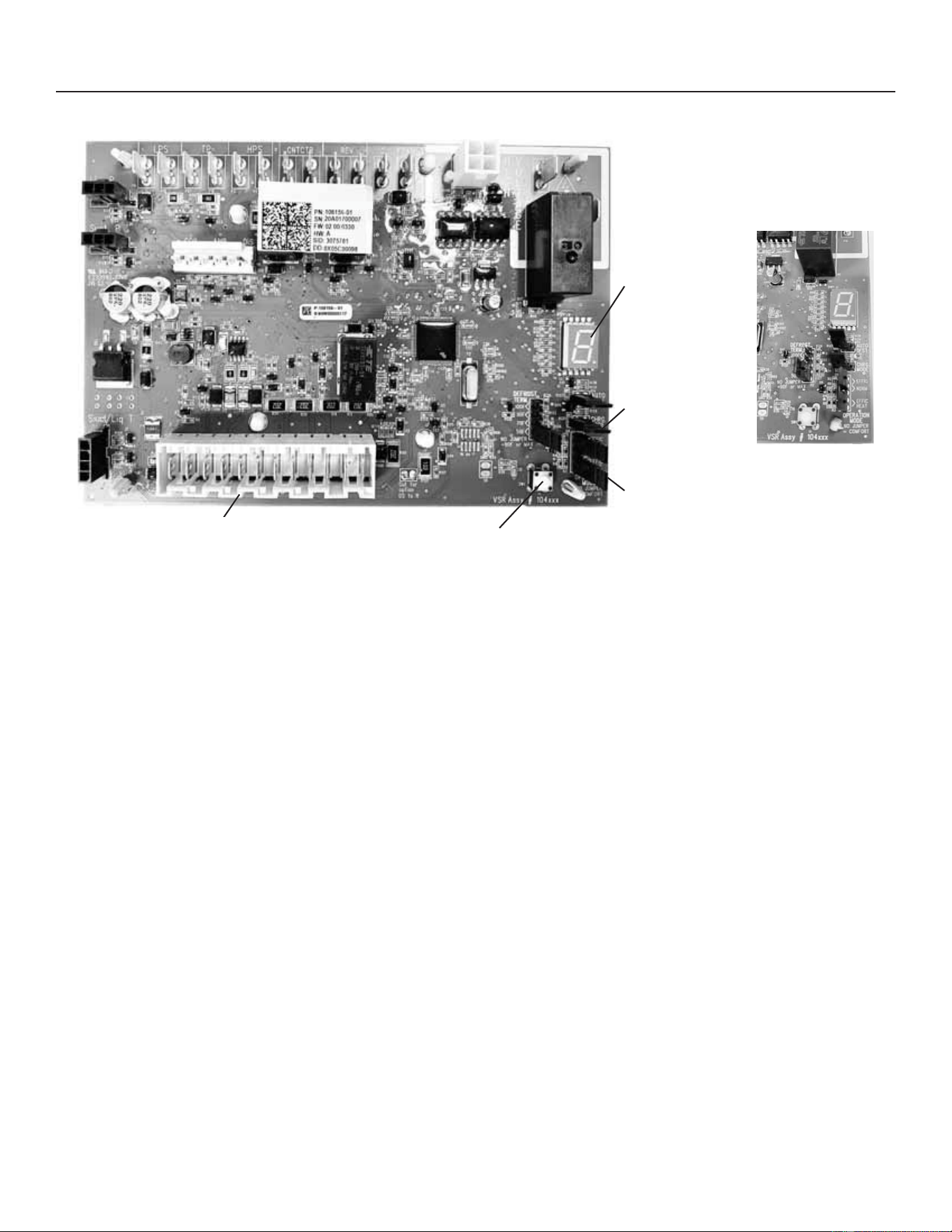
OUTDOOR UNITARY CONTROL - JUMPERS AND TERMINALS
7 Segment
Display
Charge Mode
-XPSHU
(CHRG MODE)
Operation
0RGH-XPSHU
Push Button
Raster Terminals for
Thermostat Wiring Connection
Charge Mode and
Operation Mode
-XPSHU'HWDLO
Outdoor Control 7 Segment Display and Push
Button
Information concerning the outdoor control 7-segment
display and push button operations are available on the
unit access panel.
Alarms
Alarm information is provided on the unit access panel.
Charge Mode Jumper
To initiate the NS19H&KDUJH0RGHIXQFWLRQLQVWDOOWKH
jumper across the two Charge Mode Pins (CHRG MODE)
on the outdoor control. The Charge Mode can be used
ZKHQFKDUJLQJWKHV\VWHPZLWKUHIULJHUDQWFKHFNLQJ
WKHUHIULJHUDQWFKDUJHSXPSLQJGRZQWKHV\VWHPDQG
performing other service procedures that requires outdoor
unit operation at 100% capacity.
NS19H Charge Mode Operation with a Conventional
24VAC Non-Communicating Heat Pump Thermostat
On applications with a conventional 24VAC non-
FRPPXQLFDWLQJWKHUPRVWDWWKHFKDUJHPRGHMXPSHUPXVW
be installed on the Charge Mode Pins after providing a Y1
compressor demand to the NS19H to initiate the Charge
0RGH:KHQXVLQJWKH&KDUJH0RGHLQWKHFRROLQJPRGH
the “O” must also be provided with a 24V signal to place
the reversing valve in the cool position. In the heating mode
only a Y1 compressor demand is required along with the
blower demand for the full cooling air volume. A cooling
blower demand must also be provided to initiate blower
operation on the cooling speed on the indoor unit. The
compressor and outdoor fan motor will operate at 100%
FDSDFLW\7RH[LWWKHFKDUJLQJPRGHUHPRYHWKH&KDUJH
0RGH-XPSHUDQGUHPRYHWKH<&RROLQJGHPDQGDQG
indoor blower demand. The Charge Mode has a maximum
time of 60 minutes and will automatically exit the charge
mode after 60 minutes is the charge mode jumper is left in
place.
Cooling Operation Mode Jumper
7KH&RROLQJ2SHUDWLRQ0RGH-XPSHULVRQO\XVHGRQ
applications installed with a conventional 24VAC non-
communicating heat pump thermostat. In applications
with a conventional 24VAC non-communicating heat
pump WKHUPRVWDWWKHFRPSUHVVRUFDSDFLW\LVFRQWUROOHGWR
maintain the target suction pressure setpoint. The Cooling
2SHUDWLRQ0RGH-XPSHUKDVWKUHHVHOHFWDEOHFRROLQJ
PRGHV7KHWKUHHPRGHVDUH(ႈFLHQF\-XPSHULQVWDOOHG
RQ3LQVDQG1RUPDO0RGH-XPSHULQVWDOOHG on Pins 2
DQGDQG&RPIRUW0RGH-XPSHU5HPRYHG The factory
GHIDXOWSRVLWLRQLVWKH(ႈFLHQF\0RGH

35
31-5000950 Rev. 0
Service Information
7KH(ႈFLHQF\PRGHKDVDYDULDEOHVXFWLRQSUHVVXUH
set-point that will vary with the outdoor temperature; as
the outdoor temperature increases the suction pressure
set-point will decrease. When the Cooling Operation
Mode jumper is installed in the “Normal Mode” the suction
pressure set-point is 135 psig. When the Cooling Operation
Mode jumper is installed in the “Comfort Mode” the suction
pressure set-point is 125 psig.
Heating Operation Mode Jumper
7KH+HDWLQJ2SHUDWLRQ0RGH-XPSHULVRQO\XVHGRQ
applications installed with a conventional 24VAC non-
communicating heat pump thermostat. In applications
with a conventional 24VAC non-communicating heat
SXPSWKHUPRVWDW the compressor capacity is controlled to
maintain the target liquid pressure set-point. The Heating
Operation 0RGH-XPSHUKDVWZRVHOHFWDEOHKHDWLQJPRGHV
The two PRGHVDUH(ႈFLHQF\-XPSHULQVWDOOHGRQ3LQV
and 2) DQG&RPIRUW0RGH-XPSHU5HPRYHG7KHIDFWRU\
default SRVLWLRQLVWKH(ႈFLHQF\0RGH7KH(ႈFLHQF\
mode has a variable liquid pressure set-point that will vary
with the outdoor temperature; as the outdoor temperature
GHFUHDVHV the liquid pressure set-point will increase. When
the Operation Mode jumper is installed in the “Comfort
Mode” the liquid pressure set-point is 425 psig.
Unit Operation
NS19H Unit Operation with a Conventional 24VAC
Non-Communicating 2-Stage Heat Pump Thermostat –
Cooling Mode
When the NS19H unit is installed with a conventional
9$&QRQFRPPXQLFDWLQJVWDJHKHDWSXPSWKHUPRVWDW
the O terminal on the thermostat will energize the unit
reversing valve to place the unit in the cooling mode. A Y1
¿UVWVWDJHFRROLQJGHPDQGZLOOLQLWLDWHFRROLQJRSHUDWLRQ
and ¿UVWVWDJHLQGRRUEORZHURSHUDWLRQ7KHFRPSUHVVRU
will be controlled in the variable capacity mode by varying
the compressor capacity to obtain the target suction
pressure set point. The Y2 second stage cooling demand
will initiate second stage blower operation. Increased
air volume will increase the load on the indoor coil and
increase the suction pressure. The NS19H compressor
capacity will continue to be controlled based upon the
suction pressure. The unit capacity will be controlled in the
variable capacity mode throughout the range of capacity
from minimum capacity to maximum capacity. If the Y2
demand remains DIWHUPLQXWHVWKHNS19H control will
begin to ramp up the compressor capacity until maximum
capacity is achieved. The NS19HXQLWZLOOF\FOHRႇRQFH
the thermostat GHPDQGLVVDWLV¿HG
NS19H Unit Operation with a Conventional 24VAC
Non-Communicating 2-Stage Heat Pump Thermostat -
Heating Mode
When the NS19H unit is installed with a conventional
9$&QRQFRPPXQLFDWLQJVWDJHKHDWSXPSWKHUPRVWDW
O terminal is not powered during the heating mode and
the reversing valve is de-energized placing hte unit in
WKHKHDWLQJPRGH$<¿UVWVWDJHFRPSUHVVRUGHPDQG
will LQLWLDWHFRPSUHVVRURSHUDWLRQDQG¿UVWVWDJHLQGRRU
blower operation. The compressor will be controlled in
the variable capacity mode by varying the compressor
capacity to obtain the target liquid pressure set point. The
Y2 second stage compressor demand will initiate second
stage blower operation. Increased air volume will increase
heat transfer on the indoor coil and decrease the liquid
pressure. if the liquid pressure drops below the target
VHWSRLQW the compressor capacity will be increased. The
NS19H compressor capacity will continue to be controlled
based upon the liquid pressure. The unit capacity will be
controlled in the variable capacity mode throughout the
range of capacity from minimum capacity to maximum
capacity. ,IWKH<GHPDQGUHPDLQVDIWHUPLQXWHV
the NS19H control will begin to ramp up the compressor
capacity until maximum capacity is achieved. The NS19H
unit will cycle RႇRQFHWKHWKHUPRVWDWGHPDQGLVVDWLV¿HG
Defrost Function
The outdoor unit control uses a time dependent frost
accumulation duration demand defrost control algorithm
to provide a demand defrost when the system falls below
optimum levels. The demand defrost control algorithm
is reactive based upon the previous heat pump run time
between defrost cycles (frost accumulation time) and
the time spend in defrost (defrost time). The outdoor
unit control PRQLWRUVDPELHQWWHPSHUDWXUHRXWGRRU
coil temperature along with the compressor run time in
heating mode and defrost cycle time. The outdoor unit
control monitors compressor run time in the heating mode
when the out-door FRLOWHPSHUDWXUHLVEHORZ)DQG
accumulates the frost accumulation time. Once the frost
accumulation time is met the unit control will initiate a
defrost cycle. The unit will run in the defrost mode until
the coil temperature reaches the defrost termination
temperature set-point. The maximum length of defrost cycle
is 14 minutes and the defrost cycle will automatically be
terminated if the defrost cycle exceeds 14 minutes.
Two consecutive low pressure switch trips while operating
in the heat pump heating mode will initiate a defrost cycle
to defrost that may occur during a weather-related event
such as freezing rain.
Frost Accumulation Time
The frost accumulation time is the amount of time the
heat pump runs in the heating mode when the outdoor
coil WHPSHUDWXUHLVEHORZ)7KHLQLWLDOWDUJHWIURVW
accumulation WLPHLVPLQXWHVEXWWKHFRQWUROZLOODGMXVW
the frost accumulation time higher or lower based upon the
previous defrost cycle time history. If the defrost cycle time
is short (80% or less of the defrost cycle time) the defrost
accumulation time will be increased by 30 minutes.
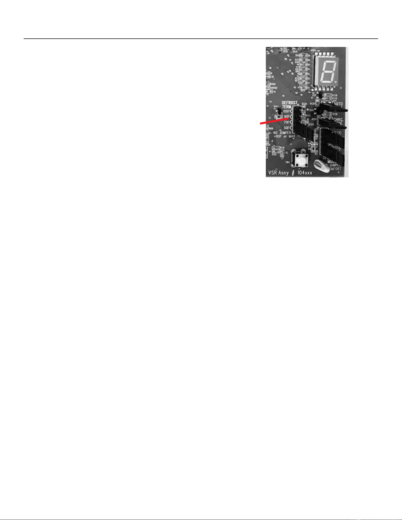
36
31-5000950 Rev. 0
Service Information
If the defrost cycle time is long (120% or more of the target
defrost cycle time) the defrost accumulation time will be
decreased by 30 minutes. If the defrost accumulation time
LVVLJQL¿FDQWO\ORQJHURUPRUHRIWKHWDUJHWGHIURVW
cycle time) or if the defrost terminates at the 14-minute
PD[LPXPWLPHWKHIURVWDFFXPXODWLRQWLPHLVVHWWR
minutes. No change to frost accumulation time is made if
the frost accumulation time is close to the target defrost
cycle time (between 80% and 120% of the target defrost
cycle time).
Low Ambient Defrost
:KHQRXWGRRUWHPSHUDWXUHLVOHVVWKDQ)WKH)URVW
Accumulation Time will be set to 360 minutes. When
WKHRXWGRRUWHPSHUDWXUHLVH[WUHPHO\FROGWKHUHLVOHVV
PRLVWXUHLQWKHDLUZKLFKUHGXFHVWKHGHIURVWIUHTXHQF\
requirements. Setting the frost accumulation time to 360
minutes will reduce the defrost cycle frequency which
will LQFUHDVHWKHRYHUDOOV\VWHPHႈFLHQF\DQGPLQLPL]H
operation costs. The Low Ambient Defrost had adjustable
SDUDPHWHUV allowing the technician to make adjustments
for the special application and climate.
Defrost Cycle Time
The defrost cycle time is the amount of time the unit
operates in the defrost mode from the point the defrost
cycle ZDVLQLWLDWHGXQWLOWKHFRLOWHPSHUDWXUHUHDFKHV)
regardless of defrost termination temperature set-point. The
demand defrost control target defrost cycle time is unique
for each NS19H heat pump model. The target defrost cycle
time of NS19H-036 is 125s and NS19H-060 is 135s.
NOTE - The outdoor unit control accurately measures the
performance of the system as frost accumulates on the
outdoor coil. This typically translates into longer running
time between defrost cycles as more frost accumulates on
the outdoor coil before the outdoor control initiates defrost
cycles.
NOTE – Colder climates may require a higher defrost
termination temperature setting to ensure the outdoor coil
is cleared of frost during defrost. If the outdoor coil is not
DGHTXDWHO\FOHDUHGRIIURVWWKHKHDWSXPSPD\H[SHULHQFH
reduced heating performance or damage to the outdoor coil
from the buildup of ice on the coil.
Defrost
Termination
-XPSHU
Figure 17. Defrost Termination Jumper
NS19H Installations with a Conventional 24VAC Heat
Pump Thermostat
The unitary control has a defrost termination jumper to set
the defrost termination temperature using the jumper on
the unitary control. The defrost termination jumper setting
VHOHFWLRQVDUHDQG)7KHIDFWRU\GHIDXOW
setting is 50ºF (10ºC).
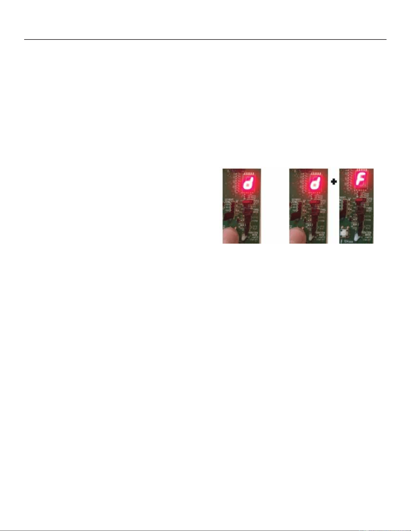
37
31-5000950 Rev. 0
Service Information
Defrost Test
The NS19H defrost cycle can be tested for defrost
diagnostic purposes or during service procedures to initiate
a defrost cycle to clear the outdoor coil of frost or ice. The
NS19H may be placed into a forced defrost mode by using
the Outdoor Unitary Control push button.
To Initiate a Forced Defrost Cycle Using the Unitary
Control Push Button:
1 - While the NS19HLVRSHUDWLQJLQWKHKHDWLQJPRGH
press bush button until solid “-” is displayed to enter
Field Test Mode and then release the button.
2 - Press and hold the button until “d” is displayed for
IRUFHGGHIURVWF\FOHWKHQUHOHDVHWKHEXWWRQ3UHVV the
EXWWRQDJDLQZKLOHWKHGLVSOD\LVÀDVKLQJ³G´WR select
the forced defrost mode.
3 - The NS19HZLOOHQWHUDIRUFHGGHIURVWF\FOHDQG³G´
“F” will be displayed on the 7-segment display.
4 - The 30-second Shift Delay will be observed. The
FRPSUHVVRUDQGRXWGRRUIDQZLOOF\FOHRႇ$IWHU a
VHFRQGGHOD\WKHUHYHUVLQJYDOYHZLOOEH energized
and will shift to the “cool” position. After a 26-second
GHOD\WKHFRPSUHVVRUZLOOUHVWDUWDQG will run at the
maximum cooling speed in the defrost cycle to defrost
the coil.
5 - Coil “c” and Ambient “A” temperature will be displayed
on the 7-segment display.
The Forced Defrost Cycle will end when any of the
following conditions are met:
• The defrost cycle will terminate upon reaching the defrost
termination temperature setting set on Unitary Control.
• Defrost cycle will terminate at the maximum allowable
defrost time of 14 minutes has been reached.
• The defrost cycle will terminate after 10 seconds if the
RXWGRRUDPELHQWWHPSHUDWXUHLV)RUJUHDWHUWRSUHYHQW
opening of the the high pressure switch.
• The unitary control push button is pressed to terminate
the forced defrost cycle test.
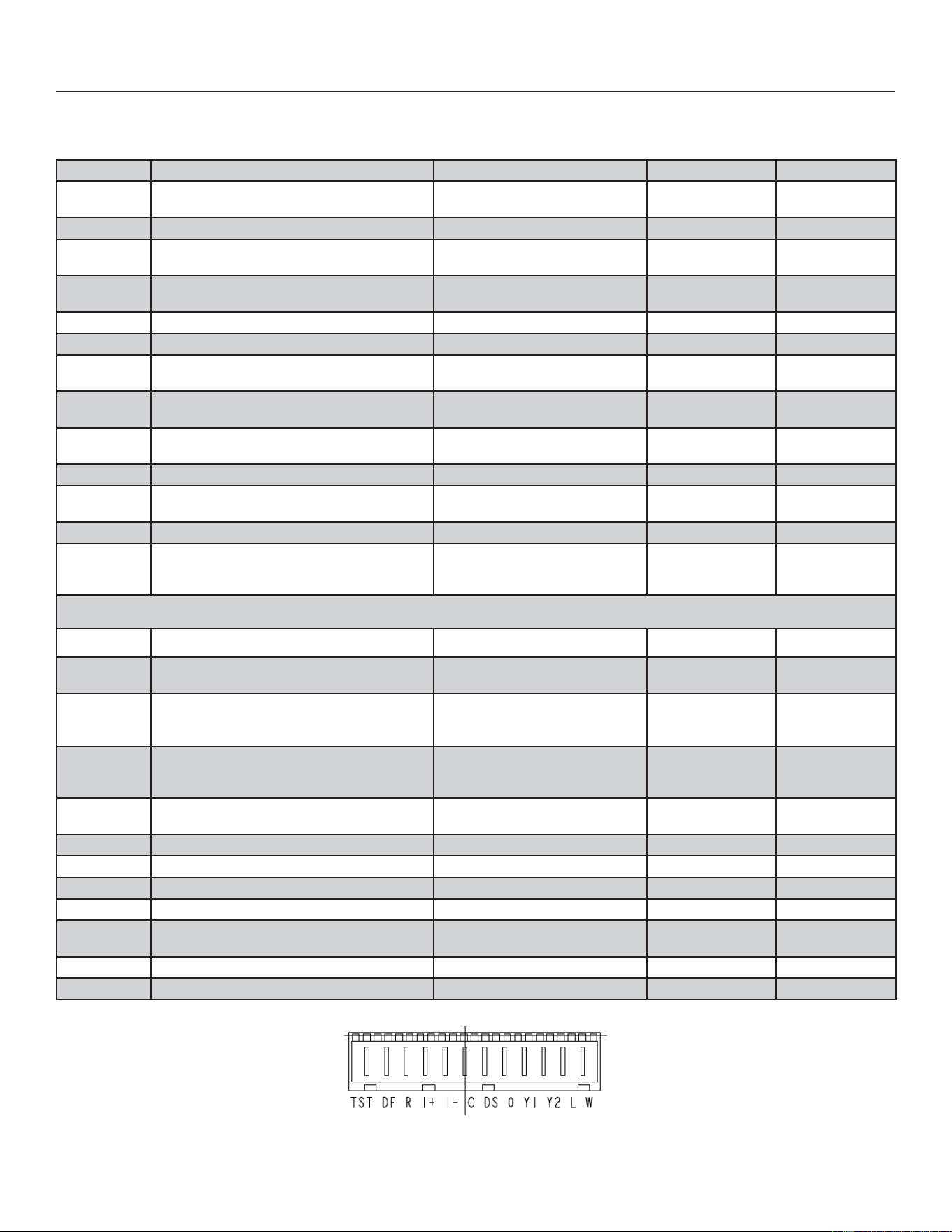
38
31-5000950 Rev. 0
Service Information
Table 6. Outdoor Control Terminal Designations and Input /Outputs
(see Figures 14 and 15 for terminal locations)
Designator Description Input Output Common
O
O Reversing Valve Input (24VAC conventional
Heat Pump Thermostats only)
24VAC
Switched 24VAC
nominal
N/A
REV Reversing valve output N/A 24VAC nominal 24VAC common
LPS
Not used on NS19H (Suction Pressure
Transducer emulates the LPS
N/A N/A N/A
LPS
Not used on NS19H (Suction Pressure
Transducer emulates the LPS
24VAC nominal N/A N/A
HPS High pressure switch N/A 24VAC nominal N/A
HPS High pressure switch sensing connection 24VAC nominal N/A N/A
TP
Top cap thermostat switch (in series with the
HPS)
N/A 24VAC nominal N/A
TP Top cap thermostat switch sensing connection 24VAC nominal N/A N/A
Cntctr
Control (inverter power) contactor switched
output (in series with the HPS and TC)
N/A
Switched 24VAC
nominal
N/A
Cntctr Contactor common N/A N/A 24VAC common
FPWM PWM fan output N/A
GXW\F\FOH
19-23 VDC peak
C PWM fan common connection N/A N/A Fan PWM common
P10 (PSC Fan
ފ4&
ފ4&WHUPLQDOV6ZLWFKHGRXWSXWIRU36&
outdoor fan control (not used on NS19H heat
pumps)
N/A
Switched 230VAC
Nominal
N/A
RAST Connector Terminal Designations
W 24VAC Output for defrost auxiliary heat output N/A 24VAC nominal N/A
L 24VAC input to initiate load shed
24VAC nominal from load shed N.O.
contacts (close to initiate load shed)
N/A N/A
Y2
Y2 second stage cooling input when a
conventional 24VAC non-communicating
thermostat is used.
24VAC nominal from thermostat N/A N/A
Y1
<¿UVWVWDJHFRROLQJLQSXWZKHQDFRQYHQWLRQDO
24VAC non-communicating thermostat is used
24VAC nominal from thermostat N/A N/A
O
O Reversing Valve Input (24VAC conventional
Heat Pump Thermostats only)
24VAC nominal from thermostat N/A N/A
DS 'HKXPLGL¿FDWLRQLQSXWQRWXVHG N/A N/A N/A
C 24VAC nominal power return N/A N/A 24VAC common
I- Low data line Data Data N/A
I+
High data line Data Data N/A
R 24VAC nominal power input
24VAC nominal board main power
input
N/A N/A
DF OEM test N/A N/A N/A
TST OEM test pin 24VAC nominal N/A N/A
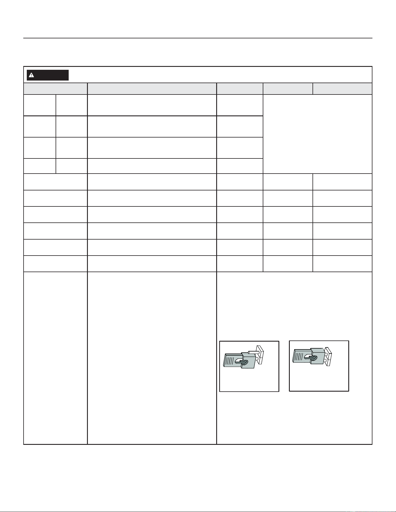
39
31-5000950 Rev. 0
Service Information
TABLE 6. Outdoor Control Terminal Designations and Input /Outputs
VHH¿JXUHVDQGIRUWHUPLQDOORFDWLRQV
WARNING
Electric Shock Hazard. Can cause injury or death. Unit must be grounded in accordance with national and local
codes. The 4 pins in P6 have the potential of transferring up to 250 volts to the unit cabinet ground.
Designator Description Input Output Common
P6 - Pin 1 Tx 7UDQVPLWGDWDWRLQYHUWHUFRQQHFWVWR5[RILQYHUWHU
Outdoor control
communication
transmit pin
– Pin 1 to Pin 2 should read 4.5 to 5.55 VDC
when not communicating
– Pin 3 to Pin 2 should read 4.5 to 5.55 VDC
when not communicating
– Pin 4 to Pin 2 should read 4.5 to 5.55 VDC
NOTE - Communication signals switch
RႇDQGRQUDSLGO\7KLVPD\FDXVHYROW
PHWHUUHDGLQJVWRÀXFWXDWH7KLVLVQRUPDO
Communication signals will switch between
this 5V and common (Pin 2).
P6 - Pin2
Inverter
Common
Inverter common
NOTE – This is a signal reference point and not an
earth ground.
Inverter common
P6 - Pin 3 Rx
Receive data from the inverter
Connects to Tx of inverter
Outdoor control
communication
receive pin
P6 - Pin 4 Inv 5V Inverter 5VDC volts
Inverter 5VDC
volts
DIS
Discharge Line temperature sensor - not used (10K
ohm resistor installed)
N/A N/A N/A
DIS
Discharge Line temperature sensor - not used (10K
ohm resistor installed)
N/A N/A N/A
AMB Outdoor ambient temperature sensor supply N/A N/A N/A
AMB Outdoor ambient temperature sensor return N/A N/A N/A
COIL
Outdoor coil temperature sensor - not used (10K ohm
resistor installed)
N/A N/A N/A
COIL
Outdoor coil temperature sensor - not used (10K ohm
resistor installed)
N/A N/A N/A
CHRG MODE
Conventional 24VAC heat pump thermostat -
Cooling mode
1. Provide a Y1 compressor demand and a O Reversing
Valve signal to the NS19H.
2. Install the Charge Mode jumper (after the Y1
demand)
3. A blower demand must be provided to the indoor unit
for 100% of the cooling air volume.
4. Remove the charge mode jumper to end the charge
mode
Conventional 24VAC Heat Pump Thermostat -
Heating Mode
1. Provide a Y1 compressor heating demand (without
an O demand)
2. Install the Charge Mode jumper (after the Y1
demand)
3. A blower demand must be provided to the indoor unit
for 100% of the heating air volume.
4. Remove the charge mode jumper to end the charge
mode.
NOTE - If the charge mode jumper is in the ON position
GXULQJSRZHUXSLWLVLJQRUHG
NOTE ,I WKH FKDUJH PRGH LV OHIW LQ SODFH LW ZLOO EH
ignored after 60 minutes.
CHRG
Charge Mode
Disabled
Charge Mode
Enabled
MODE
CHRG
MODE
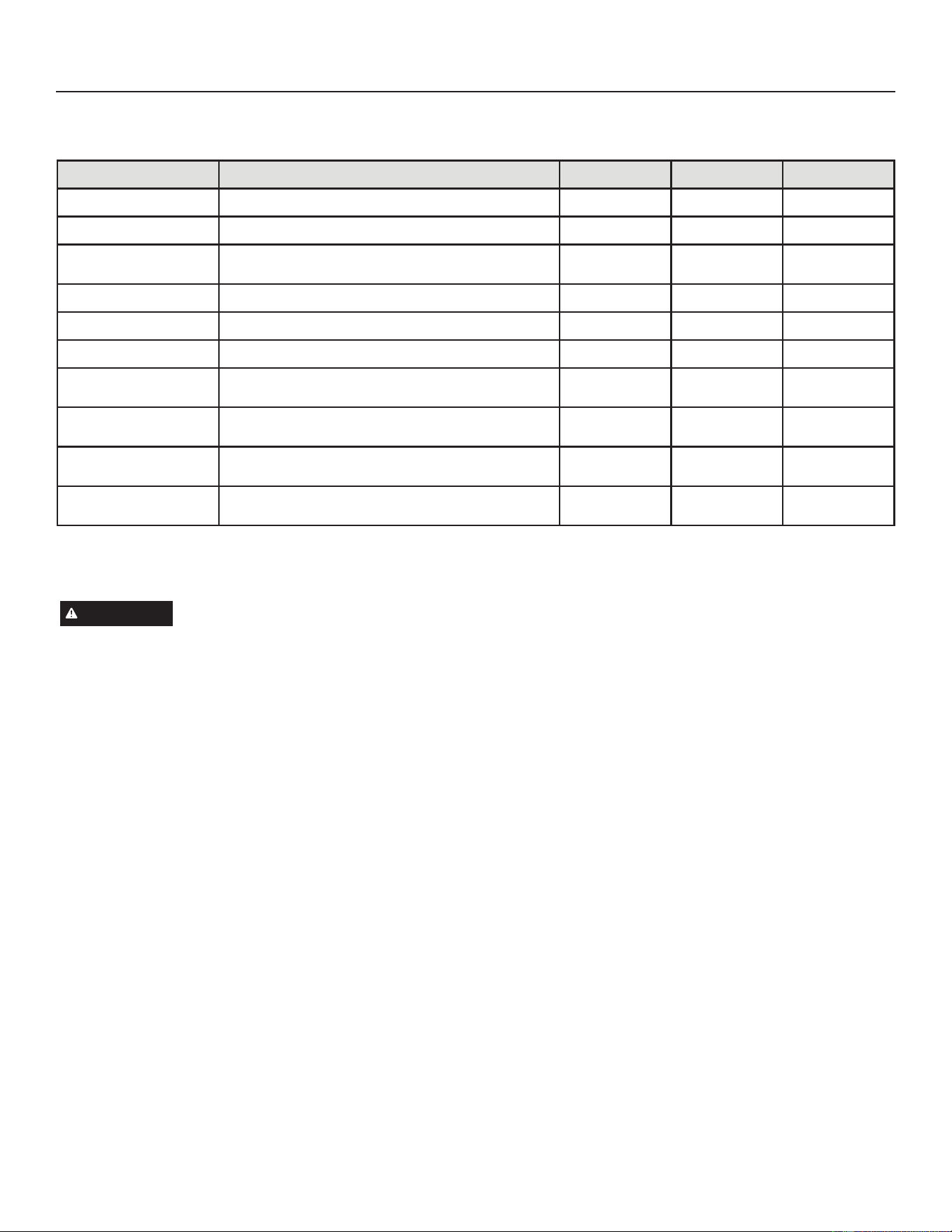
40
31-5000950 Rev. 0
Service Information
TABLE 6. Outdoor Control Terminal Designations and Input /Outputs
VHH¿JXUHVDQGIRUWHUPLQDOORFDWLRQV
Designator Description Input Output Common
Suction Pressure Out Pressure transducer Supply Voltage Pin 1 of 3 5 VDC
Suction Pressure In Pressure transducer output voltage Pin 2 of 3 0.5-4.5 VDC
Suction Pressure
GND
Pressure transducer GND Pin 3 of 3 VDC Com
Liquid Pressure Out Pressure transducer Supply Voltage Pin 1 of 3 5 VDC
Liquid Pressure In Pressure transducer Supply Voltage Pin 2 of 3 0.5-4.5 VDC
Liquid Pressure GND Pressure transducer GND Pin 3 of 3 VDC Com
SUCT1 Suction Line Temperature Sensor Supply - Pin 1 of 4
2.680k ohms to
327.3k ohms
SUCT2 Suction Line Temperature Sensor Supply - Pin 2 of 4
2.680k ohms to
327.3k ohms
LIQ1 Liquid Line Temperature Sensor Supply - Pin 3 of 4
2.680k ohms to
327.3k ohms
LIQ2 Liquid Line Temperature Sensor Supply - Pin 4 of 4
2.680k ohms to
327.3k ohms
Unit Start-Up
IMPORTANT
,IXQLWLVHTXLSSHGZLWKDFUDQNFDVHKHDWHULWVKRXOG
be energized 24 hours before unit start-up to prevent
compressor damage as a result of slugging.
1 - Rotate fan to check for binding.
,QVSHFWDOOIDFWRU\DQG¿HOGLQVWDOOHGZLULQJIRUORRVH
connections.
$IWHUHYDFXDWLRQLVFRPSOHWHRSHQERWKWKHOLTXLGDQG
vapor line service valves to release the refrigerant
charge contained in outdoor unit into the system.
4 - Replace the stem caps and tighten to the value listed in
Table 1.
5 - Check voltage supply at the disconnect switch. The
voltage must be within the range listed on the unit’s
QDPHSODWH,IQRWGRQRWVWDUWWKHHTXLSPHQWXQWLO\RX
have consulted with the power company and the voltage
condition has been corrected.
6 - Set the thermostat for a cooling demand. Turn on power
to the indoor unit and close the outdoor unit disconnect
switch to start the unit.
7 - Recheck voltage while the unit is running. Power must
be within range shown on the nameplate.
&KHFNV\VWHPIRUVXႈFLHQWUHIULJHUDQWE\XVLQJWKH
procedures listed in the System Refrigerant section on
Page 83.
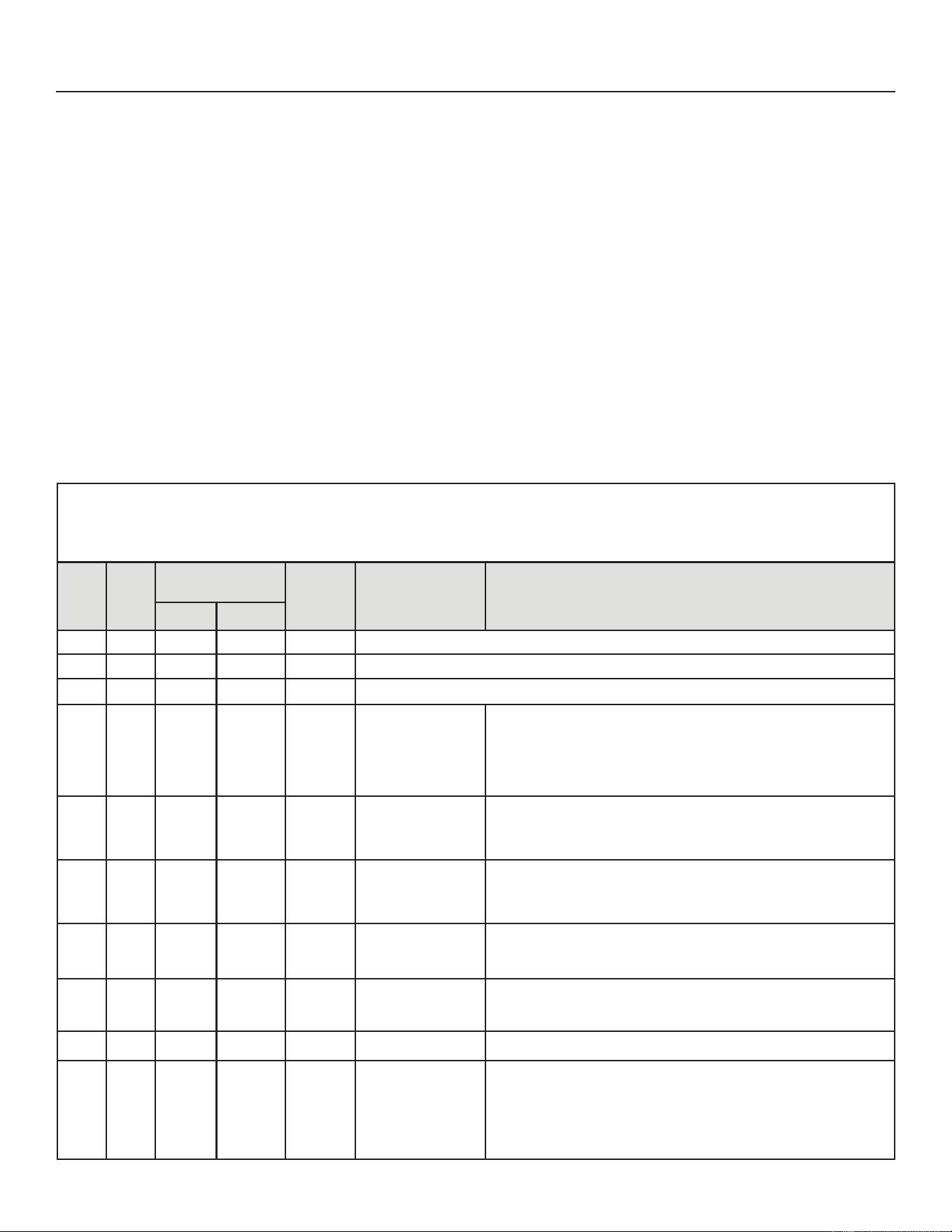
41
31-5000950 Rev. 0
Service Information
SYSTEM OPERATION AND SERVICE
7-Segment Alert and System Status Codes
Alert codes are displayed using the 7-segment display
located on the outdoor control.
NOTE - System fault and lockout codes take precedence
RYHUV\VWHPVWDWXVFRGHVFRROLQJKHDWLQJRSHUDWLQJ
SHUFHQWDJHVRUGHIURVWGHKXPLGL¿FDWLRQ
The 7-segment will display an abnormal condition (error
code) when detected in the system. A list of the codes are
shown in Table 7.
Resetting Alert Codes
Alert codes can be reset manually or automatically:
1 - Manual Reset
Manual reset can be achieved by one of the following
methods:
• Disconnecting R wire from the outdoor control R
terminal.
7XUQLQJWKHLQGRRUXQLWRႇDQGEDFNRQDJDLQ
$IWHUSRZHUXSDOOFXUUHQWO\GLVSOD\HGFRGHVDUHFOHDUHG
2 - Automatic Reset
$IWHUDQDOHUWLVGHWHFWHGWKHRXWGRRUFRQWUROFRQWLQXHV
to monitor the unit's system and compressor operations.
:KHQLIFRQGLWLRQVUHWXUQWRQRUPDOWKHDOHUWFRGHLV
WXUQHGRႇDXWRPDWLFDOO\
NOTE - Error codes can be recalled by following
information shown in the table on Page 50.
Table 7. Outdoor Control 7-Segment Display Alert Codes and Inverter LED Flash Codes
NOTE:6\VWHPIDXOWDQGORFNRXWFRGHVWDNHSUHFHGHQFHRYHUV\VWHPVWDWXVFRGHVFRROLQJKHDWLQJRSHUDWLQJSHUFHQWDJHVRUGHIURVW
GHKXPLGLILFDWLRQ2QO\WKHODWHVWDFWLYHIDXOWRUORFNRXWFRGHVDUHGLVSOD\HGLISUHVHQW,IQRIDXOWRUORFNRXWFRGHVDUHDFWLYHWKHQV\VWHPVWDWXV
codes are displayed.
Alert
Code
Inverter
Code
Inverter Flash Code
QXPEHURIÀDVKHV
Priority Alarm Description Possible Causes and Clearing Alarm
Red LED Green LED
N/A N/A ON OFF N/A 36 only: Indicates inverter is operating normally.
N/A N/A ON ON N/A 60 only: Indicates inverter is operating normally.
N/A N/A OFF OFF N/A Indicates inverter is NOT energized.
E105 N/A N/A N/A Moderate
The outdoor control has
lost communication with
either the thermostat or
indoor unit.
Equipment is unable to communicate. Indicates numerous message errors. In
most cases errors are related to electrical noise. Make sure high voltage power is
separated from RSBus. Check for miswired and/or loose connections between the
VWDWLQGRRUXQLWDQGRXWGRRUXQLW&KHFNIRUDKLJKYROWDJHVRXUFHRIQRLVHFORVH
to the system. Fault clears after communication is restored.
E120 N/A N/A N/A Moderate
There is a delay in the
outdoor unit responding
to the system.
7\SLFDOO\WKLVDODUPFRGHGRHVQRWFDXVHDQ\LVVXHVDQGFOHDUVRQLWVRZQ7KH
alarm/code is usually caused by a delay in the outdoor unit responding to the
thermostat. Check all wiring connections. Cleared after unresponsive device
responds to any inquiry.
E124 N/A N/A N/A Critical
The S40 thermostat
has lost communication
with the outdoor unit for
more than 3 minutes
Equipment lost communication with the thermostat. Check the wiring connections
DQGUHVLVWDQFHWKHQF\FOHWKHV\VWHPSRZHU7KLVDODUPVWRSVDOODVVRFLDWHG
HVAC operations and waits for a signal from the non-communicating unit. The
alarm / fault clears after communication is re-established.
E125 N/A N/A N/A Critical
There is a hardware
problem with the
outdoor control.
There is a control hardware problem. Replace the outdoor control if the problem
prevents operation and is persistent. The alarm / fault is cleared 300 seconds after
the fault recovers.
E131 N/A N/A N/A Critical
The outdoor unit
control parameters are
corrupted.
5HFRQ¿JXUHWKHV\VWHP5HSODFHWKHFRQWUROLIKHDWLQJRUFRROLQJLVQRWDYDLODEOH
E132 N/A N/A N/A Critical Internal software error. Replace outdoor control.
E180 N/A N/A N/A Critical
The outdoor unit
ambient temperature
sensor has
malfunctioned. As a
result the outdoor unit
control will not perform
low ambient cooling.
Valid temperature reading is lost during normal operation and after outdoor
control recognized sensors. Compare outdoor sensor resistance to temperature/
resistance charts in unit installation instructions. Replace sensor pack if
QHFHVVDU\$WWKHEHJLQQLQJRIDQ\FRQ¿JXUDWLRQIXUQDFHRUDLUKDQGOHUFRQWURO
GHWHFWVWKHSUHVHQFHRIWKHVHQVRUV,IGHWHFWHGUHDGLQJLQUDQJHDSSURSULDWH
feature is shown in the S40 thermostat About screen. The alarm / fault clears upon
FRQ¿JXUDWLRQRUZKHQQRUPDOYDOXHVDUHVHQVHG
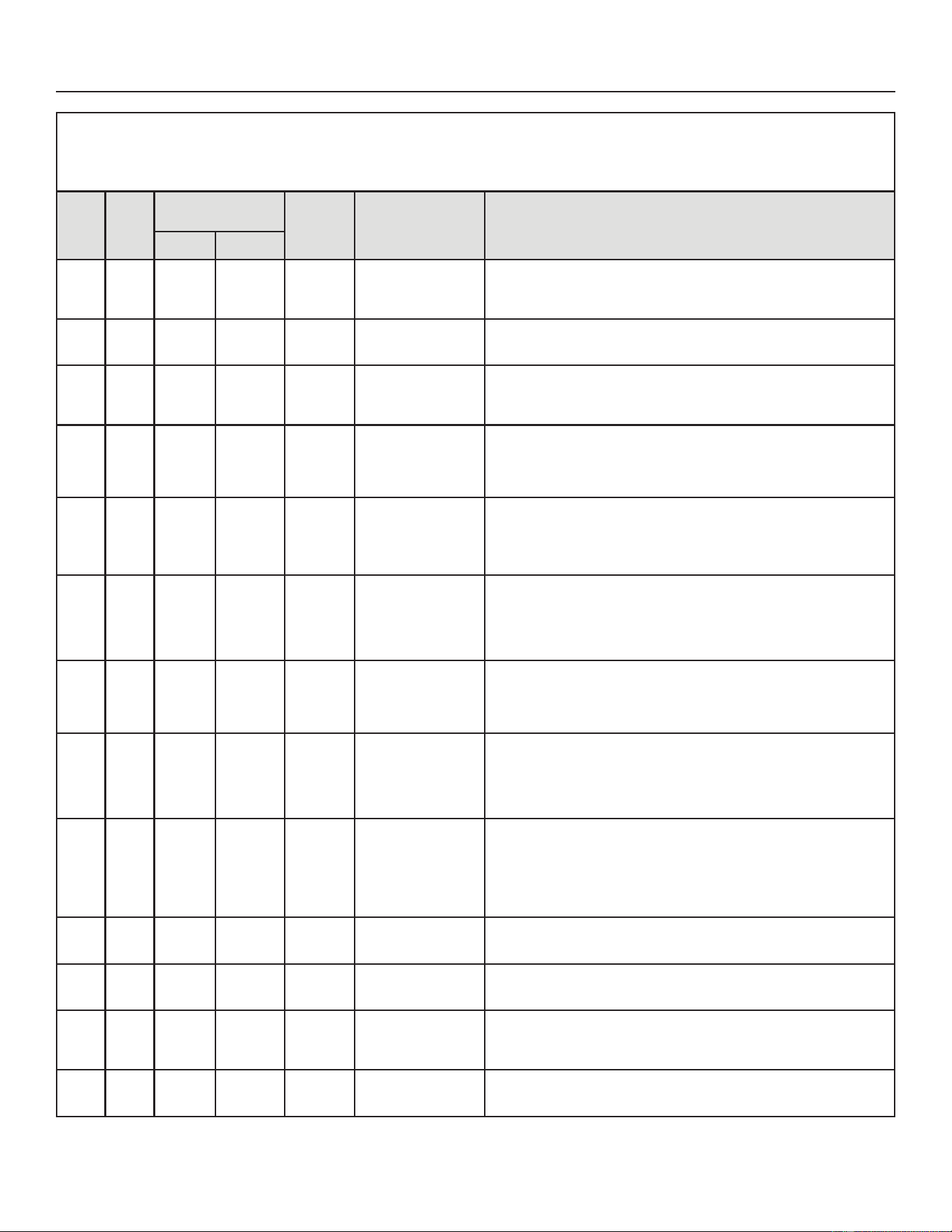
42
31-5000950 Rev. 0
Service Information
Table 7. Outdoor Control 7-Segment Display Alert Codes and Inverter LED Flash Codes
NOTE:6\VWHPIDXOWDQGORFNRXWFRGHVWDNHSUHFHGHQFHRYHUV\VWHPVWDWXVFRGHVFRROLQJKHDWLQJRSHUDWLQJSHUFHQWDJHVRUGHIURVW
GHKXPLGLILFDWLRQ2QO\WKHODWHVWDFWLYHIDXOWRUORFNRXWFRGHVDUHGLVSOD\HGLISUHVHQW,IQRIDXOWRUORFNRXWFRGHVDUHDFWLYHWKHQV\VWHPVWDWXV
codes are displayed.
Alert
Code
Inverter
Code
Inverter Flash Code
QXPEHURIÀDVKHV
Priority Alarm Description Possible Causes and Clearing Alarm
Red LED Green LED
E181 N/A N/A N/A Moderate
Suction pressure
transducer fault.
Suction pressure transducer is out of range. The signal should be between 0.5
VDC and 4.5 VDC between blue and black. The error code will be cleared when
proper signal is provided. System controlled by a conventional 24VAC heat pump
thermostat will operate in the staged mode
E182 N/A N/A N/A Moderate
Suction temperature
sensor has
malfunctioned.
Check temperature sensor in the applicable installation and service procedure.
Nominal resistance is 10K Ohms at 77ºF.
E183 N/A N/A N/A Moderate
Liquid Pressure
Transducer Fault
Liquid pressure transducer is out of range. The signal should be between 0.5 VDC
and 4.5 VDC between Blue and Black. The error code will be cleared when the
proper signal is provided. Systems controlled by a conventional 24VAC heat pump
thermostat will operate in stage mode.
E345 N/A N/A N/A Critical
Heat Pump or Air
Conditioner Alert Code
7KH2UHOD\RQWKH
outdoor board has
failed.
(LWKHUWKHSLORWUHOD\FRQWDFWVGLGQRWFORVHWKHUHOD\FRLOGLGQRWHQHUJL]HWKH
FLUFXLWWKDWFRQ¿UPVWKLVRSHUDWLRQDOVHTXHQFHLVQRWVHQVLQJSURSHUO\
E409 N/A N/A N/A Moderate
Outdoor control
secondary voltage is
18VAC or less.
6HFRQGDU\YROWDJHLVEHORZ9$&$IWHUPLQXWHVRSHUDWLRQLVGLVFRQWLQXHG
Check the indoor line voltage and transformer output voltage. The alarm clears
after the voltage is higher than 20VAC for 2 seconds or after a power reset.
E410 N/A N/A N/A Moderate
The outdoor unit cycled
RႇGXHWRORZVXFWLRQ
pressure.
Unit pressure is below the lower limit. The system is shut down. The suction
SUHVVXUHWUDQVGXFHUHPXODWHVDORZSUHVVXUHVZLWFKWKHXQLWGRHVQRWKDYH
a low pressure switch. The cut-out is set at 40 PSIG and the cut-in set at 90
36,*&RQ¿UPWKDWWKHV\VWHPLVSURSHUO\FKDUJHGZLWKUHIULJHUDQW&KHFN7;9
LQGRRUXQLWEORZHUPRWRU
GLUW\¿OWHUVRUFORJJHGUHIULJHUDQW¿OWHU&RQ¿UPWKDWWKH
evaporator coil is clean. The alarm clears after the pressure rises above 90 PSIG.
E411 N/A N/A N/A Critical
The low pressure fault
has occurred 5 times
within one hour. As a
UHVXOWWKHRXWGRRUXQLW
is locked out.
Low pressure fault error count reached 5 strikes. The low pressure cut-out is at
36,*DQGUHVHWVDW36,*&RQ¿UPWKDWWKHV\VWHPLVSURSHUO\FKDUJHGZLWK
UHIULJHUDQW&KHFNIRUFORJJHG7;9EORFNDJHWRLQGRRUXQLWEORZHUPRWRUGLUW\
¿OWHUVRUFORJJHGUHIULJHUDQW¿OWHU&RQ¿UPWKDWWKHHYDSRUDWRUFRLOLVFOHDQ7KH
alarm clears after a power reset.
E412 N/A N/A N/A Moderate
The outdoor unit high
pressure switch has
opened.
Unit pressure is above the upper limit. System is shut down. The high pressure
VZLWFKRSHQVDW36,*DQGFORVHVDW36,*&RQ¿UPWKDWWKHV\VWHPLV
SURSHUO\FKDUJHGZLWKUHIULJHUDQW&KHFNIRUFORJJHG7;9EORFNDJHWRLQGRRUXQLW
EORZHUPRWRUFORJJHGUHIULJHUDQW¿OWHU&RQ¿UPWKDWWKHRXWGRRUXQLWLVFOHDQ7KH
DODUPFOHDUVDIWHUWKHSUHVVXUHVZLWFKFORVHVRUDSRZHUUHVHW)RUKHDWLQJLQGRRU
&)0PD\EHVHWWRRORZ)RU]RQLQJV\VWHP]RQH&)0PD\EHVHWWRRORZ
E413 N/A N/A N/A Critical
The high pressure
switch has opened 5
times within one hour.
$VDUHVXOWWKHRXWGRRU
unit is locked out.
Open high pressure switch error count reached 5 strikes. System is shut down.
The high pressure switch for R454B opens at 590PSIG and closes at 418PSIG.
&RQ¿UPWKDWWKHV\VWHPLVSURSHUO\FKDUJHGZLWKUHIULJHUDQW&KHFNFRQGHQVHU
IDQPRWRUIRUFORJJHG7;9IRUEORFNDJHWRLQGRRUXQLWEORZHUPRWRUIRUVWXFN
UHYHUVLQJYDOYHRUFORJJHGUHIULJHUDQW¿OWHU&RQ¿UPWKDWWKHRXWGRRUXQLWLVFOHDQ
7KHDODUPFOHDUVDIWHUDSRZHUUHVHW)RUKHDWLQJLQGRRU&)0PD\EHVHWWRRORZ
)RU]RQLQJV\VWHP]RQH&)0PD\EHVHWWRRORZ
E416 N/A N/A
N/A
Moderate /
Critical
The outdoor coil sensor
has malfunctioned.
NS19HKDVD¿[HG.RKPUHVLVWRULQVWDOOHGRQWKHKDUQHVVFRQQHFWRUEHWZHHQ
pins 5 & 6. Check connections on pins 5 & 6 and check for resistance of 10K
ohms. Error code will occur on open or shorted circuit
E422 N/A N/A N/A Moderate
Compressor top cap
switch exceeding
thermal limit.
7KHWRSRIWKHFRPSUHVVRULVKRW5HIULJHUDQWFKDUJHPD\EHORZRUORZPDVVÀRZ
RIUHIULJHUDQW&KHFN7;9FORJJHG¿OWHUGULHUFRQGHQVHUIDQP
RWRULQGRRUEORZHU
PRWRUFRQ¿UPLQGRRUFRLOLVFOHDQ
E423 40 ÀDVKHV OFF
Moderate /
Critical
The inverter has
detected a circuit
problem.
&RQWUROORFNVRXWDIWHUVWULNHVZLWKLQDQKRXU7RFOHDUGLVFRQQHFWSRZHUWRWKH
LQGRRUXQLW9$&SRZHUVRXUFHWRWKHRXWGRRUFRQWUROZKLFKZLOOSRZHURႇWKH
RXWGRRUFRQWURODQGZLOORSHQWKHRXWGRRUXQLWFRQWDFWRUZKLFKLQWHUUXSWVSRZHUWR
the inverter and then re-apply power.
E424 N/A N/A N/A Moderate
The liquid line
temperature sensor has
malfunctioned.
Check connections between pin 3 and 4 of the four pin liquid/suction temperature
plug on the bottom left corner of the control. Check resistance of resistor. Nominal
10K Ohms at 77F. Error code occurs if sensor is open or shorted.
43
31-5000950 Rev. 0
Service Information
Table 7. Outdoor Control 7-Segment Display Alert Codes and Inverter LED Flash Codes
NOTE:6\VWHPIDXOWDQGORFNRXWFRGHVWDNHSUHFHGHQFHRYHUV\VWHPVWDWXVFRGHVFRROLQJKHDWLQJRSHUDWLQJSHUFHQWDJHVRUGHIURVW
GHKXPLGLILFDWLRQ2QO\WKHODWHVWDFWLYHIDXOWRUORFNRXWFRGHVDUHGLVSOD\HGLISUHVHQW,IQRIDXOWRUORFNRXWFRGHVDUHDFWLYHWKHQV\VWHPVWDWXV
codes are displayed.
Alert
Code
Inverter
Code
Inverter Flash Code
QXPEHURIÀDVKHV
Priority Alarm Description Possible Causes and Clearing Alarm
Red LED Green LED
E425 N/A N/A N/A Minor
Outdoor control has
increased minimum
compressor speed
to allow for proper
oil return due to low
ambient temperature.
NOTE - Minimum speed
adjustments begin at
)DQGLQFUHDVHWR
PLQLPXPDW)
Outdoor ambient temperature is below system limit. Control attempts to run at
lowest allowed compressor speed to allow for proper oil return. Automatically
clears when outdoor ambient temperature rises above limit for more than 5
minutes.
E427 21 2 Flashes 1 Flash
Moderate
/ Critical
7KHLQYHUWHUKDVGHWHFWHGD'&SHDNIDXOWFRQGLWLRQ,IFRQGLWLRQ$RUKLJKHULVGHWHFWHGRXWGRRUXQLW
compressor and fan stop. Anti-short cycle is initiated. If peak current (55A or higher) occurs 10 times within
DQKRXUV\VWHPLVORFNHGRXW,QGLFDWHVKLJKSUHVVXUHFRQGHQVHUIDQIDLOXUHORFNHGFRPSUHVVRUURWRURU
RYHUFKDUJH7RFOHDUGLVFRQQHFWSRZHUWRWKHLQGRRUXQLW9$&SRZHUVRXUFHWRWKHRXWGRRUFRQWUROZKLFK
ZLOOSRZHURႇWKHRXWGRRUFRQWURODQGZLOORSHQWKHRXWGRRUXQLWFRQWDFWRUZKLFKLQWHUUXSWVSRZHUWRWKH
inverter and then re-apply power.
E428 22 2 Flashes 2 Flashes
Moderate
/ Critical
The inverter has
detected a high main
input current condition.
,IFRQGLWLRQLVGHWHFWHGLVGHWHFWHGRXWGRRUXQLWFRPSUHVVRUDQGIDQVWRS
$QWLVKRUWF\FOHLVLQLWLDWHG,IFRQGLWLRQRFFXUVWLPHVZLWKLQDQKRXUV\VWHPLV
ORFNHGRXW,QGLFDWHVKLJKSUHVVXUHFRQGHQVHUIDQIDLOXUHRURYHUFKDUJH
7RFOHDUGLVFRQQHFWSRZHUWRWKHLQGRRUXQLW9$&SRZHUVRXUFHWRWKHRXWGRRU
FRQWUROZKLFKZLOOSRZHURႇWKHRXWGRRUFRQWURODQGZLOORSHQWKHRXWGRRUXQLW
FRQWDFWRUZKLFKLQWHUUXSWVSRZHUWRWKHLQYHUWHUDQGWKHQUHDSSO\SRZHU
E429 23 2 Flashes 3 Flashes
Moderate
/ Critical
On a call for
FRPSUHVVRURSHUDWLRQ
if DC link power in
inverter does not rise
above 180 VDC for
DQGWRQPRGHOV
250 VDC for 4 and 5
WRQPRGHOVZLWKLQ
VHFRQGVWKHFRQWURO
will display a moderate
code. If condition is
GHWHFWHGRXWGRRUXQLW
will stop (Compressor
and fan). Antishort
cycles is initiated. If
condition occurs 10
times within a 60 minute
UROOLQJWLPHSHULRG
system will lock out and
display a critical code.
Issues:
(1) If DC link power in inverter does not rise above 180 VDC for 2- and 3-ton
PRGHOV9'&IRUDQGWRQPRGHOVZLWKLQVHFRQGVWKHRXWGRRU
control will display a moderate code.
(2) Capacitors on inverter do not properly charge.
Corrective Actions:
(1) Check for proper main power to outdoor unit and for any loose electrical
connections.
E430 26 2 Flashes 6 Flashes
Moderate
/ Critical
Compressor start failure
,IFRQGLWLRQLVGHWHFWHGRXWGRRUXQLWFRPSUHVVRUDQGIDQVWRS$QWLVKRUWF\FOH
LVLQLWLDWHG,IFRQGLWLRQRFFXUVWLPHVZLWKLQDQKRXUV\VWHPLVORFNHGRXW
,QGLFDWHVSRRUFRQQHFWLRQDWFRPSUHVVRUKDUQHVVLPSURSHUZLQGLQJUHVLVWDQFH
ORFNHGFRPSUHVVRUURWRURUÀRRGHGFRPSUHVVRU
7RFOHDUGLVFRQQHFWSRZHUWRWKHLQGRRUXQLW9$&SRZHUVRXUFHWRWKHRXWGRRU
FRQWUROZKLFKZLOOSRZHURႇWKHRXWGRRUFRQWURODQGZLOORSHQWKHRXWGRRUXQLW
FRQWDFWRUZKLFKLQWHUUXSWVSRZHUWRWKHLQYHUWHUDQGWKHQUHDSSO\SRZHU
44
31-5000950 Rev. 0
Service Information
Table 7. Outdoor Control 7-Segment Display Alert Codes and Inverter LED Flash Codes
NOTE:6\VWHPIDXOWDQGORFNRXWFRGHVWDNHSUHFHGHQFHRYHUV\VWHPVWDWXVFRGHVFRROLQJKHDWLQJRSHUDWLQJSHUFHQWDJHVRUGHIURVW
GHKXPLGLILFDWLRQ2QO\WKHODWHVWDFWLYHIDXOWRUORFNRXWFRGHVDUHGLVSOD\HGLISUHVHQW,IQRIDXOWRUORFNRXWFRGHVDUHDFWLYHWKHQV\VWHPVWDWXV
codes are displayed.
Alert
Code
Inverter
Code
Inverter Flash Code
QXPEHURIÀDVKHV
Priority Alarm Description Possible Causes and Clearing Alarm
Red LED Green LED
E431 27 2 Flashes 7 Flashes
Moderate
/ Critical
Error occurs when PFC
detects an over-current
FRQGLWLRQRI$WKH
control will display a
moderate code. If condition
LVGHWHFWHGRXWGRRUXQLWZLOO
stop (Compressor and fan).
Anti-short cycle is initiated.
Inverter is unavailable
to communicate with
the outdoor control for 3
minutes. If condition occurs
10 times within a 60 minute
UROOLQJWLPHSHULRGV\VWHP
will lock out and display a
critical code.
Issues:
,QGLFDWHVSRZHULQWHUUXSWLRQEURZQRXWSRRUHOHFWULFDOFRQQHFWLRQRUORRVH
inverter input wire.
(2) System testing was set up and code was generated when the reversing
valve is de-energized coming out of defrost (code appears with or without
30 compressor delay).
Corrective Actions:
(1) Check for proper main power to outdoor unit and for any loose electrical
connections.
7RFOHDUGLVFRQQHFWSRZHUWRWKHLQGRRUXQLW9$&SRZHUVRXUFHWRWKH
RXWGRRUFRQWUROZKLFKZLOOSRZHURႇWKHRXWGRRUFRQWURODQGZLOORSHQWKH
RXWGRRUXQLWFRQWDFWRUZKLFKLQWHUUXSWVSRZHUWRWKHLQYHUWHUDQGWKHQUH
apply power.
E432 28 2 Flashes 8 Flashes
Moderate
/ Critical
The inverter has detected
a DC link high voltage
condition
Error occurs when the DC link capacitor voltage is greater than 480VDC. If
FRQGLWLRQLVGHWHFWHGRXWGRRUXQLWFRPSUHVVRUDQGIDQVWRS$QWLVKRUWF\FOH
LVLQLWLDWHG,IFRQGLWLRQRFFXUVWLPHVZLWKLQDQKRXUV\VWHPLVORFNHGRXW
System stops.
7RFOHDUGLVFRQQHFWSRZHUWRWKHLQGRRUXQLW9$&SRZHUVRXUFHWRWKH
RXWGRRUFRQWUROZKLFKZLOOSRZHURႇWKHRXWGRRUFRQWURODQGZLOORSHQWKH
RXWGRRUXQLWFRQWDFWRUZKLFKLQWHUUXSWVSRZHUWRWKHLQYHUWHUDQGWKHQUHDSSO\
power.
E433 29 2 Flashes 9 Flashes
Moderate
/ Critical
The inverter has detected
a compressor over-current
condition.
Error occurs when compressor peak phase current is greater than 28A.
,QYHUWHULVVXHVFRGH¿UVWDQGVORZVGRZQWRWU\WRUHGXFHWKHFXUUHQW,IWKH
FXUUHQWUHPDLQVKLJKRXWGRRUXQLWFRPSUHVVRUDQGIDQVWRS$QWLVKRUWF\FOHLV
LQLWLDWHG,IFRQGLWLRQRFFXUV¿YHWLPHVZLWKLQDQKRXUV\VWHPLVORFNHGRXW
7RFOHDUGLVFRQQHFWSRZHUWRWKHLQGRRUXQLW9$&SRZHUVRXUFHWRWKH
RXWGRRUFRQWUROZKLFKZLOOSRZHURႇWKHRXWGRRUFRQWURODQGZLOORSHQWKH
RXWGRRUXQLWFRQWDFWRUZKLFKLQWHUUXSWVSRZHUWRWKHLQYHUWHUDQGWKHQUHDSSO\
power.
E434 53 5 Flashes 3 Flashes
Moderate
/ Critical
Outdoor control has lost
communications with the
inverter for greater than
3 minutes. Outdoor unit
will stop all compressor
demand. Outdoor control
will attempt to establish
communication multiple
times and will automatically
clear when the error clears.
Unit will lock out after 60
minutes if communication
is not established and will
display a critical error code.
Issues:
2XWGRRUGLVFRQQHFWLVRႇRURXWGRRUSRZHULVRႇZKHQLQGRRUSRZHULVRQ
(source for 24VAC)
(2) Loose electrical power connections
(3) interruption of main power to the inverter
*HQHUDWRUSRZHUVLQGRRUXQLWEXWQRWWKHRXWGRRUXQLW
Corrective Actions:
7RUHVHWF\FOHWKHLQGRRUSRZHURႇVRXUFHRI9$&WRRXWGRRUXQLWDQG
back on. This will de-energize outdoor control and inverter by cycling the
contactor.
(2) Make sure the disconnect is on
(3) check electrical power supply connections
(4) Check for proper main 230V power supply
E435 60 6 Flashes OFF
Moderate
/ Critical
Inverter internal error
:KHQWKLVHUURURFFXUVWKHRXWGRRUFRQWUROF\FOHVSRZHUWRWKHLQYHUWHUE\
opening the contactor for two minutes.
Check that the EEPROM is properly seated. After power is cycled to the
LQYHUWHUWLPHVWKHRXWGRRUXQLWLVORFNHGRXW
,ISUREOHPSHUVLVWVUHSODFHWKHLQYHUWHU
45
31-5000950 Rev. 0
Table 7. Outdoor Control 7-Segment Display Alert Codes and Inverter LED Flash Codes
NOTE:6\VWHPIDXOWDQGORFNRXWFRGHVWDNHSUHFHGHQFHRYHUV\VWHPVWDWXVFRGHVFRROLQJKHDWLQJRSHUDWLQJSHUFHQWDJHVRUGHIURVW
GHKXPLGLILFDWLRQ2QO\WKHODWHVWDFWLYHIDXOWRUORFNRXWFRGHVDUHGLVSOD\HGLISUHVHQW,IQRIDXOWRUORFNRXWFRGHVDUHDFWLYHWKHQV\VWHPVWDWXV
codes are displayed.
Alert
Code
Inverter
Code
Inverter Flash Code
QXPEHURIÀDVKHV
Priority Alarm Description Possible Causes and Clearing Alarm
Red LED Green LED
E436 62 6 Flashes 2 Flashes
Moderate
/ Critical
Inverter heat sink
temperature exceeded limit.
Occurs when the heat sink
temperature exceeds the
inverter limit. Inverter issues
FRGH¿UVWWKHQVORZV
down to allow the heat
sink to cool. If temperature
UHPDLQVKLJKRXWGRRUXQLW
stops (compressor and
fan). Anti-short cycle is
initiated. If condition occurs
WLPHVZLWKLQDQKRXU
system is locked out. To
FOHDUGLVFRQQHFWSRZHU
to the indoor unit (24VAC
power source to the outdoor
control) which will power
RႇWKHRXWGRRUFRQWURODQG
will open the outdoor unit
FRQWDFWRUZKLFKLQWHUUXSWV
power to the inverter and
then re-apply power.
Issue:
This error may occur if the outdoor fan fails to operate or the inverter heat sink
is obstructed with debris.
Feedback from supplier tear down of inverter indicates that the screws
that hold the inverter to the inverter board were loose causing poor contact
between these two components.
Corrective Action:
Tighten screws that hold the heat sink to the inverter control board.
NOTE::DLW¿YHPLQXWHVWRDOORZFDSDFLWRUWRGLVFKDUJHEHIRUHFKHFNLQJ
screws.
E437 65 6 Flashes 5 Flashes
Moderate
/ Critical
Heat sink temperature
sensor fault has occurred
(temperature less than 4ºF
or greater than 264ºF after
10 minutes of operation).
Occurs when the temperature sensor detects a temperature less than 0.4ºF
RUJUHDWHUWKDQ)DIWHUPLQXWHVRIRSHUDWLRQ,IFRQGLWLRQLVGHWHFWHG
outdoor unit will stop (compressor and fan). Anti-short cycle is initiated. If
FRQGLWLRQRFFXUVWLPHVZLWKLQDQKRXUV\VWHPZLOOORFNRXW
7RFOHDUGLVFRQQHFWSRZHUWRWKHLQGRRUXQLW9$&SRZHUVRXUFHWRWKH
RXWGRRUFRQWUROZKLFKZLOOSRZHURႇWKHRXWGRRUFRQWURODQGZLOORSHQWKH
RXWGRRUXQLWFRQWDFWRUZKLFKLQWHUUXSWVSRZHUWRWKHLQYHUWHUDQGWKHQUHDSSO\
power.
,ISUREOHPSHUVLVWVUHSODFHLQYHUWHU
E438 73 7 Flashes 3 Flashes
Moderate
/ Critical
The inverter has detected a
PFC over current condition.
This would be caused by
DKLJKORDGFRQGLWLRQKLJK
SUHVVXUHRURXWGRRUIDQ
failure. Outdoor control will
display the code when the
inverter has the error. After
PLQXWHVWKHLQYHUWHUZLOO
reset and the compressor
will turn on again. If it
happens 10 times within
a 60 minute rolling time
SHULRGWKH2'FRQWUROZLOO
lock out operation of the
outdoor unit and display a
critical code.
Issue:
Possible issue is system running at high pressures. Check for high pressure
trips or other alert codes in room thermostat and outdoor control.
7RFOHDUGLVFRQQHFWSRZHUWRWKHLQGRRUXQLW9$&SRZHUVRXUFHWRWKH
RXWGRRUFRQWUROZKLFKZLOOSRZHURႇWKHRXWGRRUFRQWURODQGZLOORSHQWKH
RXWGRRUXQLWFRQWDFWRUZKLFKLQWHUUXSWVSRZHUWRWKHLQYHUWHUDQGWKHQUHDSSO\
power.
E439 12 1 Flash 2 Flashes Minor
Compressor slowdown due
to high input current.
This error code is primarily for informational purposes as the inverter controls
the compressor to operate within design parameters. Typically the inverter
will make a minor speed reduction of 4 Hz (approximately a 5-6% speed
reduction) for a brief period of time and to reduce the input current and will
then resume normal operation.
Service Information
46
31-5000950 Rev. 0
Table 7. Outdoor Control 7-Segment Display Alert Codes and Inverter LED Flash Codes
NOTE:6\VWHPIDXOWDQGORFNRXWFRGHVWDNHSUHFHGHQFHRYHUV\VWHPVWDWXVFRGHVFRROLQJKHDWLQJRSHUDWLQJSHUFHQWDJHVRUGHIURVW
GHKXPLGLILFDWLRQ2QO\WKHODWHVWDFWLYHIDXOWRUORFNRXWFRGHVDUHGLVSOD\HGLISUHVHQW,IQRIDXOWRUORFNRXWFRGHVDUHDFWLYHWKHQV\VWHPVWDWXV
codes are displayed.
Alert
Code
Inverter
Code
Inverter Flash Code
QXPEHURIÀDVKHV
Priority Alarm Description Possible Causes and Clearing Alarm
Red LED Green LED
E440 13 1 Flash 3 Flashes Minor
Heat sink temperature
is approaching limit.
The compressor speed
utomatically slows to reduce
heat sink temperature.
The control sets indoor
CFM and outdoor RPM
to values according to
demand percentage rather
than the actual Hz. Alarm is
automatically cleared.
This error code is primarily for informational purposes as the inverter controls
the compressor speed to operate within design parameters. Typically the
inverter will make a minor speed reduction of 4 Hz (approximately a 5-6%
speed reduction) for a brief period of time and to reduce the heat sink
temperature and will then resume normal operation. This may occur at
high outdoor temperatures (above 110ºF) for brief periods of time (3 – 4
minutes) and is normal and expected operation of the inverter controlling the
compressor safely within design parameters.
7KHLQYHUWHU¿QQHGDOXPLQXPKHDWVLQNLVORFDWHGRQWKHEDFNVLGHRIWKH
LQYHUWHULQWKHFRQGHQVHUDLUVWUHDPIWKHDOHUWFRGHRFFXUIUHTXHQWO\
HVSHFLDOO\DWORZHURXWGRRUWHPSHUDWXUHVFKHFNWKHKHDWVLQNIRUGHEULVWKDW
PD\UHGXFHKHDWWUDQVIHURUSRVVLEOHREVWUXFWLRQVWKDWPD\LPSDFWDLUÀRZ
across the heat sink.
7KHLQYHUWHUZLOOEHJLQWREULHÀ\UHGXFHWKHFRPSUHVVRUVSHHGZKHQWKHKHDW
sink temperature rises above 185ºF and will allow the inverter to resume the
requested compressor demand speed once the inverter heat sink reaches
176ºF.
E441 14 1 Flash 4 Flashes Minor
Compressor slowdown
due to high compressor
current. Compressor
current is approaching limit.
The compressor speed
automatically slows. The
control sets indoor CFM
and outdoor RPM to values
according to demand
percentage rather than
the actual Hz. Alarm is
automatically cleared.
This error code is primarily for informational purposes as the inverter controls
the compressor to operate within design parameters. Alert code 441 typically
occurs at startup as the compressor as the currently increases rapidly during
startup.
The inverter will reduce the compressor speed by 4 hz and slow the
compressor ramp up speed to the requested compressor demand (capacity).
This is normal and expected operation of the inverter to control the compressor
within design parameters. In most cases the alert code 441 does not require
any additional service or diagnostic procedures.
E441 may also occur if the system is operating at high pressures.
E442 N/A N/A N/A Critical
The top cap switch has
RSHQHG¿YHWLPHVZLWKLQ
RQHKRXU$VDUHVXOWWKH
outdoor unit is locked out.
:KHQFRPSUHVVRUWKHUPDOSURWHFWLRQVHQVRURSHQV¿YHWLPHVZLWKLQRQHKRXU
outdoor stops working.
7RFOHDUGLVFRQQHFWSRZHUWRWKHLQGRRUXQLW9$&SRZHUVRXUFHWRWKH
RXWGRRUFRQWUROZKLFKZLOOSRZHURႇWKHRXWGRRUFRQWURODQGZLOORSHQWKH
RXWGRRUXQLWFRQWDFWRUZKLFKLQWHUUXSWVSRZHUWRWKHLQYHUWHUDQGWKHQUHDSSO\
power.
E443 N/A N/A N/A Critical
Incorrect appliance unit size
code selected.
&KHFNIRUSURSHUFRQ¿JXULQJRIXQLWVL]HFRGHVIRURXWGRRUXQLWLQFRQ¿JXUDWLRQ
JXLGHRULQLQVWDOODWLRQLQVWUXFWLRQV,IUHSODFLQJLQYHUWHUYHULI\LQYHUWHUPRGHO
matches unit size. The alarm/fault clears after the correct match is detected
following a reset. Remove the thermostat from the system while applying
power and reprogramming.
E600 N/A N/A N/A Minor
Compressor has been
cycled OFF on utility load
shedding.
Load shedding function: Provides a method for a local utility company to limit
the maximum power level usage of the outdoor unit. The feature is activated
by applying
E601 N/A N/A N/A Minor
Outdoor unit has been
cycled OFF on low
temperature protection.
Low temperature protection: Outdoor unit will not operate when the outdoor
WHPSHUDWXUHLVDWRUEHORZ)&,IWKHXQLWLVRSHUDWLQJDQGWKHRXWGRRU
WHPSHUDWXUHGURSVEHORZ)&WKHXQLWFRQWLQXHVWRRSHUDWHXQWLOWKH
URRPWKHUPRVWDWLVVDWLV¿HGRUWKHRXWGRRUWHPSHUDWXUHGURSVWR)&
Outdoor unit ambient sensor provides temperature readings.
Service Information
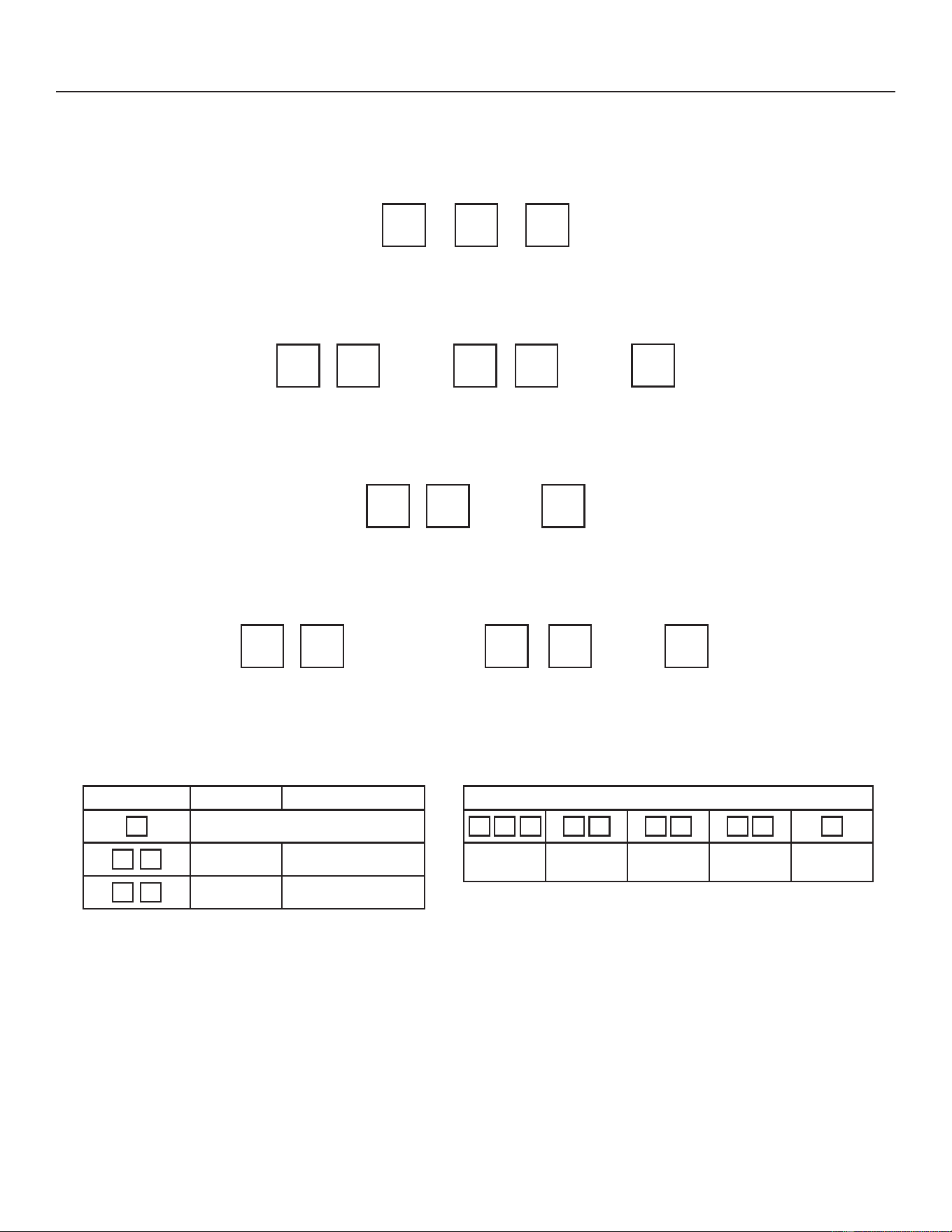
47
31-5000950 Rev. 0
Service Information
POWER-UP / RESET:
FIRMWARE VERSION: 'XULQJLQLWLDOSRZHUXSRUUHVHWWKH¿UVWLWHPGLVSOD\HGLVWKHRXWGRRUFRQWURO¿UPZDUHYHUVLRQ
([DPSOHWRWKHULJKWVKRZV¿UPZDUHYHUVLRQ
•
UNIT TYPE: The next item displayed is the self discovery unit type. AC = air conditioner and HP = heat pump. If the unit
W\SHFDQQRWEHGHWHUPLQHGWKUHHEDUVDSSHDU
D & or + 3 or
UNIT NOMINAL CAPACITY: The next item to be displayed is the self-discovery unit nominal capacity. Valid capacities are
IRUWRQDQGIRUWRQXQLWV,IWKHXQLWW\SHFDQQRWEHGHWHUPLQHGWKUHHEDUVDSSHDU
or
UNIT CODE: This next item to be displayed is the self discovery unit code. (may be a single character or two characters).
,IWKHXQLWFRGHFDQQRWEHGHWHUPLQHGWKUHHEDUVDSSHDU
through or
NOTE -7KHVHDUHMXVWH[DPSOHVRI¿UPZDUHYHUVLRQXQLWW\SHXQLWQRPLQDOFDSDFLW\DQGXQLWFRGHV
Unit Code Model Unit Type and Size
Not Programmed
NS22A36M 3 TON AC Unit
NS22A60M 5 TON AC Unit
7-SEGMENT POWER-UP DISPLAY STRING EXAMPLE
•
$ &
•
Firmware
Version
Unit Type
Unit
Capacity
Unit Code Idle Mode
Figure 18. Outdoor Control 7-Segment Unit Status Displays
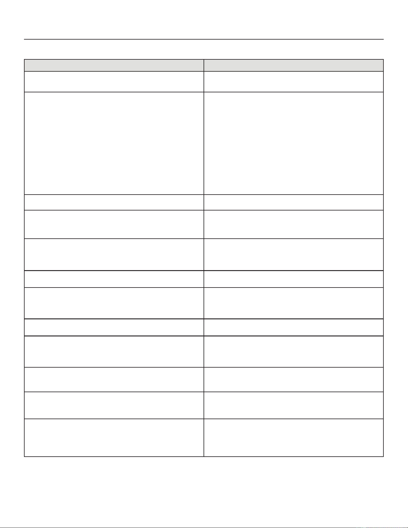
48
31-5000950 Rev. 0
Service Information
Description Example of Display
Idle Mode'HFLPDOSRLQWÀDVKHVDW+]
Idle Mode'HFLPDOSRLQWÀDVKHVDW+]VHFRQGRQVHFRQGRႇ
Display OFF.
Soft Disable Mode: Top and bottom horizontal line and decimal point
ÀDVKDW+]
If indoor or outdoor control displays Soft Disable code:
&RQ¿UPSURSHUZLULQJEHWZHHQDOOGHYLFHVWKHUPRVWDWLQGRRUDQG
outdoor).
2) Cycle power to the control that is displaying the Soft Disable code.
3) Put the room thermostat through Setup.
4) Go to Setup/System Devices/Thermostat/Edit push Reset.
5) Go to Setup/System Devices/Thermostat/Edit push Reset All.
If the room thermostat detects a new device or a device that is not
FRPPXQLFDWLQJLWVHQGVDSoft Disable:KHQWKLVRFFXUVAlarm 10 is
activated and the room thermostat sends a Soft Disable command to the
RႇHQGLQJGHYLFHRQWKHEXVRXWGRRUFRQWURO,)&$+&(,0RU'DPSHU
Control Module).
Soft Disable Mode: Top and bottom horizontal line and decimal point
ÀDVKDW+]VHFRQGRQVHFRQGRႇ
The control in Soft Disable Mode is indicated by the following:
2Q$+&,)&DQGRXWGRRUFRQWUROV6RIW'LVDEOH0RGHLVLQGLFDWHGE\
ÀDVKLQJGRXEOHKRUL]RQWDOOLQHVRQWKHVHJPHQWGLVSOD\
2QWKH'DPSHU&RQWURO0RGXOHDQG(,0WKHJUHHQ/('ZLOOEOLQN
VHFRQGVRQDQGVHFRQGRႇ
O.E.M. Test Mode
$OOVHJPHQWVÀDVKLQJDW+]XQOHVVHUURULVGHWHFWHG127(&RQWURO
should be replaced.
Anti-Short-Cycle Delay
7KHPLGGOHOLQHÀDVKHVDW+]IRUVHFRQGVIROORZHGE\DVHFRQG
display of the number of minutes left on the timer (value is rounded up: 2
PLQVHFLVGLVSOD\HGDV,IDFWLYDWHGWKHDQWLVKRUWF\FOHGHOD\WLPH
remaining is displayed (default is 300 sec./5 min.).
Cooling Capacity: Shows cooling stage C1 or C2 operating if non-
communicating.
&RROLQJFRPSUHVVRUFDSDFLW\VHFRQGRQVHFRQGRႇIROORZHGE\
ambient temperature.
Non-Communicating thermostat with second stage cooling active and
ambient of 95ºF : C 2 pause A 9 5 repeat.
Diagnostic recall: Shows the last 10 stored diagnostic error codes.
,I¿UVWHUURULVE 2 5 0VHFRQGE 2 3 1 pause E 2 5 0 pause E 2 3 1
Next codes (up to 10) are shown using same method.
Fault memory clears
If there are no error codes stored: E pause 0 0 0
$IWHUWKHIDXOWPHPRU\LVFOHDUHGWKHIROORZLQJVWULQJÀDVKHVHYHU\
seconds:
0 0 0 0 pause
Active error in Outdoor Control Idle Mode: Show all active error(s)
codes.
Following display string is repeated if Error E 125 and E 201 are present:
E 1 2 5 pause E 2 0 1
Active error in Run Mode: Show current status and all active error(s)
codes.
Following display string is repeated if Error E 440 is present while cooling
demand is 80 percent:
C 8 0 pause E 4 4 0
Outdoor Ambient Temperature (OAT): Any time OAT is within operating
UDQJHYDOXHLVGLVSOD\HGLIXQLWLVLQGLDJQRVWLFDQGQRQGLDJQRVWLF
modes.
Following display string is repeated if cooling is active and OAT is 104°F:
C 3 5 pause A 1 0 4 pause
Liquid Line Temperature (LIQ): Any time LIQ is sensed in operating
UDQJHYDOXHLVGLVSOD\HGLIXQLWLVLQGLDJQRVWLFPRGHRUPDQXDOO\HQDEOHG
for non-diagnostic modes.
Following display string is repeated if cooling is active and LIQ is 105°F:
C 3 1 pause L 1 0 5 pause
Charge Mode:KHQXQLWLVLQWKHFKDUJHPRGH6XFWLRQSUHVVXUH
63[[[6XFWLRQ7HPS6W[[[6XSHUKHDW6+[[[/LTXLGSUHVVXUH
/3[[[/LTXLG7HPS/W[[[DQGVXEFRROLQJ6&[[[ZLOOEHVFUROOHGRQ
the 7-segment display
The following string is repeated:
S P 1 3 5 pause S t 6 2 pause S H 1 5 pause L P 3 4 5 pause L t 9 6
pause S C 1 0 Repeat
Table 8. Outdoor Control 7-Segment Unit Status Displays
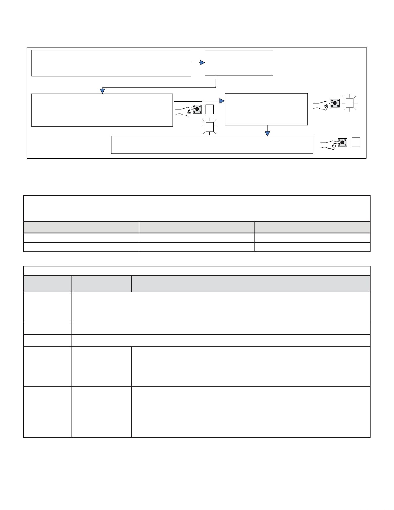
49
31-5000950 Rev. 0
Service Information
UNIT SELECTION CODE FOR OUTDOOR CONTROL
,IWKHVLQJOHFKDUDFWHUGLVSOD\VKRZVWKUHHKRUL]RQWDOOLQHVWKHXQLWVHOHFWLRQFRGHQHHGVWREHSURJUDPPHG3UHVVDQGKROGWKH
button until the P UPHQXRSWLRQLVGLVSOD\HGUHOHDVHEXWWRQ7KHVLQJOHFKDUDFWHUGLVSOD\GLVSOD\VWKHVHOHFWHGPRGHSHUH[DPSOHLQ
Figure 18 on Page 47:KHQWKHGHVLUHGXQLWVHOHFWLRQFRGHDSSHDUVSUHVVDQGKROGWKHEXWWRQXQWLOLWVWRSVÀDVKLQJWKHQUHOHDVH
Unit Code Unit Type Unit Model
A577 3 TON AC Unit NS19H36MA5
79 5 TON AC Unit NS19H60MA5
,GOHPRGH±6\VWHPLVHQHUJL]HGZLWKQRGHPDQG±'HFLPDOÀDVKHVDW+HUW]!VHFRQG21VHFRQG2))
Display Symbol
or Character
Display Fan Test and Display String Option
Displayed
during start-
up or power
recycling
'LVSOD\VWULQJVKRZVRXWGRRUFRQWURO¿UPZDUHYHUVLRQ
B > pause > $& or +3 unit > pause > unit capacity in
%78V!SDXVH!XQLWFRGH,IKRUL]RQWDOEDUVDUHGLVSOD\HGGXULQJDQ\VHTXHQFHRIWKLVGLVSOD\VWULQJLWLQGLFDWHV
WKDWWKHVSHFL¿FSDUDPHWHULVQRWFRQ¿JXUHG
.
Idle mode²GHFLPDOÀDVKHVDW+HUW]!VHFRQG21VHFRQG2))
C
Indicates cooling Capacity. C1 or C2 if conventional 24VAC thermostat
F
Indicates you are in
the Outdoor Fan Test
Mode
Control must be in Idle mode: To enter fan test option - FPRGHSXVKDQGKROGEXWWRQXQWLOVROLG
±DSSHDUVUHOHDVHEXWWRQ'LVSOD\EHJLQVÀDVKLQJ:LWKLQVHFRQGVSXVKDQGKROGEXWWRQXQWLO
required symbol FGLVSOD\VUHOHDVHEXWWRQ'LVSOD\EHJLQVÀDVKLQJ:LWKLQVHFRQGVSXVKDQGKROG
EXWWRQXQWLOGLVSOD\VWRSVÀDVKLQJUHOHDVHEXWWRQ&RQWUROZLOOLQLWLDWHRXWGRRUIDQRSHUDWLRQ2XWGRRU
fan cycles ON for 10 minutes at the highest speed. To exit test – Push and hold button until three
KRUL]RQWDOEDUVGLVSOD\5HOHDVHEXWWRQRXWGRRUIDQF\FOHVOFF.
A
A in the display string
represents the ambient
WHPSHUDWXUHLQ)DWWKH
sensor on the outdoor
unit.
Control can be in Idle or demand mode7RHQWHUGLVSOD\FRQ¿JXUDWLRQRSWLRQ
$PRGHSXVKDQG
KROGEXWWRQXQWLOVROLG±DSSHDUVUHOHDVHEXWWRQ'LVSOD\EHJLQVÀDVKLQJ:LWKLQVHFRQGVSXVK
and hold button until required symbol $GLVSOD\VUHOHDVHEXWWRQ'LVSOD\EHJLQVÀDVKLQJ:LWKLQ
VHFRQGVSXVKDQGKROGEXWWRQXQWLOGLVSOD\VWRSVÀDVKLQJUHOHDVHEXWWRQ'LVSOD\VKRZVHUURU()
code(s) and ambient ( $ RXWGRRUFRLOF) and liquid ( /) temperatures in Fahrenheit.
NOTE,IEXWWRQLVQRWSXVKHGLQWKHVHFRQGWLPHSHULRGWKHFRQWUROH[LWVWKHWHVWPRGH,IWKLV
RFFXUVWHVWPRGHPXVWEHUHSHDWHG
–
–
$
$
386+í%8772123(5$7,21
$OORZV ¿HOG DFFHVV WR 'LDJQRVWLF )DQ 'HIURVW DQG (UURU &RGH
Recall modes.
Outdoor control must be in
IDLE mode (no heating or
cooling operation).
7RHQWHUPRGHRSWLRQVSXVKDQGKROGEXWWRQQH[W
to 7-segment display until DASH symbol appears.
Immediately release the button. Once DASH starts
ÀDVKLQJSURFHHGWRQH[WVWHS
Push and hold button until
mode selection displays on the
7-segment display (D)38BG)
( or F). Immediately release the
EXWWRQSURFHHGWRQH[WVWHS
3XVKDQGKROGEXWWRQXQWLOWKHVHOHFWLRQVWRSVÀDVKLQJWKHQUHOHDVHEXWWRQ7KHVHJPHQW
display shows the selected mode and the control performs the selected function.
Figure 19. Push-Button Operation
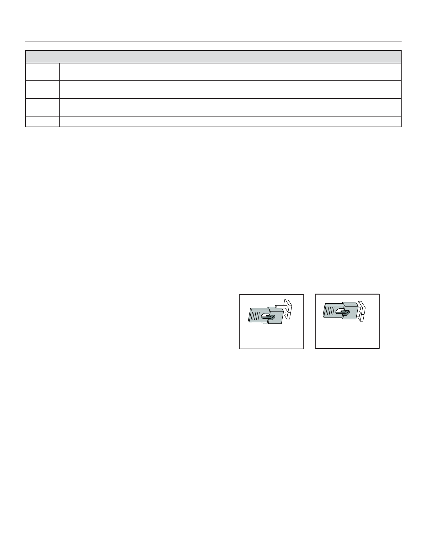
50
31-5000950 Rev. 0
Service Information
FIELD TEST MODE OPERATION
7KH¿HOGWHVWPRGHDOORZVWKHXQLWWREHSXWLQWRGLDJQRVWLF
mode and allows the installer to perform multiple tests on
the control / unit.
Diagnostic Mode
Diagnostic mode is only available when the system is idle
or during an active / suspended call for heating or cooling.
Diagnostic mode is terminated when the exit command is
JLYHQWKHEXWWRQLVSUHVVHGDQGUHOHDVHGZLWKRXWHQWHULQJ
WKHGLDJQRVWLFPHQXRUPLQXWHVKDVSDVVHGZKLFKHYHU
FRPHV¿UVW
When this mode is selected all installed temperature
sensor valves (non-open and non-short) are shown on the
7-segment display. The following system status codes are
displayed:
• Cooling
• Cooling stage or cooling percentage demand operation
• Active error codes
Outdoor Fan Mode
Diagnostic mode is only available while the system is in idle
mode. This mode can be exited with the proper command
or after 10 minutes has passed.
,QGLDJQRVWLFPRGHWKHFRQWUROHQHUJL]HVWKHRXWGRRUIDQDW
the highest speed.
CHARGE MODE OPERATION
To initiate the NS19H&KDUJH0RGHIXQFWLRQLQVWDOOWKH
jumper across the two Charge Mode Pins (CHRG MODE)
on the outdoor control. The Charge Mode can be used
ZKHQFKDUJLQJWKHV\VWHPZLWKUHIULJHUDQWFKHFNLQJ
WKHUHIULJHUDQWFKDUJHSXPSLQJGRZQWKHV\VWHPDQG
performing other service procedures that requires outdoor
unit operation at 100% capacity.
NS19H Charge Mode Operation with a Conventional
24VAC Non-Communicating Thermostat
On applications with a conventional 24VAC non-
FRPPXQLFDWLQJWKHUPRVWDWWKHFKDUJHPRGHMXPSHUPXVW
be installed on the Charge Mode Pins after providing a Y1
cooling demand to the NS19H to initiate the Charge Mode.
A cooling blower demand must also be provided to initiate
blower operation on the cooling speed on the indoor unit.
The compressor and outdoor fan motor will operate at
100% capacity.
7RH[LWWKHFKDUJLQJPRGHUHPRYHWKH&KDUJH0RGH
-XPSHUDQGUHPRYHWKH<&RROLQJGHPDQGDQGLQGRRU
blower demand. The Charge Mode has a maximum time
of 60 minutes and will automatically exit the charge mode
after 60 minutes is the charge mode jumper is left in place.
Error Code Recall Mode (NOTE – control must be in idle mode)
E
7RHQWHUHUURUFRGHUHFDOOPRGHSXVKDQGKROGEXWWRQXQWLOVROLGEDSSHDUVWKHQUHOHDVHEXWWRQ&RQWUROGLVSOD\VXSWR
10 error codes stored in memory. If (LVGLVSOD\HGWKHUHDUHQRVWRUHGHUURUFRGHV
Ł
7RH[LWHUURUFRGHUHFDOOPRGHSXVKDQGKROGEXWWRQXQWLOVROLGWKUHHKRUL]RQWDOEDUVDSSHDUWKHQUHOHDVHEXWWRQ
NOTE - Error codes are not cleared.
c
7RFOHDUHUURUFRGHVVWRUHGLQPHPRU\FRQWLQXHWRKROGEXWWRQZKLOHWKHKRUL]RQWDOEDUVDUHGLVSOD\HG5HOHDVHEXWWRQ
when solid c is displayed.
c
3XVKDQGKROGIRURQHVHFRQGUHOHDVHEXWWRQ6HJPHQWGLVSOD\V and exits error recall mode.
Charge Mode Disabled Charge Mode Enabled
CHRG MODECHRG MODE
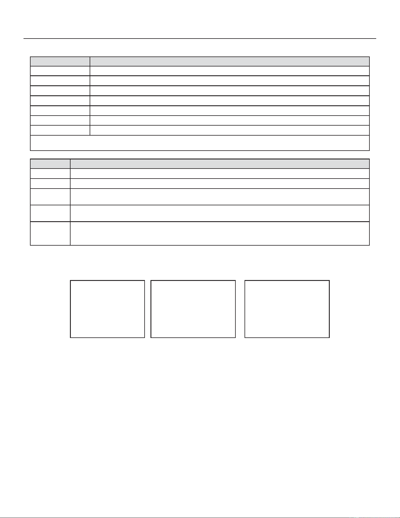
51
31-5000950 Rev. 0
Table 9. Field Test, Diagnostic Recall and Program Menu Options
Display Display and Action (normal operation)
No Change - idle (*) No Change - idle (*)
Solid .
(QWHURUH[LW¿HOGWHVWDQGSURJUDPPRGH
Solid $
Puts unit in diagnostic mode. (Displays ambient temperatures and any active error codes.)
Solid F
Clears error history (**)
Solid (
Enter diagnostic recall mode. Displays up to 10 error codes in memory.
Solid ) Starts outdoor fan.
String 38
Enter unit code programming.
*No change indicates the display will continue to show whatever is currently being displayed for normal operations.
**NOTERQFHWKHHUURUKLVWRU\LVGHOHWHGLWFDQQRWEHUHFRYHUHG$IWHUWKHKLVWRU\LVGHOHWHGWKHXQLWZLOOUHVHWLWVHOI
Display Display and Action (normal operation)
.
,GOHPRGH²GHFLPDOÀDVKHVDW+HUW]!VHFRQG21VHFRQG2))
&
Cooling operation. Shows cooling stage C1 or C2 operating if non-communicating.
(
E in the display string represents the active error code(s) in the outdoor unit.
Example: & pause ( pause ( pause $ pause
$
ALQWKHGLVSOD\VWULQJUHSUHVHQWVWKHRXWGRRUDPELHQWWHPSHUDWXUHLQ)DWWKHRXWGRRUVHQVRURQWKHRXWGRRU
unit. Example: & pause $
Scrolling
:KHQXQLWLVLQWKHFKDUJHPRGH6XFWLRQSUHVVXUH63[[[6XFWLRQ7HPS6W[[[6XSHUKHDW6+[[[/LTXLG
SUHVVXUH/3[[[/LTXLG
7HPS/W[[[DQGVXEFRROLQJ6&[[[ZLOOEHVFUROOHGRQWKHVHJHPHQWGLVSOD\
Example: 63 pause 6W pause 6+ pause /3 pause /W pause 6& Repeat
TYPICAL 7-SEGMENT ACTIVE COOLING DEMAND DISPLAY STRING
&
SECOND STAGE
COOLING DEMAND
H
ACTIVE ERROR
CODE (IF PRESENT)
D
OUTDOOR AMBIENT
AIR TEMP
%\GHIDXOWFRROLQJGHPDQGDFWLYHHUURUFRGHVDQGRXWGRRUDPELHQWWHPSHUDWXUHDUHGLVSOD\HG
Figure 20. Typical 7-Segment Demand Display String
Service Information
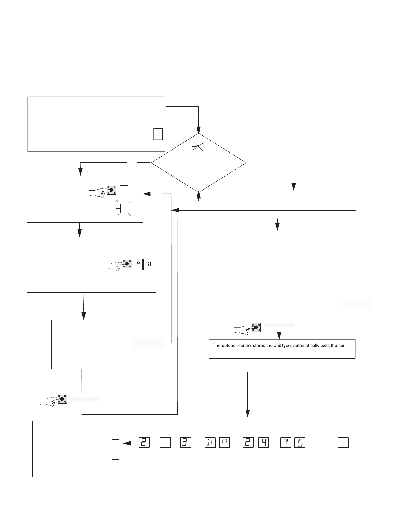
52
31-5000950 Rev. 0
Service Information
CONFIGURING UNIT
:KHQLQVWDOOLQJDUHSODFHPHQWRXWGRRUFRQWUROWKHXQLWVHOHFWLRQFRGHPD\KDYHWREHPDQXDOO\DVVLJQHGXVLQJWKH
VHJPHQWGLVSOD\DQGSXVKEXWWRQRQWKHFRQWURO7KHXQLWFRGHVHWVXQLWW\SHFDSDFLW\DQGRXWGRRUIDQSUR¿OH
Outdoor control is in IDLE mode
(No heating or cooling demand)
Turn room thermostat
to OFF
Push and hold button until the solid
38 sequence is displayed on the
7-segment display then immediately
release the button. This
configuration sequence allows the
installer to select unit selection
code (number combination) that matches
the outdoor unit type and inverter.
If three horizontal bars display in any
part of the 7-segment display string
during power-up, the outdoor
control did not store the unit
selection code. If this occurs, the
configuration sequence for that
section of the display string must be
repeated.
Yes
No
−
−
−
_
_
−
−
−
NOTE - Either the 38 sequence
will repeat 5 times and if a
selection is not made, the control
will return to idle mode.
NOT
SELECTED
SELECTED
Configuring Unit Selection Code
Power-up - Unit selection code (two-digit number) displayed
represents unit size code (outdoor unit capacity).
During initial power-up, firmware version, unit type, unit capacity
and unit selection code will appear on the 7-segment display.
77
79
3-TON AIR CONDITIONER
5-TON AIR CONDITIONER
SELECTED
NOT
SELECTED
UNIT SELECTION
CODE
When the correct unit section code is displayed, release
button immediately. [Display flashes.]
1.
2. Push and hold button until selection stops flashing during
one of the three cycles. [Release push button]
3. If selection is not made during those three cycles the control
returns to idle mode.
figuration mode and resets.
UNIT SELECTION
CODES
Press and hold the button during
the 38 cycling display.
the
UNIT
EXAMPLE 7-SEGMENT DISPLAY STRING
FIRMWARE
VERSION
UNIT
TYPE
UNIT
CAPACITY
UNIT
CODE
.
IDLE MODE
(NO DEMAND)
.
(NS19H36MA5)
(NS19H60MA5)
If three horizontal bars are shown in the 7-segment display
during power-up, the outdoor control did not store the last
configuration setting. If this happens, the configuration
sequence for that setting mush be repeated.
To enter unit selection
mode, push and hold the
button next to the 7-segment
display until DASH symbol
appears and immediately
release button. Once DASH
starts flashing, proceed to next step.
S+
Figure 21. &RQ¿JXULQJ8QLW6HOHFWLRQ&RGH

53
31-5000950 Rev. 0
Service Information
System Overview
Refer to the applicable Thermostat Installer Setup Guide for
FRQ¿JXUDWLRQSURFHGXUHV
The outdoor control provides the following functions:
• Internal switching of outputs.
• Compressor anti-short-cycle delay (adjustable through the
thermostat interface).
• Five-strike lockout function.
• High Pressure protection using the High Pressure Switch
(S4) and Low Suction Pressure protection using the the
suction pressure transducer to emulate the Low Pressure
Switch.
$PELHQW57OLTXLGOLQH57DQGVXFWLRQOLQH57
temperatures for monitoring and protection.
• Suction Pressure Transducer (A168) and Liquid Pressure
Tranducer (A188) for monitoring and control.
COMPRESSOR PROTECTION – FIVE-STRIKE
LOCKOUT
7KH¿YHVWULNHORFNRXWIXQFWLRQLVGHVLJQHGWRSURWHFWWKH
FRPSUHVVRUIURPGDPDJH7KH¿YHVWULNHIHDWXUHLVXVHG
for both high (S4) and low (S87) pressure switches.
Resetting Five-Strike Lockout
2QFHWKHFRQGLWLRQKDVEHHQUHFWL¿HGSRZHUWRWKHRXWGRRU
control R terminal must be cycled OFF.
CRANKCASE HEATER (HR1)
Compressors in all units are equipped with a 40-watt
bellyband-type crankcase heater. HR1 prevents liquid from
accumulating in the compressor. HR1 is controlled by the
crankcase heater thermostat.
Outdoor Unit
0DLQWHQDQFHDQGVHUYLFHPXVWEHSHUIRUPHGE\DTXDOL¿HG
installer or service agency. At the beginning of each cooling
VHDVRQWKHV\VWHPVKRXOGEHFKHFNHGDVIROORZV
&OHDQDQGLQVSHFWRXWGRRUFRLOPD\EHÀXVKHGZLWKD
ZDWHUKRVH(QVXUHSRZHULVRႇEHIRUHFOHDQLQJ
2 - Outdoor unit fan motor is factory-lubricated and sealed.
No further lubrication is needed.
9LVXDOO\LQVSHFWDOOFRQQHFWLQJOLQHVMRLQWVDQGFRLOVIRU
evidence of oil leaks.
4 - Check all wiring for loose connections.
5 - Check for correct voltage at unit (unit operating).
6 - Check amp draw on outdoor fan motor.
7 - Inspect drain holes in coil compartment base and clean
if necessary.
NOTE,ILQVXႈFLHQWKHDWLQJRUFRROLQJRFFXUVWKHXQLW
should be gauged and refrigerant charge should be
checked.
Outdoor Coil
,WPD\EHQHFHVVDU\WRÀXVKWKHRXWGRRUFRLOPRUH
frequently if it is exposed to substances which are corrosive
RUZKLFKEORFNDLUÀRZDFURVVWKHFRLOHJSHWXULQH
FRWWRQZRRGVHHGVIHUWLOL]HUVÀXLGVWKDWPD\FRQWDLQKLJK
levels of corrosive chemicals such as salts).
• Outdoor Coil²7KHRXWGRRUFRLOPD\EHÀXVKHGZLWKD
water hose.
• Outdoor Coil (Coastal Area) — Moist air in ocean
ORFDWLRQVFDQFDUU\VDOWZKLFKLVFRUURVLYHWRPRVWPHWDO
Units that are located near the ocean require frequent
inspections and maintenance. These inspections will
determine the necessary need to wash the unit including
the outdoor coil. Consult your installing contractor for
proper intervals/procedures for your geographic area or
service contract.
Indoor Unit
&OHDQRUFKDQJH¿OWHUV
2 - GE Appliances blower motors are factory-lubricated
and permanently sealed. No more lubrication is needed.
3 - Adjust blower speed for cooling. Measure the pressure
drop over the coil to determine the correct blower CFM.
Refer to the unit information service manual for pressure
drop tables and procedure.
4 - Check all wiring for loose connections.
5 - Check for correct voltage at unit (blower operating).
6 - Check amp draw on blower motor.
Indoor Coil
1 - Clean coil if necessary.
&KHFNFRQQHFWLQJOLQHVMRLQWVDQGFRLOIRUHYLGHQFHRI
oil leaks.
3 - Check condensate line and clean if necessary.
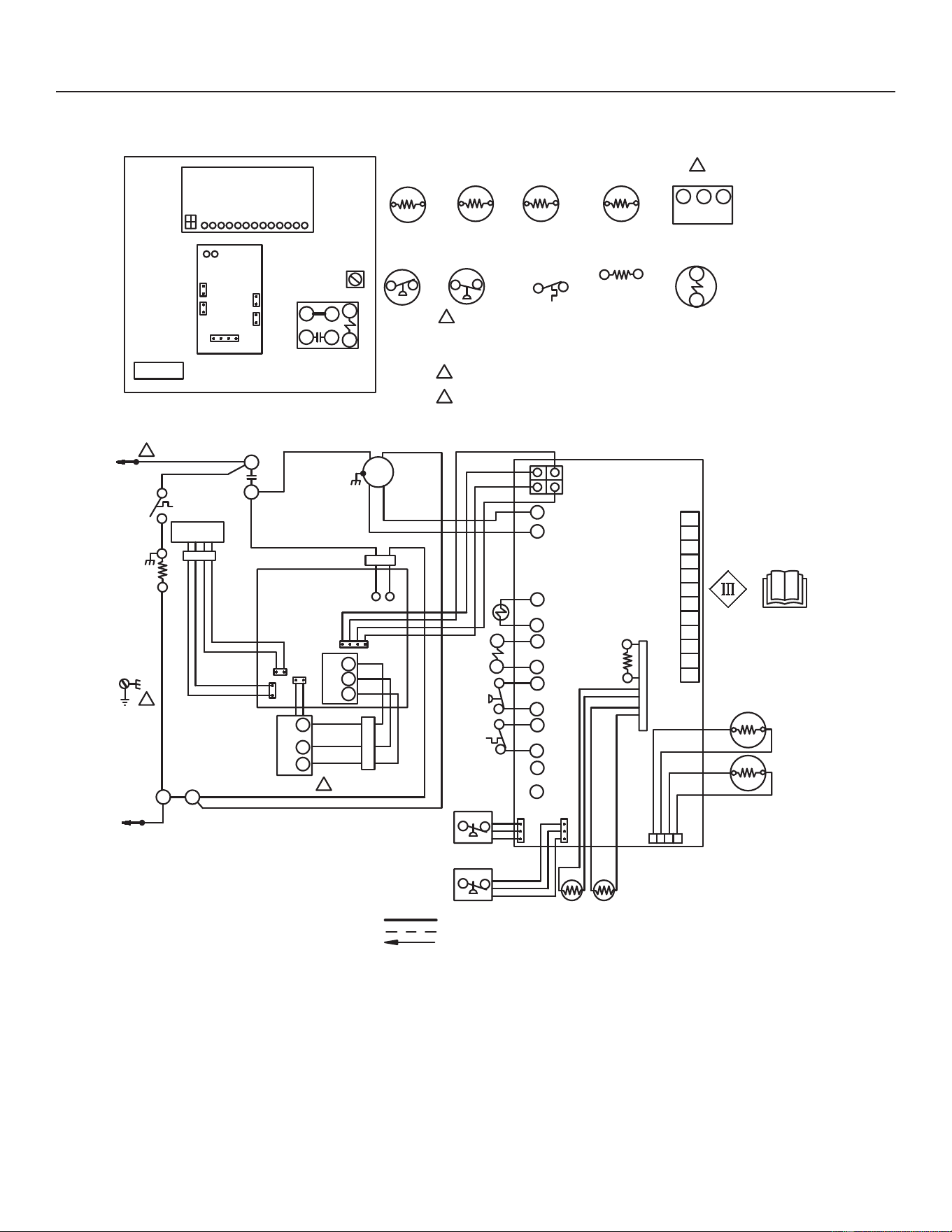
54
31-5000950 Rev. 0
Service Information
Unit Wiring Diagrams
EQUIPMENT
GROUND
2
1
RT13
AMBIENT
SENSOR
S87 LOW
PRESSURE
SWITCH
U
V
W
B1
COMPRESSOR
S4 HIGH
PRESSURE
SWITCH
TP
HPS
LPS
LIQ
AMB
COIL
B4
FAN
K1-2
3
COMPRESSOR
CONTACTOR
S40
HR1
CRANKCASE
THERMOSTAT
CRANKCASE
HEATER
RT36
LIQUID
SENSOR
NOTE-
FOR USE WITH COPPER CONDUCTORS
ONLY. REFER TO UNIT RATING PLATE
FOR MINIMUM CIRCUIT AMPACITY AND
MAXIMUM OVERCURRENT PROTECTION SIZE
REFER TO COMPRESSOR IN UNIT FOR
ACTUAL TERMINAL ARRANGEMENT
COMPRESSOR
CONTACTOR
RED
L2
2
K1-1
RT13
WARNING-ELECTRIC SHOCK HAZARD
CAN CAUSE INJURY OR DEATH. UNIT
MUST BE GROUNDED IN ACCORDANCE
WITH NATIONAL AND LOCAL CODES
BLACK
BROWN
RED
3
REV
CNTCTR
FAN PWM
COM
K1
B
A
REACTOR
BLUE
BLUE
RED
YELLOW
FERRITE
BROWN
FERRITE
FERRITE
INVERTER
S4
S173
S173
COMPRESSOR
TOP CAP SWITCH
COMPRESSOR
2
U
V
W
BLUE
BROWN
CP(L)
CP(N)
U
V
W
BLUE
BROWN
COMM
BROWN
1
R7
RESISTOR
(10K)
RED
BLACK
YELLOW
WHITE
OUTDOOR
CONTROL
L1
4
3
2
1
RT_SUCTION
SENSOR
BLUE
BLUE
R7
RT41
A175
SUCT P
LOW
PRESSURE
TRANSDUCER
A168
1234
RT_LIQUID
SENSOR
RT36
SUCT/
LIQ T
LIQ P
PARK
COM
FAN PWM
GROUND
LUG
K1
COMPRESSOR
CONTACTOR
O OUT
CNTCTR
HI PS
TP
LO PS
INVERTER
REACTOR
O Out
CNCTR
HI PS
TP
LO PS
C
R
O
i
i
-
+
DS
Y2
W
Y1
L
TST
DF
RT21
DEFROST COIL
SENSOR
L1
REVERSING
VALVE
L1
RT21
RT41
SUCTION
SENSOR
HIGH
PRESSURE
TRANSDUCER
A188
WHITE
RED
NOTE-
IF ANY WIRE IN THIS APPLIANCE IS REPLACED,IT
MUST BE REPLACED WITH WIRE OF LIKE SIZE,
RATING, INSULATION THICKNESS, AND TERMINATION.
LINE VOLTAGE FIELD INSTALLED
CLASS II VOLTAGE FIELD WIRING
DENOTES OPTIONAL COMPONENTS
Figure 22. Typical Unit Wiring
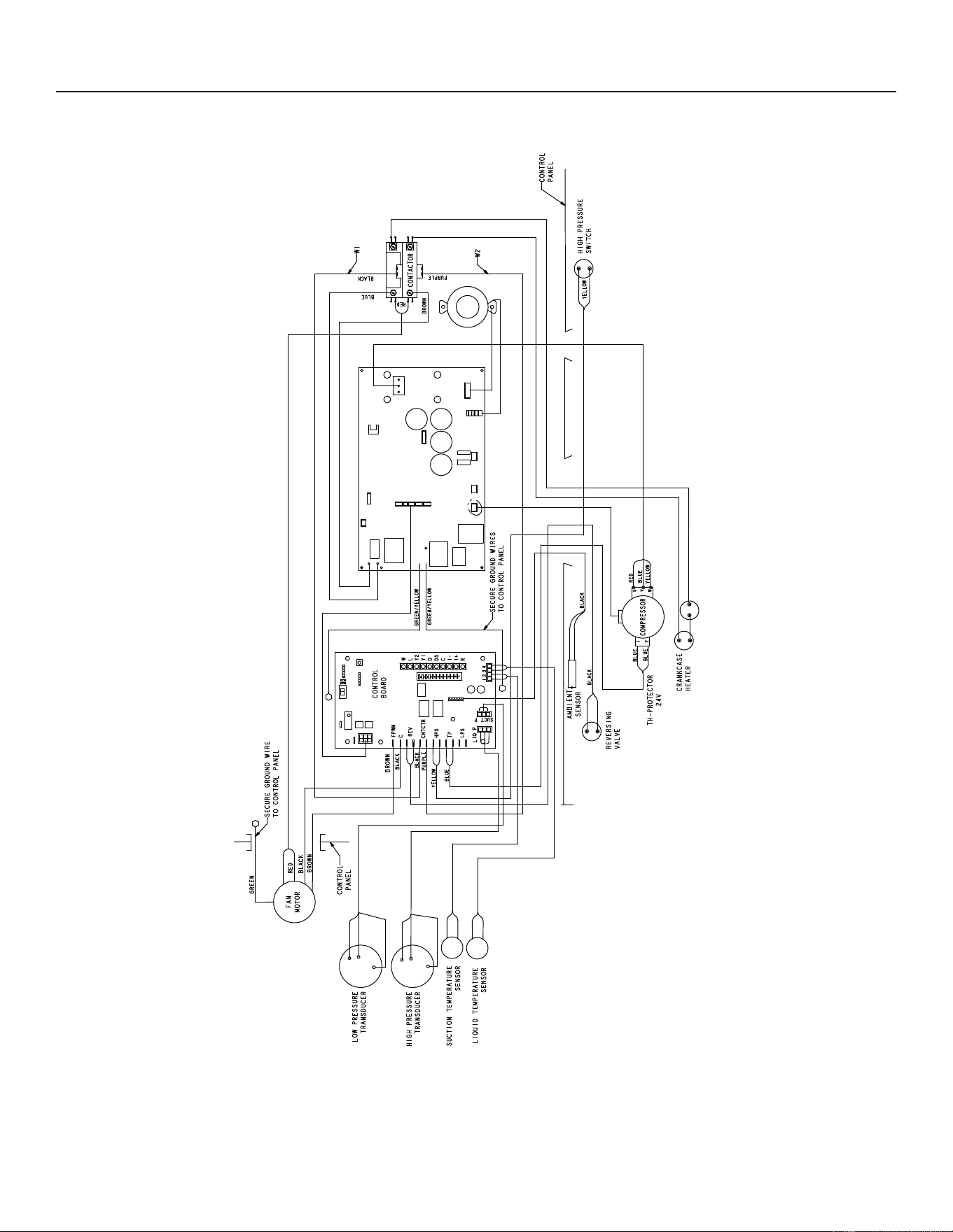
55
31-5000950 Rev. 0
Service Information
Factory Wiring Diagrams
BLACK
BLACK
THERMOSTAT
HEATER
Figure 23. Typical Factory Wiring -036 unit
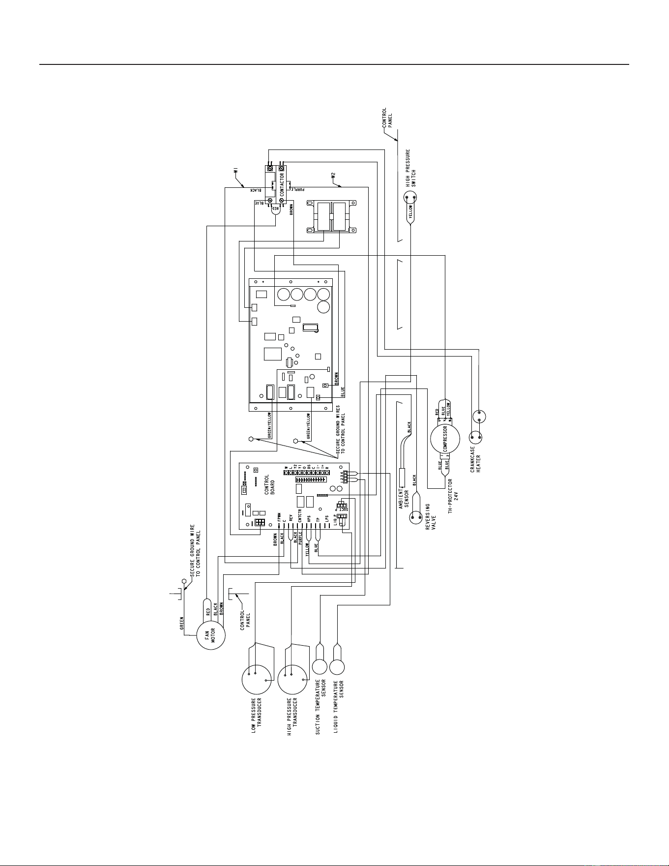
56
31-5000950 Rev. 0
Service Information
Factory Wiring Diagrams
BLACK
BLACK
THERMOSTAT
HEATER
Figure 24. Typical Factory Wiring -060 unit
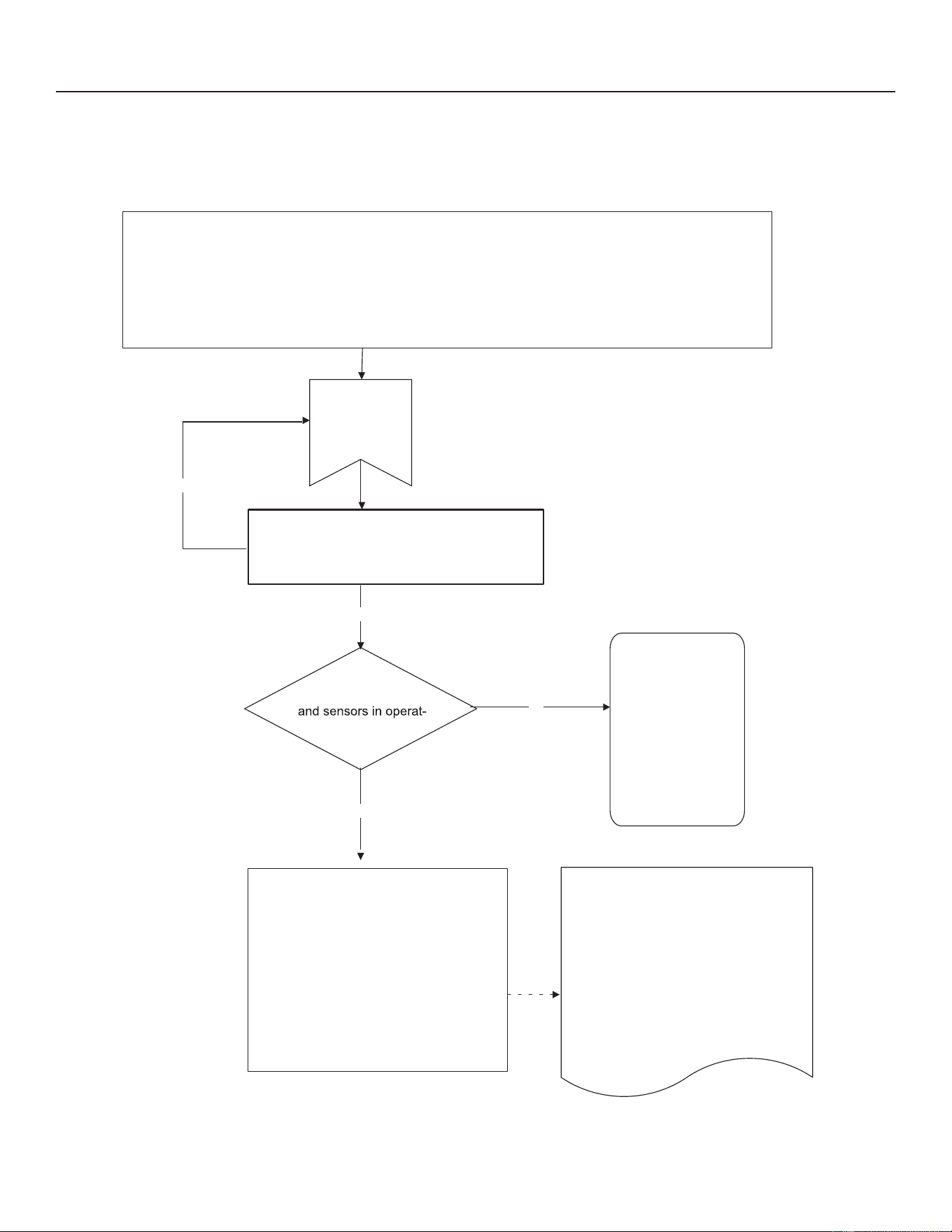
57
31-5000950 Rev. 0
Service Information
UNIT SEQUENCE OF OPERATION
7KHIROORZLQJ¿JXUHVLOOXVWUDWHWKHRYHUDOOXQLWVHTXHQFHRIRSHUDWLRQDORQJZLWKWKHRSHUDWLRQRIYDULRXVSUHVVXUHVZLWFKHV
DQGWHPSHUDWXUHVHQVRUV7KH¿JXUHVDOVRLOOXVWUDWHWKHXVHRIWKHFRPSUHVVRUDQWLVKRUWF\FOHIXQFWLRQLQUHODWLRQWRXQLW
6WDWXVXQLW)DXOWDQGORFNRXW/('&RGHVDQGXQLWV\VWHPRSHUDWLRQLQWHUDFWLRQV
Yes
No
Yes
No
Room thermostat provides a Y1 or Y2 demand to
the main control on systems with a conventional
24VAC thermostat.
All switches closed
ing range.
Check for status or
fault codes in the
outdoor control or
room thermostat.
(NOTE - Refer to low
pressure and high
pressure switch flow
charts for sequence
of operation.
1. View the AIR CONDITIONING screen
for current compressor frequency in
hertz.
2. View the AIR HANDLER screen for
actual CFM of the indoor blower
motor.
From idle mode
Outdoor Control
1. Sends a demand to the compressor
inverter to start and run the
compressor up to the requested
pumping capacity (Frequency in
hertz).
2.
Output signal is provided on PWM
and COM terminals to start and run the
ECM outdoor fan at the demand RPM.
3. Sends a communication signal into
the indoor unit to start and run the
supply fan motor at the demand air
volume (CFM).
On 24 VAC power-up or outdoor reset, the outdoor control shall perform the following tasks:
1. Start the anti-short cycle 3-minute delay in the outdoor control.
2. Check status of the temperature sensor and pressure devices.
3. If the outdoor control does not detect any error codes, outdoor control sends 24 volts out on the
CNTCTR terminals to pull in the contactor coil. (Note - These checks take about 60 seconds.)
4. The contactor contacts pull IN and main power is applied to the compressor inverter.
Diagnostic Screen
Figure 25. 24 Volt Power-Up or Outdoor Reset
Room thermostat provides a Y1 or Y2 demand to
the main control on systems with a conventional
24VAC thermostat.
1. View the HEAT PUMP screen for
current compressor frequency in hertz.
2. View the AIR HANDLER screen
for actual CFM of the indoor blower
motor.
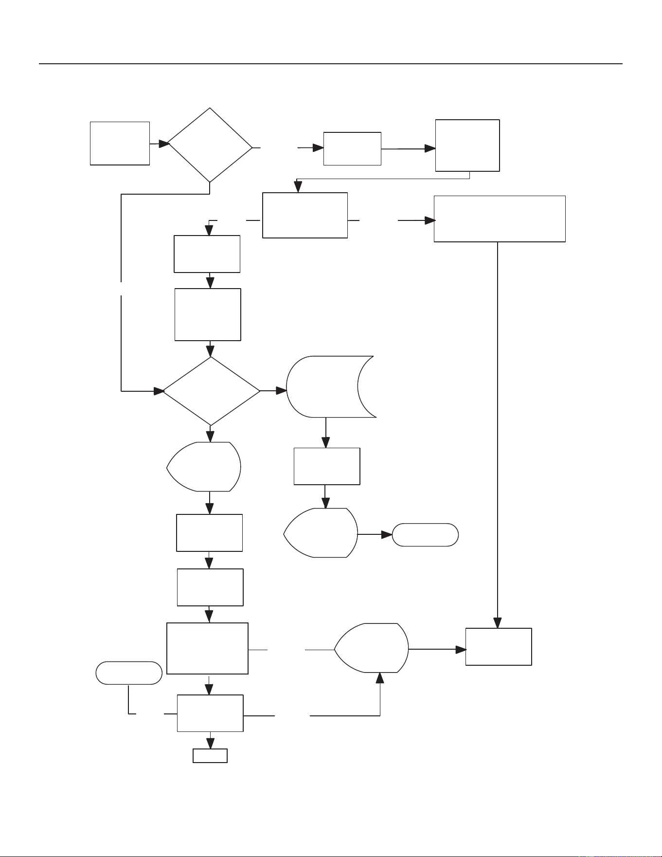
58
31-5000950 Rev. 0
Service Information
UNIT SEQUENCE OF OPERATION
COOLING OR
HEATING
COMPRESSOR
DEMAND
*SUCTION
PRESSURE ABOVE
CUT-OUT OF
35 PSIG
CONTACTOR
ENERGIZED
SUCTION
PRESSURE
CUT-OUT IS
IGNORED FOR
90 SECONDS
SUCTION PRESSURE
ABOVE CUT-OUT
OF 35 PSIG
CONTACTOR
DE-ENERGIZED
ANTI-SHORT
CYCLE TIMER
BEGINS
INCREMENT
5-STRIKE
COUNTER
1
LED ALERT
CODE / OR
MODERATE
ALERT 410
DISPLAYED
ANTI-SHORT
CYCLE TIMER
ENDS
CONTACTOR
ENERGIZED
WAITING FOR
PRESSURE
TO RISE ABOVE
80 PSIG
IS BYPASSED IF OUTDOOR
AMBIENT TEMPERATURE IS 15ºF
OR BELOW
SUCTION PRESSURE CUT-OUT
3
5-STRIKE
COUNTER
REACHES 5
WITHIN A SINGLE
Y1 DEMAND
LOW
PRESSURE
LOCKOUT
LED ALERT
CODE / OR
CRITICAL
ALERT 411
DISPLAYED
SERVICE
REQUIRED
2
LED ALERT
CODE / OR
MODERATE
ALERT 410
DISPLAYED
SERVICE
REQUIRED
2
NORMAL
OPERATION
CLOSED
CLOSED
OPEN
OPEN
OPEN
CLOSED
CLOSED
1.
The thermostat terminates demand when the contactor
is de-energized. If demand is satisfied when alarm is
not active, the 5-strike counter resets.
2.
Lockouts can be reset by cycling power off to the
outdoor control (A175) R terminal.
3. The suction pressure cut-out of 35 psig is ignored by the
system when
the outdoor temperature is below 15°F.
SUCTION
PRESSURE ABOVE
CUT-IN OF
80 PSIG
NO
*Unit does not have a low pressure switch.
The unit has a suction pressure transducer
that emulates the low pressure switch with a
cut-out of 35 PSIG and a cut-in of 80 PSIG.
Figure 26. Low Pressure Switch Emulated by Suction Pressure Transducer
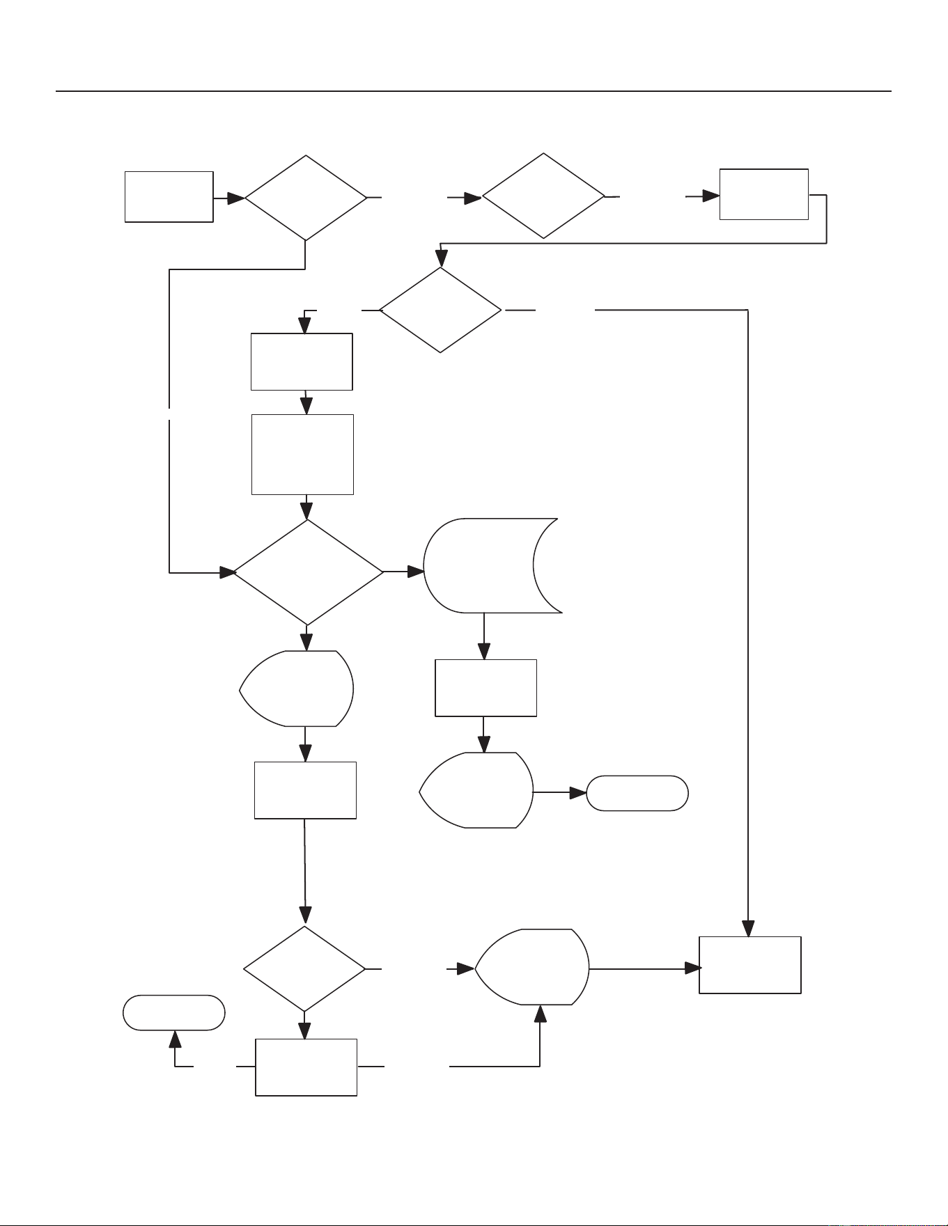
59
31-5000950 Rev. 0
Service Information
UNIT SEQUENCE OF OPERATION
Y1 DEMAND
OR COOLING
DEMAND
HIGH
PRESSURE
SWITCH (S4)
CONTACTOR
ENERGIZED
HIGH
PRESSURE
SWITCH (S4)
CONTACTOR
DE-ENERGIZED
ANTI-SHORT
CYCLE TIMER
BEGINS
INCREMENT
5-STRIKE
COUNTER
1
LED ALERT
CODE / OR
MODERATE
ALERT 412
DISPLAYED
ANTI-SHORT
CYCLE TIMER
ENDS
HIGH
PRESSURE
SWITCH (S4)
WAITING FOR
PRESSURE
SWITCH TO
CLOSE
5-STRIKE
COUNTER
REACHES 5
WITHIN A SINGLE
Y1 DEMAND
HIGH
PRESSURE
SWITCH (S4)
LOCKOUT
LED ALERT
CODE / OR
CRITICAL
ALERT 413
CLEARED
SERVICE
REQUIRED
2
LED ALERT
CODE / OR
MODERATE
ALERT 412
DISPLAYED
NORMAL
OPERATION
CLOSED
CLOSED
OPEN
OPEN
OPEN
CLOSED
CLOSED
TOP CAP
SWITCH (S173)
CLOSED
SERVICE
REQUIRED
2
1. The thermostat terminates demand when the contactor is
de-energized. If demand is satisfied when alarm is not active, the
5-strike counter resets.
2. Lockouts can be reset by cycling power off to the outdoor control
(A175) R terminal.
Figure 27. High Pressure Switch (S4) - (All Versions)
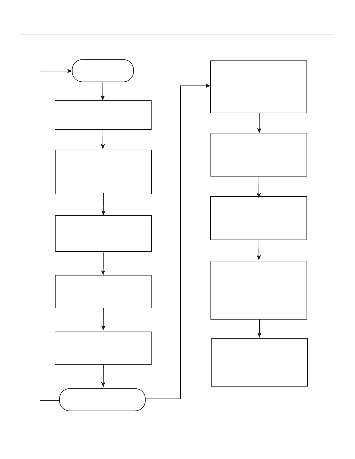
60
31-5000950 Rev. 0
Service Information
UNIT SEQUENCE OF OPERATION
START DEFROST
STATE
ACCUMULATE FROST
ACCUMULATION TIME – HP RUN
TIME IF COIL TEMP BELOW 35°F
IF DEFROST CYCLE TIME IS
CLOSE TO TARGET DEFROST
CYCLE TIME (BETWEEN
80% - 120% TARGET DEFROST
CYCLE TIME) – NO CHANGE IN
FROST ACCUMULATION TIME
INITIATE DEFROST CYCLE IF
FROST ACCUMULATION TIME
EXCEEDS TARGET FROST
ACCUMULATION
TIME (INITIALLY 90 MIN.)
IF DEFROST CYCLE TIME IS
SHORT (80% OR LESS OF
TARGET DEFROST CYCLE TIME)
– FROST ACCUMULATION TIME
INCREASED BY 30 MIN.
DEFROST CYCLE WILL RUN AND
THE TIME IS COMPARED TO
TARGET DEFROST CYCLE TIME
(120S/125S/130S/135S)
DEFROST CYCLE TIME WILL BE
MEASURED UNTIL COIL TEMP
REACHES 50°F
DEFROST WILL TERMINATE
WHEN COIL TEMP REACHES
TERMINATION TEMP
RETURN TO HP HEATING
AND RESET RUN TIMER
IF DEFROST CYCLE TIME IS
LONG (120% OR MORE OF
TARGET DEFROST CYCLE TIME)
– FROST ACCUMULATION TIME
DECREASED BY 30 MIN.
IF DEFROST CYCLE TIME IS
SIGNIFICANTLY LONGER (200%
OR MORE OF TARGET
DEFROST CYCLE TIME)
OR TERMINATES AT 14m MAX
TIME – FROST ACCUMULATION
TIME IS SET TO 30 MIN.
LOW AMBIENT DEFROST
OAT<10F, SET FROST
ACCUMULATION TIME TO 360 MIN.
WHEN OAT INCREASES TO >15F,
RESET FROST
ACCUMULATION TIME TO 90 MIN.
Figure 28. Demand Defrost Cycle
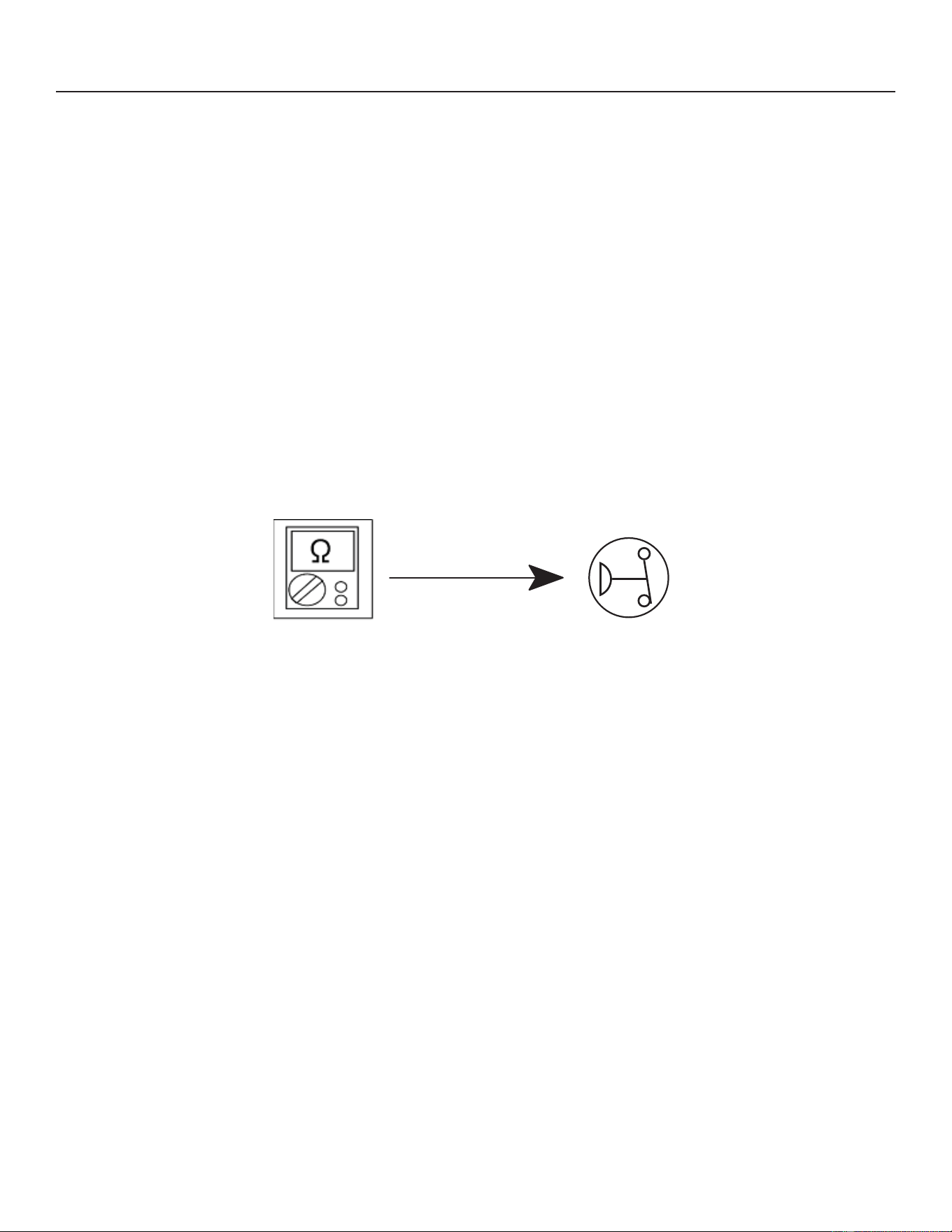
61
31-5000950 Rev. 0
Service Information
COMPONENT TESTING
Verifying High Pressure Switch and Low Pressure Protection Operation:
The unit's pressure switch (HPS - S4) is wired into the control on the HPS terminals.
NOTE – The NS19H does not have a low pressure switch and LPS terminals are not jumpered. The unit has a suction
pressure transducer that emulates the low pressure switch with a cut-out of 35 PSIG and a cut-in of 80 PSIG. This
SURYLGHVWKHVDPHSURWHFWLRQDVDWUDGLWLRQORZSUHVVXUHVZLWFK,IWKHHYHQWWKHVXFWLRQSUHVVXUHWUDQVGXFHUIDLOVEDFNXS
protection is provided by the suction temperature sensor and will open at 25ºF.
• Low Suction Pressure Protection (LPS) – See Figure 25 for low suction pressure protection sequence of operation.
• High Pressure Switch (HPS) – See Figure 26 for high pressure switch sequence of operation.
Pressure Switch Event Settings
The following pressures are the auto-reset event value triggers for low and high pressure thresholds:
• High Pressure (auto-reset) - trip at 590 psig; reset at 418.
• Low Pressure (auto-reset) – trip at 25 psig; reset at 40.
CHECKOUT – S4 High Pressure Switch
8VLQJDPXOWLPHWHUVHWWRRKPVZLWKWKHWHUPLQDOVGLVFRQQHFWHGIURPWKHFRQWUROERDUGFKHFNWKHUHVLVWDQFHEHWZHHQWKH
WZRWHUPLQDOVRIWKHSUHVVXUHVZLWFK,IWKHUHVLVWDQFHUHDGLQJLVRKPVWKHVZLWFKLVFORVHG
Figure 29. Verifying High Pressure Switch Operation
S4 High Pressure Switch
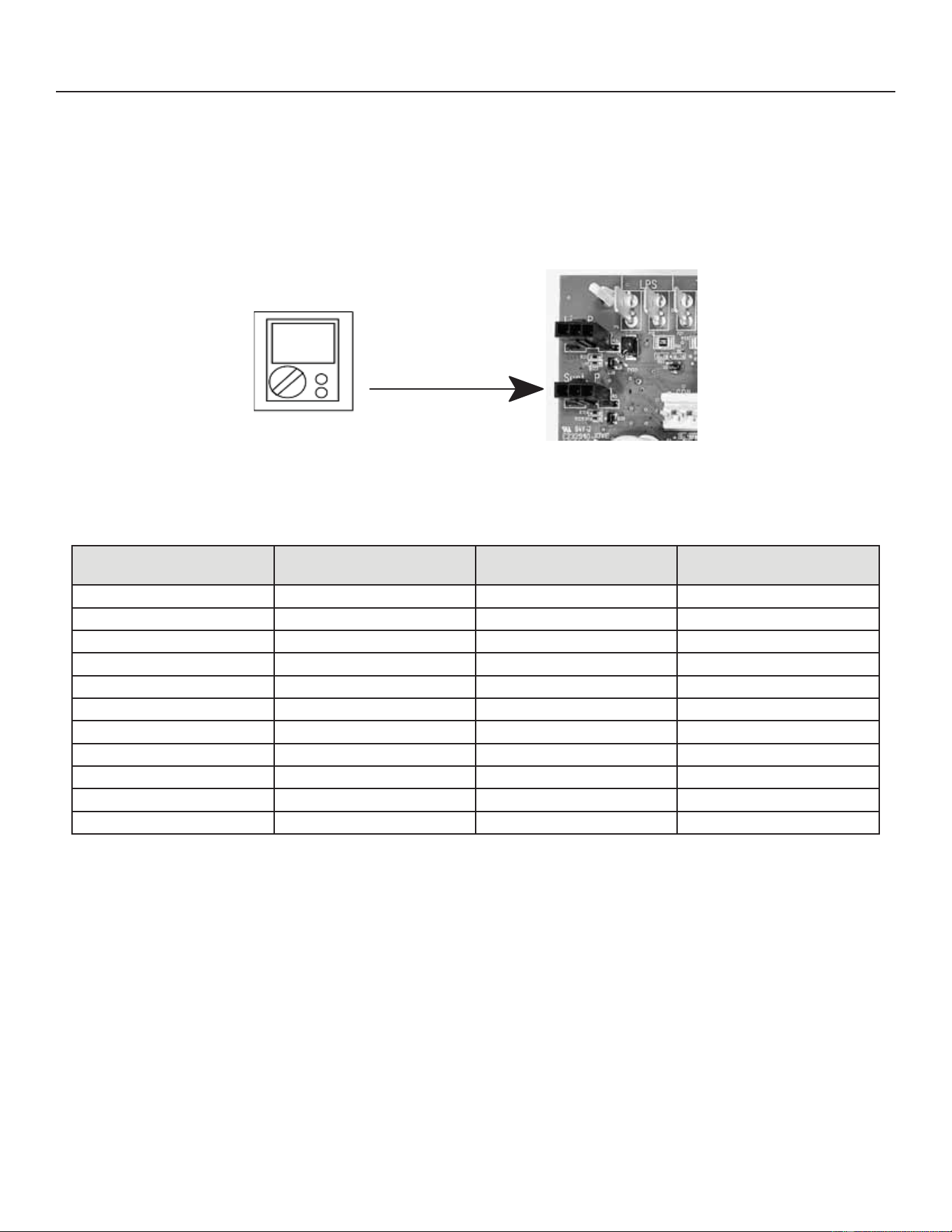
62
31-5000950 Rev. 0
Service Information
COMPONENT TESTING (cont)
Verifying Suction Pressure Transducer Operation
Using a multimeter set to VDC with the Suction Pressure Transducer connected to the “Suct P” 3-pin connector on the
FRQWUROERDUG3LQ5HGZLUH9'&WR3LQ%ODFNZLUH*1'VKRXOGUHDG9'&FRQWLQXRXV3LQ%OXHZLUH
output from transducer) to Pin 3 (Black - GND) should read 0.5 to 4.5 VDC and will vary depending on suction pressure
measured. See Table 10 below.
VDC
Figure 30. Suction Pressure Transducer Voltage
Table 10. Suction Pressure Transducer Output Voltage Table
Suction Pressure
(PSIG)
DC Voltage Output
(Pin 2 to Pin 3)
Suction Pressure
(PSIG)
DC Voltage Output
(Pin 2 to Pin 3)
00.491102.69
10 0.69 120 2.89
20 0.89 130 3.09
30 1.09 140 3.29
40 1.29 150 3.49
50 1.49 160 3.69
60 1.69 170 3.89
70 1.89 180 4.09
80 2.09 190 4.29
90 2.29 200 4.49
100 2.49 210 4.50
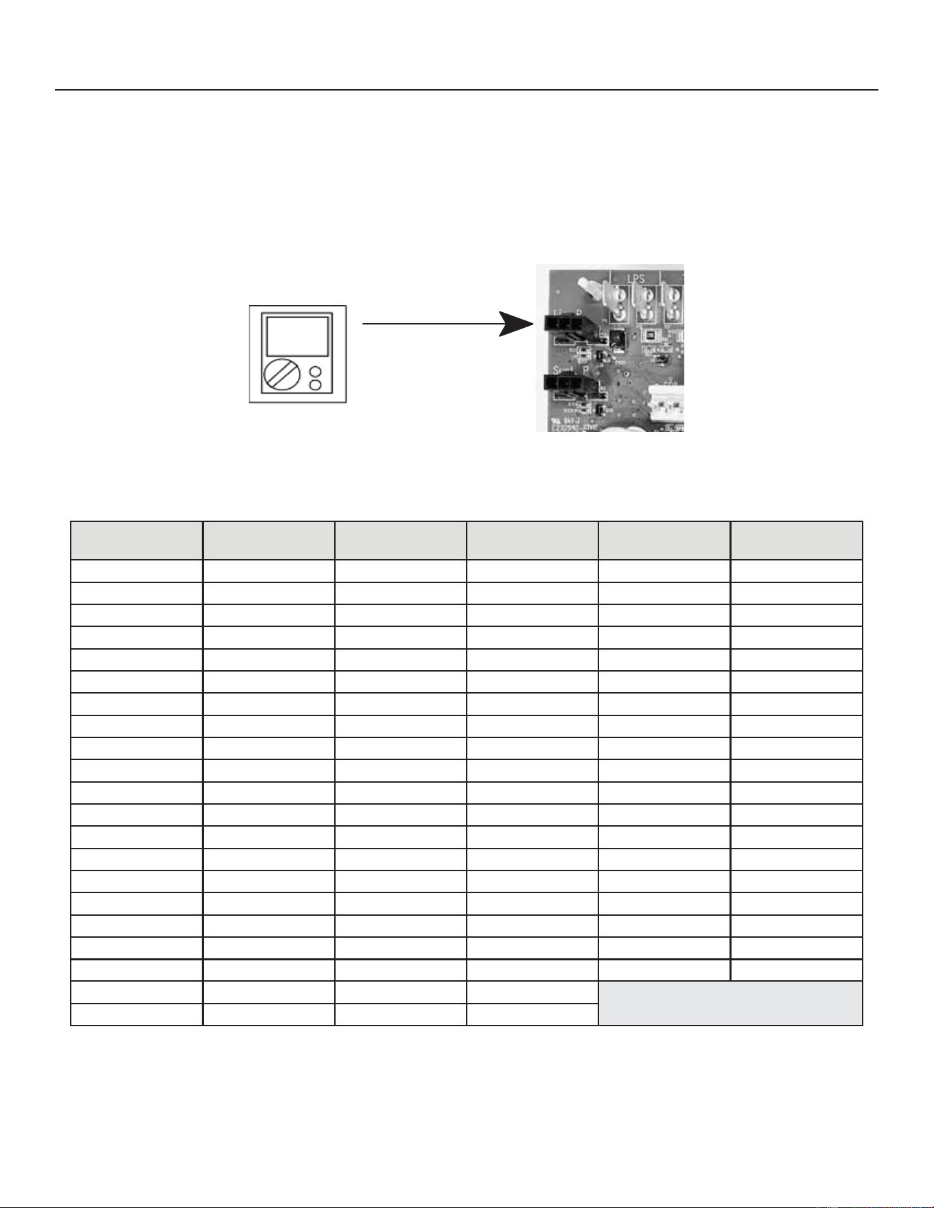
63
31-5000950 Rev. 0
Service Information
COMPONENT TESTING (cont)
Verifying Liquid Pressure Transducer Operation
8VLQJDPXOWLPHWHUVHWWR9'&ZLWKWKH/LTXLG3UHVVXUH7UDQVGXFHUFRQQHFWHGWRWKH/LT3SLQFRQQHFWRURQWKH
FRQWUROERDUG3LQ5HGZLUH9'&WR3LQ%ODFNZLUH*1'VKRXOGUHDG9'&FRQWLQXRXV3LQ%OXHZLUH
output from transducer) to Pin 3 (Black - GND) should read 0.5 to 4.5 VDC and will vary depending on liquid~ pressure
measured. See Table 11 below.
VDC
Figure 31. Liquid Pressure Transducer Voltage
Table 11. Liquid Pressure Transducer Output Voltage Table
Liquid Pressure
(PSIG)
DC Voltage Output
(Pin 2 to Pin 3)
Liquid Pressure
(PSIG)
DC Voltage Output
(Pin 2 to Pin 3)
Liquid Pressure
(PSIG)
DC Voltage Output
(Pin 2 to Pin 3)
0 0.5 210 1.9 420 3.3
10 0.57 220 1.97 430 3.37
20 0.63 230 2.03 440 3.43
30 0.7 240 2.1 450 3.5
40 0.77 250 2.17 460 3.57
50 0.83 260 2.23 470 3.63
60 0.9 270 2.3 480 3.7
70 0.97 280 2.37 490 3.77
80 1.03 290 2.43 500 3.83
90 1.1 300 2.5 510 3.9
100 1.17 310 2.57 520 3.97
110 1.23 320 2.63 530 4.03
120 1.3 330 2.7 540 4.1
130 1.37 340 2.77 550 4.17
140 1.43 350 2.83 560 4.23
150 1.5 360 2.9 570 4.3
160 1.57 370 2.97 580 4.37
170 1.63 380 3.03 590 4.43
180 1.7 390 3.1 600 4.5
190 1.77
400 3.17
200 1.83 410 3.23
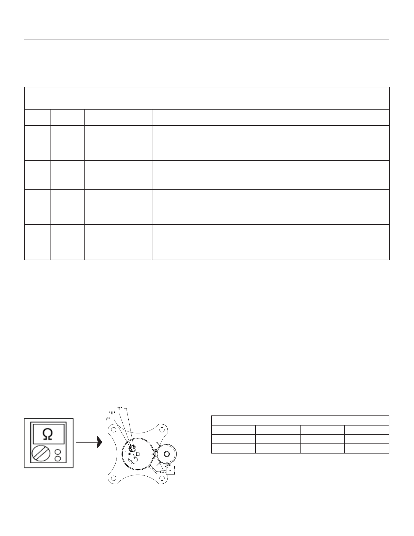
64
31-5000950 Rev. 0
COMPONENT TESTING (cont)
High Pressure Switch Protection Errors
Table 12. Outdoor Control 7-Segment Display Alert Codes
6\VWHPIDXOWDQGORFNRXWFRGHVWDNHSUHFHGHQFHRYHUV\VWHPVWDWXVFRGHVFRROLQJKHDWLQJRSHUDWLQJSHUFHQWDJHVRUGHIURVWGHKXPLGL¿FDWLRQ2QO\
WKHODWHVWDFWLYHIDXOWRUORFNRXWFRGHVDUHGLVSOD\HGLISUHVHQW,IQRIDXOWRUORFNRXWFRGHVDUHDFWLYHWKHQV\VWHPVWDWXVFRGHVDUHGLVSOD\HG$OHUW
codes are also displayed on the communicating thermostat.
Alert
Codes
Priority Alarm Description Possible Causes and Clearing Alarm
E410 Moderate The outdoor unit cycled
RႇGXHWRORZSUHVVXUH
switch opening.
Unit pressure is below the lower limit. The system is shutdown. The low pressure switch closes
DERYHSVLJDQGRSHQVEHORZSVLJ&RQ¿UPWKDWWKHV\VWHPLVSURSHUO\FKDUJHGZLWK
UHIULJHUDQW&KHFN7;9LQGRRUXQLWEORZHUPRWRUGLUW\¿OWHUVRUFORJJHGUHIULJHUDQW¿OWHU&RQ¿UP
that the evaporator coil is clean. The alarm clears after the pressure switch opens or after a
power reset.
E411 Critical The low pressure switch
has opened 5 times within
RQHKRXU$VDUHVXOWWKH
outdoor unit is locked out.
Low pressure switch error count reached 5 strikes. The low pressure switch for R454B opens
DWSVLJDQGUHVHWVDWSVLJ&RQ¿UPWKDWWKHV\VWHPLVSURSHUO\FKDUJHGZLWKUHIULJHUDQW
&KHFNIRUFORJJHG7;9EORFNDJHWRLQGRRUXQLWEORZHUPRWRUGLUW\¿OWHUVRUFORJJHGUHIULJHUDQW
¿OWHU&RQ¿UPWKDWWKHHYDSRUDWRUFRLOLVFOHDQ7KHDODUPFOHDUVDIWHUDSRZHUUHVHW
E412 Moderate The outdoor unit high
pressure switch has
opened.
Unit pressure is above the upper limit. System is shut down. The high pressure switch opens at
SVLJDQGFORVHVDWSVLJ&RQ¿UPWKDWWKHV\VWHPLVSURSHUO\FKDUJHGZLWKUHIULJHUDQW
&KHFNIRUFORJJHG7;9EORFNDJHWRLQGRRUXQLWEORZHUPRWRUFORJJHGUHIULJHUDQW¿OWHU&RQ¿UP
that the outdoor unit is clean. The alarm clears after the pressure switch closes or a power reset.
)RUKHDWLQJLQGRRU&)0PD\EHVHWWRRORZ)RU]RQLQJV\VWHP]RQH&)0PD\EHVHWWRRORZ
E413 Critical The high pressure switch
has opened 5 times within
RQHKRXU$VDUHVXOWWKH
outdoor unit is locked out.
Open high pressure switch error count reached 5 strikes. System is shut down. The high pressure
VZLWFKIRU5%ZLOORSHQDW36,*DQGFORVHDW36,*&RQ¿UPWKDWWKHV\VWHPLVSURSHUO\
FKDUJHGZLWKUHIULJHUDQW&KHFNFRQGHQVHUIDQPRWRUFORJJHG7;9EORFNDJHWRLQGRRUXQLWEORZHU
PRWRUVWXFNUHYHUVLQJYDOYHRUFORJJHGUHIULJHUDQW¿OWHU&RQ¿UPWKDWWKHRXWGRRUXQLWLVFOHDQ7KH
alarm clears after indoor power reset (24VAC power source to Outdoor Control)
Compressor Operation, Checkout and Status / Error Codes
OPERATION:
The NS19HXQLWVXVHD9$&WKUHHSKDVHYDULDEOHFDSDFLW\URWDU\FRPSUHVVRUVSHFL¿FDOO\GHVLJQHGIRUXQLWDU\VSOLWV
V\VWHPDQGLVDSSURYHGIRUXVHZLWK5%UHIULJHUDQW7KHFRPSUHVVRUZKHQFRQQHFWHGWRDQLQYHUWHULVFDSDEOHRI
operating in a running frequency range from 20 hertz up to a maximum of 79 hertz. (maximum hertz is dependent on
compressor size). The compressor speed is determined by thermostat demand and suction pressure when installed with a
conventional 24VAC non-communicating thermostat.
CHECKOUT:
NOTE - The compressor motor winding resistance is the nominal resistance at 77ºF. When measuring compressor motor
ZLQGLQJUHVLVWDQFHWKHSULPDU\FRQFHUQLVWKHZLQGLQJUHVLVWDQFHEHWZHHQWKHGLႇHUHQWVHWVRIWHUPLQDOVLVZLWKLQRI
HDFKRWKHU7KHDFWXDOZLQGLQJUHVLVWDQFHLVLPSDFWHGE\WHPSHUDWXUHUHIULJHUDQWDQGRLO'RQRWDXWRPDWLFDOO\FRQGHPQ
a compressor because the measured resistance is slightly higher or lower than the nominal resistance. Check for shorted/
open windings and for shorts to ground during testing.
Figure 32. Compressor Operation, Checkout and Status/Error Codes
Service Information
Rotary Compressor
Motor Winding Resistance at 77ºF (±7%)
Unit U-V/T1-T2 V-W/T2-T3 W-U/T3-T2
-036 ȍ ȍ ȍ
-060 ȍ ȍ ȍ
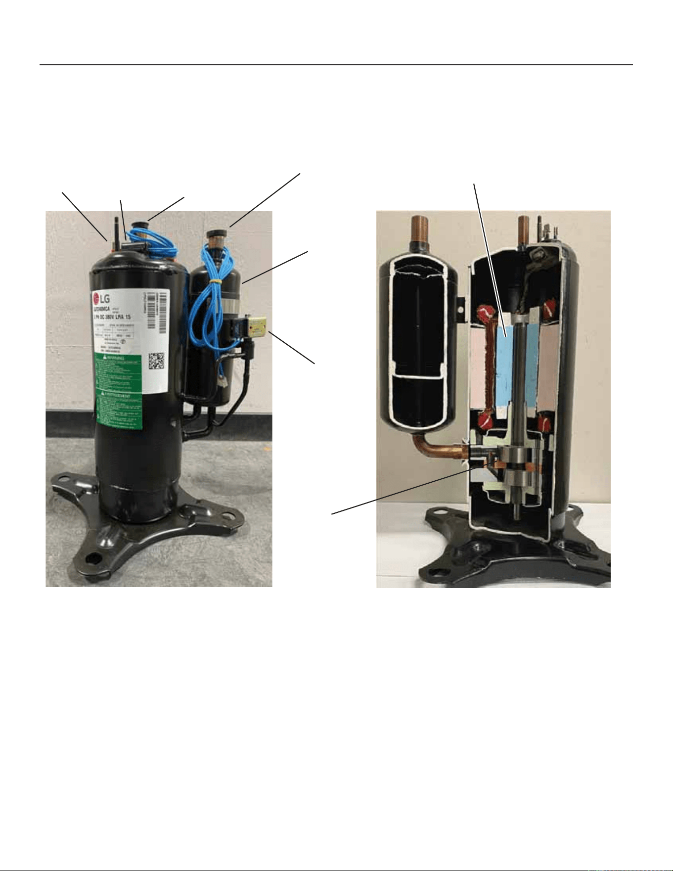
65
31-5000950 Rev. 0
Service Information
COMPONENT TESTING (cont)
IMPORTANT:,IFRPSUHVVRUUHSODFHPHQWLVUHTXLUHGUHPRYHWKHFRPSUHVVRUWKURXJKWKHWRSRIWKHXQLW5HPRYDOWKURXJK
the access panel is not possible.
Electrical
Connection
Plug Location
(not shown)
Top Cap
Thermostat
(S173)
Discharge
Suction
Compressor
Accumulator
Equalization
Valve
Rotary
Compression
Chamber
Compressor
Motor
CUTAWAY OF TYPICAL ROTARY
COMPRESSOR (NOT ACTUAL
NS19H COMPRESSOR)
NS19H ROTARY COMPRESSOR)
Figure 33. NS19H Rotary Compressor Detail
Compressor Equalization Valve
The compressor equalization valve equalization solenoid equalizes the pressure across the rotary compression chamber
allowing the compressor to start unloaded. The 240 VAC solenoid coil is controlled by the inverter.
7KHVROHQRLGFRLOLVSRZHUHGZKHQWKHFRPSUHVVRULVRႇWRHTXDOL]HWKHSUHVVXUHDQGLVGHHQHUJL]HGZKHQWKH
compressor is operating.
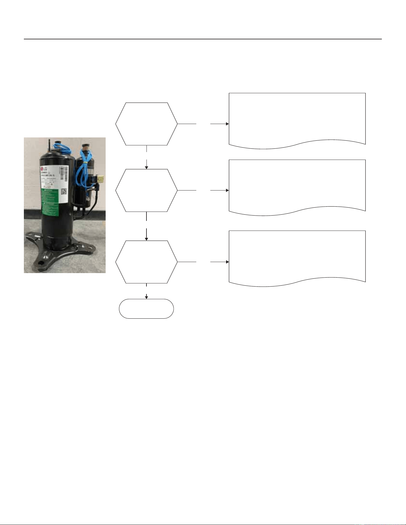
66
31-5000950 Rev. 0
Service Information
COMPONENT TESTING (cont)
STAUS CODES:
:KHQ WKH FRPSUHVVRU LV UXQQLQJ WKH VHJPHQW GLVSOD\ ZLOO VKRZ WKH FRPSUHVVRU FDSDFLW\ :KHQ WKH NS19H unit is
installed with a conventional 24VAC non-communicating thermostat the display will show C 1 or C 2.
Is installation
condition normal?
Is the resistance
between each
phase and insulation
resistance of the
inverter compressor
normal?
Are the compressor
wire connection
conditions normal?
Recheck power and
installaton conditions
NO
NO
NO
YES
YES
YES
1. Check pipe clogging/distortion.
2. Check covering (indoor and outdoor units).
3. Check TXV connector assembly conditional /
normal operation.
4. Check refrigerant operating pressures.
1. Check resistance between each compressor
terminal. (Compare readings with cart below).
2. Check insulation resistance between compressor
terminal and pipe. (Replace compressor
abnormality found).
1. Check for disconnected and lose wiring on
WHUPLQDOV89DQG:DWLQYHUWHUFRQWURO
2. Check for condition of compressor connection
terminals (bad contacts).
3. Check refrigerant operating pressures.
Figure 34. Compressor Operation, Checkout and Status/Error Codes
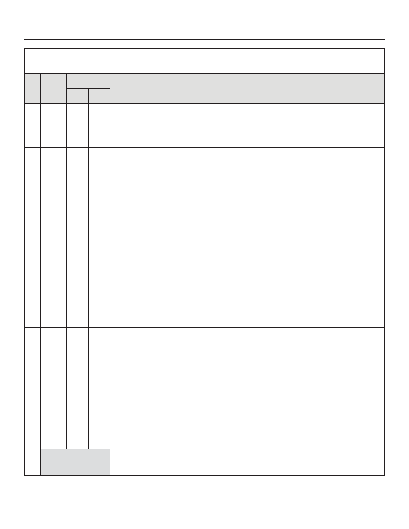
67
31-5000950 Rev. 0
Service Information
Table 13. Outdoor Control 7-Segment Display Alert Codes - Compressor
6\VWHPIDXOWDQGORFNRXWFRGHVWDNHSUHFHGHQFHRYHUV\VWHPVWDWXVFRGHVFRROLQJKHDWLQJRSHUDWLQJSHUFHQWDJHVRUGHIURVWGHKXPLGLILFDWLRQ2QO\WKHODWHVWDFWLYH
IDXOWRUORFNRXWFRGHVDUHGLVSOD\HGLISUHVHQW,IQRIDXOWRUORFNRXWFRGHVDUHDFWLYHWKHQV\VWHPVWDWXVFRGHVDUHGLVSOD\HG
Alert
Code
Inverter
Code
Inverter Flash
Code
Priority
Condition
Actual Displayed
Alert Text
Possible Causes and Clearing Alarm
Red
LED
Green
LED
E 430 26
2
ÀDVKHV
6
ÀDVKHV
Moderate /
Critical
Compressor
Startup Fail
,I FRQGLWLRQ LV GHWHFWHG RXWGRRUXQLW FRPSUHVVRU DQG IDQVWRS$QWLVKRUW F\FOH LVLQLWLDWHG ,I
FRQGLWLRQ RFFXUV WLPHV ZLWKLQ DQ KRXU V\VWHP LV ORFNHG RXW ,QGLFDWHV SRRU FRQQHFWLRQ
DW FRPSUHVVRU KDUQHVV LPSURSHU ZLQGLQJ UHVLVWDQFH ORFNHG FRPSUHVVRU URWRU RU ÀRRGHG
compressor.
7RFOHDUGLVFRQQHFWSRZHUWRWKHLQGRRUXQLW9$&SRZHUVRXUFHWRWKHRXWGRRUFRQWUROZKLFK
ZLOO SRZHU Rႇ WKH RXWGRRU FRQWURO DQG ZLOO RSHQ WKH RXWGRRU XQLW FRQWDFWRU ZKLFK LQWHUUXSWV
power to the inverter and then re-apply power.
E 433 29
2
ÀDVKHV
9
ÀDVKHV
Moderate /
Critical
The inverter
has detected
a compressor
overcurrent
condition.
Error occurs when compressor peak phase current is greater than 28A. Inverter issues code
¿UVWDQGVORZVGRZQWRWU\WRUHGXFHWKHFXUUHQW,IWKHFXUUHQWUHPDLQVKLJKRXWGRRUXQLW
FRPSUHVVRUDQGIDQVWRS$QWLVKRUWF\FOHLVLQLWLDWHG,IFRQGLWLRQRFFXUVWLPHVZLWKLQDQKRXU
system is locked out.
7RFOHDUGLVFRQQHFWSRZHUWRWKHLQGRRUXQLW9$&SRZHUVRXUFHWRWKHRXWGRRUFRQWUROZKLFK
ZLOO SRZHU Rႇ WKH RXWGRRU FRQWURO DQG ZLOO RSHQ WKH RXWGRRU XQLW FRQWDFWRU ZKLFK LQWHUUXSWV
power to the inverter and then re-apply power.
E 439 12 ÀDVK
2
ÀDVKHV
Moderate
Compressor
slowdown due to
high input current.
Input current is approaching a high limit. Compressor speed automatically slows. The control
continues sending the inverter speed demanded by the thermostat. The control sets indoor
CFM and outdoor RPM to values according to demand percentage rather than the actual Hz.
Alarm is automatically clear.
E 440 13 ÀDVK
3
ÀDVKHV
Minor
Heat sink
temperature is
approaching limit.
The compressor
speed
automatically
slows to reduce
heat sink
temperature.
The control sets
indoor CFM and
outdoor RPM to
values according
to demand
percentage
rather than the
actual Hz. Alarm
is automatically
cleared.
This error code is primarily for informational purposes as the inverter controls the compressor
speed to operate within design parameters. Typically the inverter will make a minor speed
reduction of 4 Hz (approximately a 5-6% speed reduction) for a brief period of time and to
reduce the heat sink temperature and will then resume normal operation. This may occur at high
outdoor temperatures (above 110ºF) for brief periods of time (3 – 4 minutes) and is normal and
expected operation of the inverter controlling the compressor safely within design parameters.
7KHLQYHUWHU¿QQHGDOXPLQXPKHDWVLQNLVORFDWHGRQWKHEDFNVL
GHRIWKHLQYHUWHULQWKHFRQGHQVHU
DLU VWUHDP ,I WKHDOHUW FRGH RFFXUIUHTXHQWO\ HVSHFLDOO\DW ORZHU RXWGRRU WHPSHUDWXUHV
check the heat sink for debris that may reduce heat transfer or possible obstructions that may
LPSDFWDLUÀRZDFURVVWKHKHDWVLQN
7KHLQYHUWHUZLOOEHJLQWREULHÀ\UHGXFHWKHFRPSUHVVRUVSHHGZKHQWKHKHDWVLQNWHPSHUDWXUH
rises above 185ºF and will allow the inverter to resume the requested compressor demand
speed once the inverter heat sink reaches 176ºF.
E 441 14 ÀDVK
4
ÀDVKHV
Minor
Compressor
slowdown due to
high compressor
current.
Compressor
current is
approaching limit.
The compressor
speed
automatically
slows. The
control sets
indoor CFM and
outdoor RPM to
values according
to demand
percentage
rather than the
actual Hz. Alarm
is automatically
cleared
This error code is primarily for informational purposes as the inverter controls the compressor to
operate within design parameters. Alert code 441 typically occurs at startup as the compressor
as the currently increases rapidly during startup.
The inverter will reduce the compressor speed by 4 hz and slow the compressor ramp up speed
to the requested compressor demand (capacity). This is normal and expected operation of the
inverter to control the compressor within design parameters. In most cases the alert code 441
does not require any additional service or diagnostic procedures.
E441 may also occur if the system is operating at high pressures.
600 N/A Critical
Compressor has
been cycled OFF
by utility load-
shedding function.
Load-shedding function: Provides a method for a local utility company to limit the maximum
power level usage of the outdoor unit. The feature is activated by applying 24 volts AC power to
the L and C terminals on the outdoor control.
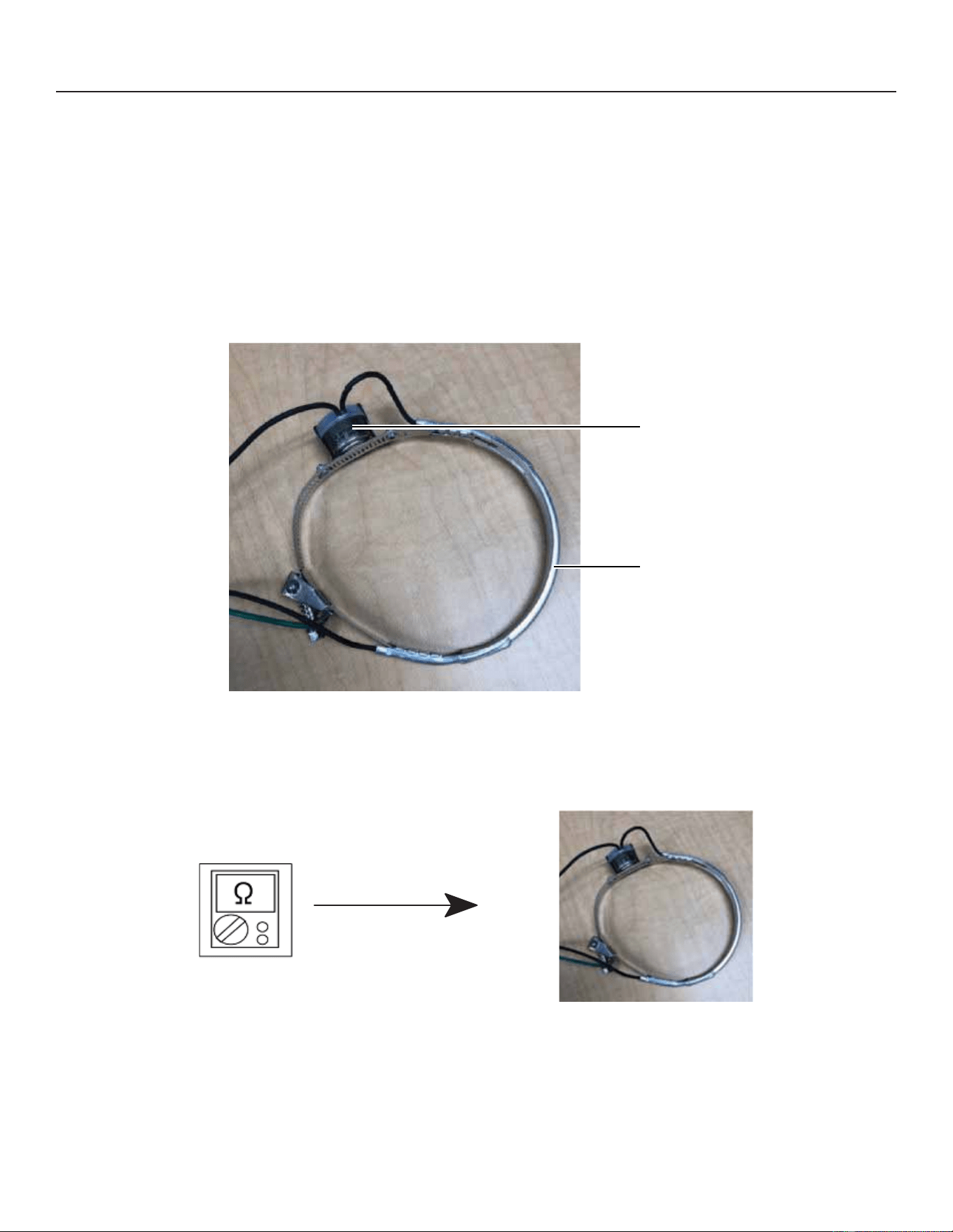
68
31-5000950 Rev. 0
Service Information
CRANKCASE HEATER, CHECKOUT AND STATUS / ERROR CODES
OPERATION:
CRANKCASE HEATER (HR1)
Compressors in all units are equipped with a 40 watt belly-band type crankcase heater. The heater prevents liquid from
accumulating in the compressor. The heater is controlled by the crankcase heater thermostat.
CRANKCASE HEATER THERMOSTAT (S40)
Crankcase heater thermostat S40 controls the crankcase heater in all units and is integrated onto the heater.
:KHQFRPSUHVVRUWHPSHUDWXUHGURSVEHORZ)WKHWKHUPRVWDWFORVHVZKLFKUHVXOWVLQWKHKHDWHUEHLQJHQHUJL]HG
:KHQFRPSUHVVRUWHPSHUDWXUHULVHVDERYH)WKHWKHUPRVWDWRSHQVZKLFKUHVXOWVLQWKHKHDWHUEHLQJGHHQHUJL]HG
Thermostat
Heater
Figure 35. Belly-Band Crankcase Heater with Thermostat
CHECKOUT:
Belly-Band Crankcase Heater:8VLQJPHWHUVHWRQRKPVFKHFNFUDQNFDVHKHDWHUUHVLVWDQFH,IUHVLVWDQFHLVRKPVRU
LQ¿QLWHUHSODFHWKHFUDQNFDVHKHDWHU
Figure 36. Checking Belly-Band Crankcase Heater
Crankcase Heater Thermostat:$VWKHGHWHFWHGWHPSHUDWXUHFKDQJHVWKHUHVLVWDQFHDFURVVWKHVHQVRUFKDQJHVTable
17 shows how the resistance varies as the temperature changes for this sensor.
NOTE±:KHQFKHFNLQJWKHRKPVDFURVVDVHQVRUEHDZDUHWKDWDVHQVRUVKRZLQJDUHVLVWDQFHYDOXHWKDWLVQRWZLWKLQ
WKHUDQJHPD\EHSHUIRUPLQJDVGHVLJQHG+RZHYHULIDVKRUWHGRURSHQFLUFXLWLVGHWHFWHGWKHVHQVRULVIDXOW\WKH
sensor needs to be replaced.
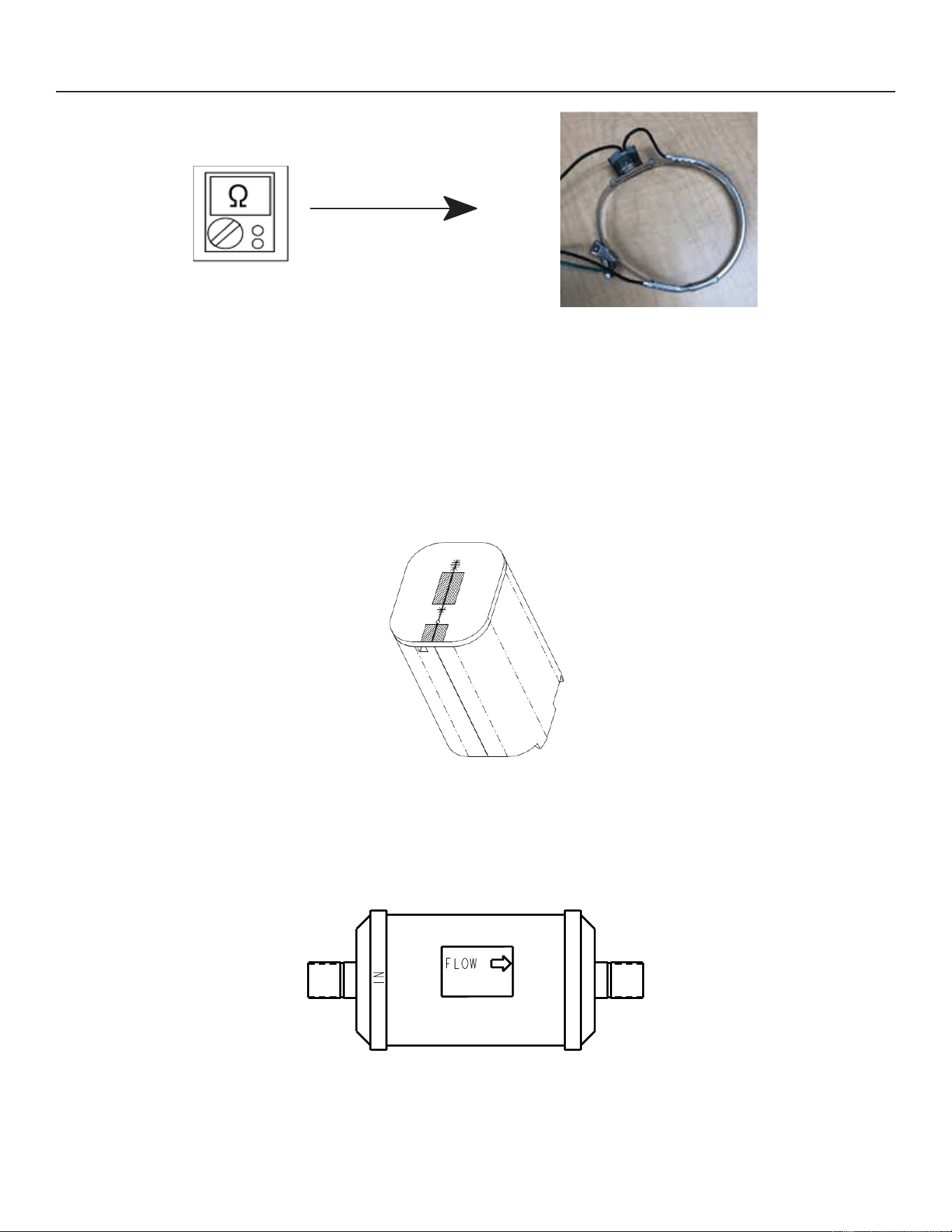
69
31-5000950 Rev. 0
Service Information
Figure 37. Checking Crankcase Heater Thermostat
STATUS CODE:
None
ERROR CODES:
None
Compressor Sound Cover
All units come with a soft-sided polyethylene molded outer shell compressor sound cover. The cover helps reduce any
unwanted operating sounds from the compressor. The cover features a hook/loop closure system for ease of installation
on the compressor.
Figure 38. Compressor Sound Cover
Suction Line Filter Drier
The NS19HXQLWVKDYHDURWDU\FRPSUHVVRUDQGKDYHDIDFWRU\LQVWDOOHGVXFWLRQOLQH¿OWHUGULHULQVWDOOHGLQWKHVXFWLRQOLQH
/LTXLGGULHULVQRWUHTXLUHGEXWPD\EH¿HOGLQVWDOOHG7KH¿OWHUGULHULVGHVLJQHGWRUHPRYHPRLVWXUHDQGIRUHLJQPDWWHU
which can lead to compressor failure.
Figure 39. Suction Line Filter Drier
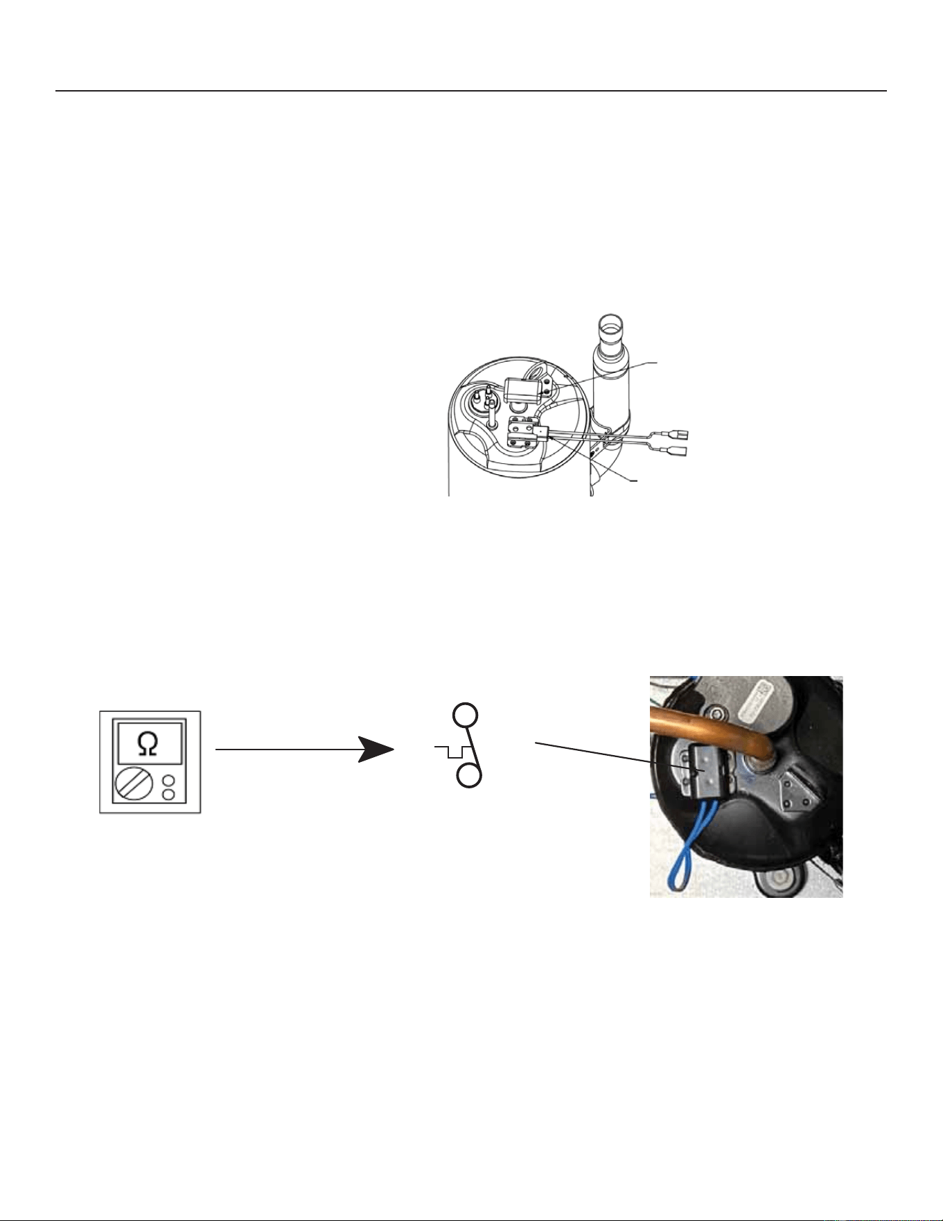
70
31-5000950 Rev. 0
Service Information
TOP CAP SWITCH OPERATION, CHECKOUT AND STATUS / ERROR CODES
OPERATION:
Top Cap Thermal Sensor Switch (S173)
Some units are equipped with a compressor-mounted normally closed temperature switch that prevents compressor damage
due to overheating caused by internal friction. The switch is located on top of the compressor casing. This switch senses the
FRPSUHVVRUFDVLQJWHPSHUDWXUHDQGRSHQVDW))WRVKXWRႇFRPSUHVVRURSHUDWLRQ7KHDXWRUHVHWVZLWFKFORVHV
ZKHQWKHFRPSUHVVRUFDVLQJWHPSHUDWXUHIDOOVWR))DQGWKHFRPSUHVVRULVUHHQHUJL]HG7KLVLVDVLQJOHSROH
single-throw (SPST) bi-metallic switch.
Compressor Top Cap Switch
6367%L0HWDOLF6ZLWFK
1RUPDOO\2SHQVDW))
$QG&ORVHV$W))
Sensor Cover
Thermal Switch
Figure 40. Top Cap Thermal Sensor Switch
CHECKOUT:
8VLQJDPXOWLPHWHUVHWWRRKPVZLWKWKHWHUPLQDOVGLVFRQQHFWHGIURPWKHV\VWHPFKHFNWKHUHVLVWDQFHEHWZHHQWKHWZR
WHUPLQDOVRIWKHWRSFDSVZLWFK,IWKHPHWHUGLVSOD\GRHVQRWFKDQJHWKHVZLWFKLVFORVHG,IWKHPHWHUGLVSOD\JRHVWR
LQ¿QLWHWKHVZLWFKLVRSHQ
S173
Compressor
Top Cap Switch
Figure 41. Verifying Top Cap Thermal Sensor Switch
STATUS:
None
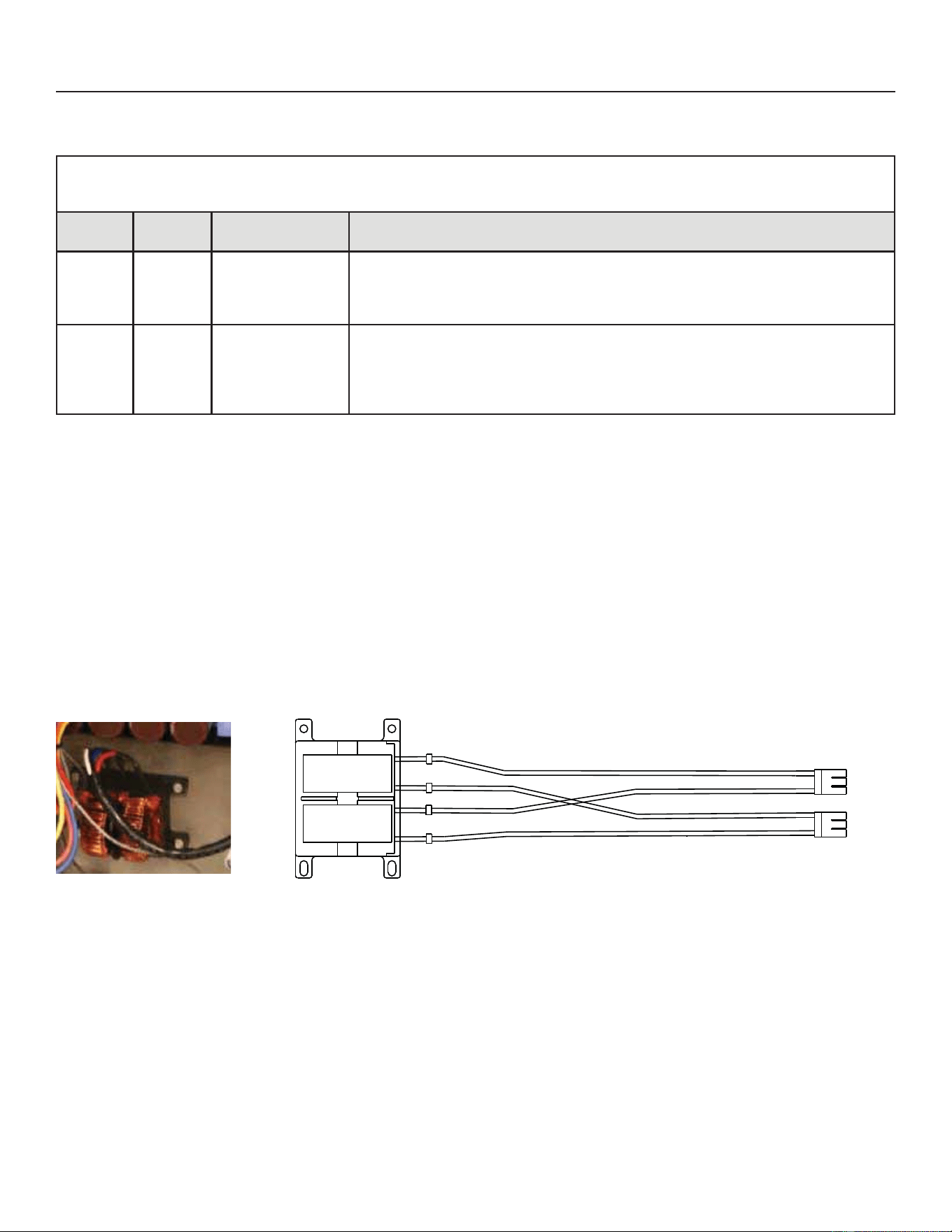
71
31-5000950 Rev. 0
Service Information
ERROR:
Table 14. Outdoor Control 7-Segment Display Alert Codes - Top Cap Switch
6\VWHPIDXOWDQGORFNRXWFRGHVWDNHSUHFHGHQFHRYHUV\VWHPVWDWXVFRGHVFRROLQJKHDWLQJRSHUDWLQJSHUFHQWDJHVRUGHIURVW
GHKXPLGL¿FDWLRQ2QO\WKHODWHVWDFWLYHIDXOWRUORFNRXWFRGHVDUHGLVSOD\HGLISUHVHQW,IQRIDXOWRUORFNRXWFRGHVDUHDFWLYHWKHQ
system status codes are displayed. Alert codes are also displayed on the communicating thermostat.
Alert
Codes
Priority Alarm Description Possible Causes and Clearing Alarm
E422 Moderate
Compressor
top cap switch
exceeding thermal
limit.
7KHWRSRIWKHFRPSUHVVRULVKRW5HIULJHUDQWFKDUJHPD\EHORZRUORZPDVVÀRZ
RIUHIULJHUDQW&KHFN7;9FORJJHG¿OWHUGULHUFRQGHQVHUIDQPRWRULQGRRUEORZHU
PRWRUFRQ¿UPLQGRRUFRLOLVFOHDQ&KHFNWRPDNHVXUHWKHEOXHZLUHVIURPWKHWRS
WKHUPRVWDWGLGQRWJHWSXOOHGRႇRQHRIWKH73WHUPLQDORQWKHRXWGRRUFRQWUROERDUG
E442 Critical
The top cap switch
has opened 5 times
within one hour. As
DUHVXOWWKHRXWGRRU
unit is locked out
:KHQFRPSUHVVRUWKHUPDOSURWHFWLRQVHQVRURSHQVWLPHVZLWKLQKRXURXWGRRU
stops working.
7RFOHDUGLVFRQQHFWSRZHUWRWKHLQGRRUXQLW9$&SRZHUVRXUFHWRWKHRXWGRRU
FRQWUROZKLFKZLOOSRZHURႇWKHRXWGRRUFRQWURODQGZLOORSHQWKHRXWGRRUXQLW
FRQWDFWRUZKLFKLQWHUUXSWVSRZHUWRWKHLQYHUWHUDQGWKHQUHDSSO\SRZHU
Reactor Operations, Checkout and Status / Error Codes
OPERATION:
5HDFWRU,QGXFWRURUFKRNHLVDSDVVLYHWZRWHUPLQDOHOHFWULFDOFRPSRQHQWWKDWVWRUHVHQHUJ\LQLWVPDJQHWLF¿HOG
5HDFWRUVDUHRQHRIWKHEDVLFFRPSRQHQWVXVHGLQHOHFWURQLFVZKHUHFXUUHQWDQGYROWDJHFKDQJHZLWKWLPHGXHWRWKH
ability of inductors to delay and reshape alternating currents.
CHECKOUT:
Main Power ON – Voltage IN reactor should be the same as the voltage OUT. With main power OFF and reactor
disconnected from system; resistance between leads should be the same.
STATUS CODES:
None
ERROR CODES:
None
92/7$*(,1
92/7$*(287
Figure 42. Reactor
Outdoor Fan Operation and Checkout
OPERATION:
The NS19H units have a variable speed ECM fan motor. The variable speed ECM fan motor is controlled by PWM fan
output when the compressor is running and will vary the fan speed to match the compressor capacity.
LOW AMBIENT OPERATION:
The NS19H units have factory installed low ambient operator that will control the condenser fan motor based upon liquid
line temperature.
The NS19H units have a variable speed ECM fan motor. The outdoor control will begin to modulate the outdoor fan motor
VSHHGLVEHORZ)WRPDLQWDLQDOLTXLGOLQHVHQVRUWHPSHUDWXUHEHWZHHQ)DQG),IWKHOLTXLGOLQHVHQVRUGURSV
EHORZ)WKHFRQWUROZLOOF\FOHWKHIDQRႇXQWLOOLTXLGWHPSHUDWXUHULVHVDERYH)
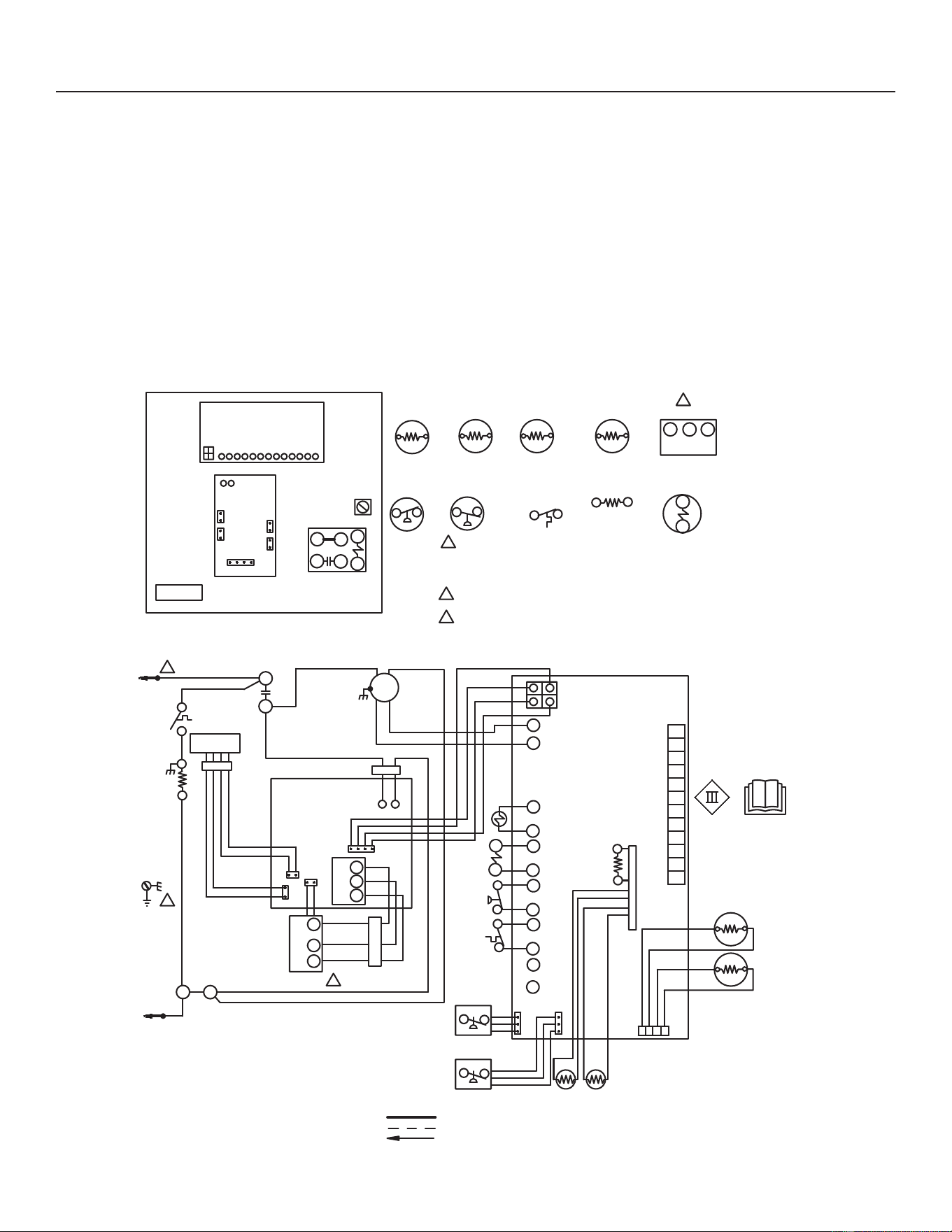
72
31-5000950 Rev. 0
Service Information
CHECKOUT:
VAC Voltage Check
Check for 208/240 VAC power at inverter contactor (red wires) (see Figure 42).
Units with ECM Motor:
:LWKWKHXQLWUXQQLQJFKHFNIRU9$&DWWKHUHGRXWGRRUIDQPRWRUZLUHVDWWKHFRQWDFWRU,IQRYROWDJHLVSUHVHQW
check main power at the contactor.
2. Perform a DC voltage check between the FPWM and Fan C terminal.
8VLQJWKHSXVKEXWWRQRQWKHFRQWUROHQWHUWKHFan Test Mode in the Field Test Mode by pushing and holding the
button until solid "–"DSSHDUVUHOHDVHWKHEXWWRQ'LVSOD\ZLOOVWDUWÀDVKLQJZLWKLQVHFRQGVSXVKDQGKROGWKH
button until the "F"V\PEROGLVSOD\VWKHQUHOHDVHWKHEXWWRQ'LVSOD\ZLOOEHJLQWRÀDVK"F"ZLWKLQVHFRQGVSXVK
DQGKROGWKHEXWWRQXQWLOLWVWRSVÀDVKLQJUHOHDVHWKHEXWWRQ2XWGRRUIDQPRWRUZLOOF\FOHRQIRUPLQXWHV7RH[LW
SXVKDQGKROGWKHEXWWRQXQWLOWKUHHKRUL]RQWDOEDUVGLVSOD\5HOHDVHWKHEXWWRQDQGWKHRXWGRRUIDQZLOOF\FOHRႇ
EQUIPMENT
GROUND
2
1
RT13
AMBIENT
SENSOR
S87 LOW
PRESSURE
SWITCH
U
V
W
B1
COMPRESSOR
S4 HIGH
PRESSURE
SWITCH
TP
HPS
LPS
LIQ
AMB
COIL
B4
FAN
K1-2
3
COMPRESSOR
CONTACTOR
S40
HR1
CRANKCASE
THERMOSTAT
CRANKCASE
HEATER
RT36
LIQUID
SENSOR
NOTE-
FOR USE WITH COPPER CONDUCTORS
ONLY. REFER TO UNIT RATING PLATE
FOR MINIMUM CIRCUIT AMPACITY AND
MAXIMUM OVERCURRENT PROTECTION SIZE
REFER TO COMPRESSOR IN UNIT FOR
ACTUAL TERMINAL ARRANGEMENT
COMPRESSOR
CONTACTOR
RED
L2
2
K1-1
RT13
WARNING-ELECTRIC SHOCK HAZARD
CAN CAUSE INJURY OR DEATH. UNIT
MUST BE GROUNDED IN ACCORDANCE
WITH NATIONAL AND LOCAL CODES
BLACK
BROWN
RED
3
REV
CNTCTR
FAN PWM
COM
K1
B
A
REACTOR
BLUE
BLUE
RED
YELLOW
FERRITE
BROWN
FERRITE
FERRITE
INVERTER
S4
S173
S173
COMPRESSOR
TOP CAP SWITCH
COMPRESSOR
2
U
V
W
BLUE
BROWN
CP(L)
CP(N)
U
V
W
BLUE
BROWN
COMM
BROWN
1
R7
RESISTOR
(10K)
RED
BLACK
YELLOW
WHITE
OUTDOOR
CONTROL
L1
4
3
2
1
RT_SUCTION
SENSOR
BLUE
BLUE
R7
RT41
A175
SUCT P
LOW
PRESSURE
TRANSDUCER
A168
1234
RT_LIQUID
SENSOR
RT36
SUCT/
LIQ T
LIQ P
PARK
COM
FAN PWM
GROUND
LUG
K1
COMPRESSOR
CONTACTOR
O OUT
CNTCTR
HI PS
TP
LO PS
INVERTER
REACTOR
O Out
CNCTR
HI PS
TP
LO PS
C
R
O
i
i
-
+
DS
Y2
W
Y1
L
TST
DF
RT21
DEFROST COIL
SENSOR
L1
REVERSING
VALVE
L1
RT21
RT41
SUCTION
SENSOR
HIGH
PRESSURE
TRANSDUCER
A188
WHITE
RED
NOTE-
IF ANY WIRE IN THIS APPLIANCE IS REPLACED,IT
MUST BE REPLACED WITH WIRE OF LIKE SIZE,
RATING, INSULATION THICKNESS, AND TERMINATION.
LINE VOLTAGE FIELD INSTALLED
CLASS II VOLTAGE FIELD WIRING
DENOTES OPTIONAL COMPONENTS
Figure 43. VAC Voltage Check
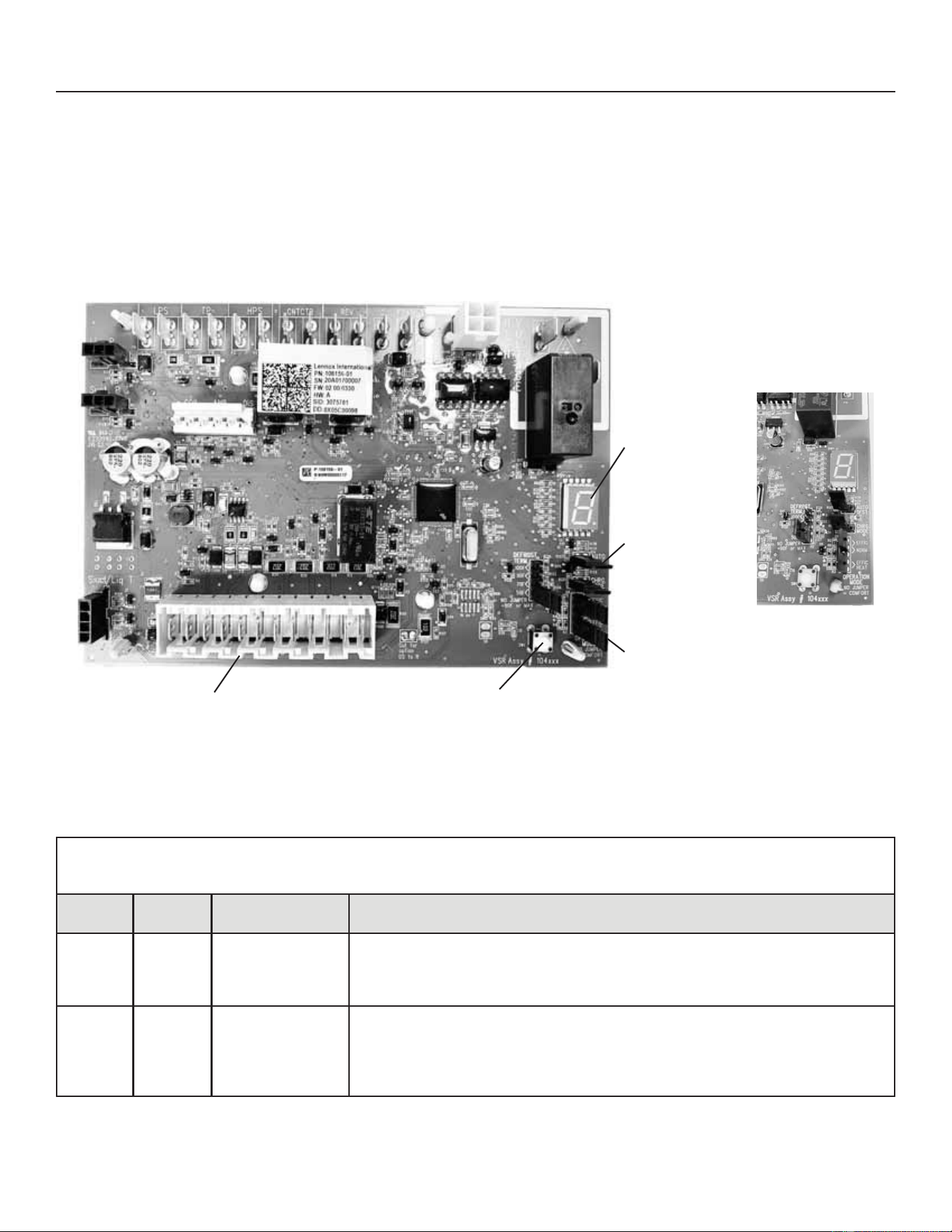
73
31-5000950 Rev. 0
Service Information
Outdoor Control Operation, Checkout and Status / Error Codes
OPERATION:
The outdoor control is a microprocessor-based device for use with variable-capacity compressors up to 5-tons in capacity
RSHUDWLQJRQ9$&UHVLGHQWLDOSRZHU7KHRXWGRRUFRQWUROLQWHJUDWHVWKHIXQFWLRQDOLW\RIPDLQWDLQLQJFRPSUHVVRUVSHHG
DQGRXWGRRUIDQFRQWURORI(&0PRWRUV7KHRXWGRRUFRQWUROLVVHOIFRQ¿JXULQJ'XULQJVWDUWXSWKHRXWGRRUFRQWUROVHOHFWV
RQHRIWZRFRQ¿JXUDWLRQVYDULDEOHFDSDFLW\DLUFRQGLWLRQHURUYDULDEOHFDSDFLW\KHDWSXPS
The NS19HRXWGRRUFRQWUROSURYLGHVDSSOLFDWLRQÀH[LELOLW\7KHNS19H may be installed with a conventional 24VAC non-
communicating single or two stage heat pump thermostat.
7-Segment Display
Charge Mode
-XPSHU&+5*
Mode)
Operation Mode
-XPSHU
Push Button
Rast Terminals for Thermostat Wiring Connection
Charge Mode and
Operation Mode
-XPSHU'HWDLO
Figure 44. Outdoor Control Unit
STATUS CODES:
Table 15. Outdoor Control 7-Segment Display Alert Codes - Outdoor Control Status
NOTE6\VWHPIDXOWDQGORFNRXWFRGHVWDNHSUHFHGHQFHRYHUV\VWHPVWDWXVFRGHVFRROLQJKHDWLQJRSHUDWLQJSHUFHQWDJHVRU
GHIURVWGHKXPLGL¿FDWLRQ2QO\WKHODWHVWDFWLYHIDXOWRUORFNRXWFRGHVDUHGLVSOD\HGLISUHVHQW,IQRIDXOWRUORFNRXWFRGHVDUHDFWLYH
then system status codes are displayed.
Alert
Codes
Priority Alarm Description Possible Causes and Clearing Alarm
E 600 Critical
Compressor has
been cycled OFF
on utility load
shedding
Load shedding function: Provides a method for a local utility company to limit the
maximum power level usage of the outdoor unit. The feature is activated by applying
24 volts AC power to the L and C terminals on the outdoor control.
E 601 Critical
Outdoor unit has
been cycled OFF
on low temperature
protection.
Low temperature Protection: Outdoor unit will not operate when the outdoor
WHPSHUDWXUHLVDWRUEHORZ)&,IWKHXQLWLVRSHUDWLQJDQGWKHRXWGRRU
WHPSHUDWXUHGURSVEHORZ)&WKHXQLWZLOOFRQWLQXHWRRSHUDWHXQWLOWKHURRP
WKHUPRVWDWLVVDWLV¿HGRUWKHRXWGRRUWHPSHUDWXUHGURSVWR)&2XWGRRUXQLW
ambient sensor provides temperature readings.)
74
31-5000950 Rev. 0
Service Information
6\VWHP&RQ¿JXUDWLRQ
Thermostat Control Options
The NS19H variable capacity units provide two thermostat
control options to provide application and installation
ÀH[LELOLW\
Conventional 24VAC Non-Communicating Heat Pump
Thermostat Control
The NS19H variable capacity unit may be installed using a
conventional 24VAC non-communicating two-stage cooling
or single-stage heat pump thermostat.
NOTE – The conventional 24VAC non-communicating
thermostat must have a compressor minimum on time of
three minutes to prevent compressor short cycling. The
0&RPIRUW6HQVH&RPIRUW6HQVHDQGPDQ\
other commercially available electronic thermostats provide
this feature.
The NS19H unit will provide full variable capacity
operation when installed with a conventional 24VAC
non-communicating two stage or single-stage heat pump
thermostat. The NS19H outdoor control has advanced
control algorithms using the NS19H suction pressure
sensor in the cooling mode and liquid pressure sensor
in the heating mode to provide true variable capacity
compressor operation.
When utilizing a two-stage conventional 24VAC non-
FRPPXQLFDWLQJKHDWSXPSWKHUPRVWDWVL[ZLUHVDUH
UHTXLUHGWRFRQWUROWKHRXWGRRUXQLW5&<<2
and W). Refer to the NS19H¿HOGZLULQJGLDJUDPIRUD
conventional 24VAC non-communicating 2-stage heat
pump thermostat.
Thermostat Type Indoor Unit Type
Qty. of Wires
to NS19H
NS19H Terminal Strip
Connections
Unit Operation
Field Wiring
Diagram
Conventional 24VAC
2-Stage Heat Pump
Thermostat (non-
communicating)
Any Furnace or
Air Handler (non-
communicating or
communicating)
6 5&<<2:
Full Variable Capacity Operation
Controlled by NS19H Unitary Control
Using Suction Pressure in Cooling Mode
and Liquid Pressure in Heating Mode
Figure 16
Cooling Operation Mode Jumper
7KH&RROLQJ2SHUDWLRQ0RGH-XPSHULVRQO\XVHGRQ
applications installed with a conventional 24VAC non-
communicating heat pump thermostat. In applications
with a conventional 24VAC non-communicating heat
SXPSWKHUPRVWDWWKHFRPSUHVVRUFDSDFLW\LVFRQWUROOHGWR
maintain the target suction pressure setpoint. The Cooling
2SHUDWLRQ0RGH-XPSHUKDVWKUHHVHOHFWDEOHFRROLQJ
PRGHV7KHWKUHHPRGHVDUH(ႈFLHQF\-XPSHULQVWDOOHG
RQ3LQVDQG1RUPDO0RGH-XPSHULQVWDOOHGRQ3LQV
DQGDQG&RPIRUW0RGH-XPSHU5HPRYHG7KHIDFWRU\
GHIDXOWSRVLWLRQLVWKH(ႈFLHQF\0RGH7KH(ႈFLHQF\
mode has a variable suction pressure setpoint that will vary
with the outdoor temperature; as the outdoor temperature
increases the suction pressure setpoint will decrease.
When the Cooling Operation Mode jumper is installed in
the “Normal Mode” the suction pressure setpoint is 135
psig.
When the Cooling Operation Mode jumper is installed in
the Comfort Mode the suction pressure setpoint is 125
psig.
Cooling Operation Mode Jumper (Conventional 24VAV
Thermostats Only)
Operation Mode
Jumper
Jumper Position Target Suction
Pressure Setting
(ႈFLHQF\GHIDXOW Pin 1 to Pin 2 Variable based on OAT
Normal Pin 2 to Pin 3 135 psig
Comfort -XPSHU2ႇ 125 psig
Heating Operation Mode Jumper
7KH+HDWLQJ2SHUDWLRQ0RGH-XPSHULVRQO\XVHGRQ
applications installed with a conventional 24VAC non-
communicating heat pump thermostat. In applications
with a conventional 24VAC non-communicating heat
SXPSWKHUPRVWDWWKHFRPSUHVVRUFDSDFLW\LVFRQWUROOHGWR
maintain the target liquid pressure setpoint. The Heating
2SHUDWLRQ0RGH-XPSHUKDVWZRVHOHFWDEOHKHDWLQJ
PRGHV7KHWZRPRGHVDUH(ႈFLHQF\-XPSHULQVWDOOHGRQ
3LQVDQGDQG&RPIRUW0RGH-XPSHU5HPRYHG7KH
IDFWRU\GHIDXOWSRVLWLRQLVWKH(ႈFLHQF\0RGH
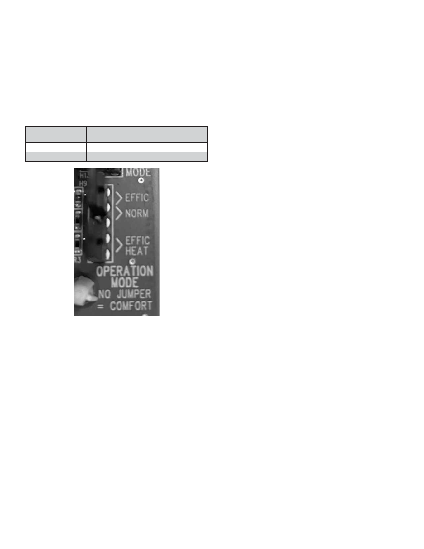
75
31-5000950 Rev. 0
Service Information
Heating Operation Mode Jumper (cont)
7KH(ႈFLHQF\PRGHKDVDYDULDEOHOLTXLGSUHVVXUHVHWSRLQW
that will vary with the outdoor temperature; as the outdoor
WHPSHUDWXUHGHFUHDVHVWKHOLTXLGSUHVVXUHVHWSRLQWZLOO
increase. When the Operation Mode jumper is installed in
the “Comfort Mode” the liquid pressure setpoint is 425 psig.
Heating Operation Mode Jumper (Conventional 24VAV
Thermostats Only)
Operation Mode
Jumper
Jumper Position Target Liquid Pressure
Setting
(ႈFLHQF\GHIDXOW Pin 4 to Pin 5 Variable based on OAT
Comfort -XPSHU2ႇ 425 psig
Figure 45. Operation Mode Jumper
Unit Operation
NS19H Unit Operation with a Conventional 24VAC
Non-Communicating 2-Stage Heat Pump Thermostat –
Cooling Mode
When the NS19H unit is installed with a conventional
9$&QRQFRPPXQLFDWLQJVWDJHKHDWSXPSWKHUPRVWDW
the O terminal on the thermostat will energize the unit
reversing valve to place the unit in the cooling mode. A Y1
¿UVWVWDJHFRROLQJGHPDQGZLOOLQLWLDWHFRROLQJRSHUDWLRQDQG
¿UVWVWDJHLQGRRUEORZHURSHUDWLRQ7KHFRPSUHVVRUZLOO
be controlled in the variable capacity mode by varying the
compressor capacity to obtain the target suction pressure
set point. The Y2 second stage cooling demand will initiate
second stage blower operation. Increased air volume
will increase the load on the indoor coil and increase the
suction pressure. The NS19H compressor capacity will
continue to be controlled based upon the suction pressure.
The unit capacity will be controlled in the variable capacity
mode throughout the range of capacity from minimum
capacity to maximum capacity. If the Y2 demand remains
DIWHUPLQXWHVWKHNS19H control will begin to ramp
up the compressor capacity until maximum capacity is
achieved. The NS19HXQLWZLOOF\FOHRႇRQFHWKHWKHUPRVWDW
GHPDQGLVVDWLV¿HG
NS19H Unit Operation with a Conventional 24VAC
Non-Communicating 2-Stage Heat Pump Thermostat -
Heating Mode
When the NS19H unit is installed with a conventional
9$&QRQFRPPXQLFDWLQJVWDJHKHDWSXPSWKHUPRVWDW
O terminal is not powered during the heating mode and
the reversing valve is de-energized placing hte unit in
WKHKHDWLQJPRGH$<¿UVWVWDJHFRPSUHVVRUGHPDQG
ZLOOLQLWLDWHFRPSUHVVRURSHUDWLRQDQG¿UVWVWDJHLQGRRU
blower operation. The compressor will be controlled in
the variable capacity mode by varying the compressor
capacity to obtain the target liquid pressure set point. The
Y2 second stage compressor demand will initiate second
stage blower operation. Increased air volume will increase
heat transfer on the indoor coil and degrease the liquid
pressure. if the liquid pressure drops below the target
VHWSRLQWWKHFRPSUHVVRUFDSDFLW\ZLOOEHLQFUHDVHG7KH
NS19H compressor capacity will continue to be controlled
based upon the liquid pressure. The unit capacity will be
controlled in the variable capacity mode throughout the
range of capacity from minimum capacity to maximum
FDSDFLW\,IWKH<GHPDQGUHPDLQVDIWHUPLQXWHV
the NS19H control will begin to ramp up the compressor
capacity until maximum capacity is achieved. The NS19H
XQLWZLOOF\FOHRႇRQFHWKHWKHUPRVWDWGHPDQGLVVDWLV¿HG
NS19H Unit Operation with a Conventional 24VAC Non-
Communicating Single-Stage Heat Pump Thermostat
– Cooling Mode
When the NS19H unit is installed with a conventional
24VAC non-communicating single-stage heat pump
WKHUPRVWDWWKH2WHUPLQDORQWKHWKHUPRVWDWZLOOHQHUJL]H
the unit reversing valve to place the unit in the cooling
PRGH$<¿UVWVWDJHFRROLQJGHPDQGZLOOLQLWLDWHFRROLQJ
operation and cooling indoor blower operation. In single
VWDJHWKHUPRVWDWDSSOLFDWLRQVDMXPSHUPXVWEHLQVWDOOHG
between Y1 and Y2 on the NS19H outdoor control. The
compressor will be controlled in the variable capacity mode
by varying the compressor capacity to obtain the target
suction pressure set point. If the cooling demand remains
DIWHUPLQXWHVWKHNS19H control will begin to ramp
up the compressor capacity until maximum capacity is
achieved. The NS19HXQLWZLOOF\FOHRႇRQFHWKHWKHUPRVWDW
GHPDQGLVVDWLV¿HG
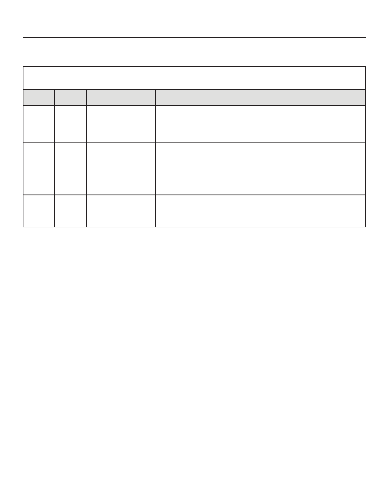
76
31-5000950 Rev. 0
Service Information
ERROR CODES:
Table 16. Outdoor Control 7-Segment Display Alert Codes - Outdoor Control Errors
NOTE - 6\VWHPIDXOWDQGORFNRXWFRGHVWDNHSUHFHGHQFHRYHUV\VWHPVWDWXVFRGHVFRROLQJKHDWLQJRSHUDWLQJSHUFHQWDJHVRU
GHIURVWGHKXPLGL¿FDWLRQ2QO\WKHODWHVWDFWLYHIDXOWRUORFNRXWFRGHVDUHGLVSOD\HGLISUHVHQW,IQRIDXOWRUORFNRXWFRGHVDUHDFWLYH
then system status codes are displayed.
Alert
Codes
Priority Alarm Description Possible Causes and Clearing Alarm
E 105 Moderate
The outdoor control has
lost communication with
either the thermostat or
indoor unit.
Equipment is unable to communicate. Indicates numerous message errors. In
most cases errors are related to electrical noise. Make sure high voltage power
is separated from RSBus. Check for miswired and/or loose connections between
WKHVWDWLQGRRUXQLWDQGRXWGRRUXQLW&KHFNIRUDKLJKYROWDJHVRXUFHRIQRLVH
close to the system. Fault clears after communication is restored.
E 120 Moderate
There is a delay in the
outdoor unit responding
to the system.
7\SLFDOO\WKLVDODUPFRGHGRHVQRWFDXVHDQ\LVVXHVDQGZLOOFOHDURQLWVRZQ
The alarm / code is usually caused by a delay in the outdoor unit responding to
the thermostat. Check all wiring connections. Cleared after unresponsive device
responds to any inquiry.
E 125 Critical
There is a hardware
problem with the outdoor
control.
There is a control hardware problem. Replace the outdoor control if the problem
prevents operation and is persistent. The alarm / fault is cleared 300 seconds
after the fault recovers.
E 131 Critical
The outdoor unit
control parameters are
corrupted
5HFRQ¿JXUHWKHV\VWHP5HSODFHWKHFRQWUROLIKHDWLQJRUFRROLQJLVQRWDYDLODEOH
E 132 Critical Internal software error Replace outdoor control.
UNIT SENSOR OPERATION, CHECKOUT AND STATUS /ERROR CODES
OPERATION:
6-Pin Sensor Harness (DIS, AMB, COIL)
• Discharge Sensor (R7 - No Sensor) - There is no sensor located on positions 5 and 6 of the connector. A 10K Ohm
resistor installed between pins 5 and 6 on the cable harness provides continuity for this circuit.
• Ambient Temperature Sensor (RT13) - $PELHQWWHPSHUDWXUHVDVUHDGE\WKHDPELHQWWHPSHUDWXUHVHQVRUFRQQHFWHG
WRSLQDQGSLQZKLFKDUHEHORZ)&RUDERYH)&WULJJHUDIDXOWFRQGLWLRQ,IWKHDPELHQWVHQVRULV
RSHQVKRUWHGRURXWRIWKHWHPSHUDWXUHUDQJHRIWKHVHQVRUWKHFRQWUROGLVSOD\VWKHDSSURSULDWHDOHUWFRGH+HDWLQJDQG
cooling operation is allowed in this fault condition.
• Coil Temperature Sensor (RT21) - The liquid temperature sensor located on the outlet of the outdoor TXV is connected
to pins 5 and 6.
4-Pin Suction Temperature Sensor / Liquid Temperature Sensor Harness
• Suction Line Sensor (RT41) - Suction line temperature is read by the suction line temperature sensor between Pins 1
and Pin 2 of the 4-pin sensor harness. Nominal Resistance of the sensor is 10K ohms at 77ºF. The control will display
are E182 error code if the sensor reads open or shorted for 24 hours. Cooling operation is allowed with this fault.
• Liquid Line Temperature Sensor (RT36) - Liquid line temperature is read by the liquid line temperature sensor
between Pins 3 and Pin 4 of the 4-pin sensor harness. Nominal Resistance of the sensor is 10K ohms at 77ºF. The
control will display are E184 error code if the sensor reads open or shorted for 24 hours. Cooling operation is allowed
with this fault.
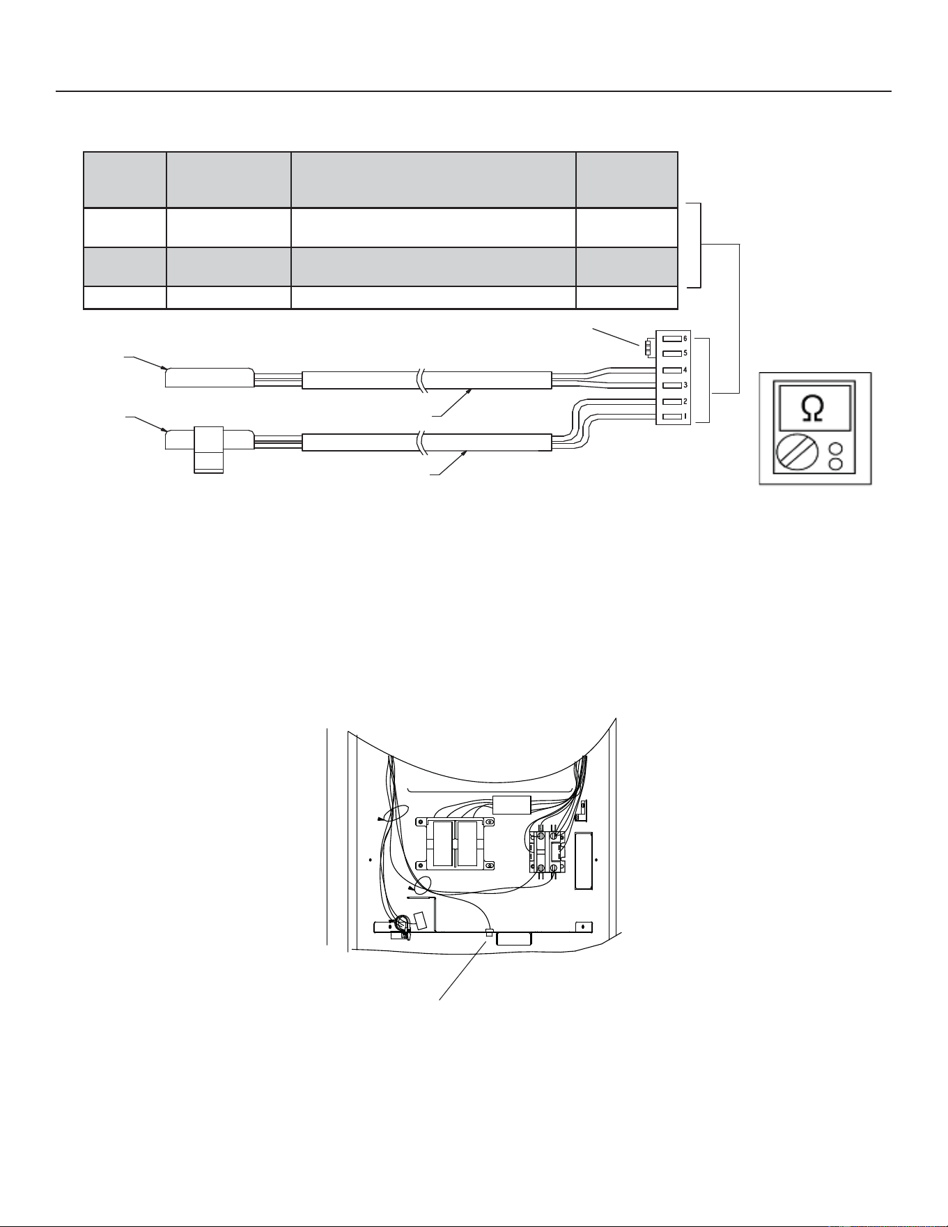
77
31-5000950 Rev. 0
Service Information
UNIT SENSOR OPERATION, CHECKOUT AND STATUS /ERROR CODES (cont)
Sensor
Temp Range ºF
(ºC)
Resistance Values Range (Ohms)
Pin# / Wire
Sleeve Color
Coil
-40ºF (-40ºC) to
140ºF (60ºC)
WRVHHTable 17 for exact
temperature to ohm readings)
6 and 5
(BROWN)
Outdoor
Ambient
-40ºF (-40ºC) to
140ºF (60ºC)
WRVHHTable 17 for exact
temperature to ohm readings)
4 and 3
(BLACK)
Discharge N/A N/A 2 and 1
Outdoor
Ambient
Liquid
Line
10K Ohm Resistor
Temperature
Sensor Harness
Black Wires with
BLACK Sleeve
Black Wires with
BROWN Sleeve
Figure 46. 7HPSHUDWXUH6HQVRU6SHFL¿FDWLRQ
CHECKOUT:
6HQVRUVFRQQHFWWRWKHRXWGRRUFRQWUROWKURXJKD¿HOGUHSODFHDEOHKDUQHVVDVVHPEO\WKDWSOXJVLQWRWKHRXWGRRUFRQWURO
7KURXJKWKHVHQVRUVWKHFRQWUROGHWHFWVRXWGRRUDPELHQWFRLODQGOLTXLGWHPSHUDWXUHIDXOWFRQGLWLRQV$VWKHGHWHFWHG
WHPSHUDWXUHFKDQJHVWKHUHVLVWDQFHDFURVVWKHVHQVRUFKDQJHV&KHFNVHQVRURSHUDWLRQE\UHDGLQJRKPVDFURVVSLQV
VKRZQLQ¿JXUH
NOTE±:KHQFKHFNLQJWKHRKPVDFURVVDVHQVRUEHDZDUHWKDWDVHQVRUVKRZLQJDUHVLVWDQFHYDOXHWKDWLVQRWZLWKLQ
WKHH[SHFWHGUDQJHPD\EHSHUIRUPLQJDVGHVLJQHG+RZHYHULIDVKRUWHGRURSHQFLUFXLWLVGHWHFWHGWKHQWKHVHQVRU
may be faulty and the sensor harness will need to be replaced.
Outdoor Ambient
Temperature Sensor
Figure 47. Temperature Sensor Location
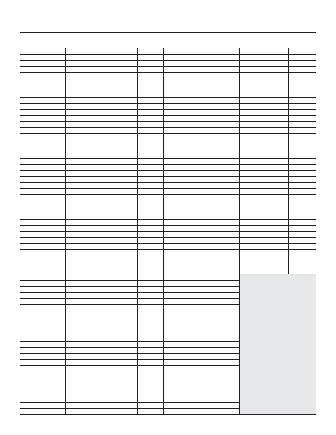
78
31-5000950 Rev. 0
Service Information
Table 17. Ambient and Liquid Line Sensors Temperature / Resistance Range
Degrees Fahrenheit ºF Resistance Degrees Fahrenheit ºF Resistance Degrees Fahrenheit ºF Resistance Degrees Fahrenheit ºF Resistance
136.3 2680 56.8 16657 21.6 44154 -11.3 123152
133.1 2859 56.0 16973 21.0 44851 -11.9 125787
130.1 3040 55.3 17293 20.5 45560 -12.6 128508
127.3 3223 54.6 17616 20.0 46281 -13.2 131320
124.7 3407 53.9 17942 19.4 47014 -13.9 134227
122.1 3592 53.2 18273 18.9 47759 -14.5 137234
119.7 3779 52.5 18607 18.4 48517 -15.2 140347
117.5 3968 51.9 18945 17.8 49289 -15.9 143571
115.3 4159 51.2 19287 17.3 50074 -16.5 146913
113.2 4351 50.5 19633 16.8 50873 -17.2 150378
111.2 4544 49.9 19982 16.3 51686 -17.9 153974
109.3 4740 49.2 20336 15.7 52514 -18.6 157708
107.4 4937 48.5 20695 15.2 53356 -19.3 161588
105.6 5136 47.9 21057 14.7 54215 -20.1 165624
103.9 5336 47.3 21424 14.1 55089 -20.8 169824
102.3 5539 46.6 21795
13.6 55979 -21.5 174200
100.6 5743 46.0 22171 13.1 56887 -22.3 178762
99.1 5949 45.4 22551 12.5 57811 -23.0 183522
97.6 6157 44.7 22936 12.0 58754 -23.8 188493
96.1 6367 44.1 23326 11.5 59715 -24.6 193691
94.7 6578 43.5 23720 11.0 60694 -25.4 199130
93.3 6792 42.9 24120 10.4 61693 -26.2 204829
92.0 7007 42.3 24525 9.9 62712 -27.0 210805
90.6 7225 41.7 24934 9.3 63752 -27.8 217080
89.4 7444 41.1 25349 8.8 64812 -28.7 223677
88.1 7666 40.5 25769 8.3 65895 -29.5 230621
86.9 7890 39.9 26195 7.7 67000 -30.4 237941
85.7 8115 39.3 26626 7.2 68128 -31.3 245667
84.5 8343 38.7 27063 6.7 69281 -32.2 253834
83.4 8573 38.1 27505 6.1 70458 -33.2 262482
82.3 8806 37.5 27954 5.6 71661 -34.1 271655
81.2 9040 37.0 28408 5.0 72890 -35.1 281400
80.1 9277
36.4 28868 4.5 74147 -36.1 291774
79.0 9516 35.8 29335 3.9 75431 -37.1 302840
78.0 9757 35.2 29808 3.4 76745 -38.2 314669
77.0 10001 34.7 30288 2.8 78090 -39.2 327343
76.0 10247 34.1 30774 2.3 79465
75.0 10496 33.5 31267 1.7 80873
74.1 10747 33.0 31766 1.2 82314
73.1 11000 32.4 32273 0.6 83790
72.2 11256 31.9 32787 0.0 85302
71.3 11515 31.3 33309 -0.5 86852
70.4 11776 30.7 33837 -1.1 88440
69.5 12040 30.2 34374 -1.7 90068
68.6 12306 29.6 34918 -2.2 91738
67.7 12575 29.1 35471 -2.8 93452
66.9 12847 28.6 36031 -3.4 95211
66.0 13122 28.0 36600 -4.0 97016
65.2 13400 27.5 37177 -4.6 98870
64.4 13681 26.9 37764 -5.2 100775
63.6 13964 26.4 38359 -5.7 102733
62.8 14251 25.8 38963 -6.3 104746
62.0 14540 25.3 39577 -6.9 106817
61.2 14833
24.8 40200 -7.5 108948
60.5 15129 24.2 40833 -8.2 111141
59.7 15428 23.7 41476 -8.8 113400
59.0 15730 23.2 42130 -9.4 115727
58.2 16036 22.6 42794 -10.0 118126
57.5 16345 22.1 43468 -10.6 120600
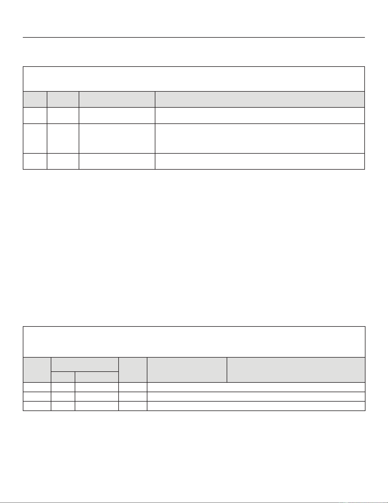
79
31-5000950 Rev. 0
Service Information
ERROR CODES:
Table 18. Outdoor Control 7-Segment Display Alert Codes - Outdoor Control Errors
NOTE - 6\VWHPIDXOWDQGORFNRXWFRGHVWDNHSUHFHGHQFHRYHUV\VWHPVWDWXVFRGHVFRROLQJKHDWLQJRSHUDWLQJSHUFHQWDJHVRU
GHIURVWGHKXPLGL¿FDWLRQ2QO\WKHODWHVWDFWLYHIDXOWRUORFNRXWFRGHVDUHGLVSOD\HGLISUHVHQW,IQRIDXOWRUORFNRXWFRGHVDUHDFWLYH
then system status codes are displayed.
Alert
Codes
Priority Alarm Description Possible Causes and Clearing Alarm
E 182 Moderate
Suction Temperature
Sensor has malfunctioned
Sensor is open or shorted. Replace the sensor.
E 183 Moderate
Liquid Pressure Transducer
Fault
Liquid pressure transducer is out of range. The signal should be between 0.5
VDC and 4.5 VDC between Blue and Black. The error code will be cleared when
the proper signal is provided. Systems controlled by a conventional 24VAC heat
pump thermostat will operate in stage mode.
E 184 Moderate
Faulty outdoor liquid line
sensor
Sensor is open or shorted. Replace the sensor.
DC INVERTER CONTROL OPERATION, CHECKOUT, STATUS / ERROR CODES
OPERATION OF COMPONENTS:
(OHFWURPDJQHWLFFRPSDWLELOLW\FLUFXLW(0&(0&HQVXUHVWKHFRUUHFWRSHUDWLRQRIGLႇHUHQWHTXLSPHQWLWHPVZKLFKXVHRU
UHVSRQGWRHOHFWURPDJQHWLFSKHQRPHQD,WDOVRKHOSVWRQHJDWHWKHHႇHFWVRILQWHUIHUHQFH
CONVERTER:
Converts AC (alternating current) to DC (direct current).
POWER FACTOR CORRECTION (PFC) CIRCUIT:
7KH3)&PRGXOHLVDQLQWHJUDWHGSDUWRIWKHRXWGRRULQYHUWHUWKDWPRQLWRUVWKH'&EXVIRUKLJKORZDQGDEQRUPDOYROWDJH
FRQGLWLRQV,IDQ\RIWKHVHFRQGLWLRQVDUHGHWHFWHGWKH3)&IXQFWLRQDQGFRPSUHVVRUZLOOVWRS
INTELLIGENT (INVERTER) POWER MODULE (IPM):
The IPM converts DC power into AC power. The control method is known as pulse width modulation (PWM). This
PHDQVWKH'&LVVZLWFKHGRQDQGRႇYHU\TXLFNO\FKRSSHGE\WKHWUDQVLVWRUVZLWFKHVWRPDNHVLPXODWHG$&DWUHTXLUHG
frequency and voltage.
COMMUNICATION CONTROL CIRCUIT:
Receives and sends message between the inverter and the outdoor control.
STATUS CODES:
Table 19. Outdoor Control 7-Segment Display Alert Codes and Inverter LED Flash Codes
NOTE6\VWHPIDXOWDQGORFNRXWFRGHVWDNHSUHFHGHQFHRYHUV\VWHPVWDWXVFRGHVFRROLQJKHDWLQJRSHUDWLQJSHUFHQWDJHVRU
defrost/dehumidification). Only the latest active fault or lockout codes are displayed (if present). If no fault or lockout codes are
DFWLYHWKHQV\VWHPVWDWXVFRGHVDUHGLVSOD\HG
Alert Code
Inverter LED Flash Code
QXPEHURIÀDVKHV
Priority
Condition
Alarm Description Possible Causes and Clearing Alarm
Red LED Green LED
N/A
ON OFF
N/A -036 only: Indicates inverter is operating normally.
N/A
ON ON
N/A
-060 only: Indicates inverter is operating normally
N/A
OFF OFF
N/A
Indicates inverter is NOT energized.
80
31-5000950 Rev. 0
Service Information
Table 20. Outdoor Control 7-Segment Display Alert Codes and Inverter LED Flash Codes
NOTE6\VWHPIDXOWDQGORFNRXWFRGHVWDNHSUHFHGHQFHRYHUV\VWHPVWDWXVFRGHVFRROLQJKHDWLQJRSHUDWLQJSHUFHQWDJHVRUGHIURVWGHKXPLGLILFDWLRQ2QO\WKH
ODWHVWDFWLYHIDXOWRUORFNRXWFRGHVDUHGLVSOD\HGLISUHVHQW,IQRIDXOWRUORFNRXWFRGHVDUHDFWLYHWKHQV\VWHPVWDWXVFRGHVDUHGLVSOD\HG
Alert
Code
Inverter
Code
Inverter Flash
Code
Priority Alarm Description Possible Causes and Clearing Alarm
Red LED
Green
LED
E 423 40 ÀDVKHV
OFF
Moderate /
Critical
The inverter has
detected a circuit
problem.
Control will lock out after 10 strikes within an hour.
7RFOHDUGLVFRQQHFWSRZHUWRWKHLQGRRUXQLW9$&SRZHUVRXUFHWRWKHRXWGRRU
FRQWUROZKLFKZLOOSRZHURႇWKHRXWGRRUFRQWURODQGZLOORSHQWKHRXWGRRUXQLW
FRQWDFWRUZKLFKLQWHUUXSWVSRZHUWRWKHLQYHUWHUDQGWKHQUHDSSO\SRZHU
E 427 21 ÀDVKHV ÀDVK
Moderate /
Critical
The inverter has
detected a DC peak
fault condition.
,IFRQGLWLRQ$RUKLJKHULVGHWHFWHGRXWGRRUXQLWZLOOVWRSFRPSUHVVRUDQGIDQ
Antishort cycle is initiated. If peak current (55A or higher) occurs 10 times within an
KRXUV\VWHPZLOOORFNRXW
,QGLFDWHVKLJKSUHVVXUHFRQGHQVHUIDQIDLOXUHORFNHGFRPSUHVVRUURWRURURYHUFKDUJH
7RFOHDUGLVFRQQHFWSRZHUWRWKHLQGRRUXQLW9$&SRZHUVRXUFHWRWKHRXWGRRU
FRQWUROZKLFKZLOOSRZHURႇWKHRXWGRRUFRQWURODQGZLOORSHQWKHRXWGRRUXQLW
FRQWDFWRUZKLFKLQWHUUXSWVSRZHUWRWKHLQYHUWHUDQGWKHQUHDSSO\SRZHU
E 428 22 ÀDVKHV
2
ÀDVKHV
Moderate /
Critical
The inverter has
detected a high main
input current condition
,IFRQGLWLRQLVGHWHFWHGRXWGRRUXQLWZLOOVWRSFRPSUHVVRUDQGIDQ$QWLVKRUWF\FOHLV
LQLWLDWHG,IFRQGLWLRQRFFXUVWLPHVZLWKLQDQKRXUV\VWHPZLOOORFNRXW
,QGLFDWHVKLJKSUHVVXUHFRQGHQVHUIDQIDLOXUHRURYHUFKDUJH7RFOHDUGLVFRQQHFW
power to the indoor unit (24VAC power source to the outdoor control) which will power
RႇWKHRXWGRRUFRQWURODQGZLOORSHQWKHRXWGRRUXQLWFRQWDFWRUZKLFKLQWHUUXSWVSRZHU
to the inverter and then re-apply power.
E 429 23 ÀDVKHV
3
ÀDVKHV
Moderate /
Critical
On a call for compressor
RSHUDWLRQLI'&OLQN
power in inverter does
not rise above 180 VDC
IRUDQGWRQPRGHOV
250 VDC for 4 and 5
WRQPRGHOVZLWKLQ
VHFRQGVWKHFRQWURO
will display a moderate
code. If condition is
GHWHFWHGRXWGRRUXQLW
will stop (Compressor
and fan). Antishort
cycles is initiated. If
condition occurs 10
times within a 60 minute
UROOLQJWLPHSHULRG
system will lock out and
display a critical code.
Issues:
,I'&OLQNSRZHULQLQYHUWHUGRHVQRWULVHDERYH9'&IRUDQGWRQPRGHOV
9'&IRUDQGWRQPRGHOVZLWKLQVHFRQGVWKHRXWGRRUFRQWUROZLOO
display a moderate code.
(2) Capacitors on inverter do not properly charge.
Corrective Actions:
(1) Check for proper main power to outdoor unit and for any loose electrical
connections.
E 430 26 ÀDVKHV
6
ÀDVKHV
Moderate /
Critical
Compressor Startup Fail
,IFRQGLWLRQLVGHWHFWHGRXWGRRUXQLWZLOOVWRSFRPSUHVVRUDQGIDQ$QWLVKRUWF\FOHLV
LQLWLDWHG,IFRQGLWLRQRFFXUVWLPHVZLWKLQDQKRXUV\VWHPZLOOORFNRXW
,QGLFDWHVSRRUFRQQHFWLRQDWFRPSUHVVRUKDUQHVVLPSURSHUZLQGLQJUHVLVWDQFHORFNHG
FRPSUHVVRUURWRURUÀRRGHGFRPSUHVVRU
7RFOHDUGLVFRQQHFWSRZHUWRWKHLQGRRUXQLW9$&SRZHUVRXUFHWRWKHRXWGRRU
FRQWUROZKLFKZLOOSRZHURႇWKHRXWGRRUFRQWURODQGZLOORSHQWKHRXWGRRUXQLW
FRQWDFWRUZKLFKLQWHUUXSWVSRZHUWRWKHLQYHUWHUDQGWKHQUHDSSO\SRZHU
E 431 27 ÀDVKHV
7
ÀDVKHV
Moderate /
Critical
Error occurs when
PFC detects an over-
current condition of
$WKHFRQWUROZLOO
display a moderate
code. If condition is
GHWHFWHGRXWGRRUXQLW
will stop (Compressor
and fan). Anti-short
cycle is initiated.
Inverter is unavailable
to communicate with
the outdoor control for
3 minutes. If condition
occurs 10 times within
a 60 minute rolling time
SHULRGV\VWHPZLOOORFN
out and display a critical
code.
Issues:
,QGLFDWHVSRZHULQWHUUXSWLRQEURZQRXWSRRUHOHFWULFDOFRQQHFWLRQRUORRVHLQYHUWHU
input wire.
(2) System testing was set up and code was generated when the reversing valve is
de-energized coming out of defrost (code appears with or without 30 compressor
delay).
Corrective Actions:
(1) Check for proper main power to outdoor unit and for any loose electrical
connections.
81
31-5000950 Rev. 0
Service Information
Table 20. Outdoor Control 7-Segment Display Alert Codes and Inverter LED Flash Codes
NOTE6\VWHPIDXOWDQGORFNRXWFRGHVWDNHSUHFHGHQFHRYHUV\VWHPVWDWXVFRGHVFRROLQJKHDWLQJRSHUDWLQJSHUFHQWDJHVRUGHIURVWGHKXPLGLILFDWLRQ2QO\WKH
ODWHVWDFWLYHIDXOWRUORFNRXWFRGHVDUHGLVSOD\HGLISUHVHQW,IQRIDXOWRUORFNRXWFRGHVDUHDFWLYHWKHQV\VWHPVWDWXVFRGHVDUHGLVSOD\HG
Alert
Code
Inverter
Code
Inverter Flash
Code
Priority Alarm Description Possible Causes and Clearing Alarm
Red LED
Green
LED
E 432 28 ÀDVKHV
8
ÀDVKHV
Moderate /
Critical
The inverter has
detected a DC link high
voltage condition.
Error occurs when the DC link capacitor voltage is greater than 480VDC. If condition
LVGHWHFWHGRXWGRRUXQLWZLOOVWRSFRPSUHVVRUDQGIDQ$QWLVKRUWF\FOHLVLQLWLDWHG
,IFRQGLWLRQRFFXUVWLPHVZLWKLQDQKRXUV\VWHPZLOOORFNRXW6\VWHPZLOOVWRS7R
FOHDUGLVFRQQHFWSRZHUWRWKHLQGRRUXQLW9$&SRZHUVRXUFHWRWKHRXWGRRUFRQWURO
ZKLFKZLOOSRZHURႇWKHRXWGRRUFRQWURODQGZLOORSHQWKHRXWGRRUXQLWFRQWDFWRUZKLFK
interrupts power to the inverter and then re-apply power.
E 433 29 ÀDVKHV
9
ÀDVKHV
Moderate /
Critical
The inverter has
detected a compressor
over-current condition
Error occurs when compressor peak phase current is greater than 28A. Inverter will
LVVXHFRGH¿UVWDQGVORZGRZQWRWU\WRUHGXFHWKHFXUUHQW,IWKHFXUUHQWUHPDLQV
KLJKRXWGRRUXQLWZLOOVWRSFRPSUHVVRUDQGIDQ
$QWLVKRUWF\FOHLVLQLWLDWHG,IFRQGLWLRQRFFXUVWLPHVZLWKLQDQKRXUV\VWHPZLOO
ORFNRXW7RFOHDUGLVFRQQHFWSRZHUWRWKHLQGRRUXQLW9$&SRZHUVRXUFHWRWKH
RXWGRRUFRQWUROZKLFKZLOOSRZHURႇWKHRXWGRRUFRQWURODQGZLOORSHQWKHRXWGRRUXQLW
FRQWDFWRUZKLFKLQWHUUXSWVSRZHUWRWKHLQYHUWHUDQGWKHQUHDSSO\SRZHU
E 434 53 ÀDVKHV
3
ÀDVKHV
Moderate /
Critical
Outdoor control has lost
communications with
the inverter for greater
than 3 minutes.
Outdoor unit will stop all
compressor demand.
Outdoor control will
attempt to establish
communication
multiple times and
will automatically
clear when the error
clears. Unit will lock
out after 60 minutes if
communication is not
established and will
display a critical error
code.
Issues:
2XWGRRUGLVFRQQHFWLVRႇRURXWGRRUSRZHULVRႇZKHQLQGRRUSRZHULVRQVRXUFH
for 24VAC)
(2) Loose electrical power connections
(3) Interruption of main power to the inverter
*HQHUDWRUSRZHUVLQGRRUXQLWEXWQRWWKHRXWGRRUXQLW
Corrective Actions:
7RUHVHWF\FOHWKHLQGRRUSRZHURႇVRXUFHRI9$&WRRXWGRRUXQLWDQGEDFNRQ
This will de-energize outdoor control and inverter by cycling the contactor.
(2) Make sure the disconnect is on
(3) Check electrical power supply connections
(4) Check for proper main 230V power supply
E 435 60 ÀDVKHV OFF
Moderate /
Critical
Inverter internal error.
:KHQWKLVHUURURFFXUVWKHRXWGRRUFRQWUROZLOOF\FOHSRZHUWRWKHLQYHUWHUE\RSHQLQJ
the contactor for 2 minutes. Check that the EEPROM is properly seated.
$IWHUSRZHULVF\FOHGWRWKHLQYHUWHUWLPHVWKHRXWGRRUXQLWLVORFNHGRXW
E 436 62 ÀDVKHV
2
ÀDVKHV
Moderate /
Critical
Inverter heat sink
temperature exceeded
limit. Occurs when the
heat sink temperature
exceeds the inverter
limit. Inverter issues
FRGH¿UVWWKHQ
slows down to allow
the heat sink to cool. If
temperature remains
KLJKRXWGRRUXQLW
stops (compressor and
fan). Anti-short cycle
is initiated. If condition
occurs 5 times within an
KRXUV\VWHPLVORFNHG
out.
7RFOHDUGLVFRQQHFW
power to the indoor unit
(24VAC power source
to the outdoor control)
ZKLFKZLOOSRZHURႇWKH
outdoor control and
will open the outdoor
XQLWFRQWDFWRUZKLFK
interrupts power to
the inverter and then
reapply power.
Issue:
Feedback from supplier tear down of inverter indicates that the screws that hold the
inverter to the inverter board were loose causing poor contact between these two
components.
Corrective Action:
Tighten screws that hold the heat sink to the inverter control board.
NOTE:DLW¿YHPLQXWHVWRDOOFDSDFLWRUWRGLVFKDUJHEHIRUHFKHFNLQJVFUHZV
82
31-5000950 Rev. 0
Service Information
Table 20. Outdoor Control 7-Segment Display Alert Codes and Inverter LED Flash Codes
NOTE6\VWHPIDXOWDQGORFNRXWFRGHVWDNHSUHFHGHQFHRYHUV\VWHPVWDWXVFRGHVFRROLQJKHDWLQJRSHUDWLQJSHUFHQWDJHVRUGHIURVWGHKXPLGLILFDWLRQ2QO\WKH
ODWHVWDFWLYHIDXOWRUORFNRXWFRGHVDUHGLVSOD\HGLISUHVHQW,IQRIDXOWRUORFNRXWFRGHVDUHDFWLYHWKHQV\VWHPVWDWXVFRGHVDUHGLVSOD\HG
Alert
Code
Inverter
Code
Inverter Flash
Code
Priority Alarm Description Possible Causes and Clearing Alarm
Red LED
Green
LED
E 437 65 ÀDVKHV
5
ÀDVKHV
Moderate /
Critical
Heat sink temperature
sensor fault has
occurred (temperature
less than 4ºF or greater
than 264ºF after 10
minutes of operation).
This occurs when the temperature sensor detects a temperature less than 0.4ºF or
JUHDWHUWKDQ)DIWHUPLQXWHVRIRSHUDWLRQ,IFRQGLWLRQLVGHWHFWHGRXWGRRUXQLW
will stop (compressor and fan). Antishort cycle is initiated. If condition occurs 5 times
ZLWKLQDQKRXUV\VWHPZLOOORFNRXW
7RFOHDUGLVFRQQHFWSRZHUWRWKHLQGRRUXQLW9$&SRZHUVRXUFHWRWKHRXWGRRU
FRQWUROZKLFKZLOOSRZHURႇWKHRXWGRRUFRQWURODQGZLOORSHQWKHRXWGRRUXQLW
FRQWDFWRUZKLFKLQWHUUXSWVSRZHUWRWKHLQYHUWHUDQGWKHQUHDSSO\SRZHU
E 438 73 ÀDVKHV
3
ÀDVKHV
Moderate /
Critical
The inverter has
detected a PFC over
current condition. This
would be caused by a
KLJKORDGFRQGLWLRQKLJK
SUHVVXUHRURXWGRRU
fan failure. Outdoor
control will display the
code when the inverter
has the error. After 3
PLQXWHVWKHLQYHUWHU
will reset and the
compressor will turn on
again. If it happens 10
times within a 60 minute
UROOLQJWLPHSHULRGWKH
OD control will lock out
operation of the outdoor
unit and display a
critical code.
Issue:
Possible issue is system running at high pressures. Check for high pressure trips or
other alert codes in room thermostat and outdoor control.
7RFOHDUGLVFRQQHFWSRZHUWRWKHLQGRRUXQLW9$&SRZHUVRXUFHWRWKHRXWGRRU
FRQWUROZKLFKZLOOSRZHURႇWKHRXWGRRUFRQWURODQGZLOORSHQWKHRXWGRRUXQLW
FRQWDFWRUZKLFKLQWHUUXSWVSRZHUWRWKHLQYHUWHUDQGWKHQUHDSSO\SRZHU
E 439 12 ÀDVK
2
ÀDVKHV
Minor
Compressor slowdown
due to high input
current.
This error code is primarily for informational purposes as the inverter controls the
compressor to operate within design parameters. Typically the inverter will make a
minor speed reduction of 4 Hz (approximately a 5-6% speed reduction) for a brief
period of time and to reduce the input current and will then resume normal operation.
E 440 13 ÀDVK
3
ÀDVKHV
Minor
Heat sink temperature
is approaching limit.
The compressor speed
automatically slows
to reduce heat sink
temperature. The control
sets indoor CFM and
outdoor RPM to values
according to demand
percentage rather than
the actual Hz. Alarm is
automatically cleared.
This error code is primarily for informational purposes as the inverter controls the
compressor speed to operate within design parameters. Typically the inverter will make
a minor speed reduction of 4 Hz (approximately a 5-6% speed reduction) for a brief
period of time and to reduce the heat sink temperature and will then resume normal
operation. This may occur at high outdoor temperatures (above 110ºF) for brief periods
of time (3 – 4 minutes) and is normal and expected operation of the inverter controlling
the compressor safely within design parameters.
7KHLQYHUWHU¿QQHGDOXPLQXPKHDWVLQNLVORFDWHGRQWKHEDFNVLGHRIWKHLQYHUWHULQWKH
FRQGHQVHUDLUVWUHDP,IWKHDOHUWFRGHRFFXUIUHTXHQWO\HVSHFLDOO\DWORZHURXWGRRU
WHPSHUDWXUHVFKHFNWKHKHDWVLQNIRUGHEULVWKDWPD\UHGXFHKHDWWUDQVIHURUSRVVLEOH
REVWUXFWLRQVWKDWPD\LPSDFWDLUÀRZDFURVVWKHKHDWVLQN
7KHLQYHUWHUZLOOEHJLQWREULHÀ\UHGXFHWKHFRPSUHVVRUVSHHGZKHQWKHKHDWVLQN
temperature rises above 185ºF and will allow the inverter to resume the requested
compressor demand speed once the inverter heat sink reaches 176ºF.
E 441 14 ÀDVK
4
ÀDVKHV
Minor
Compressor slowdown
due to high compressor
current. Compressor
current is approaching
limit. The compressor
speed automatically
slows. The control
sets indoor CFM and
outdoor RPM to values
according to demand
percentage rather than
the actual Hz. Alarm is
automatically cleared.
This error code is primarily for informational purposes as the inverter controls the
compressor to operate within design parameters. Alert code 441 typically occurs at
startup as the compressor as the currently increases rapidly during startup.
The inverter will reduce the compressor speed by 4 hz and slow the compressor
ramp up speed to the requested compressor demand (capacity). This is normal and
expected operation of the inverter to control the compressor within design parameters.
In most cases the alert code 441 does not require any additional service or diagnostic
procedures.
E441 may also occur if the system is operating at high pressures.

83
31-5000950 Rev. 0
Service Information
System Refrigerant
IMPORTANT
The system must be operating at full capacity during
FKDUJLQJ8VLQJWKH&KDUJH0RGH-XPSHURQWKHRXWGRRU
control ensures the unit is running at 100% capacity.
&RQ¿UPRXWGRRUXQLWUXQQLQJFDSDFLW\
This section outlines the procedures to:
1 - Connect a gauge set for testing and charging as
illustrated in Figure 48.
&KHFNDQGDGMXVWLQGRRUDLUÀRZDVGHVFULEHGLQ
Figure 49.
3 - Add or remove refrigerant using the weigh-in method
shown in Figure 50.
4 - Verify the charge using the subcooling method
described in Figure 51.
IMPORTANT: Unit must be operating at 100% capacity to
be charged properly.
ADDING OR REMOVING REFRIGERANT:
This system uses R454B refrigerant which operates at
slightly lower pressures than R-410A. This system uses
5%UHIULJHUDQWZKLFKLVD]HRSWURSLFEOHQG8QLWPXVW
be charged with liquid refrigerant only.
INDOOR AIRFLOW CHECK:
&KHFNDLUÀRZXVLQJWKH'HOWD7'7SURFHVVXVLQJWKH
illustration in Figure 49.
Charge Mode Jumper
To initiate the NS19H&KDUJH0RGHIXQFWLRQLQVWDOOWKH
jumper across the two Charge Mode Pins (CHRG MODE)
on the outdoor control. The Charge Mode can be used
ZKHQFKDUJLQJWKHV\VWHPZLWKUHIULJHUDQWFKHFNLQJ
WKHUHIULJHUDQWFKDUJHSXPSLQJGRZQWKHV\VWHPDQG
performing other service procedures that requires outdoor
unit operation at 100% capacity.
NS19H Charge Mode Operation with a Conventional
24VAC Non-Communicating Heat Pump Thermostat
On applications with a conventional 24VAC non-
FRPPXQLFDWLQJWKHUPRVWDWWKHFKDUJHPRGHMXPSHUPXVW
be installed on the Charge Mode Pins after providing a Y1
compressor demand to the EL19KPV to initiate the Charge
0RGH:KHQXVLQJWKH&KDUJH0RGHLQWKHFRROLQJPRGH
the “O” must also be provided with a 24V signal to place
the reversing valve in the cool position. In the heating mode
only a Y1 compressor demand is required along with the
blower demand for the full cooling air volume. A cooling
blower demand must also be provided to initiate blower
operation on the cooling speed on the indoor unit. The
compressor and outdoor fan motor will operate at 100%
FDSDFLW\7RH[LWWKHFKDUJLQJPRGHUHPRYHWKH&KDUJH
0RGH-XPSHUDQGUHPRYHWKH<&RROLQJGHPDQGDQG
indoor blower demand. The Charge Mode has a maximum
time of 60 minutes and will automatically exit the charge
mode after 60 minutes is the charge mode jumper is left in
place.
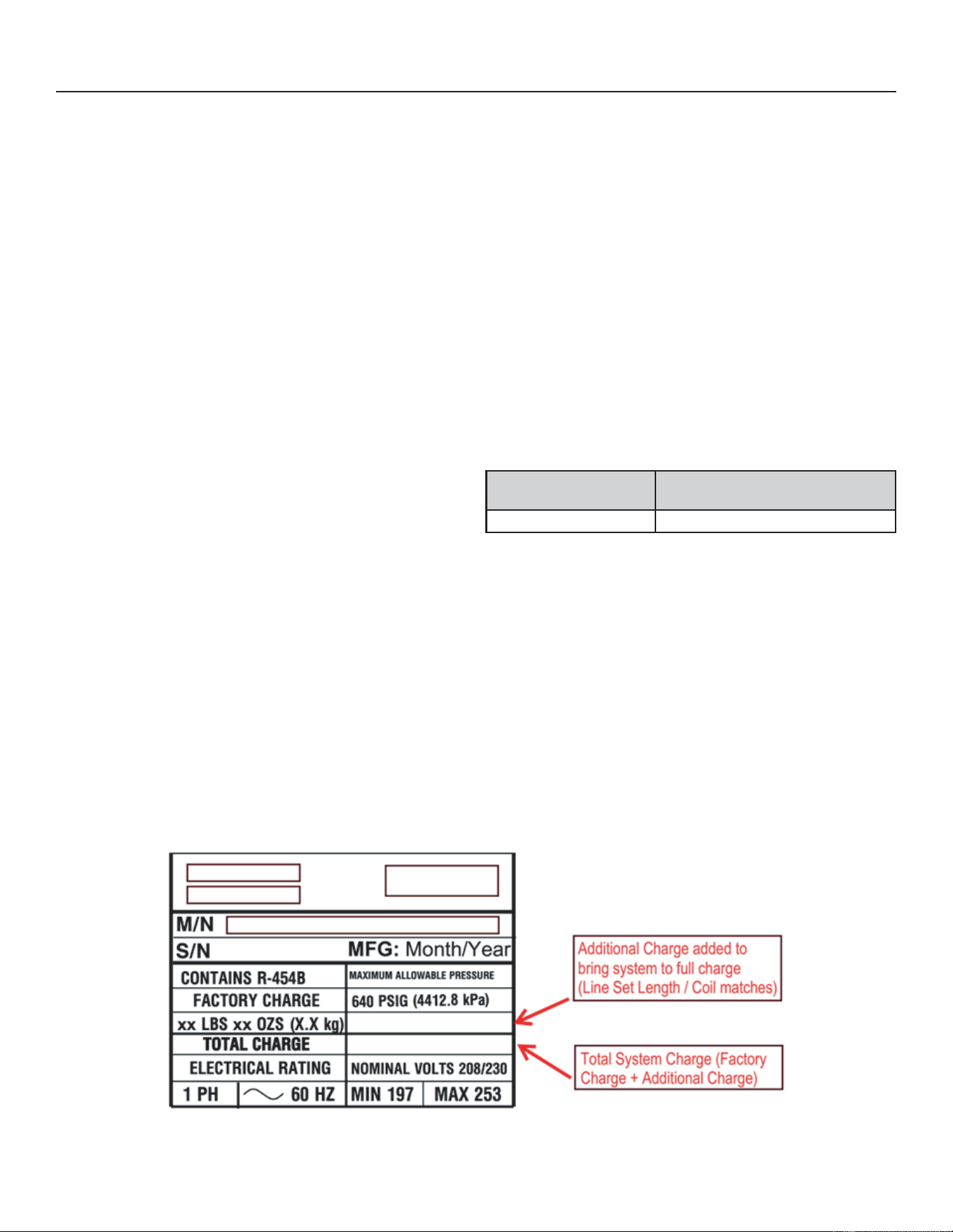
84
31-5000950 Rev. 0
Service Information
Charging
Verify the unit is electrically grounded before charging
WKHV\VWHP([WUHPHFDUHVKDOOEHWDNHQQRWWRRYHU¿OOWKH
refrigerating system.
Charge should be checked and adjusted using information
outlined in this section and in the tables provided on the
charging label on the unit’s control access panel.
R454B is a zeotropic blend of two refrigerants. At any
JLYHQUHIULJHUDQWSUHVVXUH5%ZLOOKDYHWZRVDWXUDWLRQ
WHPSHUDWXUHVDVDWXUDWHGOLTXLGWHPSHUDWXUHDQGD
saturated vapor temperature. See R454B Refrigerant
Pressure Temperature Chart in the installation and service
manual for saturation temperatures.
R454B Units must be charged with liquid refrigerant.
Follow conventional charging procedures when charging
the system. The technician is required to mark the total
FKDUJHRIWKHLQVWDOOHGV\VWHPRQWKHXQLWQDPHSODWH
which includes the nameplate charge (factory charge) and
additional charge that is added to the system at the time of
installation.
7KH5%UHIULJHUDQWF\OLQGHUVDUHSURYLGHGZLWKDóފ/+
ÀDUHFRQQHFWLRQWKHUHIRUHDóފ/+IHPDOHÀDUHDGDSWHUZLOO
be required. Connect manifold gauges and hoses following
conventional charging procedures. Position the R454B
refrigerant cylinder to deliver liquid refrigerant.
NS19H unit is factory charged with R454B. Refer to unit
Charging Label for baseline line set length for factory unit
charge and Additional Charge guidelines.
Initiate a call for cooling and allow the refrigerant pressures
and temperatures to stabilize. Adjust the charge to using
the subcooling method. The unit charging label provides
the target Subcooling Values. Record the liquid line
temperature. Measure the liquid line pressure and use
the value to determine the Saturated Liquid Temperature.
Calculate subcooling by subtracting the liquid line
temperature from the Saturated liquid temperature.
Subcooling = Saturated Liquid Temperature – Liquid
LineTemperature
Compare the results with the unit charging label.
2QFHV\VWHPFKDUJLQJKDVEHHQFRPSOHWHGWKHDGGLWLRQDO
charge and total charge must be marked on the unit
nameplate.
Total Charge = Factory Charge + Additional charge
The total charge is marked on the space adjacent to “Total
Charge”. See nameplate below. Detailed information is
given in the NS19H Installation and Service Procedures
PDQXDOZKLFKLVDYDLODEOHRQ
GEAppliancesAirandWater.com.
Refrigerant Charge per Line Set Length
Liquid Line Dia.
Ounces per 5 ft (G per 1.5 m)
Adjust From 15 ft (4.6 m) Line Set*
3/8” (9.5 mm) 3 Ounces per 5 ft (85 G per 1.5 m)
,IOLQHOHQJWKLVJUHDWHUWKDQIWPDGGWKLV
DPRXQW,IOLQHOHQJWKLVOHVVWKDQIWPVXEWUDFW
this amount.
NOTE – Insulate liquid line when it is routed through areas
where the surrounding ambient temperature could become
higher than the temperature of the liquid line or when
pressure drop is equal to or greater than 20 psig.
(NOTE - The nameplate is shown for illustration purposes only. Go to actual nameplate on outdoor unit for charge information.)
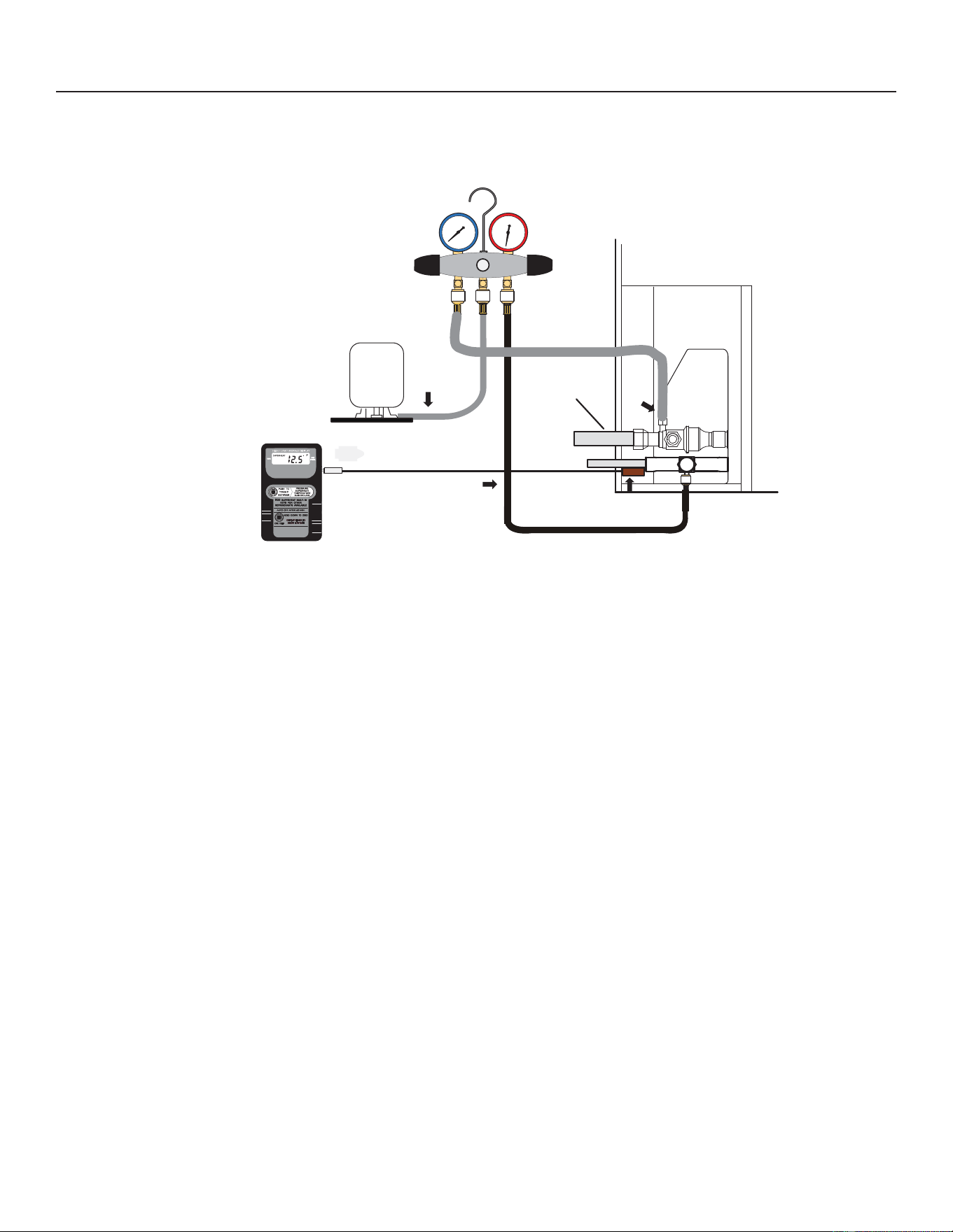
85
31-5000950 Rev. 0
Service Information
GAUGE SET
CONNECTIONS FOR TESTING AND CHARGING
A
C
D
B
MANIFOLD GAUGE SET
HIGHLOW
Outdoor Unit
Suction Line
Digital Scale
Refrigerant Tank
Charge in
Liquid Phase
Temperature
Sensor
To Liquid Line
Service Port
Temperature Sensor
(Liquid Line)
Figure 48. Gauge Set Connections
A. Close manifold gauge set valves and connect the center hose to a cylinder of r454b set for liquid phase charging.
B. Connect the manifold gauge set's low pressure side to the suction line service port.
C. Connect the manifold gauge set's high pressure side to the liquid line service port.
D. Position temperature sensor on liquid line near liquid line service port.
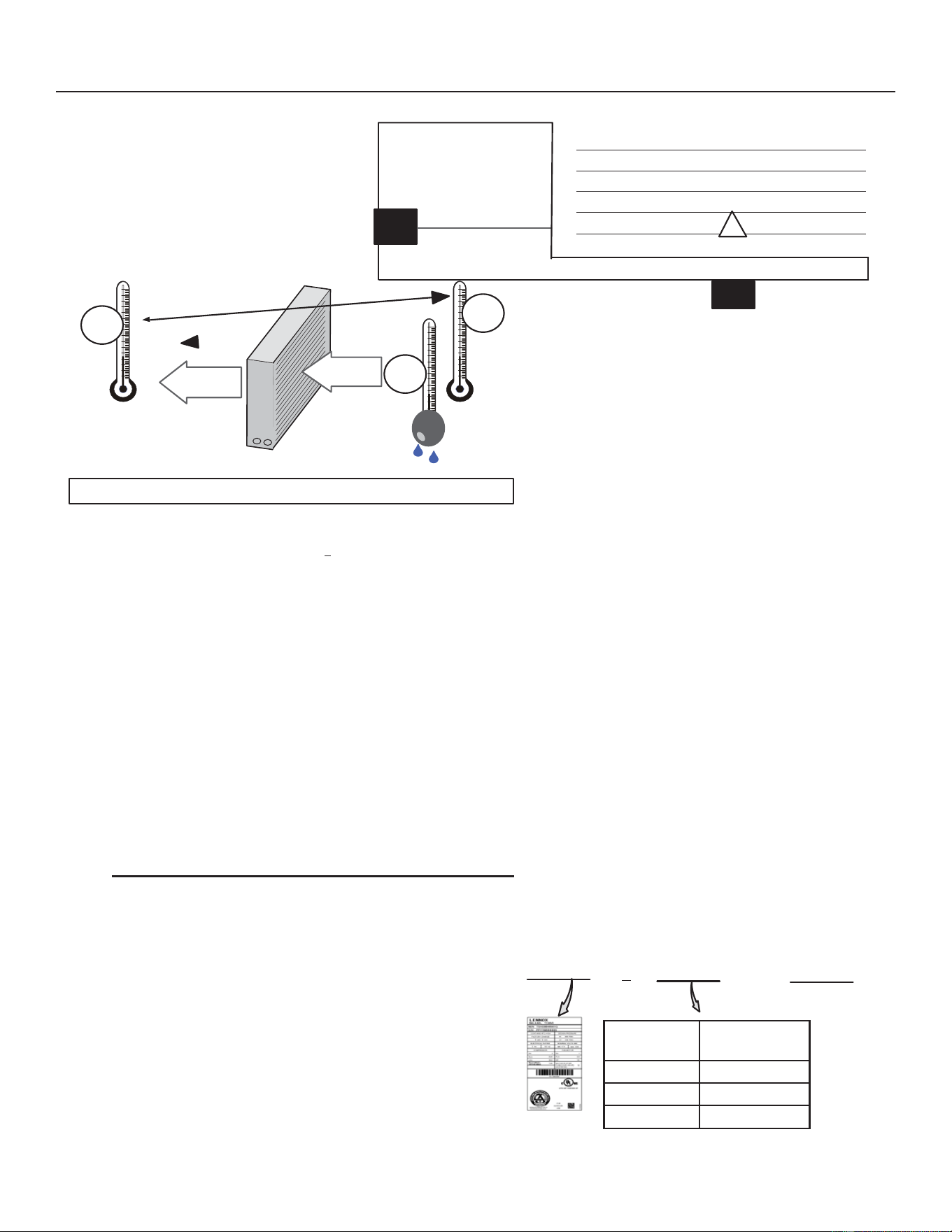
86
31-5000950 Rev. 0
AIRFLOW
INDOOR COIL
Figure 49. &KHFNLQJ,QGRRU$LUÀRZRYHU(YDSRUDWRU&RLOXVLQJ'HOWD7&KDUW
Use the WEIGH-INPHWKRGIRUDGGLQJLQLWLDOUHIULJHUDQWFKDUJHDQGWKHQXVHSUBCOOLING method for verifying
refrigerant charge.
WEIGH-IN
CHARGING METHOD
64ºF (17.7ºC) and Below
NOTE - Insulate liquid line when it is routed through areas where the surrounding ambient temperature could become
higher than the temperature of the liquid line or when pressure drop is equal to or greater than 20 psig
NOTE - The nameplate is shown for illustration purposes only. Go to actual nameplate on outdoor unit for charge
information.
Charging Formula for Liquid Line Charge Adjustments
[(Line Set oz./ft. x Total Length) – (Factory Charge for Line Set)] = Charge Adjustment
Example:
8QLWVDUHIDFWRU\FKDUJHGIRUIWPRIOLQHVHW
)DFWRU\FKDUJHIRULVR]IW[ RXQFHV
Service Information
Cº T
DROP
–DT=ºFACTION
53º 19 – 15 = 4 INCREASE THE AIRFLOW
58º 14 – 15 = -1 (WITHIN +3º RANGE) NO CHANGE
62º 10 – 15 = -5 DECREASE THE AIRFLOW
DT
80 24 24 24 23 23 22 22 22 20 19 18 17 16 15
78 23 23 23 22 22 21 21 20 19 18 17 16 15 14
76 22 22 22 21 21 20 19 19 18 17 16 15 14 13
74 21 21 21 20 19 19 18 17 16 16 15 14 13 12
72 20 20 19 18 17 17 16 15 15 14 13 12 11 10
70 19 19 18 18 17 17 16 15 15 14 13 12 11 10
57 58 59 60 61 62 63 64 65 66 67 68 69 70
TEMPERATURE OF AIR
ENTERING INDOOR COIL ºF
INDOOR
COIL
DRY
BULB
B
T
DROP
19º
A
DRY-BULB
WET-BULB ºF
A
72º
B
64º
C
53º
AIR
FLOW
AIR
FLOW
ALL TEMPERATURES ARE
EXPRESSED IN ºF
ASSUME DT = 15 AND A TEMP. = 72º, BELOW C TEMPERATURES REQUIRE ACTION:
1. Determine the desired DT — Measure entering air
temperature using Dry Bulb (A) and Wet Bulb (B). DT
is the intersecting value of A and B in the table (see
triangle).
2. Find Temperature Drop across coil — Measure the
Dry Bulb air temperature entering the coil (A and C).
Temperature Drop Formula: (T
DROP
) = A minus C.
3. Determine if fan needs adjustment — If the
GLႇHUHQFHEHWZHHQWKHPHDVXUHT
DROP
and the desired
DT (T
DROP
– DTLVZLWKLQQRDGMXVWPHQWLVQHHGHG
See example at left.
4. Adjust the Fan Speed — See indoor unit instructions
to increase/decrease fan speed.
NOTE:&KDQJLQJDLUÀRZDႇHFWVDOOWHPSHUDWXUHV
UHFKHFNWHPSHUDWXUHVWRFRQ¿UPWKDWWKH7HPSHUDWXUH
Drop and DT are within ±3º.
+
=
Liquid Line
Set Diameter
R454B (ounces
per foot)
5/16” 0.40
0.60
1.00
$PRXQWVSHFL¿HG
on nameplate
Adjust amount for
variation in line
set length and
liquid line diameter
using table below.
Total Charge
Figure 50. Using R454B Weigh-In Method

87
31-5000950 Rev. 0
Service Information
SUBCOOLING
CHARGING METHOD
(All charging MUST be performed while system is operating either at maximum speed or 100% demand.)
1. The diagnostic screen on the thermostat or outdoor control 7-Segment display will show indoor and outdoor motor
CFMs or RPMs.
2. Measure outdoor ambient temperature.
3. Connect Gauge Set.
4. Check liquid and vapor line pressures. Compare pressures with cooling mode normal operating pressures in the
DSSOLFDEOHFKDUJLQJVWLFNHUQRUPDORSHUDWLQJSUHVVXUHVDWPD[LPXPFDSDFLW\
NOTE7KHUHIHUHQFHWDEOHLVDJHQHUDOJXLGH([SHFWPLQRUSUHVVXUHYDULDWLRQV6LJQL¿FDQWGLႇHUHQFHVPD\PHDQ
improper charge or other system problem.
6HWWKHUPRVWDWIRUKHDWFRROGHPDQGGHSHQGLQJRQPRGHEHLQJXVHG
USING COOLING MODE²ZKHQWKHRXWGRRUDPELHQWWHPSHUDWXUHLV)&DQGDERYH7DUJHWVXEFRROLQJ
YDOXHVPD[LPXPFDSDFLW\LQDSSOLFDEOHFKDUJLQJVWLFNHUDUHEDVHGRQ)WR)&&LQGRRUUHWXUQ
DLUWHPSHUDWXUHLIQHFHVVDU\RSHUDWHKHDWLQJWRUHDFKWKDWWHPSHUDWXUHUDQJHWKHQVHWWKHLQLWLDOFRROLQJGHPDQGDW
maximum capacity. The preferred method is to use the “charge mode” jumper on the outdoor control. See Charge Mode
Jumper section on Page 83:KHQSUHVVXUHVKDYHVWDELOL]HGFRQWLQXHZLWK6WHS
6. Read the liquid line temperature; record in the LIQº space.
7.5HDGWKHOLTXLGOLQHSUHVVXUHWKHQ¿QGLWVFRUUHVSRQGLQJWHPSHUDWXUHLQWKHWHPSHUDWXUHSUHVVXUHFKDUWOLVWHGLQWKH
applicable charging sticker and record it in the SATº space.
8. Subtract LIQº temperature from SATº Temperature to determine subcooling; record it in SCº space.
9. Compare SCºUHVXOWVZLWKDSSOLFDEOHFKDUJLQJVWLFNHUEHLQJVXUHWRQRWHDQ\DGGLWLRQDOFKDUJHIRUOLQHVHWDQGRU
match-up.
10.,IVXEFRROLQJYDOXHLVJUHDWHUWKDQVKRZQLQDSSOLFDEOHFKDUJLQJVWLFNHUIRUWKHDSSOLFDEOHXQLWUHPRYHUHIULJHUDQWLI
OHVVWKDQVKRZQDGGUHIULJHUDQW
11. ,IUHIULJHUDQWLVDGGHGRUUHPRYHGUHSHDW6WHSVWKURXJKWRYHULI\FKDUJH
12. Disconnect gauge set and re-install both the liquid and suction service valve caps.
Figure 51. Using R454B Subcooling Method - High Speed (High Capacity)
SATº
LIQº –
SCº =
USE
COOLING
MODE
60ºF (15ºC)
USE
HEATING
MODE
88
31-5000950 Rev. 0
Service Information
Table 21. R454B Temperature (°F) - Pressure (Psig)
Pressure
(psig)
Satu-
rated Liquid
7HPS)
Saturated
Vapor Temp
)
Pressure
(psig)
Satu-
rated Liquid
7HPS)
Saturated
Vapor Temp
)
Pressure
(psig)
Satu-
rated Liquid
7HPS)
Saturated
Vapor Temp
)
Pressure
(psig)
Satu-
rated Liquid
7HPS)
Saturated
Vapor Temp
)
0 -58.9 -57.1 158 58.9 61.3 272 93.0 95.4 362 113.4 115.6
25 -19.2 -17.2 160 59.6 62.0 274 93.5 95.9 364 113.8 116.0
30 -13.9 -11.8 165 61.4 63.8 276 94.0 96.4 366 114.2 116.4
35 -9.0 -6.9 170 63.1 65.5 278 94.5 96.9 368 114.6 116.8
40 -4.4 -2.3 175 64.9 67.3 280 95.0 97.4 370 115.0 117.2
45 -0.2 1.9 180 66.6 69.0 282 95.5 97.9 372 115.4 117.6
50 3.7 5.9 185 68.2 70.6 284 96.0 98.4 374 115.8 118.0
55 7.5 9.7 190 69.8 72.2 286 96.5 98.8 376 116.2 118.4
60 11.0 13.2 195 71.4 73.8 288 97.0 99.3 378 116.6 118.8
65 14.4 16.6 200 73.0 75.4 290 97.5 99.8 380 117.0 119.2
70 17.6 19.8 202 73.6 76.0 292 97.9 100.3 382 117.4 119.6
75 20.6 22.9 204 74.2 76.6 294 98.4 100.7 384 117.7 119.9
80 23.6 25.9 206 74.9 77.3 296 98.9 101.2 386 118.1 120.3
85 26.4 28.7 208 75.5 77.9 298 99.4 101.7 388 118.5 120.7
90 29.1 31.4 210 76.1 78.5 300 99.8 102.2 390 118.9 121.1
95 31.7 34.0 212 76.7 79.1 302 100.3 102.6 392 119.3 121.5
100 34.3 36.6 214 77.3 79.7 304 100.8 103.1 394 119.7 121.9
102 35.3 37.6 216 77.9 80.2 306 101.2 103.5 396 120.1 122.2
104 36.2 38.6 218 78.4 80.8 308 101.7 104.0 398 120.5 122.6
106 37.2
39.5 220 79.0 81.4 310 102.1 104.4 400 120.8 123.0
108 38.1 40.5 222 79.6 82.0 312 102.6 104.9 405 121.8 123.9
110 39.1 41.4 224 80.2 82.6 314 103.0 105.4 410 122.7 124.9
112 40.0 42.4 226 80.8 83.1 316 103.5 105.8 415 123.6 125.8
114 40.9 43.3 228 81.3 83.7 318 103.9 106.2 420 124.6 126.7
116 41.8 44.2 230 81.9 84.3 320 104.4 106.7 425 125.5 127.6
118 42.7 45.1 232 82.4 84.8 322 104.8 107.1 430 126.4 128.5
120 43.6 46.0 234 83.0 85.4 324 105.3 107.6 435 127.3 129.4
122 44.5 46.9 236 83.6 86.0 326 105.7 108.0 440 128.2 130.2
124 45.4 47.7 238 84.1 86.5 328 106.2 108.5 445 129.0 131.1
126 46.2 48.6 240 84.7 87.1 330 106.6 108.9 450 129.9 132.0
128 47.1 49.4 242
85.2 87.6 332 107.0 109.3 460 131.6 133.7
130 47.9 50.3 244 85.8 88.1 334 107.5 109.7 470 133.3 135.3
132 48.8 51.1 246 86.3 88.7 336 107.9 110.2 480 135.0 137.0
134 49.6 51.9 248 86.8 89.2 338 108.3 110.6 490 136.7 138.6
136 50.4 52.8 250 87.4 89.7 340 108.8 111.0 500 138.3 140.2
138 51.2 53.6 252 87.9 90.3 342 109.2 111.5 510 139.9 141.8
140 52.0 54.4 254 88.4 90.8 344 109.6 111.9 520 141.5 143.3
142 52.8 55.2 256 88.9 91.3 346 110.0 112.3 530 143.0 144.8
144 53.6 56.0 258 89.5 91.8 348 110.5 112.7 540 144.5 146.3
146 54.3 56.7 260 90.0 92.4 350 110.9 113.1 550 146.1 147.8
148 55.1 57.5 262 90.5 92.9 352 111.3 113.5 560 147.5 149.2
150 55.9 58.3 264 91.0 93.4
354 111.7 114.0 570 149.0 150.7
152 56.6 59.0 266 91.5 93.9 356 112.1 114.4 580 150.5 152.1
154 57.4 59.8 268 92.0 94.4 358 112.5 114.8 590 151.9 153.5
156 58.1 60.5 270 92.5 94.9 360 112.9 115.2 600 153.3 154.8
NOTE:
1. R-454B is a zeotropic blend and must be charged with liquid refrigerant only.
2. Saturated liquid temperature is used to calculate liquid subcooling.
3. Saturated vapor temperature is used to calculate suction superheat.
4. See unit charging label for subcooling values and additional charging information.
89
31-5000950 Rev. 0
Service Information
Changing Label
R454B CHARGING INFORMATION – FOR COMPLETE CHARGING DETAILS, REFER TO THE OUTDOOR UNIT
INSTALLATION AND SERVICE PROCEDURE
Maintenance checks using the Normal Operating Pressures
table
Table 2 may be used to help perform maintenance checks. This
table is not a procedure for charging the system and any minor
YDULDWLRQVLQWKHSUHVVXUHVPD\EHH[SHFWHGGXHWRGLႇHUHQFHVLQ
LQVWDOODWLRQV+RZHYHUVLJQL¿FDQWGHYLDWLRQVFRXOGPHDQWKDWWKH
system is not properly charged or that a problem exists with some
component in the system.
Charge Using the Subcooling Method
• Cooling Mode±:KHQWKHRXWGRRUDPELHQWWHPSHUDWXUHLV)
&DQGDERYHXVHWKHFRROLQJPRGHWRDGMXVWWKHFKDUJH
using the subcooling method. Target subcooling values in table 1
DUHEDVHGRQWR)&LQGRRUUHWXUQDLUWHPSHUDWXUH
• Heating Mode – When the outdoor ambient temperature is
EHORZ)&XVHWKHKHDWLQJPRGHWRDGMXVWWKHFKDUJH
using the subcooling charge levels (table ). Target subcooling
YDOXHVLQWDEOHDUHEDVHGRQ)&LQGRRUUHWXUQ
air temperature.
Matchups/Charge Levels and Line Set Lengths
Table 2 lists all the Lennox recommended indoor unit matchups
along with the charge levels for the various sizes of outdoor units.
Charge levels on the unit nameplate are based on installations
ZLWKIWPOLQHVHWVRQOLQHVHWVZLWK´PPOLTXLGOLQH
add 3oz. additional refrigerant for every 5ft. longer than 30ft. If
OLQHOHQJWKLVOHVVWKDQIWVXEWUDFWWKLVDPRXQWVHH,QVWDOODWLRQ
Instructions for more details).
Charge Using the Weigh-in Method
,IWKHV\VWHPLVYRLGRIUHIULJHUDQWORFDWHDQGUHSDLUDQ\OHDNV
and then weigh in the refrigerant charge into the unit. For charge
DGMXVWPHQWVEHVXUHWRFRQVLGHUOLQHVHWOHQJWKGLႇHUHQFHVDQG
UHIHUULQJWRWDEOHDGMXVWIRUWKHPDWFKXSGLႇHUHQFH
1 - Recover the refrigerant from the unit.
2 - Conduct leak check; evacuate as previously outlined.
:HLJKLQWKHXQLWQDPHSODWHFKDUJHDGMXVWLQJIRUPDWFKXS
DQGOLQHVHWOHQJWKGLႇHUHQFHV,IZHLJKLQJIDFLOLWLHVDUHQRW
available use the Subcooling method.
Temperature Cooling Operation – Liquid Line Pressure / Vapor Line Pressure
) -036 -060
65 245/128 255/124
75 284/130 297/126
85 328/132 343/127
95 375/133 393/129
105 426/136 447/131
115 479/138 500/137
Temperature Heating Operation – Liquid Line Pressure / Vapor Line Pressure
20 262/36 294/47
30 397/70 313/61
40 314/83 332/71
50 329/99 364/93
60 346/115 382/112
Table 1 - Normal Operating Pressure (Liquid ±10 and Vapor ±5 psig)

90
31-5000950 Rev. 0
Notes

91
31-5000950 Rev. 0
Notes

92
31-5000950 Rev. 0
All specifications and illustrations subject
to change without notice and without
incurring obligations.