Thermostats
Wireless Digital
GEAppliances.com
Backlight . . . . . . . . . . . . . . . . . . . . . . . . . . . . . . . . . . . . . . . . . .5
Batteries . . . . . . . . . . . . . . . . . . . . . . . . . . . . . . . . . . . . . . . . . .4
Buttons . . . . . . . . . . . . . . . . . . . . . . . . . . . . . . . . . . . . . . . . . . .5
Fahrenheit/Celsius . . . . . . . . . . . . . . . . . . . . . . . . . . . . . . . .5
Frequently Asked Questions . . . . . . . . . . . . . . . . . .9, 10
Important Safety Information . . . . . . . . . . . . . . . . . . . .2
Introduction Overview . . . . . . . . . . . . . . . . . . . . . . . . . . . .3
Linking Thermostat and Receiver . . . . . . . . . . . . . . . . .7
Specifications . . . . . . . . . . . . . . . . . . . . . . . . . . . . . . . . . . . . .2
Thermostat and Receiver . . . . . . . . . . . . . . . . . . . . . . . . .6
Thermostat Link Reset . . . . . . . . . . . . . . . . . . . . . . . . . . . .8
Troubleshooting Tips . . . . . . . . . . . . . . . . . . . . . . . . . . . .11
Warranty . . . . . . . . . . . . . . . . . . . . . . . . . . . . . . . . . . . . . . . .12
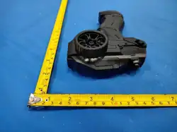
RAK348R1 – Heat Pump
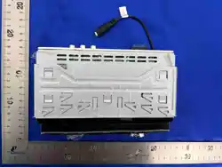
Receiver (2-Stage)
RAK348T1 – Thermostat
RAK364R1 – Strip Heat
Receiver (1-Stage)
RAK364T1 – Thermostat
Owner’s Manual
49-7615 05-09 JR
Español
Para consultar una version
en español de este manual
de instrucciones, visite
nuestro sitio de internet
Zoneline.com/literature.
Française
Pour une version française de ce
manuel d’utilisation, veuillez visiter
notre site web à l’adresse
Zoneline.com/literature.
with Receivers
Important safety information.
Specifications.
WARNING!
RISK OF ELECTRIC SHOCK. Can cause injury or death: Turn off power at the
main service panel by removing the fuse or switching the appropriate circuit
breaker to the OFF position before installing the thermostat receiver.
GE IS NOT RESPONSIBLE FOR ANY RADIO OR TV INTERFERENCE CAUSED BY UNAUTHORIZED
MODIFICATIONS TO THIS EQUIPMENT. SUCH MODIFICATIONS COULD VOID THE USER’S
AUTHORITY TO OPERATE THE EQUIPMENT.
THIS EQUIPMENT COMPLIES WITH PART 15 OF THE FCC RULES. OPERATION IS SUBJECT
TO THE FOLLOWING TWO CONDITIONS: (1) THIS DEVICE MAY NOT CAUSE HARMFUL
INTERFERENCE, AND (2) THIS DEVICE MUST ACCEPT ANY INTERFERENCE RECEIVED,
INCLUDING INTERFERENCE THAT MAY CAUSE UNDESIRED OPERATION.
• Do not use air conditioning when the outdoor temperature is below 50 degrees; this can
damage your A/C system and cause personal injuries.
• Use this thermostat only as described in this manual.
Before you begin – Read all instructions before using device. Follow all warnings and cautions.
SAVE THESE INSTRUCTIONS
Electrical ratings: • Thermostat: DC Power 3.0 VDC (4 “AA” batteries included)
• Receiver: 24 VAC (18–30 VAC); 120 mA
Operating temperature range: 40°F–99°F (4°C–37°C)
Temperature set range
Heat mode: 50°F (10°C)–84°F (29°C)
Cool mode: 64°F (18°C)–99°F (37°C)
Resolution: ± 1°F (± 1.0°C)
System configurations: RAK348R1 receiver – 2-stage heat (heat pump/resistance heat);
RAK364R1 receiver – 1-stage heat (resistance heat); 1-stage cool
Timing: Anti-short cycle: 3 minutes (minimum compressor off time)
Terminals: R, GL, GH, B, Y, W, C
2
3
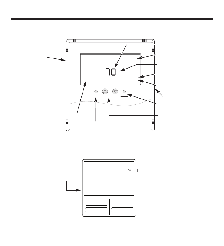
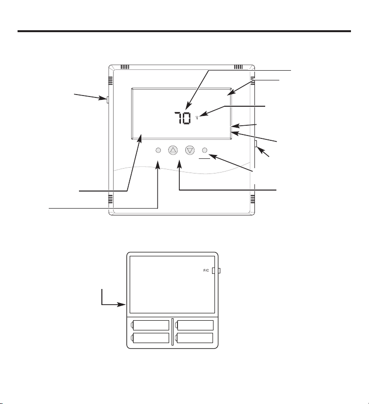
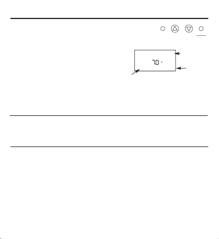
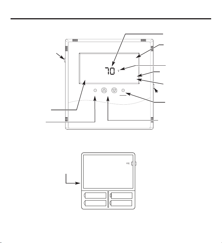
Introduction overview.
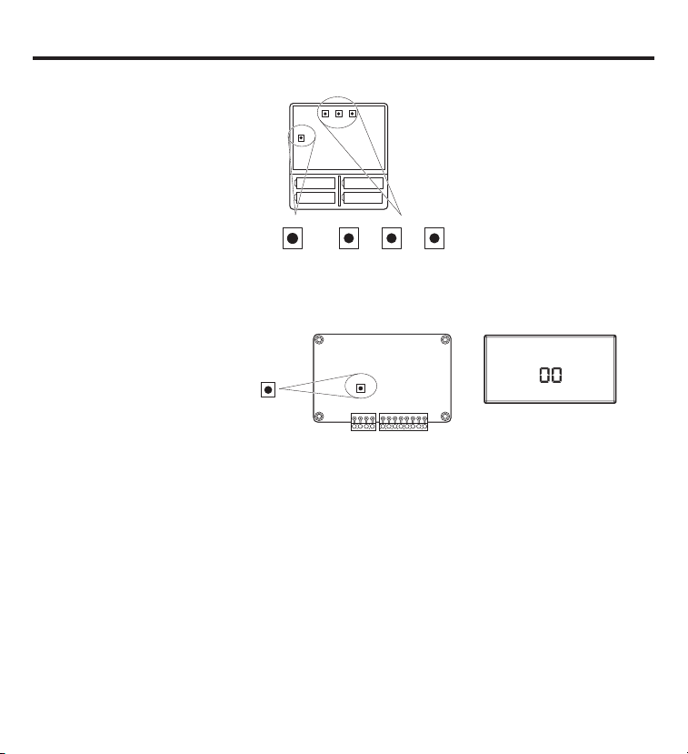
THERMOSTAT CONTROL – Back
Fan
Hea t
Cool
Up
Down
Fan Auto
COOL
OFF
70
O
O
Set Point
Hold
F/C
Light
Current room temperature
Toggles display –
Fahrenheit/Celsius
Thermostat will operate on
either Set A, Set B or both.
When changing batteries,
replace one set at a time to
avoid losing the set point
information. Always replace
with all new batteries. Never
use a mix of old and new.
Battery orientation
is critical.
Heating and cooling set points will be lost if all of the batteries are removed or depleted. The thermostat
and receiver(s) will remain linked, but the set point temperatures will need to be reset.
Thermostat
opened back
Fan operating status
Fan control
Operating mode indication –
HEAT, COOL, OFF
RF connection with a control mode
Indicates holding of Set Point
temperature
Current Set Point temperature
Momentary backlight button
Changes operating mode –
HEAT, COOL, OFF
Changes Set Point temp
Circuit Board
Set A
Set A
Set B
Set B
THERMOSTAT CONTROL – Front

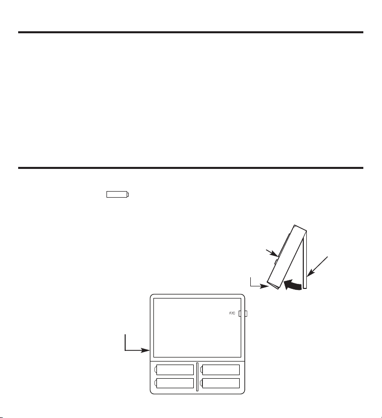
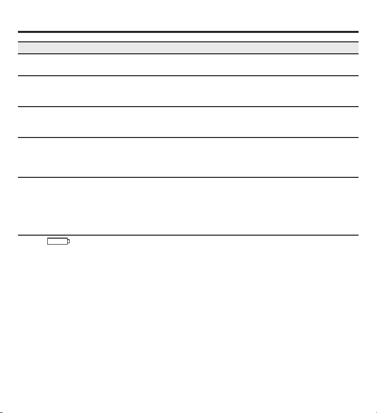
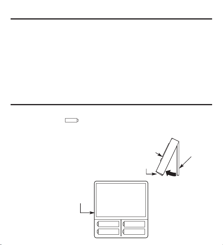
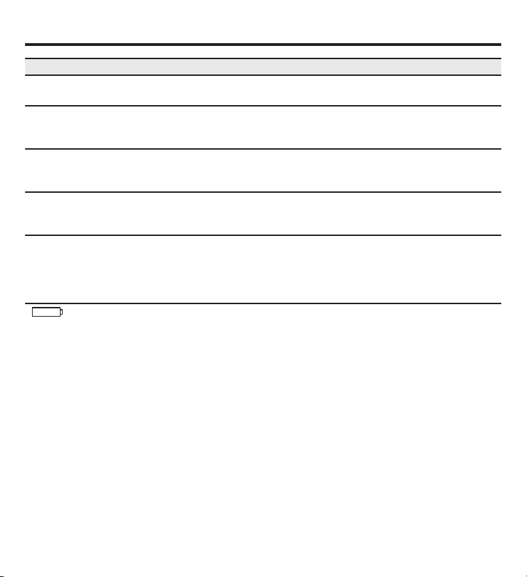
Installing/Changing
A low-battery icon will light on the thermostat display when the batteries are close to
being exhausted. The thermostat is designed to use standard AA-size 1.5-volt batteries. If the
batteries are depleted, the heating/cooling system will go to the OFF state.
Replacing Batteries
To open the thermostat, remove the security screw
(#2 Phillips or #2 security screw). Using both hands,
press the two push tabs on the bottom of the
thermostat housing, while pulling the front of
the thermostat away from the base.
The thermostat operates with 4 AA batteries.
Batteries are paired, one set on top of the other.
4
Introduction.
This two-part wireless thermostat system is designed to provide remote temperature control.
Powered by four AA batteries, the thermostat will operate for approximately 1 year and can be
mounted in any suitable location that will ensure good temperature control. A large LCD display
provides the user with current space temperature, set point temperature and system status
information. The second part of the system is the receiver. The receiver interfaces with the
desired HVAC equipment and communicates with its thermostat using unlicensed 900MHz
radio frequency energy. At the time of installation, the thermostat is linked to one or more
receivers. A thermostat and receiver that have been linked will not interfere with or be affected
by any other thermostat or receiver in adjacent rooms, apartments or neighboring homes.
Batteries.
Thermostat
cover
Latches and
security screw
Base plate
Thermostat will operate
on either Set A, Set B
or both. When changing
batteries, replace one
set at a time to avoid
losing the set point
information. Always
replace with all new
batteries. Never use
a mix of old and new.
Battery orientation
is critical.
Circuit Board
Set A
Set A
Set B
Set B
Thermostat
opened back
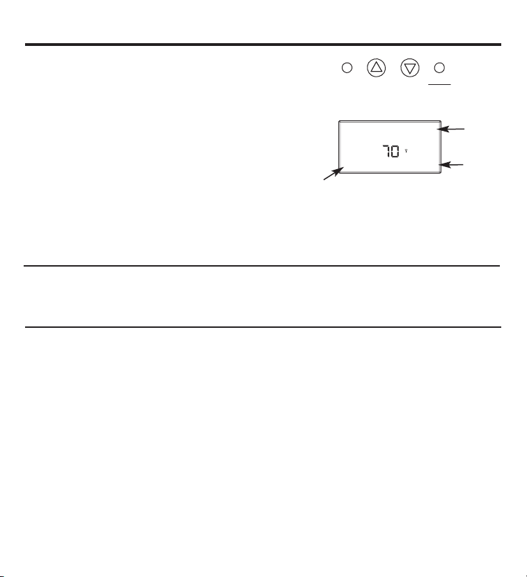
Buttons.
A four-button cluster is located on the front of the thermostat.
Fan
Heat
Cool
Up
Down
These buttons are used in adjusting fan operation, changing
the set point temperature up or down and changing the
operating mode of the thermostat.
Fan Control
There are three options regarding the fan control.
Fan Auto – Unit adjusts the fan speed automatically as required
Fan 1 – Low-speed fan
Fan 2 – High-speed fan
Fahrenheit/Celsius
The button located on the left side of the thermostat controls the display of the temperature
and allows you to toggle between Fahrenheit and Celsius. It is marked F/C on the left front.
Backlight
A single button on the right side of the thermostat activates the display backlight. The backlight
will illuminate the display for 5 seconds. Backlighting takes significant energy from the batteries
and should be used sparingly. Frequent use of the backlight function will noticeably reduce
battery life.
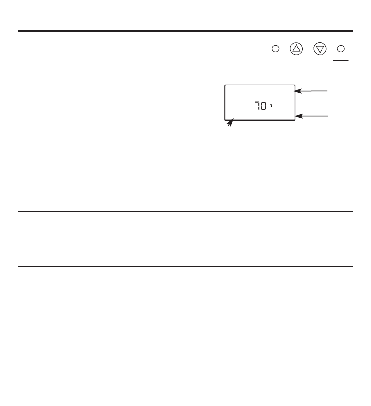
Fan Auto
COOL
70
O
O
Set Point
Hold
Mode of
operation
Set Point
5
Fan status

6
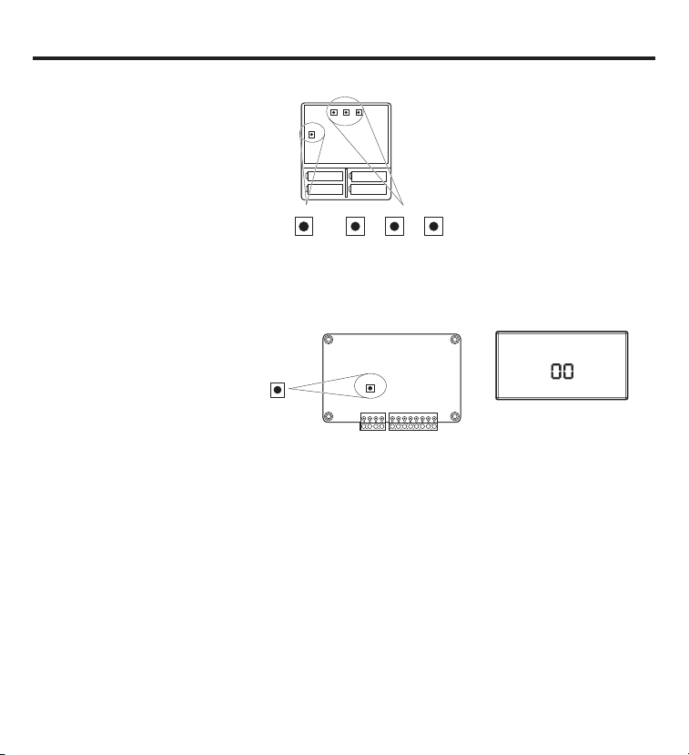
Thermostat and receiver.
The thermostat and receiver will not operate as a system until they are “linked” together
through the installation process. The linking process binds one or more receivers to a
thermostat so that they will communicate with each other as a control system. Up to
eight (8) receivers can be linked to a single thermostat. Until linked, a control receiver will
not operate. Once linked, a control receiver will only respond to its specific thermostat.
A thermostat and receiver that have been linked will not interfere with or be affected by any
other thermostat or receiver in adjacent rooms, apartments or neighboring homes. Linking
information is stored in memory—it is not necessary to relink a thermostat and receiver if
the thermostat batteries are removed or after a power outage.
If multiple installation teams are installing and linking thermostats at the same time, coordinate
the activity to avoid the possibility of installers simultaneously attempting to perform the linking
process. Because this is an RF system, installers in nearby rooms/areas where it is possible RF
overlap could exist run the risk of interfering with each other. Installation and linking activity
going on around a system already installed will not interfere with it.

SW12-RESET SW4-INSTALL SW9-LINK
SW12
-
RESET SW4
-
INSTALL SW9
-
LINK
PB1-NETWORK
PB1-NETWORK
PB1–NETWORK
Used to uninstall the thermostat
from receiver(s) it has been
linked to.
SW12–RESET
Master Reset – Returns thermostat
to all factory defaults.
SW4–INSTALL
Starts an installation session.
SW9–LINK
Used to link the thermostat to
control receiver(s).
Node
Good
Please Wait
Install
HEAT
COOL
NOTE: The display always blinks
the item that is active and can
be changed.
Linking the thermostat and receiver.
1. Press the SW4-INSTALL button
inside the thermostat. Press the
HEAT/COOL button on the front
of the thermostat to select your
choice. Press the UP button to set
the receiver number (0–7) and
press the HEAT/COOL button
to set the receiver.
2. Press the SW9-LINK button
inside the thermostat.
Within 5 seconds, press the
RESET/LINK button (PB3)
on the receiver. “Good” will
appear if linked. “Bad” will
appear if not linked.
3. Press the SW4-INSTALL
button to complete the
installation session.
Thermostat Internal Buttons
Display
PB3-RESET/LINK
PB3-RESET/LINK
Receiver Internal Button
Removing or Delinking a Receiver
Unlike installing a receiver, the procedure to remove or “delink” a receiver will uninstall all
receivers installed to the thermostat at once. You cannot remove a single receiver at a time.
1. Press the SW4-INSTALL button inside the thermostat. The ”Install“ icon will flash. Press the UP
button to get the “Remove” choice and press the HEAT/COOL button to select. The “Heat”
and “Cool” icons will be displayed and all display items will be on steady; nothing will be
flashing.
2. Press the SW9-LINK button on the back of the thermostat printed circuit board. Within
5 seconds, press the PB3 RESET/LINK button on the receiver. When the SW9-LINK button
is pressed, the thermostat will display the “Please Wait” message in the bottom right corner
of the LCD while it searches for a receiver. Once the thermostat finds its installed receiver(s),
linking information is removed from the receivers and the thermostat, the “Please Wait”
message is extinguished and a “Good” message will appear.
3. To complete the process, press the SW4-INSTALL button.
7

Thermostat link reset.
8
If there is difficulty installing a receiver, perform the following:
1. Press the SW4-INSTALL button inside the thermostat. The ”Install“ icon will flash. You only
need to begin the installation session to perform this reset.
2. Press and hold the PB1-NETWORK button on the inside of the thermostat board for
approximately 2 seconds.
3. Press the SW4-INSTALL button to end the reset procedure.
No response is displayed. All previous installation records will be wiped from thermostat
memory. You can continue from this point with the installation procedure. The PB1-NETWORK
button will only reset the thermostat installation data base if the thermostat is already in an
Installation Session (SW4-INSTALL button has been pressed). Otherwise, the PB1-NETWORK
button will have no effect.

9
Frequently asked questions.
“Where should I locate my thermostat?”
For best results, the thermostat should be located approximately 5 feet above the floor on an
inside wall in an area with good air circulation. A thermostat should not be located where air is
stagnating, such as behind doors, in corners or under cabinets. Hot or cold drafts from air ducts
and windows should be avoided. Avoid direct heat from the sun, lighting fixtures, appliances,
fireplaces, etc.
“What does the antenna symbol on the display mean?”
The thermostat displays the antenna symbol as an indication that it is communicating with its
receiver(s). If, after several tries, communication is not established, the antenna symbol will
go out.
“What do I do if the antenna symbol is no longer displayed?”
Check power to the HVAC equipment in which the receiver is installed. With power restored,
force the thermostat to talk to the receiver(s) by pushing the FAN button or running the set
point temperature above or below the room temperature (above in heating, below in cooling).
The thermostat will also automatically try to communicate within a maximum of 10 minutes
from the last attempt. If communication is successful, the antenna icon will turn back on.
Coincidental RF interference could cause a temporary loss of communication. In virtually
all such cases, the interference is temporary.
“Can I run multiple heating or cooling loads with one thermostat?”
Yes. In fact, one thermostat can control up to eight (8) different receivers.
“Can I use another thermostat without interference?”
Yes. This wireless thermostat and its receiver(s) will talk between themselves, but will never
respond to or control another thermostat in adjacent rooms, apartments or neighboring
homes.
“When my a/c turns off, why can’t I immediately make it run again?”
This is normal. What you are experiencing is called an anti short-cycle delay. Because of high
pressure in the system, it is not a good idea to start your air conditioner immediately after it
has just shut down. The thermostat automatically prevents this from happening by imposing
a delay of approximately 3 minutes.

Frequently asked questions (cont.).
“I just installed the thermostat and the antenna symbol goes on and off. What should I do?”
A weak RF signal between the thermostat and one or more receivers is the cause. The further
away the thermostat and receiver are from each other, the weaker the signal. Distance and/or
something shielding or blocking the RF signal is the likely cause. Distance is typically not a
problem. The most common cause for this is an object acting as a shield, such as sheet metal.
Changing the position of the thermostat may be required.
NOTE: Always seek out a professional electrical and HVAC contractor when working with your
heating and cooling system and the electrical wiring in your home or commercial property.
Always consult with an HVAC contractor and/or original equipment manufacturer before
modifying any equipment.
“The display on the thermostat is blank. What happened?”
A blank display indicates that your batteries are depleted. When the “Low Battery” icon
comes on, there are only a couple of weeks of battery life remaining. We recommend that
when you change batteries, always use batteries that you know are fresh. Use four (4) new
high-quality AA batteries. If you are using the wireless thermostat to control a heating system,
we recommend as a general practice putting fresh batteries in at the start of the heating
season.
10
Troubleshooting tips.
No display Make sure batteries are fresh and installed correctly. See the “Batteries”
section in this manual.
System fan does not Verify that wiring is correct.
come on properly
Fan runs continuously Check Fan Auto setting. If set to Fan 1 or Fan 2 position, fan will run
continuously.
Room temperature is If a wired thermostat was removed, make sure that the hole in the wall
not correct was sealed with nonflammable insulation or putty, or use a wall plate
obtained from a local hardware or home building store.
Compressor doesn’t run There is a protective time delay (approximately 3 minutes) to prevent
or turn on immediately tripping of the compressor overload. For this reason, the unit may not
when changing function start normal cooling or heating for 3 minutes after it is turned back on.
or setting
displays on screen Replace batteries with 4 fresh AA alkaline batteries.
Problem Solution
11
Thermostat Warranty.
For The Period Of: GE Will Replace:
One Year Limited Replacement of the thermostat which fails due to a defect in materials or workmanship.
From the date of the
original purchase
What GE Will Not Cover:
■ Service trips to your location.
■ Improper installation. If you have an installation problem, contact your installer. You are responsible for providing
adequate electrical connections to the product.
■ Failure of the product resulting from modifications to the product or due to unreasonable use, including failure to
provide reasonable and necessary maintenance.
■ In commercial locations, labor necessary to move the unit, after it has been initially installed, to a location where it is
accessible for service by an individual technician; or, if the instructions included in this manual have been disregarded.
■ Replacement of location fuses or the resetting of circuit breakers.
■ Batteries.
■ Damage to the product caused by improper power supply voltage, accident, fire, floods or acts of God.
■ Incidental or consequential damage caused by possible defects with this thermostat.
Staple your receipt here.
Proof of the original purchase date
is needed to validate the warranty.
This warranty is extended to the original purchaser and any succeeding owner for products purchased for use within the USA
and Canada. In Alaska, the warranty excludes the cost of shipping or service calls to your site.
Some states or provinces do not allow the exclusion or limitation of incidental or consequential damages. This warranty gives
you specific legal rights, and you may also have other rights which vary from state to state or province to province. To know
what your legal rights are, consult your local, state or provincial consumer affairs office or your state’s Attorney General.
Warrantor: General Electric Company. Louisville, KY 40225
EXCLUSION OF IMPLIED WARRANTIES—Your sole and exclusive remedy is product exchange as provided in this
Limited Warranty. Any implied warranties, including the implied warranties of merchantability or fitness for a
particular purpose, are limited to one year or the shortest period allowed by law.
Printed in China
All warranty service provided by our Factory Service Centers or an authorized
Customer Care
®
technician. To schedule service, on-line, visit us at
GEAppliances.com, or call 800.GE.CARES (800.432.2737). For service in Canada,
contact Gordon Williams Corp. at 1.888.209.0999. Please have serial number
and model number available when calling for service.
Thermostats
www.electromenagersge.ca
Boutons . . . . . . . . . . . . . . . . . . . . . . . . . . . . . . . . . . . . . . . . . . . . . . . . . .5
Caractéristiques techniques . . . . . . . . . . . . . . . . . . . . . . . . . . . . . .2
Conseils de dépannage . . . . . . . . . . . . . . . . . . . . . . . . . . . . . . . . .11
Consignes de sécurité importantes . . . . . . . . . . . . . . . . . . . . . .2
Fahrenheit/Celsius . . . . . . . . . . . . . . . . . . . . . . . . . . . . . . . . . . . . . . . .5
Garantie . . . . . . . . . . . . . . . . . . . . . . . . . . . . . . . . . . . . . . . . . . . . . . . .12
Piles . . . . . . . . . . . . . . . . . . . . . . . . . . . . . . . . . . . . . . . . . . . . . . . . . . . . . .4
Questions fréquemment posées . . . . . . . . . . . . . . . . . . . . .9, 10
Réinitialisation de la liaison avec le thermostat . . . . . . . . . . .8
Relier le thermostat et le récepteur . . . . . . . . . . . . . . . . . . . . . . .7
Rétroéclairage . . . . . . . . . . . . . . . . . . . . . . . . . . . . . . . . . . . . . . . . . . . .5
Thermostat et récepteur . . . . . . . . . . . . . . . . . . . . . . . . . . . . . . . . . .6
Vue d’ensemble . . . . . . . . . . . . . . . . . . . . . . . . . . . . . . . . . . . . . . . . . .3
RAK348R1 – Récepteur de
Pompe à Chaleur (2 étages)
RAK348T1 – Thermostat
RAK364R1 – Récepteur
pour Élément Thermique
à Lame (1 étage)
RAK364T1 – Thermostat
Manuel du propriétaire
49-7615-F 07-09 JR
sans fil avec récepteurs
Consignes de sécurité importantes.
Caractéristiques techniques.
AVERTISSEMENT ! RISQUE DE CHOC ÉLECTRIQUE. Peut provoquer des
blessures voire la mort. Déconnectez de l’alimentation électrique au niveau du tableau électrique central en
retirant un fusible ou en déclenchant le disjoncteur approprié avant d’installer le récepteur du thermostat.
GE N’EST PAS RESPONSABLE DU BROUILLAGE DES ONDES RADIO OU TÉLÉVISUELLES RÉSULTANT
DE MODIFICATIONS NON AUTORISÉES DE CET ÉQUIPEMENT. DE TELLES MODIFICATIONS PEUVENT
ANNULER LE DROIT DE L’UTILISATEUR DE SE SERVIR DE L’ÉQUIPEMENT.
CET APPAREIL EST CONFORME AUX PRESCRIPTIONS DE LA PARTIE 15 DES RÈGLES DE LA FCC.
LE FONCTIONNEMENT DE CET ÉQUIPEMENT EST ASSUJETTI AUX DEUX CONDITIONS SUIVANTES :
(1) CET APPAREIL NE DOIT PAS CAUSER DE BROUILLAGE PRÉJUDICIABLE; ET (2) CET APPAREIL
DOIT ACCEPTER TOUT BROUILLAGE QU’IL REÇOIT, Y COMPRIS CELUI POUVANT ENTRAÎNER
UN FONCTIONNEMENT INDÉSIRABLE.
• N’utilisez pas un climatiseur lorsque la température extérieure descend sous 50 ºF (10 ºC); cela
pourrait endommager le climatiseur et causer des blessures corporelles.
• Utilisez ce thermostat uniquement de la façon prescrite dans ce manuel.
Caractéristiques électriques : • Thermostat : Courant continu 3,0 VCC (4 piles AA incluses)
• Récepteur : 24 VCA (18–30 VCA); 120 mA
Gamme des températures de fonctionnement : 40 °F – 99 °F (4 °C – 37 °C)
Gamme des réglages de température :
Mode chauffage : 50 °F (10 °C) – 84 °F (29 °C)
Mode climatisation : 64 °F (18 °C) – 99 °F (37 °C)
Précision : ± 1 °F (± 1,0 °C)
Configurations du système : RAK348R1 récepteur – chauffage à deux étapes (pompe à
chaleur/chauffage par résistance); RAK364R1 récepteur – chaufface à une étape (chauffage par
résistance); climatisation à une étape.
Minutage : Délai de redémarrage minimal : 3 minutes (temps de repos minimal du compresseur)
Bornes : R, GL, GH, B, Y, W, C
Avant de commencer – Lisez toutes les instructions avant d’utiliser cet appareil. Veuillez suivre tous
les avertissements et mises en garde.
CONSERVEZ CES DIRECTIVES
2
3
Vue d’ensemble.
COMMANDES DU THERMOSTAT – Arrière
Fan
Hea t
Cool
Up
Down
Fan Auto
COOL
OFF
70
O
O
Set Point
Hold
F/C
Light
Affichage alternatif –
Fahrenheit/Celsius
Le thermostat fonctionne avec l’un des
agencements de piles suivants : Set A
(Jeu A), Set B (Jeu B) ou les deux jeux
simultanément. Lorsque vous changez
les piles, remplacez un jeu à la fois
pour éviter de perdre toutes les
informations de réglage. Remplacez
toujours toutes les piles par de
nouvelles piles. N’utilisez jamais
des piles usées avec des neuves.
L’orientation des piles est cruciale.
Les points de réglage seront effacés si toutes les piles sont retirées ou usées. Le thermostat et le récepteur(s)
resteront reliés mais les points de réglage des températures devront être réinitialisés.
Thermostat
ouvert à
l’arrière
État de fonctionnement
du ventilateur
Commande
du ventilateur
Indication du mode de
fonctionnement – HEAT (Chauffage),
COOL (Climatisation), OFF (Arrêt)
Connexion par radiofréquence
avec un mode de commande
Indique le maintien de la
température du point de réglage
Température du point
de réglage actuel
Bouton de rétroéclairage momentané
Change le mode de fonctionnement – HEAT
(Chauffage), COOL (Climatisation), OFF (Arrêt)
Change la température
du point de réglage
Carte de circuit
Jeu A
Jeu A
Jeu B
Jeu B
COMMANDES DU THERMOSTAT – Avant
Température ambiante
actuelle
Installation/Remplacement
Une icône de pile faible s’allumera lorsque les piles sont presque usées.
Le thermostat doit être alimenté par des piles standard 1,5 volt de format AA. Le système
de chauffage-climatisation passe à l’état d’arrêt (OFF) lorsque les piles sont épuisées.
Remplacement des piles
Pour ouvrir le thermostat, enlevez la vis de sûreté
(Phillips #2 ou vis de sûreté #2). En vous servant
des deux mains, appuyez sur les deux languettes
à pression dans le bas du boîtier du thermostat,
tout en éloignant le devant du
thermostat de la base.
Le thermostat est
alimenté par quatre
piles AA. Les piles sont
placées par paire,
l’une par-dessus l’autre.
4
Introduction.
Ce système de thermostat sans fil en deux parties est conçu pour vous procurer un contrôle de
température à distance. Alimenté par quatre piles AA, le thermostat fonctionnera pendant environ un an;
il peut être posé à tout emplacement propice pour assurer un contrôle adéquat de la température. Un
afficheur ACL aux dimensions généreuses indique la température ambiante, la température du point de
réglage et d’informations sur l’état du système. Le récepteur constitue la deuxième partie du système.
Le récepteur se connecte avec l’équipement de chauffage-climatisation et communique avec son
thermostat à l’aide d’une radiofréquence de 900 MHz (sans licence). Au moment de l’installation, le
thermostat est relié à un ou plusieurs récepteurs. Un thermostat et un récepteur liés n’interféreront
ni ne seront affectés par un autre thermostat ou récepteur dans les pièces, appartements ou maisons
avoisinantes.
Piles.
Couvercle du
thermostat
Loquets et vis
de sécurité
Plaque de base
Le thermostat fonctionnera avec
n’importe lequel des agencements
de piles suivants : Set A (Jeu A), Set B
(Jeu B) ou les deux à la fois. Lorsque
vous changez les piles, remplacez
un jeu à la fois pour éviter de perdre
toutes les informations de réglage.
Remplacez toujours toutes les piles
par de nouvelles piles. Ne mélangez
jamais des piles usées avec des piles
neuves.
L’orientation des piles est cruciale.
Carte de circuit
Jeu A
Jeu A
Jeu B
Jeu B
Arrière du
thermostat
ouvert
Boutons.
Un groupe de quatre boutons se trouve sur le devant du thermostat.
Fan
Heat
Cool
Up
Down
Ces boutons servent à régler le ventilateur et
à modifier le point de réglage de température et le mode
de fonctionnement du thermostat.
Contrôle du ventilateur
Il existe trois options de contrôle
du ventilateur.
Fan Auto (Ventilateur Auto) – L’unité ajuste la vitesse du ventilateur au besoin.
Fan 1 – Ventilateur fonctionnant à faible vitesse
Fan 2 – Ventilateur fonctionnant à grande vitesse
Fahrenheit/Celsius
Les quatres boutons situés du côté gauche commandent l’affichage de la température en
Fahrenheit ou Celsius, la programmation du thermostat et le réglage d’horloge. F/C sont
indiqués sur la face avant gauche.
Fan Auto
COOL
70
O
O
Set Point
Hold
Mode de
fonctionnement
Point de
réglage
Rétroéclairage
Un seul bouton du côté droit active le rétroéclairage de l’afficheur. Le rétroéclairage
illuminera l’afficheur pendant 5 secondes. Le rétroéclairage puisant une quantité significative
d’énergie des piles, il doit être utilisé avec modération. L’utilisation fréquente de la fonction
rétroéclairage réduira sensiblement la longévité des piles.
5
État du ventilateur

6
Thermostat et récepteur.
Le thermostat et le récepteur ne fonctionneront comme un seul système que s’ils sont reliés
lors de la procédure d’installation. La liaison consiste à relier un ou plusieurs récepteurs à un
thermostat de façon à ce qu’ils puissent communiquer entre eux au sein d'un système de
contrôle. Jusqu’à huit (8) récepteurs peuvent être reliés à un unique thermostat. Un récepteur
ne fonctionnera que s’il est en liaison. Une fois relié, un récepteur ne répondra qu’à
un thermostat particulier.
Un thermostat et un récepteur qui sont reliés n’interféreront ni ne seront affectés par tout autre
thermostat ou récepteur des pièces, appartements ou maisons avoisinantes. Les données de
liaison sont conservées en mémoire. Il n’est pas nécessaire de recommencer la procédure de
liaison entre un thermostat et un récepteur si les piles du thermostat sont retirées ou suite à
une panne de courant.
Si plusieurs équipes sont chargées d’installer et relier des thermostats simultanément, veillez à
coordonner les activités pour éviter que la liaison ne s’effectue en même temps par deux équipes
différentes. Étant donné qu’il s’agit d’un système à radiofréquences, les installateurs postés dans
des pièces adjacentes ou proches risqueraient de voir les ondes se recouper et interférer. Les
activités d’installation et de liaison autour d’un système déjà installé ne causeront toutefois pas
d’interférences.
Retrait ou annulation de la liaison d’un récepteur
Contrairement à la liaison d’un récepteur, la procédure pour retirer ou annuler la liaison d’un récepteur permet
de déconnecter tous les récepteurs installés pour un thermostat en une seule fois. Il n’est donc pas possible de
déconnecter un seul récepteur à la fois.
1. Enfoncez le bouton SW4-INSTALL (SW4-Installer) à l’intérieur du thermostat. L’icône « Install » (Installer)
se met à clignoter. Enfoncez le bouton UP (Haut) pour obtenir l’option « Remove » puis enfoncez HEAT/COOL
(Chauffage/Climatisation) pour valider le choix. Les icônes « Heat » et « Cool » apparaîtront mais aucun
élément affiché ne clignotera.
2. Enfoncez le bouton SW9-LINK (SW9-Liaison) à l’arrière de la carte de circuit imprimé du thermostat. Dans
un délai de 5 secondes, appuyez sur le bouton PB3 RESET/LINK (PB3 réinitialiser/relier) sur le récepteur.
Lorsque le bouton SW9-LINK (SW9-Liaison) est enfoncé, le thermostat affiche le message « Please Wait »
(Veuillez patienter) dans le coin inférieur droit de l’afficheur ACL pendant qu’il cherche un récepteur. Une fois
que le thermostat trouve le ou
les récepteur(s) auxquels il est relié, les données de liaison sont effacées des récepteurs et du thermostat,
puis le message « Please Wait » disparaît et le mot « Good » (Bon) apparaît.
3. Pour terminer le processus, appuyez sur le bouton SW4-INSTALL (SW4-Installer).
7
SW12-RESET SW4-INSTALL SW9-LINK
SW12
-
RESET SW4
-
INSTALL SW9
-
LINK
PB1-NETWORK
PB1-NETWORK
PB1–NETWORK (PB1-Réseau)
Pour déconnecter le thermostat
d’un ou plusieurs récepteur(s)
auxquels il était relié.
SW12–RESET (SW12-
Réinitialisation)
Réinitialisation principale –
Restaure toutes les valeurs d’usine
par défaut du thermostat.
SW4–INSTALL (SW4-Installer)
Lance une session d’installation.
SW9–LINK (SW9-Liaison)
Pour relier le thermostat
à un ou plusieurs récepteur(s).
Node
Good
Please Wait
Install
HEAT
COOL
REMARQUE : L’afficheur fait
toujours clignoter l’élément qui
est actif et peut être changé.
Relier le thermostat et le récepteur.
1. Enfoncez le bouton SW4-INSTALL
(SW4-Installer) à l’intérieur du thermo-
stat. Enfoncez le bouton HEAT/COOL
(Chauffage/Climatisation) sur le devant
du thermostat pour faire votre choix.
Enfoncez le bouton UP (Haut) pour
déterminer le numéro du récepteur (0-7)
puis enfoncez le bouton HEAT/COOL
(Chauffage/Climatisation) pour régler
le récepteur.
2. Enfoncez le bouton SW9-LINK (SW9-
Liaison) à l’intérieur du thermostat. Dans
un délai de 5 secondes, enfoncez le bouton
RESET/LINK (Réinitialisation/Liaison) (PB3)
sur le récepteur. « Good » (Bon) s’affichera
si le récepteur est relié. « Bad » (Mauvais)
s’affichera si le récepteur n’est pas relié.
3. Enfoncez le bouton SW4-INSTALL
(SW4-Installer) pour terminer la session
d’installation.
Boutons internes de thermostat
Affichage
PB3-RESET/LINK
PB3-RESET/LINK
Bouton interne du récepteur

Réinitialisation de la liaison avec le thermostat.
8
Si l’installation d’un récepteur présente des difficultés, suivez la procédure suivante :
1. Enfoncez le bouton SW4-INSTALL (SW4-Installer) à l’intérieur du thermostat. L’icône « Install
» (Installer) se met à clignoter. Vous n’avez qu’à lancer la session d’installation pour effectuer
cette réinitialisation.
2. Maintenez enfoncé le bouton PB1-NETWORK (PB1-Réseau) sur l’intérieur de la carte du
thermostat pendant environ 2 secondes.
3. Appuyez sur le bouton SW4-INSTALL (SW4-Installer) pour terminer la procédure de
réinitialisation.
Aucune réponse n’est affichée. Toutes les données d’installation précédentes seront effacées de
la mémoire du thermostat. Vous pouvez alors poursuivre la procédure d’installation. Le bouton
PB1-NETWORK (PB1-Réseau) réinitialisera la base de données d’installation du thermostat à la
condition que ce dernier se trouve déjà dans une session d’installation (le bouton SW4-INSTALL
a déjà été enfoncé). Autrement, le bouton PB1-NETWORK (PB1-Réseau) sera sans effet.

Questions fréquemment posées.
« À quel endroit dois-je installer le thermostat ? »
Pour de meilleurs résultats, le thermostat doit être situé à environ 1,5 m (5 pieds) au dessus du plancher,
sur un mur intérieur où la circulation d’air est adéquate. Un thermostat ne doit pas être placé là où l’air
circule mal, par exemple derrière des portes, dans les coins ou sous des armoires. Il faut éviter les
courants d’air chaud ou froid provenant des conduits d’air ou des fenêtres. L’exposition directe à la chaleur
émanant du soleil, des luminaires, des électroménagers, des foyers, etc. doit également être proscrite.
« Quelle est la signification du symbole d’antenne sur l’afficheur ? »
Le thermostat affiche un symbole d’antenne pour indiquer qu’il communique avec un ou plusieurs
récepteurs. Si la communication n’est pas établie après plusieurs essais, le symbole d’antenne disparaît.
« Que dois-je faire si le symbole d’antenne n’apparaît plus ? »
Vérifiez que l’alimentation électrique parvient bien à l’appareil de chauffage-climatisation dans lequel
le récepteur est installé. Une fois l’alimentation rétablie, obligez le thermostat à communiquer avec le ou
les récepteurs en enfonçant le bouton FAN (Ventilateur), ou en réglant la température du point de réglage
en dessous ou au dessus de la température ambiante (au dessus pour le chauffage, en dessous pour
la climatisation). Le thermostat tente aussi d’établir automatiquement la communication dans un délai
maximal de 10 minutes depuis la dernière tentative. L’icône d’antenne réapparaîtra si la communication
est réussie. Une interférence accidentelle causée par des radiofréquences peut être à l’origine d’une
interruption temporaire de la communication. Dans pratiquement tous les cas de ce genre, l’interférence
est temporaire.
« Puis-je commander plusieurs appareils avec un seul thermostat ? »
Oui. En fait, un seul thermostat peut contrôler jusqu’à huit (8) récepteurs différents.
« Puis-je utiliser un autre thermostat sans interférence ? »
Oui. Ce thermostat sans fil et son ou ses récepteurs vont communiquer entre eux, mais jamais avec
un autre thermostat situé dans une pièce, un appartement ou une maison avoisinante.
« Lorsque mon climatiseur s’éteint, pourquoi ne puis-je pas le repartir immédiatement ? »
Il s’agit d’un phénomène normal, le délai de redémarrage minimal. À cause de la pression élevée dans
le système, il n’est pas souhaitable de redémarrer immédiatement votre climatiseur suite à son arrêt.
Le thermostat empêche automatiquement ce phénomène de se produire en imposant un délai de
3 minutes.
9

Questions fréquemment posées (suite).
« Je viens tout juste d’installer le thermostat et le symbole d’antenne ne fait qu’apparaître et
disparaître en alternance ? Que dois-je faire ? »
La cause réside dans un faible signal RF (radiofréquence) entre le thermostat et son ou ses récepteurs.
Plus la distance est grande entre le thermostat et le récepteur, plus le signal est faible. La distance et/ou
un objet qui bloque le signal RF est probablement à l'origine du problème. La distance ne constitue
habituellement pas un problème. Il est plus probable qu’un objet fasse écran, par exemple un panneau
métallique. Le déplacement du thermostat peut s’avérer nécessaire.
REMARQUE : Recherchez toujours les services d’un électricien ou entrepreneur en chauffage-climatisation
pour des travaux à votre domicile ou place d’affaires. Consultez toujours un entrepreneur spécialisé et/ou
le fabricant d’origine avant de modifier l’équipement.
« L’afficheur du thermostat est vide. Que s’est-il produit ? »
Un afficheur vide est le signe que vos piles sont épuisées. Lorsque l’icône de pile faible s’affiche,
vous ne disposez que de deux semaines pour remplacer les piles. Nous vous recommandons d’être
certain d’utiliser des piles neuves lors du remplacement. Utilisez quatre (4) piles AA neuves de haute
qualité. Si vous utilisez un thermostat sans fil pour commander un système de chauffage, prenez
l’habitude de remplacer les piles par des neuves à chaque début de saison froide.
10
Conseils de dépannage.
Aucun affichage Assurez-vous que les piles sont fraîches et correctement installées.
Consultez la section de ce manuel portant sur les piles.
Le ventilateur du système Vérifiez le bon état du câblage.
ne fonctionne pas
correctement
Le ventilateur tourne Vérifiez le réglage Auto (Auto/Marche) du ventilateur.
continuellement Le ventilateur fonctionnera continuellement s’il est réglé aux positions
Fan 1 ou Fan 2.
La température de la pièce Si un thermostat avec fil a été enlevé, assurez-vous que l’ouverture dans
est incorrecte le mur a été bouchée à l’aide d’un isolant ou pâte inflammables, ou
procurez-vous une plaque murale auprès de votre quincaillerie ou centre
de matériaux local.
Le compresseur Un délai de protection (environ 3 minutes) prévient la surcharge du
ne fonctionne pas compresseur. Pour cette raison, l’appareil attendra 3 minutes avant
ou ne s’allume pas de commencer son cycle de climatisation ou de chauffage.
immédiatement lors d'un
changement de fonction
ou de réglage
L’icône apparaît sur Remplacez les piles par 4 piles alcalines neuves de format AA.
l’afficheur
Problème Solution
11
Garantie du thermostat.
Pendant cette période : GE remplacera :
Un an limité Le remplacement d’un thermostat qui s’avère défectueux suite à un vice de
à partir de la date d’achat matière ou de fabrication.
d’origine
GE ne couvre pas :
■ Les déplacements jusque chez vous.
■ Une mauvaise installation. Si vous avez un problème d’installation, contactez votre installateur. Vous êtes responsable de fournir
des connexions adéquates au produit.
■ La défaillance du produit à la suite de modifications au produit ou d’un usage irraisonnable, y compris le défaut de fournir
un entretien raisonnable et nécessaire.
■ Dans les lieux commerciaux, le travail requis pour déplacer l’appareil, après son installation initiale, vers un lieu où il sera accessible
par un seul technicien d’entretien; ou, si les instructions contenues dans ce manuel n’ont pas été respectées.
■ Le remplacement des fusibles sur place ou le réarmement d’un disjoncteur.
■ Les piles.
■ Les dommages au produit causés par un voltage d’alimentation incorrect, un accident, un incendie, une inondation ou les cas
de force majeure.
■ Les dommages fortuits ou indirects causés par une anomalie possible de ce thermostat.
Brochez votre reçu ici. Une preuve de
la date d’achat d’origine est obligatoire
pour valider votre garantie.
EXCLUSION DES GARANTIES IMPLICITES—Votre seul et unique recours consiste dans le remplacement du produit
tel que stipulé dans la présente garantie limitée. Toute garantie implicite, y compris les garanties implicites
relatives à la qualité marchande ou à l’adéquation à un usage particulier, se limitera à une période d’un an
ou à la période la plus courte prescrite par la loi.
Cette garantie couvre l’acheteur initial et tout propriétaire subséquent du produit acheté aux États-Unis ou au Canada.
En Alaska, cette garantie exclut les frais d’expédition et les visites de service à votre site.
Certaines États ou provinces ne permettent pas l'exclusion ou la restriction des dommages accessoires ou indirects.
Cette garantie vous confère des droits particuliers reconnus par la loi et il se peut que vous jouissiez d’autres droits
variant d’un État ou province à l’autre. Pour connaître la nature exacte de vos droits, consultez l’organisme de protection
du consommateur de votre région, ou encore le bureau du procureur général de l’État.
Garant : General Electric Company. Louisville, KY 40225
Toutes les réparations sous garantie seront effectuées par nos centres
de réparation ou nos réparateurs autorisés. Appelez le 1.800.561.3344.
Veuillez fournir le numéro de série et le numéro de modèle lorsque vous
appelez pour obtenir le service.

Termostatos
GEAppliances.com
Baterías . . . . . . . . . . . . . . . . . . . . . . . . . . . . . . . . . . . . . . . . . . .4
Botones . . . . . . . . . . . . . . . . . . . . . . . . . . . . . . . . . . . . . . . . . . .5
Conexión del termostato y receptor . . . . . . . . . . . . . .7
Consejos para detección de problemas . . . . . . . . .11
Especificaciones . . . . . . . . . . . . . . . . . . . . . . . . . . . . . . . . . .2
Fahrenheit/Celsius . . . . . . . . . . . . . . . . . . . . . . . . . . . . . . . .5
Garantía . . . . . . . . . . . . . . . . . . . . . . . . . . . . . . . . . . . . . . . . .12
Información importante de seguridad . . . . . . . . . . . .2
Luz trasera . . . . . . . . . . . . . . . . . . . . . . . . . . . . . . . . . . . . . . . .5
Perspectiva general de introducción . . . . . . . . . . . . . .3
Preguntas frecuentes . . . . . . . . . . . . . . . . . . . . . . . . .9, 10
Reconfiguración de conexión de termostato . . . . .8
Termostato y receptor . . . . . . . . . . . . . . . . . . . . . . . . . . . .6
RAK348R1 – Bomba de
calor receptor (2 etapas)
RAK348T1 – Termostato
RAK364R1 – Calor de
banda receptor (1 etapa)
RAK364T1 – Termostato
Manual de Propietario
49-7615-S 07-09 JR
Digitales Inalámbricos con receptores
Información importante de seguridad.
Especificaciones.
¡ADVERTENCIA!
RIESGO DE DESCARGA ELÉCTRICA. Puede provocar
una lesión o la muerte: Desconecte la energía del panel principal quitando el fusible o accionando
el interruptor de circuitos en la posición OFF antes de instalar el receptor del termostato
.
GE NO ES RESPONSABLE DE LAS INTERFERENCIAS DE RADIO O TV GENERADAS POR
MODIFICACIONES NO AUTORIZADAS A ESTE EQUIPAMIENTO. TALES MODIFICACIONES
PUEDEN ANULAR LA AUTORIDAD DEL USUARIO PARA OPERAR EL EQUIPAMIENTO.
ESTE EQUIPAMIENTO CUMPLE CON LA PARTE 15 DE LAS NORMAS DE LA FCC.
EL FUNCIONAMIENTO ESTÁ SUJETO A LAS SIGUIENTES DOS CONDICIONES: (1) ESTE
DISPOSITIVO NO PUEDE CAUSAR INTERFERENCIAS DAÑINAS, Y (2) ESTE DISPOSITIVO DEBE
ACEPTAR LAS INTERFERENCIAS RECIBIDAS, INCLUIDAS INTERFERENCIAS QUE PUEDAN
CAUSAR UN FUNCIONAMIENTO NO DESEADO.
• No utilice el aire acondicionado cuando la temperatura externa se encuentra por debajo
de los 50 grados; esto puede dañar su sistema de A/C y provocar lesiones personales.
• Use este termostato sólo como se describe en este manual.
Clasificaciones eléctricas: • Termostato: Energía CC 3.0 VCC (4 baterías “AA” incluidas)
• Receptor: 24 VCA (18–30 VCA); 120 mA
Rango de temperatura de funcionamiento: 40°F–99°F (4°C–37°C)
Rango de temperatura configurado
Modo calor: 50°F (10°C)–84°F (29°C)
Modo frío: 64°F (18°C)–99°F (37°C)
Resolución
: ± 1°F (± 1.0°C)
Configuraciones de sistema:
RAK348R1 receptor –
calor de 2 etapas (bomba de calor/calor
de resistencia);
RAK364R1 receptor –
calor de 1 etapa (calor de resistencia); frío de 1 etapa.
Temporización: Anti ciclo corto: 3 minutos (tiempo mínimo de descanso del compresor)
Terminales: R, GL, GH, B, Y, W, C
2
Antes de comenzar – Lea todas las instrucciones antes de usar el dispositivo. Siga todas
las advertencias y precauciones.
CONTROL DEL TERMOSTATO – Frente
3
Perspectiva general de introducción.
CONTROL DEL TERMOSTATO – Parte trasera
Fan
Hea t
Cool
Up
Down
Fan Auto
COOL
OFF
70
O
O
Set Point
Hold
F/C
Light
Visualización de los interruptores –
Fahrenheit/Celsius
El termostato funciona con el
conjunto A, con el conjunto B o con
ambos. Cuando cambie las baterías,
reemplace un conjunto por vez para
no perder la información de punto de
configuración. Siempre instale todas
baterías nuevas. Nunca mezcle
nuevas con viejas.
La orientación de las baterías es
esencial.
Los puntos de configuración de calefacción y refrigeración se perderán si se quitan o agotan todas las baterías.
El termostato y receptores permanecerán conectados pero las temperaturas de punto de configuración tendrán
que reconfigurarse.
Termostato abierto
parte trasera
Condición de funcionamiento
del ventilador
Control del ventilador
Indicación de modo de
funcionamiento – HEAT (calor), COOL
(frío), OFF (apagado)
Conexión de RF con
un modo de control
Indica el almacenamiento de la
temperatura de punto de configuración
Temperatura de punto
de configuración actual
Botón de luz trasera momentánea
Cambia el modo de
funcionamiento – HEAT (calor), COOL
(frío), OFF (apagado)
Cambia la temperatura de punto
de configuración
Placa de circuito
Conjunto A Conjunto A
Conjunto B
Conjunto B
Temperatura ambiente actual
Instalación/Cambio
Un ícono de batería baja se encenderá en la pantalla del termostato cuando
las baterías estén cercanas a agotarse. El termostato está diseñado para utilizar baterías
normales AA de 1.5 voltios. Si las baterías se agotan, el sistema de calefacción/
refrigeración pasará al estado OFF (apagado).
Cómo cambiar las baterías
Para abrir el termostato, quite el tornillo de seguridad
(tornillo Nº2 Phillips o Nº2 de seguridad). Utilizando
ambas manos, presione las dos lengüetas de presión
de la base del termostato, mientras
tira el frente del termostato en
dirección contraria de la base.
El termostato funciona
con 4 baterías AA. Las
baterías van de a pares,
un conjunto sobre el otro.
4
Introducción.
Este sistema de termostato inalámbrico de dos partes está diseñado para suministrar
un control remoto de temperatura. Mediante cuatro baterías AA, el termostato funcionará
aproximadamente por 1 año, y puede instalarse en cualquier lugar conveniente que
asegure un control de temperatura correcto. Una amplia pantalla de LCD provee al usuario
la temperatura actual del lugar, la temperatura configurada y información de condición
del sistema. La segunda parte del sistema es el receptor. El receptor se conecta con el
equipamiento de HVAC (calefacción, ventilación y aire acondicionado) y se comunica con
su termostato utilizando una energía de frecuencia de radio de 900MHz no autorizada. En el
momento de la instalación, el termostato se encuentra conectado a uno o más receptores.
Un termostato y un receptor que se han conectado no interferirán o se verán afectados por
otros termostatos o receptores en habitaciones contiguas o departamentos o casas lindantes.
Baterías.
Cubierta del
termostato
Seguros y tornillo
de seguridad
Placa base
El termostato funciona con el
conjunto A, con el conjunto B o
con ambos. Cuando cambie las
baterías, reemplace un conjunto
por vez para no perder la
información de punto de
configuración. Siempre instale
todas baterías nuevas. Nunca
mezcle nuevas con viejas.
La orientación de las baterías es
esencial.
Placa de circuito
Conjunto A
Conjunto A
Conjunto B
Conjunto B
Termostato
abierto parte
trasera
Botones.
Hay un grupo de cuatro botones en el frente del termostato.
Fan
Heat
Cool
Up
Down
Estos botones se utilizan para ajustar el funcionamiento
del ventilador, para cambiar la temperatura configurada
hacia arriba y hacia abajo y para cambiar el modo de
funcionamiento del termostato.
Control del ventilador
Existen tres opciones en relación al control
del ventilador.
Fan Auto (ventilador automático) – La unidad ajusta la velocidad del ventilador
automáticamente según se requiera.
Fan 1 (ventilador 1) – Ventilador de velocidad baja
Fan 2 (ventilador 2) – Ventilador de velocidad alta
Fahrenheit/Celsius
Los cuatro botones ubicados en el lado izquierdo del termostato controlan la visualización
de la temperatura en Fahrenheit o Celsius, la programación y la configuración del reloj.
Se encuentra señalado con F/C en el frente izquierdo.
Fan Auto
COOL
70
O
O
Set Point
Hold
Modo de
funcionamiento
Punto de
configuración
Luz trasera
Un botón único en el lado derecho del termostato activa la visualización de la luz trasera.
La luz trasera iluminará la pantalla durante 5 segundos. La iluminación trasera consume una
cantidad significativa de energía de las baterías y debe usarse esporádicamente. El uso
frecuente de la función de luz trasera reducirá la vida útil de las baterías en forma notable.
5
Condición
del ventilador

6
Termostato y receptor.
El termostato y receptor no funcionarán como un sistema hasta que se conecten entre
sí a través del proceso de instalación. El proceso de conexión une uno o más receptores a
un termostato para que puedan comunicarse entre sí como un sistema de control. Hasta
ocho (8) receptores pueden conectarse a un único termostato. Hasta que no se lo conecte,
un receptor de control no funcionará. Una vez conectado, un receptor de control sólo
responderá a su termostato específico.
Un termostato y un receptor que se han conectado no interferirán o se verán afectados por
otros termostatos o receptores en habitaciones contiguas, departamentos o casas lindantes.
La información de conexión se almacena en la memoria. No es necesario volver a conectar
un termostato y receptor si las baterías se quitan o después de un corte de energía.
Si varios equipos de instalación se encuentran instalando y conectando termostatos al mismo
tiempo, trate de coordinar la actividad para evitar la posibilidad de que los instaladores realicen
el proceso de conexión simultáneamente. Dado que este es un sistema de RF, los instaladores
ubicados en habitaciones/áreas cercanas, donde es posible que ocurra una superposición de RF,
corren el riesgo de interferirse entre sí. La instalación y la actividad de conexión que exista en
relación a un sistema ya instalado no interferirá con él.
SW12-RESET SW4-INSTALL SW9-LINK
SW12
-
RESET SW4
-
INSTALL SW9
-
LINK
PB1-NETWORK
PB1-NETWORK
PB1–NETWORK (PB1-red)
Se utiliza para desinstalar el
termostato del receptor al que
ha sido conectado.
SW12–RESET (SW12-reiniciar)
Reinicio maestro—Devuelve
el termostato a los valores
por defecto de fábrica.
SW4–INSTALL (SW4-instalar)
Comienza una sesión de
instalación.
SW9–LINK (SW9-conectar)
Se utiliza para conectar el
termostato a los receptores
de control.
Node
Good
Please Wait
Install
HEAT
COOL
Conexión del termostato y receptor.
1. Presione el botón SW4-INSTALL
(SW4-instalar) dentro del termostato.
Presione el botón HEAT/COOL (calor/frío)
ubicado en el frente del termostato para
seleccionar la opción. Presione el botón
UP (arriba) para configurar el número
de receptor (0-7) y presione el botón
HEAT/COOL (calor/frío) para configurar
el receptor.
2. Presione el botón SW9-LINK
(SW9-conectar) dentro del termostato.
Dentro de los 5 segundos, presione
el botón RESET/LINK (reconfigurar/
conectar)
(PB3)
del receptor. Si está
conectado, aparecerá “Good” (bien).
Si no está conectado, aparecerá
“Bad” (mal).
3. Presione el botón SW4-INSTALL
(SW4-instalar) para completar
la sesión de instalación.
Botones internos del termostato
Pantalla
Para quitar o desconectar
un receptor
A diferencia de la instalación de un receptor,
el procedimiento para quitar o “desconectar” un receptor
desinstala todos los receptores instalados en el termostato de una vez
. No se puede quitar un receptor
por vez.
1.
Presione el botón SW4-INSTALL (SW4-instalar) dentro del termostato. El ícono “Install” (instalar)
comenzará a destellar. Presione el botón UP (arriba) para obtener la opción “Remove” (quitar) y presione
el botón HEAT/COOL (calor/frío) para seleccionar. Podrán verse los íconos de “Heat” (calor) y “Cool” y
todos los elementos aparecerán fijos; no habrá elementos destellantes.
2.
Presione el botón SW9-LINK (SW9-conectar) ubicado en la parte trasera de la placa de circuito
del termostato. Dentro de los 5 segundos,
presione el botón PB3 RESET/LINK (PB3 reiniciar/conectar)
del receptor. Cuando presione el botón SW9-LINK (SW9-conectar), el termostato mostrará el mensaje
“Please Wait” (por favor espere) en el extremo inferior derecho de la pantalla mientras busca un receptor.
Una vez que el termostato encuentra los receptores instalados, la información de conexión se elimina de
los receptores y el termostato, el mensaje “Please Wait” desaparece y podrá verse “Good” (bien).
3. Para completar el proceso, presione el botón SW4-INSTALL (SW4-instalar).
7
NOTA: La pantalla siempre
destella el ítem que se encuentra
activo y que puede modificarse.
PB3-RESET/LINK
PB3-RESET/LINK
Botón interno del receptor

Reconfiguración de conexión de termostato.
8
Si surgen problemas para instalar un receptor, siga los siguientes pasos:
1. Presione el botón SW4-INSTALL (SW4-instalar) dentro del termostato. El ícono "Install"
(instalar) comenzará a destellar. Sólo necesita comenzar la sesión de instalación para
efectuar el reinicio.
2. Presione y sostenga el botón PB1-NETWORK (PB1-red) en la parte interna del termostato
por aproximadamente 2 segundos.
3. Presione el botón SW4-INSTALL (SW4-instalar) para finalizar el procedimiento
de reconfiguración.
No se verá respuesta. Todos los ingresos de instalación previos se borrarán de la memoria
del termostato. Usted puede continuar desde este punto con el procedimiento de instalación.
El botón PB1-NETWORK (PB1-red) sólo reiniciará la base de datos de instalación del termostato
si éste ya se encuentra en una sesión de instalación (el botón SW4-INSTALL (SW4-instalar)
se ha presionado). De otro modo, el botón PB1-NETWORK (PB1-red) no tendrá efecto.

Preguntas frecuentes.
"¿Dónde debo instalar el termostato?"
Para mejores resultados, el termostato debe ubicarse aproximadamente 5 pies sobre el piso sobre una
pared interna en un área con buena circulación de aire. El termostato no debe colocarse donde haya
estancamiento de aire, como detrás de la puertas, en rincones o debajo de gabinetes. Deben evitarse
las corrientes calientes o frías de conductos de aire y ventanas. Evite el calor directo del sol, artefactos
de iluminación, aparatos electrónicos, chimeneas, etc.
"¿Qué significa el símbolo de la antena en la pantalla?"
El termostato muestra el símbolo de la antena como una señal de que se está comunicando con
sus receptores. Si, después de varios intentos, no se establece la comunicación, el símbolo de antena
desaparecerá.
"¿Qué hago si el símbolo de antena desaparece?"
Verifique la presencia de energía hacia el equipo de HVAC (calefacción, ventilación y aire acondicionado)
donde está instalado el receptor. Una vez que se ha restablecido la energía, haga que el termostato
se comunique con los receptores presionando el botón FAN (ventilador) o pasando la temperatura
configurada a una mayor o menor de la temperatura ambiente (mayor en calefacción y menor en
refrigeración). El termostato también automáticamente tratará de comunicarse dentro de un máximo
de 10 minutos desde el último intento. Si la comunicación es exitosa, el ícono de la antena se encenderá.
Una interferencia casual de RF puede provocar una pérdida temporal de comunicación. En casi todos
esos casos, la interferencia es temporal.
"¿Puedo manejar cargas múltiples de calefacción o refrigeración con un solo termostato?"
Sí. De hecho, un termostato puede controlar hasta ocho (8) receptores diferentes.
"¿Puedo utilizar otro termostato sin interferencias?"
Sí. Este termostato inalámbrico y sus receptores se comunicarán entre ellos, pero nunca responderán
o controlarán otro termostato en habitaciones contiguas o departamentos o casas lindantes.
"Cuando el aire acondicionado se apaga, ¿por qué no puedo hacerlo funcionar de inmediato?"
Esto es normal. Lo que está experimentando se denomina demora por anti ciclo corto. Debido
a la presión elevada en el sistema, no es una buena idea encender el acondicionador de aire
inmediatamente después de que se haya apagado. En forma automática, el termostato evita
que esto suceda introduciendo una demora de aproximadamente 3 minutos.
9

Preguntas frecuentes (cont.).
"Acabo de instalar el termostato y el símbolo de antena se enciende y apaga. ¿Qué debo hacer?"
La causa es una señal débil de RF entre el termostato y los receptores. Cuando más lejos se encuentren
el termostato del receptor, más débil será la señal. La causa probable es la distancia y/o algo que
frena o bloquea la señal de RF. Generalmente, la distancia no es un problema. La razón más común es
un objeto que funciona como un escudo, como una placa de metal. Se necesitará cambiar la posición
del termostato.
NOTA: Siempre busque electricistas y contratistas de HVAC (calefacción, ventilación y aire
acondicionado) competentes y profesionales cuando trabaje con su sistema de calefacción
y ventilación y con el cableado eléctrico de su hogar o propiedad comercial. Siempre consulte
a su contratista de HVAC y/o el fabricante del equipamiento antes que modificar algún equipamiento.
"La pantalla del termostato está en blanco. ¿Qué sucedió?"
Una pantalla en blanco indica que se han agotado las baterías. Cuando se enciende el ícono de “Low
Battery” (batería baja), quedan solamente un par de semanas de vida útil. Recomendamos que cuando
cambie las baterías, siempre use baterías nuevas. Use cuatro (4) baterías nuevas AA de alta calidad.
Si está utilizando el termostato inalámbrico para controlar el sistema de calefacción, recomendamos
como práctica general colocar baterías nuevas al comienzo de la temporada de calefacción.
10
Consejos para detección de problemas.
No se visualiza la pantalla Asegúrese de que las baterías estén nuevas y que se encuentren bien
instaladas. Ver la sección “Baterías” de este manual.
El ventilador del sistema Verifique que el cableado sea el correcto.
no se enciende como
corresponde
El ventilador funciona Controle el la configuración Fan Auto (ventilador auto). Si está
en forma continua en la posición Fan 1 (ventilador 1) o Fan 2 (ventilador 2), éste funcionará
sin parar.
La temperatura del Si se quitó un termostato con cable, verifique que el orificio de la pared
ambiente no es la correcta esté sellado con aislación no inflamable o masilla, o utilice una placa
de pared comprada en una ferretería local o tienda de construcción.
El compresor no funciona Existe una demora de protección (aproximadamente 3 minutos) para
ni se enciende evitar una sobrecarga del compresor. Por esta razón, la unidad puede no
inmediatamente cuando iniciar una refrigeración o calefacción normal durante 3 minutos después
se cambia la función de que se haya encendido de nuevo.
o configuración
aparece en la pantalla Reemplace con 4 baterías alcalinas nuevas AA.
Problema Solución
11
Garantía del termostato.
Por el período de: GE reemplazará:
Un año limitado Reemplazo del termostato que falle debido a un defecto de los materiales o mano
desde la fecha de obra.
de compra original
GE no cubrirá:
■ Viajes a su hogar para servicio técnico.
■ Instalación inadecuada. Si tiene un problema con la instalación, comuníquese con su instalador.
Usted es responsable de suministrar conexiones eléctricas adecuadas al producto.
■ Fallas del producto provocadas por modificaciones al producto o debido a un uso inadecuado, incluyendo no
prestar un mantenimiento razonable y necesario.
■ En locaciones comerciales, mano de obra necesaria para mover la unidad, después de haber sido instalada
inicialmente, a una ubicación donde sea accesible para reparación por parte de un técnico individual; o, si no
se ha prestado atención a las instrucciones incluidas en este manual.
■ Reemplazo de fusibles del lugar o la reconfiguración de disyuntores.
■ Baterías.
■ Daños al producto provocados por voltaje inadecuado de suministro de energía, accidentes, incendios,
inundaciones o fuerza mayor.
■ Daños incidentales o resultantes provocados por posibles defectos en este termostato.
Abroche su recibo aquí. Se necesita
una prueba de la fecha de compra
original para validar la garantía.
Esta garantía se extiende al comprador original y cualquier dueño posterior para productos adquiridos para su uso dentro de
los EE.UU. y Canadá. En Alaska, la garantía excluye el costo de envío o visitas para efectuar arreglos en su hogar.
Algunos estados o provincias no permiten la exclusión o limitación de daños incidentales o resultantes. Esta garantía le otorga
derechos legales específicos y usted puede contar con otros derechos, que pueden variar de estado a estado o de provincia a
provincia. Para conocer sus derechos legales, consulte a su oficina del consumidor local, estatal o provincial o al Fiscal General
de su estado.
Garante: General Electric Company. Louisville, KY 40225
EXCLUSIÓN DE GARANTÍAS IMPLÍCITAS—Su único y exclusivo remedio es el intercambio del producto como se
establece en la presente Garantía Limitada. Las garantías implícitas, incluyendo garantías de comerciabilidad y
aptitud para un objetivo particular, se encuentran limitadas a un año o el período más corto permitido por la ley.
Todos los servicios de garantía los proporcionan nuestros Centros de
Reparación de Fábrica o nuestros técnicos Customer Care
®
autorizados.
Para concertar una cita de reparación, en línea, 24 horas al día, visítenos al
ge.com, o llame al 800.GE.CARES (800.432.2737). Cuando llame para solicitar
servicio, por favor tenga a mano el número de serie y el número de modelo.