

Visit our website at: http://www.harborfreight.com
Email our technical support at: [email protected]
Battery and charger sold separately
Owner’s Manual & Safety Instructions
Save This Manual Keep this manual for the safety warnings and precautions, assembly,
operating, inspection, maintenance and cleaning procedures. Write the product’s serial number in the
back of the manual near the assembly diagram (or month and year of purchase if product has no number).
Keep this manual and the receipt in a safe and dry place for future reference. 22l
When unpacking, make sure that the product is intact
and undamaged. If any parts are missing or broken,
please call 1-888-866-5797 as soon as possible.
Copyright
©
2019 by Harbor Freight Tools
®
. All rights reserved.
No portion of this manual or any artwork contained herein may be reproduced in
any shape or form without the express written consent of Harbor Freight Tools.
Diagrams within this manual may not be drawn proportionally. Due to continuing
improvements, actual product may differ slightly from the product described herein.
Tools required for assembly and service may not be included.
Read this material before using this product.
Failure to do so can result in serious injury.
SAVE THIS MANUAL.

Page 2 For technical questions, please call 1-888-866-5797. Item 56938 56937
SaFEty OpEratiOn MaintEnancESEtup
table of contents
Safety ........................................................................2
Specifications ............................................................7
Setup .........................................................................8
Operation .................................................................. 12
Maintenance .............................................................17
Parts Lists and Diagrams .........................................20
Warranty ...................................................................24
WarninG SyMBOLS anD DEFinitiOnS
This is the safety alert symbol. It is used to alert you to potential
personal injury hazards. Obey all safety messages that
follow this symbol to avoid possible injury or death.
Indicates a hazardous situation which, if not avoided,
will result in death or serious injury.
Indicates a hazardous situation which, if not avoided,
could result in death or serious injury.
Indicates a hazardous situation which, if not avoided,
could result in minor or moderate injury.
Addresses practices not related to personal injury.
iMpOrtant SaFEty inFOrMatiOn
General power tool Safety Warnings
read all safety warnings and all instructions.
Failure to follow the warnings and instructions may result in electric shock, fire and/or serious injury.
Save all warnings and instructions for future reference.
The term ″power tool″ in the warnings refers to your battery-operated (cordless) power tool.
Work area Safety
1. Keep work area clean and well lit.
Cluttered or dark areas invite accidents.
2. Do not operate power tools in explosive
atmospheres, such as in the presence of
flammable liquids, gases or dust. Power tools
create sparks which may ignite the dust or fumes.
3. Keep children and bystanders
away while operating a power tool.
Distractions can cause you to lose control.
Electrical Safety
Do not expose power tools to rain or wet conditions.
Water entering a power tool will increase the risk of electric shock.

Page 3For technical questions, please call 1-888-866-5797.Item 56938 56937
SaFEtyOpEratiOnMaintEnancE SEtup
personal Safety
1. Stay alert, watch what you are doing
and use common sense when operating
a power tool. Do not use a power
tool while you are tired or under the
influence of drugs, alcohol or medication.
A moment of inattention while operating power
tools may result in serious personal injury.
2. use personal protective equipment.
always wear eye protection. Protective
equipment such as dust mask, non-skid safety
shoes, hard hat, or hearing protection used for
appropriate conditions will reduce personal injuries.
3. prevent unintentional starting.
Ensure the trigger is in the off-position before
connecting to power source, picking up or
carrying the tool.
Carrying power tools with your finger on
the Trigger or energizing power tools that
have the Trigger on invites accidents.
4. Do not overreach. Keep proper footing and
balance at all times. This enables better control
of the power tool in unexpected situations.
5. Dress properly. Do not wear loose clothing or
jewelry. Keep your hair, clothing and gloves
away from moving parts. Loose clothes, jewelry
or long hair can be caught in moving parts.
6. if devices are provided for the connection of
dust extraction and collection facilities, ensure
these are connected and properly used. Use of
dust collection can reduce dust‑related hazards.
7. Only use safety equipment that has been
approved by an appropriate standards agency.
Unapproved safety equipment may not provide
adequate protection. Eye protection must be
ANSI-approved and breathing protection
must be NIOSH-approved for the
specific hazards in the work area.
power tool use and care
1. Do not force the power tool. use the
correct power tool for your application.
The correct power tool will do the job better and
safer at the rate for which it was designed.
2. Do not use the power tool if the trigger
does not turn it on and off.
Any power tool that cannot be controlled with the
Trigger is dangerous and must be repaired.
3. Disconnect the battery pack from the
power tool before making any adjustments,
changing accessories, or storing power
tools. Such preventive safety measures reduce
the risk of starting the power tool accidentally.
4. Store idle power tools out of the reach of
children and do not allow persons unfamiliar
with the power tool or these instructions
to operate the power tool. Power tools are
dangerous in the hands of untrained users.
5. Maintain power tools. check for misalignment
or binding of moving parts, breakage of parts
and any other condition that may affect the
power tool’s operation. if damaged, have the
power tool repaired before use. Many accidents
are caused by poorly maintained power tools.
6. Keep cutting tools sharp and clean. Properly
maintained cutting tools with sharp cutting edges
are less likely to bind and are easier to control.
7. use the power tool, accessories and tool bits
etc. in accordance with these instructions,
taking into account the working conditions
and the work to be performed. Use of the
power tool for operations different from those
intended could result in a hazardous situation.
Service
Have your power tool serviced by a qualified repair person using only identical replacement parts.
This will ensure that the safety of the power tool is maintained.
chain Saw Safety Warnings
1. Keep all parts of the body away from the
saw chain when the chain saw is operating.
Before you start the chain saw, make sure
the saw chain is not contacting anything.
A moment of inattention while operating
chain saws may cause entanglement of your
clothing or body with the saw chain.
2. always hold the chain saw with your right
hand on the rear handle and your left hand on
the front handle. Holding the chain saw with a
reversed hand configuration increases the risk
of personal injury and should never be done.
Page 4 For technical questions, please call 1-888-866-5797. Item 56938 56937
SaFEty OpEratiOn MaintEnancESEtup
3. Hold the power tool by insulated gripping
surfaces only, because the saw chain may
contact hidden wiring or its own cord.
Saw chains contacting a “live” wire may make
exposed metal parts of the power tool “live” and
could give the operator an electric shock.
4. Wear safety glasses and hearing protection.
Further protective equipment for head,
hands, legs and feet is recommended.
Adequate protective clothing will reduce
personal injury by flying debris or
accidental contact with the saw chain.
5. Do not operate a chain saw in a tree.
Operation of a chain saw while up in a
tree may result in personal injury.
6. always keep proper footing and operate
the chain saw only when standing on fixed,
secure and level surface. Slippery or unstable
surfaces such as ladders may cause a loss
of balance or control of the chain saw.
7. When cutting a limb that is under tension
be alert for spring back. When the tension
in the wood fibres is released the spring
loaded limb may strike the operator and/
or throw the chain saw out of control.
8. use extreme caution when cutting
brush and saplings. The slender material
may catch the saw chain and be whipped
toward you or pull you off balance.
9. carry the chain saw by the front handle with
the chain saw switched off and away from your
body. When transporting or storing the chain
saw always fit the guide bar cover. Proper
handling of the chain saw will reduce the likelihood
of accidental contact with the moving saw chain.
10. Follow instructions for lubricating, chain
tensioning and changing accessories.
Improperly tensioned or lubricated chain may
either break or increase the chance for kickback.
11. Keep handles dry, clean, and free from
oil and grease. Greasy, oily handles
are slippery causing loss of control.
12. cut wood only. Do not use chain saw for
purposes not intended.
For example: do not use chain saw for cutting
plastic, masonry or non-wood building materials.
Use of the chain saw for operations different than
intended could result in a hazardous situation.
13. DanGEr! people with pacemakers should
not use chain saws. Chain saws produce
strong electromagnetic fields that can cause
pacemaker interference or pacemaker failure.
People with pacemakers should consult
their physician(s) for advice.
14. causes and operator prevention of kickback:
Kickback may occur when the nose or tip of the
guide bar touches an object, or when the wood
closes in and pinches the saw chain in the cut.
Tip contact in some cases may cause
a sudden reverse reaction, kicking the
guide bar up and back towards the operator.
Pinching the saw chain along the
top of the guide bar may push the guide
bar rapidly back towards the operator.
Either of these reactions may cause you to lose
control of the saw which could result in serious
personal injury. Do not rely exclusively upon the
safety devices built into your saw. As a chain saw
user, you should take several steps to keep
your cutting jobs free from accident or injury.
Kickback is the result of tool misuse and/
or incorrect operating procedures or
conditions and can be avoided by taking
proper precautions as given below:
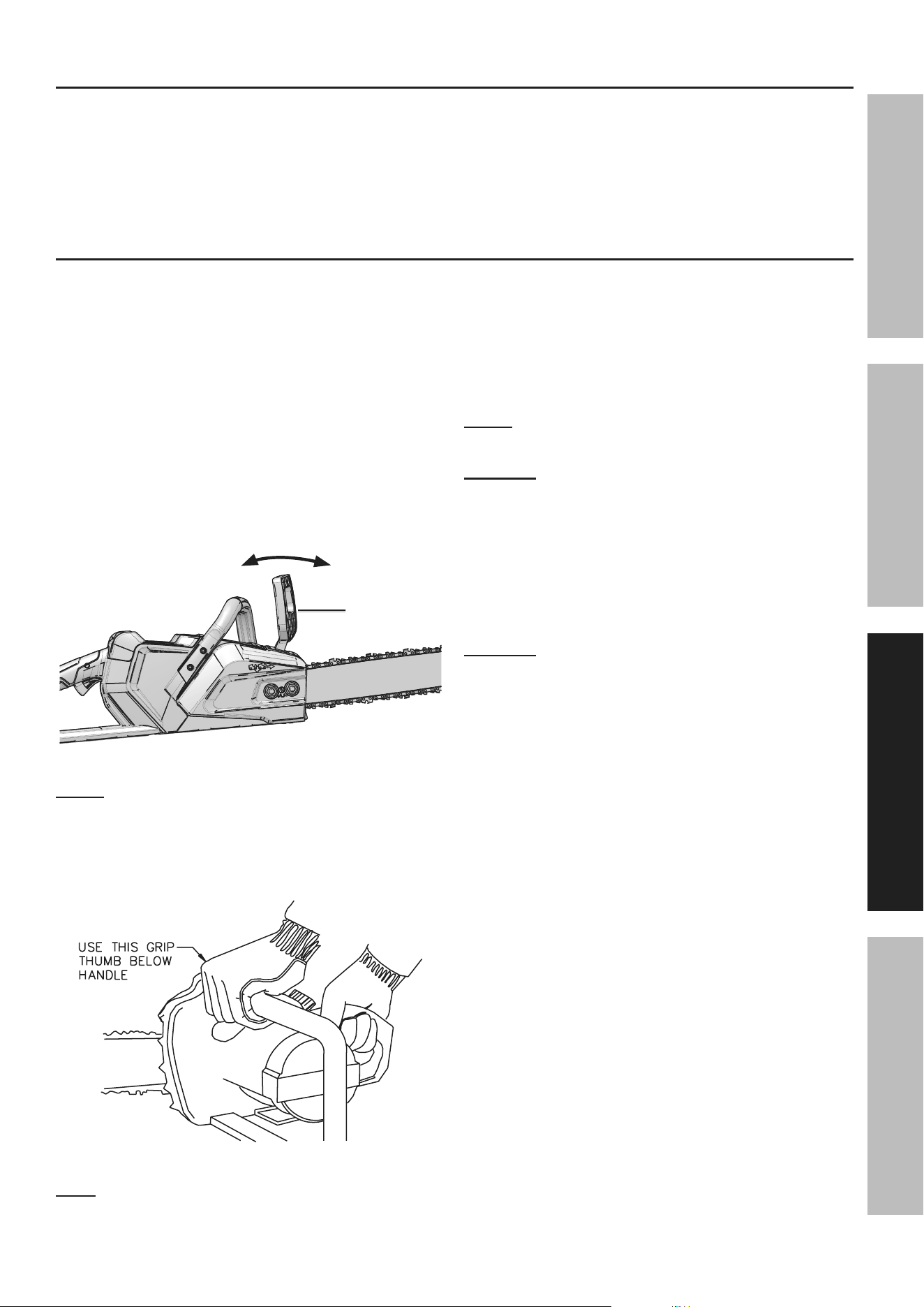
a. Maintain a firm grip, with thumbs and
fingers encircling the chain saw handles,
with both hands on the saw and position
your body and arm to allow you to resist
kickback forces. Kickback forces can be
controlled by the operator, if proper precautions
are taken. Do not let go of the chain saw.
use this grip
thumb below
handle
Figure a: Holding the chain Saw
b. Do not overreach and do not cut above
shoulder height. This helps prevent
unintended tip contact and enables better control
of the chain saw in unexpected situations.
c. Only use replacement bars and
chains specified by the manufacturer.
Incorrect replacement bars and chains may
cause chain breakage and/or kickback.
d. Follow the manufacturer’s sharpening and
maintenance instructions for the saw chain.
Decreasing the depth gauge height
can lead to increased kickback.
Page 5For technical questions, please call 1-888-866-5797.Item 56938 56937
SaFEtyOpEratiOnMaintEnancE SEtup
15. Maintain labels and nameplates on the tool.
These carry important safety information.
If unreadable or missing, contact
Harbor Freight Tools for a replacement.
16. Avoid unintentional starting.
Prepare to begin work before turning on the tool.
17. Do not leave the tool unattended when the
Battery Pack is connected. Turn off the tool,
and remove the Battery Pack before leaving.
18. The battery Charger gets hot during use.
The Charger’s heat can build up to
unsafe levels and create a fire hazard if it
does not receive adequate ventilation,
due to an electrical fault, or if it is used in a
hot environment.
Do not place the Charger on a flammable surface.
Do not obstruct any vents on the Charger.
Especially avoid placing the charger on carpets
and rugs; they are not only flammable, but they
also obstruct vents under the charger.
Place the Charger on a stable, solid, nonflammable
surface (such as a stable metal workbench or
concrete floor) at least 1 foot away from all
flammable objects, such as drapes or walls. Keep a
fire extinguisher and a smoke detector in the area.
Frequently monitor the Charger and
Battery Pack while charging.
19. This product is not a toy.
Keep it out of reach of children.
20. The warnings, precautions, and instructions
discussed in this instruction manual cannot cover all
possible conditions and situations that may occur.
It must be understood by the operator that
common sense and caution are factors
which cannot be built into this product,
but must be supplied by the operator.
Battery tool use and care
1. Prevent unintentional starting. Ensure the
switch is in the off-position before connecting
to battery pack, picking up or carrying the
power tool. Carrying the power tool with your
finger on the switch or energizing power tool
that have the switch on invites accidents.
2. Disconnect the battery pack from the power
tool before making any adjustments, changing
accessories, or storing power tool. Such
preventive safety measures reduce the risk
of starting the power tool accidentally.
3. Recharge only with the charger specified by
the manufacturer. A charger that is suitable for
one type of battery pack may create a risk of
fire when used with another battery pack.
4. Use power tools only with specifically designated
battery packs. Use of any other battery
packs may create a risk of injury and fire.
5. When battery pack is not in use, keep it away
from other metal objects, like paper clips,
coins, keys, nails, screws or other small metal
objects, that can make a connection from
one terminal to another. Shorting the battery
terminals together may cause burns or a fire.
6. Under abusive conditions, liquid may be
ejected from the battery; avoid contact.
If contact accidentally occurs, flush with
water. If liquid contacts eyes, additionally
seek medical help. Liquid ejected from the
battery may cause irritation or burns.
7. Do not use a battery pack or power tool that is
damaged or modified. Damaged or modified
batteries may exhibit unpredictable behavior
resulting in fire, explosion or risk of injury.
8. Do not expose a battery pack or power tool to
fire or excessive temperature. Exposure to fire or
temperature above 265°F may cause explosion.
9. Follow all charging instructions and do not charge
the battery pack or power tool outside of the
temperature range specified in the instructions.
Charging improperly or at temperatures
outside of the specified range may damage
the battery and increase the risk of fire.
10. Have servicing performed by a qualified
repair person using only identical
replacement parts. This will ensure that the
safety of the product is maintained.
11. Do not modify or attempt to repair the power
tool or the battery pack except as indicated
in the instructions for use and care.
12. The battery Charger gets hot during use.
The Charger’s heat can build up to
unsafe levels and create a fire hazard if it
does not receive adequate ventilation,
due to an electrical fault, or if it is used in a
hot environment. Do not place the Charger on a
flammable surface. Do not obstruct any vents on
the Charger. Especially avoid placing the
charger on carpets and rugs; they are not only
flammable, but they also obstruct vents under
the charger. Place the Charger on a stable, solid,
nonflammable surface (such as a stable metal
workbench or concrete floor) at least 1 foot away
from all flammable objects, such as drapes or walls.
Keep a fire extinguisher and a smoke detector in the
area. Frequently monitor the Charger and
Battery Pack while charging.
Page 6 For technical questions, please call 1-888-866-5797. Item 56938 56937
SaFEty OpEratiOn MaintEnancESEtup
Lithium Battery Safety Warnings
LitHiuM BattEriES StOrE
a LarGE aMOunt OF EnErGy anD
WiLL VEnt FirE Or EXpLODE iF MiStrEatED:
1. Keep Battery
Pack dry.
2. DO nOt DO any OF tHE FOLLOWinG
tO tHE BattEry pacK:
a. Open,
b. Drop,
c. Short-circuit,
d. puncture,
e. incinerate, or
f. Expose to temperatures greater than 265°F.
3. Charge Battery Pack only according
to its Charger’s instructions.
4. Inspect Battery Pack before every use;
do not use or charge if damaged.
Vibration Safety
This tool vibrates during use.
Repeated or long-term exposure to vibration may
cause temporary or permanent physical injury,
particularly to the hands, arms and shoulders.
To reduce the risk of vibration-related injury:
1. Anyone using vibrating tools regularly or for
an extended period should first be examined
by a doctor and then have regular medical
check-ups to ensure medical problems are not
being caused or worsened from use. Pregnant
women or people who have impaired blood
circulation to the hand, past hand injuries,
nervous system disorders, diabetes, or
Raynaud’s Disease should not use this tool.
If you feel any symptoms related to vibration (such
as tingling, numbness, and white or blue fingers),
seek medical advice as soon as possible.
2. Do not smoke during use. Nicotine reduces
the blood supply to the hands and fingers,
increasing the risk of vibration-related injury.
3. Wear suitable gloves to reduce the
vibration effects on the user.
4. Use tools with the lowest vibration
when there is a choice.
5. Include vibration-free periods each day of work.
6. Grip tool as lightly as possible (while still keeping
safe control of it). Let the tool do the work.
7. To reduce vibration, maintain the tool as
explained in this manual. If any abnormal
vibration occurs, stop use immediately.
SaVE tHESE inStructiOnS.
Grounding
tO prEVEnt ELEctric SHOcK anD DEatH FrOM incOrrEct GrOunDinG:
check with a qualified electrician if you are in doubt as to whether the outlet is properly
grounded. Do not modify the power cord plug provided with the charger. Do not use the charger
if the power cord or plug is damaged. if damaged, have it repaired by a service facility before
use. if the plug will not fit the outlet, have a proper outlet installed by a qualified electrician.
Extension cords
note: Extension cords must not be used with this item’s Charger.
Page 7For technical questions, please call 1-888-866-5797.Item 56938 56937
SaFEtyOpEratiOnMaintEnancE SEtup
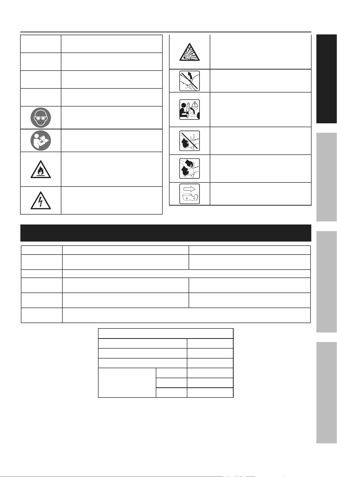
Symbology
V
Volts
Dc
Direct Current
a
Amperes
n
0
xxxx/min.
No Load Revolutions per Minute (RPM)
WARNING marking concerning Risk
of Eye Injury. Wear ANSI-approved
safety goggles with side shields.
Read the manual before
set-up and/or use.
WARNING marking
concerning Risk of Fire.
Do not cover Charger
ventilation ducts.
Charge on fireproof surface only.
WARNING marking concerning
Risk of Electric Shock.
Properly connect Charger’s power
cord to appropriate outlet.
WARNING marking concerning
Risk of Explosion.
Do not puncture, short, or open
battery packs and do not charge
damaged battery packs.
WARNING marking concerning Risk
of Kickback. Contact of the guide bar
tip with any object should be avoided.
WARNING marking concerning
Risk of Kickback. Tip contact
can cause the guide bar to move
suddenly upward and backward,
which can cause serious injury.
WARNING marking concerning
Risk of Loss of Control.
Do not operate the chainsaw
with only one hand.
WARNING marking concerning
Risk of Loss of Control.
Always use two hands when
operating the chainsaw.
WARNING marking concerning
Saw Chain Orientation. Cutters
must face in direction of rotation.
Specifications
MODEL
56938 56937
Battery Type
Atlas Li-Ion 40V (57008) or
40V/80V (57014) (sold separately)
Atlas Li-Ion 40V/80V (57014) (sold separately)
Charger Type 56993 or 56997 Atlas Li-ion (sold separately)
Guide Bar
16″ Sprocket Nose
Model: M1431656-1041TL
18″ Sprocket Nose
Model: M1501862-1041TL-2
Saw Chain
16″ Bar Length, 3/8″ Pitch, 0.043″ Gauge
Model: Trilink CL14356
18″ Bar Length, 3/8″ Pitch, 0.05″ Gauge
Model: Trilink CL15062
Lubrication
Bar and chain oil.
If not available, SAE 30W motor oil may be used.
ambient temperature ranges
Operation 6.8 - 104°F
Battery charging 39 - 104°F
Tool storage -4 - 158°F
Battery storage 1 year 32 - 73°F
3 month 32 -113°F
1 month 32 -140°F
Page 8 For technical questions, please call 1-888-866-5797. Item 56938 56937
SaFEty OpEratiOn MaintEnancESEtup
Setup - Before use:
read the EntirE iMpOrtant SaFEty inFOrMatiOn section at the beginning of this
manual including all text under subheadings therein before set up or use of this product.
note: For additional information regarding the parts listed in the following pages,
refer to Parts Lists and Diagrams on page 20.
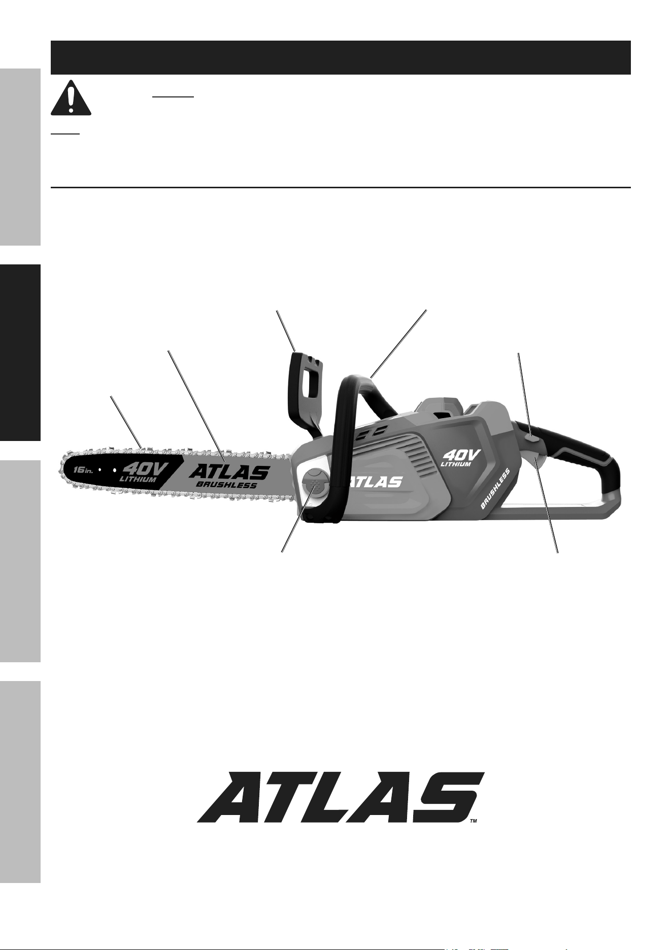
Functions
Oil tank cap
chain Guide Bar
Saw chain
Front Handle
trigger
Lockout
trigger
Hand Guard / chain Brake Lever

Page 9For technical questions, please call 1-888-866-5797.Item 56938 56937
SaFEtyOpEratiOnMaintEnancE SEtup
Safety Device Explanation
1. Hand Guard – A guard that protects your hand
on the Front Handle from the Saw Chain.
2. Chain Brake – A mechanical braking device
designed to quickly stop the Chainsaw and Chain
in the event of kickback. If kickback occurs, this
safety feature is activated when the operator’s
hand strikes the Hand Guard / Chain Brake Lever
and pushes it forward, stopping the Chain.
3. Trigger Lockout – A movable stop that
prevents the unintentional operation of
the Trigger until manually activated.
4. Low-Kickback Chain – A Chain that complies
with the kickback performance requirements
of ANSI B175.1-1991 when tested on a
representative sample of chainsaws.
Page 10 For technical questions, please call 1-888-866-5797. Item 56938 56937
SaFEty OpEratiOn MaintEnancESEtup
Guide Bar and Saw chain installation and adjustment
tO prEVEnt SEriOuS inJury FrOM acciDEntaL OpEratiOn:
Make sure that the trigger is in the off-position and remove the Battery
pack before performing any procedure in this section.
note: New Saw Chains often need to be tensioned several times during first use.
Check a new Saw Chain’s tension often when first using.
Follow the directions in the following sections for installing the Guide Bar and Saw Chain, for
checking and adjusting Saw Chain tension, and for replacing the Saw Chain when necessary.
Guide Bar / Saw chain installation/replacement
cautiOn! Wear heavy-duty work gloves when handling Saw chain.
1. BEFOrE FirSt uSE: Soak the Saw Chain
overnight in bar and chain oil (sold separately).
2. WarninG! to prevent serious injury
from accidental operation: remove the
Battery pack from the chainsaw.
3. Loosen and remove the Drive Cover Nuts,
then remove the Drive Cover from the Saw.
4. Place the Saw Chain over the Guide Bar.
The cutters of the Saw Chain must face
away from the Chainsaw along the top
edge of the Guide Bar. Fit the Drive Links
into the groove around the Guide Bar.
Guide Bar groove
5. Place the slotted end of the Chain Guide
Bar over the Guide Bar Bolts and insert
the Chain Tension Pin into the lower hole
in the Guide Bar. Refer to Figure B.
Sprocket
Guide Bar
Guide
Bar Bolts
chain tension pin
chain
Figure B: installing Guide Bar and chain
6. Place the Saw Chain over the Drive Sprocket.
Check again that the Saw Chain cutters are aligned
properly and the Saw Chain Drive Links are seated
completely in the slot of the Guide Bar. The
cutters of the Saw Chain must face away from the
Chainsaw along the top edge of the Guide Bar.
cuttErS MuSt FacE in
DirEctiOn OF rOtatiOn
tip of
Bar
cutter
Drive Link
cutters Depth Gauge
Drive Links
Direction of Saw
chain cutters
Saw
Guide Bar
nose
Figure c: Saw chain Orientation
7. Replace the Drive Cover and Drive Cover Nuts.
Tighten the Nuts so that the Cover is snug, but not
tight. Tension the Saw Chain following the steps
in Adjusting Saw Chain Tension on page 11.
Page 11For technical questions, please call 1-888-866-5797.Item 56938 56937
SaFEtyOpEratiOnMaintEnancE SEtup
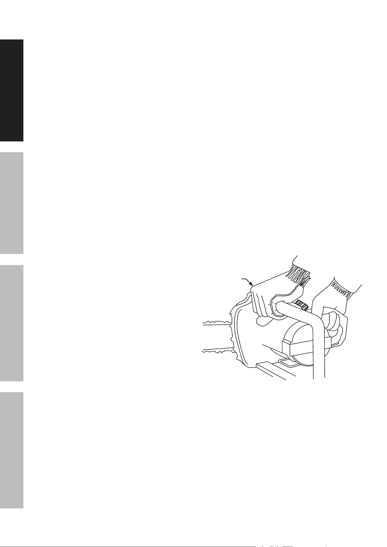
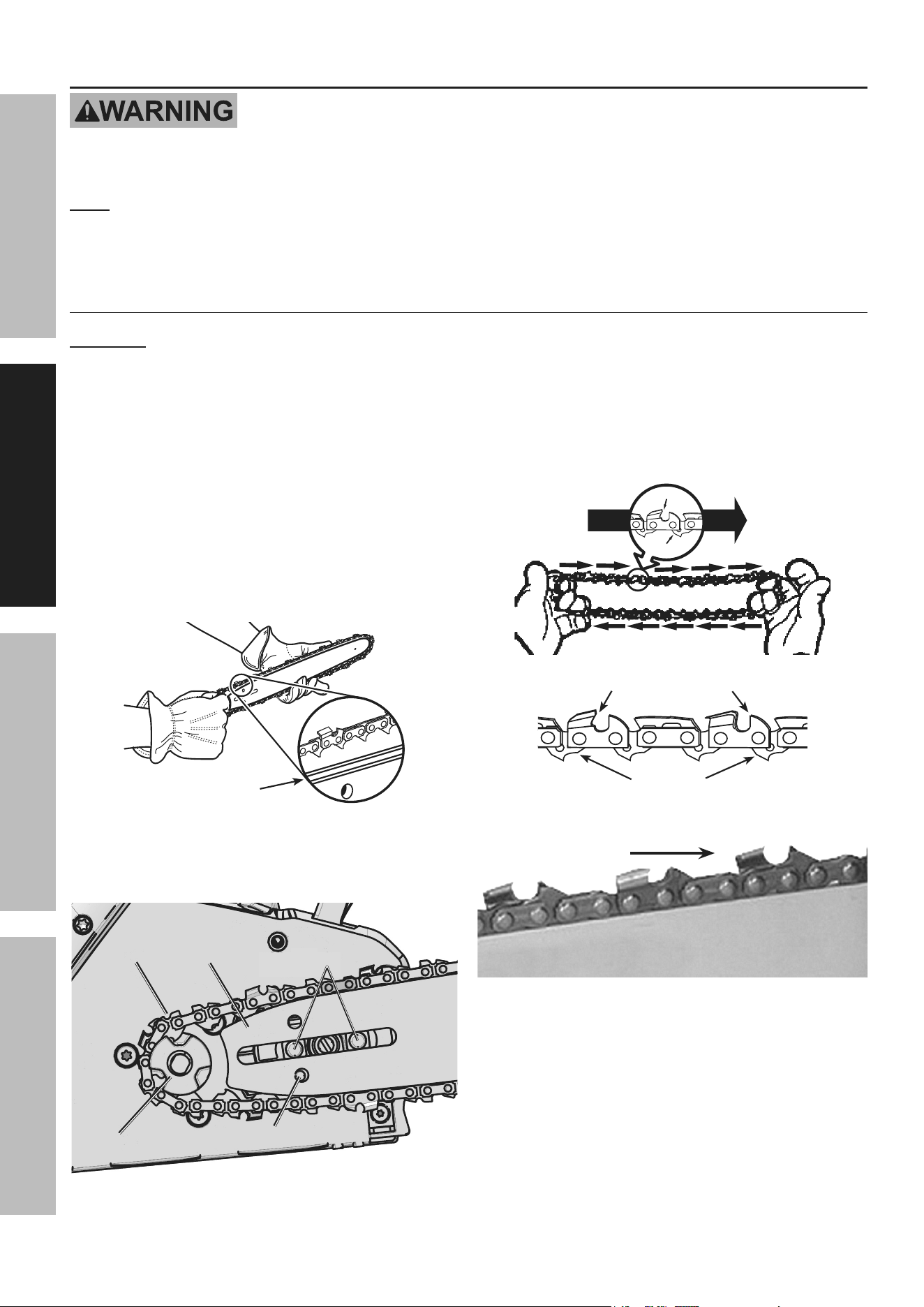
checking Saw chain tension
1. Before using, check the Saw Chain tension.
2. While wearing heavy-duty gloves, use your index
finger and thumb to carefully grab the Saw Chain
in the middle section under the Chain Guide Bar.
3. Pull the Saw Chain away from
the Guide Bar and let go.
4. The Saw Chain should snap back against
the Guide Bar. The Drive Links should fit
snugly in the groove of the Chain Guide Bar,
yet you should still be able to slide the Saw
Chain along the Guide Bar easily by hand.
5. There should be no sagging between the Guide
Bar and Saw Chain on the underside of the Guide
Bar, and Drive Links should not be visible.
note: Saw Chain tension should be checked
before and periodically during operation.
Guide Bar
Saw chain
(no Sagging)
(no Sagging)
Drive Link
Figure D: checking Saw chain tension
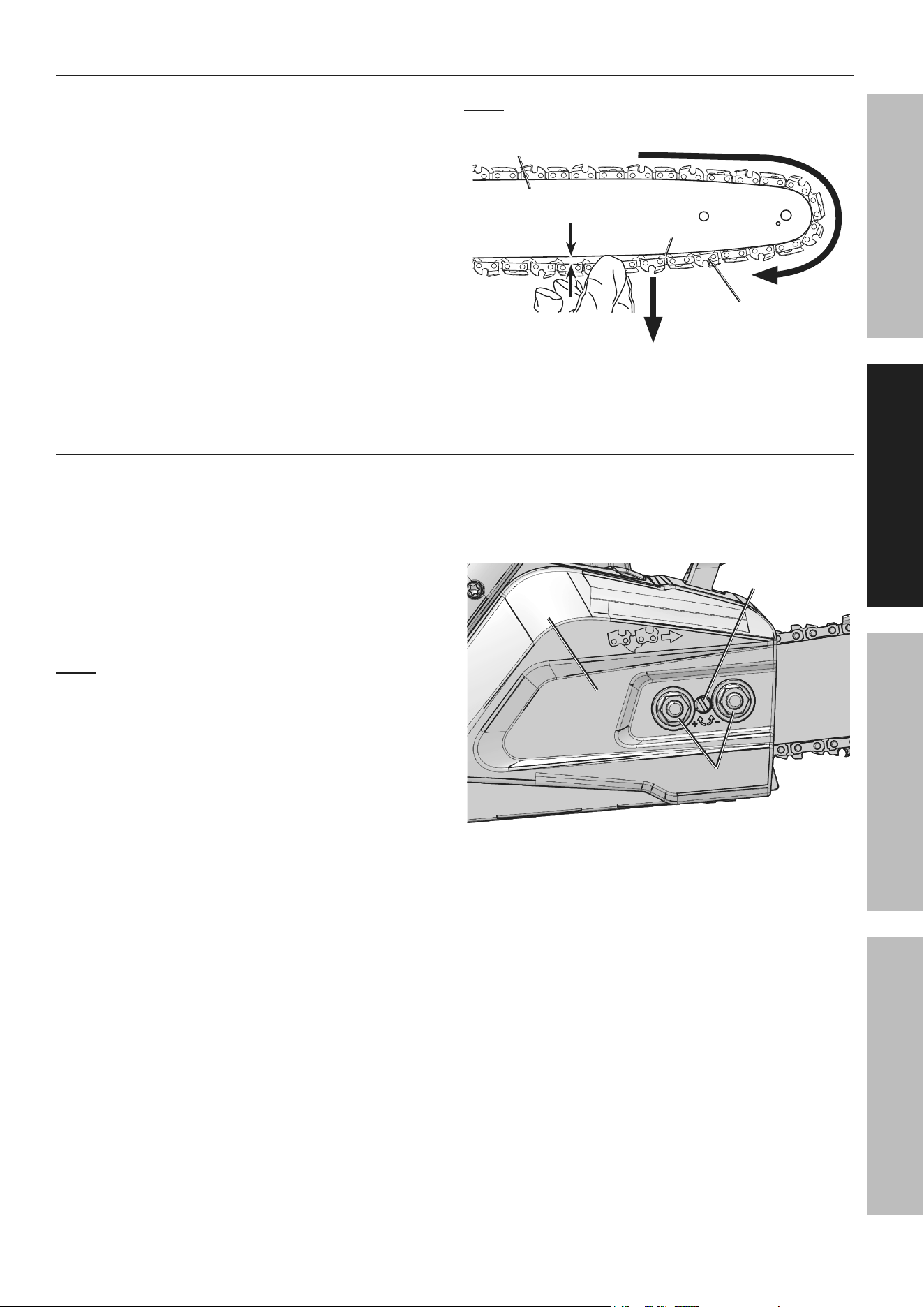
adjusting Saw chain tension
1. Loosen the Drive Cover Nuts on the Drive Cover. It
is not necessary to remove the Drive Cover to adjust
chain tension. Snug the Drive Cover Nuts just
enough to prevent side to side play in the Guide Bar.
2. Turn the Chain Tension Screw a couple of turns
counterclockwise to decrease tension; pull
the Saw Chain down until it sags slightly and
does not snap back against the Guide Bar.
note: Saw Chain tensioning should always be
done from low tension to proper tension.
3. While wearing heavy-duty gloves, carefully
grasp the Guide Bar and pull it upwards.
4. While holding the Guide Bar in its upward position,
Turn the Chain Tension Screw clockwise until
the Saw Chain is drawn upwards against the
Guide Bar and no Drive Links are visible.
5. Continue holding the Guide Bar in its
upward position and tighten the Drive
Cover Nuts on the Drive Cover.
6. Check the Saw Chain tension again following
steps 2 through 5 under Checking Saw Chain
Tension above. If needed, repeat the adjusting
steps to achieve the correct tension.
chain tension
Screw
Drive
cover
Drive
Drive
cover
cover
nuts
nuts
Figure E: adjusting Saw chain tension
Page 12 For technical questions, please call 1-888-866-5797. Item 56938 56937
SaFEty OpEratiOn MaintEnancESEtup
Operating instructions
read the EntirE iMpOrtant SaFEty inFOrMatiOn section at the beginning of this
manual including all text under subheadings therein before set up or use of this product.
charging Battery pack
Charge Battery Pack before using this tool.
Follow instructions included with Battery Charger
(both sold separately).
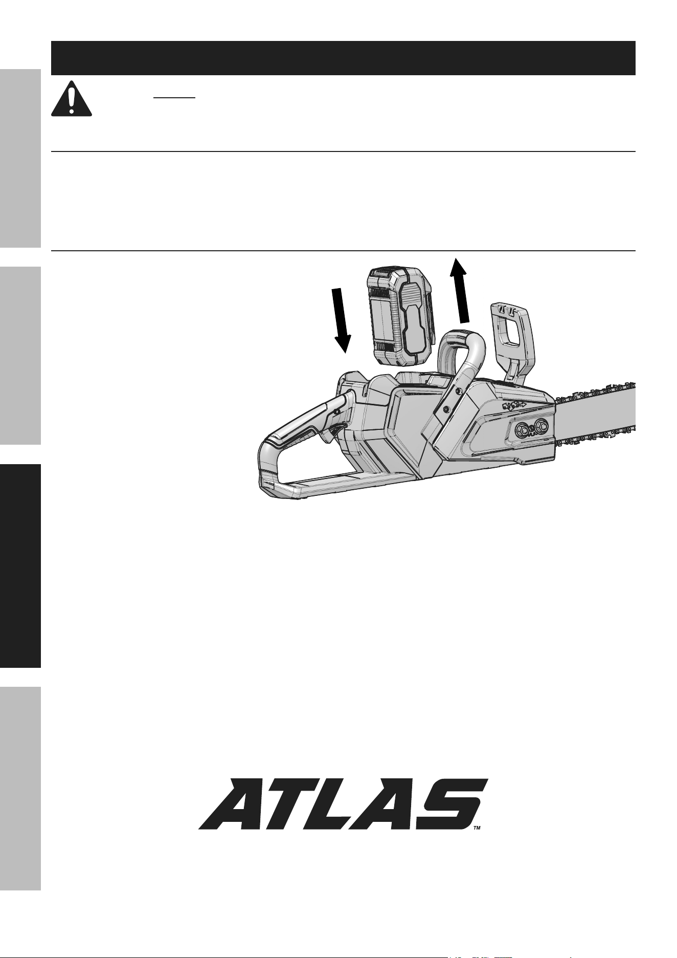
installing and removing Battery pack
1. To install: Slide Battery Pack into
battery compartment on top of
Chainsaw until it clicks into place.
2. To remove: Press the Battery Pack
Release Button and pull Battery
Pack out of battery compartment.
Figure F:
installing / removing Battery pack
Page 13For technical questions, please call 1-888-866-5797.Item 56938 56937
SaFEtyOpEratiOnMaintEnancE SEtup
Workpiece and Work area Set up
1. Designate a work area that is clean and well lit.
The work area must not allow access by children
or pets to prevent distraction and injury.
2. There must not be objects, such as utility lines,
nearby that will present a hazard while working.
3. A first-time user should, as a minimum practice,
cut logs on a saw-horse or cradle
before cutting down trees.
General Operating instructions
1. Before first use and before each use thereafter,
remove the Oil Tank Cap. Inspect the Cap Gasket
for damage. Fill the oil reservoir to just below fill
plug with oil (not included). Refer to Specifications
Chart on page 7 for oil type. Then replace
the Oil Tank Cap. Oil is automatically applied
to the Saw Chain during operation.
2. Make sure that the Trigger is in the off-position, then
slide the Battery Pack into battery compartment
on top of Chainsaw until it clicks into place.
3. Place the Hand Guard / Chain Brake Lever in normal
operating (disengaged) position by pulling the Hand
Guard back toward the Handle. Refer to Figure G.
D I S E N GAG E D E N GAGE D
Hand Guard /
chain Brake
Lever
Figure G: chain Brake
nOtE: The Chainsaw will not operate unless the Hand
Guard / Chain Brake Lever is in the disengaged position.
4. Grasp the Handles with both hands. Always grip
the handle with the thumb and fingers
encircling the handle as shown in Figure H.
Figure H: Holding the chainsaw
note: Front Hand Guard not shown.
5. Stand in front of the wood to be cut
with your feet firmly in place.
6. Push the Trigger Lockout Switch in, then squeeze
and hold the Trigger. With the Chainsaw running,
you may release pressure on the Lockout Switch.
Releasing the Trigger will stop the motor.
nOtE: The Trigger cannot be activated unless
the Trigger Lockout Switch is depressed.
DanGEr! To prevent serious injury and
death from kickback: Do not touch the
Guide Bar Nose to the wood.
7. When the Chainsaw reaches full speed, begin
cutting with a light, downward pressure against
the bottom mid-section of the Saw Chain.
Allow the Saw Chain to cut at its own rate.
Applying too much pressure can damage the tool.
DanGEr! When cutting loose, round wood stock,
place the wood stock on a sawhorse, in a cradle,
or use a timberjack (all sold separately)
to avoid grabbing and throw back.
8. To prevent accidents, turn off the tool,
remove its Battery Pack, and place the
Hand Guard / Chain Brake Lever forward
in its engaged position after use.
9. When the Saw has cooled completely,
clean thoroughly and cover the Chain
Guide Bar with the Chain Guide Bar Sheath.
Store the tool indoors out of children’s reach.
Page 14 For technical questions, please call 1-888-866-5797. Item 56938 56937
SaFEty OpEratiOn MaintEnancESEtup
instructions concerning the proper techniques for
basic felling, limbing, and cross-cutting
Felling a tree
When bucking and felling operations are being
performed by two or more persons at the same time,
the felling operations should be separated from the
bucking operation by a distance of at least twice the
height of the tree being felled. Trees should not be
felled in a manner that would endanger any person,
strike any utility line or cause any property damage.
If the tree does make contact with any utility line,
the company should be notified immediately.
The chainsaw operator should keep on the
uphill side of the terrain as the tree is likely
to roll or slide downhill after it is felled.
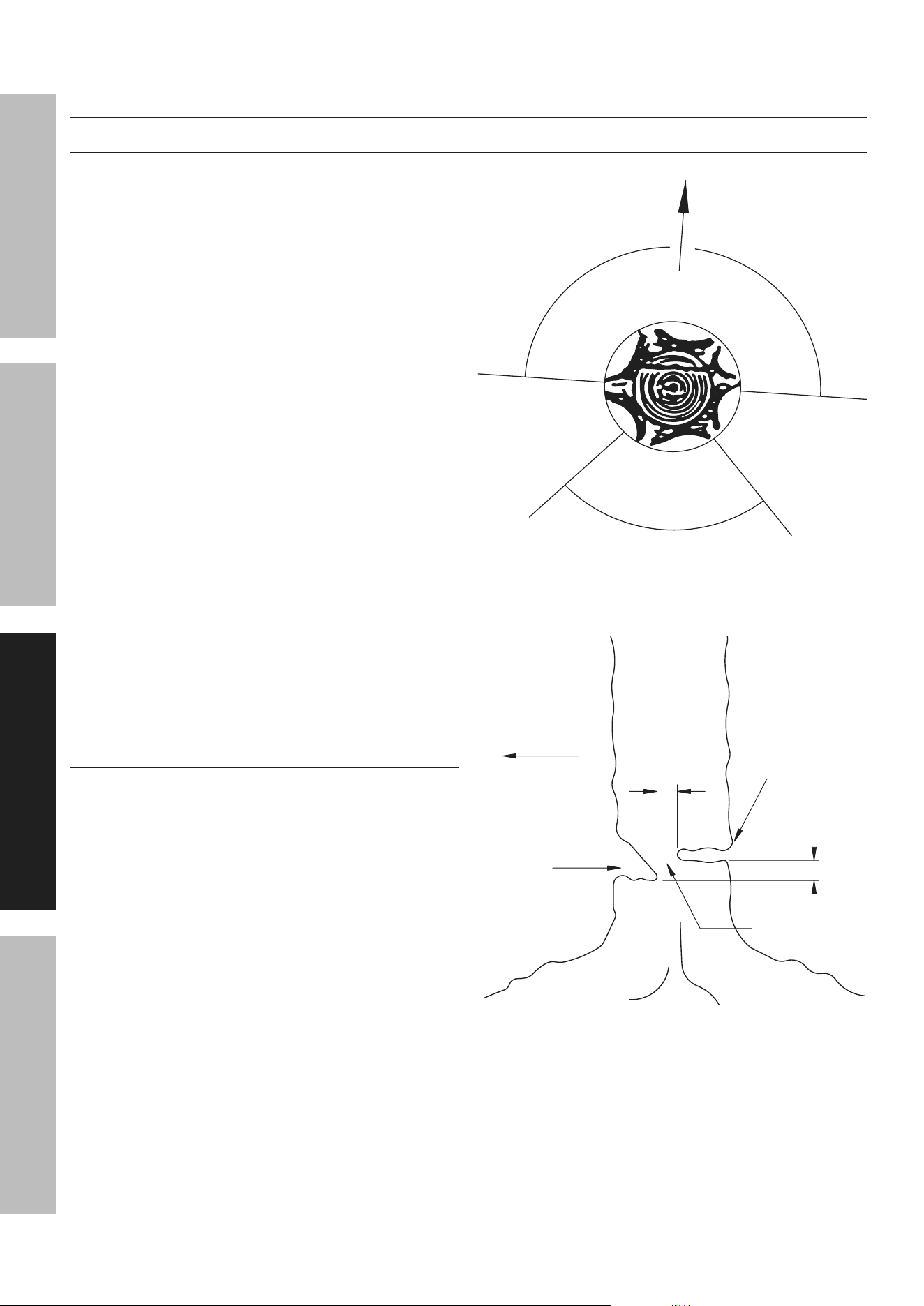
An escape path should be planned and cleared as
necessary before cuts are started. The escape path
should extend back and diagonally to the rear of
the expected line of fall as illustrated in Figure I.
Before felling is started, consider the natural lean
of the tree, the location of larger branches and the
wind direction to judge which way the tree will fall.
Remove dirt, stones, loose bark, nails,
staples and wire from the tree.
Felling Direction
Danger Zone
Danger Zone
Escape
route
Escape
route
Figure i: Escape routes
notching undercut
Make the notch 1/3 the diameter of the tree,
perpendicular to the direction of falls as illustrated in
Figure J. Make the lower horizontal notching cut first.
This will help to avoid pinching either the saw chain or
the guide bar when the second notch is being made.
Felling Back cut
Make the felling back cut at least 2 inches higher
than the horizontal notching cut as illustrated in
Figure J. Keep the felling back cut parallel to the
horizontal notching cut. Make the felling back cut
so enough wood is left to act as a hinge. The hinge
wood keeps the tree from twisting and falling in the
wrong direction. Do not cut through the hinge.
As the felling gets close to the hinge, the tree
should begin to fall. If there is any chance that the
tree may not fall in desired direction or it may rock
back and bind the saw chain, stop cutting before
the felling back cut is complete and use wedges
of wood, plastic or aluminium to open the cut and
drop the tree along the desired line of fall.
When the tree begins to fall remove the chainsaw
from the cut, stop the motor, put the chainsaw
down, then use the retreat path planned. Be alert
for overhead limbs falling and watch your footing.
Direction of Fall
2"
2"
Felling Back cut
Hinge
notch
Figure J: undercutting
Page 15For technical questions, please call 1-888-866-5797.Item 56938 56937
SaFEtyOpEratiOnMaintEnancE SEtup
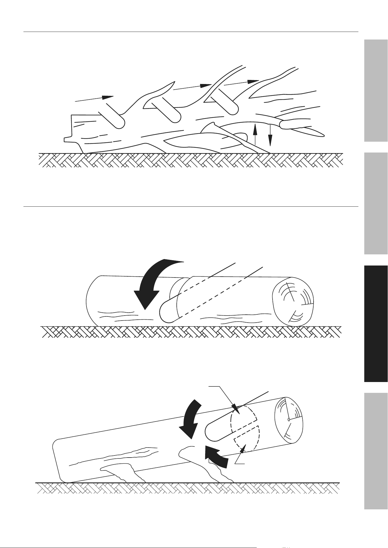
Limbing a tree
Limbing is removing the branches from a fallen tree. When limbing leave larger lower limbs
to support the log off the ground. Remove the small limbs in one cut as illustrated in Figure K.
Branches under tension should be cut from the bottom up to avoid binding the chainsaw.
Limb cut
Keep work off ground leave support limbs until log is cut
Figure K: tree Limbing
Bucking a Log
Bucking is cutting a log into lengths. It is important to make sure your footing is firm and your
weight is evenly distributed on both feet. When possible, the log should be raised and supported
by the use of limbs, logs or chocks. Follow the simple directions for easy cutting.
When the log is supported along its entire length as illustrated in Figure L, it is cut from the top (overbuck).
cut from top (overbuck) avoid cutting earth
Figure L: Log Supported along the Entire Length
When the log is supported on one end, as illustrated in Figure M, cut 1/3 the diameter from the
underside (underbuck). Then make the finished cut by overbucking to meet the first cut.
2
nd
cut overbuck (2/3 diameter)
to meet 1
st
cut (to avoid pinching)
1
st
cut underbuck (1/3 diameter)
to avoid splintering
Figure M: Log Supported One End
Page 16 For technical questions, please call 1-888-866-5797. Item 56938 56937
SaFEty OpEratiOn MaintEnancESEtup
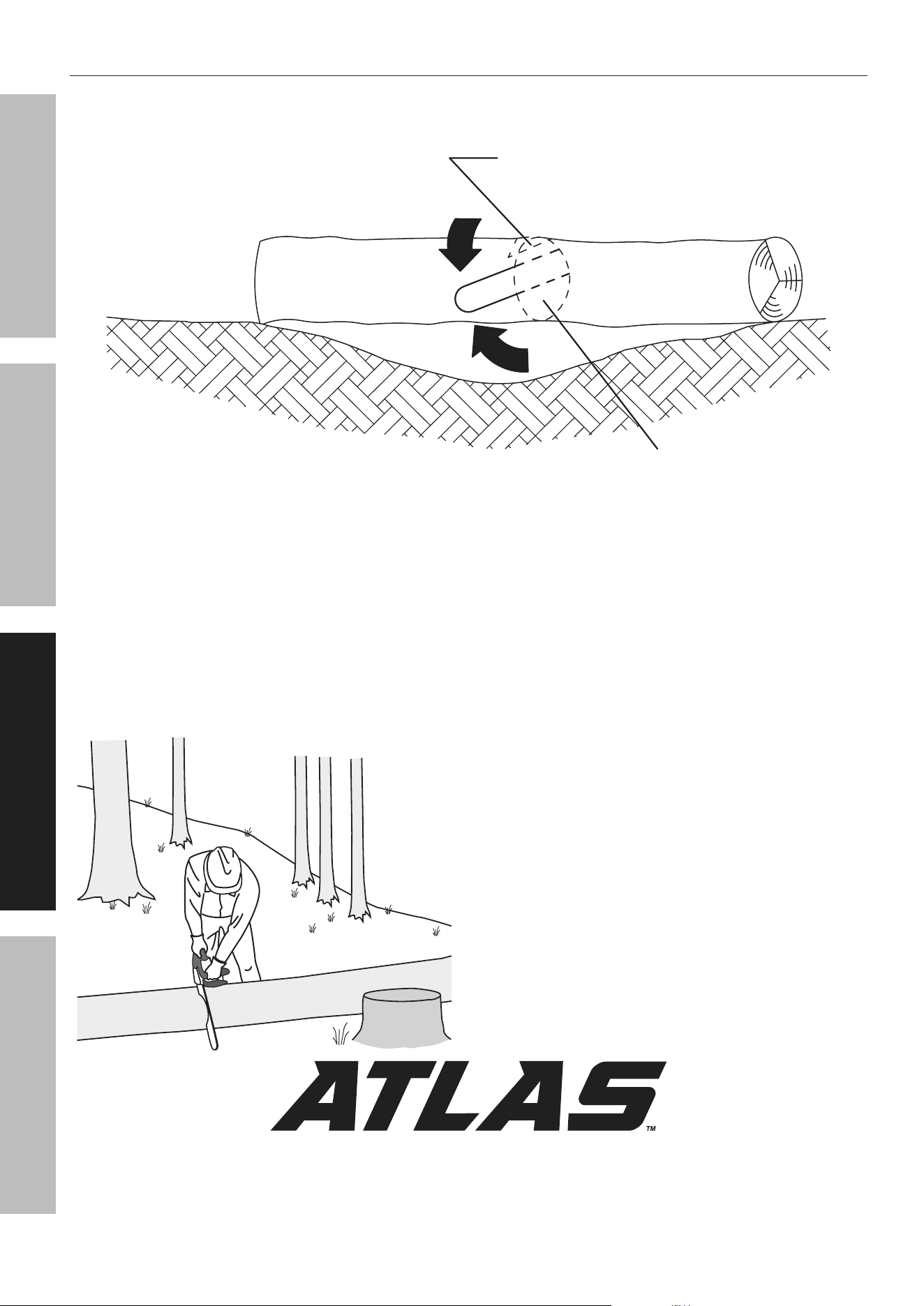
Bucking a Log (continued)
When the log is supported on both ends, as illustrated in Figure N, cut 1/3 the diameter from the top (overbuck).
Then make the finished cut by underbucking the lower 2/3 to meet the first cut.
2
nd
cut underbuck (2/3 diameter)
to meet 1
st
cut (to avoid pinching)
1
st
cut overbuck (1/3 diameter)
to avoid splintering
Figure n: Log Supported Both Ends
When bucking on a slope always stand on the
uphill side of the log, as illustrated in Figure O.
When “cutting through”, to maintain complete
control release the cutting pressure near the end of
the cut without relaxing your grip on the chainsaw
handles. Don’t let the chain contact the ground.
After completing the cut, wait for the saw chain to
stop before you move the chainsaw. Always stop
the motor before moving from tree to tree.
Stand on uphill side when cutting
because log may roll
Figure O: Bucking a Log

Page 17For technical questions, please call 1-888-866-5797.Item 56938 56937
SaFEtyOpEratiOnMaintEnancE SEtup
Maintenance and Servicing
procedures not specifically explained in this manual must
be performed only by a qualified technician.
tO prEVEnt SEriOuS inJury FrOM acciDEntaL OpEratiOn: Make sure that the trigger is in
the off-position and remove the Battery pack before performing any procedure in this section.
tO prEVEnt SEriOuS inJury FrOM tOOL FaiLurE: Do not use damaged equipment.
if abnormal noise or vibration occurs, have the problem corrected before further use.
cleaning, Maintenance, and Lubrication
1. BEFOrE EacH uSE, inspect the general
condition of the tool. Check for:
• leaking, swollen, or cracked battery pack
• loose hardware
• misalignment or binding of moving parts
• cracked or broken parts
• dull or damaged saw chain
• any other condition that may
affect its safe operation.
2. BEFOrE FirSt uSE anD BEFOrE EacH
uSE tHErEaFtEr, make sure the Oil Tank
is filled with oil (not included). Refer to
Specifications Chart on page 7 for oil type.
3. iF tHE SaW cHain BEcOMES LOOSE, adjust
the Saw Chain tension as described under
Adjusting Saw Chain Tension on page 11.
4. pEriODicaLLy Or WHEn rEpLacinG SaW
cHain, turn the Chain Guide Bar over to distribute
the wear on it. Replace the Guide Bar when bent,
cracked, or when the Saw Chain moves excessively
from side to side on the Guide Bar due to wear.
Refer to Chain Guide Bar Care on page 18.
WarninG! replace the Saw chain and Guide Bar
only with an identical Saw chain and Guide Bar.
5. aFtEr uSE, wipe the outside surface
of the Chainsaw with a clean, dry cloth.
If necessary use a mild detergent. Do not use
solvents. Do not immerse this tool in liquid.
6. Li-Ion BATTERY MUST BE RECYCLED OR
DISPOSED OF PROPERLY.
Do not short, incinerate or open battery.
7. Disconnect Battery Pack and store Battery
Pack, Charger, and tool in dry, indoor area out of
reach of children and away from metal objects
(i.e., paperclips, coins) to prevent shorting.
8. For long term storage or if storing
Chainsaw in a vertical position, remove
all residual oil from the oil reservoir.
Sharpening/replacing the Saw chain
WarninG! Wear heavy-duty work gloves when handling the Saw chain.
1. For smooth and safe operation,
always keep the Saw Chain cutters sharp.
2. Have the cutters sharpened by a qualified technician
when you notice any of the following symptoms:
a. The sawdust becomes powder-like.
b. You can’t make the cut without extra force.
c. The Chainsaw does not cut straight.
d. Vibration increases.
3. A Saw Chain that is damaged or too worn to be
restored to a usable condition by sharpening will
need to be replaced. Refer to Guide Bar / Saw Chain
Installation/Replacement on page 10.
WarninG! replace the Saw chain
only with an identical Saw chain.
Page 18 For technical questions, please call 1-888-866-5797. Item 56938 56937
SaFEty OpEratiOn MaintEnancESEtup
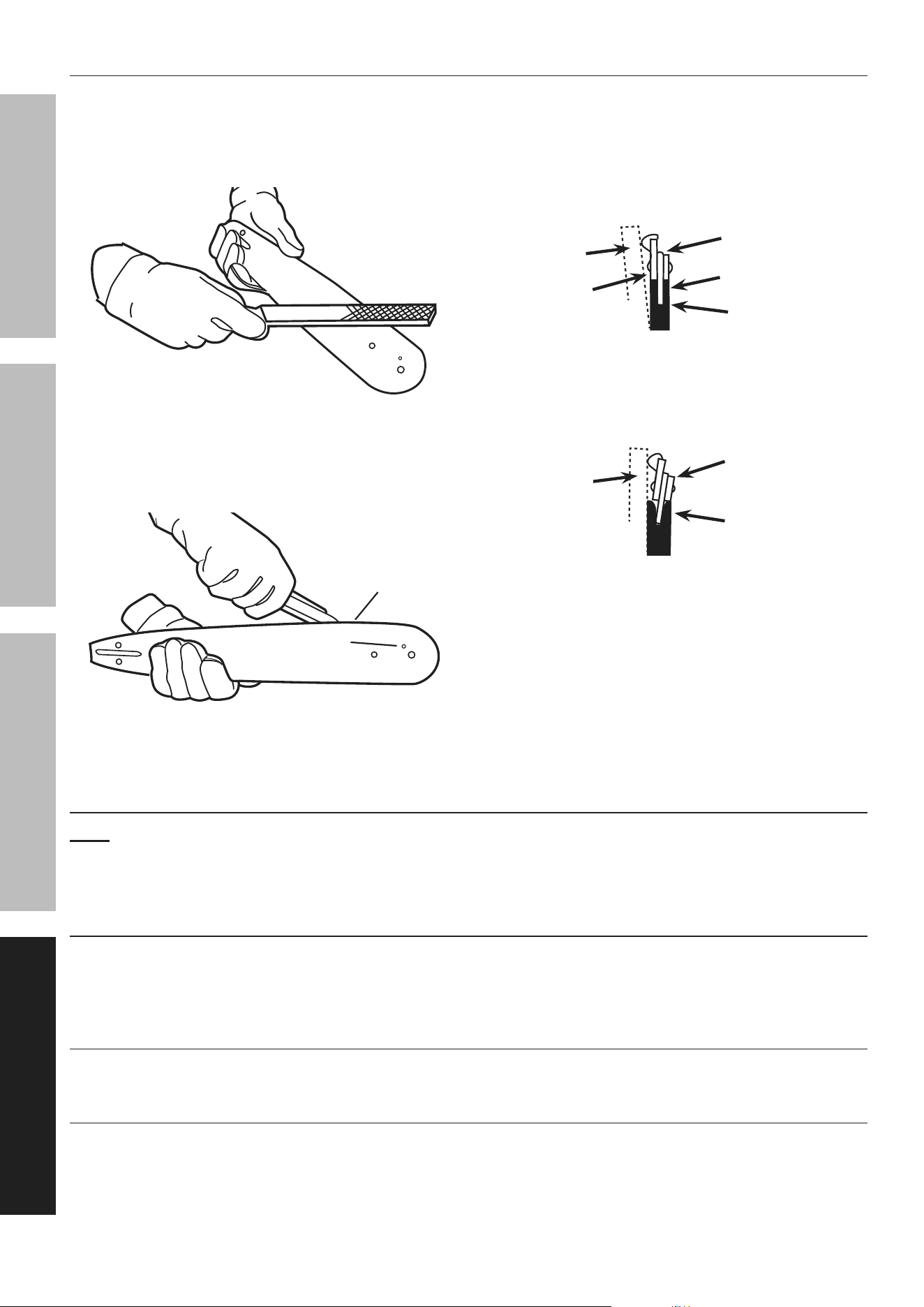
chain Guide Bar care
1. Remove the Chain Guide Bar
periodically to clean and lubricate.
2. Deburr rails of Guide Bar as needed.
Use a flat file to make side edges square.
Figure p: Deburring Guide Bar
3. Remove sawdust and sap from the
Bar Groove using a Guide Bar cleaning
tool (sold separately), then lubricate the
nose sprocket at the ports with grease.
Groove
Grease port
Figure Q: cleaning and Lubricating Guide Bar
4. Reverse the Guide Bar when replacing the
Saw Chain to prevent uneven wear.
5. The rails of the Guide Bar groove should
always be parallel to each other. Place a
ruler along the surface of the Guide Bar and
Saw Chain. If there is a gap, the bar is normal.
Straight
Guide Bar
ruler
rail
Saw
chain
Gap
Figure r: normal Guide Bar
If the ruler is flush with the Guide Bar and
Saw Chain, or the Chain tilts to one side, then
the Bar is worn and needs to be replaced.
ruler
Worn
Guide Bar
tilting Saw
chain
Figure S: Worn Guide Bar
cleaning, Maintenance, and Lubrication Schedule
note: This maintenance schedule is intended solely as a general guide. If performance decreases or if equipment
operates unusually, check systems immediately. The maintenance needs of each piece of equipment will differ
depending on factors such as duty cycle, temperature, air quality, and other factors. If you have doubts about your
ability to safely service this tool, have a qualified technician service the equipment instead.
periodic Maintenance or When replacing Saw chain:
a. Clean and lubricate Chain
Guide Bar and turn over.
b. Deburr Guide Bar as needed.
c. Check Chain Sprocket for wear or damage.
Monthly Maintenance:
Clean Chain Oil Tank.
if Worn or Damaged:
a. Replace Chain Guide Bar if it becomes
worn, bent or damaged.
b. Sharpen or replace Saw Chain.

Page 19For technical questions, please call 1-888-866-5797.Item 56938 56937
SaFEtyOpEratiOnMaintEnancE SEtup
troubleshooting
problem possible causes Likely Solutions
Tool will not start. 1. Battery Pack not properly
connected.
2. Battery Pack not properly charged.
3. Battery Pack burnt-out.
4. The Chain Brake Lever is engaged.
5. Internal damage or wear.
1. Remove Battery Pack, make sure
there are no obstructions, reinsert the
Battery Pack and press firmly until
the Battery Pack locks in place.
2. Make sure Charger is connected and
operating properly. Give enough time
for Battery Pack to recharge properly.
3. Dispose of old Battery Pack
properly or recycle. Replace Battery Pack.
4. Disengage the Chain Brake Lever.
5. Have qualified technician service tool.
Motor runs, but Chain
does not rotate.
1. Chain tension too tight.
2. Guide Bar and/or Chain damaged.
3. Gear train failure.
1. Adjust Saw Chain tension.
2. Inspect Guide Bar and Chain for damage.
Replace Guide Bar and Chain if necessary.
3. Have qualified technician service tool.
Motor runs, Chain
rotates but does not
cut or cuts poorly.
1. Saw Chain not tensioned properly.
2. Saw Chain dull.
3. Saw Chain installed backwards.
1. Tension Saw Chain properly.
2. Sharpen Saw Chain or replace.
3. Reverse direction of Saw Chain.
Chain comes off
Guide Bar.
1. Chain tension too loose.
2. Guide Bar and Chain not
installed correctly.
1. Adjust Saw Chain tension.
2. Review and correct Guide Bar
and Chain installation.
Guide Bar and Chain
running hot and smoking.
1. Chain tension too tight.
2. Oil Tank empty.
1. Adjust Saw Chain tension.
2. Check/refill Oil Tank.
Chainsaw stops
while cutting.
Forcing tool to work too
fast causing overload.
Release Trigger to reset internal circuit
breaker. Allow tool to work at its own rate.
Follow all safety precautions whenever diagnosing or servicing the tool.
Disconnect power supply before service.

Page 20 For technical questions, please call 1-888-866-5797. Item 56938 56937
SaFEty OpEratiOn MaintEnancESEtup
part Description Qty
1 Snap Ring 2
2 Sleeve 2
3 Drive Cover 1
4 Nut 2
5 Oil Gasket 1
6 Dustproof Cover 1
7 Sprocket Gasket 1
8 Brake Disc 1
9 Worm Gear 1
10 Worm 1
11 Shaft Sleeve 1
12 Oil Outlet Pipe 1
13 Brake Band 1
14 Screw St4.2 x 12 1
15 Brake Extension Spring 1
16 Connecting Bracket 1
17 Brake Hinge 1
18 Hand Guard 1
19 Screw M6 x 16 3
20 Right Housing 1
21 Trigger 1
22 Variable Speed Switch 1
23 Compression Spring 1
24 Trigger Lockout 1
25 Top Housing 1
26 Rocker Switch 1
27 Cross Recessed Pan Head Screw 1
28 Motor 1
part Description Qty
29 Compression Spring 2
30 Spring Base 1
31 PCBA 1
32 Left Housing 1
33 Front Handle Bracket 1
34 Flat Washer Φ5.2 x Ø15 x 1 1
35 Screw St4 x 14 29
36 Motor Cover 1
37 Front Handle 1
38 Screw St4.8 x 30 2
39 Lower Oil Tank Cover 1
40 Upper Oil Tank Cover 1
41 Oil Tank Cap 1
42 Filter Assembly 1
43 Oil Inlet Pipe 1
44 Saw Chain 1
45 Chain Guide Bar 1
46 Chain Guide Bar Sheath 1
47 Bucking Spike 1
48 Screw St4.2 x 14 3
49 Tension Assembly 1
50 Spring 1
51 Shaft Sleeve 1
52 Retaining Ring 1
53 Oil Pump Assembly 1
54 Circlip 1
55 Chain Retaining Bracket 1
56 Wrench 1
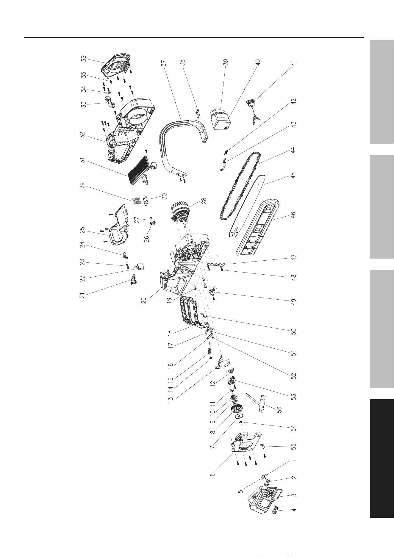
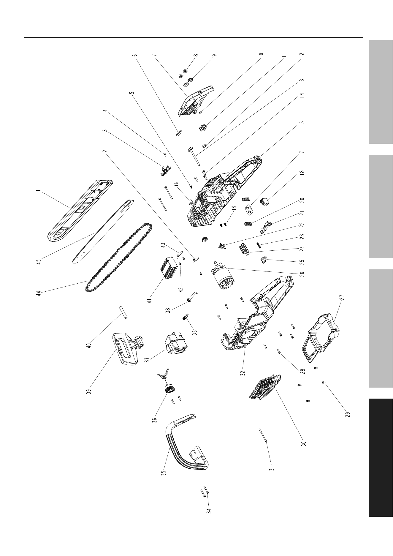
parts Lists and Diagrams
pLEaSE rEaD tHE FOLLOWinG carEFuLLy
THE MANUFACTURER AND/OR DISTRIBUTOR HAS PROVIDED THE PARTS LIST AND ASSEMBLY DIAGRAM
IN THIS MANUAL AS A REFERENCE TOOL ONLY. NEITHER THE MANUFACTURER OR DISTRIBUTOR
MAKES ANY REPRESENTATION OR WARRANTY OF ANY KIND TO THE BUYER THAT HE OR SHE IS
QUALIFIED TO MAKE ANY REPAIRS TO THE PRODUCT, OR THAT HE OR SHE IS QUALIFIED TO REPLACE
ANY PARTS OF THE PRODUCT. IN FACT, THE MANUFACTURER AND/OR DISTRIBUTOR EXPRESSLY
STATES THAT ALL REPAIRS AND PARTS REPLACEMENTS SHOULD BE UNDERTAKEN BY CERTIFIED AND
LICENSED TECHNICIANS, AND NOT BY THE BUYER. THE BUYER ASSUMES ALL RISK AND LIABILITY
ARISING OUT OF HIS OR HER REPAIRS TO THE ORIGINAL PRODUCT OR REPLACEMENT PARTS
THERETO, OR ARISING OUT OF HIS OR HER INSTALLATION OF REPLACEMENT PARTS THERETO.
56937 parts List
record product’s Serial number Here:
note: if product has no serial number, record month and year of purchase instead.
Page 21For technical questions, please call 1-888-866-5797.Item 56938 56937
SaFEtyOpEratiOnMaintEnancE SEtup
56937 assembly Diagram

Page 22 For technical questions, please call 1-888-866-5797. Item 56938 56937
SaFEty OpEratiOn MaintEnancESEtup
part Description Qty
1 Chain Guide Bar Sheath 1
2 Signal Switch 1
3 Tension Assembly 1
4 Screw St4 x 10-F 1
5 Screw St4.2 x 16 1
6 Washer 1
7 Drive Cover 1
8 Nut 2
9 Bushing 2
10 The Metal Ring To Limit 1
11 Drive Sprocket 1
12 Spacer Bushing 1
13 Output Tube 1
14 Screw M6 x 16 3
15 Right Housing 1
16 Chain Retaining Bracket 1
17 Spring Base 1
18 Variable Speed Switch 1
19 Screw Assembly 2
20 Compression Spring 2
21 Trigger 1
22 Oil Pump Assembly 1
23 Compression Spring 1
part Description Qty
24 Battery Pack Connection Socket 1
25 Trigger Lockout 1
26 Motor 1
27 Top Cover 1
28 Screw St4.2 x 16 10
29 Screw St4.2 x 12 4
30 Motor Cover 1
31 Screw St4.8 x 60 3
32 Left Housing 1
33 Filter Assembly 1
34 Screw St4.8 x 30 2
35 Front Handle 1
36 Oil Tank Cap Assembly 1
37 Oil Tank Assembly 1
38 Input Tube 1
39 Handguard 1
40 Handguard Shaft 1
41 PCB 1
42 Screw St3 x 8 3
43 Leaf Spring 1
44 Saw Chain 1
45 Chain Guide Bar 1
56938 parts List
note: Some parts are listed and shown for illustration purposes only, and are not available individually
as replacement parts. Parts may not be interchangeable. Specify UPC number when ordering:
40 V: 792363569385
80 V: 193175453068
Page 23For technical questions, please call 1-888-866-5797.Item 56938 56937
SaFEtyOpEratiOnMaintEnancE SEtup
56938 assembly Diagram

26677 agoura road • calabasas, ca 91302 • 1-888-866-5797
Limited 90 Day Warranty
Harbor Freight Tools Co. makes every effort to assure that its products meet high quality and durability standards,
and warrants to the original purchaser that this product is free from defects in materials and workmanship for the
period of 90 days from the date of purchase. This warranty does not apply to damage due directly or indirectly,
to misuse, abuse, negligence or accidents, repairs or alterations outside our facilities, criminal activity, improper
installation, normal wear and tear, or to lack of maintenance. We shall in no event be liable for death, injuries
to persons or property, or for incidental, contingent, special or consequential damages arising from the use of
our product. Some states do not allow the exclusion or limitation of incidental or consequential damages, so the
above limitation of exclusion may not apply to you. THIS WARRANTY IS EXPRESSLY IN LIEU OF ALL OTHER
WARRANTIES, EXPRESS OR IMPLIED, INCLUDING THE WARRANTIES OF MERCHANTABILITY AND FITNESS.
To take advantage of this warranty, the product or part must be returned to us with transportation charges
prepaid. Proof of purchase date and an explanation of the complaint must accompany the merchandise.
If our inspection verifies the defect, we will either repair or replace the product at our election or we may
elect to refund the purchase price if we cannot readily and quickly provide you with a replacement. We will
return repaired products at our expense, but if we determine there is no defect, or that the defect resulted
from causes not within the scope of our warranty, then you must bear the cost of returning the product.
This warranty gives you specific legal rights and you may also have other rights which vary from state to state.