
Operator’s Manual
www. mechmaxx.com
WARRANTY


TABLE OF CONTENTS
TABLE OF CONTENTS
SPECIFICATIONS
SAFETY SIGNS
SAFETY INSTRUCTIONS
1
2
SAFETY FIRST
GENERAL SAFETY
OPERATING SAFETY
4
4
5
STORAGE SAFETY
5
MAINTENANCE SAFETY
5
BLADE MOUNTING
CONNECTING WITH THE THREE-POINT
LINkAGE OF TRACTOR
6
6
ADJUSTMENT BEFORE WORKING
6
STARTING OF THE TILLER
6
3
4
6
7
8
MAINTENANCE
STORAGE
LUBRICATION
8
8
8
OPERATION
SIZING PTO SHFAT
MAINTENANCE & LUBRICATION
9
PARTS DIAGRAM
10
PARTS LIST
1
www. mechmaxx.com
TABLE OF CONTENTS

SPECIFICATIONS
2
www. mechmaxx.com
SPECIFICATIONS
Power Required
Model
18-35HP 25-45HP 25-50HP 30-60HP
RT400 RT450 RT500 RT600
Working Width 48 in
Overall Width
57 in
53 in
60 in
60 in 72 in
66 in 78 in
Working Depth
1in,2.1in,3.1in,5.1in
Blade Type
Number Of Blades
Number Of Flanges
C type
30
6
36
7
42
8
Blade Material 60SI2MN
Rotor Bearing NSK bearing
Rotor Diameter 3in
Rotor Swing Diameter 19.5in
Rotor Thickness 0.3in
Rotor Shaft Speed 215 RPM
Rotor Rotation Forward
Drive Type Gear Drive
0.16in
SAE 85W-90
1:52:1
0.31in
540 RPM
T4-31in 8 Bolt non-removable slip clutch
1.375in X Z6
CAT 1 CAT 1/2 CAT 2
Rear Hinged
Powder Coating
57 X 31.5 X 30.7in 60 X 32 X 31 in 66 X 31.5 X 30.7 in 78 X 31.5 X 30.7 in
1 year
628 lbs 643 lbs
720 lbs 760 lbs
690 lbs
793 lbs
785 lbs
860 lbs
Main Gearbox
Drive Gear Ratio
Gearbox Oil Type
Deck Thickness
Side Plate Thickness
PTO Shaft RPM
PTO Shaft
Spline End
3-Point Hitch
Deflector
Finish
Dimensions (L x W x H)
Warranty
Net Weight
Gross Weight
ASAE 1- 3/8″ – 6 spline shaft, proven cast iron, oil bath gearbox; ratio is 1.69:1
3
www. mechmaxx.com
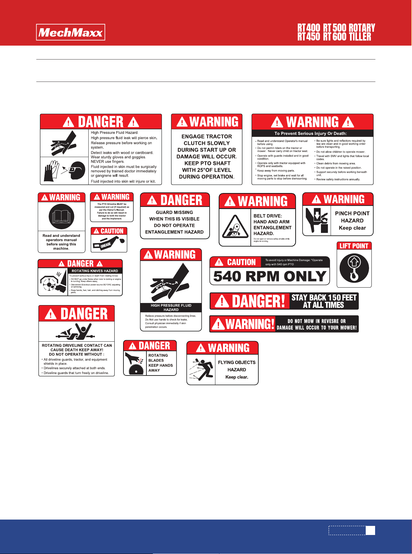
SAFETY SIGNS
The rating plate on your machine may show symbols. These represent important information about the product or instruc-
tions on its use.
SAFETY SIGNS

4
www. mechmaxx.com
SAFETY INSTRUCTIONS
SAFETY INSTRUCTIONS
CONGRATULATIONS! On the purchase of our Rotary hoe.
This information is to assist you in preparing, operating
and maintaining your Rotary hoe. Please read and under-
stand the information completely before operating your
Rotary hoe, paying special attention to all the safety
details. Keep this manual handy for a ready reference.
YOU are responsible for the SAFE operation and mainte-
nance of your Rotary hoe. YOU must ensure that you and
anyone else who is going to operate, maintain or work
around the Rotary Hoe is familiar with the operating and
maintenance procedures and related SAFETY information
contained in this manual. This manual will take you
step-by-step through your working day and alert you to all
good safety practices that should be adhered to while
operating the Rotary hoe.
Remember, YOU are the key to safety. Good safety
practices not only protect you but also the people around
you. Make these practices a working part of your safety
program. Be certain that EVERYONE operating this equip-
ment is familiar with the recommended operating and
maintenance procedures and follows all the safety
precautions. Most accidents can be prevented. Do not
risk injury of death by ignoring good safety practices.
1. Rotary hoe owners must give operating instructions to
operators or employees before allowing them to operate
the machine.
2. The most important safety feature on this equipment
is a SAFE operator. It is the operator’s responsibility to
read and understand ALL Safety and Operating instruc-
tions in the manual and to follow these. All accidents can
be avoided.
3. A person who has not read and understood all operat-
ing and safety instructions is not qualified to operate the
machine. An untrained operator jeopardise himself and
bystanders to possible serious injury or death.
1. Read the operator’s Manual and all safety signs careful-
ly before operating, maintaining, adjusting or removing the
Rotary hoe.
2. Do not allow passengers to ride on the Rotary hoe.
3.Operate only at safe distance from bystanders. Clear
the area of people, especially small children, before start-
ing.
4. Stop PTO before dismounting tractor
5. Keep feet and hands from under rotary hoe at all times.
6. Keep all shields in place. If shield removal becomes
necessary for repairs, replace the shield prior to use.
7. Do not stay between the tractor and the Rotary hoe.
8 .Do not approach the Rotary hoe until all motion has
stopped.
9. All rotary blades have the ability to discharge objects at
high speeds, which could result in serious injury to
bystanders or passers-by, use with extreme caution.
10. Place all controls in neutral, stop tractor engine, set
park brake, remove ignition key and wait for all moving
parts to stop before servicing, adjusting, repairing,
attaching or removing.
11. Review safety related items annually with all person-
nel who will operate or maintain the Rotary hoes.
12. Do not operate machine if you feel unwell or physically
unfit, in which case you should stop working.
13. This machine was designed with safety very much in
mind. However, there is no real substitute for caution and
attention in preventing accidents. Once an accident has
happened, it is too late to think about what you should
have done.
14. Use a tractor equipped with a Roll Over Protective
Structure (ROPS). Always wear your seat belt. Serious
injury or even death could result from falling off the
tractor – particularly during a turnover when the operator
could be pined under the ROPS or the tractor.
4. Do not modify the equipment in any way. Unauthorized
modification may weaken the function and/or safety and
could affect the life of the equipment.
5. Think SAFETY! Work SAFELY!
Before operating the Rotary Hoe, read the
following safety instructions.Failure to
comply with these warnings may result in
serious injury or death.
SAFETY FIRST
GENERAL SAFETY

5
www. mechmaxx.com
SAFETY INSTRUCTIONS
15. Never exceed the limits of a piece of machinery. If its
ability to do a job, or to do so safety, is in question –
DON’T TRY IT.
16. Clear working area of stones, branches or hidden
obstacles that might be hooked or snagged, causing
injury or damage.
1. Store the machine in an area away from human activity.
2. Do not permit children to play on or around the stored
machine.
3. Store the machine in a dry, level area.
4. Clean grease and oil as required and protect it from the
elements
1.Read and understand the Operator’s Manual and all
safety signs before operating, servicing, adjusting, repair-
ing or removing.
2.Do not allow riders
3.Install and secure all guards and shields before starting
or operating.
4.Keep hands, feet, hair and clothing away from moving
parts.
5.Place all controls in neutral, stop tractor engine, set
park brake, remove ignition key and wait for all moving
parts to stop before servicing, adjusting, repairing ,
attaching or removing.
6.Place all controls in neutral, stop tractor engine, set
park brake, remove ignition key and wait for all moving
parts to stop before servicing, adjusting, repairing ,
attaching or removing.
7.Never start or operate machine unless sitting on tractor
seat.
8.Clear the area of bystanders, especially small children,
before starting
9.Stay away from PTO shaft and machine when engaging
PTO. Keep others away.
10.Use warning lights on tractor when transporting.
11.Do not put hands or feet under machine while tractor
engine or machine is running.
12.Do not operate Rotary hoe in the raised position.
13.Objects can be thrown out from under machine with
sufficient force to severely injure people. Stay away from
machine when it is running. Keep others away.
14.Always know what you are hoeing. Never operate
Rotary hoe in an area that has hidden obstacles. Remove
sticks, stones, wire or other objects from working area
before starting.
15.Review safety instructions with all operators annually
1. Good maintenance is your responsibility. Poor mainte-
nance is an invitation to trouble.
2. Follow good shop practices.
3. Keep service area clean and dry.
4. Be sure electrical outlets and tools are properly ground-
ed.
5. Use adequate light for the job at hand.
6. Make sure there is plenty of ventilation. Never operate
the engine of the tractor in a closed building. The exhaust
fumes may cause asphyxiation.
7. Before working on this machine, shut off the engine,
set the brakes, and remove the ignition Key
8. Never work under equipment unless it is secured by a
mechanical stand.
9. Use personal protection devices such as eye, hand and
hearing protectors, when performing any service or main-
tenance work. Use heavy gloves when handling blades.
10. Only use genuine parts for service and maintenance.
11. Keep fire extinguisher and first aid kit in an easily
accessible place when performing maintenance on equip-
ment.
12. Periodically tighten all bolts, nuts and screws and
check that all pins are properly installed to ensure unit is
in a safe condition.
13. When completing a maintenance or service function,
make sure all safety shields and devices are installed
before placing machine in service.
OPERATING SAFETY
STORAGE SAFETY
MAINTENANCE SAFETY

6
www. mechmaxx.com
OPERATION
OPERATION
Each rotary hoe has the same number of left and right
blades. The outer flanges have three blade end turned
inwards. The inner flange carry six blades consists of
three left and three right Make sure the front or sharpened
edge of the blades enter the soil first
The Rotary hoe is connected to the tractor by the
three-point linkage. Its installing step is as follows:
1. Align the center of headstock by reversing the tractor,
raise the link arm to appropriate height, reverse the
tractor to make the link arm of tractor joint with the left
and right pin of rotary tiller.
2. First install the left lower linkage arm, then install right
lower linkage arm, (because the leveling lift rod has screw
that can be adjusted length.) finally inert the pins.
3. Install the upper linkage arm, and then insert the pin.
4. Mount the universal coupling, and then insert the pins,
poke the cotter pin.
1. On a flat surface, lower the implement to the ground. If
not sitting level side to side, adjust the vertical linkage
arms on the three point linkage till the implement is
sitting level on the ground
2. Adjust the top link to reduce the angle at the PTO shaft
universal to the minimum at working depth. The angle of
the universal should not exceed 10º when it is working
and 30 º when it is lifted for transport. Do not engage and
operate the PTO at angle of greater then 10 º at the
universal
3. Adjust the working depth by setting the adjustable
skids to the required height
First, check the level of the gear oil in the gearbox and the
side chain box, grease the PTO Shaft and the bearing seat
of the blade shaft. Then check for the looseness of all
connecting bolts and nuts, if loose, tighten it at once. If a
crack or bent blades are found they must be replaced.
Starting tractor: Lift the hoe so the blades clear the
ground, engage the PTO and run at low revs to ensure
there is no jamming.
Soil penetration: Use PTO speed1(540RPM) & select low
creeper gear. Increase rev and lower the hoe gradually
until desired depth is met, then proceed forward.
BLADE MOUNTING
CONNECTING WITH THE THREE-POINT
LINkAGE OF TRACTOR
ADJUSTMENT BEFORE WORKING
STARTING OF THE TILLER
7
www. mechmaxx.com
SIZING PTO SHFAT
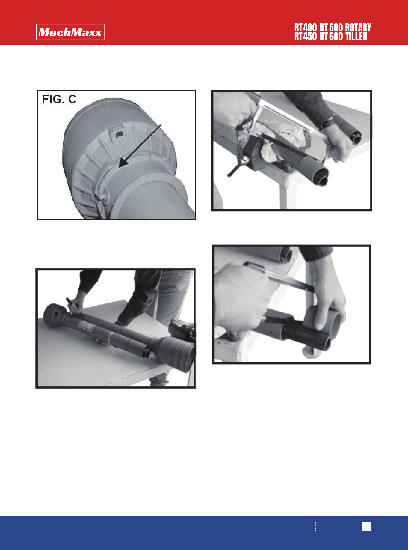
SIZING PTO SHFAT
STEP 1 Cutting the PTO shaft to length.
NOTE: Be sure to cut equal lengths of each PTO shaft
section. Clamp end of PTO shaft in a vice and cut off
shield where marked. (Figure 1-A & 1-B)
STEP 3 Repeat steps 1 and 2 for other PTO shaft section.
STEP 4 Use a file to deburr PTO shafts. Clean up all chips,
burrs and filings from both ends of the PTO shaft.
STEP 2 Using cut section of the shield as a guide cut
shaft off the same amount. (Figure 2)
Figure 1-A
Figure 1-B
Figure 2
8
www. mechmaxx.com
MAINTENANCE & LUBRICATION
MAINTENANCE & LUBRICATION
Proper servicing and adjustment is the key to the long life
of any implement. With careful inspection and routine
maintenance, you can avoid costly downtime and repair
the parts on your rotary tiller. Do not alter the tiller in a
way which will adversely affect its performance.
Check all bolts and pins after using the unit for several
hours and on a regular basis thereafter to ensure they are
tight and secured. Replace worn, damaged, or illegible
safety labels by obtaining new labels from the dealer.
Clean, inspect, service, and make necessary repairs to
the Rotary Tiller when parking it for long periods and when
parking it at the end of a working season. This will help
ensure that the tiller is ready for field use the next time
you hook-up to it.
1. Clean off any dirt and grease that may have accumulat-
ed on the Rotary Tiller. Scrape of compacted dirt and then
wash surfaces thoroughly with a garden hose.
2. Check the tines for wear and replace if necessary.
3. Inspect the tiller for loose, damaged or worn parts and
adjust or replace if needed.
4. Lubricate as noted in “Lubrication”
5. Drain and refill gearbox and Gear case oil. Be sure to
replace all oil plugs.Drain oil in gearbox by removing the
bottom drain plug or right-hand cap.Drain oil in Gear case
by removing the bottom plug and tipping tiller backwards.
6. Replace all damaged or missing decals.
7. Store tiller on a level surface in a clean, dry place.
Inside storage will reduce maintenance and make for a
longer tiller life.
8. Repaint parts where paint is worn or scratched to
prevent rust.
For safety reasons, each maintenance
operation must be performed with tractor
PTO disengaged, tiller lowered complete-
ly to the ground or onto support blocks,
tractor engine shut off, and ignition key
removed.
Always disconnect main driveline from
tractor PTO and secure tiller in the up
position with solid supports before servic-
ing underside of tiller. PTO can be
engaged if tractor is started resulting in
damage to tiller, bodily injury, or death
Tiller should be level when checking oil
level in Gear case. Check oil level in gear
case by removing lower plug. Oil should
reach bottom of plug hole. Add recom-
mended oil as needed. Retighten plug
when oil is level with bottom of hole.
MAINTENANCE
LUBRICATION
STORAGE
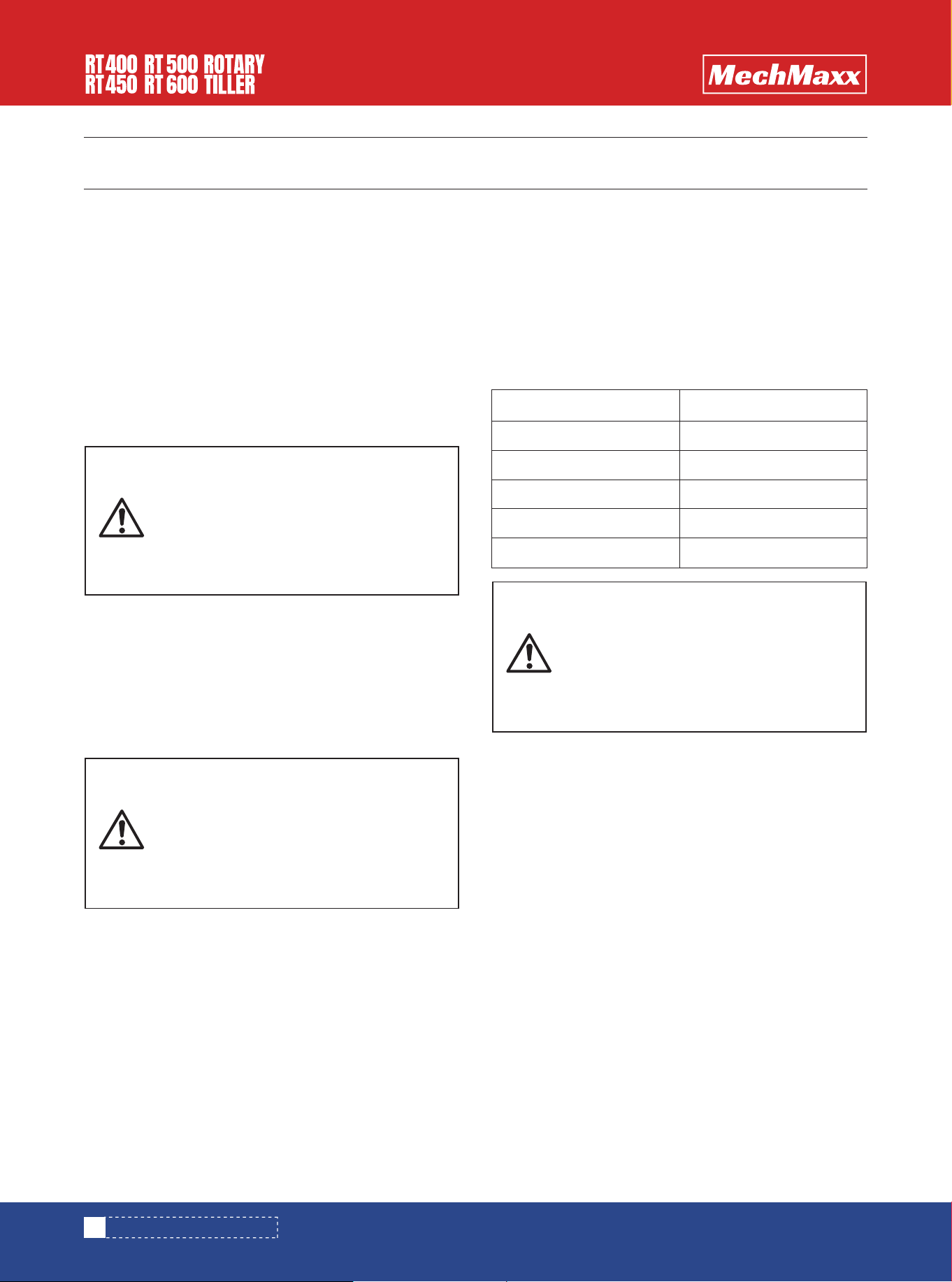
Lubrication Parts
Driveline U-Joint
Driveline Shaft
Gear Case
Bearing Of Rotor Shaft
Gearbox
Time
8 hours
8 hours
50 hours
20 hours
As Required
9
www. mechmaxx.com
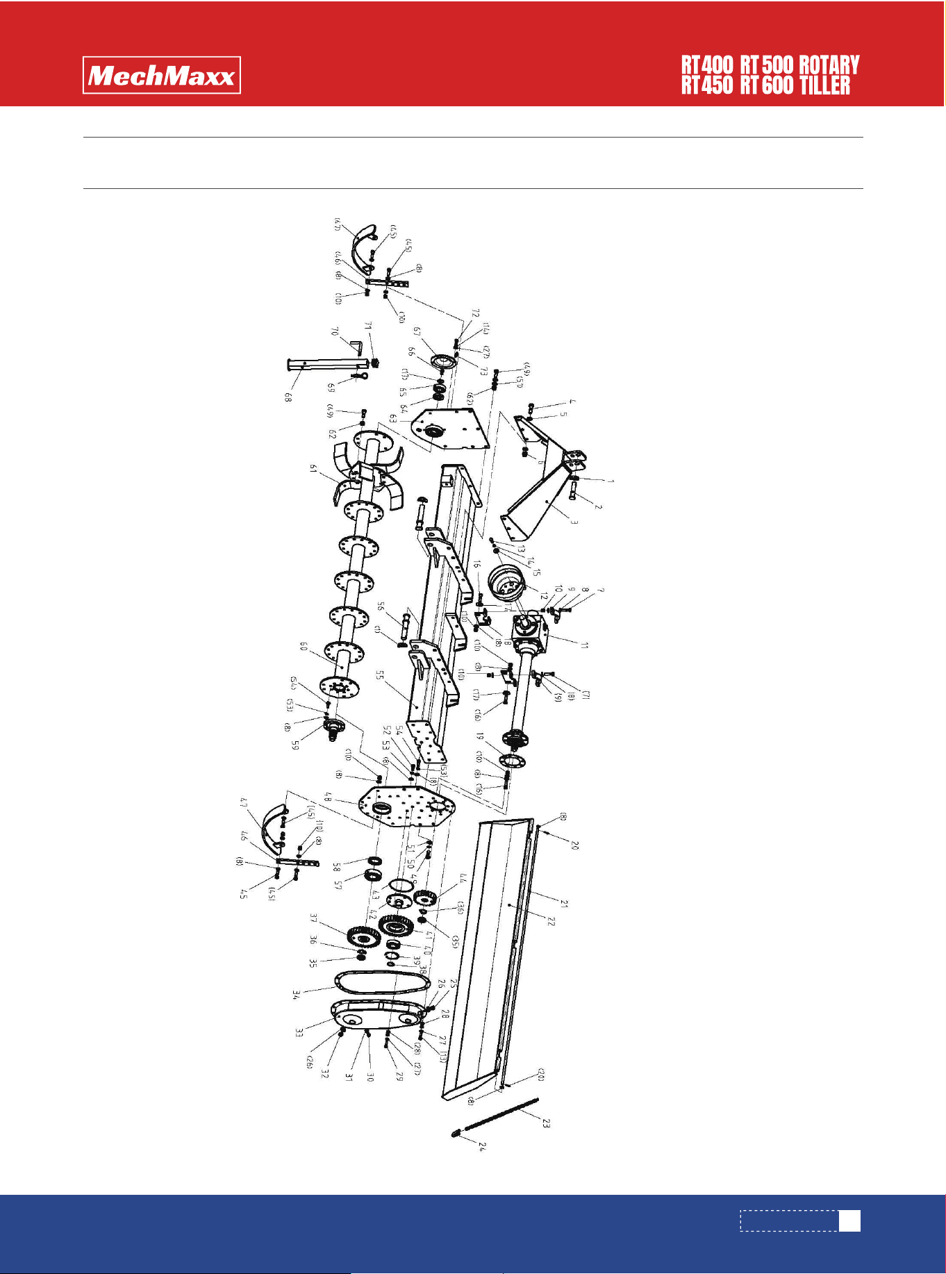
PARTS DIAGRAM
PARTS DIAGRAM

10
www. mechmaxx.com
PARTS LIST
PARTS LIST
REF DESCRIPTION QTY
1
2
3
4
5
6
7
8
9
10
11
12
13
14
15
16
17
18
19
20
21
22
23
24
25
26
27
28
29
Safty Pin 11
Upper Pin
Linkage
Bolt 16A50
PW16
Nylon Nut M16
Bolt M12*50
Plain Washer 12
Lock Plate
Nylon Nut M12
Hearbox Parts
PTO Cover
Bolt M10*35
Spring Washer 10
Big Plain Washer 10
Bolt M12*45
Big Plain Washer 12
Support Block
Splitter Pin
Gasket
Tailgate Weldment Axle
Tailgate Weldment
Chain 6
Shackle 6
Presure Relief Plug M16*1.5
Bonded Washer 16
Plain Washer 10
Nylon Nut M10
Bolt M10*40
3
1
1
6
12
6
4
55
2
22
1
1
18
6
2
12
5
2
1
2
1
1
2
2
1
2
44
20
4
REF DESCRIPTION QTY
30
31
32
33
34
35
36
37
38
39
40
41
42
43
44
45
46
47
49
50
51
52
53
54
55
56
57
58
59
1
1
1
1
1
2
2
1
1
1
1
1
1
1
6
2
2
1
10
4
16
2
13
11
1
2
1
1
1
Plug M10*1.25
Bonded Washer
Plug M16*1.4
Gear Cover
Gear Cover Gasket
Round Nut 30*1.5
Tap Washer For Round Nut 30
Bottom Gear
Circlip For Hole 80
Bearing 6307
Middle Gear
Middle Shaft
O Ring 140*4
Upper Gear
Bolt M12*40
Adjusting Plate
Skider
Left Plate
Bolt M14*40
Spring Washer
Plain Wahser 14
Bolt M12*25
Spring Washer 12
Bolt M12*30
Rotor Cover
Lower Pin
Bearing 6309
Oilseal 55*80*8
Rotor Shaft

11
www. mechmaxx.com
PARTS LIST
REF DESCRIPTION QTY
60
61
62
63
64
65
66
67
68
69
70
71
72
73
Rotor
C Blade
Nylon Nut M14
Right Plate
Oilseal 35*62*8
Bearing 6306
Bolt M12*20
Rotor Cap
Supportor
R Pin
L pin
Rubber Cap
Bolt M10*20
Grease Fitting M8*1
1
42
90
1
1
1
1
1
1
1
1
1
4
1
12
www. mechmaxx.com
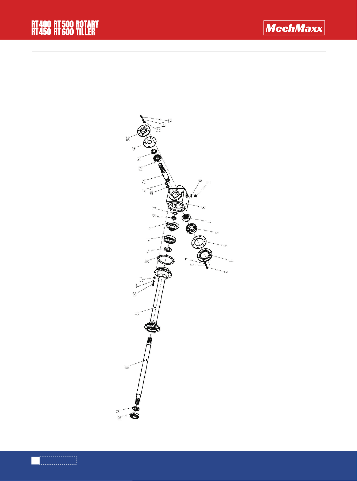
PARTS DIAGRAM
PARTS DIAGRAM

TABLE OF CONTENTS
13
www. mechmaxx.com
REF DESCRIPTION QTY
1
2
3
4
5
6
7
8
9
10
11
12
13
14
15
16
17
18
19
20
21
22
23
24
25
26
Rear End Cap
Bolt M10*25
Spring Washer 10
Plain Washer 10
Rear Gasket
Bearing 30310
Driving Gear
Gearbox
Presure Relief Plug
Bonded Washer
Tab Washer For Round Nut 30
Round Nut M30*1.5
Driven Gear
Bearing 30311
Oilseal 75*42*8
Shaft Cover Gasket
Shaft Cover
Shaft
Oilseal 70*40*8
Bearing 30308
Plug
Input Shaft
Bearing 30208
Oilseal 55*38*8
Front Gasket
Front End Cap
1
16
16
16
1
1
1
1
1
2
1
1
1
1
1
1
1
1
1
1
1
1
1
1
1
1
PARTS LIST