
Operator’s Manual
www.mechmaxx.com
3 POINT ROTARY TILLER
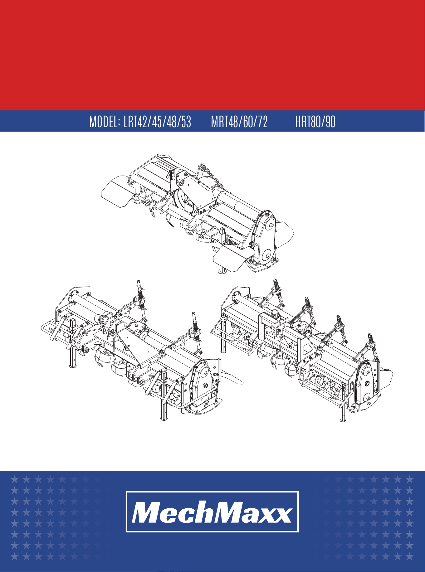
MODEL: LRT42/45/48/53
MRT48/60/72
HRT80/90


TABLE OF CONTENTS
TABLE OF CONTENTS
GENERAL INFORMATION
1
SAFETY SIGNS 3
3
ASSEMBLY AND ADJUSTMENT
7
PTO SHAFT CONNECTION
7
PERSONAL PROTECTIVE EQUIPMENT
8
SAFE OPERATING AREA
8
BEFORE LEAVING THE TRACTOR
8
OPERATING RESTRICTIONS
8
DUST AND RESPIRATORY PROTECTION
8
TRACTOR HANDLING AND STABILITY
8
FASTENER INSPECTION
8
MACHINES SUPPLIED PARTLY DISASSEMBLED
8
BEFORE USE
8
ROTOR
9
ROUTINE MAINTENANCE
9
SAFETY NOTICE
9
GREASING AND LUBRICATION
9
UNLOADING AND POSITIONING
TRACTOR CAPACITY AND STABILITY
5
6
6
6
ABOUT THIS MANUAL
3
MACHINE IDENTIFICATION
3
INTENDED USE
3
SAFETY NOTICE – REAR ACCESS DOOR
3
OPERATOR RESPONSIBILITY
3
WORK AREA AND OPERATING LIMITS
3
NOISE LEVEL
4
STORAGE AND DISPOSAL
4
MACHINE COMPONENTS
4
IMPORTANT SAFETY INFORMATION
4
BEFORE OPERATION:
5
DURING OPERATION:
5
MAINTENANCE AND ADJUSTMENTS:
5
SAFETY INFORMATION
TRANSPORT AND INSTALLATION
7
CONNECTING THE ROTARY TILLER TO THE TRACTOR
8
USE OF THE MACHINE
9
MAINTENANCE
12
LRT42/45/48/53 PARTS DIAGRAM
12
LRT42/45/48/53 PARTS LIST
24
MRT48/60/72 PARTS DIAGRAM
24
MRT48/60/72 PARTS LIST
37
HRT80/90 PARTS DIAGRAM
37
HRT80/90 PARTS LIST
1
www.mechmaxx.com
TABLE OF CONTENTS

2
www.mechmaxx.com
We want to thank you for having chosen one of our products.
Technological evolution and the new demands of the agricultural industry have pushed our firm toward continuous
improvement, focusing on the product itself, the quality of materials, and the quality of workmanship.
This manual contains a description of the machine and the necessary instructions for correct use, along with instructions
for ordinary and periodic maintenance of the rotary tiller. The manual is subdivided into easily recognizable chapters for
practical reference.
The information in this manual is intended for professional users who must have specific knowledge of the operating
characteristics of the tractor to which the machine is connected. The user must be authorized, instructed, and appropri-
ately trained.
We recommend that you use only original spare parts and accessories.
The use of non-original parts could be dangerous, reducing the service life and performance of the machine, as well as
voiding the warranty.
The manufacturer shall not be held liable for damage, injury, or loss resulting from misuse, improper installation, unautho-
rized modification, or operation outside the intended use of this machine.
In case of doubt regarding the interpretation of the subjects illustrated in this handbook, we suggest that you contact
your dealer, who will be ready to assist you whenever needed.
3
www.mechmaxx.com
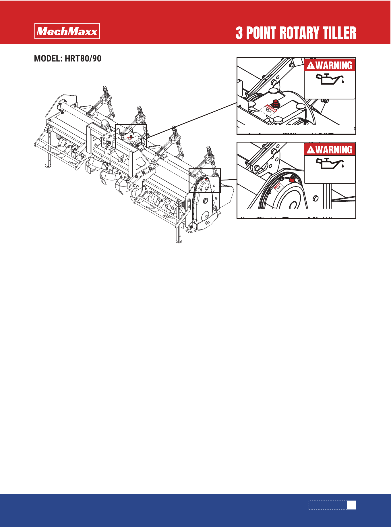
0.5L (0.53 quarts) is required.Gearoil type: 80W-90
MUST ADD GEARBOX OIL
BEFORE FIRST USE
1L (1.057 quarts) is required.Gearoil type: 80W-90
MUST ADD GEARBOX OIL
BEFORE FIRST USE
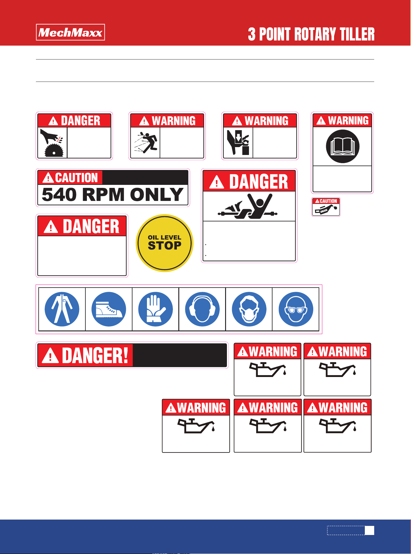
SAFETY SIGNS
SAFETY SIGNS
The rating plate on your machine may show symbols. These represent important information about the product or instruc-
tions on its use.
ROTATING
BLADES
KEEP HANDS
AWAY
KEEP BYSTANDERS AWAY.
DO NOT OPERATE NEAR PEOPLE.
FLYING
OBJECTS
HAZARD
KEEP CLEAR.
To avoid Injury or Machine Damage:
Operate only with 540 rpm PTO
PINCH POINT
HAZARD
KEEP CLEAR
Read and under-
stand operator's
manual before using
this machine.
All driveline guards, tractor, and equipment
shields in place.
ROTATING DRIVELINE CONTACT CAN
CAUSE DEATH KEEP AWAY!
DO NOT OPERATE WITHOUT :
Drivelines securely attached at both ends.
GUARD MISSING
WHEN THIS IS VISIBLE
DO NOT OPERATE
ENTANGLEMENT
HAZARD
C
H
E
C
K
G
E
A
R
B
O
X
B
E
F
O
R
E
S
T
A
R
T
U
P
!
!
2L (2.11 quarts) is required.Gearoil type: 80W-90
MUST ADD GEARBOX OIL
BEFORE FIRST USE
1.5L (1.59 quarts) is required.Gearoil type: 80W-90
MUST ADD GEARBOX OIL
BEFORE FIRST USE
2.5L (2.64 quarts) is required.Gearoil type: 80W-90
MUST ADD GEARBOX OIL
BEFORE FIRST USE

4
www.mechmaxx.com
ABOUT THIS MANUAL
WORK AREA AND OPERATING LIMITS
NOISE LEVEL
MACHINE COMPONENTS
IMPORTANT SAFETY INFORMATION
MACHINE IDENTIFICATION
INTENDED USE
SAFETY NOTICE – REAR ACCESS DOOR
OPERATOR RESPONSIBILITY
GENERAL INFORMATION
GENERAL INFORMATION
This operator’s manual provides essential safety, opera-
tion, and maintenance information for this rotary tiller.
Reading and following all instructions will help ensure
safe operation, reliable performance, and long service life.
This manual is considered a permanent part of the
machine and must remain with the unit if sold, trans-
ferred, or stored.
Illustrations shown may differ slightly from the actual
machine and are intended for reference only.
Safety decals and pictograms installed on the machine
must be kept clean, legible, and replaced if damaged.
Each machine is equipped with an identification plate
mounted on the frame. This plate includes the model
number, serial number, year of manufacture, and machine
weight.
This rotary tiller is designed exclusively for agricultural
soil cultivation.
Use for any purpose outside of agriculture is prohibited.
Rotary tillers equipped with a rear access door must be
operated with the door fully closed at all times.
The rear door may only be opened when the machine is
shut down for inspection, cleaning, or maintenance.
Operating the machine with the rear door open is consid-
ered unsafe and improper use.
Only one trained operator may operate the machine at a
time.
Operators must be properly trained, authorized, and famil-
iar with tractor-mounted implements.
Adequate tractor lighting must be used when operating in
low-light conditions.
Unauthorized modifications void manufacturer responsi-
bility.
Proper operation and compliance with safety instructions
reduce the risk of injury and extend equipment life.
Remove large stones, debris, and foreign objects before
operation.
Do not operate near buried obstacles, tree stumps, or
metal objects.
Keep all bystanders at a safe distance during operation.
Avoid operating at very low working depth on wet soil.
Excessively shallow operation over long periods may
compact soil and reduce future cultivation effectiveness.
Sound pressure levels may exceed 84 dB(A) depending on
operating conditions. Hearing protection is recommended.
STORAGE AND DISPOSAL
Store the machine in a dry, sheltered area when not in
use.
Clean, lubricate, and protect all mechanical components
before long-term storage.
Dispose of oils, lubricants, and machine components in
accordance with local environmental regulations.
This rotary tiller connects to the tractor via a three-point
hitch and is powered by the PTO.
Main components include:
• Top link connection
• Lower hitch arms
• PTO support
• Depth control skids
• Gearbox
• Rotor with cutting blades
The following safety instructions are provided to help
prevent personal injury and equipment damage.
Read, understand, and follow all safety instructions
before operating or servicing this machine. Failure to
follow these instructions may result in serious injury or
death.

5
www.mechmaxx.com
This rotary tiller is designed for agricultural use only and
must be operated in accordance with all safety instruc-
tions provided in this manual.
Only one trained and authorized operator may operate the
machine at any time. Operators must be familiar with
tractor-mounted implements and associated hazards.
• Ensure all guards, shields, and safety devices are
properly installed and in good condition.
• Verify the PTO shaft and protective covers are intact.
• Remove stones, debris, and foreign objects from the
work area.
• Keep all bystanders and animals at a safe distance.
• Do not operate near buried obstacles, tree stumps, or
metal objects.
• Never approach moving parts or the PTO shaft while the
machine is running.
• Do not ride on the machine at any time.
• Shut off the tractor engine, engage the parking brake,
and remove the ignition key before servicing.
• Allow all rotating components to come to a complete
stop.
• Use only manufacturer-approved replacement parts.
Failure to follow these instructions may result in serious
injury or equipment damage.
BEFORE OPERATION:
DURING OPERATION:
MAINTENANCE AND ADJUSTMENTS:
SAFETY INFORMATION
SAFETY INFORMATION
6
www.mechmaxx.com
Use extreme caution during loading and unloading operations. These tasks must be performed by trained and qualified
personnel using appropriate lifting equipment.
For transport, place the machine securely on pallets and fasten it with suitable restraints. Always use lifting equipment
with sufficient rated capacity.
Do not lift the machine using straps alone. Use only the designated lifting points and approved lifting hooks or cables as
indicated on the machine.
Before attaching the rotary tiller, ensure that the tractor has adequate lifting capacity and stability for the installed
equipment.
Front ballast may be required to maintain proper weight distribution and steering control.
Failure to verify tractor capacity and stability may result in loss of control, tipping, or serious injury.
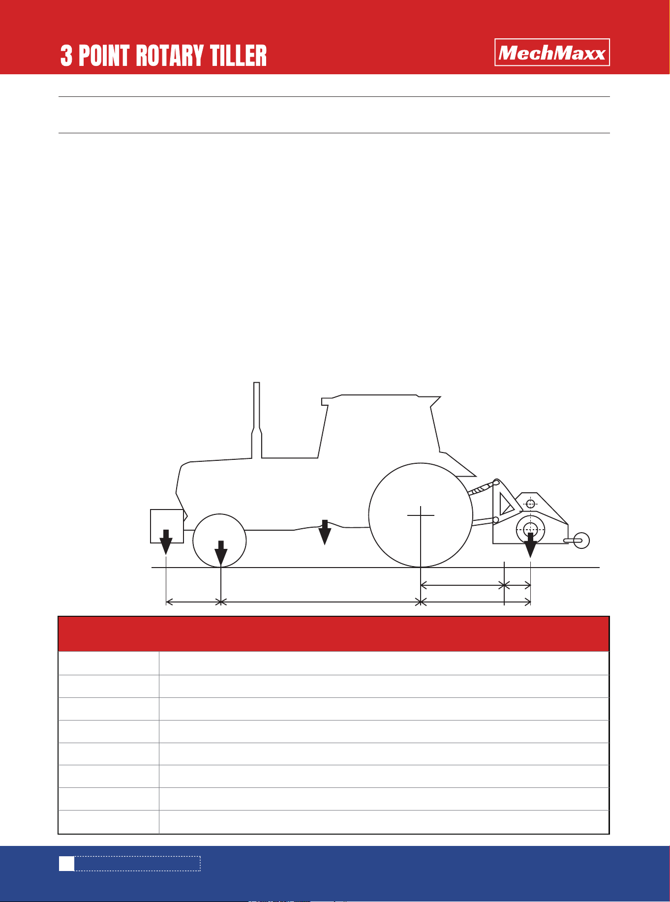
Verify the lifting capability and the stability of the tractor through the following formula and if necessary apply frontally
the ballasts.
UNLOADING AND POSITIONING
TRACTOR CAPACITY AND STABILITY
M X s ≤ 0,2 T X i + Z (d+i)
M ≤ 0,3 T
TRANSPORT AND INSTALLATION
TRANSPORT AND INSTALLATION
i
d
s
s1
s2
T
Z
M
Axle base wheels tractor
Distance of the front axle from the ballasts
Overhang of the rear axle of the operator machine S=S1 + S2
Distance of the tractor front axle to the end lifting arms
Distance of the shredder barycentre to the centre holes lifting pins
Mass of the tractor +75 kg (165 lbs) (operator)
Mass of the ballasts
Mass of the whole loaded machine
Z
d i s
s1 s2
0.2 T
T
M

7
www.mechmaxx.com
CONNECTING THE ROTARY TILLER TO THE TRACTOR
CONNECTING THE ROTARY TILLER TO THE TRACTOR
Attaching implements affects tractor handling, steering, and braking performance.
Ensure adequate front axle load after installation. The front axle must support at least 20% of the tractor’s unloaded
weight.
Before installation, secure the tractor’s hydraulic controls to prevent unintended movement.
The rotary tiller must be compatible with a standard three-point hitch system.
Keep hands and body clear of lift arms and linkage areas during installation.
Do not use external hydraulic controls while attaching the machine.
Lock all stabilizers and lift controls before transport.
Park the tractor on level ground, shut off the engine, and engage the parking brake.
Align the lower lift arms with the hitch points and secure them using approved hitch pins and safety clips.
Attach and adjust the top link so the rotary tiller remains level during operation.
Ensure rotor blades do not contact the ground while rotating. If equipped with depth skids, verify full ground contact.
ASSEMBLY AND ADJUSTMENT
Connect the PTO shaft to the gearbox and tractor PTO output. Ensure the safety lock is engaged and the anti-rotation
chain is secured.
Operate only at 540 RPM PTO speed. Always connect the PTO shaft last and disconnect it first.
PTO SHAFT CONNECTION

8
www.mechmaxx.com
USE OF THE MACHINE
USE OF THE MACHINE
During operation, the operator must wear suitable person-
al protective equipment, including protective footwear,
work gloves, protective clothing, eye protection, and
hearing protection. Proper PPE helps reduce the risk of
injury caused by debris, noise, or contact with moving
parts.
Ensure that all bystanders remain at a safe distance. A
minimum distance of 165 feet (50 m) is recommended
depending on operating conditions.
PERSONAL PROTECTIVE EQUIPMENT
SAFE OPERATING AREA
Before dismounting from the tractor or carrying out any
maintenance, adjustment, or inspection, engage the
parking brake, disengage the PTO, shut off the engine,
remove the ignition key, and wait until all rotating and
moving components have completely stopped.
BEFORE LEAVING THE TRACTOR
Do not operate the rotary tiller in reverse. When changing
direction or turning, always raise the implement
completely out of the soil. Turning with the tiller engaged
in the ground may result in equipment damage or loss of
control.
OPERATING RESTRICTIONS
Operation in dry soil conditions may generate dust. It is
recommended to use a tractor equipped with an enclosed
cab and air filtration system or to wear appropriate respi-
ratory protection such as a dust mask or filtered respira-
tor.
DUST AND RESPIRATORY PROTECTION
The use of mounted or towed implements can significant-
ly affect tractor handling, steering response, and braking
performance. Extra caution must be taken when turning,
as the altered center of gravity may increase centrifugal
forces.
TRACTOR HANDLING AND STABILITY
All nuts, bolts, and fasteners must be inspected periodi-
cally. Retighten any loose components to ensure safe and
reliable operation.
FASTENER INSPECTION
For transportation and packaging efficiency, the rotary
tiller may be supplied partially disassembled. Detached
components are packed together with the main unit. In
most cases, the three-point hitch frame is shipped sepa-
rately and must be assembled at the customer’s location
before operation.
•Before starting the machine, verify that the rotary tiller
is in proper working condition, that all lubrication points
are correctly serviced, and that no components show
excessive wear or damage.
•Ensure the tiller is correctly positioned to achieve the
desired working depth.
•All safety guards and protective devices, which may
have been removed for shipping, must be properly
installed and secured before commissioning the
machine.
MACHINES SUPPLIED PARTLY
DISASSEMBLED
BEFORE USE

9
www.mechmaxx.com
MAINTENANCE
MAINTENANCE
M8×1
M10×1.25
M12×1.25
M14×1.5
M16×1.5
M18×1.5
M20×1.5
M22×1.5
M24×2
M27×2
M30×2
11
22
38
60
88
128
178
237
303
443
614
19
38
67
107
158
227
318
421
539
789
1091
27
55
94
148
222
319
447
592
758
1109
1535
32
65
113
178
266
384
536
711
910
1332
1842
Metric Bolt Tightening Torques (ft-lb)
6.8
Bolt Grade
Fine Thread
Bolts
8.8 10.9 12.9
General Maintenance Requirements
All maintenance and service operations must be carried
out only by trained and competent personnel. Before
performing any maintenance, the rotary tiller must be
completely stopped and disconnected from the tractor.
The condition of the tiller blades must be inspected daily.
Worn, cracked, or damaged blades must be replaced
immediately, as blade failure may result in hazardous
ejection of parts during operation.
Every 4 Operating Hours
Check the tightness of all fastening nuts.
After 50 Operating Hours
Check the oil level in the transmission unit and restore it
to the correct level as required.
Every 100 Operating Hours
Recheck the transmission oil level and top up if neces-
sary.
Note: Torque values are approximate and provided for
reference only. Always follow fastener manufacturer
specifications.
The rotor shaft is factory balanced. When replacing blades
or tools, it is strongly recommended to replace the entire
set to maintain proper balance.
Installing non-original or mismatched components may
cause excessive vibration and can lead to premature
bearing failure.
Replacement of damaged rotor components must be
performed by qualified service personnel.
ROTOR
Routine maintenance must be performed with the rotary
tiller disconnected from the tractor and positioned
securely on level ground.
All inspection, adjustment, and cleaning work must be
carried out only when:
The implement is resting on the ground
The tractor engine is shut off
The PTO driveline is disengaged
The parking brake is applied
The ignition key has been removed
Adjustments must only be made with the engine shut off,
PTO disengaged, ignition key removed, and all mechanical
components completely stopped.
In the event of a malfunction, the operator must immedi-
ately disengage the PTO, turn off the engine, remove the
ignition key, exit the tractor, and identify the cause before
attempting any corrective action.
ROUTINE MAINTENANCE
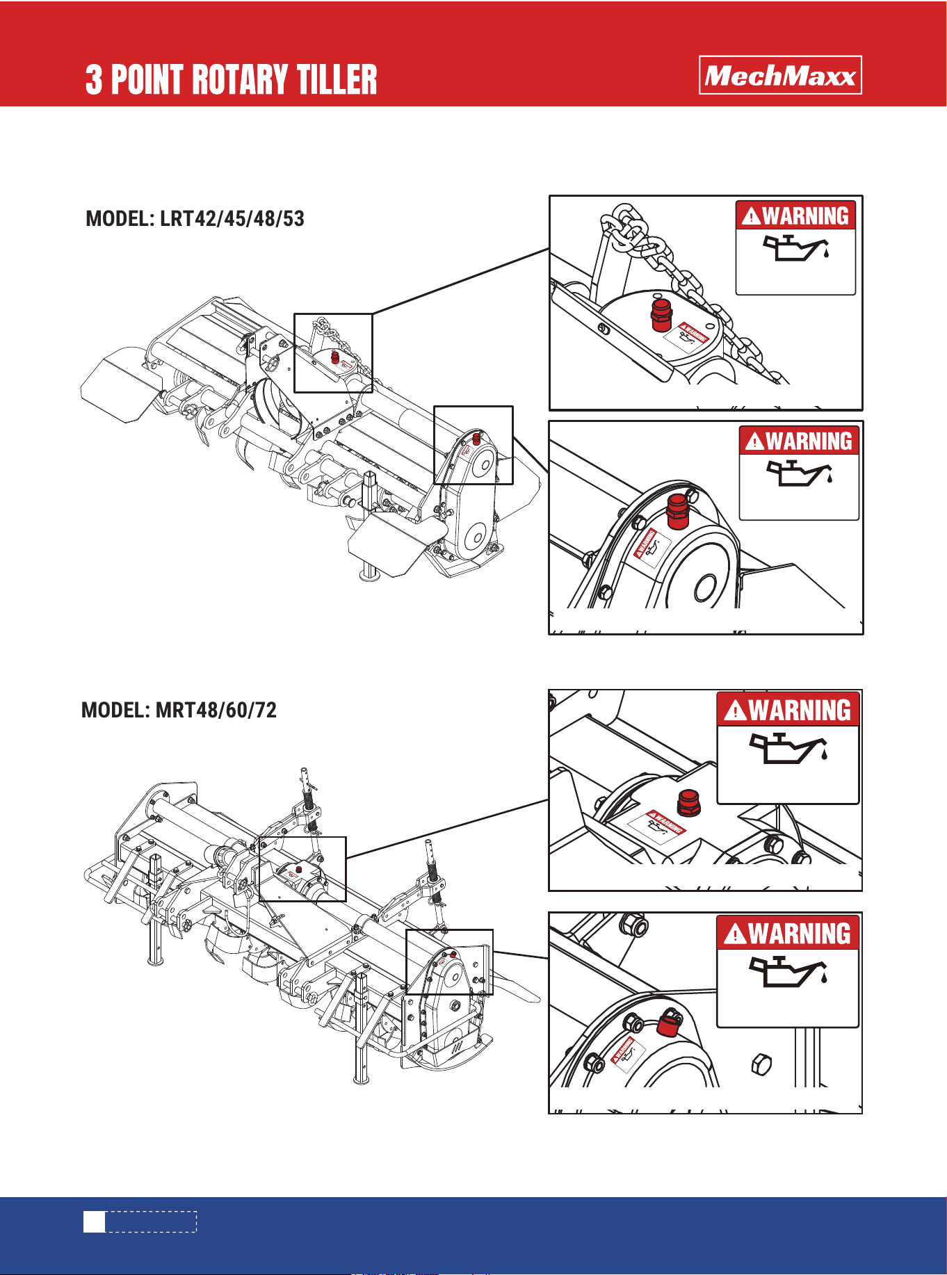
GREASING AND LUBRICATION
SAFETY NOTICE
Torque values shown are metric fasteners converted to
ft-lb for reference.
10
www.mechmaxx.com
0.5L (0.53 quarts) is required.Gearoil type: 80W-90
MUST ADD GEARBOX OIL
BEFORE FIRST USE
0.5L (0.53 quarts) is required.Gearoil type: 80W-90
MUST ADD GEARBOX OIL
BEFORE FIRST USE
UNIT IS SHIPPED WITHOUT OIL IN THE GEARBOX AND WITHOUT GREASE IN THE GREASE FITTINGS.
ADD OIL AND GREASE BEFORE OPERATION.
0.5L (0.53 quarts) is required.Gearoil type: 80W-90
MUST ADD GEARBOX OIL
BEFORE FIRST USE
0.5L (0.53 quarts) is required.Gearoil type: 80W-90
MUST ADD GEARBOX OIL
BEFORE FIRST USE
0.5L (0.53 quarts) is required.Gearoil type: 80W-90
MUST ADD GEARBOX OIL
BEFORE FIRST USE
0.5L (0.53 quarts) is required.Gearoil type: 80W-90
MUST ADD GEARBOX OIL
BEFORE FIRST USE
1L (1.057 quarts) is required.Gearoil type: 80W-90
MUST ADD GEARBOX OIL
BEFORE FIRST USE
0.5L (0.53 quarts) is required.Gearoil type: 80W-90
1L (1.057 quarts) is required.Gearoil type: 80W-90
1L (1.057 quarts) is required.Gearoil type: 80W-90
MUST ADD GEARBOX OIL
BEFORE FIRST USE
2L (2.11 quarts) is required.Gearoil type: 80W-90
MUST ADD GEARBOX OIL
BEFORE FIRST USE
1L (1.057 quarts) is required.Gearoil type: 80W-90
MUST ADD GEARBOX OIL
BEFORE FIRST USE
1L (1.057 quarts) is required.Gearoil type: 80W-90
MUST ADD GEARBOX OIL
BEFORE FIRST USE
1L (1.057 quarts) is required.Gearoil type: 80W-90
1L (1.057 quarts) is required.Gearoil type: 80W-90
MUST ADD GEARBOX OIL
BEFORE FIRST USE
2L (2.11 quarts) is required.Gearoil type: 80W-90
MUST ADD GEARBOX OIL
BEFORE FIRST USE
2L (2.11 quarts) is required.Gearoil type: 80W-90
2L (2.11 quarts) is required.Gearoil type: 80W-90
MUST ADD GEARBOX OIL
BEFORE FIRST USE
MAINTENANCE
MODEL: LRT42/45/48/53
MODEL: MRT48/60/72
11
www.mechmaxx.com
MAINTENANCE
0.5L (0.53 quarts) is required.Gearoil type: 80W-90
MUST ADD GEARBOX OIL
BEFORE FIRST USE
2L (2.11 quarts) is required.Gearoil type: 80W-90
MUST ADD GEARBOX OIL
BEFORE FIRST USE
1.5L (1.59 quarts) is required.Gearoil type: 80W-90
MUST ADD GEARBOX OIL
BEFORE FIRST USE
2.5L (2.64 quarts) is required.Gearoil type: 80W-90
MUST ADD GEARBOX OIL
BEFORE FIRST USE
1.5L (1.59 quarts) is required.Gearoil type: 80W-90
MUST ADD GEARBOX OIL
BEFORE FIRST USE
1.5L (1.59 quarts) is required.Gearoil type: 80W-90
MUST ADD GEARBOX OIL
BEFORE FIRST USE
1.5L (1.59 quarts) is required.Gearoil type: 80W-90
MUST ADD GEARBOX OIL
BEFORE FIRST USE
2.5L (2.64 quarts) is required.Gearoil type: 80W-90
MUST ADD GEARBOX OIL
BEFORE FIRST USE
2.5L (2.64 quarts) is required.Gearoil type: 80W-90
MUST ADD GEARBOX OIL
BEFORE FIRST USE
1.5L (1.59 quarts) is required.Gearoil type: 80W-90
2.5L (2.64 quarts) is required.Gearoil type: 80W-90
MODEL: HRT80/90
12
www.mechmaxx.com
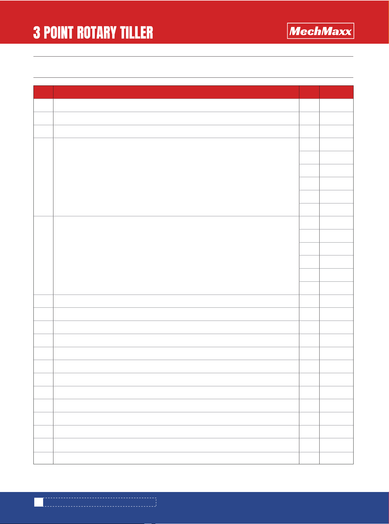
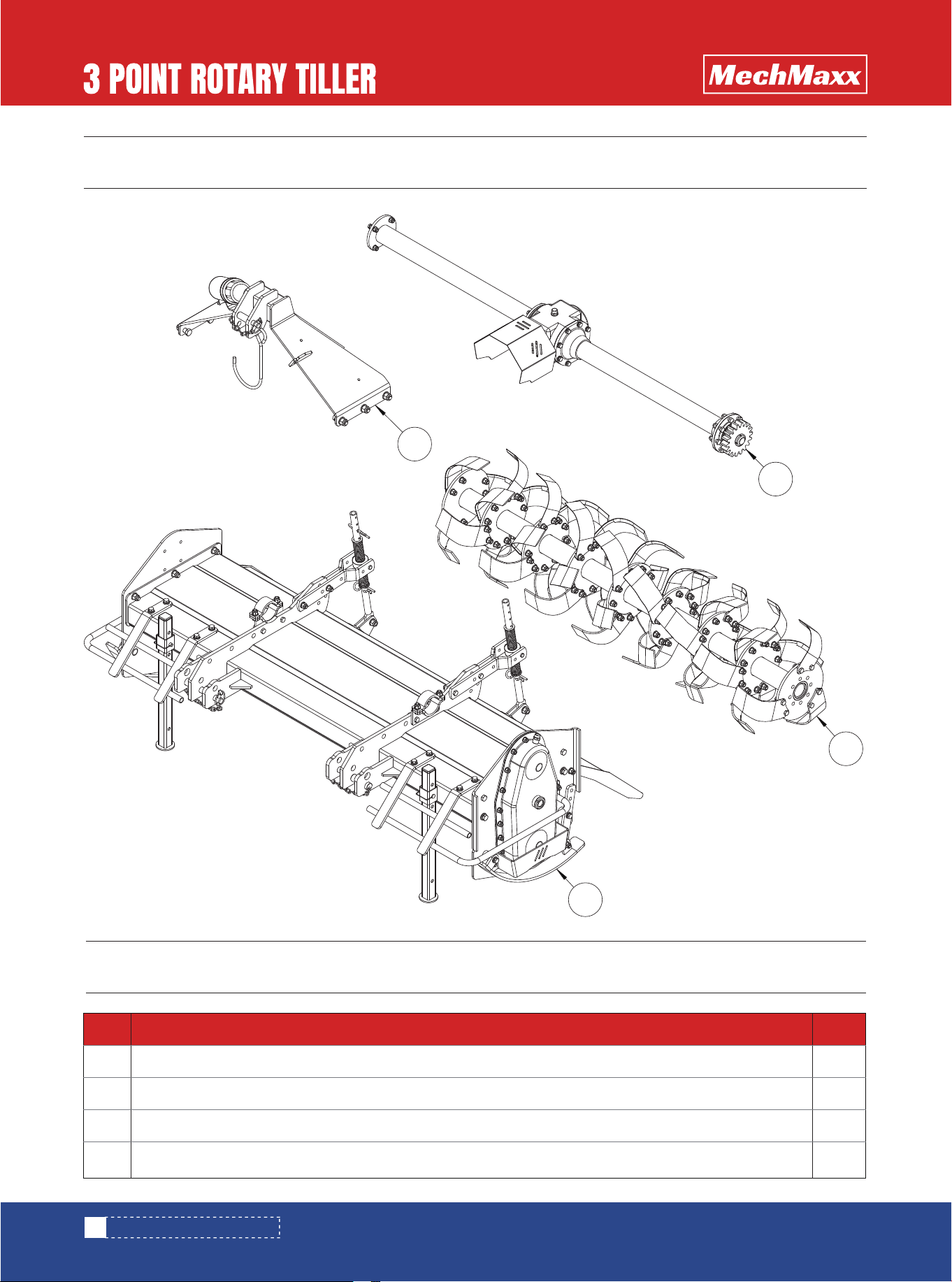
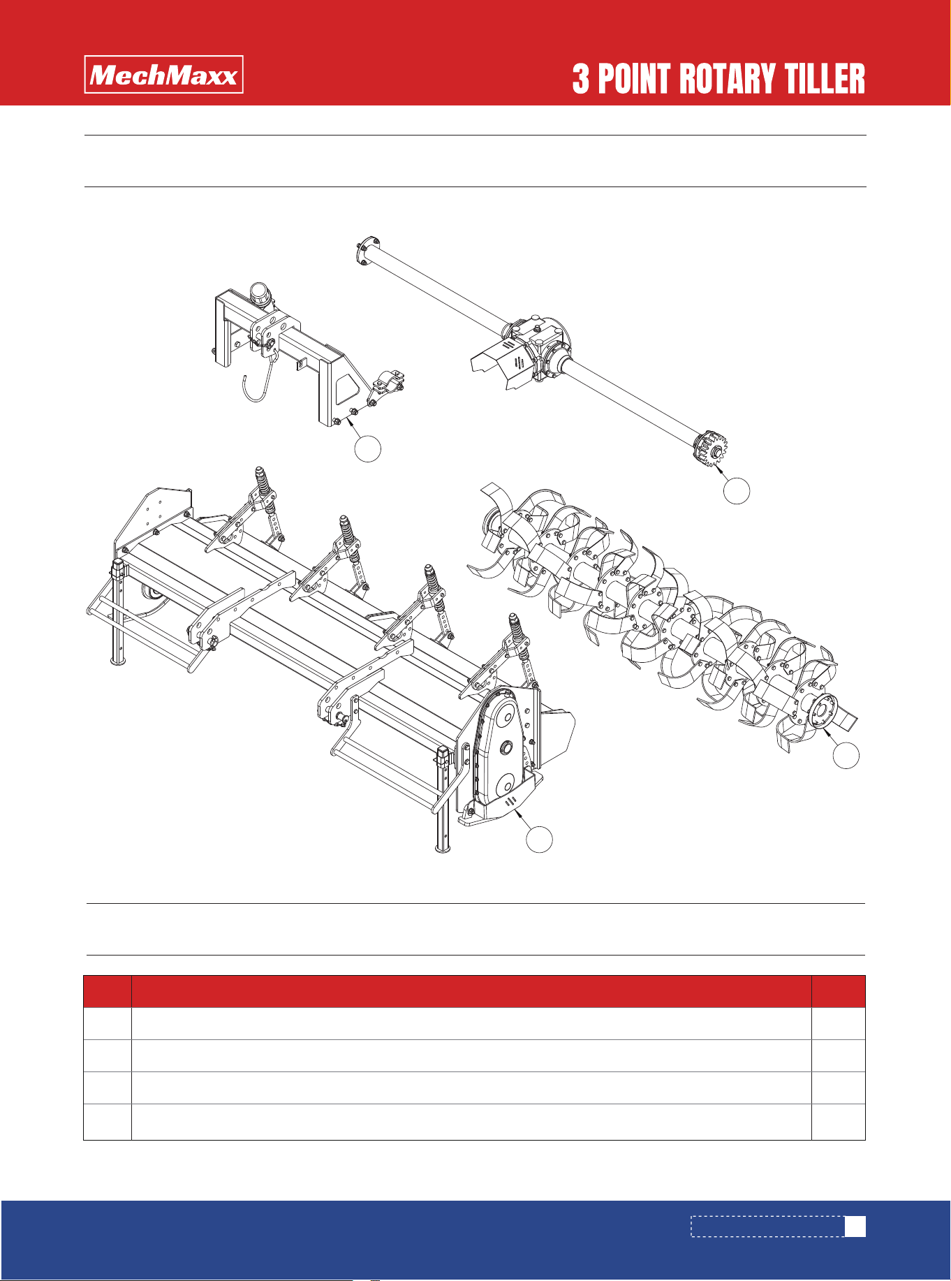
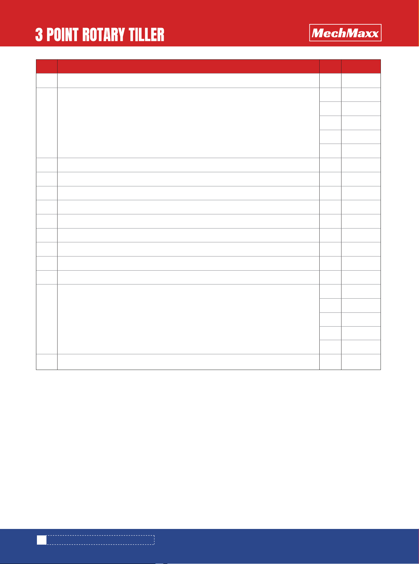
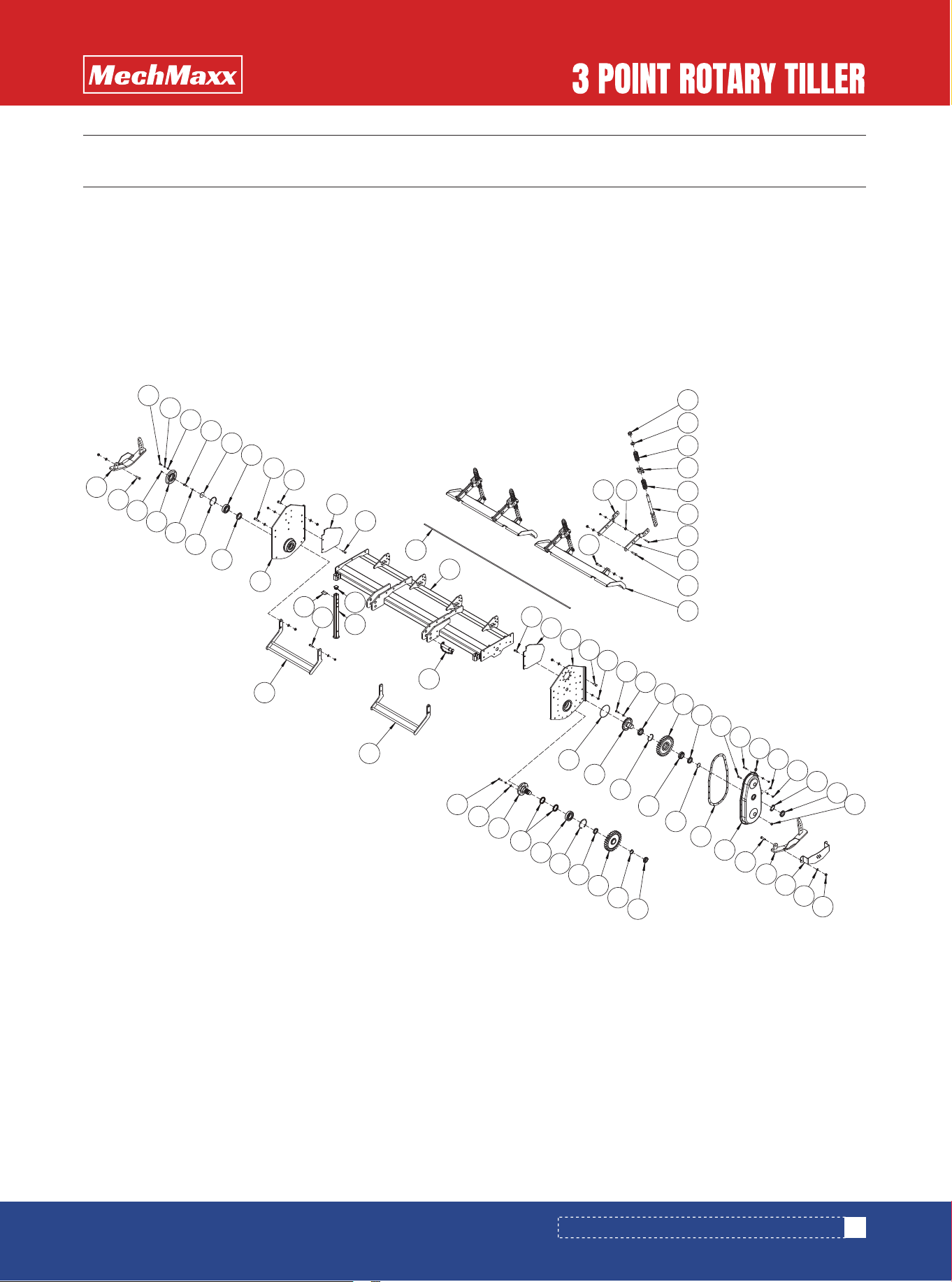
LRT42/45/48/53 PARTS DIAGRAM
LRT42/45/48/53 PARTS DIAGRAM
LRT42/45/48/53 PARTS LIST
1
1
1
1
No. DESCRIPTION Qty
1
2
3
4
3-Point Hitch Assembly
Gearbox Assembly
Tiller Hood Assembly
Rotor Shaft Assembly
1
2
3
4
13
www.mechmaxx.com
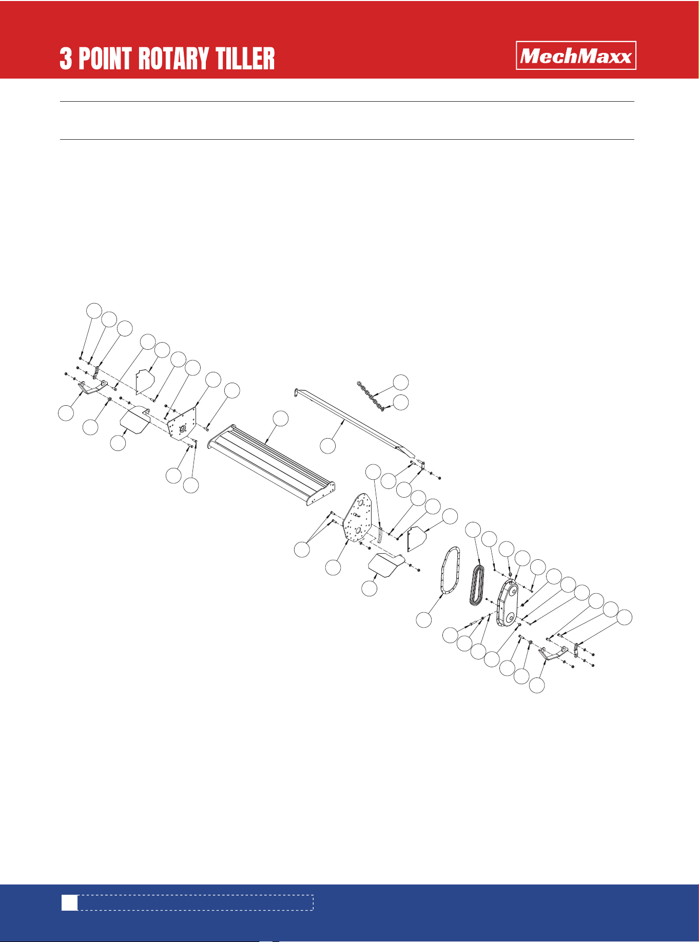
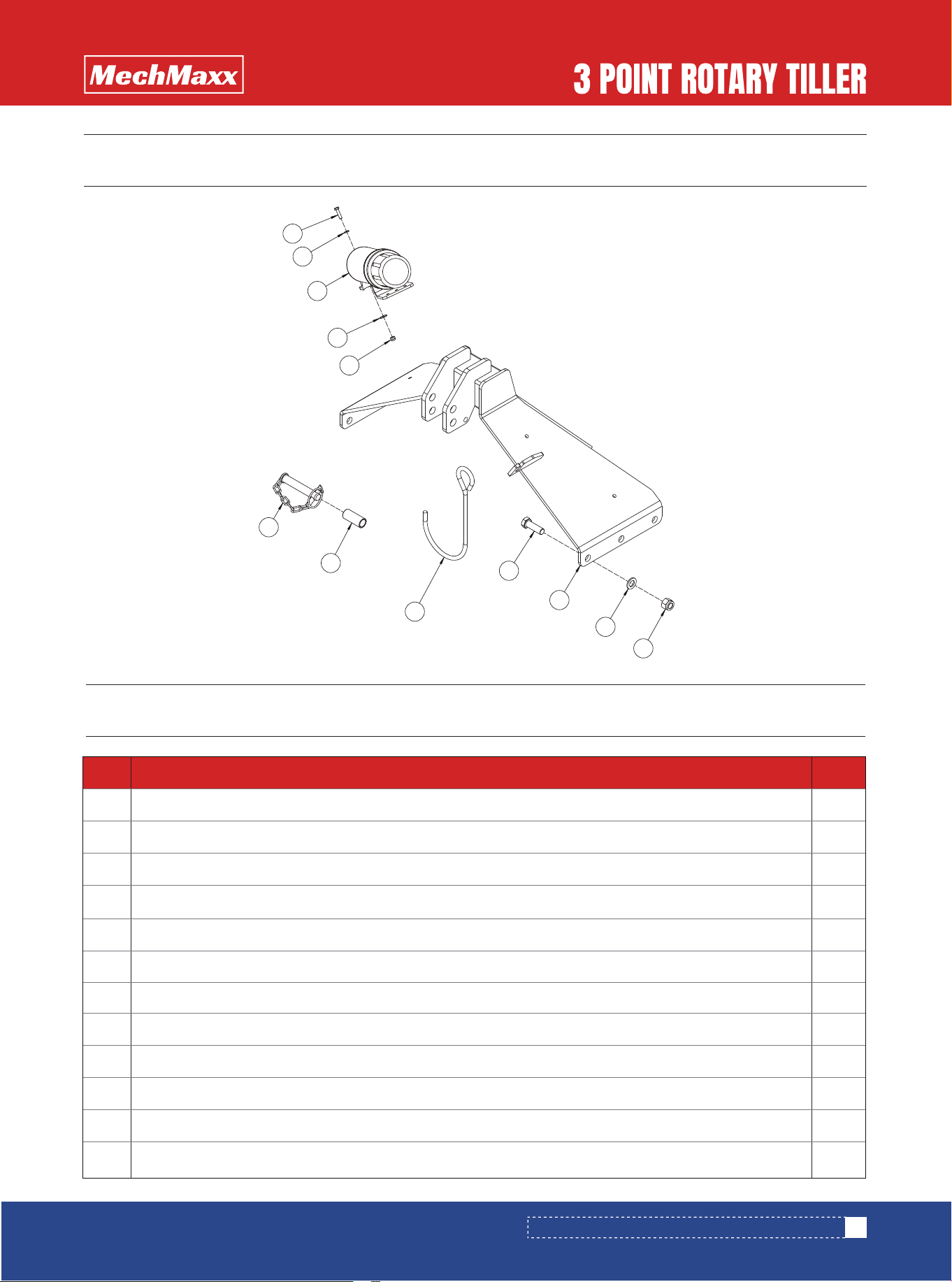
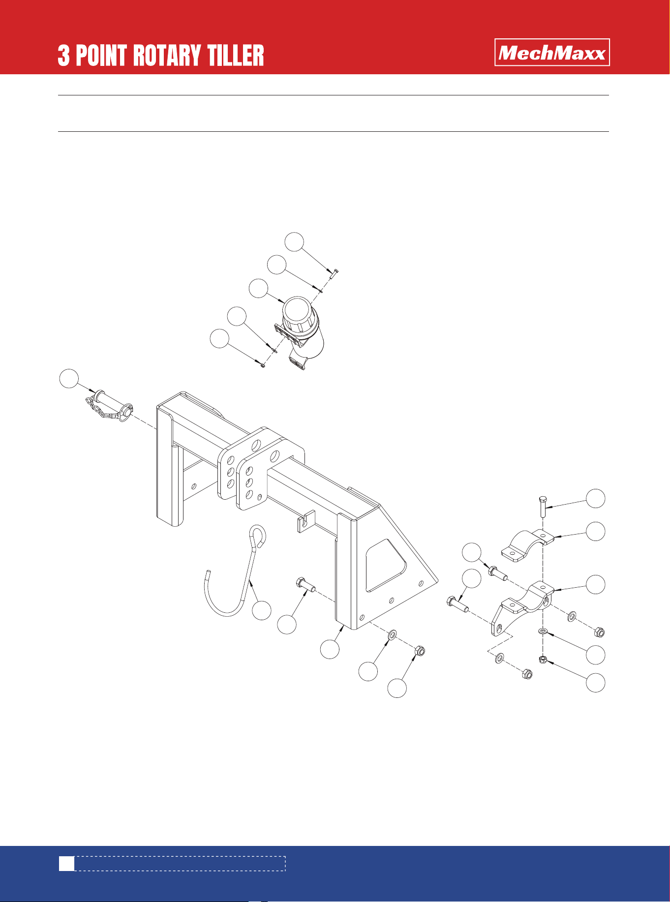
LRT42/45/48/53 PARTS DIAGRAM (3-POINT HITCH ASSEMBLY)
LRT42/45/48/53 PARTS DIAGRAM (3-POINT HITCH ASSEMBLY)
1
13
9
2
12
5
11
3
14
6
7
10
8
19
15
4
18
16
17
4

14
www.mechmaxx.com
LRT42/45/48/53 PARTS LIST (3-POINT HITCH ASSEMBLY)
LRT42/45/48/53 PARTS LIST (3-POINT HITCH ASSEMBLY)
4
8
1
4
2
4
1
2
1
8
1
16
8
1
1
1
1
1
1
No. DESCRIPTION Qty
1
2
3
4
5
6
7
8
9
10
11
12
13
14
15
16
17
18
19
Lock Nut M8
Flat Washer M8
Operator’s Manual Tube (Small)
Hex Bolt M8 × 20
Lock Nut M6
Flat Washer M6
Hitch Hook
Hex Bolt M6 × 20
Upper Hitch Pin
Hex Bolt M10 × 30
Right Upper Hitch Weldment
Flat Washer M10
Lock Nut M10
Upper Hitch Connecting Plate
Lock Nut M12
Flat Washer M12
Upper Hitch Spacer Sleeve
Left Upper Hitch Weldment
Hex Bolt M12 × 90
15
www.mechmaxx.com
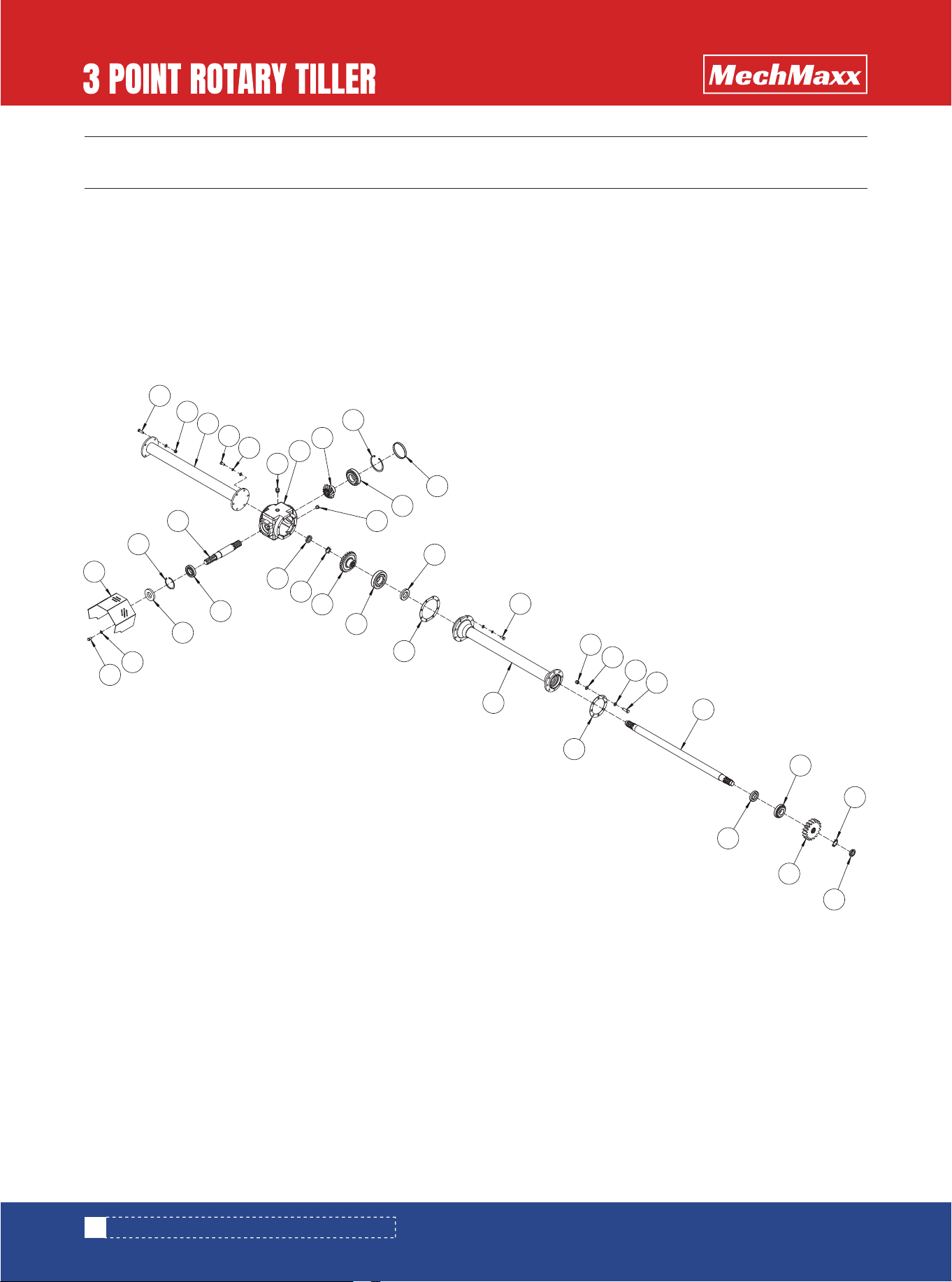
LRT42/45/48/53 PARTS DIAGRAM (GEARBOX ASSEMBLY)
LRT42/45/48/53 PARTS DIAGRAM (GEARBOX ASSEMBLY)
14
27
1
13
2
15
24
32
28
12
3
23
10
16
22
11
4
17
31
26
25
29
18
9
30
7
19
5
6
10
21
20
10
10
8
16
www.mechmaxx.com
LRT42/45/48/53 PARTS LIST (GEARBOX ASSEMBLY)
LRT42/45/48/53 PARTS LIST (GEARBOX ASSEMBLY)
1
1
1
1
1
1
1
1
1
1
1
1
1
1
1
2
1
4
10
12
1
1
1
1
1
1
1
1
No. DESCRIPTION Qty
1
2
3
4
5
6
7
8
9
10
11
12
13
14
15
16
17
18
End Cap Ø55 × 10
Right Side Guard Weldment
Gearbox Assembly
Side Drive Shaft
Left Side Guard Weldment
Hex Bolt M10 × 20
Upper Bearing Housing
Copper Washer Ø10
Spring Washer M10
Hex Bolt M10 × 30
Drive Shaft Spacer Sleeve
Deep Groove Ball Bearing 6306
Drive Sprocket
External Retaining Ring Ø30
Shim (1 mm)
Oil Seal 40 × 62 × 8
O-Ring 30 × 2.65
Paper Gasket
Remarks
85
95
105
115
125
135
85
95
105
115
125
135

17
www.mechmaxx.com
LRT42/45/48/53 PARTS LIST (GEARBOX ASSEMBLY)
1
1
1
1
1
1
4
14
1
2
2
4
4
2
1
2
1
1
1
No. DESCRIPTION Qty
19
20
21
22
23
24
25
26
27
28
29
30
31
32
Pipe Weldment
Lock Nut M10
Flat Washer M10
PTO Safety Guard with Slot
Heavy Flat Washer M8
Hex Bolt M8 × 25
Lock Nut M12
Flat Washer M12
Lower Hitch Pin
Lower Hitch Connecting Weldment
U-Bolt
Square Tube End Cap 30
D-Type Square Pin 12 × 70
Parking Stand Weldment
Remarks
85
95
105
115
125
135
18
www.mechmaxx.com
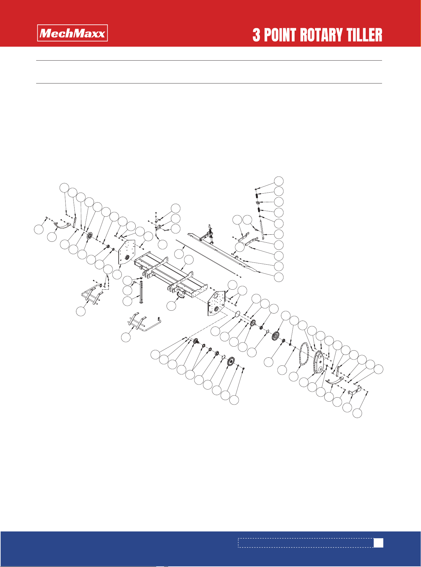
LRT42/45/48/53 PARTS DIAGRAM (TILLER HOOD ASSEMBLY)
LRT42/45/48/53 PARTS DIAGRAM (TILLER HOOD ASSEMBLY)
1
24
3
5
25
4
12
6
26
19
23
29
22
28
34
27
20
10
33
8
21
16
7
30
35
9
18
31
11
32
15
14
24
4
6
4
4
6
13
12
25
4
5
3
2
17

19
www.mechmaxx.com
LRT42/45/48/53 PARTS LIST (TILLER HOOD ASSEMBLY)
LRT42/45/48/53 PARTS LIST (TILLER HOOD ASSEMBLY)
16
16
2
10
2
4
1
1
1
1
1
1
1
1
1
1
1
1
1
1
1
2
2
1
1
1
17
1
1
No. DESCRIPTION Qty
1
2
3
4
5
6
7
8
9
10
11
12
13
14
15
16
17
18
19
Lock Nut M12
Flat Washer M12
Rear Adjustment Plate
Hex Bolt M12 × 35
Rear Soil Shield Plate
Hex Bolt M12 × 40
Grease Fitting M8 × 1
Right Side Plate Weldment
Hood Weldment
Rear Shield Weldment
Tension Bar
Hex Bolt M12 × 45
Shield Shaft Weldment
Flat Washer M10
Lock Nut M10
Roller Chain 16A × 34 Links
Lock Nut M8
Breather Plug M16 × 1.5
Side Cover Weldment
Remarks
85
95
105
115
125
135
85
95
105
115
125
135

20
www.mechmaxx.com
LRT42/45/48/53 PARTS LIST (TILLER HOOD ASSEMBLY)
14
1
34
3
2
2
1
1
1
1
1
1
1
1
1
1
1
1
1
1
1
1
1
1
0.4 m
1
No. DESCRIPTION Qty
20
21
22
23
24
25
26
27
28
29
30
31
32
33
34
35
Hex Bolt M8 × 25
Oil Level Plug M16 × 1.5
Flat Washer M8
Hex Bolt M8 × 35
Slide Rail Plate Weldment
Slide Rail Spacer Sleeve
Threaded Plug M16 × 1.5
Copper Washer M12
Hex Nut M12
Hex Bolt M12 × 60
Rubber Pad
Guard Weldment – Type 2
Side Plate Weldment
Guard Weldment – Type 1
Ø8 Chain
Ø8 Shackle
Remarks
85
95
105
115
125
135
85
95
105
115
125
135
12 Links
21
www.mechmaxx.com
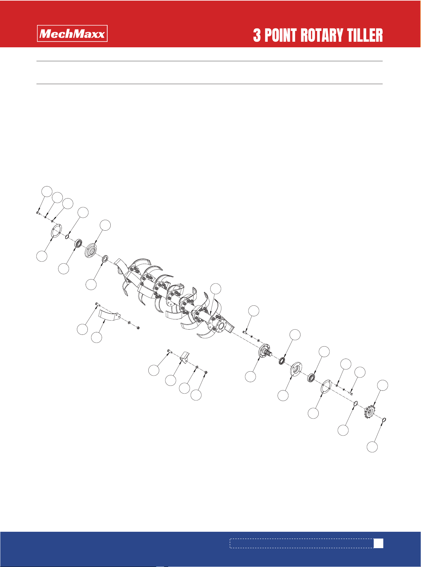
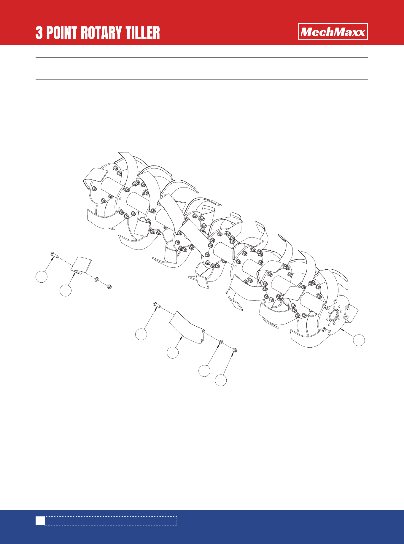
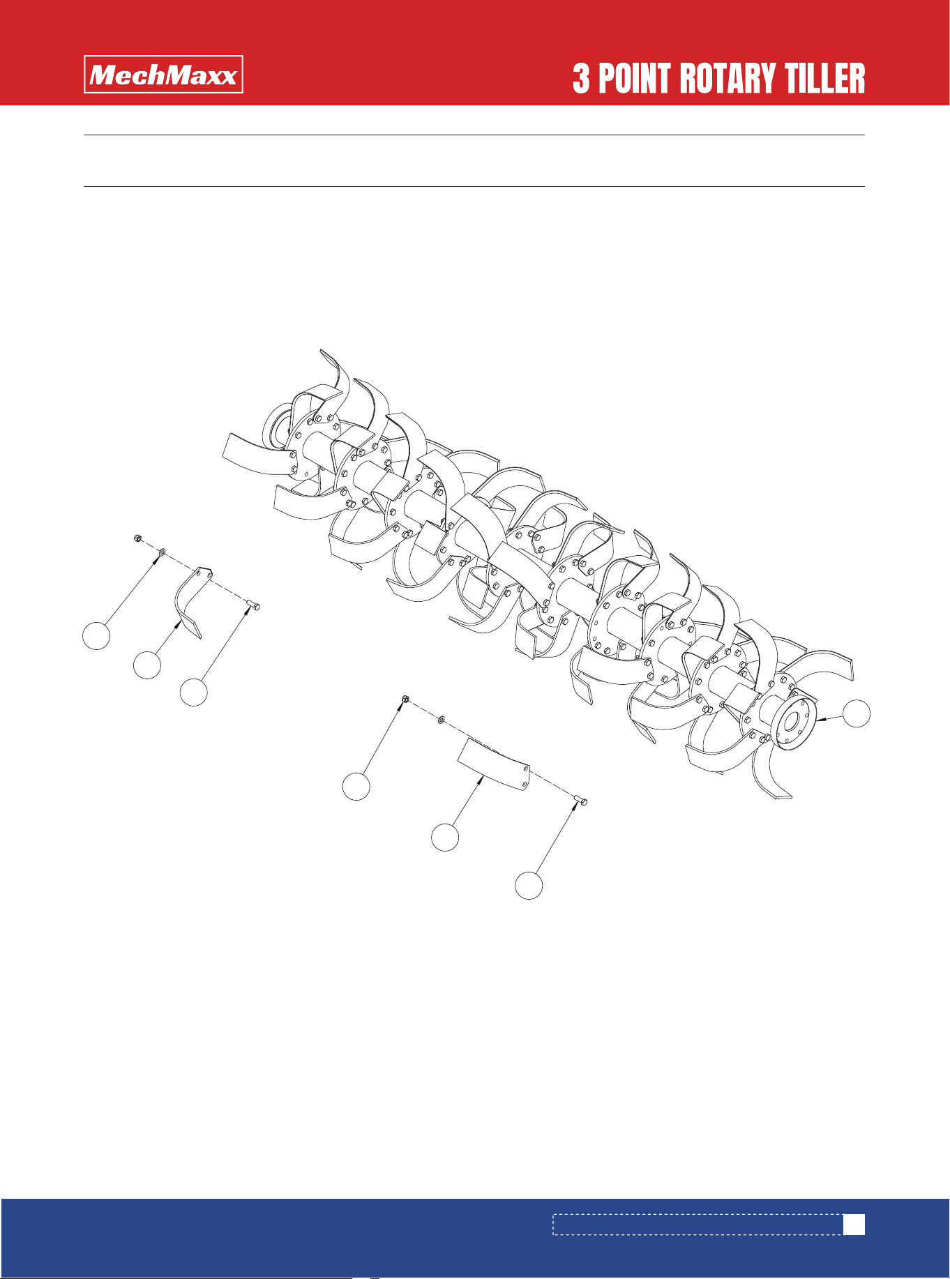
LRT42/45/48/53 PARTS DIAGRAM (ROTOR SHAFT ASSEMBLY)
LRT42/45/48/53 PARTS DIAGRAM (ROTOR SHAFT ASSEMBLY)
4
1
11
2
3
13
12
7
9
5
8
15
16
14
19
18
18
6
17
4
7
8
5
9
13
10
22
www.mechmaxx.com
LRT42/45/48/53 PARTS LIST (ROTOR SHAFT ASSEMBLY)
LRT42/45/48/53 PARTS LIST (ROTOR SHAFT ASSEMBLY)
4
16
12
2
2
1
1
1
1
1
1
12
2
2
4
1
1
2
1
32
40
40
48
56
56
32
40
40
48
No. DESCRIPTION Qty
1
2
3
4
5
6
6
6
6
6
6
7
8
9
10
11
12
13
14
15
16
Hex Bolt M10 × 25
Spring Washer M10
Flat Washer M10
Shaft Retaining Ring Ø34
Lower Bearing Housing
Rotor Shaft Weldment
Hex Bolt M10 × 30
Oil Seal 40 × 62 × 8
Deep Groove Ball Bearing 6207
Copper Washer M10
Driven Sprocket
Adjustment Shim – Type 2
Gasket
Splined Rotor Shaft End
Lock Nut M12
Flat Washer M12
Remarks
85
95
105
115
125
135
85
95
105
115
125
135
85
95
105
115

23
www.mechmaxx.com
56
56
8
10
10
12
14
14
32
40
40
48
56
56
8
10
10
12
14
14
No. DESCRIPTION Qty
17
18
19
Light-Duty Tiller Blade (LH)
Hex Bolt M12 × 35
Light-Duty Tiller Blade (RH)
Remarks
125
135
85
95
105
115
125
135
85
95
105
115
125
135
85
95
105
115
125
135
LRT42/45/48/53 PARTS LIST (ROTOR SHAFT ASSEMBLY)
24
www.mechmaxx.com
MRT48/60/72 PARTS LIST
1
1
1
1
No. DESCRIPTION Qty
1
2
3
4
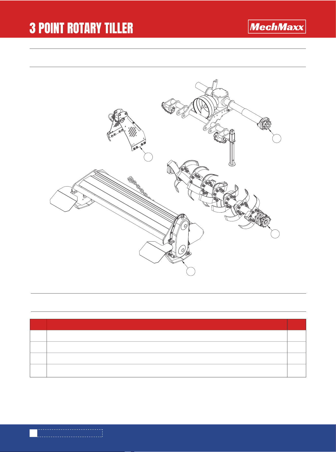
3-Point Hitch Assembly
Gearbox Assembly
Tiller Hood Assembly
Rotor Shaft Assembly
MRT48/60/72 PARTS DIAGRAM
MRT48/60/72 PARTS DIAGRAM
1
2
3
4
25
www.mechmaxx.com
MRT48/60/72 PARTS DIAGRAM (3-POINT HITCH ASSEMBLY)
MRT48/60/72 PARTS DIAGRAM (3-POINT HITCH ASSEMBLY)
MRT48/60/72 PARTS LIST (3-POINT HITCH ASSEMBLY)
2
2
1
2
2
1
1
1
6
1
6
6
No. DESCRIPTION Qty
1
2
3
4
5
6
7
8
9
10
11
12
Hex Bolt M6 × 25
Flat Washer M6
Operator’s Manual Tube
Heavy Flat Washer M6
Lock Nut M6
Upper Hitch Pin
Hitch Spacer Sleeve
Hitch Hook
Hex Bolt M16 × 50
Upper Hitch Weldment
Flat Washer M16
Lock Nut M16
1
12
6
10
11
2
3
8
7
9
4
5
26
www.mechmaxx.com
MRT48/60/72 PARTS DIAGRAM (GEARBOX ASSEMBLY)
MRT48/60/72 PARTS DIAGRAM (GEARBOX ASSEMBLY)
1
32
21
33
3
22
31
10
2
19
5
23
6
18
12
24
17
13
26
25
15
14
4
9
11
8
21
28
27
7
4
35
29
34
30
16
20
20

27
www.mechmaxx.com
MRT48/60/72 PARTS LIST (GEARBOX ASSEMBLY)
MRT48/60/72 PARTS LIST (GEARBOX ASSEMBLY)
4
4
1
1
1
1
1
1
1
1
14
14
1
1
1
1
1
1
1
1
8
8
8
8
1
1
1
1
1
90
105
125
135
150
160
170
180
90
105
125
135
150
No. DESCRIPTION Qty
1
2
3
4
5
6
7
8
9
10
11
12
13
14
15
16
17
18
Hex Bolt M10 × 35
Lock Nut M10
Right Connecting Tube Weldment
Hex Bolt M10 × 25
Spring Washer M10
Breather Plug ZG3/8
Gearbox Assembly
Input Gear
Internal Retaining Ring Ø110
End Cap 110 × 12
Tapered Roller Bearing 30310
Plug ZG1/4
Oil Seal 42 × 75 × 12
Lock Nut M12
Flat Washer M12
Copper Washer Ø12
Hex Bolt M12 × 40
Gearbox Output Shaft (Long)
Remarks

28
www.mechmaxx.com
MRT48/60/72 PARTS LIST (GEARBOX ASSEMBLY)
1
1
1
1
2
2
1
1
1
1
1
1
1
1
1
1
1
1
1
1
1
1
22
4
1
1
1
160
170
180
90
105
125
135
150
160
170
180
No. DESCRIPTION Qty
19
20
21
22
23
24
25
26
27
28
29
30
31
32
33
34
35
Tapered Roller Bearing 31308
Lock Washer Round Nut M30
Round Nut M30 × 1.5
Side Drive Gear
Oil Seal 40 × 70 × 12
Paper Gasket (2 mm)
Drive Shaft Tube Weldment
Paper Gasket (1 mm)
Tapered Roller Bearing 30311
Output Gear
Tapered Roller Bearing 30208
Oil Seal 40 × 80 × 12
Flat Washer M10
Hex Bolt M10 × 25
Cover Weldment
Internal Retaining Ring Ø80
Input Shaft
Remarks
29
www.mechmaxx.com
MRT48/60/72 PARTS DIAGRAM (TILLER HOOD ASSEMBLY)
MRT48/60/72 PARTS DIAGRAM (TILLER HOOD ASSEMBLY)
13
38
37
1
2
39
3
32
36
14
42
41
4
35
43
15
16
57
56
8
11
20
34
21
18
12
58
53
67
23
31
19
33
44
55
66
30
54
28
65
24
29
64
45
63
59
46
60
48
52
25
26
50
51
49
13
14
13
20
13
13
13
5
5
6
10
7
2
1
9
13
18
35
28
32
39
20
61
62
17
22
18
47
27
40
40
27

30
www.mechmaxx.com
MRT48/60/72 PARTS LIST (TILLER HOOD ASSEMBLY)
MRT48/60/72 PARTS LIST (TILLER HOOD ASSEMBLY)
4
4
2
2
4
4
8
1
1
1
1
1
1
1
1
4
2
2
2
11
2
4
4
26
15
1
10
4
12
90
105
125
135
150
160
170
180
No. DESCRIPTION Qty
1
2
3
4
5
6
7
8
9
10
11
12
13
14
15
16
17
18
19
20
21
22
Spring Washer
Compression Spring
Spring Compression Sleeve
Support Tube Weldment
Rear Shield Connector Plate
Hex Bolt M12 × 55
Lock Nut M14
Rear Shield Weldment
R-Clip Pin Ø6 × 45
Hex Bolt M14 × 45
Clamp
Clamp Weldment
Hex Bolt M12 × 40
Adjustment Plate
Hex Bolt M10 × 20
Spring Washer M10
Flat Washer M10
Hex Bolt M12 × 35
Heavy Flat Washer M12
Hex Bolt M14 × 40
Spring Washer M14
Flat Washer M14
Remarks

31
www.mechmaxx.com
MRT48/60/72 PARTS LIST (TILLER HOOD ASSEMBLY)
1
1
1
1
1
1
1
1
1
1
1
1
1
1
1
1
1
2
4
2
1
1
7
15
1
1
2
18
22
1
2
2
90
105
125
135
150
160
170
180
90
105
125
135
150
160
170
180
No. DESCRIPTION Qty
23
24
25
26
27
28
29
30
31
32
33
34
35
36
37
38
39
40
Rear Shield Pin
Hood Weldment
Left Large Side Plate Weldment
Fine Thread Bolt M12 × 1.25 × 35
Copper Washer Ø12
Deep Groove Ball Bearing 6208
Side Intermediate Gear
Round Nut M36 × 1.5
Hex Bolt M10 × 35
Hex Bolt M10 × 30
Breather Plug M16 × 1.5
Oil Level Plug M16 × 1.5
Round Nut M30 × 1.5
Lock Nut M12
Lock Nut M10
Guard Plate
Slide Rail Plate Weldment
Lock Washer Round Nut M30
Remarks

32
www.mechmaxx.com
MRT48/60/72 PARTS LIST (TILLER HOOD ASSEMBLY)
1
1
1
1
1
1
2
1
2
2
2
2
1
1
1
1
1
1
1
1
1
1
1
1
1
1
1
1
1
1
1
1
90
105
125
135
150
160
170
180
90
105
125
135
150
160
170
No. DESCRIPTION Qty
41
42
43
44
45
46
47
48
49
50
51
52
53
54
55
56
57
58
59
Threaded Plug M16 × 1.5
Side Gear Guard Weldment
Rubber Pad
O-Ring 28 × 3.55
Internal Retaining Ring Ø80
Intermediate Shaft End
Fine Thread Bolt M12 × 1.25 × 30
O-Ring 145 × 3.55
Lower Hitch Pin
Parking Stand Weldment
D-Type Square Pin 12 × 70
Square Tube End Cap 40
Right Large Side Plate Weldment
Oil Seal 35 × 62 × 8
Deep Groove Ball Bearing 6306
Oil Seal Cover Weldment
Grease Fitting M8 × 1
Left Safety Guard Weldment
Right Safety Guard Weldment
Remarks

33
www.mechmaxx.com
MRT48/60/72 PARTS LIST (TILLER HOOD ASSEMBLY)
1
8
26
39
1
2
1
1
1
180
No. DESCRIPTION Qty
60
61
62
63
64
65
66
67
Hex Bolt M12 × 25
Spring Washer M12
Flat Washer M12
Third Shaft
Oil Seal 55 × 80 × 8
Deep Groove Ball Bearing 6309
Internal Retaining Ring Ø100
Side Driven Gear
Remarks
MRT48/60/72 PARTS DIAGRAM (ROTOR SHAFT ASSEMBLY)
34
www.mechmaxx.com
5
2
3
6
4
1
5
MRT48/60/72 PARTS DIAGRAM (ROTOR SHAFT ASSEMBLY)

MRT48/60/72 PARTS LIST (ROTOR SHAFT ASSEMBLY)
1
1
1
1
1
1
1
1
48
60
72
72
84
84
96
96
48
60
72
72
84
84
96
96
12
15
18
18
21
90
105
125
135
150
160
170
180
90
105
125
135
150
160
170
180
90
105
125
135
150
160
170
180
90
105
125
135
150
No. DESCRIPTION Qty
1
2
3
4
Rotor Shaft Weldment
Lock Nut M12
Flat Washer M12
Rotary Tiller Blade – Type B
Remarks
35
www.mechmaxx.com
MRT48/60/72 PARTS LIST (ROTOR SHAFT ASSEMBLY)

21
24
24
48
60
72
72
84
84
96
96
12
15
18
18
21
21
24
24
160
170
180
90
105
125
135
150
160
170
180
90
105
125
135
150
160
170
180
No. DESCRIPTION Qty
5
6
Hex Bolt M12 × 35
Rotary Tiller Blade – Type A
Remarks
36
www.mechmaxx.com
MRT48/60/72 PARTS LIST (ROTOR SHAFT ASSEMBLY)
HRT80/90 PARTS LIST
1
1
1
1
No. DESCRIPTION Qty
1
2
3
4
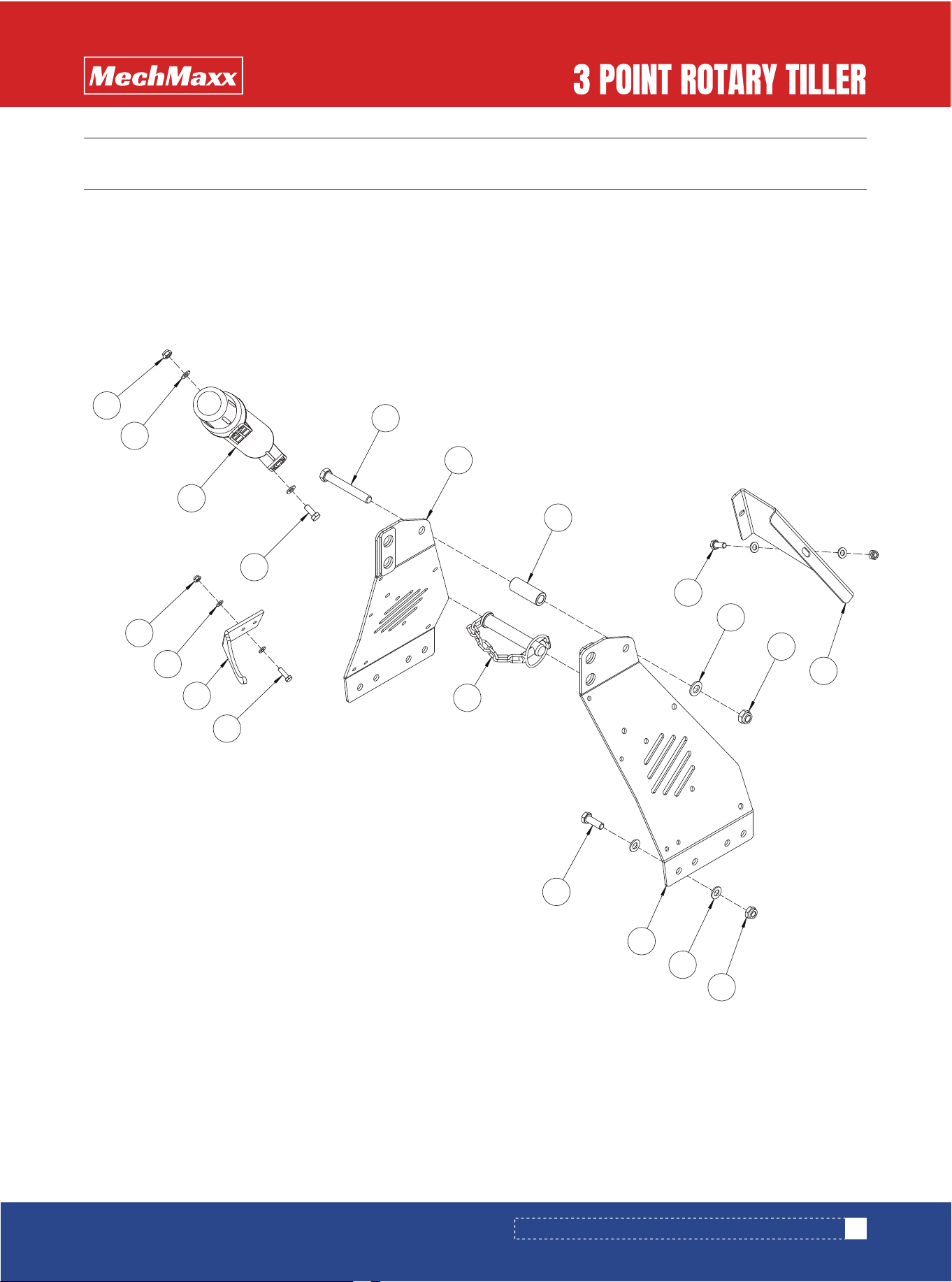
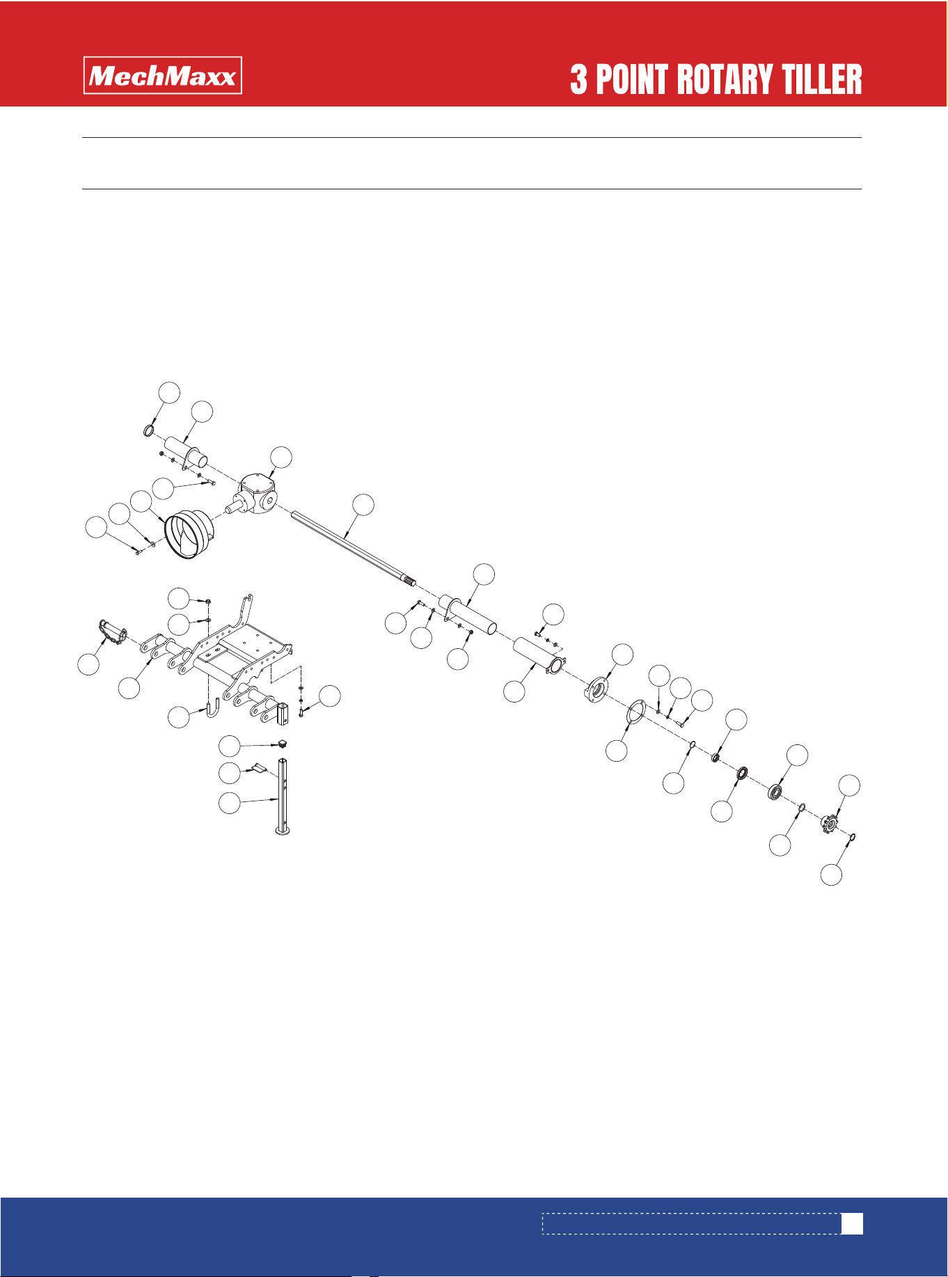
3-Point Hitch Assembly
Gearbox Assembly
Tiller Hood Assembly
Blade Shaft Assembly
HRT80/90 PARTS DIAGRAM
37
www.mechmaxx.com
1
3
4
2
HRT80/90 PARTS DIAGRAM
HRT80/90 PARTS DIAGRAM (3-POINT HITCH ASSEMBLY)
38
www.mechmaxx.com
1
2
12
14
9
7
13
3
15
17
16
8
4
5
10
11
6
8
HRT80/90 PARTS DIAGRAM (3-POINT HITCH ASSEMBLY)

HRT80/90 PARTS LIST (3-POINT HITCH ASSEMBLY)
2
2
1
2
2
1
1
6
1
8
8
4
4
2
2
4
2
No. DESCRIPTION Qty
1
2
3
4
5
6
7
8
9
10
11
12
13
14
15
16
17
Hex Bolt M6 × 25
Flat Washer M6
Operator’s Manual Tube
Heavy Flat Washer M6
Lock Nut M6
Upper Hitch Pin
Hitch Hook
Hex Bolt M16 × 45
Upper Hitch Weldment
Flat Washer M16
Lock Nut M16
Lock Nut M12
Flat Washer M12
Clamp Weldment
Clamp
Hex Bolt M12 × 55
Hex Bolt M16 × 55
39
www.mechmaxx.com
HRT80/90 PARTS LIST (3-POINT HITCH ASSEMBLY)
HRT80/90 PARTS DIAGRAM (GEARBOX ASSEMBLY)
40
www.mechmaxx.com
34
1
33
21
38
32
2
3
37
26
24
4
27
25
4
5
6
7
10
11
14
12
13
29
11
14
36
30
35
22
15
28
16
20
17
4
9
31
8
20
19
23
18
23
HRT80/90 PARTS DIAGRAM (GEARBOX ASSEMBLY)

HRT80/90 PARTS LIST (GEARBOX ASSEMBLY)
4
12
12
24
24
1
1
1
1
1
2
1
1
3
1
1
1
8
8
2
1
2
2
1
1
1
1
1
1
180
200
210
220
230
No. DESCRIPTION Qty
1
2
3
4
5
6
7
8
9
10
11
12
13
14
15
16
17
18
19
20
21
22
23
24
25
Hex Bolt M12 × 45
Flat Washer M12
Lock Nut M12
Hex Bolt M10 × 25
Spring Washer M10
End Cap 140 × 15
Gearbox Assembly
Breather Plug ZG3/8
Shaft Retaining Ring Ø45
Input Gear
Tapered Roller Bearing 30308
Internal Retaining Ring Ø90
End Cap 90 × 12
Shim 90 × 76 × 1
Output Gear
Tapered Roller Bearing 30310
Paper Gasket (2 mm)
Copper Washer Ø12
Hex Bolt M12 × 40
Oil Seal 50 × 75 × 12
Side Drive Gear
Round Nut M40 × 1.5
Lock Washer for Round Nut M40
Tapered Roller Bearing 32210
Gearbox Output Shaft (Long)
Remarks
41
www.mechmaxx.com
HRT80/90 PARTS LIST (GEARBOX ASSEMBLY)
1
1
1
1
1
1
1
1
1
2
4
4
1
1
1
1
1
1
1
1
1
180
200
210
220
230
180
200
210
220
230
No. DESCRIPTION Qty
26
27
28
29
30
31
32
33
34
35
36
37
38
Shaft End Paper Gasket
Shaft Sleeve Weldment
Shim 62 × 50 × 1
Input Shaft
Gearbox Cover Gasket
Hex Socket Plug ZG3/8
Heavy Flat Washer M8
Hex Bolt M8 × 16
Cover Weldment
Gearbox Cover
Oil Seal 40 × 72 × 10
Right Gearbox Support Weldment
Mounting Plate
Remarks
42
www.mechmaxx.com
HRT80/90 PARTS LIST (GEARBOX ASSEMBLY)
HRT80/90 PARTS DIAGRAM (TILLER HOOD ASSEMBLY)
43
www.mechmaxx.com
39
11
37
59
12
38
13
58
14
40
57
15
1
56
41
16
60
17
35
55
33
54
72
70
43
18
69
30
68
29
20
67
21
19
66
44
28
10
45
65
61
63
46
26
53
50
47
22
48
62
24
52
49
27
42
8
41
64
23
18
19
7
2
4
3
5
9
8
7
6
8
17
3
51
31
32
36
25
34
71
HRT80/90 PARTS DIAGRAM (TILLER HOOD ASSEMBLY)

HRT80/90 PARTS LIST (TILLER HOOD ASSEMBLY)
4
4
8
4
4
4
8
16
2
2
2
2
2
4
4
4
28
1
1
1
6
2
4
1
1
1
1
1
180
200
210
220
230
180
200
210
220
230
No. DESCRIPTION Qty
1
2
3
4
5
6
7
8
9
10
11
12
13
14
15
16
17
18
19
20
Lock Nut M24
Flat Washer M24
Compression Spring
Spring Retainer Sleeve
Spring Link Weldment
Hex Bolt M10 × 50
Rear Deflector Connector Plate
Hex Bolt M14 × 55
Rear Deflector Weldment
Small Spacer
Hex Bolt M10 × 20
Spring Washer M10
Flat Washer M10
Hex Bolt M12 × 30
Shaft End Shim
Deep Groove Ball Bearing 6309
Hex Bolt M14 × 40
Deflector Connector Plate
Hex Bolt M12 × 40
Rear Deflector Support Rod
Remarks
44
www.mechmaxx.com
HRT80/90 PARTS LIST (TILLER HOOD ASSEMBLY)

1
1
1
1
1
1
8
4
4
1
1
1
4
16
1
1
24
1
1
1
22
26
1
1
4
1
1
1
1
1
1
1
180
200
210
220
230
No. DESCRIPTION Qty
21
22
23
24
25
26
27
28
29
30
31
32
33
34
35
36
37
38
39
40
41
42
43
44
45
46
47
48
Hood Weldment
Left Side Plate Weldment
Lock Nut M12
Hex Bolt M12 × 1.5 × 40
Copper Washer Ø12
Tapered Roller Bearing 32911
Side Intermediate Gear
Round Nut M50 × 1.5
Hex Bolt M10 × 40
Hex Bolt M10 × 35
Breather Plug M16 × 1.5
Oil Level Plug M16 × 1.5
Lock Nut M10
Lock Washer Round Nut M48
Round Nut M48 × 1.5
Hex Socket Plug M16 × 1.5
Lock Nut M14
Flat Washer M14
Protective Guard Plate
Right Slide Rail Plate Weldment
Hex Bolt M14 × 50
Side Cover Weldment
Rubber Pad
O-Ring 48 × 3.55
Tapered Roller Bearing 32010
Internal Retaining Ring Ø80
Intermediate Shaft End
O-Ring 145 × 3.55
Remarks
45
www.mechmaxx.com
HRT80/90 PARTS LIST (TILLER HOOD ASSEMBLY)

2
2
2
4
2
1
1
1
8
1
1
1
1
1
1
1
1
1
1
1
1
1
7
15
1
2
1
1
1
1
1
1
180
200
210
220
230
180
200
210
220
230
No. DESCRIPTION Qty
49
50
51
52
53
54
55
56
57
58
59
60
61
62
63
64
65
66
67
68
69
70
71
72
Category II Lower Hitch Pin
Parking Stand Weldment
Square Tube End Cap 40
Hex Bolt M12 × 45
D-Type Square Pin 12 × 70
Right Side Plate Weldment
Oil Seal 55 × 80 × 8
Internal Retaining Ring Ø100
Spring Washer M12
Oil Seal Cover Weldment
Grease Zerk M8 × 1
Left Slide Rail Plate Weldment
Left Safety Guard Weldment
Right Safety Guard Weldment
Hex Bolt M12 × 35
Flat Washer M12
Blade Shaft End
Oil Seal 60 × 80 × 8
Deep Groove Ball Bearing 6310
Internal Retaining Ring Ø110
Shaft End Spacer
Side Driven Gear
Lock Washer Round Nut M40
Round Nut M40 × 1.5
Remarks
46
www.mechmaxx.com
HRT80/90 PARTS LIST (TILLER HOOD ASSEMBLY)
HRT80/90 PARTS DIAGRAM (BLADE SHAFT ASSEMBLY)
47
www.mechmaxx.com
2
3
2
4
1
5
6
HRT80/90 PARTS DIAGRAM (BLADE SHAFT ASSEMBLY)

HRT80/90 PARTS LIST (BLADE SHAFT ASSEMBLY)
1
1
1
1
1
96
108
108
120
120
24
27
27
30
30
96
108
108
120
120
24
27
27
30
30
96
108
108
120
120
180
200
210
220
230
180
200
210
220
230
180
200
210
220
230
180
200
210
220
230
180
200
210
220
230
180
200
210
220
230
No. DESCRIPTION Qty
1
2
3
4
5
6
Rotor Shaft Weldment
Hex Bolt M12 × 35
Heavy-Duty Left Tine
Lock Nut M12
Heavy-Duty Right Tine
Flat Washer M12
Remarks
48
www.mechmaxx.com
HRT80/90 PARTS LIST (BLADE SHAFT ASSEMBLY)