MAC Ultra Performance
User Guide and Safety/Installation Manual

User Documentation update information
All important changes in the MAC Ultra Performance User Guide are listed below.
Revision H
Added Compact DMX Mode. Covers fixture firmware 2.3.x.
Revision G
Added Framing Mode. Covers fixture firmware 2.2.x.
Revision F
User documentation restructure (multi-language Safety/Installation Manual, single-language combined User and
Safety/Installation Manuals).
Revision E
Covers update to firmware v.2.0.0. Added continuous gobo wheel scrolling, Extended Gamut color mode and new
calibration options.
Revision D
Covers features in MAC Ultra Performance firmware version 1.6.0 such as Color Mode. Added drawing explaining
DMX values and pan/tilt/zoom/focus positions.
Revision C
Covers MAC Ultra Performance firmware version 1.5.0. Added pre-programmed FX (controllable via DMX). Added
Extended DMX Mode. Added info on cold start behavior. Keylight calibration available in control panel and via RDM.
Added note on CMY flag speed limitations when using P3 control. Some changes in control menu options.
Revision B
Covers MAC Ultra Performance firmware version 1.2.0. Added PWM frequency adjustment, details of cold start vs.
steady state output level. Minor corrections including corrections to followspot functionality.
Revision A
First version released. Covers MAC Ultra Performance firmware version 1.0.0
©2020-2026 HARMAN PROFESSIONAL DENMARK ApS. All rights reserved. Features, specifications and appearance are subject
to change without notice. HARMAN PROFESSIONAL DENMARK ApS and all affiliated companies disclaim liability for any injury,
damage, direct or indirect loss, consequential or economic loss or any other loss occasioned by the use of, inability to use or reliance
on the information contained in this document. Martin is a registered trademark of HARMAN PROFESSIONAL DENMARK ApS
registered in the United States and/or other countries.
HARMAN PROFESSIONAL DENMARK ApS
, Olof Palmes Allé 44, 8200 Aarhus N, Denmark
HARMAN PROFESSIONAL, INC.
, 8500 Balboa Blvd., Northridge CA 91325, USA
www.martin.com
MAC Ultra Performance User Guide and Safety/Installation Manual, P/N 5131481-00 Revision H

Contents
Introduction . . . . . . . . . . . . . . . . . . . . . . . . . . . . . . . . . . . . . . . . . . . . . . . . . . . . . . . . . . . . . . . . . . . . . . . . 4
Operating the fixture . . . . . . . . . . . . . . . . . . . . . . . . . . . . . . . . . . . . . . . . . . . . . . . . . . . . . . . . . . . . . . . . 5
Effects . . . . . . . . . . . . . . . . . . . . . . . . . . . . . . . . . . . . . . . . . . . . . . . . . . . . . . . . . . . . . . . . . . . . . . . . . . . . . 6
Shutter and strobe effects . . . . . . . . . . . . . . . . . . . . . . . . . . . . . . . . . . . . . . . . . . . . . . . . . . . . . . . . . . . . 6
Dimming. . . . . . . . . . . . . . . . . . . . . . . . . . . . . . . . . . . . . . . . . . . . . . . . . . . . . . . . . . . . . . . . . . . . . . . . . . 6
Color mixing. . . . . . . . . . . . . . . . . . . . . . . . . . . . . . . . . . . . . . . . . . . . . . . . . . . . . . . . . . . . . . . . . . . . . . . 6
Color temperature control . . . . . . . . . . . . . . . . . . . . . . . . . . . . . . . . . . . . . . . . . . . . . . . . . . . . . . . . . . . . 6
Color wheel . . . . . . . . . . . . . . . . . . . . . . . . . . . . . . . . . . . . . . . . . . . . . . . . . . . . . . . . . . . . . . . . . . . . . . . 6
Rotating gobos. . . . . . . . . . . . . . . . . . . . . . . . . . . . . . . . . . . . . . . . . . . . . . . . . . . . . . . . . . . . . . . . . . . . . 7
Animation wheel . . . . . . . . . . . . . . . . . . . . . . . . . . . . . . . . . . . . . . . . . . . . . . . . . . . . . . . . . . . . . . . . . . . 9
Frost. . . . . . . . . . . . . . . . . . . . . . . . . . . . . . . . . . . . . . . . . . . . . . . . . . . . . . . . . . . . . . . . . . . . . . . . . . . . . 9
Optional heavy frost filters . . . . . . . . . . . . . . . . . . . . . . . . . . . . . . . . . . . . . . . . . . . . . . . . . . . . . . . . . . . . 9
Rotating prism . . . . . . . . . . . . . . . . . . . . . . . . . . . . . . . . . . . . . . . . . . . . . . . . . . . . . . . . . . . . . . . . . . . . . 9
Iris . . . . . . . . . . . . . . . . . . . . . . . . . . . . . . . . . . . . . . . . . . . . . . . . . . . . . . . . . . . . . . . . . . . . . . . . . . . . . . 9
Framing . . . . . . . . . . . . . . . . . . . . . . . . . . . . . . . . . . . . . . . . . . . . . . . . . . . . . . . . . . . . . . . . . . . . . . . . . 10
Zoom and focus . . . . . . . . . . . . . . . . . . . . . . . . . . . . . . . . . . . . . . . . . . . . . . . . . . . . . . . . . . . . . . . . . . . 10
Pan and tilt. . . . . . . . . . . . . . . . . . . . . . . . . . . . . . . . . . . . . . . . . . . . . . . . . . . . . . . . . . . . . . . . . . . . . . . 11
LED PWM frequency control . . . . . . . . . . . . . . . . . . . . . . . . . . . . . . . . . . . . . . . . . . . . . . . . . . . . . . . . . 11
Pre-programmed FX . . . . . . . . . . . . . . . . . . . . . . . . . . . . . . . . . . . . . . . . . . . . . . . . . . . . . . . . . . . . . . . 11
Control panel . . . . . . . . . . . . . . . . . . . . . . . . . . . . . . . . . . . . . . . . . . . . . . . . . . . . . . . . . . . . . . . . . . . . . 12
Control options. . . . . . . . . . . . . . . . . . . . . . . . . . . . . . . . . . . . . . . . . . . . . . . . . . . . . . . . . . . . . . . . . . . . 15
DMX. . . . . . . . . . . . . . . . . . . . . . . . . . . . . . . . . . . . . . . . . . . . . . . . . . . . . . . . . . . . . . . . . . . . . . . . . . . . 15
P3 video. . . . . . . . . . . . . . . . . . . . . . . . . . . . . . . . . . . . . . . . . . . . . . . . . . . . . . . . . . . . . . . . . . . . . . . . . 16
RDM. . . . . . . . . . . . . . . . . . . . . . . . . . . . . . . . . . . . . . . . . . . . . . . . . . . . . . . . . . . . . . . . . . . . . . . . . . . . 16
Fixture setup . . . . . . . . . . . . . . . . . . . . . . . . . . . . . . . . . . . . . . . . . . . . . . . . . . . . . . . . . . . . . . . . . . . . . . 19
Fixture ID . . . . . . . . . . . . . . . . . . . . . . . . . . . . . . . . . . . . . . . . . . . . . . . . . . . . . . . . . . . . . . . . . . . . . . . . 19
Personality . . . . . . . . . . . . . . . . . . . . . . . . . . . . . . . . . . . . . . . . . . . . . . . . . . . . . . . . . . . . . . . . . . . . . . . 19
Managing fixture settings. . . . . . . . . . . . . . . . . . . . . . . . . . . . . . . . . . . . . . . . . . . . . . . . . . . . . . . . . . . . 22
Fixture information readouts . . . . . . . . . . . . . . . . . . . . . . . . . . . . . . . . . . . . . . . . . . . . . . . . . . . . . . . . . 23
Temperatures . . . . . . . . . . . . . . . . . . . . . . . . . . . . . . . . . . . . . . . . . . . . . . . . . . . . . . . . . . . . . . . . . . . . 23
DMX signal monitoring. . . . . . . . . . . . . . . . . . . . . . . . . . . . . . . . . . . . . . . . . . . . . . . . . . . . . . . . . . . . . . 23
Test sequences . . . . . . . . . . . . . . . . . . . . . . . . . . . . . . . . . . . . . . . . . . . . . . . . . . . . . . . . . . . . . . . . . . . 23
Manual control . . . . . . . . . . . . . . . . . . . . . . . . . . . . . . . . . . . . . . . . . . . . . . . . . . . . . . . . . . . . . . . . . . . . 24
Service. . . . . . . . . . . . . . . . . . . . . . . . . . . . . . . . . . . . . . . . . . . . . . . . . . . . . . . . . . . . . . . . . . . . . . . . . . 24
Adjusting settings via DMX . . . . . . . . . . . . . . . . . . . . . . . . . . . . . . . . . . . . . . . . . . . . . . . . . . . . . . . . 25
Resetting . . . . . . . . . . . . . . . . . . . . . . . . . . . . . . . . . . . . . . . . . . . . . . . . . . . . . . . . . . . . . . . . . . . . . . . . 25
Illuminating the display . . . . . . . . . . . . . . . . . . . . . . . . . . . . . . . . . . . . . . . . . . . . . . . . . . . . . . . . . . . . . 25
Control menu setting overrides . . . . . . . . . . . . . . . . . . . . . . . . . . . . . . . . . . . . . . . . . . . . . . . . . . . . . . . 25
Adjusting calibration offsets via DMX . . . . . . . . . . . . . . . . . . . . . . . . . . . . . . . . . . . . . . . . . . . . . . . . . . 25
Adjusting keylight calibration via DMX. . . . . . . . . . . . . . . . . . . . . . . . . . . . . . . . . . . . . . . . . . . . . . . . . . 26
DMX protocol . . . . . . . . . . . . . . . . . . . . . . . . . . . . . . . . . . . . . . . . . . . . . . . . . . . . . . . . . . . . . . . . . . . . . 27
Basic Mode . . . . . . . . . . . . . . . . . . . . . . . . . . . . . . . . . . . . . . . . . . . . . . . . . . . . . . . . . . . . . . . . . . . . . . 27
Compact Mode . . . . . . . . . . . . . . . . . . . . . . . . . . . . . . . . . . . . . . . . . . . . . . . . . . . . . . . . . . . . . . . . . . . 34
Extended Mode . . . . . . . . . . . . . . . . . . . . . . . . . . . . . . . . . . . . . . . . . . . . . . . . . . . . . . . . . . . . . . . . . . . 35
FX: pre-programmed effects . . . . . . . . . . . . . . . . . . . . . . . . . . . . . . . . . . . . . . . . . . . . . . . . . . . . . . . 43
Control panel menus . . . . . . . . . . . . . . . . . . . . . . . . . . . . . . . . . . . . . . . . . . . . . . . . . . . . . . . . . . . . . . 48
Service and display messages. . . . . . . . . . . . . . . . . . . . . . . . . . . . . . . . . . . . . . . . . . . . . . . . . . . . . 53
Warning messages . . . . . . . . . . . . . . . . . . . . . . . . . . . . . . . . . . . . . . . . . . . . . . . . . . . . . . . . . . . . . . . . 53
Error messages . . . . . . . . . . . . . . . . . . . . . . . . . . . . . . . . . . . . . . . . . . . . . . . . . . . . . . . . . . . . . . . . . . . 54
Control orientation reference. . . . . . . . . . . . . . . . . . . . . . . . . . . . . . . . . . . . . . . . . . . . . . . . . . . . . . . 58
Pan and tilt control. . . . . . . . . . . . . . . . . . . . . . . . . . . . . . . . . . . . . . . . . . . . . . . . . . . . . . . . . . . . . . . . . 58
Zoom and focus control . . . . . . . . . . . . . . . . . . . . . . . . . . . . . . . . . . . . . . . . . . . . . . . . . . . . . . . . . . . . . 59

4
MAC Ultra Performance User Guide
Introduction
Warning! Before installing, operating or servicing the MAC Ultra Performance lighting fixture, read
the latest version of the fixture’s Safety and Installation Manual, paying particular attention to the
Safety Precautions section. The Safety and Installation Manual is supplied with the fixture and
included at the end of this User Guide. The latest version is also available for download from the
MAC Ultra Performance area of the Martin® website at www.martin.com.
Thank you for selecting a MAC Ultra Performance moving head lighting fixture from Martin®.
This User Guide is a supplement to the Safety and Installation Manual. This User Guide contains
information that is mainly of interest for lighting designers and operators, whereas the Safety and Installation
Manual contains important information for all users, especially installers and technicians.
We recommend that you check the Martin website regularly for updated documentation, because we
publish revised versions each time we can improve the quality of the information we provide and each time
we release new firmware with changes or new features. Each time we revise this guide we list any important
changes on page 2 so that you can keep track of updates.
The MAC Ultra Performance moving-head spotlight offers the following features:
• Bright 1150 W light engine
• Fixture output of 46 500 lumens
• High-contrast optics with flat field and low distortion
• Exceptionally low noise
• Full-range dimming with four dimming curve options
• Electronic shutter effect with variable speed regular and random strobe
• CMY color mixing
• Continuously variable Color Temperature Control from 6000 to 2850 K
• 6-slot color wheel including spectral enhancement filter for added color choice and split color effects
• Two rotating gobo wheels, each with 5 rotating gobos
• Gobo animation wheel that can be inserted horizontally, vertically and diagonally, with continuous
bi-directional rotation
• 4-blade rotating framing module with +/- 83° of movement and variable blade angle of 30° through full
insertion range
• 4-facet rotating prism
• Iris with continuous adjustment and pulse effects
• Variable frost for smooth wash effects
• Optional heavy frost filter replacement for prism
• Optional heavy frost filter replacement for standard frost filter
• 1:7 fast-action zoom
• Motorized focus with zoom/focus tracking option
• 540° of pan and 268° of tilt with user-settable pan and tilt limits
• Basic and Extended DMX Modes, with additional 16-bit control functions in Extended Mode
• Compact DMX Mode (from firmware v. 2.3.0) with 42-channel DMX footprint
• Wide range of pre-programmed dynamic FX
• Followspot functionality with integrated handles
• Standard DMX, Art-Net and sACN control, RDM monitoring and setup
• Integration with Martin P3 system controllers for video mapping of intensity, color or both
• Variable crossfading between DMX and video control
• Martin P3 system controllers feature remote setup, patching and monitoring
• Backlit graphic display
• Disposable lithium battery allowing fixture setup without mains power.

Introduction
5
Operating the fixture
Before applying power to or operating the MAC Ultra Performance:
• Read the ‘Safety Information’ section of the fixture’s Safety and Installation Manual that is included at the
end of this User Guide, supplied with the fixture and available for download from the Martin website at
www.martin.com.
• Check that the installation is safe and secure.
• If the fixture is moved from a cold to a warm environment, remove it from its flightcase or packaging and
give it at least two hours to acclimatize before applying power. This will help to avoid damage due to
condensation.
• Check that the fixture is in perfect condition. Do not apply power to a fixture that is obviously damaged, or
you may create a safety risk and make the damage worse.
• Check that the base is fastened securely so that the torque reaction when the head moves will not cause
the base to move.
• Check that the head tilt lock is released.
• Be prepared for the head to move suddenly. Check that there will be no risk of collision with persons or
objects.
• Be prepared for the fixture to light up suddenly. Check that no-one is looking at the fixture from close
range.
The fixture does not have an On/Off switch. To apply power to the fixture, connect the power input cable to a
source of AC power that is within the range 200-240 V (nominal), 50/60 Hz. The fixture’s Neutrik powerCON
TRUE1 TOP connectors can also be connected live or under load.
Note that whenever power is applied to the fixture, it will reset all effects and functions to their home
positions and the fixture head will move. This process takes several seconds.
Cold startup behavior
The fixture behaves as follows when starting up from cold:
• Luminous output at cold startup can be up to approximately 15% higher than the steady state output.
Output reaches the specified level when the fixture reaches its steady state temperature after
approximately 5 minutes (in Fan Regulated mode).
• Power to effects motors is increased until the internal temperature reaches 20°. For a short period this will
result in slightly more noise from CMY and other mechanical effects.
• The FAST mode in EFFECTS SPEED is only available when the fixture has warmed up. EFFECTS
SPEED is set to NORMAL during warmup.

6
MAC Ultra Performance User Guide
Effects
This section gives details of the effects available in the MAC Ultra Performance. See the DMX protocol table
on page 27 for a list of channels and commands used to control the effects via DMX.
Where fine control is available, the main control channel sets the first 8 bits (the most significant byte or
MSB), and the fine channels set the second 8 bits (the least significant byte or LSB) of the 16-bit control
byte. In other words, the fine channel works within the position set by the coarse channel.
Shutter and strobe effects
The fixture’s electronic shutter effect provides instant blackout and snap open as well as regular or random
strobe and pulse effects with variable speed from approx. 1 Hz to 20 Hz.
Dimming
Smooth 0-100% overall dimming is available with 16-bit control resolution. Four dimming curves are
available (see Figure 6 on page 20).
Color mixing
The fixture features dichroic CMY color filters, with 16-bit continuous color mixing available on six DMX
channels.
Color temperature control
16-bit color temperature control is available on two dedicated CTO channels. You can adjust the fixture’s
color temperature smoothly and continuously from 6000 K to 2850 K.
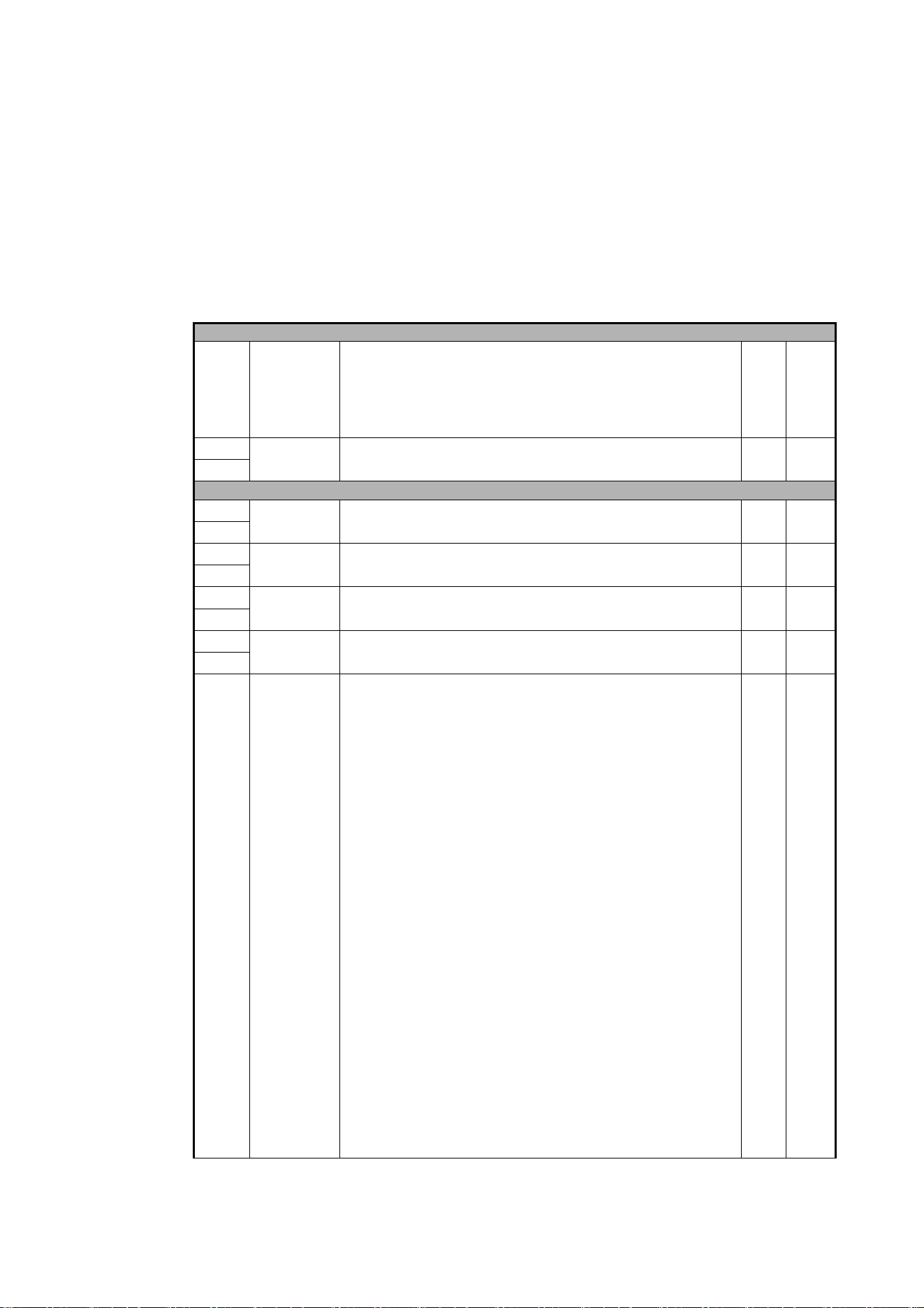
Color wheel
The fixture provides a
color wheel that lets
you select from six
dichroic color filters
plus open (see
Figure 1).
The color wheel can
be scrolled
continuously with
variable speed and
direction.
All color filters are
interchangeable.
Figure 1: Color wheel
Open
Orange
Deep Red
Navy Blue
500-544 SP
629 SP
440 SP
591 SP
Deep Green
Blue
508 SP
6
5
43
2
Wheel seen from LED side
Spectral
1
Enhancement
Effects
7
Rotating gobos
The gobos on Gobo Wheel 1 and 2 in the MAC Ultra Performance have the same dimensions and
specifications and are therefore interchangeable, but the goboholders on the two gobo wheels are different.
You cannot move a goboholder from one gobo wheel to the other.
We number gobo wheels in Martin fixtures in the order that the light from the source reaches them. In the
MAC Ultra Performance:
• The wheel closer to the LEDs is Gobo Wheel 1, the Aerial Wheel.
• The wheel closer to the front lens is Gobo Wheel 2, the Breakup Wheel.
Aerial Wheel – Gobo Wheel 1
The Aerial Wheel, Gobo Wheel 1, has five rotating gobos that can be used in any situation but are
especially suitable for midair effects. Gobos can be selected, indexed (positioned at an angle), rotated
continuously and shaken (bounced). Gobo selection and control type (indexing, continuous gobo rotation or
gobo shake – and from firmware v. 2.0.0 continuous gobo wheel scrolling) are set on channel 13.
Depending on what is selected on this channel, the gobo indexed angle or gobo rotation speed are set on
channels 14 and 15 with 16-bit control resolution.
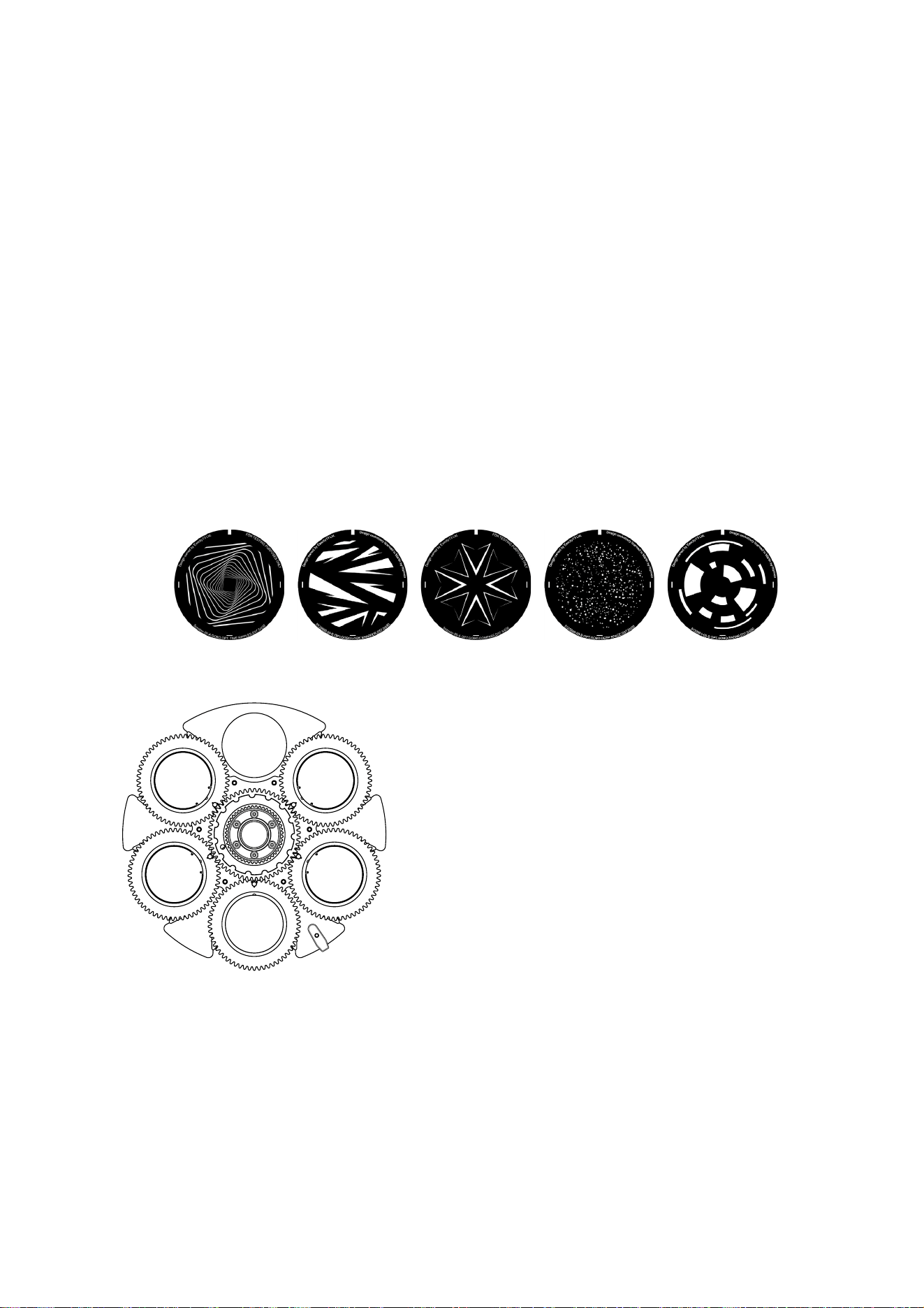
The standard gobos are shown in the correct order in Figure 2. All gobos are interchangeable. The MAC
Ultra Performance Safety and Installation Guide contains details of gobo replacement procedures.
Figure 2: Rotating gobos installed on Aerial Wheel as standard
Slot - Gobo Part number
1. Time Ripples .........................................P/N 5125897-00
2. Look Sharper ........................................P/N 5133660-00
3. Compass...............................................P/N 5125894-00
4. Deep Space ..........................................P/N 5125889-00
5. Radar ....................................................P/N 5133661-00
4
5
2
1
Aerial Wheel seen from LED side
12345
3
8
MAC Ultra Performance User Guide
Breakup Wheel – Gobo Wheel 2
The Breakup Wheel, Gobo Wheel 2, has five rotating gobos that can be used in any situation but are
especially suitable for breakup effects when used together with the animation wheel. Gobos can be
selected, indexed (positioned at an angle), rotated continuously and shaken (bounced). Gobo Wheel 2
selection and control type (indexing, continuous gobo rotation or gobo shake – and from firmware v. 2.0.0
continuous gobo wheel scrolling) are set on channel 16. Depending on what is selected on this channel, the
gobo indexed angle or gobo rotation speed are set on channels 17 and 18 with 16-bit control resolution.
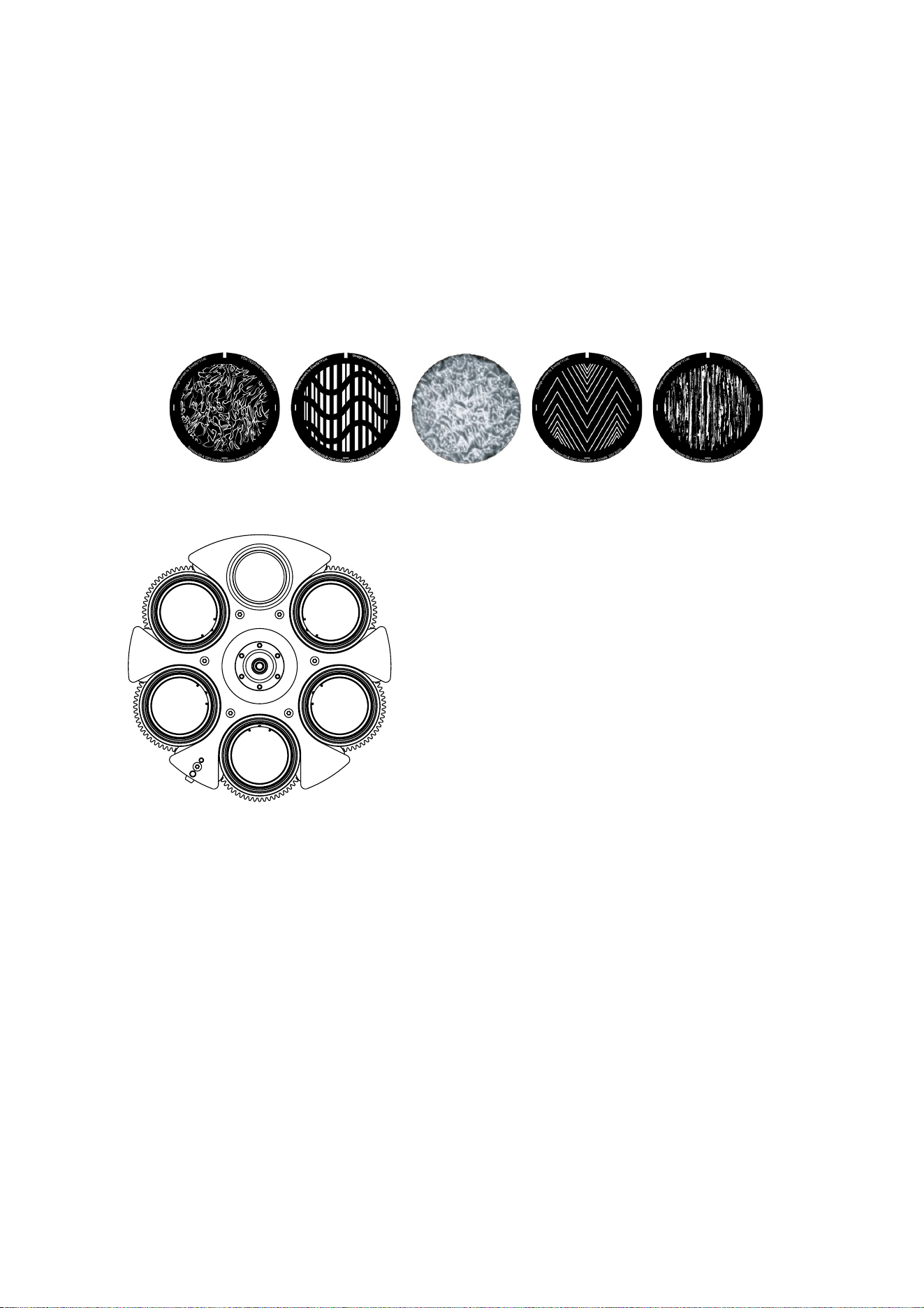
The standard gobos are shown in the correct order in Figure 3. All gobos are interchangeable except Gobo
3 (Limbo), which is fused glass and is glued into a special goboholder. The MAC Ultra Performance Safety
and Installation Guide contains details of gobo replacement procedures.
Figure 3: Rotating gobos installed on Breakup Wheel as standard
Slot - Gobo Part number
1. String Theory.......................................P/N 5125890-00
2. Hazey Waves ......................................P/N 5132626-00
3. Limbo* ..............................P/N 5123762-00 / 43043000
4. Up Is Down..........................................P/N 5125893-00
5. Brush Up .............................................P/N 5125891-00
* Limbo is a textured glass gobo glued into its holder
4
5
2
Breakup Wheel seen from LED side
1
3
12345

Effects
9
Animation wheel
The MAC Ultra Performance is supplied with
the “Worms That Turn” animation wheel
installed. The wheel can be used to add
animation effects to gobo projections.
When using gobo animation, adjust the
fixture’s focus to obtain the most realistic
results.
Frost
The fixture has a frost effect that can be
partially or fully inserted into the beam to
give a wash-type projection and soften gobo
outlines.
Note that using the frost effect at the
narrowest zoom angles will affect the zoom
lens position. From around 12° cutoff angle,
the frost effect does not affect the zoom
setting.
Optional heavy frost filters
An optional heavy frost filter, P/N MAR-91614060HU, MAC Ultra Heavy Frost - Prism Replacement, is
available as an accessory and can be installed in the fixture in place of the prism. As this frost effect is
heavy, it is not primarily intended for use together with gobos. Its main value is that it can soften the edges of
the framing blades or give a 'real' wash effect. As this filter replaces the prism, it has in/out operation – it is
not variable.
Another optional heavy frost filter accessory, P/N MAR-91614063HU, MAC Ultra Heavy Frost - Frost
Replacement can be installed in place of the standard frost filter. This option lets you keep the prism. As
with the standard frost filter, you can vary the extent to which this filter is inserted into the beam.
Installation of either of the two frost filters typically takes less than two minutes. The installation procedures
for the filters are covered in the MAC Ultra Performance Safety and Installation Manual supplied with the
fixture and available for download from www.martin.com.
Rotating prism
The MAC Ultra Performance has a four-facet circular prism that can be inserted into the beam at indexed
angles or rotated with variable direction and speed to give multiple beam effects.
Note that inserting the prism slightly reduces the narrowest zoom angle available.
Iris
The iris can be varied continuously to smoothly reduce the diameter of the beam. Opening and closing
pulse effects with variable speed are also available.
The iris can be controlled with 16-bit resolution in Extended DMX Mode.
Figure 4: ‘Worms That Turn’ animation wheel

10
MAC Ultra Performance User Guide
Framing
The MAC Ultra Performance’s framing module has 4 individually controllable framing blades with fully
variable angle of +/-30° through the entire insertion path from 0-100% (full curtain). The whole framing
module can rotate through +/-83°.
The framing blades have independent control of angle and amount of insertion for each blade. Adjusting
these parameters gives enormous flexibility in forming the beam into shapes of different sizes with three or
four sides. It is possible to angle the framing blades before inserting them into the beam – a feature unique
to this fixture that gives more creative possibilities.
With the fixture installed in a lighting rig with the head below the base and with the head the right way up,
the framing blades are numbered counting clockwise from the 12 o’clock position:
• Blade 1 = Top
• Blade 2 = Right
• Blade 3 = Bottom
• Blade 4 = Left
16-bit control of framing blade position and angle and 16-bit control of framing module angle are available in
Extended DMX Mode.
Two framing control modes are available from firmware v.2.2.x (see 'FRAMING MODE’ on page 22).
Zoom and focus
Adjusting focus lets you vary the sharpness of projected images at different distances. It can be particularly
effective when used together with gobos and the animation wheel.
The MAC Ultra Performance’s zoom lens varies the focused beam angle from 7.7° to 53°. Wide zoom
angles allow sharp focus on projection surfaces close to the fixture. At narrower zoom angles, sharp focus is
only possible further from the fixture.
If zoom is set to the narrowest position, it is not possible to focus on all effects at all distances. So when
Zoom/Focus tracking is disabled:
• You can find the narrowest zoom angle at which sharp focus is possible by setting focus to DMX value = 0,
then starting at the narrowest zoom angle and gradually moving towards wide until you achieve sharp
focus.
• At the widest zoom angle, simply set zoom to widest and adjust focus until you achieve sharp focus.
When Zoom/Focus tracking is enabled, we suggest that you set zoom to medium and then change the focus
setting until you achieve sharp focus with the desired effect. Changing the zoom angle will now
automatically change focus to keep a relatively sharp focus (some fine tuning may be necessary if you want
the sharpest focus). Not all effects can be in sharp focus at all zoom settings. At some combinations of
effect and distance, zooming to the widest or narrowest angles can cause loss of focus if the effect is no
longer within its focusable zoom range at that distance.
Zoom/focus linking
Focus varies with zoom angle, but focus can be linked to zoom so that it automatically adjusts to match
changes in zoom angle. Focus on rotating gobos matches zoom closely, while focus on the animation wheel
matches zoom best in the center of the zoom range and slightly less precisely at the two extremes of the
zoom range.
Linked zoom/focus works within 3 distance ranges: close-, medium- and long-range. The ranges are as
follows (figures are approximate):
• Close (5 - 10 meters / 16.5 - 33 ft.)
• Medium (10 - 20 meters / 33 - 66 ft.)
• Long (20 meters - infinity / 66 ft. -
∞)
To link zoom and focus, select a distance range using the Control/Settings DMX channel or FOCUS
TRACKING in the control panel PERSONALITY menu. Then adjust focus to obtain the required degree of
sharpness. Linking is now enabled and focus will auto-adjust to match changes in zoom angle.

Effects
11
Pan and tilt
The MAC Ultra Performance offers 540° of pan and 268° of tilt.
See the pan/tilt orientation reference drawings at the end of this user manual for a guide to the direction of
pan and tilt movement.
16-bit pan and tilt control are available. In each case, the second (LSB) DMX channel adjusts the position
set on the first (MSB) channel.
It is possible to set limits for the pan and tilt range (see details on page 19).
LED PWM frequency control
The PWM frequency of the MAC Ultra’s LEDs has been chosen carefully to avoid flickering on camera. In
some rare situations – for example when using cameras with non-standard settings – it may be necessary to
adjust the LED PWM frequency manually.
From firmware version 1.2.0, you can adjust the PWM frequency via DMX by sending value 255 on either
the FX1 Selection or the FX2 Selection channel. Once activated, the corresponding FX Speed and Direction
channel will control the LED PWM frequency. Note that this change is not stored permanently in the fixture,
so you have to keep the FX Selection and FX Speed/Direction channels at the chosen values in order to
keep the LED PWM frequency at the corresponding custom value.
You can adjust PWM frequency as follows:
High-speed PWM Frequency Mode drives the LEDs at 24 000 Hz. This frequency greatly reduces electronic
switching noise but it gives slightly faster cut-off at the low end of the dimming range.
The default PWM frequency is 3000 Hz.
Pre-programmed FX
From firmware version 1.5.0 the MAC Ultra Performance offers a range of pre-programmed effect macros
that we simply call FX. See a full description under “FX: pre-programmed effects” on page 43
FX give instant access to complex dynamic effects with no need for time-consuming programming at the
controller.
DMX value sent on FX Speed
and Direction channel LED PWM frequency
0 - 127 Adjustment in steps from 2400 to 3000 Hz
128 Default PWM frequency (3000 Hz)
129 - 254 No function
255 High-speed PWM Frequency Mode (24 000 Hz)
Table 1. PWM frequency adjustment values
12
MAC Ultra Performance User Guide
Control panel
You can configure individual fixture settings (such as the fixture’s DMX address), read out data, execute
service operations and view error messages using the fixture’s backlit graphic display and control panel.
When the MAC Ultra Performance is powered on, it first boots and resets, then it displays its DMX address
(or its fixture ID number, if one has been set) and any status messages (see page 53) in the display H.
The display can be set to automatically rotate to match standing or hanging fixture orientation in the
PERSONALITY → DISPLAY menu or the Shortcuts menu (see “Shortcuts” on page 13).
Using the control panel
• Press the MENU button C or Enter button E to access the menus.
• Use the UP and DOWN buttons D to scroll up and down menus.
• Press the ENTER button E to enter a menu or make a selection.
• The currently selected item in a menu is indicated by a star .
• Press the MENU button C to step backwards through the menus.
Status LED
The LED F next to the control buttons indicates fixture status by showing a color and DMX status by flashing
or lighting constantly:
• GREEN: All parameters normal.
• AMBER: Warning (service interval exceeded, for example).
If ERROR MODE is set to Normal, the warning message will be shown in the display. If ERROR MODE is
set to Silent, the display must be activated by pressing the Enter button C to display the warning
message.
• RED: Error detected.
-If ERROR MODE is set to NORMAL, the error message will be shown in the display.
-If ERROR MODE is set to SILENT, display the error message by entering the menus and going to
SERVICE
→ ERROR LIST.
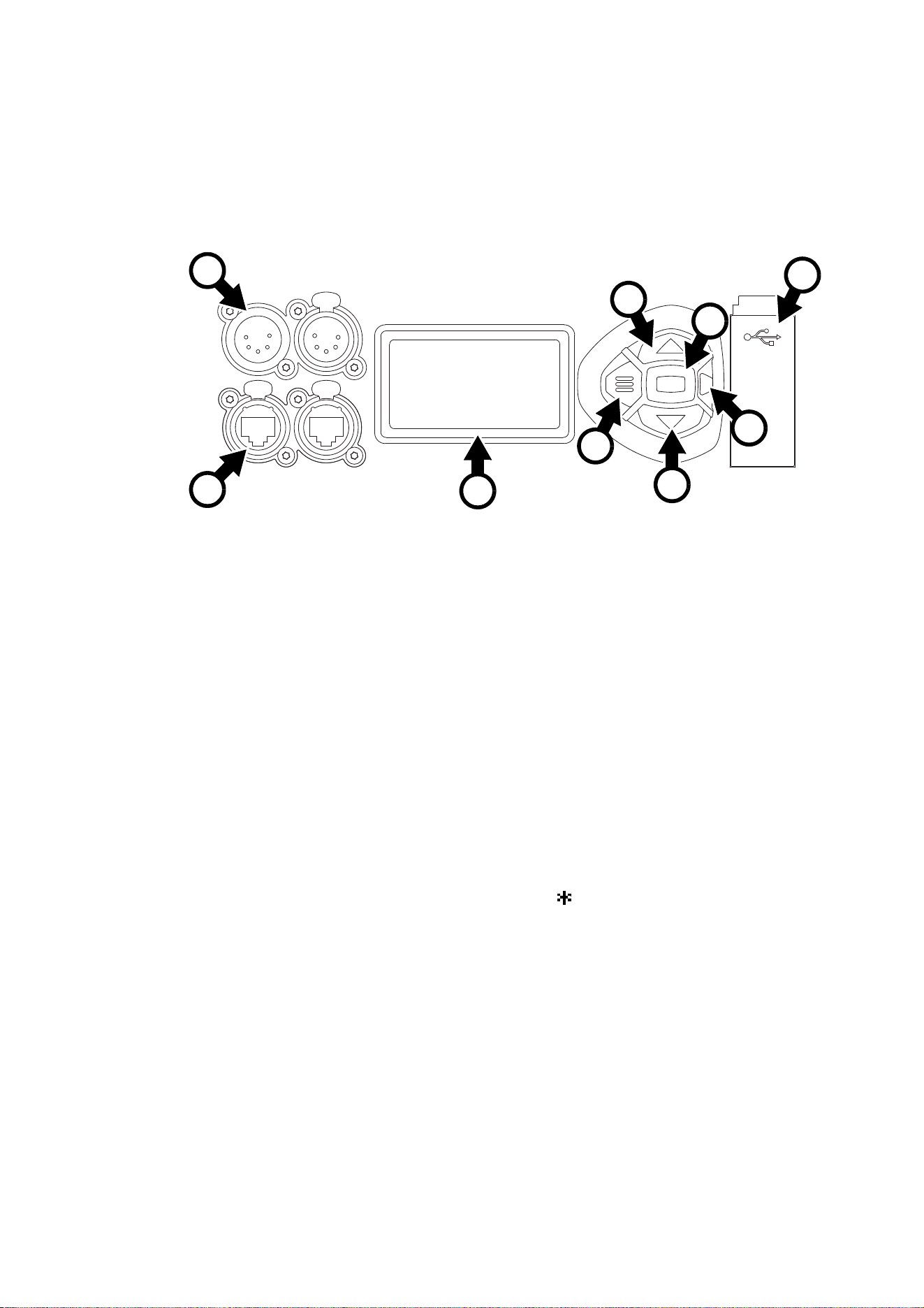
Figure 5: Display and control panel
1
DMX ADDRESS
DMX RANGE 1–48
B
F
D
A - XLR connectors
B - EtherCON connectors
C - Menu
D - Up/Down
E- Enter
F - Status LED
G - USB port / battery compartment
H - LCD display
A
G
C
E
D
H

Control panel
13
• FLASHING: No DMX signal detected.
• CONSTANT: Valid DMX signal detected.
The status LED remains active even if the display enters sleep mode.
Battery power
Warning! The fixture’s lithium battery is not rechargeable. Do not try to recharge it. If the battery is
discharged, obtain a replacement from your Martin supplier.
The MAC Ultra Performance contains a CR123A 3-volt lithium battery in a compartment G next to the
control panel. The battery gives access to the most important functions in the control panel when the fixture
is not connected to AC power. The following functions are available on battery power:
• DMX address
• DMX Mode (Basic or Extended)
• Fixture ID
• Personality settings (pan/tilt, cooling, fan clean mode, dimming curve, DMX reset, parameter shortcuts, all
display settings, error mode)
• Default settings
• Information (Power On Hours and Power Cycles counters, Software version)
• Error list
To activate the display when the fixture is not connected to power, press the MENU button C. Press again to
enter the menus. The display extinguishes after 10 seconds with no user input and the control panel is
de-activated after 1 minute with no user input. Press the MENU button C again to re-activate.
Shortcuts
If you hold the MENU button C pressed in for 2 - 3 seconds, a shortcut menu with the most important
commands appears. Select a command with the UP and DOWN buttons D and press the ENTER button E
to activate, or press the MENU button C again to cancel.
• RESET ALL resets the whole fixture
• ROTATE DISPLAY rotates the MAC Ultra Performance display 180°
• FOLLOWSPOT TOGGLE puts the fixture into / takes the fixture out of Followspot Mode (see
‘FOLLOWPOT MODE’ on page 19)
• TOGGLE HOLD POSITION uses the pan and tilt motors to hold the head in its current position – a feature
that is designed to be used in Followspot Mode when the operator wants to hold the head in a static
position for a period.
Settings stored permanently
The following settings are stored permanently in the fixture memory and are not affected by powering the
MAC Ultra Performance off and on or by updating the fixture software:
• DMX address
• DMX Mode
• Fixture ID
• Personality settings (pan/tilt, cooling, dimming curve, DMX reset, effect shortcuts, display settings, error
mode, etc.)
• Resettable and non-resettable counters
• Service settings (adjustment, calibration)
These settings can be returned to factory defaults using the control menus or via DMX.

14
MAC Ultra Performance User Guide
Activating service mode
Holding the MENU and ENTER buttons C and E both pressed in while powering the fixture on puts the
fixture into service mode, in which pan and tilt are disabled and a SERV warning appears in the display.
Service mode removes the risk of unexpected head movement during service adjustments.
To take the fixture out of SERVICE mode, power the fixture off, then reapply power and allow the fixture to
start normally.

Control options
15
Control options
You can control the MAC Ultra Performance using DMX and/or Martin P3 protocol. The fixture auto-senses
the type of data that it is receiving and will respond correctly with no need for manual protocol selection.
The following options are available:
• DMX control over standard DMX cable connected to the fixture’s 5-pin XLR connectors.
• DMX control using Art-Net over Ethernet cable connected to the fixture’s etherCON connectors.
• DMX control using streaming ACN over Ethernet cable connected to the fixture’s etherCON connectors.
• DMX control over DMX cable and P3 video data over Ethernet cable.
• P3 video data with embedded DMX commands over Ethernet cable. If you connect DMX / Art-Net / sACN
to the P3 system controller, the controller can merge the DMX commands into the P3 signal and send
them to the fixture over Ethernet.
The P3 Mix DMX channel lets you choose how the fixture should behave if it receives both DMX data and
P3 video data. You can use the P3 video pixel data to control the intensity and/or the color of the fixture’s
output with real-time control.
Fail-safe connection
The MAC Ultra Performance has a fail-safe network connection. If the fixture loses power or if you shut it
down, it will continue to relay an Ethernet signal, and the Art-Net / sACN / P3 signal to the other networked
fixtures in the daisy chain will not be interrupted.
Data rate
Any Ethernet switch used to relay Art-Net, streaming ACN or P3 data to the MAC Ultra Performance must
be capable of running at 10/100 Mbps speed, as the fixture does not support Gigabit Ethernet data rates.
DMX
The MAC Ultra Performance accepts a DMX-512A data signal.
DMX setup
The DMX address, also known as the start channel, is the first channel used to receive instructions from the
controller. For independent control, each fixture must be assigned its own control channels. If you give two
fixtures of the same type the same address, they will behave identically. Address sharing can be useful for
diagnostic purposes and symmetrical control, particularly when combined with the inverse pan and tilt
options.
DMX addressing is limited to make it impossible to set the DMX address so high that you are left without
enough control channels for the fixture.
To set the fixture’s DMX address:
1. Press Menu to open the main menu. Scroll to DMX SETUP.
2. Press Enter to enter the DMX ADDRESS menu, then scroll to the desired address and press Enter to
save.
DMX modes
The CONTROL MODE menu lets you set the MAC Ultra Performance to one of the three DMX operating
modes, Basic, Compact or Extended:
• Basic mode offers 8-bit control of strobe, color wheel, gobo selection, animation wheel, frost, prism, iris
and FX plus 16-bit control of dimmer, CMY color mixing, color temperature control, gobo indexing and
rotation, animation wheel indexing and rotation, zoom, focus, pan and tilt.
• Compact mode includes all the functionality of Basic mode but with P3 Mix and FX control options
removed to give a smaller DMX channel footprint of 42 channels.

16
MAC Ultra Performance User Guide
• Extended mode includes all the functionality of Basic mode but adds 16-bit control of iris aperture and
animation, framing blade angle and position for each of the four blades in the framing system, and framing
module angle.
To set the fixture’s DMX mode:
1. Press Enter to enter the main menu.
2. Scroll to CONTROL MODE, then press Enter. Scroll to select either BASIC, COMPACT or EXTENDED,
then press Enter to save.
3. Press Menu to exit.
P3 video
The MAC Ultra Performance accepts video data using Martin’s proprietary P3 video protocol that has been
a well-established standard in the industry for over 10 years. It lets you send a video signal from a media
server or other video source to P3-compliant creative LED fixtures and moving heads over Ethernet cable
using Martin’s reliable P3 data protocol.
The intuitive graphic user interface in Martin P3 controllers lets you visualize and set up a custom
installation that can contain a huge number of fixtures in any kind of physical arrangement within a few
minutes. Device identification is automatic. You can arrange devices on the monitor using drag-and-drop.
Latency from video input to output on fixtures is extremely low, while there is no latency between fixtures as
they are fully synchronized via the P3 protocol. If you use P3 you do not need to worry about IP addresses,
as P3 does not use IP addresses or IP communication.
The P3 protocol will supply both DMX data and video pixel data to fixtures over a network cable. On the
MAC Ultra Performance you can use the video pixel data to control the intensity and/or the color of the
fixture’s output with real-time control using the P3 Mix DMX channel.
RDM
The MAC Ultra Performance can communicate over standard DMX cable and over Art-Net and sACN
Ethernet links using RDM (Remote Device Management) in accordance with ESTA’s American National
Standard E1.20-2006.
RDM is a bi-directional communications protocol for use in DMX512 control systems, it is the open standard
for DMX512 device configuration and status monitoring.
The RDM protocol allows data packets to be inserted into a DMX512 data stream without affecting existing
non-RDM equipment. It allows a console or dedicated RDM controller to send commands to and receive
messages from specific fixtures.
Note that a firmware update can sometimes expand a fixture’s RDM functionality. If this happens, the
firmware release notes will give details.
RDM ID
Each fixture has a factory-set RDM UID (unique identification number) that makes it addressable and
identifiable in RDM systems. The number can be found in the control panel INFORMATION menu under
RDM UID.
Supported RDM PIDs
The fixture supports the standard RDM PIDs (Parameter IDs) required by ESTA plus manufacturer-specific
PIDs that give a range of configuration options.
See the following tables.
Control options
17
Standard RDM Parameter IDs
GET
allowed
SET
allowed RDM parameter IDs Notes
Network Management
DISC_UNIQUE_BRANCH
DISC_MUTE
DISC_UN_MUTE
Status Collection
QUEUED_MESSAGE
STATUS_MESSAGES
STATUS_ID_DESCRIPTION
CLEAR_STATUS_ID
RDM Information
SUPPORTED_PARAMETERS
PARAMETER_DESCRIPTION
Product information
DEVICE_INFO
DEVICE_MODEL_DESCRIPTION
MANUFACTURER_LABEL
DEVICE_LABEL
FACTORY_DEFAULTS
SOFTWARE_VERSION_LABEL
DMX Setup
DMX_PERSONALITY
DMX_PERSONALITY_DESCRIPTION
DMX_START_ADDRESS
SLOT DESCRIPTION
Sensors
SENSOR_DEFINITION
SENSOR_VALUE
Usage information
DEVICE_HOURS
LAMP_HOURS
DEVICE_POWER_CYCLES
Display settings
DISPLAY_INVERT
DISPLAY_LEVEL
Configuration
PAN_INVERT
TILT_INVERT
Network configuration
LIST_INTERFACES
INTERFACE_LABEL
INTERFACE_HARDWARE_ADDRESS_
TYPE1
IPV4_DHCP_MODE
IPV4_CURRENT_ADDRESS
IPV4_STATIC_ADDRESS
INTERFACE_APPLY_CONFIGURATION
18
MAC Ultra Performance User Guide
Manufacturer-specific RDM Parameter IDs
Control
IDENTIFY_DEVICE
RESET_DEVICE
PERFORM_SELFTEST
SELF_TEST_DESCRIPTION
GET
allowed
SET
allowed RDM parameter IDs (slot 21-22) Notes
DMX protocol
DMX_RESET_ENABLE
Fixture behavior
EFFECT_SPEED
EFFECT_SHORTCUT_ENABLE
DISPLAY_ERRORS_ENABLE
DIMMER_CURVE
COLOR_MODE Calibrated / Raw / Extended
VIDEO_TRACKING
FOCUS_TRACKING
DISPLAY_AUTO_OFF
HIBERNATION_MODE
TUNGSTEN_MODE
KEYLIGHT_CALIBRATION Automatic / Manual / Off
FRAMING_MODE Standard / Legacy
Pan/tilt
PAN_TILT_SPEED Fast / Smooth / Standard
PAN_TILT_LIMITATION_ENABLE
PAN_LIMITATION_MINIMUM
PAN_LIMITATION_MAXIMUM
TILT_LIMITATION_MINIMUM
TILT_LIMITATION_MAXIMUM
PAN_TILT_LIMITATION_RESET
Fixture cooling
FAN_MODE
FAN_CLEAN
Fixture information
FIXTURE_ID
SERIAL_NUMBER

Fixture setup
19
Fixture setup
The onboard control panel lets you configure the fixture using a range of fixture settings. Note that many of
these settings are also available on the Control / settings DMX channel (see “Adjusting settings via DMX” on
page 25).
Fixture ID
The fixture lets you set a four-digit ID number to ease identification of the fixtures in an installation. When a
fixture is powered on for the first time, it displays its DMX address by default. As soon as you set an ID
number other than 0 in FIXTURE ID, the fixture will display this ID number by default, and indicate FIXTURE
ID in the display.
Personality
The PERSONALITY menu provides several options that let you customize the fixture for different
applications:
• The PAN/TILT menu offers the following options:
- PAN INVERSE and TILT INVERSE let you invert the direction of pan and tilt movement. This can be a
fast way of setting symmetrical action in multiple fixtures with no need to reprogram cues.
- FOLLOWSPOT MODE disables the pan and tilt motors so that you can move the head manually using
the integrated handles on the back of the head.
Warning! The head becomes hot during use. Make sure that it is impossible for operators to burn
themselves.
Note that:
* If you enable followspot mode in the PERSONALITY menu (or by sending a command from the DMX
controller on the Control/Settings channel), the fixture starts in HOLD POSITION mode (see below)
to prevent the head from sinking under gravity. The followspot operator must release the head with a
TOGGLE HOLD POSITION command (see below) before the head can be moved freely.
Be prepared for the head to move slightly when you enable followspot mode and the head begins to
hold its position.
* When you disable followspot mode, the fixture resets pan and tilt – be prepared for the head to move
without warning. After the pan and tilt reset the head returns to its original position.
* In followspot mode, the pan and tilt motors are completely disabled to give the smoothest head
movement with maximum freedom, but you must support the head constantly while in followspot
mode (unless you apply TOGGLE HOLD POSITION in the shortcuts menu as described below). If
you let go of the handles, the head will sink under gravity to a tilt down position.
- Using the shortcuts menu that opens if you hold the MENU button pressed in for 2 - 3 seconds (see
“Shortcuts” on page 13), a followspot operator can quickly put the fixture into followspot mode and also
use the TOGGLE HOLD POSITION feature. Applying TOGGLE HOLD POSITION while the fixture is in
followspot mode uses the pan and tilt motors to hold the head in its current position. This menu item lets
the followspot operator quickly toggle between free head movement and static head position.
- LIMIT PAN/TILT lets you define minimum and maximum limits for pan and tilt angles so that you can
install fixtures close to obstacles (such as other fixtures or trusses) with no risk of collision, so that the
beam will only hit a certain area of a stage or set, or so that you can avoid the fixture shining into the
eyes of the audience.
PAN MIN and TILT MIN set minimum limits for pan and tilt, and PAN MAX and TILT MAX likewise set
maximum limits. The fixture’s pan and tilt movement will remain in a ‘safe zone’ within the limits that you
set.
* To set the limits using the control panel menus, go into the LIMIT PAN/TILT menu and enter the
minimum and maximum limits for pan and tilt as the 16-bit values that you would use to move pan
and tilt to those positions via DMX. The range of values available is -32767 to 32768.
* To set the limits via DMX, move the head using the pan and tilt DMX channels to the position where
you want to set minimum pan and tilt limits, then enable Pan minimum and Tilt minimum limits on the
20
MAC Ultra Performance User Guide
Control/Settings DMX channel, sending values for at least 1 second to activate them. Use the same
method to set the maximum pan and tilt limits.
Note that when you power the fixture off, the head may move under its own weight to a position that is
outside its pan and tilt limits.
RESET PAN/TILT LIMITS sets the fixture to default pan and tilt limits that are suitable for mounting the
fixture in a GT Pre-Rig truss using standard Martin half-coupler rigging clamps. If you install the fixture
in this type of pre-rig truss, you only need to execute a RESET PAN/TILT LIMITS command and set
LIMIT ENABLE to ON to avoid the risk of head collisions.
• The SPEED menu gives you two movement speed options:
- PAN/TILT SPEED lets you set pan and tilt movement to STANDARD (suitable for general use) FAST
(optimized for speed) or SMOOTH (optimized for smooth movement – useful for slow movements in
long-throw applications). If you are using the MAC Ultra Performance with a followspot system we
recommend that you set PAN/TILT SPEED to FAST. This will give the best response, acceleration and
overall speed.
- EFFECT SPEED lets you set all the fixture’s effects to STANDARD (suitable for general use), FOLLOW
P/T (effects speed follows the speed set for pan/tilt), FAST (optimized for speed) or SLOW (optimized
for smooth movement – useful for slow, gradual effects changes).
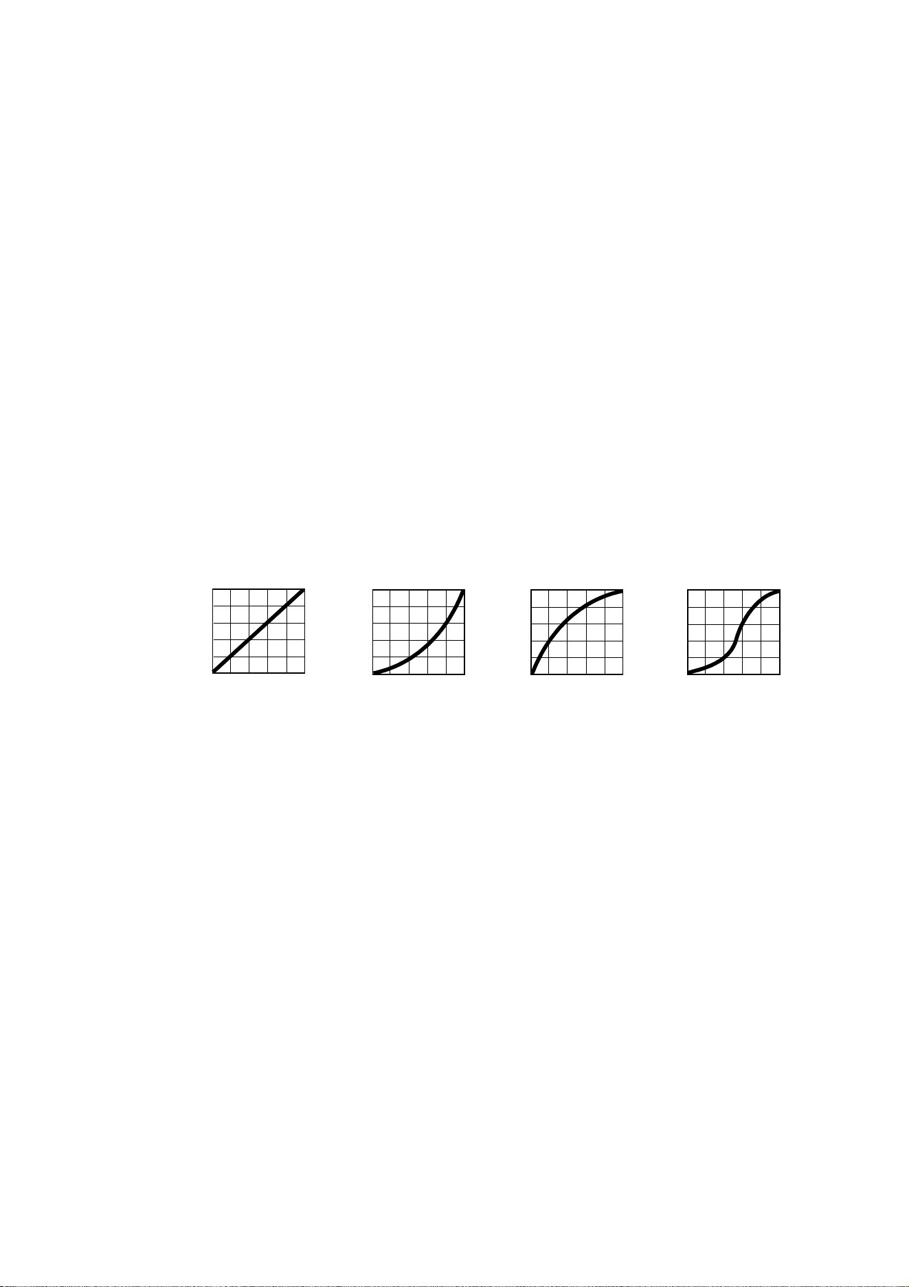
• DIMMER CURVE provides four dimming options (see Figure 6):
- LINEAR – (optically linear) the increase in light intensity appears to be linear as DMX value is
increased.
- SQUARE LAW – light intensity control is finer at low levels and coarser at high levels.
- INV SQUARE LAW – light intensity control is coarser at low levels and finer at high levels.
- S-CURVE – light intensity control is finer at low levels and high levels and coarser at medium levels.
This curve emulates the RMS voltage dimming characteristics of an incandescent lamp.
• TUNGSTEN EMULATOR gives the warm appearance and warm shift dimming characteristics of a
tungsten lamp fixture.
• COLOR MODE provides different modes of CMY flag operation:
- Raw Mode, the default setting, gives direct control of the CMY flags as in all previous software versions.
- Calibrated Mode provides calibration of the CMY flags. Calibrated Mode may be useful if you notice
slight differences in color performance across multiple fixtures. Note that the colors obtained through
CMY color mixing in Calibrated Mode may differ significantly from the colors obtained in Raw Mode.
Multiple fixtures in the same installation should normally ALL be set to either Raw, Calibrated or
Extended Gamut Mode in order to ensure the most consistent color behavior.
- Extended Gamut Mode (available from fixture software version 2.0.0.) gives improved color consistency
across multiple fixtures but is also optimized for color saturation. Calibrated Mode (see above) provides
calibrated colors throughout the entire spectrum at the expense of slightly less saturated deep colors,
but Extended Gamut Mode provides a combination of calibrated mixed colors and saturated deep
colors.
NB: See note under “Service” on page 24 regarding the need for original (or matching) internal modules
inside the fixture when using Calibrated Mode.
• FOCUS TRACKING sets focus to automatically adjust to match the fixture’s zoom angle. You can enable
or disable focus tracking, and you can optimize this feature to give the best performance at far, medium or
near projection distances.
Output
DMX %
DMX %DMX % DMX %
Output
Output
Output
Linear Square law S-curve
Figure 6: Dimming curve options
Inverse square law

Fixture setup
21
• VIDEO TRACKING optimizes performance if the MAC Ultra Performance is used with a video source.
In normal use, the fixture processes the signal it receives, tracking (or smoothing out) changes in values
in order to ensure smooth fading between colors and/or intensities. This signal processing takes fractions
of a second and is normally invisible, but if the fixture is used to display video the processing can interfere
with video response times. If you enable video tracking, the fixture does not ‘smooth out’ input but instead
snaps instantly when a value changes.
If you enable video tracking, some lack of smoothness may be visible when dimming slowly via DMX at
low intensity levels.
When running in P3 Mixed Mode, where the video signal controls both the intensity and color of the
output, you may notice that on very fast video content the CMY flags are unable to follow the fast changes
while intensity is able to follow them. This may lead to white flashes with specific types of content. If you
want to use very fast video content, we recommend that you use P3 Video Mode and control color via
DMX instead of via P3.
For best results, we recommend that you enable video tracking when using video as a source and disable
it (the default setting) during DMX control.
• DMX RESET lets you reduce the risk of accidentally sending a reset command via DMX that might cause
an unwanted blackout and/or unwanted light output in the middle of a show, for example, that will take
several seconds to recover from.
• EFFECT SHORTCUTS determines whether the color and gobo wheels take the shortest path between
two positions (shortcuts enabled), crossing the open position if necessary, or always avoid the open
position (shortcuts disabled).
• COOLING MODE lets you select between five cooling fan options:
- CONSTANT FAN FULL optimizes cooling fan operation for the lowest possible temperature by setting
cooling fans to run constantly at full speed. Light output intensity is reduced if necessary to prevent the
fixture from exceeding its maximum operating temperature during full speed fan operation.
- CONSTANT FAN MEDIUM sets cooling fans to run constantly at medium speed. Light output intensity
is reduced if necessary to prevent the fixture from exceeding its maximum operating temperature during
medium speed fan operation.
- CONSTANT FAN LOW sets cooling fans to run constantly at low speed. Light output intensity is
reduced if necessary to prevent the fixture from exceeding its maximum operating temperature during
low speed fan operation.
- CONSTANT FAN ULOW (ULTRALOW) optimizes cooling fan operation for the lowest possible noise by
setting cooling fans to run constantly at ultra-low speed. Light output intensity is reduced if necessary to
prevent the fixture from exceeding its maximum operating temperature during ultra-low speed fan
operation.
- REGULATED FANS adjusts cooling fan operation to balance the fixture’s noise and light output
characteristics. Cooling fans are set to the lowest speed possible and then increased as fixture
operating temperature rises. If the fixture reaches maximum operating temperature and full-speed fan
operation is not enough to control fixture temperature, light output intensity is limited to keep the fixture
within its operating temperature range.
Because the MAC Ultra Performance adjusts the maximum possible output intensity level as a function of
fixture temperature, the choice of cooling mode will affect the maximum intensity level available. The exact
level will vary depending on factors such as ambient temperature, airflow in the installation etc., but to give
an approximate indication, you can expect to obtain the following intensity levels in the fixture’s different
cooling modes relative to the CONSTANT FAN FULL mode:
- REGULATED FANS: 93%
- CONSTANT FAN ULOW: 72%
- CONSTANT FAN LOW: 96%
- CONSTANT FAN MEDIUM: 99%
- CONSTANT FAN FULL: 100%
• GOBO CT CORRECTION provides an automatic color temperature correction using the CMY flags when
a gobo is inserted into the beam. This counters the typical color temperature shift seen on LED-based
fixtures when inserting a gobo. When this feature is not active, you will see a slight decrease in color
temperature when inserting a gobo, as with other fixtures on the market.
Gobo CT Correction is enabled by default.
• KEYLIGHT CALIBRATION is achieved by adding a small amount of CMY to the spectral enhancement
filter and/or the CTO filter in order to give the most consistent white in multiple fixtures. Values for the

22
MAC Ultra Performance User Guide
amount of cyan, magenta and yellow added are set at the factory, and the calibration data is stored in the
fixture. Replacing either of these filters with a new item may result in a slight shift in color temperature or
spectral enhancement characteristics compared to other fixtures, but the keylight calibration function lets
you recalibrate the fixture and eliminate any inconsistency.
In firmware version 1.5.0, keylight calibration can be toggled between Automatic, Manual and Disabled via
the standard user control menus, the DMX Control and Settings channel, RDM or P3.
- AUTOMATIC uses the keylight calibration values programmed during the original calibration process at
the factory.
- MANUAL uses the custom keylight calibration values programmed on the Control / Settings DMX
channel (see “Adjusting keylight calibration via DMX” on page 26).
- DISABLED disables all factory and custom calibration adjustments for the spectral enhancement filter
and CTO filter – no CMY is added to the output when using one of these filters.
• DISPLAY offers the following options for the LCD display:
- DISPLAY SLEEP sets the fixture display to black out a certain period after the last key press on the
fixture’s control panel. If ERROR MODE (see below) is set to NORMAL, the display will light up again if
the fixtures detects and error.
- DISPLAY INTENSITY lets you adjust the brightness of the display backlighting by setting the intensity
to a level from 10% to 100%.
- DISPLAY ROTATION rotates the display manually through 180° so that it can be read easily no matter
how the fixture is oriented.
- TEMPERATURE UNIT lets you choose whether the fixture should display all temperature readings in
Celsius or Fahrenheit.
• ERROR MODE enables or disables error warnings.
- If set to NORMAL, the display is activated and lights up if the fixture needs to report an error.
- If set to SILENT, the fixture does not light the display with error warnings but error messages can still be
read when the display is activated manually.
In both NORMAL and SILENT modes, the status LED lights amber to indicate a warning and red to
indicate an error.
• HIBERNATION MODE sets light output intensity to zero and disables effect deployment and pan/tilt
movement. The main purpose of the mode is to protect the fixture from the intake of airborne material
such as dust and confetti and to provide an option for situations where noise is critical. The small
reduction in power consumption obtained in Hibernation Mode is not the main purpose of this mode.
When you bring the fixture out of hibernation mode, it performs a full reset.
• FRAMING MODE is available from firmware v. 2.2.x. It offers two options for the way that the framing
blades are managed to ensure that each blade does not contact or affect any other blade:
- LEGACY framing mode emulates a 2-layer framing system, like the one found in Martin's MAC Viper
and MAC Encore fixtures. This mode limits framing blades to maximum 50% deployment at maximum
DMX value. The corners of angled blades are also limited to maximum 50% deployment.
- STANDARD framing mode uses an algorithm which designates primary and secondary framing blades.
Secondary blades must always make room for primary blades. Priority is given to angled blades.
• SCENE CAPTURE lets you capture all the DMX values that the fixture is currently receiving and save
them as a scene. If you enable PLAYBACK, the fixture will show that scene every time it is powered on or
you carry out a reset.
- If the fixture receives a DMX control signal during playback, it will immediately stop showing its saved
scene. If the fixture is powered off and on again or if the fixture is reset, it will again show its saved
scene.
- To stop the fixture showing its saved scene at each power cycle or reset, set
PLAYBACK to DISABLE
in the SCENE CAPTURE menu or on the DMX Control / Settings channel.
Managing fixture settings
Factory default settings
FACTORY DEFAULT lets you reload the fixture’s factory default settings. Effect calibration settings are not
affected, so any changes you have made to zoom, pan and tilt offsets will be kept.

Fixture setup
23
Custom settings
The custom configuration function CUSTOM 1 - CUSTOM 3 allows you to save and recall up to three sets of
fixture settings. These include all the settings in the PERSONALITY menu as well as the fixture’s DMX
address.
Fixture information readouts
The following fixture information can be called up in the display:
• POWER ON TIME provides two counters, one user-resettable, one non-resettable, that display the total
number of hours the fixture has been powered on since manufacture.
• POWER ON CYCLES provides two counters, one user-resettable, one non-resettable, that display the
total number of power on/off cycles since manufacture.
• SW VERSION displays the currently installed firmware (fixture software) version.
• RDM UID displays the fixture’s factory-set unique ID for identification in RDM systems.
• FAN SPEEDS provides separate status readouts from the fixture’s cooling fans.
Temperatures
The TEMPERATURES menu provides separate temperature readouts for each of the fixture’s PCBs. You
can choose to see the current readout or the minimum and maximum temperature levels since the fixture
was last powered on.
DMX signal monitoring
The MAC Ultra Performance provides data on the DMX signal it is receiving in the DMX LIVE menu. This
information can be useful for troubleshooting control problems.
• RATE displays the DMX refresh rate in packets per second. Values lower than 10 or higher than 44 may
result in erratic performance, especially when using tracking control.
• QUALITY displays the quality of the received DMX data as a percentage of usable packets from the data
received. Values much below 100 indicate interference, poor connections, or other problems with the
serial data link that are the most common cause of control problems.
• START CODE displays the DMX start code. Packets with a start code other than 0 may cause irregular
performance.
The DMX LIVE menu lets you scroll through all the fixture’s DMX channels and display the DMX values from
0 - 255 that are being received on each channel.
Test sequences
The FIXTURE TEST menu lets you test:
• all the fixture’s effects
• dimming functionality
• each individual mechanical effect, or
• pan and tilt only.
Before you run a test, prepare for the head to move and the fixture to light up suddenly without warning.
To run a test:
• In the FIXTURE TEST menu, scroll to TEST ALL, TEST LEDS, TEST EFFECTS or TEST PAN/TILT and
press ENTER.
• In the TEST EFFECTS menu, scroll to the effect you want to test and press ENTER to start a test
sequence for that effect.
• In the TEST PAN/TILT menu, choose PAN or TILT, make sure that the fixture base is held securely and
that there is no danger of the fixture falling over or head colliding, then press ENTER to start the test
sequence.
• Press MENU to stop the test sequence.

24
MAC Ultra Performance User Guide
Manual control
The MANUAL CONTROL menu lets you reset the fixture and operate it without a DMX controller.
To execute commands in the MANUAL CONTROL menu, select the effect that you want to control, then
enter a value from 0 to 255 for 8-bit commands or 0 to 65536 for 16-bit commands to apply that command.
The menu items and values available correspond to the commands listed in the DMX protocol in this User
Manual.
When you exit the MANUAL CONTROL menu, the fixture will keep its effect positions and settings until you
enter a new menu. When you do this, the fixture will revert to default positions and settings. The fixture will
also revert to default positions and settings if you exit and then re-enter MANUAL CONTROL.
Service
Servicing the fixture and the contents of the SERVICE menu are also covered in the MAC Ultra
Performance Safety and Installation Manual supplied with fixtures and available for download from the
product pages on the Martin website at www.martin.com.
Pan/tilt auto-calibration
From firmware v. 2.0.0, you can auto-calibrate pan and tilt in the SERVICE → ADJUST menu.
Important! Pan and tilt move through their full movement range during auto-calibration. Make sure that the
fixture is secure and that there is space around the head for full pan and tilt movement before you carry out
this function.
Module and fixture calibration
Fixtures are calibrated at the factory when the light engine, CMY module and effect module (color wheel
effects module) are installed. We therefore recommend that you keep the original modules with the fixture if
you disassemble the fixture for service. If you swap modules from one fixture to another, the fixtures may
need to be recalibrated in order to maintain consistent color characteristics across different fixtures. A small
label indicating the type and serial number of the original fixture is fixed to each module at the factory to help
you keep modules together with their original fixture.
If you have replaced a module or a CMY flag and you notice a difference in color output compared with other
MAC Ultra Performance fixtures, firmware v. 2.0.0 and later lets you choose from various options for
deciding which source of calibration data the fixture will use in the SERVICE
→ COLOR CAL DATA menu.
You can set the fixture to select a source of calibration data automatically, use the data stored on the main
board or light engine board, or you can choose from one of five pre-programmed calibration data settings,
using the setting that gives the best color match across fixtures.
Calibrated Mode requires original internal modules
For the Calibrated Color Mode to function properly when running (and when uploading) firmware version
1.6.0 or later, the original main board, the original light engine and the original CMY module must be
installed together in the same fixture. If there is a possibility that one or more of these modules has been
replaced, we recommend that a qualified service technician with service documentation from Martin
Professional opens the fixture to check. There is no specific serial number label on the main board module
(UI PCBA), but the light engine module and CMY module are labeled with serial numbers that should be
identical with the serial number located on the bottom of the fixture base if they are the original modules.

Adjusting settings via DMX
25
Adjusting settings via DMX
Certain fixture settings and parameters can be adjusted from the DMX controller on Channel 42, the Fixture
Control/Settings channel. Commands sent on this channel override any settings entered in the fixture’s
onboard control menus.
To help you avoid accidentally applying a setting that may disrupt a light show, for example, the commands
must be held for a certain time before they are applied. For example, the command that turns off the display
illumination must be held for one second to activate it. The command that resets the fixture must be held for
five seconds to activate it. The DMX protocol table in this user manual gives details of times required.
Resetting
Either the entire fixture or individual effects can be reset to their initial positions. Resetting individual effects
can allow on-the-fly recovery if an effect loses its correct position, for example, without having to reset the
entire fixture.
Illuminating the display
You can set the fixture’s display panel to ON or OFF with a DMX command. This makes it possible to read
the fixture’s DMX address while the fixture is installed in the rig but black out the display panel during a
show.
If the display is set to ON via DMX, it will enter sleep mode and black out after a short period of inactivity. To
bring it out of sleep mode, set the display to ON again via DMX.
Control menu setting overrides
The following fixture settings can be adjusted via DMX, overriding the settings entered in the onboard
control menus. See under “DMX protocol” on page 27 for details of these settings.
• Dimming curve
• Tungsten emulation
• Pan and tilt speed
• Effect shortcuts, also called parameter shortcuts (effects take shortest route when changing, even if this
means crossing the open position)
• Focus tracking
• Video tracking
• Fan speed
It is also possible to adjust calibration offsets via DMX. This feature can be useful if you want to fine-tune
pan, tilt or other effects after fixtures have been installed in a lighting rig, for example.
Adjusting calibration offsets via DMX
You can adjust the home positions of pan, tilt and all the fixture’s effects remotely via DMX by setting custom
calibration offsets on the Control/Settings DMX channel.
To set a custom offset in the position of an effect:
1. Set the effect to a specific value via DMX (for example, set all the fixtures in a group to DMX value 200
on the zoom channel).
2. Select ‘Enable calibration adjustment’ on the Control/Settings channel and hold for 5 seconds to
activate.
3. The fixture now registers the current positions of all effects and holds them there. To select an effect to
adjust, you must first release it from its hold position by changing the value on its DMX channel by
+/- 10%. The effect then returns to its hold position. The effect's DMX channel now represents the full

26
MAC Ultra Performance User Guide
calibration range. The range can vary but is typically +/- 5-10%. In this case you can adjust the effect’s
position using that effect’s DMX channel (8 or 16 bit) as follows:
• DMX value 0 = -5%
• DMX value 127/32767 = 0%
• DMX value 255/65535 = +5%.
4. Adjust the effect until it is in the required position (for example, adjust the zoom angle on each fixture in
the group until the angle on all fixtures is identical – this is the position that you will obtain when you
send DMX value 200).
5. Send a ‘Store XXX calibration’ command on the Control/Settings channel for each effect that you adjust
and hold that command for 5 seconds to activate. The new calibration offset is now stored in memory.
6. When you have finished adjusting calibration offsets, send value 0 on the Control/Settings channel and
hold for 5 seconds to exit the DMX calibration procedure and return to normal DMX control.
Calibration offsets that are stored in memory are not affected by powering the fixture off and on or by
updating the fixture software.
Restoring default calibration offsets
If you want to delete all custom calibration offsets and return the offsets to their default values:
1. On the Control/Settings DMX channel, send a ‘Return all calibration settings to factory defaults’
command and hold for 5 seconds.
2. The fixture will return all effects to their default calibration values.
Note that, If you have overwritten the factory default values by applying a SERVICE → CALIBRATION →
SAVE DEFAULTS command in the fixture’s onboard control panel, the fixture will return to the calibration
values that were saved as the default values at that time. The SAVE DEFAULTS command in the fixture’s
control panel permanently replaces the factory default calibration settings with the current custom
calibration settings.
Adjusting keylight calibration via DMX
Recalibration may become necessary to keep the keylight characteristics of multiple fixtures consistent if
you replace the color temperature or spectral enhancement filter with a new one. See also the point
KEYLIGHT SETTINGS on page 21.
Adjusting keylight calibration involves setting the amount of Cyan, Magenta and Yellow that is added to the
CTO or spectral enhancement filter in order to fine-tune the output characteristics across multiple fixtures.
You carry out these adjustments remotely via DMX.
To adjust the keylight calibration settings in multiple fixtures:
1. Apply power to the fixtures that you want to calibrate and aim them at an even white surface.
2. On each fixture, go to the Control / Settings DMX channel (Ch. 42), and hold the DMX value required for
Start CTO keylight calibration or Start spectral enhancement keylight calibration for 5 seconds.
The fixture will engage the CTO or spectral enhancement filter and set CMY to 0%.
3. On each fixture’s CMY channels, adjust the CMY values until the output of all fixtures looks the same.
4. On the Control / Settings channel, hold the DMX value required for Store CTO keylight calibration or
Store spectral enhancement keylight calibration for 5 seconds.
The fixture will now behave as follows:
• When keylight calibration is used in MANUAL mode, it will use the custom values stored using the above
procedure.
• When keylight calibration is used in AUTOMATIC mode, it will use the values stored during the original
calibration procedure at the factory.
DMX protocol
27
DMX protocol
Basic Mode
MAC Ultra Performance firmware version 2.3.x
Channel DMX Value Function
Fade
type
Default
value
Strobe / Intensity
1
0 - 19
20 - 49
50 - 200
201 - 210
211 - 255
Strobe/shutter effect
Shutter closed
Shutter open
Strobe, slow → fast
Shutter open
Random strobe, slow → fast
Snap 30
2
0 - 65535
Dimmer (16-bit)
Closed → open
Fade 0
3
Color
4
0 - 65535
Cyan (16-bit)
0 → 100%
Fade 0
5
6
0 - 65535
Magenta (16-bit)
0 → 100%
Fade 0
7
8
0 - 65535
Yellow (16-bit)
0 → 100%
Fade 0
9
10
0 - 65535
CTC (16-bit)
0 → 100%
Fade 0
11
12
0
1 - 14
15
16 - 29
30
31 - 44
45
46 - 59
60
61 - 74
75
76 - 89
90
91 - 104
105 - 160
161 - 163
164 - 166
167 - 169
170 - 172
173 - 175
176 - 178
179 - 192
193 - 214
215 - 221
222 - 243
244 - 247
248 - 251
252 - 255
Color wheel
Indexing
Split colors (continuous color wheel indexing)
Open
Open → Color 1
Color 1 (Spectral enhancement)
Color 1 → Color 2
Color 2 (Blue)
Color 2 → Color 3
Color 3 (Deep Green)
Color 3 → Color 4
Color 4 (Orange)
Color 4 → Color 5
Color 5 (Navy Blue)
Color 5 → Color 6
Color 6 (Deep Red)
Color 6 → Open
Open
Solid colors
Color 1 (Spectral enhancement)
Color 2 (Blue)
Color 3 (Deep Green)
Color 4 (Orange)
Color 5 (Navy Blue)
Color 6 (Deep Red)
Open
Continuous rotation
CW, fast → slow
Stop (wheel stops at current position)
CCW slow → fast
Random colors
Fast
Medium
Slow
Snap 0
Table 2: MAC Ultra Performance Basic Mode DMX Protocol

28
MAC Ultra Performance User Guide
Gobos
13
0 - 9
10 - 14
15 - 19
20 - 24
25 - 29
30 - 34
35 - 39
40 - 44
45 - 49
50 - 54
55 - 59
60 - 89
90 - 119
120 - 149
150 - 179
180 - 209
210 - 232
233 - 255
Gobo wheel 1 selection
Gobo indexing (set angle on channels 14 and 15)
Open
Gobo 1 (Time Ripples)
Gobo 2 (Look Sharper)
Gobo 3 (Compass)
Gobo 4 (Deep Space)
Gobo 5 (Radar)
Gobo rotation (set direction and speed on channels 14 and 15)
Gobo 1
Gobo 2
Gobo 3
Gobo 4
Gobo 5
Gobo shake (set center angle on channels 14 and 15)
Gobo 1 shake slow 360° → fast 10°
Gobo 2 shake slow 360° → fast 10°
Gobo 3 shake slow 360° → fast 10°
Gobo 4 shake slow 360° → fast 10°
Gobo 5 shake slow 360° → fast 10°
Gobo wheel rotation, indexed gobos (set gobo indexed angle on
channels 14 and 15)
Gobo wheel rotation CW fast → slow
Gobo wheel rotation CCW slow → fast
Snap 0
14
0- 65535
0 - 600
601 - 32130
32131 - 32895
32896 - 64515
64516 - 65535
Gobo wheel 1 indexed position/rotation (16-bit)
Gobo indexing
Indexed angle, 0° at 32768
Gobo rotation
Stop, gobo indexed at 0°
Gobo rotation CW fast → slow
Stop, gobo stops at current position
Gobo rotation CCW slow → fast
Stop, gobo indexed at 90°
Fade 32768
15
16
0 - 9
10 - 14
15 - 19
20 - 24
25 - 29
30 - 34
35 - 39
40 - 44
45 - 49
50 - 54
55 - 59
60 - 89
90 - 119
120 - 149
150 - 179
180 - 209
210 - 232
233 - 255
Gobo wheel 2 selection
Gobo indexing (set angle on channels 17 and 18)
Open
Gobo 1 (String Theory)
Gobo 2 (Hazey Waves)
Gobo 3 (Limbo)
Gobo 4 (Up Is Down)
Gobo 5 (Brush Up)
Gobo rotation (set direction and speed on channels 17 and 18)
Gobo 1
Gobo 2
Gobo 3
Gobo 4
Gobo 5
Gobo shake (set center angle on channels 17 and 18)
Gobo 1 shake slow 360° → fast 10°
Gobo 2 shake slow 360° → fast 10°
Gobo 3 shake slow 360° → fast 10°
Gobo 4 shake slow 360° → fast 10°
Gobo 5 shake slow 360° → fast 10°
Gobo wheel rotation, indexed gobos (set gobo indexed angle on
channels 17 and 18)
Gobo wheel rotation CW fast → slow
Gobo wheel rotation CCW slow → fast
Snap 0
17
0- 65535
0 - 600
601 - 32130
32131 - 32895
32896 - 64515
64516 - 65535
Gobo wheel 2 indexed position/rotation (16-bit)
Gobo indexing
Indexed angle, 0° at 32768
Gobo rotation
Stop, gobo indexed at 0°
Gobo rotation CW fast → slow
Stop, gobo stops at current position
Gobo rotation CCW slow → fast
Stop, gobo indexed at 90°
Fade 32768
18
Channel DMX Value Function
Fade
type
Default
value
Table 2: MAC Ultra Performance Basic Mode DMX Protocol
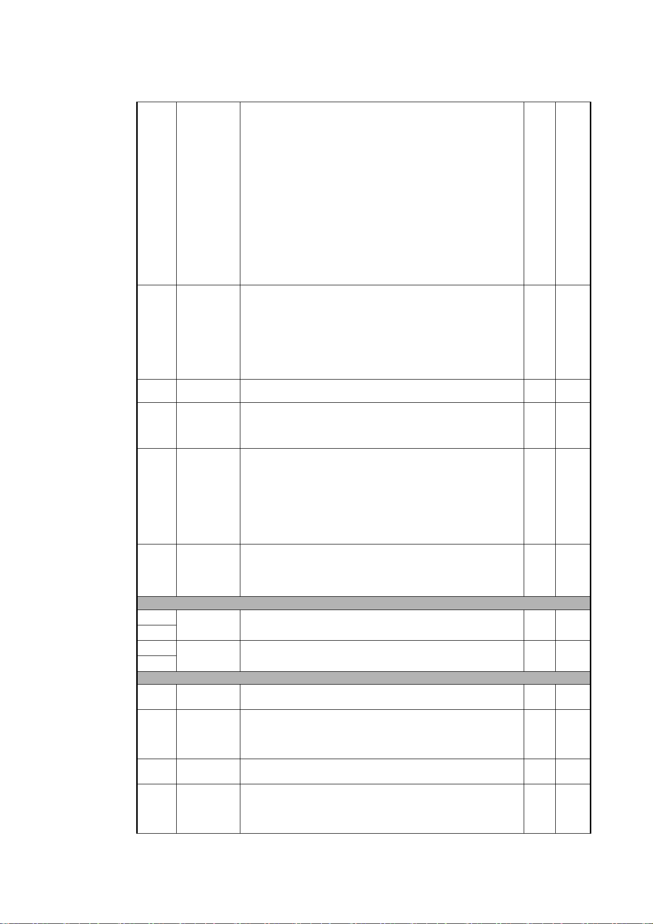
DMX protocol
29
19
0 - 5
6 - 10
11 - 15
16 - 20
21 - 25
26
27 - 59
60
61 - 109
110
111
112 - 198
199
200 - 254
255
Animation wheel indexing /rotation
Open
Horizontal position indexed
Horizontal position rotation
Vertical position rotation
Vertical position indexed
Angled rotation (set direction and speed on Channel 20)
Angled rotation - Wheel outside gate
Angled rotation - Wheel moving into gate
Angled rotation - Wheel in horizontal position
Angled rotation - Wheel in angled position
Angled rotation - Wheel in vertical position
Angled indexing (set indexing angle on Channel 20)
Angled indexing - Wheel in vertical position
Angled indexing - Wheel in angled position
Angled indexing - Wheel in horizontal position
Angled indexing - Wheel moving out of gate
Angled indexing - Wheel outside gate
Snap 0
20
0 - 255
0 - 2
3 - 126
127 - 129
130 - 253
254 - 255
Animation wheel indexed position/rotation speed
Indexed position
Position, min. → max.
Rotation speed and direction
Stop, indexed at 0°
Continuous rotation CW fast → slow
Stop, wheel stops at current position
Continuous rotation CCW slow → fast
Stop, indexed at 90°
Fade 128
21
0 - 255
Frost
No frost → full frost
Fade 0
22
0 - 10
11 - 138
139 - 255
Prism indexing/rotation
Open
Indexed position
Rotation
Snap 0
23
0 - 255
0 - 2
3 - 126
127 - 129
130 - 253
254 - 255
Prism indexed position/rotation speed
Indexed position
Position, min. → max. (128 = index 0°)
Rotation speed and direction
Stop, indexed at 0°
Continuous rotation CW fast → slow
Stop, prism stops at current position
Continuous rotation CCW slow → fast
Stop, indexed at 45°
Fade 128
24
0 - 200
201 - 225
226 - 230
231 - 255
Iris
Open → closed
Animate fast → slow
Iris stops at current position
Animate reverse slow → fast
Fade 0
Zoom / Focus
25
0 - 65535
Zoom (16-bit)
Wide → narrow
Fade 32768
26
27
0 - 65535
Focus (16-bit)
Infinity → near
Fade 32768
28
Framing
29
0 - 255
Framing blade 1 (top): position
Out → in
Fade 0
30
0 -126
127 - 128
129 - 255
Framing blade 1: angle
Angle –
Parallel
Angle +
Fade 128
31
0 - 255
Framing blade 2 (right-hand): position
Out → in
Fade 0
32
0 -126
127 - 128
129 - 255
Framing blade 2: angle
Angle –
Parallel
Angle +
Fade 128
Channel DMX Value Function
Fade
type
Default
value
Table 2: MAC Ultra Performance Basic Mode DMX Protocol
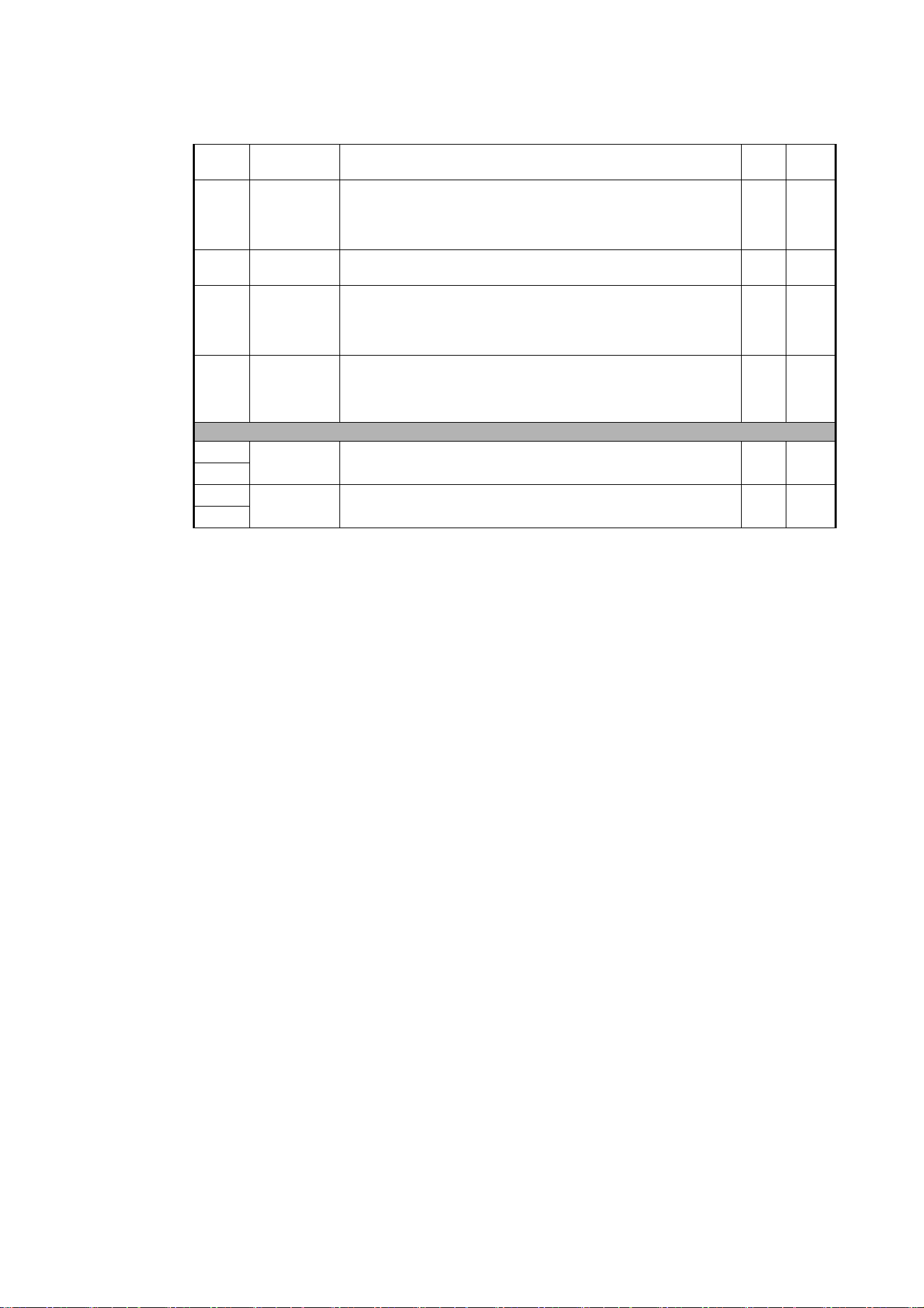
30
MAC Ultra Performance User Guide
33
0 - 255
Framing blade 3 (bottom): position
Out → in
Fade 0
34
0 -126
127 - 128
129 - 255
Framing blade 3: angle
Angle –
Parallel
Angle +
Fade 128
35
0 - 255
Framing blade 4 (left-hand): position
Out → in
Fade 0
36
0 -126
127 - 128
129 - 255
Framing blade 4: angle
Angle –
Parallel
Angle +
Fade 128
37
0 -126
127 - 128
129 - 255
Framing module angle
Angle –
Parallel
Angle +
Fade 128
Movement
38
0 - 65535
Pan (16-bit)
Left → right
Fade 32768
39
40
0 - 65535
Tilt (16-bit)
Forward → backward
Fade 32768
41
Channel DMX Value Function
Fade
type
Default
value
Table 2: MAC Ultra Performance Basic Mode DMX Protocol

DMX protocol
31
Control / Settings
42
0 - 9
10 - 14
15
16
17
18
19 - 22
23
24
25
26
27
28
29
30
31
32
33
34
35
36
37
38
39
40
41- 51
52
53
54
55
56
57
58
59 - 60
Fixture control/settings
(hold for number of seconds indicated to activate)
Exit calibration adjustment and return to normal control – 5 sec.
Reset entire fixture – 5 sec.
No function
Reset color – 5 sec.
Reset beam only – 5 sec.
Reset pan and tilt only – 5 sec.
No function
Linear dimming curve – 1 sec.
(menu override, setting unaffected by power off/on)
Square law dimming curve – 1 sec.
(menu override, default setting, setting unaffected by power off/on)
Inverse square law dimming curve – 1 sec.
(menu override, setting unaffected by power off/on)
S-curve dimming curve – 1 sec.
(menu override, setting unaffected by power off/on)
Standard pan and tilt speed – 1 sec. (default setting)
Fast pan and tilt – 1 sec.
(menu override - setting returns to Standard pan and tilt speed after
power on/off)
Smooth pan and tilt – 1 sec.
(menu override - setting returns to Standard pan and tilt speed after
power on/off)
Effect shortcuts on (default setting)
Effect shortcuts off
Disable focus tracking – 1 sec.
Focus tracking = Near distance – 1 sec.
Focus tracking = Medium distance (default setting) – 1 sec.
Focus tracking = Far distance – 1 sec.
Enable video tracking
Disable video tracking (default setting)
Extended gamut mode – 1 sec.
Calibrated color mode – 1 sec.
Raw color mode (default setting) – 1 sec.
No function
Control panel display on (default setting) – 1 sec.
Control panel display off – 1 sec.
Regulated fan speed, fixed light output intensity (default setting) – 1 sec.
Full fan speed, regulated light output intensity – 1 sec.
Medium fan speed, regulated light output intensity – 1 sec.
Low fan speed, regulated light output intensity – 1 sec.
Ultra-low fan speed, regulated light output intensity – 1 sec.
No function
Snap 0
Channel DMX Value Function
Fade
type
Default
value
Table 2: MAC Ultra Performance Basic Mode DMX Protocol

32
MAC Ultra Performance User Guide
42
contd.
61
62
63
64
65
66
67
68
69
70
71
72
73
74
75
76
77 - 78
79
80
81 - 86
87
88
89
90 - 93
94
95
96 - 99
100
101
102
103
104
105
106
107
108
109
110
111
112
113
114
115
116 - 193
194
195
196
197
198
199
200 - 255
Hibernation mode on – 1 sec.
Hibernation mode off – 1 sec.
Followspot mode on – 5 sec.
Followspot mode off (default setting) – 5 sec.
Pan and tilt limits on – 1 sec.
Pan and tilt limits off (default setting) – 1 sec.
Pan limit low – 1 sec.
Pan limit high – 1 sec.
Tilt limit low – 1 sec.
Tilt limit high – 1 sec.
Reset pan and tilt limits – 1 sec.
Tungsten emulation on – 1 sec.
Tungsten emulation off (default setting) – 1 sec.
Scene capture record – 5 sec.
Scene capture playback on – 5 sec.
Scene capture playback off (default setting) – 5 sec.
No function
Gobo CT correction on (default setting) – 1 sec.
Gobo CT correction off – 1 sec.
No function
Keylight calibration disabled – 1 sec.
Keylight calibration manual – 1 sec.
Keylight calibration automatic (default setting) – 1 sec.
No function
Framing mode = Standard – 1 sec.
Framing mode = Legacy – 1 sec.
No function
Enable calibration adjustment – 5 sec.
Store pan and tilt calibration – 5 sec.
Store dimmer calibration – 5 sec.
Store Cyan calibration – 5 sec.
Store Magenta calibration – 5 sec.
Store Yellow calibration – 5 sec.
Store CTC calibration – 5 sec.
Store all CMYC calibration – 5 sec.
Store rotating gobo wheel 1 calibration – 5 sec.
Store rotating gobo wheel 2 calibration – 5 sec.
Store animation wheel calibration – 5 sec.
Store framing system calibration – 5 sec.
Store iris calibration – 5 sec.
Store focus calibration – 5 sec.
Store zoom calibration – 5 sec.
Store color wheel calibration – 5 sec.
No function
Start CTO keylight calibration – 5 sec.
Start spectral enhancement keylight calibration – 5 sec.
Store CTO keylight enhancement keylight calibration – 5 sec.
Store spectral enhancement keylight calibration – 5 sec.
Store all calibration settings (except keylight settings) – 5 sec.
Return all calibration settings (except keylight settings) to factory
defaults – 5 sec.
No function
Snap 0
Channel DMX Value Function
Fade
type
Default
value
Table 2: MAC Ultra Performance Basic Mode DMX Protocol
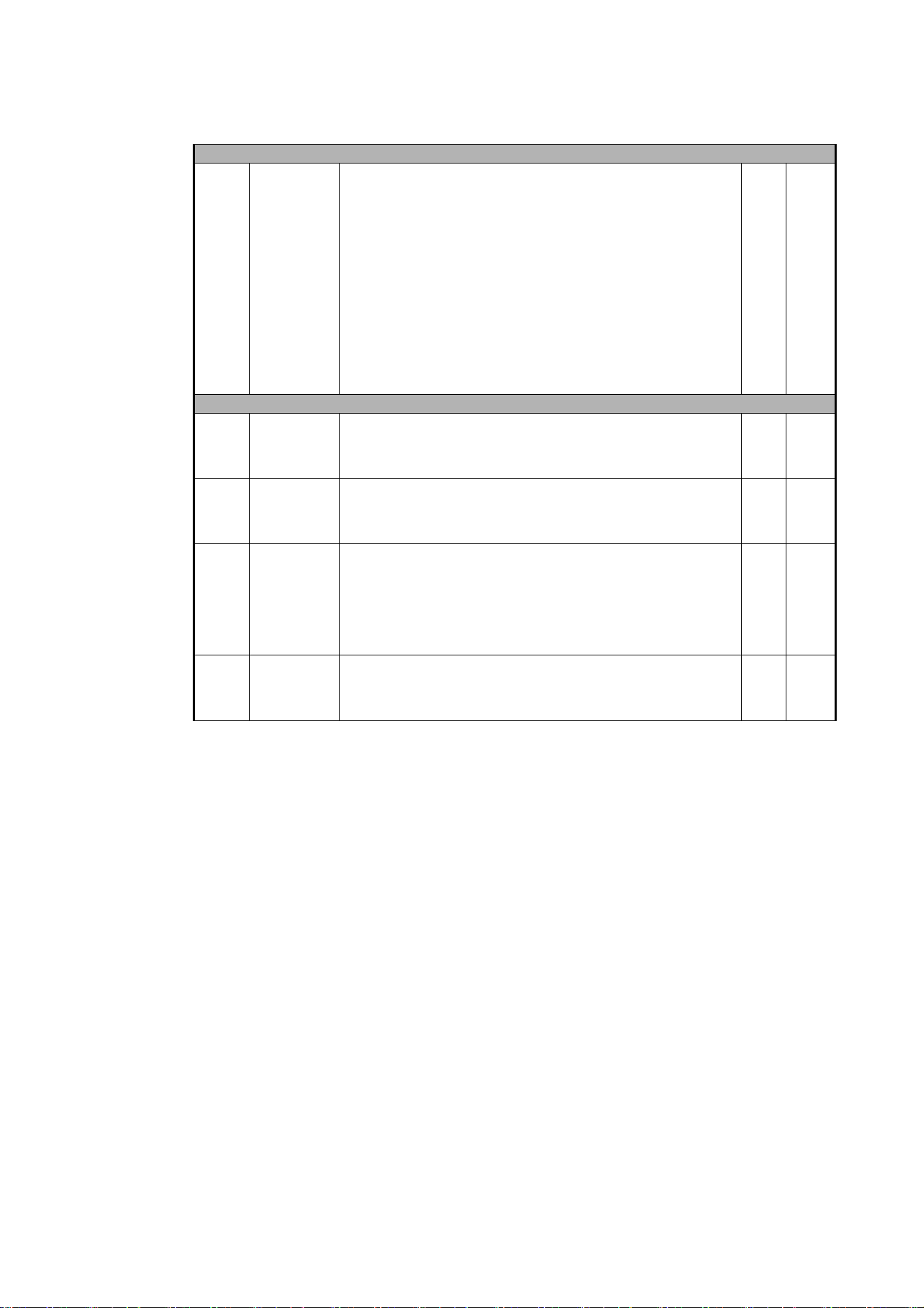
DMX protocol
33
P3 Mix
43
0 - 26
27 - 228
229 - 255
P3 Mix
DMX Mode
Intensity and colors fully controlled by DMX, P3 pixel data ignored
Mixed Mode
Cross-fade from DMX control of intensity and colors to P3 control of
intensity and colors:
• At 27, intensity and colors are still fully controlled by DMX.
• Between 27 and 228, you mix/crossfade from DMX to P3 control.
• At 228, the Intensity of each of the 10 x Animotion segments is
controlled by 10 x separate P3 pixels and color is controlled by P3
Pixel 1 (the black pixel on the P3 map).
Video Mode
Intensity of 10 x Animotion segments controlled by P3, color controlled
by DMX (DMX channels ‘color’ the P3 pixel data)
Snap 0
Pre-programmed FX
44
0
1 - 254
255
FX1 selection (see FX table on page 44)
No effect
Effect selection (adjust speed and direction on channel 45)
Enable PWM frequency adjustment (adjust frequency on channel 45)
Snap 0
45
0 - 126
127 - 129
130 - 255
FX1 speed and direction
Effect reversed fast → slow
Effect stops
Effect forward slow → fast
Fade 128
46
0
1 - 159
160
161 - 194
195 - 254
255
FX2 selection (see FX table on page 44)
No effect
Effect selection (adjust speed and direction on channel 47)
Enable FX1 y-axis control on channel 47
No function (these FX are available for FX1 only)
Effect selection (adjust speed and direction on channel 47)
Enable PWM frequency adjustment (adjust frequency on channel 47)
Snap 0
47
0 - 126
127 - 129
130 - 255
FX2 speed and direction
Effect reversed fast → slow
Effect stops
Effect forward slow → fast
Fade 128
Channel DMX Value Function
Fade
type
Default
value
Table 2: MAC Ultra Performance Basic Mode DMX Protocol

34
MAC Ultra Performance User Guide
Compact Mode
This mode is available from MAC Ultra Performance firmware version 2.3.x
Compact Mode is identical to Basic Mode, but the P3 Mix and FX channels are removed to give a DMX
footprint of 42 channels.
48
0
1
2
3
4
5
6
7
8
9
10
11
12
13
14
15
16
17
18
19
20
21
22
23
24
25
26
27
28
29
30
31
32
33
34
35
36
37 - 100
101 - 120
121 - 140
141 - 255
FX synchronization
No sync
Offset shift 10°
Offset shift 20°
Offset shift 30°
Offset shift 40°
Offset shift 50°
Offset shift 60°
Offset shift 70°
Offset shift 80°
Offset shift 90°
Offset shift 100°
Offset shift 110°
Offset shift 120°
Offset shift 130°
Offset shift 140°
Offset shift 150°
Offset shift 160°
Offset shift 170°
Offset shift 180°
Offset shift 190°
Offset shift 200°
Offset shift 210°
Offset shift 220°
Offset shift 230°
Offset shift 240°
Offset shift 250°
Offset shift 260°
Offset shift 270°
Offset shift 280°
Offset shift 290°
Offset shift 300°
Offset shift 310°
Offset shift 320°
Offset shift 330°
Offset shift 340°
Offset shift 350°
Synchronized: all fixtures start FX cycles at same time
No function
Random start (Channel 45 controls overall speed)
Random duration
No function
Snap 36
Channel DMX Value Function
Fade
type
Default
value
Table 2: MAC Ultra Performance Basic Mode DMX Protocol
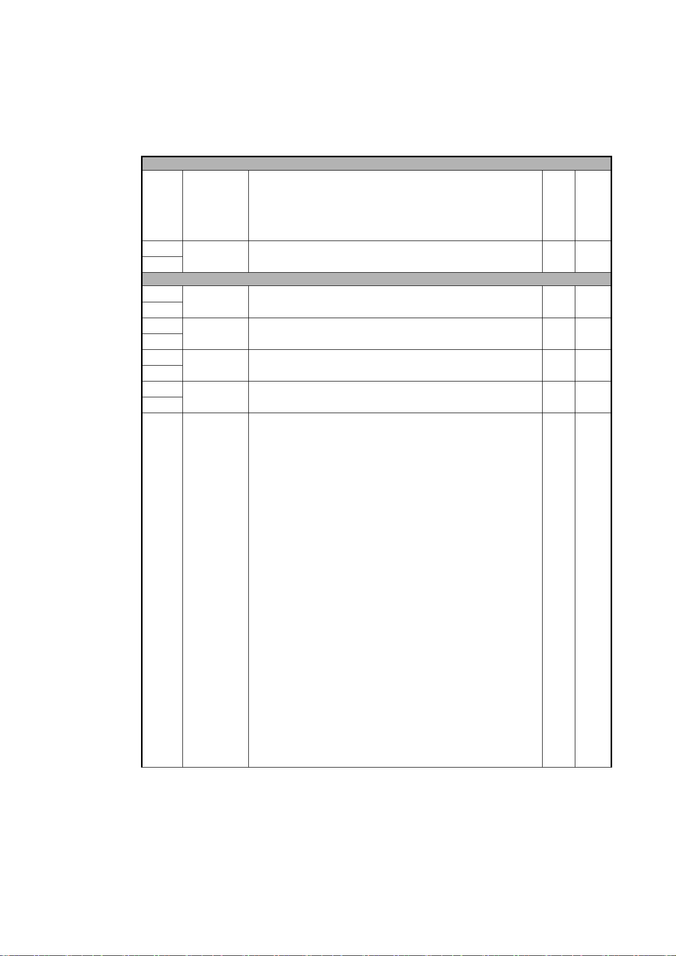
DMX protocol
35
Extended Mode
MAC Ultra Performance firmware version 2.3.x.
Channel DMX Value Function
Fade
type
Default
value
Strobe / Intensity
1
0 - 19
20 - 49
50 - 200
201 - 210
211 - 255
Strobe/shutter effect
Shutter closed
Shutter open
Strobe, slow → fast
Shutter open
Random strobe, slow → fast
Snap 30
2
0 - 65535
Dimmer (16-bit)
Closed → open
Fade 0
3
Color
4
0 - 65535
Cyan (16-bit)
0 → 100%
Fade 0
5
6
0 - 65535
Magenta (16-bit)
0 → 100%
Fade 0
7
8
0 - 65535
Yellow (16-bit)
0 → 100%
Fade 0
9
10
0 - 65535
CTC (16-bit)
0 → 100%
Fade 0
11
12
0
1 - 14
15
16 - 29
30
31 - 44
45
46 - 59
60
61 - 74
75
76 - 89
90
91 - 104
105 - 160
161 - 163
164 - 166
167 - 169
170 - 172
173 - 175
176 - 178
179 - 192
193 - 214
215 - 221
222 - 243
244 - 247
248 - 251
252 - 255
Color wheel
Indexing
Split colors (continuous color wheel indexing)
Open
Open → Color 1
Color 1 (Spectral enhancement)
Color 1 → Color 2
Color 2 (Blue)
Color 2 → Color 3
Color 3 (Deep Green)
Color 3 → Color 4
Color 4 (Orange)
Color 4 → Color 5
Color 5 (Navy Blue)
Color 5 → Color 6
Color 6 (Deep Red)
Color 6 → Open
Open
Solid colors
Color 1 (Spectral enhancement)
Color 2 (Blue)
Color 3 (Deep Green)
Color 4 (Orange)
Color 5 (Navy Blue)
Color 6 (Deep Red)
Open
Continuous rotation
CW, fast → slow
Stop (wheel stops at current position)
CCW slow → fast
Random colors
Fast
Medium
Slow
Snap 0
Table 3: MAC Ultra Performance Extended Mode DMX Protocol
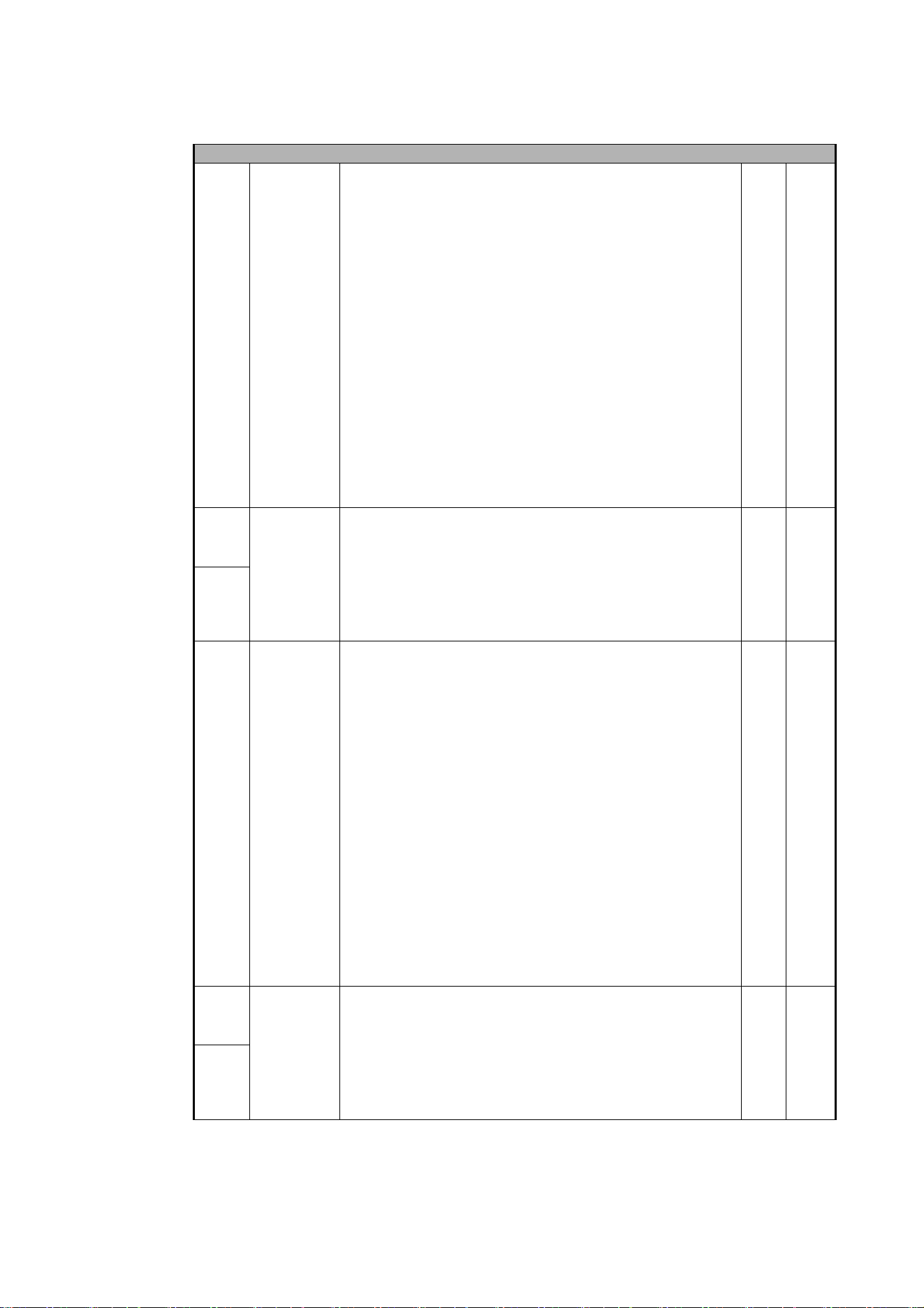
36
MAC Ultra Performance User Guide
Gobos
13
0 - 9
10 - 14
15 - 19
20 - 24
25 - 29
30 - 34
35 - 39
40 - 44
45 - 49
50 - 54
55 - 59
60 - 89
90 - 119
120 - 149
150 - 179
180 - 209
210 - 232
233 - 255
Gobo wheel 1 selection
Gobo indexing (set angle on channels 14 and 15)
Open
Gobo 1 (Time Ripples)
Gobo 2 (Look Sharper)
Gobo 3 (Compass)
Gobo 4 (Deep Space)
Gobo 5 (Radar)
Gobo rotation (set direction and speed on channels 14 and 15)
Gobo 1
Gobo 2
Gobo 3
Gobo 4
Gobo 5
Gobo shake (set center angle on channels 14 and 15)
Gobo 1 shake slow 360° → fast 10°
Gobo 2 shake slow 360° → fast 10°
Gobo 3 shake slow 360° → fast 10°
Gobo 4 shake slow 360° → fast 10°
Gobo 5 shake slow 360° → fast 10°
Gobo wheel rotation, indexed gobos (set gobo indexed angle on
channels 14 and 15)
Gobo wheel rotation CW fast → slow
Gobo wheel rotation CCW slow → fast
Snap 0
14
0- 65535
0 - 600
601 - 32130
32131 - 32895
32896 - 64515
64516 - 65535
Gobo wheel 1 indexed position/rotation (16-bit)
Gobo indexing
Indexed angle, 0° at 32768
Gobo rotation
Stop, gobo indexed at 0°
Gobo rotation CW fast → slow
Stop, gobo stops at current position
Gobo rotation CCW slow → fast
Stop, gobo indexed at 90°
Fade 32768
15
16
0 - 9
10 - 14
15 - 19
20 - 24
25 - 29
30 - 34
35 - 39
40 - 44
45 - 49
50 - 54
55 - 59
60 - 89
90 - 119
120 - 149
150 - 179
180 - 209
210 - 232
233 - 255
Gobo wheel 2 selection
Gobo indexing (set angle on channels 17 and 18)
Open
Gobo 1 (String Theory)
Gobo 2 (Hazey Waves)
Gobo 3 (Limbo)
Gobo 4 (Up Is Down)
Gobo 5 (Brush Up)
Gobo rotation (set direction and speed on channels 17 and 18)
Gobo 1
Gobo 2
Gobo 3
Gobo 4
Gobo 5
Gobo shake (set center angle on channels 17 and 18)
Gobo 1 shake slow 360° → fast 10°
Gobo 2 shake slow 360° → fast 10°
Gobo 3 shake slow 360° → fast 10°
Gobo 4 shake slow 360° → fast 10°
Gobo 5 shake slow 360° → fast 10°
Gobo wheel rotation, indexed gobos (set gobo indexed angle on
channels 17 and 18)
Gobo wheel rotation CW fast → slow
Gobo wheel rotation CCW slow → fast
Snap 0
17
0- 65535
0 - 600
601 - 32130
32131 - 32895
32896 - 64515
64516 - 65535
Gobo wheel 2 indexed position/rotation (16-bit)
Gobo indexing
Indexed angle, 0° at 32768
Gobo rotation
Stop, gobo indexed at 0°
Gobo rotation CW fast → slow
Stop, gobo stops at current position
Gobo rotation CCW slow → fast
Stop, gobo indexed at 90°
Fade 32768
18
Channel DMX Value Function
Fade
type
Default
value
Table 3: MAC Ultra Performance Extended Mode DMX Protocol
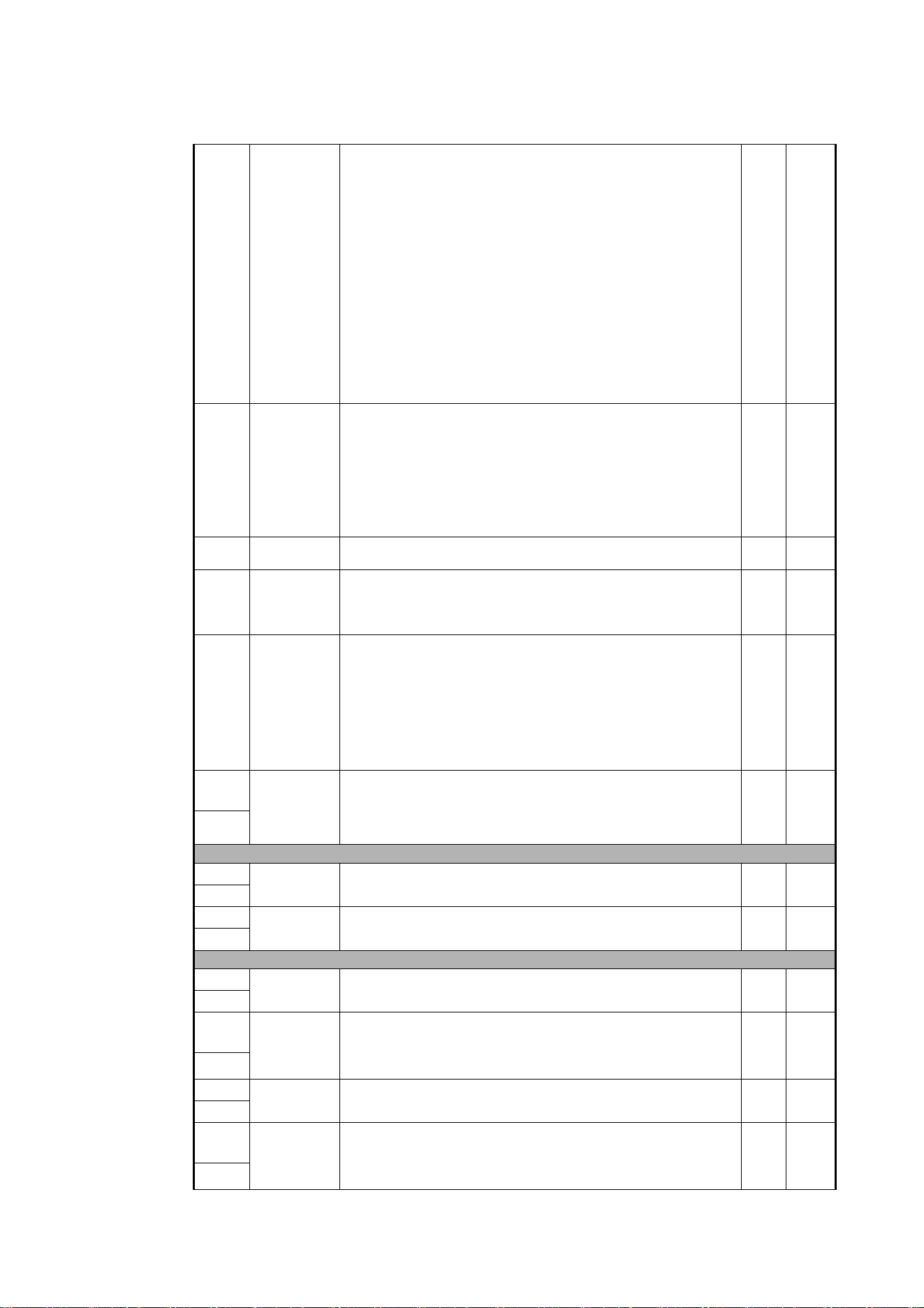
DMX protocol
37
19
0 - 5
6 - 10
11 - 15
16 - 20
21 - 25
26
27 - 59
60
61 - 109
110
111
112 - 198
199
200 - 254
255
Animation wheel indexing /rotation
Open
Horizontal position indexed
Horizontal position rotation
Vertical position rotation
Vertical position indexed
Angled rotation (set direction and speed on Channel 20)
Angled rotation - Wheel outside gate
Angled rotation - Wheel moving into gate
Angled rotation - Wheel in horizontal position
Angled rotation - Wheel in angled position
Angled rotation - Wheel in vertical position
Angled indexing (set indexing angle on Channel 20)
Angled indexing - Wheel in vertical position
Angled indexing - Wheel in angled position
Angled indexing - Wheel in horizontal position
Angled indexing - Wheel moving out of gate
Angled indexing - Wheel outside gate
Snap 0
20
0 - 255
0 - 2
3 - 126
127 - 129
130 - 253
254 - 255
Animation wheel indexed position/rotation speed
Indexed position
Position, min. → max.
Rotation speed and direction
Stop, indexed at 0°
Continuous rotation CW fast → slow
Stop, wheel stops at current position
Continuous rotation CCW slow → fast
Stop, indexed at 90°
Fade 128
21
0 - 255
Frost
No frost → full frost
Fade 0
22
0 - 10
11 - 138
139 - 255
Prism indexing/rotation
Open
Indexed position
Rotation
Snap 0
23
0 - 255
0 - 2
3 - 126
127 - 129
130 - 253
254 - 255
Prism indexed position/rotation speed
Indexed position
Position, min. → max. (128 = index 0°)
Rotation speed and direction
Stop, indexed at 0°
Continuous rotation CW fast → slow
Stop, prism stops at current position
Continuous rotation CCW slow → fast
Stop, indexed at 45°
Fade 128
24
0 - 51400
51401 - 57825
57826 - 59110
59111 - 65535
Iris
Open → closed
Animate fast → slow
Iris stops at current position
Animate reverse slow → fast
Fade 0
25
Zoom / Focus
26
0 - 65535
Zoom (16-bit)
Wide → narrow
Fade 32768
27
28
0 - 65535
Focus (16-bit)
Infinity → near
Fade 32768
29
Framing
30
0 - 65535
Framing blade 1 (top): position
Out → in
Fade 0
31
32
0 -32766
32767 - 32768
32769 - 65535
Framing blade 1 (top): angle
Angle –
Parallel
Angle +
Fade 32768
33
34
0 - 65535
Framing blade 2: (right-hand) position
Out → in
Fade 0
35
36
0 -32766
32767 - 32768
32769 - 65535
Framing blade 2:(right-hand) angle
Angle –
Parallel
Angle +
Fade 32768
37
Channel DMX Value Function
Fade
type
Default
value
Table 3: MAC Ultra Performance Extended Mode DMX Protocol
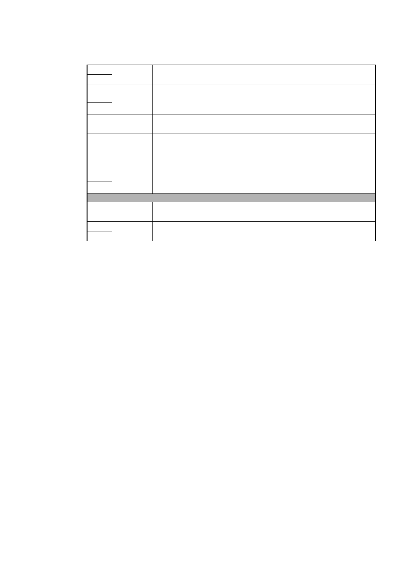
38
MAC Ultra Performance User Guide
38
0 - 65535
Framing blade 3 (bottom): position
Out → in
Fade 0
39
40
0 -32766
32767 - 32768
32769 - 65535
Framing blade 3 (bottom): angle
Angle –
Parallel
Angle +
Fade 32768
41
42
0 - 65535
Framing blade 4: (left-hand) position
Out → in
Fade 0
43
44
0 -32766
32767 - 32768
32769 - 65535
Framing blade 4: (left-hand) angle
Angle –
Parallel
Angle +
Fade 32768
45
46
0 -32766
32767 - 32768
32769 - 65535
Framing module angle
Angle –
Parallel
Angle +
Fade 32768
47
Movement
48
0 - 65535
Pan (16-bit)
Left → right
Fade 32768
49
50
0 - 65535
Tilt (16-bit)
Forward → backward
Fade 32768
51
Channel DMX Value Function
Fade
type
Default
value
Table 3: MAC Ultra Performance Extended Mode DMX Protocol

DMX protocol
39
Control / Settings
52
0 - 9
10 - 14
15
16
17
18
19 - 22
23
24
25
26
27
28
29
30
31
32
33
34
35
36
37
38
39
40
41 - 51
52
53
54
55
56
57
58
59 - 60
Fixture control/settings
(hold for number of seconds indicated to activate)
Exit calibration adjustment and return to normal control – 5 sec.
Reset entire fixture – 5 sec.
No function
Reset color – 5 sec.
Reset beam only – 5 sec.
Reset pan and tilt only – 5 sec.
No function
Linear dimming curve – 1 sec.
(menu override, setting unaffected by power off/on)
Square law dimming curve – 1 sec.
(menu override, default setting, setting unaffected by power off/on)
Inverse square law dimming curve – 1 sec.
(menu override, setting unaffected by power off/on)
S-curve dimming curve – 1 sec.
(menu override, setting unaffected by power off/on)
Standard pan and tilt speed – 1 sec. (default setting)
Fast pan and tilt – 1 sec.
(menu override - setting returns to Standard pan and tilt speed after
power on/off)
Smooth pan and tilt – 1 sec.
(menu override - setting returns to Standard pan and tilt speed after
power on/off)
Effect shortcuts on (default setting)
Effect shortcuts off
Disable focus tracking – 1 sec.
Focus tracking = Near distance – 1 sec.
Focus tracking = Medium distance (default setting) – 1 sec.
Focus tracking = Far distance – 1 sec.
Enable video tracking
Disable video tracking (default setting)
Extended gamut mode – 1 sec.
Calibrated color mode – 1 sec.
Raw color mode (default setting) – 1 sec.
No function
Control panel display on (default setting) – 1 sec.
Control panel display off – 1 sec.
Regulated fan speed, fixed light output intensity (default setting) – 1 sec.
Full fan speed, regulated light output intensity – 1 sec.
Medium fan speed, regulated light output intensity – 1 sec.
Low fan speed, regulated light output intensity – 1 sec.
Ultra-low fan speed, regulated light output intensity – 1 sec.
No function
Snap 0
Channel DMX Value Function
Fade
type
Default
value
Table 3: MAC Ultra Performance Extended Mode DMX Protocol

40
MAC Ultra Performance User Guide
52
contd.
61
62
63
64
65
66
67
68
69
70
71
72
73
74
75
76
77 - 78
79
80
81 - 86
87
88
89
90 - 93
94
95
96 - 99
100
101
102
103
104
105
106
107
108
109
110
111
112
113
114
115
116 - 193
194
195
196
197
198
199
200 - 255
Hibernation mode on – 1 sec.
Hibernation mode off – 1 sec.
Followspot mode on – 5 sec.
Followspot mode off (default setting) – 5 sec.
Pan and tilt limits on – 1 sec.
Pan and tilt limits off (default setting) – 1 sec.
Pan limit low – 1 sec.
Pan limit high – 1 sec.
Tilt limit low – 1 sec.
Tilt limit high – 1 sec.
Reset pan and tilt limits – 1 sec.
Tungsten emulation on – 1 sec.
Tungsten emulation off (default setting) – 1 sec.
Scene capture record – 5 sec.
Scene capture playback on – 5 sec.
Scene capture playback off (default setting) – 5 sec.
No function
Gobo CT correction on (default setting) – 1 sec.
Gobo CT correction off – 1 sec.
No function
Keylight calibration disabled – 1 sec.
Keylight calibration manual – 1 sec.
Keylight calibration automatic (default setting) – 1 sec.
No function
Framing mode = Standard – 1 sec.
Framing mode = Legacy – 1 sec.
No function
Enable calibration adjustment – 5 sec.
Store pan and tilt calibration – 5 sec.
Store dimmer calibration – 5 sec.
Store Cyan calibration – 5 sec.
Store Magenta calibration – 5 sec.
Store Yellow calibration – 5 sec.
Store CTC calibration – 5 sec.
Store all CMYC calibration – 5 sec.
Store rotating gobo wheel 1 calibration – 5 sec.
Store rotating gobo wheel 2 calibration – 5 sec.
Store animation wheel calibration – 5 sec.
Store framing system calibration – 5 sec.
Store iris calibration – 5 sec.
Store focus calibration – 5 sec.
Store zoom calibration – 5 sec.
Store color wheel calibration – 5 sec.
No function
Start CTO keylight calibration – 5 sec.
Start spectral enhancement keylight calibration – 5 sec.
Store CTO keylight enhancement keylight calibration – 5 sec.
Store spectral enhancement keylight calibration – 5 sec.
Store all calibration settings (except keylight settings) – 5 sec.
Return all calibration settings (except keylight settings) to factory
defaults – 5 sec.
No function
Snap 0
Channel DMX Value Function
Fade
type
Default
value
Table 3: MAC Ultra Performance Extended Mode DMX Protocol

DMX protocol
41
P3 Mix
53
0 - 26
27 - 228
229 - 255
P3 Mix
DMX Mode
Intensity and colors fully controlled by DMX, P3 pixel data ignored
Mixed Mode
Cross-fade from DMX control of intensity and colors to P3 control of
intensity and colors:
• At 27, intensity and colors are still fully controlled by DMX.
• Between 27 and 228, you mix/crossfade from DMX to P3 control.
• At 228, the Intensity of each of the 10 x Animotion segments is
controlled by 10 x separate P3 pixels and color is controlled by P3
Pixel 1 (the black pixel on the P3 map).
Video Mode
Intensity of 10 x Animotion segments controlled by P3, color controlled
by DMX (DMX channels ‘color’ the P3 pixel data)
Snap 0
Pre-programmed FX
54
0
1 - 254
255
FX1 selection (see FX table on page 44)
No effect
Effect selection (adjust speed and direction on channel 45)
Enable PWM frequency adjustment (adjust frequency on channel 45)
Snap 0
55
0 - 126
127 - 129
130 - 255
FX1 speed and direction
Effect reversed fast → slow
Effect stops
Effect forward slow → fast
Fade 128
56
0
1 - 159
160
161 - 194
195 - 254
255
FX2 selection (see FX table on page 44)
No effect
Effect selection (adjust speed and direction on channel 47)
Enable FX1 y-axis control on channel 47
No function (these FX are available for FX1 only)
Effect selection (adjust speed and direction on channel 47)
Enable PWM frequency adjustment (adjust frequency on channel 47)
Snap 0
57
0 - 126
127 - 129
130 - 255
FX2 speed and direction
Effect reversed fast → slow
Effect stops
Effect forward slow → fast
Fade 128
Channel DMX Value Function
Fade
type
Default
value
Table 3: MAC Ultra Performance Extended Mode DMX Protocol

42
MAC Ultra Performance User Guide
58
0
1
2
3
4
5
6
7
8
9
10
11
12
13
14
15
16
17
18
19
20
21
22
23
24
25
26
27
28
29
30
31
32
33
34
35
36
37 - 100
101 - 120
121 - 140
141 - 255
FX synchronization
No sync
Offset shift 10°
Offset shift 20°
Offset shift 30°
Offset shift 40°
Offset shift 50°
Offset shift 60°
Offset shift 70°
Offset shift 80°
Offset shift 90°
Offset shift 100°
Offset shift 110°
Offset shift 120°
Offset shift 130°
Offset shift 140°
Offset shift 150°
Offset shift 160°
Offset shift 170°
Offset shift 180°
Offset shift 190°
Offset shift 200°
Offset shift 210°
Offset shift 220°
Offset shift 230°
Offset shift 240°
Offset shift 250°
Offset shift 260°
Offset shift 270°
Offset shift 280°
Offset shift 290°
Offset shift 300°
Offset shift 310°
Offset shift 320°
Offset shift 330°
Offset shift 340°
Offset shift 350°
Synchronized: all fixtures start FX cycles at same time
No function
Random start (Channel 45 controls overall speed)
Random duration
No function
Snap 36
Channel DMX Value Function
Fade
type
Default
value
Table 3: MAC Ultra Performance Extended Mode DMX Protocol

FX: pre-programmed effects
43
FX: pre-programmed effects
FX are implemented from MAC Ultra Performance firmware version 1.5.0. You can quickly check
which firmware version a fixture is running using INFORMATION
→
FW VERSION in the fixture’s
control menus. For information on updating firmware, see the MAC Ultra Performance Safety and
Installation Manual supplied with the fixture and available for download from www.martin.com.
The table on the following pages lists the pre-programmed dynamic FX (effect macros) available in the MAC
Ultra Performance. To control the FX you can:
• Select an effect, or two effects that can run simultaneously, on DMX channels 44 and 46 (Basic Mode) or
54 and 56 (Extended Mode) by sending the values listed in the table.
• Adjust effect speed on channels 45 and 47 (Basic Mode) or 55 and 57 (Extended Mode).
• Adjust synchronization of effects across different fixtures on channel 48 (Basic Mode) or 58 (Extended
Mode).
Effects types
Intensity FX (1-15)
These effects modulate the intensity of the output while keeping the color(s) set on the CMY and color
wheel channels and any other effects applied.
Animotion effects (32-46)
The MAC Ultra Performance’s Animotion effects modulate the ten individual segments of the fixture's LED
engine individually, leading to unique animated effects.
Color FX (64-91)
These effects override the color(s) set on the CMY and color wheel channels.
Beam shaping FX (96-110)
These effects use the fixture’s iris, zoom and prism to dynamically change the shape of the beam.
Gobo FX (128-143)
These effects apply dynamic movement to gobos. Certain effects add zoom to the movement.
Gobo 1 FX are applied to the gobo that is currently selected on gobo wheel 1 and Gobo 2 FX are applied to
the gobo that is currently selected on gobo wheel 2.
Framing FX (160-194)
These effects use the fixture’s framing system to give static and dynamic beam shapes.
FX 160, FX2 y-axis selection, is available on the FX2 Selection channel 46 in Basic Mode / 56 in Extended
Mode only. Selecting FX 160 on channel 46 / 56 changes the function of channel 47 / 57. If you select FX
160 on channel 46 / 56, channel 47 / 57 now lets you adjust the y-axis of any FX from 161 - 194 that you
select on the FX1 Selection channel 44 / 54.
FX 161 - 194 are available on the FX1 Selection channel 44 (Basic Mode) / 54 (Extended Mode) only.
Pan and tilt FX (224-235)
These effects use pan and tilt to move the beam following pre-programmed shapes.
PWM Tune (255)
Sending DMX value 255 on one of the FX selection channels 44 or 46 (Basic Mode) / 54 or 56 (Extended
Mode lets you adjust the LED PWM frequency. See “LED PWM frequency control” on page 11 for details.
44
MAC Ultra Performance User Guide
Effects types
Available from MAC Ultra Performance firmware version 1.5.0.
DMX
value
Effect
0No FX
Intensity FX
1 Strobe Pulse Width (when Strobe is activated on Channel 1)
2 Wave (sine wave)
3 Step (50/50 on/off)
4Pulse
5 Blackout Strobe
6 2x Strobe
7 3x Strobe
8 4x Strobe
9 Up, Down, Flash
10 Up, Flash, Down, Flash
11 Random Levels
12 Electric Arc
13 Atomic Lighting
14 Thunderstorm
15 Welding
16 - 31 No function
Animotion FX
32 Stop Motion
33 Movie Flicker
34 Random Dimmers
35 Shakey Dimmers
36 Negative Pulse
37 Positive Pulse
38 Radar Wave
39 Radar Step
40 Radar Pulse
41 Odd/Even Wave
42 Odd/Even Step
43 Odd/Even Pulse
44 5-Step Wave
45 5-Step Step
46 5-Step Pulse
47 - 63 No function
Color FX
64 Rainbow Wave
65 Rainbow Step
66 Rainbow Pulse
67 RGB Wave
68 RGB Step
69 RGB Pulse
70 CMY Wave
71 CMY Step
72 CMY Pulse
73 Mix to White Wave
74 Mix to White Step
Table 4: FX in the MAC Ultra Performance
FX: pre-programmed effects
45
75 Mix to White Pulse
76 Random Mix Wave
77 Random Mix Step
78 Random Mix Pulse
79 Random Subtle Wave
80 Red White Blue Fade
81 Red White Blue Snaps
82 Full Bumps
83 All Bumps
84 Split Bumps
85 Random Split Bumps
86 Color Shaker
87 Fire
88 Water
89 Ice
90 Hot and Cold
91 Warm and Fuzzy
92 - 95 No function
Beam Shaping FX
96 Iris Wave (sine wave)
97 Iris Step (50/50 on/off)
98 Iris Pulse
99 Zoom Wave (sine wave, keeps current speed mode)
100 Zoom Step (50/50 on/off, keeps current speed mode)
101 Zoom Pulse (keeps current speed mode)
102 Random Size Wave
103 Random Size Step
104 Random Size Pulse
105 Prism Quarter Tick Tock
106 Prism Half Tick Tock
107 Prism Full Tick Tock
108 Beam Splash
109 Beam Splash Invert
110 Pin to Flood (keeps current speed mode)
111 - 127 No function
Gobo and Animation FX
128 Gobo 1 Tick Tick Tick
129 Gobo 1 Quarter Tick Tock
130 Gobo 1 Half Tick Tock
131 Gobo 1 Full Tick Tock
132 Gobo 1 Fade Spin Zoom
133 Gobo 1 Twist
134 Gobo 1 Expand Twist
135 Gobo 1 Collapse Twist
136 Gobo 2 Tick Tick Tick
137 Gobo 2 Quarter Tick Tock
138 Gobo 2 Half Tick Tock
139 Gobo 2 Full Tick Tock
140 Gobo 2 Fade Spin Zoom
141 Gobo 2 Twist
142 Gobo 2 Expand Twist
143 Gobo 2 Collapse Twist
144 - 159 No function
Table 4: FX in the MAC Ultra Performance

46
MAC Ultra Performance User Guide
Framing FX
160 When selected on channel 46, FX160 enables y-axis selection
on channel 47 for FX 167-194 if one of these is selected on
channel 44.
161 Vertical Bar Slim
162 Vertical Bar Medium
163 Vertical Bar Large
164 Horizontal Bar Slim
165 Horizontal Bar Medium
166 Horizontal Bar Large
167 Small Square
168 Medium Square
169 Large Square
170 Small Horizontal Rectangle
171 Medium Horizontal Rectangle
172 Large Horizontal Rectangle
173 Small Vertical Rectangle
174 Medium Vertical Rectangle
175 Large Vertical Rectangle
176 Small Parallelogram Left
177 Medium Parallelogram Left
178 Small Parallelogram Right
179 Medium Parallelogram Right
180 Vertical Bar Slim to Horizontal Bar Slim
181 Vertical Bar Medium to Horizontal Bar Medium
182 Vertical Bar Large to Horizontal Bar Large
183 Vertical Bar Slim to Medium Square
184 Vertical Bar Medium to Medium Square
185 Horizontal Bar Slim to Medium Square
186 Horizontal Bar Medium to Medium Square
187 Medium Square to Medium Horizontal Rectangle
188 Medium Square to Medium Vertical Rectangle
189 Medium Square to Large Horizontal Rectangle
190 Medium Square to Large Vertical Rectangle
191 Small Square to Small Parallelogram Left
192 Medium Square to Medium Parallelogram Left
193 Small Square to Small Parallelogram Right
194 Medium Square to Medium Parallelogram Right
195 - 223 No function
Table 4: FX in the MAC Ultra Performance

FX: pre-programmed effects
47
Pan/Tilt FX
224 Pan and Tilt Circle Small
225 Pan and Tilt Circle Medium
226 Pan and Tilt Circle Large
227 Pan and Tilt Figure 8 Small
228 Pan and Tilt Figure 8 Medium
229 Pan and Tilt Figure 8 Large
230 Pan and Tilt Diagonal Line Small
231 Pan and Tilt Diagonal Line Medium
232 Pan and Tilt Diagonal Line Large
233 Pan and Tilt Square Small
234 Pan and Tilt Square Medium
235 Pan and Tilt Square Large
236 - 254 No function
Full fixture
255 PWM Tune
Table 4: FX in the MAC Ultra Performance
48
MAC Ultra Performance User Guide
Control panel menus
MAC Ultra Performance firmware version 2.3.x.
The menu items marked * such as the TEMPERATURES, DMX LIVE, MANUAL CONTROL and SERVICE menus are not
available when the fixture is operating on battery power.
Menu level 1 Menu level 2 Menu level 3 Menu level 4 Notes (Default settings in bold print)
DMX SETUP
DMX ADDRESS 1 – XXX
DMX address (default address = 1). The
DMX address range is limited so that the
fixture will always have enough DMX
channels within the 512 available.
CONTROL MODE
BASIC Basic DMX control mode
EXTENDED Extended DMX control mode
COMPACT Compact DMX mode
DMX UNIVERSE 1 - 64000 Set DMX universe
ETHERNET
SETUP
IP ADDRESS
XXX.XXX.XXX.XXX Display fixture’s static IP address
PA RT 1 M SB
Set far left block (most significant byte) of
IP address
PART 2 Set middle left block of IP address
PART 3 Set middle right block of IP address
PART 4 LSB
Set far right block (most significant byte) of
IP address
SUBNET MASK
XXX.XXX.XXX.XXX Display fixture’s subnet mask
EDIT SUBNET
MASK
XXX.XXX.XXX.XXX
Display fixture’s subnet mask
XXX.XXX.XXX.XXX
Set subnet mask with 1 bit increments
from the left
MAC ADDRESS XX:XX:XX:XX:XX:XX Display fixture’s MAC address
RESET IP SETUP RESET
ARE YOU SURE?
YES/NO
Reset static IP address and subnet mask
to default values
FIXTURE ID 0 – 9999
User-settable 4-digit fixture ID number
(default = 0)
PERSONALITY PAN/TILT
PAN INVERT ON/OFF Inverse DMX pan control: right → left
TILT INVERT ON/OFF Inverse DMX tilt control: down → up
FOLLOWSPOT
MODE
ON/OFF
Enable followspot mode: pan/tilt motors
disabled, head can be moved manually
LIMIT PAN/TILT
LIMIT ENABLE
ON/OFF
Enable limits for pan and tilt
PA N MI N →
-32767
Set minimum pan angle limit
PAN MAX →
32768
Set maximum pan angle limit
TILT MIN →
-32767
Set minimum tilt angle limit
TILT MAX →
32768
Set maximum tilt angle limit
RESET PAN/TILT
LIMITS
Confirm with: ARE YOU SURE? YES/NO
Returns fixture to default pan/tilt limits. The
default limits match GT Truss with
half-coupler rigging clamps.
Table 5: Control menus

Control panel menus
49
PERSONALITY
(continued)
SPEED
PA N /T ILT
FAST Optimize pan/tilt movement for speed
SMOOTH
Optimize pan/tilt movement for
smoothness
STANDARD
Standard pan/tilt movement, balances
speed and smoothness
EFFECT
FAST Optimize effects movement for speed
SMOOTH
Optimize effects movement for
smoothness
STANDARD
Standard effects movement, balances
speed and smoothness
FOLLOW P/T
Effects speed follows the speed setting
applied to pan and tilt via DMX or in
control menu
DIMMER CURVE
LINEAR Optically linear dimming curve
SQUARE LAW Square law dimming curve
INV SQ LAW Inverse square law dimming curve
S-CURVE
S-curve (fixture emulates incandescent
lamp voltage linear RMS dimming curve)
TUNGSTEN
EMULATOR
ON
Color temperature and dimming
characteristics emulate tungsten lamp
behavior
OFF
COLOR MODE
RAW Direct control of CMY flags
CALIBRATED
CMY flag calibration active; color across
fixtures is even but deepest color
saturation may not be available
EXTENDED GAMUT
Gives combination of calibrated colors and
deep color saturation
FOCUS
TRACKING
FAR
Focus adjusts to match zoom: optimized
for long range projection
MEDIUM
Focus adjusts to match zoom: optimized
for mid-range projection
NEAR
Focus adjusts to match zoom: optimized
for close range projection
DISABLED Focus tracking function disabled
VIDEO
TRACKING
ENABLED
Color fading optimized for speed of color
changes
DISABLED Color fading optimized for smoothness
DMX RESET
ON Fixture can be reset via DMX
OFF
Fixture cannot be reset via DMX (note that
this menu item can be overridden: see
DMX protocol)
EFFECT
SHORTCUT
ON
Effects take shortest route during
changes, crossing open positions if
necessary
OFF
Effects avoid open positions during effects
changes
Menu level 1 Menu level 2 Menu level 3 Menu level 4 Notes (Default settings in bold print)
Table 5: Control menus
50
MAC Ultra Performance User Guide
PERSONALITY
(continued)
COOLING MODE
CONSTANT FAN FULL
Fans optimized for maximum light intensity,
fans run at full speed, light intensity
reduced if necessary to keep fixture within
temperature limits
CONSTANT FAN MEDIUM
Fans run at medium speed, light intensity
reduced if necessary to keep fixture within
temperature limits
CONSTANT FAN LOW
Fans run at low speed, light intensity
reduced if necessary to keep fixture within
temperature limits
CONSTANT FAN ULOW
Fans optimized for lowest noise, fans run
at ultra-low speed, light intensity reduced if
necessary to keep fixture within
temperature limits
REGULATE FANS
Compromise between light intensity
and quietness, fan speed
temperature-regulated, light intensity
only reduced if fans reach full speed
and further action necessary to keep
fixture within temperature limits
GOBO CT
CORRECTION
ENABLED
Automatic color temperature correction
when gobo is inserted into beam
DISABLED No automatic color temperature correction
DISPLAY
DISPLAY SLEEP
10 MINUTES
Display goes into sleep mode 10 minutes
after last key press
5 MINUTES
Display goes into sleep mode five minutes
after last key press
2 MINUTES
Display goes into sleep mode two
minutes after last key press
ON Display permanently on
DISPLAY
INTENSITY
10 ... 100 % Set display intensity in % (default = 100)
DISPLAY
ROTATION
NORMAL Display orientation normal
ROTATE 180 Display orientation rotated 180°
DISPLAY
CONTRAST
3 ... 41 ... 100 Adjust contrast of display (default = 41)
ERROR MODE
NORMAL
Enable error messages and warnings in
display
SILENT
Disable error messages and warnings in
display (the status LED will still light to
indicate fixture status if an error has been
detected or the fixture has a warning)
HIBERNATION
MODE
ON
Enable Hibernation Mode (light output set
to zero, all effect movement disabled)
OFF
Disable Hibernation Mode
FRAMING MODE
LEGACY
Blade insertion is limited so that max.
DMX value for insertion gives 50%
insertion. Corners of angled blades also
reach max. 50% insertion.
STANDARD
Framing is controlled with designated
primary and secondary blades. Secondary
blades must make room for primary
blades, with angle as first priority.
SCENE CAPTURE
RECORD
SAVE
Saves all current DMX values as playback
scene
PLAYBACK
ENABLE
Sets fixture to run currently saved
playback scene after power cycle / reset.
Any new DMX input disables scene
playback until next power cycle.
DISABLE Disable scene playback functionality
Menu level 1 Menu level 2 Menu level 3 Menu level 4 Notes (Default settings in bold print)
Table 5: Control menus

Control panel menus
51
DEFAULT
SETTINGS
FACTORY
DEFAULT
LOAD
ARE YOU SURE?
YES/NO
Return all settings (except calibrations) to
factory defaults
CUSTOM 1
LOAD
ARE YOU SURE?
YES/NO
Load Custom Settings 1
SAVE
ARE YOU SURE?
YES/NO
Save fixture’s current settings as Custom
Settings 1
CUSTOM 2
LOAD
ARE YOU SURE?
YES/NO
Load Custom Settings 2
SAVE
ARE YOU SURE?
YES/NO
Save fixture’s current settings as Custom
Settings 2
CUSTOM 3
LOAD
ARE YOU SURE?
YES/NO
Load Custom Settings 3
SAVE
ARE YOU SURE?
YES/NO
Save fixture’s current settings as Custom
Settings 3
INFORMATION
POWER ON TIME
TOTAL 0 ... XXX HR
Display hours fixture has been powered on
since manufacture (not user-resettable)
RESETTABLE
CLEAR
COUNTER?
YES/NO
Display hours fixture has been powered on
since last counter reset (user-resettable)
POWER ON
CYCLES
TOTAL 0 ... XXX HR
Display number of times fixture has been
powered on since manufacture
(not user-resettable)
RESETTABLE
CLEAR
COUNTER?
YES/NO
Display number of times fixture has been
powered on since last counter reset
(user-resettable)
LED ON TIME
TOTAL 0 ... XXX HR
Display number of hours LEDs have been
powered on since manufacture
(not user-resettable)
RESETTABLE
CLEAR
COUNTER?
YES/NO
Display number of hours LEDs have been
powered on since last counter reset
(user-resettable)
FW VERSION* XX.XX.XX Displays currently active firmware version
RDM UID* 4D50.XXXXXXXX Displays fixture’s unique RDM ID
FAN SPEEDS*
HEAD FAN 1 -12
BASE FAN 1 - 4
0 - XXX RPM
Scroll to display current speed of each
cooling fan (head and base)
TEMPERA-
TURES*
UI ... CURRENT
DRIVER
CURRENT / MIN /
MAX X C
Scroll through PCB temperature sensors,
then display current, minimum* and
maximum* temperature in °C of all PCBs
*Since fixture was last reset / powered on
DMX LIVE*
RATE 0 - 44 HZ
DMX transmission speed in packets per
second
QUALITY 0 - 100% Percent of packets received
START CODE 0 - 255 Value of the DMX start code
STROBE ... FX
SYNC
XXX
Scroll to see values received on each DMX
channel
TEST*
TEST ALL DIMMER ... TILT
Run test sequence of all functions
To test a specific function, use Up/Down
buttons to scroll through functions. Press
Enter to pause and press again to restart
test sequence.
Press Menu button to exit test
TEST LEDS DIMMER
Run test sequence of LEDs only.
Press Menu button to exit test
TEST EFFECTS CMY ... FOCUS
Run test sequence of effects.
To test a specific effect, use Up/Down
buttons to scroll through groups. Press
Enter to pause and press again to restart
test sequence.
Press Menu button to exit test
TEST PAN/TILT
PA N
Run test sequence of pan functions.
Press Menu button to exit test
TILT
Run test sequence of tilt functions.
Press Menu button to exit test
Menu level 1 Menu level 2 Menu level 3 Menu level 4 Notes (Default settings in bold print)
Table 5: Control menus

52
MAC Ultra Performance User Guide
MANUAL
CONTROL*
RESET
ALL Reset fixture
STROBE / SHUTTER ... P3 MIX MODE
Scroll through effects, then manually
control an effect
SERVICE*
(see “Activating
service mode” on
page 14)
ERROR LIST Empty or up to 20 errors
Show all error and warning messages
stored in memory.
FAN CLEAN ON/OFF
Run cooling fans at high speed to dislodge
dust and debris.
COLOR CAL DATA
AUTOMATIC Calibration data chosen automatically
MAIN BOARD
Fixture uses calibration data on main
board
LIGHT ENGINE
Fixture uses calibration data on light
engine
DEFAULT 1 ... 5
Fixture uses one of five factory calibration
presets
PA N /T ILT
FEEDBACK
ON
Enable pan/tilt position feedback
system
OFF Disable pan/tilt position feedback system
ADJUST
(for use by or with
guidance from
Martin Service
only)
P/T AUTO-
CALIBRATION
PRESS UP →
START
Allow room for full pan/tilt movement
before start
PA N /T ILT AT EN D
STOP
STEP 1
To adjust, move head to end position and
press ENTER
STEP 2
To adjust, move head to end position again
and press ENTER
FROST
NOT ADJUSTED
Adjust full frost position
0 - 255
CALIBRATION
CYAN
...
TILT
Calibration range
varies depending
on effect
Scroll through effects, press Enter to
select. Adjust position and press Enter to
confirm.
LOAD DEFAULTS LOAD Load factory default calibration settings
SAVE DEFAULTS SAVE
Replace factory default calibration settings
with current calibration settings
EXPECTED
MODULES
MODULE STATUS
PAN ... PIXEL
BEAM 1
FOUND /
MISSING
Lists internal effect modules that the fixture
expects to detect and reports them as
either FOUND or MISSING
UNKNOWN
MODULE
NONE AVAILABLE
Every module has been detected as
UKNOWN
XXXX (PAN ...
PIXEL BEAM 1)
One module is displayed with a red
flashing LED – identify which module is
has the flashing LED and choose the
module from the UNKNOWN module list to
make it KNOWN
DELETE MODULE
PAN ... PIXEL
BEAM 1
CAUTION! Deletes module type ID.
Module will now be detected as
UNKNOWN
SERVICE LOG
NO DEVICE / EXPORT
No USB device present
Press ENTER to export Service Log data
to USB device
CLEAR
ARE YOU SURE?
YES/NO
Clears all saved error data
USB
NO DEVICE
No USB memory device detected at USB
port or no firmware detected on USB
memory device
UPDATING FILES
Fixture updating internal memory from
USB memory device
AVAILABLE
FIRMWARE
XX.XX.XX ...
XX.XX.XX
Select firmware from versions stored in
internal memory. Scroll to select version,
then press Enter and confirm your choice
to update.
Menu level 1 Menu level 2 Menu level 3 Menu level 4 Notes (Default settings in bold print)
Table 5: Control menus

Service and display messages
53
Service and display messages
The MAC Ultra Performance gives service and maintenance information by displaying a large 3- or
4-character short code and a smaller full-text message in the fixture’s display. The short code is visible at a
distance, allowing easier reading with the fixture still in the rig, for example, while the full-text message gives
more detailed information.
Excessively high temperatures
If any of the temperature sensors reports that the fixture has exceeded its recommended temperature
range, the fixture reports a temperature warning and reduces light output to reduce its temperature. If the
temperature reaches a dangerous level, light output is shut down completely.
Temperature warnings are canceled and full light output becomes available again as soon as the
temperature returns to normal.
Warning messages
Warning messages indicate that either:
• problems might appear in the future if no action is taken, or
• the user needs to pay special attention to a function or procedure when working with the fixture.
The MAC Ultra Performance communicates warnings as follows:
• Warning codes are shown continuously in the display and disappear when the user reacts to the warning.
• If more than one warning is detected, all warnings are displayed in sequence.
• If the display is inactive, the fixture’s status LED (see Figure 5 on page 12) flashes orange to indicate that
there is a warning. Activating the display will show the warning.
The possible warning messages are listed in Table 6 below
:
Short code
Long message and explanation
BANK
BANK NO ACCESS
Error unpacking firmware bank during/after software upload. Fixture will continue to operate on
existing firmware. Warning message is cleared by a successful software upload or at the next
power off/on cycle.
BATM
BATTERY MODE
Fixture in battery mode. Certain control menu items are not available.
BETW
BEAM TMP HIGH
LED beam pixels sensor detects abnormally high operating temperature.*
CMTW
CMY TEMP HIGH
CMY module sensor detects abnormally high operating temperature.*
EFTW
EFF TEMP HIGH
Effects module sensor detects abnormally high operating temperature.*
F2TW
FRAMING2 TMP HIGH
Framing module sensor 2 detects abnormally high operating temperature.*
FRTW
FRAMING TMP HIGH
Framing module sensor 1 detects abnormally high operating temperature.*
FTNA
FROST ADJUST
Frost effect out of adjustment range.
G11M
GOBO 1-1 MISSING
Gobo Wheel 1: Gobo 1 not detected.
G21M
GOBO 2-1 MISSING
Gobo Wheel 2: Gobo 1 not detected.
Table 6: Warning messages

54
MAC Ultra Performance User Guide
*High temperature warnings are canceled as soon as temperature returns to normal. If temperature reaches
cutoff level, the warning is replaced by a cutoff error message.
Error messages
Error messages indicate that a problem is present. The MAC Ultra Performance communicates errors as
follows:
• Error messages flash in the display.
• If more than one error is detected, the fixture flashes all errors three times each.
• Errors are shown in the display regardless of display status: they override an inactive display and any
other information that the display might be showing.
• If an error is present, the status LED flashes red.
The possible error messages are listed in Table 7 below
:
LDTW
LED DRV TMP HIGH
LED Driver PCB sensor detects abnormally high operating temperature.*
LETW
LED BOARD TEMP HIGH
LED PCB sensor detects abnormally high operating temperature.*
PNTW
PAN TEMP HIGH
Pan motor sensor detects abnormally high operating temperature.*
PUTW
PSU TEMP HIGH
PSU sensor detects abnormally high operating temperature.*
SERV
SERVICE MODE
Fixture in service mode.
TLTW
TILT TEMP HIGH
Tilt motor sensor detects abnormally high operating temperature.*
UITW
UI TEMP HIGH
User interface (LCD display and control panel) PCB sensor detects abnormally high operating
temperature.*
ZFTW
ZF TEMP HIGH
Zoom/focus PCB sensor detects abnormally high operating temperature.*
Short code
Long message and explanation
APER
AW POS ERROR
Animation Wheel position error.
ARER
AW ROT ERROR
Animation Wheel rotation error.
BCER
BEAM CALIB ERR
No calibration data on main board – fixture will switch to ‘average’ calibration values, and color
may not match exactly between multiple fixtures
BETC
BM TMP CUT OFF
LED beam pixels temperature cutoff activated.
BETE
BM TMP SEN ERR
LED beam pixels temperature sensor error.
C1ER
COLORWHEEL 1 ERR
Color Wheel error.
CECM
COM ERR CMY
CMY module communication error.
CEEF
COM ERR EFFECT
Effects module communication error.
CELD
COM ERR LED DRV
LED driver communication error.
Table 7: Error messages
Short code
Long message and explanation
Table 6: Warning messages

Service and display messages
55
CEPN
COM ERR PAN
Pan system communication error.
CETL
COM ERR TILT
Tilt system communication error.
CEZF
COM ERR Z/F
Zoom/focus effect communication error.
CMTC
CMY TEMP CUTOFF
CMY module temperature cutoff activated.
CMTE
CMY TEMP SEN ERR
CMY module temperature sensor error.
COLD
FIXTURE COLD
Fixture too cold. Physical movement of effects is disabled until fixture has warmed up.
CTER
CTC ERROR
CTC flag position error.
CYER
CYAN ERROR
Cyan flag position error.
EFTC
EFF TEMP CUTOFF
Effects module temperature cutoff activated.
EFTE
EFF TEMP SEN ERR
Effects module temperature sensor error.
F2TC
FROST TEMP CUTOFF
Frost effect temperature cutoff activated.
F2TE
FROST TEMP SEN ERR
Frost effect temperature sensor error.
FAN BASE FAN 1 ERR
FAN BASE FAN 2 ERR
FAN BASE FAN 3 ERR
FAN BASE FAN 4 ERR
FAN HEAD FAN 1 ERR
FAN HEAD FAN 2 ERR
FAN HEAD FAN 3 ERR
FAN HEAD FAN 4 ERR
FAN HEAD FAN 5 ERR
FAN HEAD FAN 6 ERR
FAN HEAD FAN 7 ERR
FAN HEAD FAN 8 ERR
FAN HEAD FAN 9 ERR
FAN HEAD FAN 10 ERR
FAN HEAD FAN 11 ERR
FAN HEAD FAN 12 ERR
FBEP
PA N FB AC K E RR
Pan position magnetic indexing system timeout. Fixture is unable to correct pan position (but
pan movement will often still be possible).
FBET
TILT FBACK ERR
Tilt position magnetic indexing system timeout. Fixture is unable to correct tilt position (but tilt
movement will often still be possible).
FOER
FOCUS ERROR
Focus position error.
FRCE
FRAMING COM ERROR
Framing module communication error.
FRTC
FR TEMP CUTOFF
Framing module temperature cutoff activated.
Short code
Long message and explanation
Table 7: Error messages

56
MAC Ultra Performance User Guide
FSER
FRAMING1 INS ERR
Framing blade 1 insertion position error.
FSER
FRAMING1 ANG ERR
Framing blade 1 angle position error.
FSER
FRAMING2 INS ERR
Framing blade 2 insertion position error.
FSER
FRAMING2 ANG ERR
Framing blade 2 angle position error.
FSER
FRAMING3 INS ERR
Framing blade 3 insertion position error.
FSER
FRAMING3 ANG ERR
Framing blade 3 angle position error.
FSER
FRAMING4 INS ERR
Framing blade 4 insertion position error.
FSER
FRAMING4 ANG ERR
Framing blade 4 angle position error.
G1ER
GOBO W 1 ERR
Gobo Wheel 1 position error.
G2ER
GOBO W 2 ERR
Gobo Wheel 2 position error.
IRER
IRIS ERROR
Iris effect position error.
LDTC
LED TEMP CUTOFF
LED temperature cutoff activated.
LDTE
LED TEMP SEN ERR
LED temperature sensor error.
LETC
LED BOARD TMP CUTOFF
LED PCB temperature sensor cutoff activated.
LETE
LED BOARD SEN ERR
LED PCB temperature sensor error.
MAER
MAGENTA ERR
Magenta flag position error.
MMER
MISSING MODULE ERR
Impossible to communicate with a module that should be present. Module missing or not
correctly connected.
PAER
PA N ER ROR
Pan position electrical indexing system timeout.
PNTC
PAN TEMP CUTOFF
Pan motor temperature cutoff activated.
PNTE
PAN TEMP SEN ERR
Pan motor temperature sensor error.
PRIR
PRISM INS ERR
Prism insertion position error.
PRRO
PRISM ROT ERR
Prism rotation error.
PSER
PAN SENSOR ERROR
Fixture unable to retrieve reliable data from pan position sensor.
PTCM
P/T SENSOR ADJUST
Pan/tilt sensors are incorrectly adjusted.
PUTC
PSU TEMP CUTOFF
PSU temperature cutoff activated.
PUTE
PSU TEMP SEN ERR
PSU temperature sensor error.
R1ER
GOBO W 1 ROT ERR
Gobo Wheel 1 rotation error.
Short code
Long message and explanation
Table 7: Error messages

Service and display messages
57
R2ER
GOBO W 2 ROT ERR
Gobo Wheel 2 rotation error.
RFER
FRAM ROT ERR
Framing module rotation error.
SEER
ARTNET SOURCES EXCEED
Number of Art-Net control sources exceeded.
SEER
SACN SOURCES EXCEEDED
Number of sACN control sources exceeded.
SLER
SAFETY LOOP
Safety loop circuit activated. A temperature circuit breaker has shut down LEDs. Circuit breaker
resets automatically after temperature has returned to normal operating range.
TIER
TILT ERROR
Tilt position electrical indexing circuit timeout.
TLTC
TILT TEMP CUTOFF
Tilt motor temperature cutoff activated.
TLTE
TILT TEMP SEN ERR
Tilt motor temperature sensor error.
TSER
TILT SENSOR ERR
Fixture unable to retrieve reliable data from tilt position sensor.
UECM
UPL ERR CMY
Could not upload new CMY software during a firmware upload. Error cleared when new
firmware is uploaded successfully or power is cycled off and on.
UEEF
UPL ERR EFFECT
Could not upload new effects software during a firmware upload. Error cleared when new
firmware is uploaded successfully or power is cycled off and on.
UELD
UPL ERR LED DRV
Could not upload new LED driver software during a firmware upload. Error cleared when new
firmware is uploaded successfully or power is cycled off and on.
UEPN
UPL ERR PAN
Could not upload new pan system software during a firmware upload. Error cleared when new
firmware is uploaded successfully or power is cycled off and on.
UETL
UPL ERR TILT
Could not upload new tilt system software during a firmware upload. Error cleared when new
firmware is uploaded successfully or power is cycled off and on.
UEZF
UPL ERR Z/F
Could not upload new zoom/focus system software during a firmware upload. Error cleared
when new firmware is uploaded successfully or power is cycled off and on.
UITC
UI TEMP CUTOFF
User interface (LCD display and control panel) temperature cutoff activated.
UITE
UI TEMP SEN ERR
User interface (LCD display and control panel) temperature sensor error.
WEER
WASH EFFECT ERROR
Wash effect position error.
YEER
YELLOW ERROR
Yellow flag position error.
ZFTC
ZF TEMP CUTOFF
Zoom/focus module temperature cutoff activated.
ZFTE
ZF TEMP SEN ERR
Zoom/focus module temperature sensor error.
ZOER
ZOOM ERROR
Zoom car position error.
Short code
Long message and explanation
Table 7: Error messages
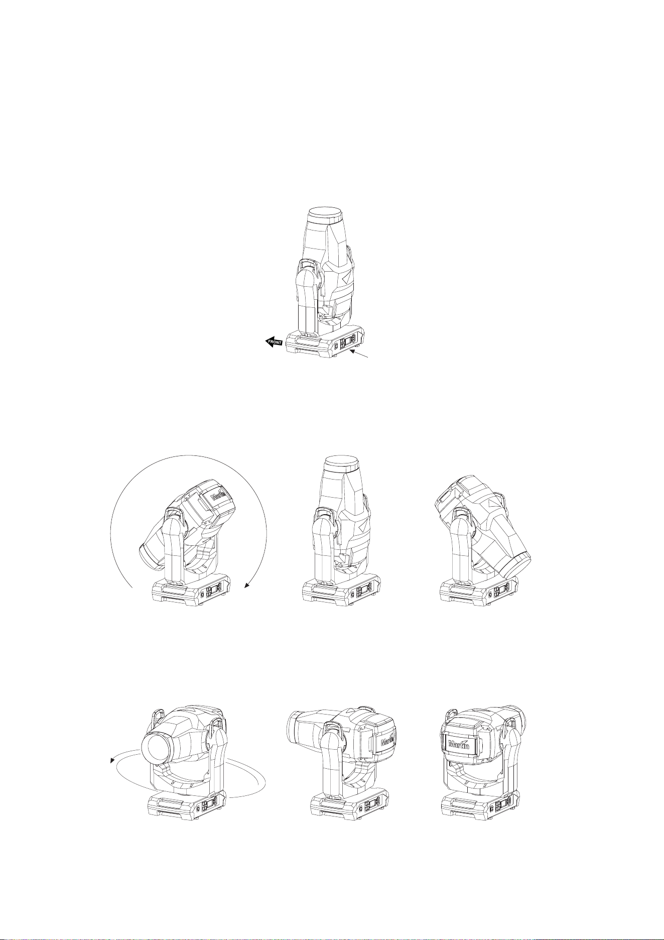
58
MAC Ultra Performance User Guide
Control orientation reference
Pan and tilt control
Tilt = DMX 0
Pan = DMX 32768
DMX 65535DMX 0
Tilt range = 268°
Tilt = DMX 32768
Tilt = DMX 65535
Pan range = 540°
DMX 0
DMX
65535
Tilt = DMX 10759
Pan = DMX 0 Pan = DMX 32768 Pan = DMX 65535
Pan = DMX 32768 Pan = DMX 32768
Tilt = DMX 10759 Tilt = DMX 10759
Home position / Front of fixture
Display
Power Input
DMX disconnected
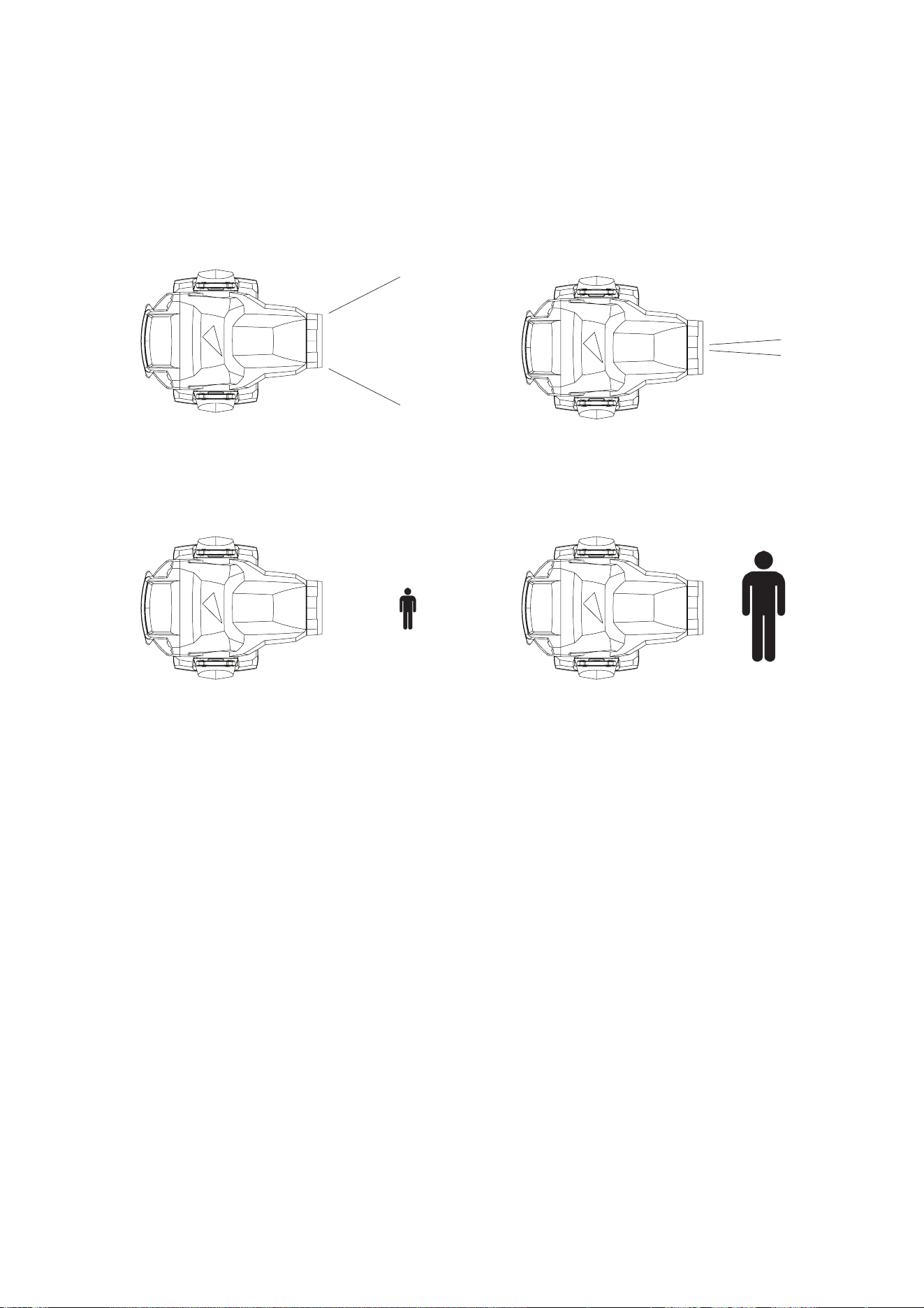
Control orientation reference
59
Zoom and focus control
Zoom
Zoom Narrow = DMX 65535Zoom Wide = DMX 0
Focus
Focus - 1HDUSURMHFWLRQ = DMX 65535Focus - )DU SURMHFWLRQ= DMX 0

www.martin.com
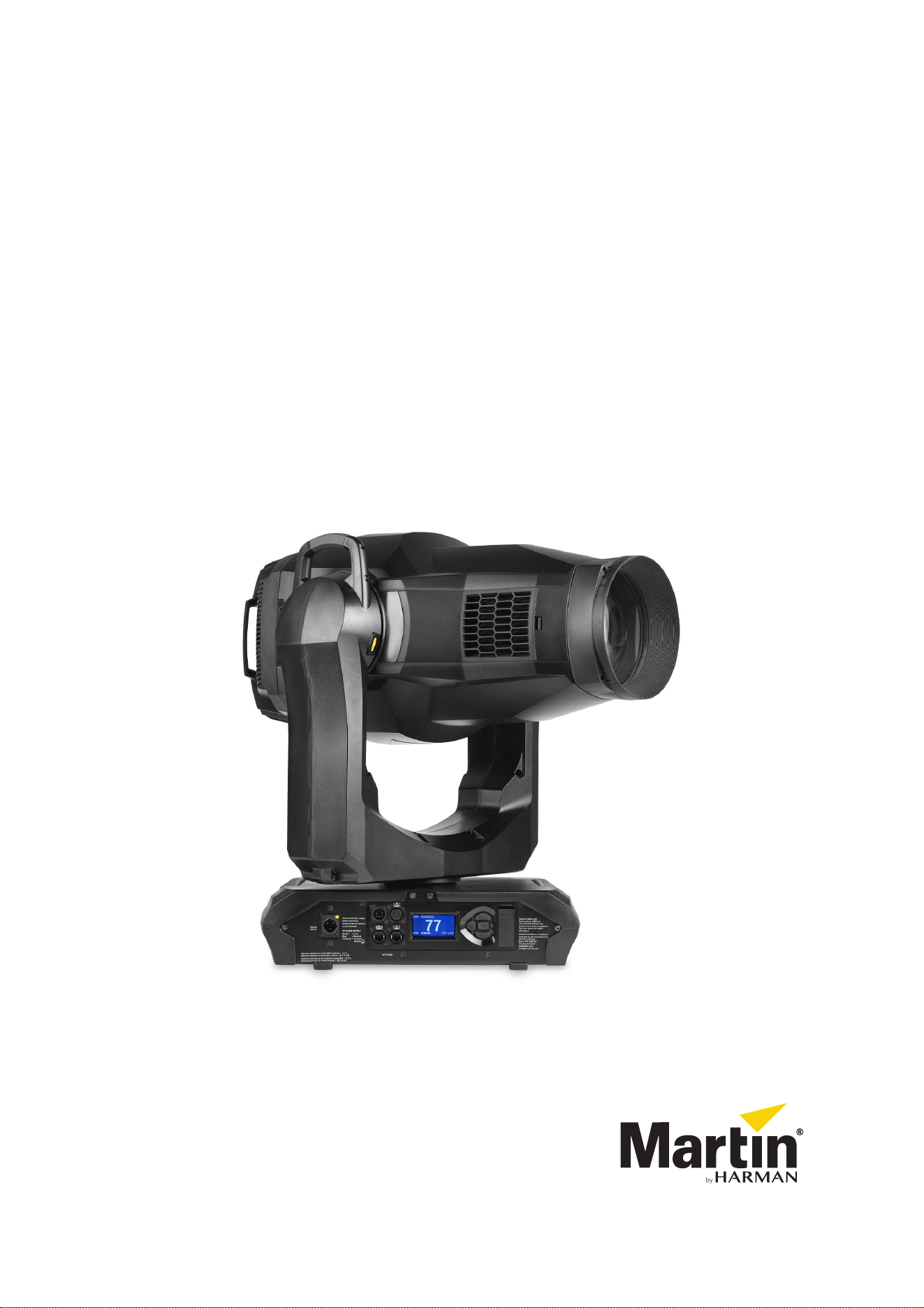
MAC Ultra Performance
Safety and Installation Manual
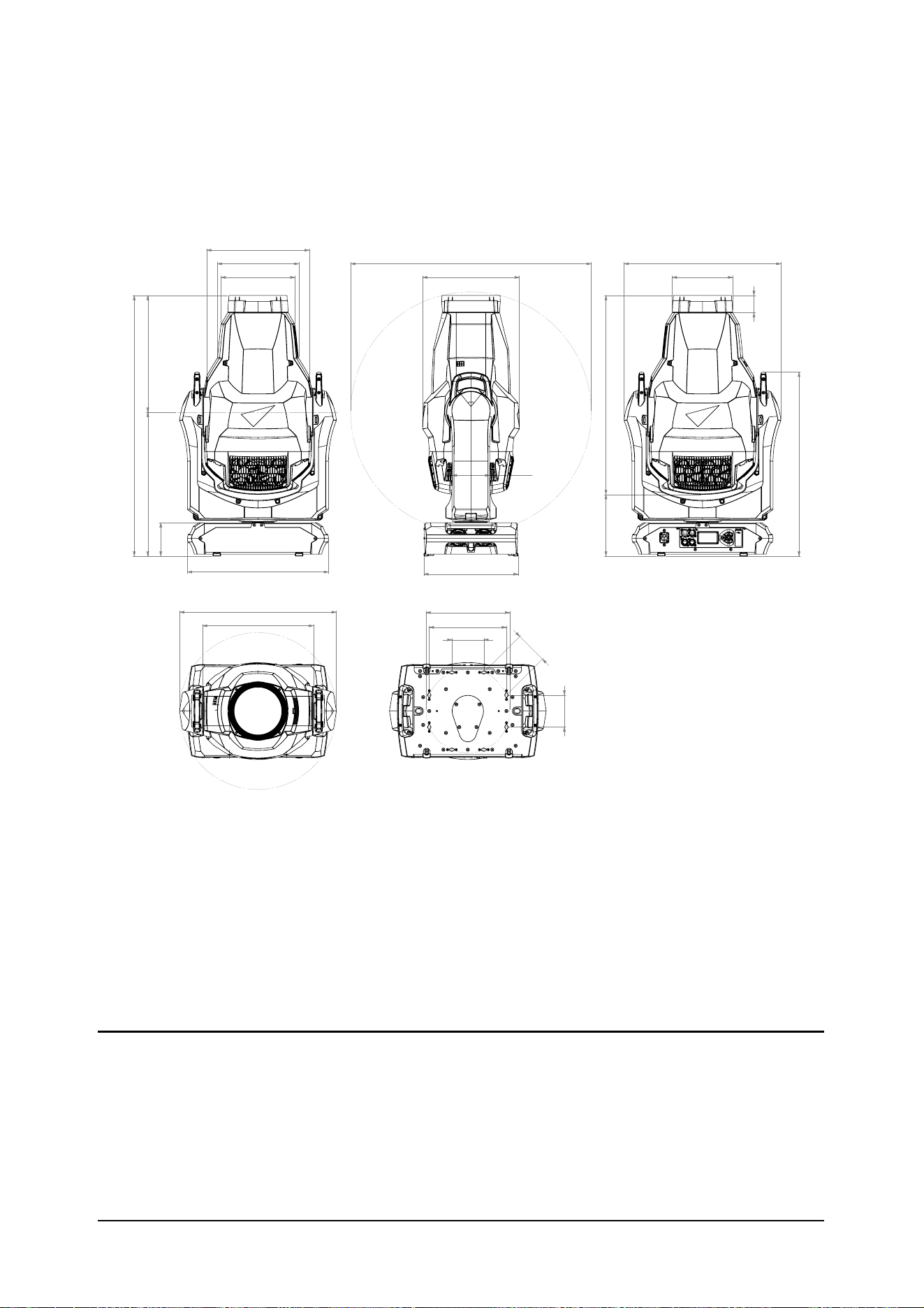
Dimensions
All measurements are given in millimeters
WLOWD[LV
WLOWGLDPHWHU
LQVLGH\RNH
SDQGLDPHWHU
©2020-2023 HARMAN PROFESSIONAL DENMARK ApS. All rights reserved. Features, specifications and appearance are subject
to change without notice. HARMAN PROFESSIONAL DENMARK ApS and all affiliated companies disclaim liability for any injury,
damage, direct or indirect loss, consequential or economic loss or any other loss occasioned by the use of, inability to use or reliance
on the information contained in this document. Martin is a registered trademark of HARMAN PROFESSIONAL DENMARK ApS
registered in the United States and/or other countries.
HARMAN PROFESSIONAL DENMARK ApS
, Olof Palmes Allé 44, 8200 Aarhus N, Denmark
HARMAN PROFESSIONAL SOLUTIONS U.S.
, 8500 Balboa Blvd., Northridge CA 91329, USA
www.martin.com
MAC Ultra Performance Safety and Installation Manual (English) Rev. A

Contents
Safety Information . . . . . . . . . . . . . . . . . . . . . . . . . . . . . . . . . . . . . . . . . . . . . . . . . . . . . . . . . . . . . . . . . . . . . 4
Introduction . . . . . . . . . . . . . . . . . . . . . . . . . . . . . . . . . . . . . . . . . . . . . . . . . . . . . . . . . . . . . . . . . . . . . . . . . . 8
Unpacking . . . . . . . . . . . . . . . . . . . . . . . . . . . . . . . . . . . . . . . . . . . . . . . . . . . . . . . . . . . . . . . . . . . . . . . . 8
Packing . . . . . . . . . . . . . . . . . . . . . . . . . . . . . . . . . . . . . . . . . . . . . . . . . . . . . . . . . . . . . . . . . . . . . . . . . . 8
Physical installation . . . . . . . . . . . . . . . . . . . . . . . . . . . . . . . . . . . . . . . . . . . . . . . . . . . . . . . . . . . . . . . . . . . . 9
Installation safety. . . . . . . . . . . . . . . . . . . . . . . . . . . . . . . . . . . . . . . . . . . . . . . . . . . . . . . . . . . . . . . . . . . 9
Installation options. . . . . . . . . . . . . . . . . . . . . . . . . . . . . . . . . . . . . . . . . . . . . . . . . . . . . . . . . . . . . . . . . . 9
AC power. . . . . . . . . . . . . . . . . . . . . . . . . . . . . . . . . . . . . . . . . . . . . . . . . . . . . . . . . . . . . . . . . . . . . . . . . . . 12
Electrical safety . . . . . . . . . . . . . . . . . . . . . . . . . . . . . . . . . . . . . . . . . . . . . . . . . . . . . . . . . . . . . . . . . . . 12
Power input . . . . . . . . . . . . . . . . . . . . . . . . . . . . . . . . . . . . . . . . . . . . . . . . . . . . . . . . . . . . . . . . . . . . . . 12
Data links. . . . . . . . . . . . . . . . . . . . . . . . . . . . . . . . . . . . . . . . . . . . . . . . . . . . . . . . . . . . . . . . . . . . . . . . . . . 14
Data via DMX cable. . . . . . . . . . . . . . . . . . . . . . . . . . . . . . . . . . . . . . . . . . . . . . . . . . . . . . . . . . . . . . . . 14
Data via Ethernet cable . . . . . . . . . . . . . . . . . . . . . . . . . . . . . . . . . . . . . . . . . . . . . . . . . . . . . . . . . . . . . 15
Service and maintenance . . . . . . . . . . . . . . . . . . . . . . . . . . . . . . . . . . . . . . . . . . . . . . . . . . . . . . . . . . . . . . 16
Tilt lock. . . . . . . . . . . . . . . . . . . . . . . . . . . . . . . . . . . . . . . . . . . . . . . . . . . . . . . . . . . . . . . . . . . . . . . . . . 16
Cleaning. . . . . . . . . . . . . . . . . . . . . . . . . . . . . . . . . . . . . . . . . . . . . . . . . . . . . . . . . . . . . . . . . . . . . . . . . 17
Battery replacement. . . . . . . . . . . . . . . . . . . . . . . . . . . . . . . . . . . . . . . . . . . . . . . . . . . . . . . . . . . . . . . . 17
Head air filter . . . . . . . . . . . . . . . . . . . . . . . . . . . . . . . . . . . . . . . . . . . . . . . . . . . . . . . . . . . . . . . . . . . . . 18
Lubrication . . . . . . . . . . . . . . . . . . . . . . . . . . . . . . . . . . . . . . . . . . . . . . . . . . . . . . . . . . . . . . . . . . . . . . . 19
Service utilities. . . . . . . . . . . . . . . . . . . . . . . . . . . . . . . . . . . . . . . . . . . . . . . . . . . . . . . . . . . . . . . . . . . . 19
Calibration . . . . . . . . . . . . . . . . . . . . . . . . . . . . . . . . . . . . . . . . . . . . . . . . . . . . . . . . . . . . . . . . . . . . . . . 19
Installing firmware . . . . . . . . . . . . . . . . . . . . . . . . . . . . . . . . . . . . . . . . . . . . . . . . . . . . . . . . . . . . . . . . . 20
Opening the head for access. . . . . . . . . . . . . . . . . . . . . . . . . . . . . . . . . . . . . . . . . . . . . . . . . . . . . . . . . 21
Rotating gobo replacement . . . . . . . . . . . . . . . . . . . . . . . . . . . . . . . . . . . . . . . . . . . . . . . . . . . . . . . . . . 22
Replacing the prism with a frost filter. . . . . . . . . . . . . . . . . . . . . . . . . . . . . . . . . . . . . . . . . . . . . . . . . . . 28
Replacing the standard frost with a heavy frost filter. . . . . . . . . . . . . . . . . . . . . . . . . . . . . . . . . . . . . . . 30
Using the fixture . . . . . . . . . . . . . . . . . . . . . . . . . . . . . . . . . . . . . . . . . . . . . . . . . . . . . . . . . . . . . . . . . . . . . 32
Battery power. . . . . . . . . . . . . . . . . . . . . . . . . . . . . . . . . . . . . . . . . . . . . . . . . . . . . . . . . . . . . . . . . . . . . 32
Troubleshooting . . . . . . . . . . . . . . . . . . . . . . . . . . . . . . . . . . . . . . . . . . . . . . . . . . . . . . . . . . . . . . . . . . . . . 33
Compliance and legal . . . . . . . . . . . . . . . . . . . . . . . . . . . . . . . . . . . . . . . . . . . . . . . . . . . . . . . . . . . . . . . . . 33
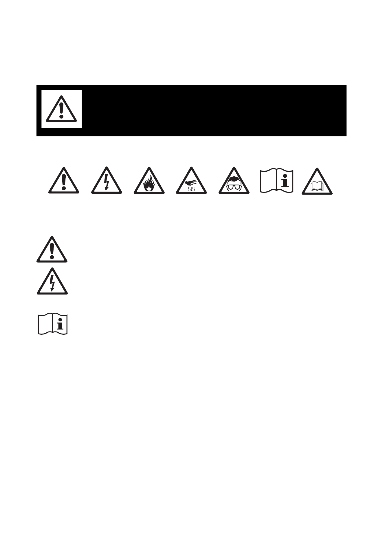
4
MAC Ultra Performance Safety and Installation Manual
Safety Information
The following symbols are used to identify important safety information on the product and in this document:
Warning! The MAC Ultra Performance from Martin® contains components that are accessible and
live at high voltage while the fixture is connected to power. These components remain under
tension for up to five minutes after power is disconnected.
Warning! Risk Group 3 product according to EN 62471 and Risk Group 2 product according to
IEC/TR 62778 (see “Protection from eye injury” on page 6 for full details). This product produces
intense light output that may be hazardous if suitable precautions are not taken. Do not view the
light output with optical instruments or any device that may concentrate the beam.
This product presents risks of severe injury or death due to fire and burn hazards, electric shock and falls if
the safety precautions in this manual are not followed.
Read this manual before installing, powering or servicing the fixture. Follow the safety precautions and
observe all warnings in this manual, in the MAC Ultra Performance User Guide and printed on the fixture.
The latest versions of this Safety and Installation Manual and the MAC Ultra Performance User Guide are
available for download from the MAC Ultra Performance areas of the Martin website at www.martin.com.
Before you install, operate or service the fixture, check the Martin website and make sure that you have the
latest user documentation for the fixture. Document revisions are indicated at the bottom of page 2.
The MAC Ultra Performance is for professional use as a stage light only. It is not for household or general
lighting applications. Respect all locally applicable laws, codes and regulations when installing, powering,
operating or servicing the fixture.
Install, operate and service Martin products and accessories only as directed in their user documentation,
or you may create a safety hazard or cause damage that is not covered by product warranties.
The latest software, manuals and other documentation for all Martin products are available for download at
www.martin.com
Technical Support
If you have questions about how to install or operate the fixture safely, please contact Harman Professional
Technical support:
• For technical support in North America, please contact: HProTechSupportUSA@harman.com
Phone: (844) 776-4899
• For technical support outside North America, please contact your national distributor.
WARNING!
Read the safety precautions in this section before
installing, powering, operating or servicing this
product.
DANGER!
Safety hazard.
Risk of severe
injury or death.
DANGER!
Hazardous
voltage. Risk of
lethal or severe
electric shock.
WARNING!
Fire hazard.
WARNING!
Burn hazard. Hot
surface. Do not
touch.
WARNING!
Intense light
emission.
WARNING!
Refer to user documentation.
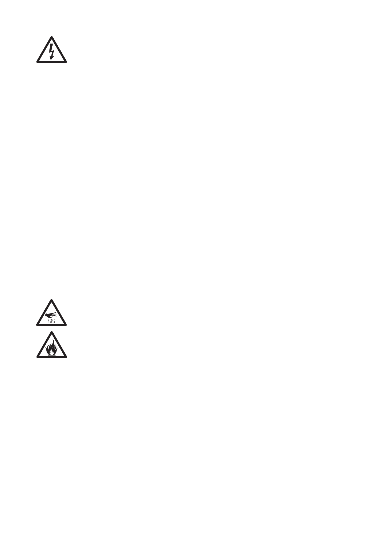
Safety Information
5
PROTECTION FROM ELECTRIC SHOCK
• The fixture has an ingress protection rating of IP20 and is for use in dry locations only. Do not expose it to
rain or moisture.
• Do not remove any cover from the fixture except as described under “Service and maintenance” on
page 16.
• Disconnect the fixture from AC mains power before servicing it and when it is not in use.
• Ensure that the fixture is electrically connected to ground (earth).
• Use only a source of AC mains power that complies with local building and electrical codes and has both
overload and ground-fault (earth-fault) protection.
• The fixture accepts AC mains power at 200-240 VAC (nominal), 50/60 Hz. Do not connect the fixture to
mains power that is not within this range.
• The power input cable must be 14 AWG or 1.5 mm
2
minimum conductor size and heat-resistant to 90° C
(194° F) minimum. Cables must have three conductors and an outer cable diameter of 6 - 12 mm (0.24 -
0.47 in.). In North America the cable must be UL/CSA-recognized, hard usage, type SJT, SJOOW or
better. In the EU, the cable must be type HO5VV-F, H07RN-F or better.
• Connect only a Neutrik powerCON TRUE1 NAC3FX-W (TOP) type cable connector to the power input
socket.
• Before using the fixture, check that all power distribution equipment, connectors and cables are in perfect
condition and rated for the current requirements of all connected devices.
• Isolate the fixture from power immediately if the power plug or any seal, cover, cable, or other component
is damaged, defective, deformed, wet or showing signs of overheating. Do not reapply power until repairs
have been completed.
• The DMX and Ethernet transceivers of the fixture are isolated/SELV to prevent ground loops and for
safety reasons.
• The fixture contains components that are accessible and live at high voltage while the fixture is connected
to power and that remain under tension for up to five minutes after power is disconnected. Wait for at least
five minutes after disconnecting from power before opening any of the fixture’s covers.
• Refer any service operation not described in this manual or in the MAC Ultra Performance User Guide to
Martin Service or an authorized Martin Service partner.
• The light source contained in this fixture shall be replaced by Martin Service or an authorized Martin
Service partner only.
• Do not use this equipment at an altitude of more than 2000 m (6570 ft.) above sea level.
PROTECTION FROM BURNS AND FIRE
• The exterior of the fixture becomes hot during use. After 5 minutes of operation a surface temperature of
85° C (185° F) shall be expected. The maximum steady state surface temperature is also 85° C (185° F).
Avoid contact by persons and materials.
• Allow the fixture to cool for at least 30 minutes before handling.
• Keep all combustible materials (e.g. fabric, wood, paper) at least 0.2 m (8 in.) away from the fixture.
• Keep flammable materials well away from the fixture.
• Ensure that there is free and unobstructed airflow around the fixture.
• Provide a minimum clearance of 0.2 m (8 in.) around fans and air vents.
• Do not illuminate surfaces within 4.75 m (15.6 ft.) of the fixture.
• Do not expose the front lens to sunlight or any other strong light source from any angle. Lenses can focus
the sun's rays inside the fixture, creating a potential fire hazard.
• Do not attempt to bypass thermostatic switches or fuses.
• Do not operate the fixture if the ambient temperature (Ta) exceeds 40° C (104° F).
• Do not modify the fixture in any way not described in this manual or the fixture’s User Guide or install other
than genuine Martin parts. Do not stick filters, masks or other materials onto any lens or other optical
component. Use only accessories approved by Martin to mask or modify the light beam.
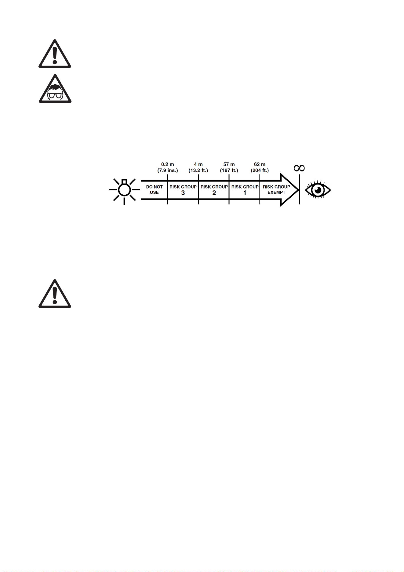
6
MAC Ultra Performance Safety and Installation Manual
PROTECTION FROM EYE INJURY
• Do not stare at the light source.
• Do not look at LEDs with magnifiers, telescopes, binoculars or similar optical instruments that may
concentrate the light output.
• Ensure that persons are not looking at the fixture when the fixture lights up suddenly. This can happen
when power is applied, when the fixture receives a DMX signal, or when certain control menu items are
selected.
• Disconnect the fixture from power at all times when the fixture is not in use.
• Provide well-lit conditions to reduce the pupil diameter of anyone working on or near the fixture.
• This fixture corresponds to Risk Group 3 according to EN 62471 when all photobiological risks are
considered and Risk Group 2 according to IEC/TR 62778 for blue light only. It emits possibly hazardous
optical radiation.
• The fixture falls into the Risk Group categories shown below according to both EN 62471 and IEC/TR
62778 under worst-case conditions:
• At a distance of less than 4 m (13.2 ft.) from the fixture, the light output can potentially cause eye or skin
injury before an exposed person's natural aversion responses (blink reflex and reaction to skin discomfort)
can protect them. At distances greater than 4 m (13.2 ft.), potential eye and skin injury hazards from the
light output are normally prevented by natural aversion reflexes.
• Position the fixture so that persons cannot be exposed to the fixture's light output at a distance of less
than 4 m (13.2 ft.) from the fixture, and so that prolonged staring into the light output at less than 57 m
(187 ft.) from the fixture is not expected.
PROTECTION FROM INJURY
• Fasten the fixture securely to a fixed surface or structure when in use. The fixture is not portable when
installed.
• Do not lift or carry the fixture alone.
• Apply the tilt lock and use the handles on the base and on the yoke when carrying the fixture.
• The handles on the back of the head are designed for use by a followspot operator only. Do not use them
to carry the fixture.
• Use two evenly spaced omega brackets with clamps to suspend the fixture from rigging structures. Do not
use only one clamp.
• When clamping the fixture to a truss or other supporting structure, use two half-coupler clamps. Do not
use G-clamps, quick-trigger clamps or any other type of clamp that does not completely encircle the
supporting structure when fastened.
• The fixture weighs 44 kg (97.1 lbs.). When suspending the fixture, check that the supporting structure and
all hardware used to suspend the fixture can hold at least six (6) times the weight of all devices
suspended from them and that the installation respects all similar safety factors that are required by
locally applicable regulations. Check that the structure and hardware are in perfect condition and suitable
for their purpose.
• If the fixture is installed in a location where it may cause injury or damage if it falls, install as described in
this manual a secondary attachment such as a safety cable that is approved by an official body such as
TÜV as a safety attachment for the weight that it secures. The safety cable must comply with
EN/IEC 60598-2-17:2018 Section 17.7.4 or BGV C1 / DGUV 17, and must be capable of bearing a static
suspended load at least six times (or more if required by locally applicable regulations) the weight that it
secures.
• Eliminate as much slack as possible in the safety cable (by looping it more than once around the rigging
truss, for example). Make sure that, if the primary attachment fails, the fixture cannot fall more than 20 cm
(8 inches) maximum before the safety cable catches it.
• If the safety cable attachment point becomes deformed, do not suspend the fixture. Have the fixture
repaired by an authorized Martin service partner.
• Check that all external covers and rigging hardware are securely fastened.

Safety Information
7
• Block access below the work area and work from a stable platform whenever installing, servicing or
moving the fixture.
• Allow enough clearance around the head to ensure that it cannot collide with a person or object such as
another fixture when it moves.
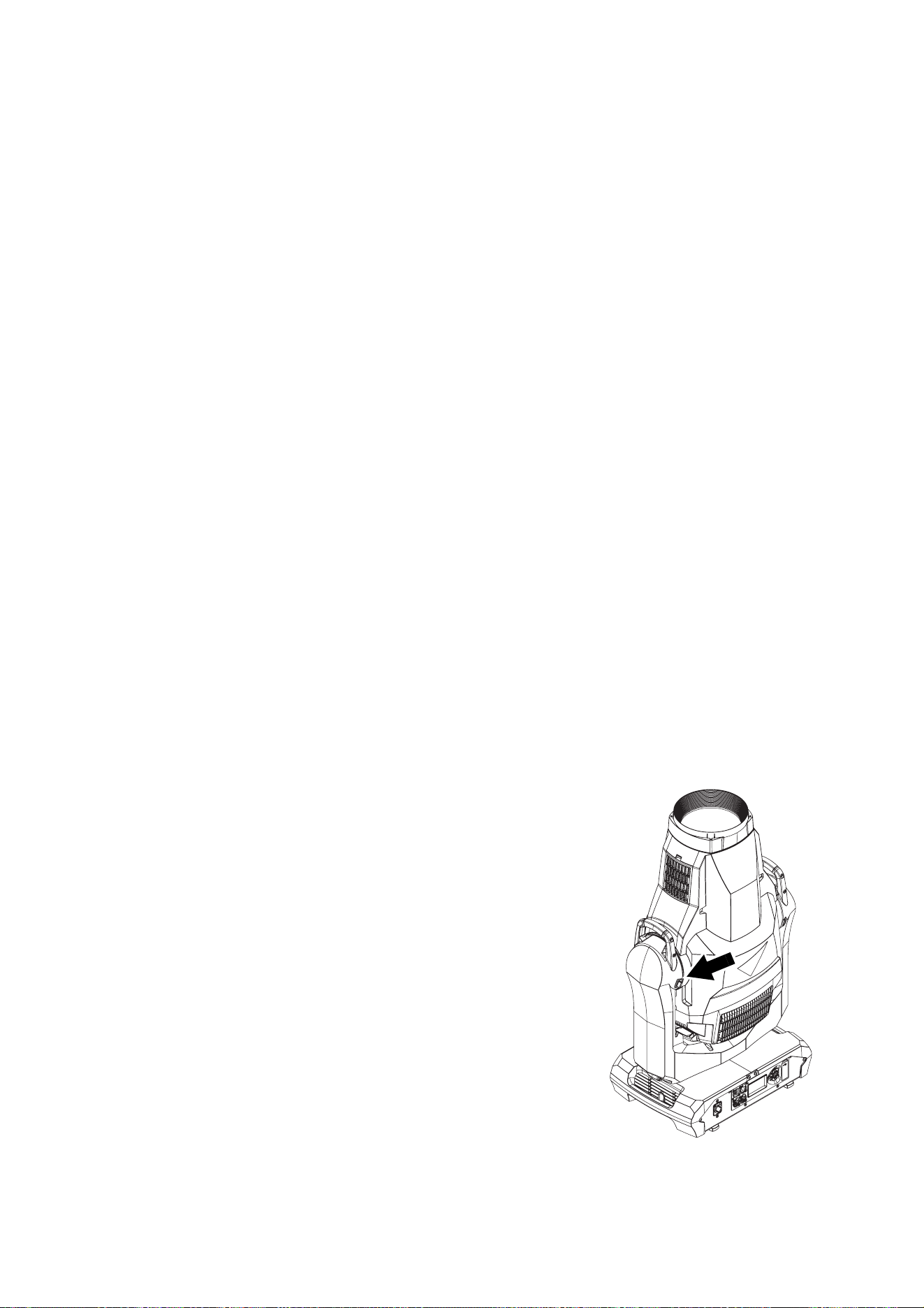
8
MAC Ultra Performance Safety and Installation Manual
Introduction
Thank you for selecting the MAC Ultra Performance lighting fixture from Martin®.
This Safety and Installation Manual is supplied with the fixture. It gives details of installing and servicing the
fixture. The MAC Ultra Performance User Guide, containing full instructions to help you set up, control and
monitor the fixture, is available for download from the MAC Ultra Performance area of the Martin website at
www.martin.com. If you have any difficulty locating this document, please contact your Martin supplier for
assistance. The MAC Ultra Performance area of the Martin website also contains full product specifications
and information to help you order accessories such as cables, flightcases etc.
Before installing, operating or servicing the MAC Ultra Performance, please check the fixture’s area of the
Martin website at www.martin.com and make sure that you have the latest user documentation for the
product.
Product specifications are not included in the fixture’s user documentation. You can find full specifications
for the fixture in the MAC Ultra Performance area of the Martin website.
Unpacking
The MAC Ultra Performance is supplied in a SIP insert that is intended for use in the Martin MAC Ultra
series flightcase. The fixture and SIP insert are supplied in a cardboard box that is designed to protect the
fixture during initial shipment only. We strongly recommend that you store and transport fixtures in the
rugged flightcases available from Martin (or custom flightcases of the same quality) using the SIP insert
supplied with the fixture. The Martin flightcase holds two fixtures.
See the MAC Ultra Performance area of the Martin website at www.martin.com for details of flightcases and
other accessories available for this fixture.
Avoiding condensation
If you move the fixture from a cold to a warm environment, remove it from its flightcase or packaging and
give it at least two hours to acclimatise before you apply power. This will help to avoid damage due to
condensation.
Tilt lock
Check that the tilt lock is released before applying power to the
fixture.
See Figure 1. To release the tilt lock, slide the tilt lock button
(arrowed) to the Unlocked position. To reapply the tilt lock, first
check that the power is off and then slide the tilt lock button
back to the Locked position.
Release the tilt lock before putting the fixture into its SIP insert
and flightcase or cardboard box for transport or storage.
Packing
Important! Allow the fixture to cool for 30 minutes and release the tilt
lock before packing it for storage or transport.
The SIP insert supplied with the fixture is designed to support
the head with the tilt lock in the Unlocked position. Release the
tilt lock before putting a fixture into its SIP insert in a flightcase
or cardboard box. Leaving the tilt lock applied may cause
damage that is not covered by the product warranty when the
fixture is moved.
Figure 1: Tilt lock
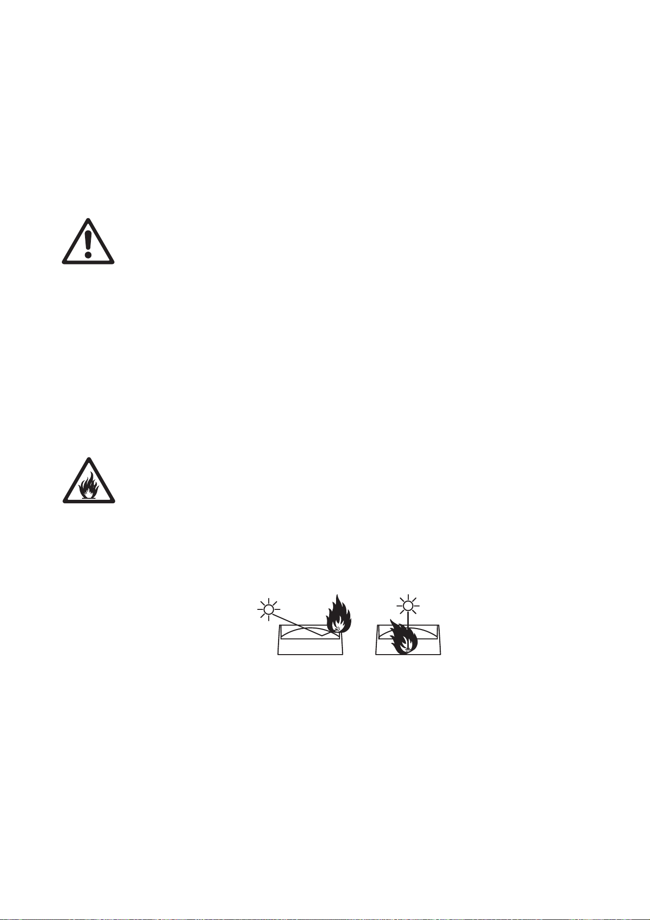
Physical installation
9
Physical installation
Installation safety
The fixture weighs 44 kg (97.1 lbs.), not including installation hardware.
See “Dimensions” on page 2 for details of the fixture’s physical dimensions.
Warning! The MAC Ultra Performance has a powerful pan motor. The torque reaction when the head
is panned suddenly can cause the base to move if the fixture is standing unsecured on a surface.
Do not apply power to the MAC Ultra Performance unless the base is securely fastened to a stable
surface or structure.
Warning! Use two evenly spaced rigging clamps to rig the fixture. Do not hang the fixture from only
one clamp. Lock omega brackets to the base of the fixture with both 1/4-turn fasteners. Fasteners
are locked only when turned a full 90° clockwise.
Warning! When suspending the fixture above ground level, secure it against failure of primary
attachments by attaching a safety cable that is approved as a safety attachment for the weight of the
fixture to the attachment point in the base. Do not use the carrying handles for secondary
attachment.
Warning! When clamping the fixture to a truss or other structure at any other angle than with the
yoke hanging vertically downwards, use two clamps of half-coupler type. Do not use any type of
clamp that does not completely encircle the structure when fastened.
Warning! To avoid head collisions when installing MAC Ultra Performance fixtures beside each
other, allow a minimum center-to-center distance between fixtures of 830 mm (32.7 in.). The fixture
also contains a programmable pan/tilt limitation system that allows you to limit head movement
where necessary in order to prevent head collisions. See the MAC Ultra Performance User Guide for
details.
Warning! You can fasten the fixture to a surface with ratchet straps passed through the carrying
handles in the base so that the fixture cannot fall over, but do not over-tighten the ratchet straps or
you may damage the carrying handles and leave the fixture in an unsafe condition.
Warning! See Figure 2. The MAC Ultra Performance’s lens can focus sunlight and strong artificial
light, creating a potential fire hazard and causing damage that is not covered by the product
warranty. Position or shade the head so that the front lens will not be exposed to sunlight or another
strong light source from any angle – even for a few seconds.
Important! Powerful light can damage the control panel display. Do not point the output from other
lighting fixtures at the MAC Ultra Performance.
Installation options
The MAC Ultra Performance can be fastened to a surface such as a stage or clamped to a truss in any
orientation using two omega brackets (see Figure 4) and rigging clamps. Clamps must be half-coupler type
(see Figure 4) or equivalent type that fully encircles the truss unless the fixture is installed with the yoke
hanging vertically downwards, in which case other clamp types that are approved for the supported weight
may be used.
Figure 2: Potential sunlight damage
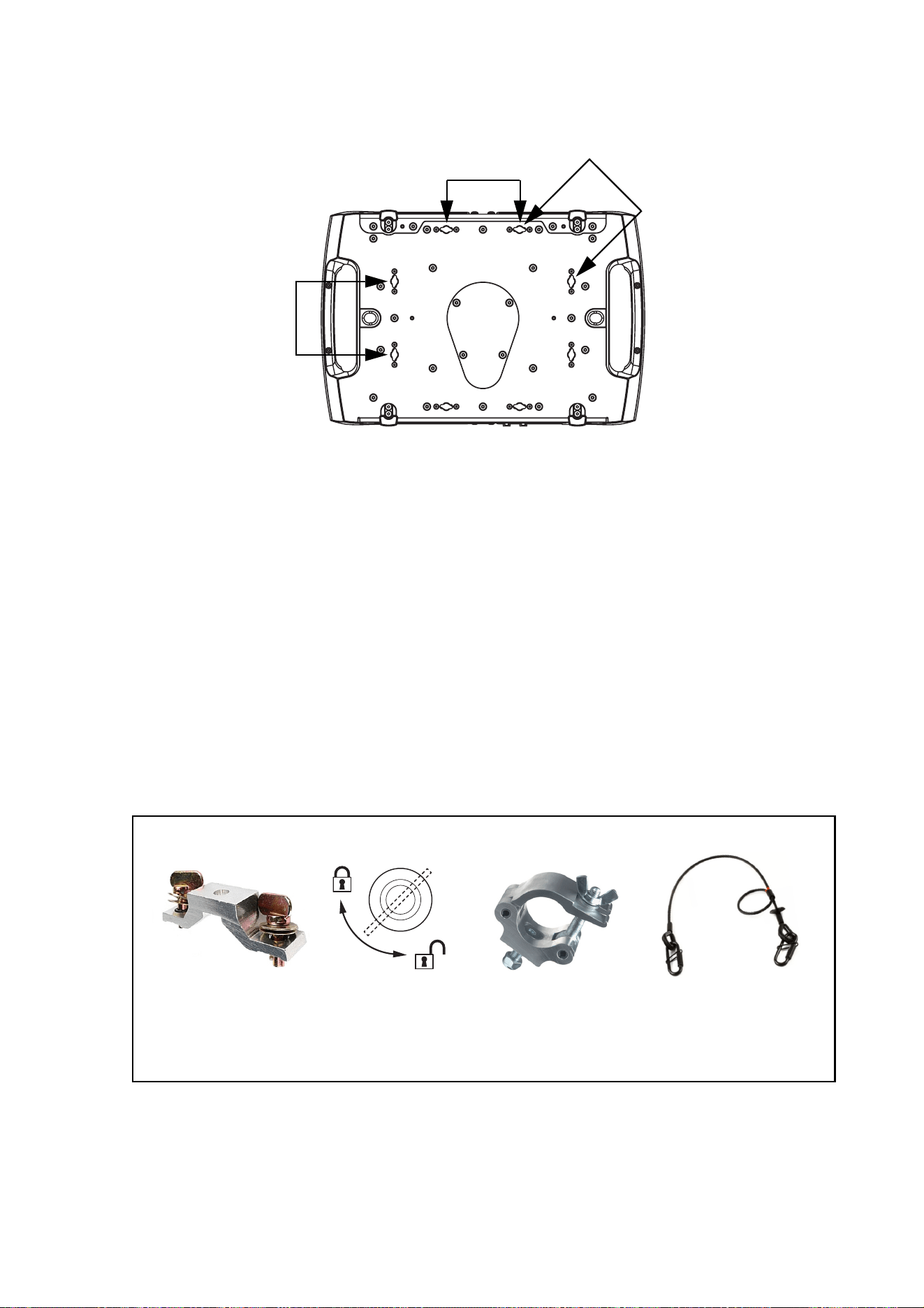
10
MAC Ultra Performance Safety and Installation Manual
The four pairs of quarter-turn mounting points in the base accept 106 mm (4.17 in.) center-to-center omega
brackets (see Figure 4) for rigging clamp attachment. The omega brackets can be fastened to the base
parallel to the fixture’s sides or diagonally (see Figure 3).
Installation hardware
Two omega brackets suitable for use when rigging the MAC Ultra Performance are supplied with the fixture.
Martin can supply as accessories suitable rigging clamps and safety cables that are approved for the weight
of the fixture. Contact your Martin supplier for details.
Clamping the fixture to a truss
To clamp the MAC Ultra Performance to a rigging truss:
1. Check that all rigging hardware is undamaged and can bear at least six (6) times the weight of the fixture
or as required by locally applicable regulations. Check that the supporting structure can safely bear the
weight of all installed fixtures, clamps, cables, auxiliary equipment, etc. and complies with locally
applicable regulations.
2. Bolt two rigging clamps securely to omega brackets using M12 bolts (minimum grade 8.8) and
self-locking nuts.
Figure 3: Omega bracket mounting points
106
106
106
Safety cable,
60 kg SWL, black
P/N 91604006
Figure 4: Martin rigging hardware
Half-couplerOmega bracket for
rigging clamp,rigging clamp attachment
90°
Locking quarter-
turn fasteners
P/N 91602005
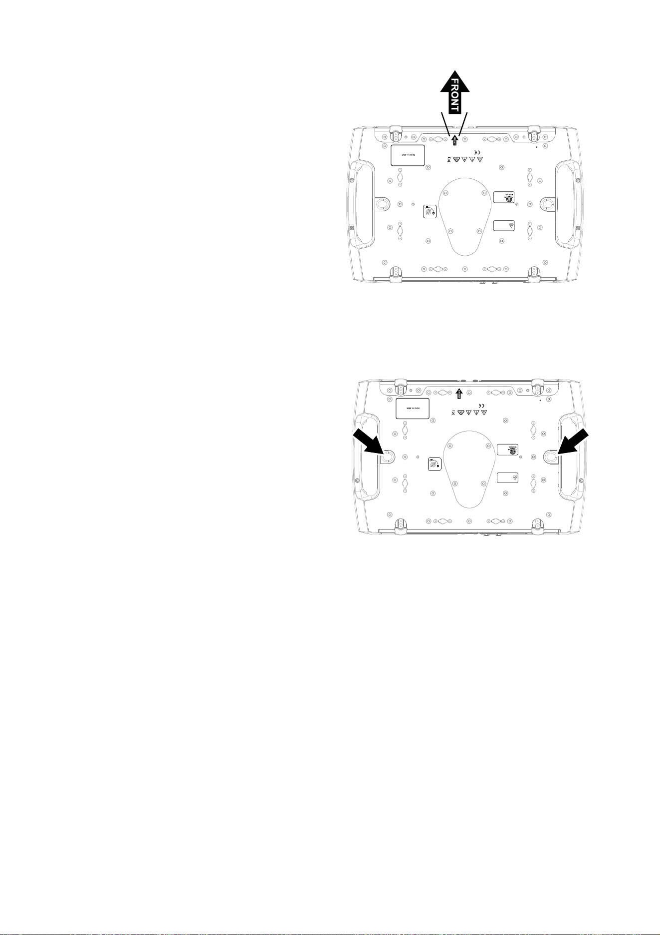
Physical installation
11
3. See Figure 3 on page 10. Align the first
clamp and bracket with 2 mounting
points in the base, and engage both the
clamp bracket’s quarter-turn fasteners in
corresponding sockets in the base. See
Figure 4. Turn the levers on the
quarter-turn fasteners a full 90°
clockwise to lock.
4. Repeat for the second clamp, installing it
opposite the first so that the fixture will
be held in balance.
5. Block access under the work area. See
Figure 5. Note the position of the arrow
marked FRONT on the base of the
fixture. Working from a stable platform,
hang the fixture on the rigging truss with
the arrow marked FRONT facing
towards the area to be illuminated.
Tighten the rigging clamps.
6. See Figure 6. Install a safety cable that is
approved as a safety attachment for the
weight of the fixture by looping it through
one of the safety cable attachment points
(arrowed) in the bottom of the base and
around a secure anchoring point so that
the safety cable will catch the fixture if a
primary attachment fails. Remove as
much slack as possible from the safety
cable (by looping it more than once
around the truss, for example).
7. Check that the tilt lock is released. Check
that there are no combustible materials
within 0.2 m (8 in.) or surfaces to be
illuminated within 4.75 m (15.6 ft.) of the
fixture, and that there are no flammable
materials nearby.
8. Check that there is no possibility of the
head colliding with objects or other
fixtures.
9. Check that other lighting fixtures cannot project light at the MAC Ultra Performance, as powerful
illumination can damage the fixture’s display.
Figure 5: Front of fixture
ATTENTION!
• Pour consignes de sécurité voir guide de l’utilisateur.
• Avant la mise sous tension, vérifier que l'appareil accepte
la tension et la fréquence d'alimentation.
• Confier la maintenance à un personnel qualifié.
• Température ambiante maximum d’utilisation T
a
= 40°C.
• Emplacements secs.
• Risque de feu et de choc électrique.
• Ne convient pas à l’usage domestique.
• Ne pas regarder directement dans la source lumineuse.
HARMAN Professional Denmark ApS
Olof Palmes Allé 44
8200 Aarhus N, Denmark
Covered by one or more intellectual property rights, including one or
more intellectual property rights listed on www.martin.com/ipr
and design 2019 Martin Professional ApS
SAFETY CABLE
WARNING!
• Lock bracket with both 1/4 turn fasteners.
• Turn 1/4 fasteners fully clockwise to lock.
• Use 2 clamps to mount fixture.
• Secure fixture with safety cable when
suspending.
1/4 turn fasteners
CW
CCW
ATTENTION!
• Verrouiller les crochets avec les
deux 1/4 de tour.
• Verrouiller les 1/4 de tour en tournant à
fond dans le sens des aiguilles d'une montre.
• Utiliser deux crochets pour monter la machine.
• Installer une élingue de sécurité.
SAFETY CABLE
WARNING!
• For safety instructions see user guide.
• Before operation ensure that voltage and frequency
match local power supply.
• Refer servicing to qualified service personnel.
• Maximum ambient temperature T
a
= 40°C.
• Use only in dry locations.
• Risk of fire and electric shock.
• Not for residential/household use.
• Do not look directly into the light.
This device complies with part 15 of the FCC Rules.
Operation is subject to the following two conditions:
(1) This device may not cause harmful interference, and
(2) this device must accept any interference received,
including interference that may cause undesired operation.
CAN ICES-3 (B) / NMB-3 (B); CAN ICES-5 (B) / NMB-5 (B)
5002071
Conforms to
UL Std. 1573
Certified to
CSA Std.
C22.2 No. 166
See user guide for
photobiological
safety information.
Voir le guide de l’utilisateur
pour plus d’information sur la
sécurité photobiologique.
Figure 6: Safety cable attachment points
ATTENTION!
• Pour consignes de sécurité voir guide de l’utilisateur.
• Avant la mise sous tension, vérifier que l'appareil accepte
la tension et la fréquence d'alimentation.
• Confier la maintenance à un personnel qualifié.
• Température ambiante maximum d’utilisation T
a
= 40°C.
• Emplacements secs.
• Risque de feu et de choc électrique.
• Ne convient pas à l’usage domestique.
• Ne pas regarder directement dans la source lumineuse.
HARMAN Professional Denmark ApS
Olof Palmes Allé 44
8200 Aarhus N, Denmark
Covered by one or more intellectual property rights, including one or
more intellectual property rights listed on www.martin.com/ipr
and design 2019 Martin Professional ApS
SAFETY CABLE
WARNING!
• Lock bracket with both 1/4 turn fasteners.
• Turn 1/4 fasteners fully clockwise to lock.
• Use 2 clamps to mount fixture.
• Secure fixture with safety cable when
suspending.
1/4 turn fasteners
CW
CCW
ATTENTION!
• Verrouiller les crochets avec les
deux 1/4 de tour.
• Verrouiller les 1/4 de tour en tournant à
fond dans le sens des aiguilles d'une montre.
• Utiliser deux crochets pour monter la machine.
• Installer une élingue de sécurité.
SAFETY CABLE
WARNING!
• For safety instructions see user guide.
• Before operation ensure that voltage and frequency
match local power supply.
• Refer servicing to qualified service personnel.
• Maximum ambient temperature T
a
= 40°C.
• Use only in dry locations.
• Risk of fire and electric shock.
• Not for residential/household use.
• Do not look directly into the light.
This device complies with part 15 of the FCC Rules.
Operation is subject to the following two conditions:
(1) This device may not cause harmful interference, and
(2) this device must accept any interference received,
including interference that may cause undesired operation.
CAN ICES-3 (B) / NMB-3 (B); CAN ICES-5 (B) / NMB-5 (B)
5002071
Conforms to
UL Std. 1573
Certified to
CSA Std.
C22.2 No. 166
See user guide for
photobiological
safety information.
Voir le guide de l’utilisateur
pour plus d’information sur la
sécurité photobiologique.
12
MAC Ultra Performance Safety and Installation Manual
AC power
Electrical safety
The MAC Ultra Performance features an auto-sensing switch-mode power supply that automatically adapts
to AC mains power at 200-240 VAC (nominal), 50/60 Hz. Do not connect the fixture to power that is not
within this range. Note that the fixture must not be connected to AC mains power at 100-120 V.
Maximum current draw is as follows:
• At 200 V: 8.0 A
• At 240 V: 6.7 A
Typical half-cycle RMS inrush current: 17 A at 230 V, 50 Hz.
Typical earth-leakage current: 0.59 mA.
Warning! Read “Safety Information” on page 4 before connecting the fixture to AC mains power.
For protection from electric shock, the fixture must be electrically connected to ground (earth). The
AC mains power distribution circuit must be equipped with a fuse or circuit breaker and ground-fault
(earth-fault) protection.
Power input
Important! Connect the MAC Ultra Performance directly to AC mains power. Do not connect it to a
dimmer system; doing so may damage the fixture.
The MAC Ultra Performance automatically adapts to AC mains power at 200-240 VAC (nominal), 50/60 Hz.
Connect the fixture only to AC mains power that is within this range.
The fixture requires a power input cable with a Neutrik powerCON TRUE1 NAC3FX-W (TOP) female cable
connector for AC mains power input. The cable must meet the requirements listed under “Protection from
electric shock” on page 5. Martin can supply suitable cables with female TRUE1 (TOP) input connectors
and can also supply loose connectors. The specifications on the MAC Ultra Performance page on the Martin
website at www.martin.com give details of all the suitable cables and connectors available from Martin.
Connection to an AC mains power source
When powering on, the MAC Ultra Performance will typically draw a half-cycle RMS inrush current of 17 A
for a few milliseconds at 230 V, 50 Hz. To avoid unwanted tripping, we recommend the use of MCBs
(Miniature Circuit Breakers) that are classified Type D according to IEC 60898/UL489/CSA C22.2 No. 5.
The power cable can be hard-wired to a building installation circuit or fitted with a mains plug (cord cap) to
allow connection to local AC mains power outlets.
If you install a mains plug on the power cable, install a grounding-type (earthed) plug rated minimum 16 A,
250 V (example rating: EN 60309-2 CEE 2P+E 16 A/250 VAC), following the plug manufacturer’s
instructions. Table 1 shows some possible mains power pin identification schemes; if the pins are not clearly
identified, or if you have any doubts about proper installation, consult a qualified electrician.
Wire Color (US) Wire Color (EU) Pin Symbol Screw (US)
black brown live L yellow or brass
white blue neutral N silver
green yellow/green ground (earth) or green
Table 1: Cord cap (mains plug) connections
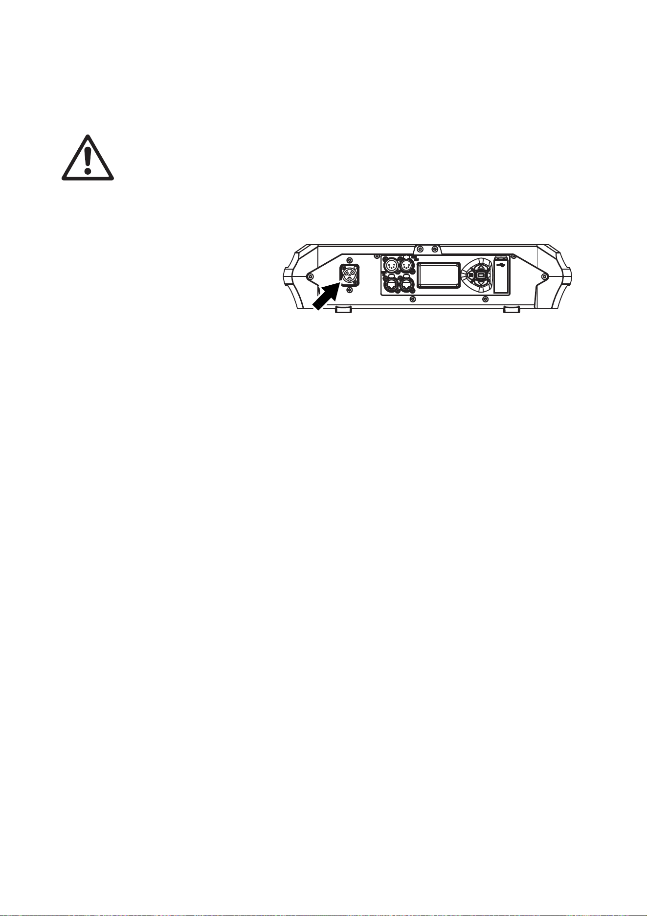
AC power
13
If you need to install a Neutrik powerCON TRUE1 (TOP) connector on a power cable, follow the instructions
on the Neutrik website at www.neutrik.com.
Applying power
Warning! The MAC Ultra Performance does not have a power On/Off switch. As soon as you connect
an energized power input cable to the fixture or apply power to a power input cable that has already
been connected, the fixture will power up: check that there is no safety risk from head movement or
intense light output.
To apply power to the MAC Ultra Performance:
1. Check that the tilt lock is released and that the base is held securely. Be prepared for the fixture to light
up and the head to move suddenly when power is applied.
2. See Figure 7. line up the keys
in the power input cable’s
TRUE1 (TOP) connector with
the keyways in the MAINS IN
socket (arrowed). Insert the
connector into the socket and
twist clockwise to engage. If
the connector seems difficult
to twist, remove it from the
socket, check that you have
lined up the keyways correctly
and try again – do not use excessive force. Make sure that the connector latch clicks and that the
connector is locked into the socket.
3. Apply power to the input cable to power the fixture on.
To disconnect the MAC Ultra Performance from power, pull the release latch on the connector towards you
to unlock the connector, twist the connector counter-clockwise, and then withdraw it from the MAINS IN
socket.
Figure 7: Mains input socket
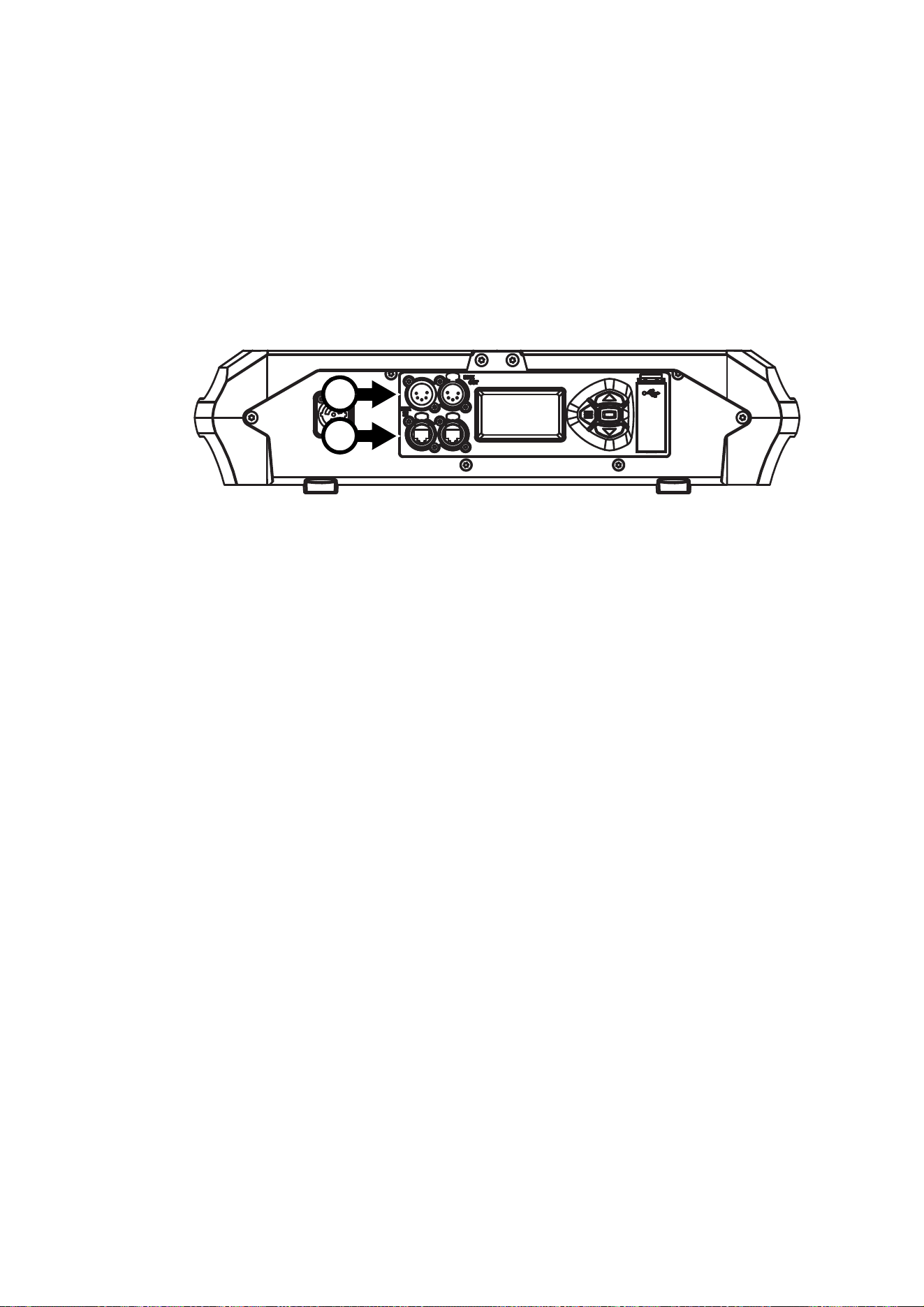
14
MAC Ultra Performance Safety and Installation Manual
Data links
Important! Shut down power to the fixture before connecting to or disconnecting from data.
The MAC Ultra Performance has two pairs of connectors for control data In/Out:
• one pair of XLR sockets (A in Figure 8), and
• one pair of etherCON sockets (B in Figure 8).
Use only one socket type – either XLR or etherCON – at any one time.
Data via DMX cable
The MAC Ultra Performance has 5-pin locking XLR sockets (see A in Figure 8) for DMX and RDM input and
output via DMX cable. The default pin-out on both sockets is:
• pin 1 to shield
• pin 2 to data 1 cold (-)
• pin 3 to data 1 hot (+).
Pins 4 and 5 are not used by the fixture but are bridged between input and output sockets. These pins can
therefore be used as a pass-through connection for an additional data signal if required.
Tips for reliable data transmission via DMX cable
• Use shielded twisted-pair high-quality DMX cable.
• 24 AWG cable is suitable for runs up to 300 meters (1000 ft). Heavier gauge cable and/or an amplifier is
recommended for longer runs.
• Do not use microphone cable, as standard microphone cable does not have the correct impedance and
cannot transmit control data reliably over long runs.
• To split the data link into branches, use an optically isolated splitter-amplifier.
• Do not overload the DMX data link. You can connect up to a maximum of 32 devices on a serial DMX link.
• Install a DMX termination plug on the last fixture on the link.
Connecting to data via DMX cable
To connect the MAC Ultra Performance to DMX and/or RDM data carried over DMX cable:
1. Shut down power to the fixture.
2. Connect the DMX data output from the controller to the MAC Ultra Performance’s data input (male XLR)
socket using good-quality DMX cable.
3. Run DMX cable from the MAC Ultra Performance’s data output (female XLR) socket to the data input of
the next fixture and continue until the link is complete.
Figure 8: Data connections
A
B

Data links
15
4. Terminate the data link by connecting a 120 Ohm, 0.25 Watt resistor between the data 1 hot (+) and cold
(-) conductors at the data output of the last fixture on the link. If the link is divided into branches using a
DMX splitter, terminate each branch of the link.
5. You can now apply power.
Data via Ethernet cable
The MAC Ultra Performance has Neutrik etherCON data sockets (see B in Figure 8) that support DMX and
RDM over Art-Net and sACN as well as Martin P3 video. Either socket can be used for input and the other
socket used for throughput.
The etherCON data sockets have a fail-safe bypass feature. This means that the fixture will relay a data
signal from the socket used for input to the socket used for throughput even if power to the fixture is shut
down or lost.
Tips for reliable data transmission via Ethernet cable
• Use shielded twisted-pair Ethernet cable of type S/UTP, SF/UTP, S/STP or SF/STP only. The cable must
be rated Cat 5e or better.
• The cable shield must be electrically connected to connector housings, and the other devices on the data
link must also support shielded connections.
• Note that the MAC Ultra Performance is compatible with 10/100 Mbit Ethernet only. Do not connect the
fixture to a network port or device that is fixed to Gigabit Ethernet speed. If you need to integrate a MAC
Ultra Performance in a Gigabit Ethernet network, use a network switch to allow the link towards the fixture
to operate at 100 Mbit/s Ethernet speed.
• To split the data link into branches, use a standard network switch that is able to operate at 100 Mbit/s
towards the fixtures.
• Even though every fixture has a fail-safe bypass mechanism and minimal latency insertion, we
recommend that you avoid connecting more than 50 devices in a single daisy-chain or branch.
• Unlike DMX cable, Ethernet cable does not require termination at the end of a daisy-chain of fixtures.
Connecting to data via Ethernet cable
To connect the MAC Ultra Performance to Art-Net, sACN or P3 video via Ethernet cable:
1. Shut down power to the fixture.
2. Connect the Ethernet cable to either of the fixture’s etherCON data sockets.
3. Run Ethernet cable from the fixture’s other etherCON data socket to a data socket on the next fixture.
4. Continue connecting data sockets as described above until the link is complete.
5. You can now apply power.
Simultaneous DMX and P3 control
To control the MAC Ultra Performance using DMX/Art-Net/sACN and P3 video at the same time, connect
the DMX/Art-Net/sACN signal to the P3 System Controller. The P3 Controller will then merge DMX
commands and video data together and send a combined data signal to fixtures over the Ethernet link using
the P3 protocol.
16
MAC Ultra Performance Safety and Installation Manual
Service and maintenance
Warning! Read “Safety Information” on page 4 before servicing the MAC Ultra Performance.
Warning! Disconnect the fixture from AC mains power and allow to cool for at least 30 minutes
before handling. Do not stare into the light output. Be prepared for the fixture to light and move
suddenly when connected to power.
Warning! The MAC Ultra Performance contains components that are accessible and live at high
voltage while the fixture is connected to power and that remain under tension for five minutes after
power is disconnected. Only qualified technicians are permitted to open the fixture. Users may carry
out external cleaning, replace the battery, replace the air filter and replace gobos as described in
this section, following the warnings and instructions provided, but any service operation not
described in this manual or in the fixture’s User Guide must be referred to an authorized Martin
service technician.
Important! Excessive dust, smoke fluid, and particle buildup degrades performance, causes
overheating and will damage the fixture. Damage caused by inadequate cleaning or maintenance is
not covered by the product warranty.
Important! Fixtures are calibrated at the factory when the light engine, CMY module and effect
module (color wheel effects module) are installed. We therefore recommend that you keep the
original modules with the fixture if you disassemble the fixture for service. If you swap modules
from one fixture to another, the fixtures may need to be recalibrated in order to maintain consistent
color characteristics across different fixtures. A small label indicating the type and serial number of
the original fixture is fixed to each module at the factory to help you keep modules together with
their original fixture.
Pressing MENU and ENTER buttons immediately when the fixture name appears in the display while
powering the fixture on puts the fixture into service mode in which pan and tilt motors are deactivated and
SERV appears in the display. To take the fixture out of service mode, power off and then power on again
normally.
The MAC Ultra Performance User Guide (available for download from the MAC Ultra Performance page on
www.martin.com) gives full details of the menus in the fixture’s control panel.
The user must clean the MAC Ultra Performance periodically to maintain optimum performance and cooling.
The user may also upload firmware (fixture software) to the fixture via the DMX data input port or USB port
using firmware and instructions from Martin. All other service operations on the MAC Ultra Performance
must be carried out by Martin, its approved service agents or trained and qualified personnel using the
official Martin service documentation for the MAC Ultra Performance.
Installation, on-site service and maintenance can be provided worldwide by the Martin Professional Global
Service organization and its approved agents, giving owners access to Martin’s expertise and product
knowledge in a partnership that will ensure the highest level of performance throughout the product’s
lifetime. Please contact your Martin supplier for details.
It is Martin policy to apply the strictest possible calibration procedures and use the best quality materials
available to ensure optimum performance and the longest possible component lifetimes. However, optical
components are subject to wear and tear over the life of the product, resulting in gradual changes in color
over many thousands of hours of use. The extent of wear and tear depends heavily on operating conditions
and environment, so it is impossible to specify precisely whether and to what extent performance will be
affected. However, you may eventually need to replace optical components if their characteristics are
affected by wear and tear after an extended period of use and if you require fixtures to perform within very
precise optical and color parameters.
Tilt lock
The tilt position of the head can be locked for service. See Figure 1 on page 8.
Important! Release the tilt lock before applying power to the fixture. Leaving the tilt lock applied during
transport can result in damage that is not covered by the product warranty. The SIP insert is
designed to protect the head from shocks during transport. Release the tilt lock before packing the
fixture in its SIP insert for transport or storage in its flightcase or cardboard box.
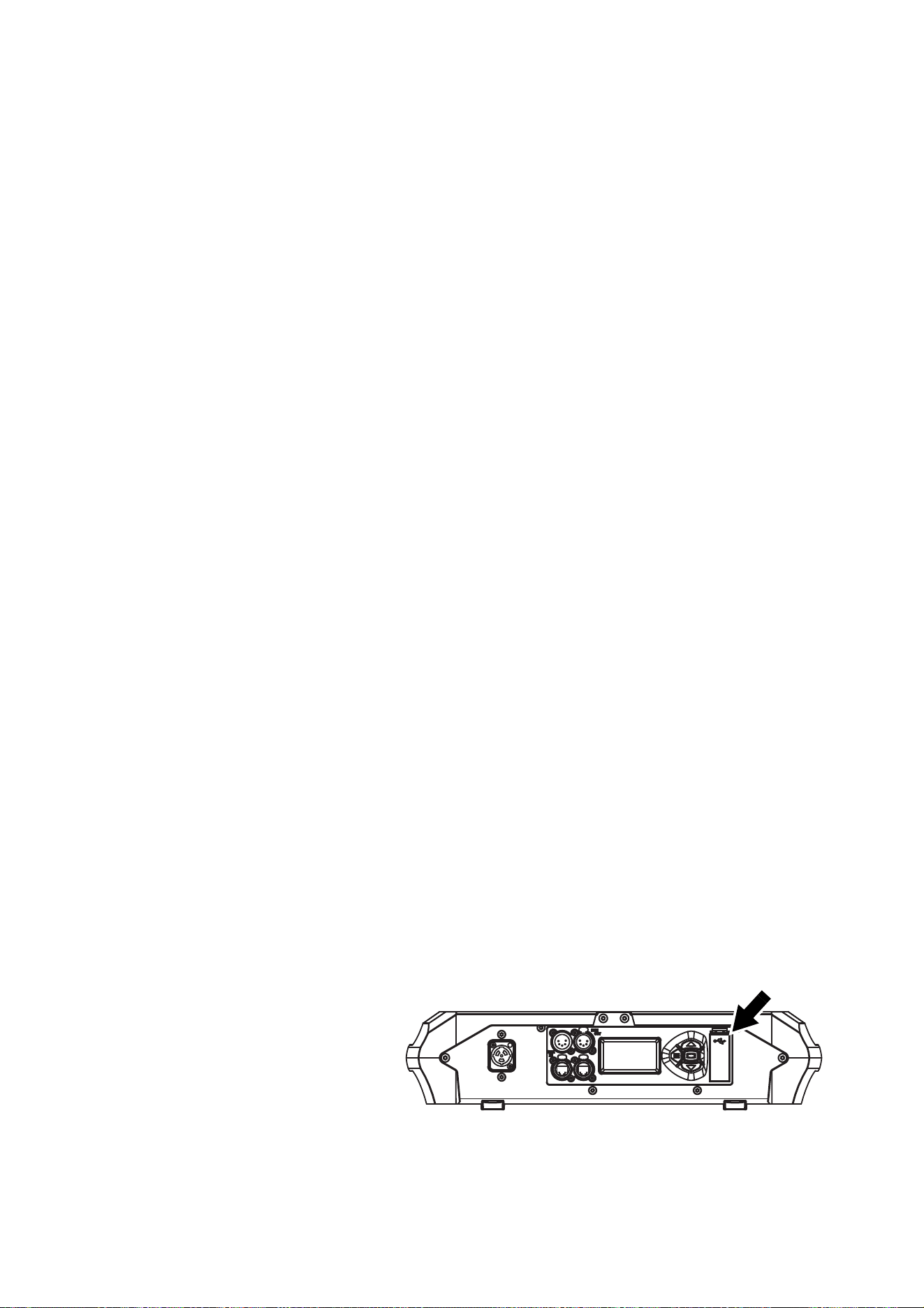
Service and maintenance
17
Cleaning
Regular cleaning is very important for fixture life and performance. Buildup of dust, dirt, smoke particles, fog
fluid residues, etc. degrades the fixture’s light output and cooling ability.
Cleaning schedules for lighting fixtures vary greatly depending on the operating environment. It is therefore
impossible to specify precise cleaning intervals for the MAC Ultra Performance. Cooling fans suck in
airborne dust and smoke particles, and in extreme cases fixtures may require cleaning after surprisingly few
hours of operation. Environmental factors that may result in a need for frequent cleaning include:
• Use of smoke or fog machines.
• High airflow rates (near air conditioning vents, for example).
• Presence of cigarette smoke.
• Airborne dust (from stage effects, building structures and fittings or the natural environment at outdoor
events, for example).
If one or more of these factors is present, inspect fixtures within their first few hours of operation to see
whether cleaning is necessary. Check again at frequent intervals. This procedure will allow you to assess
cleaning requirements in your particular situation. If in doubt, consult your Martin dealer about a suitable
maintenance schedule.
Follow these precautions when cleaning the fixture:
• Work in a clean, dry, well-lit area.
• Use gentle pressure only. Do not use any product that contains abrasives. Do not use solvents. Use care
when cleaning optical components: surfaces are fragile and easily scratched.
• Use a vacuum cleaner – do not use a pressurized air jet. A vacuum cleaner will remove dirt from the
fixture and from the area where you are working. An air jet may blow dirt into the fixture, and this can
cause visible objects in projections and possibly even damage to the fixture.
• Do not apply a strong vacuum directly to a cooling fan, as the strong airflow may spin the fan blades fast
enough to cause damage. Instead, hold the vacuum cleaner nozzle a few centimeters away from the fan
and dislodge dust with a soft brush.
Cleaning procedure
To clean the fixture:
1. Disconnect the fixture from power and allow it to cool for at least 30 minutes.
2. Vacuum dust and loose particles from the outside of the fixture and the air vents at the back and sides of
the head and in the base, using a soft brush to help dislodge dust.
3. Clean the front lens on the front of the head by wiping gently with a soft, clean, lint-free cloth moistened
with a weak detergent solution. Do not rub the surface hard: lift particles off with a soft repeated press.
Dry with a soft, clean, lint-free cloth or low-pressure compressed air. Remove stuck particles with an
unscented tissue or cotton swab moistened with glass cleaner or distilled water.
4. Check that the fixture is dry before reapplying power.
Battery replacement
Warning! Disconnect the fixture from AC power before replacing its battery. Do not attempt to recharge the
battery, or you may create a risk of fire or explosion. Replace the battery with one of the same type
only. New batteries are available from Martin (P/N 05801011).
The MAC Ultra Performance has
a non-rechargeable CR123A
3-volt lithium battery that
provides power to the control
panel and display when the
fixture is not connected to AC
mains power. If the battery runs
flat you must replace it with a
new one. Do not attempt to
recharge it.
Figure 9: Battery compartment
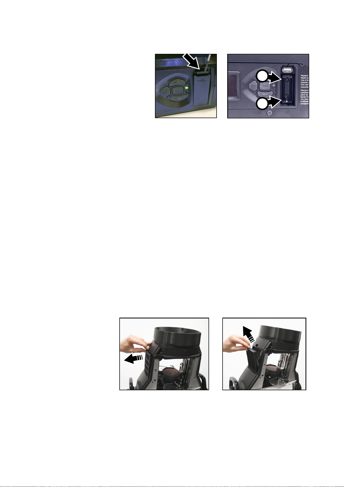
18
MAC Ultra Performance Safety and Installation Manual
See Figure 9. The battery is located in the USB port / battery compartment (arrowed) next to the control
panel on the base of the fixture.
To replace the battery:
1. Disconnect the fixture from AC
mains power and allow to cool.
2. See Figure 10. Push down on the
locking tab (arrowed) with a
screwdriver to release the USB
port / battery compartment cover
and remove the cover.
3. Remove the used battery and
insert a new one of the correct
type, respecting battery polarity
(positive terminal facing
downwards, away from the
head).
4. Reinstall the compartment cover and check that it is closed securely before reapplying power.
Send used batteries to an authorized waste recycling center for recycling. Do not treat a battery as
household waste.
Head air filter
The MAC Ultra Performance is protected from the entry of dirt and dust by an air filter in the head. Free
airflow through filters is important for effective cooling, effective performance and maximum product life. Air
filters therefore require periodical service.
Two types of air filter are available from Martin suppliers as service items for the MAC Ultra Performance:
• Re-usable air filters with a metal element, available as single filters (P/N 5132434-00).
• Disposable air filters with a paper element, available in sets of 12 filters (P/N 50400765).
Regardless of which type of filter the fixture is supplied with, you are of course free to choose which type
you will use. The metal filters can be cleaned and re-used. Note that the filter mesh is not as fine as with
paper filters, so the fixture may require internal cleaning at shorter intervals than you are used to.
Air filter service intervals depend on the environment the fixture is used in. Inspect air filters visually at
regular intervals. Clean the fixture’s metal re-usable filters – or replace paper filters – if they are visibly
contaminated by dust, dirt, residue from atmospheric effects, etc.
To service the head air filter:
1. Disconnect the fixture from power and allow components to cool for 30 minutes.
2. The air filter is located in the left-hand side of the head. Position the head so that the air filter cover is
accessible and apply the tilt lock (see Figure 1 on page 8).
3. See Figure 11.
Unclip the air
filter cover and
lift it off the
head.
4. Remove the air
filter from its
recess in the
head.
5. Dispose of
paper air filters.
Do not try to
clean or re-use
a paper air filter.
Clean metal air
filters with a soft
brush and vacuum cleaner or compressed air, taking care to avoid damaging the filter mesh. If metal
filters are greasy, you can clean them in a household dishwasher at maximum 50° C (122° F), short
cycle recommended. Dry them completely before reinstalling. The metal filter is designed to be re-used,
but replace it with a new item if it is not in clean, undamaged condition after cleaning.
Figure 10: Battery replacement
+
–
Figure 11: Releasing head air filter

Service and maintenance
19
6. Place the clean air filter into the space in the head, making sure that there is no gap for air to pass
through around the edges of the filter.
7. Hook the rear end of the filter cover into the head and push the front end of the cover into the head until
its clip engages fully. Check that the cover is held securely and cannot fall out of the head.
8. Release the tilt lock before applying power or packing the MAC Ultra Performance in its flightcase.
Lubrication
The MAC Ultra Performance does not require lubrication under normal circumstances. Moving parts can be
checked and a long-lasting Teflon-based grease reapplied by a Martin service partner if necessary.
Service utilities
The fixture’s SERVICE menu provides utilities for technicians rigging or servicing the fixture (see the MAC
Ultra Performance User Guide for full details of the control panel menus):
• ERROR LIST displays a list of any status messages stored in memory. Up to 20 messages can be
displayed.
• FAN CLEAN lets you set cooling fans to run at high speed to remove loose dust.
• PAN/TILT FEEDBACK lets you disable feedback to the fixture software from the pan, tilt and effects
positioning systems.
- If feedback is set to ON and a pan, tilt or effect position error is detected, the shutter closes and the
effect resets.
- This feature can be disabled by setting feedback to OFF. The OFF setting is not saved when the fixture
is powered off, and the system will be re-enabled the next time the fixture starts.
• ADJUST is for use by Martin Service only. Important! Do not use the items in this menu without guidance
or service documentation from Martin Service.
• For details of the CALIBRATION menu, see next section,
• USB provides two utilities:
- USB → FIRMWARE lets you update the firmware (fixture software) from a USB flash memory drive. For
a detailed guide to updating the firmware from a USB drive, see ”Installing using a USB memory
device” later in this chapter.
- USB → SERVICE LOG (available from firmware version 1.2.0 which is due for release mid-2021) lets
you save the fixture ID, current counter values and status messages stored in the fixture’s memory to a
USB flash memory drive. You can also delete all the status messages permanently from the fixture’s
memory.
Calibration
Martin fixtures are adjusted and calibrated at the factory, and further calibration should only be necessary if
fixtures have been subjected to abnormal shocks during transport or if normal wear and tear has affected
alignment after an extended period of use. You can also use calibration to fine-tune fixtures for a particular
location or application.
The SERVICE → CALIBRATION menu lets you define offsets in the fixture software to adjust the positions
of pan, tilt and effects relative to the DMX values the fixture receives. This allows you to fine-tune fixtures
and achieve uniform behavior in multiple fixtures.
We recommend the following procedure:
1. Aim a reference fixture and the fixtures that you want to calibrate at a flat surface. You can calibrate
fixtures one at a time or line up multiple fixtures in a row. Apply power and set pan, tilt and effects to the
same DMX values.
2. In each fixture, scroll through the effects in the SERVICE → CALIBRATION menu and adjust the
position of any effects that need calibration while comparing the light output with the reference fixture.
The calibration range available varies depending on the effect.
3. After selecting a value, press ENTER to confirm. The fixture will remember any new calibration values
that you have set, and the new positions will not be affected by powering the fixture off and on.

20
MAC Ultra Performance Safety and Installation Manual
Loading and storing default calibration offsets
• CALIBRATION → LOAD DEFAULTS lets you erase any custom calibration offsets that you have defined
and reload the default calibration offsets that are stored in memory.
• CALIBRATION → SAVE DEFAULTS lets you overwrite the factory default calibration offsets that are
stored in memory with any new offsets that you have defined.
Important! Overwriting is permanent. Once you have saved new default offsets, LOAD DEFAULTS will
load the new defaults, not the original factory defaults. Once you have used a CALIBRATION → SAVE
DEFAULTS command it will be impossible to restore the original factory defaults, even with a firmware
upload.
Installing firmware
Important! Do not switch the fixture off or disconnect the source of the firmware during an update, or the
firmware will be corrupted.
The currently installed firmware (fixture software) version appears briefly in the control panel display at
startup. You can also check it at any time in the INFORMATION menu in the fixture’s control panel.
Fixture information and settings are not affected when you upload new firmware to the fixture.
If you update firmware to a newer version, check the MAC Ultra Performance area of www.martin.com to
see whether updated versions of the Safety and Installation Manual and User Guide are available for the
fixture.
You need the following in order to install firmware:
• A Windows PC running the latest version of the Martin Companion software suite that is available for
download from the Martin website at www.martin.com.
• The latest MAC Ultra Performance firmware files. Martin Companion automatically downloads these from
the Martin fixture firmware cloud when you run Martin Companion on a PC that is connected to the
Internet.
•Either:
- a Martin Companion Cable USB-DMX hardware interface (you can find information about this product
on the Martin website at www.martin.com), or
- a USB flash memory drive formatted in Windows using the FAT32 file system.
Installing using a Martin Companion Cable
If you use a Martin Companion Cable it is possible to update multiple fixtures in one operation. All MAC Ultra
Performance fixtures that are powered on and connected via a DMX link to the fixture that you update will
also have their firmware updated.
To install the MAC Ultra Performance firmware using a Martin Companion Cable:
1. Apply power to the MAC Ultra Performance fixture (or fixtures) and allow it (or them) to boot.
2. Connect the Martin Companion Cable’s USB connector to a USB port on your PC. Connect the Martin
Companion Cable’s XLR connector to either the fixture’s DMX IN connector or the DMX link.
3. Start the PC and launch Martin Companion. Check that the Martin Companion application correctly
detects the Martin Companion Cable (a green dot should appear next to USB Connected in the top
right-hand corner of the window).
4. In Martin Companion’s Firmware - Fixture Update window, locate the MAC Ultra Performance firmware
version that you want to install.
5. Start the firmware update by clicking Update Firmware in Martin Companion. Do not disconnect the
Martin Companion Cable or power off the fixture(s) until the upload is complete and the fixture(s) have
successfully rebooted. If you are updating multiple fixtures over the DMX link, check that they have all
rebooted correctly.
6. The newly-installed firmware version will now be displayed in the INFORMATION menu.
Installing using a USB memory device
To install the MAC Ultra Performance firmware in one fixture using a USB flash memory drive:
1. Launch the Martin Companion software suite on a PC that is connected to the Internet. Martin
Companion will automatically download the latest Martin firmware files from the Martin cloud.
2. In Martin Companion’s Firmware - Fixture Update window, click on Download USB Stick Firmware
and navigate to the root directory of the USB drive where you want to save the firmware.
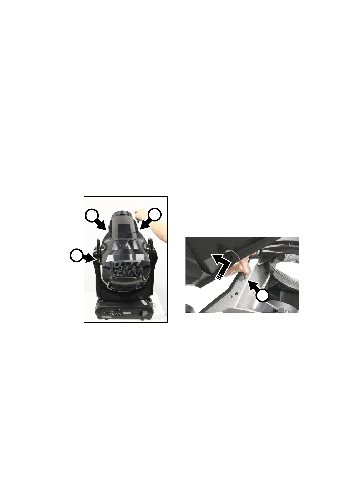
Service and maintenance
21
3. Click on Select Folder. Martin Companion will automatically save the firmware files in a correctly named
folder to the USB drive’s root directory.
4. When you see a Download Successful message you can close Martin Companion. Check that the
USB drive now contains a folder whose name is the fixture type and software version. Then use an Eject
command in Windows to make sure that you can remove the drive safely, and remove the drive from the
PC.
5. Apply power to the fixture and allow it to boot. Insert the USB drive into the USB host socket next to the
fixture’s control panel. The fixture should illuminate the display and the contents of the root directory
should appear in the display. If the fixture does not recognize the USB drive automatically, navigate to
SERVICE
→ USB in the control panel.
6. Scroll to the folder that contains the update files on the USB drive. Select the folder and press ENTER.
The update will begin automatically and the display will show progress status. At the end of the update
process the fixture will reboot. Do not remove the USB drive until the reboot is complete.
7. Remove the USB drive from the fixture. The newly-installed firmware version will now be displayed in the
INFORMATION menu.
Opening the head for access
To open the head for access to the rotating gobos:
1. Disconnect the fixture from power and allow to cool for 30 minutes.
2. Place the fixture on a suitable work surface.
3. See Figure 12. Position the fixture so that the Martin logo on the back of the head is the right way up.
The top and bottom head covers are now on the top and bottom of the head respectively. Apply the tilt
lock A.
4. Remove the two retaining screws B from the top head cover, slide the cover towards the front of the
fixture to release the back of the cover, and lift the cover away from the head slightly. Press the retaining
clip C on the cover’s safety wire in towards the head chassis, slide the clip along its slot until you can
remove it, and then remove the safety wire and head cover completely from the fixture.
5. Release the tilt lock, reposition the head and remove the bottom head cover in the same way.
When closing the head, follow the above procedure in reverse. Check that the head covers are held
securely after you have reinstalled them, and release the tilt lock before reapplying power or packing the
MAC Ultra Performance in its flightcase.
Figure 12: Removing the head covers
B
B
C
A

22
MAC Ultra Performance Safety and Installation Manual
Rotating gobo replacement
The MAC Ultra Performance uses specially designed borosilicate 3.3 rotating gobos. The gobos are a
custom size. Their external diameter is 37.5 mm +0/-0.2 mm (1.476 in. +0/-0.008 in.), and the image
diameter is 30 mm (1.181 in.). The gobo thickness is 1.1 mm +/- 0.1 mm (0.04 in. +/- 0.004 in.). The gobos
are manufactured in Borofloat 33 glass with a heavy matted aluminum coating.
Although the goboholders on Gobo Wheel 1 are different from the goboholders on Gobo Wheel 2, the actual
gobos are the same type and size and can be interchanged no matter which wheel they are installed on.
Replacement gobos must have the same dimensions, construction, materials and quality as the gobos
supplied as standard. Using gobos that do not meet this requirement – such as metal gobos – will very
probably cause damage that is not covered by the product warranty.
Optical components have fragile coatings and are exposed to very high temperatures. Handle and store
components with care.
See the MAC Ultra Performance User Guide (available for download from the product pages on
www.martin.com) for names, illustrations and part numbers of the gobos installed as standard.
Avoiding damage to gobos
Follow these precautions when handling, using and storing gobos:
• Do not use gobos with dark coatings on either side, as these will absorb heat – either directly from the
light source or reflected back from other optical components – and will not be durable.
• Do not use metal gobos in the MAC Ultra Performance: their durability may be reduced when used in this
fixture.
• Store all gobos in a dust-free environment with approx. 50% humidity.
• Wear clean nitrile cleanroom gloves when handling gobos.
• Avoid scratching coated and uncoated sides.
• Do not place a gobo with the coated side face-down on any surface.
• Avoid touching the other gobos when removing a gobo from a rack: the sharp edge of one gobo can
scratch the others.
• Keep gobos perfectly clean to reduce the risk of heat damage.
• When cleaning gobos, use a repeated dabbing action rather than a rubbing action. When rinsing, use
distilled or even better deionized water to avoid residue that will appear as drying marks.
• If possible, clean the coated side of gobos with dust and oil-free compressed air only. If the coated side is
contaminated with oil, clean with isopropyl alcohol and optics cleaning tissues.
• Clean the uncoated side of gobos with isopropyl alcohol or photographic quality lens-cleaner and optics
cleaning tissues.
• Do not try to clean gobos in an ultrasound bath, as this may cause delamination of the coating.
• Do not use acidic or alkaline cleaning solutions, as they will attack the aluminum coating.
• Correct gobo orientation is critical. Read the guidelines given later in this chapter carefully before
installing a gobo.
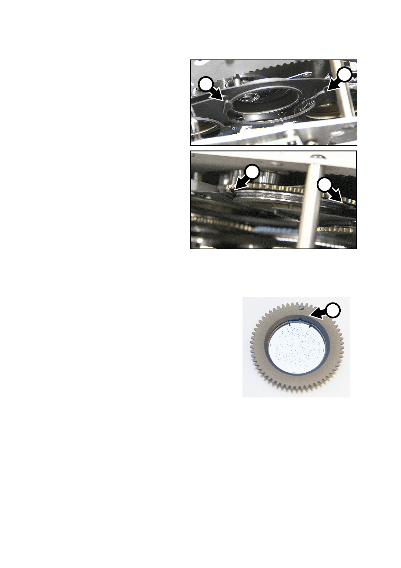
Service and maintenance
23
Goboholder clips
See Figure 13. The goboholders in
both gobo wheels are held in
position by clips. When you install a
gobo in a gobo wheel, you must
make sure that the jaws of the clip
A engage in the flange in the
goboholder on both sides of the
goboholder as shown at B.
Replacing a rotating
gobo on Gobo Wheel 1
Gobo Wheel 1, the aerial wheel, is
the wheel that is closer to the LEDs
at the back of the head. To replace
a rotating gobo on Gobo Wheel 1:
1. If you have not already removed
the top head cover, remove it as
described in “Opening the head
for access” on page 21.
2. With your fingers, rotate the
gobo that you want to remove
so that you line up a reference
point (for example, the magnet
and marking C shown in Figure
14) on the goboholder with a
reference point in the module.
B
B
Figure 13: Goboholder clip and corresponding flange in
the goboholder
A
A
C
Figure 14: Goboholder reference mark
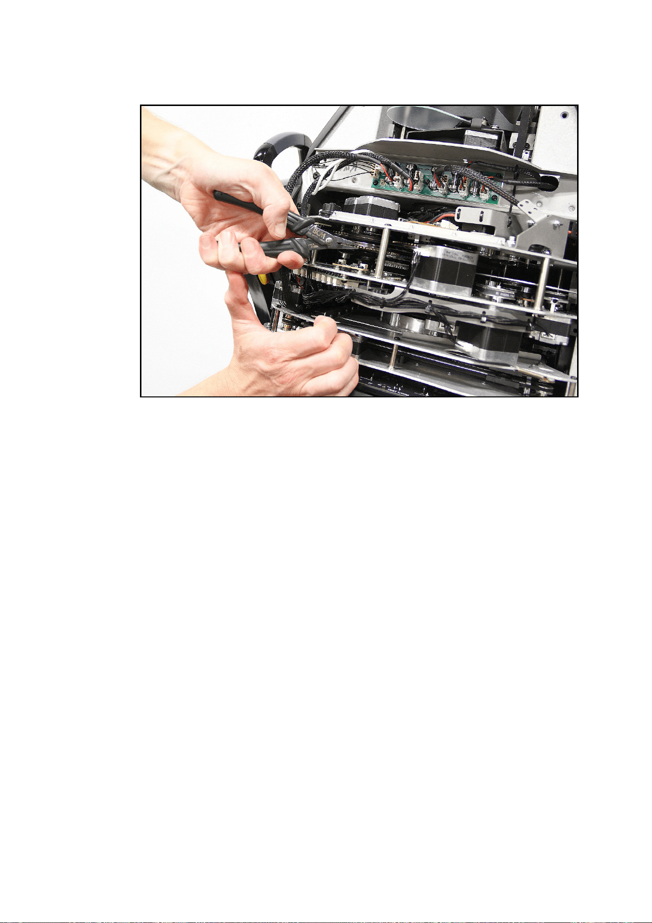
24
MAC Ultra Performance Safety and Installation Manual
3. See Figure 15. Using a pair of flat-nosed pliers, grasp the teeth of the goboholder firmly and pull the
goboholder out of its clip in the gobo wheel.
4. For instructions on how to install a new gobo in a goboholder, see “Replacing a gobo in a goboholder” on
page 26.
5. Goboholders are held in position in the gobo wheel by clips (see Figure 13 on page 23). When you
reinstall the goboholder, you must make sure that the jaws of the clip engage in the flange in the
goboholder on both sides of the goboholder.
6. Line up your reference point on the goboholder with your reference point in the effects module. Holding
the goboholder teeth with flat-nosed pliers, slide the goboholder back into the jaws of the clip in the gobo
wheel.
7. Check that the gobo is pushed fully into the clip and held securely. To check that the goboholder is
correctly installed, rotate the goboholder at least 180° in both directions in the gobo wheel and check
that it and all the other goboholders move freely.
8. If you have finished service work, reinstall the top head cover and its safety cable with reference to
“Opening the head for access” on page 21.
Figure 15: Removing a goboholder from Gobo Wheel 1
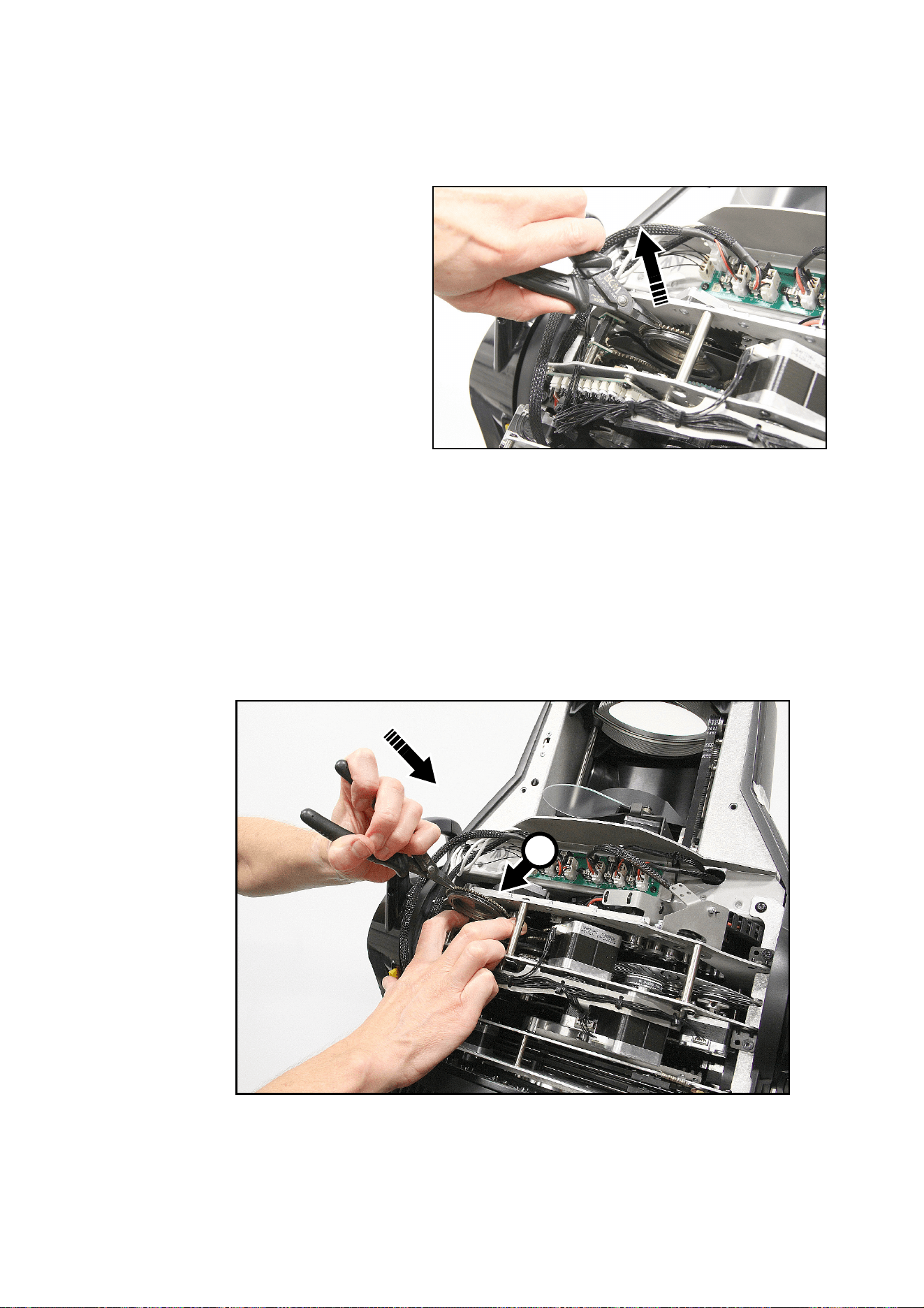
Service and maintenance
25
Replacing a rotating gobo on Gobo Wheel 2
Gobo wheels 1 and 2 sit very close to each other in the effects module, in almost the same plane of focus.
Gobo wheel 2, the breakup wheel, is the wheel that is closer to the front lens. To replace a rotating gobo on
Gobo Wheel 2:
1. Remove the top head cover as
described in the previous section.
2. See Figure 16. With your fingers,
rotate the gobo that you want to
remove so that you line up a
reference point (for example, the
marking C shown in Figure 14 on
page 23) on the goboholder with a
reference point in the module.
3. Using a pair of flat-nosed pliers,
grasp the teeth of the goboholder
firmly and pull it out of its clip in
the gobo wheel.
4. For instructions on how to install a
new gobo in a goboholder, see
“Replacing a gobo in a
goboholder” on page 26.
5. Goboholders are held in position
in the gobo wheel by clips (see
Figure 13 on page 23). When you reinstall the goboholder, you must make sure that the jaws of the clip
engage in the flange in the goboholder on both sides of the goboholder.
6. See Figure 17. Line up your reference point on the goboholder with your reference point in the effects
module. Using two fingers as shown at D, bend the thin metal plate on the gobo wheel away from the
wheel very slightly so that you have room to slide the goboholder back into the clip in the gobo wheel.
Holding the goboholder teeth with flat-nosed pliers, slide the goboholder back into its clip.
7. Check that the gobo is pushed fully into its clip and held securely. To check that the goboholder is
correctly installed, rotate the goboholder at least 180° in both directions in the gobo wheel and check
that it and all the other goboholders move freely.
8. If you have finished service work, reinstall the top head cover and its safety cable with reference to
“Opening the head for access” on page 21.
Figure 16: Removing a gobo from Gobo Wheel 2
Figure 17: Reinstalling a goboholder
D
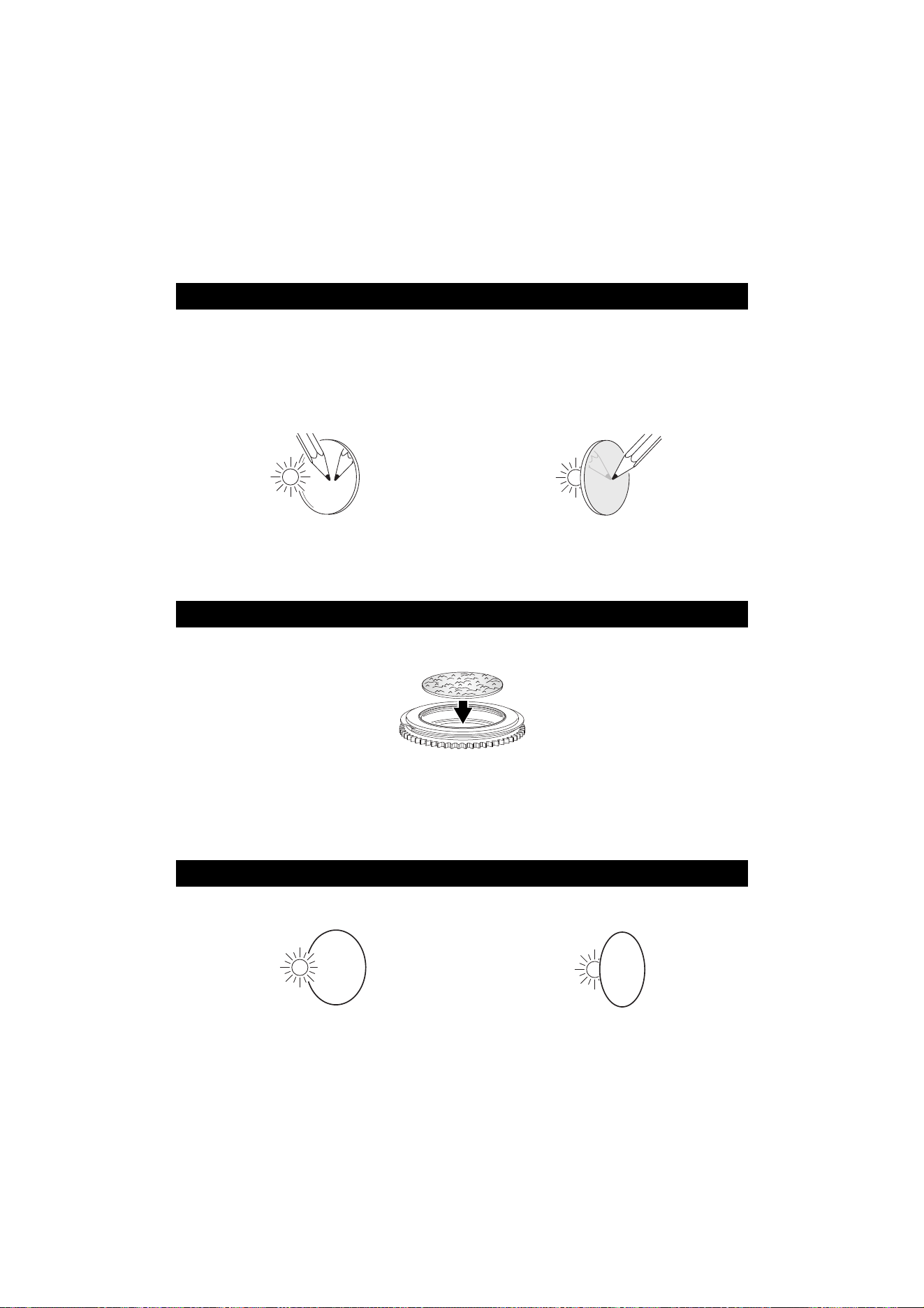
26
MAC Ultra Performance Safety and Installation Manual
Replacing a gobo in a goboholder
The rotating gobos in the MAC Ultra Performance are held in their holders by springs and can be removed
from their holders as described in this section.
Gobo orientation: general
Make sure that you install gobos facing in the correct direction, or they may suffer heat damage. The
orientations shown in Figure 18 are correct in most cases, but consult your Martin dealer or gobo supplier if
you are in any doubt about the orientation of a specific gobo type.
Coated Glass Gobos
The heavy matted aluminum coated borosilicate gobos in the MAC Ultra Performance are
factory-installed with the more reflective sides facing towards the LED light source.
Replacement gobos must also be installed with more reflective sides facing the LEDs in
order to avoid heat damage.
More reflective side towards LEDs
To minimize the risk of gobo overheating
and damage, turn the more reflective side of
a coated gobo towards the lamp.
Less reflective side away from LEDs
The less reflective side of a coated gobo will
absorb less heat if it faces away from the
lamp.
Textured Glass Gobos
Flat side towards goboholder
If you install a textured glass gobo in the fixture, note that a textured glass gobo sits most
squarely in a goboholder with the flat side placed down into the recess in the goboholder. If
in doubt, consult your Martin dealer or gobo supplier. We recommend that textured glass
gobos are glued into the goboholder.
Image / text Gobos
True image towards LEDs Reversed image away from LEDs
Gobos that have a specific left/right orientation (such as text gobos) will appear correctly in
the projection if they appear correctly when viewed from the side that faces towards the
LED light source.
Figure 18. Correct gobo orientation
abc
abc
abc
abc
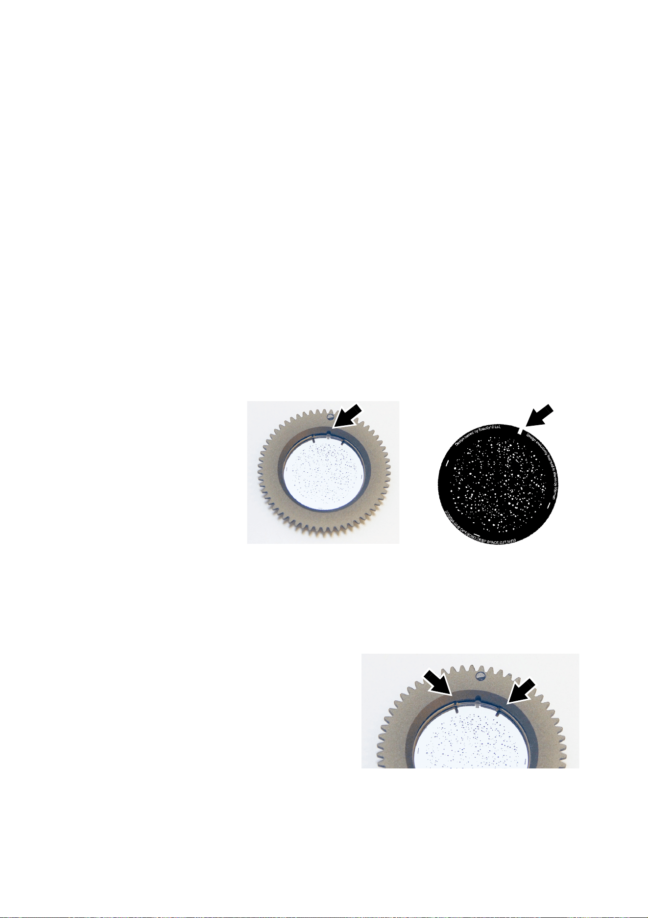
Service and maintenance
27
Goboholder and gobo orientation, Gobo Wheel 1 (Aerial Wheel)
• Gobo Wheel 1 is the wheel that is closest to the LED light source.
• The side of the goboholder with the gobo retaining spring and with the teeth faces towards the LED light
source.
• The shiny side of the gobo faces towards the spring and towards the teeth in the goboholder so that it
faces towards the LED light source.
• The white, non-reflective side of the gobo faces away from the spring and away from the teeth in the
goboholder so that it faces towards the front lens.
Goboholder and gobo orientation, Gobo Wheel 2 (Breakup Wheel)
• Gobo Wheel 2 is the wheel that is closest to the front lens.
• The side of the goboholder with the gobo retaining spring and without the teeth faces towards the LED
light source.
• The shiny side of the gobo faces towards the spring and away from the teeth in the goboholder so that it
faces towards the LED light source.
• The white, non-reflective side of the gobo faces away from the spring and towards the teeth in the
goboholder so that it faces towards the front lens.
Gobo orientation, Wheels 1 and 2
On both gobo wheels in the MAC Ultra Performance:
• Images or text on gobos must appear correctly (i.e. not flipped left to right) when looking at the
goboholder from the side with the spring.
• The textured side of textured glass gobos must always face towards the spring. The flat side of textured
gobos must face downwards so that the gobo sits flat in the goboholder.
Gobo alignment
See Figure 19. Note
the position of the
alignment marks
(arrowed) on
goboholders and
gobos. Install gobos
with the alignment
marks next to each
other.
Gobo replacement
procedure
Avoid getting grease from your fingers or dirt
onto gobos. Hold gobos by their edges only.
Wear clean nitrile cleanroom gloves when
handling gobos.
To replace a gobo in a goboholder:
1. See Figure 20. Place the goboholder on a
clean surface with the recess for the gobo
and gobo spring facing upwards. Note the
position of the bends (arrowed) in the ends of
the gobo retaining spring. Using a plastic
lever to avoid scratching the gobo, lever one
end of the retaining spring out of the groove
in the goboholder and lift the retaining spring
out of the goboholder.
Figure 19: Gobo alignment marks
‘Deep Space’, Gobo Wheel 1
Figure 20: Gobo retaining spring
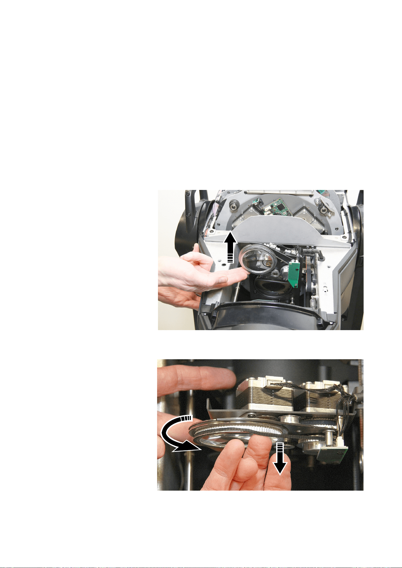
28
MAC Ultra Performance Safety and Installation Manual
2. Turn the goboholder over so that the recess faces downwards and let the gobo fall out of the holder onto
a clean, soft surface. Turn the goboholder back again and put it on the surface teeth with the recess
facing upwards.
3. Holding the new gobo by its edges, insert it into the goboholder with the alignment marks on gobo and
goboholder correctly lined up. The correct gobo orientation is different for Gobo Wheels 1 and 2. Make
sure that you insert the gobo facing the correct way round by referring to the guidelines on pages 26 and
27.
4. Check that the gobo is seated flat in the holder. See Figure 20. Insert the retaining spring into the
goboholder and press it into its groove in the goboholder. Check that the spring is pressed as flat as
possible against the gobo and that the gobo is held securely in the goboholder.
5. Reinstall the goboholder in the gobo wheel and reinstall the top head cover following the directions given
earlier in this section.
Replacing the prism with a frost filter
The MAC Ultra Performance is supplied with a rotating prism installed. It is possible to replace the prism
with a heavy frost filter, P/N MAR-91614060HU. To remove the prism and install the heavy frost filter:
1. Following the
instructions in
“Opening the head for
access” on page 21,
remove the bottom
head cover.
2. Position the head with
the open lower side of
the head facing
upwards towards you
and apply the tilt lock.
3. See Figure 21. Lift the
prism up towards you
so that you have good
access to it.
4. See Figure 22. Rotate
the prism counter-
clockwise while at the
same time pulling the
prism drive belt over
the lip of its channel in
the prism holder, so
that the belt is
gradually drawn out of
the channel.
Figure 21: Lifting up the prism
Figure 22: Disengaging the prism drive belt
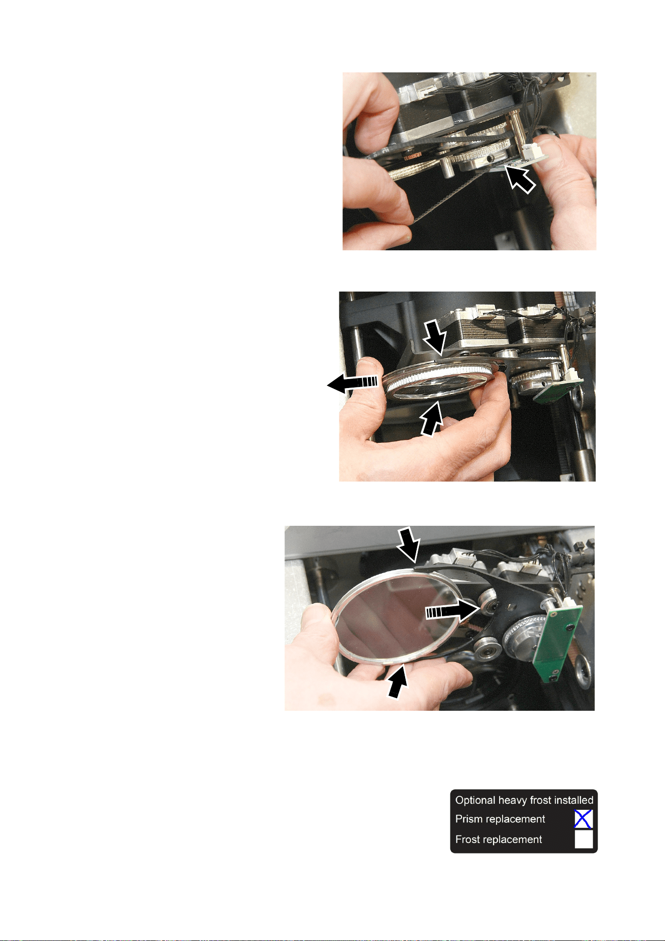
Service and maintenance
29
5. See Figure 23. When the drive belt is
free of the prism, twist it so that it will
pass sideways through the gap
(arrowed) between the prism drive
pulley and the sensor PCB. Lift the
belt up through this gap and remove it
from the head. If the belt is in good
condition, store it for possible re-use.
6. See Figure 24. Slide the prism out of
the jaws (arrowed) that it sits in. Store
it for possible re-use.
7. The frost filter is glued into
a metal holder. Look
carefully at the holder and
note which side of the
holder the glass is glued
into. Turn the frost filter so
that this side – the side that
the glass is glued into –
faces towards the back of
the fixture. See Figure 25.
Slide the filter into the jaws
(arrowed) and check that it
is held securely.
8. If you touched the glass
with your fingers, clean it
with a soft, clean, lint-free
cloth moistened in a little
isopropyl alcohol/distilled
water solution or
photographic lens cleaner.
9. Reinstall the bottom head cover following the directions given earlier in this section.
A label is supplied with the heavy frost filter (see on right). If you
replace the prism with the heavy frost filter, you may find it helpful to
stick this label on the base of the fixture and check the box marked
‘Prism replacement’ so that you can identify fixtures that have had the
heavy frost modification.
Figure 23: Disengaging the prism drive belt
Figure 24: Removing the prism
Figure 25: Installing the frost filter
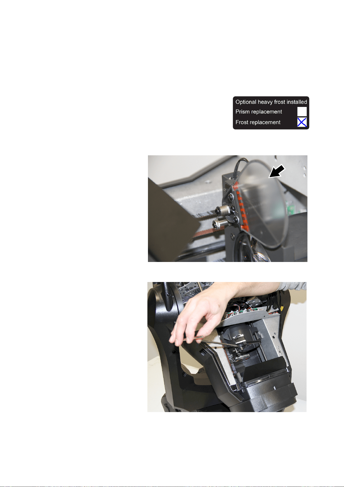
30
MAC Ultra Performance Safety and Installation Manual
Replacing the standard frost with a heavy frost
filter
The MAC Ultra Performance is supplied with a light frost filter installed as standard. It is possible to replace
this with a heavy frost filter, P/N MAR-91614063HU, MAC Ultra Heavy Frost - Frost Replacement. The
advantages of installing this filter are that, unlike the prism replacement filter described on the previous
pages, you to keep the prism in the fixture, and also that the frost replacement filter can be inserted
gradually into the beam whereas the prism replacement filter is either in or out.
If you replace the standard frost filter with a heavy frost filter, you may
find it helpful to stick the label (see on right) supplied with the heavy
frost filter on the base of the fixture and check the box marked ‘Frost
replacement’ so that you can identify fixtures that have had the heavy
frost modification.
To remove the existing standard frost filter and install the heavy frost filter:
1. Following the instructions
in “Opening the head for
access” on page 21,
remove the top head cover.
2. Position the head with the
top side of the head facing
towards you.
3. Move the zoom car
towards the front of the
head to give you easier
access to the frost filter
(arrowed in Figure 26). If
you let the head sink so
that it points downwards,
gravity will hold the zoom
car away from the filter.
4. See Figure 27. Use a
2 mm Allen wrench to
loosen the grub screw in
the end of the filter to
unfasten the filter from its
shaft.
Figure 26: Frost filter
Figure 27: Unfastening the frost filter from its shaft
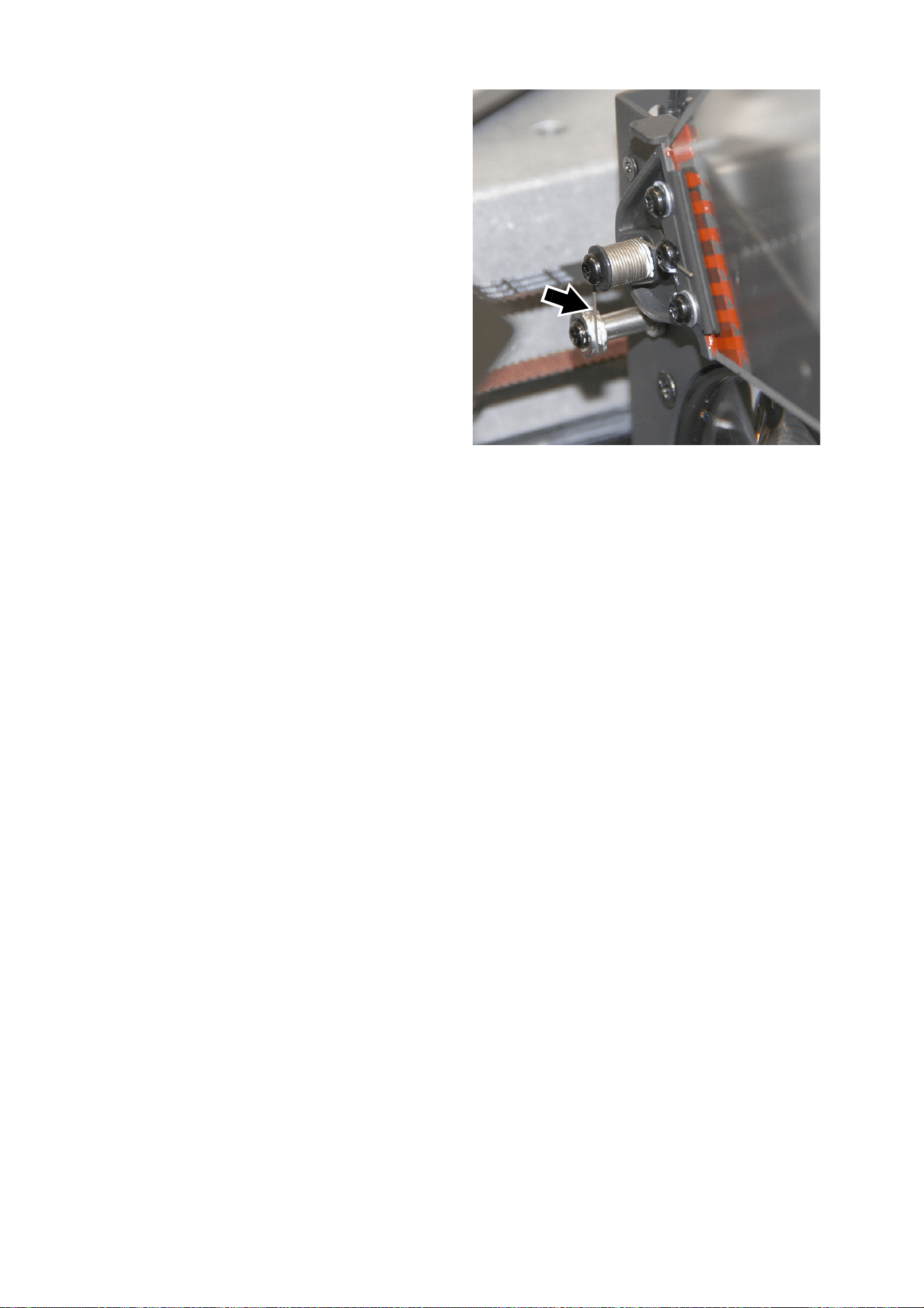
Service and maintenance
31
5. See Figure 28. Lift the end of the frost
filter spring (arrowed) out of its groove
in the spring anchor post. Do not
remove the high-temperature lubricant
from the anchor post.
6. Lift the filter together with its spring off
its shaft.
7. Note the position of the flat on the
shaft and the position of the grub
screw in the end of the new frost filter.
Slide the new filter onto the shaft in the
same orientation as the filter that you
removed. Use a 2 mm Allen wrench to
tighten the grub screw against the flat
in the shaft so that the filter is held
firmly on the shaft. Check that the filter
is secure, retightening the Allen screw
if necessary.
8. See Figure 28. If necessary, spread
the high-temperature lubricant on the
spring anchor post around a little so
that it will lubricate the new frost filter
spring. Then engage the end of the
spring (arrowed) in the groove in the
spring anchor post as shown.
9. If you touched the frost filter glass with your fingers, clean it with a soft, clean, lint-free cloth moistened in
a little isopropyl alcohol/distilled water solution or photographic lens cleaner.
10. Reinstall the top head cover following the directions given earlier in this section.
Figure 28: Frost filter spring

32
MAC Ultra Performance Safety and Installation Manual
Using the fixture
Before using the fixture, download and read the latest version of the MAC Ultra Performance User Guide
from the MAC Ultra Performance area of the Martin website at www.martin.com. The User Guide contains
details of:
• The effects available in the fixture.
• The control options available using DMX and/or RDM.
• The setup, monitoring and control options available using the onboard control and display panel.
• Software service functions.
Warning! Before applying power to the fixture:
• Read the safety information section of this manual starting on page 4.
• Read “Applying power” on page 13.
• Check that the installation is safe and secure.
• Check that the base is fastened securely so that the torque reaction when the head moves will not
cause the base to move.
• Check that the head tilt lock is released (see “Tilt lock” on page 8).
• Be prepared for the fixture to light up suddenly. Check that no-one is looking at the fixture from
close range.
• Be prepared for the head to move suddenly. Check that there will be no risk of collision with
persons or objects.
• In a hot or cold environment, check the temperature. Do not operate the fixture if the ambient
temperature is below 5° C (41° F) or above 40° C (104° F).
The MAC Ultra Performance does not have an On/Off switch. To apply power to the fixture, apply power to
the power input cable. Neutrik powerCON TRUE1 (TOP) connectors also support hot-plugging.
Battery power
The MAC Ultra Performance’s battery gives access to the most important functions in the control panel
when the fixture is not connected to AC mains power.
The battery is not rechargeable. Do not try to recharge it, or you may create a risk of fire or explosion.
The following functions are available on battery power:
• DMX and Ethernet addressing and setup
• Fixture ID
• PERSONALITY menu
• DEFAULT SETTINGS loading and saving
• INFORMATION menu
To activate the display when the fixture is not connected to mains power, press MENU. Press MENU again
to enter the menus.
The display extinguishes after 10 seconds with no user input and the control panel is de-activated after one
minute with no user input. Press MENU again to re-activate.

Troubleshooting
33
Troubleshooting
Compliance and legal
Approvals
This product has been tested and found to comply with the following standards:
- Global CB Certification/IECEE: IEC 60598-2-17 (IEC 60598-1)
- EU safety: EN 60598-2-17 (EN 60598-1), EN 62471, EN62493
- EU EMC: EN 55015, EN 55032, EN 55035, EN 61000-3-2, EN
61000-3-11, EN 61547
- US safety: UL1573
- US EMC: FCC Part 15 Class B
- Canadian safety: CSA C22.2 No. 166
- Canadian EMC: ICES-003 Class B; ICES-005 Class B
- United Kingdom: UKCA
- Australia/NZ: RCM
Problem Probable cause(s) Remedy
One or more of the fixtures is
completely dead.
No power to fixture.
Check that power is switched on and cables are
plugged in.
Fuse blown or internal fault.
Contact Martin Service or authorized service
partner. Do not remove base or yoke covers,
attempt to replace a fuse or carry out any repairs or
service that are not described in this Safety and
Installation Manual unless you have both
authorization from Martin and official Martin service
documentation.
Fixtures reset correctly but
respond erratically or not at all
to the controller.
Bad data link.
Inspect connections and cables. Correct poor
connections. Repair or replace damaged cables.
Data link not terminated.
Insert DMX termination plug in data output socket
of the last MAC Ultra Performance on the data link.
Incorrect addressing of fixtures. Check fixture address and protocol settings.
One of the fixtures is defective and is
disturbing data transmission on the link.
Unplug the data in and out connectors and connect
them directly together, or insert a relay cable, to
bypass one fixture at a time until normal operation
is regained. Have the fixture serviced by a qualified
technician.
Power fixtures off and on again to see if a restart
solves the issue.
Timeout error after fixture reset. Effect requires mechanical adjustment.
Check fixture’s stored error messages for more
information. Contact Martin Service or authorized
Martin service partner.
Mechanical effect loses
position.
Mechanical train requires cleaning,
adjustment, or lubrication.
Check fixture’s stored error messages for more
information. Contact Martin Service or authorized
Martin service partner.
Light output cuts out
intermittently.
Fixture is too hot.
Check fixture’s stored error messages for more
information.
Allow fixture to cool.
Clean fixture.
Reduce ambient temperature.
Control panel display only
operates when fixture is
connected to AC mains power.
Onboard battery fully discharged.
Replace battery with new one of same type (battery
is not rechargeable).
Table 2: Troubleshooting

34
MAC Ultra Performance Safety and Installation Manual
FCC Compliance
This equipment has been tested and found to comply with the limits for a Class B digital device, pursuant to part 15 of the FCC Rules.
These limits are designed to provide reasonable protection against harmful interference when the equipment is operated in a commercial
environment. This equipment generates, uses and can radiate radio frequency energy and, if not installed and used in accordance with
the instructions, may cause harmful interference to radio communications. Operation of this equipment in a residential area is likely to
cause harmful interference, in which case the user will be required to correct the interference at his own expense.
Supplier’s Declaration of Conformity
Harman Professional, Inc. have issued an FCC Supplier’s Declaration of Conformity for this product. The Declaration of Conformity is
available for download from the MAC Ultra Performance area of the Martin website at www.martin.com
Canadian Interference-Causing Equipment Regulations - Règlement sur le Matériel Brouilleur du Canada
This Class B digital apparatus meets all requirements of the Canadian Interference-Causing Equipment Regulations.
Cet appareil numérique de la classe B respecte toutes les exigences du Règlement sur le Matériel Brouilleur du Canada.
CAN ICES-003 (B) / NMB-003 (B); CAN ICES-005 (B) / NMB-005 (B)
EU Declaration of Conformity
An EU Declaration of Conformity covering this product is available for download from the MAC Ultra Performance area of the Martin
website at www.martin.com.
Conditional connection
For conformity with mains voltage fluctuations and flicker according to EN61000-3-11 during extensive use of continuous strobe effects
the user must determine, in consultation with the mains power supply authority if necessary, that the equipment is connected to a supply
impedance of less than 0.39 ohms at 50 Hz.
Hibernation Mode
’Hibernation mode’ is intended as an option to reduce the consequences of having a product fully operational in dirty environments or in
situations where noise level is crucial such as during live performances. The small reduction in energy consumption in Hibernation Mode
is only a subordinate effect.
Intellectual Property Rights
Martin® MAC Ultra Performance products are covered by one or more of these patents:
CN101430080; CN102713425; CNZL200810128720.0; CNZL200810128776.6; CNZL200810144668.8; CNZL201080025103.3;
CNZL201180014884.0; CNZL201380004370.6; CZ17567; EP2058586; EP2113714; EP2117284; EP2136136; EP2326150;
EP2443381; EP2536974; EP2550686; EP2828577; EP2881650; US6971770; US7,703,948; US7,789,543; US7,905,630;
US7,942,535; US7,990,673; US7222997; US7498756; US8,449,141; US8,708,535; US8,770,762; US9217551; US9217559;
and/or one or more of these patent applications:
CN104696882; CN104698579; CN104976548; CN105402641; CN201410740291.8; CN201410742572; DKPA201700088;
EP17167067.2; EP2091302; EP2881651; EP2881652; EP2881653; EP2927579; EP2995852; US2015/0285483; US20150159827;
US20150159828; US20150159830; US20160069540; US20160102850;
and/or one or more other intellectual property rights, including one or more intellectual property rights listed on www.martin.com/ipr
Disposing of this product
Martin products are supplied in compliance with Directive 2012/19/EC of the European Parliament and of the Council
of the European Union on WEEE (Waste Electrical and Electronic Equipment), where applicable.
Help preserve the environment! Ensure that this product is recycled at the end of its life. Your supplier can give details
of local arrangements for the disposal of Martin products.
The MAC Ultra Performance contains a lithium battery. Ensure that the battery is disposed of correctly and responsibly
by an authorized recycling or waste disposal center at the end of its life. Where applicable, Martin participates in
schemes whose aim is to ensure that local recycling and/or waste disposal centers accept batteries from Martin
products.

www.martin.com
