
e
After you have removed
bike from the steel crate
and cardboard box:
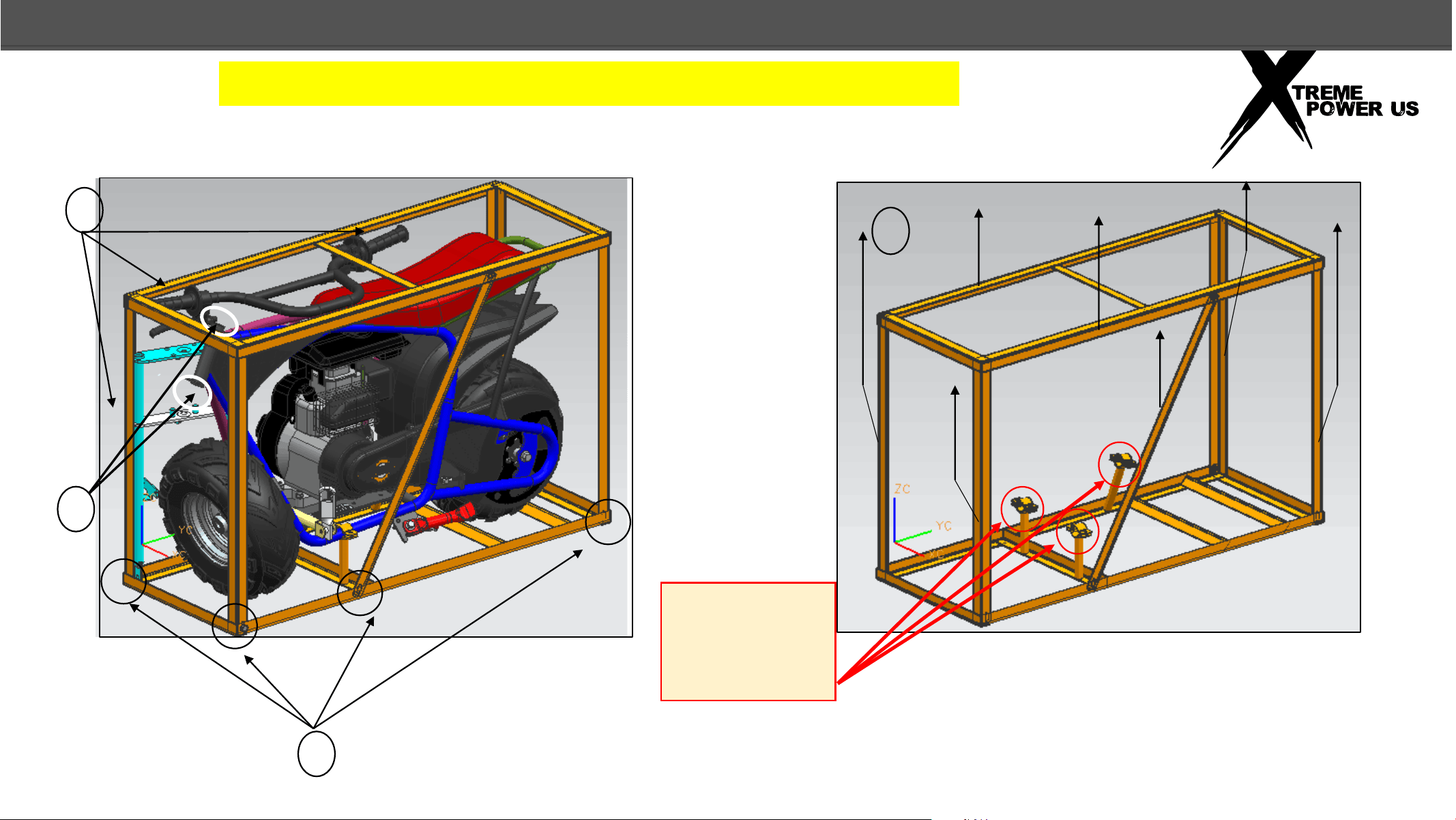
1) Cut the ties that
secure the
handlebar and front
fork to the steel
packing frame
2) Remove the bolt and
nut that secures the
mini bike steering
head to the top steel
shipping crate
3) Loosen and remove
the 6 bolts and nuts
that secure the
upper steel crate
and vertical supports
to the crate base.
NOTE: Do not loosen
the 3 supports on
the bottom of the
steel shipping crate
that attach to the
mini bike frame.
4) Lift off the upper
steel crate with the
vertical supports and
discard.
1
2
3
2
UNPACKING
WEAR
PROTECTIVE GLOVES WHEN HANDLING THE STEEL CRATE
4
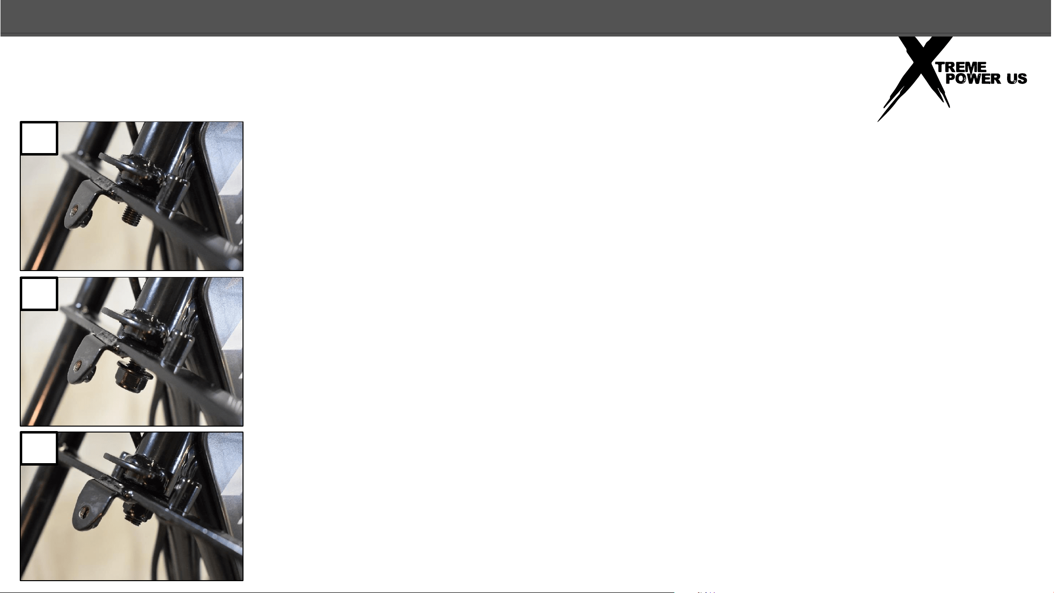
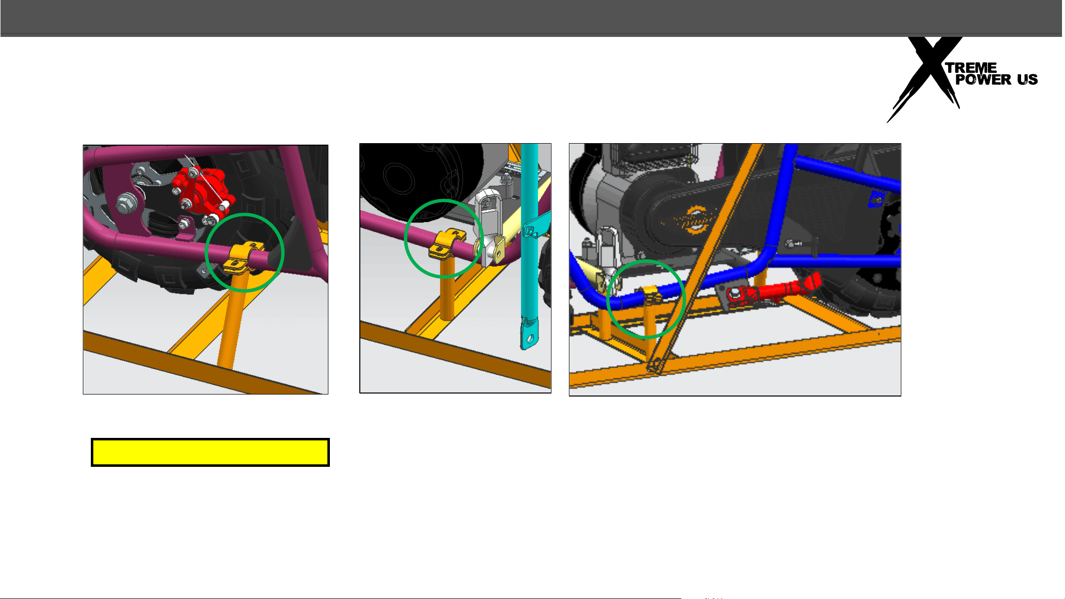
ASSEMBLY
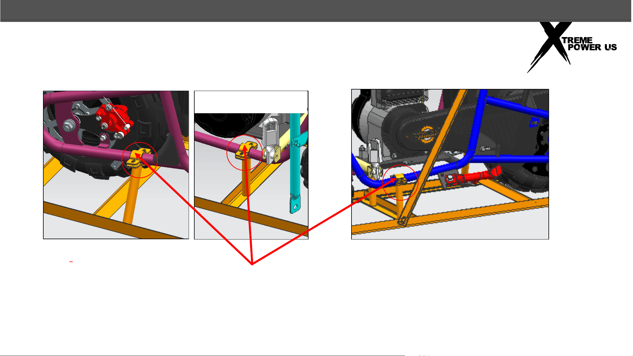
LEAVING THE BIKE ATTACHED TO THESE THREE BRACKETS WILL MAKE THE FRONT FORK AND FRONT WHEEL
ASSEMBLY MUCH EASIER. WHEN ASSEMBLY IS COMPLETE AND OIL HAS BEEN ADDED TO THE ENGINE, THEN YOU
CAN UNBOLT THE THREE BRACKETS AND REMOVE THE SHIPPING CRATE BASE AND DISCARD IT.
RIGHT SIDE OF BIKE NEAR REAR WHEEL
RIGHT SIDE OF BIKE NEAR THE
FOOTPEG
LEFT SIDE OF BIKE NEAR THE FOOTPEG
3
UNPACKING
NOTE:
ASSEMBLY
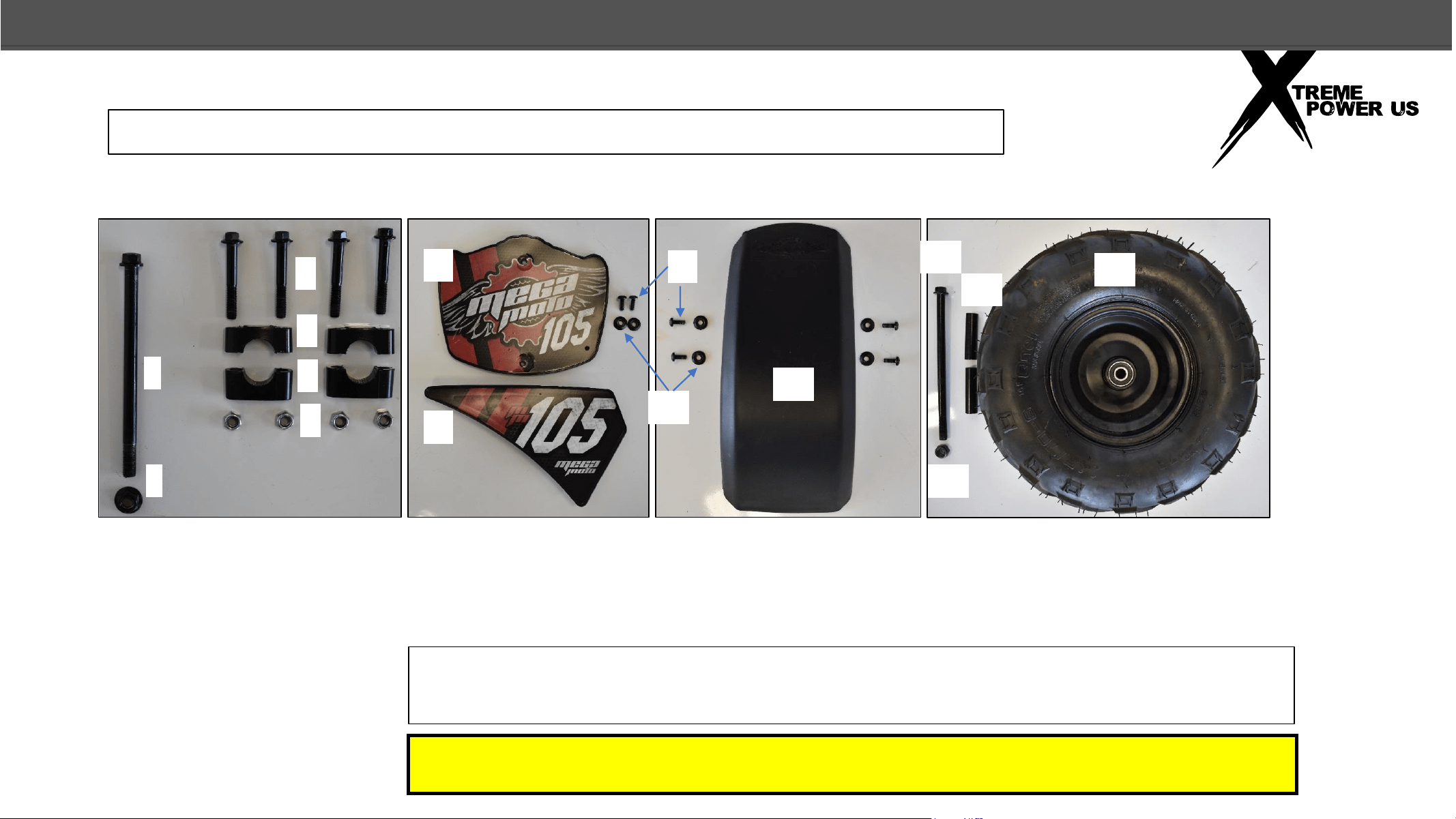
FRONT FORK AND HANDLEBAR HARDWARE
NUMBER PLATE AND RIGHT
GUSSETT
FRONT FENDER
FRONT WHEEL
1
2
3
4
5
6
7
8
9
10
11
12
13
14
15
1) STEERING PIVOT BOLT (1PC)
2) STEERING PIVOT NUT (1PC)
3) HANDLEBAR CLAMP BOLTS
(4PCS)
4) UPPER HANDLEBAR CLAMPS
(2PCS)
5) LOWER HANDLEBAR CLAMPS
(2PCS)
6) HANDLEBAR CLAMP NUTS
(4PCS)
7) FRONT NUMBER PLATE (1PC)
8) RIGHT GUSSET PLATE (1PC)
9) SCREWS (M6) (6PCS)
10) PLASTIC WASHERS (6PCS)
11) FRONT FENDER
12) AXLE BOLT (1PC)
13) AXLE NUT (1PC)
14) AXLE SPACER (2PCS)
15) FRONT WHEEL/TIRE ASSEMBLY (1PC)
4
NOTE: It is advisable to gather the parts as shown so they are easy to locate
during assembly.
Wear protective gloves and eyewear when working on your mini bike.
Oil is not provided with the mini bike. 12oz of 10W30 Motor Oil is needed.
PARTS INFORMATION
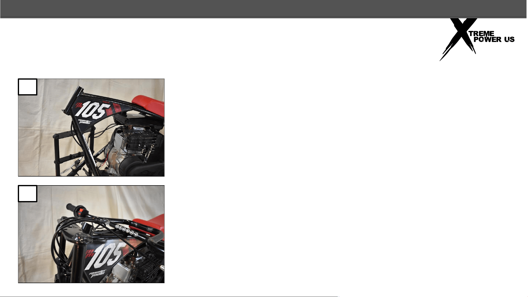
FRONT FORK
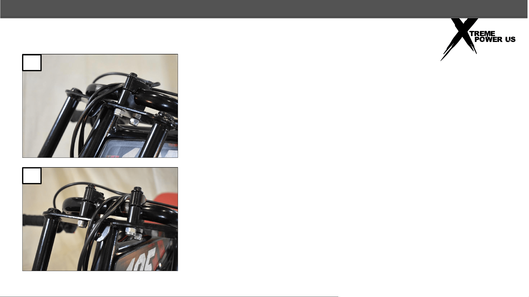
1. With the upper part of the steel shipping crate removed, the forks and
handlebar are resting on the right side of the bike. The bike should still be
attached to the base of the shipping crate.
2. Without twisting the wires and cables, lift up the handlebar and front fork
placing the handlebar on the top of the bike frame and resting the fork on
the steering head as shown in the photo. Rest the handlebar on the frame
with the handles toward the front of the bike, the brake lever should be
facing down. Make sure the wires and cables are not twisted.
5
2
1
ASSEMBLY
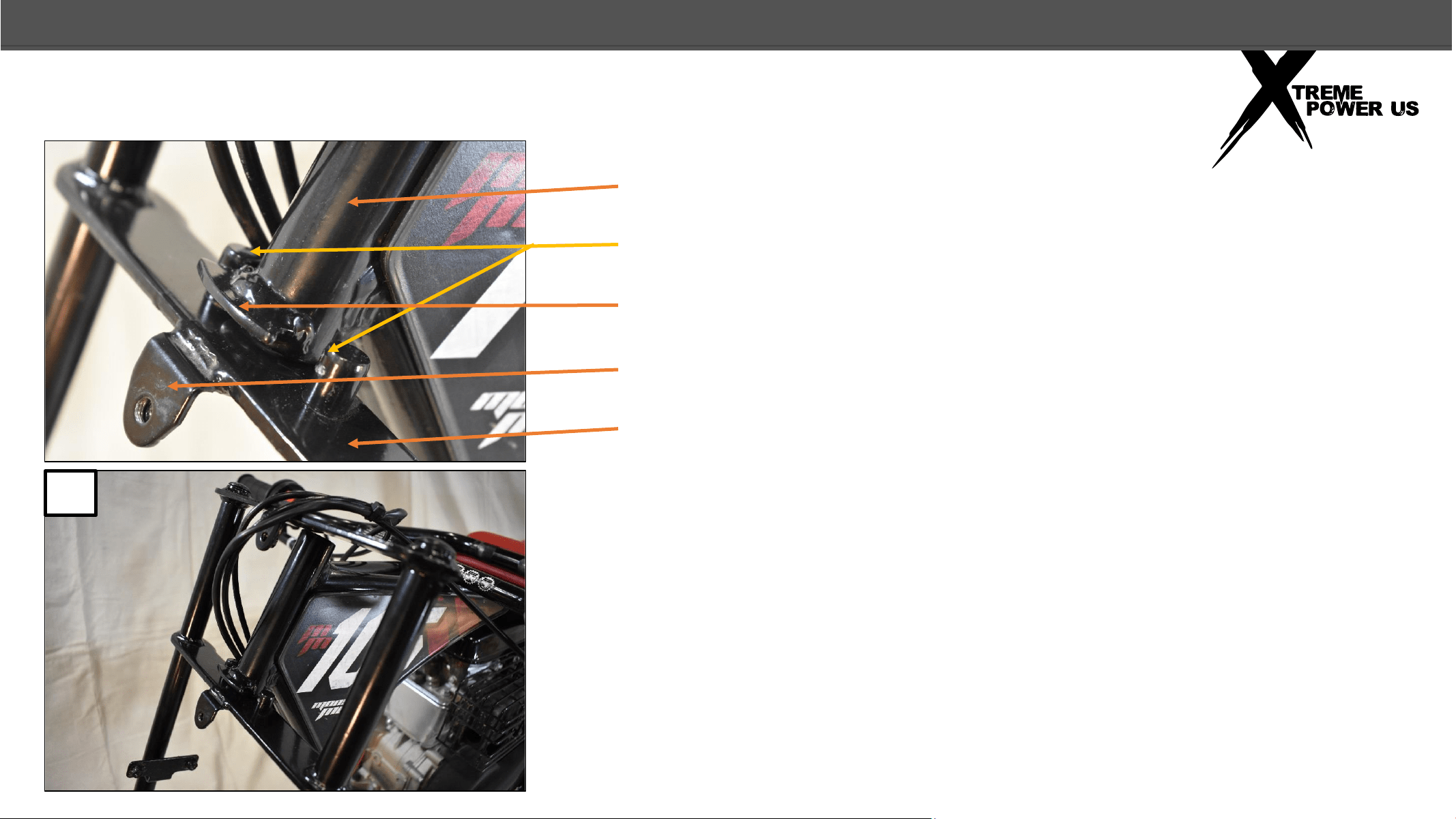
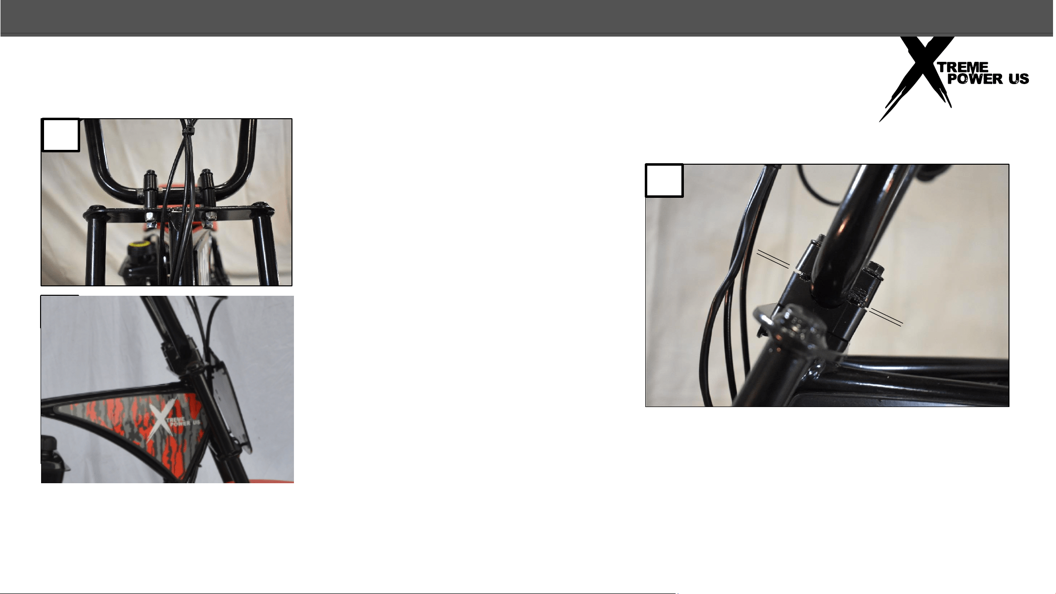
3. Make sure the number plate tabs on the forks are facing forward
and slide the lower fork plate under the steering head. Make sure
the steering stop pins are behind the steering stop as shown.
Steering Head
Steering stop pins
Steering stop
Number Plate Tab
Lower Fork Plate
6
FRONT FORK
3
ASSEMBLY
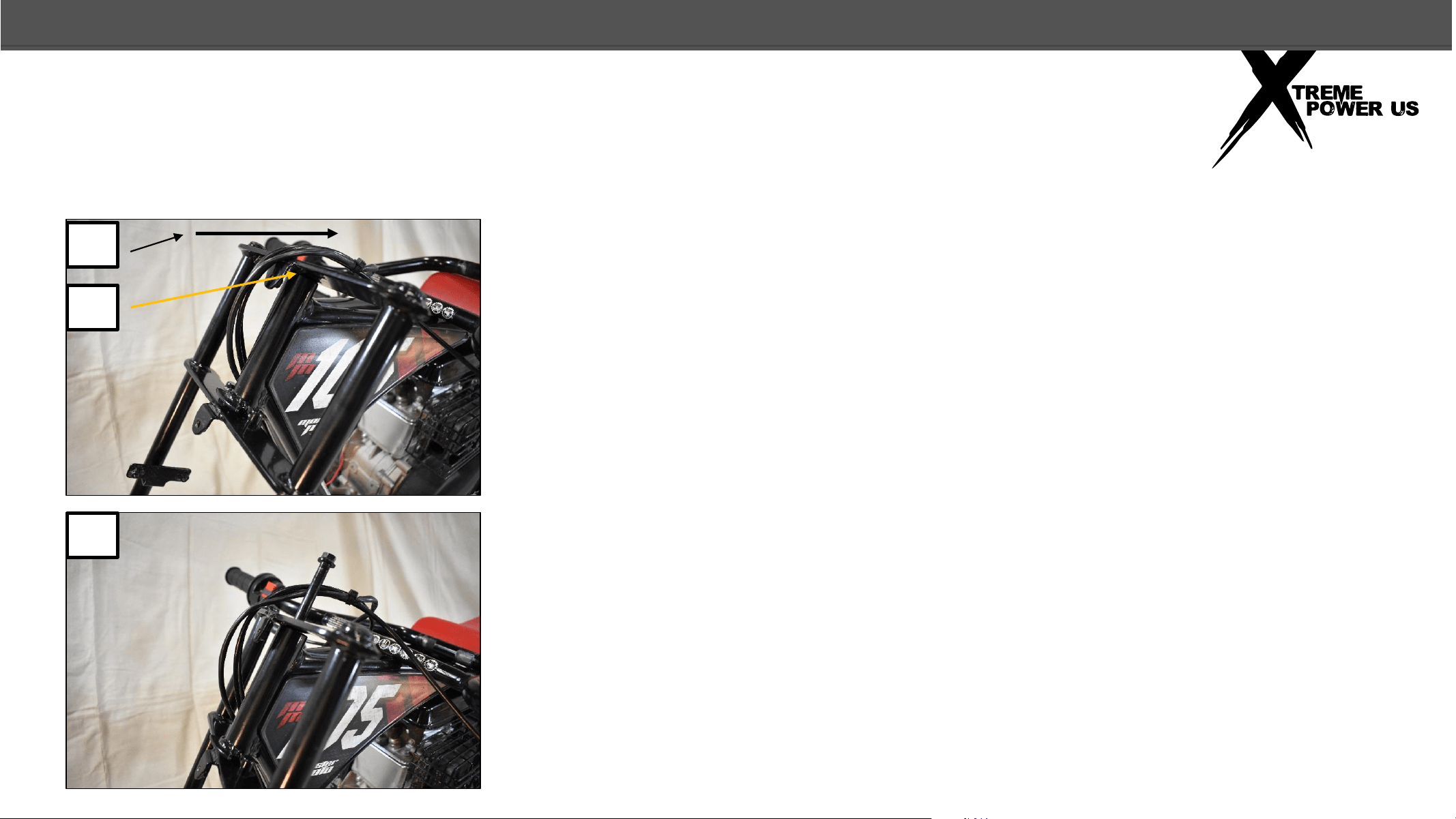
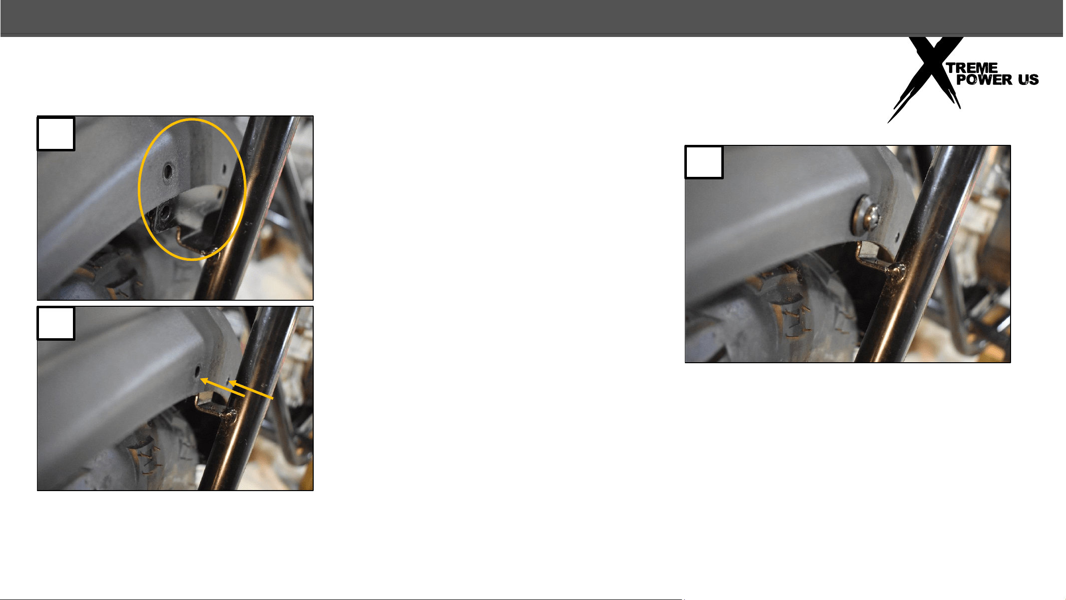
4. While keeping the steering stop pins behind the steering stop, move
the upper fork plate back and over the steering head.
5. Line up the hole in the upper fork plate with the hole in the steering
head.
7
6. Insert the steering bolt through the top fork plate and into the steering
head.
FRONT FORK
6
4
5
ASSEMBLY
8
7. Push the steering bolt all the way through the steering head and the lower
fork plate
8. Install the nut on the steering bolt as shown in the photo.
9. Tighten the nut securely, (39N.m/20ft.lbs.)
FRONT FORK
9
8
7
ASSEMBLY
9
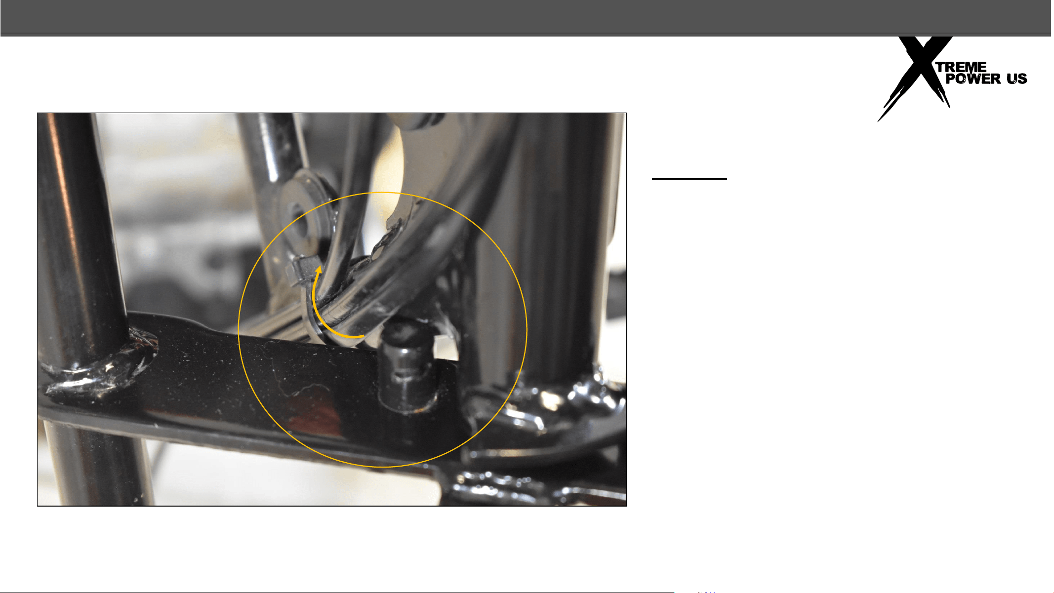
FRONT FORK
NOTE: Make sure the wires and cables do
not pinch between the frame and the lower
fork plate or the steering stop pin and the
frame when the handlebar is turned to the
right, (as seated on the bike). If they do,
simply twist the cable tie, wires, and cables
toward the rear, away from the lower fork
plate.
ASSEMBLY
10
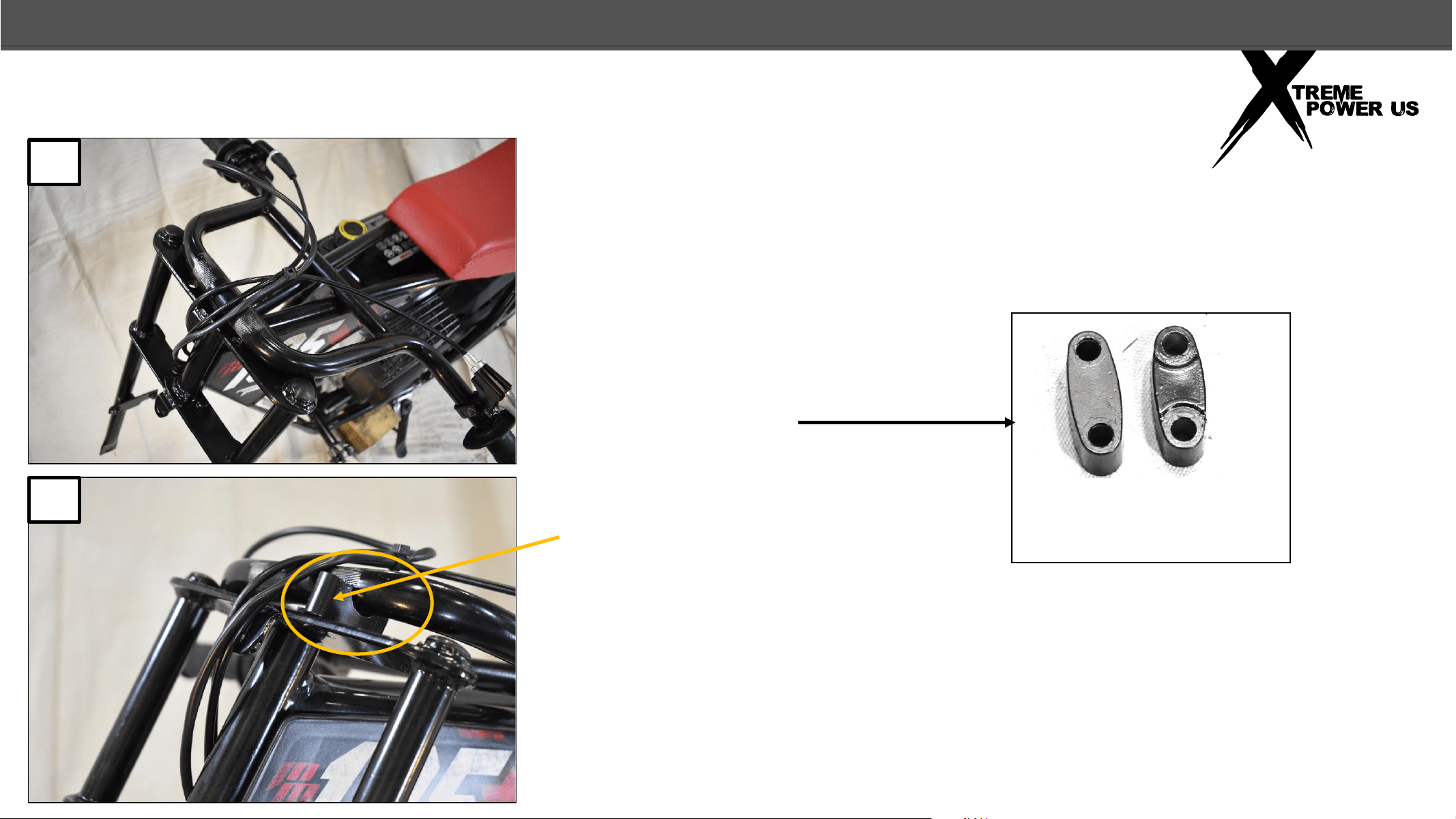
HANDLEBAR
10. Rotate the lower portion of the handlebar forward and
under the grips and lever portion of the handlebar and rest
the handlebar on the top fork plate and frame as shown. The
brake lever should be facing up and the cables should not be
twisted.
11. Locate the 2 upper and 2 lower
handlebar clamps.
Lower
Clamp
2pcs
Upper
Clamp
2pcs
12. Place one lower handlebar
clamp under the handlebar as
shown and align the holes in the
clamp with the holes in the upper
fork plate.
12
10
ASSEMBLY
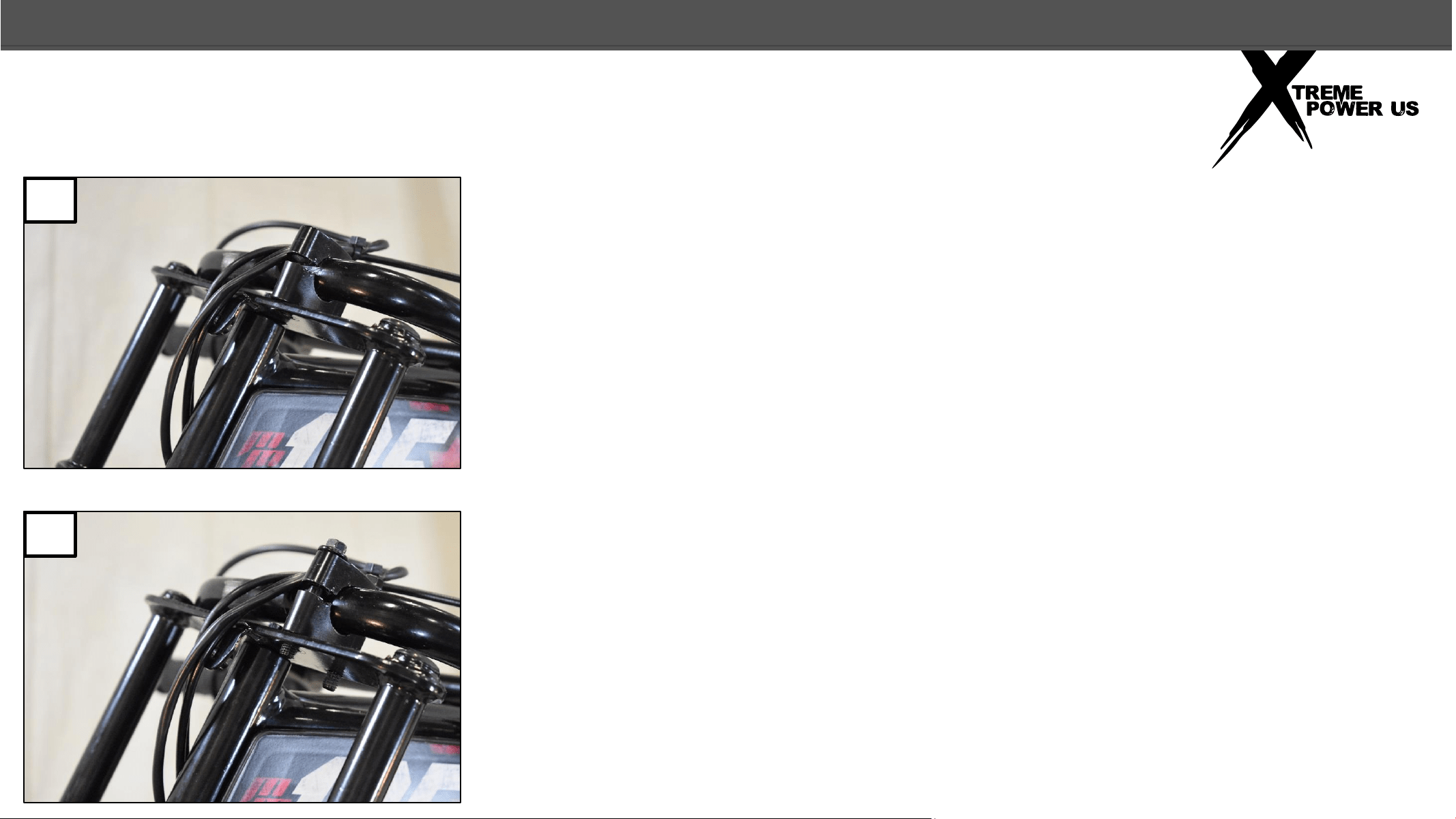
HANDLEBAR
11
13. Place the upper handlebar clamp as shown.
14. Insert the 2 handlebar clamp bolts through the holes in the upper
and lower clamps and the holes in the upper fork plate as shown.
14
13
ASSEMBLY
12
HANDLEBAR
15. Install the nuts on the handlebar clamp bolts as shown. Do Not tighten.
16. Install the clamps, bolts, and nuts on the other side (as in steps 12
through 15).
16
15
ASSEMBLY
13
HANDLEBAR
17. Center the handlebar on
the two clamps.
18. Angle the handlebar to
align with the angle of the
forks. This is a good initial
setting, you can adjust the
handlebars at a different
angle if you prefer.
19. Tighten the handlebar clamps so that
the space between the upper and lower
clamps at the front of the clamps is equal
to the space at the back of the clamps.
Tighten securely (26N.m/19ft.lbs.)
19
18
17
ASSEMBLY
14
FRONT FENDER
20. With the Mega Moto logo
facing forward, place the front
fender over the mounting brackets
on the front forks
21. Align the holes in the fender
with the threaded holes in the
mounting brackets.
22. Insert the Philips head screw through
the plastic washer, the fender and into
the threaded hole of the mounting
bracket and hand tighten. Have all 4
screws and washers installed by hand
before tightening with a screwdriver.
22
21
20
ASSEMBLY
15
FRONT WHEEL
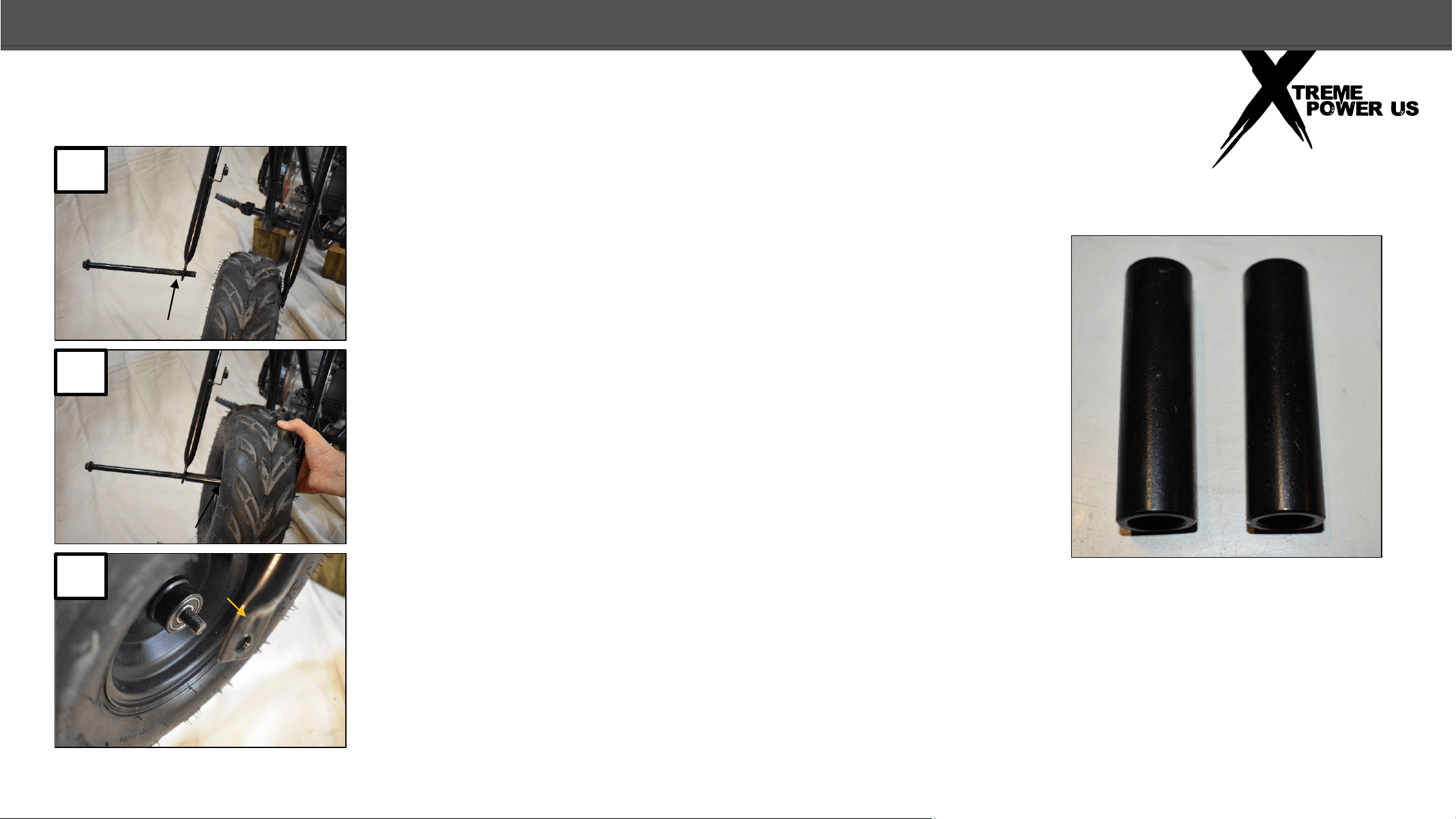
23. Insert the front axle bolt through the right fork, (as
seated on the bike), so that only an inch or 2 of the bolt
is through.
24. Place 1 axle spacer on the bolt, position the wheel
between the forks with the tread as shown, and insert
the axle bolt through the wheel.
25. Push the axle bolt through the other side of the
wheel so that only about an inch of it extends past the
wheel bearing.
Axle spacers
25
24
23
ASSEMBLY
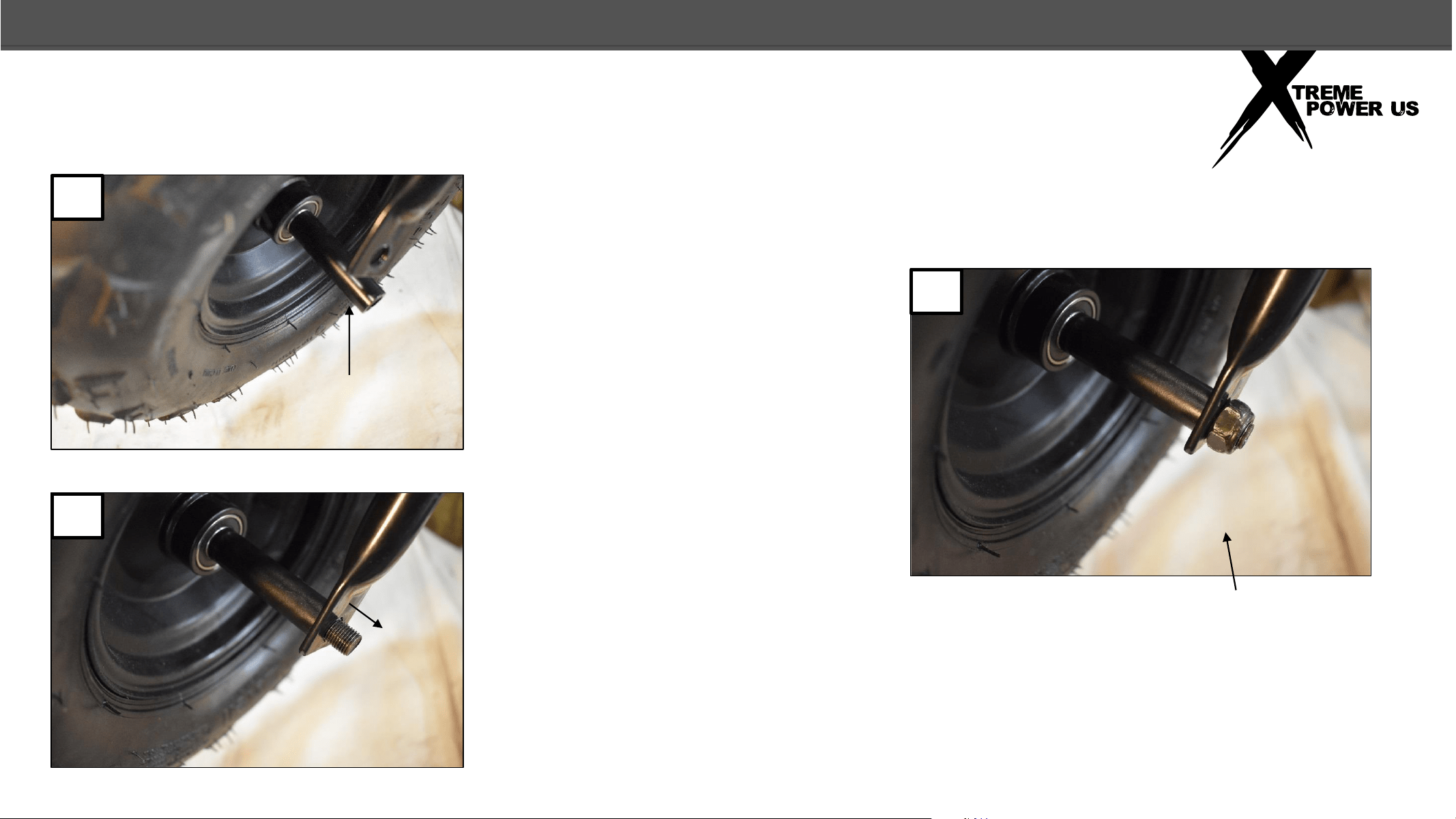
16
FRONT WHEEL
26. Place the second axle spacer
on the axle where it extends from
the wheel.
27. Align the spacer and the hole
in the fork and push the axle bolt
all the way through.
28. Install the nut on the axle and
tighten securely. (54N.m/40ft.lbs.)
28
27
26
ASSEMBLY
17
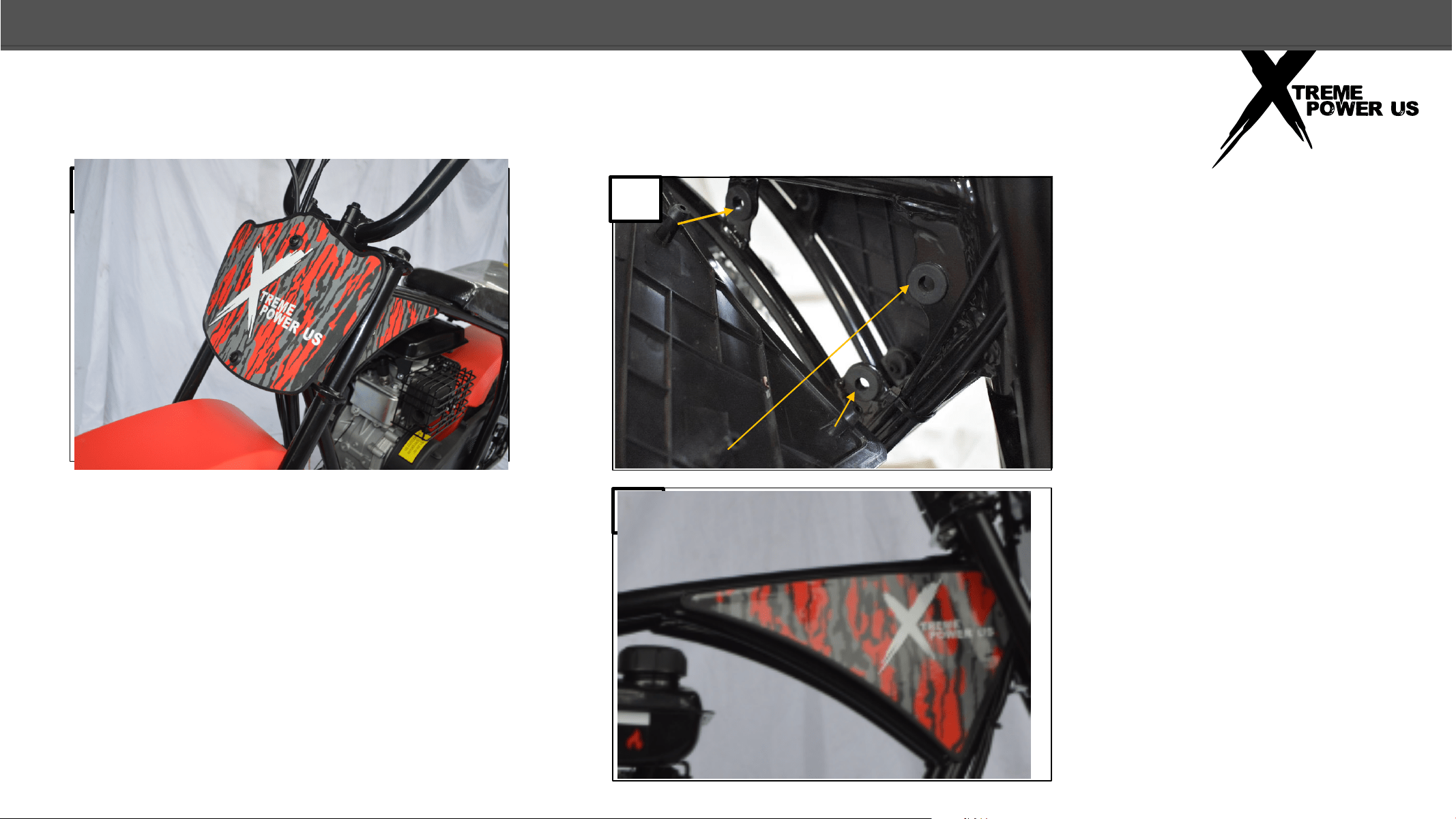
FRONT NUMBER PLATE AND GUSSET COVER
29. Place the number plate over the
number plate tabs on the front fork,
align the holes in the number plate
with the threaded holes of the tabs
and insert a screw with a plastic
washer through the top hole and hand
tighten. Install the screw and washer
in the lower hole. Tighten the upper
and lower screws with a screwdriver
30. Align the tabs on the right
side gusset cover with the
rubber mounting holes in the
frame.
31. Press the gusset cover
tabs into the rubber mounting
holes.
NOTE: Keep the bike
secured to the steel crate
base when you proceed to
the next step of adding oil
to the engine
31
30
29
ASSEMBLY
18
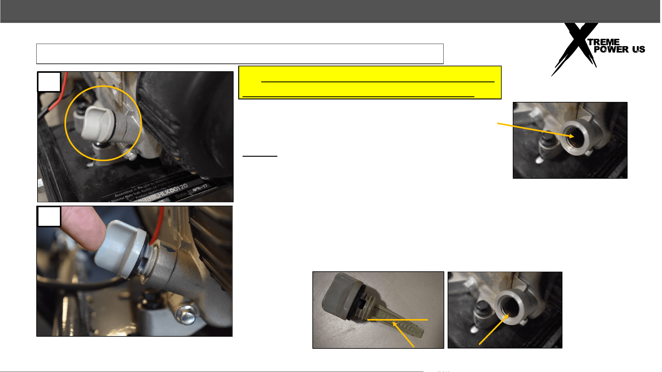
ADDING OIL
32. BEFORE YOU START THE BIKE YOU MUST ADD
12oz. OF 10W30 MOTOR OIL TO THE ENGINE.
The bike should be on the steel shipping crate base
so that it is vertical. Add oil into the oil filler neck
on the front of the engine.
NOTE: Whenever checking the engine oil level, the
bike should be on level ground and held vertical on
its two wheels, not resting on the side stand as the
proper oil level will not be indicated on the dipstick.
33. After adding oil, place the dipstick squarely in the filler hole but do not
screw it in. Pull out the dipstick and see where the oil level is on the
dipstick. Add as needed. Replace the dipstick and tighten .
Proper Oil Level
Oil is not provided with the mini bike. 12oz of 10W30 Motor Oil is needed.
32
33
ASSEMBLY
19
WEAR PROTECTIVE GLOVES
34. Unbolt the 3 clamps that secure the mini bike to the steel crate base, roll the bike off the base and discard
the base.
ADDING OIL
ASSEMBLY
20
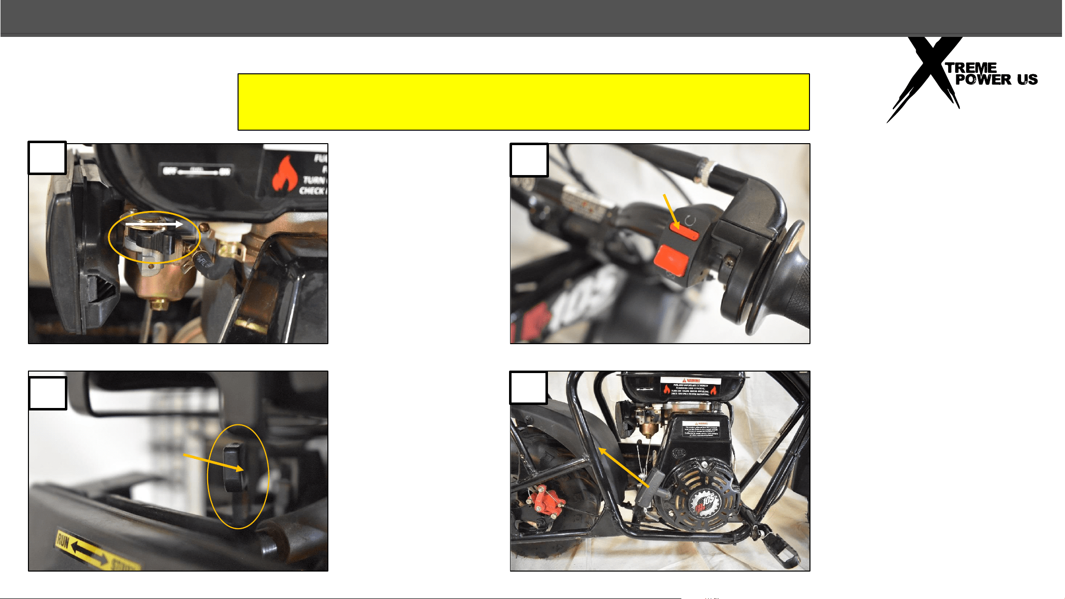
STARTING THE MINI BIKE
35. After adding
fuel to the fuel
tank, push the fuel
lever forward to
start fuel flow into
the carburetor
36. Move the
choke lever to the
right, “START”
position.
37. Press small red
button on the Engine
Stop Switch so that the
small button is pushed
in and the larger red
button sticks out. This is
the “RUN” position.
38. Let the bike sit for a
minute to give time for
the fuel to fill the
carburetor, then pull
firmly on the pull starter
to start the bike.
BE SURE TO OIL THE CENTRIFUGAL CLUTCH BEFORE AND AFTER
EACH RIDE AS INSTRUCTED IN YOUR OWNER’S MANUAL.
38
37
35
36
OPERATION
21
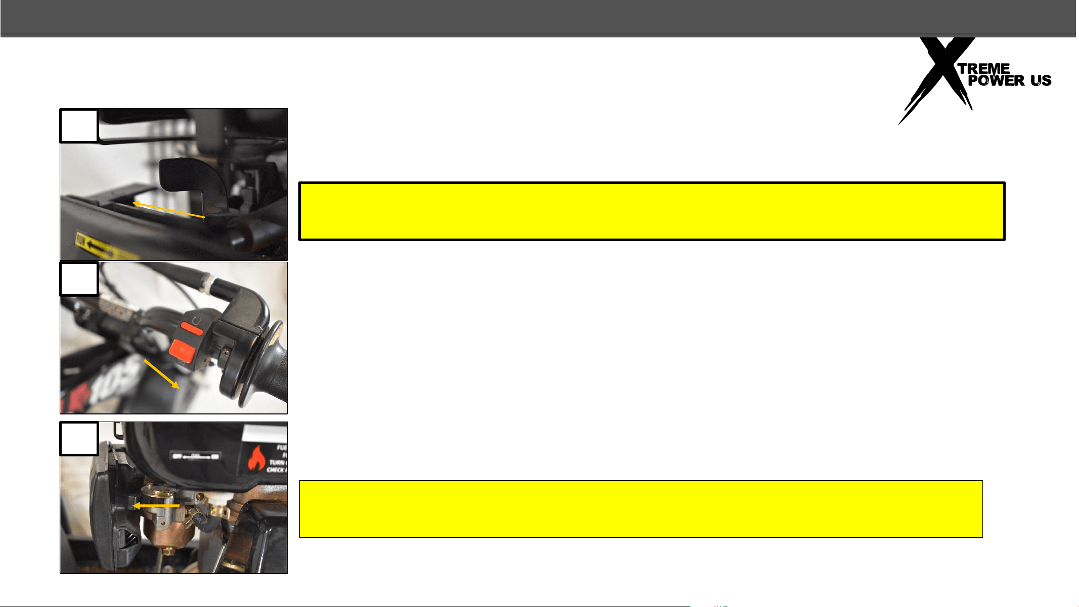
STARTING THE MINIBIKE
39. After the bike has started and has had a
minute or two to warm up, push the choke lever
to the left, “RUN” position.
40. To turn off the bike push the large red
button on the Engine Stop Switch.
41. When you are done riding the mini bike,
turn the Fuel Lever to the “OFF” position.
BE SURE TO OIL THE CENTRIFUGAL CLUTCH BEFORE AND AFTER EACH RIDE AS
INSTRUCTED IN YOUR OWNER’S MANUAL.
ALWAYS WEAR PROTECTIVE GEAR SUCH AS A HELMET, GLOVES, BOOTS, LONG
SLEEVE SHIRT, AND PANTS WHEN RIDING.
39
40
41
OPERATION
THE MANUFACTURER AND/OR DISTRIBUTOR HAS PROVIDED THE PARTS LIST AND ASSEMBLY DIAGRAM IN THIS MANUAL AS A REFERENCE TOOL ONLY.
NEITHER THE MANUFACTURER OR DISTRIBUTOR MAKES ANY REPRESENTATION OR WARRANTY OF ANY KIND TO THE BUYER THAT HE OR SHE IS QUALIFIED
TO MAKE ANY REPAIRS TO THE PRODUCT, OR THAT HE OR SHE IS QUALIFIED TO REPLACE ANY PARTS OF THE PRODUCT. IN FACT, THE MANUFACTURER AND/
OR DISTRIBUTOR EXPRESSLY STATES THAT ALL REPAIRS AND PARTS REPLACEMENTS SHOULD BE UNDERTAKEN BY CERTIFIED AND LICENSED TECHNICIANS,
AND NOT BY THE BUYER. THE BUYER ASSUMES ALL RISK AND LIABILITY ARISING OUT OF HIS OR HER REPAIRS TO THE ORIGINAL PRODUCT OR REPLACEMENT
PARTS THERETO, OR ARISING OUT OF HIS OR HER INSTALLATION OF REPLACEMENT PARTS THERETO.
DISCLAIMER