Installation and Operation Manual
Single Zone 115 VOLT FAHSW09A1C, FAHSW12A1C,
Single Zone 230 VOLT FAHSW36A3D
Single Zone & 208/230 VOLT FAHFW09A3D, FAHFW12A3D
Multi-Zone FAHFW18A3D, FAHFW24A3D,
Multi-Zone 208/230 VOLT FAHMW07A3D
Models
Ductless Split
Indoor Wall-Mounted Unit
R-32, R-454B Refrigerant
96111102_00
2
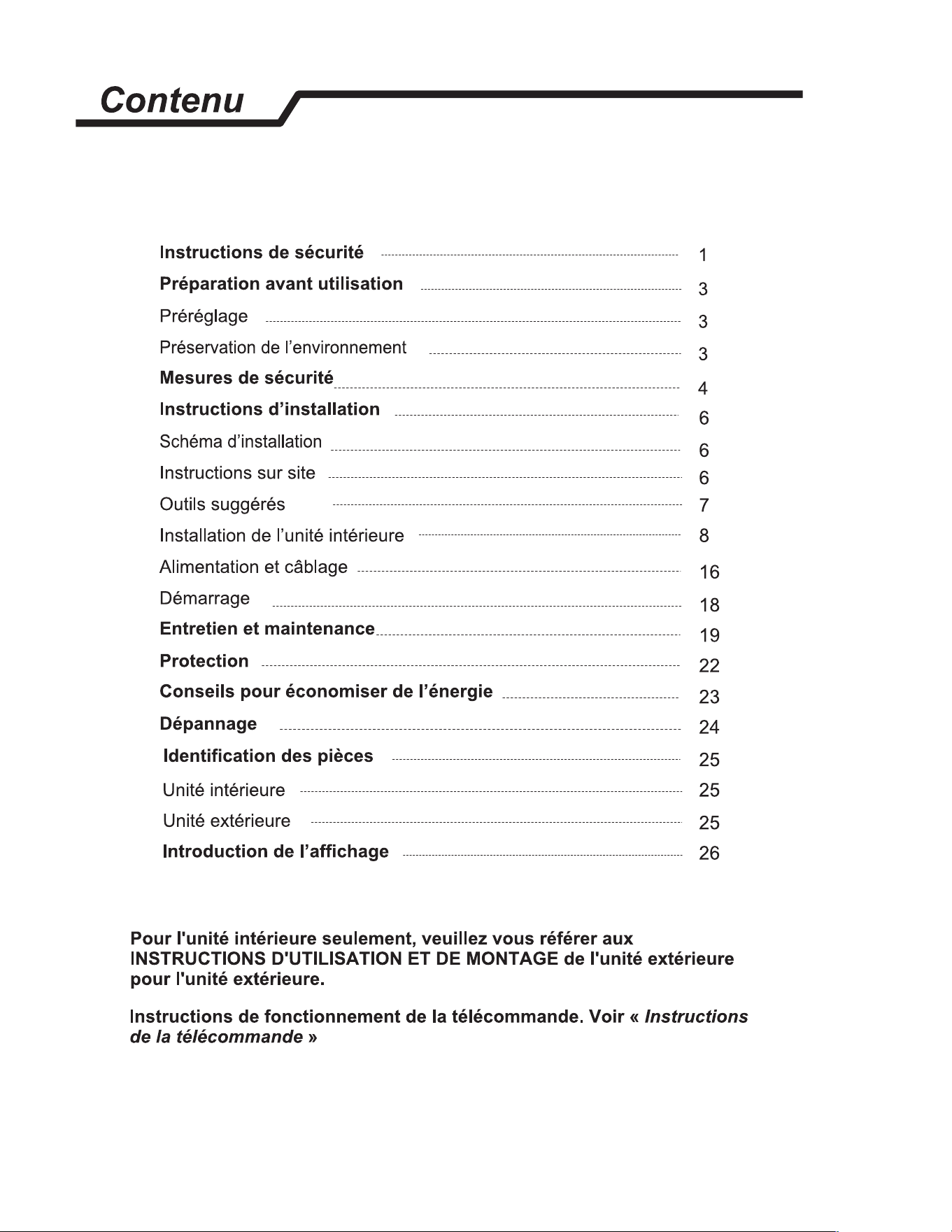
A. IMPORTANT SAFETY AND GENERAL INFORMATION ................. 3
A.1 Introduction ............................................................................. 3
A.2 • Safety Symbols ..................................................................... 3
A.4 Importance of a Quality Installation ..................................... 5
C. INSTALLATION OF THE UNIT ............................................................. 6
C.1 A2L Room size Restriction ..................................................... 6
C.2 Clearances .............................................................................. 6
C.3 Pre-Installation Checkpoints ................................................. 7
C.4 Install Mounting Plate ............................................................ 8
C.5 Drill Hole for Piping .............................................................. 10
C.6 Piping Provisions .................................................................. 11
C.7 Indoor Unit Installation ........................................................ 12
E. ELECTRICAL ........................................................................................ 16
E.1 Indoor Unit Wiring Connection Diagram ............................17
J. STARTUP AND OPERATION ..............................................................18
J.1 Checklist and Operation Test ...............................................18
ESPANOL .................................................................................................. 19
FRANÇAIS ................................................................................................49
Register your Air Conditioner
Model information can be found on the name plate.
Please complete and mail the owner registration card furnished with
this product, or register online at www.friedrich.com.
For indoor unit only, refer to the outdoor unit Installation
and Operation Manual as well as the Remote Control
Operation instructions for additional information.
NOTICE: This Indoor unit is compatible with both R-32 and
R-454B refrigerant. Prior to Installing the unit or servicing
the unit with refrigerant;
• Check the Outdoor unit being connected to for
refrigerant charge and type. Refer to the nameplate on
the outdoor unit.
• Ensure the unit meets the room size restriction for A2L
refrigerants. Refer to table C.1.
• Upon confirmation of the refrigerant type (from the
outdoor unit), the installing contractor should indicate
the system refrigerant type on the indoor unit by
marking the appropriate refrigerant indicator on the
indoor unit nameplate
US
C
tection I
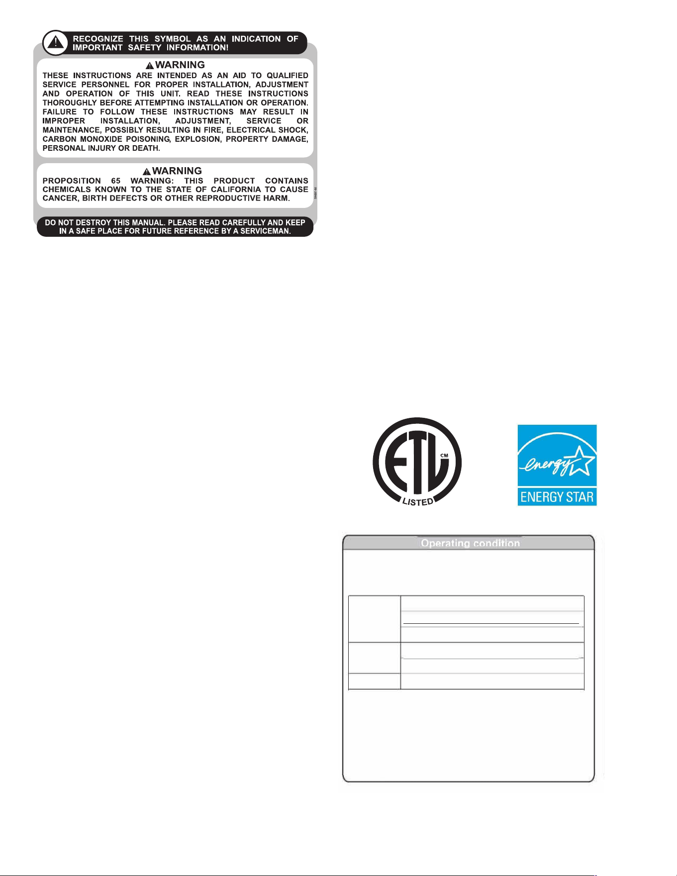
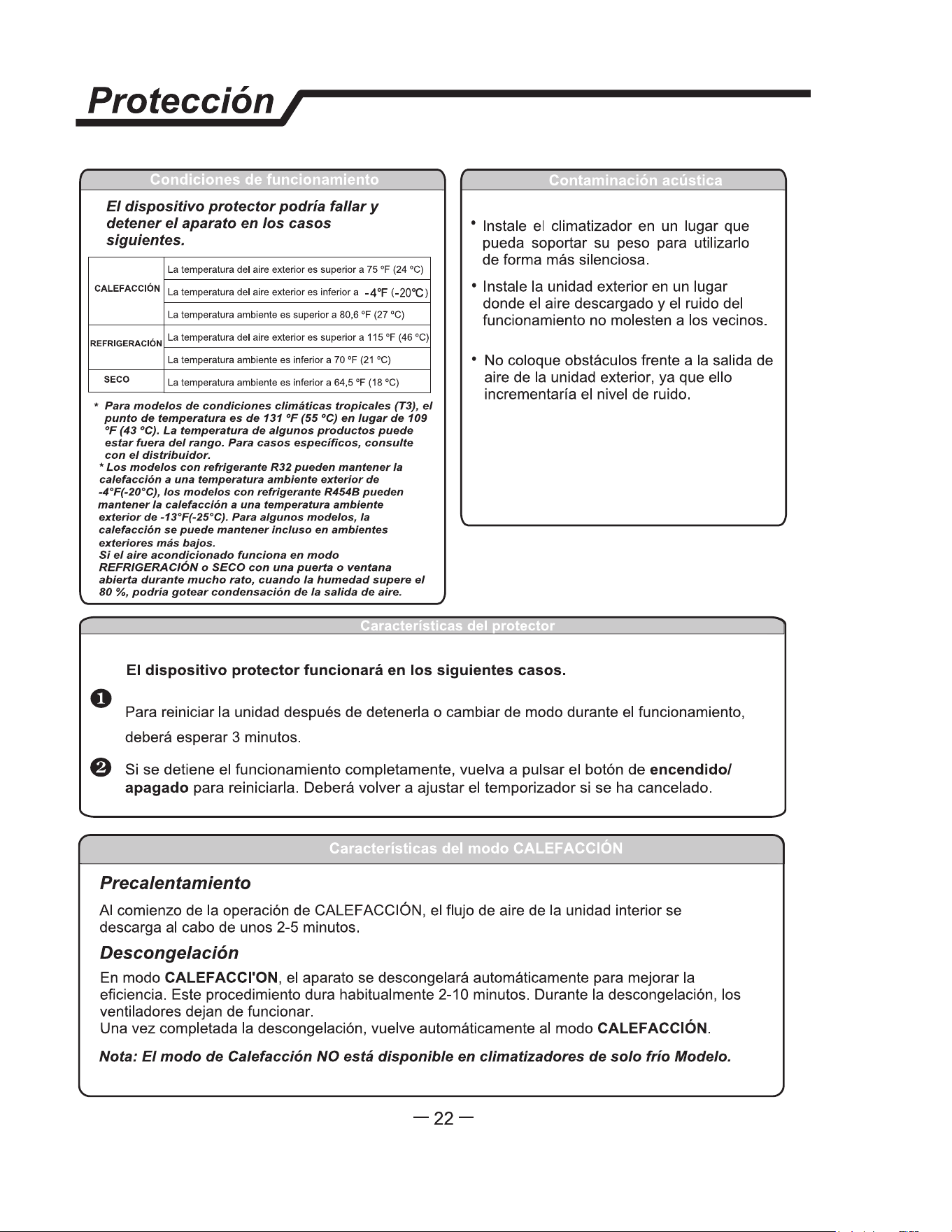
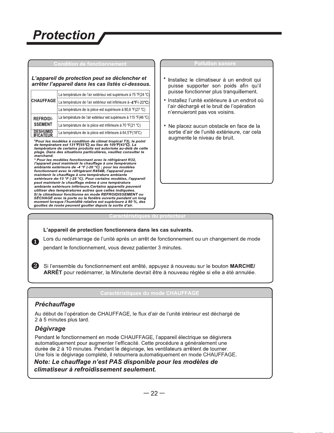
The ptecti dee mae tp and stop
e appance the cases listed below.
Outdoor air temperature is over 75
°
F(24
°
C)
HE
ING
Outdoor air tempetu is below -4
°
F(-
2
)
Room temperature is over 80.6
°
F(27
°
C)
COOLING
Outdoor air tempeture is over *115
°
F(46
°
C)
Room temperature is below 70
°
F(21
°
C)
DRY
Room temperature is below 64.5
°
F(18
°
C)
*r Tpical ) Clima conon models, e
tempetu pot is 131"F(55"C) sad of 109"F(43"C).
The mpetu of some pduc is aod bend the
nge. In specic situation, please consult e mehant.
*For R32 erant mode can keep heang at -4
°
F(-20 °C)
outdoor ambient, r R eerant mols n ke
heating at -13
°
F (-25 "C) outdoor ambient. For some mode,
can keep heating even at lower outdoor ambient
e air condioner ns COOUNG or DRY mode
door or dow opened r a long me en la
humidi abo 8,dew may dp do m e ouet.
•
Install the air conditioner at a place that
can bear its weight in order to operate
more quietly.
• Install the outdoor unit at a place where
the air discharged and the operation noise
would not annoy your neighbors.
• Do not place any obstacles in front of the
air outlet of the outdoor unit lest it increases
the noise level.
The protective device will work at following cases.
0 Restaing the unit at once after operation stops or changing mode during operation, you need to
wait 3 minutes.
If all operation has stopped, press ON/OFFbutton again to resta, Timer should be set again
if it has been canceled.
Preheat
At the beginning of the HEING operation, the ailow from the indoor unit is discharged
2-5 minutes later.
Dest
In HE
ING operation the appliance will defrost (de-ice) automatically to raise eiciency.
This procedure usually lasts 2-10 minutes. During defrosting, fans stop operation.
After defrosting completes, it returns to HEATING mode automatically.
-18-
3
A. IMPORTANT SAFETY AND GENERAL INFORMATION
A.1 Introduction
This booklet contains the installation and operating instructions for your Air Conditioning unit. There are some precautions that should be taken
to ensure proper operation. Improper installation can result in unsatisfactory operation or dangerous conditions.
Read this booklet and any instructions packaged with separate equipment required to make up the system prior to installation. Give this booklet
to the owner and explain its provisions. The owner should retain this booklet for future reference.
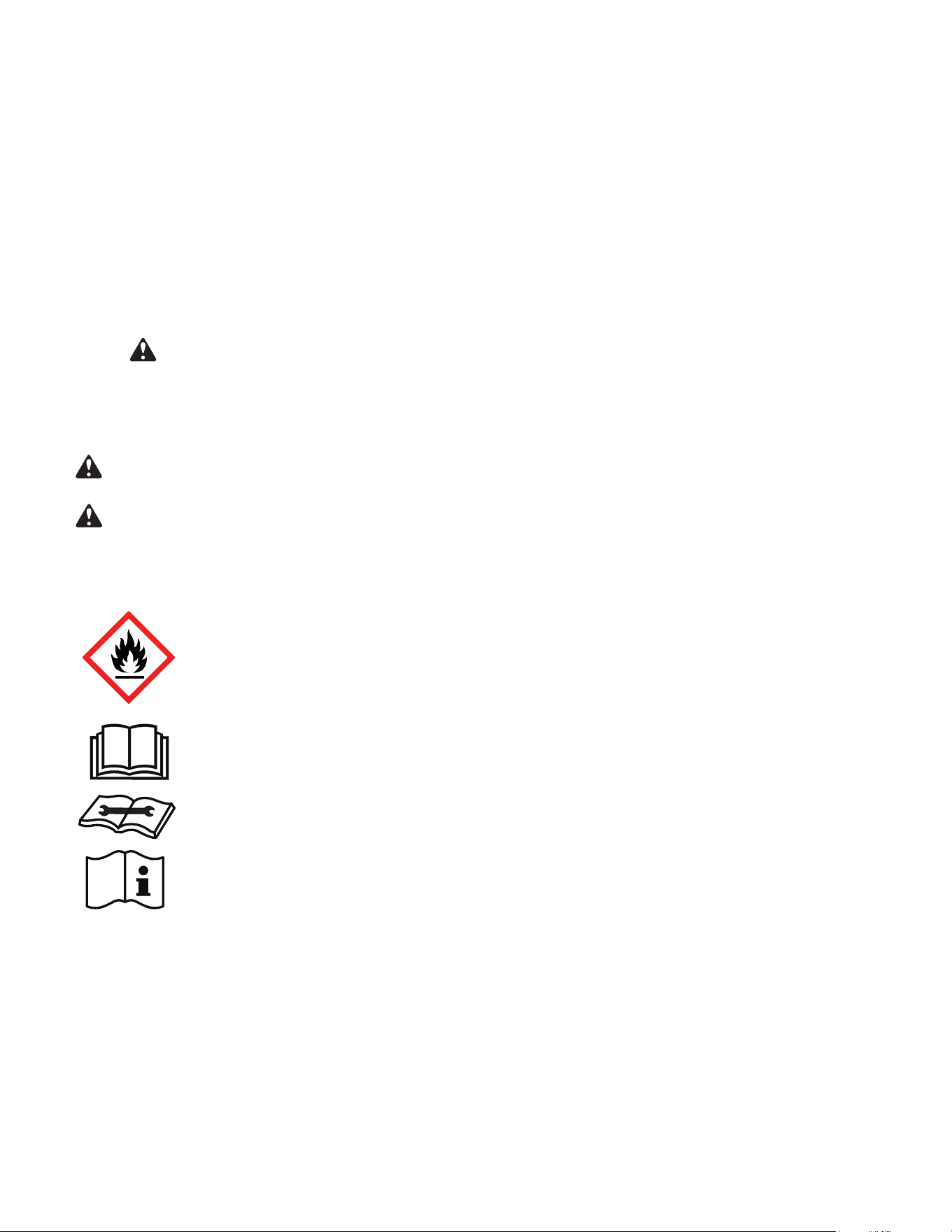
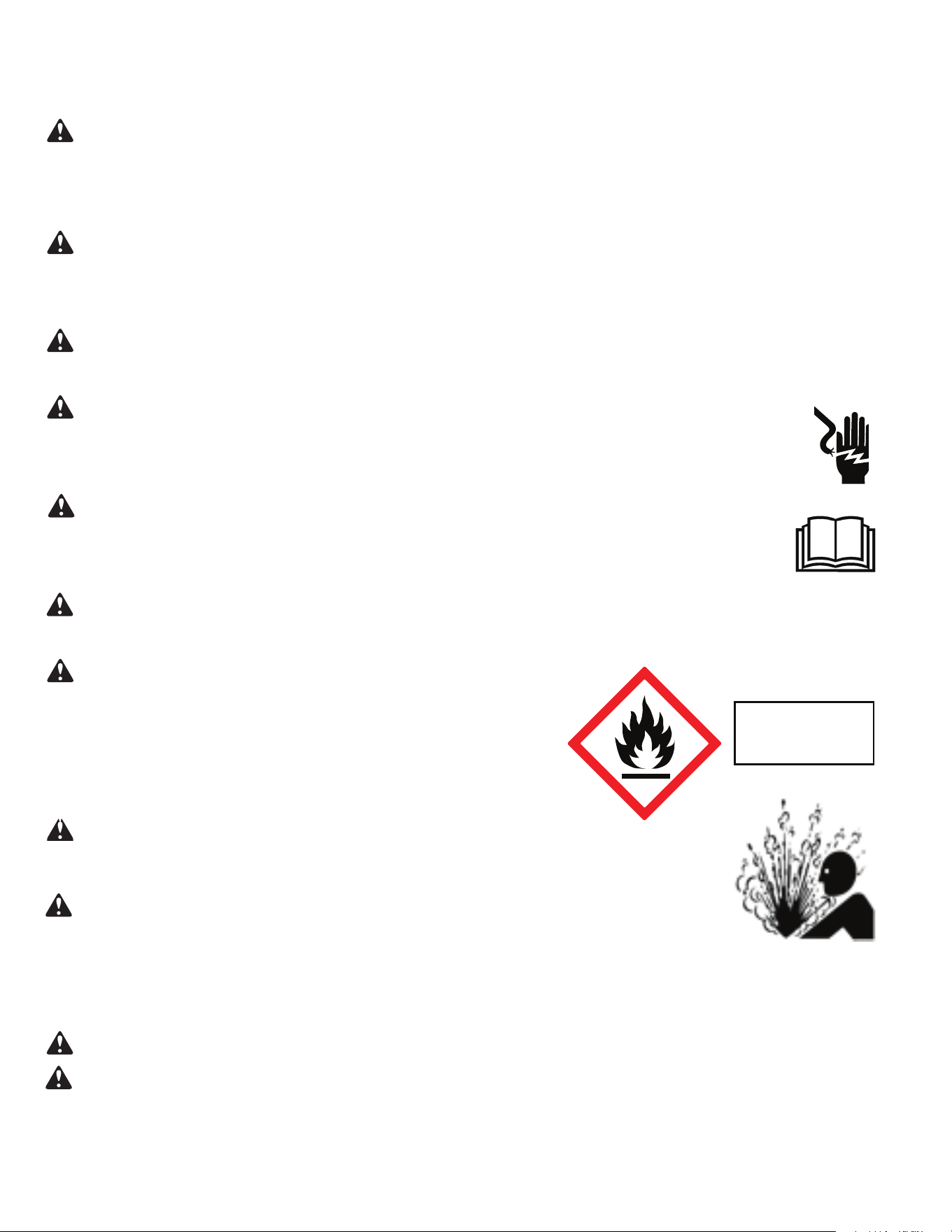
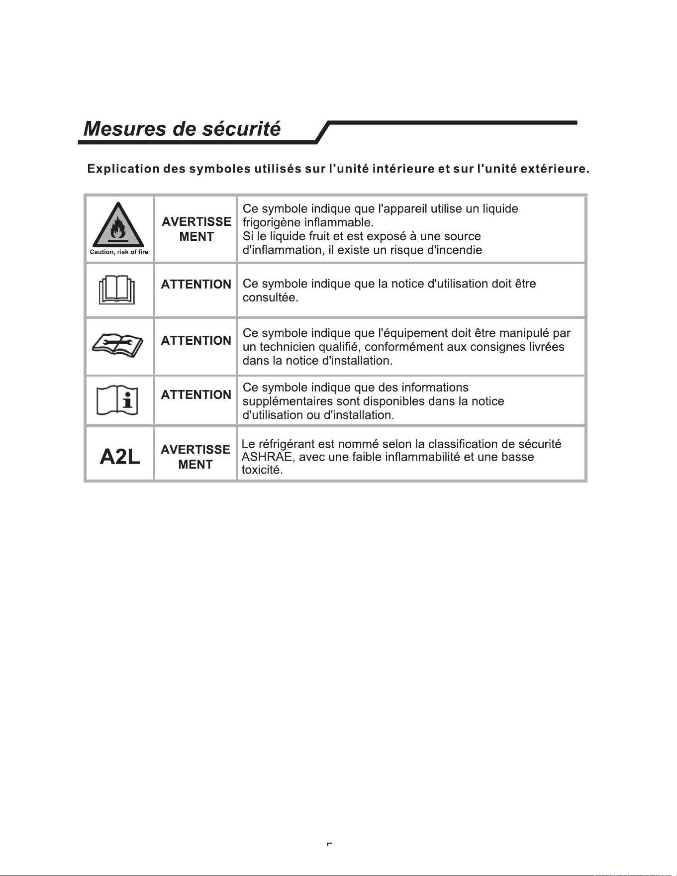
A.2 • Safety Symbols
This symbol indicates that this appliance uses a flammable refrigerant. If the refrigerant is leaked and is exposed to an
external ignition source, there is a risk of fire.
This symbol indicates that the Operation Manual should be read carefully.
This symbol indicates that service personnel should be handling this equipment with reference to the installation manual.
This symbol indicates that information is available such as the Installation and Operation manual, or the Service Manual.
SAFETY IS IMPORTANT
We have provided many important safety messages in this manual and on your appliance. Always read and obey all safety messages.
Indicates a hazard which, if not avoided, can result in severe personal injury or death and damage to product or other
property.
Indicates a hazard which, if not avoided, can result in personal injury and damage to product or other property.
All safety messages will tell you what the potential hazard is, tell you how to reduce the chance of injury, and tell you
what will happen if the instructions are not followed.
NOTICE
CAUTION
WARNING
All safety messages will follow the safety alert symbol with the word “WARNING” or “CAUTION”. These words mean:
This is a safety Alert symbol. This symbol alerts you to potential hazards that can kill or hurt you and others.
Indicates property damage can occur if instructions are not followed.
4
A. IMPORTANT SAFETY AND GENERAL INFORMATION
A.3 • Safety Warnings
WARNING
:
The manufacturer’s warranty does not cover any damage or defect to the air conditioner caused by the attachment
or
use of any components, accessories or devices (other than those authorized by the manufacturer) into, onto or in conjunction with the air
conditioner. You should be aware that the use of unauthorized components, accessories or devices may adversely affect the operation of the
air conditioner and may also endanger life and property. The manufacturer disclaims any responsibility for such loss or injury resulting from
the use of such unauthorized components, accessories or devices.
WARNING
:
This appliance is not intended for use by persons (Including children) with reduced physical, sensory or mental
capabilities, or lack of experience and knowledge, unless they have been given supervision or instruction concerning use of the appliance by
a person responsible for their safety.
Children should be supervised to ensure that they do not play with the appliance.
WARNING
:
The maximum altitude for this appliance is 2,000 meters(6,562 feet).
Do not use above 2,000 meters(6,562 feet).
WARNING: Electrical Shock Hazard
Disconnect all power to the unit before starting maintenance. All electrical connections and wiring MUST be installed by a qualified
electrician and conform to all local codes which have jurisdiction. Failure to do so can result in property damage, severe electrical
shock or death.
WARNING:
Read Installation Manual
Read this manual thoroughly prior to equipment installation or operation. It is the installer’s resposibility to properly apply
and install the equipment. Installation must be in conformance with the NFPA 70-2023 national electric code or current edition,
International Mechanic code 2021 or current edition, and any other local or national codes.
WARNING:
Safety First
Do not remove, disable, or bypass this unit’s safety devices. Doing so may cause fire, injuries, or death.
WARNING: This Product uses R-32 or R-454B Refrigerant
Do not use means to accelerate the defrosting process or to clean, other than those
recommended by the manufacturer.
The appliance shall be stored in a room without continuously operating ignition sources
(for example: open flames, an operating gas appliance or an operating electric heater.
Do not pierce or burn.
Be aware that refrigerants may not contain an odor.
WARNING:
Refrigeration System under High pressure
Do not puncture, heat, expose to flame or incinerate. Only certified refrigeration technicians should service this
equipment. R454B systems operate at higher pressures than R22 equipment. Appropriate safe service and
handling practices must be used.
CAUTION:
Do Not Operate Equipment During Active Stages Of
Construction
To ensure proper operation, Friedrich requires that all equipment is not operated during active construction phases. This includes active stages
of completing framing, drywalling, spackling, sanding, painting, flooring, and moulding in the equipment’s designated conditioning space. The
use of this equipment during construction could result in premature failure of the components and/or system and is in violation of our standard
warranty guidelines. The opera
tion of newly installed equipment during construction will accelerate the commencement and/or termination of
the warranty period.
WARNING:
Keep all air circulation and ventilation openings free from obstruction.
WARNING:
The unit should not be in contact with any equipment that will transmit vibration to the unit. Any excessive vibration or
pulsation to the unit could result in damage to the refrigerant tubing.
Refrigerant
Safety Group
A2L
5
A. IMPORTANT SAFETY AND GENERAL INFORMATION
A.4 Importance of a Quality Installation
Optimal system performance and longevity depend upon a quality and proper installation. Failure to properly install this unit could result in
undesirable operation and subsequent faults and potential failures.
Carefully follow all guidelines listed in the manual and industry best practices. Conform to all local code requirements. Contact your local
technical representative with any questions or concerns.
Due to continuing research in new energy-saving technology, all information in this manual is subject to change without notice.
Upon receiving the unit, inspect it for any damage from shipment. Claims for damage, either shipping or concealed, should be filed immediately
with the shipping company. IMPORTANT: Check the unit model number, Cooling size, electrical characteristics, and accessories to determine if
they are correct.
WARNING:
Check the unit power cord and make sure the cord is protected from wear, corrosion, excessive pressure, vibration,
sharp edges, or any other adverse environmental effects. It is recommended that the cord is checked for any potential damage when filter
maintenance is performed. If the supply cord is damaged, it must be replaced by the manufacturer, its service agent or similarly qualified
persons in order to avoid a hazard.
WARNING:
If the unit appears damaged,or if a refrigerant leak is suspected, do not install.
Contact a licenced repair person to perform a leak check on the unit.
WARNING:
Under no circumstances shall potential sources of ignition be used in the searching
for or detection of refrigerant leaks. A halide torch (or any other detector using a naked flame) shall not be used. The following leak detection
methods are deemed acceptable for all refrigerant systems. Electronic leak detectors may be used to detect refrigerant leaks but, in
the case of FLAMMABLE REFRIGERANTS, the sensitivity may not be adequate, or may need re-calibration. (Detection equipment
shall be calibrated in a refrigerant-free area.) Ensure that the detector is not a potential source of ignition and is suitable for the refrigerant
used. Leak detection equipment shall be set at a percentage of the LFL.
WARNING:
Service of this product (aside from filter maintenance) shall only be performed by
trained service personnel. This includes:
• Opening of any ventilated Any tubing or refrigerant circuit work.
• Opening of any sealed components.
• Enclosures beyond the hinged door for filter cleaning.
• Disposal or decommissioning of the unit.
Scan this QR code to be linked to the Friedrich professional support page where you can locate the Service Manual.
6
C. INSTALLATION OF THE UNIT
Figure C.2
C.1 A2L Room size Restriction
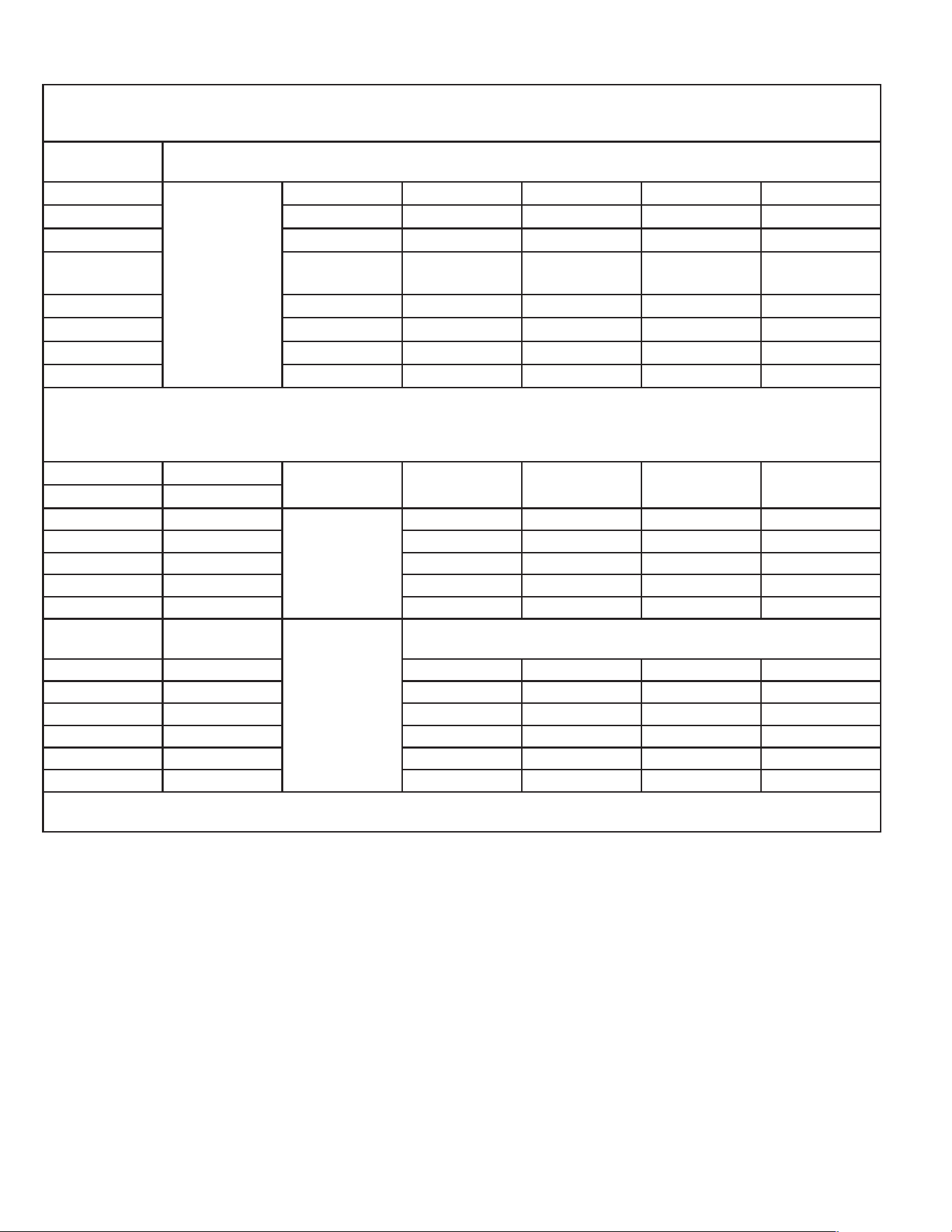
Minimum room size (R-32 or R-454B refrigerant) is determined by total refrigerant charge in system. Use this chart to determine the minimum room size the indoor head can be installed
in. 9 and 12k 208/230V indoor heads are capable off adding an optional accessory A2L sensor. This may be required in multi-zone applications See multi-zone Outdoor Unit IOM for
details and requirements.
Height of installation(ft and inches)
6’ 6' 6" 7' 2" 7' 10" 8' 2"
Refrigerant charge (oz) Room (sq ft)
64 oz. 71 64 58 53 51
65-71 oz. 78 71 64 59 57
72-77 oz. 86 78 71 65 62
78-85 oz. 94 85 77 71 68
86-92 oz. 102 92 83 77 74
93-99 oz. 110 99 90 82 79
100-106 oz. 117 105 96 88 85
Prior to installing the unit use the chart below to determine the total refrigerant charge for the unit. If the total charge is less than 64 oz. there is no room size restriction. If the total
charge is over 64 oz. refer to the chart above. Use the total charge, the height of the bottom of the unit, and the chart above to determine the minimum square footage of the room the
indoor unit can be installed in. If rooms are connected by opening that people can walk through but with no door installed, those areas can be considered one space.
Refrigerant Type
Pre-Charge w/ 25 ft of
line set
Charge w/ 25-50 ft of
line set
Charge w/ 50-75 ft of
line set
Charge- w/ add 75-100
ft of line set
Indoor Unit Model Outdoor Unit Model Charge Oz
FAHSW09A1C FSHSR09B1C
R-32
21.2 27.7 33.2 N/A
FAHSW12A1C FSHSR12B1C 21.9 27.4 32.9 N/A
FAHFW18A3D FSHSR18B3D 45.9 51.4 56.9 62.4
FAHFW24A3D FSHSR24B3D 47.7 55.7 63.7 71.7
FAHSW36A3D FSHSR36B3D 72.4 83.2 93.9 104.7
FAHMW07A3D Multi-Zone Only
R-454B
See Multi-Zone Outdoor Condenser IOM For details on Room size restriction and A2L sensor application
FAHSW09A1AC FPHSR09A1C 33.5 39 44.5 N/A
FAHFW09A3D FPHSR09A3D 35.3 40.8 46.3 N/A
FAHSW12A1C FPHSR12A1C 35.3 40.8 46.3 N/A
FAHFW12A3D FPHSR12A3D 38.1 43.6 49.1 N/A
FAHFW18A3D FPHSR18A3D 52.9 58.4 63.9 69.4
FAHFW24A3D FPHSR24A3D 70.6 78.6 86.6 94.6
When adding refrigerant to the system for additional line set, refer to the model nameplate and the outdoor unit installation instructions for proper charge amount.
Table C.1
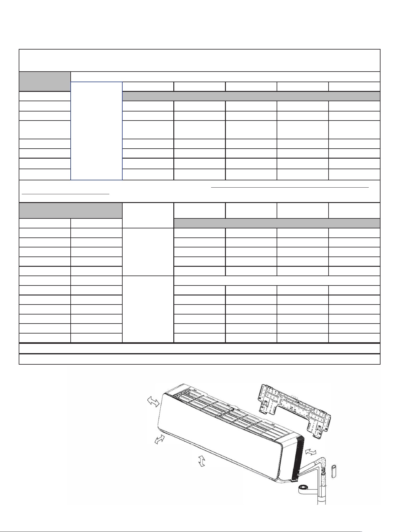
Installaon Insctions /
Installation diasram
Distance from wall
should be over 2in
Distance from the obstacle
should be over 9.8.
Distance from ceiling
should be over 7.9in
Distance from oor should
be over
6
ft.
Indoor unit A
Distance from the wall
should be over 2in
• Abo gu Is only a simple psentation of e uni It may not mah the eal appeance of the unit u puhased.
• Insation must be peed accoance wi the naonal ng sndas by auozed peonnel on.
Site Instructions
Si r Insng Indoor it
• 1. Where there is no obstacle near the air outlet and air can be
easily blown to every corner.
• 2. Where piping and wall hole can be easily arranged.
• 3. Keep the required space from the unit to the ceiling and wall
according to the installation diagram on previous page.
• 4. Where the air filter can be easily removed.
•
5. Keep the unit and remote controller 1 m(3.28) or more apart
from television, radio etc.
• 6. Keep as far as possible from fluorescent lamps.
•
7. Do not put anything near the air inlet to obstruct it from air
absorption.
• 8. Install on a wall that is strong enough to bear the weight of t
he unit.
N
E
s
C
_
-
.
�
Indoor unit
Pipe length is as follows:
For 15K and below1 SK:
20 mete 5.4) Max.
For 18K and above18K:
30 mete 8.4) Max.
Outdoor unit
•
9. Install in a place that will not increase operation noise and
vibration.
2�-----�
• 10. Keep away from direct sunlight and heating sources. Do not place
flammable materials or combustion apparatuses on top of the unit.
Indoor unit is higher than outdoor unit
staation of outdoor unit fe to the outdoor unit insation manual.
-5-
C.2 Clearances
7
C.3 Pre-Installation Checkpoints
1. Ensure there are no obstacles near the air outlet and air can be
easily blown to every corner.
2. Where piping and wall hole can be easily arranged.
3. Keep the required space from the unit to the ceiling and wall
according to the installation diagram on previous page.
4. Where the air filter can be easily removed.
5. Keep the unit and remote controller 3 ft or more apart from
television, radio etc.
6. Keep as far as possible from fluorescent lamps.
7. Do not put anything near the air inlet to obstruct it from air
absorption.
8. Install on a wall that is strong enough to bear the weight of t he
unit.
9. Install in a place that will not increase operation noise and
vibration.
10. Refer to Table C.3.3 for max line set length and max elevation.
11. Refer to the Outdoor Unit Installation and operation manual for
piping requirements, refrigerant charging, and operational checks.
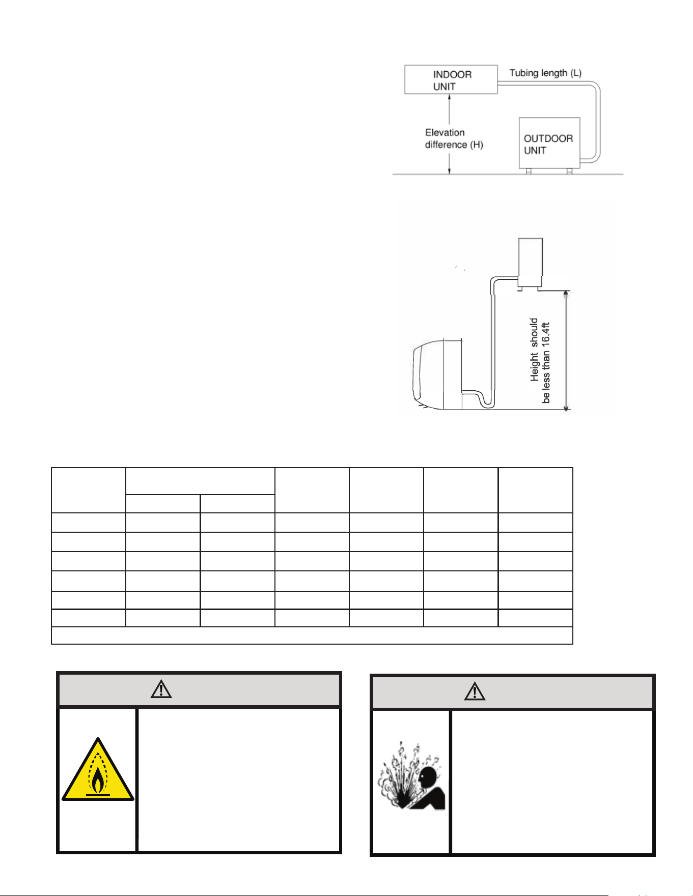
Capacity
(Btu/h)
Pipe Size
Standard
Length (ft)
Max.
Elevation
H (ft)
Max. Length
L (ft)
Additional
Refrigerant
(oz/ft)
LIQUID GAS
7k 1/4" 3/8" 25 50 66 .22
9k 1/4" 3/8" 25 50 66 .22
12k 1/4" 3/8" 25 50 66 .22
18k 1/4" 1/2" 25 50 100 .22
24k 3/8" 5/8" 25 50 100 .32
36K 3/8" 5/8" 25 50 100 .42
Table C.3.3
WARNING
Fire Hazard
A2L refrigerant is classified as mildly
flammable. Temperatures on surfaces that may
be exposed to leakage of FLAMMABLE
REFRIGERANTS shall not exceed 1292°F
WARNING
Refigeration System
Under High Pressure
Do not puncture, heat, expose to flame or
incinerate.
Only certified refrigeration technicians should
service this equipment.
R-32 and R-454B systems operate at higher
pressures than R22 equipment.
Appropriate safe service and handling
practices must be used.
Only use gauge sets designed for use with
R32 and R-454B.
Do not use standard R22 gauge sets..
/
Site Instructions
Site for Outdoor Unit
• Where it is convenient to install and well ventilated.
• Avoid it where ammable gas could leak.
•
Keep the required distance apart from the wall.
• Keep the outdoor unit away from greasy dirt, vulcanization gas exit.
•
Avoid installing it by the roadside where there is a risk of muddy
water.
•
A xed base where it is not subject to increased operation noise.
• Where there is not any blockage of the air outlet.
• Avoid installing under direct sunlight, in an aisle or sideway,
or near heat sources and ventilation fans. Keep away from
ammable materials, thick oil
and wet or uneven places.
Indoor unit
Outdoor unit
Outdoor unit is higher than indoor unit
• In case the pipe length is more than the refrigerant should be charged additionally, according
to below table.
Model
Required amount of
additional refrigerant (Oz)
9K-18K
0.7
24K
1.0
If the height or pipe length is out of the scope of the table, please consult the merchant.
of indoor unit refers to indoor unit manual.
-7-
Figure C.3.1
Figure C.3.2
8
C. INSTALLATION OF THE UNIT
Instation scons /
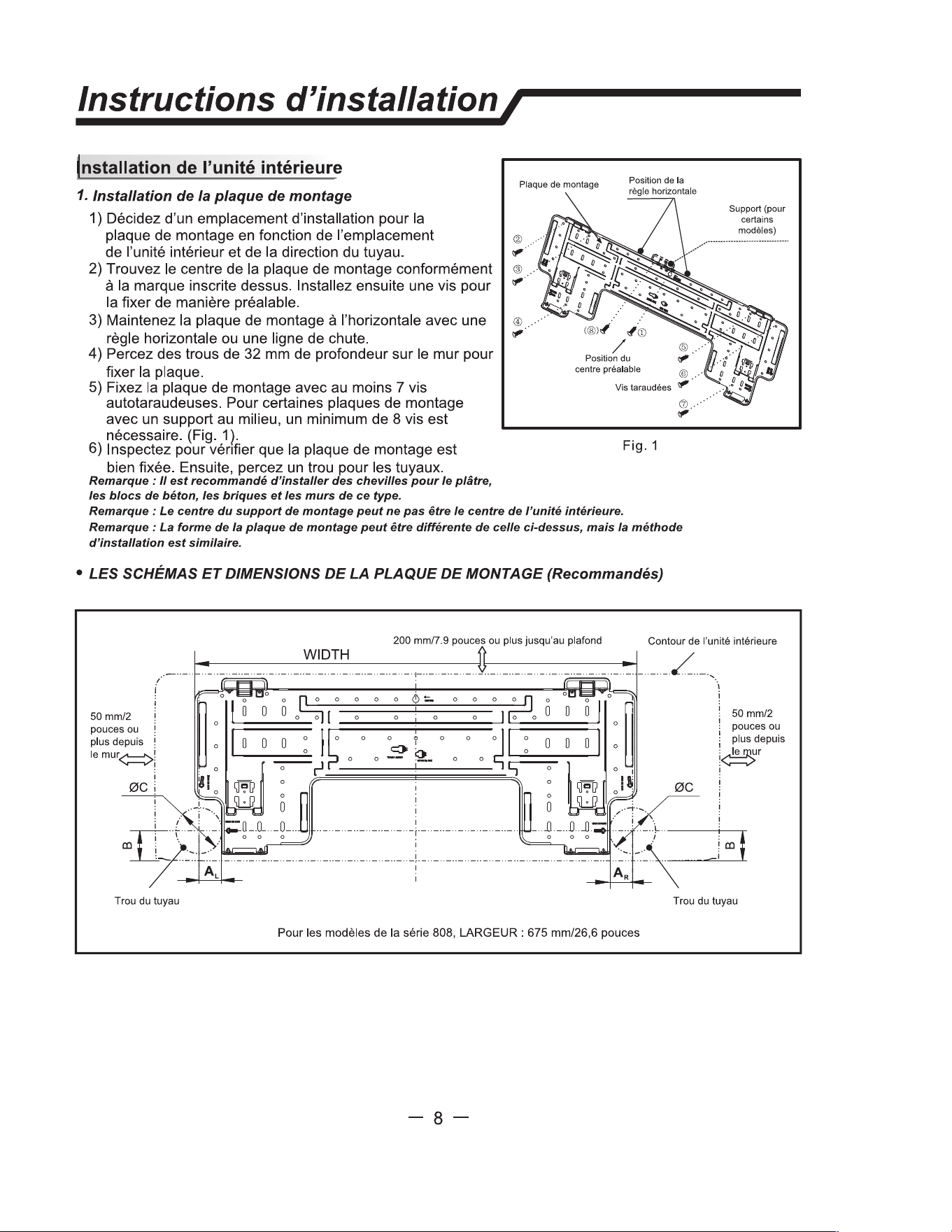
1. stalng the Mounting Plate
1) Decide an installing location for the mounting plate
2)
3)
4)
Mounting plate
Horizontal ruler
position
.... •·
·
·
·
_ �:
.
.
�
Q
O
•
•
•
•
•• .
.
.
.
0
(@), �
/
®
First fixed
Holder
(for some models)
5)
according to the indoor unit location and piping
direction.
Find the center of the mounting plate according to the
mark on it. Then Install a screw to fix it preliminary.
Keep the mounting plate horizontally with a horizontal
ruler or dropping line.
Drill holes of 1 1
/
4
"
in depth on the wall for fixing the
plate.
Fix the mounting plate with as least 7 self-tapping
screws. For some mounting plates with a holder in
the middle , at least 8 screws are re
q
uired. (Fig.
C
.4.1 ).
center position
@
.
6) Inspect if the mounting plate is well fixed. Then drill a
hole for piping.
Note: It recommended to insta screw anchors for sheet rock,
concte block, bck and such pe of wa.
Note: e center of the mounng bcket may be not the center of the indoor unit.
Tapping
screws
Fig.
C
.
4
.1
Note: e shape of your mounting plate may be erent m the one above, but insation method sa
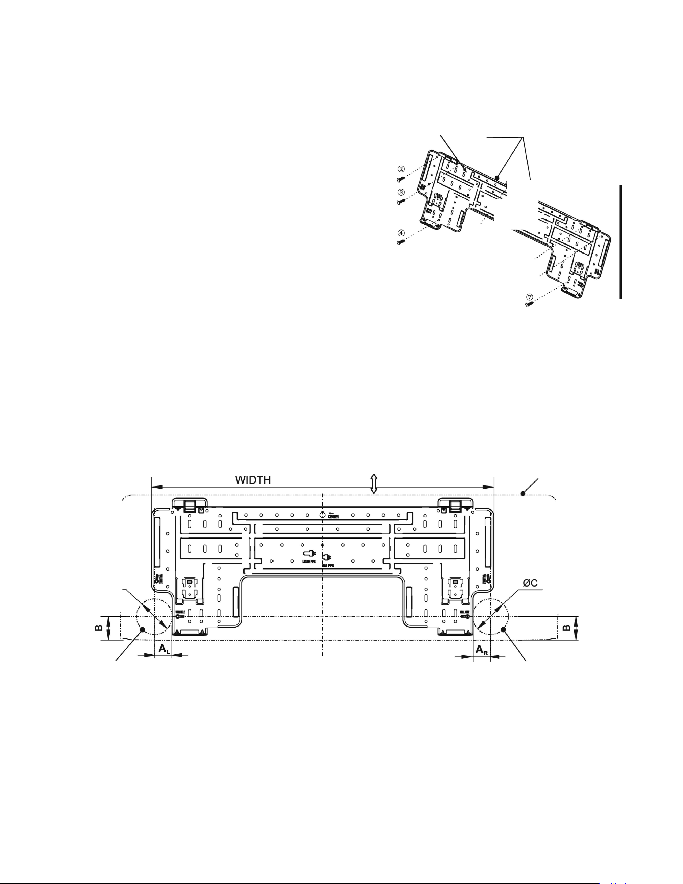
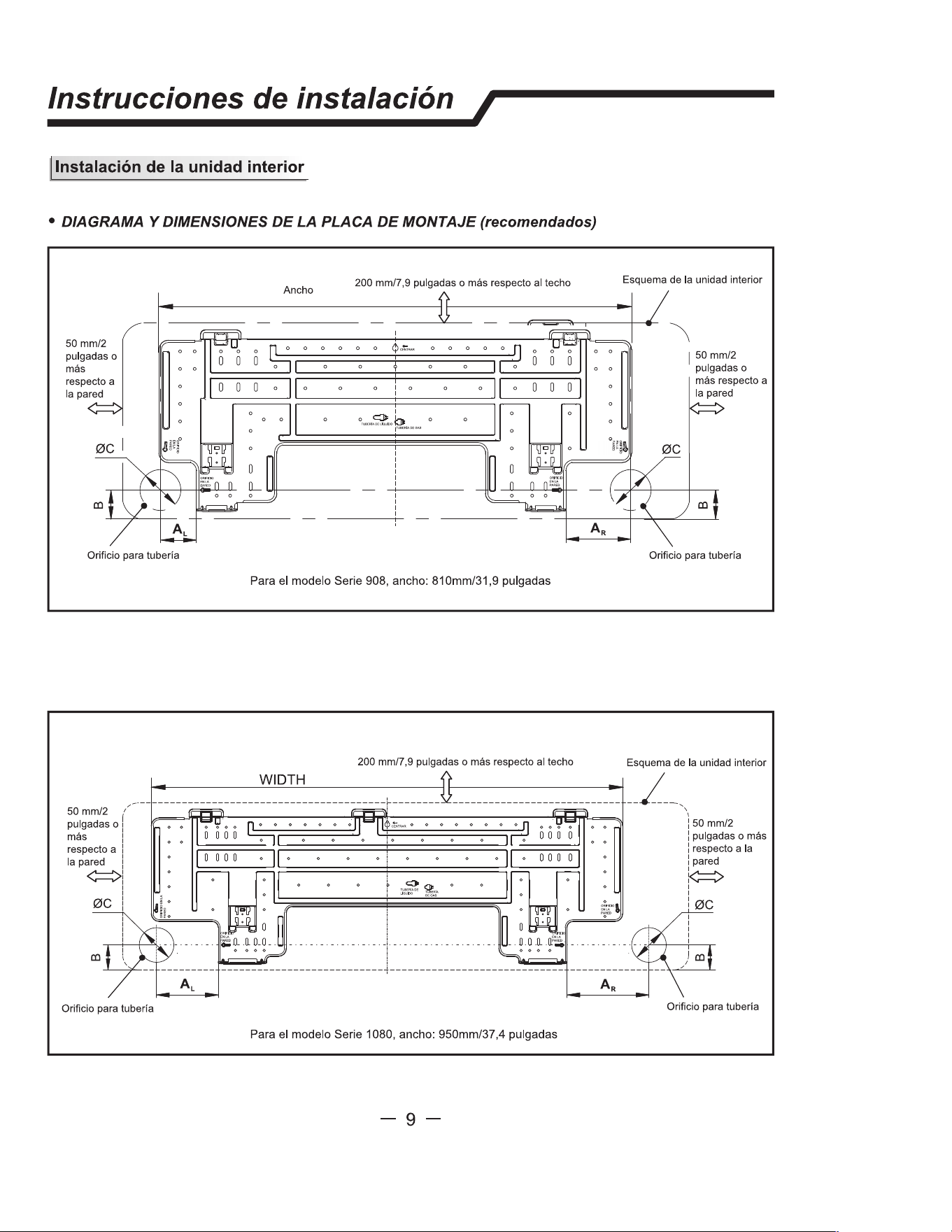
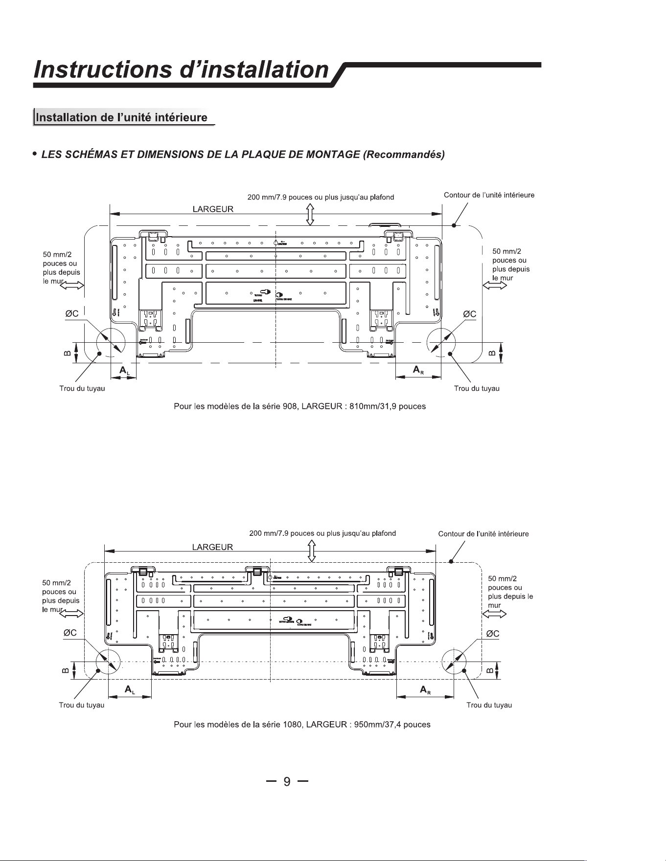
• E MOUNG PLATE DGRAMS AND DIMENSIONS (Recommende
!
!
2 in. or more!
to wall
�
i
i
0C
Pipe hole
8
in. or more to ceiling
For7K/9K/12KSeries Models, WIDTH: 26
5
/
8
in.
Indoor unit outline
2 in. or more
i towall
!
�
Pipe hole
C.4.2
C.4 Install Mounting Plate
9
C. INSTALLATION OF THE UNIT
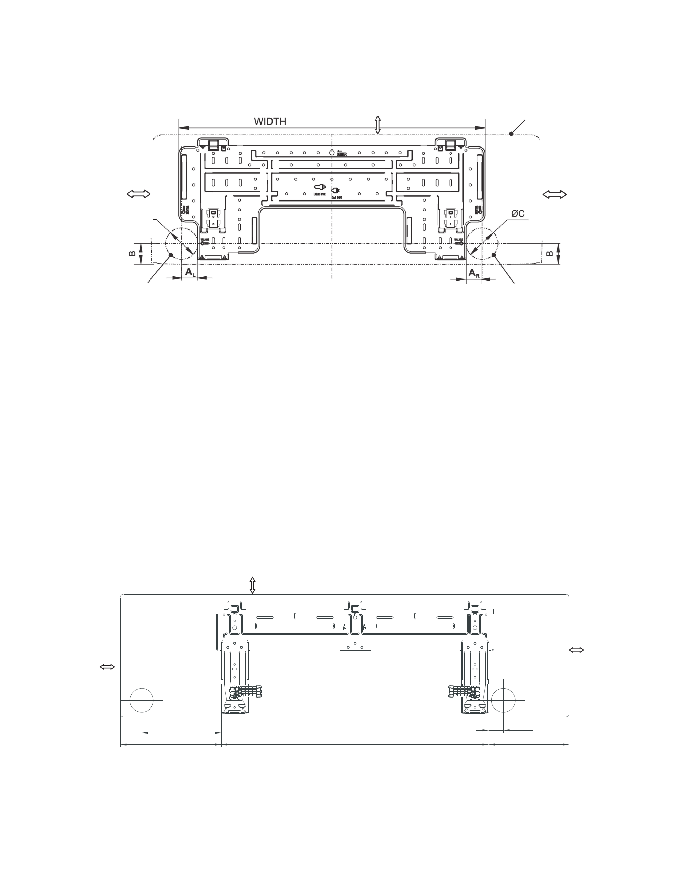
C.4 Install Mounting Plate
!
!
to wall
2 in. or more !
i
i
0C
Pipe hole
8
in. or more to ceiling
Indoor unit outline
For 18K/ 24K Series Models, WIDTH: 37
5
/
38
in.
2 in. or more
i towall
!
Pipe hole
C. 4.3
C.4.4
For 36K Series Model
50mm/2in
or more to wall
235.4mm/9.3in
298.9mm/11.8in
790.2mm/31.1in
43.2mm/1.7in
237.5mm/9.4in
50mm/2in
or more to wall
200mm/7.9in or more to ceiling
10
Installation insctions /
I
Table of Wa Hole Moung se per Unit Size
Size A
L
Size A
R
Unit Model
in
in
79K/12K Series
1 3/8 i
n
1 3/8 i
n
18K/24K Series
4 7/8 i
n
6
1/2
in
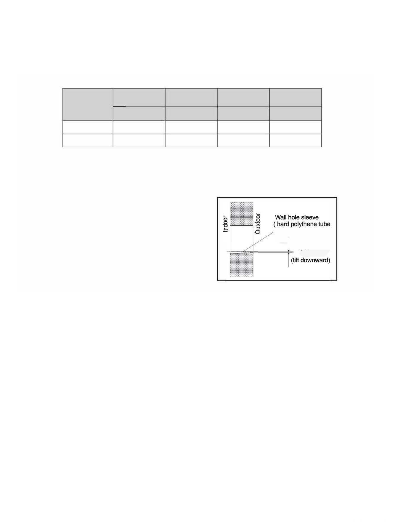
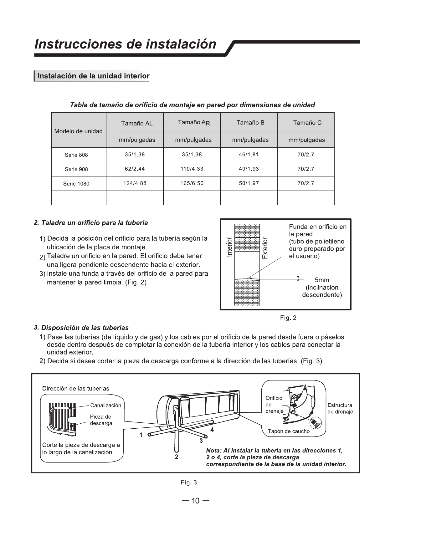
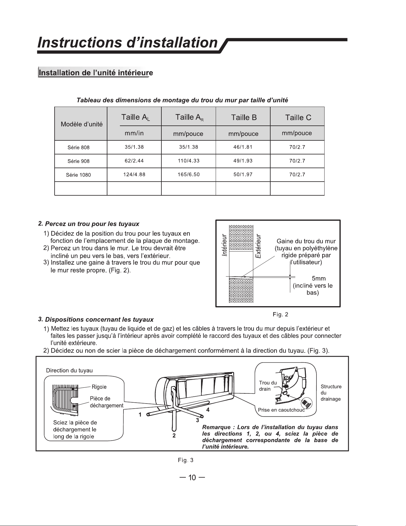
2. D a Hole for Piping
1) Decide the position of hole r piping according to the
location of mounting plate.
2) Drill a hole on the wall. The hole should tilt a little
downward toward outside.
3) Install a sleeve through the wall hole to keep the wall
tidy and clean. (Fig.
C
.
5
)
Size B
SizeC
in
in
1 3/4 i
n
2 3/4 i
n
2 i
n
2 3/4 i
n
prepared by user)
I
Fig.
C
.
5
3. Piping Pvision
1) Put the piping (liquid and gas pipe) and cables through the wall hole fm outside or put them through
fm inside after indoor piping and cables connection is complete to connect to the outdoor unit.
2) Decide whether to cut the knockout plate in accordance with the piping direction. (Fig.
C
.
6
.1)
Piping direion
Trough
K
nockout
plate
Saw the knockout plate
o along the trough
1
2
Fig.
C
.
6.1
�" � D;,
-
�
structure
Rubber plug �
Note: When instaing the pipe at the dicns
1,2 or 4, cut e cospong unloag piece
o e door unit base.
-9-
1/4 in
C.5 Drill Hole for Piping
C. INSTALLATION OF THE UNIT
11
stallation instrucns /
l Indoor unit installation
Note:
D
rain hose can be installed on either side of the unit. choosing bo sides drainage
connection, another pper din hose is needed as e is only
one in hose attached to the
unit. If choosing
one
side drainage connection, make su the din hole on the oer side is
plugged.
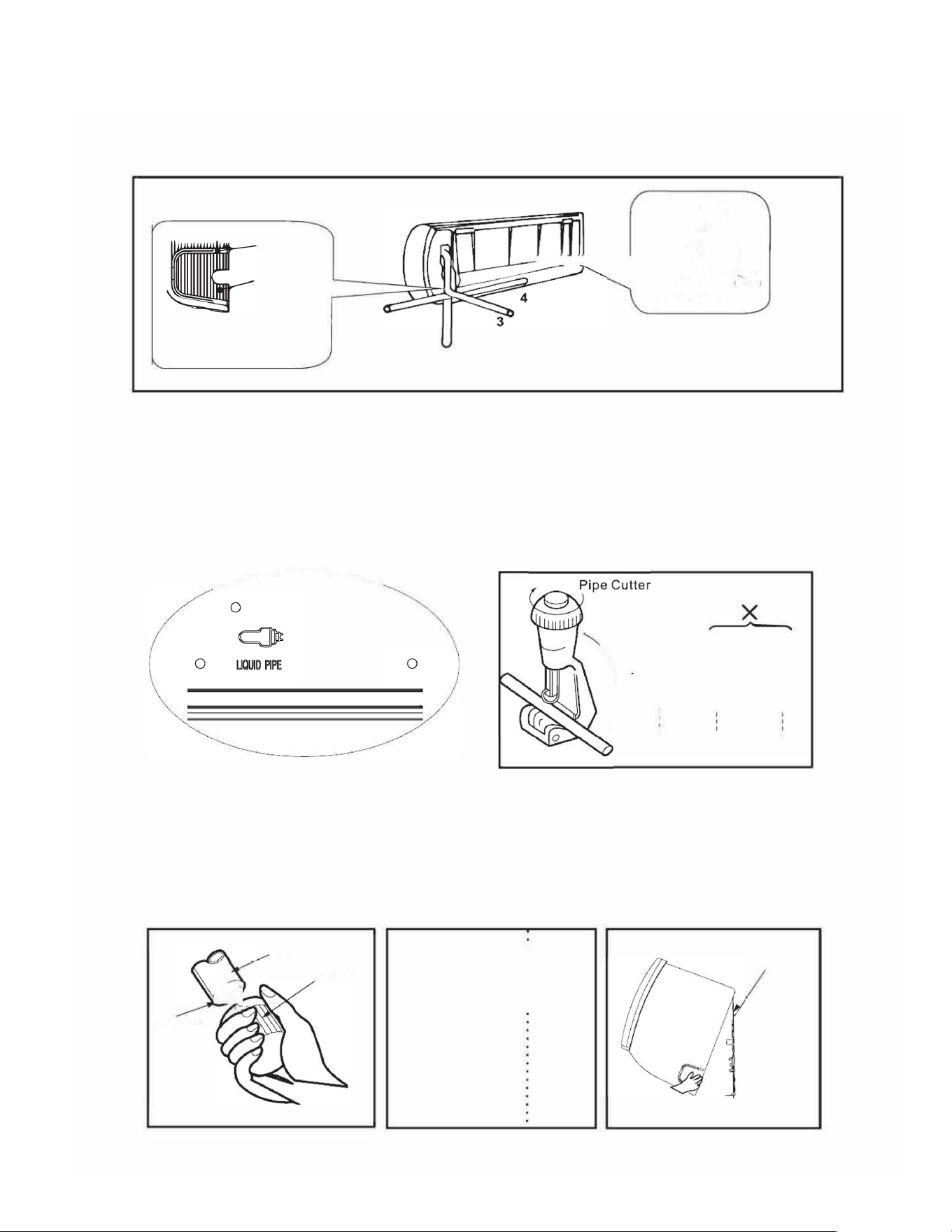
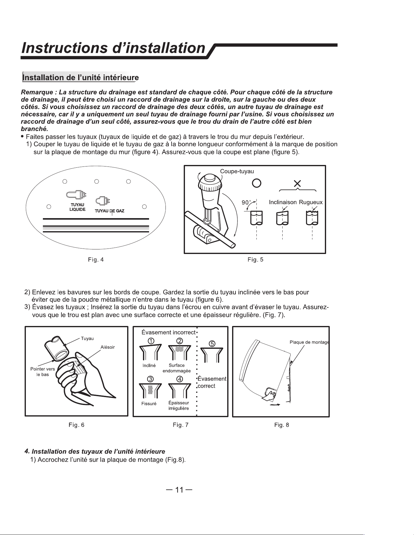
•Put the piping (liquid and gas pipe) and cables through the wall hole from outside.
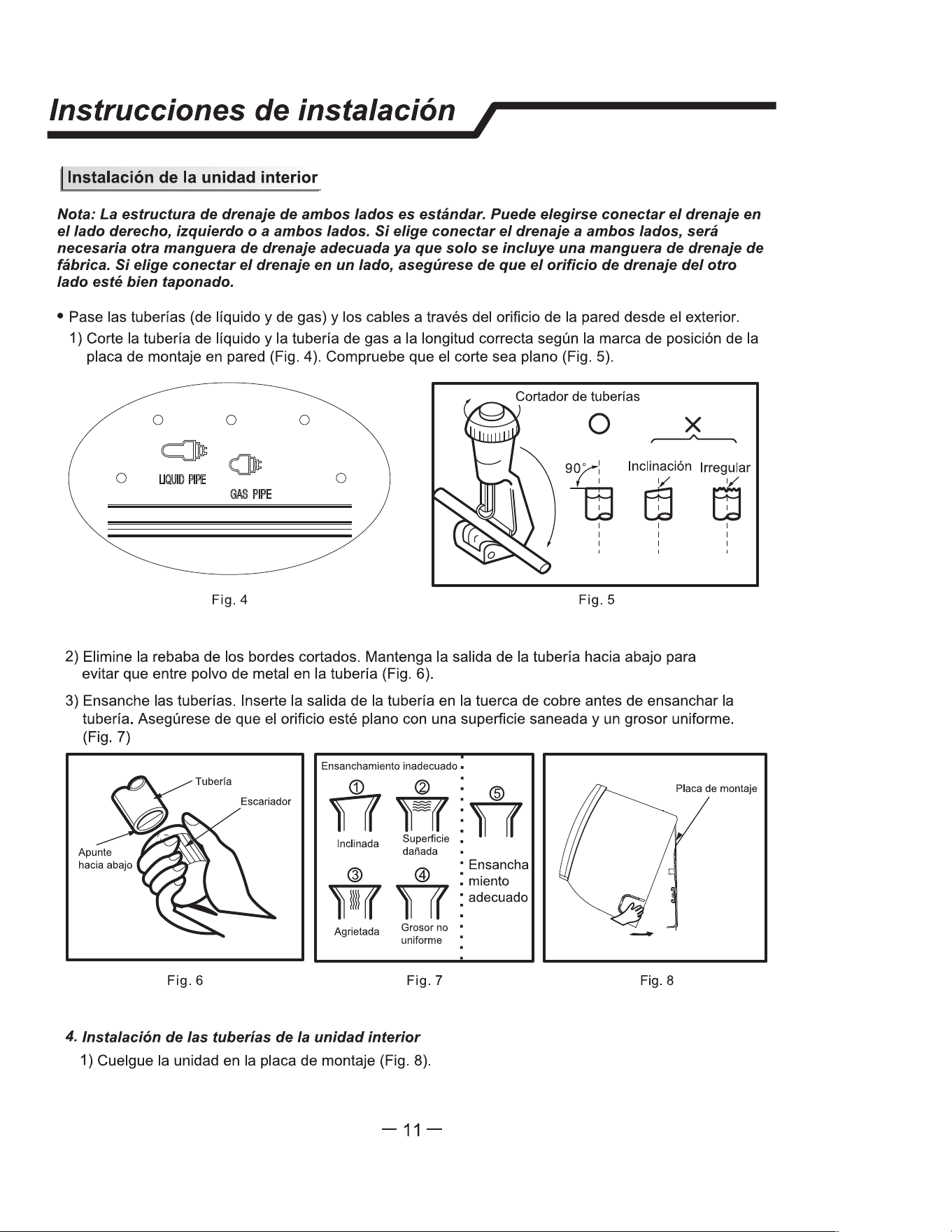
1)Cut the liquid pipe and gas pipe to the right length according to the position mark on the wall mounting
plate (Fig. C.6.2). Ensure that the cut is flat (Fig. C.6.3).
����
0 0
0
0
PI
Fig.C.6.2
)
9
�
S
�
d R
�
h
I
'
'
Fig.C.6.3
2)Remove burrs on the cutting edges. Keep the pipe outlet down to avoid getting the metal burrs into
the pipe(Fig. C.6.4).
3)Flare the pipes
.
Inse the pipe outlet into the copper nut bere flaring the pipe. Ensure that the hole
is flat with sound surface and even thickness. (Fig. C.6.5
)
0
Point Down
Pipe
Reamer
Improper Flaring
.
® : @
!
Inclined
Surface
Damaged
@ @
W
Cracked
Uneven
Thickness
proper
Flaring
Fig. C.6.4
Fig. C.6.5
4. Indoor Unit Piping Instaan
1)Hang the unit onto mounting plate
(Fig. C.7.1).
mounting plate
-
Fig. C.7.1
Installation insctions /
I
Table of Wa Hole Moung se per Unit Size
Size A
L
Size A
R
Unit Model
in
in
79K/12K Series
1 3/8 i
n
1 3/8 i
n
18K/24K Series
4 7/8 i
n
6
1/2
in
2. D a Hole for Piping
1) Decide the position of hole r piping according to the
location of mounting plate.
2) Drill a hole on the wall. The hole should tilt a little
downward toward outside.
3) Install a sleeve through the wall hole to keep the wall
tidy and clean. (Fig.
C
.
5
)
Size B
SizeC
in
in
1 3/4 i
n
2 3/4 i
n
2 i
n
2 3/4 i
n
prepared by user)
I
Fig.
C
.
5
3. Piping Pvision
1) Put the piping (liquid and gas pipe) and cables through the wall hole fm outside or put them through
fm inside after indoor piping and cables connection is complete to connect to the outdoor unit.
2) Decide whether to cut the knockout plate in accordance with the piping direction. (Fig.
C
.
6
.1)
Piping direion
Trough
K
nockout
plate
Saw the knockout plate
o along the trough
1
2
Fig.
C
.
6.1
�" � D;,
-
�
structure
Rubber plug �
Note: When instaing the pipe at the dicns
1,2 or 4, cut e cospong unloag piece
o e door unit base.
-9-
1/4 in
C.6 Piping Provisions
C. INSTALLATION OF THE UNIT
12
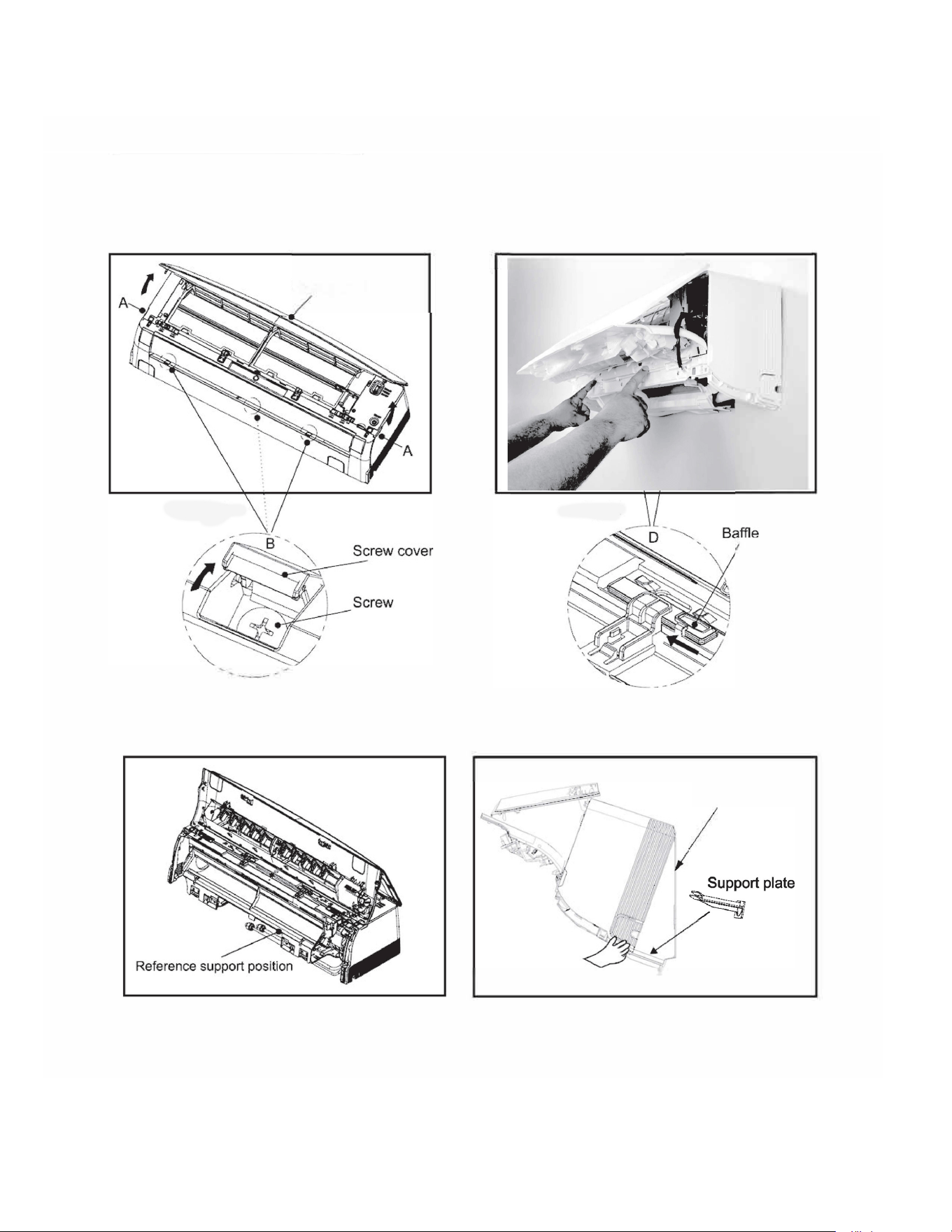
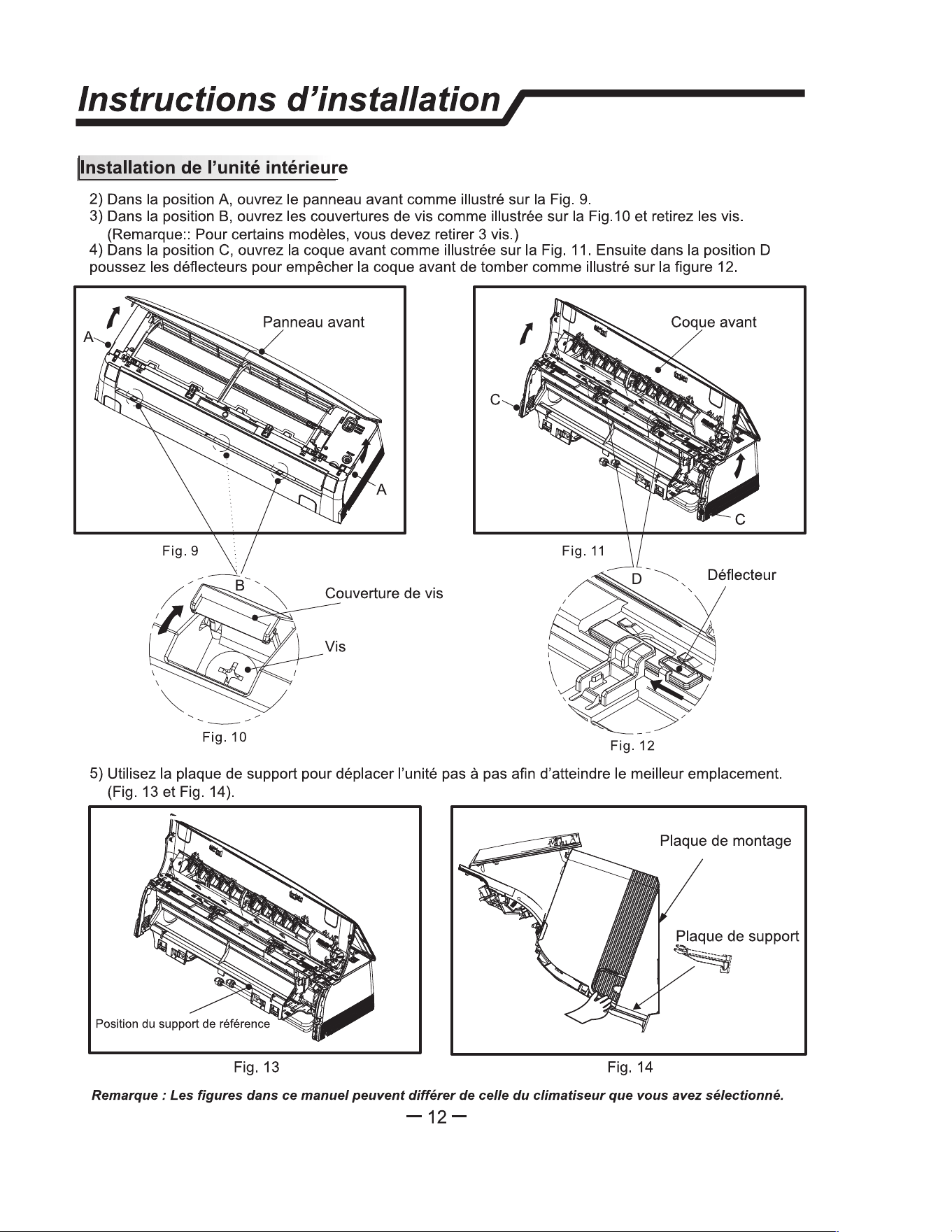
Indoor unit installation
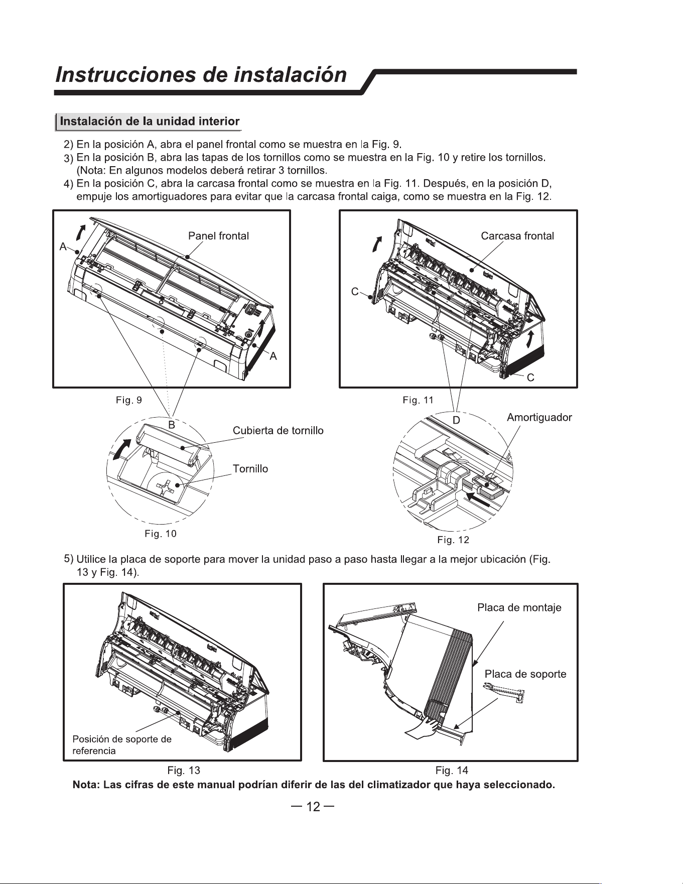
2) In the A position, open the front panel as shown in Fig. C.
7
.2.
3) In the B position, open the screw covers as shown in Fig. C
.7.3
and remove the screws. (Note: For
some models, you need to remove 3 screws.)
4) In the C position, open the front shell as shown in Fig. C.
7.4
. Then in the D position, push the baffles
to prevent the front shell from falling as shown in Fig. C.
7
.5.
Front panel
Fig.
C
.
7.3
Fig.
C
.
7.5
5) Use the support plate to move the unit step by step to reach the best location. (Fig. C.
7
.
6
and Fig. C.
7
.
7
).
mounting plate
Fig. C.
7
.
6
Fig.C.
7
.
7
Note: The a
pp
earance of the model in this manual may dir m that of e air conditioner
you have selecd.
C.7.2
C.7.4
stallation instrucns /
l Indoor unit installation
Note:
D
rain hose can be installed on either side of the unit. choosing bo sides drainage
connection, another pper din hose is needed as e is only
one in hose attached to the
unit. If choosing
one
side drainage connection, make su the din hole on the oer side is
plugged.
•Put the piping (liquid and gas pipe) and cables through the wall hole from outside.
1)Cut the liquid pipe and gas pipe to the right length according to the position mark on the wall mounting
plate (Fig. C.6.2). Ensure that the cut is flat (Fig. C.6.3).
����
0 0
0
0
PI
Fig.C.6.2
)
9
�
S
�
d R
�
h
I
'
'
Fig.C.6.3
2)Remove burrs on the cutting edges. Keep the pipe outlet down to avoid getting the metal burrs into
the pipe(Fig. C.6.4).
3)Flare the pipes
.
Inse the pipe outlet into the copper nut bere flaring the pipe. Ensure that the hole
is flat with sound surface and even thickness. (Fig. C.6.5
)
0
Point Down
Pipe
Reamer
Improper Flaring
.
® : @
!
Inclined
Surface
Damaged
@ @
W
Cracked
Uneven
Thickness
proper
Flaring
Fig. C.6.4
Fig. C.6.5
4. Indoor Unit Piping Instaan
1)Hang the unit onto mounting plate
(Fig. C.7.1).
mounting plate
-
Fig. C.7.1
C. INSTALLATION OF THE UNIT
C.7 Indoor Unit Installation
13
Installation insctions /
I
Indoor unit installation
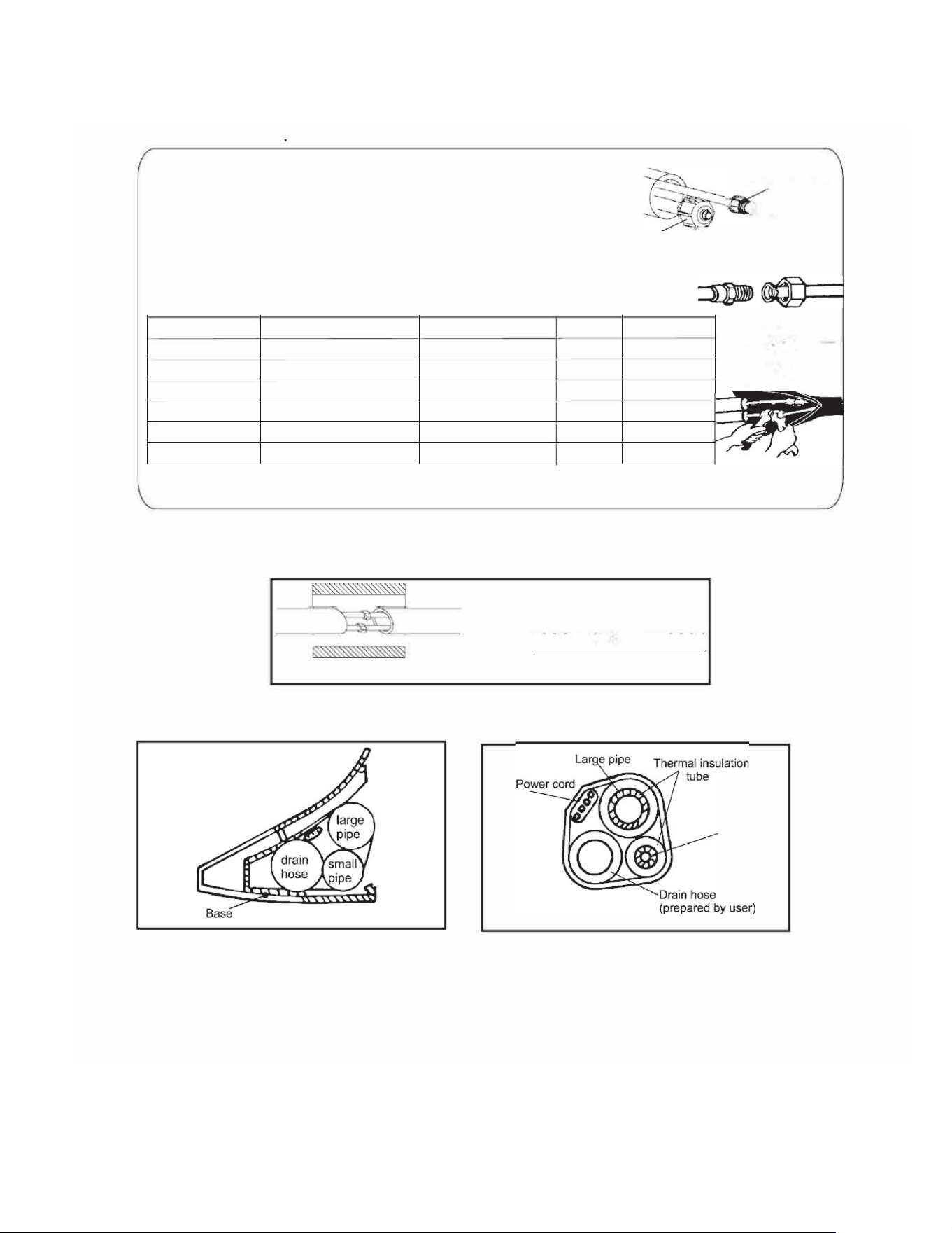
6) Connect the piping
Piping Connection:
Small sealing cap
'
a.
b.
Before unscrewing the big and the small sealing caps, press the small
sealing cap with the finger until the exhaust noise stops, and then loosen
the finger.
Connect indoor unit pipes with two wnches. Pay special attention
to the allowed toue as shown below to prevent the pipes, connectors
and flare nuts from being deformed and damaged.
Press here
Big sealing cap
c. Pre-tighten them with fingers at first, then use the wrenches.
If you don't hear the exhaust noise, please contact customer service.
24K-36K
Torque (ft lbs
Nut width Min.thickness
�
7K-18K
Pipe size (inches)
LiquidSide (1/4)
11-15ft-lbs
0.02 "
7K-12K
Gas Side ( cl> 9.53 or 3/8 )
22-26ft-lbs
18K
24K-36K
36K
Gas Side ( cl> 12 or 1/2)
37-41ft-lbs
Gas Side ( cl> 16 or 5/8)
Gas Side ( 19 or 3/4)
44-48ft-lbs
52-55ft-lbs
I I
�
Thermal insulation
wrapped with vinyl type
Fig. C.5.9
No: Wp e pipg join eal insulation matea and en wp th a vin tape.
Fig. C.5.10
Fig. C.5.11
Small
pipe
Note: Place the drain hose under the pipes.
Note: Insulation material uses polythene foam over
1/4"
(
6
)
mm
in thickness.
Note: Drain hose Is prepared by user.
Note: Note: The appearance of the model in this manual may differ from that of the air
conditioner you have selected.
Table C.7.8
7) After connecting piping as required, install the drain hose. Then connect the power cords. After connecting, wrap the piping,
cords and drain hose together with thermal insulation materials(
Fig. C.7.9-C.7.11).
Model
Liquid Side ( 3/8)
22-26ft-lbs
5
5
/
/
8
8
"
"
7/8"
0.024"
7
7
/
/
8
8
"
"
15/16"
1 1/8"
1 1/4"
0.024"
0.024"
0.024"
0.039"
C. INSTALLATION OF THE UNIT
C.7 Indoor Unit Installation
14
_ Gas valve
(
Indoor unit installation
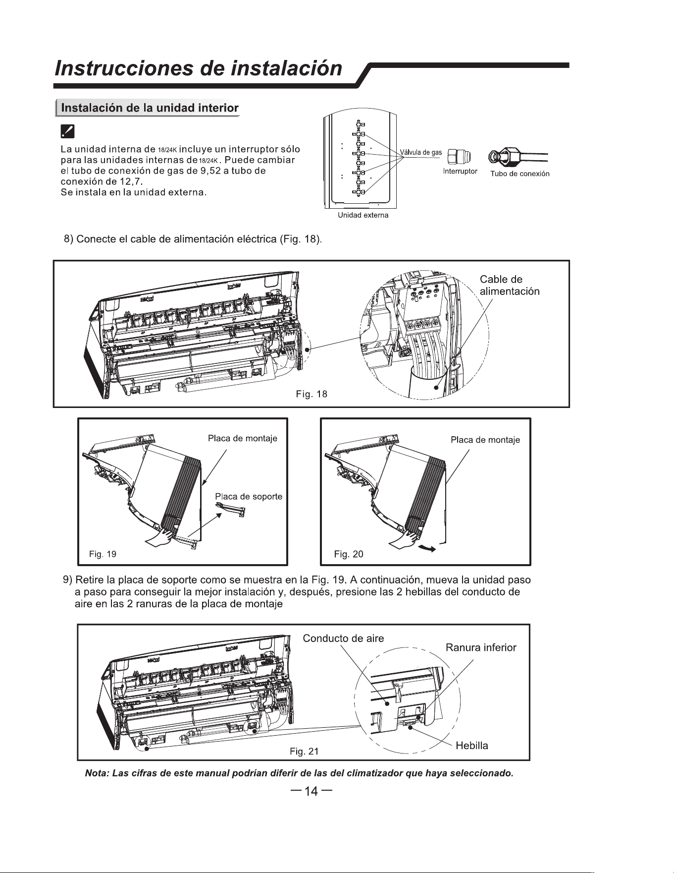
The 18K/24K indoor unit include the switch tie-in accesso
only r 18K/24K indoor i
f
re
q
uired. It may switch
3
/8
"
gas
connection tube into 1/2
"
or 5/8
"
connection tube.
It is installed outdoor unit.
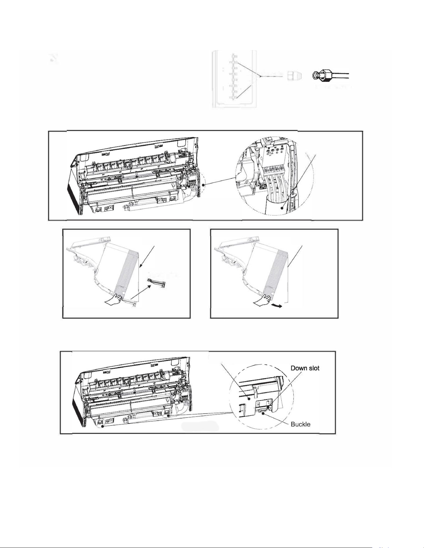
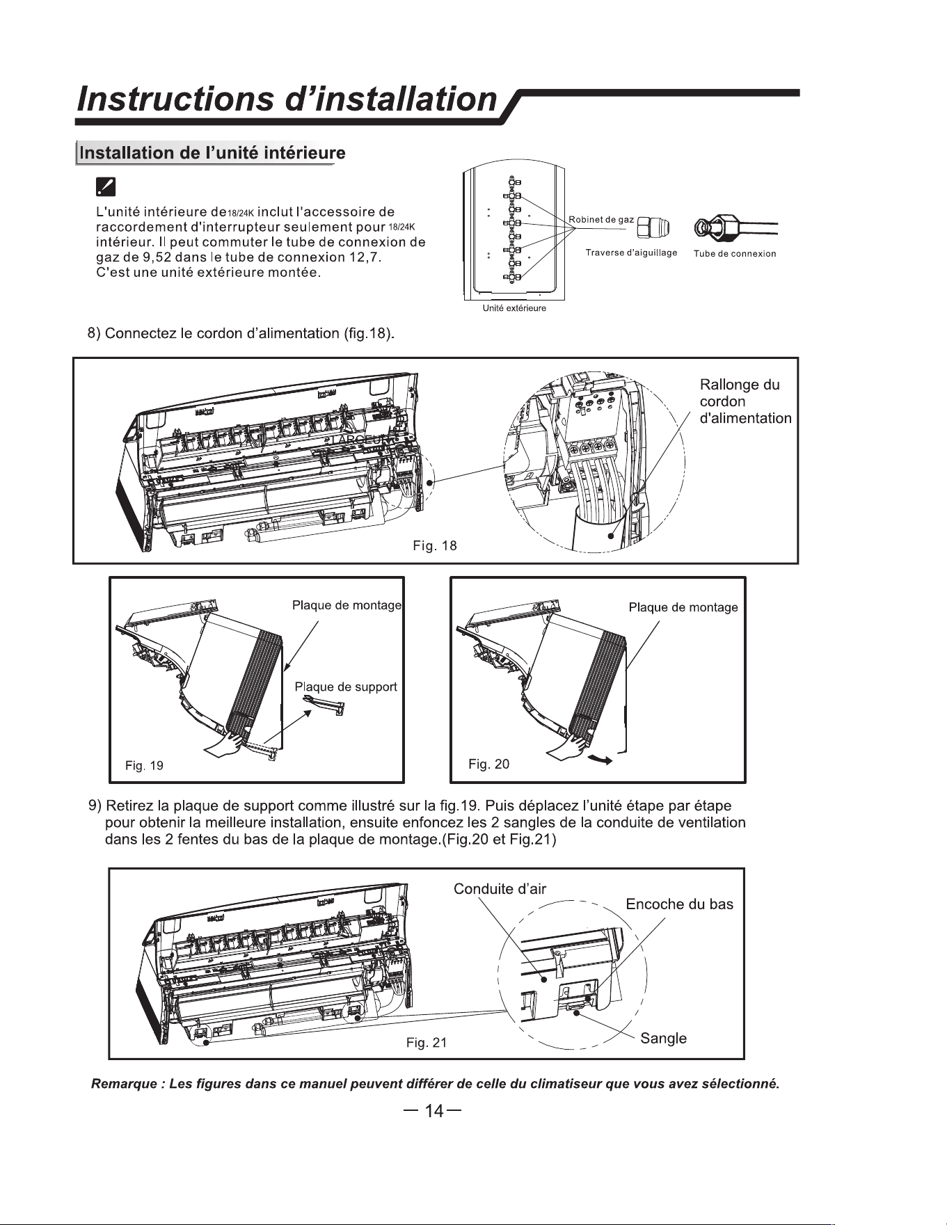
8) Connect the power connecting cord (Fig. C.
5
.1
2
).
Fig.
C
.5.12
mounting plate
Suppo plate
Fig.
C
.5.1
3
·.�
Outdoor unit
Fig.
C
.5.14
Flare
adapte
r
Connection tube
. Power connecting
. cord
mounting plate
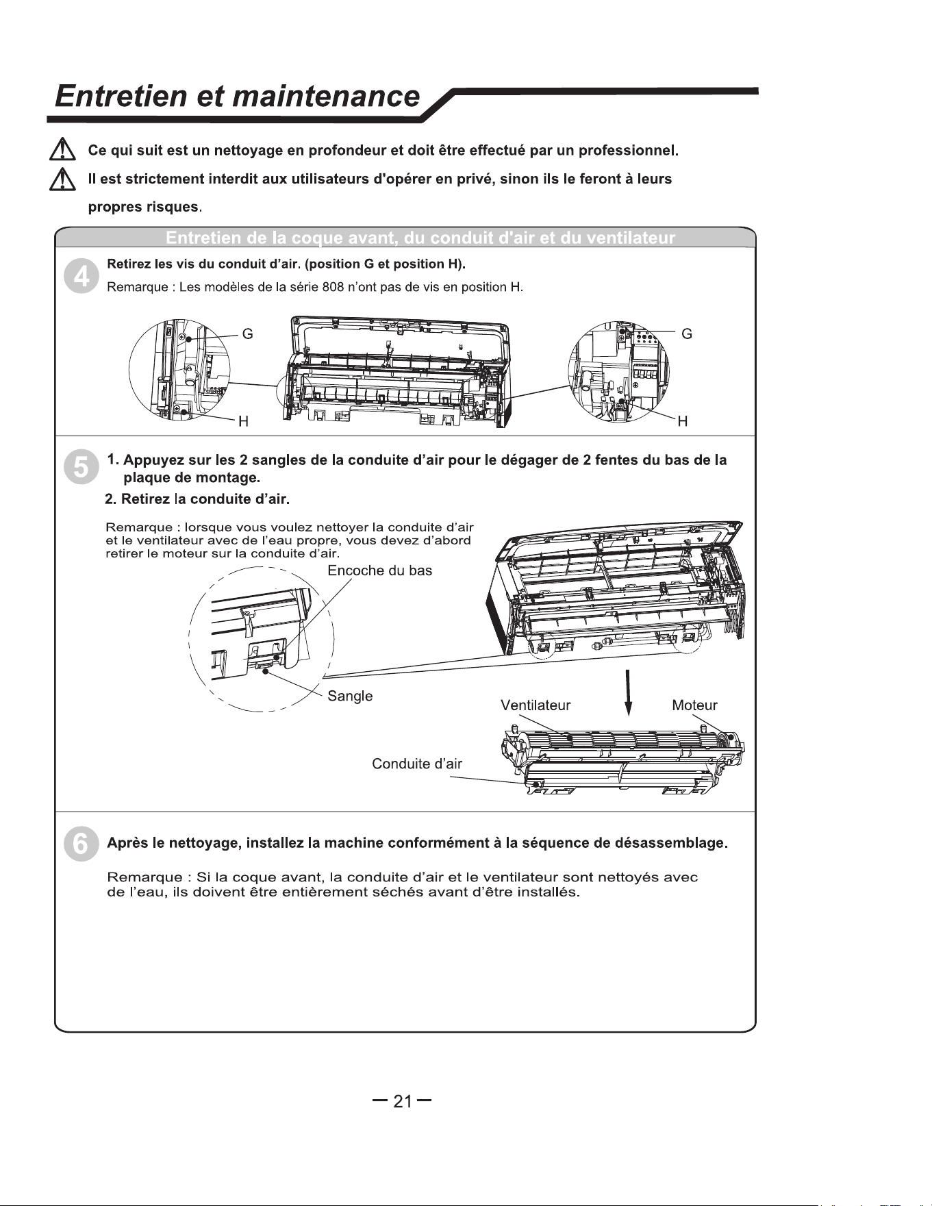
9) Remove the support plate as shown in Fig. C.
5
.1
3
Then move the unit step by step to reach the best
installation, then press the 2 buckles of the air duct into 2 down slots of the mounting
plate.(Fig. C.
5
.1
4
and Fig.C.
5
.1
5
)
Air duct
C.5.15
C. INSTALLATION OF THE UNIT
C.7 Indoor Unit Installation
15
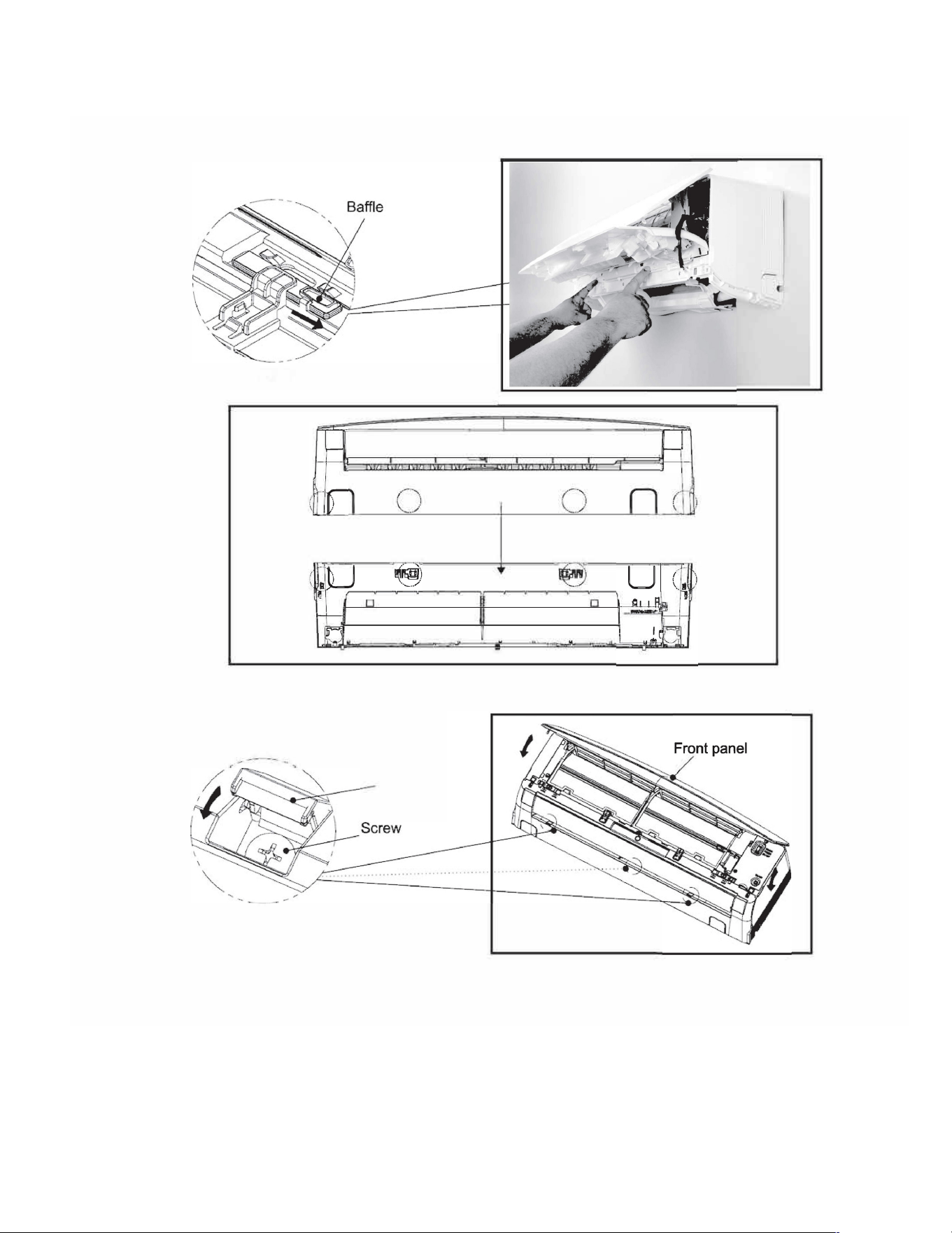
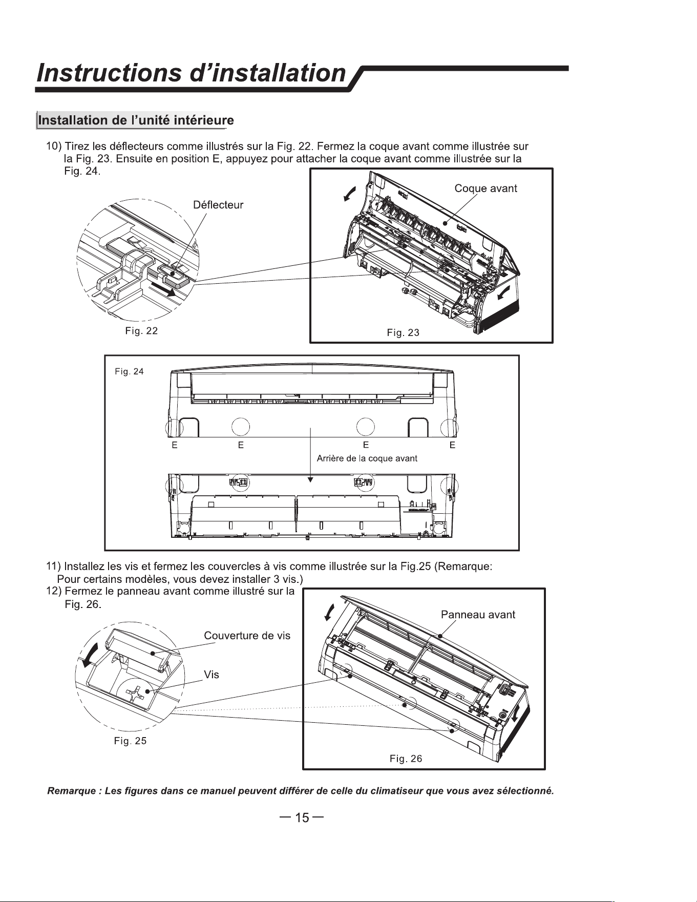
Insllation instructions /
Indoor unit installation
10) Pull the baffles as shown in Fig. C.5.20 Close the front shell as shown in Fig. C.5.21 . Then press the E
position to fasten the front shell as shown in Fig. C.5.22
Fig.
C
.
5
.2
0
Fig.C.5.21
Fig.
C
.
5
.22
E E
E E
Back of the fnt shell
□ □ □ □
11) Install the screws and close the screw covers as shown in Fig. C.5.23 (Note: For
some models, you need to install 3 screws.)
12) Close the front panel as shown in Fig. C.5.24
Screw cover
Fig.
C
.5.2
3
Fig.
C
.5.2
4
Note: e a
pp
earance of the model in th manual may dr m at of e a condioner you have selected.
-14-
C. INSTALLATION OF THE UNIT
C.7 Indoor Unit Installation
16
Insllation Insctions,
l Pr and ng
nnng of e Ca
• Indoor Unit
Ft n
inal
(Inse)
nne the er to e indr unit nnng
the wis the inals on the ntrol indidually
in aan with e outdr unit nn.
N: For mels, it sa m the in
nn the indr unit inal.
�����
�
��
bl
• Ouoor Unit
1) move the ble m e un by loosenlng
the s. Conne the wi e telnals on the ntl
indidually per circuit diagram posted on inside of
access door.
2) S e r on e ntl
with ble clamp.
3) Reinll e ble s boa the original ion
th e sc.
4) U a gnized uit bker n e er
u and e unit. A dlsn de to adua
dinn all supply lin must d.
uon:
Indr unit
Chis
Our unit
1. Never il have an individual pr ciit slly r e air nditioner.
2. Always r to the rcuit diagm d on a inside e a dr for wiring.
3. Con that e ble this is as sied in the er u specition.
4. Chk e s and make su at they a all gh sned ar ble nneon.
5.
su insll an leakage ci bker in t or ist aas.
S
E. ELECTRICAL
WARNING
Electrical Shock Hazard
Always ensure power is
disconnected before attempting
to connect wires.
GROUNDING
Unit MUST be grounded from branch
circuit to unit, or through separate
ground wire. Be sure that branch circuit
or general purpose outlet is grounded.
Do NOT use an extension cord.
ELECTRICAL
DISCONNECT
If national or local electrical codes require
an electrical disconnect for the indoor
unit, use a 3 pole disconnect.
Model Wire Diameter(AWG)
Interconnecting Wire
7-9k 14-4 AWG 600V THHN
12k 14-4 AWG 600V THHN
18k 14-4 AWG 600V THHN
24-36K 14-4 AWG 600V THHN
Table E.1
Indoor Unit
Connect the power cord to the indoor unit by connecting the wires to the
terminals on the control board individually in accordance with the outdoor unit
connection.
Note: For some models, it is necessary to remove the cabinet to connect to the
indoor unit terminal.
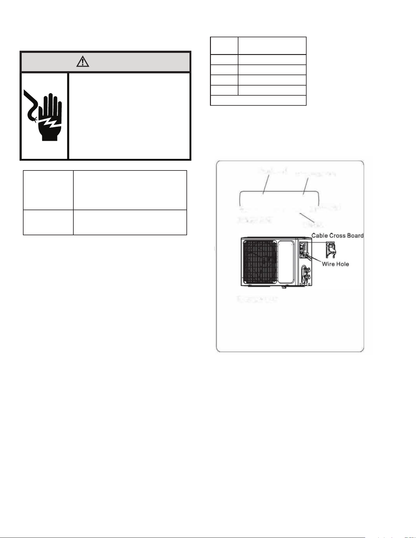
•Outdoor Unit
1. Remove the cable cross board from the unit by loosening the screw. Connect
the wires to the terminals on the control board individually per circuit diagram
posted on inside of access door. Refer to Figure E.2.
2. Secure the power cord onto the control board with cable clamp.
3. Reinstall the cable cross board to the original position with the screw.
Figure E.2
17
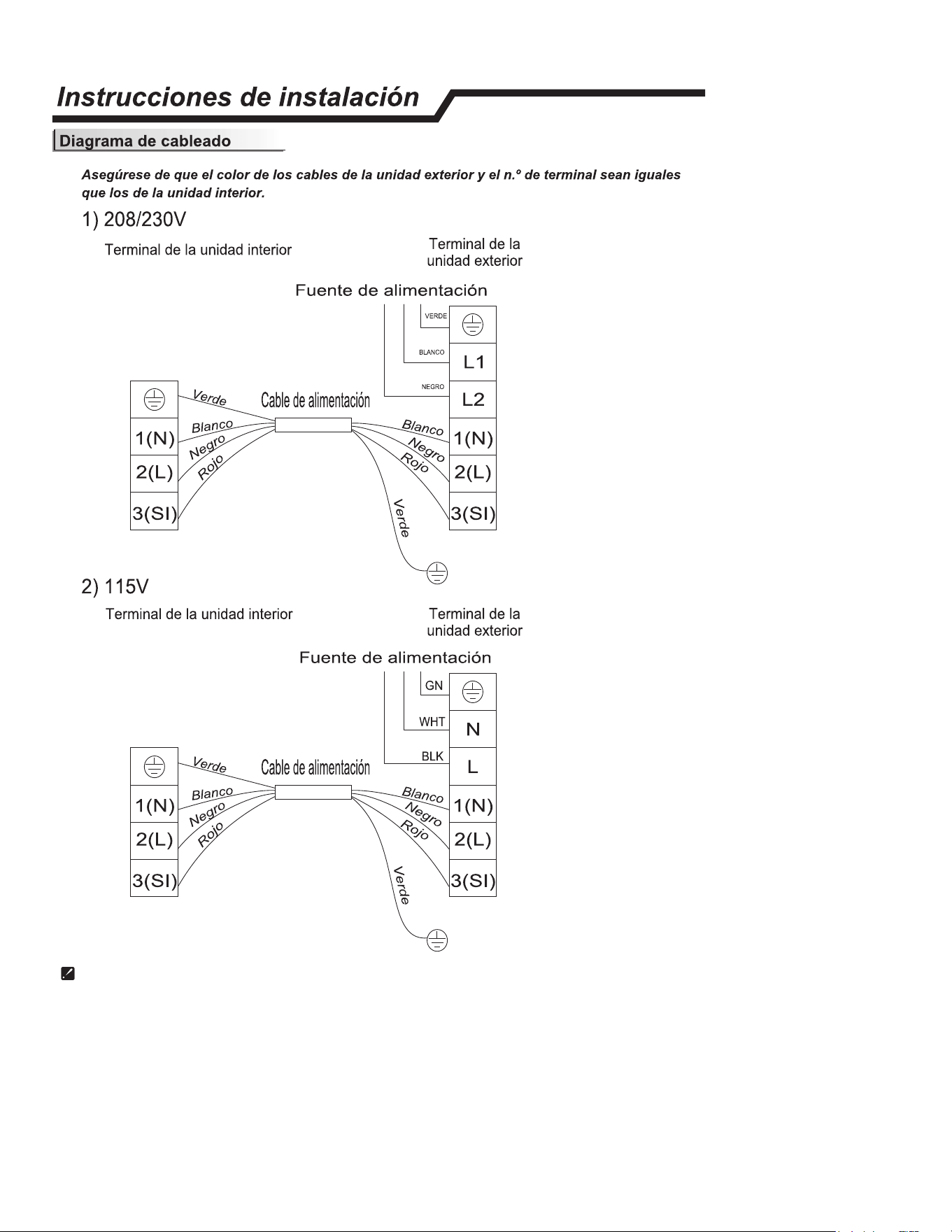
E. ELECTRICAL
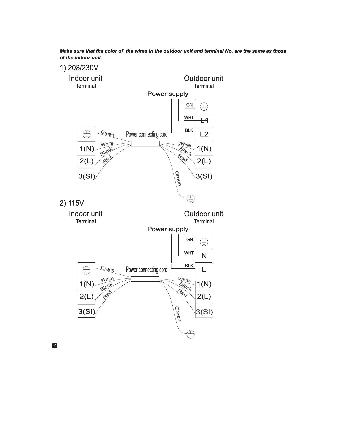
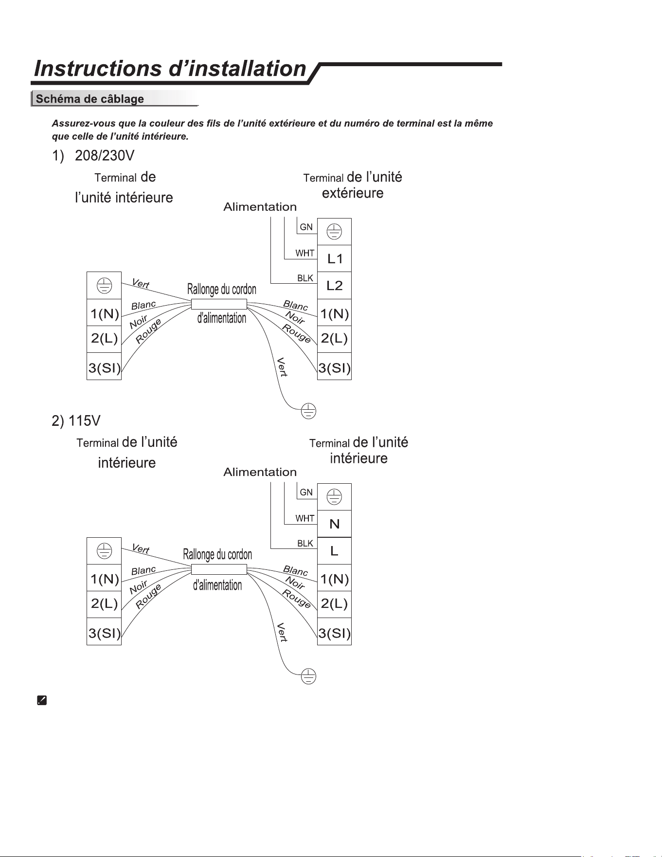
E.1 Indoor Unit Wiring Connection Diagram
Diagram is reference only, actual product terminals should be followed.

18
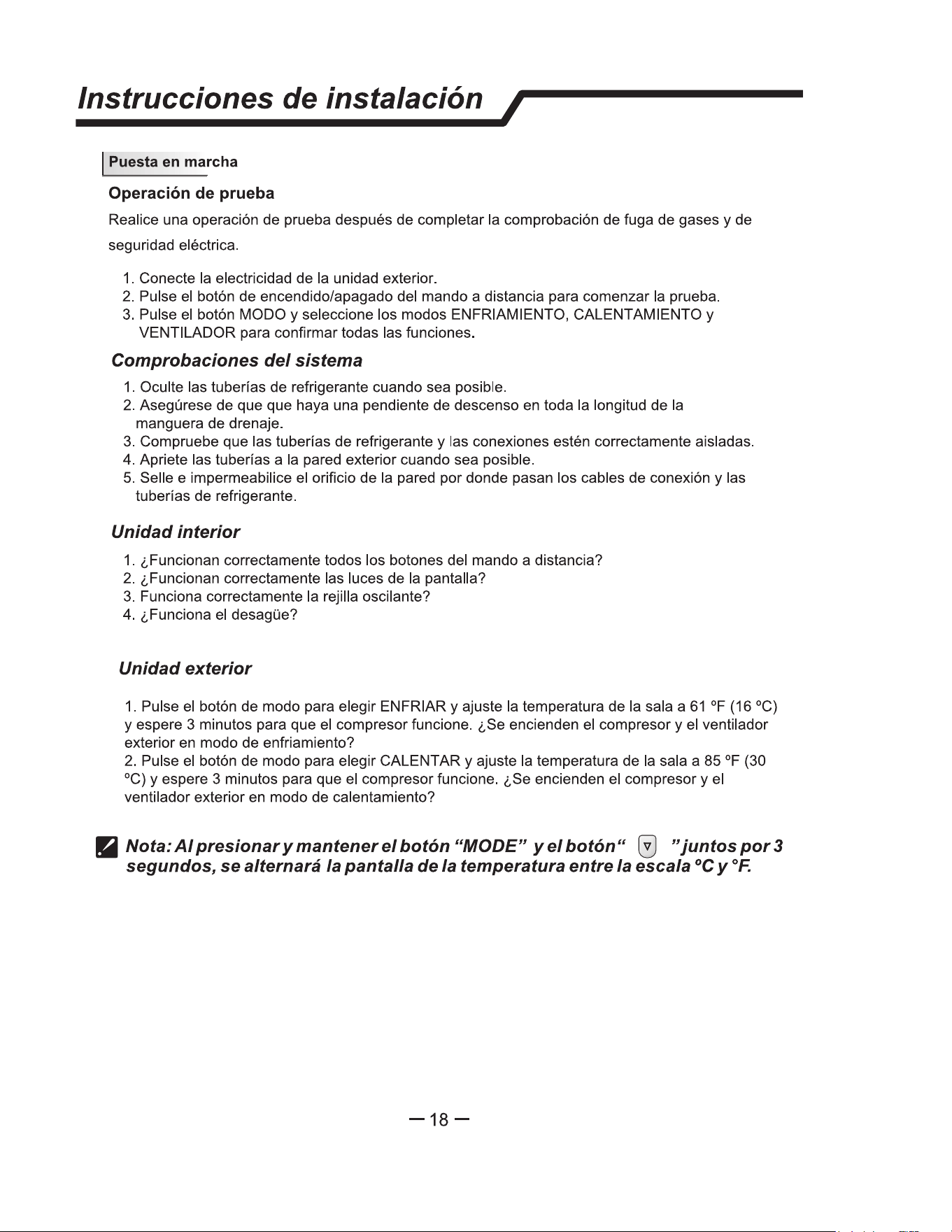
J. STARTUP AND OPERATION
J.1 Checklist and Operation Test
Present the owner or operator of the equipment with the Installation &
Operation Manual, all accessory installation instructions, and the name,
address, and telephone number of the Authorized Friedrich Warranty
Service Company in the area for future reference if necessary. Inspect
the unit for any damage to the coils and tubing that could cause a leak.
Test Operation
System Checks
Perform test operation after completing gas leak and electrical
safety check.
1. Conceal refrigerant pipes where possible.
2. Make sure drain hose slopes downward along entire length at a
slope of 1/4”(inch) per ‘(foot).
3. Ensure all refrigerant pipes and connections are properly
insulated.
4. Fasten pipes to outside wall, when possible.
5. Seal and weatherproof wall hole which the interconnecting wires
and refrigerant pipes pass through.
Perform test operation after completing gas leak and electrical
safety check.
1. Turn on electrical disconnect to outdoor unit.
2. Push the “ON/OFF” button on Remote Controller to begin testing
or press and hold Emergency ON/OFF button for 5 seconds to force
test mode.
3. Push MODE button, select COOLING, HEATING, FAN mode to
confirm all functions.
Indoor Unit
1. Do all Remote controller’s buttons function properly?
2. Do the display panel lights work properly?
3. Does the swing louver function properly?
4. Does the drain work?
Outdoor Unit
1. Push the mode button to COOL and adjust the
room setting to 61 °F(16°C) deg. Wait up to 3 minutes from
compressor time guard. Does compressor and outdoor fan turn on
in cooling mode?
2. Push the mode button to HEAT and adjust
the room setting to 85 °F(30°C) deg. Wait up to 3 minutes for
compressor time guard. Does compressor and outdoor fan turn on
in heat mode?
Unit protection will prevent the unit from restarting for 3 minutes if
operations stops, or modes are changed.
Preheat
At the beginning of the HEATING operation, the airflow from the
indoor unit is discharged 2-5 minutes later.
Defrost
In HEATING operation the appliance will defrost (de-ice)
automatically to raise efficiency. This procedure usually
lasts 2-10 minutes. During defrosting, fans stop operation.
After defrosting completes, it returns to HEATING mode automatically.
19
Installation Manual
-
�
m
�
z,
0
r
ESPANOL
20
ESPAÑOL
El tamaño mínimo de la habitación (refrigerante R-32 o R-454B) está determinado por la carga total de refrigerante en el sistema. Utilice esta tabla para determinar
el tamaño mínimo de la habitación en la que se puede instalar el cabezal interior.
Un minuto (pies
cuadrados)
Altura de instalación (pies y pulgadas)
Mc(oz) 6 6' 6" 7' 2" 7' 10" 8' 2"
64 71 64 58 53 51
65-71 78 71 64 59 57
72-77 86 78 71 65 62
78-85 94 85 77 71 68
86-92 102 92 83 77 74
93-99 110 99 90 82 79
100-106 117 105 96 88 85
Antes de instalar la unidad, utilice la siguiente tabla para determinar la carga total de refrigerante de la unidad. Si la carga total es inferior a 64 oz. No hay restric-
ciones en el tamaño de las habitaciones. Si la carga total es superior a 64 oz. consulte el cuadro anterior. Utilice la carga total, la altura de la parte inferior de la uni-
dad y la tabla anterior para determinar los pies cuadrados mínimos de la habitación en la que se puede instalar la unidad interior. Si las habitaciones están conectadas
mediante una abertura por la que las personas puedan caminar pero sin puerta instaladas, esas áreas pueden considerarse un solo espacio.•
Mc(oz) Tipo de refrigerante Precarga con 25 pies
de juego de líneas
25-50 ft 50-75 ft add 75-100 ft
Indoor Unit Model Outdoor Unit Model
FAHSW09A1C FSHSR09B1C
R-32
21.2 27.7 33.2 N/A
FAHSW12A1C FSHSR12B1C 21.9 27.4 32.9 N/A
FAHFW18A3D FSHSR18B3D 45.9 51.4 56.9 62.4
FAHFW24A3D FSHSR24B3D 47.7 55.7 63.7 71.7
FAHSW36A3D FSHSR36B3D 72.4 83.2 93.9 104.7
FAHM07A3D Multizona
R-454B
Consulte el IOM del condensador exterior multizona para obtener más información sobre la
restricción del tamaño de la habitación y la aplicación del sensor A2L
FAHSW09A1AC FPHSR09A1C 33.5 39 44.5 N/A
FAHFW09A3D FPHSR09A3D 35.3 40.8 46.3 N/A
FAHSW12A1C FPHSR12A1C 35.3 40.8 46.3 N/A
FAHFW12A3D FPHSR12A3D 38.1 43.6 49.1 N/A
FAHFW18A3D FPHSR18A3D 52.9 58.4 63.9 69.4
FAHFW24A3D FPHSR24A3D 70.6 78.6 86.6 94.6
Al agregar refrigerante al sistema para un juego de líneas adicional, consulte la placa de identificación del modelo y las instrucciones de instalación de la unidad
exterior para conocer la cantidad de carga adecuada.
21
ESPAÑOL
22
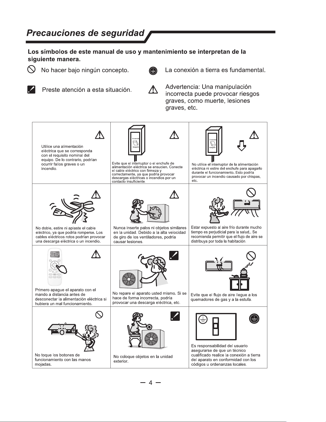
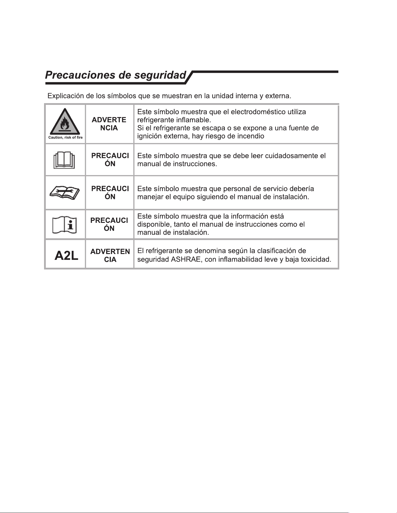
lnstrucciones de seguridad
1
• 1. Para garantizar que la unidad funcione con normalidad, lea atentamente el manual antes de
realizar la instalacion y realicela en estricta conformidad con este manual.
•
2. No deje que entre aire en el sistema de refrigeracion o descargue el refrigerante cuando traslade
el climatizador.
• 3. Conecte adecuadamente el climatizador a tierra.
• 4. Compruebe detenidamente las cables de conexion y las tuberfas, y asegurese de que las
conexiones sean correctas y firmes antes de conectar la alimentacion del climatizador.
•
5. Debe disponer de un interrupter neumatico.
• 6. Despues de la instalacion, el consumidor debe operar correctamente el climatizador en
conrmidad con este manual, disponer de material de almacenamiento adecuado para realizar el
mantenimiento y el traslado del climatizador en el future.
•
7. Fusible de la unidad:
Modelo
Fusible de la unidad interior
9K(115V)
T 3.15Ao T 5A250V
12K(115V)
T 3.15Ao T 5A250V
7
K-12K(208/230V)
T 3.15Ao T 5A250V
18K(208/230V)
T 3.15Ao T 5A250V
24K-36K(208/230V)
T 3.15Ao T 5A250V
• 8. Se debe incorporar un dispositivo de corriente residual (RCD) con una potencia superior a
10 mA en el cableado fijo en conformidad con la normativa nacional.
• 9. Advertencia: Riesgo de descarga electrica que podrfa causar lesiones o muerte:
Desconecte toda alimentacion electrica remota antes de revisar el aparato.
• 10. La longitud optima de la tuberfa de conexion entre la unidad interior y la unidad exterior
es de menos de 7,5 metros (24,6 pies). Si la distancia es mayor, afectara a la eficacia del
climatizador.
• 11. Este aparato no ha sido diseado para que lo utilicen personas (incluidos nios) con
capacidades ff sicas, sensoriales o mentales reducidas, o con falta de experiencia o
conocimientos, a menos que esten supervisados o reciban instrucciones acerca del uso del
aparato por parte de una persona responsable de su seguridad. Los nios deben estar
supervisados para garantizar que no jueguen con el aparato.
• 12. Este aparato puede ser utilizado par nios mayores de 8 aos y por personas con
capacidades ff sicas, sensoriales o mentales reducidas o falta de experiencia y
conocimientos si estan supervisados o han recibido instrucciones relativas al uso del aparato
de forma segura y si comprender los riesgos asociados. Los nios no deben jugar con el
aparato.
La limpieza y el Comprenden no deben realizarlos nios sin supervision.
• 13. Las pilas del mando a distancia deben reciclarse o eliminarse adecuadamente.
Eliminacion de las pilas usadas: deseche las pilas como residues municipales clasificados
en un punto de recogida accesible.
-1-
ESPAÑOL

23
lnstrucciones de seguridad
1
• 14. Si el aparato tiene cableado fijo, debe disponer de un media de desconexi6n de
la alimentaci6n electrica con una separaci6n del contacto en todos los polos que
proporcione una desconexi6n completa en condiciones de sobretensi6n de categoria y
dichos medias deben estar incorporados en el cableado fijo de acuerdo con las normas
de cableado.
• 15. Si el cable de alimentaci6n esta danado, debe sustituirlo el fabricante, su agente de
mantenimiento o personas calificadas para evitar riesgos.
• 16. El aparato debe instalarse en conrmidad con la normativa de seguridad
electrica local y el National Electric Code (NEC).
• 17. La instalaci6n del climatizador debe realizarla una persona profesional o calificada .
• 18. No debe instalarse el aparato en una lavanderia.
• 19. Para ver mas inrmaci6n acerca de la instalaci6n, consulte la secci6n
"lnstrucciones de la instalaci6n".
• 20. Para ver mas informaci6n acerca del mantenimiento, consulte la secci6n
"Cuidado y mantenimiento".
• 21. Para los modelos que utilizan refrigerante R32 y R454B, la conexi6n de las tuberias
debe realizarse en el lado exterior.
-2-
ESPAÑOL
24
araci6n antes de/ uso /
I
I
Nota
• Cuando cargue refrigerante en el sistema, asegurese de que este en estado
liquido si el refrigerante del aparato es R32 y R454B. De lo contrario, la
composici6n quimica del refrigerante (R32 y R454B) en el interior del sistema
podria cambiar y afectar al rendimiento del climatizador.
• De acuerdo con el caracter del refrigerante (R32 y R454B, el valor de GWP es 675
y 466), la presi6n del tubo es muy elevada, asi que sea cauteloso cuando instale y
repare el aparato.
• Si el cable de alimentaci6n esta daado, debe sustituirlo el fabricante, su agente
de mantenimiento o personas calificadas similares para evitar riesgos.
• Solo instaladores y mecanicos de servicio calificadas y formados
deben instalar el climatizador.
• La temperatura del circuito de refrigerante sera alta, mantenga el cable
de conexi6n de las unidades apartado de las tuberias de cobre.
1
1
Preajuste
Antes de utilizar el climatizador, compruebe y realice el preajuste de las siguientes elementos.
•
ajuste de/ mando a tancia
Cada vez que se sustituyan las pilas del mando a distancia o se cargue, el mando a distancia se ajusta
automaticamente en bomba de calor. Si el climatizador que ha comprado es solo de enfriamiento, tambien
puede usar el mando a distancia de uno de bomba de calor.
•
Funci6n de reuminaci6n de/ mando a tancia (opciona
Mantenga pulsado cualquier bot6n del mando a distancia para activar la retroiluminaci6n. Se apagara
automaticamente 10 segundos despues.
No: La uminaci6n es una funci6n opcional.
• Preajuste de inicio automatico
El climatizador tiene una opci6n de reinicio automatico.
I
Proteger
el entorno
Este aparato esta fabricado con materiales reciclables o reutilizables. El desguace del mismo debe
realizarse siguiendo las normativas locales de eliminaci6n
de residuos. Antes de desguazarlo,
asegurese de cortar los cables electricos de forma que no pueda reutilizarse el aparato.
Para obtener informaci6n mas detallada de la manipulaci6n y el reciclaje de este producto, p6ngase
en contacto con las autoridades locales que gestionen la recogida separada de residuos o con la
tienda donde compr6 el aparato.
DESGUACE DEL APARATO
Este aparato tiene esta certificado bajo la Directiva Europea 2012/19/EC de
residuos de aparatos electricos y electr6nicos (RAEE).
Esta marca indica que no se debe eliminar el producto con otros
residuos domestico en la UE. Para evitar posibles daos al medio
ambiente o a la salud debidos a la eliminaci6n descontrolada de
residuos, reciclelo de forma responsable para fomentar la
reutilizaci6n sostenible de los recursos materiales. Para devolver su
dispositivo usado, utilice los sistemas de devoluci6n y recogida o
p6ngase en contacto con el distribuidor donde compr6 el producto.
Ellos pueden hacerse cargo del producto para reciclarlo de forma
segura para el medio ambiente.
-3-
-
ESPAÑOL
25
ESPAÑOL
26
ESPAÑOL
27
lnscciones de inslaci6n /
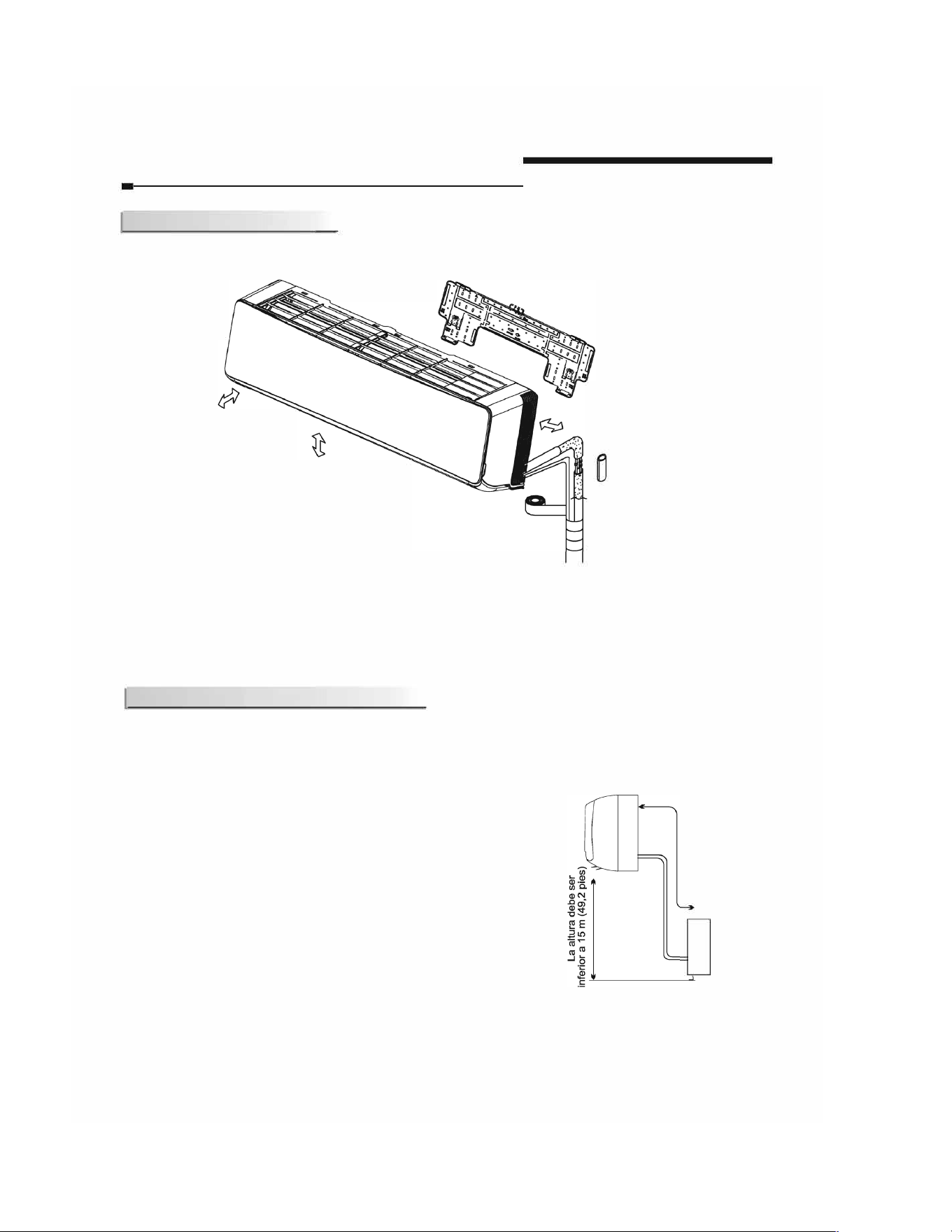
I Diagrama de instalaci6n
La distancia respecto a
la pared debe ser
superior a 50 mm/2
pulgadas.
La distancia respecto a
los obstaculos debe ser
superior a 3 m/9,8 pies.
La distancia respecto
al techo debe ser
superior a 200
mmn,9 pulgadas.
La distancia respecto al suelo
debe ser superior a
1
.8 m/
6
pies.
Unidad interior A
La distancia respecto a la pared
debe ser superior a 50 mm/2
pulgadas.
•
La gu anterior es solo una repsenci6n senca de la unidad, po no coespondee al aspecto exteo de la
unidad que ha compdo.
•
La instalaci6n debe reaae en conformidad con las normas nacionales de cableado y solo debe reaarla peonal
autoado.
! scciones de/ sitio
Lugar de instalaci6n de la unidad inteor:
• Donde no haya obstaculos cerca de la salida de aire y el aire pueda
llegar facilmente a todos los rincones.
• Donde pueda realizarse facilmente un orificio en la pared.
• Mantenga la separaci6n requerida desde la unidad hasta el techo y
la pared de acuerdo con el diagrama de instalaci6n de la pagina
anterior.
• Donde el filtro de aire pueda sustituirse facilmente.
• Mantenga la unidad y el mando a 1 m (3,28 pies) de distancia o mas
respecto a televisores, radios, etc.
• Tan alejada como sea posible de lamparas fluorescentes.
• No coloque nada cerca de la entrada de aire que obstruya la
absorci6n de aire.
•
I
nstale en una pared lo bastante fuerte para soportar el peso de la
unidad.
•
I
nstale en un lugar que no incremente el ruido y las vibraciones del
funcionamiento.
• Man
tengala apartada de la luz solar directa y de fuentes de calor.
No coloque materiales inflamables ni aparatos de combustion sobre
la unidad.
Unidad interior
La longitud de la tuberia es
la siguiente:
Para
9-
1
2
K y inferior a
9-
1
2
K: 20 mes (65,4
pie M. Para 18K y
superior a 18K: 30 mets
(98,4 pie Max.
Unidad exterior
L
La unidad interior debe estar mas
elevada que la unidad exterior.
La inslaci6n de la unidad intea se ree al manual de instalaci6n de la unidad extea.
-6-
ESPAÑOL
28
ESPAÑOL
29
ESPAÑOL
30
ESPAÑOL
31
ESPAÑOL
32
ESPAÑOL
33
ESPAÑOL
34
lnscciones de inslaci6n /
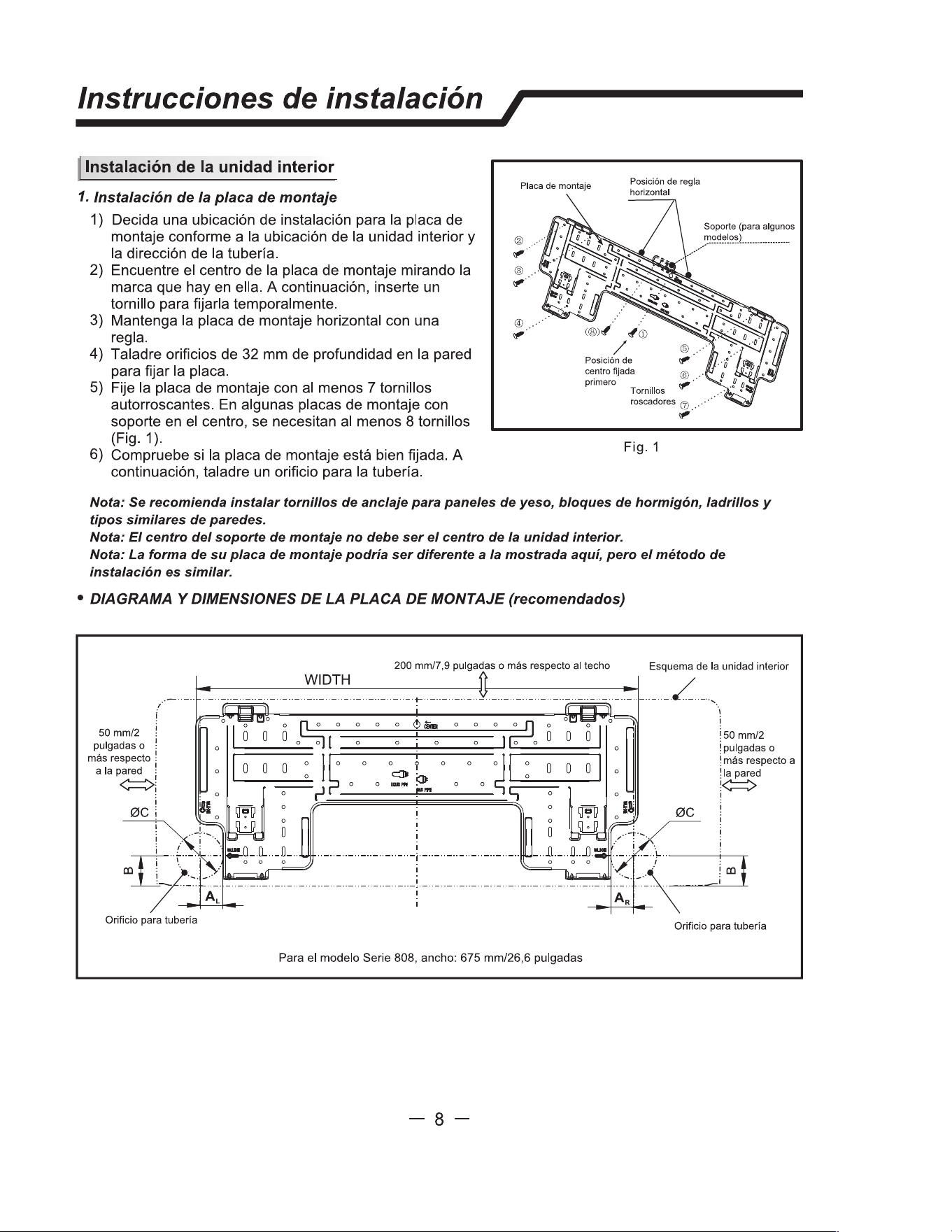
� lnstalacion de la unidad interior
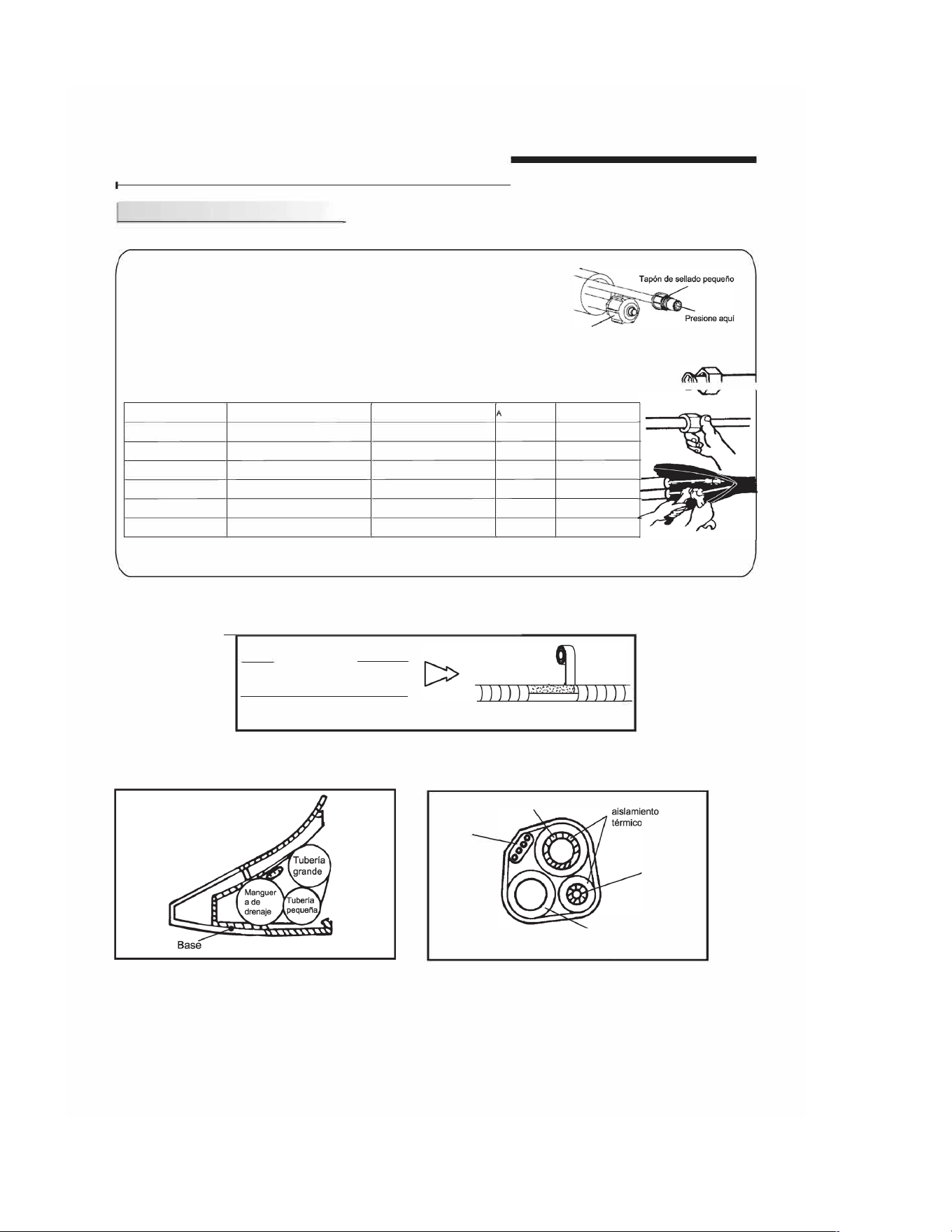
6) Conecte las tuberias.
Conexi6n de la tuberia:
a.Antes de desatornillar los tapones de sellado grande y pequeno, presione el
tap6n de sellado con el dedo hasta que el ruido de salida pare y, a continuaci6n,
suelte el dedo.
b.
Conecte las tuberias de la unidad interior con dos llaves. Preste especial
Tap6n de sellado grande
atenci6n al par permitido mostrado a continuaci6n para evitar que las tuberias,
los conectores y las tuercas c6nicas se dermen y resulten daadas.
c. Aprietelas previamente con los dedos primero y despues utilice las llaves.
�
Si no escucha el ruido de salida, p6ngase en contacto con el distribuidor.
� �-
Modelo
Tamano de la tuberia
Par
ncho de tuerca
Grosor min.
7
K-18K
Lado del lfquido (6 o 1/4)
15-20N·m o 11-15pies-libras
17 o 5/8
0.5 o 0.02
24K-36K
Lado del lfquido (9.53 o 3/8)
30-35N·m o 22-26pies-libras
22 o 7/8
0.6 o 0.024
7
K-12K
Lado del gas (9.53 o 3/8 )
30-35N·m o 22-26pies-libras
22 o 7/8
0.6 o 0.024
18K
Lado del gas (12 o 1/2 )
50-55N·m o 37-
41
pies-libras
24 o 0.94
0.6 o 0.024
24K-36K
Lado del gas (16 o 5/8)
60-65N·m o 44
-48pies-libras
27 o 1.1
0.6 o 0.024
36K
Lado del gas (19 o 3/4)
70-75N·m o 52-55pies-libras
32 o 1.26
1.0 o 0.039
NOTA: Las dimensiones son en "mm o pulgadas" a menos que se indique de otro modo en la tabla.
7) Despues de conectar las tuberias seg(m sea necesario, instale la manguera de drenaje. A continuaci6n,
conecte los cables electricos. Despues de conectarlos, envuelva las tuberias, los cables y la manguera
de drenaje con materiales de aislamiento termico (Fig. 15-Fig. 1
7)
.
Aislamiento termico
Envueltas con cinta de vinilo
Fig. 15
Nota: Envue/va las juntas de las tuberias con mate/es de aislamiento teico y despues
envuelvalas con cta de vinilo.
Fig. 16
Cable
electrico
Nota: Co/oque la manguera de naje bajos las tubes.
Tuberia grande
Fig. 17
Tubo de
Tuberia
pequena
Manguera de drenaje
(preparado por el
usuario)
Nota: matel de alamiento ua espuma de poetileno de mas de 6 mm de gsor.
Nota: El usuao ppa la mangue de drenaje.
Nota: Las cis de este manual pon fe de las de/ cmaador que ha seleccionado.
-13-
ESPAÑOL
35
ESPAÑOL

36
ESPAÑOL
37
lnstrucciones de instalaci6n /
I Alimentaci6n y cableado
Conectar el cable
o Unidad interior
Conecte el cable electrico con la unidad interior
conectando individualmente los cables a los terminales
del panel de control siguiendo la conexi6n de la unidad
exterior.
Precauci6n:
Panel frontal
Terminal (interior)
Unidad interior
Carcasa frontal
Las figuras de este manual estan basadas en la
vista externa de un modelo estandar. En
consecuencia, la forma podria diferir de la del
climatizador que haya seleccionado.
1.
Utilice siempre un circuito electrico individual para el climatizador. lgual que para el metodo de
cableado, consulte el diagrama del circuito incluido en el interior de la puerta de acceso.
2
. Confirme que el grosor del cable sea el especificado en la especificaci6n de la fuente de alimentaci6n.
3.
Compruebe los cables y asegurese de que esten ajustados con firmeza despues de conectarlos.
4. Asegurese de instalar un interruptor para fugas de tierra en una zona mojada o humeda.
pecificaci6n de /os cables
Capacidad (Btuh)
Cable de alimentaci6n
Tipo
Areas transversales
normales
7
K-12K(208/230V)
SJTW
4X14G
18K(208/230V)
SJTW 4X14G
24K-36K(208/230V) SJTW 4X14G
9K, 12K(115V)
SJTW 4X14G
Atenci6n:
El enchufe debe estar accesible incluso despues de instalar el aparato en caso de que sea
necesario desconectarlo. Si no fuera posible, conecte el aparato a un dispositivo
interruptor de dos polos con una separaci6n de contacto de al menos 3 mm colocado en
una posici6n accesible incluso despues de la instalaci6n.
-16-
ESPAÑOL
38
ESPAÑOL
El diagrama es solo de referencia; se deben seguir los terminales reales del producto.
39
ESPAÑOL
40
ESPAÑOL
41
ESPAÑOL
42
ESPAÑOL
43
ESPAÑOL
44
ESPAÑOL
45
ESPAÑOL
46
ESPAÑOL
47
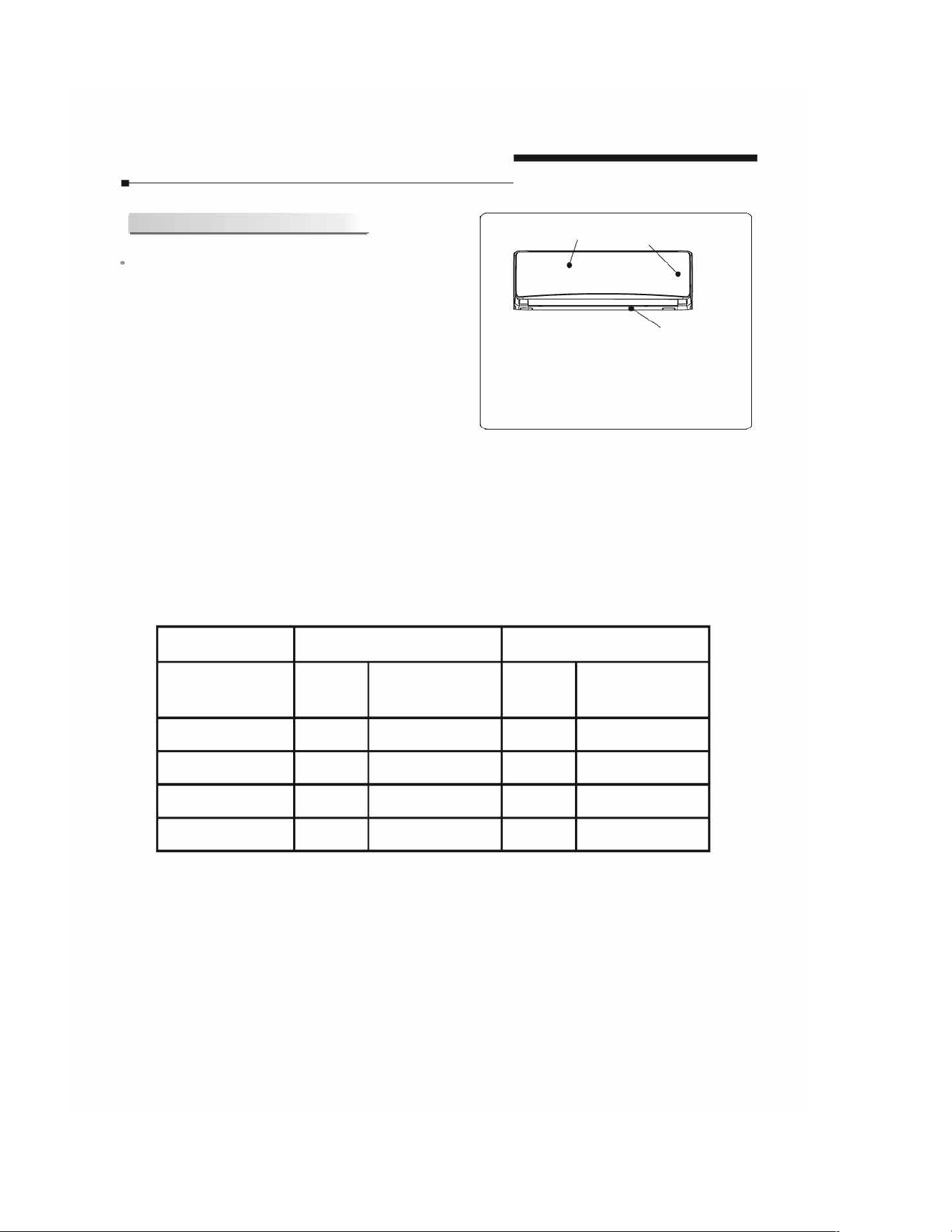
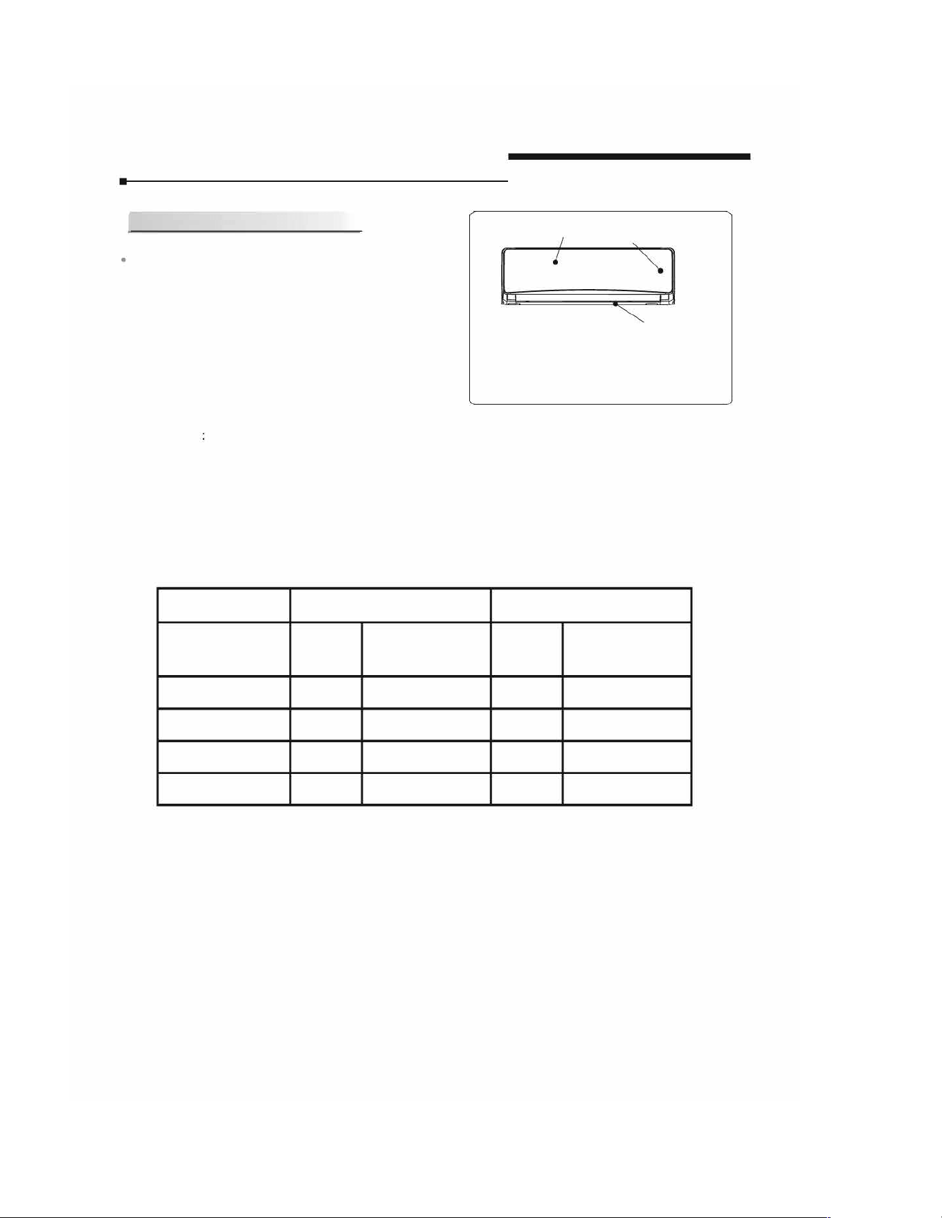
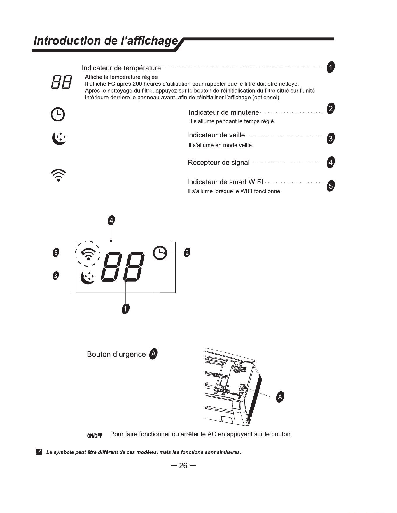
lntroducci6n a la pantaa /
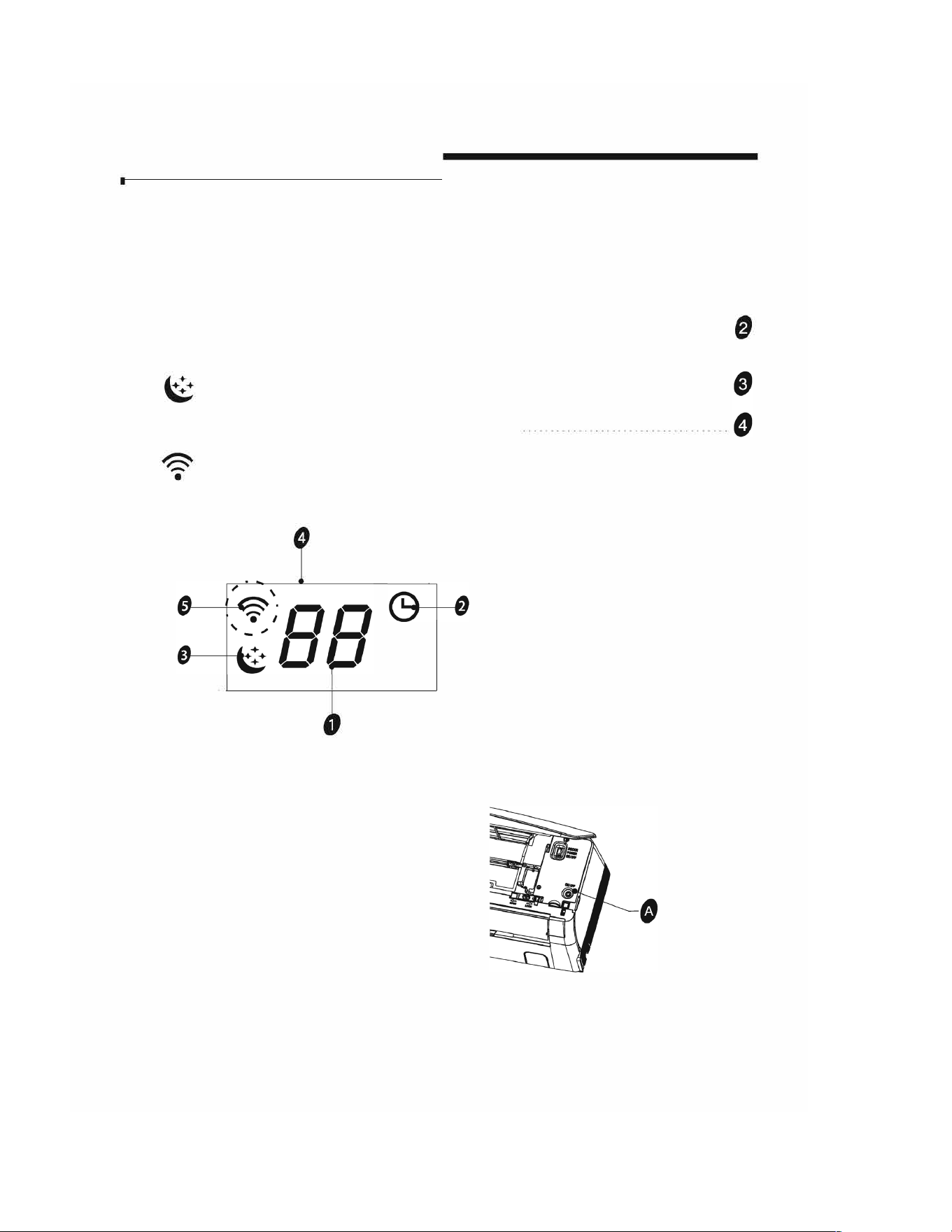
88
0
lndi
cado
r
de
t
emp
e
r
a
tur
a
· · · · · · · · ·
· · · · · · · · ·
· · · · · · · · · ·
· · · · · · · · ·
· · · · · · · · ·
· · · · · · · · ·
· · · ·
0
Ver la temperatura ajustada.
Muestra FC despues de 200 horas de uso coma recordatorio para limpiar el filtro.
Despues de limpiar el filtro, pulse el bot6n ubicado en la unidad interior tras el panel
frontal para restablecer la pantalla (opcional).
Muestra la temperatura establecida en modo de humedad (opcional).
lndicado
r
de
t
emp
o
r
i
z
ado
r
· · · · · · · ·
· · · · · · · ·
· · · · · · · ·
· · · · ·
Se ilumina durante el tiempo establecido.
lndicado
r
de
m
odo s
u
eno ............................. .
Se ilumina en modo Suspension.
R
e
c
e
pt
o
r
de se
a
l
lndicador de Wi-Fi inteligente
· · · · · · · · · · · · · · · · · · · · · · · · · · ·
Se ilumina cuando el Wi-Fi esta encendido.
�
Bot6n de emergencia 0
OFF
Para encender o apagar el AC, pulse el bot6n.
Los sbolos pueden ser difentes en estos modelos, pe las funciones son similas.
-26-
ESPAÑOL

48
49
Installation Manual
-
z
z
·
FRANÇAIS
50
FRANÇAIS
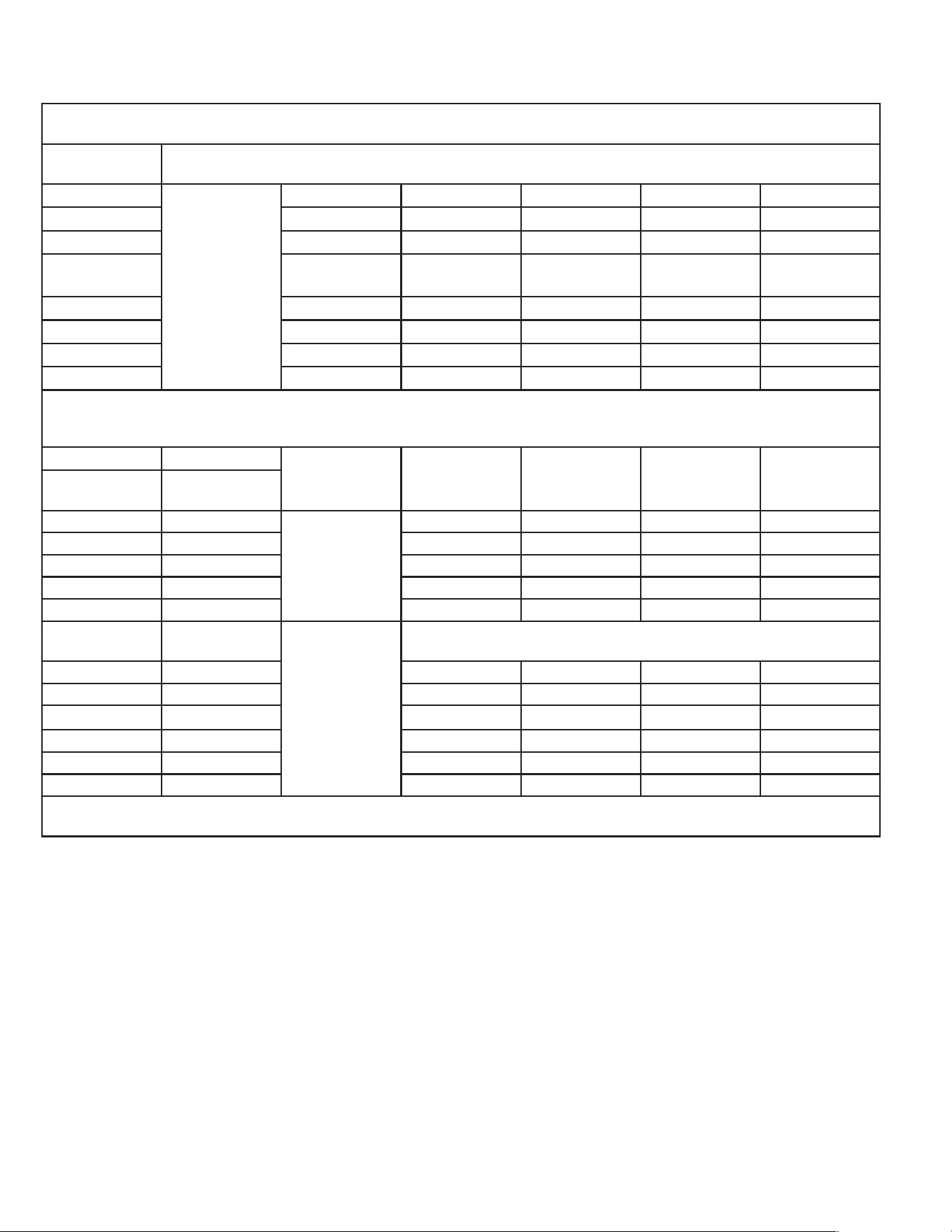
La taille minimale de la pièce (réfrigérant R-32 ou R-454B) est déterminée par la charge totale de réfrigérant dans le système. Utilisez ce tableau pour déterminer la
taille minimale de la pièce dans laquelle la tête intérieure peut être installée.
Une minute (pieds
carrés)
Hauteur d’installation (pieds et pouces)
Mc(oz) 6 6' 6" 7' 2" 7' 10" 8' 2"
64 71 64 58 53 51
65-71 78 71 64 59 57
72-77 86 78 71 65 62
78-85 94 85 77 71 68
86-92 102 92 83 77 74
93-99 110 99 90 82 79
100-106 117 105 96 88 85
Avant d’installer l’unité, utilisez le tableau ci-dessous pour déterminer la charge totale de réfrigérant de l’unité. Si la charge totale est inférieure à 64 oz. il n’y a
aucune restriction en matière de taille de pièce. Si la charge totale dépasse 64 oz. reportez-vous au tableau ci-dessus. Utilisez la charge totale, la hauteur du bas de
l’unité et le tableau ci-dessus pour déterminer la superficie minimale de la pièce dans laquelle l’unité
Mc(oz) Type de réfrigérant Précharge avec 25
pieds de jeu de lignes
25-50 ft 50-75 ft add 75-100 ft
Modèle d’unité
intérieure
Outdoor Unit Model
FAHSW09A1C FSHSR09B1C
R-32
21.2 27.7 33.2 N/A
FAHSW12A1C FSHSR12B1C 21.9 27.4 32.9 N/A
FAHFW18A3D FSHSR18B3D 45.9 51.4 56.9 62.4
FAHFW24A3D FSHSR24B3D 47.7 55.7 63.7 71.7
FAHSW36A3D FSHSR36B3D 72.4 83.2 93.9 104.7
FAHM07A3D Multi-zones
R-454B
Voir Multi-Zone Outdoor Condenser IOM Pour plus de détails sur la restriction de la taille de la
pièce et l’application du capteur A2L.
FAHSW09A1AC FPHSR09A1C 33.5 39 44.5 N/A
FAHFW09A3D FPHSR09A3D 35.3 40.8 46.3 N/A
FAHSW12A1C FPHSR12A1C
35.3 40.8 46.3 N/A
FAHFW12A3D FPHSR12A3D 38.1 43.6 49.1 N/A
FAHFW18A3D FPHSR18A3D 52.9 58.4 63.9 69.4
FAHFW24A3D FPHSR24A3D 70.6 78.6 86.6 94.6
Lors de l’ajout de réfrigérant au système pour un jeu de conduites supplémentaire, reportez-vous à la plaque signalétique du modèle et aux instructions d’installation
de l’unité extérieure pour connaître la quantité de charge appropriée.
51
FRANÇAIS
52
Instructions de securite
1
• 1. Pour garantir que l'unite nctionne normalement, veuillez lire soigneusement ce manuel
avant !'installation, et essayez d'eectuer !'installation strictement en conformite avec ce manuel.
• 2. Ne laissez pas d'air entrer dans le systeme de refrigeration ou le refrigerant se
decharger lorsque vous deplacez le climatiseur.
• 3.
Mettez convenablement a la terre le climatiseur.
• 4. Verifiez soigneusement les cables de connexion et les tuyaux, assurez-vous qu'ils
sont fixes de maniere correcte et ferme avant de mettre le climatiseur sous tension.
•
5. II doit y avoir un interrupteur pneumatique.
• 6. Ap res !'installation, le consommateur doit faire fonctionner le climatiseur correctement
conformement ace manuel, conserver un espace de stockage adapte pour la
maintenance et les deplacements ulterieurs du climatiseur.
•
7. Le fusible de l'unite :
Modele
Fusible de l'unite interieure
9K(115V)
T 3,15A ou T 5A 250 V
12K(115V)
T 3,15A ou T 5A 250 V
7K-12K(208/230V)
T 3,15A ou T 5A 250 V
18K(208/230V)
T 3,15A ou T 5A 250 V
24K-36K(208/230V)
T 3,15A ou T 5A 250 V
• 8. Un appareil de courant residue! (RCD) avec une valeur nominale superieure a 10 mA
evrait etre incorpore dans le cablage fixe conformement a la reglementation nationale.
•
9. At tention: Un risque de choc electrique peut provoquer des blessures ou un deces :
Deconnectez toutes les alimentations electriques a distance avant la mise en seice.
• 1 0. La meilleure longueur de tuyau de raccord entre l'unite interieure et l'unite exterieure
est inferieure a 7,5 m (24,6 pieds). Cela aectera l'eicacite du climatiseur si la distance
est superieure a cette longueur.
• 11 . Cet appareil electrique n'est pas prevu pour etre utilise par des personnes (y compris
des enfants) avec des capacites physiques, sensorielles ou mentales reduites, ou un manque
d'experience et de connaissance, a mains qu'elle soit supervisee ou guidee concernant
!'utilisation de l'appareil electrique par une personne responsable de leur securite. Les enfants
doivent etre surveilles par un adulte qui doit s'assurer qu'ils ne jouent pas avec l'appareil.
•
12. Cet appareil electrique peut etre utilise par des enfants ages de 8 ans et plus et des
personnes avec des capacites physiques, sensorielles ou mentales reduites, ou ayant un
manque d'experience et de connaissances a condition qu'elles soient supervisees ou
guidees concernant !'utilisation de l'appareil electrique de maniere sore et comprennent les
risques encourus. Les enfants ne devraient pas jouer avec l'appareil electrique. Le nettoyage
et l'entretien utilisateur ne devraient pas etre
eectues par des enfants sans supervision.
• 13. Les piles dans la telecommande doivent etre recyclees ou eliminees correctement.
Elimination des piles usagees -- - Veuillez vous debarrasser des piles au point de
collecte accessible mis en place pour les dechets municipaux.
-1-
FRANÇAIS
53
FRANÇAIS
54
FRANÇAIS
55
FRANÇAIS
56
FRANÇAIS
57
_
i
n
_
s
_
t
_
�
_
u
_
c
_
_
o
_
n
_
s
_
d
_
'
_
in
_
s
_
t
_
a
_
_
a
_
_
o
_
n
__ /
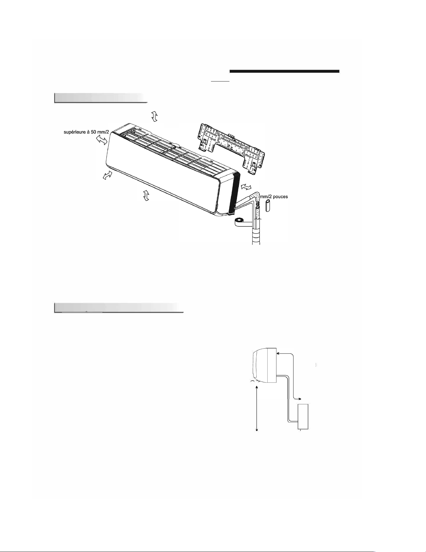
Schema d'installation
La distance depuis
l'obstacle devrait etre
pouces
La distance depuis l'obstacle
devrait etre superieure a 3
m/9,8 pieds.
La distance a partir du
sol devrait etre
superieure a
1
.8 m/
6
pieds
La distance depuis
!'obstacle devrait etre
superieure a 200 mm/7,9
pouces
La distance depuis le mur
devrait etre superieure a 50
Unite lnterieure A
• Le schema ci-dessus est une representation simplifiee de l'appareil; ii se peut qu'il ne concide pas precisement
avec la machine que vous avez achetee.
• L'installation doit etre effectuee conformement aux Reglementations Nationales en vigueur, exclusivement par
du personnel qualifie.
Consignes
relatives au site
Site destine a accueillir /'unite interieure
•
1. Partout ou ii n'existe aucun obstacle susceptible d'encombrer la sortie
d'air et que l'air peut etre expulse sans diiculte.
• 2. Partout ou des conduites peuvent etre installees et des trous perces
dans les murs.
• 3. Laissez m'espace necessaire entre le plafond et l'appareil, et l'appareil
et le mur, tel que cela est montre sur le diagramme de la page precedente.
• 4.Partout ou le filtre a air peut etre retire sans diiculte.
•
5. Maintenez l'appareil ainsi que la telecommande
a 1 m (3,28pieds)
minimum de la television, radio etc.
• 6. Maintenez l'appareil eloigne au maximum des lampes fluorescentes.
•
7. Ne rien placer devant l'entree d'air.
• 8. lnstallez l'appareil sur un mur suisamment solide pour supporter le
poids de l'appareil.
•
9. lnstallez le dispositif dans un lieu ou les bruits et les vibrations ne
risquent pas d'etre amplifies.
•
10. Tenez
a l'ecart des rayons directs du soleil et des sources de chaleur.
Ne placez pas de materiaux inflammables ni d'appareils
a combustion
sur le dessus de l'appareil.
·
�
��
E
�
,
�
j-�
•
Unite interieure
La longueur du tuyau est
la suivante
Pour
9-
1
2
K et mains de
9-
1
2
K:
20 mets (65,4 pi) Max
.
Pour 18K et plus de 18K:
30 mets 8,4 pi) Max.
Unite
exterieure
£�-----�
L
L'unite interieure est plus
haute que l'unite exterieure
Pour le montage de /'unite exterieure, faites rerence au manuel de montage de /'unite exterieure.
-6-
FRANÇAIS
58
FRANÇAIS
59
FRANÇAIS
60
FRANÇAIS
61
FRANÇAIS
62
FRANÇAIS
63
FRANÇAIS
64
Instructions d'instaon /
�
Installation de l'unite interieure
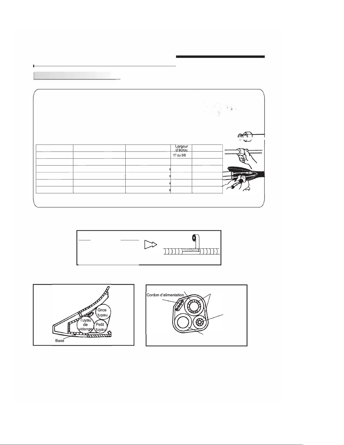
6) Connectez les tuyaux
Connexion du tuyau :
Pe
a.Avant de devisser les couvercles de scellage grand et petit, appuyez sur le petit �:::
couvercle avec le doigt jusqu'a ce que le bruit d'evacuation s'arrete, puis
relachez le doigt.
Appuyez ici
b. Connectez les tuyaux de l'unite interieure avec deux cles. Faites particulierement
G
attention au couple admis comme illustre ci-dessous pour empecher les tuyaux,
d
ros
f
se ca
t
psule
I t t I d
.
d'"t d -� , t d
•
e erme ure
es connec eurs e es raccor s cornques
e re e,ormes e en ommages.
c. Previssez-les a la main d'abord, puis utilisez les cles.
Si vous n'entendez pas le bruit de l'echappement, veuillez contacter le vendeur.
� �-
Modale Taille du tuyau Couple
Epaisseur min.
7
K-18K
COie liquide ( 6 mm ou 114 de pouce)
15-20N·m ou11-15 pieds-livres
0.5
OU 0.02
24K-36K
COie liquide ( 9.53 mm au 318 de pouce)
30-35N·m ou 22-26 pieds-livres
22
OU 7/8
0.6
OU 0.024
7
K-12K
cOte gaz ( 9.53 mm ou 3/8 de pouce)
30-35N·m ou 22-26 pieds-livre
22
OU 7/8
0.6
OU 0.024
18K
cote gaz ( 12 mm ou 112 de pouce
50-55N·m ou 37-41 pieds-livre
24
OU 0.94
0.6
OU 0.024
24K-36K
cOte gaz ( 16 mm ou 518 de pouce)
60-65N·m ou 44-48 pieds-livre
27 ou1.1
0.6
OU 0.024
36K
cOte gaz ( 9.53 mm ou 3/8 de pouce)
7 0-75N·m ou 52-55 pieds-livre
32
OU 1.26
1.0
OU 0.039
REMARQUE: Les dimensions sont en« mm ou pouce », sauf si declare autrement dans le tableau
7)Apres raccordement des tuyaux comme necessaire, installez le tuyau de vidange. Connectez ensuite
les cordons d'alimentation. Apres connexion, enveloppez ensemble la tuyauterie, les cordons et le tuyau
de vidange avec des materiaux thermiques d'isolation (fig.15
a fig.17).
Isolation thermique
enveloppe dans un type de vinyle
Fig. 15
Remarque : Enveloppez /es join de tuyautee avec des materia d'isolation eique et ensuite
enve/oppez-les avec un ruban en ne.
Gros tuyau
Fig. 16
Remarque : Placez le tu de ge sous /es t
Tube d'isolation thermique
Fig. 17
Petit tuyau
Tuyau de vidange
(prepare par l'utilisateur)
Remarque : Le mateu d'isolation ue de la mousse de polyeene de plus de 6 mm d'epaisseur.
Remarque : Le tuyau de dange est pa par l'utsateur.
Remarque : Les us dans ce manuel peuvent dierer de
celle du cmaeur que vous avez seleconne.
-13-
FRANÇAIS
65
FRANÇAIS
66
FRANÇAIS
67
Inscons d'installaon
/
II Alimentation et cablage
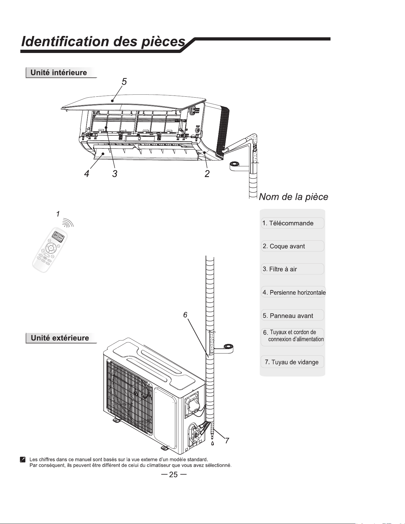
Connon du cable
o Unite interieure
Connectez le cordon d'alimentation a l'unite interieure
en connectant les cables aux terminaux sur le panneau
de controle de maniere individuelle conformement
a la
connexion de l'unite exterieure.
Mise en garde
Panneau avant
Terminal(interieur)
Unite interieure
Coque avant
Les chires dans ce manuel sont bases sur la vue
eerne d'un modele standard. Par consequent, ils
peuvent tre dierent de celui du climatiseur que
vous avez selectionne.
1. Ne manquez jamais d'avoir un circuit electrique individual specifiquement pour le climatiseur. Concernant la
methode de cablage, referez-vous au diagramme de circuit publie a l'interieur de la porte d'acces.
2. Confirmez que l'epaisseur de cable est comme specifiee dans les specifications de la source d'alimentation electrique.
3. Verifiez les cables et assurez-vous qu'ils sont bien serres apres la connexion du cable.
4. Assurez-vous d'installer un disjoncteur a courant de fuite a la terre dans les zones humides.
Specications du cable
capacite (Btuh)
Cordon d'alimentation
Rallonge du cordon
d'alimentation
Zones normales
Type
de section
transversale
7
K-12K(208/230V)
SJTW
4X14G
18K(208/230V)
SJTW
4X14G
24K-36K(208/230V) SJTW
4X14G
9K,12K(115V)
SJTW
4X14G
Attention:
La che doit etre accessible meme apres nsation de l'appare, au cas o ii serait necessa
de le debncher. Si ce n'est pas possible, connectez l'appail elecque a un positif de
commutaon bipolaire avec une sepaon de contact d'au moins 3 mm place dans une posion
accessle meme apres insation.
-16-
FRANÇAIS
68
FRANÇAIS
Le diagramme est uniquement une référence, les bornes réelles du produit doivent être suivies.
69
FRANÇAIS
70
FRANÇAIS
71
FRANÇAIS
72
FRANÇAIS
73
FRANÇAIS
74
FRANÇAIS
75
FRANÇAIS
76
FRANÇAIS
77
FRANÇAIS
