OPERATOR’S MANUAL
For the dealer nearest you, consult our web page at www.wmaze.com
CLB-603
TREAT AND RECYCLE
ADD ONS: ■ CLB-30 ■ CLT-300 ■ CLT-600
8.914-458.0 - G
05/22/18

CONTENTS
2
8.914-458.0-G • Water Maze CLB-603
Introduction and Important Safety Issues ..................................................................... 4-5
How the Bio-System Works ..........................................................................................6, 7
Consumables ....................................................................................................................7
Operating Environment .....................................................................................................7
Operating Tips ..................................................................................................................7
Bio-System Component Identifi cation .......................................................................... 8-9
Installation Instructions ................................................................................................9-11
Start-up ...........................................................................................................................12
CLB-603 Installation View with Optional CLT-300 ..........................................................13
CLB-603 Installation View ..............................................................................................14
CLB-603 Electrical Installation View ...............................................................................15
CLB-603 Water Panel Installation...................................................................................16
CLB Control Panel ..........................................................................................................17
Piping Connection Diagram #1 and Table ................................................................ 18-19
Piping Connection Diagram #2 and Table ................................................................ 20-21
Piping Connection Diagram #3 and Table ................................................................ 22-23
Electrical Field Connection CLB-603A Diagram and Table ...................................... 24-25
Air Connection Diagram .................................................................................................26
Recycle Holding Tank Installation ...................................................................................27
Metering Pump Operation ..............................................................................................28
Metering Pump Maintenance ..........................................................................................29
Metering Pump Exploded View and Parts List ...............................................................30
Pressure Switch and Pressure Tank Operation ..............................................................31
Ozone Generator ...................................................................................................... 32-34
Optional pH Digital Controller Model 240 .......................................................................36
Troubleshooting - pH Sensor ..........................................................................................37
Troubleshooting - Infeed, Ozone and Transfer Pump.....................................................38
Troubleshooting - Pump .................................................................................................39
Troubleshooting - Pump Motor .......................................................................................40
Troubleshooting - Water Solenoid ..................................................................................41

3
CONTENTS
Part Number ______________________________
Serial Number ______________________________
Date of Purchase ___________________________
The part and serial numbers will be found on a decal attached to the machine.
You should record both serial number and date of purchase and keep in a safe
place for future reference.
8.914-458.0-G • Water Maze CLB-603
Troubleshooting - Water Seals .......................................................................................42
CLB Maintenance ..................................................................................................... 43-44
CLB-603 Component Assembly Exploded View & Parts List ................................... 45-46
CLB-603 Air Stone Assembly Exploded View and Parts List .................................... 47-48
CLB-603 Infeed Pump Assembly Exploded View & Parts List ................................. 49-50
CLB-603 Transfer/Ozone Pump Assembly Exploded View
& Parts List ............................................................................................................... 51-52
CLB-603 Drain Surge Tank Exploded View & Parts List ........................................... 53-54
CLB-603 Air Components Exploded View & Parts List ............................................. 55-56
CLB-603 Manifold Assembly Exploded View & Parts List ........................................ 57-58
Water Panel Exploded View & Parts List .................................................................. 59-60
CLB-603 Control Panel Exploded View & Parts List ................................................ 61-62
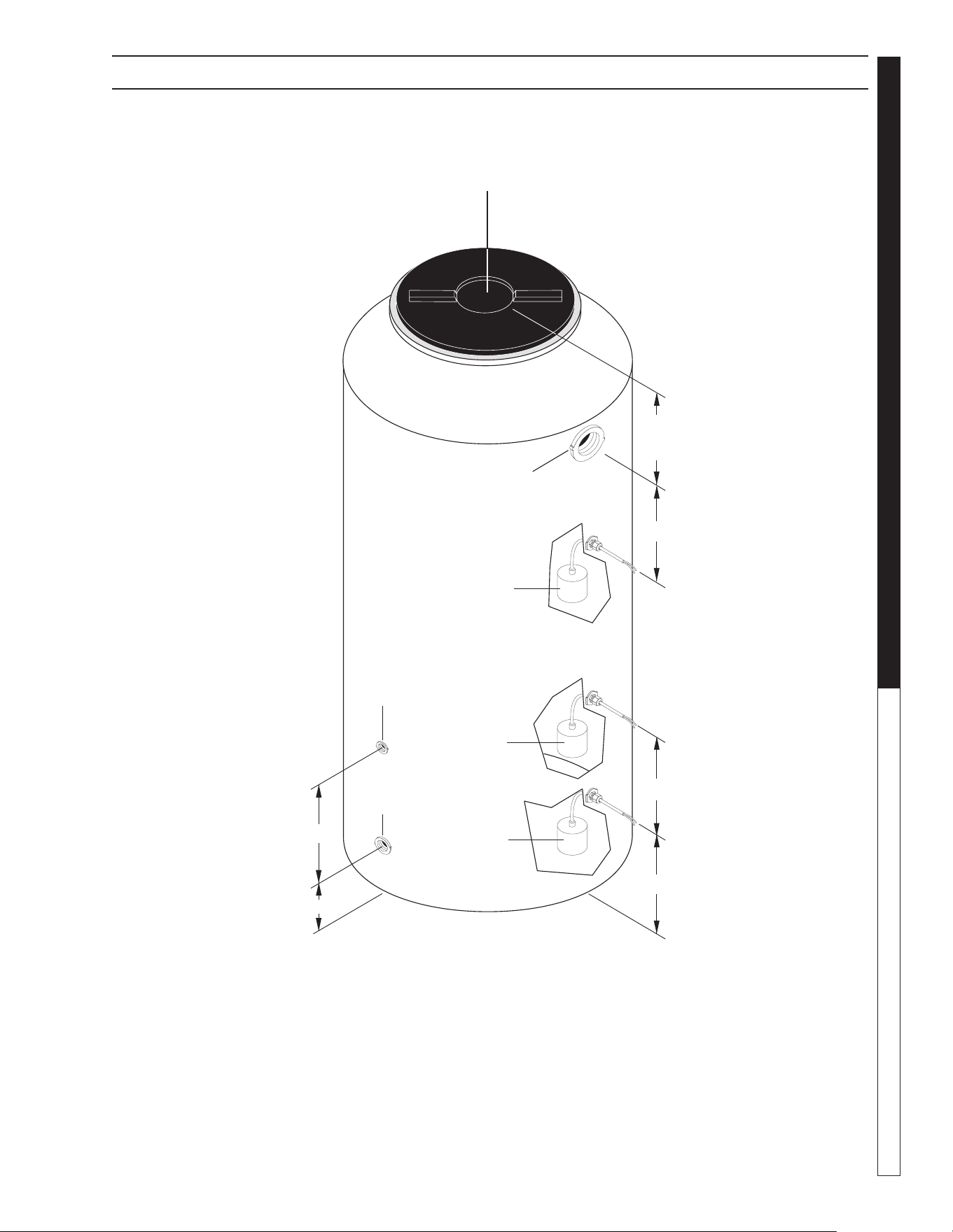
CLB-603 Dimension Locations of Tank Connections .....................................................63
Ozone Generator Exploded View & Parts List ................................................................64
CLB-30 Auxiliary Digester Assembly Exploded View & Parts List ............................ 65-68
CLT-300 Tank Assembly Installation Exploded View & Parts List ............................. 69-70
CLT-300 Tank Assy Options Exploded View & Parts List ......................................... 71-72
CLT-600 Tank Assembly Exploded View & Parts List ............................................... 73-74
Oil Skimmer Assembly Exploded View and Parts List .............................................. 75-76
Ozone Filter Pump Exploded View & Parts List .............................................................77
Optional Transfer Pump Exploded View & Parts List .....................................................78
Transfer Pump Exploded View & Parts List ....................................................................79
Infeed Pump Exploded View & Parts List .......................................................................80
Warranty
8.914-458.0-G • Water Maze CLB-603
OPERATOR’S MANUAL WATER TREATMENT SYSTEM
4
Your owner’s manual has been prepared to provide you with a
simple and understandable guide, for equipment operation and
maintenance, based on the latest product information available at
the time of printing. To keep your machine in top running condition
follow the specifi c maintenance and troubleshooting procedures
given in this manual. When ordering parts please specify model
and serial number.
NOTE: WATER MAZE reserves the right to make changes
at anytime without incurring any obligations.
Owner/User Responsibility:
The owner and/or user must have an understanding of the manu-
facturer’s operating instructions and warnings before using this
pressure washer. Warning information should be emphasized and
understood. If the operator is not fl uent in English, the manufactur-
er’s instructions and warnings shall be read to and discussed with
the operator in the operator’s native language by the purchaser/
owner, making sure that the operator comprehends its contents.
Owner and/or user must study and maintain for future reference
the manufacturers’ instructions.
SAVE THESE INSTRUCTIONS
This manual should be considered a permanent
part of the machine and should remain with it if
machine is resold.
When ordering parts, please specify model and
serial number. Use only identical replacement
parts. This machine is to be used only by trained
operators.
WARNING: When using this
machine basic precautions
should always be followed,
including the following:
CAUTION: To reduce the risk of
injury, read operating instruc-
tions carefully before using.
1. Read the owner's manual thoroughly.
Failure to follow instructions could cause
malfunction of the machine and result in death, serious bodily injury
and/or property damage.
2. Know how to stop this product and bleed pressures quickly. Be
thoroughly familiar with the controls.
3. Stay alert - watch what you are doing.
WARNING: Ground system be-
fore connecting to the power
supply.
AVERTISSEMENT: Mettre le
système à la masse avant
de le raccorder à la source
d'alimentation.
WARNING: Wire the system for correct voltage.
See “Electrical” section of this manual and motor
nameplate.
AVERTISSEMENT: Raccorder le système au ré-
seau électrique en respectant la tension. Consulter
la section « Électricité » du présent manuel et la
plaque signalétique du moteur.
WARNING: Meet the National
Electrical Code and local codes
for all wiring.
AVERTISSEMENT: Respecter le
Code national de l'électricité et
les codes locaux pour tous les
câblages.
WARNING: Follow the wiring
instructions in this manual
when connecting the system
to the power lines.
AVERTISSEMENT: Suivre les instructions de
câblage dans le présent manuel au moment de
raccorder le système aux lignes de transport
d'électricité.
WARNING: All wiring must be performed by a
qualifi ed electrician.
AVERTISSEMENT: Tout le câblage doit être eff ec-
tué par un électricien qualifi é.
4. Know the system application, limitations, and potential haz-
ards.
WARNING: Do not use to pump concentrations
of fl ammable or explosive fl uids such as gaso-
line, fuel oil, kerosene, etc. Do not use in explo-
sive atmospheres. Pumps should only be used
with liquids compatible with pump component
materials. Failure to follow this warning can re-
sult in personal injury and/or property damage.
AVERTISSEMENT: Les pompes devraient être utili-
sées uniquement avec des liquides compatibles
avec les matériaux des composants des pompes.
Le non-respect des précautions peut mener à
des lésions corporelles et/ou des dommages à la
propriété.
5. WARNING: Risk of electric shock.
AVERTISSEMENT: Risque de choc électrique
All wiring should be performed by a qualifi ed
electrician.
6. Never make adjustments on the machine while it is in opera-
tion, except for those prescribed in this manual.
WARNING
KEEP WATER SPRAY
AWAY FROM
ELECTRICAL
WIRING.
WARNING
READ OPERATOR’S
MANUAL
THOROUGHLY
PRIOR TO USE.
INTRODUCTION & IMPORTANT SAFETY INSTRUCTIONS
WARNING
RISK OF EXPLOSION:
DO NOT SPRAY
FLAMMABLE LIQUIDS.

8.914-458.0-G • Water Maze CLB-603
5
WATER TREATMENT SYSTEM
OPERATOR’S MANUAL
7. The main power must be brought from the circuit breaker and
wired into the electrical box on the CLB. This line must be run
through conduit to protect it from damage. A power discon-
nect should be located next to the machine for maintenance
purposes.
8. Before servicing the machine, refer to all the MSDS’s on the
material identifi ed in the wastestream. You must comply with
all warnings and wear all protective clothing as stated on the
MSDS’s.
9. Protect all electrical cords from sharp objects, hot surfaces,
oil, sunlight, and chemicals. Avoid kinking the cords. Replace
or repair damaged or worn cords immediately. All wiring
should be run through conduit.
10. Inlet water temperature must not exceed 85°F.
11. Disconnect the power before servicing this machine. If the
power disconnect is out of sight, lock it in the open position
and tag it to prevent unexpected application of power.
12. The best insurance against an accident is precaution and
knowledge of the equipment.
13. WATER MAZE is not liable for modifi cations or use of
components not purchased from WATER MAZE.
14. Personal Safety:
a. Wear safety glasses and other applicable protective
clothing at all times when working on this machine.
Refer to item #6 under Important Safety
Information.
b. Keep your work area clean, uncluttered and properly
lighted. Replace all unused tools and equipment.
c. Keep visitors at a safe distance from work area.
d. Make the workshop safe with padlocks and master
switches.
15. Running the system without water will damage the pumps
and will void the warranty.
16. Release all pressure within the system before servicing any
component.
17. Drain all liquids from the component before
servicing.
18. Check hoses for weak or worn conditions before each use,
making certain that all connections are secure.
19. Periodically inspect pump and system components. Perform
routine maintenance as required.
20. Do not touch an operating motor. Modern motors are de-
signed to operate at high temperatures.
21. Do not handle a pump or pump motor with wet hands, when
standing on a wet or damp surface, or in water.
IMPORTANT SAFETY INSTRUCTIONS
22. The pump motors are equipped with an automatic resetting
thermal protector and may restart unexpectedly. Tripping is
an indication of motor overloading as a result of operating
the pumps at low heads (low discharge restriction), exces-
sively high or low voltage, inadequate wiring, incorrect motor
connections, or a defective motor or pump.
23. IMPORTANT NOTE: The sump pump is not a trash pump
and is subject to premature failure unless sump pit baffl ing
or additional protection is provided.
24. Keep machine from freezing.
25. Do not spray water directly at machine.
WARNING: The Bio-System contains moving parts
in the control center and in the pumps. Follow
safe practices when performing maintenance and
when troubleshooting the Bio-System. Set circuit
breakers to the off position when working on elec-
trical equipment. Use proper lockout and tag out
procedures when setting the breakers.
AVERTISSEMENT: Le Bio-System contient des
pièces mobiles dans le centre de contrôle et dans
les pompes. Suivre les pratiques de sécurité au
moment d'eff ectuer des opérations d'entretien et
lors de la correction des erreurs. Régler les dis-
joncteurs en position d'arrêt au moment d'eff ectuer
des opérations d'entretien sur l'équipement élec-
trique. Utiliser des procédures de verrouillage et
d'étiquetage appropriées au moment d'enclencher
les disjoncteurs.
WARNING: If any cords or electrical wires appear
to be frayed, damaged, or in poor condition, pro-
ceed with caution and immediately take steps to
have the cords repaired or replaced.
AVERTISSEMENT: Si un cordon ou des fi ls élec-
triques semblent effi lochés, endommagés ou en
mauvais état, agir avec prudence et prendre im-
médiatement des mesures afi n que les cordons
soient réparés ou remplacés.
WARNING: Make sure to take precautions when
performing maintenance on the pump in the catch
basin. Turn off the power to the pump and make
sure electrical cords are well maintained.
AVERTISSEMENT: S'assurer de prendre les pré-
cautions nécessaires au moment d'eff ectuer des
opérations d'entretien sur la pompe. Mettre la
pompe hors tension et s'assurer que les cordons
électriques sont bien entretenus. dans le bassin
collecteur.

8.914-458.0-G • Water Maze CLB-603
OPERATOR’S MANUAL WATER TREATMENT SYSTEM
6
HOW THE BIO-SYSTEM
WORKS
The Bio-System is an industrial grade microbial treatment sys-
tem, with modular components, that employs naturally occurring
microbes to treat waste water with characteristics that include
organic compounds (i.e., emulsifi ed oils and hydrocarbons). A
typical application may include treatment of wash water generated
from equipment washing (i.e., washing golf course maintenance
equipment, fork lift repair, truck wash etc.).
As compared to other water treatment technologies, microbial
treatment is highly dependent on maintaining a healthy environ-
ment for the microbes that perform the job of digesting organic
substances and converting them to carbon dioxide and water.
Some of these life sustaining considerations are:
• pH of the water (should be between 6.0 and 9.0)
• water temperature (should be above 40°F and below 120°F)
• adequate nutrient & food supply within the water (consult
with Water Maze) and
• adequate levels of dissolved oxygen (enough
dissolved oxygen to overcome the consumption rate /oxygen
demand).
In addition to the above considerations, the effl uent water quality
from a Bio-System will be subject to the concentration levels of the
organic matter in the untreated water and the relative dwell time
required for microbial digestion. Based on these factors, waste
waters with consistent concentration levels of organic matter will
be more predictable in terms of effl uent water quality. Conversely,
waste waters with fl uctuating concentration levels of organic matter
may vary in terms of effl uent water quality.
IMPORTANT NOTE: Subject to the application and desired
water quality requirements, processed water from a Bio-System
may require additional post-treatment.
IMPORTANT NOTE: Recycled water quality is dependent
upon many factors, including, but limited to the above consider-
ations and should be tested to assure that the water quality meets
the intended reuse.
IMPORTANT NOTE: Local regulations may limit what you
can do with water that is discharged from the Bio-System or may
require specifi c permits. Check with local authorities if you are
unsure about the uses or disposition of the water discharged by
the Bio-System. Regulations may also limit the use of a wash pad
as a mix and load station.
WARNING: The Bio-System is not designed to
produce potable water. Do not use water from
Bio-System for drinking or washing humans or
animals.
AVERTISSEMENT: Le Bio-System n'est pas conçu
pour produire de l'eau potable.
A typical Bio-System may be confi gured as a Treat & Discharge
System, or as a Treat & Recycle System. In either case, a properly
confi gured system may consist of one or more components (See
Bio-System Component Identifi cation pages). As in all properly
designed water treatment systems, Water Maze highly recom-
mends that appropriate pretreatment technologies be applied to
the waste water for the purpose of enhancing the performance
of the Bio-System. Some typical pretreatment technologies may
include: oil -skimming to remove "free-oils", heavy solids removal;
pH control; water temperature control; grass clipping removal;
inorganic material removal (i.e., heavy metals); etc. A few pretreat-
ment technologies are contained within this operator's manual (i.e.
CLT-300; Hydro-Screen, Debris Dumpster, etc.). For additional
pretreatment recommendations for your application, please consult
an authorized Water Maze representative.
The CLB-603 model (for recycle applications) typically works as
follows:
• The CLB-603 is the primary digester that houses the microbial
colony and is the primary control center for the system.
• The in-feed transfer pump (mounted on the
CLB-603 platform) draws pretreated water from the
pit system or from a pretreatment feed tank
(i.e., CLT-300 tank), and fi lls the 600-gallon digester tank. A
control fl oat is supplied with the CLB-603 unit. NOTE: See
in-feed pump curve for maximum lift capacity.
• The in-feed pump also acts to circulate water during the
off-hours. A pin-type timer allows the operator to control the
frequency and duration for circulation.
• Water being circulated will be sourced from inside the top portion
of the CLB-603, or from the last above ground tank connected
to the CLB-603 digester (e.g., this could be the last of multiple
CLT-600 tanks plumbed in series).
• During the timed circulation, an air-actuated directional control
valve blocks new (untreated) waste water from entering the
CLB-603 digester.
• If the application requires pH adjustment, an optional pH
control may be employed as the untreated water is transferred
into the CLB-603.
• On a routine basis (once each day) microbes and nutrients
(if required) are automatically injected into the CLB-603
tank. This is done to assure that the microbe population
(colonized within the bio-fi lm contained inside the CLB tank)
is maintained at maximum levels.
• Dissolved oxygen is maintained using a unique delivery
system.
• The CLB-603 incorporates a propriety 600-gallon cone-
bottom tank with a 55 degree slope that allows for easy solids
removal using an air-actuated timer-controlled purge valve.
• Subject to the application requirements, additional above-
ground holding tanks (CLT-600), or auxiliary digesters (CLB-
30) may be coupled in series to the CLB-603 digester.
HOW THE BIO-SYSTEM WORKS

8.914-458.0-G • Water Maze CLB-603
7
WATER TREATMENT SYSTEM
OPERATOR’S MANUAL
• Processed water gravity fl ows into a holding tank (not sup-
plied as part of a CLB-603), which should be sized based on
application requirements.
• The processed water holding tank will house control fl oats
that control fresh water make-up, excess water discharge,
the recycled water transfer pump, and the ozone circulation
pump.
• For polishing the water for recycle purposes, the CLB-603
includes a 4-tube UV ozone generator with injector, circulation
pump and timer.
• Upon demand of the operator or via the excess water fl oat
control, water contained inside the process water holding
tank is delivered through a pressurized manifold system.
• As water returns into the pretreatment system, the process
of treatment begins again.
CONSUMABLES
Microbes and Nutrients
BioStax 1800: Liquid Bacteria Concentrate
Part # 8.718-919.0 BioStax, 1800, 8 oz. vials, 2 part mix, part A and
B. It is an environmentally friendly, non-toxic and non-pathogenic
liquid concentrate. Controls odor, reduces oils and greases, other
hydrocarbons, animal fats and vegetable oils. Two 8 oz. bottles
pack A & B makes 5 gals.
BioStax 100: Hawaiian Blend Liquid Bacteria
Concentrate
Part # 8.718-917.0 comes in an 8 oz. bottle and works the same
as BioStax 1800 except that it is for use in Hawaii. One 8 oz.
bottle makes 5 gallons.
Bio Nutrient: Powder Bacteria Nutrient Source
Part # 8.718-916.0 comes in an 8 oz bottle and easily mixes in
water to make 5 gallons. It is introduced into the Bio-System
along with the bacteria to enhance the growth and effectiveness
of the biology.
The Bio-System is designed to work in a wide variety of operating
conditions. In normal operating environments, the Bio-System
should perform as specifi ed. In extremely hot or cold environments
certain precautions need to be taken.
Operating Conditions
Air Temperature Range 40° - 120°F
Treatable Waste Water contaminated
with hydrocarbons and
organic material
Water pH 6.0 - 9.0
Cold Weather
Protect the Bio-System from damage that can occur when freezing
water expands. Freezing water may cause pipes leading from the
catch basin to your Bio-System tanks to burst. Plus, the microbes
in the BioStax 1800 may not survive if they are frozen.
Drain all external pipes if a prolonged hard freeze is expected.
Make sure all valves (including the valve controlling the fl ow of
water to the hose connected to the hydro-screen) are open so
water can completely drain from the system. Disconnect the pump
in the catch basin (sump) using the camlock and drain the pump
and pipes. The pump may be left in or near the sump and doesn’t
need to be disconnected from the electrical system. In extreme
weather conditions also drain the Bio-System, using the drain
valves at the bottom of each tank.
In order to restart your Bio-System, you will need to reinoculate
your system with BioStax 1800 at start-up. The recommended
amount of BioStax 1800 for start-up is fi ve 8 oz. bottle sets, part
A & B, for a Bio-System system. Contact WATER MAZE for
specifi c instructions to restart your Bio-System.
Hot Weather
Your Bio-System may encounter minor problems, such as a slight
increase in odor, when operating in extremely hot temperatures in
excess of 100° F. If odor is a problem, add water to the system
on a daily basis by running tap water into the catch basin (sump).
The sump pump will automatically add the water to the system.
OPERATING TIPS
Your Bio-System is extremely simple to operate. Simply wash your
equipment or vehicles as you would normally.
• In extremely dirty environments, you may want to “pre-clean”
your equipment with air or with a brush, removing grass
directly to debris dumpster.
• Use hose end sprayers with automatic shutoffs when wash-
ing equipment so as to not exceed the peak capacity of your
Bio-System.
• Perform the daily, weekly and monthly service as described
on the maintenance pages.
OPERATING ENVIRONMENT
8.914-458.0-G • Water Maze CLB-603
OPERATOR’S MANUAL WATER TREATMENT SYSTEM
8
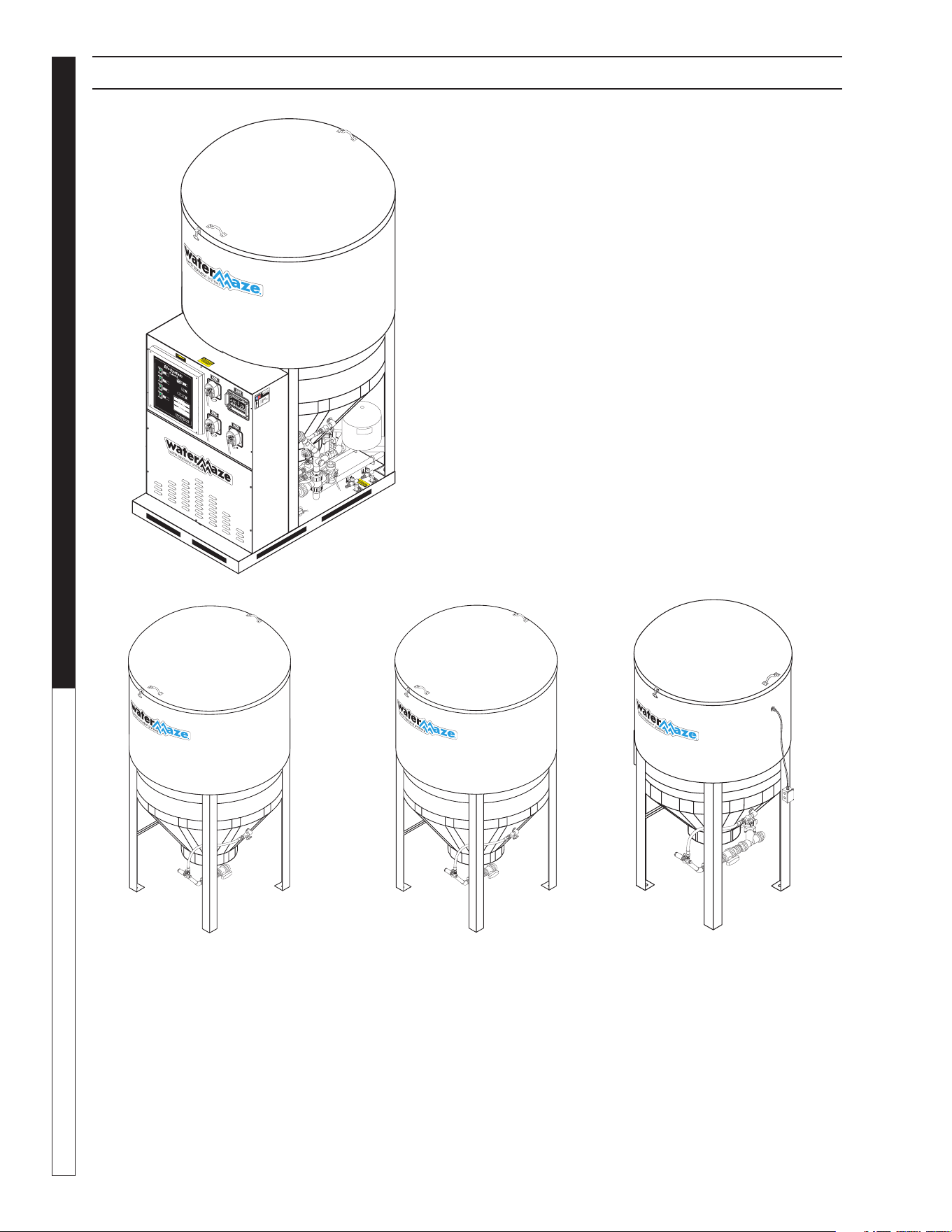
BIO-SYSTEM COMPONENT IDENTIFICATION
CLB-603
Recycle: Main Bio-Digester
Fully automated bio-remediation system includes:
Microbe and nutrient injection system
Infeed pump with circulation system
Ozone generator with circulation pump
Aerator provides dissolved oxygen to water for
microbe health
Auto purge drain system
Optional pH control system
600 gallon unit volume
CLB-30D
Auxiliary Bio-Digester
Auxiliary modular unit con-
nects to main bio-digester (either
CLB-603 or 600) or it can be added to another
tank or system. The CLB-30D, when added
to a main bio-digester, allows you to increase
the total fl ow rate as needed. Unit volume is
600 gallons with process capacity site specifi c.
CLT-600
Auxiliary Tank: 600 Gallons
600 gallon cone-bottom tank is used as a
pre-treatment or post-treatment tank, as
needed. Biology is not injected into this tank,
but it provides added dwell time for biological
processing.
CLT-300
Auxiliary Tank: 300 Gallons
300 gallon cone-bottom tank is used as a pre-
treatment or post-treatment tank, as needed.
Has sockets for a mounting bracket to hold the
optional hydro-screen, when needed.
NOTE: The Water Maze Bio-System is modular
so components can be combined in a variety of
combinations. Your system may not include all of
the components shown below or on next page.
89144580-21
89144580-6
89144580-6
89144580-41
8.914-458.0-G • Water Maze CLB-603
9
WATER TREATMENT SYSTEM
OPERATOR’S MANUAL
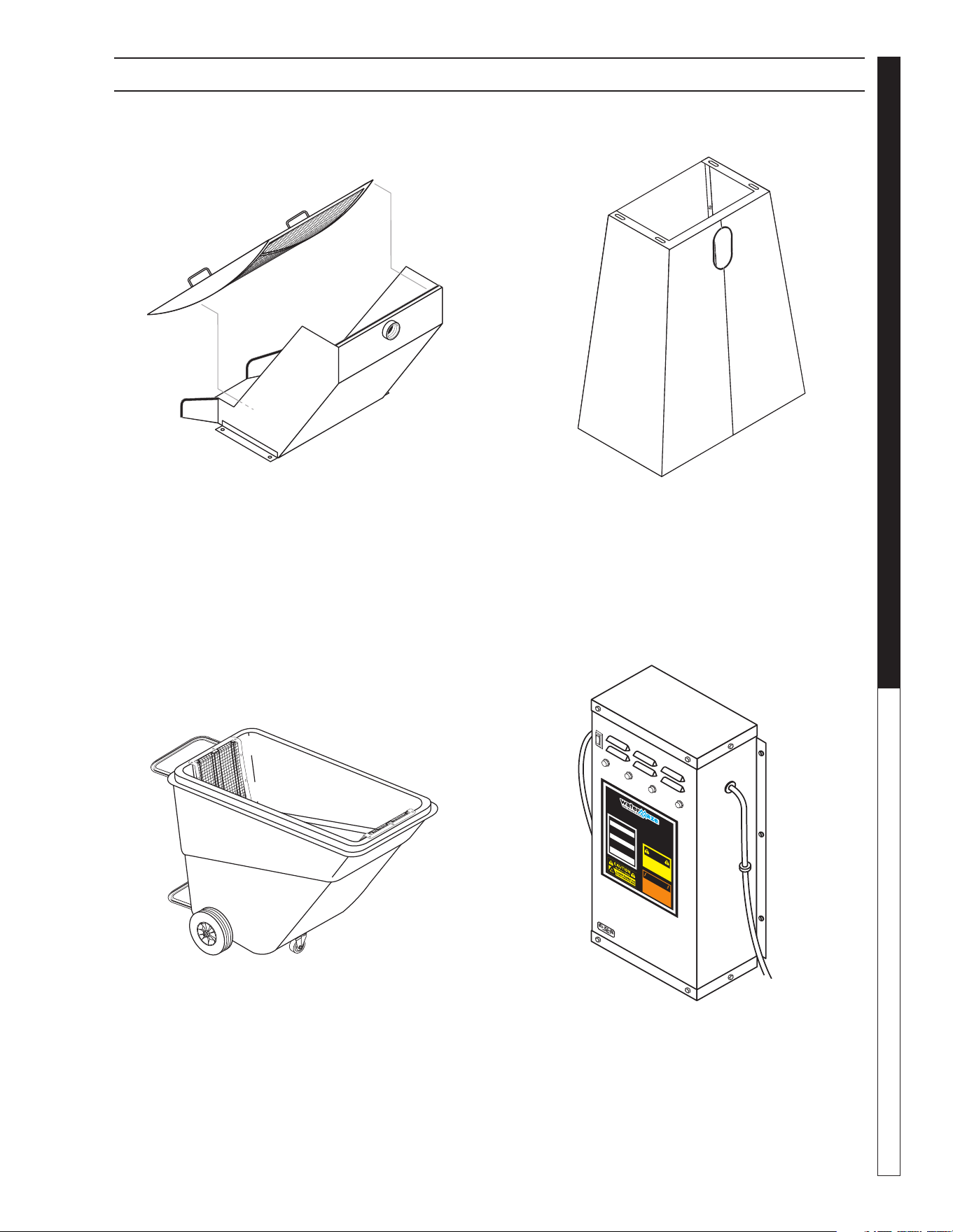
BIO-SYSTEM COMPONENT IDENTIFICATION
Debris Dumpster
Utilized to de-water solids (especially in golf course installations
as containment for grass clippings cascading from Hydro-Screen).
Ozone Generator
The ozone generator produces ozone generated by special UV
lamps, to disinfect water.
89144580-24
OZONE GEN
ERATO
R
D
IS
C
O
N
N
EC
T
F
R
O
M
EL
EC
T
R
IC
A
L
S
U
P
P
L
Y
BEF
O
R
E
SE
R
V
IC
I
N
G
.
D
E
S
C
O
N
E
C
T
E
L
A
C
O
R
R
I
E
N
T
E
E
L
E
C
T
R
I
C
A
A
N
T
E
S
D
E
D
A
R
S
E
R
V
I
C
I
O
.
C
O
U
P
E
R
L
’
A
L
I
M
E
N
T
AT
I
O
N
É
L
E
C
T
R
I
Q
U
E
A
V
A
N
T
D
E
F
A
I
R
E
U
N
E
R
É
P
A
R
A
T
I
O
N
.
D
IS
C
O
N
N
E
C
T
F
R
O
M
E
L
EC
T
R
I
C
A
L
SU
PP
L
Y
BE
F
O
R
E
SER
V
IC
I
N
G
.
D
E
S
C
O
N
E
C
T
E
L
A
C
O
R
R
I
E
N
T
E
E
L
E
C
T
R
I
C
A
A
N
T
E
S
D
E
D
A
R
S
E
R
V
I
C
I
O
.
C
O
U
P
E
R
L
’
A
LI
M
E
N
T
A
T
I
O
N
É
L
E
C
T
R
I
Q
U
E
A
V
A
N
T
D
E
FA
I
R
E
U
N
E
R
É
P
A
R
A
T
I
O
N
.
I
NDI
C
A
TO
R
LI
G
HT
O
P
E
RA
T
I
O
N
A
b
ri
g
h
t
c
o
n
ti
n
uo
u
s
l
i
g
h
t
i
nd
i
c
ate
s
U
V
l
i
g
h
t o
r
b
a
l
l
a
s
t
d
e
fe
c
tiv
e
.
U
n
a l
u
z
l
u
m
i
no
s
a
i
n
d
i
c
a
q
u
e
l
a
l
uz
u
l
tr
a
-
v
i
o
l
e
ta
o
t
r
a
n
s
f
o
r
m
ad
o
r
e
stá
d
e
fe
c
t
uo
s
o
.
U
n
e
l
u
m
i
è
r
e
c
l
a
i
r
e
i
n
d
i
q
u
e
qu
e
l
a
l
u
m
i
è
r
e
u
l
t
r
a
v
i
o
l
e
tt
e
o
u
l
e
t
r
an
s
fo
r
m
a
te
u
r
e
st
d
é
fe
c
tu
eu
x
.
O
PER
AC
IO
N
D
E LA LUZ
IN
D
IC
AD
O
R
A
O
P
ÉR
AT
ION
D
E
LE LAMPE
IN
D
IC
A
T
EU
R
HOT!
C
ALIENTE!
C
HA
U
D
!
CAUTION
P
R
E
C
A
U
C
ION
A
T
T
E
N
T
I
O
N
8
.
90
0
-
4
5
5
.
0
!
WA
R
NING!
A
TE
N
C
I
O
N!
/
A
TT
E
N
TIO
N
!
!
Hydro-Screen
For Screening Leaves, Grass
24" Hydro-Screen effectively screens leaves, grass
clippings and other bio-mass prior to reaching
bio-digester. Includes removable screen for easy cleaning.
Hydro-Screen Stand
Free standing support for Hydro-Screen. Must be bolted to
washpad using concrete anchors.
89144580-27
89144580-28

8.914-458.0-G • Water Maze CLB-603
OPERATOR’S MANUAL WATER TREATMENT SYSTEM
10
INSTALLATION
INSTRUCTIONS
The following instructions will provide adequate information to
fully install your Water Maze Bio-System. Please follow these
instructions step by step to ensure proper installation.
Equipment Need for Installation
Aside from having a general assembly of tools on hand, you will
need to supply a few additional items to complete the installation
of your system:
Gray PVC medium set glue
Purple primer
Tefl on tape
Lubricant (liquid soap)
Pipe fi ttings
Pipe
Installation Instructions
1. Placing the Bio-System
Place the Bio-System on a level concrete pad similar to what
is shown on the Installation Views and the Installation and
Piping Diagrams.
NOTE: Your system may not require all of the components
shown.
2. Placing and Connecting Hydro-screen
(if applicable)
a. Mount hydro-screen on tank or stand as shown in Instal-
lation Drawing.
b. Line up the chute from the hydro-screen so it is above
the sloped end of the debris dumpster.
c. Connect the 1-1/2" hose between hydro-screen and sump
pump connection.
NOTE: The hose may have to be cut to size before it is
connected. The hose should reach both connections and
make a smooth arch without an excess of slack in the line.
3. Place the Debris Dumpster
a. Review Installation Drawing.
b. Place the debris dumpster under the hydro-screen so
that debris falls onto slope section of dumpster (see 2b).
4. Placing the Sump Pump (if applicable)
Review Installation Drawing.
a. Connect PVC tee with gate valve to the 1-1/2" pipe
stubbed out of the sump pump. The elbow of the gate
valve should be facing down toward the bottom of the
catch basin.
b. Place pump securely into corner of catch
basin.
c. Connect plumbing of the sump pump to underground
piping supplied by customer. See Piping Connection
Diagrams.
5. Plumbing the System
Connect equipment with plumbing as shown on the Instal-
lation and Piping diagrams. NOTE: your system may not
require all of the components shown. Plumbing may vary
depending on placement of equipment.
6. Wiring the System
Electrical power is OFF. Before beginning work refer
to Safety Instructions in front portion of manual. Confi rm
that there is not an electrical power source connected to the
control panel. Electrical power will be connected to control
panel later in these instructions.
a. Connect wiring as shown on Electrical Connection
Diagram. NOTE: your system may not have all the
components shown.
7. Connecting Air Supply to the System
a. Connect equipment with air lines as shown on the Air
Connection Diagram.
b. Connect air source to pressure regulators. Air source
must supply 4 CFM at 60-100 psi.
8. Filling the Tanks Dosing the Bio-System
NOTE: Your system may not have all of the components
listed below.
a. CLB-603 (or CLB-600): Fill tank until water begins to
fl ow from 3" overfl ow pipe. Add one 8 oz. bottle set part A
& B of BioStax 1800 and one 8 oz. bottle of BioNutrient.
b. CLT-300: Add enough water to fi ll lower cone section.
No BioStax 1800 or BioNutrient required.
c. CLB-30: Fill tank until water begins to fl ow from 3"
overfl ow pipe. Add one 8 oz. bottle set part A & B of
BioStax 1800 and one 8 oz. bottle of BioNutrient.
d. CLT-600: Fill tank until water begins to fl ow from 3"
overfl ow pipe. Add one 8 oz. bottle set part A & B of
BioStax 1800 and one 8 oz. bottle of BioNutrient.
e. Recycle Holding Tank: Fill tank approxi-
mately half full. No BioStax 1800 or BioNutrient
required.
f. Sump Pit: Pour one 8 oz. bottle set part A & B of Bio-
Stax 1800 and one 8 oz. bottle of BioNutrient into sump
pit.
9. Microbe and Nutrient Injection
a. Mix microbes and nutrient in separate fi ve gallon contain-
ers supplied.
b. Install tubing to pumps and connect to injection probes
located on side of CLB-603 tank. Refer to attached
information for installation and connections.
INSTALLATION INSTRUCTIONS

8.914-458.0-G • Water Maze CLB-603
11
WATER TREATMENT SYSTEM
OPERATOR’S MANUAL
Installation Checklist
Is all piping connected as shown on the Installation and
Piping Diagrams?
Is electrical wiring connected as shown on the Electrical
Connection Diagram?
Are air lines connected as shown on the Air Connection
Diagram?
Is the voltage correct?
Is the fresh water make-up hose connected?
Is the outlet to pressure washer hose connected?
Is the rainwater overfl ow connected?
10. Set Timers
There are four timers in your control panel enclosure that need
to be set. Open control panel door to set timers. Timers are 24
hour and each pin represents half an hour. NOTE: Always
remove electrical power from control panel prior to opening
the door. Rotate each timer until the hour at the center of the
dial meets the actual time of day (a.m. or p.m.). After each
timer is set for the time of day, proceed to instructions below
to set timers to actuate equipment.
a. Infeed Pump Timer: Pull 1 Pin Separated
by 2 Pins (repeat 4 times)
The infeed pump timer provides for water circulation
during system non-use hours to aid in circulation of dis-
solved air and biodigestion by microbes. Circulation of
water must be paused for tank dwell time. Pulling one pin
separated by two pins (and repeated 4 times) will allow for
30 minutes of water circulation separated by one hour of
dwell time. Pulling a pin on this timer will cause the infeed
pump to operate automatically when the hand switch is
on. The circulation pump should be set to
operate during system non-use hours.
b. Ozone Timer: Pull 4 Pins.
The ozone timer controls the amount of time that the
ozone pump and ozone generator operate. Pulling a pin
on this timer will cause the ozone pump and ozone gen-
erator to operate automatically when their hand switches
are on. Ozone water is circulated to the recycle holding
tank to provide disinfected water. The ozone timer
should be set to operate during system
non-use hours.
c. Purge Timer: Pull 1 Pin
The purge timer controls the amount of time that the
tank purge valve operates. The purge valve provides
for sludge removal from the bottom of the cone tank.
Pulling a pin will allow for automatic energizing of the
ten second timer which causes the purge drain valve
to open. Set timer to coordinate with daily
maintenance schedule.
d. Microbe / Nutrient Timer: Pull 3 Pins
This timer determines the amount of microbes and nutrients
that are added to the CLB-603 tank. The microbe /
nutrient timer should be set to inject during
system non-use hours. Pulling a pin on this timer
will cause the Microbe and Nutrient pump to operate au-
tomatically when their hand switches are on.
11. Water Panel Connections:
a. Connect a garden hose from the city water supply to the
"Fresh Water Inlet" connection on the water panel. Refer
to Water Panel Installation Drawing. Make sure hand
valve V5 is open.
b. Connect a garden hose from "Outlet to Pressure Washer"
on water panel to your pressure washer. Make sure hand
valve V7 is open.
INSTALLATION INSTRUCTIONS

8.914-458.0-G • Water Maze CLB-603
OPERATOR’S MANUAL WATER TREATMENT SYSTEM
12
START-UP
1. Make sure that all equipment is level.
2. Turn on the fresh water inlet hose.
3. Fill the sump pit with water and check that the water level
does not drop. This would indicate that the sump pump is
not sealed.
4. Connect Electrical Power to Control Panel: When connecting
to the power supply, follow all electrical and safety codes as
well as the most recent National Electric Code (NEC) and
Occupational Safety and Health Act (OSHA). Ground system
before connecting to the power supply. WARNING: All
wiring must be performed by a qualifi ed elec-
trician.
5. Control Panel Switches:
There are five hand switches located on the
front of the control panel. Turn on all five switches.
Turning on these switches will allow the entire
system to operate in an automatic mode. Normally
switches are left on. The following is the functional
description of these switches.
a. Sump Pump — Hand Switch 1 (HS-1)
The sump pump supplied with this equipment comes
equipped with a level switch for high and low sump water
level control. Turning on this hand switch will allow the
sump pump to operate in an automatic mode. Turning off
the HS-1 switch will not allow this pump to operate.
b. Infeed Pump — Hand Switch 2 (HS-2)
The infeed pump provides two functions:
1. It removes water from a pretreatment tank, a sump or
a CLT-300 and is controlled automatically by Float
Switch 1 (FS-1). In the "ON" position the infeed pump
will turn on at a high level and off at a low level. Turn-
ing off this switch will not allow this pump to operate.
2. It provides circulation in the CLB-603 tank to aid in
bio-digestion by microbes. Circulation fl ow is done
on timer control. Turning off HS-2 will not allow this
pump to provide circulation fl ow to the digester tank.
c. Transfer Pump — Hand Switch 3 (HS-3)
The transfer pump removes water from recycle holding
tank and provides for water fl ow to the water panel. In
the "on" position this pump will operate automatically on
pressure control. Opening the Rinse Water Outlet and
Outlet to Pressure Washer valves that are located on the
water panel will cause this pump to start. Closing these
valves will stop this pump. This pump will not operate if
the HS-3 switch is turned off.
d. Ozone Pump Hand Switch 4 (HS-4)
The ozone pump removes water from the recycle holding
tank, disinfects it and then circulates water back into the
holding tank. This pump along with the ozone genera-
tor operates automatically on timer control. The ozone
generator has a separate on/off switch and this switch
must be in the "on" position for the ozone generator to
operate. Neither the ozone pump nor the ozone generator
will operate if the HS-4 is turned off.
e. Nutrient Pump
Turn "ON" the nutrient pump switch that is located on
the pump housing. The nutrient pump is on timer control
and will not operate if switch is in the "off" position. Feed
adjustment must be at lowest setting. Refer to Metering
Pump Operation.
g. Microbe Pump
Turn "On" the microbe pump switch that is located on
the pump housing. The microbe pump is on timer control
and will not operate if switch is in the "off" position. Feed
adjustment must be at lowest setting. Refer to Metering
Pump Operation.
6. Ozone Generator
Turn on the power switch located on the ozone generator.
The indicator lights on the Ozone Generator will have dim
green lights or no lights if the machine is working and bright
green lights if the ozone generator has malfunctioned.
Setting the Ozone Generator:
An SCFH (Standard Cubic Feet per Hour) gauge is used to
accurately measure the amount of air fl owing through the
ozone delivery line. In other words, the amount of ozone
being injected into the water.
1. With the pump running, disconnect the tubing from the
ozone check valve and connect the tubing to the bottom
fi tting on the gauge. This tube is from the ozone generator.
2. While holding the gauge vertically, connect the tubing
from the ozone injector to the top of the gauge and read
the amount indicated on the gauge. NOTE: You are
measuring suction so make sure the tubing is attached
properly.
3. Begin adjusting the metering valve until 40 SCFH is
achieved.
4. Reconnect the tubing to the ozone check valve.
7. Look over the entire machine for leaks. The machine was
hydrostatically tested at the factory but may have been
damaged in shipment.
START-UP
8.914-458.0-G • Water Maze CLB-603
13
WATER TREATMENT SYSTEM
OPERATOR’S MANUAL
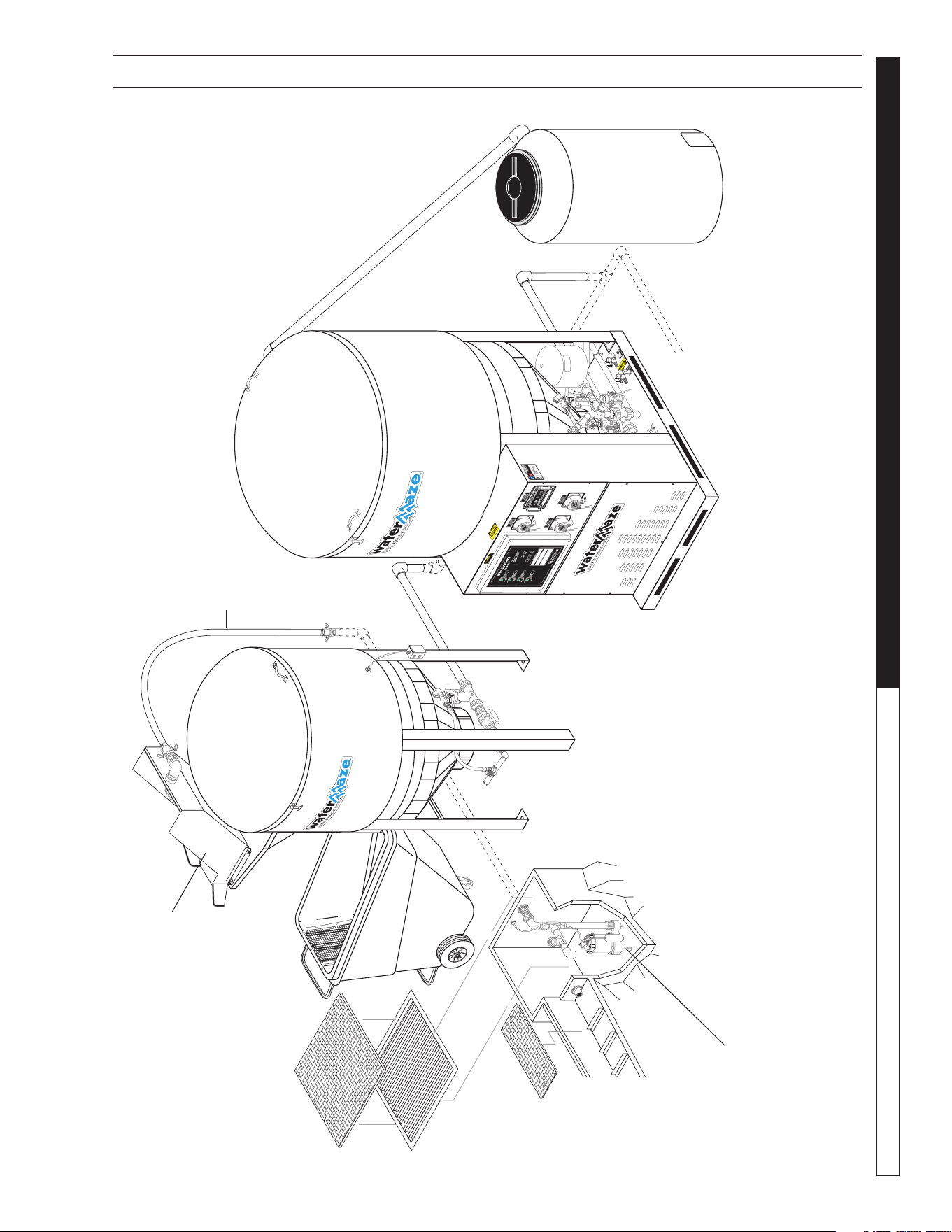
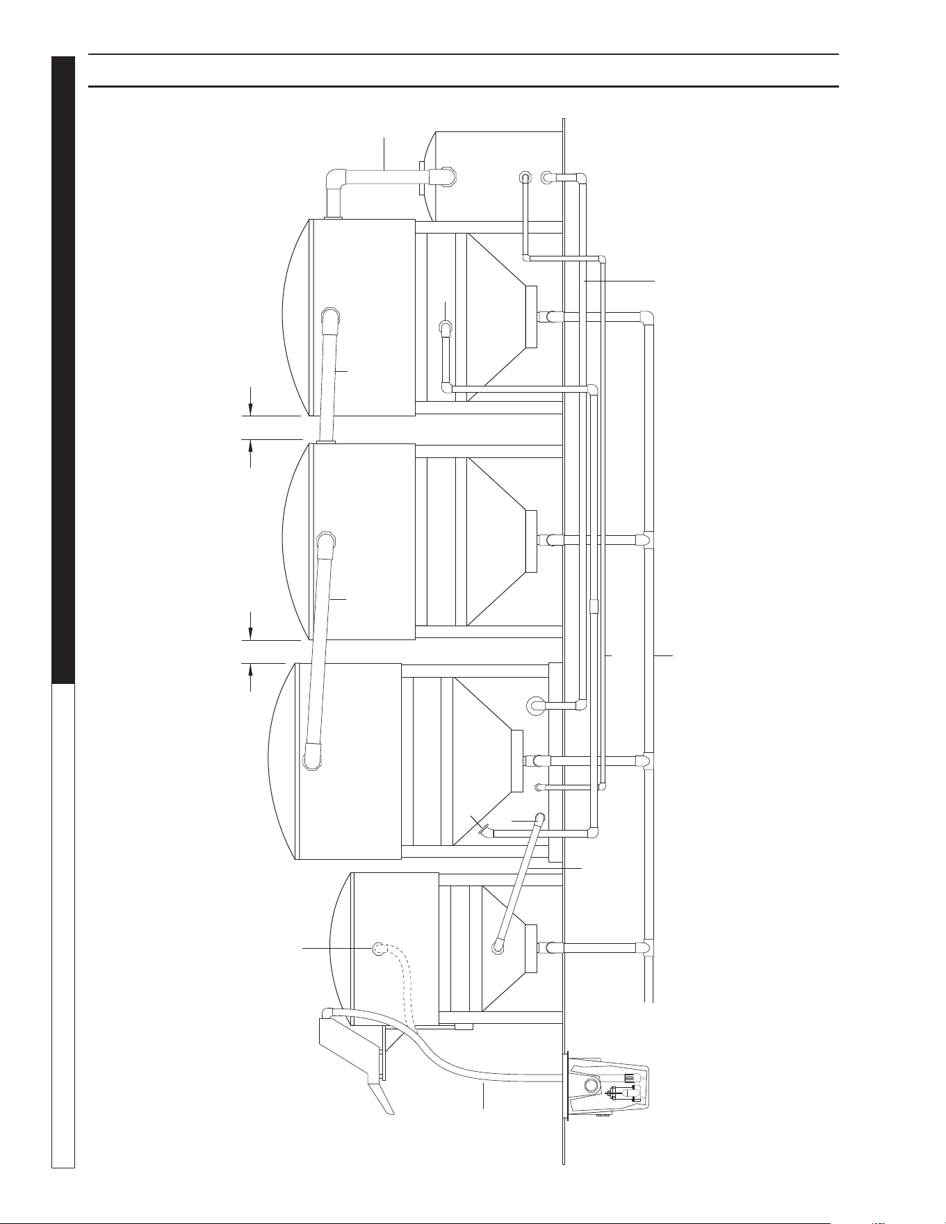
89144580-31
CLB-603 INSTALLATION VIEW WITH OPTIONAL CLT-300
Hydro-Screen
Debris
Dumpster
CLT-300
CLB-603
Sump Pump
Recycle
Holding
Tank
Return Line
Back to
Catch Basin
Trench
Inlet Line
8.914-458.0-G • Water Maze CLB-603
OPERATOR’S MANUAL WATER TREATMENT SYSTEM
14
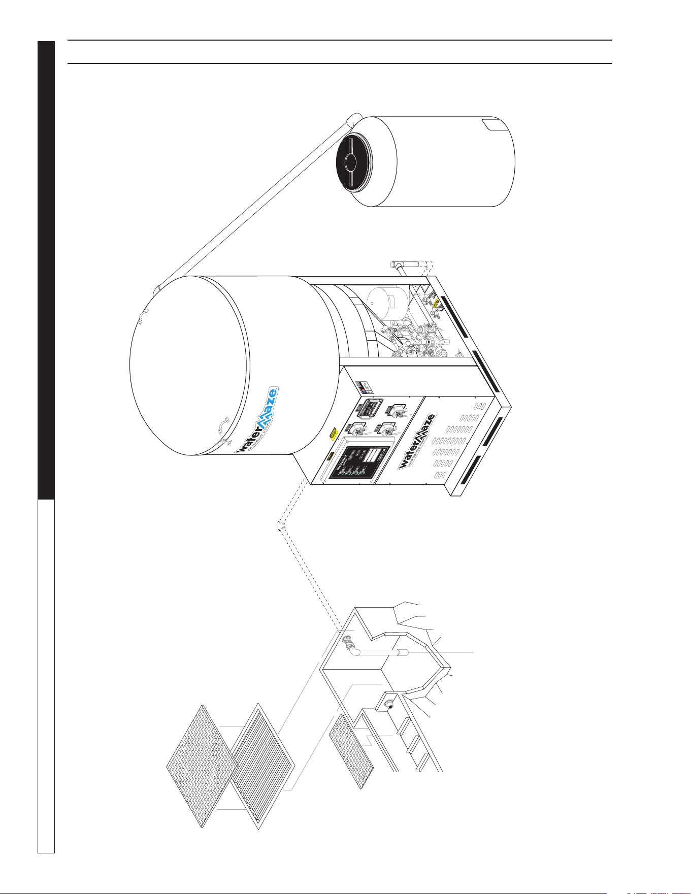
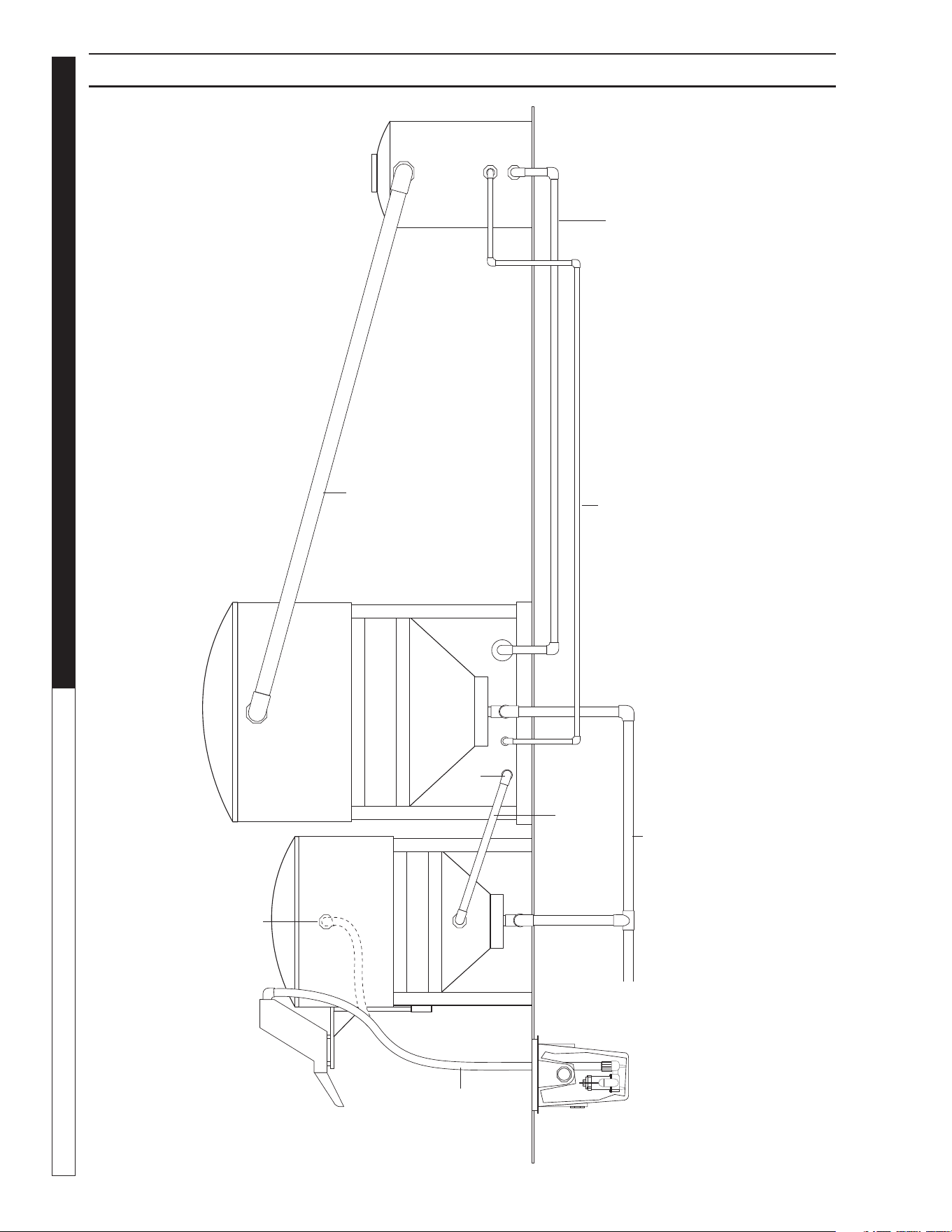
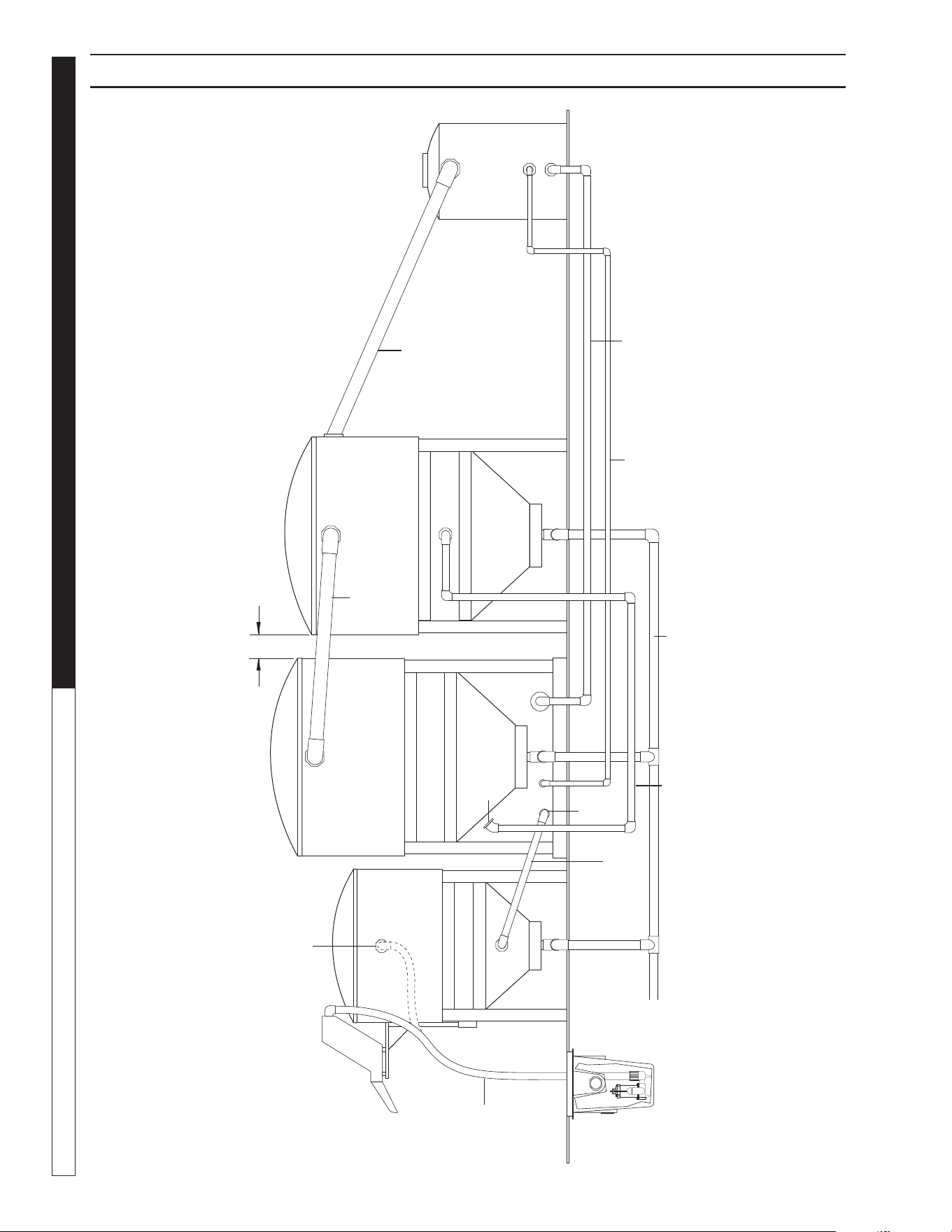
CLB-603 INSTALLATION VIEW
89144580-32
Recycle
Holding
Tank
CLB-603
Foot Valve
Trench
Install Pipe
"T" for
Priming
Infeed Pump
8.914-458.0-G • Water Maze CLB-603
15
WATER TREATMENT SYSTEM
OPERATOR’S MANUAL
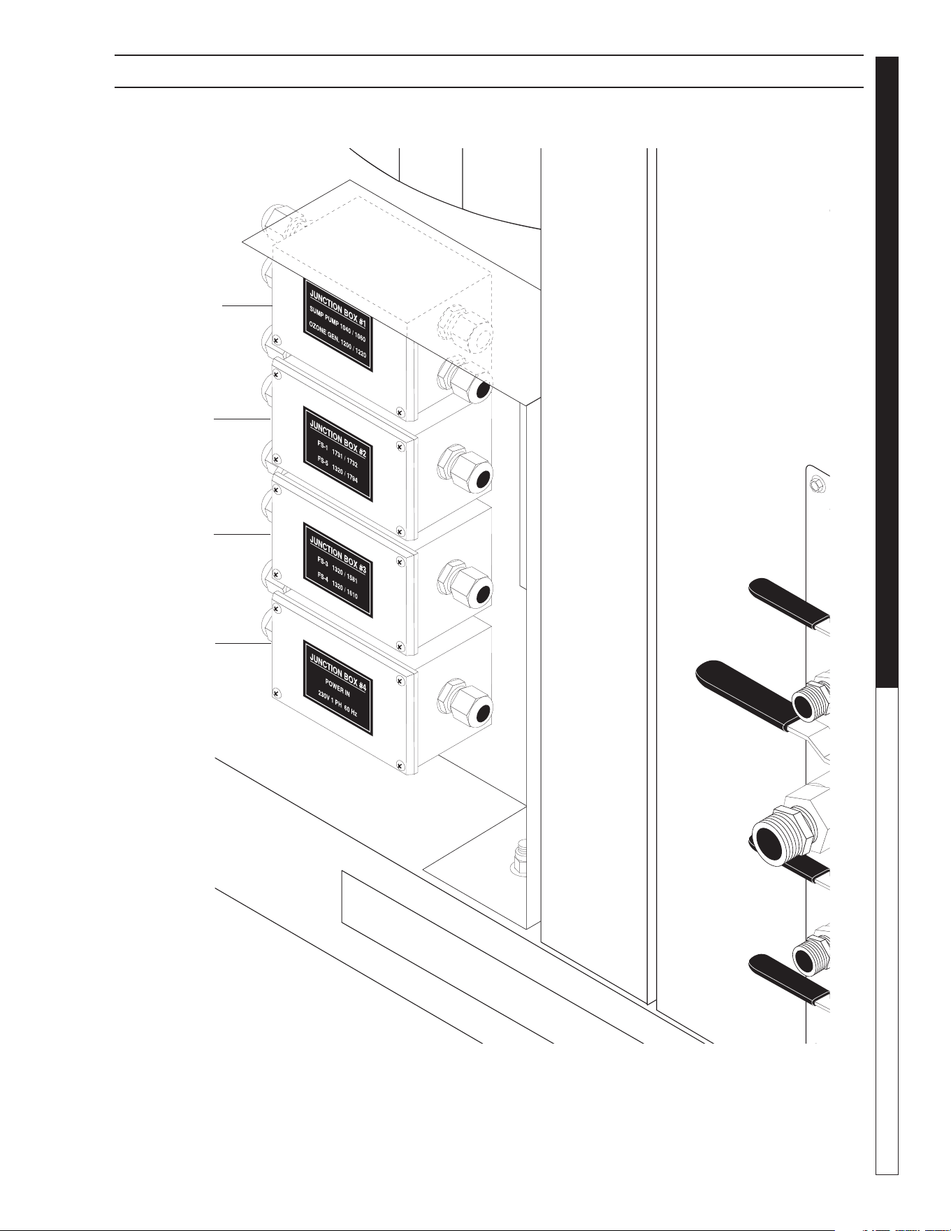
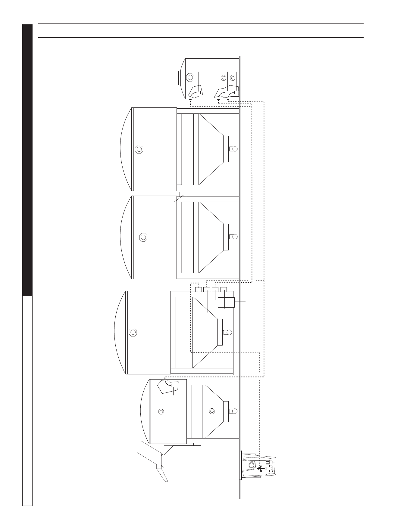
CLB ELECTRICAL INSTALLATION VIEW
89144580-36
Junction Box 1
Junction Box 2
Junction Box 3
Junction Box 4
8.914-458.0-G • Water Maze CLB-603
OPERATOR’S MANUAL WATER TREATMENT SYSTEM
16
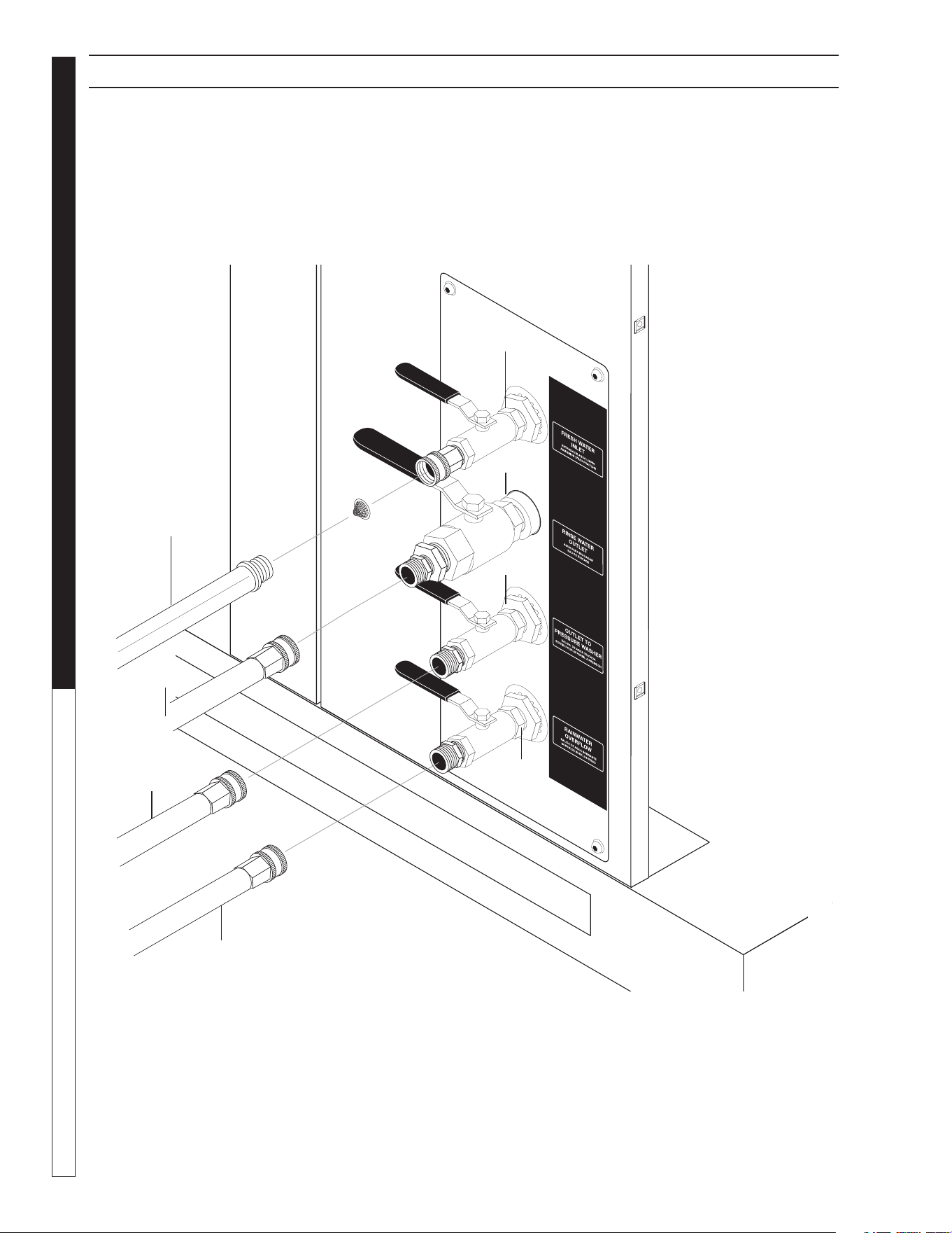
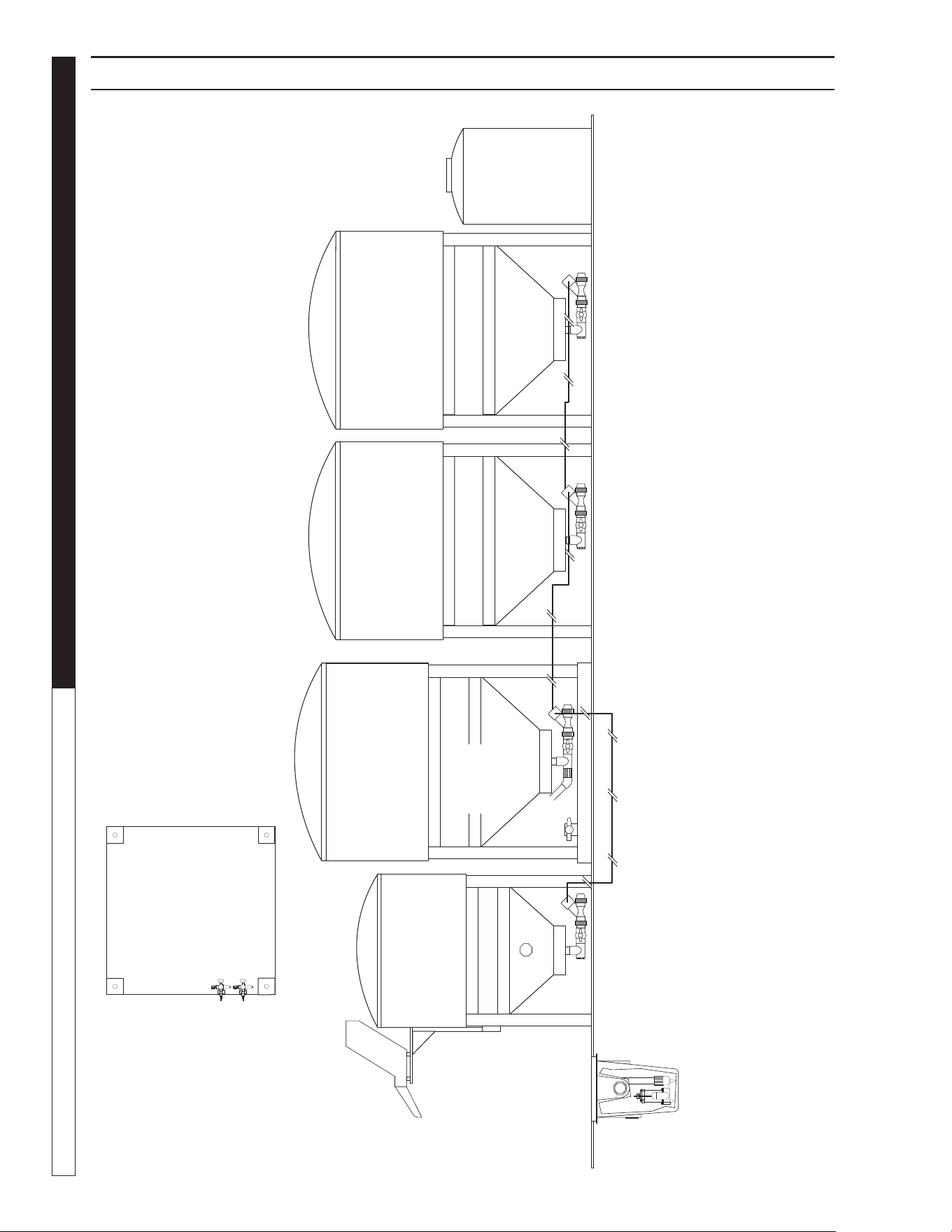
89144580-19
CLB-603 WATER PANEL INSTALLATION VIEW
From Fresh
Water Supply
To Pressure
Washer
To Sewer or
Storage
V5
V8
V6
V7
To Hose Bib
8.914-458.0-G • Water Maze CLB-603
17
WATER TREATMENT SYSTEM
OPERATOR’S MANUAL
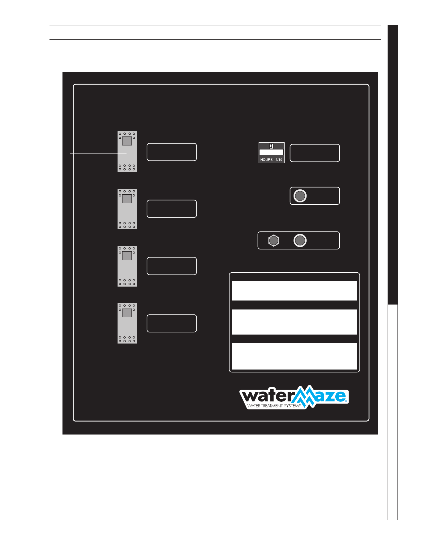
CLB-603 CONTROL PANEL
SUMP PUMP
BOMBA DE CAPTACION
POMPE DE PUISARD
INFEED PUMP
BOMBA DE ALIMENTACION
POMPE A L’AVANCE
BioSystem
OZONE PUMP
BOMBA DE OZONO
POMPE D’OZONE
1
ON
PRENDER
1
ON
PRENDER
1
ON
PRENDER
1
ON
PRENDER
0
OFF
APAGAR
0
OFF
APAGAR
0
OFF
APAGAR
0
OFF
APAGAR
CLB - 603
TRANSFER PUMP
BOMBA DE TRANSFERENCIA
POMPE DE TRANSFERT
RUNNING HOURS
HORAS DE OPERACION
HEURES D’OPÉRATION
PURGE
PURGAR
PURGER
VOLTAGE
VOLTAJE
OPERATING IN STRUC TIONS
INSTRUCCIONES DE OPERACION
INSTRUCTIONS D’OPÉRATION
BEFORE STARTING: Inspect all water and electrical
lines for proper connections. Read operator’s manual for
proper maintenance procedures and safety in struc tions.
START UP: Turn all pump switches on. Pumps will
automatically start when water reaches proper level.
ANTES DE PARTIR: Revise todas las lineas de agua
y electricas para asegurar su correcta conexión. Lea el
manual de operación para observar las instrucciones de
mantenimiento y seguridad.
PARA PARTIR: Ponga todos los interruptores de las
bombas a la posición ON. Las bombas partirán automáti-
camente cuando el agua alcance el nivel adecuado.
AVANT LA MISE EN MARCHE: Vérifi er toutes les
conduites d’eau et d’électricité pour vous assurer
que tous les raccords sont étanches. Lire le manuel
de l’opérateur pour les in struc tions d’opération et
d’entretien.
MISE EN MARCHE: Mettre tous les interrupteurs
de pompe en position ON. Les pompes se mettront
automatiquement en marche lorsque le niveau d’eau
atteindrait la hauteur appropriée.
ARRÊT: Tourner tous les interrupteurs en posi-
tion OFF.
ENTRETIEN: Vous révérer au manuel de
l’opérateur pour les procédures d’entretien.
PARA DETENER LA MA QUINA: Ponga todos
los interruptores a la posición OFF.
MANTENIMIENTO: Lea el manual de oper-
ación para conocer el completo procedimiento
de mantención.
SHUT DOWN: Turn switches off.
MAINTENANCE: Refer to operator’s manu-
al for complete maintenance procedures.
11-4009
0 0 0 0 0 0
89144580-45
HS1
HS2
HS3
HS4
8.914-458.0-G • Water Maze CLB-603
OPERATOR’S MANUAL WATER TREATMENT SYSTEM
18
89144580-14
PIPING CONNECTION DIAGRAM #1
Notes:
1. Connect G2 to G3 When Hydro-screen Option is Not Supplied
Rear View of Equipment
Hydro-Screen
G1
1-1/2"
Flex Hose
Sump
Pump
To Drain
2" Line
(3" if Underground)
Note 2
D2
A2
CLT-300
G3
(Alternate
Connection
Note 1)
E1
CLB-603A
A1
B1
D1
C1
3" Line
Slope 1"/Ft
Minimum
E2
Recycle
Holding Tank
B2
C2
1-1/2" Line
(2" if Underground)
1" Line
(2" if Underground)
1-1/2"
Line
G2

8.914-458.0-G • Water Maze CLB-603
19
WATER TREATMENT SYSTEM
OPERATOR’S MANUAL
CONNECTION SIZE TYPE MATERIAL DESCRIPTION ACTION
A1 1.5" SLIP PVC Infeed Pump Inlet
Connect A1 to A2
A2 1.5" NPT Polypropylene Feed Tank Outlet
B1 1" SLIP PVC Ozone Pump Outlet
Connect B1 to B2
B2 1" NPT Polypropylene Recycle Holding Tank Outlet
C1 1.5" SLIP PVC Transfer/Ozone Pump inlet
Connect C1 to C2
C2 1.5" NPT Polypropylene Recycle Holding Tank Outlet
D1 2" SLIP PVC Tank Bottom Drain
Connect D1, D2 to Drain
Manifold
D2 2" SLIP PVC Tank Bottom Drain
E1 3" NPT Polypropylene Gravity Flow Outlet
Connect E1 to E2
E2 3" NPT Polypropylene Gravity Flow Inlet
G1 1.5" NPT Flex Hose Hydro-Screen Inlet
Connect G1 to G2
G2 1.5" NPT Iron Sump Pump Outlet
PIPING CONNECTION TABLE DIAGRAM #1
8.914-458.0-G • Water Maze CLB-603
OPERATOR’S MANUAL WATER TREATMENT SYSTEM
20
89144580-15
PIPING CONNECTION DIAGRAM #2
Notes:
1. Connect G2 to G3 When Hydro-Screen Option is Not Supplied
Rear View of Equipment
Hydro-Screen
G1
G3 (Alternate
Connection
Note 1)
CLT-300
CLB-603A
CLB-30 CLT-600
24" Maximum Spacing
24" Maximum Spacing
E1
3" Line
E2
E3
3" Line
E4
E5
3"
line
E6
Recycle
Holding
Tank
B2
C2
Note 2
C1
1-1/2" Line
(2" if
Underground)
1" Line
(2" if Underground)
2" Line
(3" if Underground)
D1B1
A1
1-1/2"
Line
D2
Note 2
A2
G2
1-1/2"
Flex Hose
Sump
Pump
To Drain
H1
H2

8.914-458.0-G • Water Maze CLB-603
21
WATER TREATMENT SYSTEM
OPERATOR’S MANUAL
PIPING CONNECTION TABLE DIAGRAM #2
CONNECTION SIZE TYPE MATERIAL DESCRIPTION ACTION
A1 1.5" SLIP PVC Infeed Pump Inlet Connect A1 to A2
A2 1.5" NPT Polypropylene Feed Tank Supply Connect A1 to A2
B1 1" SLIP PVC Ozone Pump Outlet Connect B1 to B2
B2 1" NPT Polypropylene Ozone Pump Inlet Connect B1 to B2
C1 1.5" SLIP PVC Transfer/Ozone Pump Inlet Connect C1 to C2
C2 1.5" NPT Polypropylene Holding Tank Outlet Connect C1 to C2
D1 2" SLIP PVC Tank Bottom Drain
Connect D1, D2, D3 to
Drain Manifold
D2 2" SLIP PVC Tank Bottom Drain
D3 2" SLIP PVC Tank Bottom Drain (optional)
D4 2" SLIP PVC Tank Bottom Drain (optional)
E1 3" NPT Polypropylene Gravity Flow Outlet Connect E1 to E2
E2 3" NPT Polypropylene Gravity Flow Inlet Connect E1 to E2
E3 3" NPT Polypropylene Gravity Flow Outlet Connect E3 to E4
E4 3" NPT Polypropylene Gravity Flow Inlet Connect E3 to E4
E5 3" NPT Polypropylene Gravity Flow Inlet Connect E3 to E4
E6 3" NPT Polypropylene Gravity Flow Inlet Connect E3 to E4
G1 1.5" NPT Flex Hose Hydro-screen Inlet Connect G1 to G2
G2 1.5" NPT Iron Sump Pump Outlet Connect G1 to G2
H1 1.5" NPT PVC Circulation Inlet
(close gate valve)
Connect H1 to H2
H2 1.5" NPT Polypropylene Outlet from Tank Connect H1 to H2
8.914-458.0-G • Water Maze CLB-603
OPERATOR’S MANUAL WATER TREATMENT SYSTEM
22
PIPING CONNECTION DIAGRAM #3
NOTES:
1. Connect G2 to G3 When Hydro-Screen Option is Not Supplied
Rear View of Equipment
89144580-16
Hydro-Screen
G1
G3
(Alternate
Connection
Note 1)
CLT-300
CLB-603A
CLT-600
A2
1-1/2"
Flex Hose
Sump
Pump
To
Drain
Note 2
D2
1-1/2"
Line
A1
1-1/2" Line
(2" if Underground)
1" Line
(1-1/2" if
Underground)
2" Line
(3" if Underground)
E1
H1
B1
D1
C1
Note 2
D3
3" Line
E2
E3
3"
Line
Slope 1"/ft.
Minimum
1-1/2" Line
(2" if Underground)
B2
C2
E4
Recycle
Holding
Tank
24" Maximum Spacing
G2
H2

8.914-458.0-G • Water Maze CLB-603
23
WATER TREATMENT SYSTEM
OPERATOR’S MANUAL
PIPING CONNECTION TABLE DIAGRAM #3
CONNECTION SIZE TYPE MATERIAL DESCRIPTION ACTION
A1 1.5" SLIP PVC Infeed Pump Inlet Connect A1 to A2
A2 1.5" NPT Polypropylene Feed Tank Outlet Connect A1 to A2
B1 1" SLIP PVC Ozone Pump Outlet Connect B1 to B2
B2 1" NPT Polypropylene Ozone Pump Inlet Connect B1 to B2
C1 1.5" SLIP PVC Transfer/Ozone Pump Inlet Connect C1 to C2
C2 1.5" NPT Polypropylene Holding Tank Outlet Connect C1 to C2
D1 2" SLIP PVC Tank Bottom Drain
Connect D1, D2, D3 to
Drain Manifold
D2 2" SLIP PVC Tank Bottom Drain
D3 2" SLIP PVC Tank Bottom Drain (optional)
E1 3" NPT Polypropylene Gravity Flow Outlet Connect E1 to E2
E2 3" NPT Polypropylene Gravity Flow Inlet Connect E1 to E2
E3 3" NPT Polypropylene Gravity Flow Outlet Connect E3 to E4
E4 3" NPT Polypropylene Gravity Flow Inlet Connect E3 to E4
G1 1.5" NPT Flex Hose Hydro-Screen Inlet Connect G1 to G2
G2 1.5" NPT Iron Sump Pump Outlet Connect G1 to G2
H1 1.5" NPT CPVC Circulation Inlet (close gate valve) Connect H1 to H2
H2 1.5" NPT Polypropylene Circulation Outlet Connect H1 to H2
8.914-458.0-G • Water Maze CLB-603
OPERATOR’S MANUAL WATER TREATMENT SYSTEM
24
ELECTRICAL FIELD CONNECTION CLB-603A
Rear View of Equipment
89144580-9
CLT-600
CLB-30
CLB-603A
CLT-300
FS1
JB1
JB2
JB5
JB4
JB3
Ozone
Generator
FS3
Recycle
Holding
Tank
FS4
FS5
Sump Pump

8.914-458.0-G • Water Maze CLB-603
25
WATER TREATMENT SYSTEM
OPERATOR’S MANUAL
JUNCTION BOX WIRE NUMBER CONNECT TO FUNCTION
JB1 1040 Sump Pump Sump Pump 1/60/230 Volt
1060
JB1 1200 Ozone Generator Ozone Generator 1/60/230 Volt
1220
JB2 1731 FS1 Infeed Pump Control, NO (Black Float Switch)
1732
JB2 1320 FS5 Transfer Pump Permissive, NO
1794 (Black Float Switch)
JB3 1320 FS3 Rain Water Overfl ow Solenoid, NO
1581 (Black Float Switch)
JB3 1320 FS4 Fresh Water Makeup Solenoid NC
1610 (Gray Float Switch)
JB4 102L1 Power Source Electrical Power to CLB603
102L2 1/60/230 Volt, 15A
NOTE: Installations may not include all of the above components
ELECTRICAL FIELD CONNECTION TABLE CLB-603A
8.914-458.0-G • Water Maze CLB-603
OPERATOR’S MANUAL WATER TREATMENT SYSTEM
26
89144580-7
AIR CONNECTION DIAGRAM
CLT-300
CLB-603A
CLB-30 CLT-600
V2
R1 &
R2
V1
V3
V4
Recycle
Holding
Tank
NOTE:
The Model CLB-603A is equipped with an air pilot actuator mounted on the purge valve designated as V1 (shown above)
Valves V2, V3 and V4 must be connected to V1 as shown.
Note: Automatic purge valves V2, V3 and V4 are optional and may not have been supplied.
Rear View of Equipment
Air
Pressure
Regulator
R1
R2
R1: Pressure Regulator for Purge Drain Valves. Customer to Supply: 3 SCFM @ 60-100 PSI Air Pressure
R2: Pressure Regulator for Air Stone Diff user. Customer to Supply: 1 CFM @ 60-100 PSI Air Pressure.
Plan View of
CLB-603A
Baseplate
8.914-458.0-G • Water Maze CLB-603
27
WATER TREATMENT SYSTEM
OPERATOR’S MANUAL
89144580-34
RECYCLE HOLDING TANK INSTALLATION
Alternate 3"
Connection
See
Note
#1
12"
12"
12"
12"
6"
FS3:
Rain Water Overfl ow
Black Float
(NO Contacts)
FS4
Fresh Water
Makeup Grey
Float
(NC Contacts)
FS5:
Permissive to
Start Transfer
Pump Black Float
(NO Contacts)
NOTE #1:
Locate 3" bulkhead at highest point on recycle holding tank while maintaining a 1"/ft. slope on
inlet pipe from Bio-System
3" Connection
1"
Connection
1-1/2"
Connection
8.914-458.0-G • Water Maze CLB-603
OPERATOR’S MANUAL WATER TREATMENT SYSTEM
28
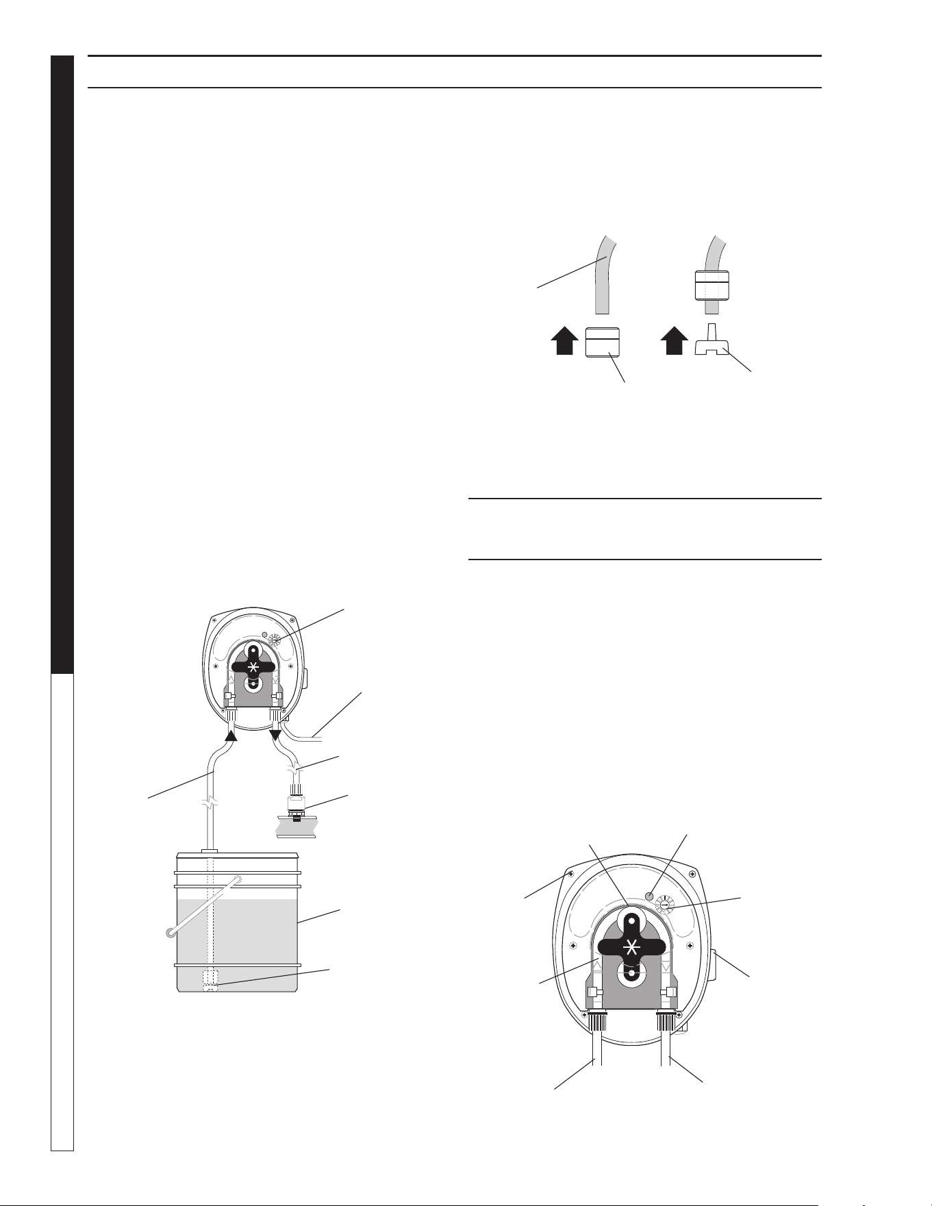
Variable Speed Peristaltic Pump
TECHNICAL INFORMATION
Materials:
Squeeze Tubing Special synthetic rub ber
Strainer and
Injection Point Fitting PVC
Feed Rate: 1-7 or 8-45 GPD
Tubing Size: 1-7 or 8-45 GPD
Dimensions: Height = 5"
Width = 4"
Depth = 4 1/4"
Standard Accessories Provided with Pump:
• Squeeze Tubing
• Check Valve Assembly
• Strainer with Weight
• Bulkhead Fitting with Elbow
Electrical Rating:
• 20-265 VAC
• 7 W
• 50/60 Hz
Maximum System Pressure: 45 PSI
Installation
1. Suction Tubing: Take the 5 ft. length of 1/4" O.D. tubing
in clud ed, measure and cut the lengths needed to run from
pump head to the chemical tank. Cut the tubing ends square.
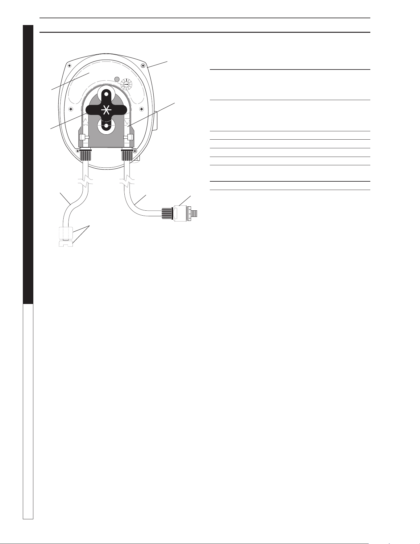
Indicator Light
Cover
Screws
Pump Rollers
2. Connect Suction Tubing To Pump: Remove com-
pression fi tting. Feed tube through fi tting. Push end of the
tube on fi tting. Tighten fi tting fi rmly.
NOTE: To soften the end of the tubing, im merse it in hot
water.
3. Connect Suction Tubing To Strainer: In stall
strainer so it’s off the bottom of the chemical con tain er. Cut
the suction tub ing to the length need ed. Put weight on tubing.
Push strainer end into tubing.
METERING PUMP
OPERATION
If not already done, put the end of the suction tub ing into the
chemical container, near the bottom.
Move the “ON-OFF” switch to ON.
Prime: To prime the pump and lines push the 3-way switch to
full speed.
Feed Adjustment: (ONLY A QUALIFIED WATER MAZE
SERVICE TECH NI CIAN SHOULD MAKE THIS AD JUST MENT.)
The feed adjustment is under the cover plate. Remove the plate
and turn the adjusting screws clockwise to in crease feed or coun-
terclockwise to decrease feed.
METERING PUMPS
Chemical
Container
Suction
Tube
Discharge
Tube
Check Valve
Speed
Adjustment
Power
Cord
Strainer
Inlet
Squeeze
Tube
Speed
Adjusting
Screw with
Indexing
Mark
On-Off -Full
Speed Switch
(right or left
side)
Discharge
1 2
Strainer
End
Weight
Suction
Tube
8.914-458.0-G • Water Maze CLB-603
29
WATER TREATMENT SYSTEM
OPERATOR’S MANUAL
DANGER: DO NOT ATTEMPT TO FEED CHEMI-
CALS WITHOUT CONSULTING YOUR CHEMICAL
FEEDER DEALER OR CHEMICAL SUPPLIER.
DANGER: NE PAS TENTER D'ALIMENTER DES
PRODUITS CHIMIQUES SANS D'ABORD CON-
SULTER LE CONCESSIONNAIRE D'ALIMENTATION
EN PRODUITS CHIMIQUES OU LE FOURNISSEUR
DE PRODUITS CHIMIQUES.
CAUTION: Wear protective
gloves, goggles, and other
adequate protection for the
chemical hazard.
ATTENTION: Porter des gants
de protection, des lunettes
étanches et d'autres protec-
tions adéquates pour les ris-
ques chimiques.
Before replacing the pump head, remove chemical from tubing
as follows:
1. Remove strainer from chemical tank.
2. Run pump until all chemical is removed from the tubing.
FILLING THE CHEMICAL TANK: To avoid running out, of
chemical, follow a regular schedule of monitoring chemical supply.
Also inspect and clean the strainer by fl ushing with a compatible
liquid, as needed.
TUBING INSPECTION: Inspect all tubing regularly and
replace it if it is deteriorating.
REPLACING PUMP HEAD TUBING:
1. Remove compression fi ttings from the tubing at the pump
head.
2. Pull the suction and discharge tubing from the pump head.
3. Remove the front cover of the pump.
4. Rotate the pump rollers to a vertical position.
5. Lift the inlet fi tting out of the housing.
6. Pull tube out while rotating the rollers clockwise.
7. Remove the outlet fi tting.
8. Install the inlet fi tting for the new tube assembly.
CAUTION: DO NOT LOSE THE BEARING FROM
THE CENTER HOLE IN THE BACK COVER.
ATTENTION: NE PAS DESSERRER LE PALIER
DE TROU CENTRAL DANS LA PLAQUE DU
COUVERCLE.
9. Press the tube into place in front of a roller while rotating the
roller assembly clockwise.
10. Install the outlet fi tting.
11. Reconnect the suction and discharge lines.
12. Install front cover.
CAUTION: Clear or transparent plastic tubing
should be replaced at least every three months
if exposed to the sun. Replace tubing yearly if
feeder is installed indoors.
ATTENTION: Un tube en plastique clair ou
transparent devrait être remplacé au moins
tous les trois mois s'il est exposé au soleil.
Remplacer le tube une fois par année si le dis-
positif d'alimentation est installé à l'intérieur.
INSPECT FOR LEAKAGE: Inspect the chemical system
daily for any signs of leakage. If leaking occurs at tubing con-
nections, tighten fi tting compression nut fi nger tight. If leakage
continues, remove pressure from the system. Disconnect the
tubing, trim ends square and reconnect.
INSPECT FOR BLOCKED FLOW: Precipitates or other
chemical reactions cause injection points to clog. If the type of
chemical being fed eliminates the use of fl ushing solution, the
injection point must be inspected at regular intervals. Strainers
must be kept clean with periodic back-fl ushing.
WARNING
PROTECTIVE
EYEWEAR AND
CLOTHING MUST
BE WORN.
METERING PUMP MAINTENANCE
8.914-458.0-G • Water Maze CLB-603
OPERATOR’S MANUAL WATER TREATMENT SYSTEM
30
METERING PUMP AND PARTS LIST
ITEM PART NO. DESCRIPTION QTY
1 8.749-855.0 Pump, Peristaltic, PR-7,
8-45 gpd 1
8.749-856.0 Pump, Peristaltic, PRS-1,
1-7 gpd
2 8.749-862.0 Tube, Squeeze, Santoprene,
PR-7,
* 8-45 gpd 1
8.749-864.0 Tube, Squeeze, Santoprene,
PRS-1,
* 1-7 gpd
3 8.749-860.0 Check Valve, PVC 1
4 8.749-857.0 Tubing, 1/4", PE, Black AR
5 8.749-863.0 Strainer, w/Welght 1
6 8.711-737.0 Tubing, 1/8", ID, Norprene AR
7 8.751-801.0 Faceplate, PRS-1/ PR-7 1
8 8.751-375.0 Roller Assembly, P 1
8-751-376.0 Roller Assembly, PRS-1 1
* Alternative tubing materials are available
1
2
3
6
8
7
4
5
8.914-458.0-G • Water Maze CLB-603
31
WATER TREATMENT SYSTEM
OPERATOR’S MANUAL
WARNING: Live electrical con-
tacts are exposed, so discon-
nect power fi rst and have work
performed by a qualifi ed elec-
trician.
AVERTISSEMENT: Les contacts
électriques sous tension sont
exposés, il faut donc d'abord
débrancher l'alimentation élec-
trique et confi er le travail à un électricien qualifi é.
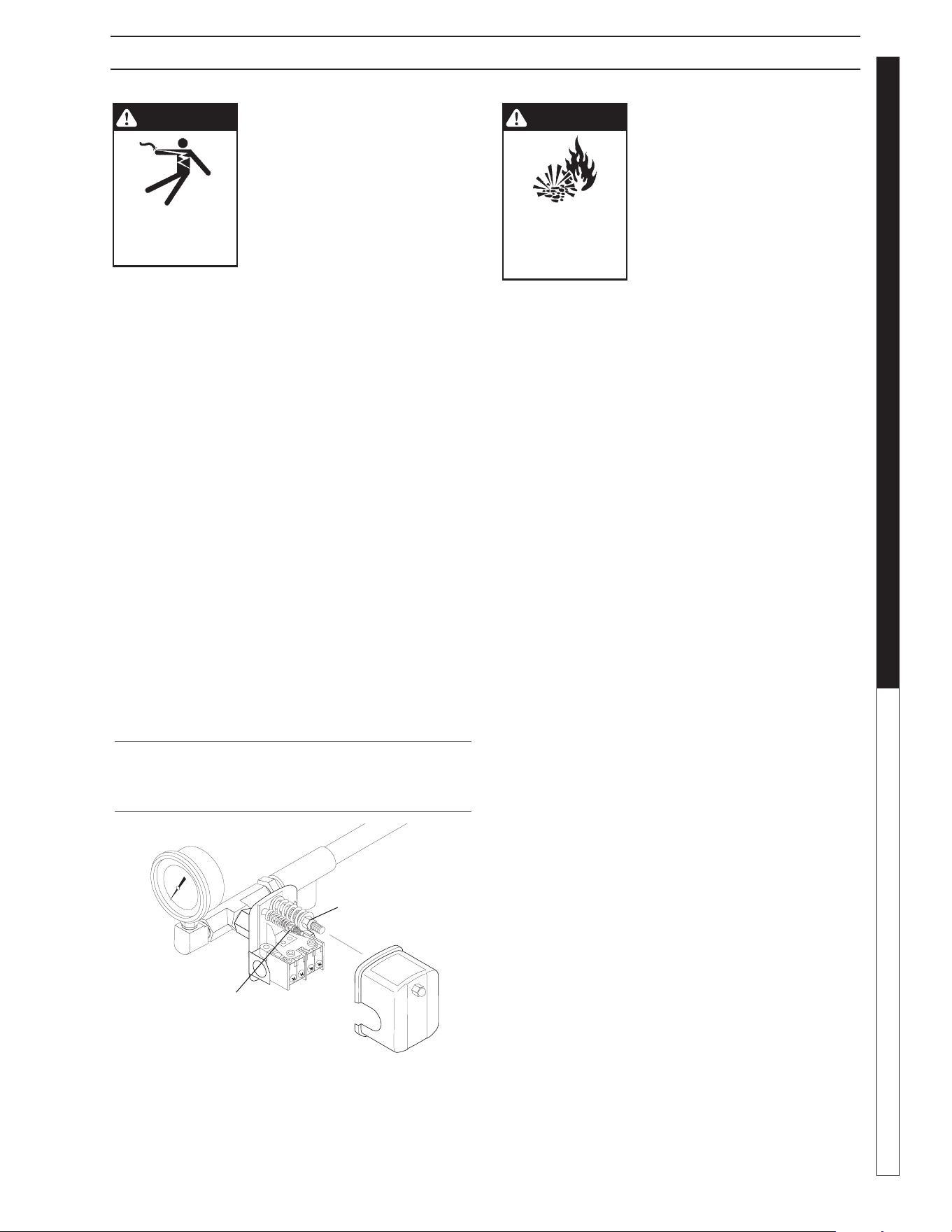
Remove cover of the pump pressure control switch to allow ac-
cess to the two nuts used to adjust the pump operating pressure.
The pressure switch on Water Maze equipment is set at the factory
and should not have to be adjusted at start-up, but will need to
be verifi ed at start up and maintained regularly at least monthly.
1. The nut on the larger spring in the pump pressure switch,
adjusts the pump cut in (cut on) and pump cut out (cut off)
pressures simultaneously.
2. The nut atop the smaller spring in the pump pressure switch
only controls the cut out range and is used to narrow or widen
the gap between the pump cut in and cut out pressures.
3. To cycle the pump less frequently, the gap should be as wide
as possible while still allowing the pump to shut off quickly
when all outlets are closed. Adjust the smaller spring to widen
the gap between pump in and out (on and off). 40-45 PSI
(CLP, Rec2-20) or 30 PSI (EC1-300A) is desirable. Adjusting
the larger spring should not be necessary.
4. When making pressure switch adjustments, make sure all
pump outlets are off or closed, except for the one outlet valve
used to relieve and build pressure while making pressure
switch adjustments.
PRESSURE TANK
OPERATION
WARNING! When the tank has
been in service and a change
to a higher pre-charge pressure
is necessary because of a re-
quired change in the pressure
switch setting, failure to follow
instructions below can cause a
rupture or explosion and could
cause serious or fatal personal
injury and/or property damage.
AVERTISSEMENT: Après avoir eff ectué
l'entretien du réservoir, il est nécessaire de
passer à une pression de précharge supérieure
en raison d'un changement requis du paramètre
du pressostat; le non-respect des directives
ci-dessous peut causer une rupture ou une
explosion, et pourrait causer des lésions corpo-
relles graves ou fatales et/ou des dommages à
la propriété.
• Do not adjust or add pressure if there has been a loss of air.
• Do not adjust the pre-charge pressure if there is visible
exterior corrosion.
• Do not adjust the pre-charge pressure if there has been a
reduction of the pump cycle time or the pre-charge pres-
sure compared to its initial setting. A reduction in pump
cycle time can result from loss of tank corrosion and any
re-pressurization or additional pressure could result in rupture
or explosion.
• Pressure tank pressure is factory set but will have to be
checked regularly (at least monthly). Use an air pressure
(tire) gauge. Before checking air pressure on the pressure
tank, purge all water out of the tank by turning the pump on
and pumping all water out of the pressure tank.
1. Our transfer pump water systems use a water pressure tank
and water pump with these two pressure operation ranges:
Cut in (start pumping): 20 PSI
Cut out (stop pumping): 30 PSI (EC1-300A)
Cut out (stop pumping): 40-45 PSI (CLP, REC2-20)
2. Typical factory set air pressure on bladder-type residential
water pressure tanks are shipped from the factory with a
standard pre-charge of:
18 psig for models WX-101 and WX-102
18 psig for models WX-103 and WX-203
18 psig for models WX-205 and WX-350
3. Set the well tank air pressure to 2 PSI below the pump pres-
sure switch cut-in pressure. This is usually 18 PSI.
WARNING
RISK OF
EXPLOSION:
FOLLOW
INSTRUCTIONS
WHEN CHANGING
PRESSURE
WARNING
RISK OF
ELECTRIC SHOCK:
USE CAUTION
WHEN HANDLING.
PRESSURE SWITCH AND PRESSURE TANK OPERATION
89174360-14
Controls
Cut In/Cut Out
Controls
Cut Out Range
8.914-458.0-G • Water Maze CLB-603
OPERATOR’S MANUAL WATER TREATMENT SYSTEM
32
ATTENTION: Ne jamais regarder la lampe d'ozone
non protégée pendant l'utilisation de la machine.
Cette lampe peut causer de graves dommages
aux yeux et à la peau. Le voyant lumineux sera
vert (faible) ou éteint lorsque l'appareil fonctionne
correctement. Le voyant passe à un vert vibrant
lorsqu'une défaillance est présente. Consulter
la description du produit pour l'emplacement du
témoin lumineux.
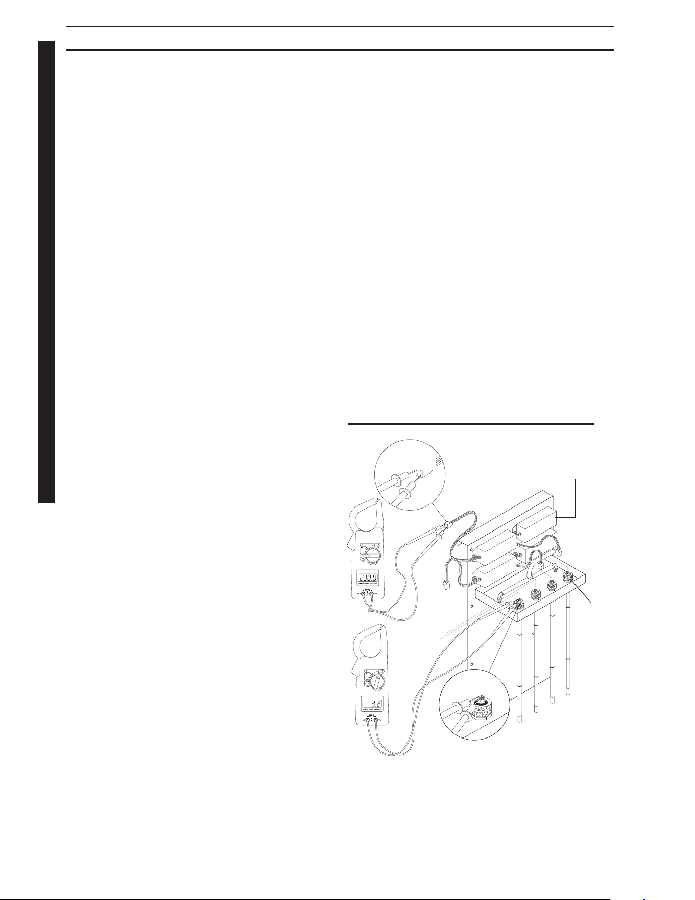
Testing the Lamp:
(See Ozone Generator Testing Illus.)
To test the ozone lamp, use a voltmeter set on ohms. First remove
the ozone cover and unplug the lamp plug from the ozone lamp.
NOTE: There are two fi laments - an upper and a lower - inside
the lamp. Place one of the voltmeter leads on one of the lamp
prongs and, with the other lead, touch all of the three remaining
prongs. If continuity is not achieved on both upper and lower
fi laments, replace the ozone lamp (Part #6-0534).
To test the power pack, use a voltmeter set on the correct voltage
(240V). Place one of the voltmeter leads into the lamp plug where
the white wire goes into it and plug the other voltmeter lead into
the lamp plug where the blue wire goes into it. If no voltage is
present replace the ozone ballast (Part #6-05232 - 240V). When
ordering an ozone ballast, you also need the 4-pin connector
(Part #6-05233).
Replacing the lamp: (See Ozone Generator Breakdown)
89144580-39
Ozone
Lamp
Prongs
Ballast
OZONE GENERATOR TESTING
Four Pin
Connector
OZONE GENERATOR
Ozone...Nature’s Purifi cation Agent:
Ozone is produced in nature or artifi cially by man. In the earth’s
atmosphere, ozone is formed when oxygen is exposed to ultravio-
let light or an electrical charge as during thunderstorms. Ozone’s
primary function in nature is to purify the air we breathe and
screen us from harmful rays of the sun. In a similar fashion, the
CLB system uses ozone to disinfect water because
Ozone has a
number of characteristics that make it ideal for water treatment.
Ozone’s Characteristics:
Ozone is well suited for water treatment, and it’s unique charac-
teristics are described below:
• Ozone works up to 3,000 times faster than chlorine to kill
bacteria and destroy harmful microorganisms.
• Ozone is a more powerful oxidizing agent than chlorine
and bromine, having a better ability to remove water
contamination.
• Ozone will not form harmful by-products, like THM’s (a
problem in drinking water), or chloramines, (by-products
of chlorine that are responsible for odors, skin irritations
and burning eyes.)
• Ozone will not alter the water’s pH, reducing pH fl uctua-
tions.
• Ozone coagulates small particles in water so clarity is
dramatically improved.
• Ozone acts as a deodorizer removing unpleasant odors
from water.
How the CLB Ozone System Works:
Because ozone is unstable, it cannot be packaged and used at
a later date. For this reason, ozone is always produced where it
is utilized.
Point-of-use ozone generation is simple. This powerful disinfectant
is produced from ambient air surrounding the generator using
special ultraviolet lamps located inside the system’s cabinet. To
generate the ozone, air movement is created through the use of an
air compressor or water venturi. As air passes over these unique
lamps, the oxygen contained in the air is converted. The result-
ing ozone gas is subsequently introduced to the water in the inlet
pipeline, where oxidation and disinfection immediately take place.
Ozone Generator Maintenance:
CAUTION: Never look at the unshielded ozone
lamp while operating the machine. This lamp can
cause severe eye and skin damage. The indica-
tor light will be a dim green or not lit at all when
operating properly. The light glows a bright green
when there is a failure. See product description for
location of the indicator light.
8.914-458.0-G • Water Maze CLB-603
33
WATER TREATMENT SYSTEM
OPERATOR’S MANUAL
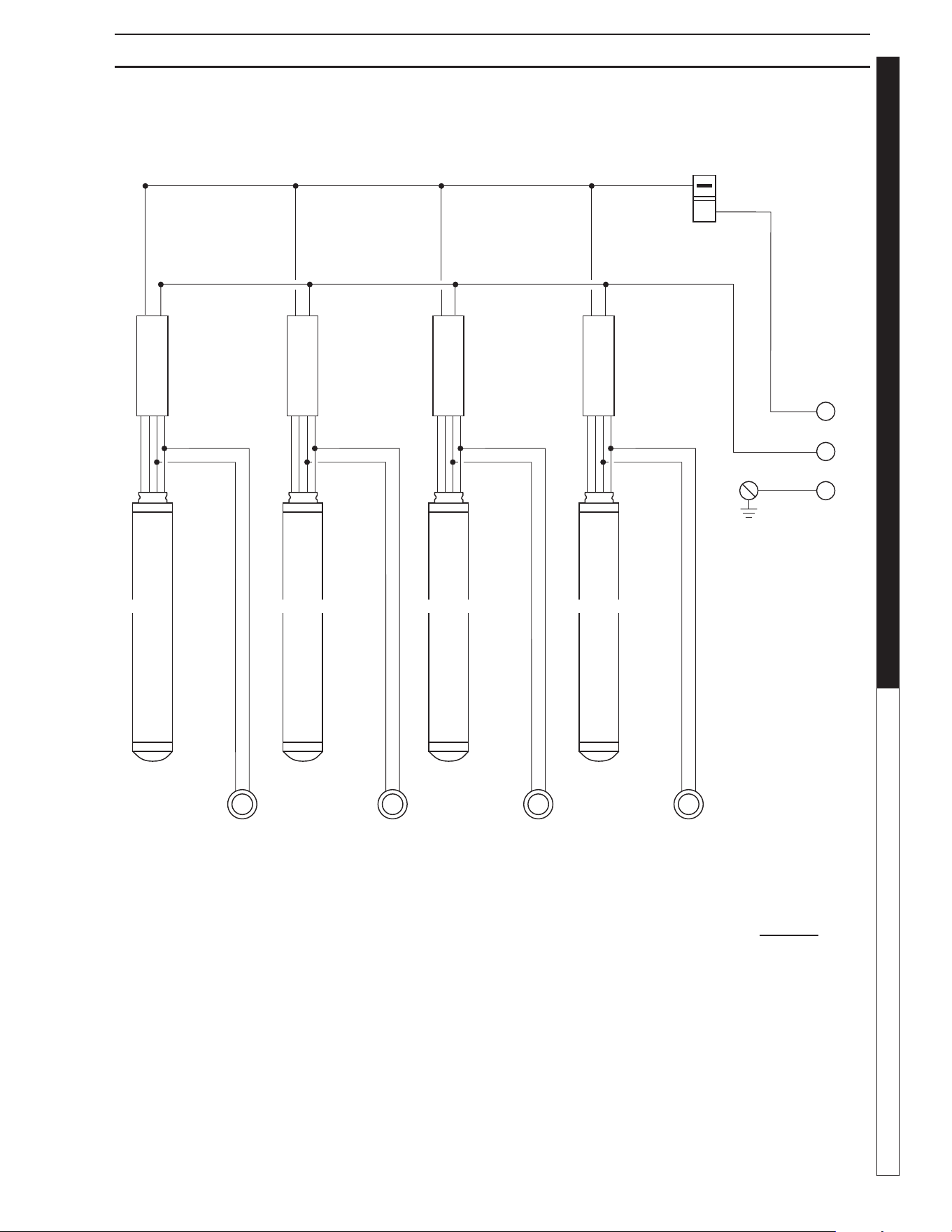
OZONE GENERATOR FOUR TUBE
Power
In
LEGEND:
B = Black
W = White
R = Red
G = Green
Y = Yellow
BL = Blue
89144580-37
Transformer
RYW
Transformer
RYW
Transformer
RYW
Transformer
RYW
B
B
Control
Switch
BLBLBL BL
B
W
G
Ground
W
B
W
B
W
B
W
B
Indicating Lights
NOTE:
Green Indicating Light Operation
Bright Continuous Light Indicates
UV Light of Ballast Defective
Dim Continuous Light Indicates
Proper Operation
Ozone LightOzone Light Ozone LightOzone Light
8.914-458.0-G • Water Maze CLB-603
OPERATOR’S MANUAL WATER TREATMENT SYSTEM
34
Lamp replacements are available from your Water Maze Dealer
should they need to be replaced. Simply turn off the power to the
CLB at the breaker, remove the screws on the power pack cover
and remove the cover. Disconnect the plug on the end of the
ozone lamp. Now, loosen the lamp holder locking ring from around
the end of the lamp by turning it counterclockwise and remove it.
Remove the lamp by grabbing the rubber bushing around the end
of the lamp and pulling it straight out. Remove the rubber bushing
from the lamp and install it on your new lamp, making sure the
outer edge of the bushing is fl ush with the outer edge of the silver
end cap on the lamp. Now, slide the lamp back into the reaction
chamber. The lamp holder may now be reinstalled and tightened.
Reinstall the plug onto the lamp and replace the power pack cover.
CAUTION: Keep the lamp free of fi ngerprints and
dust particles by only handling the metal end caps
on the lamp. You can clean the lamp with rubbing
alcohol and a soft cloth. A dirty lamp will not allow
maximum ozone output.
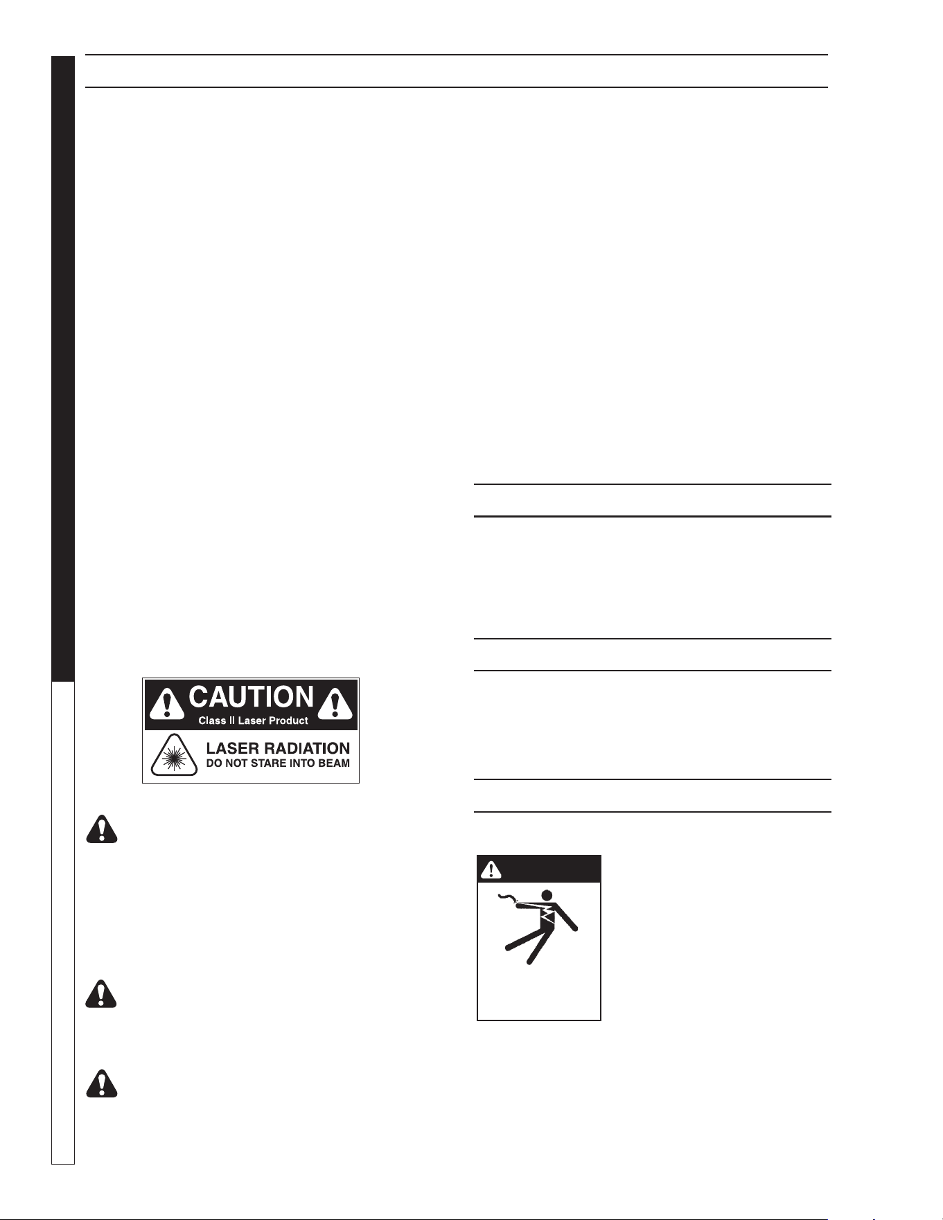
ULTRAVIOLET LIGHT
COMPLIANCE
Ultraviolet Light Safety Requirements
The device used in this product is a Class 1 certi-
fied ozone generator product. Operating this product out-
side specifications or altering its original design may result
in hazardous radiation exposure, and may be consid-
ered an act of modifying or new manufacturing of a laser
product under U.S. regulations contained in 21CFR
Chapter 1, subchapter J.
CAUTION: Avoid exposure to direct or
strongly refl ected germicidal ultraviolet
rays.
DO NOT STARE INTO BEAM.
ATTENTION: Éviter l'exposition aux rayons ultra-
violets germicides fortement réfl échis.
NE PAS REGARDER DIRECTEMENT LE FAIS-
CEAU.
DANGER: Ultraviolet radiation. Disconnect
Power Before Replacing Lamp.
ATTENTION: Radiation ultraviolette. Débrancher
l'alimentation avant de remplacer la lampe.
DANGER: Connect only to a circuit that is
protected by Ground Fault Circuit Interrupt
(GFCI).
DANGER: Raccorder uniquement à un circuit qui
est protégé par un disjoncteur diff érentiel de
fuite à la terre (DDFT).
Instructions for Disposing of Your UV
Light Tube
1. Do not break a UV light tube. Keep all tubes whole if pos-
sible. If a UV light tube is accidentally broken, wear gloves
while picking up the pieces, and carefully dispose of them in
a trash bag. Wipe the area with a wet wipe, and put the wet
wipe in the same trash bag. Place the trash bag with broken
pieces inside another trash bag. Mark the bag with a sign
labeled, "Broken Mercury Light Bulb".
2. Remove the UV light tube from the Ozone Genera-
tor. Place the used tube in the trash bag, and place
that bag inside another trash bag. Seal the openings
and then tape a slip of paper on the outer bag labeled,
"Mercury LIght Bulb."
3. Take the used and /or broken mercury tube to your nearest
recycling bin for mercury light bulbs or take this tube to a
state-approved recycling center.
SPECIFICATIONS:
Energy Required 220V: 210VAC MIN., 230V MAX.,
.450AMP/Ballast
Power Consumption: 20 Watts
Average Lamp Life: 9,000 Hours
CENTRIFUGAL PUMP
Your centrifugal pump has been quality-built and engineered to
give you effi cient, dependable service. It is equipped with union
connectors to make installation and future service easier.
The advanced design uses a single speed motor which reduces
operation and maintenance to simple, common-sense procedures.
PUMP OPERATION
(Ozone, Infeed, or Transfer)
WARNING: Do not touch
pumps, pump motors, water
or discharge piping when the
pumps are connected to elec-
trical power. Do not handle a
pump or pump motor with wet
hands or when standing on
a wet or damp surface or in
water. Never touch a pump or
discharge piping when a unit is
operating or fails to operate. Always disconnect
the pump cord (power) before handling.
AVERTISSEMENT : Ne touchez pas les pompes,
les moteurs de pompe, les conduites d'eau ou de
WARNING
RISK OF ELECTRIC
SHOCK: USE
CAUTION WHEN
HANDLING.
OZONE GENERATOR
8.914-458.0-G • Water Maze CLB-603
35
WATER TREATMENT SYSTEM
OPERATOR’S MANUAL
WARNING
RISK OF ELECTRIC
SHOCK: USE
CAUTION WHEN
HANDLING.
refoulement lorsque les pompes sont connectées
à l'alimentation électrique. Ne manipulez pas une
pompe ou un moteur de pompe avec les mains
mouillées ou lorsque vous vous tenez sur une
surface mouillée ou humide ou dans l'eau. Ne
touchez jamais une pompe ou une tuyauterie de
refoulement lorsqu'une unité fonctionne ou ne
fonctionne pas. Débranchez toujours le cordon de
la pompe (alimentation) avant toute manipulation.
1. The shaft seal depends on water for lubrication. Do not oper-
ate the pump unless there is water. Dry running (pump not
pumping water) will cause seal damage and eventual pump
failure.
2. The motor is equipped with an automatic reset thermal protec-
tor. This means if the temperature in the motor should rise
unduly, the switch will cut off all power before damage can
be done to the motor. When the motor has cooled suffi ciently,
the switch will reset automatically and restart the motor. If
the protector trips repeatedly (cycling on protector) the pump
should be removed and checked as to the cause of the dif-
fi culty. Low voltage, long extension cords, clogged impeller,
very low head or lift, etc., could cause cycling. Cycling of the
protector will cause eventual motor burnout.
PUMP MAINTENANCE
(Sump Pump)
WARNING: Before attempting
to service, disconnect power
from unit. Do not handle the
pump with wet hands or when
standing on a wet or damp
surface or in water. Failure to
follow precautions can result
in personal injury and /or
property damage.
AVERTISSEMENT: Ce produit et les accessoires
peuvent contenir un produit chimique reconnu
dans l'État de la Californie comme pouvant
causer le cancer, des anomalies congénitales et
d'autres problèmes liés à la reproduction. Pour
en savoir plus sur ce règlement. Le non-respect
des précautions peut mener à des lésions
corporelles et/ou des dommages à la propriété.
NOTE: Only qualifi ed electricians or servicemen should attempt
to repair this unit. Improper repair and/or assembly can cause an
electrical shock hazard.
1. Bearings in this unit are pre-lubricated. No additional lubrica-
tion is necessary.
2. Cleaning - Occasionally clean the sump pit and pump if dirt or
foreign matter accumulate. Small stones, gravel, sand, dirt, silt,
etc. can clog and damage the pump and pump seal, eventually
causing pump failure.
3. Disassembly of the motor prior to expiration of the warranty
will void the warranty. It may also cause internal leakage and
damage to the unit. If repairs are required, return the pump
to a local service station.
4. If the motor has been disassembled or the switch chamber
opened after the warranty expiration date, the O-rings and
gaskets must be replaced. Care must be taken to assure that
the seals, the switch cover and air tube gaskets do not leak.
5. The pump should be checked for proper operation weekly or
monthly by watching the operation of the pump. If anything
has changed since the pump was new, the pump should be
examined, and repaired if necessary.
Operation
The pH of the water stream is controlled automatically by the
digital controller. The controller receives input from the pH sen-
sor on the pH level of the digester tank. The level of pH being
sensed, and the requested level programmed in the controller will
determine if output from the controller is sent to the feed pumps.
If pH adjust is needed, the output will turn the corresponding feed
pump on. This will inject the required pH until the programmed
level is reached and feed pump will stop.
Start-Up
Turn switch on right side of controller to the "ON" position.
Feed Mode
The feed mode for the sanitizer of pH can be set to "OFF", manual
or Automatic. Set to Automatic. To select the desired feed mode,
press [pH] until the corresponding LED indicator light is illumi-
nated. There is a short delay before activation. Note: Holding the
switch for more than 5 seconds resets the setpoint and calibration
for [pH] to original factory values.
pH Calibration
To calibrate the pH, use a reliable, fresh test kit (Phenol Red). Note
the value of the pH and compare it to the display value.
To change the pH calibration:
• press [CALIBRATION],
• Press [pH]: the display fl ashes,
• Use the [UP] and [DOWN] arrows to adjust the pH value,
• Press the [CALIBRATION] again to save the new value.
pH Control Setpoint
The pH setpoint is preset at 7.0. To change the pH control setpoint:
• Press [SETPOINT],
• Press [pH]: the display fl ashes,
• Use the [UP] and [DOWN] arrows to adjust the pH value,
• Press [SETPOINT] again to save the new value.
OPTIONAL pH DIGITAL CONTROLLER - MODEL 240
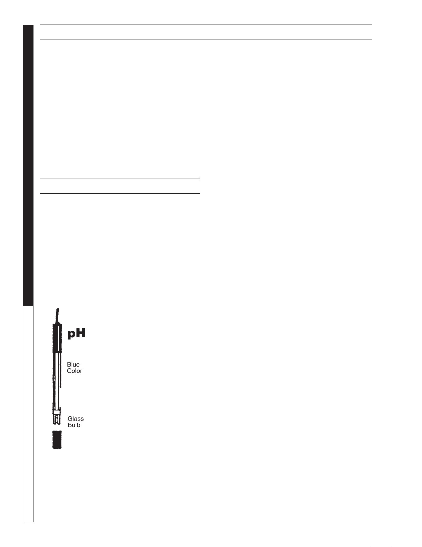
8.914-458.0-G • Water Maze CLB-603
OPERATOR’S MANUAL WATER TREATMENT SYSTEM
36
Out-of-Range Alarms
The out-of-range alarms is factory set at 6.0 to 9.0 for pH. If the
pH limits are exceeded, the red LED alarm fl ashes and the pH
feeder continues.
To change an alarm limit:
• Press [LOW LIMIT] or [HIGH LIMIT],
• Use the [UP] and [down] arrows to adjust the value,
• press [LOW LIMIT] or [HIGH LIMIT] again.
CAUTION: Increasing the out-of-range limits may
cause overfeeding of chemicals.
ATTENTION: L'augmentation des limites hors de
portée pourrait entraîner la suralimentation en
produits chimiques.
pH SENSOR MAINTENANCE
The controller is virtually maintenance free. The enclosure and
front panel can be cleaned with a soft cloth moistened with a mild
soap and water solution or a glass cleaner. Do not use abrasives
or harsh chemicals.
Sensor Testing
To test the sensors on line, carefully add a small amount of white
vinegar or dilute acid solution in a clean jar and insert sensor. After
a few minutes the pH reading should go DOWN.
If you get no response or a sluggish response, clean or replace
the sensors as soon as possible.
Sensor Cleaning
The sensor tips must be kept clean
and free from chemical deposits and
contamination to function properly. After
saturation in the waste stream, the sen-
sors may need to be cleaned on a weekly
or monthly basis depending on the water
quality and other facility-specifi c charac-
teristics. Slow response and inconsistent
readings are indications that the sensors
are in need of cleaning.
To clean a sensor, carefully remove it
from the compression fi tting or holding
bracket. Clean the tip of the sensor with
a mild liquid detergent (Joy
®
, etc) solu-
tion. Rinse with fresh water and soak
the sensor in a mild acid solution for
fi ve minutes. Rinse with fresh water and
reinstall the sensor.
Sensor Replacement
For preventative maintenance it is also recommended to replace
the sensors on an annual basis or as performance diminishes.
OPTIONAL pH DIGITAL CONTROLLER - MODEL 240
66-122
Plastic Cap
with Water
Sensor Storage
Extended exposure to atmospheric conditions will cause the sen-
sor tips to dry out. Always remove and properly store the sensors
if they are to be winterized or inactive.
Store the sensors with the original cap provided, making sure that
each cap is fi lled with clean water. If the storage containers have
been misplaced, store the sensors individually in small glass or
plastic containers with clean water covering the sensor tips.
8.914-458.0-G • Water Maze CLB-603
37
WATER TREATMENT SYSTEM
Troubleshooting Guide
TROUBLESHOOTING - PH SENSOR
All controllers are manufactured to the highest quality standards and thoroughly tested before leaving the factory. State-of-the-art
designs and fabrication technology should ensure years for trouble-free operation.
PROBLEM
SOLUTION
NO LIGHTS
ARE ON WITH
POWER ON
Check for power going to controller.
Check for a damaged power connector.
Check internal fuse (1A slow blow) marked F3 on control board.
ILLOGICAL pH
VALUE DISPLAY
The sensor cable connections may be reversed. Verify that the sensor cables are properly con-
nected to their respective BNC connectors on the controller unit.
pH FEEDER
DOES NOT
ACTIVATE
Verify that the acid/base feed jumper JP14 on the control board is properly set.
Make sure the AUTO feed light for pH is on.
Check the pH relay fuse (5A slow blow) marked F2 on control board
pH REQUIRES
FREQUENT
CALIBRATION
Clean or replace the sensor as outlined in the maintenance section.
INCONSISTANT
OR SLOW pH
READINGS
Verify that the sensor cables are properly connected to their respective BNC connectors and the
controller unit.
Clean or replace the sensor as outlined in the maintenance section.
Replace the sensors if needed.
CHEMICAL
FEEDER RUNS
CONTINUOUSLY
Make sure the AUTO feed mode is selected.
Verify that the chemical feeders are properly connected to their respective connectors or controller
unit.

8.914-458.0-G • Water Maze CLB-603
WATER TREATMENT SYSTEM
Troubleshooting Guide
38
PROBLEM POSSIBLE CAUSE SOLUTION
INFEED PUMP
DOES NOT
OPERATE
Low level in CLT-300 tank Check level in CLT-300 tank. Pump will not operate
at low water level.
LS1 has improper electrical
connection to JB#2
Connect LS1 to connections located in junction box
#2.
Control panel pump switch is in the OFF posi-
tion
Confi rm that control panel pump switch is in the ON
position.
OZONE PUMP
DOES NOT
OPERATE
Ozone timer is not set properly Refer to instructions on setting ozone pump timer.
Recycle holding tank has low water level Low water level will not allow the ozone pump to
operate. Raise level in recycle holding tank.
Control panel pump switch is in the OFF posi-
tion
Confi rm that control panel pump switch is in the ON
position.
TRANSFER PUMP
DOES NOT
OPERATE
Recycle holding tank has low water level Low water level will not allow the transfer pump to
operate. Raise level in recycle holding tank.
Water panel hand valve (V4 or V5) open but
pump does not start, or hand valve is closed
but pump does not stop
Pressure switch (PSI) is out of
adjustment. Readjust.
Control panel pump switch is in the OFF posi-
tion
Confi rm that control panel
pump switch is in the ON position.
TROUBLESHOOTING - INFEED, OZONE AND TRANSFER PUMP
8.914-458.0-G • Water Maze CLB-603
39
WATER TREATMENT SYSTEM
Troubleshooting Guide
TROUBLESHOOTING - PUMP
PROBLEM POSSIBLE CAUSE SOLUTION
PUMP DOES
NOT TURN ON
Circuit breaker shut "OFF" Turn "ON" circuit breaker.
Accumulation of trash on fl oat Clean fl oat.
Float obstruction Check fl oat path and provide clearance.
Defective switch Have pump serviced by authorized service center.
Defective motor Have pump serviced by authorized service center.
Low line voltage If voltage under recommended minimum, check size of wiring
from main switch on property. If OK, contact power company.
PUMP WILL
NOT SHUT OFF
Float obstruction Check fl oat and fl oat rod path. Provide clearance.
Pump is air locked
(Transfer and Infeed Pump)
Shut power off for approximately 1 minute, then
restart. Repeat several times to clear air from pump.
Defective fl oat switch Disconnect switch, check with ohmmeter.
PUMP RUNS BUT
DOES NOT
DISCHARGE
LIQUID
Lift too high for pump Check rating table.
Inlet to impeller plugged Pull pump and clean.
Low line voltage If voltage under recommended minimum, check size of wiring
from main switch on property. If OK, contact power company.
Clogged impeller Remove housing, unclog.
Faulty motor protector Replace pump.
PUMP DOES NOT
DELIVER RATED
CAPACITY
Low voltage, speed too slow Check for proper supply voltage to make
certain it corresponds to nameplate voltage.
Impeller or discharge pipe
is clogged
Pull pump and clean. Check pipe for scale or
corrosion.
Impeller wear due to abrasives Replace worn impeller.
PUMP CYCLES
CONTINUALLY
Low line voltage If voltage under recommended minimum, check size of wiring
from main switch on property. If OK, contact power company.
Worn or defective pump parts
or plugged impeller
Replace worn parts or entire pump. Clean parts if required.
Pump air locked Turn pump "ON" and "OFF" several times. Fill hose manually
with water.
8.914-458.0-G • Water Maze CLB-603
WATER TREATMENT SYSTEM
Troubleshooting Guide
40
TROUBLESHOOTING - PUMP MOTOR
PROBLEM POSSIBLE CAUSE SOLUTION
MOTOR WILL
NOT RUN
Disconnect switch is "OFF" Be sure switch is on.
Breaker is tripped Reset breaker.
Starting switch is defective Replace starting switch.
Wires at motor are loose, disconnected or
wired incorrectly
Refer to instructions on wiring. Check and tighten all wiring.
Pressure switch contacts are dirty (Trans-
fer Pump)
Clean by sliding piece of plain paper (or crocus cloth) be-
tween contacts.
MOTOR RUNS
HOT AND
OVERLOAD
KICKS OFF
Motor is wired incorrectly Refer to instructions on wiring.
Voltage is too low Check with power company. Install heavier wiring if wire size
is too small. See wiring instructions.
Defective fl oat switch Disconnect switch, check with ohmmeter.
MOTOR RUNS
BUT NO WATER
IS DELIVERED
Pump in a new installation did not pick up
prime through:
a. Improper priming a. Re-prime (3 or 4 times may be needed) by
stopping and starting motor several times.
b. Air leaks b. Check all connections on suction line.
Pump has lost its prime through:
a. Air leaks a. Check all connections on suction line, air
volume control, jet and shaft seal.
b. Water level below suction of
pump
b. Lower suction line into water and re-prime.
Check valve is stuck
in closed position
Replace check valve.
Pipes are frozen Thaw pipes. Bury pipes below frost line. Heat pipes below
frost line. Heat pit or pump house.
8.914-458.0-G • Water Maze CLB-603
41
WATER TREATMENT SYSTEM
Troubleshooting Guide
PROBLEM POSSIBLE CAUSE SOLUTION
VALVE LEAKS
WHEN "OFF"
Dirt or debris on diaphragm seat Clean diaphragm seat.
Solenoid not fully closed after manual
operation
Turn solenoid clockwise to fully seated position.
Solenoid O-ring damaged or twisted Turn off water, inspect O-ring. Reseat if twisted, replace if
damaged.
Diaphragm damaged Turn off water, remove bonnet screws and inspect
diaphragm for nicks or damage NOTE: Diaphragm has
one bleed hole molded into it. Replace, if necessary, with
diaphragm kit.
Dirt interfering with solenoid
operation
Turn off water, remove solenoid and fl ush seating surface
in bonnet and at bottom of solenoid with water.
Solenoid damaged Turn off water supply and replace solenoid.
WATER WON'T
SHUT OFF
Valve in manual "ON" position Turn solenoid clockwise to "OFF" position.
Diaphragm bleed hole blocked Use Manual Flush Mode. Turn water supply "OFF" and
immediately back "ON" to clear blockage. If still blocked,
turn off water and
inspect diaphragm looking for blockage.
Damaged solenoid Turn off water supply and replace solenoid.
LOW OR
INADEQUATE
FLOW CONDITION
Gate valve not fully open Open gate valve fully.
Pipeline blockage Clear pipeline.
VALVE WON'T
TURN ON
ELECTRICALLY
No power to solenoid Make sure solenoid has power.
Low voltage Make sure there is 120 volts.
No water pressure Make sure water pressure is available to valve. Turn off
water, without cutting wires, unscrew and swap solenoids
between valves. Turn on water and test again. If problem
stems from the solenoid, replace solenoid.
TROUBLESHOOTING - WATER SOLENOID

8.914-458.0-G • Water Maze CLB-603
WATER TREATMENT SYSTEM
Troubleshooting Guide
42
PROBLEM POSSIBLE CAUSE SOLUTION
CRACKED
OR BROKEN
STATIONARY
SEAT (CERAMIC)
Seal ran dry and heated up. When
liquid reached seal faces it was cooler,
causing thermal cracks
Check to insure seal chamber is full of liquid before starting
pump. On high temperature application insure proper fl ush-
ing at seal faces.
CARBON WASHER
SCORED AND
GROOVED
Dirty system Have system cleaned and fl ushed. Consider use of Tung-
sten Carbide or Silicon Carbide Rings.
CARBON
WASHER WORN
UNEVENLY
Seal improperly installed Check installation instructions for proper
assembly.
BUNA DIAPHRAGM
HARD BRITTLE.
RAPID CARBON
WEAR.
Air leak on suction side of pump Check cover gasket, hand knobs, hose, clamps, etc. Re-
place or tighten as necessary.
DIAPHRAGM
SOFT AND STICKY;
APPEARS TO
BE DISSOLVING.
Bellows not compatible with material
being pumped
Consult dealer for recommendation advising of pumpage
and temperature.
TROUBLESHOOTING - WATER SEALS

8.914-458.0-G • Water Maze CLB-603
43
WATER TREATMENT SYSTEM
OPERATOR’S MANUAL
DAILY MAINTENANCE
To keep your Bio-System in peak performance you need to perform
minimal daily maintenance. This service is best performed each
morning before using the wash area..
- Check and clean catch basin and trench.
- Empty the debris dumpster.
- Wash down front and back of hydro-screen, preferably with a
pressure washer.
WEEKLY MAINTENANCE
- Check that purge drain valves work properly.
- Check that timers are set properly.
MONTHLY MAINTENANCE
Monthly maintenance for the Bio-System and replenishment of
BioStax 1800 is required. Schedule a regular day and time each
month to perform the maintenance. Record your maintenance in
the monthly log to provide a record in the event of an inspection.
- Replenish BioStax 1800.
- Replenish BioNutrient.
- Check the automatic microbe dispenser pump and make sure
the tubing is not cracked or worn. Replace tubing if required
(every 6-12 months). Clean screen in tubing going in microbe
bucket.
- Visually inspect external hoses and fi ttings.
- Confi rm pressure switch setting on transfer pump.
CLB MAINTENANCE

8.914-458.0-G • Water Maze CLB-603
OPERATOR’S MANUAL WATER TREATMENT SYSTEM
44
CLB MAINTENANCE
DAILY WEEKLY
MONTHLY
BI-YEARLY
Check pits for water level (Overfl ow/dry).
X
Check for voltage to machine
and that control panel switches are on.
X
Check all plumbing for leaks.
X
Check inlet fl ow meter for
proper fl ow. Clean meter if needed.
X
Check that inlet and discharge
manifold hoses and valves are in proper position.
X
Check ozone generator bulb.
Bright light-replace. Dim light good.
X
Clean and test pH probe if applicable*.
X
Suction pits of sludge and debris.*
X
Check and clean sump pump of dirt and debris.*
X
Clean fl oats in sump if accumulating dirt or grease. *
X
Check fl oat wires for cuts or frays.
X
Check and clean chemical injectors.
X
Check tubing on pH controller for splits or cracking.
X
Check standard cubic feet per
hour (SCFM) on ozone generator.
X
Check surge tank pressure.
X
Check transfer pump switch settings.
X
Open drain valve to purge solids.
X
Empty debris dumpster
X
Pressure wash front and back of debris dumpster.
X
Clean trench
X
Check timers for proper settings
X
Replenish BioStax 1800 and BioNutrient if applicable*
X
* Note: this is a guide. Depending on your wash load these items may have to be done more or less often.
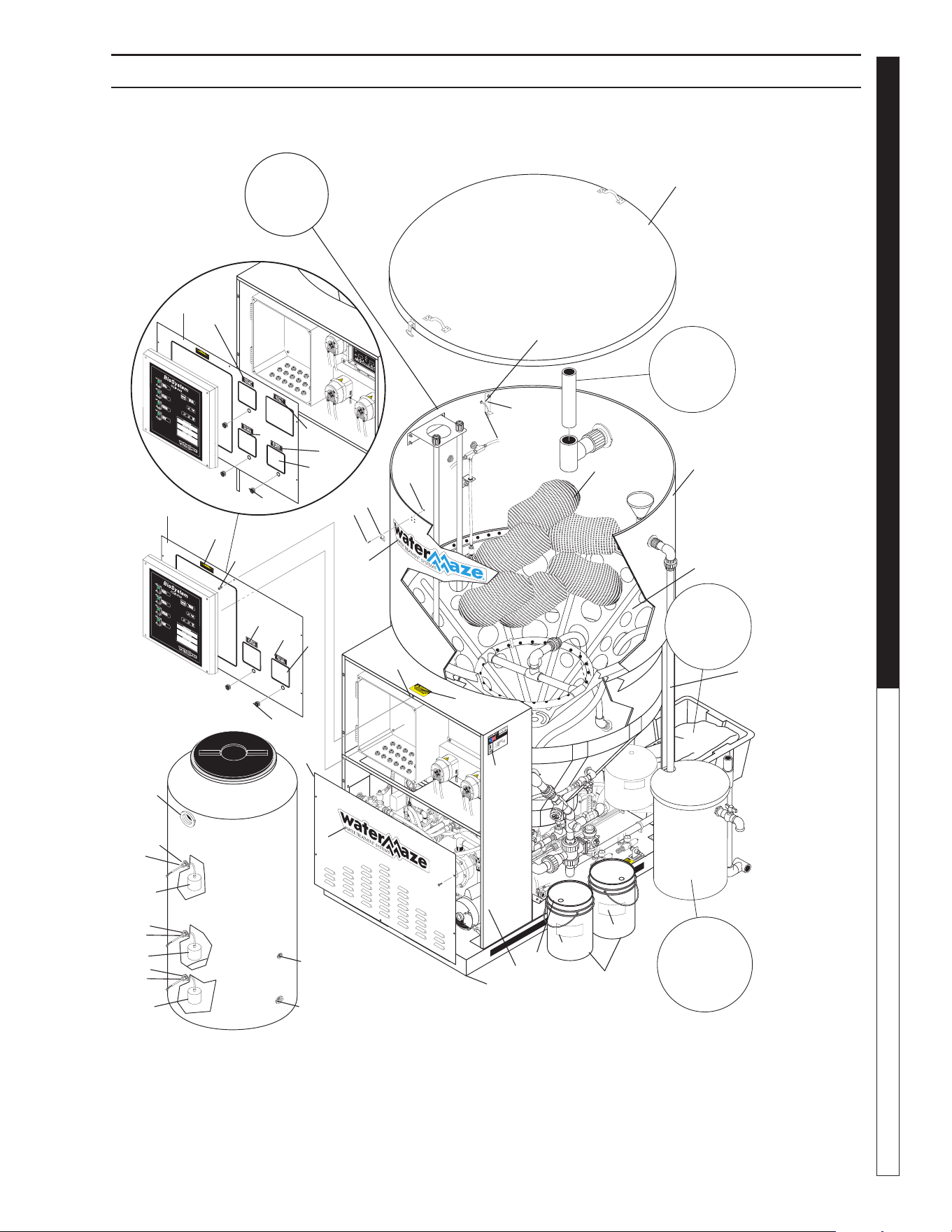
8.914-458.0-G • Water Maze CLB-603
45
WATER TREATMENT SYSTEM
OPERATOR’S MANUAL
89144580-22
CLB-603 COMPONENT ASSEMBLY EXPLODED VIEW
Optional pH
Sensor & Bracket
Assy.
For Detail
See Opt. Oil
Skimmer
Sludge Tub
Assy. Illus
For Detail
See Opt.
Oil Skimmer
Sludge Tub
Assy. Illus
Recycle
Tank
Accessories
Included
with
CLB-603
Field
Installed
1
2
12,13,14
1
24
3
25
26
2
34
34
5
20
35
38
41
39
39
40
38
41
38
41
36
37
8
6
22
29
21
30
31,32,
33
23
4
16
18
15
17
19
11
10
9
7
27
28
25
26
2
20
For
Details See
Air Stone
Assembly

8.914-458.0-G • Water Maze CLB-603
OPERATOR’S MANUAL WATER TREATMENT SYSTEM
46
ITEM PART NO. DESCRIPTION QTY
1 8.913-151.0 Panel, Front Top, w/Cutout for pH
Controller (Option) 1
8.913-163.0 Panel, Front Top w/o Cutout for
pH Controller 1
2 9.802-071.0 Trim, Black 10.33 ft
(option) 14.33 ft
3 9.802-765.0 Screw, 1/4" x 1/2" BH SOC CS 12
4 9.802-793.0 Nut, Cage, 1/4" x 16 Ga 11
5 8.913-148.0 Front Panel, Bottom, Mild Steel 1
6 8.913-147.0 Control Panel, Mild Steel 1
7 8.913-155.0 Tank Stand 600, Mild Steel 1
8 8.913-146.0 Base Plate 1
9 8.902-236.0 Cone, 3/16 w/Holes 1
10 8.719-177.0 Tank, 600 Gal w/Lid 1
11 8.706-676.0 Plastic, Eofi ll 36 lb.
8.707-435.0 Bag, Pre-sewn 6
12 9.802-696.0 Nut, 10/32 Keps, SS 8
13 9.802-699.0 Screw, 10/32" x 3/4", Slot Pan 8
14 8.706-648.0 Handle, Sandpot Lid 3
15 8.718-854.0 Nut, 6/32, Keps 12
16 9.802-747.0 Screw, 6/32, Keps 12
17 8.716-905.0 Sensor, PH (Option) 1
18 8.706-568.0 Handle, Rubber w/Keeper 3
19 8.913-085.0 Bracket, PH (option) 12
20 8.900-841.0 Label, Water Maze 2
21 8.711-943.0 Bucket, 6-1/2 Gal 2
22 8.711-944.0 Lid, 6-1/2 Gal 2
23 8.900-522.0 Label, Warning, No Stand 1
24 9.800-016.0 Label, Warning, Electrical 1
25 8.901-222.0 Label, Microbe Pump 1
26 8.901-223.0 Label, Nutrient Pump 2
27 8.901-224.0 Label, pH Controller 1
28 8.901-225.0 Label, pH Pump 1
29 9.841-665.0 Label, Biostax 1800 1
30 8.900-615.0 Label, Bio-Nutrient 1
31 9.800-013.0 Label, Assembled, USA,
Intended for Indoor use 1
32 9.800-034.0 Label, Clear Lexan 1
33 Label, ETL 1
34 9.802-064.0 Grommet, Rubber Nozzle 2
(option) 1
▲ Not Shown
CLB-603 COMPONENT ASSEMBLY PARTS LIST
ITEM PART NO. DESCRIPTION QTY
35 8.706-483.0 Bulkhead, 3" Ft x Ft, Polypro 1
36 8.706-484.0 Bulkhead, 1" Ft x Ft, Polypro 1
37 8.706-490.0 Bulkhead, 1-1/2" Ft x Ft,
Polypro 1
38 8.750-743.0 Bulkhead, 1/2" NPT Polypro 3
39 8.716-142.0 Float Switch, Black, NO 2
40 8.716-143.0 Float Switch, Gray, NC 1
41 9.802-514.0 Strain Relief, LG Tite 3
RECYCLE TANK
ACCESSORIES
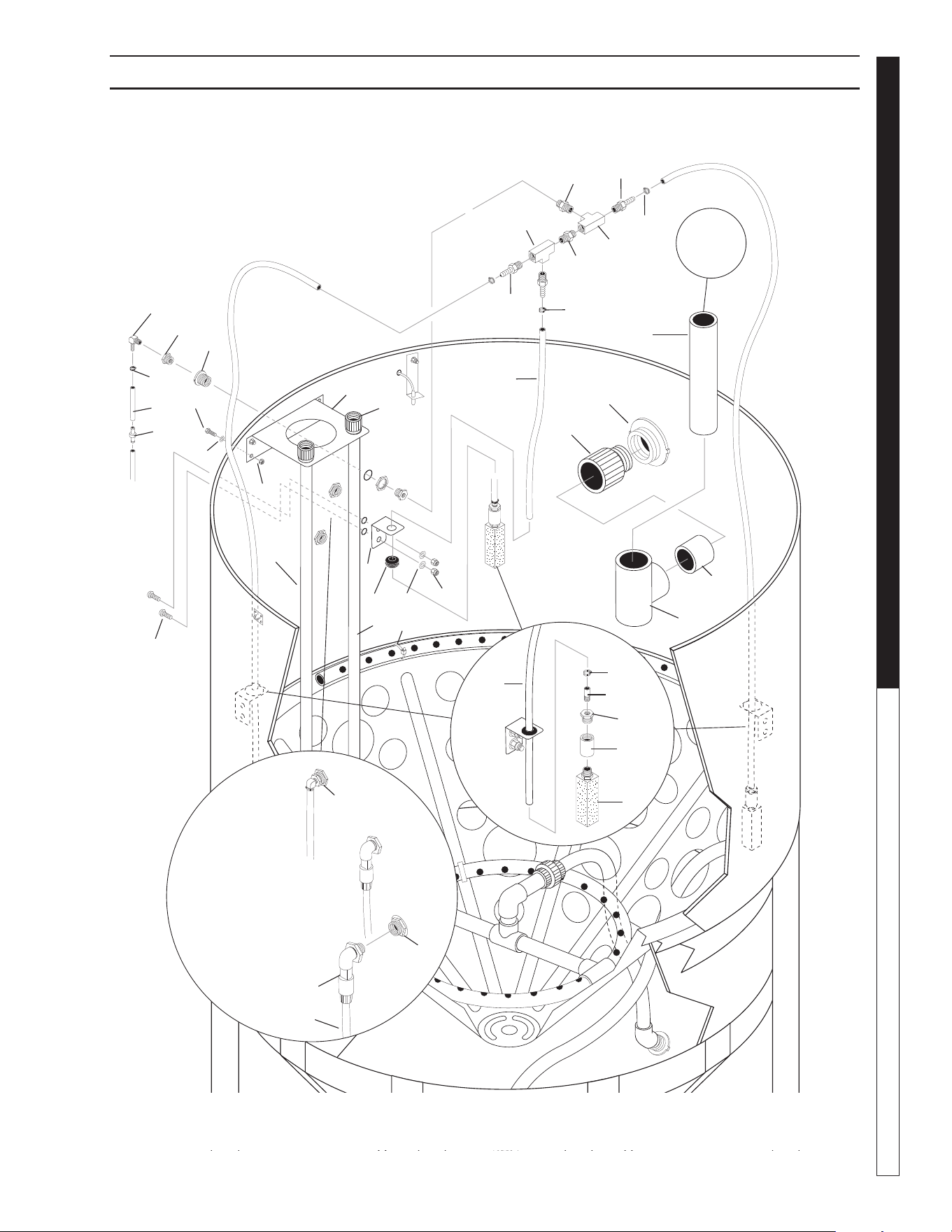
8.914-458.0-G • Water Maze CLB-603
47
WATER TREATMENT SYSTEM
OPERATOR’S MANUAL
89144580-20
24
33
Field
Installed
See CLB-603
Dimension
Page for
Layout
Dimensions.
6
10
22
CLB-603 AIR STONE ASSEMBLY EXPLODED VIEW
23
25
30
8
7
5
11
4
19
12
18
16
2
1
27
21
20
6
9
9
34
32
3
3
13
13
14
15
19
28
29
31
17
26
16
4
11
11

8.914-458.0-G • Water Maze CLB-603
OPERATOR’S MANUAL WATER TREATMENT SYSTEM
48
CLB-603 AIR STONE ASSEMBLY EXPLODED VIEW PARTS LIST
ITEM PART NO. DESCRIPTION QTY
1 8.711-733.0 Tubing, 3/8" x 1/2, Vinyl 10 ft
2 8.709-069.0 Clamp, Screw #4 3
3 8.706-780.0 Nipple, 1/4" Hex 2
4 9.802-254.0 Hose, 1/4" Push-on 16 in
5 8.706-878.0 Nipple, 1/4" Pipe x 1/8" Pipe 3
6 8.706-407.0 Bushing, 1/2 x 1/4 MT x FT 3
7 8.706-393.0 Coupling, 1/2" SCH 80 1
8 8.712-417.0 Diffuser Stone, Fine Pore,
1/2" NPT 3
9 8.750-743.0 Bulkhead, 1/2" Polypro 3
10 8.707-016.0 Elbow, 1/4 NPT x 3/8,
Push-On, 90° 1
11 6.390-126.0 Clamp, Hose 6
12 8.913-157.0 Bracket, Aerator 1
13 8.706-841.0 Tee, 1/4" Female, Pipe 2
14 9.802-064.0 Grommet, Rubber 3
15 8.919-140.0 Bracket, Air Stone 3
16 8.706-941.0 Hose Barb, 1/4" x 1/4" MPT 3
17 9.802-788.0 Nut, 3/8, Whiz Loc 8
18 8.706-409.0 Adapter, 1" MT x SLIP, PVC 2
19 8.706-366.0 Pipe, PVC 80, 1" x 48" 2
20 9.802-721.0 Bolt, 3/8 x 1", HH, NC, SS 8
21 9.802-808.0 Washer, 3/8", Flat, SS 8
22 8.706-483.0 Bulkhead, 3", FT x FT,
Polypro 1
23 8.706-454.0 Adapter, 3", Slip x MT,
PVC 40 1
24 8.706-437.0 Tee, 3" x Slip x Slip x Slip,
PVC 40 1
25 8.706-368.0 Pipe, 3", PVC 40 4 in
26 8.749-860.0 Check Valve, PVC
(w/pH Controlller) 1
ITEM PART NO. DESCRIPTION QTY
27 8.707-355.0 Valve, 3/8, Tubing,
Check MPC P/N 1
28 8.718-619.0 Bolt, 5/16" x 3/4"" NC,
GR 5 SS 6
29 9.802-805.0 Washer, 5/16" Flat, SAE, SS 6
30 9.802-511.0 Cable Tie, 11" 2
31 9.802-777.0 Nut, 5/16" ESNA, NC, SS 6
32 8.749-861.0 Bulkhead, 3/8 PVC,
w/Elbow, (w/pH Controller) 1
33 8.706-368.0 Pipe, 3", PVC 40 22 in
(Customer Installed)
34 8.749-857.0 Tubing, PE, 1/4, BLK,
1/4" x 7 ft 2
▲ Not Shown
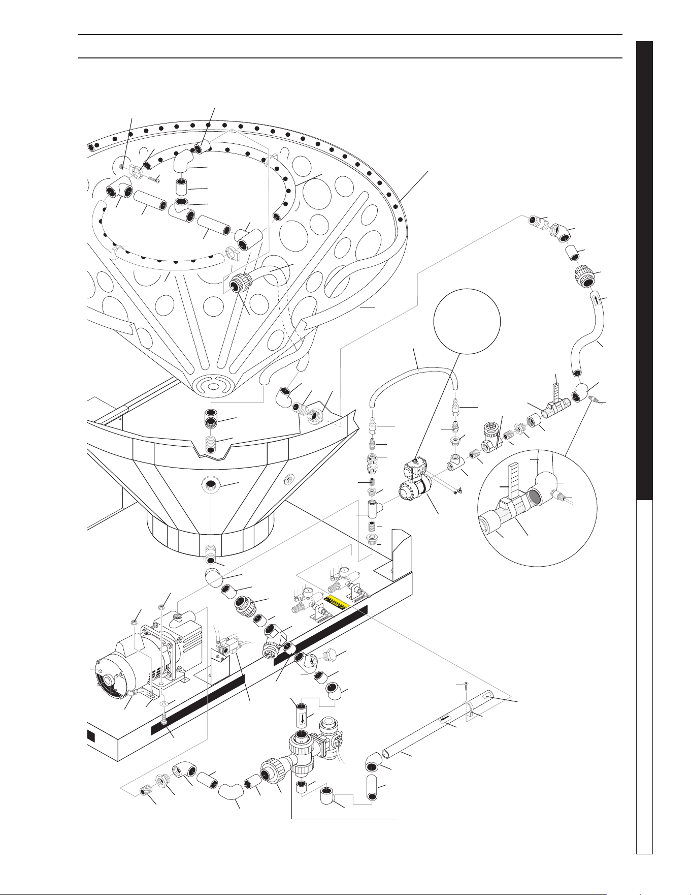
8.914-458.0-G • Water Maze CLB-603
49
WATER TREATMENT SYSTEM
OPERATOR’S MANUAL
89144580-10
See
CLB Air
Components
Exploded
View
Optional pH
Injector
(Enlarged
View)
57
13
51
15
22
14
15
14
49
50
37
11
10
41
18
12
11
44
11
26
25
40
31
37
45
13
33
52
4
34
47
5
36
35
4
52
38
52
43
38
20
47
47
33
56
4
35
36
16
See
CLB Air
Components
Exploded
View
See
CLB Air
Components
Exploded
View
31
28
28
41
25
40
34
4
52
33
52
32
52
31
6
27
27
1
39
42
30
7
2
38
3
4
55
5
19
8
45
54
52
5
53
31
9
45
23
24
17
43
52
12
21
CLB-603 INFEED PUMP ASSY EXPLODED VIEW

8.914-458.0-G • Water Maze CLB-603
OPERATOR’S MANUAL WATER TREATMENT SYSTEM
50
ITEM PART NO. DESCRIPTION QTY
1 8.715-387.0 Pump, Amt 1/2 HP, 115/230V
1 PH, 2852-95 Curve C 1
2 8.706-461.0 Nipple, 1-1/4" Close, PVC 80 1
3 8.706-415.0 Bushing, 1.5" MT x 1.25" FT,
PVC 80 1
4 8.706-372.0 Elbow, 1-1/2" S x T, PVC 80
90° 5
5 8.706-374.0 Elbow, 1-1/2" S x S, PVC 80
90° 3
6 8.706-428.0 Tee, 1-1/2" S x S x T 1
7 8.718-659.0 Bolt, 3/8 "x 1-1/4 NCH HSS 2
8 8.749-845.0 Valve, 3 Way Diverter
w/Actuator 1
9 8.706-367.0 Pipe, 1.5" PVC 80 19.5 in
10 8.706-405.0 Bushing, 1-1/4" x 1" MT x FT,
PVC 80 1
11 8.706-439.0 Nipple, 1" PVC 80, Close 3
12 8.706-429.0 Tee, 1" FT x FT x FT, PVC 80 2
13 8.706-928.0 Bushing, 1" x 1/2"
Black Poly Reducer 2
14 8.706-876.0 Nipple, 1/2" JIC x 1/2" MPT SS 2
15 8.707-005.0 Swivel, 1/2" JIC FEM
Push-on SS 2
16 9.802-259.0 Hose, 1/2" Push-on 24 in
17 8.706-394.0 Plug 1-1/2" PVC 80 1
18 8.756-649.0 Valve, Ball, 1", Pneu Act,
No Sol 1
19 8.706-367.0 Pipe 1.5 PVC 80 3.5 in
20 9.802-699.0 Screw 10/32" x 3/4" Slot Pan 4
21 9.802-696.0 Nut 10/32" Keps SS 4
22 8.902-236.0 Cone, 3/16 w/Holes 1
23 8.900-458.0 Label Inlet 1
24 9.802-799.0 Screw, #14 x 1" Tek Head 1
25 8.706-448.0 Adapter, 1.5 x 1.5 Ft x Slip 1
26 8.706-404.0 Bushing, 11/2" x 1" MT x FT,
PVC 80 1
27 9.802-788.0 Nut 3/8 " Whiz Loc SS 6
28 8.749-860.0 Check Valve
(w/optional pH Pump) 1
29 8.749-857.0 Tubing PE (option) Black 1/4" 7 ft.
30 9.802-808.0 Washer 3/8" Flat SS 2
31 8.706-379.0 Elbow, 1-1/2" SLIP x SLIP,
CLB-603 INFEED PUMP ASSY EXPLODED VIEW PARTS LIST
PVC 80, 45° 3
ITEM PART NO. DESCRIPTION QTY
32 8.707-344.0 Valve, PVC 1.5" SLIP x SLIP,
Gate 1
33 8.706-469.0 Union, 1-1/2" SLIP x SLIP,
PVC 80 3
34 8.706-468.0 Nipple 1.5" x 3" PVC 80 2
35 8.706-424.0 Nipple, 1.5" x Close, PVC 80 2
36 8.706-490.0 Bulkhead, 1-1/2" Polypro 2
37 8.711-815.0 Hose, 1-1/2" Gray Conduit 22 in
38 8.706-426.0 Tee, 1.5" S x S x S, PVC 80 3
39 9.802-517.0 Connector 1/2" LT 90° Black 1
40 8.712-136.0 Gauge, Flowmeter 1.5 1
41 8.706-360.0 Pipe 1.5 PVC Clear 8.5 in
42 8.913-161.0 Pump Plate 1
43 8.706-421.0 Hanger, 1-1/2" Pipe 5
44 8.707-343.0 Valve, 1" Gate, NPT 1
45 8.900-474.0 Label, Flow Arrow 3
46 8.711-815.0 Hose, 1-1/2" Gray, 32 in
47 8.706-367.0 Pipe, 1.5" PVC, (1.5" x 8") 2
48 8.706-455.0 Nipple 1" x 2" PVC 80 2
49 8.707-298.0 Valve, Ball Check 1/2" PVC 1
50 8.706-467.0 Nipple, 1/2" PVC 80, Close 1
51 8.711-815.0 Hose, 1-1/2" Gray Conduit 30 in
52 8.706-367.0 Pipe, 1.5" PVC 80 (1"x 2.5") 8
53 8.706-367.0 Pipe, 1.5" PVC 80 8 in
54 8.711-815.0 Hose 1 -1/2 Gray Conduit 6 in
55 8.706-367.0 Pipe, 1.5" PVC 80 4.5 in
56 8.711-815.0 Hose, 1-1/2" Gray, Conduit 32 in
57 8.711-815.0 Hose, 1-1/2" Gray, Conduit 108 in
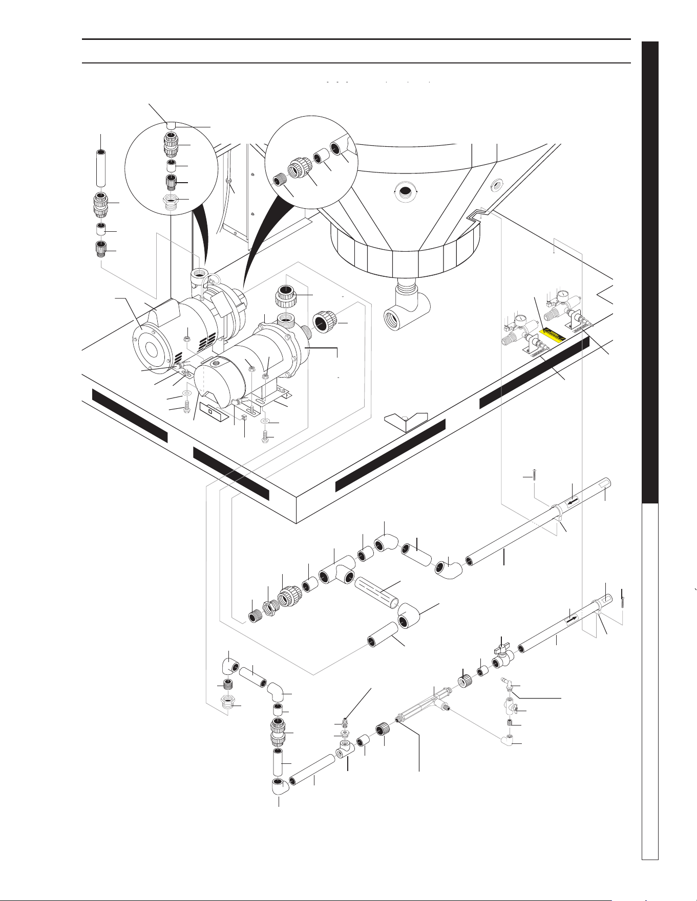
8.914-458.0-G • Water Maze CLB-603
51
WATER TREATMENT SYSTEM
OPERATOR’S MANUAL
89144580-17
30
7
37
CLB-603 TRANSFER/OZONE PUMP ASSY EXPLODED VIEW
Transfer
Pump
To Ozone
Generator
Mazzi
Injector
Assy
Ozone
Pump
To Water
Panel
To Manifold
Assy.
38
21
39
41
40
54
46
45
42
45
46
39
1
45
43
44
3
37
7
38
21
58
To Ozone
Generator
59
31
28
52
49
25
26
8
25
38
24
35
38
23
22
4
5
50
32
6
7
33
6
20
9
56
11
10
12
13
12
56
17
36
16
15
14
51
19
53
28
23
22
38
24
18
34
56
29
47
47
57
55
57
2

8.914-458.0-G • Water Maze CLB-603
OPERATOR’S MANUAL WATER TREATMENT SYSTEM
52
ITEM PART NO. DESCRIPTION QTY
1 8.755-986.0 PUMP, SCOT 11, 3/4HP 230V
1PH 4.88DIA 1
8.715-402.0 Pump, Scot 2 HP, 208/230 Volt
1 PH (Optional) 1
2 8.726-024.0 Pump, 3/4 HP, Wet End 1
3 8.726-026.0 Motor, 3/4 HP, 230V 1
4 8.706-378.0 Elbow, 1" SLIP x FIPT,
PVC 80, 90° 1
5 8.706-439.0 Nipple, 1", PVC 80 Close 1
6 8.706-373.0 Elbow, 1" S x S, PVC 80, 90° 2
7 8.707-300.0 Valve, 1" PVC Ball Check 2
8 8.706-367.0 Pipe, 1-1/2" PVC 80 4.5 in
9 8.706-430.0 Tee, 1" S x S x S, PVC 80 1
10 8.706-447.0 Adapter, 1" x 3/4" S x FIPT
PVC 80 1
11 8.706-899.0 Nipple, 3/4" JIC x 3/4" Pipe 1
12 8.706-444.0 Adapter, Female, 1" SLIP x FT
PVC 80 2
13 8.709-431.0 Injector, Ozone w/o Chk Valve 1
14 8.706-370.0 Elbow, 1/2" FIPT x FIPT,
PVC 80, 90° 1
15 8.706-587.0 Nipple, 1/2" x 1/4" 1
16 8.707-321.0 Valve, Ozone Meter, 1/4"
5310.002 Plastic 1
17 8.707-359.0 Valve, 1" S 80 PVC, S x S 1
18 8.706-374.0 Elbow, 1-1/2" S x S, PVC 80,
90° 1
19 8.706-423.0 Hanger, Pipe, 1" Click #32 1
20 8.706-366.0 Pipe, 1" PVC 80 7.5 in
21 8.706-409.0 Adapter, 1" MT x SLIP, PVC 80 1
22 8.706-461.0 Nipple, 1-1/4" x Close PVC 80 1
8.706-424.0 Nipple, 1.5" x Close PVC 80
(2 HP Option) 1
23 8.706-470.0 Union, 1-1/2" Slip x Thread
PVC 80 1
24 8.706-426.0 Tee, 1.5" S x S x S, PVC 80 1
25 8.706-379.0 Elbow, 1-1/2" SLIP x SLIP
PVC 80, 45° 2
CLB-603 TRANSFER/OZONE PUMP ASSY EXPLODED VIEW PARTS LIST
ITEM PART NO. DESCRIPTION QTY
26 8.706-367.0 Pipe, 1.5" PVC 26 in
27 8.905-717.0 Ozone Generator 230V 1 PH 1
28 8.900-474.0 Label, Flow Arrow 2
29 8.707-355.0 Ozone Check Valve 1
30 8.900-210.0 Label, Warning 1
31 8.901-115.0 Label, Air Valves Pressure
Regulator 1
32 8.706-366.0 Pipe, 1" PVC 80 7 in
33 8.706-366.0 Pipe, 1" PVC 80 4.5 in
34 8.706-367.0 Pipe, 1.5" PVC 80 4 in
35 8.706-360.0 Pipe, 1.5" PVC 80 Clear 8.5 in
36 8.706-588.0 Connector, 3/8" x 1/4"
Male Elbow 1
37 8.711-812.0 Hose 1" Gray Conduit 10 in
38 8.706-367.0 Pipe, 1.5" PVC 80
1-1/2 x 2-1/2 Spacer 3
39 8.913-161.0 Pump Plate 2
40 8.718-619.0 Bolt 5/16" x 3/4" NCGR, SS 4
41 9.802-805.0 5/16" Washer Flat SS 4
42 8.718-887.0 5/16" Whiz Loc 4
43 8.718-659.0 Bolt 3/8" x 1-1/4" NCHHSS 2
44 9.802-808.0 Washer 3/8" SS 2
45 9.802-788.0 Nut 3/8" Whiz Loc SS 10
46 9.802-517.0 Connector 1/2" LT 90° Black 2
47 9.802-799.0 Screw #14 x 1" Tek Head 2
48 8.706-424.0 Nipple, 1-1/2" Close, PVC 80
49 8.906-421.0 Hanger 1-1/2" Pipe 1
50 8.706-398.0 Bushing 1" FIPT x 1-1/2"
PVC 80 1
51 8.706-366.0 Pipe 1" PVC 80 13 in
52 8.900-458.0 Label Inlet 1
53 8.900-459.0 Label Outlet 1
54 9.802-794.0 Nut Cage 1/4" x 12 Ga 1
55 8.706-415.0 Bushing 1.5 MT x 1.25 PVC 80
(Not used with 2 HP Option) 1
56 8.706-366.0 Pipe 1" PVC 80 Spacer
1" x 2" 1
57 8.750-270.0 Fitting, Compression,
1-1/2" Slip 2
58 8.706-405.0 Bushing, 1-1/4" MT x 1" FT
PVC, Sch 80 (2 HP Option) 1
59 8.901-116.0 Label, Air Stone Diffuser
Pressure Regulator 1
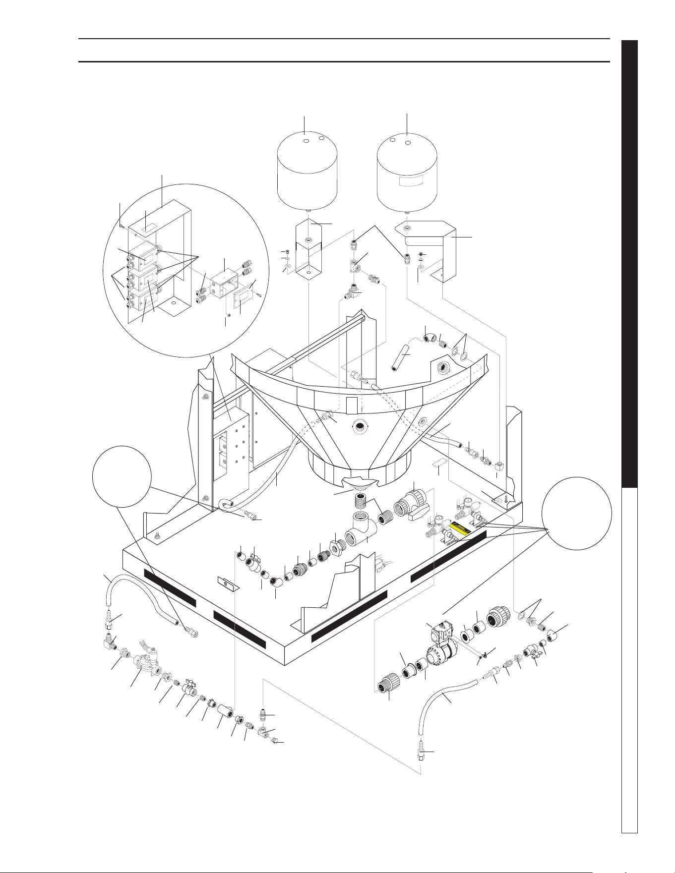
8.914-458.0-G • Water Maze CLB-603
53
WATER TREATMENT SYSTEM
OPERATOR’S MANUAL
89144580-26
Junction Box
Assembly
(Reverse View)
See
CLB Air
Components
Exploded
View
44
27
46
36
36
40
37
39
38
39
40
37
18
21
33
26
31
29
30
35
30
29
7
41
59
61
60
59
21
8
9
10
12
34
54
4
3
16
45
5
6
55
56
24
11
48
27
14
17
14
14
43
14
13
15
57
32
To
Manifold
Assembly
47
33
27
52
53
52
50
51
50
20
19
20
23
21
18
25
2
42
1
42
27
28
27
21
22
17
14
26
27
27
58
49
CLB-603 DRAIN SURGE TANK EXPLODED VIEW

8.914-458.0-G • Water Maze CLB-603
OPERATOR’S MANUAL WATER TREATMENT SYSTEM
54
CLB-603 DRAIN SURGE TANK EXPLODED VIEW PARTS LIST
ITEM PART NO. DESCRIPTION QTY
1 8.756-648.0 Valve, Ball, 1-1/2", Pneu Act,
No Sol 1
2 8.706-451.0 Adapter, 2" Slip x MT, PVC 80 1
3 8.716-547.0 Connector, 1/2" Straight 3
4 8.718-760.0 Screw, 10/32 x 5/8", Phil, SS 8
5 8.932-941.0 Label, WaterMaze, CLB-603
# 4, Junction Box 1
6 8.724-756.0 Label, WaterMaze, CLB-603
# 3, Junction Box 1
7 8.707-349.0 Valve, 2" Single Union Ball 1
8 8.706-466.0 Nipple, 2" Close, PVC 80 2
9 8.706-436.0 Tee, 2", FT x FT x FT, PVC 80 1
10 8.706-479.0 Bulkhead, 2" NPT, Polypro 1
11 9.802-483.0 Cover, Metal, 2" x 4",
Weather Proof 4
12 8.706-418.0 Bushing Reducer, 2 x 1,
PVC 80 MPT x FPT 1
13 8.706-409.0 Adapter, 1" MT x SLIP,
PVC 80 1
14 8.706-366.0 Pipe, 1" PVC 80,
1" x 2" Spacer 5
15 8.706-371.0 Elbow, 1" SxS, PVC 80 45° 1
16 8.724-755.0 Label, WaterMaze, CLB-603, #2,
Junction Box 1
17 8.707-359.0 Valve, 1" PVC S x S 2
18 8.706-846.0 Tee, 3/4" FIPT, Brass 2
19 8.706-430.0 Tee, 1" S x S, PVC 80 1
20 8.706-447.0 Adapter, 1" x 3/4" S x FIPT,
PVC 80 2
21 8.706-899.0 Nipple, 3/4" JIC x 3/4" Pipe 4
22 8.706-447.0 Adapter, 1", 3/4" S x FIPT
PVC 80 1
23 8.706-800.0 Nipple, 3/4" Hex, Brass 1
24 8.724-754.0 Label, WaterMaze, CLB-603, #1,
Junction Box 1
25 8.706-869.0 Plug, 3/4" Hex Head 1
26 8.706-378.0 Elbow, 1" SLIP x FIPT, PVC 80
90° 2
27 9.802-152.0 Swivel, 3/4" SAE Fem.
Push-on 8
28 9.802-261.0 Hose, 3/4", Push-on 36 in
29 8.706-439.0 Nipple, 1" PVC 80, Close 2
30 8.706-484.0 Bulkhead, 1" Polypro 1
31 8.706-366.0 Pipe, 1", PVC 80 12 in
32 8.706-823.0 Elbow, 3/4" Female 90° 1
ITEM PART NO. DESCRIPTION QTY
33 9.803-557.0 Elbow, 3/4" SAE x 3/4"
90° Brass 2
34 8.940-186.0 Label, Float, Switch,
Junction Box 1
35 9.802-261.0 Hose, 3/4" Push-on 30 in
36 8.719-176.0 Tank, 10 Gal Pre-pressurized,
Blue 2
37 8.719-021.0 Washer, 1/2, Lock 5
38 8.913-160.0 Bracket, Pressure Tank 1
39 8.718-997.0 Washer, 5/8, Flat 5
40 8.718-893.0 Nut, 1/2", SS, 304, Hex, NC 5
41 8.706-476.0 Union, 2", FSX FT, PVC 80 1
42 8.706-367.0
Pipe, 1.5", PVC 1.5 x 2-3/4
2
43 8.706-597.0 Union, 1", S x S, PVC 80 1
44 8.706-800.0 Nipple, 3/4", Hex, Brass 2
45 8.716-324.0 Box, Junction, 4 Hole, 1/2" 3
46 8.913-156.0 Assy, Bracket, Pressure Tank,
MS, CLB-603 1
47 9.802-261.0 Hose, 3/4", Push-on 24 in
48 9.802-261.0 Hose, 3/4", Push-on 53 in
49 9.802-696.0 Nut, 10/32", ST, Keps 8
50 8.706-369.0 Nipple, 3/4" PVC 80, Close 2
51 8.707-339.0 Valve, Ball, 3/4" PVC 1
52 8.706-412.0 Bushing, 1 x 3/4" MT x FT, PVC 2
53 8.716-700.0 Solenoid Valve, 120V HIT 1
54 8.913-162.0 Bracket, Electrical 1
55 9.802-514.0 Strain Relief, LQ Tite, 1/2" 10
56 8.716-323.0 Box, Junction 5 Hole, 1/2" 1
57 9.802-099.0 Washer, Snubbing (shims) 2
58 8.900-462.0 Label, Drain 1
59 8.706-413.0 Bushing, 2' X 1 1/2' Slip,
PVC 80 2
60 8.706-958.0 Hose Barb, 1/4" Barb x 1/4"
MPT, 90 DGR 1
61 8.756-650.0 Muffl er, Exhaust, 1/4"
NPT, Brass 1
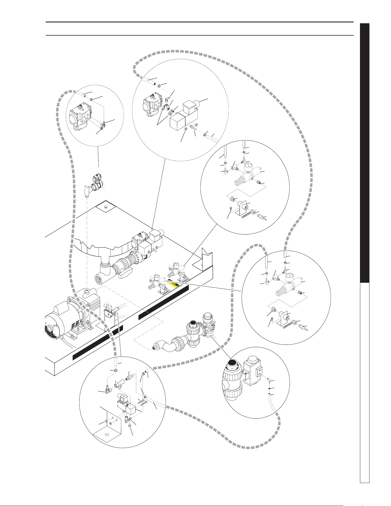
8.914-458.0-G • Water Maze CLB-603
55
WATER TREATMENT SYSTEM
OPERATOR’S MANUAL
CLB-603 AIR COMPONENTS EXPLODED VIEW
89144580-46
1
2
2
2
20
Gemu
Air
Solenoid
Valve
Assy.
Air Valves
Pressure
Regultor
Assy.
Air Stone
Diffuser
Pressure
Regulator
Assy.
Gemu
Air
Solenoid
Valve
Assy.
3
7
12
24
1
13
25
25
25
21
19
14
5
18
14
5
10
6
7
8
11
8
9
4
GF Air
Solenoid
Valve Assy.
Air Solenoid
Bracket
Assy.
24
23
2
1
2
1
6
7
11
8
9
8
10
1
2
22
10
20
17
16
1
1
15
23
3
2
2
13
22
25
4

8.914-458.0-G • Water Maze CLB-603
OPERATOR’S MANUAL WATER TREATMENT SYSTEM
56
CLB-603 AIR COMPONENTS PARTS LIST
ITEM PART NO. DESCRIPTION QTY
1 8.706-958.0 Hose Barb 1/4" Barb x 1/4"
Pipe 90° 7
2 6.390.126.0 Clamp Hose 9
3 8.756-654.0 Valve, Solenoid, Air,
120V, SV16 2
4 9.802-799.0 Screw 1/4" x 1" TEK BLK 4
5 8.707-016.0 Elbow 1/4" NPT x 3/8"
Push-on 2
6 8.707-331.0 Regulator, Air w/Fitter
1/4" Gauge 2
7 8.706-777.0 Nipple, 1/4" Close 3
8 8.706-915.0 Bushing, 1/2"x 1/4" Brass 4
9 8.707-177.0 Nipple 1/4" Male Air 2
10 8.706-854.0 Tee 1/4" Branch Male 3
11 9.802-961.0 Hose Connection Bracket 2
12 8.706-858.0 Tee 1/4" Streel 1
13 8.706-941.0
Hose Barb, 1/4" MT x 1/4"
Hose
2
14 8.709-069.0 Clamp Screw #4 2
15 8.913-164.0 Bracket, Air Solenoid 1
16 8.718-755.0 Screw, 8/32" X 1-1/2",
SS PHIL PH 2
17 8.718-868.0 Nut, 8-32 ESNA, SS 2
18 8.711-733.0 Tubing 3/8" Vinyl 120 in
19 8.711-733.0 Tubing 3/8" Vinyl 12 in
20 9.802-254.0 Hose 1/4" Push-on 9 in
21 9.802-254.0 Hose 1/4" Push-on 12 in
22 9.802-254.0 Hose 1/4" Push-on 19 in
23 9.802-254.0 Hose 1/4" Push-on 31 in
24 9.802-254.0 Hose 1/4" Push-on 34 in
25 8.756-650.0 Muffl er, Exhaust, 1/4"
NPT, Brass 8
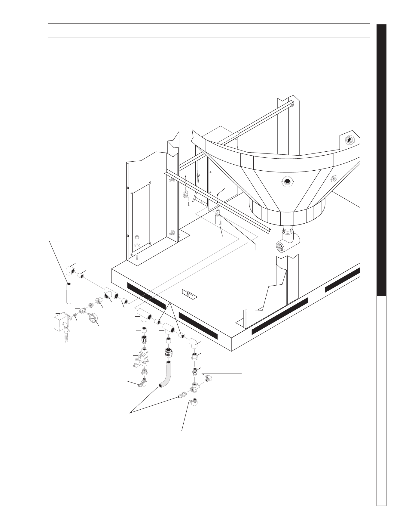
8.914-458.0-G • Water Maze CLB-603
57
WATER TREATMENT SYSTEM
OPERATOR’S MANUAL
89144580-11
To Water
Panel
Assy.
To Transfer
Pump
Assy.
20
21
19
7
5
7
CLB-603 MANIFOLD ASSEMBLY EXPLODED VIEW
To Surge
Tank
Manifold
Mounting
Bracket
To Main
Drain
Assembly
12
13
10
11
9 8
14
16
12
15
12
7
8
7
6
7
5
3
17
18
2
4
1
6
6

8.914-458.0-G • Water Maze CLB-603
OPERATOR’S MANUAL WATER TREATMENT SYSTEM
58
CLB 603 MANIFOLD ASSEMBLY EXPLODED VIEW PARTS LIST
ITEM PART NO. DESCRIPTION QTY
1 8.716-154.0 Switch, Pres Sq. D N/C 1
2 8.706-858.0 Tee, 1/4" Street 1
3 8.712-154.0 Gauge, Pressure 0-100 1
4 8.706-923.0 Bushing, 3/4" x 1/4" Pipe 1
5 8.706-447.0 Adapter, 1", 3/4" S x FIPT,
PVC 80 2
6 8.706-430.0 Tee, 1" S x S, PVC 80 3
7 8.706-366.0 Pipe, 1" PVC 80 (1"x 2") 6
8 8.706-373.0 Elbow, 1" S x S, PVC 80, 90° 2
9 8.706-409.0 Adapter, 1" MT x SLIP, PVC 80 1
10 8.716.-700.0 Solenoid, Valve 120V 1
ITEM PART NO. DESCRIPTION QTY
11 8.706-412.0 Bushing, 1" x 3/4" MT x FT,
PVC 80 1
12 9.803-557.0 Elbow, 3/4" SAE x 3/4"
90° Brass 3
13 8.706-597.0 Union, 1", S x S, PVC 80 1
14 8.706-899.0 Nipple, 3/4" JIC x 3/4" Pipe 1
15 8.706-800.0 Nipple, 3/4" HEX, Brass 1
16 8.706-852.0 Cross, 3/4" Female Pipe 1
17 8.706-777.0 Nipple, 1/4" Brass 1
18 8.716-547.0 Connector, 1/2" Straight 1
19 8.706-422.0 Hanger Pipe, 1 1/4" 2
20 9.802-699.0 Screw 10-32" Slot Pan 2
21 9.802-696.0 Nut 10/32" Keps 2
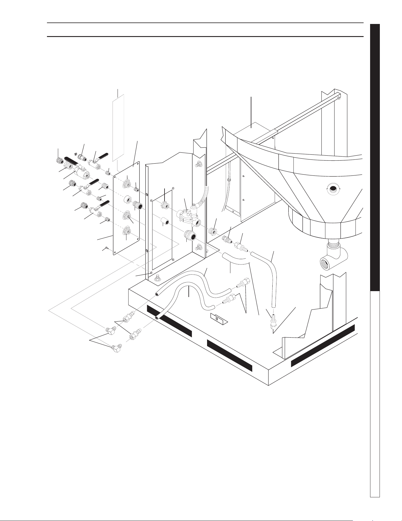
8.914-458.0-G • Water Maze CLB-603
59
WATER TREATMENT SYSTEM
OPERATOR’S MANUAL
89144580-18
11
25
CLB-603 WATER PANEL EXPLODED VIEW
To Ozone
Pump
Assy.
To
Manifold
Assy.
Ozone
Generator
Water
Panel
Assy
3
10
14
17
13
5
2
2
24
1
10
17
4
16
4
15
13
4
13
17
18
20
12
8
7
6
19
9
10
22
23
12
21
12

8.914-458.0-G • Water Maze CLB-603
OPERATOR’S MANUAL WATER TREATMENT SYSTEM
60
CLB-603 WATER PANEL EXPLODED VIEW PARTS LIST
ITEM PART NO. DESCRIPTION QTY
1 8.716-700.0 Solenoid Valve 120V,
HIT 310-100-1 1
2 8.706-412.0 Bushing, 1" x 3/4" MT x FT,
PVC 80 2
3 8.706-899.0 Nipple, 3/4" JIC x 3/4" Pipe 1
4 8.706-968.0 Garden Hose Fitting 3
5 8.706-881.0 Nipple 3/4" pipe 1/2 Pipe 1
6 8.706-597.0 Union, 1" S x S, PVC 80 1
7 8.706-366.0 Pipe, 1" PVC 80 1" x 2" Spacer 1
8 8.706-409.0 Adapter, 1" MT x SLIP,
PVC 80 1
9 9.802-132.0 Elbow, 3/4" JIC x 1/2", 90° 2
10 9.802-152.0 Swivel, 3/4" SAE Fem,
Push-on 6
11 9.802-261.0 Hose, 3/4" Push-on 43 in
ITEM PART NO. DESCRIPTION QTY
12 8.707-000.0 Connector, 1/2" Anchor 3
13 8.706-790.0 Nipple, 1/2" Close 4
14 9.802-146.0 Swivel, 1/2" MP x 3/4" GHF
w/Strainer 1
15 8.706-801.0 Nipple, 1" Close, Brass 1
16 8.707-233.0 Valve, 1" Ball, Brass 1
17 8.707-211.0 Valve, 1/2" 8201 Brass Ball,
400 PSI 3
18 8.913-153.0 Water Panel 1
19 9.802-794.0 Nut Cage, 1/4" x 16 GA 4
20 9.802-765.0 Screw, 1/4-20 X 1/2",
BH Black 4
21 8.901-227.0 Label, Water Maze 1
22 9.802-261.0 Hose, 3/4", Push-on 20 in
23 9.802-261.0 Hose, 3/4", Push-on 30 in
24 8.706-926.0 Bushing, 1" x 1/2", Pipe, Brass 1
25 8.711-812.0 Hose 1" Gray Conduit 26 in
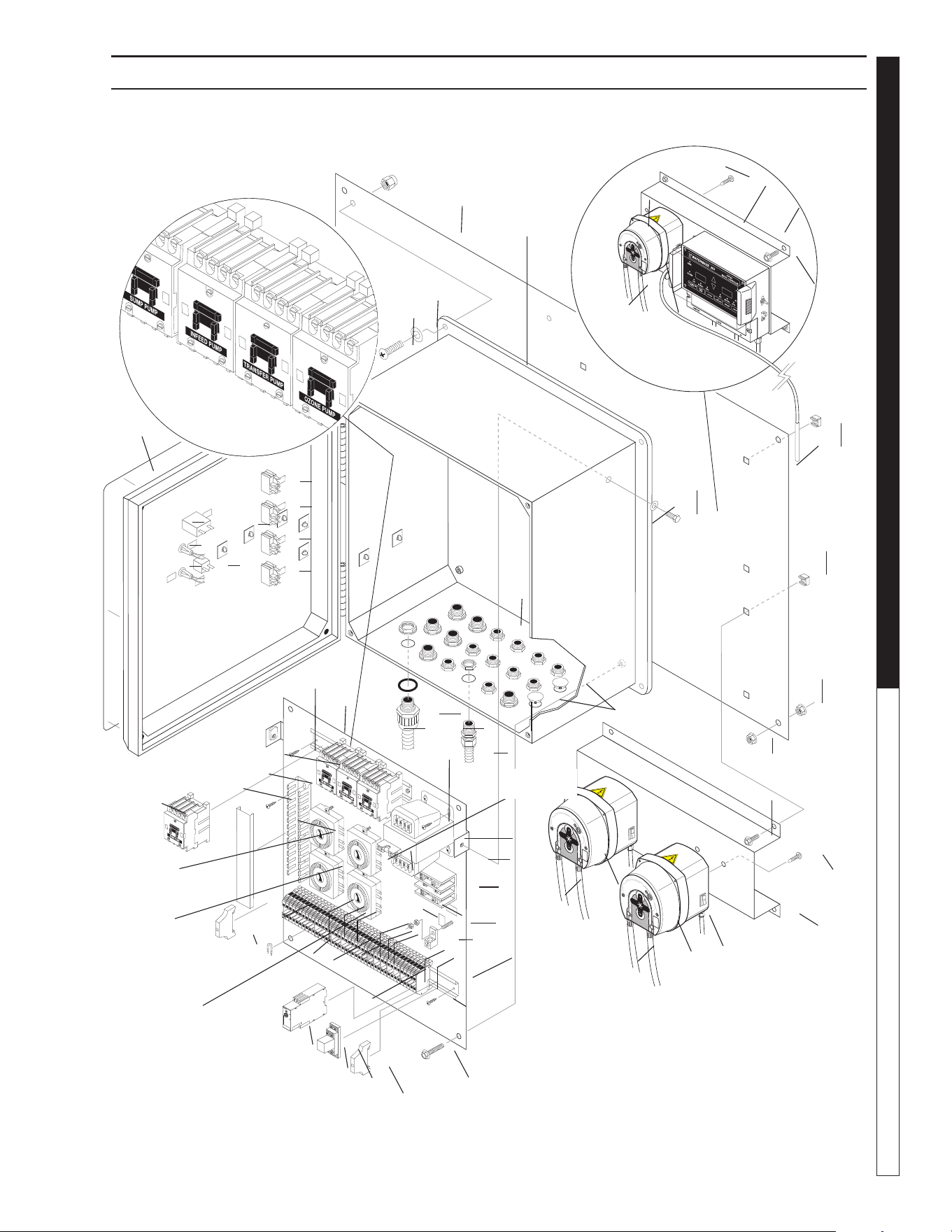
8.914-458.0-G • Water Maze CLB-603
61
WATER TREATMENT SYSTEM
OPERATOR’S MANUAL
89144580-23
41
40
10
36
55
48
56
CLB-603 CONTROL PANEL EXPLODED VIEW
T3 Ozone
Timer
T4
Microbe
Nutrient
Timer
T1 Infeed
Pump Timer
T2 Purge
Timer
pH Controller Assy
(Optional)
Pump
Contactor Detail
37
41
55
38
49
Sensor
32
32
39
42
14
33
47
46
34
30
35
31
31
53 30
54
28
45
45
26
45
11
18
29
15
16
17
20
7
21
22
24
25
12
45
8
19
23
1
1
1
1
6
2
3
5 4
45
51
43
40
55
56
58
50
57
13
20
52
59
27

8.914-458.0-G • Water Maze CLB-603
OPERATOR’S MANUAL WATER TREATMENT SYSTEM
62
ITEM PART NO. DESCRIPTION QTY
1 9.802-451.0 Switch, Rocker, Carling
w/Green Lens 4
2 9.802-283.0 Hour Meter 1
3 9.802-455.0 Light, Indicator, Green 125V 1
4 8.716-091.0 Switch, Momentary Push, 100S
Use w/2-3020 1
5 8.716-409.0 Light, Blue 125V 1
6 8.716-533.0 Clamp, Tie Wrap, Adhesive 21
7 8.724-264.0 Contactor, 120V 4
8 9.803-977.0 Fuse, 2.5 Amp, FNM 2-1/2 1
9 8.901-229.0 ▲ Label, Contactor 1
10 8.716-898.0 Transformer, .150KVA,
230/115V w/Fuse Block 1
11 8.716-253.0 Timer, 24 Hour Pin, 120V 20A 4
12 9.800-040.0 Label, Ground 1
13 8.716-460.0 Terminal, Grounding Lug,
LAMA6-14-Q 1
14 8.716-120.0 Block, Power Distr Adder
GO63130 w/o WLL 1
8.716-121.0 Block, Power Distr 1 Pol
GO63131 1
15 9.802-467.0 Base, Relay, SH2B-05, IDEC 1
16 9.802-468.0 Relay, 120V, RH2B-UL-AC120 1
17 8.751-306.0 Timer, Multi-Function,
24V-120/240V 1
18 9.802-457.0 Din Rail, 35mm 15.5 in.
19 8.716-402.0 Bridge, Entrelec 16897307 21
20 9.804-595.0 End Bracket, Entrelec
103-002-26 2
21 8.716-396.0 Terminal Block, Entrelec
115-116-07 M4/6 33
22 8.716-399.0 End Cover, Entrelec, Gray
11836816 P-On 9
23 8.716-399.0 End Cover, Entrelec
11836816 P-ON 1
24 8.716-398.0 Terminal Block, Blue, Entrelec
125116-01 8
25 9.804-609.0 ▲ Marker, Blank - 6mm,
23300001, NK,
RCG10 100/SH 0.92
26 8.753-351.0 Channel, 1", Gray w/Cover 7 in
27 8.718-568.0 Washer, 1/4" SS
Sealing Rubber 2
28 9.802-457.0 Din Rail, 35mm 9 in
29 9.802-759.0 Screw, 10/32" x 1/2 BHSOC
Blk 4
CLB-603 CONTROL PANEL EXPLODED VIEW PARTS LIST
ITEM PART NO. DESCRIPTION QTY
30 9.802-514.0 Strain Relief, STRT, LQ Tite
3231 Small 28
31 8.716-547.0 Connector, 1/2" Straight, BLK 7
32 9.802-788.0 Nut, 3/56" SS Whiz Loc 12
33 8.716-280.0 Box, Plastic, 18 x 16 x 9.25
w/Hinged Lid 1
34 8.718-621.0 Bolt, 5/16" x 14" NC, HH, SS 4
35 9.802-105.0 Plug, 7/8", Hole 2
36 8.918-076.0 Wlmt, Electrical Standoff CLP 1
37 8.716-989.0 pH Controller w/Sensor
(Option) 1
38 8.913-143.0 Bracket, pH Controller (Option) 1
39 8.913-152.0 Bracket, Microbe/Nutrient Pump 1
40 9.802-765.0 Screw, 1/4" x 1/2" BH SOC CS 4
41 9.802-793.0 Nut, Cage, 1/4" x 16 Ga 8
42 8.749-856.0 Pump, Peristaltic 2
43 8.901-228.0 Label, Water Maze, CLB-603
Control Panel 1
44 8.901-226.0 ▲ Label, Electrical Timers 1
45 8.718-936.0 Screw, # 8 1/2, Phillips 25
46 9.802-805.0 Washer, 5/16" Flat, SAE, SS 4
47 8.913-149.0 Stand Off Plate 1
48 8.749-855.0 Pump, Peristaltic
8-45 gpd (Option) 1
49 8.716-905.0 Sensor, pH (Option) 1
50 8.901-223.0
Label, WaterMaze Nutrient Pump
1
51 9.803-674.0 Screw, 8/32 x 2" 1
52 9.802-785.0 Nut, 8/32 Keps 5
53 9.802-244.0 Conduit, WTR, Tite, Flex 57 in
54 9.802-244.0 Conduit, WTR, Tite, Flex 57 in
55 8.749-857.0 Tubing, Pe Black 1/4" x 4 ft 2
(Option 1/4" x 5 ft) 1
56 8.718-941.0 Screw, 10-16 x 5/8 TEK4
(Option) 2
57 8.901-222.0 Label, Watermaze,
Microbe Pump 1
58 8.900-467.0 Label PH Pump (Option) 1
59 8.718-603.0 Bolt, 1/4" x 3/4" SS 2
▲ Not Shown
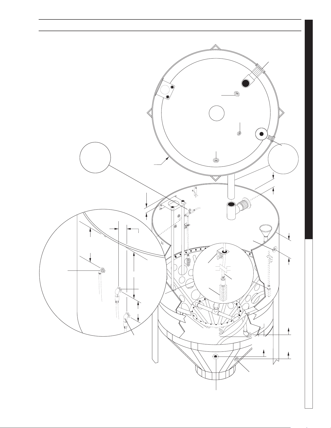
8.914-458.0-G • Water Maze CLB-603
63
WATER TREATMENT SYSTEM
OPERATOR’S MANUAL
89144580-25
CLB-603 DIMENSION LOCATIONS OF TANK CONNECTIONS
1-1/2"
Infeed
Connector
3" Outlet
Connector
1-1/2" Oil
Skimmer
Connector
1-1/2"
Recirculation
Connection
1" Purge
Flush
Connection
Plan View of Tank
8" from
Tank Rim
Oil
Skimmer
Connection
17"
from
Tank
Rim
70" to
Tank
Rim
65" to
Tank
Rim
65" to
Tank Rim
1-1/2" Infeed
Connection
1" Purge
Flush
Connection
1-1/2"
Recirculation
Connection
2-1/2"
9"
12"
5"
Air Stone
Air Line
Microbe
Injection
Nutrient
Injection
Front of
Machine
2" From
Tank Rim
See
Digester
Assy. for Air
Stone Assy.
Air Stone
Air Line
Air Stone
Air Stone
Bracket
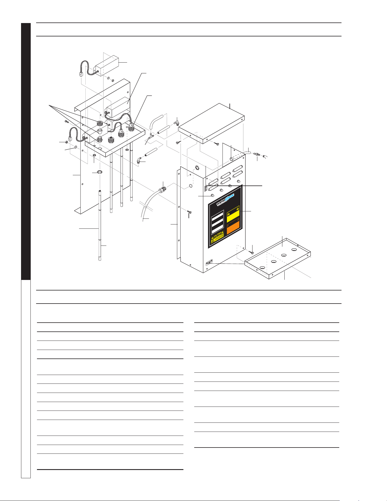
8.914-458.0-G • Water Maze CLB-603
OPERATOR’S MANUAL WATER TREATMENT SYSTEM
64
89144580-13
OZONE GENERAT
OR
DI
S
CONNECT
F
ROM
E
L
E
CT
RI
CAL
S
UPP
L
Y
B
E
F
O
RE
S
E
RVI
CI
NG.
D
E
S
C
ON
E
C
T
E
L
A
C
OR
R
I
E
N
T
E E
L
E
C
T
RI
C
A
AN
T
E
S
D
E
D
A
R
S
E
R
V
I
CI
O
.
C
OU
P
E
R
L
’
A
L
I
M
E
N
T
A
T
I
ON
É
L
E
CT
R
I
Q
UE
A
V
AN
T
D
E
F
A
I
R
E
U
N
E
R
É
P
A
R
A
T
I
ON
.
DI
S
CONNECT
F
ROM
E
L
E
CT
RI
CAL
SUPP
L
Y
B
E
F
O
RE
S
E
R
V
I
CI
NG.
D
E
S
C
ON
E
C
T
E
L
A
C
OR
R
I
E
N
T
E
E
L
E
C
T
RI
C
A
A
N
T
E
S
D
E
D
A
R
S
E
R
V
I
CI
O
.
C
OU
P
ER
L
’
A
L
I
M
E
N
T
A
T
I
O
N
É
L
E
CT
R
I
Q
UE
A
V
AN
T
D
E
FA
I
R
E
U
N
E
R
É
P
A
R
A
T
I
ON
.
INDICATOR L
I
GHT OPERAT
I
O
N
A
b
r
i
g
h
t
c
o
n
t
i
n
u
o
u
s
l
i
g
h
t
i
n
d
i
c
a
t
e
s
UV
l
i
g
h
t
o
r
b
a
l
l
a
s
t
d
e
f
e
c
t
i
v
e.
Un
a
l
u
z
l
u
m
i
n
o
s
a
i
n
d
i
c
a
q
u
e
l
a
l
u
z
u
l
tr
a
-
v
i
o
l
e
t
a
o
t
r
a
n
s
f
o
r
m
a
d
o
r
e
s
tá
d
e
f
e
c
t
u
o
so
.
Un
e
l
u
m
i
è
re
c
l
a
i
re
i
n
d
i
q
u
e
q
u
e
l
a
l
u
m
i
è
re
u
l
t
r
a
v
i
o
l
e
tt
e
o
u
l
e
t
r
a
n
s
f
o
r
m
a
t
e
u
r
e
s
t
d
éfe
c
t
u
e
u
x
.
OPER
A
CIO
N DE LA LUZ
INDICADO
RA
OPÉ
R
A
TIO
N D
E
LE
LAM
PE
INDIC
A
TE
UR
HO
T!
CAL
I
E
N
TE!
C
H
A
U
D
!
C
A
UTION
P
R
E
C
A
U
C
I
O
N
A
TT
E
N
T
ION
8
.
9
0
0
-
4
5
5
.
0
!
W
ARNING!
A
T
ENC
I
O
N
!
/
A
T
T
ENTIO
N
!
!
ITEM PART NO. DESCRIPTION QTY
1 8.913-357.0 Ozone Box, Back, 400 1
2 8.913-360.0 Ozone Box, Front 400 1
3 9.802-455.0 Light, Indicator, Green 4
4 9.802-523.0 Locknut, 3/4" Conduit 4
5 8.716-583.0 Connector, Aluminum Cord
SCH1037 4
6 8.707-355.0 Ozone Check Valve 1
7 8.716-600.0 Lamp, Ozone Replacement 4
8 8.900-455.0 Label, Ozone Generator 1
9 9.802-695.0 Nut, 10/32", NF ST ST KEP 4
10 8.706-570.0 Locknut, 3/8" Nylon 2
11 8.706-585.0 Connector, 3/8" x 3/8",
Male Elbow, Kynar 2
12 8.706-594.0 Tee, 3/8" Kynar 1
13 8.706-733.0 Bushing, 1/2" Snap 1
14 8.711-733.0 Tubing, 3/8" x 1/2",
Black Vinyl 6 ft.
ITEM PART NO. DESCRIPTION QTY
15 9.802-423.0 Cord, Service, SEO, 16/3 8 ft.
16 9.802-453.0 Switch, Curvette, 120V & 220V 1
17 9.802-515.0 Strain Relief, 1/2" NPT
Ozone Gen 1
18 8.706-545.0 Cushion, 1/2", 13-3/4" x 5-3/4",
Rubber 1
19 8.913-358.0 Ozone Box, Top 1
20 8.913-359.0 Ozone Box, Bottom 1
21 8.716-590.0 Ballast, 220V,
Ozone Generator
4
22 9.804-566.0 Screw, 10/32" x 1/2" Slot Pan,
MS ZN 12
23 8.718-968.0 Washer, 10 x SAE ZN 12
24 9.802-798.0 Screw, #10 x 1/2" Tek
Hex Head 8
OZONE GENERATOR EXPLODED VIEW
OZONE GENERATOR EXPLODED VIEW PARTS LIST
Ballast
Ozone Lamp
Prongs
On/Off
Switch
Ozone
Lamp
21
9
23
10
1
4
11
19
12
11
17
13
14
6
16
3
22
8
2
20
18
24
7
15
5
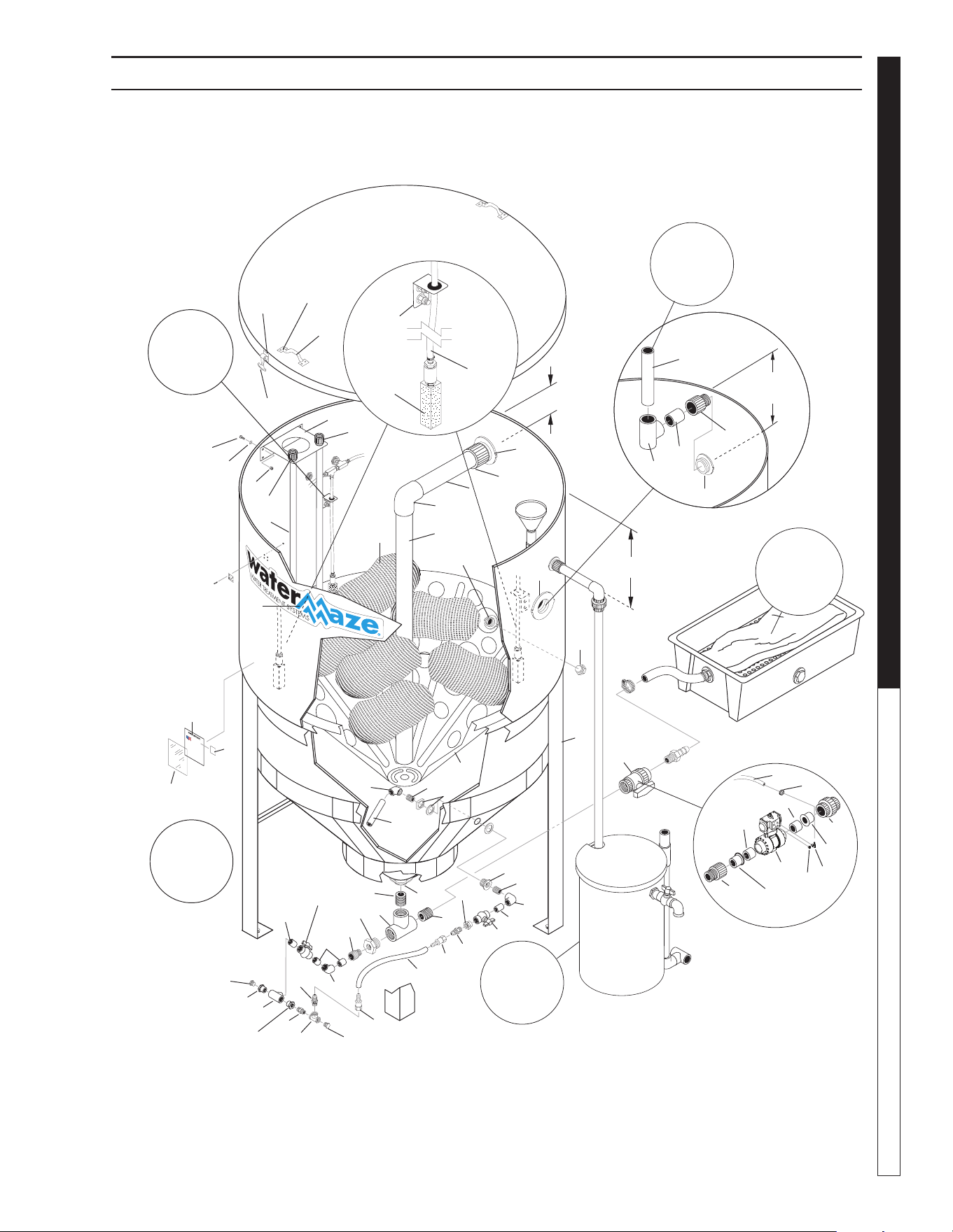
8.914-458.0-G • Water Maze CLB-603
65
WATER TREATMENT SYSTEM
OPERATOR’S MANUAL
89144580-4
Purge
Valve
Assy.
Power In
Customer
Connection
120V 1PH
10"
From
Tank Top
For Detail
See Optional
Oil Skimmer/
Sludge Tub
Illus .
For Detail
See Optional
Oil Skimmer/
Sludge Tub
Illus.
14" From
Tank Top
2
3
30
11
14
Field
Installed
7
12
55
10
63,64
61,62
9
19
20
16
21
17
18
33
39
56
48
51
49
50
6
2
3
4
5
43
2
66
8
32
47
31
47
34
35
36
37
38
28
29
26
23
22
24
65
38
23
37
29
28
48
50
49
47
40
41
67
68
67
44
42
15
15
13
46
45
28
27
25
See
Digester
Assy. for Air
Stone Assy.
Air Stone
Air Line
Air Stone
Air Stone
Bracket
17
CLB-30 AUXILIARY DIGESTER ASSEMBLY EXPLODED VIEW

8.914-458.0-G • Water Maze CLB-603
OPERATOR’S MANUAL WATER TREATMENT SYSTEM
66
ITEM PART NO. DESCRIPTION QTY
1 8.719-177.0 Tank, 600 Gal, Clarifi er, w/Lid 1
2 8.706-483.0 Bulkhead, 3" FT x FT, Polypro 2
3 8.706-454.0 Adapter, 3" SLIP x MT, PVC 40 2
4 8.706-368.0 Pipe, 3" PVC 40 24 in.
5 8.706-385.0 Elbow, 3" SLIP x SLIP, PVC 40 1
6 8.706-368.0 Pipe, 3" PVC 40 36 in
7 8.706-368.0 Pipe, 3" PVC 40 6 in
8 8.913-095.0 Assy, Tank Stand 1
9 8.706-648.0 Handle, Sandpot Lid 2
10 8.706-568.0 Handle, Rubber T, w/Keeper 3
11 8.902-236.0 Cone, 3/16" w/Holes 1
12 8.707-435.0 Bag, Pre-Sewn, Eofi ll 6
8.706-676.0 Plastic, Eofi ll, Bio-System 36 lb
13 8.706-476.0 Union, 2" FS x FT, PVC 80 1
(option)
14 8.706-437.0 Tee, 3" Slip 1
15 8.706-367.0 PIPE, 1.5", PVC 80, /FT
1.5 x 2-3/4 2
16 8.913-157.0 Bracket, Air Stick 1
17 8.706-409.0 Adapter, 1" MT x SLIP, PVC 80 2
18 8.706-366.0 Pipe, 1", PVC 80 1" x 48", 2
19 9.802-721.0 Bolt, 3/8" x 1", HH, SS 10
20 9.802-808.0 Washer, 3/8, SAE SS 10
21 9.802-788.0 Nut, 3/8", Whiz Loc, SS 10
22 8.706-479.0 Bulkhead, 2" NPT, Polypro 1
23 8.706-466.0 Nipple, 2" Close, PVC 80 2
24 8.706-436.0 Tee, 2" FT x FT x FT, PVC 80 1
25 8.706-418.0
Bushing, Reducer, 2 x 1, PVC-80
1
26 8.706-409.0 Adapter, 1" MT x SLIP, PVC 80 1
27 8.706-371.0 Elbow, 1" S x S, PVC 80, 45° 1
28 8.706-366.0 Pipe, 1" PVC 80, 1" x 2" 4
29 8.707-359.0 Valve, 1" S 80 PVC S x S
Molded in Place Ball 2
30 8.706-368.0 Pipe, 3" PVC 40 22 in
(Field Installed)
31 8.706-430.0 Tee, 1" S x S, PVC 80 1
32 8.706-397.0 Plug, 3/4" MT, Sch 80 PVC 1
33 9.800-034.0 Label, Clear Lexan 1
34 8.706-800.0 Nipple, 3/4", Hex, Brass 1
35 8.706-846.0 Tee, 3/4", Female Pipe Brass 1
36 8.706-869.0 Plug, 3/4", Hex, Head 1
37 8.706-899.0 Nipple, 3/4" JIC x 3/4" Pipe 2
38 9.802-152.0 Swivel, 3/4" SAE Fem, Push-on 2
39 9.800-013.0 Label, ASSLD,
USA intended for indoor use 1
40 8.707-349.0 Valve, 2", Single Union Ball 1
41 8.706-451.0 Adapter, 2" Slip x MT, PVC 80
(option) 1
ITEM PART NO. DESCRIPTION QTY
42 8.756-648.0 Valve, Ball, 1-1/2", PNEU ACT,
NO SOL 1
43 8.706-490.0 Bulkhead, 1-1/2" Polypro 1
44 8.706-958.0 Hose Barb, 1/4" Barb x 1/4" Pipe,
90° (option) 1
45 6.390-126.0 Clamp, Hose, .46-.54 ST
(option) 2
46 9.802-254.0 Hose, 1/4" (option) 15 ft
47 8.706-447.0 Adapter, 1", 3/4" S x FIPT,
PVC 80 3
48 8.706-378.0 Elbow, 1" SLIP x FIPT,
PVC 80, 90° 2
49 8.706-439.0 Nipple, 1", PVC 80, Close 2
50 8.706-484.0 Bulkhead, 1" Polypro 1
51 8.706-366.0 Pipe, 1", PVC 80 12 in
52 9.802-486.0 ▲ Wire-nut, Orange
(In Conduit Box) 4
53 8.750-743.0 Bulkhead, 1/2", NPT Polypro 2
54 9.802-517.0 Connector, 1/2", 90° 1
55 8.900-841.0 Label, Water Maze Logo 1
56 ETL Label 1
57 8.716-377.0 ▲ Terminal Ring Tongue 1
58 9.802-696.0 ▲ Nut, 10/32" Kep 3
59 8.718-600.0 ▲ Bolt, 1/4"-20 x 1-1/4 Hex, SS 1
60 9.802-763.0 ▲ Screw, 10/32" x 1 1/4", Slot
(Ground for Junction Box) 1
61 9.802-699.0 Screw, 10/32" 8
62 9.802-696.0 Nut, 10/32" 8
63 9.802-747.0 Screw, 6/32" x 5/16" Round 12
64 8.718-854.0 Nut, 6/32", Keps 12
65 9.802-261.0 Hose, 3/4", Push-on 35 in
66 8.706-394.0 Plug, 11/2", PVC 80 1
67 8.706-413.0 Bushing, 2' X 1 1/2'
Slip, PVC 80 2
68 8.756-650.0 Muffl er, Exhaust, 1/4"
NPT, Brass 1
▲ Not Shown
CLB-30 AUXILIARY DIGESTER ASSEMBLY PARTS LIST
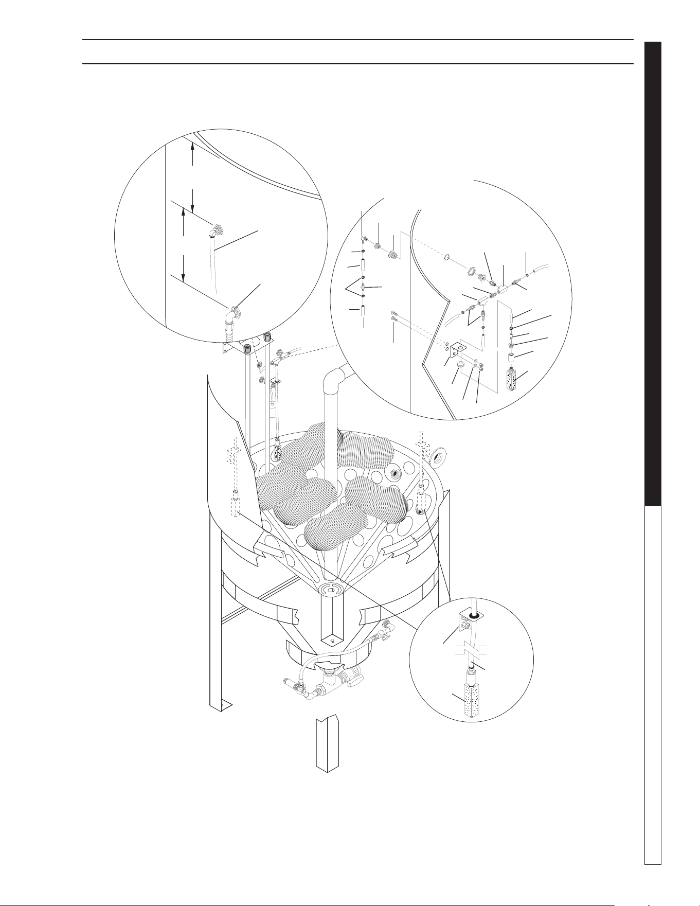
8.914-458.0-G • Water Maze CLB-603
67
WATER TREATMENT SYSTEM
OPERATOR’S MANUAL
89144580-5
Air Stone
Air Line
Air Stick
Float
Switch
CLB-30 AUXILIARY DIGESTER ASSEMBLY EXPLODED VIEW
Connected to
Air Stone Pressure
Regulator
Air
Stone
Assy
10
20
6
7
8
9
3
12
13
9"
11
6
14"
Air Stone
Air Line
Air Stone
Air Stone
Bracket
1
2
2
15
16
17
18
3
14
5
5
19
14
4
11

8.914-458.0-G • Water Maze CLB-603
OPERATOR’S MANUAL WATER TREATMENT SYSTEM
68
ITEM PART NO. DESCRIPTION QTY
1 8.711-733.0 Tubing, 3/8 x 1/2" Clear Vinyl 6 in
2 8.709-069.0 Clamp, Screw #4 3
3 8.706-780.0 Nipple, 1/4" Hex 2
4 9.802-254.0 Hose, 1/4" Push-on 16 in
5 8.706-941.0 Hose Barb, 1/4" x 1/4" MPT 3
6 8.706-407.0 Bushing, 1/2 x 1/4 MT x FT 3
7 8.706-393.0 Coupling, 1/2" SCH 80 3
8 8.712-417.0 Diffuser Stone, Fine Pore,
1/2" NPT 3
9 8.750-743.0 Bulkhead, 1/2" NPT Polypro 1
10 8.707-016.0 Elbow, 90°, 1/4" NPT x 3/8 1
ITEM PART NO. DESCRIPTION QTY
11 6.390-126.0 Clamp, Hose 6
12 8.707-355.0 Check Valve 1
13 8.711-733.0 Tubing 3/8" x 1/2" Clear Vinyl 15 ft
14 8.706-841.0 Tee, 1/4" Female, Pipe 2
15 9.802-064.0 Grommet, Rubber 3
16 9.919-140.0 Bracket, Air Stone 3
17 9.802-805.0 Washer, 5/16" Flat, SAE, SS 6
18 9.802-777.0 Nut, 5/16" ESNA, NC, SS 6
19 8.718-619.0 Bolt, 5/16" x 3/4" NC, GR 5 SS 6
20 8.706-878.0 Nipple, 1/4" Pipe x 1/8" Pipe 3
AUXILIARY DIGESTER ASSY EXPLODED VIEW PARTS LIST
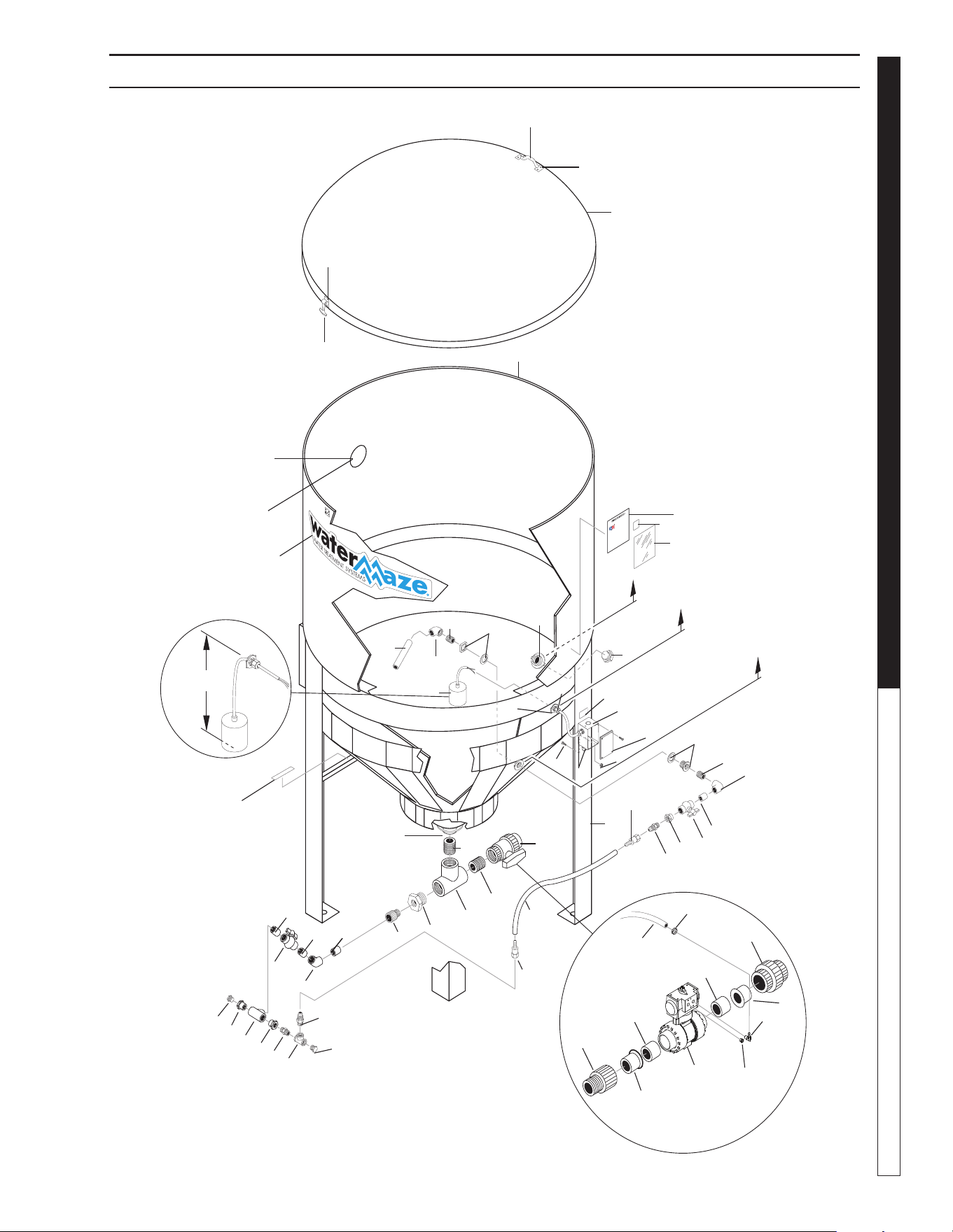
8.914-458.0-G • Water Maze CLB-603
69
WATER TREATMENT SYSTEM
OPERATOR’S MANUAL
89144580-42
7
13
44
42
54" to
Tank Top
5
NOTE: Locate 5" Diameter Hole After Mounting Grass Catcher
NOTE: Only required
when HydroScreen and
HydroScreen bracket
options are ordered.
3
38, 39
40, 41
41
2
Purge
Valve Assy
(Optional)
48" to
Tank Top
36" to
Tank Top
300 Gallon
Tank
Locate 5" Diameter Hole
after Mounting Grass
Catcher
16"
FS1
20
22
43
10
48
46
47
42
13
43
29
25
21
12
30
9
39
6
51
6
31
11
8
52
32
14
15
15
16
18
17
12
12
12
21
19
24
25
23
25
26
27
29
28
33
50
53
53
50
49
34
54
37
36
35
45
30
CLT-300 TANK ASSEMBLY INSTALLATION

8.914-458.0-G • Water Maze CLB-603
OPERATOR’S MANUAL WATER TREATMENT SYSTEM
70
CLT-300 TANK ASSEMBLY PARTS LIST
ITEM PART NO. DESCRIPTION QTY
1 8.719-180.0 Tank, 300 Gal, Clarifi er w/o Lid 1
2 8.719-182.0 Lid, 300 Gal. Clarifi er Tank 1
3 8.706-648.0 Handle, Sandpot Lid 1
4 8.706-568.0 Handle, Rubber T, w/Keeper 3
5 8.716-142.0 Switch, Float, N/O (Black) 1
6 9.802-514.0 Strain Relief, STRT 3
7 8.706-490.0 Bulkhead, 1-1/2" Polypro 1
8 9.802-477.0 Box, Junction 1
9 8.913-142.0 Assy, Tank Stand 300 Gal.,
CLT 300 1
10 8.706-394.0 Plug 1-1/2" PVC 1
11 8.940-186.0 Label Float Switch Junction Box 1
12 8.706-366.0 Pipe, 1" PVC 80 1" x 2" Spacer 4
13 8.706-378.0 Elbow, 1" Slip x FIPT PVC 90 2
14 8.706-479.0 Bulkhead, 2" NPT Polypro 1
15 8.706-466.0 Nipple, 2" Close, PVC 80 2
16 8.706-436.0 Tee, 2" FT x FT x FT, PVC 80 1
17 8.706-418.0 Bushing Reducer, 2 x 1 PVC 80
HT x FT 1
18 8.706-409.0 Adapter, 1" MT x SLIP, PVC 80 1
19 8.706-371.0 Elbow, 1" S x S, PVC 80, 45° 1
20 8.940-221.0 Label Lifting Point 2
21 8.707-359.0 Valve, 1" S 80 PVC, S x S
Molded in Place Ball 2
22 8.900-841.0 Label Water Maze Label, Large 1
23 8.706-430.0 Tee, 1" S x S, PVC 80 1
24 8.706-397.0 Plug, 3/4" MT, SCH 80 PVC 1
ITEM PART NO. DESCRIPTION QTY
25 8.706-447.0 Bushing, 1" x 3/4" SOC x FT
PVC 80 3
26 8.706-800.0 Nipple, 3/4" Hex, Brass 1
27 8.706-846.0 Tee, 3/4" Female Pipe Brass 1
28 8.706-869.0 Plug, 3/4", Hex Head 1
29 8.706-899.0 Nipple, 3/4" JIC x 3/4" Pipe 2
30 9.802-152.0 Swivel, 3/4" SAE Fem,
Push-on 2
31 8.750-743.0 Bulkhead 1/2" Polypro 1
32 8.707-349.0 Valve, 2" Single Union Ball 1
33 8.706-451.0 Adapter, 2" SLIP x MT, PVC 80
(option) 1
34 8.756-648.0 Valve, Ball, 1-1/2", PNEU ACT,
NO SOL 1
35 8.706-958.0 Hose Barb, 1/4" Barb x 1/4" Pipe,
90° (option) 1
36 6.390-126.0 Clamp, Hose, .46-.54 ST 2
37 9.802-254.0 Hose, 1/4" Push-on Fuel Line
(option) 15 ft
38 8.718-760.0 Screw, 10/32" x 5/8" Pan SS 4
39 9.802-696.0 Nut, 10/32 6
40 9.802-747.0 Screw, 6/32 x 5/16 Rnd 12
41 8.718-854.0 Nut, 6/32 Keps 12
42 8.706-439.0 Nipple 1" PVC 80 2
43 8.706-484.0 Bulkhead, 1" Polypro 1
44 8.706-366.0 Pipe, 1" SCH 80 PVC 12 in
45 9.802-261.0 Hose, 3/4 Push-on 24 in
46 9.800-013.0 Label USA Intended Indoor Use 1
47 9.800-034.0 Label Clear Lexan 1
48 9.804-141.0 ETL Label 1
49 8.706-476.0 Union 2" FSX FT PVC 80
(Option) 1
50 8.706-367.0 Pipe, 1.5", PVC 80, /FT
1.5 x 2-3/4 2
51 9.802-699.0 Screw 10-32 x 3/4" Slot Pan 2
52 9.802-478.0 Lid, Plastic Carlon 1
53 8.706-413.0 Bushing, 2' X 1 1/2' SLIP,
PVC 80 2
54 8.756-650.0 Muffl er, Exhaust, 1/4" NPT,
Brass 1
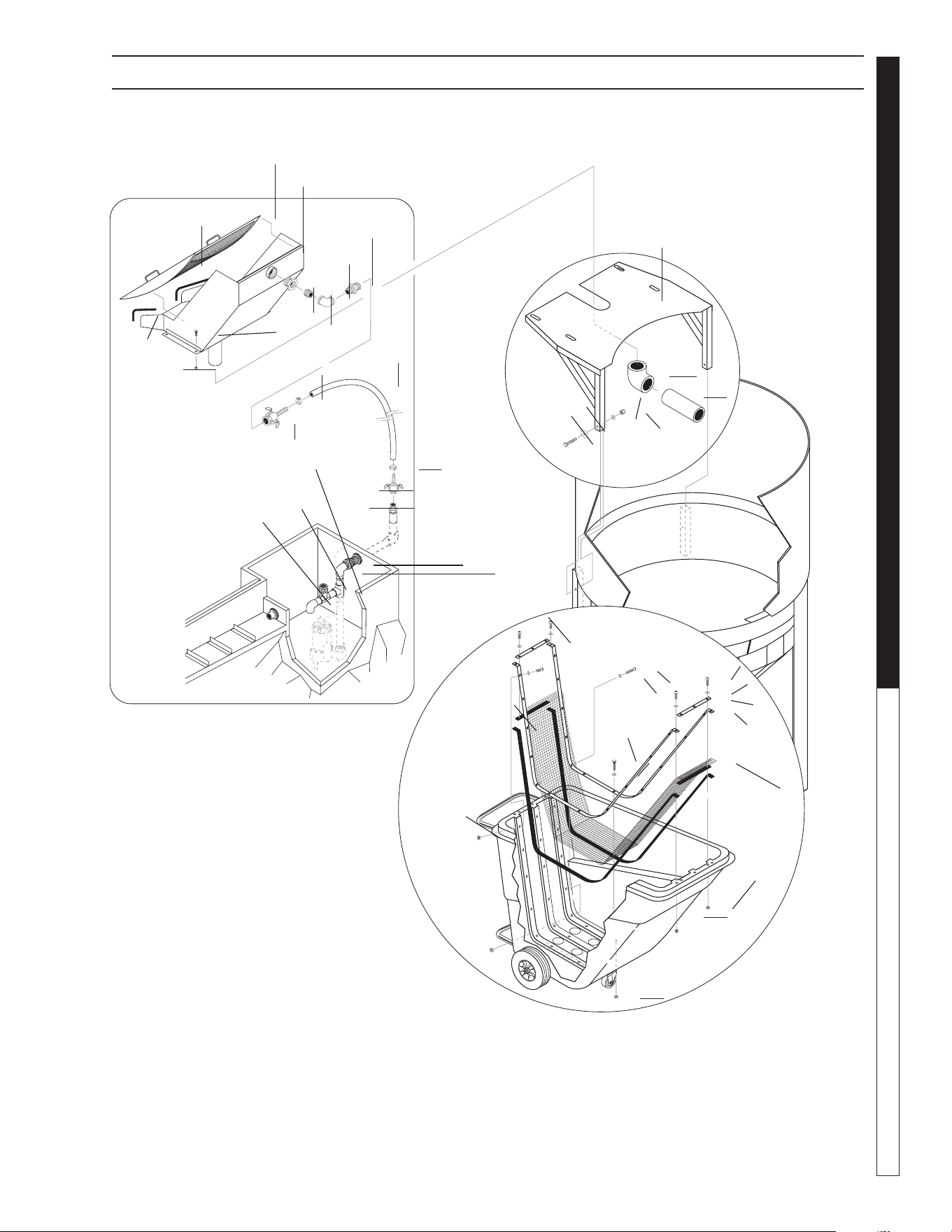
8.914-458.0-G • Water Maze CLB-603
71
WATER TREATMENT SYSTEM
OPERATOR’S MANUAL
CLT-300 TANK ASSEMBLY OPTIONS
89144580-43
Grass Slide
Grass Catcher Assy.
Option #8.903-783.0
Bracket Option
#8.903-784.0
Debris Dumpster
Option #8.903-602.0
1
2
3
4
5
6
7
8
10
11
12
13
14
24
20
21
22
23
25
9
21
6
5
15
15
26
27
28
18
34
32
29
30
17
35
35
31
16
33
34
19
18

8.914-458.0-G • Water Maze CLB-603
OPERATOR’S MANUAL WATER TREATMENT SYSTEM
72
ITEM PART NO. DESCRIPTION QTY
1 8.913-698.0 Assy, Grass Slide, 24" 1
2 8.913-699.0 Grass Screen, 24" 1
3 8.706-424.0 Nipple, 1-1/2" Close, PVC 80 1
4 8.706-375.0 Elbow, 1-1/2" FT x FT, PVC 80
90° 1
5 8.707-169.0 Adapter, 1.5" Male x 1.5" Male
Thrd, CAM 2
6 8.707-168.0 Coupler, 1.5" Fem x 1.5" Hose
Barb, CAM 2
7 8.913-145.0 Bracket, Grass Slide 4
8 9.802-767.0 Screw, 3/8 x 3/4" Whiz Loc 4
9 9.802-071.0 Trim 1/16" Black 3.33 ft
10 9.802-781.0 Nut, 3/8" Whiz Loc 4
11 8.902-229.0 Elbow, 4" SLIP x SLIP,
PVC 40 1
12 8.902-228.0 Pipe, 4" PVC 40 24 in
13 8.706-681.0 Cart Gray Utility 1
14 8.706-403.0 Bushing 2 x 1-1/2" 1
15 8.709-080.0 Clamp, Hose 2
16 8.719-967.0 Screen, 40 Mesh, SS
97" x 17-1/2" 1
17 9.802-193.0 Gasket, Neoprene 18 ft
18 8.706-530.0 Rail, Front End 1.25 x 15" 2
19 8.706-531.0 Rail, Back End, 1.25" x 94" 2
20 8.706-469.0 Union, 1-1/2" Slip 1
21 8.706-374.0 Elbow, 1-1/2", 90°, SLIP 2
22 8.706-426.0 Tee, 1-1/2" SLIP 1
23 8.707-344.0 Valve, 1-1/2" Gate, SLIP 1
24 8.913-698.0 Hose 1-1/2" Gray Sprialite 20 ft
25 9.802-730.0 Bolt 3/8" x 2-1/2 Zinc 2
26 9.802-099.0 Washer Snubbing 2
27 9.802-807.0 Washer Flat 3/8" 2
28 9.802-779.0 Nut 3/8" 2
29 9.802-714.0 Bolt, 5/16" X 1-3/4", NC HH 4
30 9.802-805.0 Washer 5/16" Flat SAE SS 4
31 8.718-887.0 Nut 5/16" SS Whiz Loc 4
32 8.718-754.0 Screw 1/4" - 20 x 1 1/4"
Pan Head SS 4
33 8.718-747.0 Screw 1/4 x 1" SS PH PHIL 24
34 8.718-965.0 Washer 1/4" SS Flat 28
35 8.718-817.0 Nut 1/4-20 Hex Whiz-Loc SS 28
CLT-300 TANK ASSEMBLY OPTIONS PARTS LIST
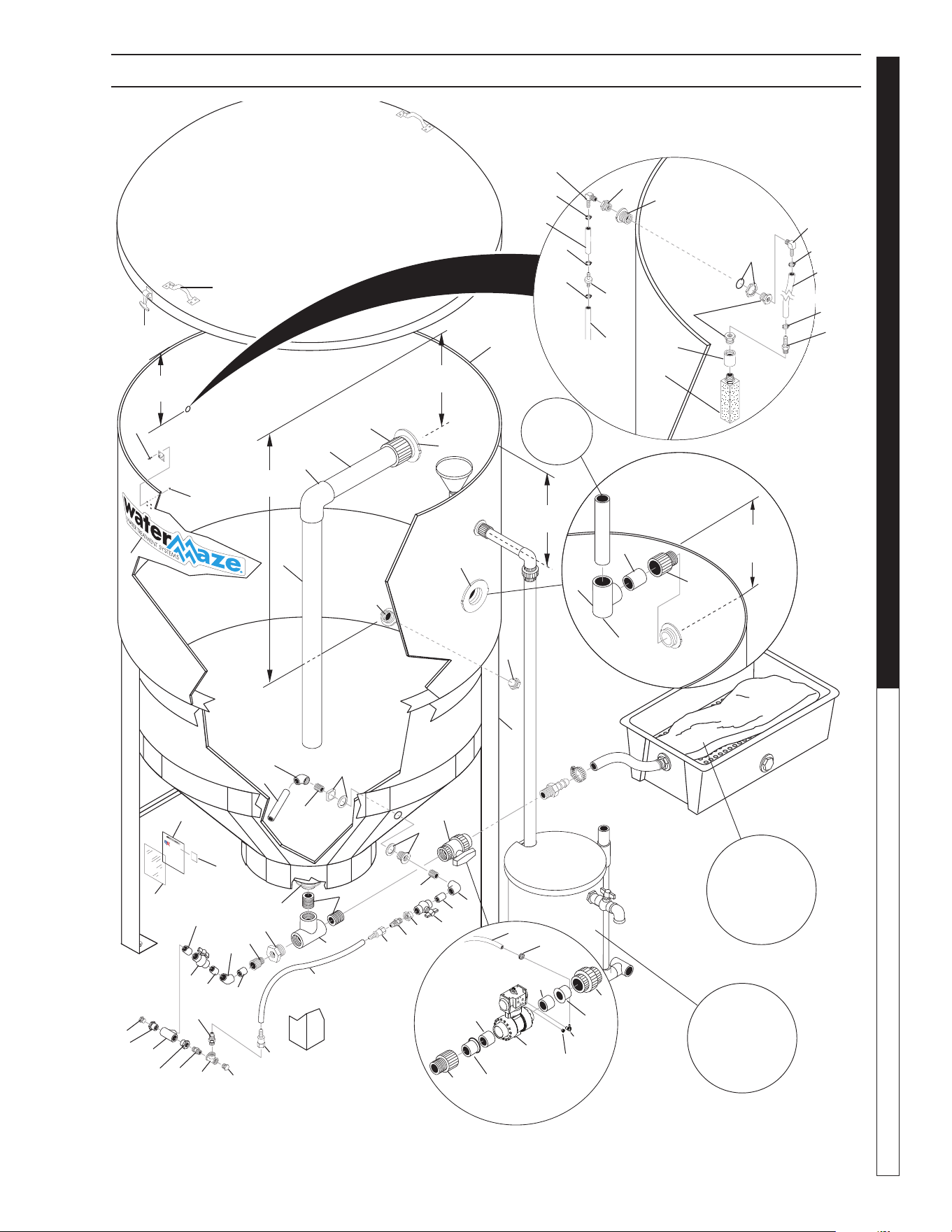
8.914-458.0-G • Water Maze CLB-603
73
WATER TREATMENT SYSTEM
OPERATOR’S MANUAL
89144580-44
Optional Air
Solenoid/Dump
Valve Assy
(Enlarged View)
18" from
Tank Top
48" from
Tank Top
For
Detail See
Optional Oil
Skimmer/
SludgeTub
Illus.
For
Detail See
Optional Oil
Skimmer/
SludgeTub
Illus.
14" from
Top
Connected
to Air Stone
Pressure
Regulator
Air Stone Assy
56
9,10,11
13
48
57
48
48
17" from
Tank Top
Field
Installed
22" from
Tank Top
47
58
54
53
52
55
49
60
50
60
51
26
3
7
63
2
32
8
33
46
41
44
42
43
43
42
41
21
22
40
30
31
36
16
17
15
18
19
20
21
22
21
21
25
40
24
40 27
28
30
29
31
23
45
35
45
34
39
38
37
65
65
66
12
14
6
5
4
3
2
61
64
62
1
59
52
55
Optional Air Solenoid
Dump Valve Assy.
(Enlarged View)
CLT-600 TANK ASSEMBLY EXPLODED VIEW

8.914-458.0-G • Water Maze CLB-603
OPERATOR’S MANUAL WATER TREATMENT SYSTEM
74
CLT-600 TANK ASSEMBLY EXPLODED VIEW PARTS LIST
ITEM PART NO. DESCRIPTION QTY
1 8.719-177.0 Tank, 600 Gal Clarifi er w/Lid 1
2 8.706-483.0 Bulkhead, 3" FT x FT, Polypro 2
3 8.706-454.0 Adapter, 3" SLIP x MT,
PVC 40 2
4 8.706-368.0 Pipe, 3" PVC 40 24 in
5 8.706-385.0 Elbow, 3" SLIP x SLIP,
PVC 40 1
6 8.706-368.0 Pipe, 3" PVC 40 36 in
7 8.706-368.0 Pipe, 3", PVC 40 6 in
8 8.913-095.0 Assy, Tank Stand 600,
Mild Steel 1
9 8.706-648.0 Handle, Sandpot Lid 2
10 9.802-699.0 Screw 10/32 8
11 9.802-696.0 Nut 10/32 8
12 8.706-568.0 Handle, Rubber w/Keeper 3
13 9.802-747.0 Screw, 6/32 x 5/8 12
14 8.718-854.0 Nut, 6/32 12
15 8.706-479.0 Bulkhead, 2" NPT, Polypro 1
16 8.706-466.0 Nipple, 2" Close, PVC 80 2
17 8.706-436.0 Tee, 2" FT x FT x FT, PVC 80 1
18 8.706-418.0 Bushing, Reducer, 2 x 1,
PVC 80 MPT x FPT 1
19 8.706-409.0 Adapter, 1" MT x SLIP,
PVC 80 1
20 8.706-371.0 Elbow, 1" S x S, PVC 80, 45° 1
21 8.706-366.0 Pipe, 1" PVC 80 1" x 2" spacer 4
22 8.707-359.0 Valve, 1" S 80 PVC S x S 2
23 8.706-476.0 Union 2" FS x FT PVC 80
(Option) 1
24 8.706-430.0 Tee, 1" S x S. PVC 80 1
25 8.706-397.0 Plug, 3/4" MT, Sch 80 PVC 1
26 8.706-437.0 Tee, 3" S x S x S 1
27 8.706-800.0 Nipple, 3/4" Hex, Brass 1
28 8.706-846.0 Tee, 3/4" Female Pipe Brass 1
29 8.706-869.0 Plug, 3/4" Hex, Head 1
30 8.706-899.0 Nipple, 3/4" JIC x 3/4" Pipe 2
31 9.802-152.0 Swivel, 3/4" SAE Fem,
Push-on 2
32 8.706-394.0 Plug, 1 1/2" PVC 80 1
ITEM PART NO. DESCRIPTION QTY
33 8.707-349.0 Valve, 2" Single Union Ball 1
34 8.706-451.0 Adapter, 2" SLIP x MT,
PVC 80 (Option) 1
35 8.756-648.0 Valve, BalL, 1-1/2", PNEU ACT,
NO SOL 1
36 9.802-261.0 Hose, 3/4" Push-on 35 in
37 8.706-958.0 Hose Barb, 1/4" Barb x 1/4"
Pipe, 90° (Option) 1
38 6.390-126.0 Clamp, Hose, .46-.54 ST
(Option) 2
39 9.802-254.0 Hose, 1/4" Push-on,
Fuel Line 15 ft
(Option)
40 8.706-447.0 Adapter, 1", 3/4" S x FIPT
PVC 80 3
41 8.706-378.0 Elbow, 1" SLIP x FIPT
PVC 80, 90° 2
42 8.706-439.0 Nipple, 1", PVC 80, Close 2
43 8.706-484.0 Bulkhead, 1" Polypro 1
44 8.706-366.0 Pipe, 1" PVC 80 12 in
45 8.706-367.0 Pipe, 1.5", PVC 80, /FT
1.5 x 2-3/4 2
46 8.706-490.0 Bulkhead, 1-1/2" Polypro 1
47 8.711-733.0 Tubing, 3/8 x 1/2"
Clear Vinyl 15 ft.
48 8.709-069.0 Clamp, Screw #4 3
49 8.706-958.0 Hose Barb, 1/4 Barb x 1/4 Pipe 1
50 9.802-254.0 Hose, 1/4" Push-on 16 in.
51 8.706-941.0 Hose Barb, 1/4" x 1/4" Pipe 1
52 8.706-407.0 Bushing, 1/2 x 1/4 MT x FT 3
53 8.706-393.0 Coupling, 1/2" SCH 80 1
54 8.712-417.0 Diffuser Stone, Fine Pore,
1/2" NPT 1
55 8.750-743.0 Bulkhead, 1/2" NPT Polypro 1
56 8.707-016.0 Elbow, 90°, 1/4" NPT x 3/8 1
57 8.711-733.0 Tubing, 3/8 x 1/2" Clear Vinyl 6 in
58 8.707-355.0 Check Valve 1
59 8.900-841.0 Label WaterMaze Logo Large 1
60 6.390-126.0 Clamp Hose 2
61 9.800-013.0 Label USA Intended Indoor use 1
62 9.800-034.0 Label, Clear Lexan 1
63 8.706-638.0 Pipe 3" PVC 40 22 in
64 9.804-141.0 ETL Label 1
65 8.706-413.0 Bushing, 2' X 1 1/2' SLIP,
PVC 80 2
66 8.756-650.0 Muffl er, Exhaust, 1/4" NPT,
Brass 1

8.914-458.0-G • Water Maze CLB-603
75
WATER TREATMENT SYSTEM
OPERATOR’S MANUAL
89144580-12
OIL SKIMMER & SLUDGE TUB ASSEMBLY EXPLODED VIEW
To Main
Tank
Bottom
Cone
Oil
Collection
Funnel
Bulkhead
Through
Coalescing
Tank
Oil Collection
Barrel
1
2
3
4
4
12
14
10
19
23
21
12
24
26
15
26
26
15
11
20
26
13
21
16
17
22
18
13
9
14
14
Sludge Tub Assembly
Oil Skimmer Assembly
7
6
5
8
5
6

8.914-458.0-G • Water Maze CLB-603
OPERATOR’S MANUAL WATER TREATMENT SYSTEM
76
OIL SKIMMER & SLUDGE TUB ASSEMBLY PARTS LIST
ITEM PART NO. DESCRIPTION QTY
1 8.719-179.0 Tub, Sludge, w/Lid (Black) 1
2 8.913-094.0 Support, Sludge Bag 1
3 8.719-191.0 Bag, Sludge, Qty 1,
Biodegradable 5
4 8.706-479.0 Bulkhead, 2" NPT Poly 2
5 8.706-453.0 Adapter 2" MTx 2- M
Hose Insert 5
6 8.709-083.0 Clamp, 3 -1/2" SS Band 5
7 8.711-817.0 Hose 2" Clear Spiralite 21 in
8 8.711-817.0 Hose 2" Clear Spiralite 84 in
9 8.707-361.0 Valve 1 1/2" 80 PVC S x S 1
10 8.706-683.0 Funnel, Plastic Oil Skimmer 1
11 8.706-374.0 Elbow, 1.5" S x S 1
12 8.706-372.0 Elbow, 1-1/2" S x T 2
13 8.706-468.0 Nipple, 1-1/2" x 3" 1
14 8.706-490.0 Bulkhead, 1-1/2" Polypro 3
15 8.706-469.0 Union, 1-1/2" S x S 2
16 8.706-367.0 Pipe, 1-1/2" PVC 80 57 in
17 8.706-428.0 Tee, 1-1/2", S x S x T 1
18 8.719-169.0 Tank, Vertical w/Lid, 26 Gallon 1
19 8.706-492.0 Nipple, 1-1/2" x 2-1/2" 1
20 8.706-441.0 Adapter, 1.5" S x MT 1
21 8.706-424.0 Nipple 1.5 x Close PVC 80 2
22 8.706-482.0 Nipple 11/2" x 6" PVC 80 1
23 8.706-375.0 Elbow 11/2" FTx FT PVC 80 1
24 8.706-367.0 Pipe 1.5 PVC 80 14 in
25 8.706-367.0 Pipe 1.5 PVC 80 11 in
26 8.706-367.0 Pipe 1.5 PVC 80 1.5 x 21/2" 4
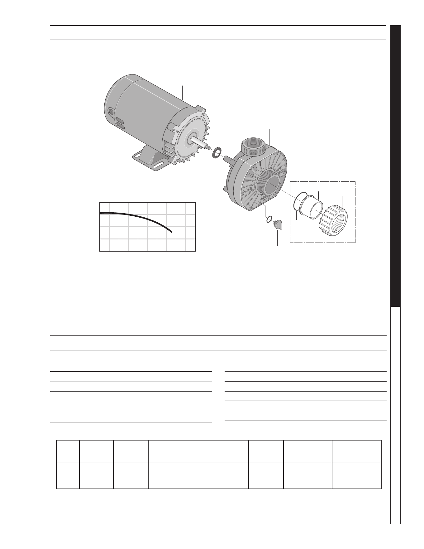
8.914-458.0-G • Water Maze CLB-603
77
WATER TREATMENT SYSTEM
OPERATOR’S MANUAL
OZONE PUMP EXPLODED VIEW
ITEM PART NO. DESCRIPTION QTY
1 8.726-026.0 Motor, 3/4 HP, 230V 1
2 NA Slinger 1
3 8.726-024.0 Pump, 3/4 HP, Wet End 1
4 NA Drain Plug 1
5 NA O-Ring, Drain Plug 1
HP Volts Phase
Size
Inlet Outlet
Running
Amps
Max.
Pressure
Max.
Water Temp.
3/4 230V 1 1-1/2" FPT/ 1-1/2"FPT/
1-1/2" MBT 1-1/2" MBT
5.7 40 PSI 104°F/40°
ITEM PART NO. DESCRIPTION QTY
6 NA O-Ring 1
7 NA Adapter, Union 1-1/2” Slip 1
8 NA Collar, Union 1
Kit:
6-8 8.750-270.0 Fitting, Compression, 1-1/2" Slip
Part # 8.917-760.0
OZONE PUMP EXPLODED VIEW PARTS LIST
40
20
0
20 40 60 80
U.S. GALLONS PER MINUTE
TOTAL HEAD IN FEET
1
2
3
4
5
6
7
8
Not Included
With Pump
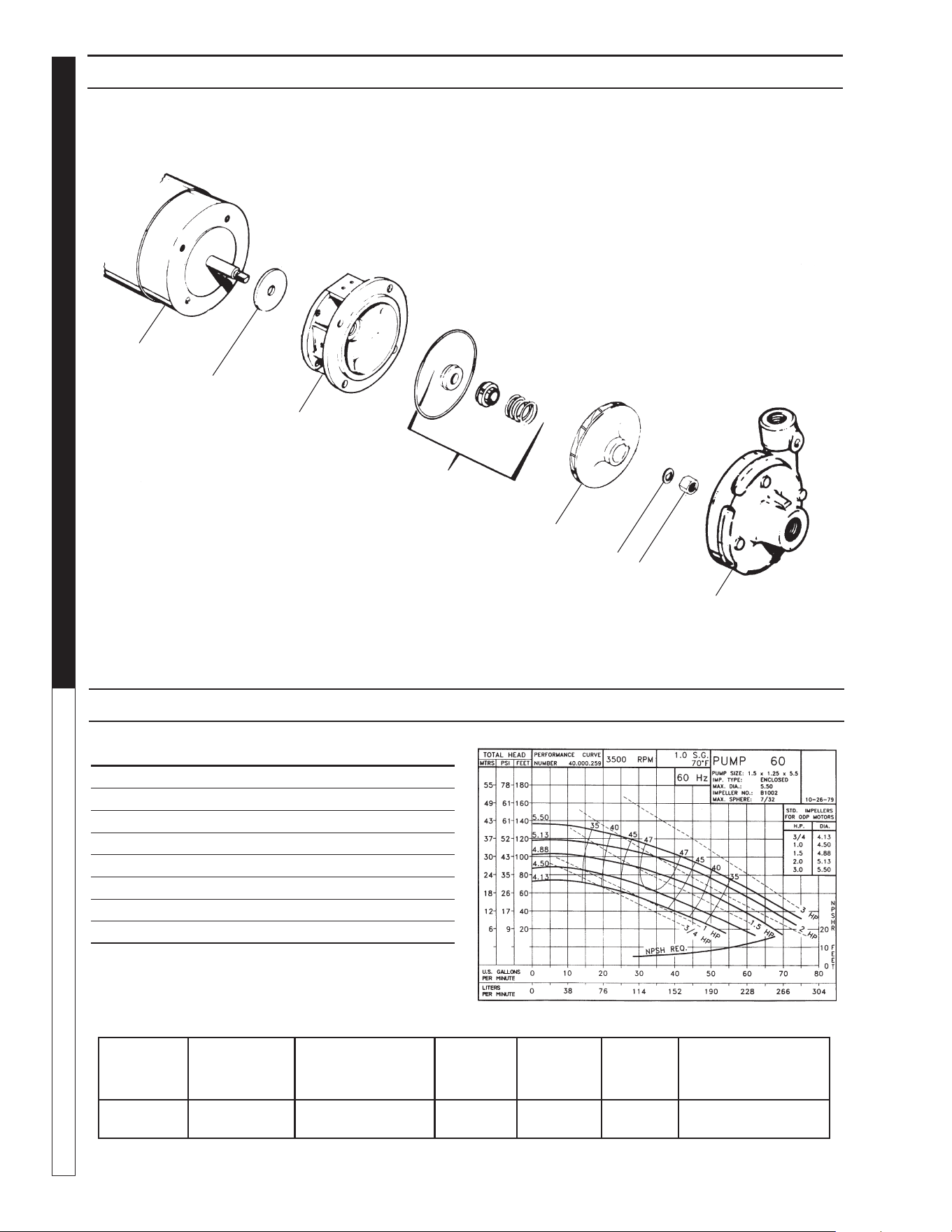
8.914-458.0-G • Water Maze CLB-603
OPERATOR’S MANUAL WATER TREATMENT SYSTEM
78
OPTIONAL TRANSFER PUMP EXPLODED VIEW
8.715-402.0, 2 HP, 230V 1 PH
ITEM PART NO. DESCRIPTION QTY
1 8.718-520.0 Flinger 1
2 88-132000200 Adapter 1
3 88-118000340G Seal 1
4 8.718-534.0 5.13" Impeller 1
5 88-104000168 Washer 1
6 8.718-521.0 Nut 1
7 88-130000170 Case 1
8 88-113000348 Motor, 2 HP 230V 1 PH 1
OPTIONAL TRANSFER PUMP EXPLODED VIEW PARTS LIST
BRAND MODEL NO.
SIZE
INLET OUT-
LET AMPS VOLTS PHASE MAXGPM, PSI
SCOT 60 1-1/2" 1-1/4" 9.1 230 1 See Chart Above
1
2
3
4
5
6
7
8
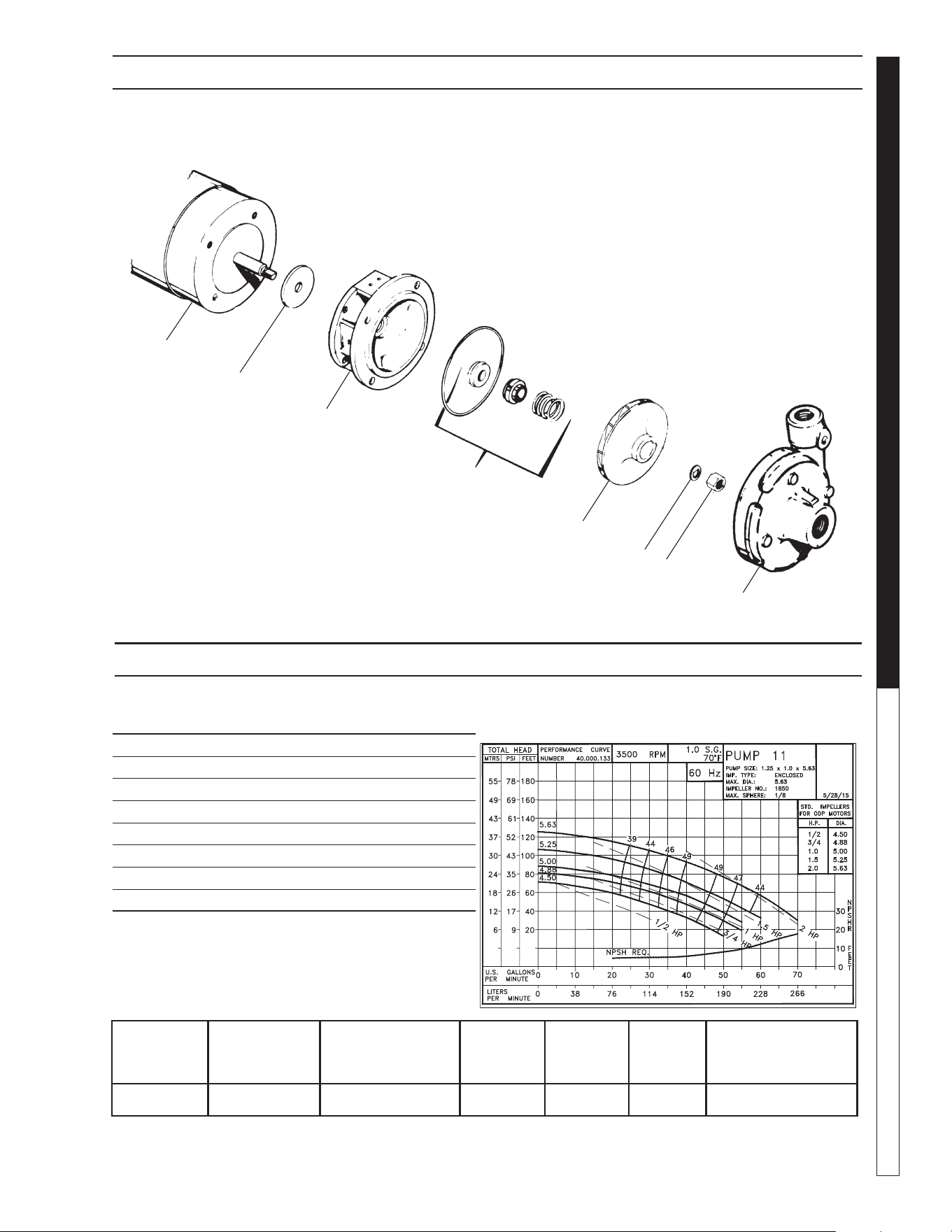
8.914-458.0-G • Water Maze CLB-603
79
WATER TREATMENT SYSTEM
OPERATOR’S MANUAL
TRANSFER PUMP EXPLODED VIEW
#8.755-986.0 3/4 HP 1PH
ITEM PART NO. DESCRIPTION QTY
1 104.000.171 Flinger 1
2 132.000.337X Adapter 1
3 101.000.239 Seal VN-SIL/SIL 1
4 131.000.763D 4.88" Impeller 1
5 104.000.168 Washer 1
6 105.000.465 Nut 1
7 137.002.664X Case 1
8 Motor, 3/4 HP 230V 1 PH 1
1
2
3
4
5
6
7
8
TRANSFER PUMP EXPLODED VIEW PARTS LIST
BRAND MODEL NO.
SIZE
INLET OUT-
LET AMPS VOLTS PHASE MAXGPM, PSI
SCOT 11 1-1/4" 1" 5.5 230 1 See Chart Above
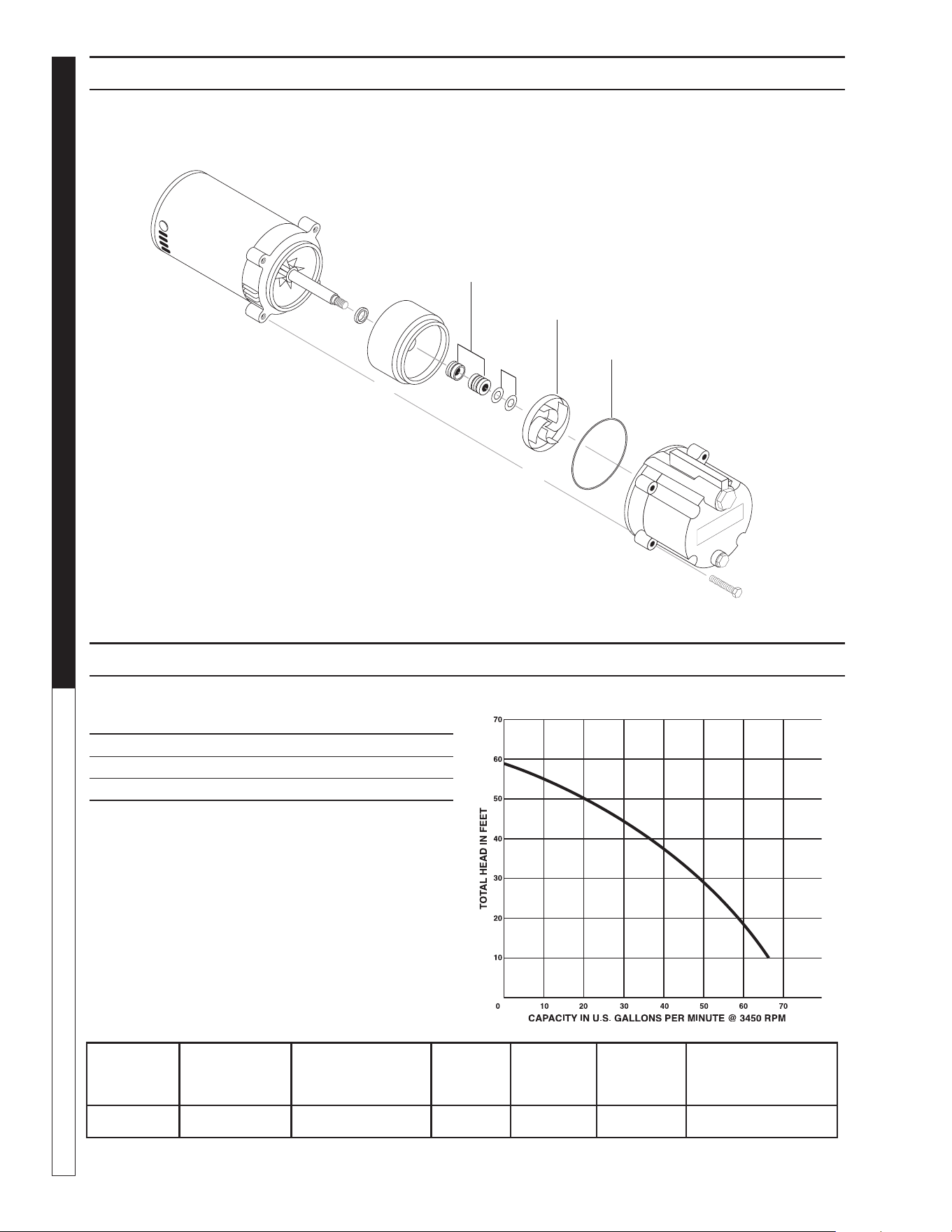
8.914-458.0-G • Water Maze CLB-603
OPERATOR’S MANUAL WATER TREATMENT SYSTEM
80
INFEED PUMP PUMP EXPLODED VIEW
INFEED PUMP PUMP EXPLODED VIEW PARTS LIST
ITEM PART NO. DESCRIPTION QTY
1 8.749-983.0 Seal 1
2 8.749-984.0 Impeller 1
3 8.725-503.0 O-Ring 1
89144580-29
1
2
3
#8.715-387.0 1/2 HP 1 PH
BRAND MODEL NO.
SIZE
INLET OUT-
LET AMPS VOLTS PHASE FLOW/HEAD
AMT 2852-95 1-1/4" 1-1/4" 4.0 230 1 See Chart Above


Form CLB-603 #8.914-458.0 • Printed in U.S.A.