OPERATOR’S MANUAL
For technical assistance or the Water Maze Dealer consult our web page at
www.wmaze.com
09/30/16
8-913-971.0-A
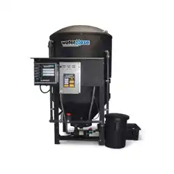
■ CL-30
CLARIFIER

CONTENTS
2
Watermaze CL-30 • 8.913-971.0 - A
Model Number ______________________________
Serial Number ______________________________
Date of Purchase ____________________________
The model and serial numbers will be found on a decal attached
to the Water Maze or machine. You should record both serial
number and date of purchase and keep in a safe place for future
reference.
Introduction .................................................................................................................................... 3
Unpacking ...................................................................................................................................... 3
Safety Instructions ......................................................................................................................3-4
Installation Instructions ............................................................................................................... 4,6
CL-30 Installation View and Component Identifi cation .................................................................. 5
Operating Procedure ..................................................................................................................... 6
Electrical Instructions ..................................................................................................................... 6
Start-up Check List ........................................................................................................................ 6
Start-up Procedures ...................................................................................................................... 6
General Maintenance and Service ................................................................................................7
Chemical Maintenance Program ................................................................................................ 7-8
Daily Chemical Maintenance ......................................................................................................... 8
Sump Pump Maintenance ............................................................................................................. 9
CL-30 Breakdown #1 and Parts List ....................................................................................... 10-11
CL-30 Breakdown #2 and Parts List ....................................................................................... 12-13
CL-30 Breakdown #3 and Parts List ....................................................................................... 14-15
CL-30 Control Panel and Parts List ........................................................................................16-17
Submersible Sump Pump #8.715-368.0, #8.715-438.0,, #8.715-439.0, and Parts List ........18-19
Troubleshooting - Pump ............................................................................................................... 20
Troubleshooting - Clarifi er ............................................................................................................ 21
Specifi cations ............................................................................................................................... 22
Warranty ...................................................................................................................................... 23
CLARIFIER 30 OPERATOR’S MANUAL
3
Watermaze CL-30 • 8.913-971.0 - A
INTRODUCTION
This machine was not designed as a stand alone product.
It was designed to be connected to a WATER MAZE
Delta, CLP or Clarifi er 600 Series. This manual covers
only limited information and specifi cs may vary from
installation to installation.
Your owner’s manual has been prepared to provide
you with a simple and understandable guide to equip-
ment operation and maintenance, based on the latest
product information available at the time of printing. To
keep your machine in top running condition, follow the
specifi c maintenance and troubleshooting procedures
given in this manual.
Owner/User Responsibility:
The owner and/or user must have an understanding
of the manufacturer’s operating instructions and warn-
ings before using this WATER MAZE machine. Warning
information should be emphasized and understood. If
the operator is not fl uent in English, the manufacturer’s
instructions and warnings shall be read to and discussed
with the operator in the operator’s native language by
the purchaser/owner, making sure that the operator
comprehends its contents.
The owner and/or user must study and maintain the
manufacturer’s instructions for future reference.
NOTE: WATER MAZE reserves the right to make
changes at anytime without incurring any obligations.
SAVE THESE INSTRUCTIONS
This manual should be considered a permanent
part of the machine and should remain with it if
machine is resold.
When ordering parts, please specify model and se-
rial number. Use only identical replacement parts.
This machine is to be used only by trained opera-
tors.
UNPACKING
1. 165 gallon water tank
2. Coalescing cone assembly
3. Sump pump assembly
4. Oil water separation barrel
5. Waste collection bag and pan
6. Exterior plumbing
7. Operator’s manual
NOTE any damage to machine or components for claims
against the freight lines.
SAFETY INSTRUCTIONS
1. Read the owner’s manual thoroughly. Failure to fol-
low instructions could cause a malfunction of the
machine and result in death, serious injury and/or
property damage.
CAUTION: To reduce the risk of
injury, read operating instruc-
tions carefully before using.
WARNING: Ground system before
connecting to the power supply.
WARNING: Wire the system for
correct voltage. See “Electrical”
section of this manual and motor
nameplate.
WARNING: Meet National Electri-
cal Code and local codes for all
wiring.
WARNING: Follow the wiring in-
structions in this manual when
connecting the system to the
power lines.
WARNING: All wiring must be per-
formed by a qualifi ed electrician.
2. When connecting to the power supply, follow all elec-
trical and safety codes, as well as the most recent
National Electric Code (NEC) and the Occupational
Safety and Health Act (OSHA).
3. This machine, when installed, must be electrically
grounded in accordance with local and/or national
codes. Do not spray water near any electrical com-
ponents.
4. Never make adjustments on this machine while it
is in operation, except for those prescribed in this
manual.
5. Do not discharge gasoline or other volatile hydrocar-
bons into the Clarifi er. This could cause a gas vapor
buildup inside the Clarifi er which could become an
explosive mixture.
6. Before servicing, refer to all the MSDS’s on the mate-
rial identifi ed in the waste stream. You must comply
with all warnings and wear all protective clothing as
stated on the MSDS’s.
7. Protect inlet and outlet pipes from vehicle traffi c and
sharp objects.
8. Inlet water temperature must not exceed 85° F.
9. The best insurance against an accident is precaution
and knowledge of the equipment.
WARNING
HAZARDOUS VOLTAGE
CAN SHOCK, BURN
OR CAUSE DEATH.
GROUND SYSTEM BE-
FORE CONNECTING TO
POWER SUPPLY.
CAUTION
READ OPERATOR'S
MANUAL THOROUGHLY
PRIOR TO USE.

4
CLARIFIER 30 OPERATOR’S MANUAL
Watermaze CL-30 • 8.913-971.0 - A
10. WATER MAZE is not liable for modifi cations or for
components that are not purchased from WATER
MAZE.
11. In cold climates, locate this machine in a heated
enclosure.
12. Running the system without water will damage the
pumps and will void the warranty.
13. Know the system application, limitations and poten-
tial hazards.
WARNING: Do not use concentra-
tions of fl ammable or explosive
fl uids such as gasoline, fuel oil,
kerosene, etc. Do not use in ex-
plosive atmospheres. The Clari-
fi er should only be used with liq-
uids compatible with component
materials. Failure to follow this
warning can result in personal
injury and/or property damage.
14. Make certain that the power source conforms to the
Clarifi er electrical requirements. Check serial plate
for proper voltage and amperage requirements.
15. Disconnect the power before servicing.
16. Release all pressure within the system before servic-
ing any component.
17. Drain all liquids from the components before servic-
ing.
18. Check hoses for weak or worn condition before
each use, making certain that all connections are
secure.
19. Periodically inspect pump and system components.
Perform routine maintenance as required.
20. Personal Safety:
a. CAUTION: Wear safety glasses and other ap-
plicable protective clothing at all times when
working on the Clarifi er. NOTE: Refer to item
#6 under Safety Instructions.
b. Keep your work area clean, uncluttered and
properly lighted. Replace all unused tools and
equipment.
c. Keep visitors at a safe distance from the work
area.
d. Make the workshop safe with padlocks and
master switches.
21. All wiring should be preformed by a qualified
electrician.
22. Protect all electrical cords from sharp objects, hot
surfaces, oil, sunlight and chemicals. Avoid kink-
ing the cords. Replace or repair damaged or worn
cords immediately. All wiring should be run through
conduit.
NOTE: The sump pump is not a trash pump and is
subject to premature failure unless sump baffl ing or ad-
ditional protection is provided.
INSTALLATION INSTRUCTIONS
1. Locate the Clarifi er on a containment pad to prevent
contamination.
2. Level the machine by using shims that will provide
ample support and will not corrode or deteriorate
over time.
3. On three phase machines, have a qualifi ed electri-
cian connect the proper power supply to the electri-
cal control box. It is recommended that a ground fault
circuit interrupter be installed in the circuit breaker
for the Clarifi er.
NOTE: An electrician needs to locate where the
power supply will enter the electrical box and punch
a hole.
4. Build oil decanter barrel.
5. Connect the sludge tub assembly by placing the
sludge bag support into the sludge tub. Attach the
sludge bag onto the sludge inlet fi tting using the
screw clamp provided.
6. Attach the 2" fl ex hose to the sludge tub by screw-
ing the hose barbs into the bulkhead connectors,
then attach the 2" fl ex hose to the hose barb using
a hose clamp. The return line should gravity return
to the catch basin or connect to the return line. The
2" inlet fl ex hose should connect between the cone
tank discharge valve and the sludge bag inlet con-
nector.
7. On the three phase units only, run the electrical cords
from the pump and fl oat to the electrical boxes near
the inlet line and attach wires. If the sump pump and
fl oat is located farther then 20 feet from the electrical
junction boxes, then have an electrician install water
tight junction boxes with conduit and proper sized
wire to extend the electrical connections.
8. Run the "Return/Backwash" line (refer to page 5)
back to the collection pit or fi rst pit where the water
will be collected. Run at least a 2" line if above
ground and 3" if below ground. The sludge tub and
oil decanter barrel are plumbed together and run to
the return line. Any back pressure could overfl ow
the sludge tub and/or oil decanter barrel. A separate
return line for the sludge tub and oil decanter barrel
may be needed or the sludge tub can be elevated.
9. Tefl on tape the 2" close nipples. Thread the 2" close
nipples into the bulkheads by hand.
WARNING
RISK OF EXPLOSION:
DO NOT SPRAY
FLAMMABLE
LIQUIDS.
CLARIFIER 30 OPERATOR’S MANUAL
5
Watermaze CL-30 • 8.913-971.0 - A
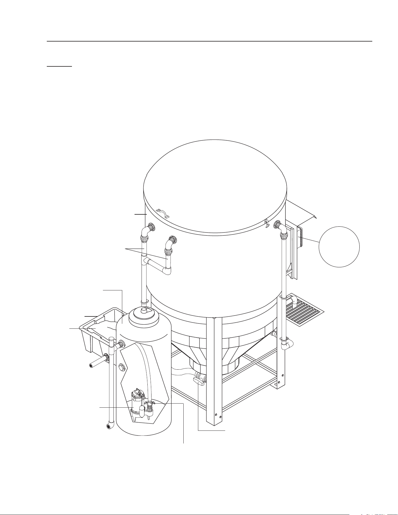
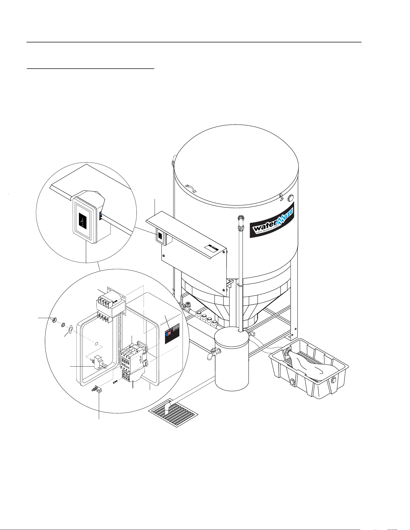
CL-30
INSTALLATION VIEW/COMPONENT IDENTIFICATION
Sump Pit
165 Gal. Vertical
Storage Tank
Return Line
To Furthest Pit
Sump Pump
Outlet To Main
Clarifi er System
Cam Lock
Connector
For
Detail See
Control
Panel Illus.
Sludge
Tub Bag
Sludge Tub
Water Separator
Outlet
600 Gallon
Clarifi er Tank
Valve 5

6
CLARIFIER 30 OPERATOR’S MANUAL
Watermaze CL-30 • 8.913-971.0 - A
Screw the two 2" elbows with half unions onto the
nipples and turn until elbow and nipple are both snug
and don't leak.
NOTE: All the O-rings for the unions are in a plastic
bag and must be placed in the unions as the instal-
lation progresses.
10. Find the 2" pipe that branches off to form 2" pipes
with half unions on the ends. Match and connect
the union halves coming out of the outlet of the 600
gallon tank going down to the 165 gallon tank. Run
this pipe through the hole in 165 gallon tank before
connecting unions. See page 5.
11. Inside and on top of the 600 gallon tank, connect
cone assembly cross pipe unions to sides of tank.
Filling tank prior to doing this gives the cone assem-
bly some buoyancy and makes handling the cone
assembly easier.
12. Connect the 2" pipe into the unions. Since this is
a CL-30 installation, this 2" discharge pipe will be
pumped into a 165 gallon tank which will be plumbed
to the machine it will be working with. NOTE: Dis-
charge permits are required and must be obtained
before the start-up of the CL-30 if it is used as a
discharge machine. Use 45° elbows to help with the
fl ow on gravity feed lines. (See page 6.)
13. Connect the return line from the oil decanter barrel
to the return line to the pit.
14. Use 1-1/2" pipe to build the inlet plumbing from the
sump to the inlet. If the pipe is to be under the con-
crete, use 2" pipe. Connect the plumbing from the
discharge side of the sump pump and run it to the
inlet. NOTE: The sump pump in the sump comes with
the CL or CLP that the CL-30 is connected to. The
sump pump that comes with the CL-30 is located
inside the 165 gallon tank.
15. Connect the sump pump that comes with the CL-30,
located in the 165 gallon tank, to the inlet manifold
of the CL or CLP that is being used with the CL-30.
(See page 5.)
OPERATING PROCEDURES
1. The 1/2 HP sump pump pushes the water from the
sump and sends it to the Clarifi er.
2. The solids settle in the bottom of the cone.
3. The oil and grease are separated out by the coalesc-
ing cones and oil decanter barrel.
4. The skimmer funnel removes the oil and sends it to
the oil decanter barrel.
5. Processed water runs from the Clarifi er to the dis-
charge barrel and then to its connecting machine.
ELECTRICAL INSTRUCTIONS
The machine, when installed, must be electrically
grounded in accordance with local and/or national codes.
Check for proper electrical supply. It is recommended
that a Ground Fault Circuit Interrupter be installed in the
circuit breaker for all Wash-Water Systems.
NOTE: Always test all electrical power supplies for proper
voltage before wiring into any equipment. Always verify
voltage and amperage requirements on the serial plate
before testing electrical supplies.
START-UP CHECK LIST
START-UP PROCEDURES
1. Make sure that the Clarifi er is level.
2. After checking for proper voltage, turn on the power
supply.
3. Adjust the fl ow of water into the Clarifi er using valve
#1 from 5 to 25 GPM (ideal is 10 GPM depending on
model). The water level should be between 5" and
8" below the top rim.
4. Check to assure the oil skimmer is adjusted properly.
Adjust if needed by screwing the funnel up or down
or by angling the pipe to allow a small amount of
water to free fl ow. If oil starts to build up on top of
the tank, adjust the skimmer to allow increased fl ow.
Adjust the funnel with the sump pump on.
5. Look over the entire Clarifi er for leaks. The machine
was hydrostatically tested at the factory but may
have been damaged in shipment.
YES NO
Is inlet line connected f rom the sump
pump to the inlet of the Clarif ier?
Is the v oltage correct?
Is the recy cle line connected?
Is the oil skimmer set properly ?
Is the water in the Clarif ier lev el?

CLARIFIER 30 OPERATOR’S MANUAL
7
Watermaze CL-30 • 8.913-971.0 - A
GENERAL MAINTENANCE AND
SERVICE
Periodic Maintenance:
1. Oil Skimmer Collection Drum
Monitor the level of oil in the collection drum. Empty
as required.
2. Solids Removal
Settled solids are collected in the bottom of the cone
of the Clarifi er Tank. The solids must be removed
periodically as dictated by the dirt load coming into
the machine. The procedure for removal is as fol-
lows: 1) Open valve #5; 2) Fill up the bag; 3) Shut
the valve; 4) Repeat as needed. It is recommended
that this operation be performed daily.
3. Check the electrical cord to ensure that it is safe,
free of damage or cracking.
4. Check inlet and outlet pipes for leaks or damage.
Winterizing:
If a heated area is not provided in areas where freezing
temperatures can be expected, the entire machine must
be drained.
CHEMICAL MAINTENANCE
PROGRAM
Owner Chemical Maintenance Program to
Maintain Recycled Water Quality:
Daily monitoring and adjustment of WATER MAZE
recycled water chemistry is essential. If not monitored
and controlled, the recycled water will become chemi-
cally unbalanced resulting in a host of problems such
as algae and bacteria growth, obnoxious odors and iron
discoloration. Ultimately, it will become unfi t for reuse
and must be disposed of.
The daily monitoring and adjustment maintenance pro-
gram, if followed, will provide suitable recycled wash
water. The proper maintenance of the water is not
complicated and depends upon a few basic principles
which are:
1. Physical — effective fi ltration and recirculation
of the water
Effective recirculation of the water through the collec-
tion pit and the clarifi er is achieved only if the system
is utilized often (daily, 6 - 8 hours or more) or if the
system is set to recirculate the water throughout the
total system.
2. Chemical — proper adjustment of alkalinity and
pH
The most important factor to control and maintain is
the pH of the water (i.e. the acidity and alkalinity). If
the recycled water is acidic (low pH), it will dissolve
iron into solution. The presence of iron of more
than 0.2 ppm will result in rusty staining of virtually
anything the water comes in contact with. Alkaline
water can cause cloudiness and greatly reduces the
effectiveness of chlorination. Many of the cleaning
detergents are alkaline and will make the recycled
water alkaline. Also, high alkaline water is diffi cult
to fi lter and decreases fi lter media life. The proper
pH range to maintain is 6.8 - 7.2 -- just slightly alka-
line.
Alkalinity refers to the soluble salts in the water.
These include bicarbonates, carbonates, hydroxides
and other alkali compounds. The water total alkalin-
ity controls its resistance (buffering ability) to large
fl uctuations in pH levels.
Another factor which should be monitored for proper
water chemistry balancing is calcium hardness.
The presence of too much calcium can lead to the
formation of scale in the heater coils of the pressure
washer.
3. Biological -- adequate disinfection, algae, bac-
teria and odor control
Chlorination and ozonation are used to control
bacteria, odor and algae formation. For chlorine to
be effective, it must be available as free chlorine. If
the proper pH and alkalinity is not maintained or if
the water contains dirt particles, the chlorine will be
combined chlorine and will not be effective in the
control of algae and bacteria growth. Combined
chlorine has only 1/15th the strength of free chlorine.
Ozonation is used in the Clarifi er system. Chlorine
can be added to help with control if needed. Caution:
High levels of chlorine and ozone will damage
any metal it contacts.
Inadequate or improper addition of chlorine could
result in algae and bacteria growth. Once algae and
bacterial growth start, the system must be shock
treated. It is best to minimize the chance of an algae
and bacteria problem.
The killing of bacteria by chlorine exists in two
phases:
1. The penetration of the active germicidal principal
(hypochlorous acid) into the bacterial cell.
2. The chemical combination of this ingredient with
the protoplasm (the complex composition which
forms the essential part of plant and animal
cells) is directly responsible for the death of the
organism.

8
CLARIFIER 30 OPERATOR’S MANUAL
Watermaze CL-30 • 8.913-971.0 - A
The activity of this germicidal effect is reduced in
alkaline solutions (those with a pH greater than 7.5)
and is expressed as follows:
pH % of Effectiveness
4.0 100.0
5.0 99.6
6.0 95.8
7.0 69.7
8.0 18.7
9.0 2.2
10.0 0.2
Hypochlorite, when added to solutions with a pH
lower than 6.0, can produce oxide which is toxic. In
vehicle washing, almost all cleaning compounds are
alkaline in nature. Hypochlorite will still control bacte-
rial growth and thus smell at higher alkaline ranges,
but as the previous table indicates, its effectiveness
is reduced.
To compensate for this inhibited activity, a larger
quantity of hypochlorite is used. This will control
bacterial growth but will increase operation costs.
Typical hypochlorite has a pH of approximately 11.6.
This high pH will only increase the pH of the holding
tank water making pH adjustment more diffi cult.
Trichloro-S-Triazine Trione is a chlorine compound
which has a pH of 3.0, and when added to holding
tanks, will aid in reduction of tank pH levels.
Unlike hypochlorite, which is usually 15 percent
chlorine and will produce sodium or calcium salts
in holding tanks, these new products are 99 percent
chlorine which means that if or when a solid “puck” of
chlorine is used, the total effectiveness of the puck
is superior to that of hypochlorite and no negative
by-products are produced.
DAILY CHEMICAL
MAINTENANCE
Step 1. Collect a water sample from the outlet of the
oil water separator. NOTE: Be sure that the
water is circulating from the sump through the
Clarifi er system and back to the pit.
Step 2. Using the test strips supplied by WATER
MAZE, measure the following:
A. The pH.
B. The total Chlorine (if using Chlorine).
C. The free Chlorine (if using Chlorine).
D. The Alkalinity (if needed).
E. The Calcium Hardness (if needed).
Step 3. If the pH is 6.8 - 7.2 go to step 4. If not, adjust
the pH in the water being recycled between
the oil water separator and the pit to pH 6.8 -
7.2. Muriatic acid, available in any swimming
pool supply house, can be used to lower the
pH. Soda ash (sodium carbonate) or caustic
soda (sodium hydroxide) can be used to raise
the pH.
Adjust the pH gradually allowing complete mix-
ing after adding chemical. Take a new sample,
read the pH and continue to adjust gradually
until the desired pH is achieved.
Step 4. The total alkalinity should be between 50 -
150 ppm. If the total alkalinity is too low, add
sodium bicarbonate to raise it. If total alkalinity
is too high, add muriatic acid to bring it within
acceptable range. This will also decrease the
pH. If the pH goes below 7.0, add sodium bi-
carbonate to increase the pH. This procedure
may have to be repeated several times to get
the pH and the total alkalinity into the proper
range.
Step 5. The calcium hardness should not exceed 25
grains. If it is too high, some water must be
removed from the system and fresh makeup
water must be added. Alternatively, an ion ex-
change water softener may have to be added
to the system to reduce and maintain lower
calcium hardness levels.
Step 6. Free chlorine level should be 1 - 2 ppm if
chlorine is added for additional control. A 10 -
50% concentrated liquid chlorine is available at
pool supply outlets. Household bleach can be
used but contains only 5% chlorine. Chlorine
continually dissipates and becomes used up.
The chlorine is most effective when the pH
level is correct (6.8 - 7.2).
Initially, in order to achieve proper water chem-
istry balance, extra time is needed. However,
once achieved, it can be easily maintained in
a minimum amount of time by daily monitoring
and adjustment.

CLARIFIER 30 OPERATOR’S MANUAL
9
Watermaze CL-30 • 8.913-971.0 - A
SUMP PUMP MAINTENANCE
WARNING: Before attempting to
service, disconnect power from
machine. Do not handle pump
with wet hands or when standing
on wet or damp surfaces or in
water. Failure to follow precaution
can result in personal injury and/
or property damage.
WARNING: Only qualifi ed elec-
tricians or service technicians
should attempt to repair this machine. Improper
repair and/or assembly can cause an electrical
shock hazard.
1. Bearings in this machine are pre-lubricated. No ad-
ditional lubrication is necessary.
2. Cleaning — occasionally clean the sump pit and
pump if dirt or foreign matter accumulate. Small
stones, gravel, sand, dirt, silt, etc. can clog and
damage pump and pump seal, eventually causing
pump failure.
3. Disassembly of motor prior to expiration of warranty
will void warranty. It may also cause internal leakage
and damage to machine. If repairs are required,
return the pump to a local service station.
4. If the motor has been disassembled or the switch
chamber opened after the warranty expiration date,
the o-rings and gaskets must be replaced. Care must
be taken to assure that all seals, especially switch
cover and air tube gaskets, do not leak.
5. The pump should be checked for proper operation
weekly or monthly by watching the operation of the
pump. If anything has changed since the pump was
new, the pump should be examined and repaired if
necessary.
WARNING
HAZARDOUS VOLT-
AGE. CAN SHOCK,
BURN OR CAUSE
DEATH.
10
CLARIFIER 30 OPERATOR’S MANUAL
Watermaze CL-30 • 8.913-971.0 - A
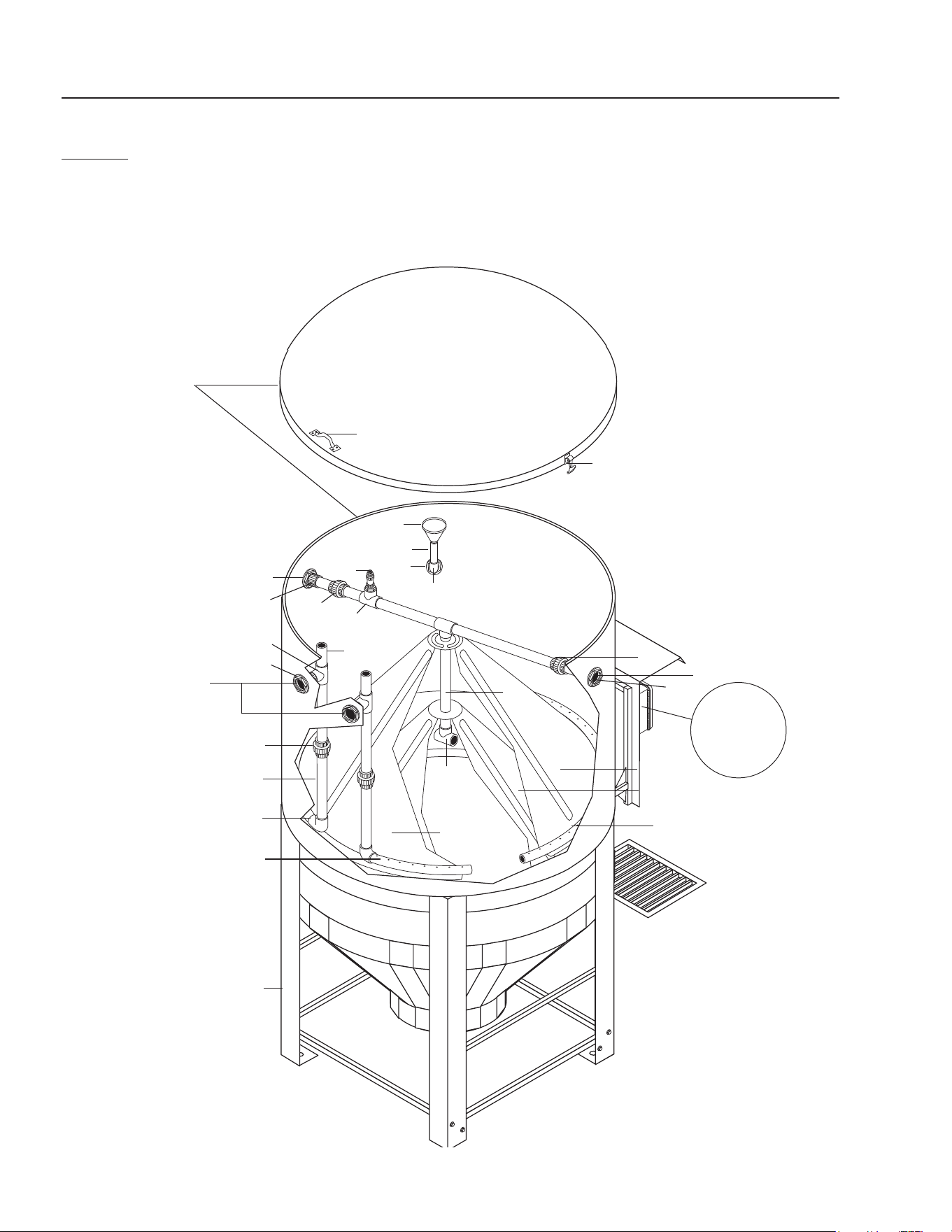
CL-30
BREAKDOWN #1
Tank Lid
Oil Skimmer
Funnel
600 Gal.
Coalescing Tank
To Flow Meter
Coalescing
Cones
To 165 Gal. Vertical
Holding Tank
Main Tank Ring
Assembly
Sump Pit
16
18
20
14
10
21
2
5
11
9
8
11
3
6
7
4
15
18
17
4
12
13
19
91
7
For Detail
See Control
Panel Illus.

CLARIFIER 30 OPERATOR’S MANUAL
11
Watermaze CL-30 • 8.913-971.0 - A
CL-30 PARTS LIST
BREAKDOWN #1
ITEM PART NO. DESCRIPTION QTY
1 8.706-367.0 Pipe, 1.5", PVC 80, /ft. 18
2 8.706-372.0 Elbow, 1-1/2" S x T, PVC 80,
90° 2
3 8.706-382.0 Elbow, 2" S x S, PVC 80, 90° 2
4 8.706-426.0 Tee, 1.5" S x S x S, PVC 80 2
5 8.706-434.0 Tee, 2" Slip x S x S, PVC 80 1
6 8.706-441.0 Adapter, 1.5" S x MT, PVC 80 2
7 8.706-469.0 Union, 1-1/2" S x S, PVC 80 4
8 8.706-473.0 Union, 2" S x S, PVC 80 4
9 8.706-479.0 Bulkhead, 2" NPT, PolyPro 4
10 8.706-568.0 Handle, Rubber T, w/Keeper 3
11 8.706-583.0 Pipe, 2", Gray, PVC 80 6
12 8.706-677.0 Cone, 3/16", Vertical
Coalescing 2
13 8.706-678.0 Cone, 1/8" Vertical Coalescing,
No Holes 1
14 8.706-683.0 Funnel, Plastic Oil Skimmer 1
15 8.707-298.0 Valve, Ball Check, 1/2" PVC 1
16 8.719-177.0 Tank, Clarifi er 600 w/Lid 1
17 8.913-091.0 Frame, CLP Tank Stand 1
18 8.706-490.0 Bulkhead, 1-1/2" 3
19 8.711-816.0 Hose, 2" Gray, Conduit 16 ft.
20 8.706-482.0 Nipple, 1-1/2" x 6", PVC 80 1
21 8.706-648.0 Handle, Sandpot 3
12
CLARIFIER 30 OPERATOR’S MANUAL
Watermaze CL-30 • 8.913-971.0 - A
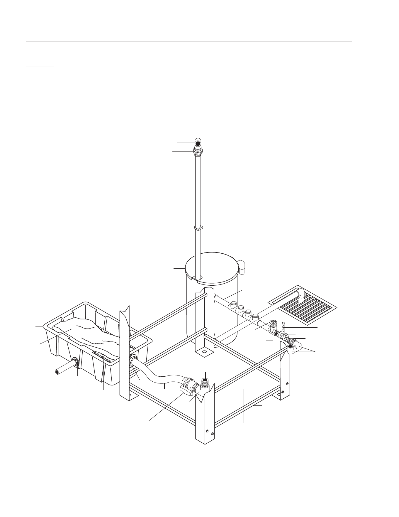
CL-30
BREAKDOWN #2
Line To Oil
Skimmer
Oil Decanter
Barrel (Standard)
Sump Pit
Flow
Meter
Gate
Valve
Sludge Tub
Return
Line To
Furthest Pit
Coalescing Tank
Main Drain Assy.
5
13
9
16
5
12
11
10
8
15
2
4
1
14
3
4
2
7
6
1
Valve #5
13

CLARIFIER 30 OPERATOR’S MANUAL
13
Watermaze CL-30 • 8.913-971.0 - A
CL-30 PARTS LIST
BREAKDOWN #2
ITEM PART NO. DESCRIPTION QTY
1 8.706-367.0 Pipe, 1.5", PVC 80, /ft. 18
2 8.706-374.0 Elbow, 1-1/2" S x S, PVC 80,
90° 3
3 8.706-421.0 Hanger, Pipe, 1-1/2" Click #47 4
4 8.706-469.0 Union, 1-1/2" S x S, PVC 80 4
5 8.706-479.0 Bulkhead, 2" NPT, PolyPro 4
6 8.707-344.0 Valve, PVC 1.5" S x S, Gate 1
7 8.712-316.0 Gauge, Flowmeter 1.5" 1
8 8.719-191.0 Bag, Sludge, Biodegradable 1
9 8.707-349.0 Valve, 2" Single Union Ball 1
10 8.719-179.0 Tub, Sludge, w/Lid (Black) 1
11 8.913-094.0 Support, CLP Sludge Bag 1
12 8.711-817.0 Hose, 2", Clear Spiralite, /ft. 8
13 8.913-096.0 Rail, CL-602, Water Panel
Mount 2
14 8.906-479.0 Tank, Oil Separation Assy. 1
15 8.706-466.0 Nipple, 2" Close, PVC 80 1
16 8.706-384.0 Elbow, 2" S x T, PVC 80 1
14
CLARIFIER 30 OPERATOR’S MANUAL
Watermaze CL-30 • 8.913-971.0 - A
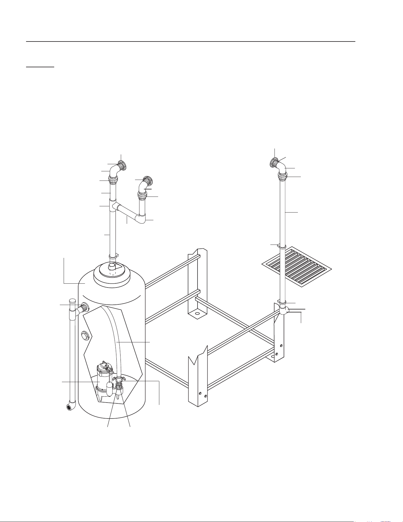
CL-30
BREAKDOWN #3
Lines To Main Tank
Ring Assembly
7
165 Gal. Vertical
Storage Tank
5
Sump
Pump
Outlet To
Main Clarifi er
System
3
Cam Lock
Connector
To Flow
Meter
Sump Pit
Line To
Coalescing
Tank
6
13
6
15
4
11
11
17
14
18
10
16
10
12
18
16
10
14
17
18
2
1
9
8

CLARIFIER 30 OPERATOR’S MANUAL
15
Watermaze CL-30 • 8.913-971.0 - A
CL-30 PARTS LIST
BREAKDOWN #3
ITEM PART NO. DESCRIPTION QTY
1 8.706-403.0 Bushing, 2" x 1-1/2" MT x FT,
PVC 80 1
2 8.706-490.0 Bulkhead, 1-1/2" PolyPro 3
3 8.707-168.0 Coupler, 1.5" Fem. x 1.5" Hose
Barb Cam. 1
4 8.706-367.0 Pipe, 1.5", PVC 80, /ft. 18
5 8.715-368.0 Pump, Little Giant Sump,
1/2 HP 230V/1PH, CL-30A 1
8.715-438.0 Pump, Ebara Sump
1/2 HP 230V/3 PH, CL-30B 1
8.715-439.0 Pump, Ebara Sump
1/2 HP 460V/3 PH, CL-30C 1
8.716-142.0 ▲ Switch, Float, N/O
CL-30B, CL-30C 1
6 8.706-374.0 Elbow, 1-1/2" S x S, PVC 80,
90° 3
7 8.719-172.0 Tank, Vertical, 165 Gallon 1
8 8.711-813.0 Hose, 1-1/2" Gray Spiralite
9 8.707-169.0 Adapter,
1.5" Male x 1.5" Cam Lock 1
10 8.706-382.0 Elbow, 2" S x S, PVC 80, 90° 2
11 8.706-421.0 Hanger, Pipe, 1-1/2" Click #47 4
12 8.706-434.0 Tee, 2" Slip x S x S, PVC 80 1
13 8.706-441.0 Adapter, 1.5" S x MT, PVC 80 2
14 8.706-451.0 Adapter, 2" S x MT, PVC 80 1
15 8.706-469.0 Union, 1-1/2" S x S, PVC 80 4
16 8.706-473.0 Union, 2" S x S, PVC 80 4
17 8.706-479.0 Bulkhead, 2" NPT, PolyPro 4
18 8.706-583.0 Pipe, 2", Gray, PVC 80 5.6
▲ Not Shown
16
CLARIFIER 30 OPERATOR’S MANUAL
Watermaze CL-30 • 8.913-971.0 - A
CL-30 - THREE PHASE ONLY
CONTROL PANEL
3
9
6
2
7
1
4
5
8
13

CLARIFIER 30 OPERATOR’S MANUAL
17
Watermaze CL-30 • 8.913-971.0 - A
CL-30 PARTS LIST - THREE PHASE ONLY
CONTROL PANEL
ITEM PART NO. DESCRIPTION QTY
1 8.716-460.0 Terminal, Grounding Lug,
LAMA6-14-Q 1
2 9.802-474.0 Box, Plastic, VNG Remote,
VYNCKIER 1
3 8.716-081.0 Protector, Toggle Switch,
WTRPRF 1
4 8.716-078.0 Switch, Toggle, 1-1/2HP, 1 Pole
P#CA201-73 1
5 8.716-083.0 Plate, ON-OFF, Toggle Switch
(YO1) 1
6 8.716-733.0 Contactor, 24V,
CH CE15BNS3TB, CL-30B 1
7 8.716-776.0 Overload, 2.80-4.00 AMP,
CH C316FNA3K, CL-30B 1
8 9.802-553.0 Transformer, Micron,
120/240V - 24V, .050KVA 1
9 8.941-061.0 Bracket, Elec. Box Mount,
CL-30 1
10 9.802-514.0 ▲ Strain Relief, STRT, LQ Tite
3231 Small 3
11 9.802-525.0 ▲ Locknut, 1/2" 8463 3
12 8.913-122.0 ▲ Standoff, Small Electrical 1
13 8.940-055.0 Label, Assembled in USA 1
▲ Not Shown
18
CLARIFIER 30 OPERATOR’S MANUAL
Watermaze CL-30 • 8.913-971.0 - A
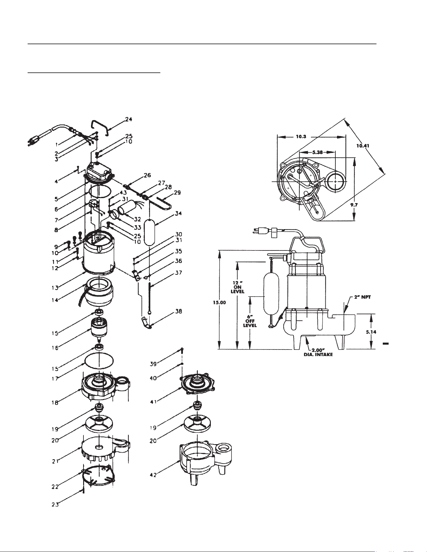
SUBMERSIBLE SUMP PUMP
8.715-368.0, 230V SINGLE PHASE
8.715-438.0, 230V THREE PHASE (NOT SHOWN)
8.715-439.0, 460V THREE PHASE (NOT SHOWN)
CLARIFIER 30 OPERATOR’S MANUAL
19
Watermaze CL-30 • 8.913-971.0 - A
ITEM PART NO. DESCRIPTION QTY
1 84-951256 Wiring Harness 25 ft. 115V 1
84-951402 Wiring Harness 25 ft. 230V 1
2 84-902437 Screw, #6 - 32 x 1/4" 1
3 84-921059 Washer, Lock 1
4 84-909022 Screw/Washer, 10 - 24 x 5/8" 4
5 84-106350 Switch Housing 1
6 84-928002 Seal Ring, Nitrile 1
7 84-950250 Switch 1
8 84-902431 Screw, 3-18 x 1/2" 2
9 84-950431 Terminal, Feed Through 3
10 84-924006 O-Ring, Nitrile 5
11 84-903710 Screw, Cap 3
12 84-921024 Washer, Lock 3
13 84-110044 Housing, Motor 1
14 84-979441 Stator, Assy, 10, PCSC 115V 1
84-979544 Stator, Assy, 10 PCSC 230V 1
15 84-948004 Ball Bearing 2
16 84-979443 Rotor, 10, PSC 115V 1
84-979543 Rotor, 10, PSC 230V 1
17 84-928001 Seal Rink, Nitrile 1
18 84-111223 Volute, Plate 1
19 84-926034 Seal, Shaft 1
20 84-111252 Impeller, Assy. 1
24 84-108101 Handle 1
25 84-947003 Plug, Oil 2
26 84-106372 Lever Arm Assy. 1
27 84-106377 Washer, Plain Polyethylene 1
28 84-950940 Plug, Screw Hex 1
29 84-106359 Protection Rod 1
ITEM PART NO. DESCRIPTION QTY
30 84-902516 Screw, Tapping, 10 - 24 x 1/2" 1
31 84-921023 Washer, Lock 2
32 84-950507 Capacitor, Assy., 10-SFS 1
33 84-110101 Bracket, Capacitor 1
34 84-106362 Float 1
35 84-110100 Retainer, Float Rod Strap 1
36 84-929451 Push-In Fastener 1
37 84-106381 Rod, Float 1
38 84-106367 Strap, Float 1
39 84-915907 Bolt, Hex 4
40 84-921103 Washer, Lock 4
41 84-111423 Plate, Housing 1
42 84-111415 Volute 1
43 84-902520 Screw, 10 - 24 x 3/8" 1
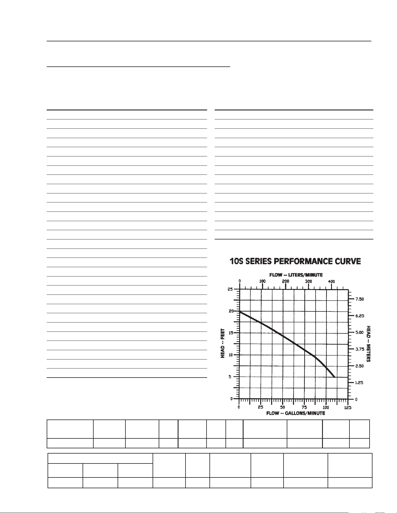
MODEL
NO.
PART
NO. LISTING HP VOLTS HZ PH
SOLID SIZE
(DIA.IN.)
RUNNING
AMPS
START
AMPS RPM
10S-CIA-SFS 5-23485 UL/CSA 1/2 230 60 1 2 4.6 10 1750
PERFORMANCE (GPM @ HEAD) SHUT-
OFF
(FT.) PSI
PWR. CORD
(FT.)
WEIGHT
(LBS.)
DIMENSIONS
(HxLxW) IN.
MAX. WATER
TEMP.
5 ft. 10 ft. 15 ft.
110 85 45 20 8.7 25 47 15x10.3x9.62 140
o
F/60
o
C
SUBMERSIBLE SUMP PUMP - PARTS LIST
8.715-368.0, 230V SINGLE PHASE
8.715-438.0, 230V THREE PHASE (NOT SHOWN)
8.715-439.0, 460V THREE PHASE (NOT SHOWN)

20
CLARIFIER 30 OPERATOR’S MANUAL
Watermaze CL-30 • 8.913-971.0 - A
Pump
PROBLEM POSSIBLE CAUSE SOLUTION
PUMP DOES NOT
TURN ON
Circuit breaker shutoff or fuse re-
moved
Turn on circuit breaker or replace fuse.
Accumulation of trash on pump fl oat Clean fl oat.
Pump fl oat obstruction Check fl oat path and provide clearance.
Defective fl oat switch Have pump serviced by authorized service
center.
Defective motor Have pump serviced by authorized service
center.
Low line voltage If voltage under recommended minimum,
check size of wiring from main switch on
property. If OK, contact power company.
PUMP WILL NOT
SHUT OFF
Float obstruction Check fl oat and fl oat rod path and provide
clearance.
Defective fl oat switch Disconnect switch, check w/ohm meter
PUMP RUNS BUT
DOES NOT
DISCHARGE LIQUID
Lift too high for pump Check rating table.
Inlet to impeller plugged Pull pump and clean.
Low line voltage If voltage under recommended minimum,
check size of wiring from main switch on
property. If OK, contact power company.
Clogged impeller Remove housing and unclog.
Faulty motor protector Replace pump.
Very low head or lift Increase head or lift.
Sump pit too small Increase size of pit.
PUMP DOES NOT
DELIVER RATED
CAPACITY
Low voltage, speed too slow Check for proper supply voltage to make
certain it corresponds to nameplate voltage.
Impeller or discharge pipe clogged Pull pump and clean. Check pipe for scale
or corrosion.
Impeller wear due to abrasives Replace worn impeller.
PUMP CYCLES
CONTINUALLY
Low line voltage If voltage is under recommended minimum,
check size of wiring from main switch on
property. If OK, contact power company.
Worn or defective pump parts or
plugged impeller
Replace worn parts or entire pump. Clean
parts if required.
Pump air locked Turn pump On-Off several times. Fill hose
manually with water.
TROUBLESHOOTING
CLARIFIER 30 OPERATOR’S MANUAL
21
Watermaze CL-30 • 8.913-971.0 - A
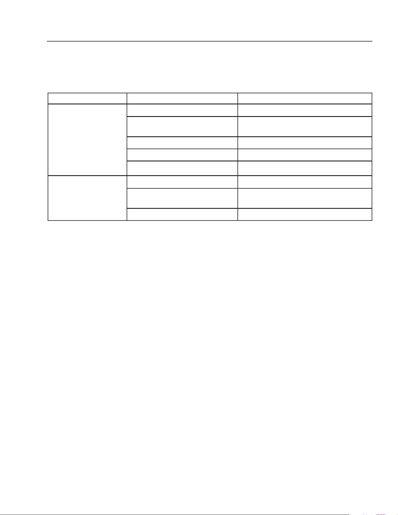
TROUBLESHOOTING
Clarifi er
PROBLEM POSSIBLE CAUSE SOLUTION
NO FLOW OF WATER
INTO THE CLARIFIER
Power not turned on at breaker box Turn on power at breaker box.
Debris in pump impeller Unplug pump and remove from sump. Check
impeller. Clean and repair if necessary.
Flow control valve in off position Open valve.
Dirt lodged in control valve Clean as needed.
Frozen water in lines or valves Thaw out with warm water.
WATER FLOWING
OVER CLARIFIER
Tank not level Level tank.
Water coming into the Clarifi er faster
than 5 - 25 GPM
Adjust the fl ow control valve.
Discharge line plugged Remove obstruction.

22
CLARIFIER 30 OPERATOR’S MANUAL
Watermaze CL-30 • 8.913-971.0 - A
SPECIFICATIONS
MODEL CL-30
MAXIMUM FLOW
30 gpm
OIL/WATER SEPARATOR CAPACITY
600 gal.
SOLIDS SEPARATION CHAMBER
Ye s
ELECTRICAL
230 Volt 1 PH 4.6 Amps
230 Volt 3 PH 3.5 Amps
460 Volt 3 PH 3.0 Amps
SUMP PUMP SUBMERSIBLE
1/2 HP
OIL SKIMMER
Ye s
COALESCING PACK
68 sq. ft.
CLARIFIED HOLDING TANK
165 gal.
DIMENSIONS (L x W x H)
60" x 83" x 106"
NET DRY WEIGHT (approx)
825 lbs.

CLARIFIER 30 OPERATOR’S MANUAL
23
Watermaze CL-30 • 8.913-971.0 - A
WATER MAZE LIMITED NEW PRODUCT WARRANTY
WASH-WATER SYSTEMS
WHAT THIS WARRANTY COVERS
All WATER MAZE wash-water systems are warranted by WATER MAZE to the original purchaser to be free from defects in
materials and workmanship under normal use, for the periods specifi ed below. This Limited Warranty, subject to the exclusions
shown below, is calculated from the date of the original purchase, and applies to the original components only. Any parts replaced
under this warranty will assume the remainder of the part’s warranty period. A 60 day grace period will be given for installation.
ONE YEAR PARTS AND 30 DAY LABOR WARRANTY:
All components excluding normal wear items as described below.
WARRANTY PROVIDED BY OTHER MANUFACTURERS:
Motors, which are warranted by their respective manufacturers, are serviced through these manufacturers’ local authorized
service centers. WATER MAZE cannot provide warranty on these items.
NON-WARRANTY REPLACEMENT PARTS:
These parts, excluding normal wear items as described below, will be warranted for the duration specifi ed by the original com-
ponent manufacturer. O-rings and leaks at glued fi ttings are covered the fi rst time on original start-up only.
WHAT THIS WARRANTY DOES NOT COVER
This warranty does not cover the following items:
1. Normal wear items, such as mechanical seals, fi lters, gaskets, O-rings, check valves, fi ltering media, ozone bulbs.
O-rings and leaks at glued fi ttings are covered the fi rst time on original start-up only.
2. Damage or malfunctions resulting from accidents, abuse, modifi cations, alterations, incorrect installation, improper
servicing, failure to follow manufacturer’s maintenance instructions, or use of the equipment beyond its stated usage
specifi cations as contained in the operator’s manual.
3. Damage due to freezing, chemical deterioration (oxidation, chloride or fl uoride corrosion).
4. Damage to components from fl uctuations in electrical or water supply.
5. Normal maintenance service, including adjustments.
6. Transportation to service center, fi eld labor charges, or freight damage.
7. Death of microbes (Biostax 900 & 100) from lack of refrigeration after received and stored.
WHAT YOU MUST DO TO OBTAIN WARRANTY SERVICE
While not required for warranty service, we request that you register your WATER MAZE Product by returning the completed
registration card. In order to obtain warranty service on items warranted by WATER MAZE, you must return the product to your
Authorized WATER MAZE Dealer, freight prepaid, with proof of purchase, within the applicable warranty period. If the product is
permanently installed, you must notify your Authorized WATER MAZE Dealer of the defect. Your Authorized WATER MAZE Dealer
will fi le a claim with WATER MAZE, who must subsequently verify the defect. In most cases, the part must be returned to WATER
MAZE freight prepaid with the claim. For warranty service on components warranted by other manufacturer’s, your Authorized
WATER MAZE Dealer can help you obtain warranty service through these manufacturers’ local authorized service centers.
LIMITATION OF LIABILITY
WATER MAZE’S liability for special, incidental, or consequential damages is expressly disclaimed. In no event shall
WATER MAZE’S liability exceed the purchase price of the product in question. WATER MAZE makes every effort to ensure that
all illustrations and specifi cations are correct, however, these do not imply a warranty that the product is merchantable or fi t for a
particular purpose, or that the product will actually conform to the illustrations and specifi cations. THE WARRANTY CONTAINED
HEREIN IS IN LIEU OF ALL OTHER WARRANTIES, EXPRESS OR IMPLIED, INCLUDING ANY IMPLIED WARRANTY OF
FITNESS FOR THE PARTICULAR PURPOSE, INCLUDING QUALITY OF WATER TREATMENT. WATER MAZE does not au-
thorize any other party, including authorized WATER MAZE Dealers, to make any representation or promise on behalf of WATER
MAZE, or to modify the terms, conditions, or limitations in any way. It is the buyer’s responsibility to ensure that the installation
and use of WATER MAZE products conforms to local codes. While WATER MAZE attempts to assure that its products meet
national codes, it cannot be responsible for how the customer chooses to use or install the product.
WATERMAZE
1-360-833-2333 • 1-800-535-0941 • www.wmaze.com

8.913-971.0 • Printed in U.S.A.