OPERATOR’S MANUAL
For technical assistance or the Water Maze Dealer nearest you consult our web page at
www.wmaze.com
8.913-968.0-C 07/13/18
■
CL-600
■
CL-603
CLARIFIER
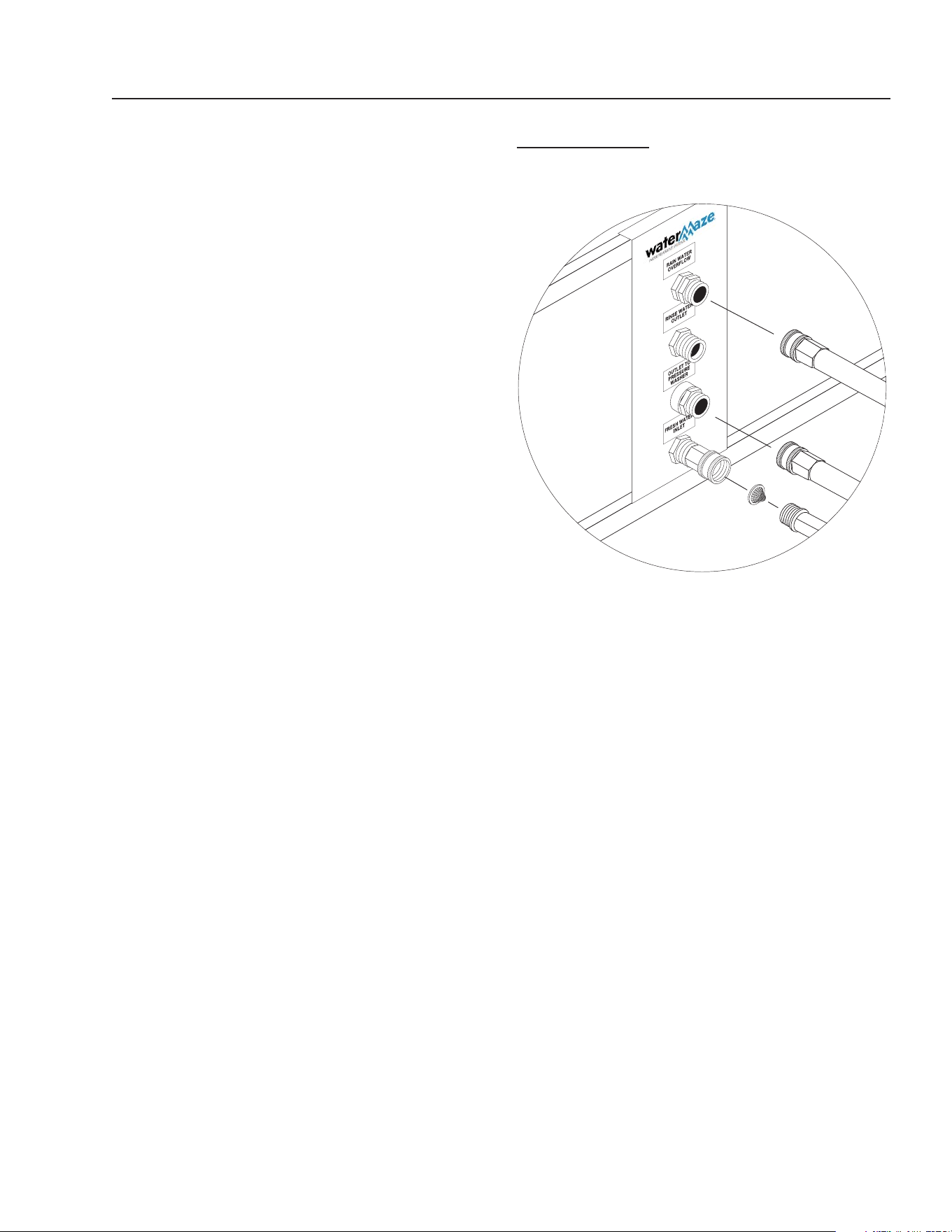
RAIN WATER
OVERFLOW
RINSE WATER
OVERFLOW
OUTLET TO
PRESSURE
WASHER
FRESH WATER
INLET
Assembled in USA
C
o
n
t
ai
n
s
c
ompone
n
ts
fr
o
m
o
n
e
or
mo
re
o
f
th
e
foll
owing
c
ou
n
t
r
i
es
: Un
i
ted Sta
tes,
A
u
str
i
a
,
Brazi
l,
Canada,
C
h
in
a
,
E
ngl
an
d
,
Fr
a
n
c
e,
H
o
n
dur
as
,
I
t
al
y
,
Jap
an, M
e
x
i
c
o,
Rom
a
n
i
a,
Taiwan
,
T
hai
l
a
nd
,
Vietnam.
INTEND
E
D FO
R I
NDOOR
USE
89139680-1

Introduction .................................................................................................................................... 4
Unpacking ...................................................................................................................................... 4
Safety Instructions ......................................................................................................................4-5
System Safety Information ............................................................................................................. 5
Installation Instructions ...............................................................................................................6-8
CL-600 Installation ..................................................................................................................6-7
CL-603 Installation ..................................................................................................................... 8
Start-Up ......................................................................................................................................... 9
Operation ....................................................................................................................................... 9
Float Level Controls ....................................................................................................................... 9
Clarifi er Assembly (All Models) .................................................................................................... 10
Optional Filter Pac III, #30-778 .................................................................................................... 11
Valve Location and Function ...................................................................................................12-13
Valve Descriptions ................................................................................................................... 14
Filling System with Water ......................................................................................................... 14
Running ................................................................................................................................... 14
Backwash Multi-Media Filter, Filter Pac III (CL-603) ................................................................ 14
Backwash Carbasorb Filter, Filter Pac III (CL-603) .................................................................. 15
General Maintenance and Service ......................................................................................... 15-16
Periodic Maintenance .............................................................................................................. 13
Cartridge Filter ......................................................................................................................... 13
Remove/Replace Cartridges ................................................................................................... 13
Reinstalling Cartridges ............................................................................................................ 13
Cleaning Cartridges ................................................................................................................. 14
Winterizing ............................................................................................................................... 14
Testing Carbon ............................................................................................................................. 14
Chemical Maintenance Program ............................................................................................ 14-15
Daily Chemical Maintenance ....................................................................................................... 15
Pump Operation (Ozone, Filter or Transfer) ................................................................................. 16
Pump Maintenance (Sump) ......................................................................................................... 16
Ozone Generator ....................................................................................................................16-20
Ozone... Nature’s Purifi cation Agent ........................................................................................ 16
How the Clarifi er Ozone System Works ................................................................................... 16
Ozone Generator Maintenance ..........................................................................................16-17
Specifi cations .......................................................................................................................... 17
Ozone Generator Testing Procedure ....................................................................................... 18
Ozone Generator Breakdown, Series 400 ............................................................................... 19
CONTENTS
CL-600 • #8.913-968.0 -C

3
Model Number ______________________________
Serial Number ______________________________
Date of Purchase ____________________________
The model and serial numbers will be found on a decal attached
to the machine. You should record both serial number and date of
purchase and keep in a safe place for future reference.
CL-600 • #8.913-968.0 -C
CONTENTS
Ozone Measurement System ...................................................................................................... 20
ORP/pH Meter Installation ....................................................................................................... 20
ORP and pH Sensors .............................................................................................................. 20
Cartridge Filter Assembly, Filter Pac II, III .................................................................................... 21
Carbon Filter, Filter Pac I & III/Multi-Media Filter, Filter Pac III ................................................... 22
6 Position Valve ........................................................................................................................... 23
Transfer Pump #8.715-402. 0, 8.714-404.0 (CL-603) .................................................................. 24
Ozone Generator Pump Assy. (CLB603A, CL600D) ................................................................... 25
Ozone Generator Pump Assy. (CLB603B,C) ............................................................................... 26
Filter Pump, Filter Pac III ............................................................................................................ 27
Water Panel Assembly and Parts List (603) ........................................................................... 28-29
Storage Tank Assembly and Parts List (603) ..........................................................................30-31
Transfer Pump Assembly and Parts List (603) ........................................................................32-33
Ozone Oil Bucket/Sludge Tub Assembly and Parts List (600/603) .........................................34-35
Optional Filter Pac III Assembly and Parts List .......................................................................36-37
Ozone Generator Series 400 Assembly and Parts List ..........................................................38-39
Ozone Generator Four Tube Assembly ........................................................................................ 40
Control Panel Assembly and Parts List ................................................................................... 41-43
Troubleshooting ......................................................................................................................42-49
Clarifi er ........................................................................................................................................ 44
Pump ....................................................................................................................................... 45
Pump Motor ............................................................................................................................. 46
Filter ......................................................................................................................................... 47
Water Solenoid ........................................................................................................................ 48
Water Seals ............................................................................................................................. 49
Specifi cations ............................................................................................................................... 50
Consumable Parts List ................................................................................................................. 51
Warranty
4
CLARIFIER SERIES OPERATOR’S MANUAL
CL-600 • #8.913-968.0 -C
INTRODUCTION
Your owner’s manual has been prepared to provide you with
a simple and understandable guide for equipment operation
and maintenance, based on the latest product information
available at the time of printing. To keep your machine in
top running condition, follow the specifi c maintenance and
troubleshooting procedures given in this manual.
Owner/User Responsibility:
The owner and/or user must have an understanding
of the manufacturer’s operating instructions and warn-
ings before using this WATER MAZE machine. Warning
information should be emphasized and understood. If
the operator is not fl uent in English, the manufacturer’s
instructions and warnings shall be read to and discussed
with the operator in the operator’s native language by
the purchaser/owner, making sure that the operator
comprehends its contents.
The owner and/or user must study and maintain the
manufacturers’ instructions for future reference.
NOTE: WATER MAZE reserves the right to make chang-
es at anytime without incurring any obligations.
SAVE THESE INSTRUCTIONS
This manual should be considered a permanent part
of the machine and should remain with it if machine
is resold.
When ordering parts, please specify model and
serial number. Use only identical replacement parts.
This machine is to be used only by trained operators.
UNPACKING
1. 600 gallon water tank
2. Coalescing cone assembly
3. Electrical panel
4. Sump pump assembly
5. Ozone pump assembly
6. Ozone generator
7. Oil water separator barrel
8. Oil skimmer
9. Discharge barrel(s) (CL-603)
10. Waste collection bag and tub
11. Exterior plumbing
12. Fresh water make-up fl oat (CL-603)
13. High level control fl oat (CL-603)
14. Test strips
15. Operator’s manual
16. Low water shut-off (CL-600)
17. Filter pack (CL-603)
Note any damage to machine or components for claims
against the freight lines.
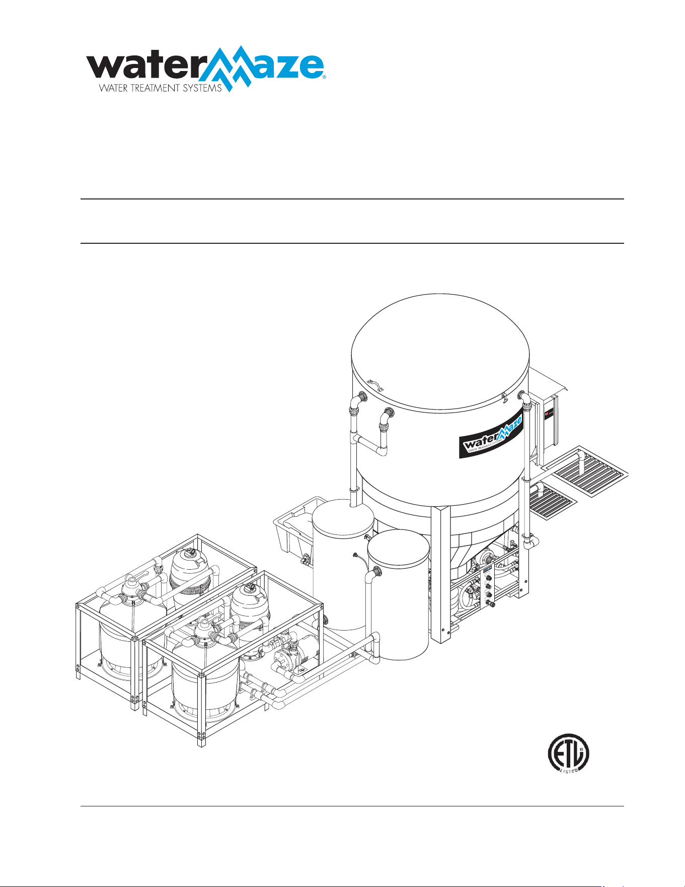
SAFETY INSTRUCTIONS
WARNING: To reduce the risk of
injury, read operating instructions
carefully before using.
1. Read the owner’s manual
thoroughly. Failure to follow
the instructions will cause a
malfunction of the machine and
result in death, serious injury
and/or property damage.
DANGER: Meet the National Elec-
trical Code and local codes for all
wiring.
DANGER: Follow the wiring in-
structions in this manual when
connecting the system to the
power lines.
DANGER: All wiring must be per-
formed by a qualifi ed electrician.
A ground fault circuit interrupter must be used.
DANGER: Machine must be electrically grounded.
DANGER: Never spray water near any electrical
components.
DANGER: Make sure that machine is not in operation
before making adjustments.
2. The installation of this machine must comply with
local and/or national codes.
3. Never make adjustments on the machine while it
is in operation, except for those prescribed in this
manual.
WARNING: Do not discharge
concentrations of fl ammable or
explosive fl uids such as gasoline,
fuel oil, kerosene, etc. into the
Clarifi er. Do not use in explosive
atmospheres. Failure to follow
this warning can produce an
explosion resulting in personal
injury and/or property damage.
4. Do not discharge gasoline or other volatile hydrocar-
bons into the Clarifi er. This could cause a gas vapor
build-up inside the Clarifi er which could become an
explosive mixture.
5. Before servicing the machine, refer to the MSDS’s
on all the material identifi ed in the waste stream. You
must comply with all warnings and wear all protective
clothing as stated on the MSDS’s.
6. Protect inlet and outlet pipes from vehicle traffi c and
sharp objects.
7. Inlet water temperature must not exceed 85° F.
WARNING
RISK OF
EXPLOSION: DO NOT
USE WITH FLAM-
MABLE LIQUIDS.
WARNING
READ OPERATOR’S
MANUAL THOROUGH-
LY PRIOR TO USE.
HAZARDOUS
VOLTAGE. CAN
SHOCK, BURN OR
CAUSE DEATH.
DANGER
CLARIFIER SERIES OPERATOR’S MANUAL
5
CL-600 • #8.913-968.0 -C
8. When making repairs, disconnect the machine from
its electrical source.
9. The best insurance against an accident is precaution
and knowledge of the equipment.
10. WATER MAZE is not liable for modifi cations or use of
components not purchased from WATER MAZE.
11. Clarifi er and components will freeze and in cold
climates must be located in a heated enclosure.
12. Running the system without water will damage the
pumps and will void the warranty.
At time of installation, the fl ow into the Clarifi er must be
set. The Clarifi er will then run virtually unattended. NOTE:
Maintenance and water tests must be done routinely.
SYSTEM SAFETY
INFORMATION
1. Know the system application, limitations and poten-
tial hazards.
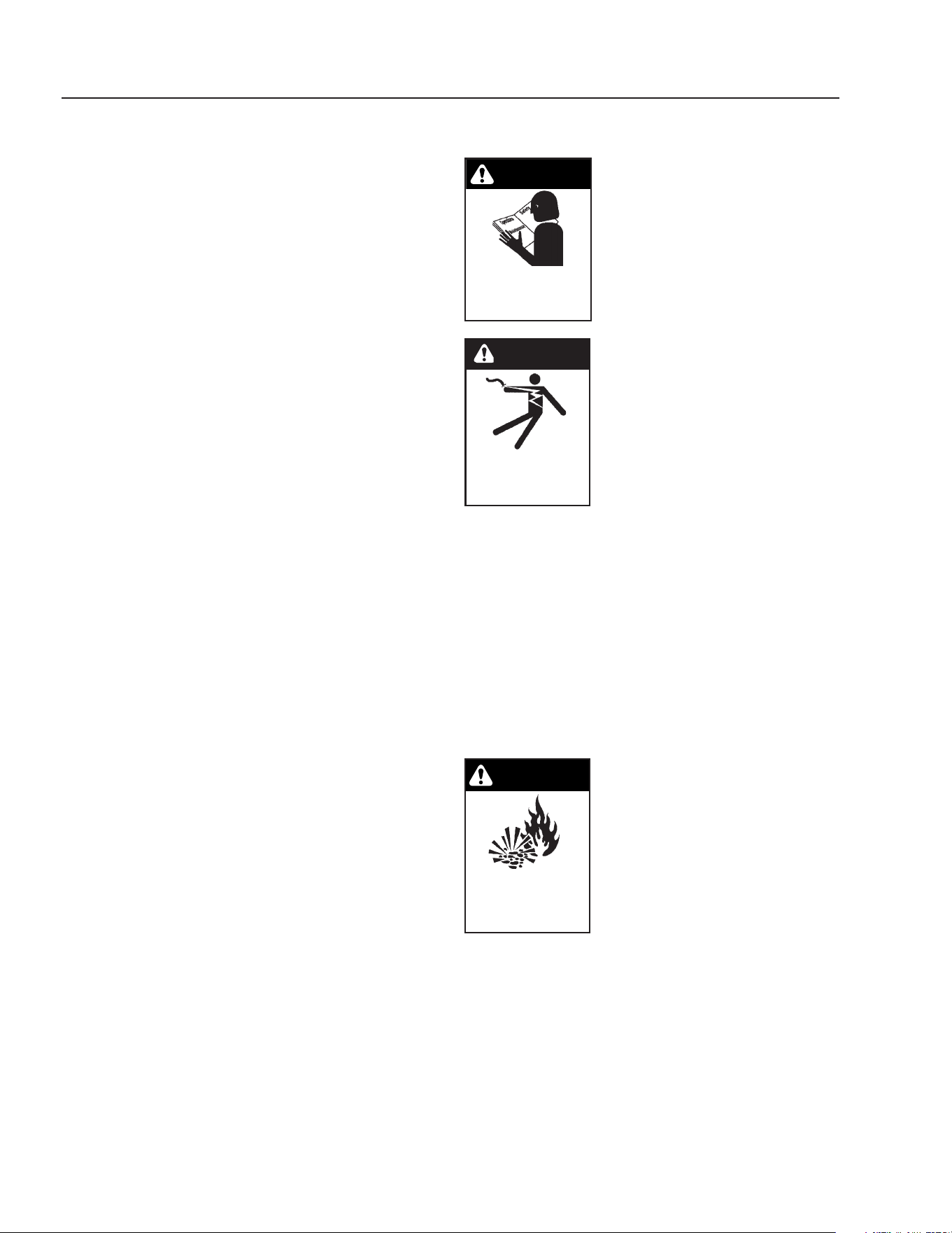
WARNING: Do not use to pump con-
centrations of fl ammable or explo-
sive fl uids such as gasoline, fuel oil,
kerosene, etc. Do not use in explosive
atmospheres. Pumps should only be
used with liquids compatible with
pump component materials. Failure
to follow this warning can result in
personal injury and/or property
damage.
2. Make certain that the power source conforms to the
Clarifi er electrical requirements. (Check the serial
plate for proper voltage and amperage require-
ments.)
3. Disconnect the power before servicing.
4. Release all pressure within the system before
servicing any component.
5. Drain all liquids from the component before
servicing.
6. Check hoses for weak or worn condition before each
use, making certain that all connections are secure.
7. Periodically inspect pump and system components.
Perform routine maintenance as required.
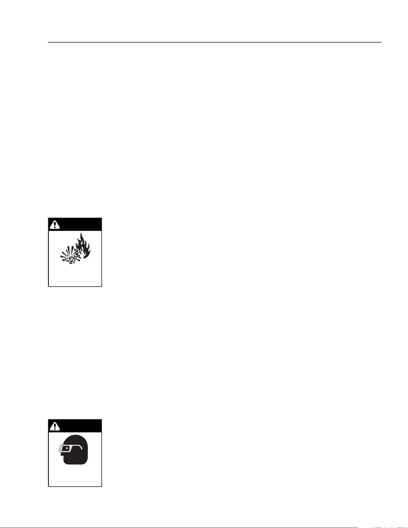
WARNING: Wear protective eye-
wear, foot protection and protec-
tive clothing.
8. Personal Safety:
a. Wear safety glasses and
other applicable protective
clothing at all times when
working on the Clarifi er.
NOTE: Refer to item #5 under Safety Instructions.
b. Keep your work area clean, uncluttered and
properly lighted. Replace all unused tools and
equipment.
c. Keep visitors at a safe distance from the work
area.
d. Make the workshop safe with padlocks and
master switches.
9. When wiring an electrical system, follow all electrical
and safety codes, as well as the most recent National
Electrical Code (NEC) and the Occupational Safety
and Health Act (OSHA).
WARNING: Risk of electric shock.
10. All wiring should be performed by a qualifi ed electri-
cian.
11. The main power must be brought from the circuit
breaker and wired into the electrical box on the Clari-
fi er. This line must be run through conduit to protect it
from damage. A power disconnect should be located
next to the machine for maintenance purposes.
12. Protect all electrical cords from sharp objects, hot
surfaces, oil, sunlight and chemicals. Avoid kink-
ing the cords. Replace or repair damaged or worn
cords immediately. All wiring should be run through
conduit.
13. Use wire of adequate size to minimize voltage drop
at the motor.
14. Disconnect the power before servicing a motor. If the
power disconnect is out-of-sight, lock it in the open
position and tag it to prevent unexpected application
of power.
15. Do not touch an operating motor. Modern motors
are designed to operate at high temperatures.
16. Do not handle a pump or pump motor with wet hands
or when standing on a wet or damp surface or in
water.
17. All single phase pump motors are equipped with an
automatic resetting thermal protector and may re-
start unexpectedly. Tripping is an indication of motor
overloading as a result of operating the pumps at low
heads (low discharge restriction), excessively high
or low voltage, inadequate wiring, incorrect motor
connections or a defective motor or pump.
18. IMPORTANT NOTE: The sump pump is not a trash
pump and is subject to premature failure unless
sump baffl ing or additional protection is provided.
WARNING
RISK OF EXPLOSION:
DO NOT USE WITH
FLAMMABLE LIQUIDS.
WARNING
USE PROTECTIVE
CLOTHING WHEN
OPERATING.
6
CLARIFIER SERIES OPERATOR’S MANUAL
CL-600 • #8.913-968.0 -C
INSTALLATION INSTRUCTIONS
The Clarifi er has been designed for indoor use only.
Machine must be stored indoors when not in use.
CL-600 Installation
1. Locate B6 on the stand. Locate pipe labeled P6.
Take P6 and thread the close nipple into the bulk-
head fi tting labeled B6. Tighten it down so it will not
leak. Make sure the pipe is pointed down. Remove
the nut from the bulkhead fi tting on B1 (See Fig. 4)
and insert the threads of the bulkhead fi tting through
the hole labeled B1. Replace the nut and tighten
it down so it will not leak. The pipe P1 should be
pointed down. NOTE: All the o-rings are in a plastic
bag and must be placed in the unions as the instal-
lation progresses.
2. Find the pipes P3 and P4. Locate the bulkheads
labeled B3 and B4. Thread the close nipples into
the bulkheads. Make sure they are tight so they
will not leak and the pipes are pointed down (see
fi g. 4). Now connect the P3 and P4 pipes that are
connected with a tee, to the unions on the P3 and
P4 pipes that were just installed into the B3 and B4
bulkheads. Make sure you replace the o-rings in the
unions before connecting.
3. Connect the A6 unions together inside the Clari-
fi er. Thread the A1 close nipple with 90° elbow and
threaded nipple into the B1 bulkhead fi tting. The pipe
should be pointed up. Now thread the funnel onto
the threaded nipple. This will be adjusted later when
the Clarifi er is running (see fi g. 4).
4. Find pipe P2. Locate B2 on the Clarifi er. Remove
the nut from the bulkhead and place the threaded
portion through the hole labeled B2. Replace the nut
and tighten it down so that it will not leak. Thread
the 1" elbow with nipple (A2) into the B2 bulkhead.
Point the nipple towards the back of the tank. Next
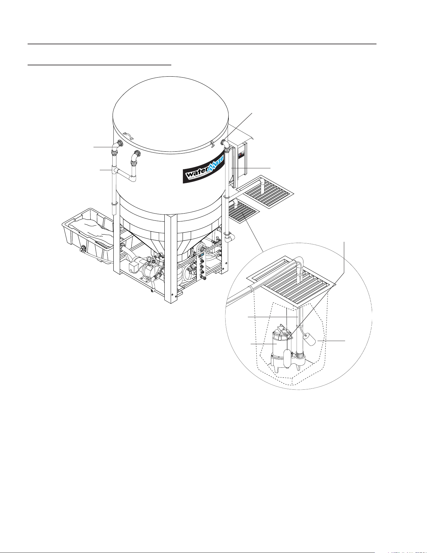
Sump
Pump
Installation
Sump
Pit
Sump
Pump
Inlet
Line
FS1
CLARIFIER 600 INSTALLATION
FIGURE 1
B3
P3
B6
P6
Sump Pump Not
Supplied with Machine.
See Specifi cation on
Page 25.
CLARIFIER SERIES OPERATOR’S MANUAL
7
CL-600 • #8.913-968.0 -C
connect P2 to the union coming off of the ozone
pump. Locate pipe P5. Find the hole B5 on the tank.
Remove the nut from the bulkhead fi tting and place
the threaded portion through the hole. Replace the
nut and tighten it down so that it will not leak. Con-
nect P5 to the union on the inlet side of the ozone
pump.
5. Connect the top P6 union and secure the pipe into
the clips provided on the frame (see fi g. 4).
6. Connect the P1 union. Secure the pipe into the clip
provided on the frame. The P1 pipe glues into the
inlet of the oil collection bucket.
7. Connect the 2" pipe labeled P3 P4 into the union.
Since this is a CL-600, installation, this 2" discharge
pipe will be plumbed to the sewer. NOTE: Discharge
permits are required and must be obtained before
the start-up of the CL-600. Use 45° elbows to help
with the fl ow on gravity feed lines.
8. The return line to the pit, P7, is 1-1/2". This starts by
gluing pipe into the adapter on the waste collection
tub. Now connect the return line from the oil collec-
tion bucket to the return line to the pit. If you want to
set up the CL-600 to recirculate, tee into the return
line (P7) with the line to sewer, with valves to direct
the fl ow to the sewer or the pit. Use a 2” line from
where you tee in with P7 to the pit.
9. Use 1-1/2" pipe and build the inlet plumbing from the
sump to the Clarifi er. If the pipe is to be under the
concrete, use 2" pipe. Connect the plumbing from
the discharge side of the sump pump and run it to
the Clarifi er. Connect the P6 union, near the 1-1/2"
gate valve, to fi nish the manifold assembly. Glue the
inlet plumbing from the sump to the 90° elbow near
the leg of the stand and clip the pipe in place (see
fi g. 4).
10. Install the normally open fl oat switch (FS1) in the pit.
Attach the fl oat to the suction line, 6" to 8" from the
bottom of the pipe. Wire the fl oat into the electrical
box on terminal blocks per wiring diagram.
NOTE: The lower section of pipe P6 comes standard
without any fi ttings glued. This is to facilitate the different
locations of the horizontal inlet pipe. When plumbing,
use the fi ttings provided and use the correct schedule
80 pipe glue. Secure the pipe to the stand leg with the
pipe holder.
NOTE: The Clarifi er lid hold down clips must be installed
in the fi eld. All hardware is provided. A silicone sealant
should be used to prevent leakage in cone tank.
CLARIFIER
FIGURE 2
ELECTRICAL
The machine, when installed, must be electrically
grounded in accordance with local and/or national codes.
Check for proper electrical supply. It is recommended that
a ground fault circuit interrupter be installed in the circuit
breaker for all WATER MAZE equipment. The fl oats in the
sump run on 24 volts. For Clarifi er model CL-03, check
the serial plate for voltage requirements and amp loads.
NOTE: Always test all electrical power supplies for proper
voltage before wiring into any equipment. Always verify
voltage and amperage requirements on the serial plate
before testing electrical supplies.
CHECK LIST BEFORE
STARTING
YES NO
1. Is inlet line connected from the sump
pump to the inlet of the Clarifi er? ___ ___
2. Is the voltage correct? ___ ___
3. Is the recycle line connected? ___ ___
4. Is the fresh water make-up hose con-
nected? ___ ___
5. Are the fl oats adjusted correctly? ___ ___
Water
Panel
(Front View)
8
CLARIFIER SERIES OPERATOR’S MANUAL
CL-600 • #8.913-968.0 -C
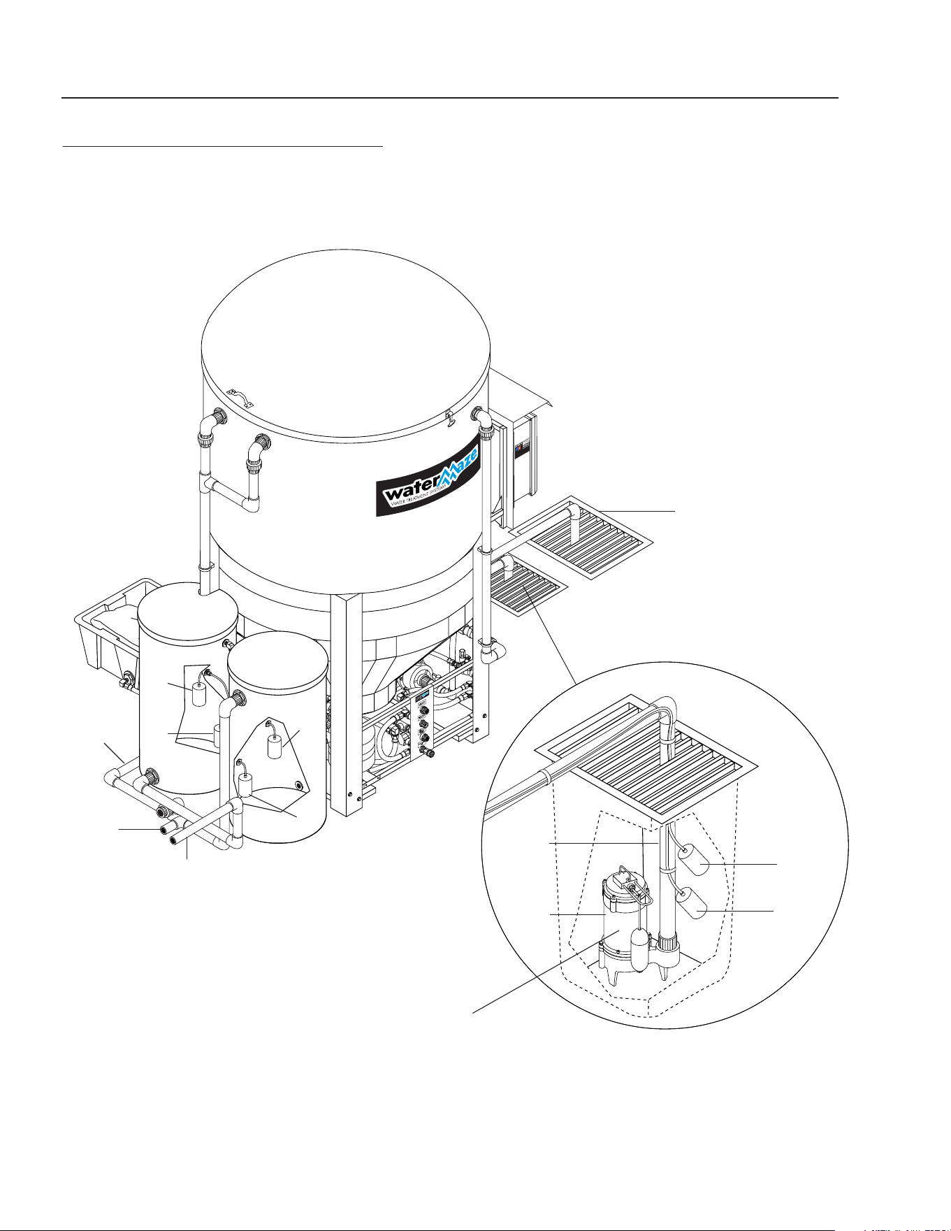
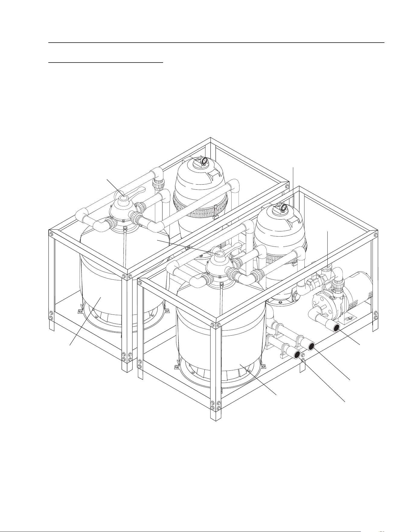
CLARIFIER 603 INSTALLATION
FIGURE 3
Connections
To Optional
Filter Pac
Pallets
Sump Pump
Installation
Sump
Pit
FS1
FS2
Sump
Pump
Inlet
Line
Storage
Tank #2
Storage
Tank #1
FS5
n/c
FS6
n/o
FS3
n/c
FS4
n/o
Return
Line To Pit
(Backwash)
Return Line
From
Filter Pac
Inlet To
Filter Pac
Collection Pit
Sump Pump Not Supplied
with Machine.
See Specifi cation on
Page 25.

CLARIFIER SERIES OPERATOR’S MANUAL
9
CL-600 • #8.913-968.0 -C
YES NO
1. Oil skimmer set properly? ____ ____
2. Water in Clarifi er level? ____ ____
3. Fresh water make-up working? (#2) ____ ____
4. Recycle system working? ____ ____
5. High level control fl oat working? (#1) ____ ____
6. Ozone generator adjusted properly? ____ ____
START-UP
▼ Make sure that the Clarifi er is level.
▼ Turn “ON” the fresh water make-up hose.
▼ Fill the sump and water tank with water.
▼ Turn the sump pump switch on the electrical control
panel to the “ON” position.
▼ Adjust the fl ow of water into the Clarifi er using valve
#1 from 5 to 30 GPM (ideal is 10 GPM depending
on model or 2 to 4 GPM above output demand). The
water level should be between 5" and 8" below the
top rim.
▼ Adjust the length of the high level control and the
fresh water make-up fl oats in the sump.
▼ Check to assure the oil skimmer is adjusted properly.
Adjust if needed by screwing the funnel up or down
or angling the pipe to allow a small amount of water
to free fl ow. If oil starts to build up on top of the tank,
adjust the skimmer to allow increased fl ow.
NOTE: Adjust the oil skimmer only when the sump
pump is running and the Clarifi er tank is full.
▼ Turn “ON” the fi lter timer by pulling out the pins to
ensure the water recycles from the storage tank back
to the collection pit. Each pin pulled out will activate
the solenoid valve for one half hour.
▼ Set the ozone generator timer as needed to control
bacteria. Pull out the pins on the face of the timer
to activate the ozone generator. Each pin pulled will
activate the ozone generator for one half hour.
▼ Look over the entire Clarifi er for leaks. The machine
was hydrostatically tested at the factory but may
have been damaged in shipment.
▼ Start-Up Check List:
OPERATION
▼ The 1/2 HP sump pump pushes the water from the
sump and sends it to the Clarifi er.
▼ The solids settle in the bottom of the cone.
▼ The oil and grease are separated out by the coalesc-
ing cones.
▼ The 3/4 HP ozone pump takes water from the Clari-
fi er, ozonates it and returns it to the Clarifi er.
▼ The skimmer removes the oil and sends it to the oil
separation bucket.
▼ Processed water runs from the Clarifier to the
discharge barrel, then to the pit, discharge or fi lter
pack.
FLOAT LEVEL CONTROLS
▼ The high level control fl oat #1 (normally open) is
the upper fl oat which controls the upper limits of the
sump. It prevents the sump from fl ooding by open-
ing SV1, the rain water solenoid valve. The fresh
water make-up fl oat #2 (normally closed) controls
the lower limits of the sump. It prevents the sump
from running dry by opening SV2, the fresh water
solenoid valve.
▼ Float tether length must be a minimum of 2" long.
▼ Turn-on point for the fresh water make-up fl oat must
be at least 2" above the suction line intake. The
further the water must travel before reaching the
sump, the higher the fl oat must be placed above the
suction intake.
▼ Floats must travel their complete arc without:
Water going over the top of the pit.
Floats touching sidewalls or bottom.
The pit running out of water.
Floats interfering with electrical wiring, plumbing,
bottom or sidewalls of sump, on any object. At-
tach the fl oats to the PVC line on the sump pump.
Check to assure the fl oats can operate freely
(see fi g. 3).
Float Override Switch:
The fl oat override switch is located on the electrical box.
This switch manually turns the Clarifi er “ON”, overriding
certain fl oat controls. This will cause the Clarifi er to run
until you turn it off. The fl oat override switch must be in
the “OFF” position for automatic operations.
10
CLARIFIER SERIES OPERATOR’S MANUAL
CL-600 • #8.913-968.0 -C
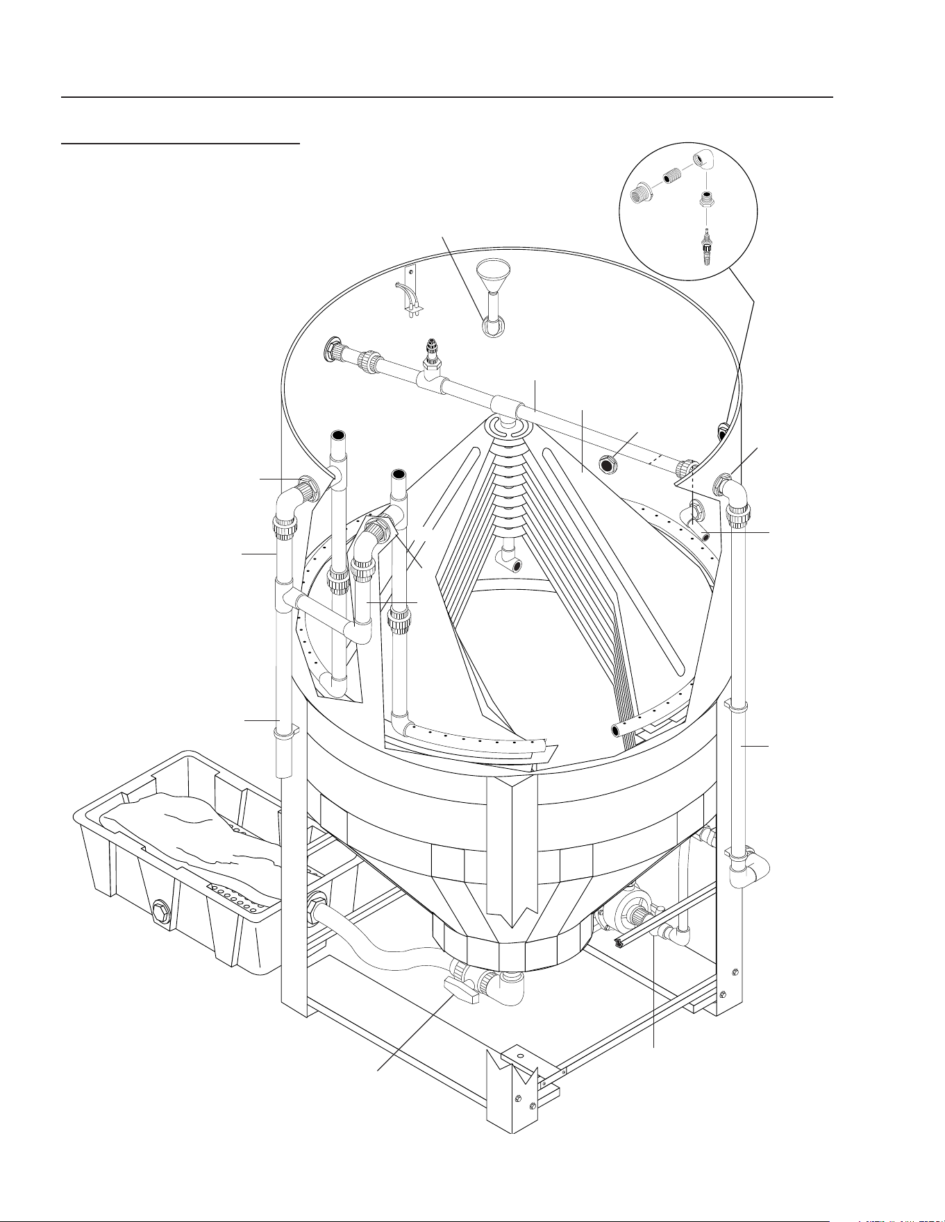
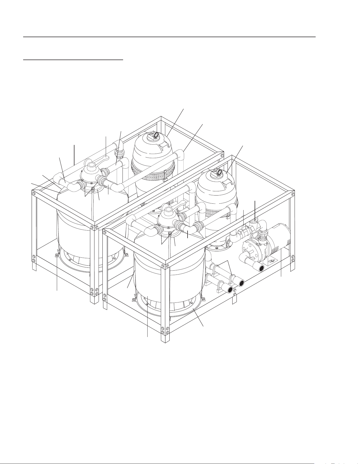
CLARIFIER ASSEMBLY
ALL MODELS
FIGURE 4
A4
P4
B6
Oil
Skimmer
Assembly
A3
To
Ozone
Mix Pump
B5
Coalecsing
Cones
A6
P6
B4
P3
B3
To Vertical
Storage
Tank #1
B1
Valve #2
Valve #5
CLARIFIER SERIES OPERATOR’S MANUAL
11
CL-600 • #8.913-968.0 -C
OPTIONAL FILTER PAC III
8.903-715.0
FIGURE 5
89139680-2
Multi-Media
Filter
Valve #13
Carbon
Filter
Valve #12
Cartridge
Filter
Valve #11
Inlet to Filter
Pac from
Tank #1
Backwash
Line to Pit
Return
from Filter
Pac to
Tank #2

12
CLARIFIER SERIES OPERATOR’S MANUAL
CL-600 • #8.913-968.0 -C
VALVE LOCATION AND
FUNCTION
It is extremely important to know the location and func-
tion of the valves on the Clarifi er. Improper positioning of
the valves can cause overfl ow or damage which could
result in time consuming clean-up and repairs. Study the
section on “Valve Location and Function.”
Valve 1 -- Flow control valve
This valve controls the amount of water allowed into the
Clarifi er from the sump pump. It is also used to control
the volume of water going back to the collection pit for
recycling through the system. (See page 38)
Valves 2 & 3 -- Ozone pump
These valves should be open at all times. NOTE: Only
to be closed when removing the ozone pump. (See
page 38)
Valve 4 -- Oil skimming bucket
This valve should be closed except when draining off
oil. (See page 38)
Valve 5 -- Tank valve
This valve should only be opened when draining sludge.
(See page 38)
Valve 6 -- Rinse water control valve
(CL-603)
This valve is opened only when rinse water is needed.
(See page 32)
Valve 7 -- Outlet to pressure washer valve
(CL-603)
After start-up, this valve is left open all of the time. Con-
trols water to the pressure washer. (See page 32)
Valve 8 -- Rain water overfl ow valve
(CL-603)
This valve is left open partially. When SV1 opens, some
water is allowed to discharge while still providing water
for the pressure washer. (See page 32)
Valve 9 -- Transfer pump valve (CL-603)
Open Fully. Fills tank #2 with fresh water when system
runs low on water. (See page 32)
Valve 10 -- Recycle fl ow control valve
CL603)
This valve is used to control the volume of water going
back to the collection pit for recycling through the system
when the timer activates the solenoid, SV3, for recycling
the system. (See page 34)
Valve 11 -- Filter pack fl ow control valve
(CL-603)
This valve controls the amount of water allowed to fl ow
through the fi lter pack. (See page 12)
Valves 12 & 13 -- Filter control valve (CL-603)
When set on Filter, this valve allows water to pass
through the fi lter. When set on Backwash, the water
passes through the fi lter in reverse, then passes back
to the collection pit. (See page 12)
Filling system with water
Valve 1 -- Open Valve 12 -- Filter
Valve 11 -- Open Valve 13 -- Filter (Filter Pac III)
On initial start-up, or if the system has been drained of
water, it will be necessary to fi ll the system and piping
with fresh water. This is done as follows:
Open valve 1 for CL-600. Open valves 1, 11 and the fi lter
valves 12 and 13 for CL-603.
Make sure the sump is full of water. Adjust the valve posi-
tions as noted above. Turn “ON” the pump to allow water
to fi ll the system. You may have to turn the fl oat override
switch to the “ON” position to start the pump. When the
Clarifi er becomes full, water will fl ow to discharge or the
discharge barrel. When the system is fi lled, turn “OFF”
the fl oat override switch. You may have to turn the pump
switch “OFF” to stop the pump. For the CL-603, the fl oat
controls will automatically fi ll the fi lter pack.
Running
Valve 1 -- Open Valve 12 -- Filter
Valve 7 -- Open Valve 13 -- Filter (Filter Pac III)
Valve 11 -- Open
Adjust valves as shown above. When water begins to fl ow
through the Clarifi er, adjust valve 1 so that fl ow meter
reads 5-30 GPM. Record hours from hour meter and fl ow
rate into operation log. The clarifi er is now operational.
For the CL-603, adjust valve #11 to read 5 - 30 GPM.
Backwash multi-media fi lter CL-603 -
Filter pac III
Valve 1 -- Open Valve 12 -- Backwash
Valve 7 -- Open Valve 13 -- Filter
Valve 11 -- Open
Position valves for backwash as shown above. Turn the
Float Override Switch to the “ON” position to start pump.
Adjust fl ow to 30 GPM using valve 11.
The water is now fl owing in reverse through the multi-
media fi lter taking all the impurities back to the pit. Turn
the fl oat override to the “OFF” position. Return to the
fi ltering mode. Make sure the fl oat override switch is in
the “OFF” position for automatic operation.

CLARIFIER SERIES OPERATOR’S MANUAL
13
CL-600 • #8.913-968.0 -C
Backwash Carbasorb Filter
CL-603 - Filter Pac III
Valve 1 -- Open Valve 12 -- Filter
Valve 7 -- Open Valve 13 -- Backwash
Valve 11 -- Open
Position valves for backwash as shown above. Turn the
fl oat override switch to the “ON” position to start pump.
Adjust the fl ow to 15 GPM using Valve 11.
The water is now fl owing in reverse through the carba-
sorb fi lter taking all the impurities back to the pit. Turn
the fl oat override to the “OFF” position. Return to fi lter
mode. Make sure the fl oat override switch is in the “OFF”
position for automatic operation. NOTE: The carbon is
very light. Using excessive water fl ow will wash the car-
bon out of the fi lter and into the collection pit. If you see
carbon coming out of the fi lter using 15 GPM, lower the
rate of fl ow to 10 GPM.
GENERAL MAINTENANCE
AND SERVICE
Periodic Maintenance:
1. Oil skimmer collection drum:
Monitor the level of oil in the collection drum. Empty
as required.
2. Solids removal:
Settled solids are collected in the bottom of the cone
of the Clarifi er tank. The solids must be removed pe-
riodically as dictated by the dirt load coming into the
machine. The procedure for removal is as follows:
Open valve #5. Fill up the bag, then shut the valve.
Repeat as needed.
3. Check the electrical cords to ensure they are safe,
no damage or cracking.
4. Check inlet and outlet pipes for leaks or damage.
Cartridge Filter:
The cartridge fi lter is a high performance industrial fi lter
manufactured from durable, corrosion-proof materials. It
is designed for continuous or intermittent operation. The
cartridge fi lter utilizes a reusable, reinforced polyester
cartridge fi lter element to provide a high degree of wa-
ter clarity and long fi lter cycles with absolute minimum
care.
Filtering:
Filtration starts as soon as fl ow is steady through the
fi lter. As the cartridge fi lter removes dirt from the water,
the accumulated dirt causes a resistance to fl ow. As a
result, the pressure will rise and the fl ow will decrease.
When the pressure rises 8 - 10 psi above the starting
pressure, or when fl ow decreases below the desired
rate, clean or replace the cartridge fi lters.
Remove/Replace Cartridges:
Removing Cartridge Elements
1. Shut off the pump.
2. Open the drain valve and allow the water to drain
from the fi lter. NOTE: To assist the draining process,
open the air vent a few turns.
3. Disassembly:
a. Unscrew the lock-ring from the top of the fi lter
and lift off.
b. To remove fi lter cover, tap it on the side to break
the seal.
4. To remove cartridge:
a. Grasp the handles on the dirt catcher assembly
and lift out, using a slight rocking motion.
b. Slide the cartridge element off the dirt catcher
assembly.
c. Clean cartridge (see section on Cleaning Car-
tridges).
Reinstalling Cartridges:
1. Flush and drain any dirt or debris from the bottom
of the fi lter tank.
2. Carefully replace the cartridge element back over
the dirt catcher assembly. Make sure “This Side Up”
is visible on cartridge element.
3. Replace the cartridge element and the dirt catcher
back in the fi lter tank, making sure the dirt catcher
assembly is fully seated.
4. Make sure the fi lter head fl anged sealing surface is
clean and the o-ring is in place. NOTE: The o-ring
will need to be lubricated periodically.
5. Replace the filter cover, making sure it is fully
seated.
6. Replace the lock-ring and secure hand tight.
7. Close the drain valve, set valves and follow instruc-
tions for “Filling System with Water”.

14
CLARIFIER SERIES OPERATOR’S MANUAL
CL-600 • #8.913-968.0 -C
Cleaning Cartridges:
The cartridge fi lter element can be cleaned by pressure
washing inside and out with no more than 1000 psi of
pressure, or use a garden hose. For best results after
hosing the cartridge, allow it to dry and carefully brush
pleated surface areas to remove fi ne particles.
Algae, dirt and oils can form a coating on the cartridge
pleats which may not be thoroughly removed by hosing.
To remove such materials, soak the cartridge in a solu-
tion of fi lter element cleaner (available from your dealer).
Follow directions for use and allow an hour for soaking.
Hose cartridge thoroughly before reinstalling in fi lter.
If calcium or mineral deposits are excessive, the cartridge
may be restored to “like new” condition by soaking in mu-
riatic acid. Use commercially available 20% muriatic acid
added to water in a 1 to 1 ratio. Use a plastic container
and take extreme care when handling cleaning agents
as they are harmful to eyes, skin and clothing.
Safety glasses and protective gloves must be worn
during this cleaning operation. After cleaning, fl ush
with water. NOTE: SEE ITEM 6 UNDER SAFETY IN-
STRUCTIONS.
A spare “standby” cartridge fi lter element is an excel-
lent investment. It provides convenience and assures
that your fi lter will always be ready to operate at peak
effi ciency. For best results, use only genuine WATER
MAZE cartridges in your fi lter.
Winterizing:
If a heated area is not provided in areas where subfreez-
ing temperatures can be expected, the entire machine
must be drained.
Testing Carbon:
Remove the valve from the carbasorb fi lter and extract
a carbon sample. Place carbon sample in a 4 oz. plastic
bottle. (Fill the bottle 1/4 full of carbon, about 1 inch.)
Fill the 2 oz. bottle with water and add 1 drop of chlorine.
Dip the chlorine test paper into the solution to ensure
you have at least 100 parts per million of chlorine in
the mixture. Add this solution to the carbon in the 4 oz.
bottle. Cap and shake it periodically over a period of
three minutes. After three minutes, dip a new piece of
chlorine test paper into the solution. Compare the color
with the color chart that comes with the test paper. If you
get a reading, order new carbon. There may be some
dark discoloration from the carbon. Do not confuse
this with the color caused by the chlorine.
CHEMICAL MAINTENANCE
PROGRAM
Owner chemical maintenance program to
maintain recycled water quality:
Daily monitoring and adjustment of WATER MAZE
recycled water chemistry is essential. If not monitored
and controlled, recycled water will become chemically
unbalanced resulting in a host of problems such as algae
and bacteria growth, obnoxious odors, iron discoloration
and ultimately it will be unfi t for reuse and must be dis-
posed of.
The daily monitoring and adjustment maintenance pro-
gram presented herein will, if followed, provide suitable
recyclable wash water. The proper maintenance of the
water is not complicated and depends upon a few basic
principles which are:
1. Physical - effective fi ltration and recirculation of
the water
Effective recirculation of the water through the catch
basin, and the Clarifi er is achieved only if the system
is utilized often (daily 6-8 hours or more) or if the
system is set to recirculate the water throughout
the total system. The Clarifi er has the controls and
procedures to achieve continuous effective water
recirculation throughout the process. Therefore, if
the Clarifi er is operated properly, it will achieve the
required need of effective fi ltration and recircula-
tion.
2. Chemical - proper adjustment of alkalinity
and pH
The most important factor to control and maintain
is the pH of the water (i.e. the acidity or alkalinity). If
the recycled water is acidic (low pH) it will dissolve
iron into solution. The presence of iron of more
than 0.2 ppm will result in rusty staining of virtually
anything the water comes in contact with. Alkaline
water can cause cloudiness and greatly reduces the
effectiveness of chlorination. Many of the cleaning
detergents are alkaline and will make the recycled
water too alkaline. Also, high alkaline water is diffi cult
to fi lter and decreases fi lter media life. The proper
pH range to maintain is 6.8 - 7.2.
Alkalinity refers to the soluble salts in the water.
These include bicarbonates, carbonates, hydroxides
and other alkali compounds. The waters total alkalin-
ity controls its resistance (buffering ability) to large
fl uctuations in pH levels.
Another factor which should be monitored for proper
water chemistry balancing is calcium hardness.
The presence of too much calcium can lead to the
formulation of scale in the fi lters.

CLARIFIER SERIES OPERATOR’S MANUAL
15
CL-600 • #8.913-968.0 -C
3. Biological - adequate disinfection, algae, bacte-
ria, and odor control
Chlorination and ozonization are used to control
bacteria, odor and algae formation. For chlorine to
be effective, it must be available as free chlorine. If
the proper pH and alkalinity is not maintained, or if
the water contains dirt particles, the chlorine will be
combined chlorine and not be effective in the control
of algae and bacteria growth. Combined chlorine has
only 1/15th the strength of free chlorine. Ozoniza-
tion is used in the Clarifi er system. Chlorine can be
added to help with control if needed.
The killing of bacteria by chlorine exists in two
phases:
1. The penetration of the active germicidal principal
(hypochlorous acid) into the bacterial cell.
2. The chemical combination of this ingredient with
the protoplasm (the complex composition which
forms the essential part of plant and animal
cells). This combining is directly responsible for
the death of the organism.
The activity of this germicidal effect is reduced in
alkaline solutions (those with a pH greater than 7.5)
and expressed as follows:
pH % of Effectiveness
4.0 100.0
5.0 99.6
6.0 95.8
7.0 69.7
8.0 18.7
9.0 2.2
10.0 0.2
Hypochlorite when added to solutions with a pH
lower than 6.0 can produce oxide which is toxic. In
vehicle washing, almost all cleaning compounds
are alkaline in nature. Hypochlorite will still control
bacterial growth and thus smell at higher alkaline
ranges, but as the table indicates, its effectiveness
is reduced.
To compensate for this inhibited activity, a larger
quantity of hypochlorite is used. This will control bac-
terial growth but will increase operational costs.
Typical hypochlorite has a pH of approximately 11.6.
This high pH will only increase the pH of holding tank
water making pH adjustment more diffi cult.
Trichloro-S-Triazine Trione is a chlorine compound
which has a pH of 3.0 and when added to holding
tanks will aid in the reduction of tank pH levels.
Unlike hypochlorite, which is usually 15% chlorine
and will produce sodium or calcium salts in holding
tanks, these new products are 99% chlorine which
means that if a solid “puck” of chlorine is used, the
total effectiveness of the puck is superior to that of
hypochlorite and no negative by-products are pro-
duced.
DAILY CHEMICAL
MAINTENANCE
Step 1. Collect a water sample from storage tank #1.
NOTE: Be sure that the water is circulating from the
sump through the Clarifi er system and back to the catch
basin.
Step 2. Using the test strips supplied, measure:
A. The pH.
B. The total chlorine (if using chlorine).
C. The free chlorine (if using chlorine).
D. The alkalinity (if needed).
E. The calcium hardness (if needed).
Step 3. If the pH is 6.8-7.2 go to Step 4, if not, adjust
the pH in the water being recycled between the oil water
separator and the pit to pH 6.8-7.2. Muriatic acid or liquid
Alum can be used to lower the pH. Soda ash (sodium
carbonate) or caustic soda (sodium hydroxide) can be
used to raise the pH.
Adjust the pH gradually allowing complete mixing af-
ter adding chemical. Take a new sample, read the pH
and continue to adjust gradually until the desired pH is
achieved.
Step 4. The total alkalinity should be between 50-150
ppm. If the total alkalinity is too low add sodium bicarbon-
ate to raise it. If total alkalinity is too high, add muriatic
acid to bring it within acceptable range. This will also
decrease the pH. If the pH goes below 7.0, add sodium
bicarbonate to increase the pH. This procedure may have
to be repeated several times to get the pH and a total
alkalinity into the proper range.
Step 5. The calcium hardness should not exceed 25
grains. If it is too high, some water must be removed from
the system and fresh makeup water added. Alternatively,
an ion exchange water softener or an ionizer may have
to be added to the system to reduce and maintain lower
calcium hardness levels.
Step 6. Free chlorine levels should be 1-2 ppm if chlo-
rine is added for additional control. A 10-15% concen-
trated liquid chlorine is available at pool supply outlets.
Household bleach can be used, but contains only 5%
chlorine. Chlorine continually dissipates and becomes
used up and the chlorine level must be adjusted daily.
Remember chlorine is most effective when the pH level
is correct (6.8-7.2).
Initially, in order to achieve proper water chemistry bal-
ance, extra time is needed. However, once achieved, it
can be easily maintained in a minimum amount of time
by daily monitoring and adjustment.
16
CLARIFIER SERIES OPERATOR’S MANUAL
CL-600 • #8.913-968.0 -C
ULTRAVIOLET LIGHT
COMPLIANCE
Ultraviolet Light Safety Requirements
The device used in this product is a Class 1 certifi ed
ozone generator product. Operating this product outside
specifi cations or altering its original design may result
in hazardous radiation exposure, and may be considered
an act of modifying or new manufacturing of a laser
product under U.S. regulations contained in 21CFR
Chapter 1, subchapter J.
CAUTION: Avoid exposure to direct or
strongly refl ected germicidal ultraviolet rays.
DO NOT STARE INTO BEAM.
DANGER: Ultraviolet radiation. Disconnect
Power Before Replacing Lamp.
DANGER: Connect only to a circuit that is
protected by Ground Fault Circuit Interrupt
(GFCI).
PUMP OPERATION
(Ozone, fi lter, or transfer)
WARNING: Do not touch pumps, pump motors, water
or discharge piping when the pumps are connected
to electrical power. Do not handle a pump or pump
motor with wet hands or when standing on a wet or
damp surface or in water. Never touch a pump or
discharge piping when a machine is operating or
fails to operate. Always disconnect the pump cord
(power) before handling.
1. The shaft seal depends on water for lubrication. Do
not operate the pump unless there is water. Dry
running (pump not pumping water) will cause seal
damage and eventual pump failure.
2. The motor on single phase machines is equipped
with an automatic reset thermal protector. This
means if the temperature in the motor should rise
unduly, the switch will cut off all power before dam-
age can be done to the motor. When the motor has
cooled suffi ciently, the switch will reset automatically
and restart the motor. If the protector trips repeatedly
(cycling on protector) the pump should be removed
and checked as to the cause of the diffi culty. Low
voltage, long extension cords, clogged impeller, very
low head or lift, etc., could cause cycling. Cycling of
the protector will cause eventual motor burnout.
PUMP MAINTENANCE
(Sump)
WARNING: Before attempting to service, discon-
nect power from machine. Do not handle the pump
with wet hands or when standing on a wet or damp
surface or in water. Failure to follow precautions can
result in personal injury and /or property damage.
NOTE: Only qualifi ed electricians or servicemen should
attempt to repair this machine. Improper repair and/or
assembly can cause an electrical shock hazard.
1. Bearings in this machine are pre-lubricated. No ad-
ditional lubrication is necessary.
2. Cleaning - occasionally clean the sump pit and pump
if dirt or foreign matter accumulates. Small stones,
gravel, sand, dirt, silt, etc. can clog and damage
the pump and pump seal, eventually causing pump
failure.
3. Disassembly of the motor prior to expiration of the
warranty will void the warranty. It may also cause
internal leakage and damage to the machine. If re-
pairs are required, return the pump to a local service
station.
4. If the motor has been disassembled or the switch
chamber opened after the warranty expiration date,
the O-rings and gaskets must be replaced. Care
must be taken to assure that the seals, the switch
cover and the air tube gaskets do not leak.
5. The pump should be checked for proper operation
weekly or monthly by watching the operation of the
pump. If anything has changed since the pump was
new, the pump should be examined, and repaired if
necessary.
OZONE GENERATOR
Ozone...Nature’s Purifi cation Agent:
Ozone is produced in nature or artifi cially by man. In
the earth’s atmosphere, ozone is formed when oxygen
is exposed to ultraviolet light or an electrical charge as
during thunderstorms. Ozone’s primary function in na-
ture is to purify the air we breathe and screen us from
harmful rays of the sun. In a similar fashion, the Clarifi er
system uses ozone to disinfect water because ozone
has a number of characteristics that make it ideal for
water treatment.

CLARIFIER SERIES OPERATOR’S MANUAL
17
CL-600 • #8.913-968.0 -C
How the Clarifi er Ozone System Works:
Because ozone is unstable, it cannot be packaged and
used at a later date. For this reason, ozone is always
produced where it is utilized.
Point-of-use ozone generation is simple. This powerful
disinfectant is produced from ambient air surrounding the
generator using special ultraviolet lamps located inside
the system’s cabinet. To generate the ozone, air move-
ment is created through the use of an air compressor or
water venturi. As air passes over these unique lamps,
the oxygen contained in the air is converted. The result-
ing ozone gas is subsequently introduced to the water
in the inlet pipeline, where oxidation and disinfection
immediately takes place.
Ozone Generator Maintenance:
Caution: Never look at the unshielded ozone lamp
while operating the machine. This lamp can cause
severe eye and skin damage. The indicator light
will be a dim green or not lit at all when operating
properly. The light goes a bright green when there
is a failure. See product description for location of
the indicator light.
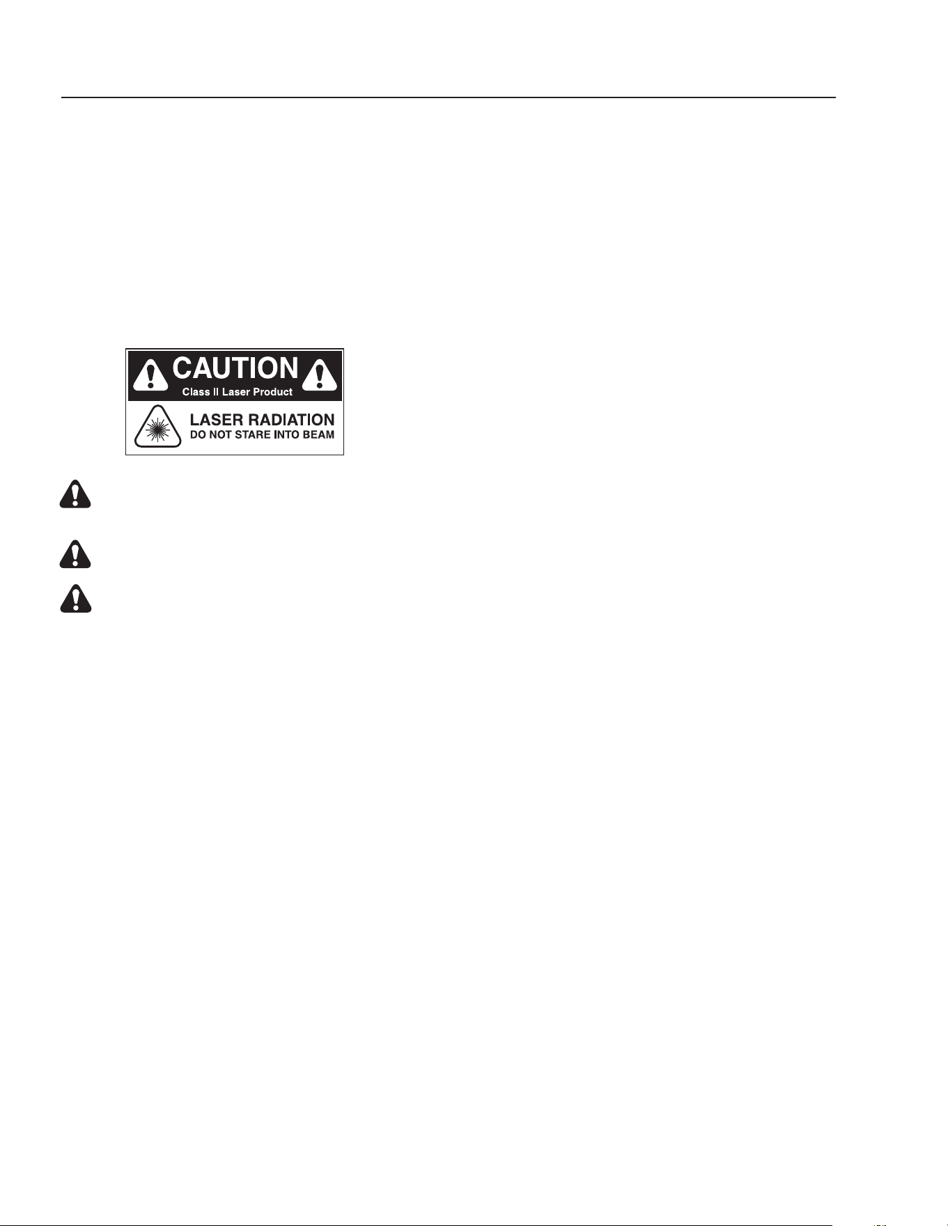
Testing the lamp:
To test the ozone lamp, use a voltmeter set on ohms.
First remove the ozone cover and unplug the lamp plug
from the ozone lamp. NOTE: There are two fi laments
- an upper and a lower - inside the lamp. Place one of
the voltmeter leads on one of the lamp prongs and, with
the other lead, touch all of the three remaining prongs.
If continuity is not achieved on both upper and lower
fi laments, replace the ozone lamp (Part #6-0534) (See
fi gures 7 & 8).
To test the power pack, use a voltmeter set on the cor-
rect voltage (120V or 240V). Place one of the voltmeter
leads into the lamp plug where the white wire goes into
it and plug the other voltmeter lead into the lamp plug
where the blue wire goes into it. If no voltage is present
replace the ozone ballast (Part #6-05231 - 120V, Part
#6-05232 - 240V). When ordering an ozone ballast, you
also need the 4-pin connector (Part #6-05233).
Replacing the lamp:
Lamp replacements are available from your WATER
MAZE Dealer should they need to be replaced. Simply
turn off the power to the Clarifi er at the breaker, remove
the screws on the power pack cover and remove the
cover. Disconnect the plug on the end of the ozone lamp.
Now, loosen the lamp holder locking ring from around
the end of the lamp by turning it counterclockwise and
remove it. Remove the lamp by grabbing the rubber bush-
ing around the end of the lamp and pulling it straight out.
Remove the rubber bushing from the lamp and install
it on your new lamp, making sure the outer edge of the
bushing is fl ush with the outer edge of the silver end cap
on the lamp. Now, slide the lamp back into the reaction
chamber. The lamp holder may now be reinstalled and
tightened. Reinstall the plug onto the lamp and replace
the power pack cover. Caution: Keep the lamp free of
fi ngerprints and dust particles by only handling the metal
end caps on the lamp. You can clean the lamp with rub-
bing alcohol and a soft cloth. A dirty lamp will not allow
maximum ozone output.
Specifi cations:
Energy required 110V: 105VAC MIN., 125VAC MAX.,
.800 AMP/Ballast
Energy required 220V: 210VAC MIN., 230V MAX.,
.450AMP/Ballast
Power consumption: 20 Watts
Average lamp life: 9,000 Hours
Lamp wavelength: 185 nm
18
CLARIFIER SERIES OPERATOR’S MANUAL
CL-600 • #8.913-968.0 -C
OZONE GENERATOR TESTING
FIGURE 7
Four Pin Connector
Ozone Lamp Prongs
Ballast
CLARIFIER SERIES OPERATOR’S MANUAL
19
CL-600 • #8.913-968.0 -C
OZONE GENERATOR
DISCONNECT F
R
OM ELECTRICAL
SUPP
L
Y BEFORE SE
R
VICING.
DESCONECTE LA CORRIENTE ELECTRICA
ANTES DE D
AR SE
R
VICI
O
.
COUPER
L
’ALIMEN
TA
TION ÉLECTRI
Q
UE
AV
ANT DE
FAIRE UNE RÉ
P
AR
A
TION.
DISCONNECT F
R
OM ELECTRICAL
SUPP
L
Y BEFORE SE
R
VICING.
DESCONECTE LA CORRIENTE ELECTRICA
ANTES DE D
AR SER
VICI
O
.
COUPER
L
’ALIMEN
TA
TION ÉLECTRI
Q
UE
AV
ANT DE FAIRE UNE RÉPAR
A
TION.
INDICATOR
L
IGHT OPERAT
I
ON
A b
r
ight contin
uous light indicates UV
light or ballast de
f
ecti
v
e
.
Una luz luminosa indica que la luz ult
r
a-
violeta o t
r
ans
f
o
rmador está de
f
ectuos
o
.
Une lumière claire indique que la lumière
ult
r
a
violette ou le t
r
ansf
o
rmateur est
déf
ectueux.
OPER
A
CION DE LA LUZ
INDICADORA
OPÉR
A
TION DE LE LAMPE
INDIC
A
TEUR
H
O
T!
CALIENTE!
CHA
UD!
CA
UTION
PRECAUCION
A
TTENTION
8.900-455.0
!
W
ARNING!
A
T
ENCIO
N
!
/A
TT
ENT
I
ON
!
!
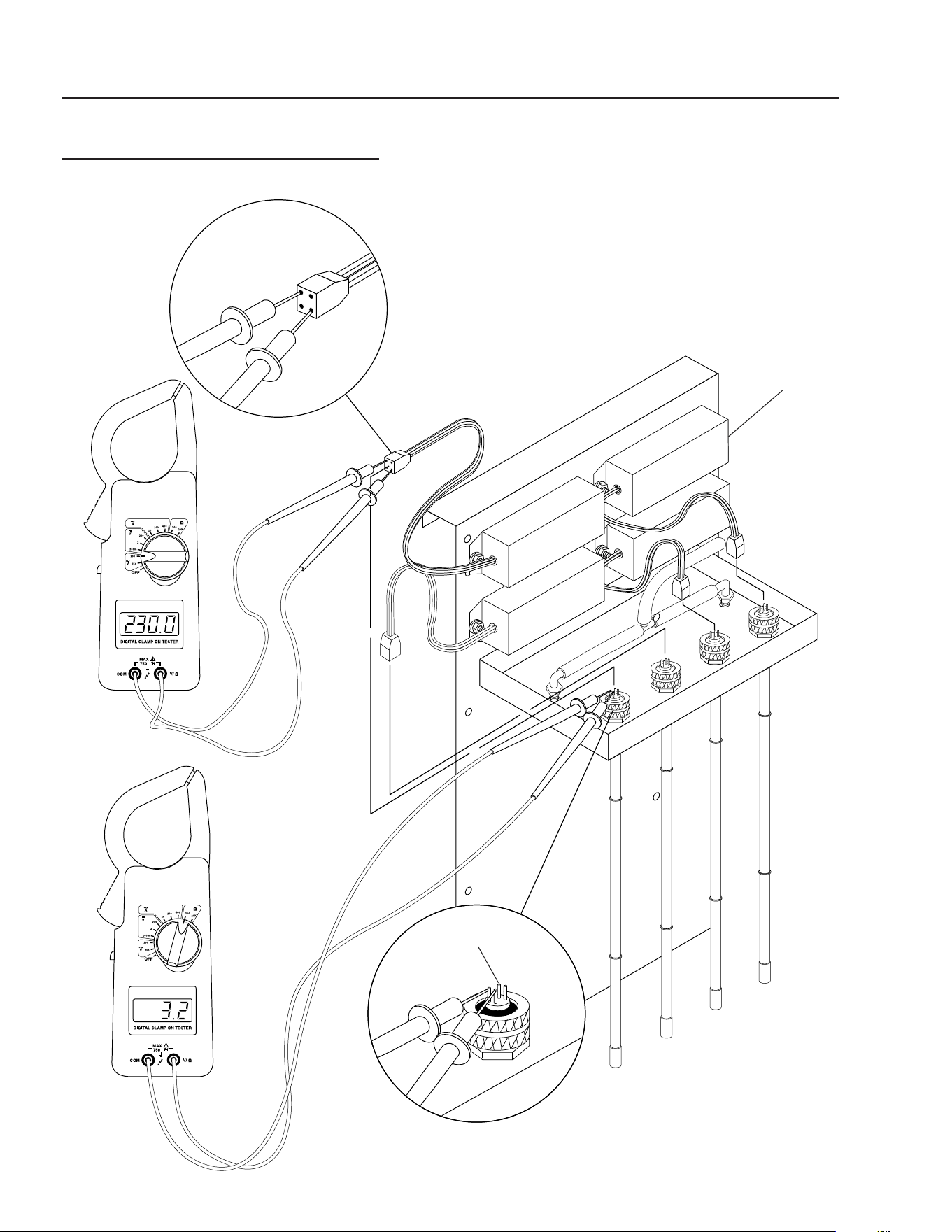
89139680-5
OZONE GENERATOR
SERIES 400 BREAKDOWN
FIGURE 8
Ballast
Ozone Lamp
Ozone
Check Valve
Four Pin
Connector
ON/OFF
Switch
Green
Indicator
Light
20
CLARIFIER SERIES OPERATOR’S MANUAL
CL-600 • #8.913-968.0 -C
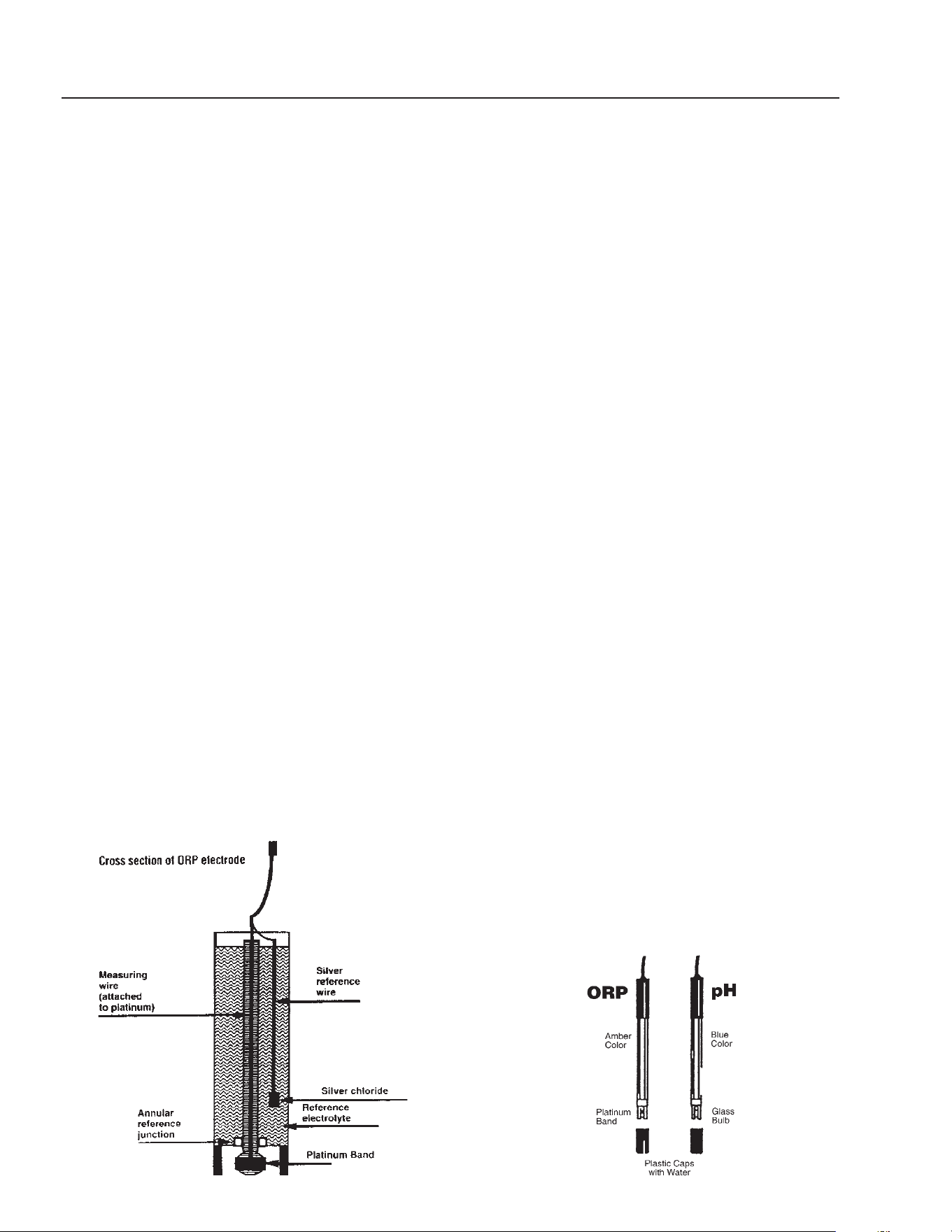
ORP MEASUREMENT SYSTEM
NOTE: This system is optional on Clarifi er machines.
Measuring ORP is similar to measuring pH. Platinum is
sensitive to electron activity in the same manner as pH
sensitive glass is sensitive to the presence of (activity)
the hydrogen ion. In a typical ORP sensor, the electrode
is nearly identical to the pH electrode, with the platinum
surface (usually a platinum rod or band) serving as the
measuring half of the electrode and a silver/silver chlo-
ride reference wire in a potassium chloride (KCl) refer-
ence electrolyte serving as the reference half. Several
manufacturers offer ORP sensors.
The electrode can be compared to a battery, where
voltage fl ows from the measuring side to the reference
side. The reference electrolyte completes the circuit by
providing an electrical connection back to the solution
being measured. For this reason, the reference junction
must remain clean and free fl owing.
Care of the ORP electrode also mimics that of pH in-
strumentation. For instance, the electrode must remain
in the solution at all times and the system will require
routine cleaning and calibration to compensate for
electrode degradation. It is likely that the electrode will
require replacement every one to two years, depending
on the application.
Cleaning the ORP electrode is best done with a fi ve
percent hydrochloric acid solution. This solution is most
effective for solubilizing hard-water deposits that may
occur in the reference junction free fl owing to enable
the reference electrolyte to carry the reference voltage
back to the solution.
Calibration should be a regular maintenance task.
Monthly calculation is typical in many disinfection situa-
tions. Calibration is best accomplished in freshly made
solutions of quinhydrone saturated into pH 4.0 and 7.0
buffer solutions. Quinhydrone is a weak reducing agent
whose activity changes with pH. By adding it to solutions
of known pH, standard ORP solutions of 87 millivolt (mV)
(7.0 pH) and 264 mV (4.0 pH) can be produced. These
solutions are used to monitor the offset (standard) and
space (slope) of the electrode as it degrades over time.
Quinhydrone should be stored cool, and fresh solutions
employed for each calibration.
ORP/pH Meter Installation:
1. On a Clarifi er 600, you will need to mount a 230 to
24 volt step-down transformer and run wires from
terminals N & 2 to the 230 volt side. Then connect
wires from the 24 volt side to the ORP/pH controller
terminals 1 & 2 marked power.
2. Mount the metering pumps to the Clarifi er and con-
nect electrical wires to designated controller termi-
nals. On other Clarifi er models, attach wires from
the 24 volt step-down transformer to the ORP/pH
controller terminals 1 & 2 marked power.
3. For further information read the ORP/pH manual.
ORP and pH Sensors:
How should I clean the sensors?
The cleaning of the ORP/pH sensors must be done on
a weekly maintenance schedule if used in a moderate
to heavy oil and dirt load; on a monthly maintenance
schedule if used in a low oil or dirt level.
To clean the sensors, do the following: Loosen the sen-
sor from the compression tee. With a Q-Tip and any
household degreaser (i.e. 409) spray and wipe the sen-
sor probe clean. Rinse with clean water. Dip the sensors
in muriatic acid to remove hard water deposits. Rinse
with clean water.
To check sensor for proper operation, place a small
amount of white vinegar, muriatic or hydrochloric acid
into a cup and place sensor probe into solution. For
the pH sensor, fl ip controller switch to pH reading. The
needle should drop. For the ORP sensor, fl ip controller
switch to ORP reading. The needle should rise.
NOTE: Only clean one sensor at a time. Sensors must
stay in some kind of liquid at all times.
CLARIFIER SERIES OPERATOR’S MANUAL
21
CL-600 • #8.913-968.0 -C
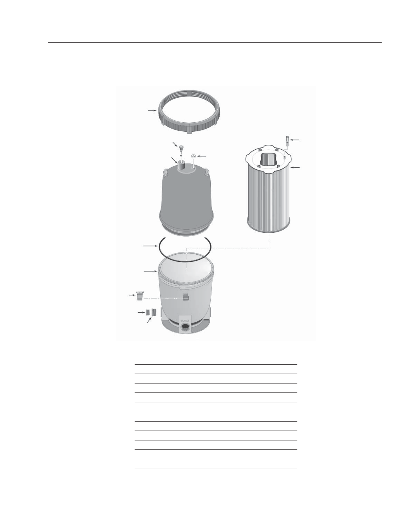
CARTRIDGE FILTER EXPLODED VIEW AND PARTS LIST
FILTER PAC III • 8.723-206.0 • PLM 300
ITEM PART NO. DESCRIPTION QTY
1 8.750-004.0 Posi-Lok™ Ring 1
2 8.750-005.0 Air Release Valve Assy 1
3 NA Tank Shell, Upper Half 1
4 8.750-006.0 Cord-O-Ring 1
5 NA Tank Shell Lower Half 1
6 NA Safety Latch for Ring 1
7 NA 1-1/2" NPT Plug 1
8 NA Adapter Fitting 1
9 8.750-007.0 Pressure Gauge 1
10 NA Air Bleed Assembly 1
11 NA Filter Module 1
1
3
5
7
9
11
2
4
6
8
10
22
CLARIFIER SERIES OPERATOR’S MANUAL
CL-600 • #8.913-968.0 -C
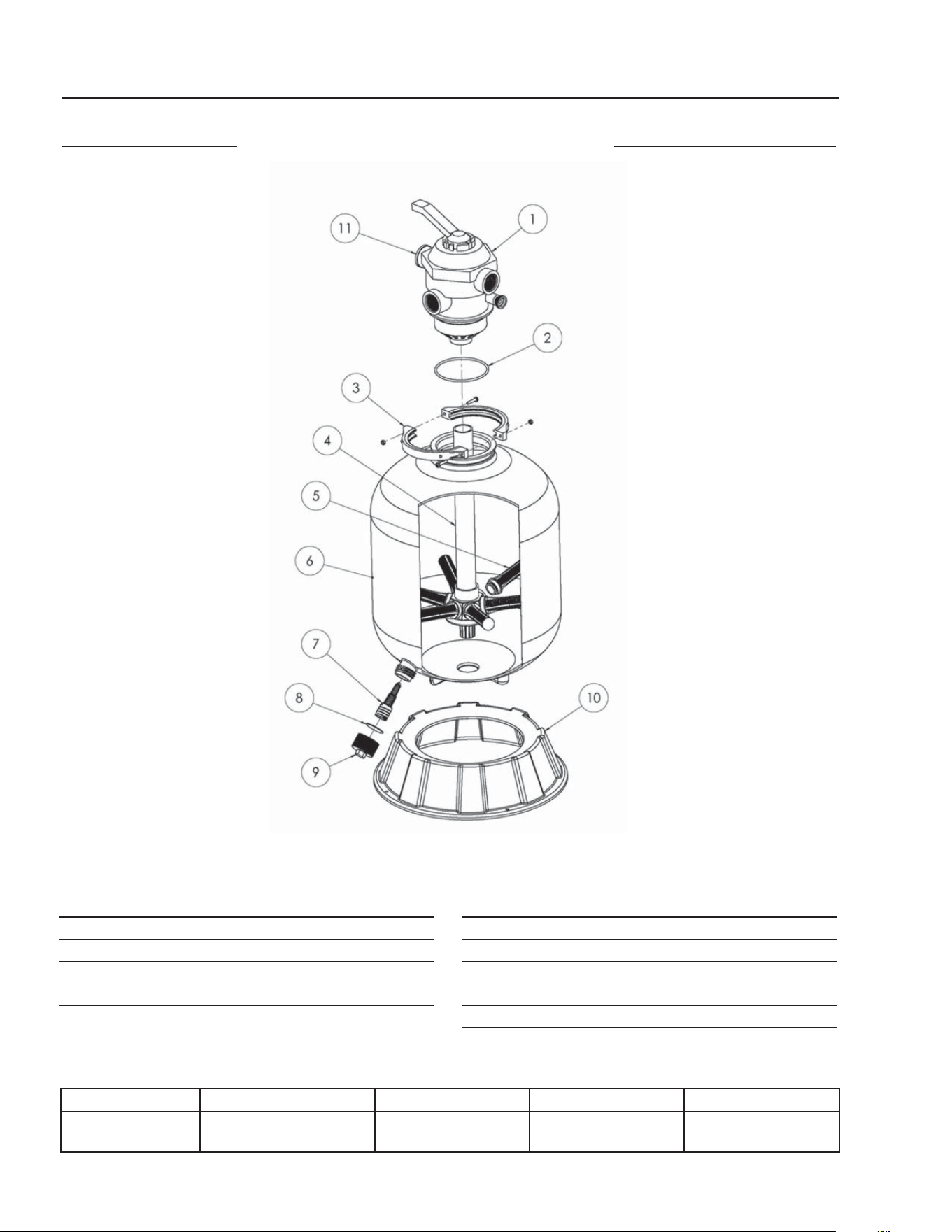
CARBON FILTER
FILTER PAC III
8.726-028.0
MULTI-MEDIA FILTER
FILTER PAC III
8.726-028.0
ITEM PART NO. DESCRIPTION QTY
1 8.726-030.0 Multiport Valve, Top Mount 1
2 NA O-Ring, Valve Body 1
3 NA Clamp Assembly 1
4 NA Piping Assembly 1
5 NA Lateral 8
6 NA Filter Tank w/Drain 1
ITEM PART NO. DESCRIPTION QTY
7 NA Drain Lateral 1
8 NA Gasket, Drain Cap 1
9 NA Drain Cap 1
10 NA Pedestal 1
11 NA Pressure Gauge 1
Tank Diameter Max. Working Pressure Vert. Clearance Max. Water Temp Valve
24" 40 PSI 58" 95°F 6 Position
1-1/2" FPT/MBT
CLARIFIER SERIES OPERATOR’S MANUAL
23
CL-600 • #8.913-968.0 -C
2
5
8
11
14
3
6
9
12
15
1
4
7
10
13
16
17
2
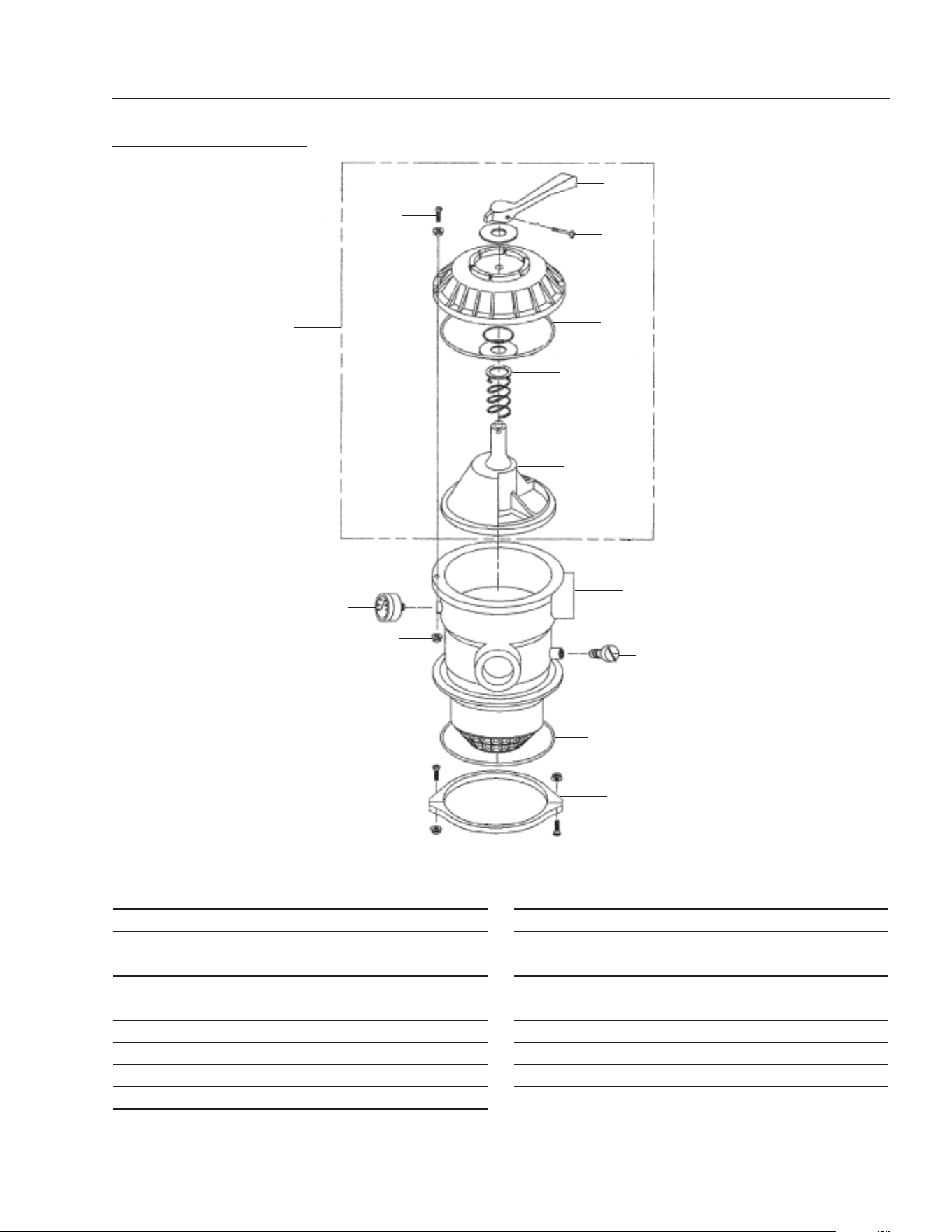
6 POSITION VALVE
1-1/2" PORTS
8.726-030.0
ITEM PART NO. DESCRIPTION QTY
1 NA Handle 1
2 NA Washer, Plastic 2
3 NA Screw, Handle 1
4 NA Valve Top, Black 1
5 NA O-Ring Diverter Shaft 1
6 NA O-Ring 1
7 NA Spring 1
8 NA Diverter w/Gasket 1
9 NA Screw, #10-24 1
ITEM PART NO. DESCRIPTION QTY
10 NA Washer 6
11 NA Nut, #10-24 6
12 NA Valve Body w/Diff - Clamp Style 1
13 NA Air Bleeder w/ O-Ring 1
14 NA O-Ring 1
15 NA Clamp Assembly (See note) 1
16 NA Pressure Gauge 1
17 NA Valve Top Assy (items 1-8) 1
Note: Clamp halves, nuts and bolts sold only in Assembly
24
CLARIFIER SERIES OPERATOR’S MANUAL
CL-600 • #8.913-968.0 -C
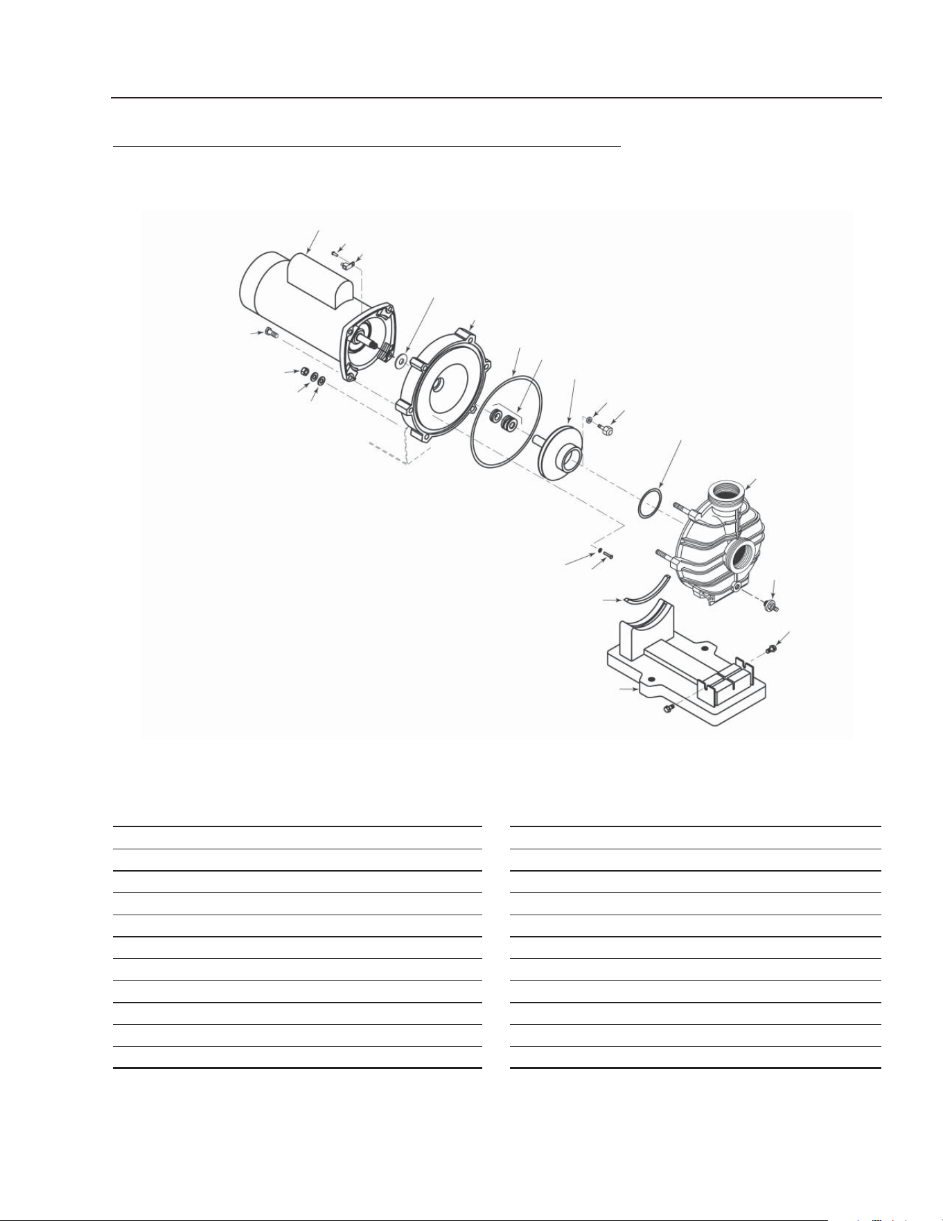
TRANSFER PUMP • CL603B, CL603C
230V 3 PH
460V 3PH
#8.715-404.0 • 2 HP
ITEM PART NO. DESCRIPTION QTY
1 NA Washer 1
2 NA Base 1
3 8.718-524.0 Seal, 1 PH 1
8.718-523.0 Seal, 3 PH 1
4 8.718-535.0 5-5" Impeller 1
5 NA Washer 1
6 NA Nut 1
7 NA Head 1
8 NA Motor 1
1
2
3
4
5
6
7
8
TRANSFER PUMP • CL603A
230V 1 PH
#8.715-402.0 • 2 HP
BRAND MODEL NO.
SIZE
INLET OUTLET AMPS VOLTS PHASE MAX GPM PSI
Scot 60 1-1/2" 1-1/4" 12.7, 3.4 230, 460 1, 3 50 50
CLARIFIER SERIES OPERATOR’S MANUAL
25
CL-600 • #8.913-968.0 -C
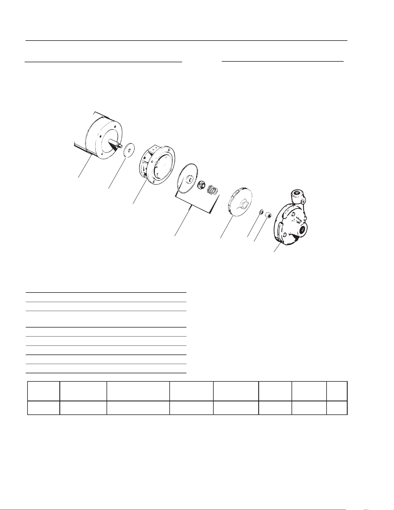
ITEM PART NO. DESCRIPTION QTY
1 8.726-026.0 Motor, 3/4 HP, 230V (CL603A) 1
8.726-025.0 Motor, 3/4 HP, 115V (CL600D) 1
2 NA Slinger 1
3 8.726-024.0 Pump, 3/4 HP, Wet End 1
4 NA Drain Plug 1
5 NA O-Ring, Drain Plug 1
HP Volts Phase
Size
Inlet Outlet
Running
Amps
Max.
Pressure
Max.
Water Temp.
3/4 230V 1 1-1/2" FPT/ 1-1/2"FPT/
1-1/2" MBT 1-1/2" MBT
5.7 40 PSI 104°F/40°C
3/4 115V 1 1-1/2" FPT/ 1-1/2"FPT/
1-1/2" MBT 1-1/2" MBT
10.0 40 PSI 104°F/40°C
ITEM PART NO. DESCRIPTION QTY
6 NA O-Ring 1
7 NA Adapter, Union 1-1/2" Slip 1
8 NA Collar, Union 1
Kit:
6-8 8.750-270.0 Fitting, Compression, 1-1/2" Slip
40
20
0
20 40 60 80
U.S. GALLONS PER MINUTE
TOTAL HEAD IN FEET
1
2
3
4
5
6
7
8
Not Included
With Pump
OZONE PUMP EXPLODED VIEW AND PARTS LIST
CL603A
8.917-760.0 • 230/V • 1 PH
CL600D
8.917-759.0 • 115/V • 1 PH
26
CLARIFIER SERIES OPERATOR’S MANUAL
CL-600 • #8.913-968.0 -C
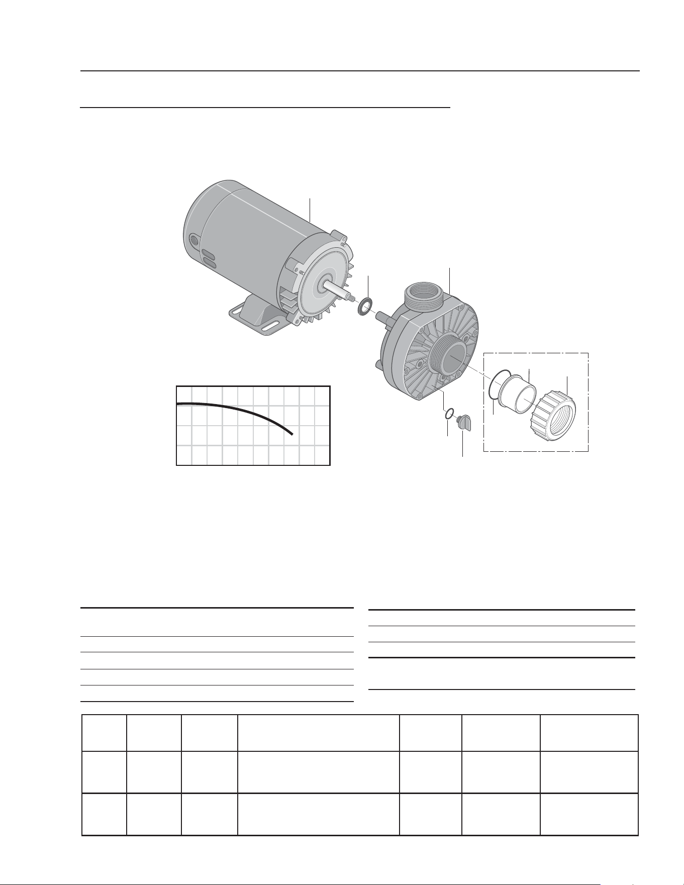
OZONE PUMP EXPLODED VIEW AND PARTS LIST
CL603B, CL603C
8.723-219.0 • 230/460V • 3 PH
ITEM PART NO. DESCRIPTION QTY
1 NA Motor, 3/4 HP 1
2 NA Bracket, Aluminum 1
3 NA Bolt, 304L SS 4
4 NA Casing Cover, 304L SS 1
5 8.750-017.0 Mechanical Seal 1
6 NA O-Ring, Viton 1
7 NA Impeller, 4.12", 304L SS 1
BRAND MODEL NO.
SIZE
INLET OUTLET AMPS VOLTS PHASE GPM / PSI
Ebara ACDU 70 1-1/4" 1" 3.2-3/1.5 208-230/460 3 See Chart
1
8
3
4
5
6
7
2
9
11
12
13
10
14
0 10 20 30 40
90
80
70
60
50
40
30
20
FT
TOTAL HEAD
T.D.H
ITEM PART NO. DESCRIPTION QTY
8 NA Impeller Nut, 304L SS 1
9 NA Casing, 304L SS 1
10 NA Washer, Aluminum 2
11 NA Plug, 304L SS 2
12 NA Washer, 304L SS 8
13 NA Bolt, 304L SS 8
14 NA Casing Ring, Viton 1
CLARIFIER SERIES OPERATOR’S MANUAL
27
CL-600 • #8.913-968.0 -C
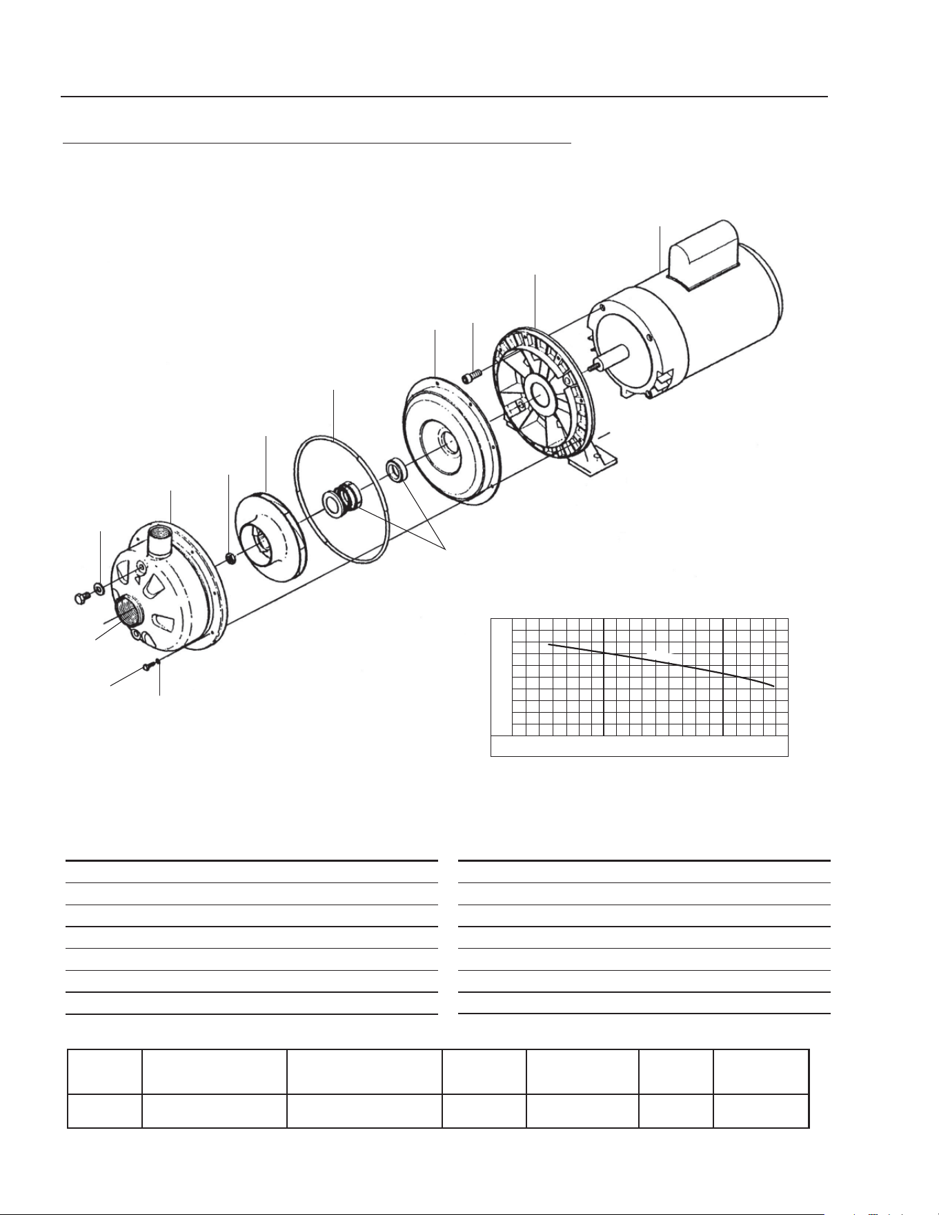
FILTER PUMP EXPLODED VIEW AND PARTS LIST
FILTER PAC III
#8.723-198.0
ITEM PART NO. DESCRIPTION QTY
1 NA Motor 1
2 NA Screw, #10-32" x 1/2" 1
3 NA Bonding Lug 1
4 NA Slinger 1
5 NA Seal Plate 1
6 8.749-301.0 Seal Plate Cord Ring 1
7 8.749-351.0 Shaft Seal 1
8 8.749-345.0 Impeller 1
9A NA Impeller Lock Screw Gasket 1
9B NA Impeller Lock Screw 1
11 8.749-350.0 Diffuser O-Ring 1
ITEM PART NO. DESCRIPTION QTY
12 NA Pump Body (Only) 1
13 NA Drain Plug 1
14 NA Hi-Lo Screw 5/16" - 14 x 5/8" 2
15 NA Base, Corrosion Resistant 1
16 NA Motor Pad for Base 1
17 NA Screw, #8-32" x 7/8" Rd Hd 7
18 NA Lock Washer, #8 Ext Tooth 7
19 NA Flat Washer, 3/8" 6
20 NA Lock Washer, 3/8" 6
21 NA Nut, 3/8" - 16 Hex 6
22 NA Cap Screws, 3/8"-16 x 1" Hex 4
1
2
3
4
5
6
7
8
9A
9B
11
12
13
14
15
16
17
18
19
20
21
22
28
CLARIFIER SERIES OPERATOR’S MANUAL
CL-600 • #8.913-968.0 -C
CLARIFIER WATER PANEL
CLARIFIER CL-603
10
5
3
3
4
4
10
2
3
1
SV2 Solenoid
4
4
2
9
5
5
6
6
Clarifi er 603
Series
Water Panel
(Back View)
6
6
7
4
4
3
7
11
12
Water Panel
(Front View)
To
Manifold
Assy
To
Manifold
Assy
To Transfer
Pump
To Vertical
Holding Tank #2
2
2
1
SV1
Solenoid
8
Valve #8
Valve #9
Valve #6
Valve #7

CLARIFIER SERIES OPERATOR’S MANUAL
29
CL-600 • #8.913-968.0 -C
CLARIFIER WATER PANEL
PARTS LIST
ITEM PART NO. DESCRIPTION QTY
1 8.716-697.0 Solenoid, 24V 2
2 8.706-928.0 Bushing, 1" x 1/2" Black Poly 4
3 9.802-131.0 Elbow, 1/2" JIC x 1/2", 90° 4
4 9.802-151.0 Swivel, 1/2" JIC Fem, Push-on 6
5 8.706-790.0 Nipple, 1/2" Close 3
6 8.707-000.0 Connector, Anchor 1/2" 4
7 8.707-211.0 Valve, 1/2" 2
8 8.706-844.0 Tee, 1/2" Female Pipe 2
9 8.706-860.0 Tee, 1/2" Street 1
10 9.802-128.0 1/2" JIC x 1/2" Pipe 2
11 8.706-968.0 Fitting, 3/4" GRO Hose x
1/2" Pipe 1
12 9.802-146.0 Swivel, 1/2" MP x 3/4" GHF
w/Strainer 1
30
CLARIFIER SERIES OPERATOR’S MANUAL
CL-600 • #8.913-968.0 -C
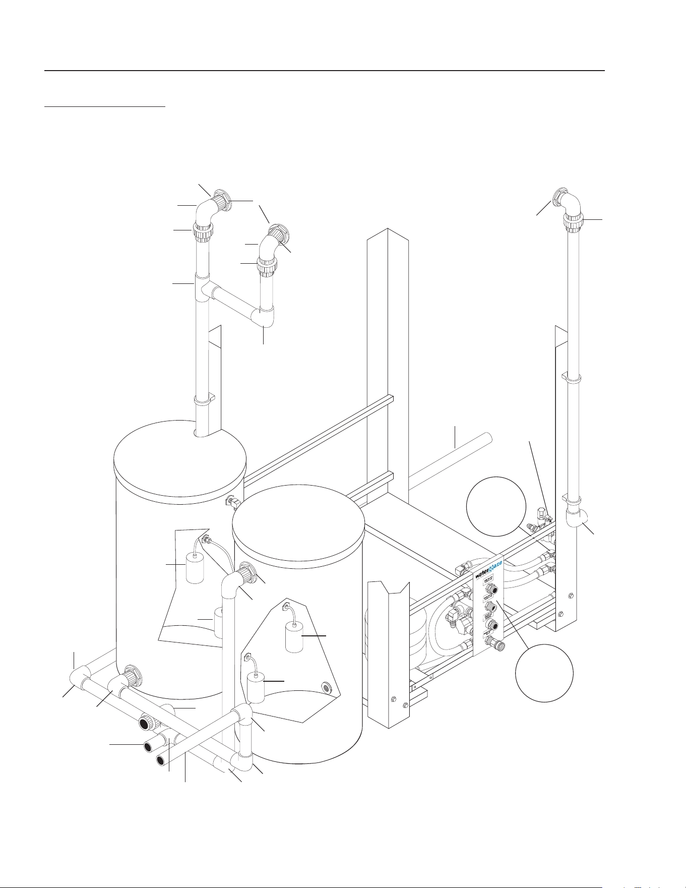
STORAGE TANK
CL-603
8
6
2
10
6
4
3
4
5
3
1
3
2
7
8
For
Detail See
Manifold
Breakdown
Illus.
For
Detail See
Water
Panel
Illus.
Return Line
To Pit
(Backwash)
Storage
Tank
#2
Storage
Tank
#1
9
8
9
10
8
8
8
8
8
Return Line
From
Filter Pac
Connections
To Optional
Filter Pac
Pallets
Return
Line To Pit
(Backwash)
8
Inlet To
Filter
Pac
Valve #10

CLARIFIER SERIES OPERATOR’S MANUAL
31
CL-600 • #8.913-968.0 -C
ITEM PART NO. DESCRIPTION QTY
1 8.706-479.0 Bulkhead 2" Poly 2
2 8.706-451.0 Adapter, 2" x MT, PVC 80 2
3 8.706-382.0 Elbow, 2" S x S, PVC 80, 90° 3
4 8.706-474.0 Union, 2" S x S, PVC 80 2
5 8.706-434.0 Tee, 2", S x Sx S, PVC80 1
6 8.706-490.0 Bulkhead, 1-1/2" S x S Polypro 2
7 8.706-469.0 Union, 1-1/2" S x S, PVC 80 1
8 8.706-374.0 Elbow, 1-1/2" S x S,
PVC 80, 90° 9
9 8.716-143.0 Switch, Float, N/C 2
10 8.716-142.0 Switch, Float, N/O 2
STORAGE TANK
PARTS LIST
CL-603
32
CLARIFIER SERIES OPERATOR’S MANUAL
CL-600 • #8.913-968.0 -C
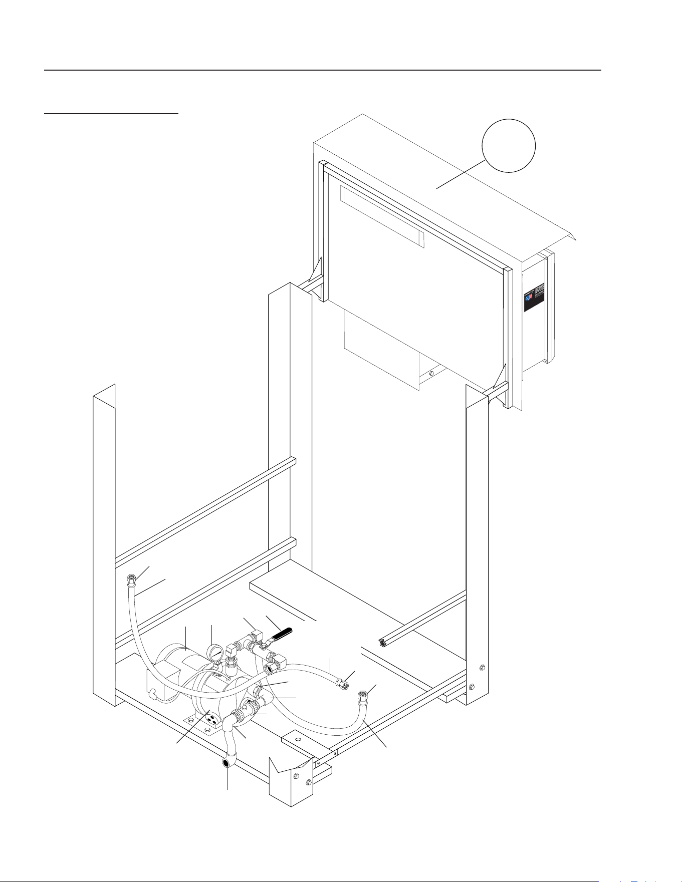
TRANSFER PUMP
CL-603
4
6
3
2
8
7
1
1
5
8
To Water
Panel Assy.
To Vertical
Storage Tank
#1
1
To Vertical
Storage Tank
#2
Transfer
Pump
For
Detail See
Control
Panel
Illus.
To
Water Panel
Assy.

CLARIFIER SERIES OPERATOR’S MANUAL
33
CL-600 • #8.913-968.0 -C
ITEM PART NO. DESCRIPTION QTY
1 9.802-151.0 Swivel, 1/2" JIC Fem, Push-On 3
2 9.802-131.0 Elbow, 1/2" JIC x 1/2" 90° 1
3 8.707-211.0 Valve, 1/2" 1
4 8.715-402.0 Pump, Transfer, 2 HP, 208/230V
1 PH CL603A 1
8.715-404.0 Pump, Transfer, 2 HP,
208/230/460V, 3 PH,
CL603B, CL603C 1
5 8.707-300.0 Valve, 1" PVC Ball Check 1
6 8.712-154.0 Gauge, Pressure 0-100, 1/4" 1
7 8.706-378.0 Elbow, 1", S x FT, PVC 80, 90° 1
8.706-439.0 ▲ Nipple, 1" PVC 80, Close 1
8 8.706-405.0 Bushing, 1-1/4" x 1" MT x FT,
PVC 80 1
▲ Not Shown
TRANSFER PUMP
CL-603 PARTS LIST
34
CLARIFIER SERIES OPERATOR’S MANUAL
CL-600 • #8.913-968.0 -C
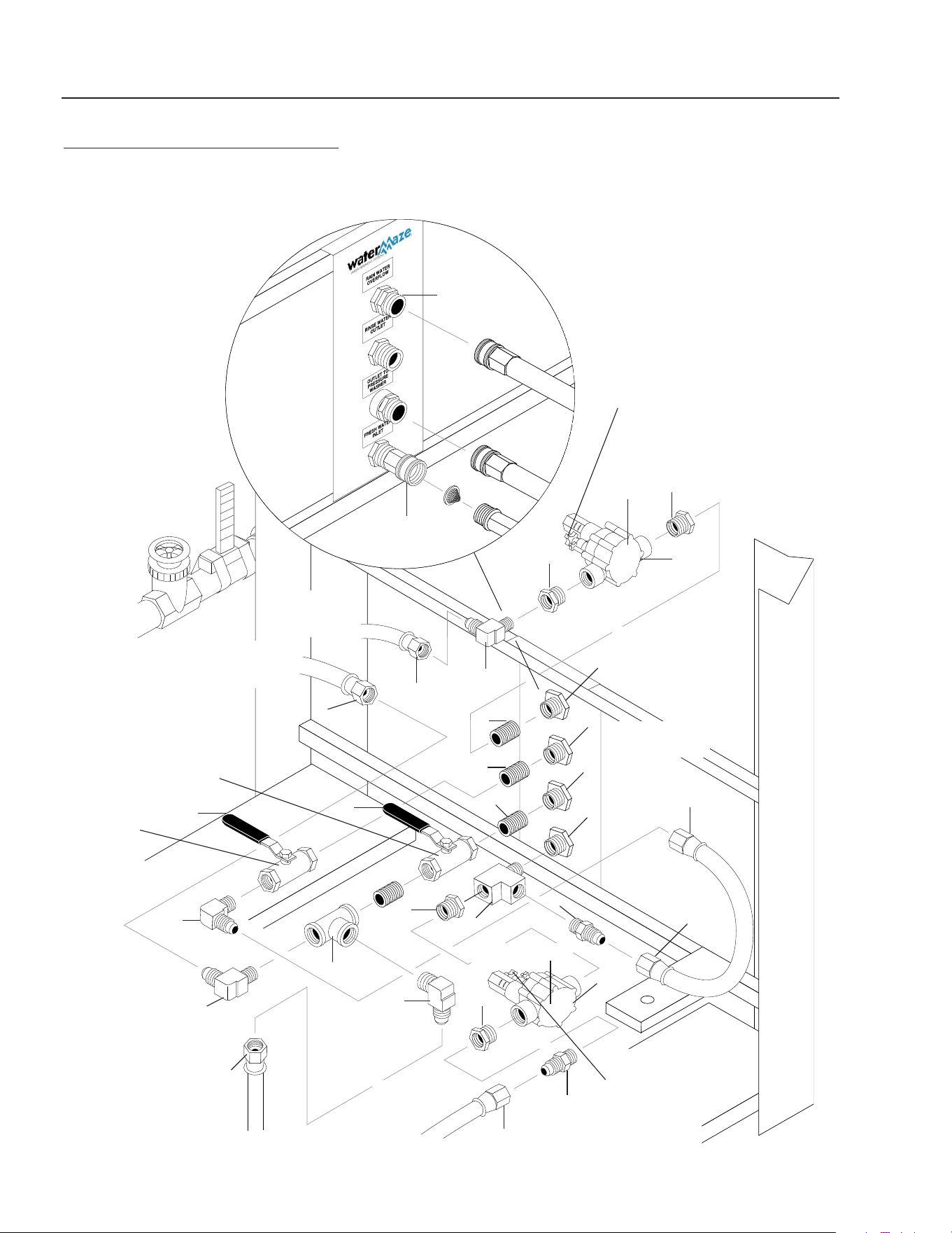
89139680-7
OZONE • OIL BUCKET • SLUDGE TUB ASSEMBLY
CL-600/603
2
10
3
11
12
Sludge
Collection
Tub
1
2
3
Oil
Skimmer
Collection
Barrel
9 - Valve
#3
6
7
4 - Valve
#1
5
8
Ozone
Mix
Pump
To
Manifold
Assy.
Main
Tank
Drain
Line
to Pit
Valve #2
Valve #5
Valve #4
ORP
Injector
16
14
13
15
17
6
18
19
20
22
21

CLARIFIER SERIES OPERATOR’S MANUAL
35
CL-600 • #8.913-968.0 -C
ITEM PART NO. DESCRIPTION QTY
1 8.706-469.0 Union, 1-1/2" S x S PVC 80 1
2 8.706-484.0 Bulkhead, 1" Polypro 2
8.706-439.0 ▲ Nipple, 1" PVC 80, Close 2
3 8.706-378.0 Elbow, 1" Slip x FIPT 2
4 8.707-344.0 Valve, Gate, 1-1/2" S x S 1
5 8.712-136.0 Gauge, Flowmeter
(Clamps Incuded) 1
6 8.706-360.0 PIPE, 1.5" PVC Clear 8"
7 8.709-431.0 Injector, Ozone 1
8 8.917-760.0 Pump, Ozone, 3/4 HP, 230V,
1 PH CL603A 1
8.723-219.0 Pump, Ozone, 3/4 HP, 230/460V
1 PH CL603B, CL603C 1
8.917-759.0 Pump, Ozone, 3/4 HP, 115V,
1 PH, CL 600D 1
9 8.707-359.0 Valve, 1", 80#, S x S 1
10 8.906-479.0 Tank, Oil Separation Assembly 1
11 8.719-179.0 Tub, Plastic 1
12 8.719-191.0 Bag, Sludge, Biodegradable 1
13 8.750-743.0 Bulkhead, 1/2" Polypro 1
14 8.706-467.0 Nipple, 1/2" Close, PVC 80 1
15 8.706-370.0 Elbow, 1/2" FIPT x FIPT, 90° 1
16 8.706-407.0 Bushing, 1/2" x 1/4" MT x FT,
PVC 80 1
17 8.750-270.0 Fitting, Compression, 1-1/2" 2
18 8.706-374.0 Elbow, 1-1/2" S x S
PVC 80, 90° 2
19 8.706-469.0 UNION,1-1/2" Slip x Slip
PVC 80 1
20 8.706-406.0 Bushing, 1 1/2" x 1/2"
SPGXFT, PVC 80 3
21 8.706-387.0 Plug, 1/2' MIPT, PVC 80 3
22 8.706-426.0 Tee, 1.5" S x S x S, PVC 80 3
▲ Not Shown
OZONE • OIL BUCKET • SLUDGE TUB ASSEMBLY
CL-600/603 PARTS LIST
36
CLARIFIER SERIES OPERATOR’S MANUAL
CL-600 • #8.913-968.0 -C
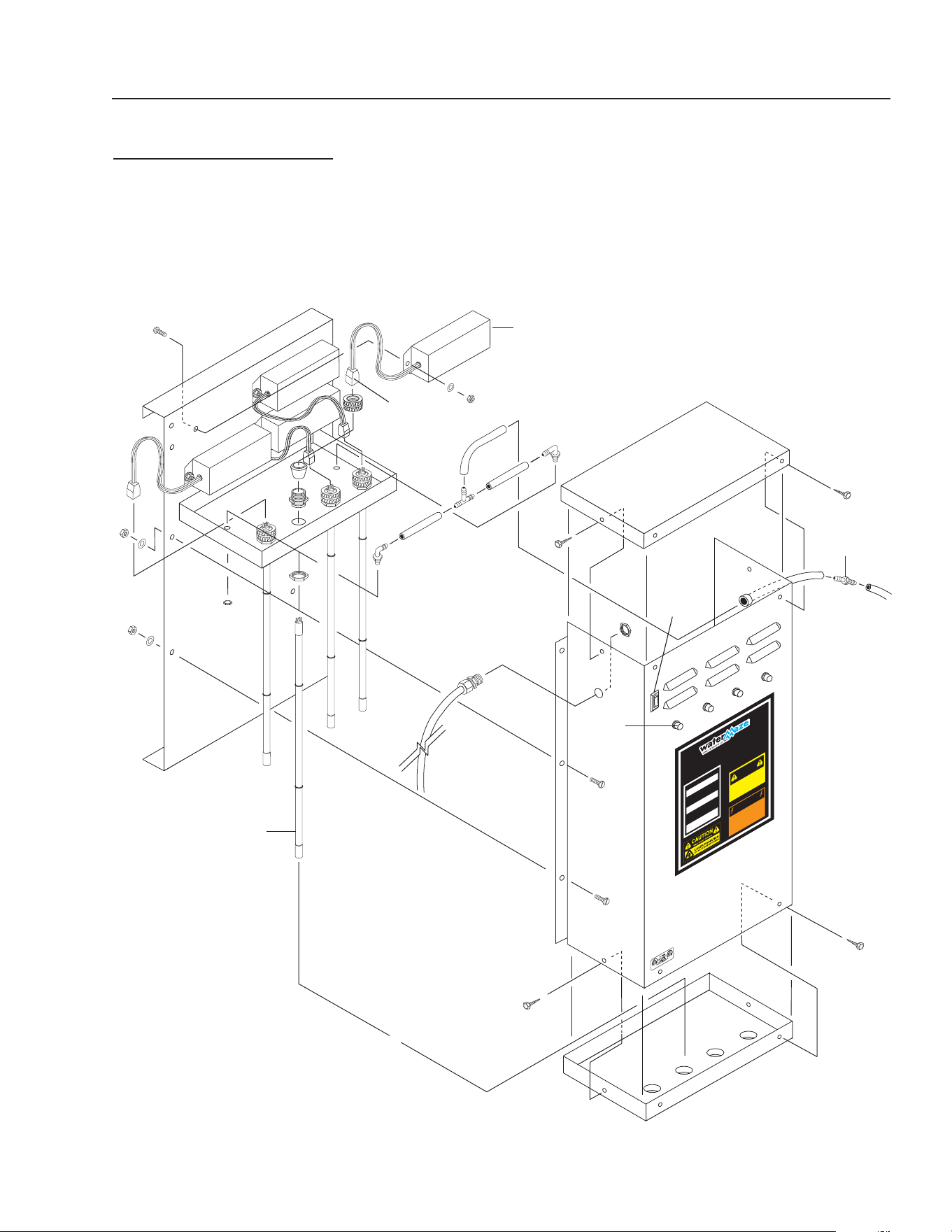
89139680-2
OPTIONAL FILTER PAC III
8.903-715.0, 120/230V, 1PH
8.903-716.0, 230/460V, 3 PH
11
4
3
1
2
6
11
7
5A
5B
12
15
14
13
6
8
11
16
17
16
17
18
14

CLARIFIER SERIES OPERATOR’S MANUAL
37
CL-600 • #8.913-968.0 -C
OPTIONAL FILTER PAC III
8.903-715.0
PARTS LIST
ITEM PART NO. DESCRIPTION QTY
1 8.707-344.0 Valve, Gate, 1-1/2" S x S,
PVC Sch 80 1
2 8.712-136.0 Gauge, Flowmeter, 1-1/2" 1
3 8.723-198.0 Pump, Filter, 2 HP, 230V 1 PH 1
8.756-758.0 Pump, Scot 208/230-460V 3PH,
20GPM/50PSI 1
4 8.706-469.0 Union, 1-1/2" S x S,
PVC 80# 12
5A/B 8.726-028.0 Filter Tank, Media w/Valve 2
5A 8.718-920.0 ▲ Sand, .45 - .55 mm 200 lbs
8.718-921.0 ▲ Gravel, 1/4" x 1/8" 100 lbs
8.718-922.0 ▲ Anthracite #1,
.60 - .80 mm 30 lbs
8.900-451.0 Label, Multi-Media Filter 1
5B 8.718-926.0 ▲ ‡ Carbon Activated 150 lbs
8.900-454.0 ▲ Label, Carbasorb Filter 1
6 8.723-206.0 Filter Tank 2
6A 8.723-205.0 ▲ Cartridge Filter 2
8.900-452.0 ▲ Label, Cartridge Filter 2
7 8.723-209.0 Valve, 6 Pos. w/Unions 2
8 8.706-374.0 Elbow, 90°, 1-1/2" S x S,
PVC Sch 80 26
9 8.706-413.0 ▲ Bushing, 2" x 1-1/2" Slip,
PVC 80 7
10 8.706-426.0 ▲ Tee, 1-1/2" S x S x S,
PVC Sch 80 4
11 8.706-360.0 Pipe, 1-1/2" PVC, Clear 3.2 ft
12 8.706-367.0 Pipe, 1-1/2", PVC 80 22 ft
13 8.706-421.0 Hanger, Pipe, 1-1/2" Click #47 5
14 3030-8410 Strap, 84", Filter 1
15 8.911-223.0 Tab, Filter Mounting 8
16 8.750-270.0 Fitting, Comp, 1-1/2" 6
17 8.709-340.0 Strap, Hold Down, Neck 2
18 8.917-819.0 Ring Assy, Filter Base, 19.6" 2
▲ Not Shown ‡ Dry Weight
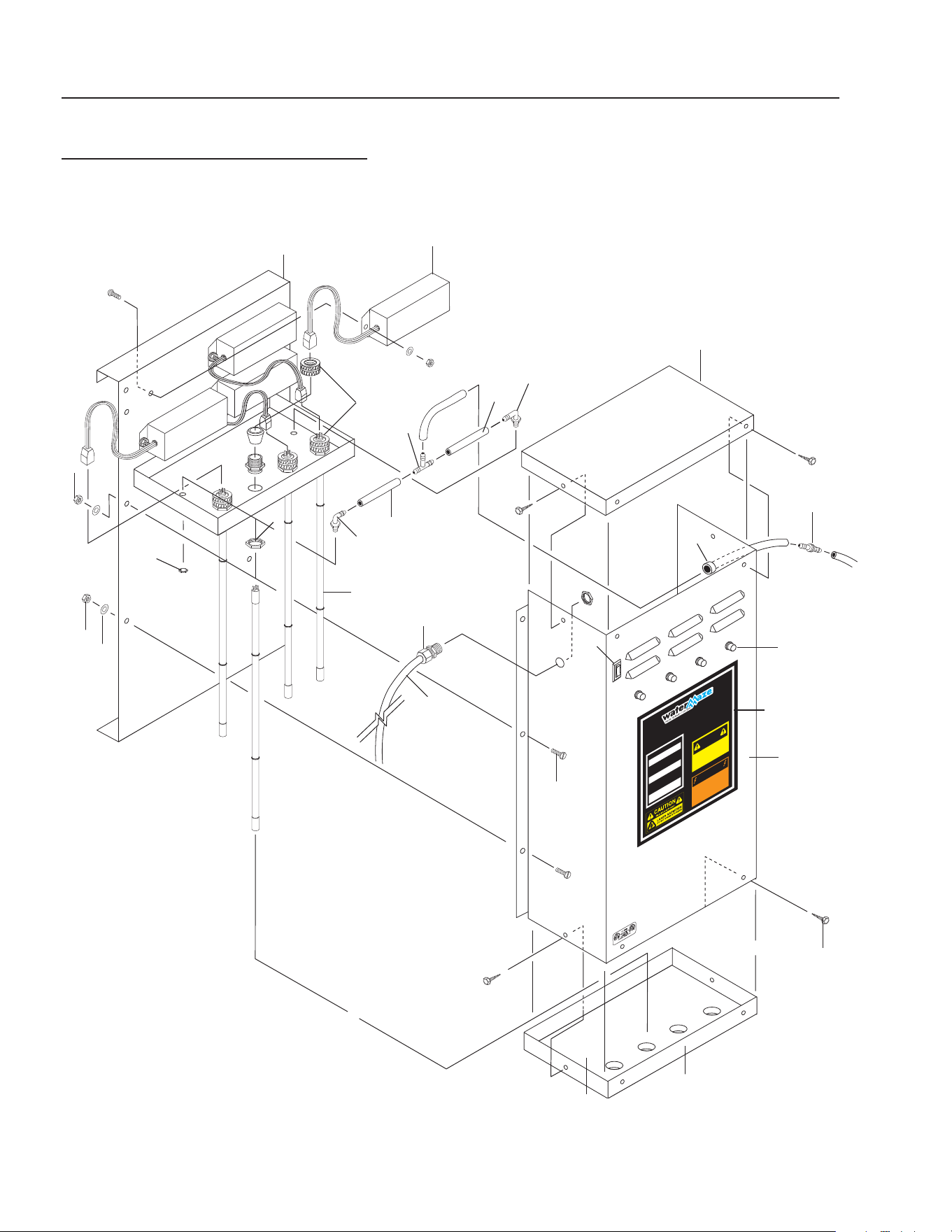
38
CLARIFIER SERIES OPERATOR’S MANUAL
CL-600 • #8.913-968.0 -C
OZONE GENERATOR
DISCONNECT F
R
OM ELECTRICAL
SUPP
L
Y BEFORE SE
R
VICING.
DESCONECTE LA CORRIENTE ELECTRICA
ANTES DE
D
AR SE
R
VICI
O
.
COUPER
L
’ALIMEN
TA
TION ÉLECTRI
Q
UE
AV
ANT DE F
AIRE UNE RÉ
PAR
A
TION.
DISCONNECT F
R
OM ELECTRICAL
SUPP
L
Y BEFORE SE
R
VICING.
DESCONECTE LA CORRIENTE ELECTRICA
ANTES DE D
AR SE
R
VICI
O
.
COUPER
L’A L I M E N
TA
TION ÉLECTRI
Q
UE
AV
ANT DE
FAIRE UNE RÉ
PAR
A
TION.
INDICATOR
L
IGHT OPERAT
I
O
N
A b
r
ight conti
n
uous light indicates UV
light or ballast de
f
ecti
v
e
.
Una luz luminosa indica que la luz ult
r
a-
violeta o t
r
ans
f
o
rmador está de
f
ectuos
o
.
Une lumière claire indique que la lumière
ult
r
a
violette ou le t
r
ansf
o
r
mateur est
déf
ectueux.
OPER
A
CION DE LA LUZ
INDICADORA
OPÉR
A
TION DE LE LAMPE
INDIC
A
TEUR
HOT!
C
ALIENTE!
CHA
UD!
CAUTION
PREC
A
UCION
A
TTENTION
8.900-455.0
!
WARNING!
A
T
ENCIO
N
!
/
A
TT
ENT
ION!
!
89139680-6
OZONE GENERATOR-CL-600
SERIES 400
14
12
11
14
9
23
24
20
13
15
6
17
22
8, 25
10
21
4
7
19
18
16
1
5
11
9
3
2

CLARIFIER SERIES OPERATOR’S MANUAL
39
CL-600 • #8.913-968.0 -C
OZONE GENERATOR-CL-600
SERIES 400
PARTS LIST
ITEM PART NO. DESCRIPTION QTY
1 8.913-357.0 Ozone Box, Back, 400 1
2 8.913-360.0 Ozone Box, Front, 400 1
3 9.802-455.0 Light, Indicator, Green 4
4 9.802-523.0 Locknut, 3/4" Conduit 4
5 8.716-583.0 Connector, Aluminum Cord
SCH1037 4
6 8.707-355.0 Ozone Check Valve 1
7 8.716-600.0 Lamp, Ozone Replacement 4
8 8.900-455.0 Label, Ozone Generator 1
9 9.802-696.0 Nut, 10/32", NF ST ST KEP 12
10 8.706-570.0 Locknut, 3/8", Nylon 2
11 8.706-585.0 Connector, 3/8" x 3/8",
Male Elbow (Poly) 2
12 8.706-594.0 Tee, 3/8" Poly 1
13 8.706-733.0 Bushing, 1/2" Snap 1
14 8.711-733.0 Tubing, 3/8" x 1/2", Clear Vinyl 6
15 9.802-423.0 Cord, Service, SEO, 16/3 8ft.
16 9.802-453.0 Switch, Curvette, 120V & 220V 1
17 9.802-514.0 Strain Relief, 1/2" NPT
Ozone Gen 1
18 8.706-545.0 Cushion, 1/2", 13-3/4" x 5-3/4",
Rubber 1
19 8.913-358.0 Ozone Box, Top, 400 1
20 8.913-359.0 Ozone Box, Bottom, 400 1
21 8.716-590.0 Ballast, 120/240 Volt
Ozone Generator* 4
8.716-591.0 Ballast, 220V 50 Hz 4
22 9.804-566.0 Screw, 10/32" x 1/2" Slot Pan
MS ZN 12
23 8.718-968.0 Washer, 10 x SAE ZN 12
24 9.802-798.0 Screw, #10 x 1/2" Tek Hex Head 8
25 9.800-022.0 Label, Voltage, 120V 1
* Voltage switch must match voltage of machine.
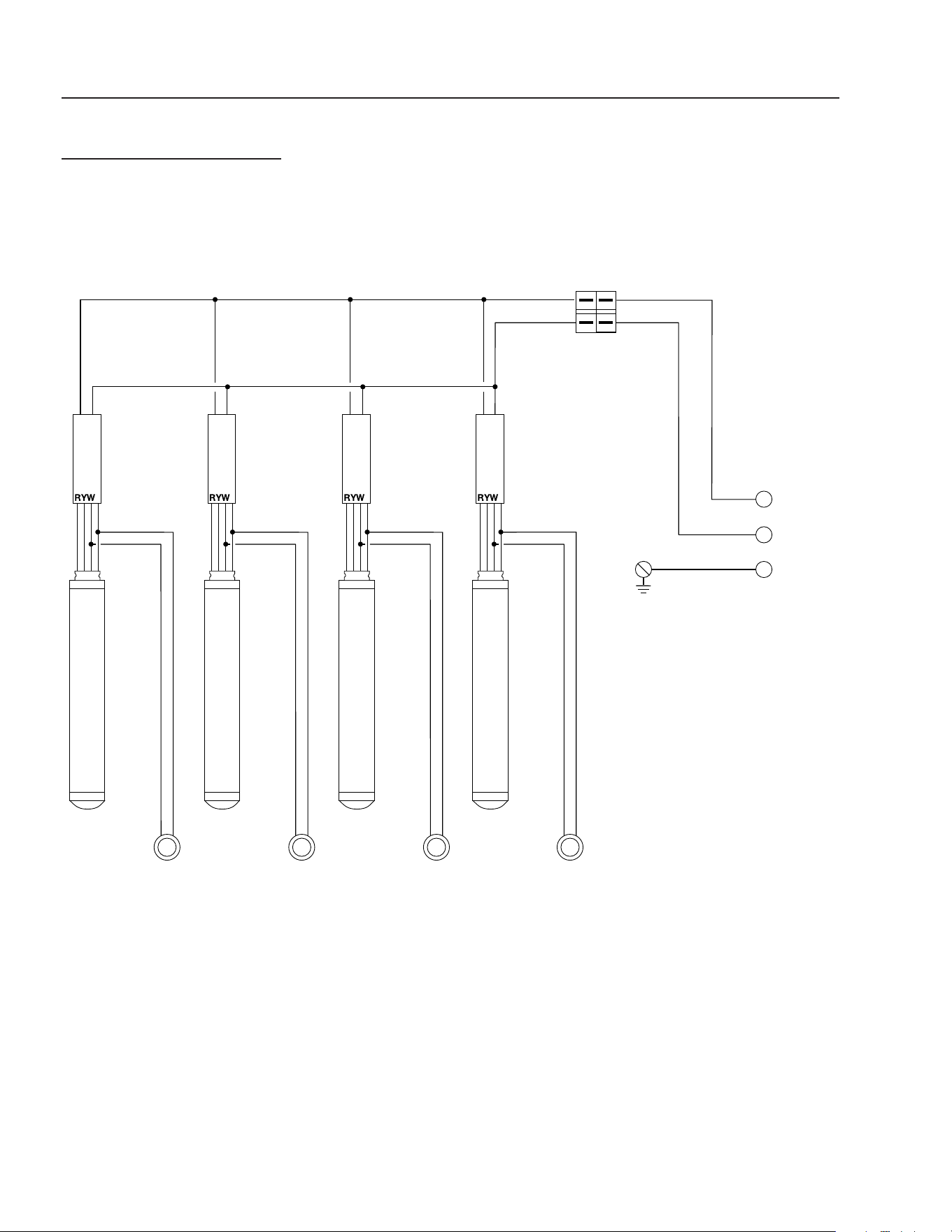
40
CLARIFIER SERIES OPERATOR’S MANUAL
CL-600 • #8.913-968.0 -C
OZONE GENERATOR
FOUR TUBE
POWER
IN
OZONE LIGHT
OZONE LIGHT
OZONE LIGHT
OZONE LIGHT
TRANSFORMER
TRANSFORMER
TRANSFORMER
TRANSFORMER
CONTROL
SWITCH
GROUND
BLBLBLBL
B
B
BB
BB
WWWW
W
INDICATING LIGHTS
NOTE:
RED INDICATING LIGHT OPERATION:
Bright continuous light indicates
UV light or ballast defective.
Dim continuous light
indicates proper operation.
NOTE:
B - BLACK
W - WHITE
R - RED
G -GREEN
Y - YELLOW
BL - BLUE
B
G
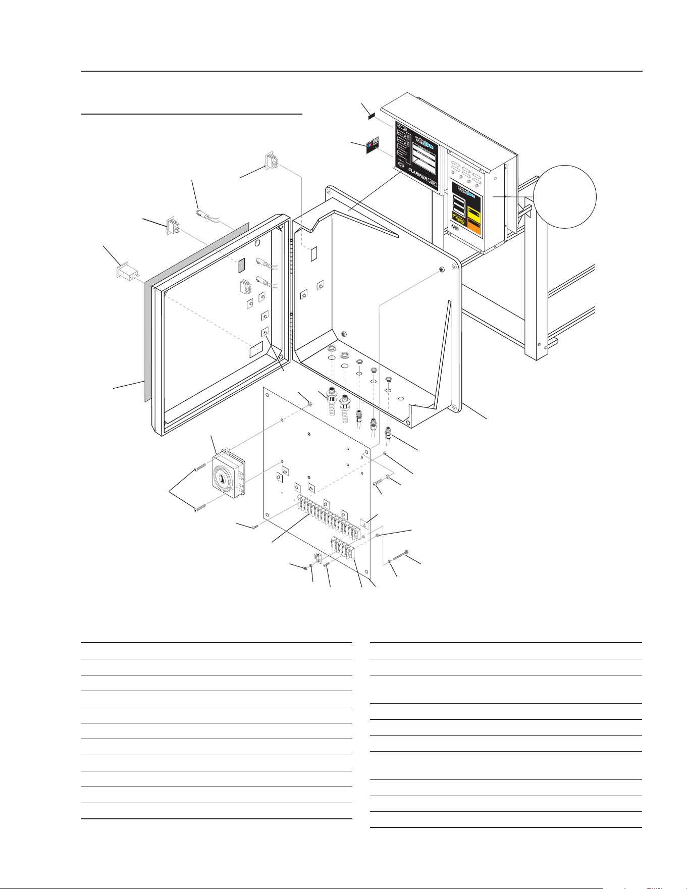
CLARIFIER SERIES OPERATOR’S MANUAL
41
CL-600 • #8.913-968.0 -C
89139680-3
GROUND
FLOAT SWITCH
O
V
ERIDE
O
Z
ONE GENER
ATO R
DISCONNECT F
R
OM E
LECTRICAL
S
UPP
L
Y
BEF
ORE SE
R
VICING.
DESCON
E
CTE LA CORRIENTE ELECTRICA
A
N
TE
S
DE
D
AR SE
R
VI
C
IO
.
C
OUP
ER
L’AL
I
ME
N
TA
TION ÉLEC
T
RI
Q
U
E
A
VANT DE
F
A
I
R
E
UN
E
RÉ
P
A
R
A
TION.
DIS
C
ONNECT
F
R
OM ELECTRICAL
SUPP
L
Y BEF
ORE
SE
R
VICIN
G
.
DE
S
CO
N
ECTE LA
C
ORRIE
N
TE ELEC
T
RICA
A
N
T
E
S
D
E
D
AR
S
ER
V
I
C
I
O
.
C
O
UP
E
R
L
’ALIMEN
TA
TION ÉLECTRI
Q
U
E
A
V
A
N
T DE
F
AIR
E
UN
E
R
É
P
A
R
A
T
I
ON
.
I
NDICATOR
L
IGHT
OPE
RAT
I
O
N
A
b
r
ight conti
n
uou
s
light indic
a
te
s U
V
l
i
gh
t
or ballast de
f
ecti
v
e
.
Una luz luminosa indica que la luz ult
r
a-
viole
t
a
o
t
r
ans
f
o
r
mador está de
f
ec
tuo
s
o
.
U
n
e
l
u
mière claire indique qu
e
la
l
u
m
i
ère
ultr
a
vi
o
le
t
te
o
u le t
r
ans
f
o
r
m
at
e
ur
e
st
dé
f
ectueu
x
.
OPERA
CION
DE
L
A
LUZ
INDI
CADORA
OPÉR
A
TI
ON
DE LE
LAMP
E
INDI
C
A
TE
U
R
HO
T!
C
ALIENTE!
C
H
AUD!
C
A
UTION
PRE
C
A
U
C
I
O
N
A
TTENTION
8.900-455.0
!
W
ARNING!
A
T
ENC
IO
N
!
/
A
TT
ENT
I
ON
!
!
CLARIFIER CONTROL PANEL
EXPLODED VIEW & PARTS LIST
STANDARD 600D
For Detail
See Ozone
Generator
Breakdown
Illus.
1
14
12
13
16
15
2
21
19
19
20
4
7
5
6
18
17
ITEM PART NO. DESCRIPTION QTY
1 8.716-281.0 Box, Electrical 1
2 9.802-514.0 Strain Relief 3
3 8.913-206.0 Standoff, Elec Box 1
4 9.802-762.0 Screw, 10/32' x 1-1/4" 1
5 9.802-695.0 Nut, 10/32", Keps 8
6 8.716-460.0 Terminal, Grounding Lug 1
7 9.800-040.0 Label, Ground 1
8 9.802-759.0 Screw, 10/32" x 1/2" 6
9 9.802-491.0 Block, Terminal, 4 Pole 1
10 9.802-493.0 Block, Terminal, 16 Pole 1
11 8.716-253.0 Timer, 24 Hr Pin, 120V 20A 1
ITEM PART NO. DESCRIPTION QTY
12 8.716-051.0 Switch, Curvette, 120/230 3
13 9.802-455.0 Light, Indicator, Green, 3
14 9.802-283.0 Hour Meter, 24-240VAC
50/60HZ 1
15 8.940-055.0 Label, Assembled in USA 1
16 8.900-465.0 Label, Float, Overide 1
17 8.900-524.0 Label, Control Panel 1
18 9.802-749.0 Screw, 8/32" x 3/4"
BHSOC, CS 4
19 9.802-785.0 Nut, 8/32" Keps 4
20 8.716-533.0 Clamp, Tie Wrap, Adhesive 6
21 8.716-547.0 Strain Relief 2
▲ Not Shown
8
11
5
8
9
5
3
5
18
10
12
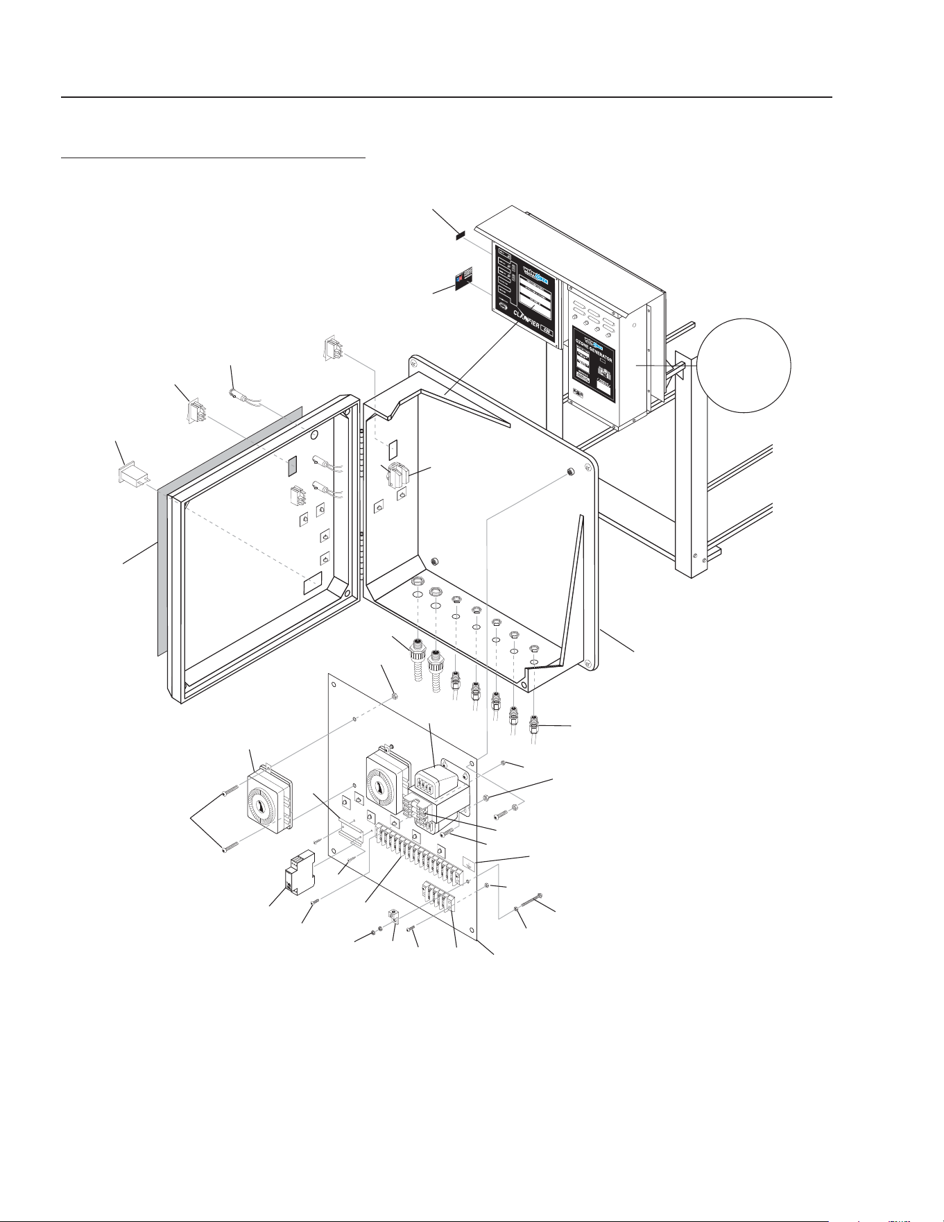
42
CLARIFIER SERIES OPERATOR’S MANUAL
CL-600 • #8.913-968.0 -C
89139680-4
GROUND
F
LOAT SWITCH
O
VERIDE
CLARIFIER CONTROL PANEL
EXPLODED VIEW
600D AUTO PURGE OPTION
14
For Detail
See Ozone
Generator
Breakdown
Illus.
1
7
8
15
16
10
19
18
11
17
2
4
8
5
5
3
5
24
24
23
20, 21
9
22
28
5
6
12
13
26
27
25
25

CLARIFIER SERIES OPERATOR’S MANUAL
43
CL-600 • #8.913-968.0 -C
CLARIFIER CONTROL PANEL
PARTS LIST
600D AUTO PURGE OPTION
ITEM PART NO. DESCRIPTION QTY
1 8.716-281.0 Box, Electrical 1
2 9.802-514.0 Strain Relief 5
3 8.913-206.0 Standoff, Elec Box 1
4 9.802-762.0 Screw, 10/32' x 1-1/4" 1
5 9.802-695.0 Nut, 10/32", Keps 12
6 8.716-460.0 Terminal, Grounding Lug 1
7 9.800-040.0 Label, Ground 1
8 9.802-759.0 Screw, 10/32" x 1/2" 12
9 9.802-491.0 Block, Terminal, 4 Pole 1
10 9.802-493.0 Block, Terminal, 16 Pole 1
11 8.716-253.0 Timer, 24hr Pin, 120V/20A 2
12 8.716-051.0 Switch, Curvette, 120/230 3
13 9.802-455.0 Light, Indicator, Green, 3
14 9.802-283.0 Hour Meter, 24-240VAC
50/60HZ 1
15 8.940-055.0 Label, Assembled in USA 1
16 8.900-465.0 Label, Float, Overide 1
17 8.900-524.0 Label, Control Panel 1
18 9.802-457.0 Din Rail, 35mm 3"
19 8.718-936.0 Screw, #8 x 1/2" Tek 2
20 9.803-663.0 Fuse, KTK-R2 600V Midget
Auto Purge Option and
ORP/PH Controller Option 2
21 9.803-977.0 Fuse, 2-1/2 Amp, 250V
Auto Purge Option and
ORP/PH Controller Option 1
22 9.802-553.0 Transformer, 120/240V-24V
Auto Purge Option and
ORP/PH Controller Option 1
23 8.751-306.0 Timer, Multi-Function
240-120/240V 1
24 9.802-749.0 Screw, 8/32" X 3/4"
BHSOC, CS 4
25 9.802-785.0 Nut, 8/32" Keps 4
26 8.751-916.0 Switch, Green PB 1
27 8.751-913.0 Block, Contact, N/O, M22-K10 1
28 8.716-547.0 Strain Relief 2
▲ Not Shown

44
CLARIFIER SERIES OPERATOR’S MANUAL
CL-600 • #8.913-968.0 -C
TROUBLESHOOTING - CLARIFIER
PROBLEM POSSIBLE CAUSE SOLUTION
NO FLOW OF WATER
INTO THE CLARIFIER
Control switch not in “ON” position Turn switch to “ON” position.
Power not turned “ON” at breaker box Turn “ON” power at breaker box.
Float in sump in down position Add water to sump.
Debris in sump impeller Unplug pump and remove from container.
Flow valve not closed Open valve
Dirt lodged in control valve Clean as needed.
Frozen water in lines or valves Thaw out with warm water.
WATER FLOWING OVER
THE CLARIFIER
Tank not level Level tank.
Water coming into the Clarifi er faster
than 5 - 30 gpm
Adjust fl ow control valve.
Discharge line plugged Remove obstruction.
Pump not wired in Wire in pump.

CLARIFIER SERIES OPERATOR’S MANUAL
45
CL-600 • #8.913-968.0 -C
TROUBLESHOOTING - PUMP
PROBLEM POSSIBLE CAUSE SOLUTION
PUMP DOES NOT
TURN ON
Circuit breaker shut “OFF” Turn “ON” circuit breaker.
Accumulation of debris on fl oat Clean fl oat.
Float obstruction Check fl oat path and provide clearance.
Defective switch Have pump serviced by authorized service center.
Defective motor Have pump serviced by authorized service center.
Low line voltage If voltage under recommended minimum, check
size of wiring from main switch on property. If OK,
contact power comopany.
PUMP WILL NOT
SHUT OFF
Float obstruction Check fl oat and fl oat path and provide clearance.
Pump is air locked (Transfer Pump) Shut power off for approximately 1 minute, then re-
start. Repeat several times to clear air from pump.
Liquid infl ow matches pump capacity Larger pump required.
Defective fl oat switch Disconnect switch, check with ohmmeter.
PUMP RUNS BUT
DOES NOT DIS-
CHARGE LIQUID
Check valve installed backwards
(Transfer Pump)
Check fl ow indicating arrow on check valve body to
insure it is installed properly.
Check valve stuck or plugged (Trans-
fer Pump
Remove check valve and inspect for proper opera-
tion.
Lift too high for pump Check rating table.
Inlet to impeller plugged Pull pump and clean.
Low line voltage If voltage under recommended minimum, check
size of wiring from main switch on property. If OK,
contact power company.
Clogged impeller Remove housing, unclog.
Faulty motor protector Replace pump.
Very low head or lift Increase head or lift.
Sump pit too small Increase size of pit
PUMP DOES NOT
DELIVER RATED
CAPACITY
Low voltage, speed to slow Check for proper supply voltage to make certain it
corresponds to nameplate voltage.
Impeller or discharge pipe is clogged Pull pump and clean. Check pipe for scale or cor-
rosion.
Impeller wear due to abrasives Replace worn impeller.
PUMP CYCLES
CONTINUALLY
Check valve leaking (Transfer Pump) Inspect check valve for correct operation.
Low line voltage If voltage under recommended minimum, check
size of wiring from main switch on property. If OK,
contact power company.
Worn or defective pump parts or
plugged impeller
Replace worn parts or entire pump. Clean parts if
required.
Pump air locked Turn pump “ON” and “OFF” severeal times. Fill
hose manually with water.

46
CLARIFIER SERIES OPERATOR’S MANUAL
CL-600 • #8.913-968.0 -C
TROUBLESHOOTING - PUMP MOTOR
PROBLEM POSSIBLE CAUSE SOLUTION
MOTOR WILL
NOT RUN
Disconnect switch is “OFF” Be sure switch is “ON”.
Breaker is tripped Reset breaker.
Starting switch is defective Replace starting switch.
Wires at motor are loose, disconnected
or wired incorrectly
Refer to instructions on wiring. Check and
tighten all wiring.
Pressure switch contacts are dirty
(Transfer Pump)
Clean by sliding piece of plain paper (or crocus
cloth) between contacts.
MOTOR RUNS
HOT AND
OVERLOAD
KICKS OFF
Motor is wired incorrectly Refer to instructions on wiring.
Voltage is too low Check with power company. Install heavier wir-
ing if wire size is too small. See wiring instruc-
tions.
Pump cycles too frequently See section on previous page pump cycles
continually.
Defective fl oat switch Disconnect switch, check with ohmmeter.
MOTOR RUNS
BUT NO WATER
IS DELIVERED
Pump in a new installation did not pick
up prime through:
a. Improper priming a. Re-prime (3 or 4 times may be needed) by
stopping and starting motor several times.
b. Air leaks b. Check all connections on suction line.
c. Leaking check valve (Transfer
Pump)
c. Clean and/or replace check valve.
Pump has lost its prime through:
a. Air leaks a. Check all connections on suction
line.
b. Water level below suction of pump b. Lower suction line into water and
re-prime.
Jet or impeller is plugged Clean jet or impeller, see maintenance.
Check valve is stuck in closed position Replace check valve.
Pipes are frozen Thaw pipes. Bury pipes below frost line. Heat
pipes below frost line. Heat pit or pump house.

CLARIFIER SERIES OPERATOR’S MANUAL
47
CL-600 • #8.913-968.0 -C
TROUBLESHOOTING - FILTER
PROBLEM POSSIBLE CAUSE SOLUTION
RUNNING AT
HIGH
PRESSURES
Multi-Media or Carbon Filter coated
with normal accumulation of dirt, etc
Backwash is needed.
Cartridge Filter plugged Cleaning is needed.
Obstruction in line to Tank #1 Remove obstruction.
DROP OFF OF
DISCHARGE FLOW
Multi-Media or Carbasorb Filter coated
with normal accumulation of dirt, etc
Backwash is needed
Valve #1 closed Open valve.
Cartridge Filter clogged Clean.
Pump impeller vanes clogged Cleaning with a stiff wire through the pump
inlet opening will usually work. Alternate would
be to disassemble and clean.
Air leak on suction side of pump Check cover gasket, hand knobs, clamps, etc.
Replace or tighten as necessary.
Electric motor running less than rated
RPM (under speed)
Consult pump motor troubleshooting guide.
NOTE: Most motor problems are due to:
1. Undersized or improper wiring.
2. Power cutbacks.
3. A combination of both.

48
CLARIFIER SERIES OPERATOR’S MANUAL
CL-600 • #8.913-968.0 -C
TROUBLESHOOTING - WATER SOLENOID
PROBLEM POSSIBLE CAUSE SOLUTION
VALVE LEAKS
WHEN “OFF”
Dirt or debris on diaphragm seat Clean diaphragm seat.
Solenoid not fully closed after manual
operation
Turn solenoid clockwise to fully seated position.
Solenoid O-ring damaged or twisted Turn off water, inspect O-ring and reseat if twisted;
replace if damaged.
Diaphragm damaged Turn off water, remove bonnet screws and inspect
diaphragm for nicks or damage.
NOTE: Diaphragm has one bleed hole molded
into it. Replace if necessary, with diaphragm kit.
Dirt interfering with solenoid operation Turn off water, remove solenoid and fl ush seating
surface in bonnet and at bottom of solenoid with
water.
Solenoid damaged Turn off water supply and replace solenoid.
WATER WON'T
SHUT OFF
Valve in manual “ON” Turn solenoid clockwise to “OFF” position.
Diaphragm bleed hole blocked Use Manual Flush Mode. Turn water supply “OFF”
and immediately back “ON” to clear blockage. If
still blocked, turn off water and inspect diaphragm
looking for blockage.
Damaged solenoid Turn off water supply and replace solenoid.
LOW OR INADEQUATE
FLOW CONDITION
Water running elsewhere using up
pressure
Turn off water that is running elsewhere.
Too many solenoids running at once Adjust so water is running to only one solenoid.
Gate valve not fully open Open gate valve fully.
Pipeline blockage Clear pipeline.
VALVE WON'T TURN
ON ELECTRICALLY
No power to solenoid Make sure solenoid has power.
Low voltage Make sure there are 24 volts.
No water pressure Make sure water pressure is available to valve.
Turn off water and, without cutting wires, unscrew
and swap solenoids between valves. Turn on
water and test again. If problem stems from the
solenoid, replace solenoid.

CLARIFIER SERIES OPERATOR’S MANUAL
49
CL-600 • #8.913-968.0 -C
TROUBLESHOOTING - WATER SEALS
PROBLEM POSSIBLE CAUSE SOLUTION
CRACKED OR BROKEN
STATIONARY SEAT
(CERAMIC)
Seal ran dry and heated up. When liquid
reached seal faces it was cooler, caus-
ing thermal cracks
Check to insure seal chamber is full of liq-
uid before starting pump. On high tempera-
ture application, insure proper fl ushing at
seal faces.
CARBON WASHER
SCORED AND GROOVED
Dirty system Have system cleaned and fl ushed. Con-
sider use of Tungsten Carbide or Silicon
Carbide Rings.
CARBON WASHER WORN
UNEVENLY
Seal improperly installed Check installation instructions for proper
assembly.
FLEXIBLE DIAPHRAGM
BROKEN
Coupling misalignment Realign pump and motor.
SHORT SEAL LIFE IN
TREATED SYSTEMS
Treatment level and temperature higher
than anticipated
Use Viton Elastomers, High Temperature
Carbon, Ni Resist Tungsten Carbide or
Silicon Carbide Seat
BUNA DIAPHRAGM
HARD BRITTLE. RAPID
CARBON WEAR
Air leak on suction side of pump Check cover gasket, hand knobs, hose,
clamps, etc. Tighten or replace as neces-
sary.
DIAPHRAGM SOFT AND
STICKY; APPEARS TO BE
DISSOLVING
Bellows not compatible with material be-
ing pumped
Consult factory for recommendation advis-
ing of pumpage and temperature.

50
CLARIFIER SERIES OPERATOR’S MANUAL
CL-600 • #8.913-968.0 -C
SPECIFICATIONS
MODEL CL-600D CL-603A, B, C
MAXIMUM FLOW
30 gpm (113 LPM) 30 gpm (113 LPM)
OIL/WATER SEPARATOR CAPACITY
600 gal.
(2271 LITERS) 600 gal. (2271 LITERS)
SOLIDS SEPARATION CHAMBER
Ye s Ye s
ELECTRICAL
120 Volt 1 PH 20 Amps
230 Volt 1 PH 22 Amps
230 Volt 3 PH 10 Amps
460 Volt 3 PH 8 Amps
SUMP PUMP SUBMERSIBLE
1/2 HP 1/2 HP
TRANSFER PUMP CENTRIFUGAL
N/A 2 HP
OIL SKIMMER
Ye s Ye s
OZONE GENERATOR
Series 400 Series 400
COALESCING PACK
340 sq. ft.
(31.6M
2
) 340 sq. ft. (31.6M
2
)
CLARIFIED HOLDING TANK
N/A
65 gal.
(246 LITERS)
FILTERED WATER HOLDING TANK
N/A
65 gal.
(246 LITERS)
ORP/pH CONTROLLER
Optional Optional
ELECTRICAL PANEL
Nema 4 Nema 4
DIMENSIONS (L x W x H)
60" x 83" x 106"
(152CM/211CM/269C
60" x 83" x 106"(152CM/211CM/269CM)
NET DRY WEIGHT (approx.)
835 lbs.
(379 KG) 975 lbs. (442 KG)
MODEL FILTER PAC III
30-778, 30-778B
MAXIMUM FLOW
30 gpm (113 lpm)
ELECTRICAL
120/230 Volt 1 PH
230/460 Volt 3 PH
AMPS
21.0/10.5
5.6/2.8
FILTER PUMP
2 HP
MEDIA FILTER
330 lbs.
CARTRIDGE FILTER
(2) 200 sq. ft. (9.3m
2
)
10 micron
CARBON FILTER (degassed)
300 lbs. (135 kg)
DIMENSIONS (L x W x H)
61" x 62" x 46"
(155cm/155cm/117cm)
NET DRY WEIGHT (approx)
990 lbs.(449 kg)

CLARIFIER SERIES OPERATOR’S MANUAL
51
CL-600 • #8.913-968.0 -C
CONSUMABLE PARTS LIST
PART NUMBER DESCRIPTION
Water Maze Consumable Parts
8.716-600.0 Ozone Generator Replacement Lamp (110V & 220V)
8.718-920.0 .45 x .55 mm Sand (Std. bag size -50 lbs.)
8.718-921.0 1/4" x 1/8" Gravel (Std. bag size - 50 lbs.)
8.718-922.0 .60 x .80 mm #1 Anthracite (Std. bag size - 50 lbs.)
8.718-926.0 Activated Carbon (bulk)
8.718-933.0 Activated Carbon (50 lb. bag)
8.720-008.0 5-Way Test Strips
8.720-010.0 pH Test Strips
8.716-840.0 Cartridge Element, 200 sq. ft. 10 Micron
62-226V88475 O-Ring, Viton, 1-1/2"
2-332V88475 O-Ring, Viton, 2"

CLARIFIER SERIES OPERATOR’S MANUAL
CL-600 • #8.913-968.0 -C
LIMITED NEW PRODUCT WARRANTY
WASH WATER / WATER TREATMENT SYSTEMS
WHAT THIS WARRANTY COVERS
All
WATER MAZE
water treatment systems are warranted by to the original purchaser to be free from defects in materials
and workmanship under normal use, for the periods specified below. This Limited Warranty, subject to the exclusions shown
below, is calculated from the date of the original purchase, and applies to the original components only. Any parts replaced
under this warranty will assume the remainder of the part’s warranty period. A 60 day grace period will be given for installa-
tion.
ONE YEAR PARTS AND 30 DAY LABOR WARRANTY:
All components excluding normal wear items as described below.
WARRANTY PROVIDED BY OTHER MANUFACTURERS:
Motors, which are warranted by their respective manufacturers, are serviced through these manufacturers’ local authorized
service centers.
WATER MAZE
cannot provide warranty on these items.
WHAT THIS WARRANTY DOES NOT COVER
This warranty does not cover the following items:
1. Normal wear items, such as seals, filters, gaskets, O-rings, packings, pistons, brushes, filtering media, ozone
bulbs, sensors, UV scanners, oil-skimmer belt, impedance sensor. Minor leaks covered first time on original start-
up only.
2. Damage or malfunctions resulting from accidents, abuse, modifications, alterations, incorrect installation, improper
servicing, failure to follow
manufacturer’s maintenance instructions, or use of the equipment beyond its stated
usage specifications as contained in the operator’s manual.
3. Damage due to freezing, sludge build-up, chemical deterioration (oxidation, chloride or fluoride corrosion), and
rust.
4. Damage to components from fluctuations in electrical or water supply.
5. Normal maintenance service, including adjustments.
6. Transportation to service center, field labor charges, or freight damage.
7. Consumables and water quality.
WHAT YOU MUST DO TO OBTAIN WARRANTY SERVICE
While not required for warranty service, we request that you register your
WATER MAZE
Product by returning the com-
pleted registration card. In order to obtain warranty service on items warranted by
WATER MAZE
, you must return the
product to your Authorized
WATER MAZE
Dealer, freight prepaid, with proof of purchase, within the applicable warranty
period. If the product is permanently installed, you must notify your Authorized
WATER MAZE
Dealer of the defect. Your
Authorized
WATER MAZE
Dealer will file a claim with
WATER MAZE
, who must subsequently verify the defect. In most
cases, the part must be returned to
WATER MAZE
freight prepaid with the claim. For warranty service on components
warranted by other manufacturer’s, your Authorized
WATER MAZE
Dealer can help you obtain warranty service through
these manufacturers’ local authorized service centers.
LIMITATION OF LIABILITY
WATER MAZE’S
liability for special, incidental, or consequential damages is expressly disclaimed. In no event shall
WATER MAZE’S
liability exceed the purchase price of the product in question.
WATER MAZE
makes every effort to ensure
that all illustrations and specifications are correct, however, these do not imply a warranty that the product is merchantable
or fit for a particular purpose, or that the product will actually conform to the illustrations and specifications. Our obligation
under this warranty is expressly limited at our option to the replacement or repair at a service facility or factory designated
by us, of such part or parts as inspection shall disclose to have been defective. THE WARRANTY CONTAINED HEREIN
IS IN LIEU OF ALL OTHER WARRANTIES, EXPRESS OR IMPLIED, INCLUDING ANY IMPLIED WARRANTY WATER
QUALITY, MERCHANTABLIITY OR FITNESS FOR A PARTICULAR PURPOSE ARE EXPRESSLY LIMITED TO THE
DURATION OF THIS WARRANTY.
This warranty gives you specific legal rights and you may also have other rights which
vary from state to state.
WATER MAZE
does not authorize any other party, including authorized
WATER MAZE
Distributors,
to make any representation or promise on behalf of
WATER MAZE
, or to modify the terms, conditions, or limitations in any
way. It is the buyer’s responsibility to ensure that the installation and use of
WATER MAZE
products conforms to local
codes. While
WATER MAZE
attempts to assure that its products meet national codes, it cannot be responsible for how the
customer chooses to use or install the product. Some states do not allow limitations or exclusion or limitation of incidental or
consequential damages, so the above limitation or exclusion may not apply to you.


Form #8.913-968.0 • Printed in U.S.A.