


3
Safety Instructions
Information about the product such as its function, specifications and
appearance, price, components, and performance, can be changed without
notice. Samsung Electronics can change this document or product without
prior guidance.
Safety Instructions for Repair
Samsung is not liable for any damage to the product, any injury or any
other product safety issue caused by any attempt to repair the product
which does not carefully follow these repair and maintenance instructions.
Warranty services do not apply to damage or defects caused by repairs or
self-repairs by uncertified service providers or non-professionals. If the
product is damaged or safety problems occur due to repair without the
following, Samsung Electronics will not be responsible.
•
Make sure to disconnect the power plug.
•
Repair the product in a safe place.
•
Do not repair the washing machine without protective gear such as
safety gloves. Samsung Electronics is not responsible for damage
caused by not wearing protective equipment. Refer to disassembly and
assembly page for equipment needed to assemble or disassemble the
product.
• Most electronic components are sensitive to electromagnetic force, so
be sure to use demagnetized tools to repair small electronics.
• Be sure to use a high-quality cross-driver to repair the product. If you
use a low-quality cross-driver, the screws can wear out easily.
• Be sure to use genuine parts. Compatible parts may not work properly
and may cause fire or injury.
•
Completely remove any dust or foreign material from the housing,
wiring and connection parts.
•
The performance of the product cannot be guaranteed if it is repaired
by users or non-experts.
•
When connecting wires, make sure to connect them using the relevant
connectors and check that they are properly connected.
•
At least two people should work when working with heavy products.
4
•
If you need to place the washing machine on its back for servicing
purposes, place a support(s) on the floor and lay it down carefully so its
side is on the floor.
•
Do not lay it down on its front.
•
Visit Samsung Electronics service center to find the cause of the failure
or get a more detailed diagnosis.
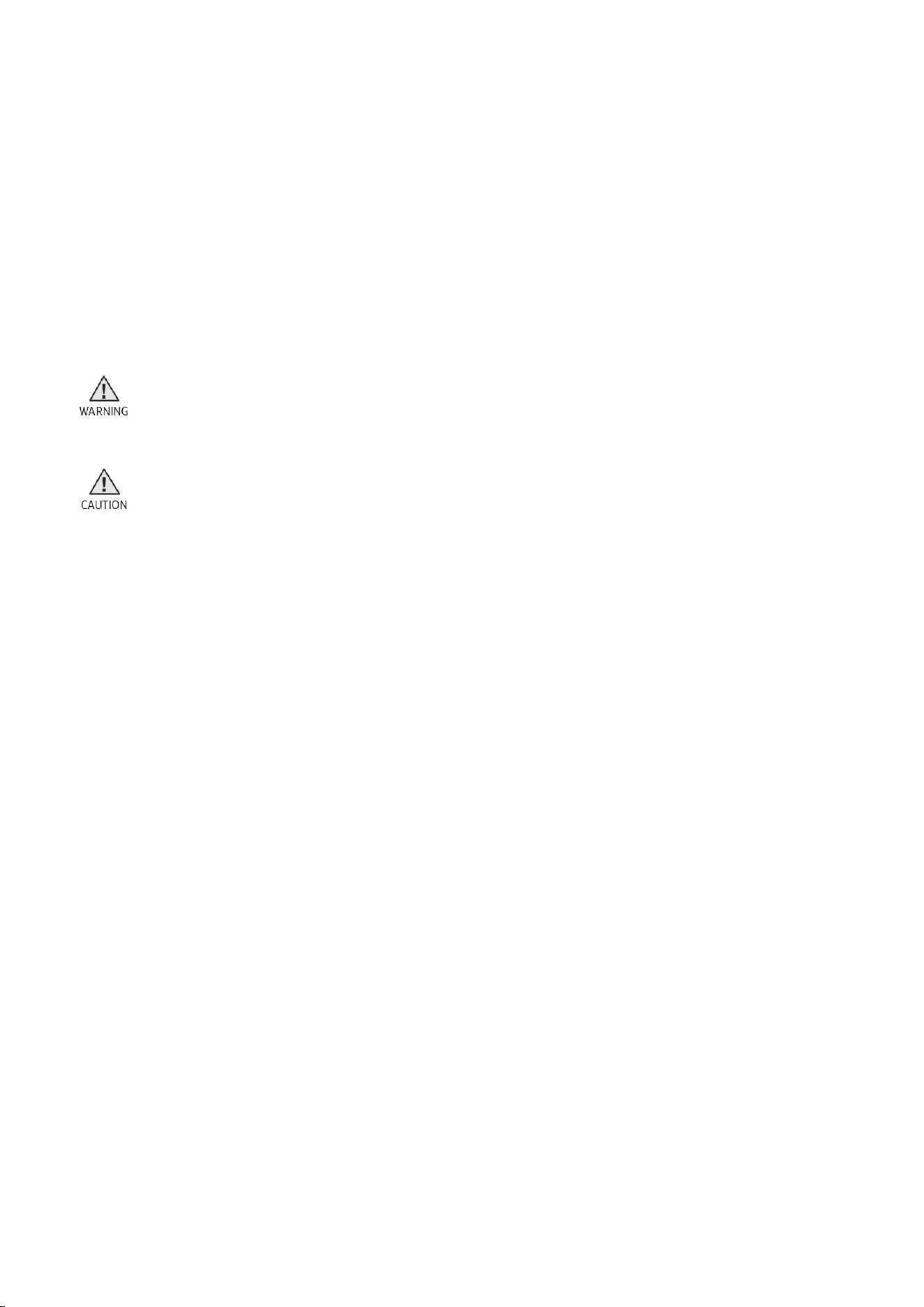
Symbol Description
Warning: Hazards or unsafe practices that may result in severe
personal injury or death
.
Caution: Hazards or unsafe practices that may result in minor personal
injury or property damage.
5
Disassembly and Reassembly
Be sure to wear protective equipment for your safety when repairing a
product.
Be sure to proceed with disassembly while fixing the product on a flat
surface.
This is a standard disassembly diagram and may differ from the actual
product.
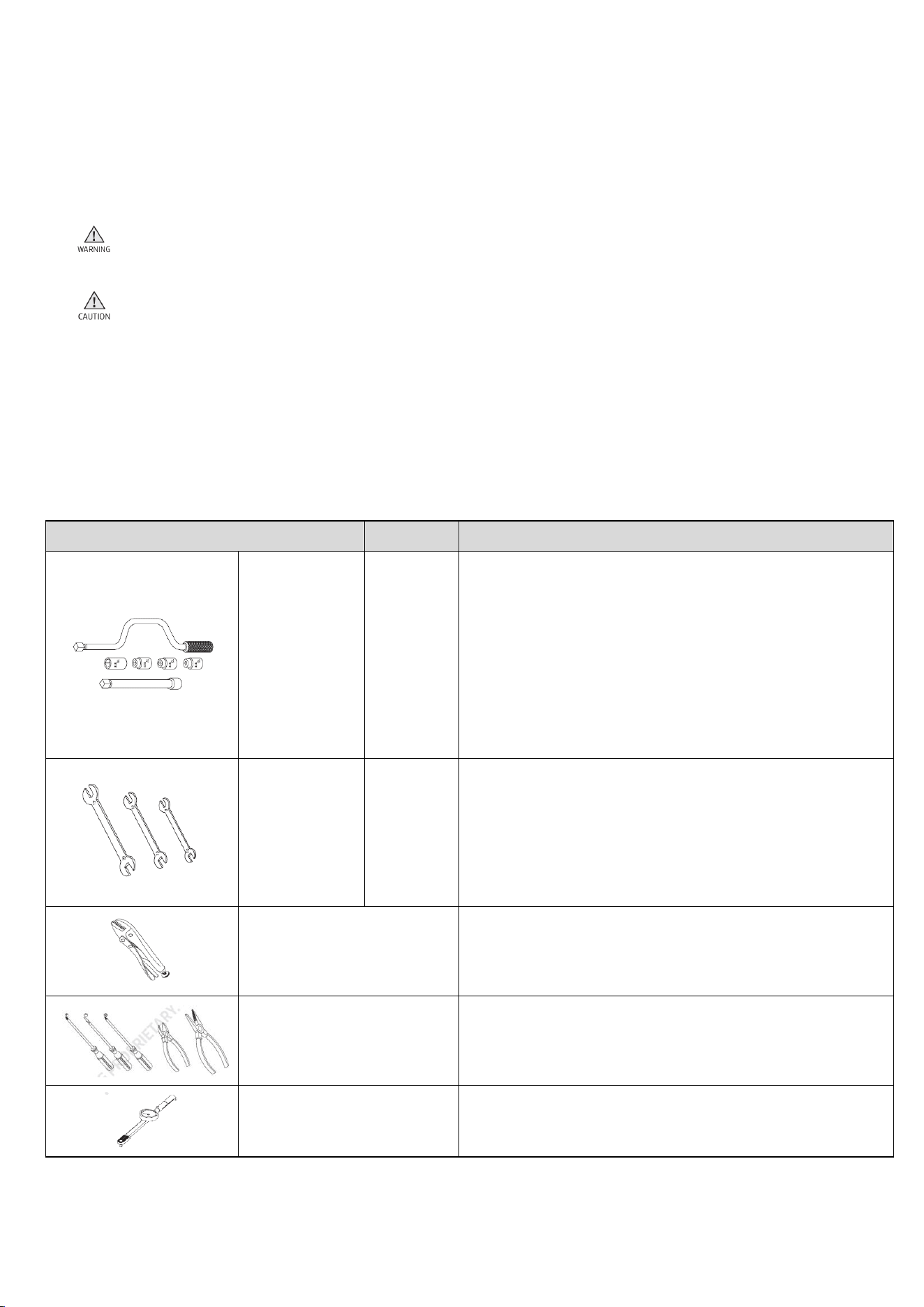
Tools Disassembly and Reassembly
Tool
Type
Remarks
Box driver
10mm
13mm
19mm
Heater(1), Tub(12), Fixer screw(5), Motor(2),
Balancer(9)
Shock absorber (2holes each in left/right), Damper(2),
Damper(Friction 2)
Pulley(1)
Double-ended
spanner
10mm
13mm
19mm
Replaced by box driver
Leg
Vice pliers
A Tool for protecting empty turning of bolt or
abrasion from using box driver
For disassembly of spin drum
Others
(Screwdriver, Nipper, Long
nose pliers)
Common tools for servicing
Torque wrench
The Tool for assembly of heater and tub

6
Standard Disassembly and Reassembly Drawings
Number Part Name
1 Assy Diaphragm
2 Door Lock
3 Assy Pump Drain
4 Heater Wash
5 Assy PBA
7
2.2.1 Assy Diaphragm
Disassembly
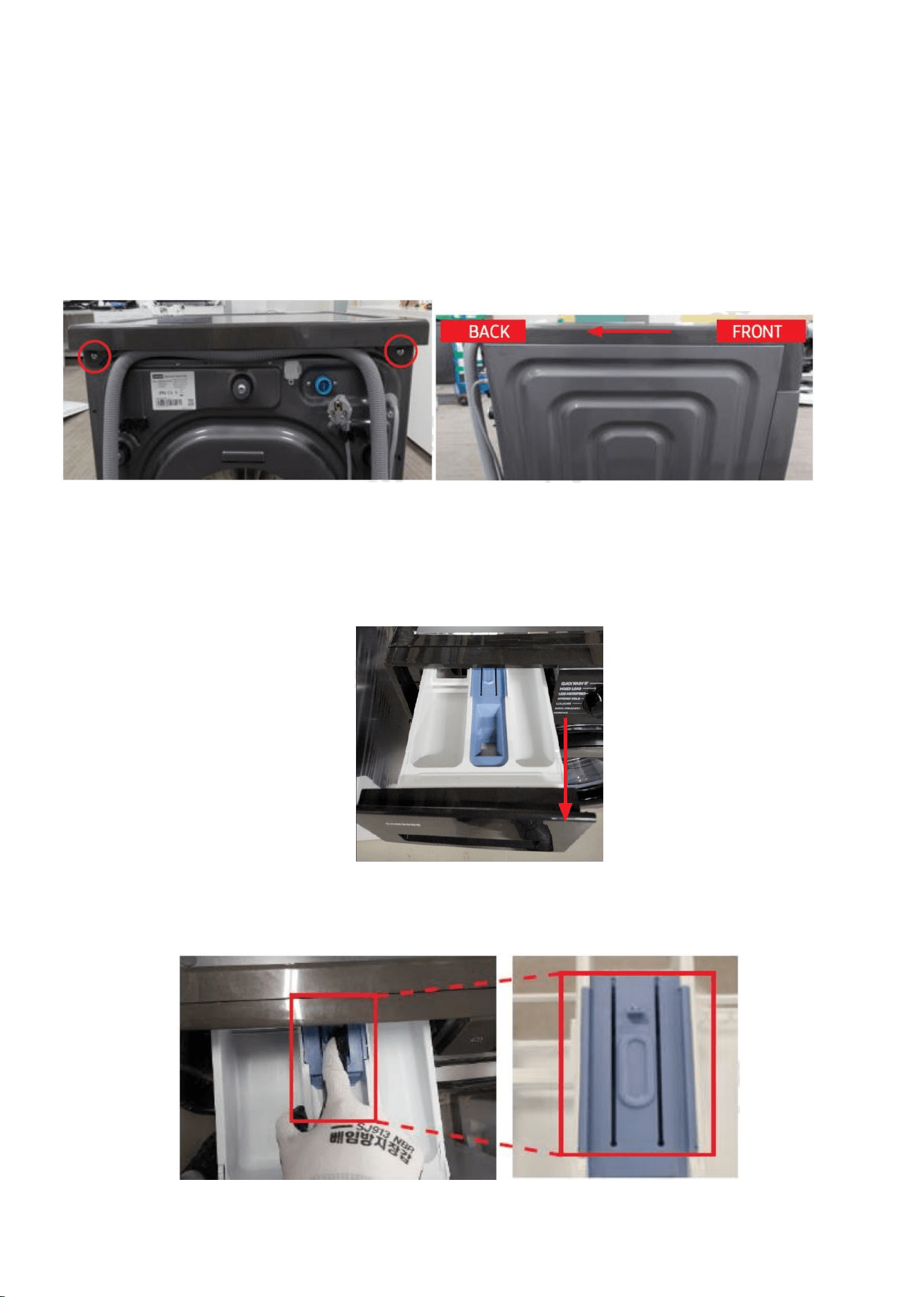
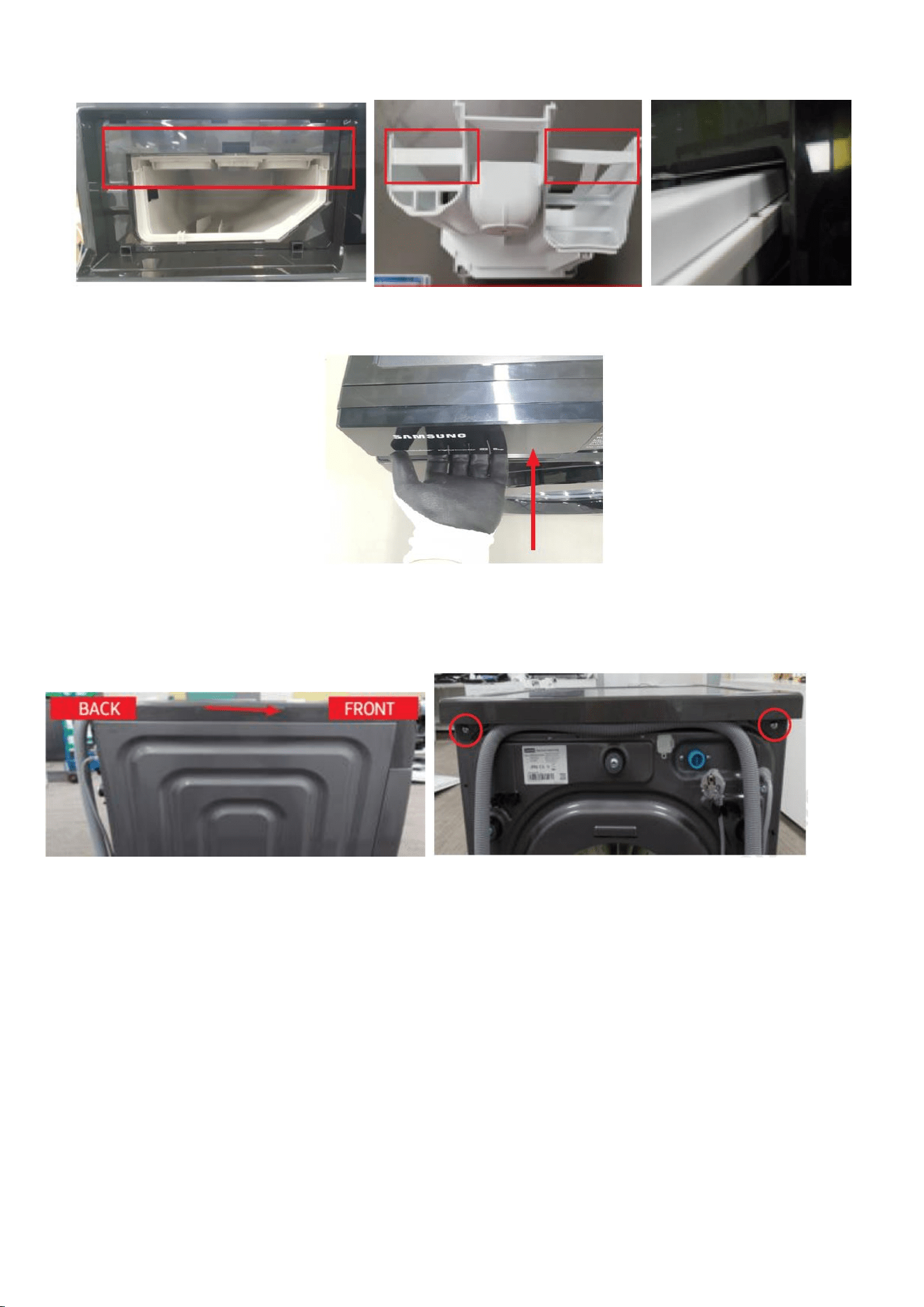
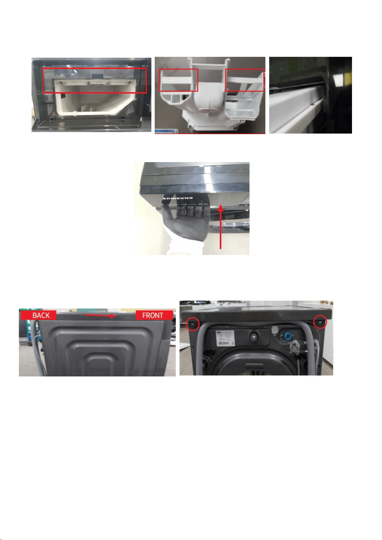
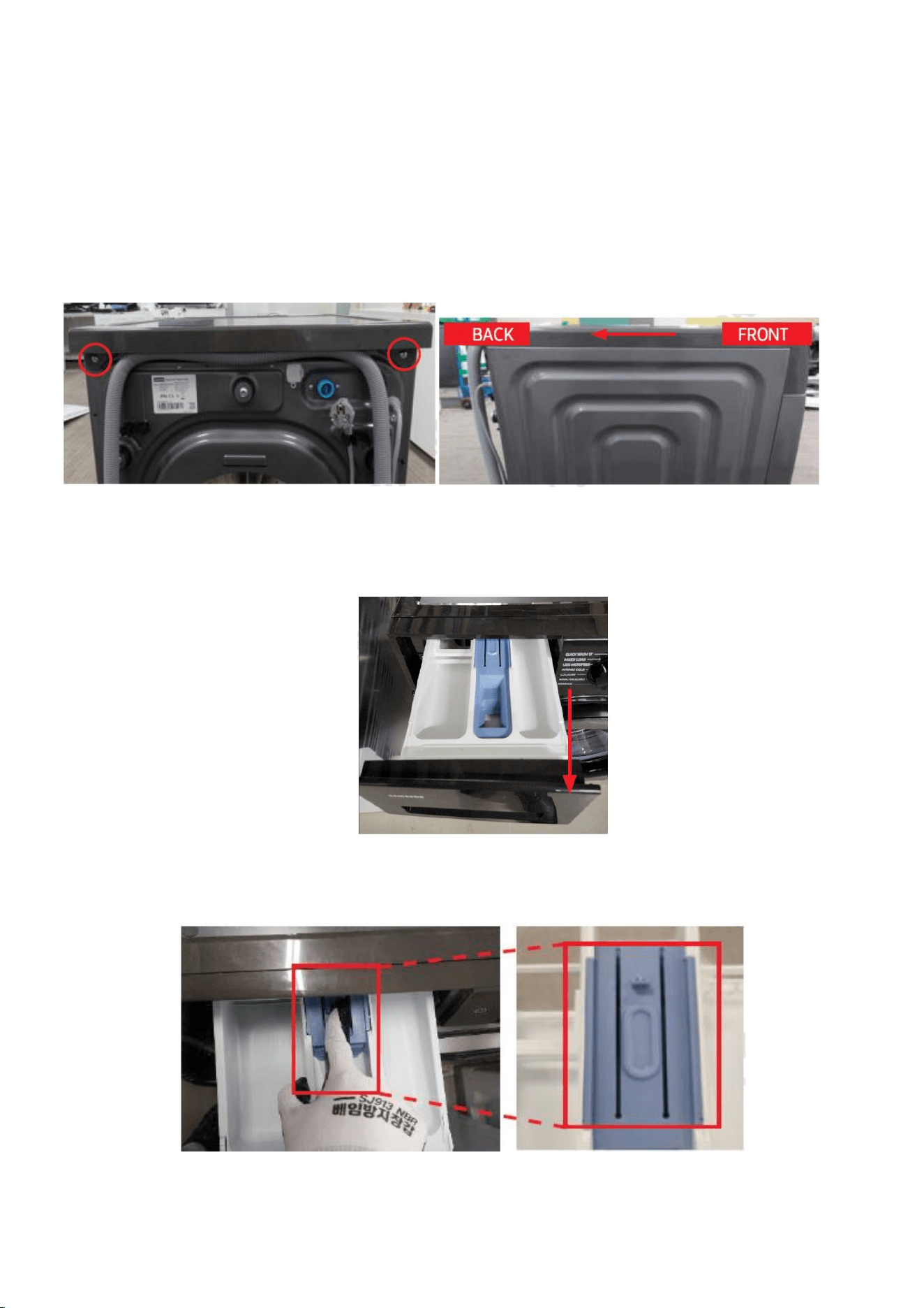
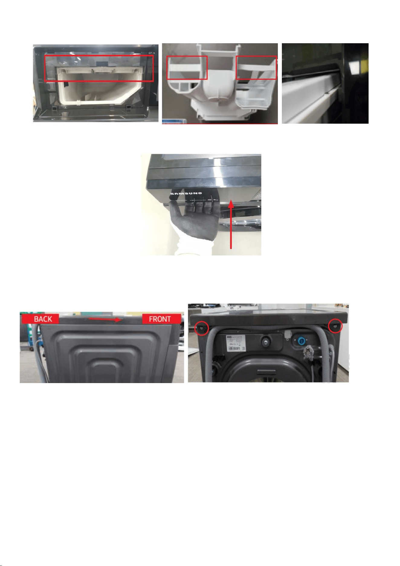
1. Remove 2 screws holding the Cover Top at the back of the unit using (+)
screw driver.
1-1. Remove the Cover Top by lifting it up after pulling it back about 15mm.
2. Open the Drawer by hand.
2-1. While holding down the release lever inside the drawer (Red box),
slide open the drawer.
8
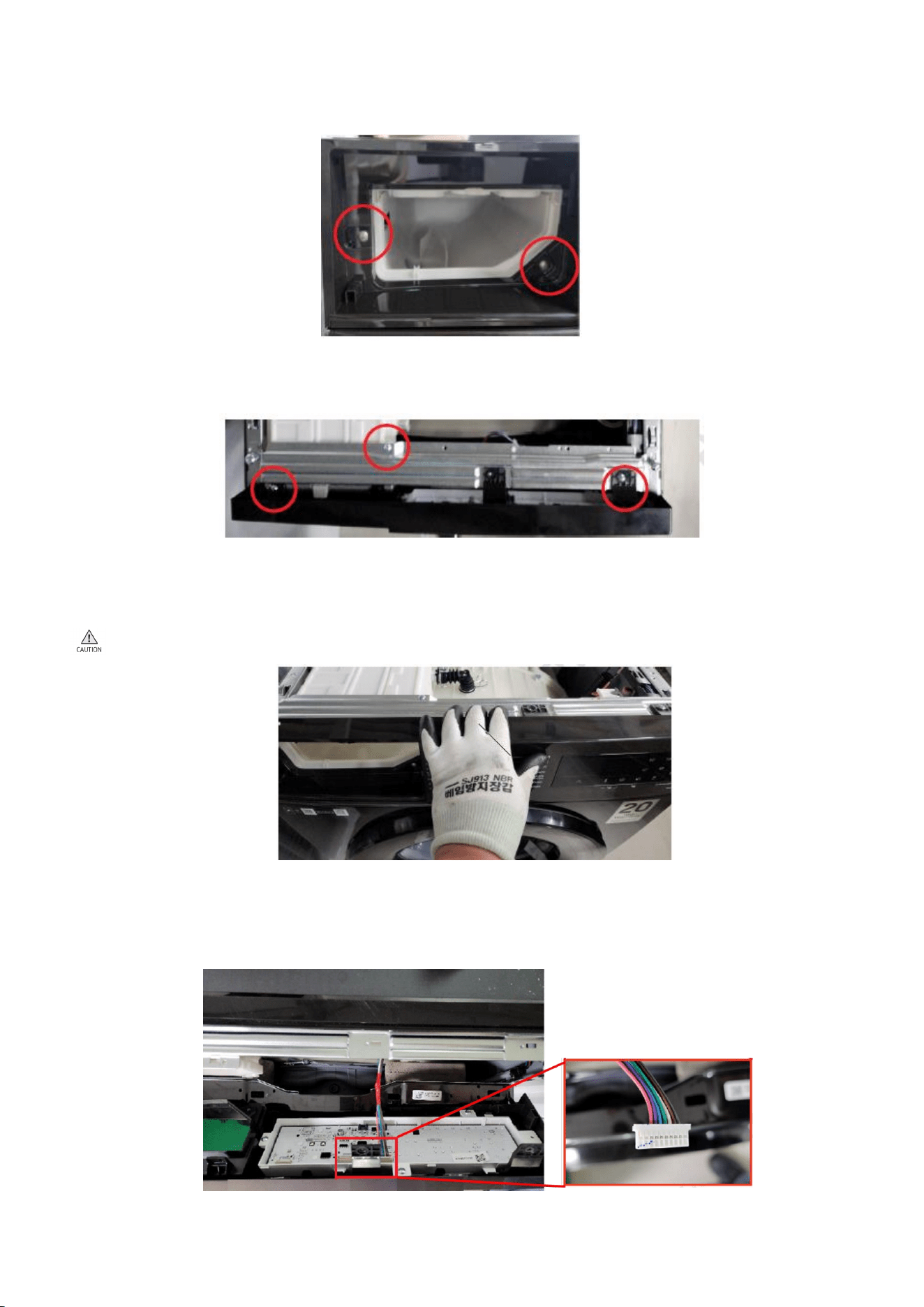
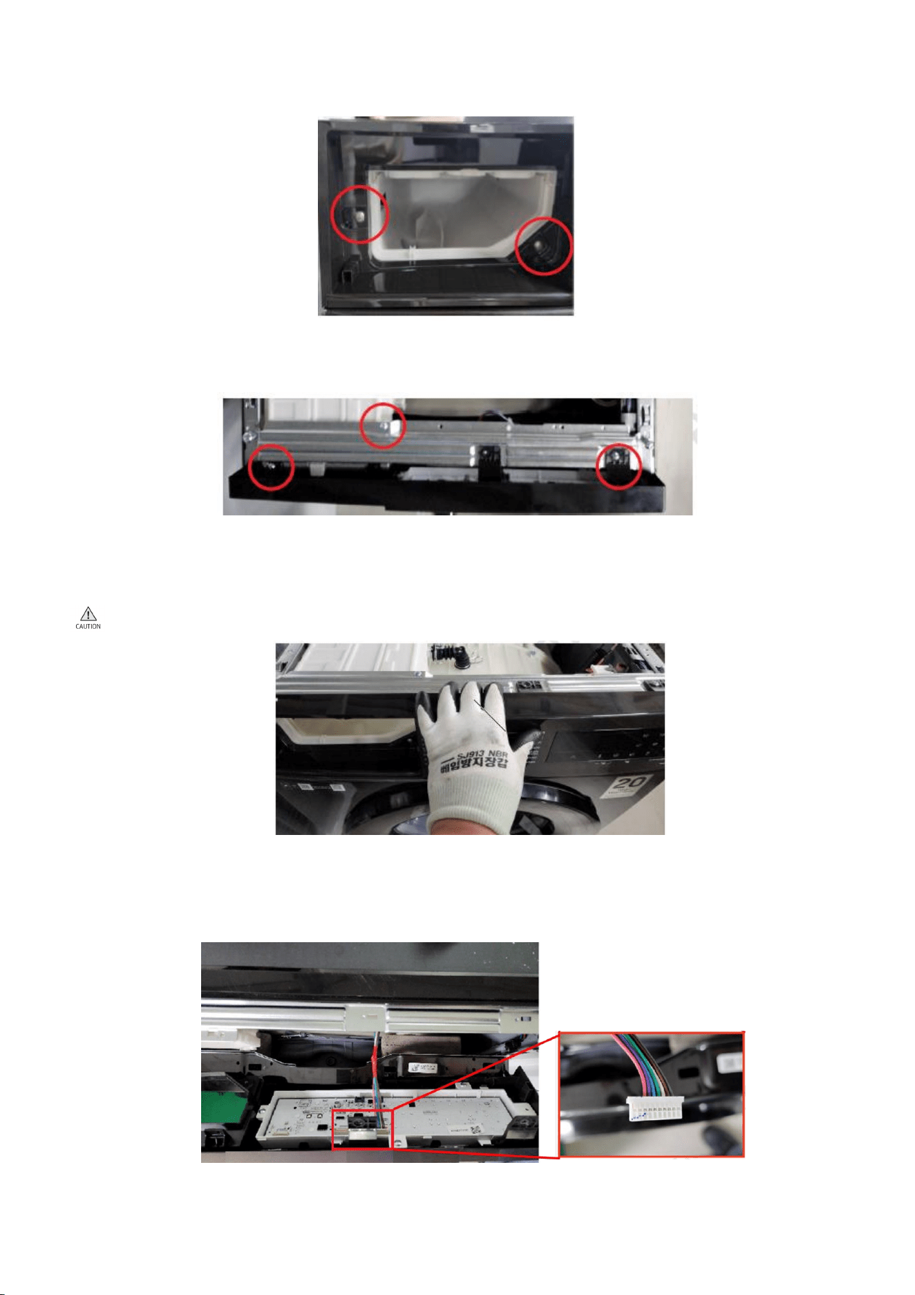
3. Remove the screws holding the Drawer and Panel using (+) screw driver.
3-1. Remove the screws at the top of the Assy Panel Control using (+) screw
driver. (3ea)
3-2. Grab the Panel and slightly push the Housing Drawer to remove the hook
and pull the Panel upwards to disassemble with body.
Be careful not to break the hook.
3-3. Hold the Assy Panel Control while unlocking the hooks and disassemble
the terminal to remove it. Press the hook while removing the terminal.
9
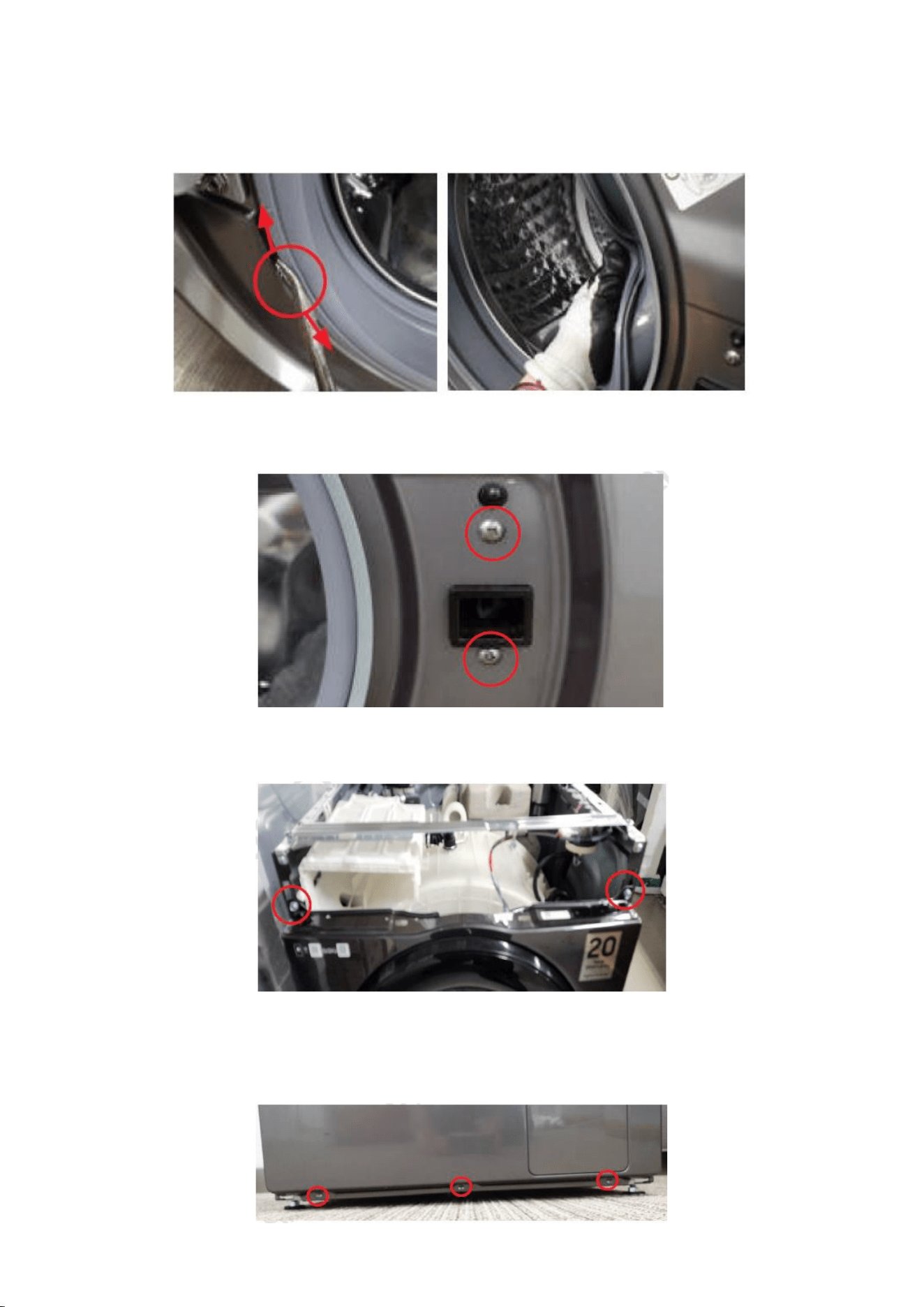
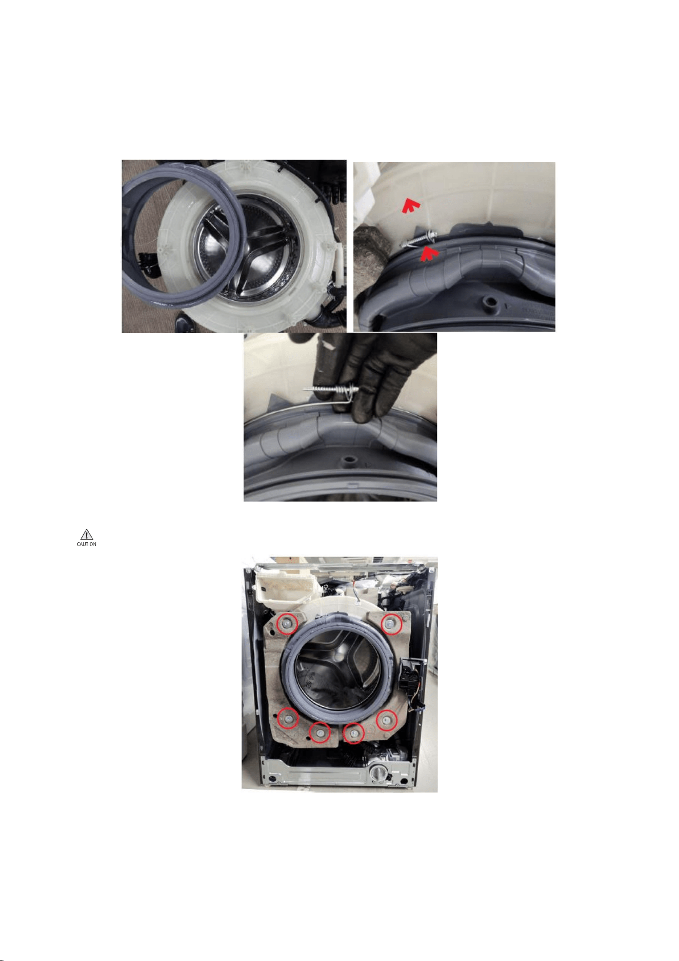
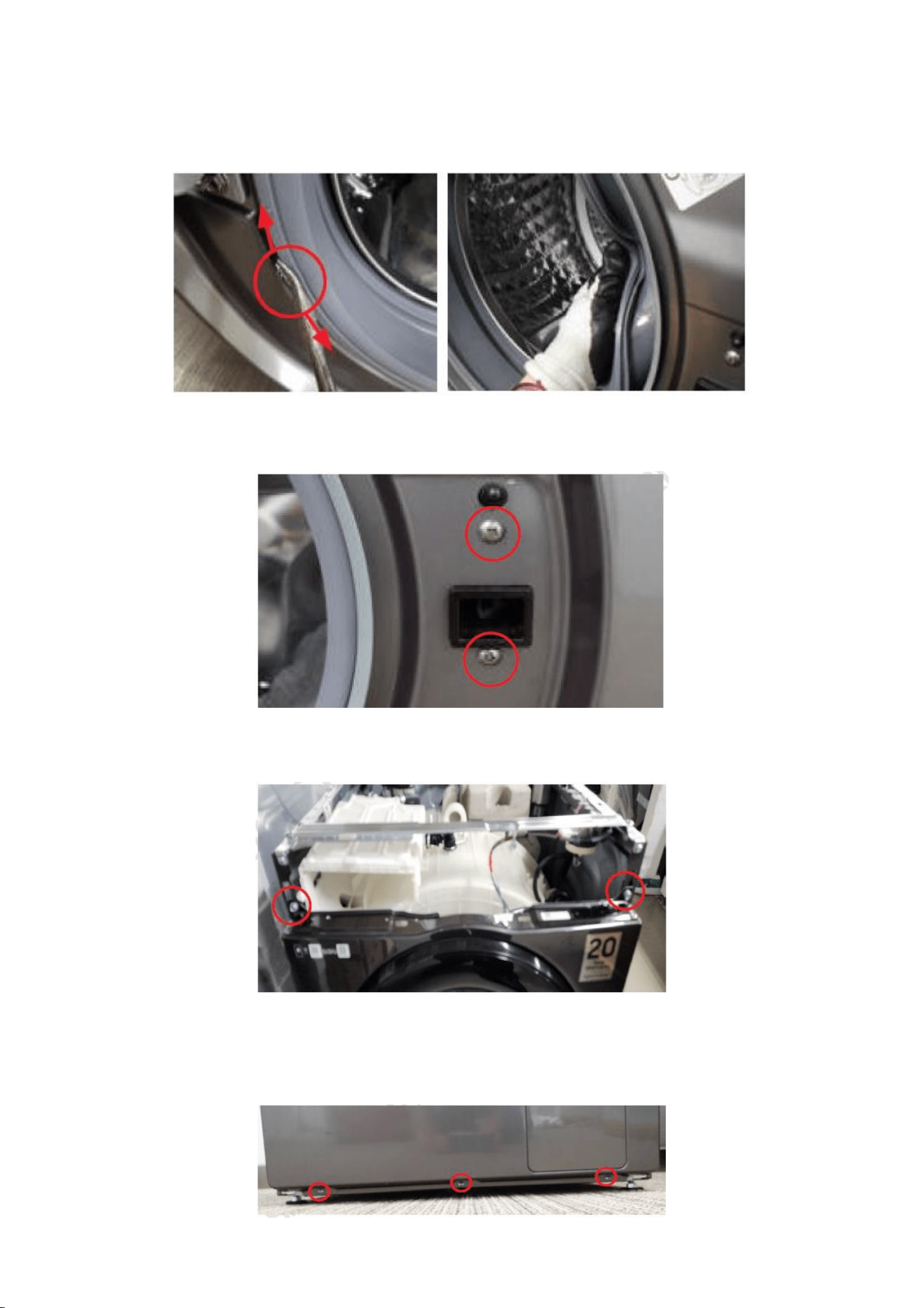
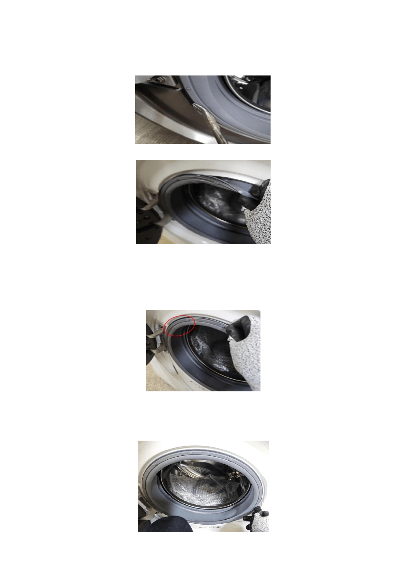
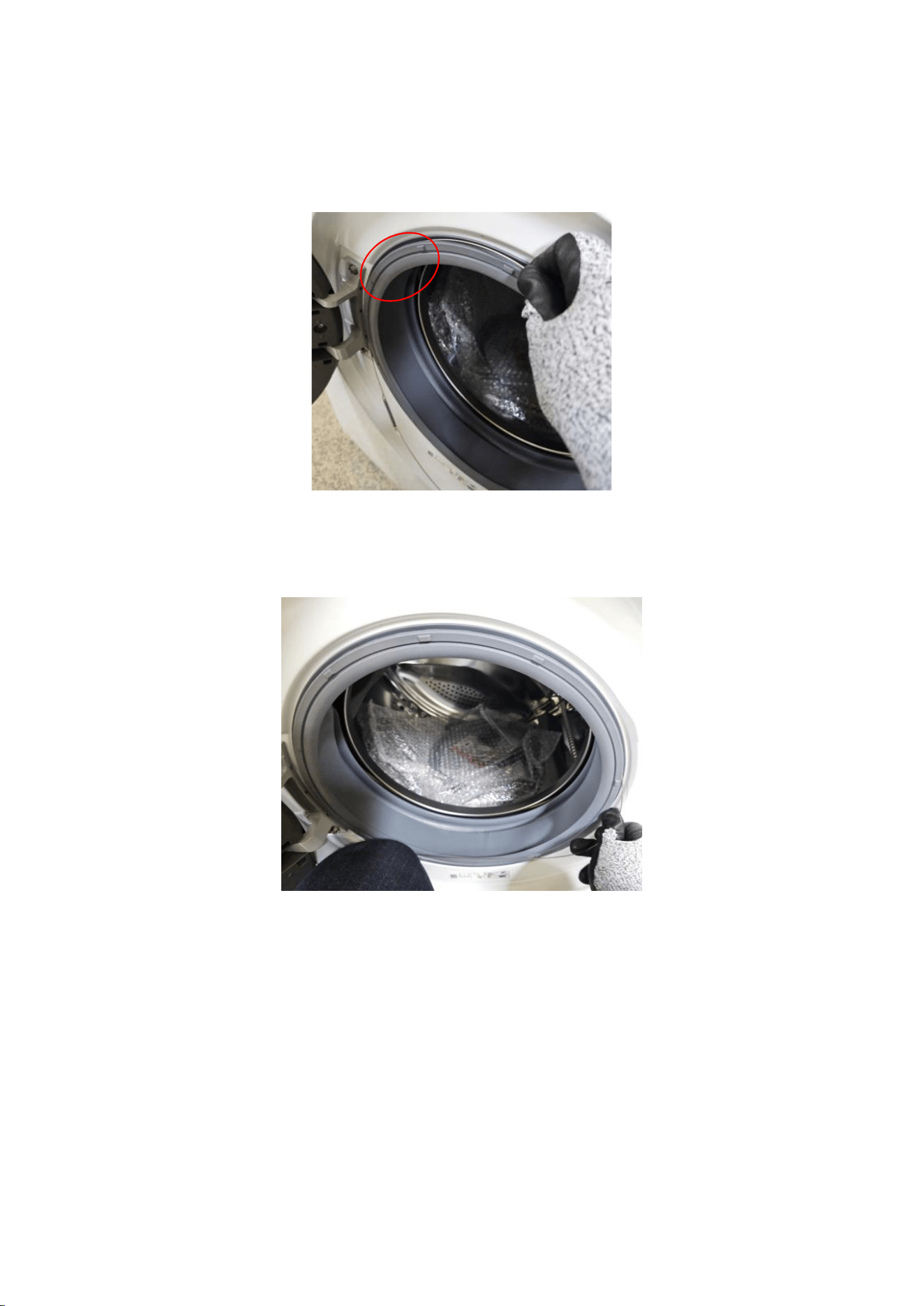
4. Using long nose pliers, pick up one of the rings on Wire-Diaphragm which
connect the spring and the wire ends. Then separate the Wire-Diaphragm
form the Frame Front and disconnect the Diaphragm.
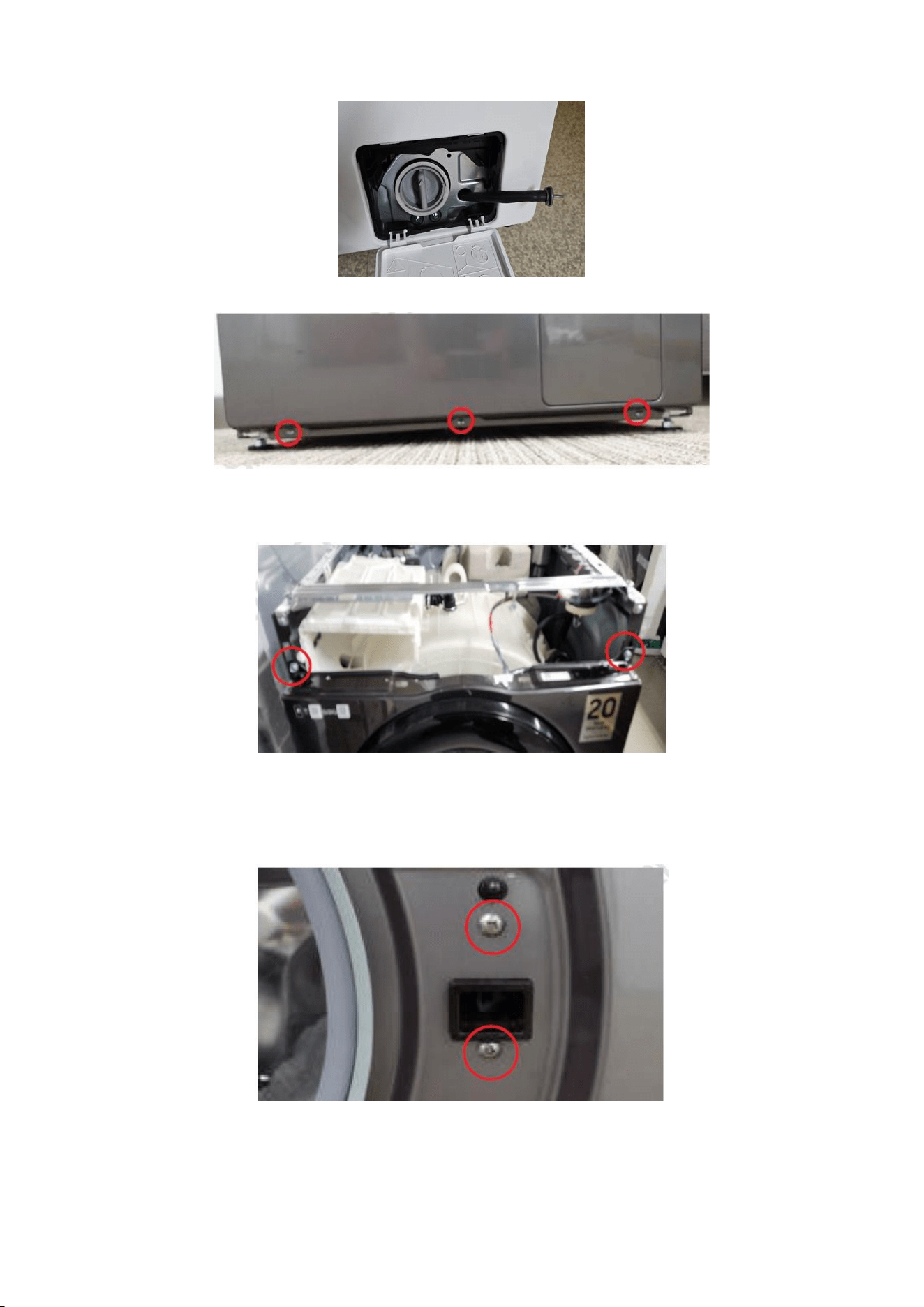
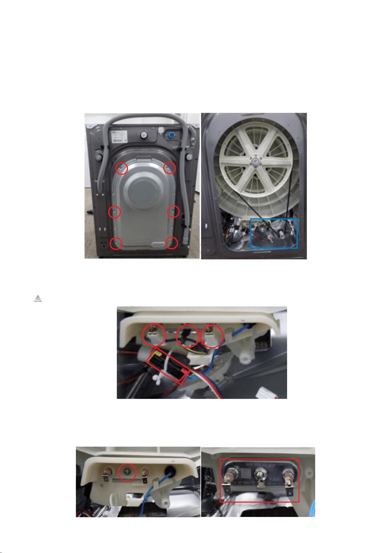
5. Remove 2 screws holding the Door Lock Switch with (+) screw driver.
5-1. Remove 2 screws holding the Frame Front with (+) screw driver.
5-2. Remove 3 screws holding the bottom of the Frame Front with (+) screw
driver.
10
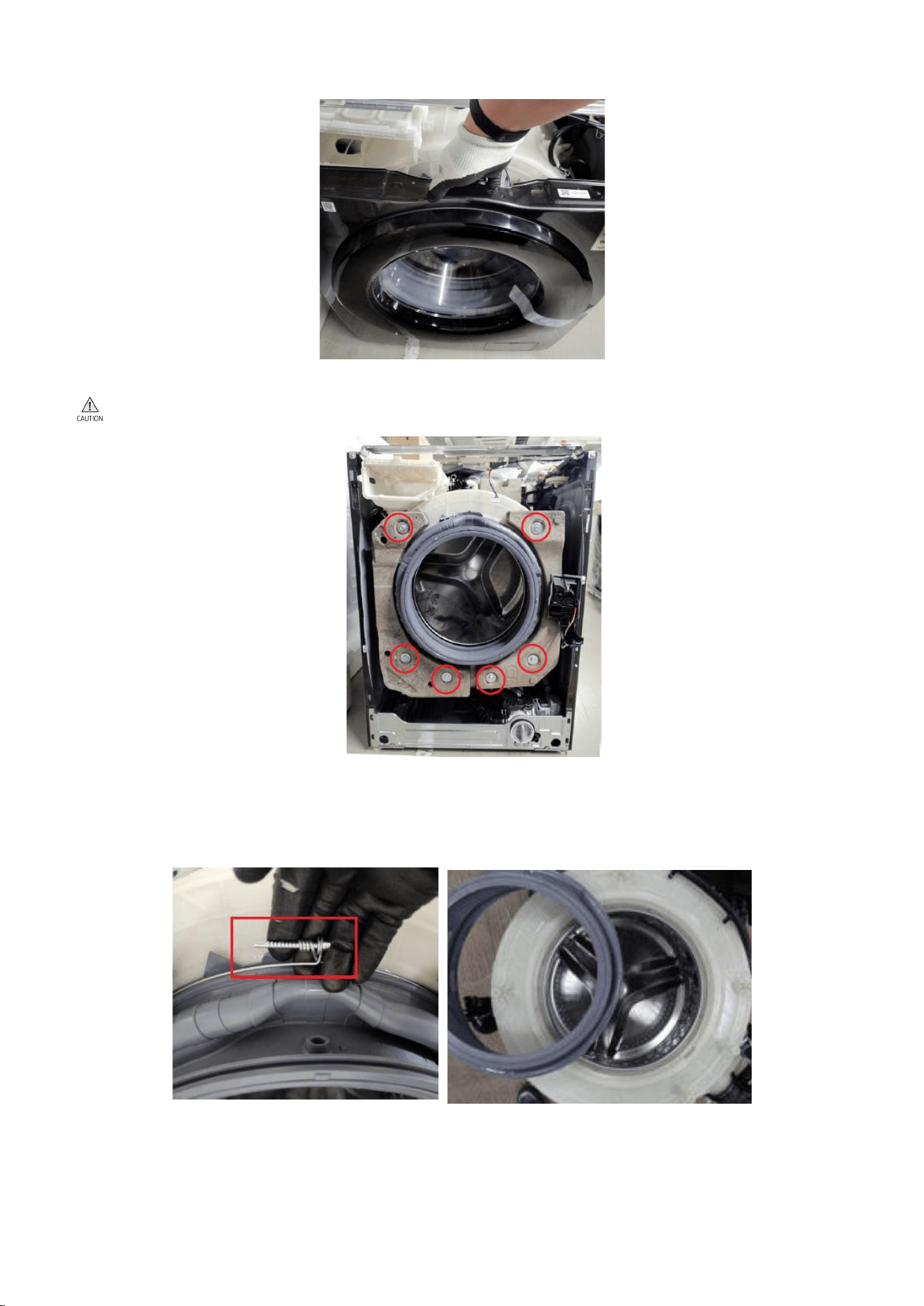
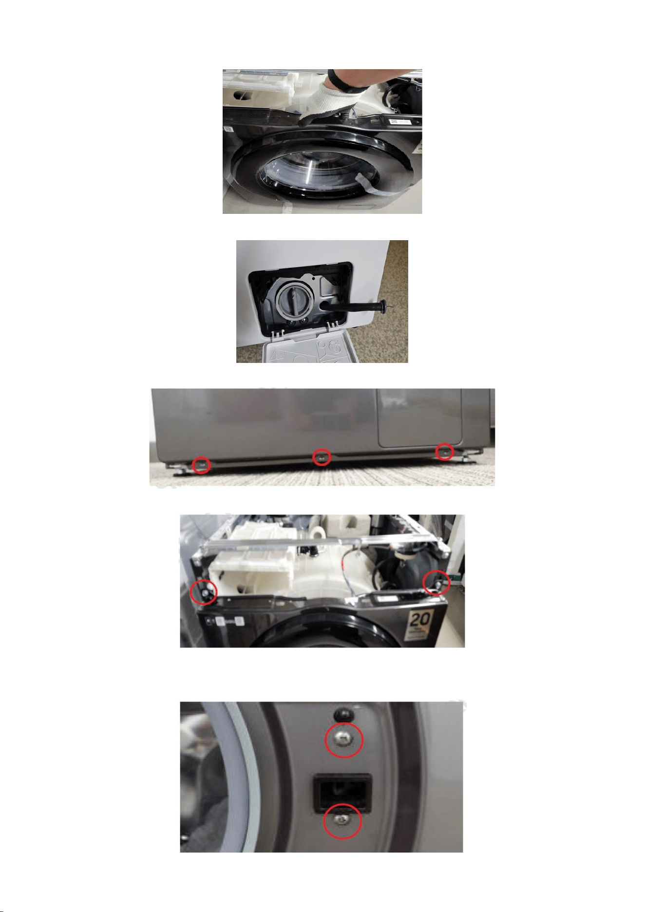
5-3. Lift Frame Front up to disassemble.
6. Remove 6 bolts each holding Weight Balancer using box driver (13mm).
Weight Balancer are heavy, be aware of any injuries.
7. Remove Wire Diaphragm by using (+) screw driver.
7-1. Remove Diaphragm.
11
Reassembly
1. Assemble Wire Diaphragm and Diaphragm by using (+) screw driver. When
assembling, be aware of direction with triangles drawn in Tub and the
Diaphragm.
2. Assemble 6 bolts each holding Weight Balancers using box driver (13mm).
Weight Balancer are heavy, be aware of any injuries.
12
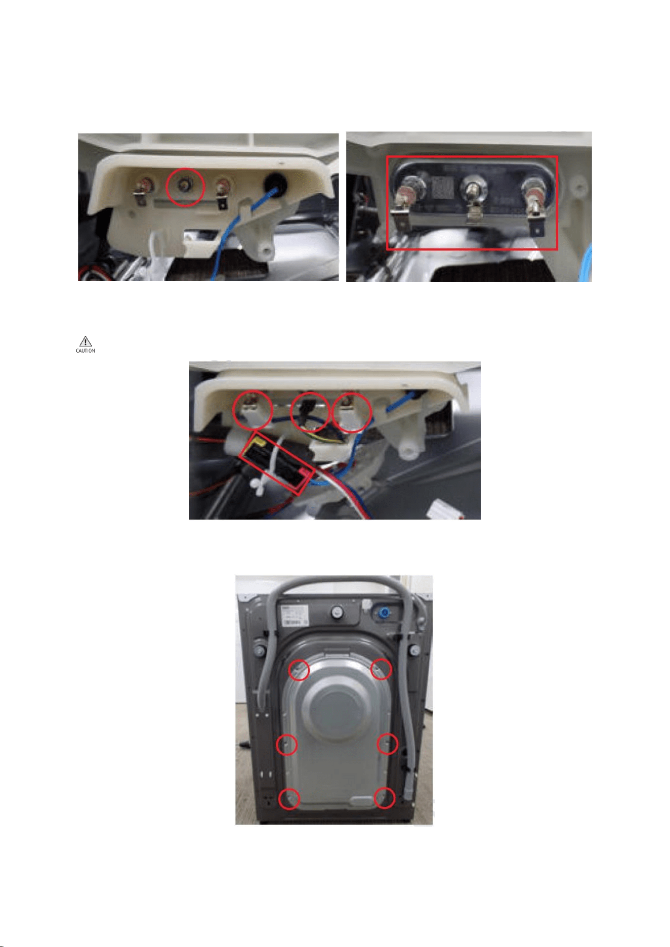
3. Put Frame Front down to assemble.
3-1. Connect the Hose of red circled place from the guide cover filter.
4. Fasten 3 screws holding the bottom of the Frame Front with (+) screw driver.
4-1. Fasten 2 screws holding the Frame Front with (+) screw driver.
4-2. Take a right position and fasten 2 screws holding the Door Lock Switch
with (+) screw driver.
13
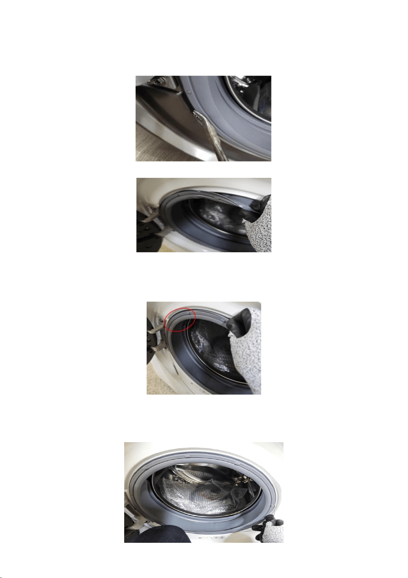
5. Assemble the wire diaphragm and Frame Front. If the wire diaphragm is loose
after assembly or is not correctly assembled at the correct position (5 o'clock
or 7 o'clock), water leakage may occur.
5-1. Insert the diaphragm into the ribs of the frame front.
5-2. Insert the diaphragm assembly ring in the 10 ~ 11 o'clock direction of the
groove surrounding the diaphragm & frame front joint.
At this time, make sure the spring faces in the 7 o'clock direction.
5-3. After fixing the 7 o'clock part so that it doesn't fall out, pull the spring of
the ring so that it stretches slightly, and insert the ring into the junction
between the diaphragm and the frame front.
14
6. Make sure to fit the rail when reassembling the Assy Drawer.
6-1. Put the Drawer in the right direction.
7. input the Cover Top by push it front
Assemble 2 screws holding the Cover Top at the back of the unit using
(+) screw driver.

15
2.2.2 Door Lock
Disassembly
1. Remove 2 screws holding the Cover Top at the back of the unit using (+)
screw driver.
1-1. Remove the Cover Top by lifting it up after pulling it back about 15mm.
2. Open the Drawer by hand.
2-1. While holding down the release lever inside the drawer (Red box), slide
open the drawer.

16
3. Remove the screws holding the Drawer and Panel using (+) screw driver.
3-1. Remove the screws at the top of the Assy Panel Control using (+) screw
driver. (3ea)
3-2. Grab the Panel and slightly push the Housing Drawer to remove the hook
and pull the Panel upwards to disassemble with body.
Be careful not to break the hook.
3-3. Hold the Assy Panel Control while unlocking the hooks and disassemble
the terminal to remove it. Press the hook while removing the terminal.
17
4. Using long nose pliers, pick up one of the rings on Wire-Diaphragm which
connect the spring and the wire ends. Then separate the Wire-Diaphragm
form the Frame Front and disconnect the Diaphragm.
5. Remove 2 screws holding the Door Lock Switch with (+) screw driver.
5-1. Remove 2 screws holding the Frame Front with (+) screw driver.
5-2. Remove 3 screws holding the bottom of the Frame Front with (+) screw
driver.
18
5-3. Lift Frame Front up to disassemble.
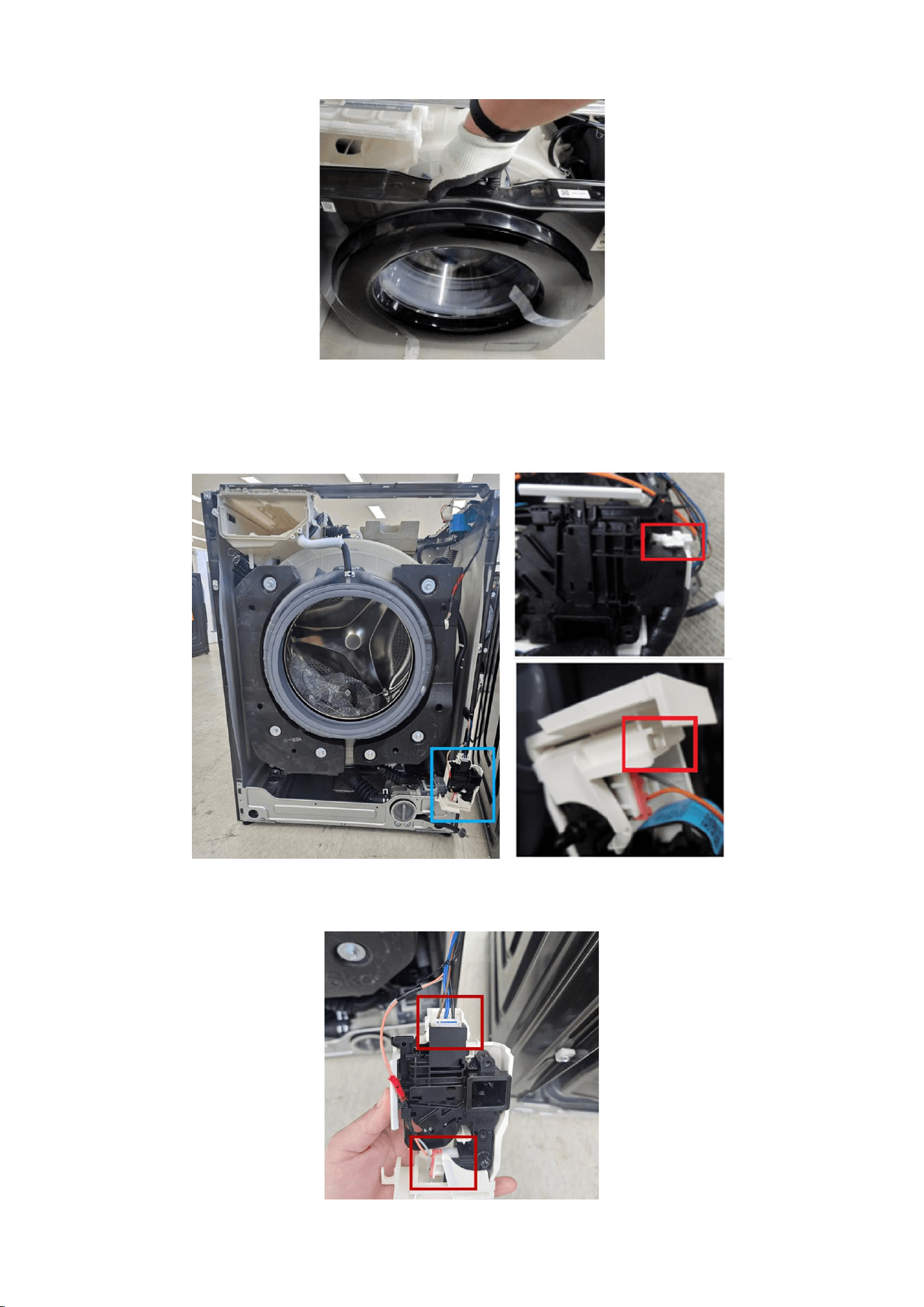
6. Remove Cover Door Switch (blue box) by gently pushing the red box part
with (-) screw driver.
6-1. Disassemble the terminals 2ea.
19
Reassembly
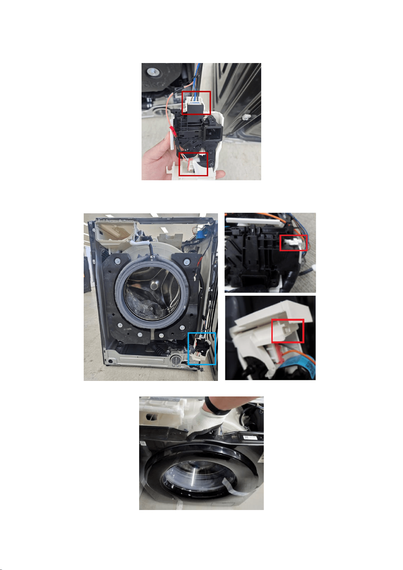
1. Assemble the terminals. (2ea)
1-1. Assemble the Cover Door Switch by gently pushing the red box part with
hand.
2. Put Frame Front down to assemble.
20
2-1. Connect the Hose of red circled place from the guide cover filter.
3. Fasten 3 screws holding the bottom of the Frame Front with (+) screw driver.
3-1. Fasten 2 screws holding the Frame Front with (+) screw driver.
3-2. Take a right position and fasten 2 screws holding the Door Lock Switch with
(+) screw driver.
21
4. Assemble the wire diaphragm and Frame Front. If the wire diaphragm is loose
after assembly or is not correctly assembled at the correct position (5 o'clock
or 7 o'clock), water leakage may occur.
4-1. Insert the diaphragm into the ribs of the frame front.
4-2.
Insert the diaphragm assembly ring in the 10 ~ 11 o'clock direction of the groove
surrounding the diaphragm & frame front joint.
At this time, make sure the spring faces in the 7 o'clock direction.
4-3. After fixing the 7 o'clock part so that it doesn't fall out, pull the spring of the
ring so that it stretches slightly, and insert the ring into the junction between the
diaphragm and the frame front.
22
5. Make sure to fit the rail when reassembling the Assy Drawer.
5-1. Put the Drawer in the right direction.
6. input the Cover Top by push it front
Assemble 2 screws holding the Cover Top at the back of the unit using
(+) screw driver.
23
2.2.3 Assy Pump Drain
Disassembly
1. Remove 2 screws holding the Cover Top at the back of the unit using (+)
screw driver.
1-1. Remove the Cover Top by lifting it up after pulling it back about 15mm.
2. Open the Drawer by hand.
2-1. While holding down the release lever inside the drawer (Red box), slide open
the drawer.
24
3. Remove the screws holding the Drawer and Panel using (+) screw driver.
3-1. Remove the screws at the top of the Assy Panel Control using (+) screw
driver. (3ea)
3-2. Grab the Panel and slightly push the Housing Drawer to remove the hook
and pull the Panel upwards to disassemble with body.
Be careful not to break the hook.
3-3. Hold the Assy Panel Control while unlocking the hooks and disassemble the
terminal to remove it. Press the hook while removing the terminal.

25
4. Using long nose pliers, pick up one of the rings on Wire-Diaphragm which
connect the spring and the wire ends. Then separate the Wire-Diaphragm
form the Frame Front and disconnect the Diaphragm.
5. Remove 2 screws holding the Door Lock Switch with (+) screw driver.
5-1. Remove 2 screws holding the Frame Front with (+) screw driver.
5-2. Remove 3 screws holding the bottom of the Frame Front with (+) screw
driver.
26
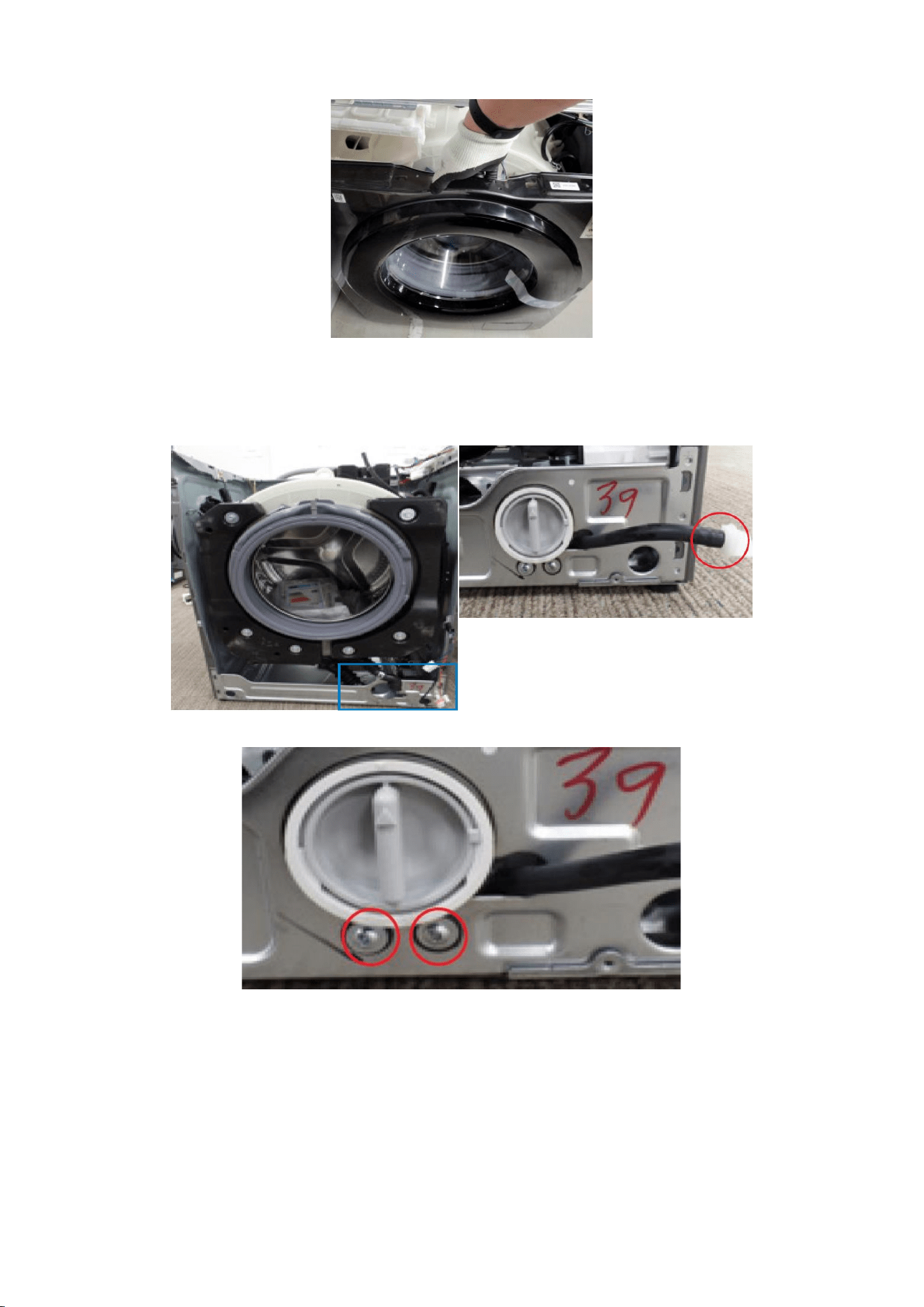
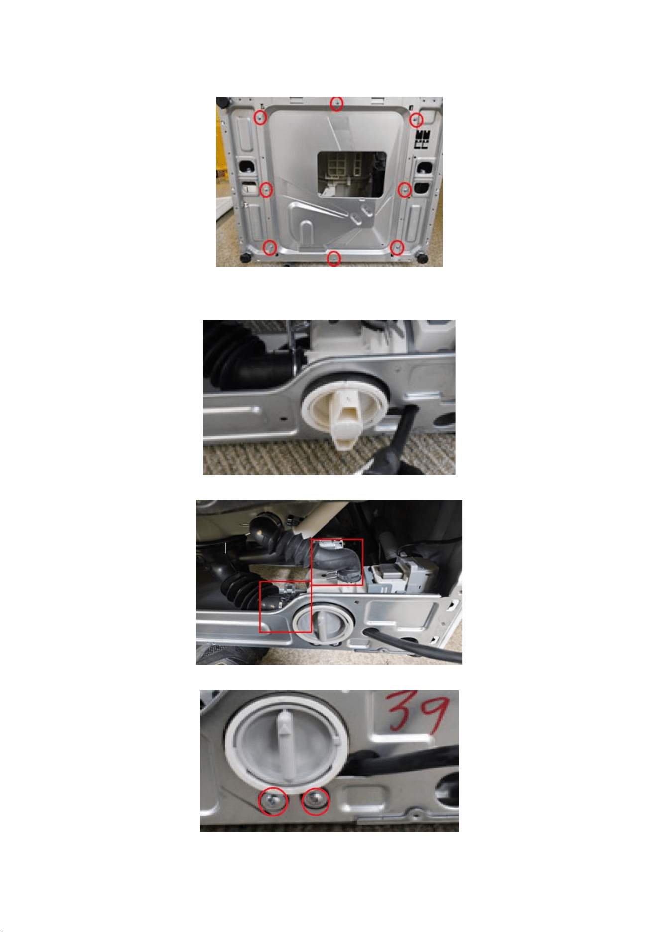
5-3. Lift Frame Front up to disassemble.
6. The Pump is located in the blue box. Remove the remaining water through
the drainage hose. Place a bowl under the drainage hose to catch any water
that may flow out.
7. Remove 2 screws holding the drain pump using (+) screw driver.
27
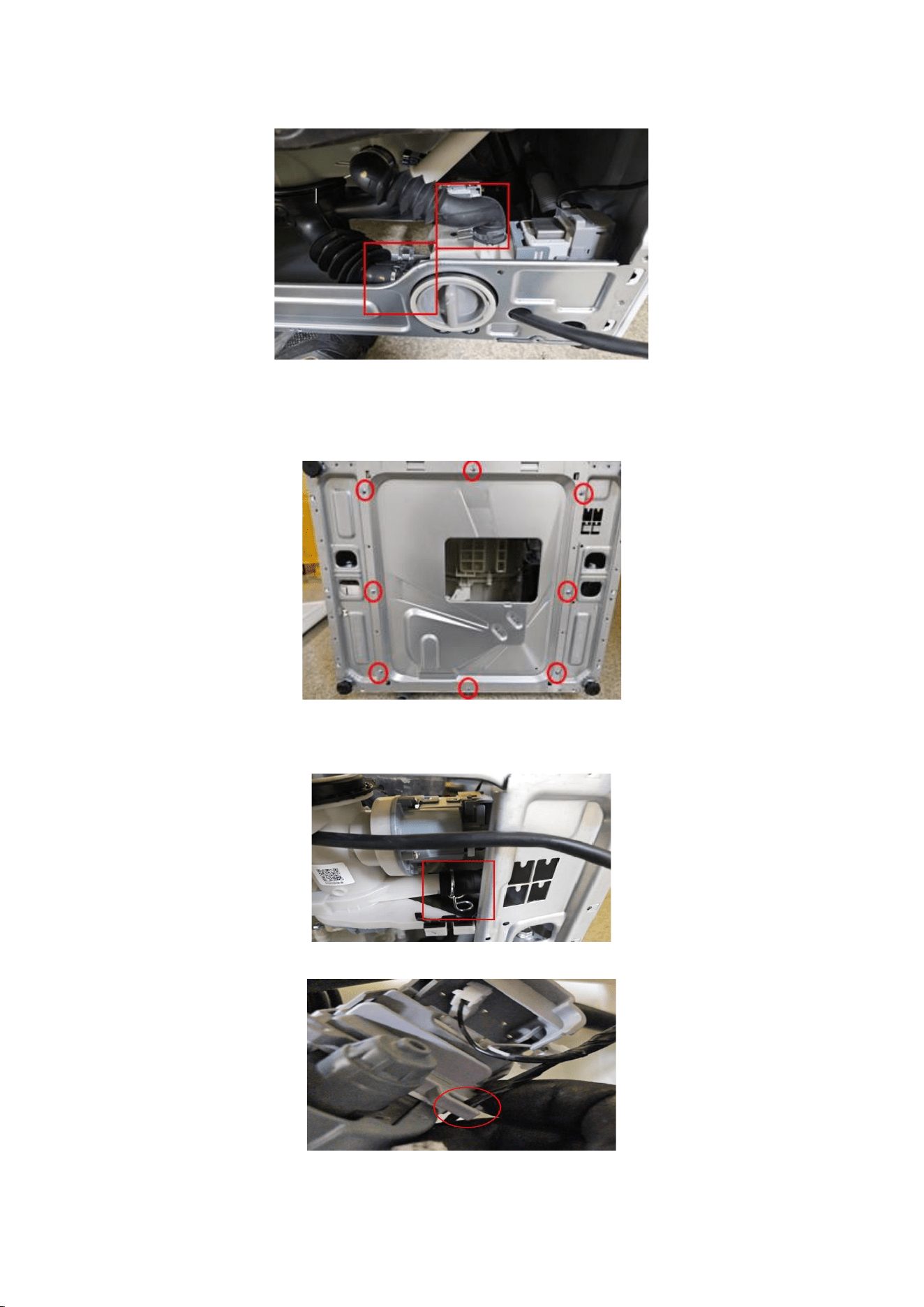
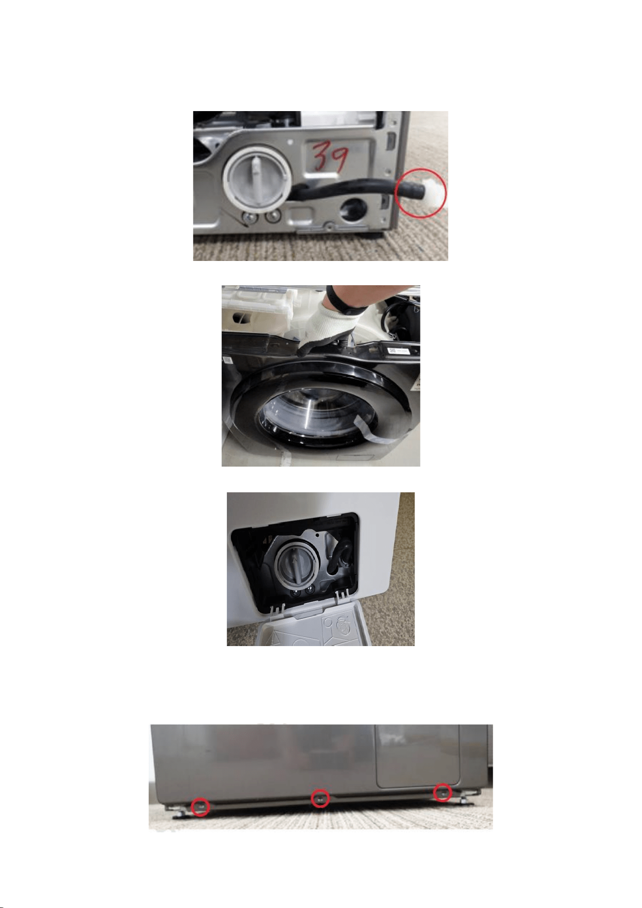
8. Separate the Hose & Clamper of red box, from the assy pump drain.
9. Remove 8 screws holding the cover bottom and frame plate bottom
with (+) screw driver.
10. Separate the Hose & Clamper of red box, from the assy pump drain
Slightly take the pump out from the frame.
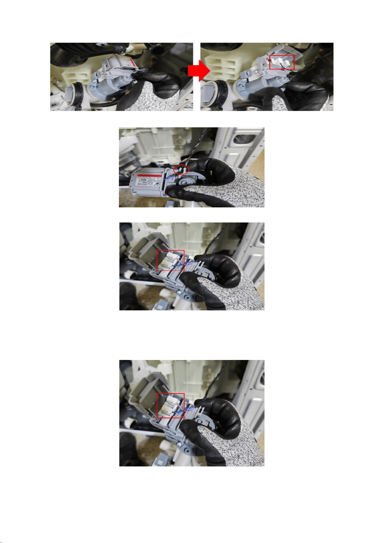
10-1. Separate the Wire of red circled place, from the bubble pump.
28
10-2. pen the case, Separate the 2 Wire of red box, from the bubble pump.
10-3. Separate the Wire of red circled place, from the drain pump.
10-4. Open the case, Separate the 2 Wire of red box, from the drain pump.
Reassembly
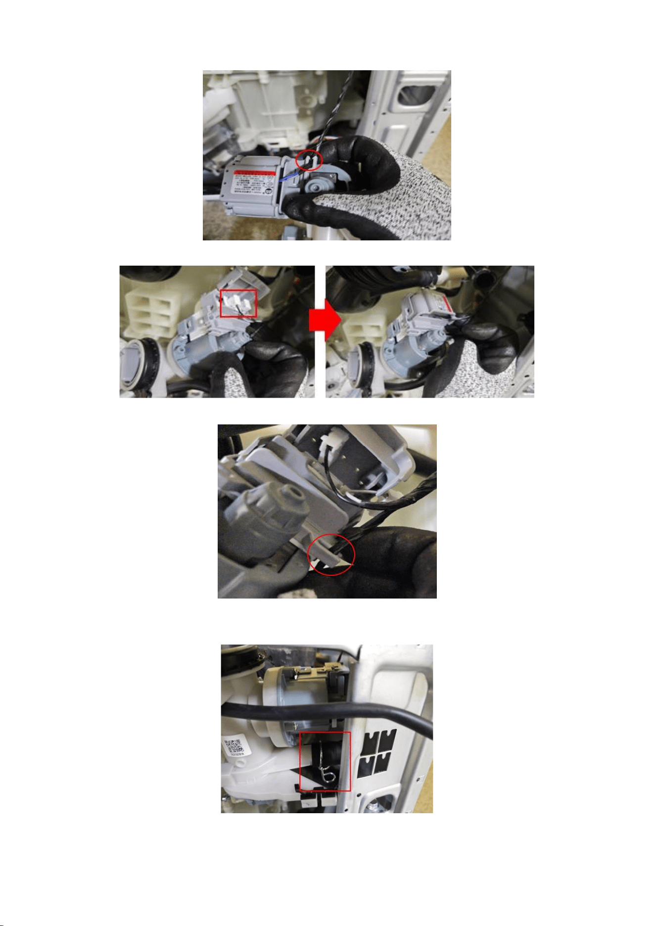
1. Connect the 2 Wire of red box, from the drain pump.
29
1-1. Close the case, Connect the Wire of red circled place, from the drain pump.
1-2. Connect the 2 Wire of red box, from the bubble pump, Close the case.
1-3. Connect the Wire of red circled place, from the bubble pump.
2. Connect the Hose & Clamper of red box, from the assy pump drain
30
3. Assemble 8 screws holding the cover bottom and frame plate bottom
with (+) screw driver.
4. Assemble the pump in the right position as shown in the picture,
pull the drainage hose towards you
4-1. Connect the Hose & Clamper of red box, from the assy pump drain.
5. Assemble 2 screws holding the drain pump using (+) screw driver.
31
5-1. Assemble the drainage hose.
6. Put Frame Front down to assemble.
6-1. Connect the Hose of red circled place from the guide cover filter.
7. Fasten 3 screws holding the bottom of the Frame Front with (+) screw driver.
32
7-1. Fasten 2 screws holding the Frame Front with (+) screw driver.
7-2. Take a right position and fasten 2 screws holding the Door Lock Switch with
(+) screw driver.
8. Assemble the wire diaphragm and Frame Front. If the wire diaphragm is
loose after assembly or is not correctly assembled at the correct position (5
o'clock or 7 o'clock), water leakage may occur.
8-1. Insert the diaphragm into the ribs of the frame front.
33
8-2. Insert the diaphragm assembly ring in the 10 ~ 11 o'clock direction of the
groove surrounding the diaphragm & frame front joint.
At this time, make sure the spring faces in the 7 o'clock direction.
8-3. After fixing the 7 o'clock part so that it doesn't fall out, pull the
spring of the ring so that it stretches slightly, and insert the ring into
the junction between the diaphragm and the frame front.
34
9. Make sure to fit the rail when reassembling the Assy Drawer.
9-1. Put the Drawer in the right direction.
10. input the Cover Top by push it front
Assemble 2 screws holding the Cover Top at the back of the unit using
(+) screw driver.
35
2.2.4 Heater Wash
Disassembly
1. Remove 6 screws with (+) screw driver. Separate the Cover Back. The Heater
is located in the blue box.
2. Disconnect the Connection housing (4ea) and Holder.
Make sure the Wire harness are not getting stuck in other parts.
3. Disassemble the Heater and the nut holding the Heater using 10mm box
driver.
36
Reassembly
1. Assemble the Heater and the nut holding the heater using the 10mm box
driver.
2. Connect the Connection housing (4ea) and Holder.
Make sure the Wire harness are not getting stuck in other parts.
3. Insert the Cover Back and fasten the screws in 6 places using (+) screw driver.
37
2.2.5 Assy PBA
Disassembly
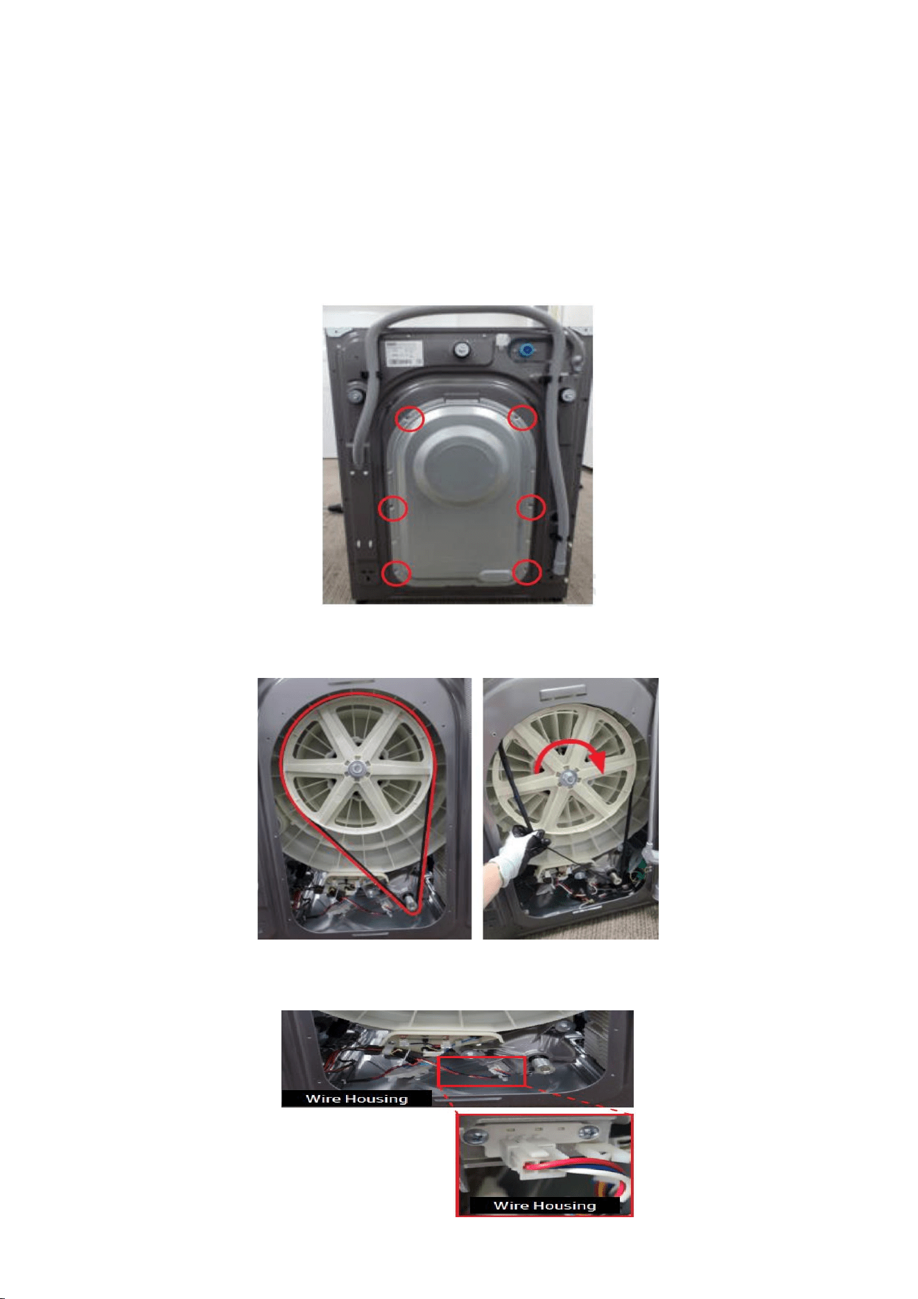
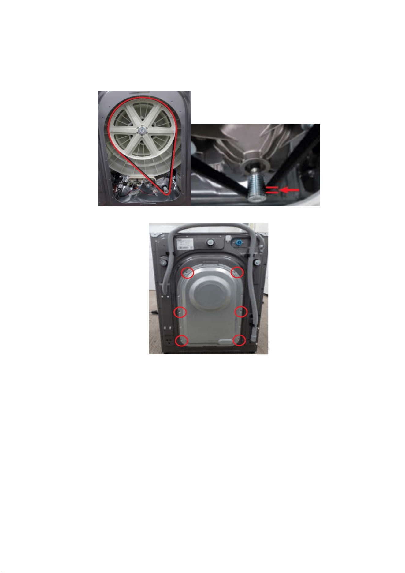
1. Remove 6 screws with (+) screw driver. Separate the Cover Back.
2. Separate the belt by pulling the belt towards your body and slowly rotate the
pulley.
3. Separate the Wire Housing from the motor by hand. Take a look at the hook
and put it in the right place
38
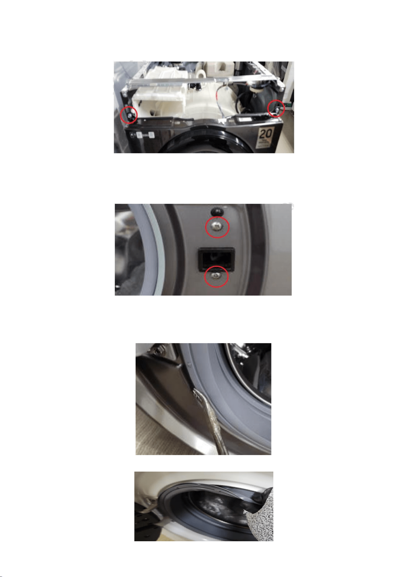
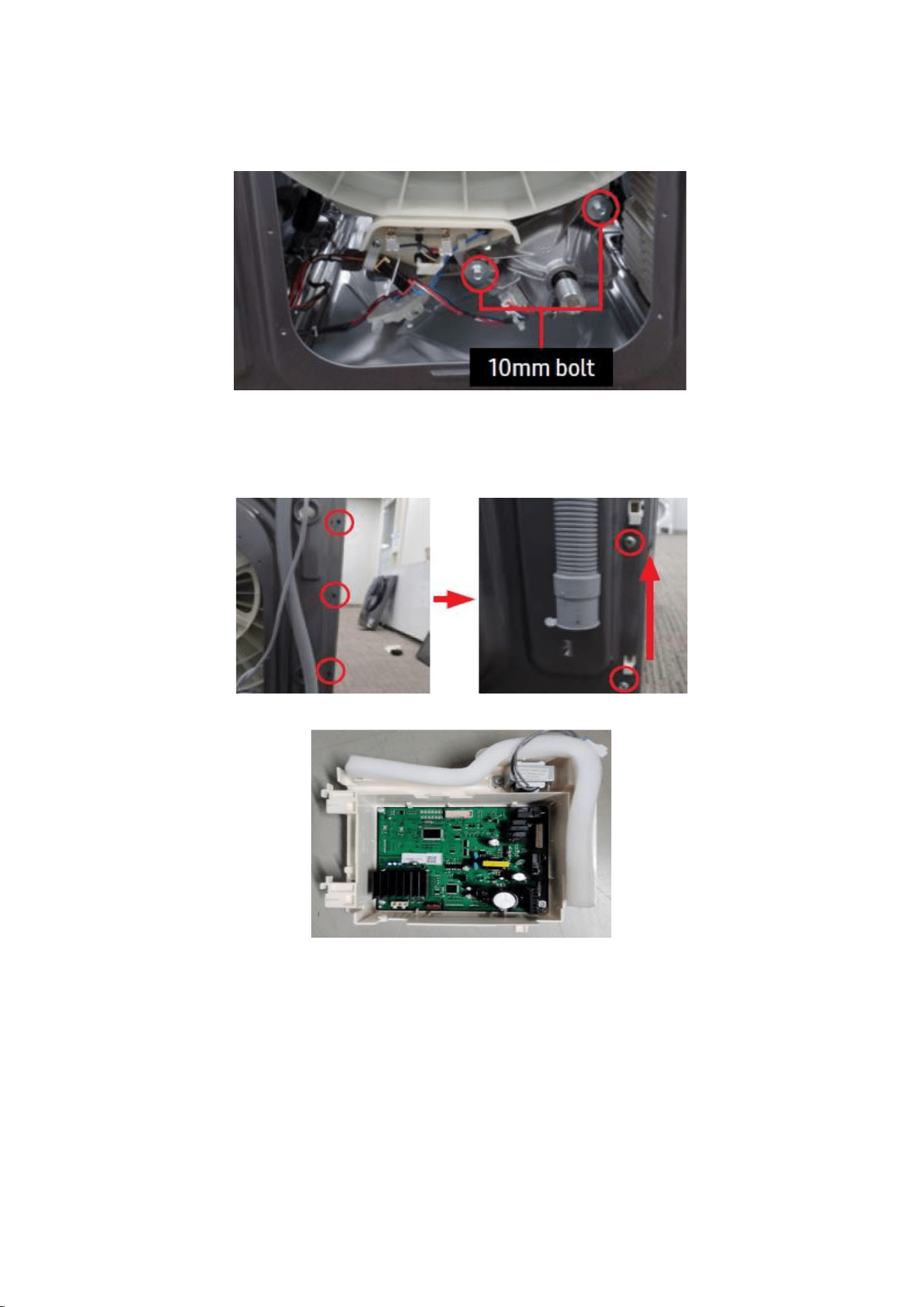
4. Remove the bolts (2ea) holding the motor at the back of the washing
machine using Box driver (10mm), Separate the motor by pulling it towards
you.
5. Remove guide wire by removing hooks using long nose plier
and remove 2 screws holding the Assy kit using (+) screw driver
on the right and pull it out from the set.
5-1. Separate Main PCB from the Frame.
39
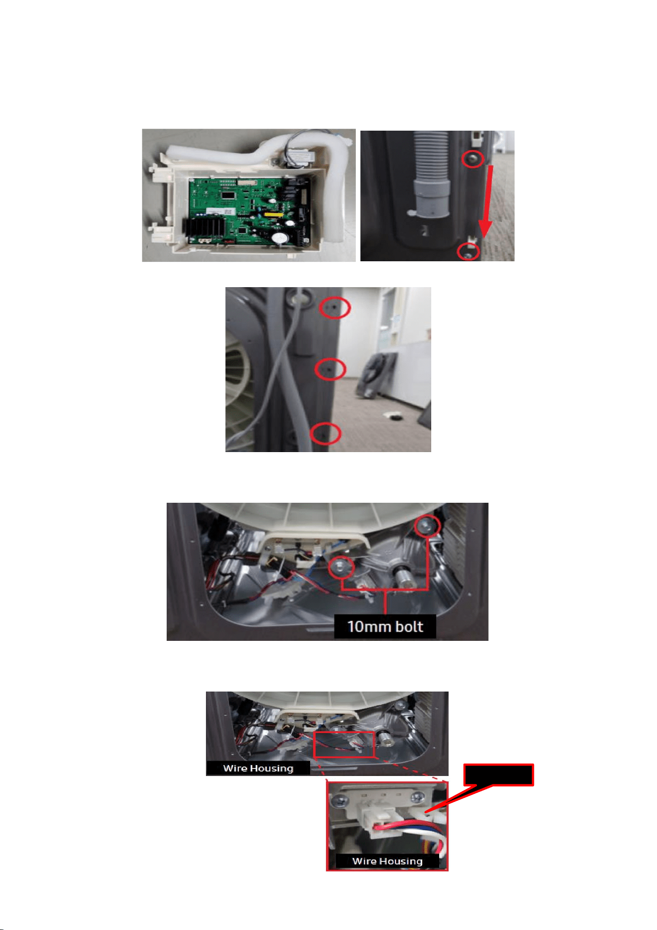
Reassembly
1. Connect Main PCB from the Frame, Aessemble 2 screws holding the
Assy kit using (+) screw driver on the right and pull it out from the set.
1-1. Remove guide wire by removing hooks using long nose plier
2. Conntect the motor and tub back, Assemble the bolts (2ea) holding
the motor at the back of the washing machine using Box driver (10mm).
3. Connect the Wire Housing and motor. Connect the Wire of red boxed place
from the guide wire
Guide wire
40
4. Separate the belt by pulling the belt towards your body
and slowly rotate the pulley.
4-1. When installing the Belt around the Motor Pulley, the bottom of the belt must
be located on the second tooth of the Motor Pulley.
5. Assemble 6 screws with (+) screw driver. Separate the Cover Back.

41
This guide is a property of Samsung Electronics Co.,Ltd.
Any unauthorized use of manual can be punished under applicable International
and/or domestic law.