EnglishDeutschFrançaisEspañolPortuguêsItalianoРусский
日本語
JA
RU
IT
PT
ES
FR
DE
EN
WALL-MOUNT CONTROLLER
MCP1
施工説明書
Installation Manual
Installationshandbuch
Manuel d’installation
Manual de instalación
Manual de instalação
Manuale all’installazione
Руководство по установке
Ver. 5.0 or later/Vers. 5.0 oder höher/Version 5.0 ou ultérieure/
Ver. 5.0 o posterior/Ver. 5.0 ou posterior/Ver. 5.0 o successiva/
Вер. 5.0 или более поздняя версия/Ver. 5.0
以降
To set up an MCP1 version 5.0 or later, use ProVisionaire Design.
To set up an MCP1 version earlier than 5.0, you can use only MTX-MRX Editor.
Ein MCP1 ab Version 5.0 mit ProVisionaire Design einrichten.
Ein MCP1 vor Version 5.0 kann nur mit MTX-MRX Editor eingerichtet werden.
Pour congurer un MCP1 doté de la version 5.0 ou d'une version ultérieure, utilisez le logiciel ProVisionaire Design.
Pour congurer un MCP1 doté d'une version antérieure à 5.0, seul le logiciel MTX-MRX Editor peut être utilisé.
Para congurar un MCP1 versión 5.0 o posterior, utilice ProVisionaire Design.
Para congurar un MCP1 de una versión anterior a la 5.0, solo se puede utilizar MTX-MRX Editor.
Para congurar um MCP1 versão 5.0 ou posterior, use o ProVisionaire Design.
Para congurar uma versão MCP1 anterior à 5.0, você pode usar apenas o MTX-MRX Editor.
Per impostare MCP1 in versione 5.0 o successiva, usare ProVisionarie Design.
Per impostare MCP1 in versione precedente alla 5.0, è possibile usare solo MTX-MRX Editor.
Для установки MCP1 версии 5.0 или более поздней версии используйте ProVisionaire Design.
Для установки MCP1 более ранней версии, чем 5.0, вы можете использовать только MTX-MRX Editor.
Ver5.0 以降の MCP1 は、ProVisionaireDesign で設定してください。
Ver.5.0 より前のバージョンは、MTX-MRXEditor でのみ設定できます。
2 MCP1 (Ver. 5.0 or later) Installation Manual
(can_b_02)
(class b korea)
This device complies with Part 15 of the FCC Rules. Operation is subject to the following two conditions:
(1) this device may not cause harmful interference, and (2) this device must accept any interference
received, including interference that may cause undesired operation.
CAN ICES-3 (B)/NMB-3(B)
이 기기는 가정용(B급) 전자파적합기기로서 주로 가정에서 사용하는 것을 목적으로 하며, 모든 지역에
서 사용할 수 있습니다.
1. IMPORTANT NOTICE: DO NOT MODIFY
THIS UNIT!
This product, when installed as indicated in
the instructions contained in this manual,
meets FCC requirements. Modifications not
expressly approved by Yamaha may void your
authority, granted by the FCC, to use the prod-
uct.
2. IMPORTANT: When connecting this product
to accessories and/or another product use
only high quality shielded cables. Cable/s sup-
plied with this product MUST be used. Follow
all installation instructions. Failure to follow
instructions could void your FCC authorization
to use this product in the USA.
3. NOTE: This product has been tested and
found to comply with the requirements listed in
FCC Regulations, Part 15 for Class “B” digital
devices. Compliance with these requirements
provides a reasonable level of assurance that
your use of this product in a residential envi-
ronment will not result in harmful interference
with other electronic devices. This equipment
generates/uses radio frequencies and, if not
installed and used according to the instruc-
tions found in the users manual, may cause
interference harmful to the operation of other
electronic devices. Compliance with FCC reg-
ulations does not guarantee that interference
will not occur in all installations. If this product
is found to be the source of interference, which
can be determined by turning the unit “OFF”
and “ON”, please try to eliminate the problem
by using one of the following measures:
Relocate either this product or the device that
is being affected by the interference.
Utilize power outlets that are on different
branch (circuit breaker or fuse) circuits or
install AC line filter/s.
In the case of radio or TV interference, relo-
cate/reorient the antenna. If the antenna lead-
in is 300 ohm ribbon lead, change the lead-in
to co-axial type cable.
If these corrective measures do not produce
satisfactory results, please contact the local
retailer authorized to distribute this type of
product. If you can not locate the appropriate
retailer, please contact Yamaha Corporation of
America, Electronic Service Division, 6600
Orangethorpe Ave, Buena Park, CA90620
The above statements apply ONLY to those
products distributed by Yamaha Corporation of
America or its subsidiaries.
(class B)
FCC INFORMATION (U.S.A.)
3MCP1 (Ver. 5.0 or later) Installation Manual
PRECAUTIONS
PLEASE READ CAREFULLY
BEFORE PROCEEDING
Please keep this manual in a safe
place for future reference.
WARNING
Always follow the basic precautions
listed below to avoid the possibility of
serious injury or even death from
electrical shock, short-circuiting,
damages, fire or other hazards. These
precautions include, but are not limited
to, the following:
Do not open
• This device contains no user-serviceable
parts. Do not open the device or attempt to
disassemble the internal parts or modify
them in any way. If it should appear to be
malfunctioning, discontinue use
immediately and have it inspected by
qualified Yamaha service personnel.
Water warning
• Do not expose the device to rain, use it
near water or in damp or wet conditions, or
place on it any containers (such as vases,
bottles or glasses) containing liquids which
might spill into any openings. If any liquid
such as water seeps into the device, turn
off the power of the PoE injector or the PoE
network switch immediately and unplug
the cable. Then have the device inspected
by qualified Yamaha service personnel.
• Never insert or remove a cable with wet
hands.
Fire warning
• Do not place any burning items or open
flames near the device, since they may
cause a fire.
If you notice any abnormality
• If any of the following problems occur,
immediately turn off the PoE injector or the
PoE network switch and disconnect the
cable.
- Unusual smells or smoke are emitted.
- Some object has been dropped into the
device.
- Cracks or other visible damage appear
on the device.
Then have the device inspected or
repaired by qualified Yamaha service
personnel.
CAUTION
Always follow the basic precautions
listed below to avoid the possibility of
physical injury to you or others, or
damage to the device or other property.
These precautions include, but are not
limited to, the following:
Location
• Do not place the device in a location where
it may come into contact with corrosive
gases or salt air. Doing so may result in
malfunction.
• Always consult qualified Yamaha service
personnel if the device installation requires
construction work, and make sure to
observe the following precautions.
- Choose mounting hardware and an
installation location that can support the
weight of the device.
- Avoid locations that are exposed to
constant vibration.
- Use the required tools to install the
device.
- Inspect the device periodically.
PA_en_8 1/2

4 MCP1 (Ver. 5.0 or later) Installation Manual
Handling caution
• Avoid inserting or dropping foreign objects
(paper, plastic, metal, etc.) into any gaps
or openings on the device (panel, etc.). If
this happens, immediately turn off the
power of the PoE injector or the PoE
network switch, unplug the cable, and
have the device inspected by qualified
Yamaha service personnel.
• Do not rest your weight on the device or
place heavy objects on it. Avoid applying
excessive force to the buttons, switches or
connectors to prevent injuries.
NOTICE
To avoid the possibility of malfunction/ damage to the product, damage to data, or damage to
other property, follow the notices below.
Handling and maintenance
• Do not use the device in the vicinity of a TV, radio, AV equipment, mobile phone, or other electric
devices. Otherwise, the device, TV, or radio may generate noise.
• Do not expose the device to excessive dust or vibration, or extreme cold or heat (such as in
direct sunlight, near a heater, or in a car during the day), in order to prevent the possibility of
panel disfiguration, unstable operation, or damage to the internal components.
• Do not place vinyl, plastic or rubber objects on the device, since this might discolor the panel.
• When cleaning the device, use a dry and soft cloth. Do not use paint thinners, solvents, cleaning
fluids, or chemical-impregnated wiping cloths.
• Condensation can occur in the device due to rapid, drastic changes in ambient tempera-
ture—when the device is moved from one location to another, or air conditioning is turned on or
off, for example. Using the device while condensation is present can cause damage. If there is
reason to believe that condensation might have occurred, leave the device for several hours
without turning on the power until the condensation has completely dried out.
• Be sure to operate the switch with bare hands. The switch will not work properly if operated with
gloved hands.
Information
About functions/data bundled with the device
• Use STP (Shielded Twisted Pair) cable to prevent electromagnetic interference.
About disposal
• This product contains recyclable components. When disposing of this product, please contact
the appropriate local authorities.
About this manual
• The illustrations and screens as shown in this manual are for instructional purposes only.
• The company names and product names in this manual are the trademarks or registered trade-
marks of their respective companies.
• Software may be revised and updated without prior notice.
Yamaha cannot be held responsible for
damage caused by improper use or
modifications to the device.
PA_en_8 2/2
5MCP1 (Ver. 5.0 or later) Installation Manual
Contents
PRECAUTIONS .....................................................................3
Introduction .......................................................................6
Controls and Connectors ........................................................7
Front Panel................................................................................................. 7
Rear Panel.................................................................................................. 8
Connecting the device...........................................................9
Function tree.................................................................... 10
Installation ...................................................................... 11
Setting the UNIT ID ............................................................. 13
Removal.......................................................................... 14
Initializing the MCP1 .......................................................... 14
Alert list.......................................................................... 15
Specifications .................................................................. 17
Dimensions ...................................................................... 18
Included items
• Mounting plate
• Surface mount box
• Side panel × 2
• Main unit — mounting plate screws × 4 (with washers)
• Mounting plate — surface mount box screws × 4 (without washers)
• MCP1 installation manual (this document)
Firmware update
ProVisionaire Design is used to update the firmware of the MCP1 and to check the ver-
sion. For details on how to perform these operations, refer to “ProVisionaire Design User
Guide.”
The latest firmware can be downloaded from the download page of the following website.
http://www.yamahaproaudio.com/

6 MCP1 (Ver. 5.0 or later) Installation Manual
Introduction
Thank you for purchasing a Yamaha MCP1 wall-mount controller. This product enables
you to control Yamaha devices as well as products manufactured by other companies
that have released compatible remote protocols. This installation manual explains how
to mount the unit when the installing technician or the designer installs or sets-up the
system. In order to take full advantage of this product’s many functions, be sure to read
this installation manual before installation.
After reading this manual, keep it for future reference.
The MCP1 lets you set up a home page and six pages, and assign up to 36 parameters.
What you’ll need to provide
When attaching the MCP1 to a wall, you’ll need to provide several items.
• PoE injector or PoE network switch that supports IEEE802.3af
This is used in order to supply power to the MCP1.
PoE injector units and PoE network switches are collectively referred to as “PSE (Power
Sourcing Equipment).”
• Ethernet cables (CAT5e or better)
These cables are used to connect to the PSE.
• (If embedding the unit in the wall)
2-gang box (without separator; 20 mm or greater depth)
You’ll also need screws for attaching the gang box to the wall.
• (If using a surface mount box)
Screws for attaching the surface mount box to the wall × 4
Provide M4.0 flat head screws of a length appropriate for the thickness of the wall.
• Phillips screwdriver / electric screwdriver
This is used for installation.
7MCP1 (Ver. 5.0 or later) Installation Manual
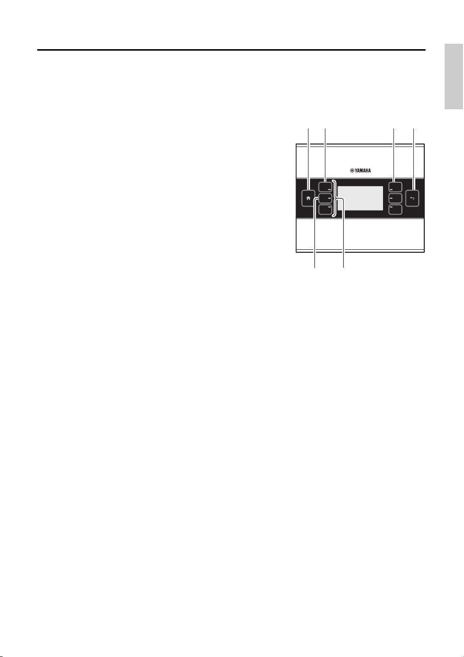
Controls and Connectors
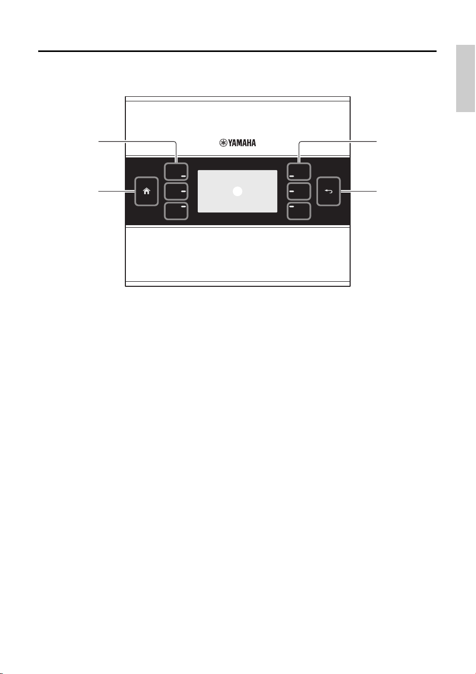
Front Panel
q Home switch
Touch this to return to the home page.
If you long-touch (more than two seconds) when the home page or another page is dis-
played, you’ll move to the utility page. If you long-press this while the display is locked or
sleeping, the lock or sleep state is defeated.
w L1/2/3 and R1/2/3 switches
Use these switches to move from the home page to another page, or to operate parameters.
Use ProVisionaire Design to specify the pages or parameters.
e Display
This shows parameters and other information. Use ProVisionaire Design to create the data
that will be shown.
r Return switch
After setting a parameter, touch this switch to confirm and return to the page or to move to a
confirmation screen.
r
e
w
q
w
Controls and Connectors
8 MCP1 (Ver. 5.0 or later) Installation Manual
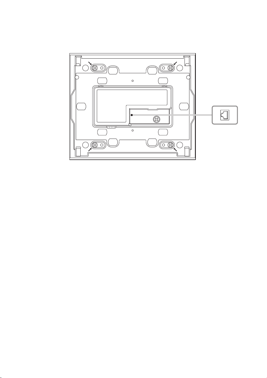
Rear Panel
t NETWORK port
This RJ-45 port is used to connect to the PSE.
The maximum cable length that can be used is 100 meters.
NOTE
Use STP (Shielded Twisted Pair) cable to prevent electromagnetic interference.
t
t
9MCP1 (Ver. 5.0 or later) Installation Manual
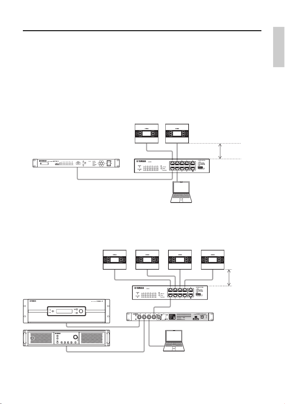
Connecting the device
Use an Ethernet cable to connect the MCP1, and the device that is controlled via the MCP1, to
a PoE network switch.
If the network switch does not support PoE, connect a PoE injector between the network
switch and the MCP1.
In some cases, the PSE (PoE network switch or PoE injector) might have ports that supply
power and ports that do not supply power. Connect the MCP1 to a port that supplies power.
For details on how to synchronize each device, refer to “ProVisionaire Design User Guide.”
Connections for a small system
Connections for a large system
Computer
MTX3
SWR2100P-10G
Maximum
100 meters
MCP1 MCP1
Computer
DME7
SWR2100P-10G
MCP1
Maximum
100 meters
PC412-DI
SWP1-16MMF
MCP1 MCP1 MCP1
10 MCP1 (Ver. 5.0 or later) Installation Manual
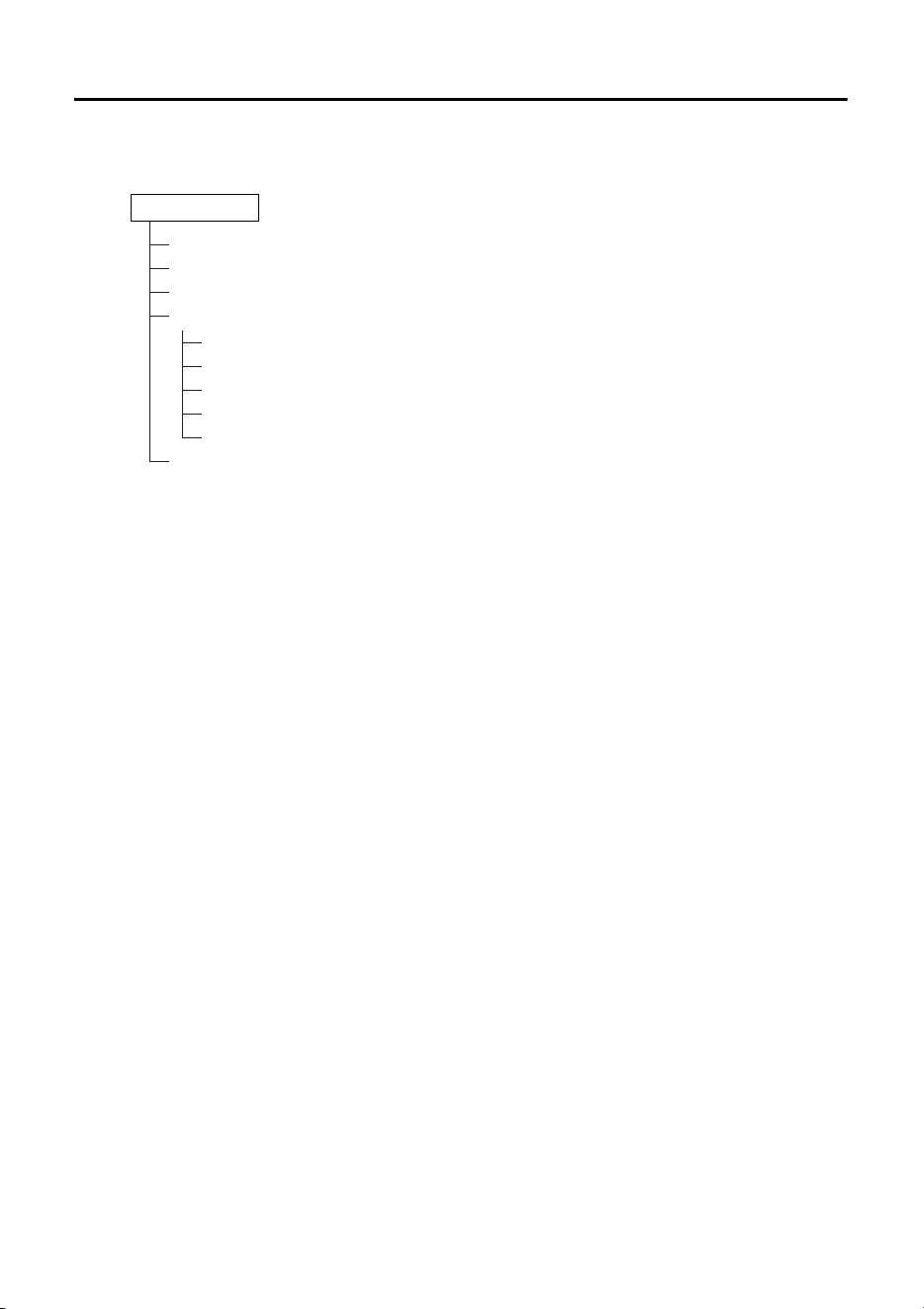
Function tree
If you long-touch (more than two seconds) the home switch when the home page or another page
is displayed, you’ll move to the utility page. The utility page contains the following function tree.
• LCD Brightness
Adjusts the brightness of the display backlight. Higher numbers increase the brightness.
• LCD Contrast
Adjusts the contrast of the display. Higher numbers increase the contrast.
• LED Brightness
Adjusts the brightness of the switches. Higher numbers increase the brightness.
•Settings
Moves to the settings page.
After synchronizing with ProVisionaire Design, it will be necessary to enter the PIN code. Use
ProVisionaire Design to set the PIN code.
• IP Setting
Selects either PC or UNIT ID as the method of specifying the MCP1’s IP address.
In the case of PC, use ProVisionaire Design to specify the IP address. In the case of UNIT ID,
the IP address will be 192.168.0.UNIT ID. After selecting PC or UNIT ID, touch the return
switch to move to the confirmation screen and automatically restart.
•Unit ID
Specifies the MCP1’s UNIT ID. The range of this setting is 01 through FE.
If IP Setting is UNIT ID, make settings so that there is no conflict with the IP address of
another device. After specifying UNIT ID, touch the return switch to move to the confirmation
screen and automatically restart.
• Initialize
Initializes the MCP1.
• Version
Display the firmware version of MCP1.
•Reboot
Restarts the MCP1.
•Alert
Display the alert number which has occurred current.
LCD Brightness
LCD Contrast
LED Brightness
Settings
IP Setting
Unit ID
Initialize
Version
Reboot
Alert
Utility page
11MCP1 (Ver. 5.0 or later) Installation Manual
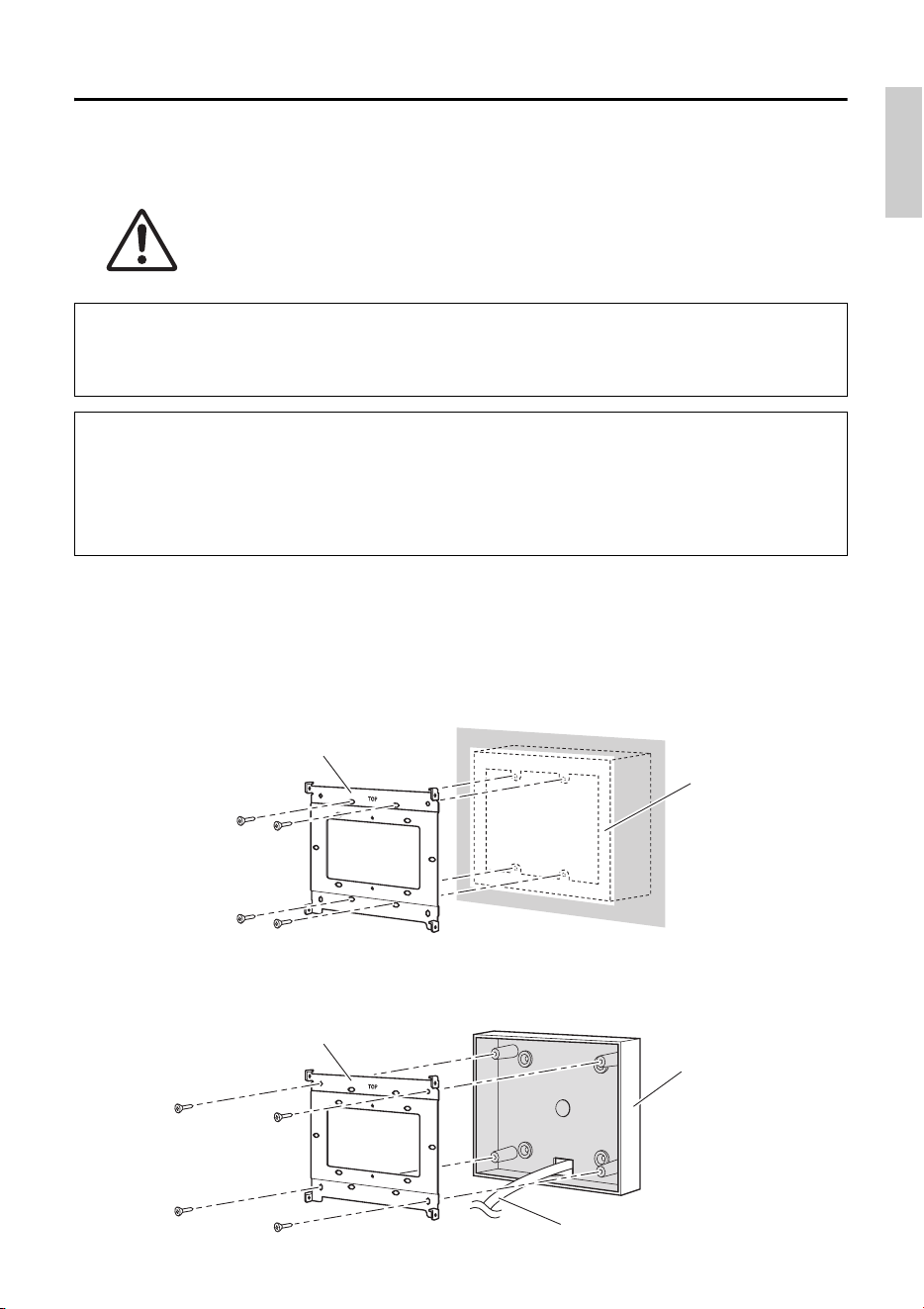
Installation
The MCP1 can be installed on a wall in either of two ways: in a gang box that is embedded
behind the wall, or in the included surface mount box which you attach to the surface of the
wall in an exposed position.
1. Attach the mounting plate to the gang box or the surface mount box.
Orient it so that the side printed “TOP” is toward yourself and above.
1- a.
If using a gang box
Align the elongated holes of the mounting place with the screw holes of the gang box,
and secure it in at least two locations.
1- b.
If using a surface mount box
Use the included screws without washers (M3.0 × 12).
CAUTION
Install the MCP1 no more than 2 meters above the floor. When MCP1 falls, it
becomes a cause by which MCP1 is damaged or you or others are injured.
If embedding the unit in a gang box installed behind the wall
Orient the gang box behind the wall in a horizontal position; into the gang box, pass the
cable that is connected to the PSE.
If installing the unit in the included surface mount box exposed on the surface of
the wall
The surface mount box has a cut-out that allows you to open a hole through which to pass the
cable. Open the hole in the cutout as necessary with a tool (such as a plier), pass the cable
into the surface mount box, and secure it using M4.0 flat head screws which you provide.
Mounting plate
Gang box
Mounting plate
Cable
Surface mount box
Installation
12 MCP1 (Ver. 5.0 or later) Installation Manual
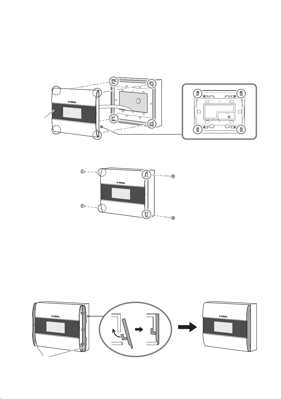
2. Connect the cable to the MCP1.
To the NETWORK port on the back of the MCP1, connect the cable that extends from the
PSE.
3. Fit the tabs of the mounting plate into the square holes of the MCP1.
4. While pressing the unit, use the included screws with washers to secure the unit in
four locations from the side.
5. Power-on the PSE.
6. Verify that the MCP1 starts.
If it starts, the PSE and the MCP1 are correctly connected.
7. Attach the side panels to the left and right sides of the MCP1.
Attach them so that they click into place.
Next, specify the UNIT ID.
NOTE
Do not attach the side panel yet. If there is a problem with connections, removing the side panel might
damage the side panel or the wall.
MCP1
Side panels
13MCP1 (Ver. 5.0 or later) Installation Manual
Setting the UNIT ID
Set the MCP1’s UNIT ID.
Operate the switches with bare hands. If you attempt to operate them while wearing gloves,
they will not work correctly.
1. Long-touch (two seconds or longer) the
home switch.
Move to the utility page.
2. Touch the [Settings] switch (R1).
Move to the settings page. After synchronizing
with ProVisionaire Design, it will be necessary to
enter the PIN code.
3. Touch the [IP Setting] switch (L1).
Specify whether the IP address is determined by
the UNIT ID or by ProVisionaire Design (PC).
4. Make sure that “IP Setting” is set to [UNIT
ID].
If it is set to [PC], touch the L1/2/3 switches at
the left to set it to [UNIT ID].
If you are using a subnet other than 192.168.0.x,
set this to [PC] and make the setting in
ProVisionaire Design.
5. Touch the return switch.
A confirmation screen appears; select Yes. The setting is confirmed as the UNIT ID, and
the MCP1 automatically restarts.
6. Touch the [Unit ID] switch (L2).
Set the MCP1’s UNIT ID.
Set the ID so that it does not conflict with the UNIT ID of another unit within the same net-
work.
Touching an L1/2/3 switch decreases the number; touching an R1/2/3 switch increases the
number.
7. When you’ve set the UNIT ID, touch the return switch.
A confirmation screen appears; select Yes. The UNIT ID is confirmed, and the MCP1 auto-
matically restarts.
NOTE
If you have forgotten the PIN code, use ProVisionaire
Design to specify it again.
3 2
6 5, 7
1 5, 7
14 MCP1 (Ver. 5.0 or later) Installation Manual
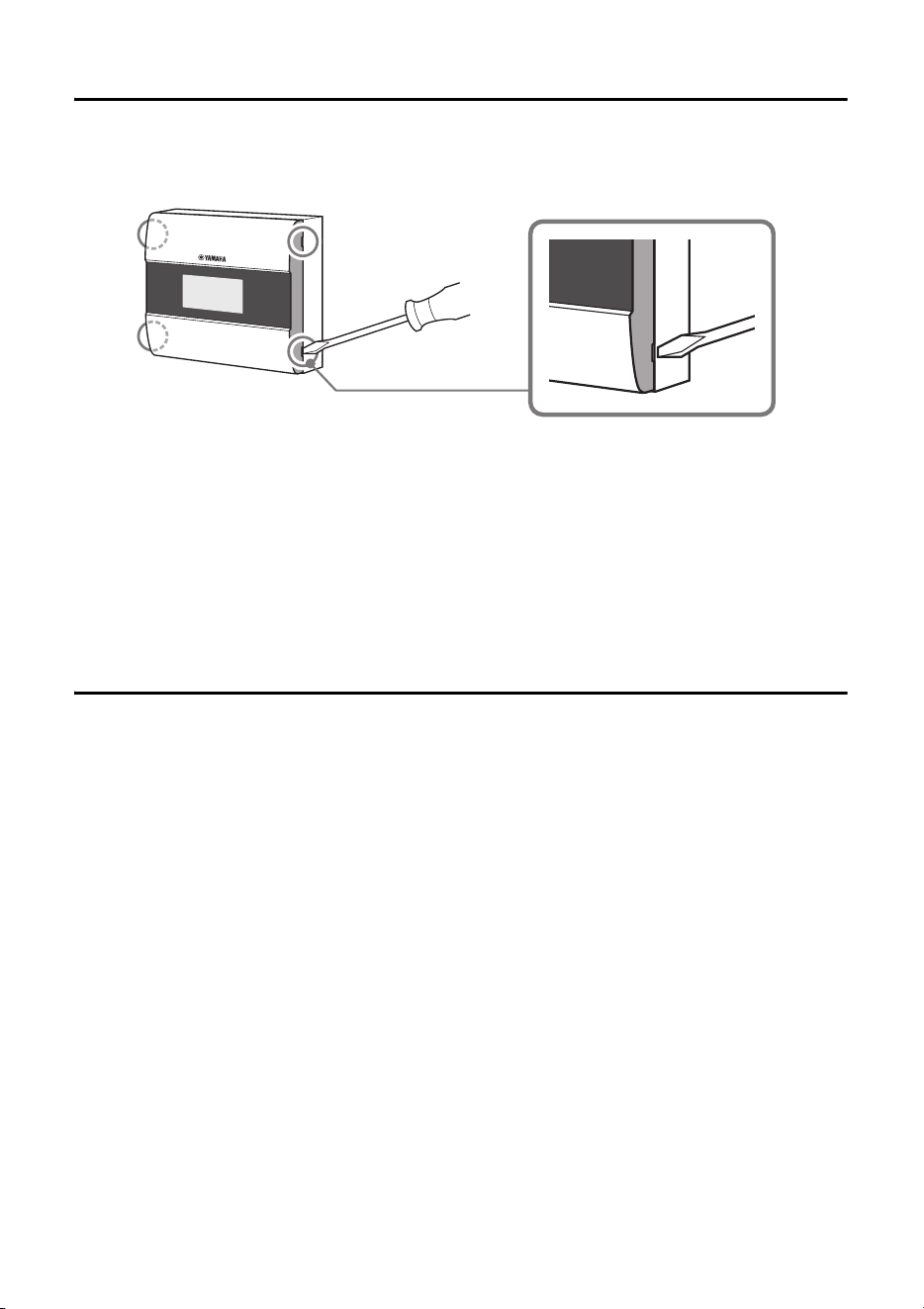
Removal
If you need to remove the MCP1, insert a slotted screwdriver into the notches of the side
panel, and twist. The subsequent steps are the reverse of the installation procedure.
Initializing the MCP1
With the unit powered on, perform the following procedure.
1. In the home page or another page, long-touch (two seconds or longer) the home
page switch.
Move to the utility page.
2. Touch the [Settings] switch (R1).
After synchronizing with ProVisionaire Design, it will be necessary to enter the PIN code.
3. Touch the [Initialize] switch (L3).
A confirmation screen appears; select Yes. Initialization begins, and the MCP1 automati-
cally restarts.
NOTE
When re-installing the MCP1, portions of the screw holes in the mount plate may be deformed and may not
properly fit into the MCP1. If this is the case, use a tool to adjust parts of the screw holes as necessary and
re-install the unit.
NOTE
If you have forgotten the PIN code, use ProVisionaire Design to specify it again.
15MCP1 (Ver. 5.0 or later) Installation Manual
Alert list
The following table lists the alerts generated by the MCP1, their meaning, and the appropriate
action to take.
When a Fault type alert occurs, it will immediately be displayed. Other alert types can be
checked by touching [Alert] in the Settings page. A single occurrence is shown when the situa-
tion occurs. A continuous occurrence is shown when the situation occurs and when it ends.
If the problem cannot be solved, contact your Yamaha dealer.
Number Content Action Type
Single /
Continuing
Device abnormality
001
The unit did not start up nor-
mally.
Turn off the power supply of the
PSE, wait at least six seconds,
and then turn on the power. If
this does not solve the problem,
initialize the MCP1.
Fault Continuing
003
Failed writing to internal flash
ROM.
Fault Continuing
005 MAC address was lost. Fault Continuing
017
Settings saved in internal
memory were lost.
Perform synchronization again
using ProVisionaire Design.
Fault Continuing
040 The IP address conflicts.
Make settings so that the IP
address does not conflict.
Error Continuing
041
The IP address was not estab-
lished within 60 seconds after
startup.
If the IP Setting is set to “PC,”
use ProVisionaire Design or the
DHCP server to specify the IP
address.
Warning Continuing
042
The device to be controlled
was not found on the network.
Power-on all devices making up
the system, and make sure that
they are correctly connected to
the network.
Error Continuing
043
Too many devices are con-
nected to the network.
Reduce the number of devices
connected to the network.
Error Single
051
A device with the same UNIT
ID was found among the
devices connected to the same
network.
Make settings so that the UNIT
ID does not conflict.
Error Continuing
060 Failed to recall a preset. Initialize the MCP1. Error Continuing
064
The preset could not be
recalled.
The Preset selected for recall
cannot be recalled as no data
has been stored to it, or another
device may have been added
after presets were stored.
Please synchronize and check
all presets using ProVisionaire
Design, and store again.
Warning Continuing
Alert list
16 MCP1 (Ver. 5.0 or later) Installation Manual
For other alerts, refer to “Alert list for MTX5-D/MTX3” in the “ProVisionaire Design User Guide.”
070
Synchronization has not been
completed. It may be that syn-
chronization was halted before
completion.
Perform synchronization again
using ProVisionaire Design. If
this does not solve the problem,
initialize the MCP1.
Error Continuing
071
The UNIT ID settings when
synchronization was per-
formed do not match the cur-
rent UNIT ID settings.
Do not change any UNIT ID’s
after performing synchroniza-
tion. If you’ve changed any
UNIT ID’s, perform synchroniza-
tion again.
Error Continuing
Number Content Action Type
Single /
Continuing
17MCP1 (Ver. 5.0 or later) Installation Manual
Specifications
European models
Purchaser/User Information specified in EN55103-2:2009.
Conforms to Environments: E1, E2, E3 and E4
The contents of this manual apply to the latest specifications as of the publishing date. To
obtain the latest manual, access the Yamaha website then download the manual file.
(rear_en_01)
Product specifications
Dimensions (W × H × D)
149(W) × 125(H) × 18(D) mm (when embedded in the wall)
152(W) × 128(H) × 46(D) mm (with a surface mount box)
Weight
0.6 kg (with a surface mount box)
0.5 kg (without a surface mount box)
Power supply voltage Power supplied via PoE (IEEE802.3af)
Power consumption 4.8 W max.
Operating temperature
range
0°C – 40°C
Storage temperature
range
-20°C – 60°C
Maximum number of units
usable simultaneously
Up to 16 MCP1 units can be installed per system
(There are limits on the total number of units within a system that includes
other devices)
Included items
Mounting plate, Surface mount box, Side panels (Two),
screws (2 kinds / Each 4 pcs.), Installation Manual
Separately sold option None
Connector specifications
Format NETWORK port: 10BASE-T/100BASE-TX
Cable specifications NETWORK port: CAT5e or better Ethernet STP cable
The model number, serial number, power requirements, etc., may be found on or near the
name plate, which is at the rear of the unit. You should note this serial number in the space
provided below and retain this manual as a permanent record of your purchase to aid
identification in the event of theft.
Model No.
Serial No.
18 MCP1 (Ver. 5.0 or later) Installation Manual
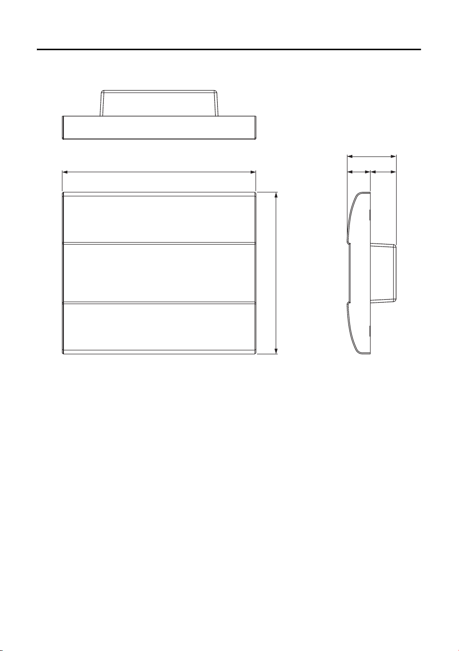
Dimensions
149
125
(20)(18)
38
Without surface mount box
Unit: mm
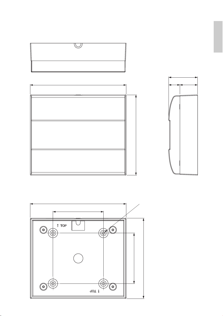
Dimensions
19MCP1 (Ver. 5.0 or later) Installation Manual
(28)(18)
46
152
128
128
80
4×
Ø
4.6
152
80
With surface mount box
Surface mount box
Unit: mm
20 MCP1 (Ver. 5.0 or later) Installation Manual
(weee_eu_en_02)
Information for users on collection and disposal of old equipment:
This symbol on the products, packaging, and/or accompanying documents
means that used electrical and electronic products should not be mixed with
general household waste.
For proper treatment, recovery and recycling of old products, please take
them to applicable collection points, in accordance with your national legisla-
tion.
By disposing of these products correctly, you will help to save valuable
resources and prevent any potential negative effects on human health and the
environment which could otherwise arise from inappropriate waste handling.
For more information about collection and recycling of old products, please
contact your local municipality, your waste disposal service or the point of sale
where you purchased the items.
For business users in the European Union:
If you wish to discard electrical and electronic equipment, please contact your
dealer or supplier for further information.
Information on Disposal in other Countries outside the European Union:
This symbol is only valid in the European Union. If you wish to discard these
items, please contact your local authorities or dealer and ask for the correct
method of disposal.

149MCP1 (Ver. 5.0 or later) Installation Manual
For detailed guarantee information about this Yamaha product, and Pan-EEA* and Switzerland warranty service, please either visit the website address below (Printable file is available
at our website) or contact the Yamaha representative office for your country. * EEA: European Economic Area
Important Notice: Guarantee Information for customers in EEA* and Switzerland
English
Für nähere Garantie-Information über dieses Produkt von Yamaha, sowie über den Pan-EWR*- und Schweizer Garantieservice, besuchen Sie bitte entweder die folgend angegebene Internetadresse
(eine druckfähige Version befindet sich auch auf unserer Webseite), oder wenden Sie sich an den für Ihr Land zuständigen Yamaha-Vertrieb. *EWR: Europäischer Wirtschaftsraum
Wichtiger Hinweis: Garantie-Information für Kunden in der EWR* und der Schweiz
Deutsch
Pour des informations plus détaillées sur la garantie de ce produit Yamaha et sur le service de garantie applicable dans l’ensemble de l’EEE ainsi qu’en Suisse, consultez notre site Web
à l’adresse ci-dessous (le fichier imprimable est disponible sur notre site Web) ou contactez directement Yamaha dans votre pays de résidence. * EEE : Espace Economique Européen
Remarque importante: informations de garantie pour les clients de l’EEE et la Suisse
Français
Voor gedetailleerde garantie-informatie over dit Yamaha-product en de garantieservice in heel de EER* en Zwitserland, gaat u naar de onderstaande website (u vind een afdrukbaar
bestand op onze website) of neemt u contact op met de vertegenwoordiging van Yamaha in uw land. * EER: Europese Economische Ruimte
Belangrijke mededeling: Garantie-informatie voor klanten in de EER* en Zwitserland
Nederlands
Para una información detallada sobre este producto Yamaha y sobre el soporte de garantía en la zona EEE* y Suiza, visite la dirección web que se incluye más abajo (la version del
archivo para imprimir esta disponible en nuestro sitio web) o póngase en contacto con el representante de Yamaha en su país. * EEE: Espacio Económico Europeo
Aviso importante: información sobre la garantía para los clientes del EEE* y Suiza
Español
Per informazioni dettagliate sulla garanzia relativa a questo prodotto Yamaha e l’assistenza in garanzia nei paesi EEA* e in Svizzera, potete consultare il sito Web all’indirizzo riportato
di seguito (è disponibile il file in formato stampabile) oppure contattare l’ufficio di rappresentanza locale della Yamaha. * EEA: Area Economica Europea
Avviso importante: informazioni sulla garanzia per i clienti residenti nell’EEA* e in Svizzera
Italiano
Para obter uma informação pormenorizada sobre este produto da Yamaha e sobre o serviço de garantia na AEE* e na Suíça, visite o site a seguir (o arquivo para impressão está
disponível no nosso site) ou entre em contato com o escritório de representação da Yamaha no seu país. * AEE: Área Econômica Européia
Aviso importante: informações sobre as garantias para clientes da AEE* e da Suíça
Português
Για λεπτομερείς πληροφορίες εγγύησης σχετικά με το παρόν προϊόν της Yamaha και την κάλυψη εγγύησης σε όλες τις χώρες του ΕΟΧ και την Ελβετία, επισκεφτείτε την παρακάτω
ιστοσελίδα (Εκτυπώσιμη μορφή είναι διαθέσιμη στην ιστοσελίδα μας) ή απευθυνθείτε στην αντιπροσωπεία της Yamaha στη χώρα σας. * ΕΟΧ: Ευρωπαϊκός Οικονομικός Χώρος
Σημαντική σημείωση: Πληροφορίες εγγύησης για τους πελάτες στον ΕΟΧ* και Ελβετία
Ελληνικά
För detaljerad information om denna Yamahaprodukt samt garantiservice i hela EES-området* och Schweiz kan du antingen besöka nedanstående webbaddress (en utskriftsvänlig fil
finns på webbplatsen) eller kontakta Yamahas officiella representant i ditt land. * EES: Europeiska Ekonomiska Samarbetsområdet
Viktigt: Garantiinformation för kunder i EES-området* och Schweiz
Svenska
Detaljert garantiinformasjon om dette Yamaha-produktet og garantiservice for hele EØS-området* og Sveits kan fås enten ved å besøke nettadressen nedenfor (utskriftsversjon finnes
på våre nettsider) eller kontakte kontakte Yamaha-kontoret i landet der du bor. *EØS: Det europeiske økonomiske samarbeidsområdet
Viktig merknad: Garantiinformasjon for kunder i EØS* og Sveits
Norsk
De kan finde detaljerede garantioplysninger om dette Yamaha-produkt og den fælles garantiserviceordning for EØO* (og Schweiz) ved at besøge det websted, der er angivet nedenfor (der
findes en fil, som kan udskrives, på vores websted), eller ved at kontakte Yamahas nationale repræsentationskontor i det land, hvor De bor. * EØO: Det Europæiske Økonomiske Område
Vigtig oplysning: Garantioplysninger til kunder i EØO* og Schweiz
Dansk
Tämän Yamaha-tuotteen sekä ETA-alueen ja Sveitsin takuuta koskevat yksityiskohtaiset tiedot saatte alla olevasta nettiosoitteesta. (Tulostettava tiedosto saatavissa sivustollamme.)
Voitte myös ottaa yhteyttä paikalliseen Yamaha-edustajaan. *ETA: Euroopan talousalue
Tärkeä ilmoitus: Takuutiedot Euroopan talousalueen (ETA)* ja Sveitsin asiakkaille
Suomi
Aby dowiedzieć się więcej na temat warunków gwarancyjnych tego produktu firmy Yamaha i serwisu gwarancyjnego w całym EOG* i Szwajcarii, należy odwiedzić wskazaną poniżej stronę internetową
(Plik gotowy do wydruku znajduje się na naszej stronie internetowej) lub skontaktować się z przedstawicielstwem firmy Yamaha w swoim kraju. * EOG — Europejski Obszar Gospodarczy
Ważne: Warunki gwarancyjne obowiązujące w EOG* i Szwajcarii
Polski
Podrobné záruční informace o tomto produktu Yamaha a záručním servisu v celém EHS* a ve Švýcarsku naleznete na níže uvedené webové adrese (soubor k tisku je dostupný na našich
webových stránkách) nebo se můžete obrátit na zastoupení firmy Yamaha ve své zemi. * EHS: Evropský hospodářský prostor
Důležité oznámení: Záruční informace pro zákazníky v EHS* a ve Švýcarsku
Česky
A jelen Yamaha termékre vonatkozó részletes garancia-információk, valamint az EGT*-re és Svájcra kiterjedő garanciális szolgáltatás tekintetében keresse fel webhelyünket az alábbi
címen (a webhelyen nyomtatható fájlt is talál), vagy pedig lépjen kapcsolatba az országában működő Yamaha képviseleti irodával. * EGT: Európai Gazdasági Térség
Fontos figyelmeztetés: Garancia-információk az EGT* területén és Svájcban élő vásárlók számára
Magyar
Täpsema teabe saamiseks selle Yamaha toote garantii ning kogu Euroopa Majanduspiirkonna ja Šveitsi garantiiteeninduse kohta, külastage palun veebisaiti alljärgneval aadressil (meie
saidil on saadaval prinditav fail) või pöörduge Teie regiooni Yamaha esinduse poole. * EMP: Euroopa Majanduspiirkond
Oluline märkus: Garantiiteave Euroopa Majanduspiirkonna (EMP)* ja Šveitsi klientidele
Eesti keel
Lai saņemtu detalizētu garantijas informāciju par šo Yamaha produktu, kā arī garantijas apkalpošanu EEZ* un Šveicē, lūdzu, apmeklējiet zemāk norādīto tīmekļa vietnes adresi (tīmekļa
vietnē ir pieejams drukājams fails) vai sazinieties ar jūsu valsti apkalpojošo Yamaha pārstāvniecību. * EEZ: Eiropas Ekonomikas zona
Svarīgs paziņojums: garantijas informācija klientiem EEZ* un Šveicē
Latviešu
Jei reikia išsamios informacijos apie šį „Yamaha“ produktą ir jo techninę priežiūrą visoje EEE* ir Šveicarijoje, apsilankykite mūsų svetainėje toliau nurodytu adresu (svetainėje yra
spausdintinas failas) arba kreipkitės į „Yamaha“ atstovybę savo šaliai. *EEE – Europos ekonominė erdvė
Dėmesio: informacija dėl garantijos pirkėjams EEE* ir Šveicarijoje
Lietuvių kalba
Podrobné informácie o záruke týkajúce sa tohto produktu od spoločnosti Yamaha a garančnom servise v EHP* a Švajčiarsku nájdete na webovej stránke uvedenej nižšie (na našej
webovej stránke je k dispozícii súbor na tlač) alebo sa obráťte na zástupcu spoločnosti Yamaha vo svojej krajine. * EHP: Európsky hospodársky priestor
Dôležité upozornenie: Informácie o záruke pre zákazníkov v EHP* a Švajčiarsku
Slovenčina
Za podrobnejše informacije o tem Yamahinem izdelku ter garancijskem servisu v celotnem EGP in Švici, obiščite spletno mesto, ki je navedeno spodaj (natisljiva datoteka je na voljo na
našem spletnem mestu), ali se obrnite na Yamahinega predstavnika v svoji državi. * EGP: Evropski gospodarski prostor
Pomembno obvestilo: Informacije o garanciji za kupce v EGP* in Švici
Slovenščina
За подробна информация за гаранцията за този продукт на Yamaha и гаранционното обслужване в паневропейската зона на ЕИП* и Швейцария или посетете посочения по-долу уеб
сайт (на нашия уеб сайт има файл за печат), или се свържете с представителния офис на Yamaha във вашата страна. * ЕИП: Европейско икономическо пространство
Важно съобщение: Информация за гаранцията за клиенти в ЕИП* и Швейцария
Български език
Pentru informaţii detaliate privind acest produs Yamaha şi serviciul de garanţie Pan-SEE* şi Elveţia, vizitaţi site-ul la adresa de mai jos (fişierul imprimabil este disponibil pe site-ul nostru)
sau contactaţi biroul reprezentanţei Yamaha din ţara dumneavoastră. * SEE: Spaţiul Economic European
Notificare importantă: Informaţii despre garanţie pentru clienţii din SEE* şi Elveţia
Limba română
Za detaljne informacije o jamstvu za ovaj Yamahin proizvod te jamstvenom servisu za cijeli EGP i Švicarsku, molimo Vas da posjetite web-stranicu navedenu u nastavku ili kontaktirate
ovlaštenog Yamahinog dobavljača u svojoj zemlji. * EGP: Europski gospodarski prostor
Važna obavijest: Informacije o jamstvu za države EGP-a i Švicarske
Hrvatski
https://europe.yamaha.com/warranty/
URL_5
Important Notice: Guarantee Information for customers in European
Economic Area (EEA) and Switzerland
150 MCP1 (Ver. 5.0 or later) Installation Manual
Yamaha Worldwide Representative Offices
For details on the product(s), contact your nearest Yamaha representative or the authorized distribu-
tor, found by accessing the 2D barcode below.
English
Wenden Sie sich für nähere Informationen zu Produkten an eine Yamaha-Vertretung oder einen
autorisierten Händler in Ihrer Nähe. Diese finden Sie mithilfe des unten abgebildeten 2D-Strichodes.
Deutsch
Pour obtenir des informations sur le ou les produits, contactez votre représentant ou revendeur agréé
Yamaha le plus proche. Vous le trouverez à l'aide du code-barres 2D ci-dessous.
Français
Para ver información detallada sobre el producto, contacte con su representante o distribuidor
autorizado Yamaha más cercano. Lo encontrará escaneando el siguiente código de barras 2D.
Español
Per dettagli sui prodotti, contattare il rappresentante Yamaha o il distributore autorizzato più vicino,
che è possibile trovare tramite il codice a barre 2D in basso.
Italiano
Para mais informações sobre o(s) produto(s), fale com seu representante da Yamaha mais próximo
ou com o distribuidor autorizado acessando o código de barras 2D abaixo.
Português
ɑɬɨɛɵɭɡɧɚɬɶɩɨɞɪɨɛɧɟɟɨɩɪɨɞɭɤɬɟɩɪɨɞɭɤɬɚɯɫɜɹɠɢɬɟɫɶɫɛɥɢɠɚɣɲɢɦɩɪɟɞɫɬɚɜɢɬɟɥɟɦɢɥɢ
ɚɜɬɨɪɢɡɨɜɚɧɧɵɦɞɢɫɬɪɢɛɶɸɬɨɪɨɦ<DPDKDɜɨɫɩɨɥɶɡɨɜɚɜɲɢɫɶɞɜɭɯɦɟɪɧɵɦɲɬɪɢɯɤɨɞɨɦɧɢɠɟ
Ɋɭɫɫɤɢɣ
㥵剣Ⱒ❡ㅷ涸霫絈⥌䜂霼翫禹騄䝠剒鵛涸:BNBIB➿邍䧴䱇勉絑Ꝉ㉁〳鸑鵂霄♴倰
涸%勵䕎瀦䪪ⵌ鵯❈➿邍䧴絑Ꝉ㉁涸⥌䜂կ
皍⡤⚥俒
㞞ꧏ榣⿁氳鎌碸鞴銻鑃绤礙艃䖼ꦗ鲥氳:BNBIBꊸす♏辑䡝䪧垷祺ꊸり䖼⺎♓䬟┖亡氳◅禵
半澰刨洇注绤礙鞴乣
竵냉╈乄
헪펞샎핞켆헣쫂쁢팒앦%짢슪펞펟켆큲펺많밚풂:BNBIB샂샇잲헞쏞쁢뫃킫샎읺헞펞
줆픦킻킪폲
묻펂
https://manual.yamaha.com/pa/address_list/
Head Oce/Manufacturer: Yamaha Corporation 10-1, Nakazawa-cho, Chuo-ku, Hamamatsu, 430-8650, Japan
Importer (European Union): Yamaha Music Europe GmbH Siemensstrasse 22-34, 25462 Rellingen, Germany
Importer (United Kingdom): Yamaha Music Europe GmbH (UK) Sherbourne Drive, Tilbrook, Milton Keynes, MK7 8BL, United Kingdom
PA61


© 2017 Yamaha Corporation
Published 01/2024
IPES-D0
Yamaha Pro Audio global website
https://www.yamahaproaudio.com/
Yamaha Downloads
https://download.yamaha.com/
VGY0250