Service Manual
Before troubleshooting or servicing equipment, review equipment
installation guides and conrm ALL installation requirements
& specications have been met. Including, but not limited to:
wiring, clearance, ducting (where applicable), power, and line set
requirements. Correct any installation issues before continuing.
Appearances vary by model
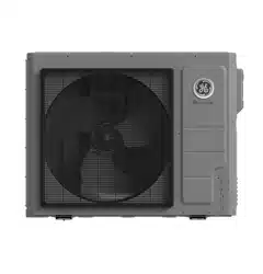
Outdoor Models
Appearances vary by model
Indoor Models
1G24ED2BEA
1G3036ED2BEA
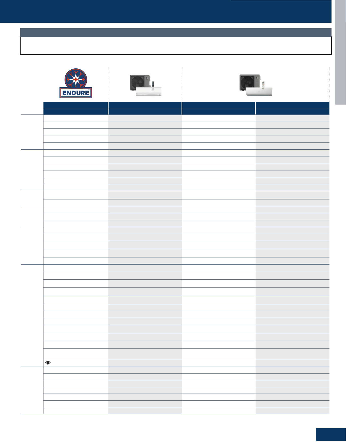
Wall Mount - Highwall
GS24WP2BEA
GS30WB2BEA
GS36WB2BEA
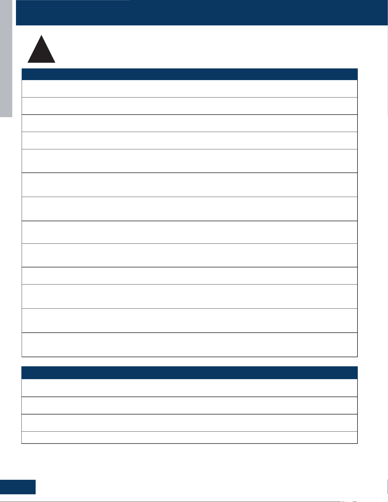
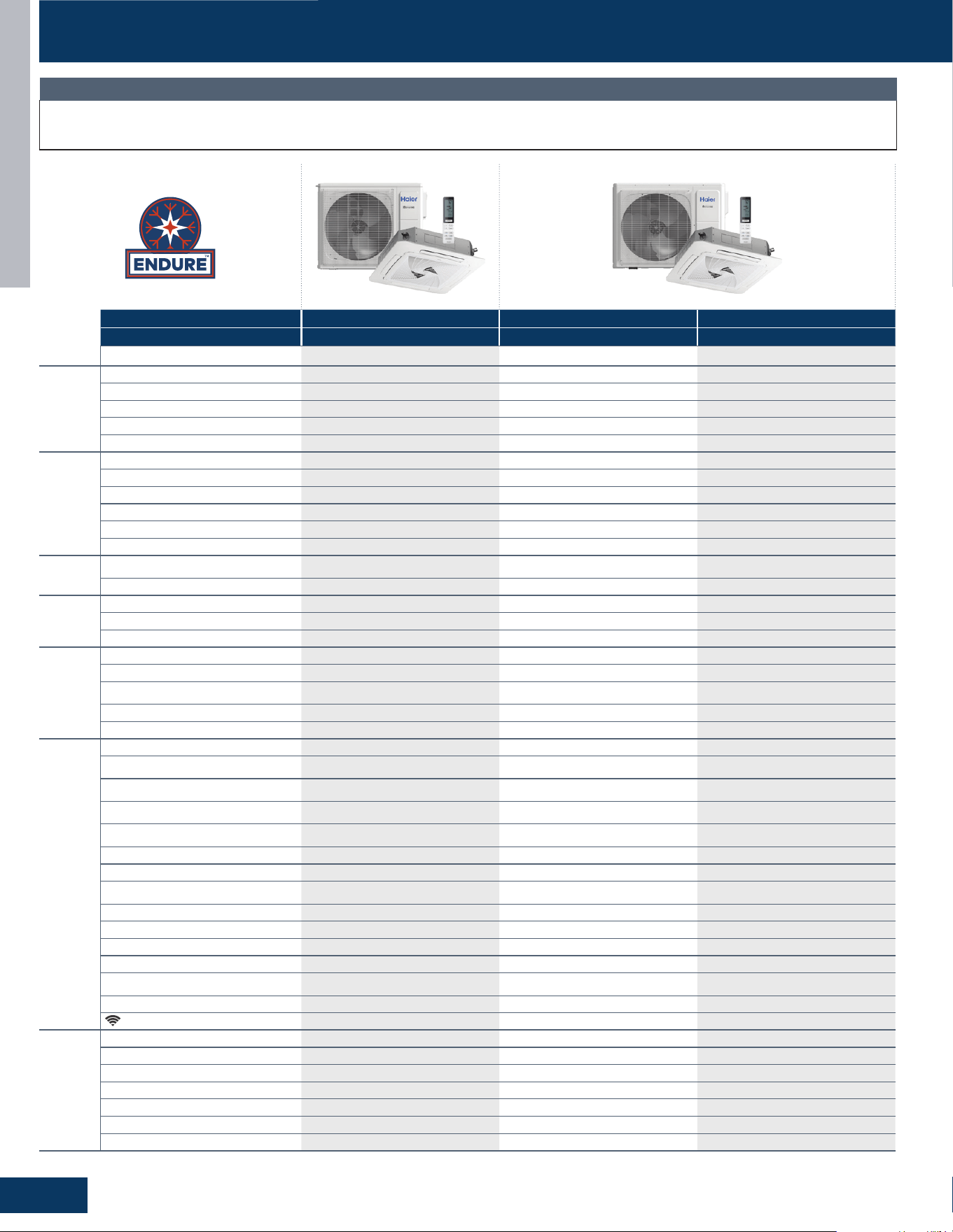
Cassette
US24LB2BEA
US30LB2BEA
US36LB2BEA
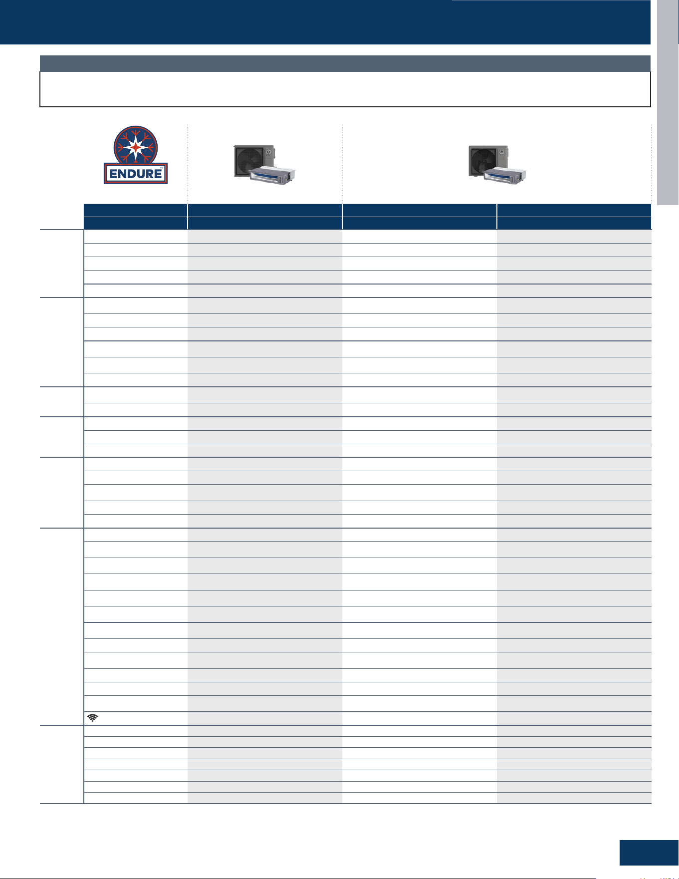
Mid-Static Ducted
US24MB2BEA
US30MB2BEA
US36MB2BEA
Model Lineup:
Single-Zone
Ductless Multi-Split Heat Pumps

INTRODUCTION
2
ENGLISH
TABLE OF CONTENTS
Introduction ................................................................................................................. A1
Outdoor Units
...............................................................................................................B1
Highwalls
..................................................................................................................... C1
Cassettes
..................................................................................................................... D1
Mid-Static Ducted
.........................................................................................................E1
Troubleshooting And Reference
....................................................................................F1
10-16-25: Edition release.

INTRODUCTION
A1
ENGLISH
INTRODUCTION
TABLE OF CONTENTS
SAFETY & PRECAUTIONS .......................................................................................................................................................A2
SPECIFICATIONS
....................................................................................................................................................................A3
Highwall Indoor ......................................................................................................................................................................A3
Cassette Indoor .....................................................................................................................................................................A4
Ducted Indoor ........................................................................................................................................................................A5
OPERATING FUNCTIONS AND CONTROLS ............................................................................................................................A6
Cooling Mode ..........................................................................................................................................................................A6
Heating Mode .........................................................................................................................................................................A7
Defrost Operation ..................................................................................................................................................................A8
Dry Mode .................................................................................................................................................................................A9
Auto Restart ............................................................................................................................................................................ A9
Compressor and Outdoor Fan ...............................................................................................................................................A9
Outdoor Unit Electronic Expansion Valve (EEV) .................................................................................................................A10
Four-Way Valve Control ........................................................................................................................................................A10
Base Pan Heater ....................................................................................................................................................................A11
Compressor Heater Band ....................................................................................................................................................A11
Capacity Loss Per Piping Length .........................................................................................................................................A11
SPECIAL FUNCTIONS AND CONTROLS ................................................................................................................................ A12
Cold Air Prevention ...............................................................................................................................................................A12
ECO Function ........................................................................................................................................................................A12
Forced Heating/Cooling .......................................................................................................................................................A12
Temperature Compensation ...............................................................................................................................................A13
PROTECTION FUNCTIONS AND CONTROLS ........................................................................................................................A14
Protection Controls ..............................................................................................................................................................A14
Compressor Discharge Protection ......................................................................................................................................A15
Compressor/High Current Protection ................................................................................................................................A15
Low Pressure Protection ......................................................................................................................................................A16
High Pressure Protection .....................................................................................................................................................A16
Indoor Antifreeze Protection ...............................................................................................................................................A16
Indoor Coil Thermal Overload Protection in Heating Mode ...............................................................................................A16
Oil Return Cycle ....................................................................................................................................................................A17
INTRODUCTION
A2
ENGLISH
SAFETY & PRECAUTIONS
FOLLOW ALL WARNINGS, CAUTIONS, AND PRECAUTIONS BELOW, AND INDUSTRY BEST
SAFETY PRACTICES AND STANDARDS. FAILURE TO DO SO MAY RESULT IN EQUIPMENT
DAMAGE OR FAILURE, AND SERIOUS PERSONAL INJURY OR DEATH.
!
WARNINGS
Service should be performed by the dealer or another professional.
Improper service may cause water leakage, electrical shock, or re.
Use only the supplied or specied service parts.
Use of other parts may cause the unit to come lose, water leakage, electrical shock, or re.
The heat pump must be installed on a solid base that can support the unit’s weight.
An inadequate base or incomplete installation may cause injury in the event the unit falls o the base.
Electrical work should be carried out in accordance with the manual and national/local electrical wiring codes and rules of practice.
Insucient capacity or incomplete electrical work may cause electrical shock or re.
A dedicated power circuit must be used. The power supply should NEVER be shared by another appliance.
Wiring cable must be long enough to cover the entire distance with no splices.
Do not use an extension cord. Do not put other loads on the power supply, use a dedicated power circuit.
Failure to do so may cause abnormal heat, electric shock or re.
Only the specied wire types may be used for electrical connections between the indoor and outdoor units.
Firmly clamp the interconnecting wires so they receive no external stresses. Incomplete connections or clamping may cause terminal
overheating or re.
Wiring must not put undue stress or tension on the electrical covers or panels.
Install covers over the wires. Incomplete cover installation may cause terminal overheating, electrical shock, or re.
If any refrigerant has leaked out during service work, ventilate the room.
The refrigerant produces a toxic gas if exposed to ame.
After all service is complete, check for and repair any system refrigerant leaks.
The refrigerant produces a toxic gas if exposed to ames.
When servicing or relocating the system, keep the refrigerant circuit free from substances other than the specied refrigerant
(R454B), such as air or moisture
The presence of air or other foreign substance in the refrigerant circuit causes an abnormal pressure rise or rupture, resulting in injury.
During pump-down, stop the compressor before removing the refrigerant piping.
If the compressor is still running, and the stop valve is open during pump-down, air will be sucked into the system while the compressor
is running. This will cause abnormal pressure and noncondensables added to the system.
Unit must NOT be grounded to a utility pipe, arrester, or telephone line ground.
An complete ground may cause electrical shock, or re. A high surge current from lightning or other sources may cause damage to the
heat pump.
CAUTIONS
The heat pump must not be installed in a place where there is danger of exposure to ammable gas.
If the gas builds up around the unit, it may catch re.
Drain piping must comply with installation guidelines.
Inadequate piping may cause ooding.
Tighten are nuts according to the specied torque using a torque wrench.
If are nuts are overtightened, they may eventually crack and cause refrigerant leakage.
Ensure proper clearances around unit per installation guidelines.
INTRODUCTION
A3
ENGLISH
Outdoor Unit 1G24ED2BEA 1G3036ED2BEA 1G3036ED2BEA
Indoor Unit GS24WP2BEA GS30WB2BEA GS36WB2BEA
Cooling
Rated Capacity Btu/hr 24,000 30,000 32,400
Capacity Range Btu/hr 4,500-26,000 6,000-31,000 6,000-33,500
SEER2 20 20 20
EER2 11.2 11.2 10.5
Moisture Removal Pt./hr 6 7.5 7.9
Heating
Rated Heating Capacity 47°F Btu/hr 24,000 31,000 37,000
Heating Capacity Range Btu/hr 4,000-26,000 6,500-32,500 6,500-37,000
HSPF2 (IV) 9.5 9.5 9.5
Rated Heating Capacity 5°F Btu/hr 22,000 25,800 26,200
Heating Capacity at 5°F / Capacity at 47°F 92% 83% 71%
COP 5°F 1.8 1.8 1.8
Operating
Range
Cooling
(Without Wind Bae or Top Cover)
23~115°F (-5~46°C) 23~115°F (-5~46°C) 23~115°F (-5~46°C)
Heating -22~75°F (-30~24°C) -22~75°F (-30~24°C) -22~75°F (-30~24°C)
Power Supply
Voltage, Cycle, Phase (V/Hz/-) 208-230/60/1 208-230/60/1 208-230/60/1
Maximum Fuse Size A 30 40 40
Minimum Circuit Amp A 22 25 25
Outdoor Unit
Compressor Type DC Inverter Rotary DC Inverter Rotary DC Inverter Rotary
Outdoor Noise Level dB 64 72 73
Dimension: H x W x D in (mm)
30 1/8 x 40 3/16 x 17 1/8
(765 x 1021 x 435)
33 1/16 x 43 1/8 x 19 7/8
(840 x 1095 x 505)
33 1/16 x 43 1/8 x 19 7/8
(840 x 1095 x 505)
Weight (Net/Ship) - lbs (kg) 134.7/173.06 (61.1/78.5)
165.42/211.64
(75/96)
165.42/211.64
(75/96)
Basepan Heater Yes Yes Yes
Indoor Unit
Fan Speed Stages 5 + Auto 5 + Auto 5 + Auto
Airow CFM: Cooling
(Turbo/High/Med/Low/Quiet)
800/730/630/535/440 800/725/650/510/430 840/765/690/550/470
Airow CFM: Heating
(Turbo/High/Med/Low/Quiet)
800/730/630/535/440 800/725/650/510/430 840/765/690/550/470
Indoor Sound Level dB: Cooling
(Turbo/High/Med/Low/Quiet)
54/50/47/44/38 55/53/49/44/40 56/54/50/44/40
Indoor Sound Level dB: Heating
(Turbo/High/Med/Low/Quiet)
54/50/47/44/38 55/53/49/44/40 56/54/50/44/40
Auto Up-Down Louver Ye s Ye s
Yes
Auto Left-Right Louver Ye s No No
Drain Pipe Size O.D in 5/8 5/8 5/8
Dimension: H x W x D in (mm)
13 1/2 x 44 1/2 x 9 1/8
(343 x 1129 x 232)
14 3/8 x 52 3/4 x 10 3/4
(365 x 1341 x 274)
14 3/8 x 52 3/4 x 10 3/4
(365 x 1341 x 274)
Weight (Net/Ship) - lbs (kg) 34.86/43.03 (15.8/19.5) 46.34/56.27 (21/25.5) 46.34/56.27 (21/25.5)
Factory-Installed Refrigerant Detection
Sensor (RDS)
No No No
Refrigerant Detection Sensor (RDS)
Compatible
Yes
(UALS01A,
sold seperately)
Yes
(UALS01A,
sold seperately)
Yes
(UALS01A,
sold seperately)
WiFi*
Built-in Built-in Built-in
Refrigerant
Lines
Refrigerant R454B R454B R454B
Connections Flare Flare Flare
Liquid O.D. in 1/4 3/8 3/8
Suction O.D. in 1/2 5/8 5/8
Factory Charge Oz 77.7 109.4 109.4
Maximum Line Length Ft / m 165/50 165/50 165/50
Maximum Height Ft / m 100/30 100/30 100/30
SPECIFICATIONS
Our continued commitment to quality products may mean a change in specications without notice.
Visit GEAppliancesAirandWater.com to access current specication tables online.
NOTE
*WiFi includes SmartHQ
TM
Home and SmartHQ
TM
Service compatibility.
INTRODUCTION
A4
ENGLISH
Our continued commitment to quality products may mean a change in specications without notice.
Visit GEAppliancesAirandWater.com to access current specication tables online.
NOTE
Outdoor Unit 1G24ED2BEA 1G3036ED2BEA 1G3036ED2BEA
Indoor Unit US24LB2BEA US30LB2BEA US36LB2BEA
Panel (required, sold separately) GALCP01GA GALCP01GA GALCP01GA
Cooling
Rated Capacity Btu/hr 24,000 30,000 36,000
Capacity Range Btu/hr 6,000-25,000 9,000-32,000 9,000-37,500
SEER2 20 20 19
EER2 12 12 11
Moisture Removal Pt./hr 3.78 5.00 6.63
Heating
Rated Heating Capacity 47°F Btu/hr 26,000 32,000 37,000
Heating Capacity Range Btu/hr 6,000-27,000 9,000-33,500 9,000-38,500
HSPF2 (IV) 10.0 10.0 10.0
Rated Heating Capacity 5°F Btu/hr 22,000 27,000 29,000
Heating Capacity at 5°F / Capacity at 47°F 85% 84% 78%
COP 5°F 1.8 1.8 1.8
Operating
Range
Cooling
(Without Wind Bae or Top Cover)
23~115°F (-5~46°C) 23~115°F (-5~46°C) 23~115°F (-5~46°C)
Heating -22~75°F (-30~24°C) -22~75°F (-30~24°C) -22~75°F (-30~24°C)
Power Supply
Voltage, Cycle, Phase (V/Hz/-) 208-230/60/1 208-230/60/1 208-230/60/1
Maximum Fuse Size A 30 40 40
Minimum Circuit Amp A 22 25 25
Outdoor Unit
Compressor Type DC Inverter Rotary DC Inverter Rotary DC Inverter Rotary
Outdoor Noise Level dB 68 72 73
Dimension: H x W x D in (mm)
30 1/8 x 40 3/16 x 17 1/8
(765 x 1021 x 435)
33 1/16 x 43 1/8 x 19 7/8
(840 x 1095 x 505)
33 1/16 x 43 1/8 x 19 7/8
(840 x 1095 x 505)
Weight (Net/Ship) - lbs (kg) 134.7/173.06 (61.1/78.5) 165.42/211.64 (75/96) 165.42/211.64 (75/96)
Basepan Heater Yes Yes Yes
Indoor Unit
Fan Speed Stages 5 + Auto 5 + Auto 5 + Auto
Airow CFM: Cooling
(Turbo/High/Med/Low/Quiet)
1033/873/858/640/400 1247/1200/1033/873/650 1247/1200/1033/873/650
Airow CFM: Heating
(Turbo/High/Med/Low/Quiet)
1033/873/858/640/400 1247/1200/1033/873/650 1247/1200/1033/873/650
Indoor Sound Level dB: Cooling
(Turbo/High/Med/Low/Quiet)
46/44/41/38/35 51/50/45/44/39 51/50/45/44/39
Indoor Sound Level dB: Heating
(Turbo/High/Med/Low/Quiet)
46/44/42/39/36 51/50/45/44/39 51/50/45/44/39
Auto Up-Down Louver
Yes Ye s Yes
Auto Left-Right Louver No No No
Dimension: H x W x D in (mm)
9 3/4 x 33 x 33
(248 x 840 x 840)
9 3/4 x 33 x 33
(248 x 840 x 840)
9 3/4 x 33 x 33
(248 x 840 x 840)
Weight (Net/Ship) - lbs (kg) 56.22/85.32 (25.5/38.7) 56.22/85.32 (25.5/38.7) 56.22/85.32 (25.5/38.7)
Drain Pipe Size O.D in 1* 1* 1*
Condensate Pump Built-In Built-In Built-In
Max. Drain-Lift Height in (mm) 47 1/4 (1200) 47 1/4 (1200) 47 1/4 (1200)
Factory-Installed Refrigerant Detection Sensor
(RDS)
No No No
Refrigerant Detection Sensor (RDS) Compatible Yes (UALS01A, sold seperately) Yes (UALS01A, sold seperately) Yes (UALS01A, sold seperately)
WiFi**
Built-in Built-in Built-in
Refrigerant
Lines
Refrigerant R454B R454B R454B
Connections Flare Flare Flare
Liquid O.D. in 3/8 3/8 3/8
Suction O.D. in 5/8 3/4 3/4
Factory Charge Oz 77.7 109.4 109.4
Maximum Line Length Ft / m 165/50 165/50 165/50
Maximum Height Ft / m 100/30 100/30 100/30
*Condensate drain adapter shipped with the indoor unit is designed to accept a 3/4” PVC pipe. **WiFi includes SmartHQ
TM
Home and SmartHQ
TM
Service compatibility.
SPECIFICATIONS SPECIFICATIONS
INTRODUCTION
A5
ENGLISH
SPECIFICATIONS
Our continued commitment to quality products may mean a change in specications without notice.
Visit GEAppliancesAirandWater.com to access current specication tables online.
NOTE
Outdoor Unit 1G24ED2BEA 1G3036ED2BEA 1G3036ED2BEA
Indoor Unit US24MB2BEA US30MB2BEA US36MB2BEA
Cooling
Rated Capacity Btu/hr 24,000 30,000 36,000
Capacity Range Btu/hr 6,000-25,000 9,000-31,000 9,000-36,500
SEER2 18.2 17.6 17.4
EER2 11.7 10.8 9.8
Moisture Removal Pt./hr 4.19 5.07 7.6
Heating
Rated Heating Capacity 47°F
Btu/hr
26,000 32,000 36,000
Heating Capacity Range Btu/hr 6,000-26,500 9,000-33,000 9,000-36,500
HSPF2 (IV) 10.5 10 9.5
Rated Heating Capacity 5°F
Btu/hr
23,000 24,000 26,000
Heating Capacity at 5°F / Capacity
at 47°F
88% 75% 72%
COP 5°F 1.8 1.8 1.8
Operating
Range
Cooling
(Without Wind Baffle or Top Cover)
23~115°F (-5~46°C) 23~115°F (-5~46°C) 23~115°F (-5~46°C)
Heating -22~75°F (-30~24°C) -22~75°F (-30~24°C) -22~75°F (-30~24°C)
Power Supply
Voltage, Cycle, Phase (V/Hz/-) 208-230/60/1 208-230/60/1 208-230/60/1
Maximum Fuse Size A 30 40 40
Minimum Circuit Amp A 22 25 25
Outdoor Unit
Compressor Type DC Inverter Rotary DC Inverter Rotary DC Inverter Rotary
Outdoor Noise Level dB 68 72 73
Dimension: H x W x D in (mm)
30 1/8 x 40 3/16 x 17 1/8
(765 x 1021 x 435)
33 1/16 x 43 1/8 x 19 7/8
(840 x 1095 x 505)
33 1/16 x 43 1/8 x 19 7/8
(840 x 1095 x 505)
Weight (Net/Ship) - lbs (kg) 134.7/173.06 (61.1/78.5) 165.42/211.64 (75/96) 165.42/211.64 (75/96)
Basepan Heater Yes Ye s Yes
Indoor Unit
Fan Speed Stages 5 + Auto 5 + Auto 5 + Auto
Airow CFM: Cooling
(Turbo/High/Med/Low/Quiet)
927/844/667/564/482 1236/1130/953/812/688 1236/1130/953/812/688
Airow CFM: Heating
(Turbo/High/Med/Low/Quiet)
927/844/667/564/482 1236/1130/953/812/688
1236/1130/953/812/688
Indoor Sound Level dB: Cooling
(Turbo/High/Med/Low/Quiet)
44/43/42/40/38 46/45/41/38/36 46/45/41/38/36
Indoor Sound Level dB: Heating
(Turbo/High/Med/Low/Quiet)
44/43/42/40/38 46/45/41/38/36 46/45/41/38/36
Dimension: H x W x D in (mm)
9 3/4 x 47 1/2 x 27 1/2
(248 x 1207 x 700)
9 3/4 x 63 1/4 x 27 1/2
(248 x 1607 x 700)
9 3/4 x 63 1/4 x 27 1/2
(248 x 1607 x 700)
Weight (Net/Ship) - lbs (kg)
87.74/123.46
(39.8/56)
115.08/158.29
(52.2/71.8)
115.08/158.29
(52.2/71.8)
Drain Pipe Size O.D in 1* 1* 1*
Max. External Static Pressure
in.W.G (Pa)
0.6 (150) 0.6 (150) 0.6 (150)
Condensate Pump Built-in Built-in Built-in
Max. Drain-lift height in (mm) 27 1/2 (700) 27 1/2 (700) 27 1/2 (700)
Factory-Installed Refrigerant
Detection Sensor (RDS)
Yes Ye s Yes
WiFi**
Built-in Built-in Built-in
Refrigerant
Lines
Refrigerant R454B R454B R454B
Connections Flare Flare Flare
Liquid O.D. in 3/8 3/8 3/8
Suction O.D. in 5/8 3/4 3/4
Factory Charge Oz 77.7 109.4 109.4
Maximum Line Length Ft / m 165/50 165/50 165/50
Maximum Height Ft / m 100/30 100/30 100/30
*Condensate drain adapter shipped with the indoor unit is designed to accept a 3/4” PVC pipe. **WiFi includes SmartHQ
TM
Home and SmartHQ
TM
Service compatibility.
INTRODUCTION
A6
ENGLISH
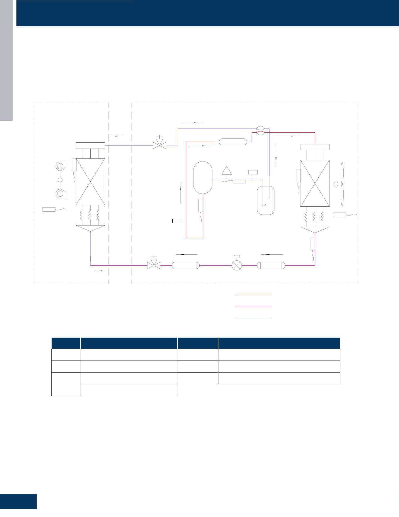
OPERATING FUNCTIONS AND CONTROLS
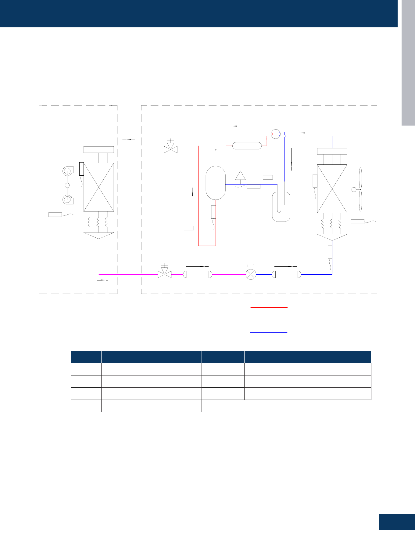
M
M
HPS
LPS
Sensor
Tc
Accumulator
Sensor
Td
Gas Stop Valve
with Service port
Ø15.88mm(5/8in.)(24k)
Ø19.05mm(3/4in.)(3036k&4248k)
Liquid Stop Valve
with Service port
Ø9.52mm(3/8in.)
Electronic expansion valve
EEV
High pressure
switch
Low pressure
switch
Low pressure
Service port
High temperature,high pressure,gas
High temperature,high pressure,liquid
Low temperature,low pressure,gas/liquid
Cooling
Indoor unit
Sensor
TM
FAN-IN
Outdoor unit
Filter Dryer
Filter
Sensor
Te
Sensor
Tao
FAN-OUT
Sensor
Ts
Silencer
4-way valve
ES
D
C
Heat Exchanger
Heat Exchanger
Compressor
INV
Sensor
Tai
Sensor Denition Sensor Denition
Td Compressor discharge sensor Te Outdoor coil out sensor
Tc Coil temperature sensor Ts Compressor suction temperature sensor
Ta o Outdoor air temperature Ps/Pd Pressure switch
Ta i Indoor air temperature
Cooling Mode
When the outdoor unit receives the startup signal of the thermostat, it will enter the cooling startup pre-processing stage. If 5 minutes have
passed since the last shutdown, the outdoor fan will immediately turn on, and the compressor will turn on 30s later. After each shutdown, it will
wait 5 minutes before it is turned on again. Wait 3 minutes for the rst power-on.
With the compressor operating, refrigerant will begin to ow throughout the refrigeration circuit. The operating frequency of the compressor
will be displayed on the Service Monitor Board.
INTRODUCTION
A7
ENGLISH
OPERATING FUNCTIONS AND CONTROLS
Sensor Denition Sensor Denition
Td Compressor discharge sensor Te Outdoor coil out sensor
Tc Coil temperature sensor Ts Compressor suction temperature sensor
Ta o Outdoor air temperature Ps/Pd Pressure switch
Ta i Indoor air temperature
Heating Mode
When the outdoor unit receives the heating start signal from the thermostat, if the compress-o downtime meets the minimum standby
time, the four-way valve will be powered on until the compressor starts, and the four-way valve will be reversed after the external fan
starts. The minimum standby time is 5 minutes, and the initial power-on is 3 minutes.
With the compressor operating, refrigerant will begin to ow throughout the refrigeration circuit. The operating frequency of the
compressor will be displayed on the Service Monitor Board
ES
DC
M
M
HPS
LPS
Sensor
Tc
Accumulator
Electronic expansion valve
EEV
High pressure
switch
Low pressure
switch
Low pressure
Service port
High temperature,high pressure,gas
High temperature,high pressure,liquid
Low temperature,low pressure,gas/liquid
Heating
Indoor unit
Outdoor unit
Silencer
4-way valve
Heat Exchanger
Heat Exchanger
Compressor
INV
FAN-IN
FAN-OUT
Filter Dryer
Filter
Sensor
Te
Sensor
Tao
Sensor
Ts
Sensor
TM
Gas Stop Valve
with Service port
Ø15.88mm(5/8in.)(24k)
Ø19.05mm(3/4in.)(3036k&4248k)
Liquid Stop Valve
with Service port
Ø9.52mm(3/8in.)
Sensor
Td
Sensor
Tai
INTRODUCTION
A8
ENGLISH
OPERATING FUNCTIONS AND CONTROLS
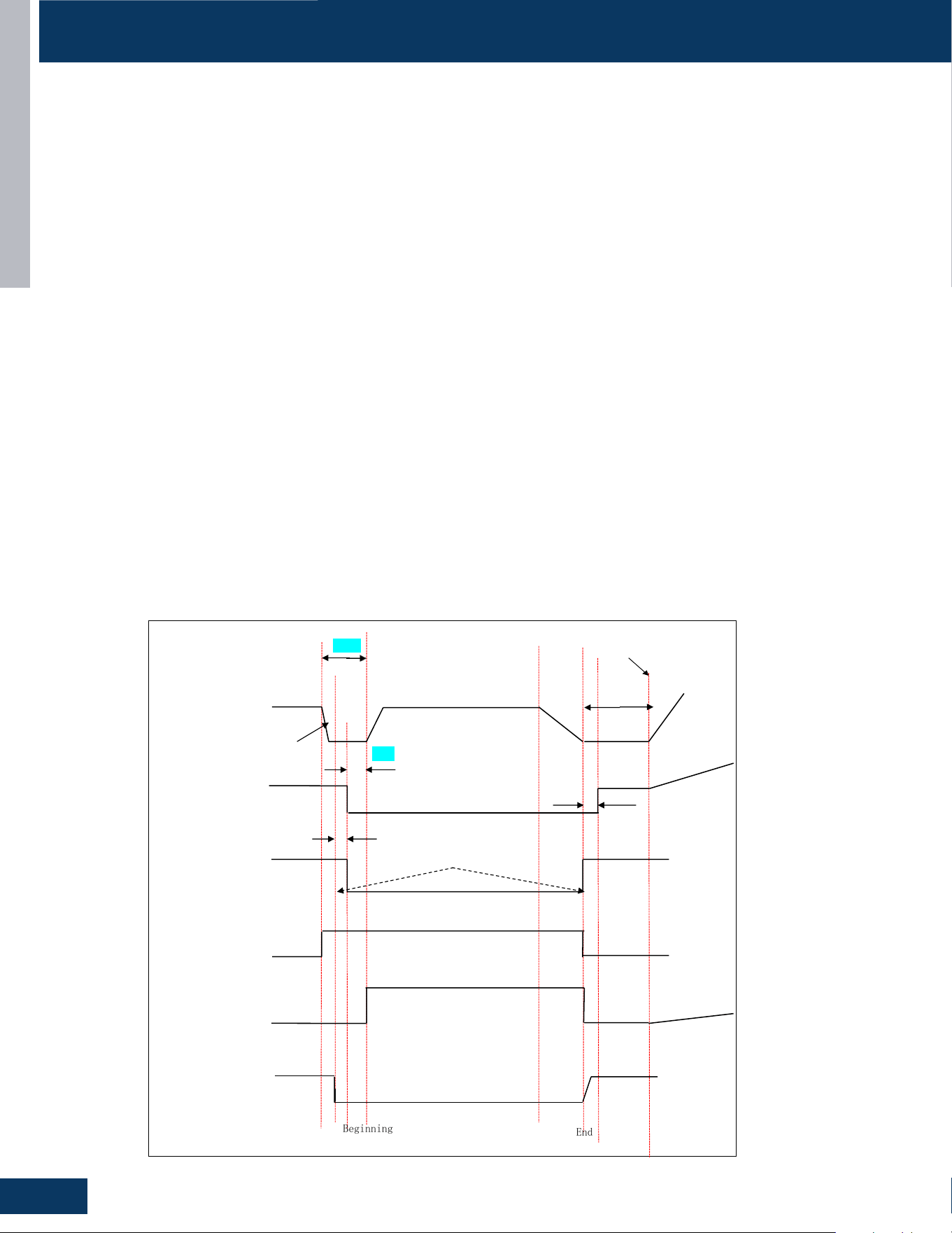
The defrosting control sequence diagram is as follows:
Defrost start
120 s 1Hz/s decrease Defrosting control is over
Automatic frequency amplification
Current frequency of inverter compressor Defrost frequency H
50Hz(E
150s
)
Enter frequency A 50HZ(E) Exit frequency B 40HZ(E)
Fast frequency reduce 1Hz/s
75 s
ODU Fan motor ON ON( Rotational speed before defrosting )
3S Auto fan speed
OFF
15 s
4-way valve Send defrost start and end signals to theIDU O
ON
N
O
OFF
N
Unloading valve SV1 Current Status Auto
Defrost opening degree (E)
Expansion valve PMV Automatic opening degree 120puls Automatic opening degree
IDU Fan speed
Anti cold fan operatioON
n
Defrosting process description:
除霜开始,压机先快速降频至50Hz(E),降频开始30秒后向室内发除霜信号,除霜信号发出15秒后,同时关外风机和
四通阀,压缩机在当前频率 50HZ(EE)继续运转 75 秒,在此期间膨胀阀保持自动开度;此预除霜段结束后按 1HZ/S 快
速上升至目标除霜频率 H=85HZ(EE),此除霜频率不受静音频率和环境温度限频频率限制,同时调整阀开度为 250(EE),
进入主除霜过程;
退出除霜时,先把频率降到40Hz(EE),四通阀上电,外风机延后四通阀3秒上电(外风机可滞后四通阀3秒,防止同步启
动电流增大),同时发除霜结束信号,压缩机在此频率继续在此频率 40HZ(E)下运转 150S(E),此 150 秒内电子膨胀阀开度
为 120 步,外风机执行进入除霜前风速继续运转 150 秒;然后压缩机,电子膨胀阀,外风机进入自动控制运转。
膨胀阀在机器退出除霜后,执行除霜进入
前开度,在此基础上进行自动调节
除霜结束后,内机按防冷风进行风机运转处理。
在外机发除霜结束信号给内机后的 6 分钟内,如果内机再发出手动除霜或除霜信号,外机不做处理(即不进入
OFF
Beginning
End
Defrost Operation
In the heating mode and along with the ambient sensor, the defrost sensor monitors the temperature of the outdoor coil to determine if defrost
is needed. If the compressor has been running for 10 minutes continuously and for 45 minutes overall, the dierence between the ambient
sensor (Ta) and the defrost sensor (Te) will be checked. The system will initiate the defrost cycle if the following conditions can be met for 5
continuous minutes:
Te ≤ C x Ta-A
Te: Defrost temperature sensor
Ta: Ambient temperature
C: If Ta < 32°F/0°C then C=0.80, If Ta≥ 32°F/0°C then C=0.60
A: 8, moderate climate (factory setting) 6, severe climate (alternate setting)
End defrosting: If the defrost sensor (Te) detects the temperature of the outdoor coil is above 44°F (7°C) for 60 seconds or is above 54°F
(12°C) for 30 seconds, the defrost cycle will terminate. If these temperatures cannot be reached, the defrost cycle will automatically terminate
in 10 minutes.
Timed Defrost Option (SW1-4 ON): When the outdoor ambient temperature sensor (Ta) detects temperature less than 32°F (0°C), In heating
mode, if the compressor runs continuously for 60 minutes or cumulatively for 240 minutes the system will defrost. Defrosting frequency is 68
HZ, with a defrosting time of 60 minutes.
Strong Defrost Control
Remote controller: When ODU is in heating mode or shutdown state, set fan to high speed and temperature to 30°C. Press the sleep button six
times within 5 seconds. After the buzzer sounds three times, the unit will enter manual defrost mode.
Wired controller: Heating mode, set fan to high speed and temperature to 30°C, and press button 6 times.
ODU dip switch: Service monitor board SW1-1~SW1-4 from o-o-o-o to o-o-o-on.
End defrosting: If the defrost sensor (Te) detects the temperature of the outdoor coil is above 44°F (7°C) for 60 seconds or is above 54°F (12°C)
for 30 seconds, the defrost cycle will terminate. If these temperatures cannot be reached, the defrost cycle will automatically terminate in 10
minutes.
INTRODUCTION
A9
ENGLISH
OPERATING FUNCTIONS AND CONTROLS
Dry Mode (Dehumidifying Mode)
When Tai>Tset+2°C, the indoor unit mode is the same as that of the
cooling operation, and the fan speed is also controlled according
to the cooling mode in auto mode. The working mode sent to the
outdoor unit is cooling mode.
When Tset<Tai≤Tset+2°C, the operating mode sent by the indoor unit
to the outdoor unit is dehumidication.
The indoor unit sends dehumidication mode to the outdoor unit,
under the following conditions:
• Condition A: Indoor unit operates for 10 minutes with the indoor
fan at low speed.
• Condition B: Indoor unit stops for 6 minutes with xed S-Code=0
and the indoor fan stops.
Conditions A and B alternate during operation.
When Tai ≤ Tset, the operation mode sent to the outdoor unit is
shutdown. If the ambient temperature is less than 16°C, the indoor
unit fan will be stopped, otherwise it will continue to blow low fan
speed.
Auto Restart
When this is enabled, the following functions will automatically
resumes after a power loss: ON/OFF State, Mode of Operation, Fan
Speed, Temperature Set Point, Louver Swing settings. If there was
a timer set or the system was in Sleep mode, they will be canceled
upon restart.
Wired Controller:
Auto Restart is enabled by Default.
Wireless Controller:
Enable: Press the Sleep button 10 times within 7 seconds. You will
hear 4 beeps as conrmation.
Disable: Press the Sleep button 10 times within 7 seconds. You will
hear 2 beeps as conrmation.
Note: When both a wired controller and a wireless controller are present,
only the wired controller’s auto restart takes eect. The wireless
controller can be congured, but its settings will be overwritten to match
the state of the wired controller.
Compressor and Outdoor Fan
Compressor
The compressor will start in low frequency. After a brief time delay, the compressor will come up to operating speed to meet the demand
requirement for capacity.
Outdoor Fan:
When adjusting the fan speed, the unit should remain at each speed for 30+ seconds to avoid speed-change malfunctions. In Cooling Mode, the
wait time between speed levels should be 15 seconds.
Cooling or Dehumidifying Mode: Five seconds after compressor starts, the outdoor fan will start running at medium speed. After 30 seconds,
it begins to control the fan speed according to the temperature conditions of the outdoor environment.
ODU Fan and Compressor Speed Logic
(Tao: Outdoor Air Temperature, Tc: Outdoor Coil Temperature, Te: Outdoor Coil Out temperature)
1. Compressor target speed in defrosting: 24K-60rps, 30K-80rps, 36K-60rps
2. Oil Return frequency: 50rps
3.1. Cooling fan control: each speed change interval of at least 45s
Priority control conditions:
• Tao≥40°C, ODU fan speed 7
• Tao≥32°C, ODU fan speed 6
Control of speed increase:
• Tc>35°C, ODU fan speed from the stop to 1
• Tc>36°C, ODU fan speed step by step from 1 to 5
• Tc>45°C, ODU fan speed from 5 to 6
3.2 Heating fan control: each speed change interval of at least 45s
Priority control conditions:
• Tao<5°C, ODU fan speed 6
Control of speed decrease:
• Te>12°C, ODU fan speed 5
• Te>10°C, ODU fan speed step by step from 5 to 1
Control of speed increase:
• Tc<4°C, ODU fan speed step by step from 1 to 5
• Tc<2°C, ODU fan speed from 5 to 6
Speed level 1G24ED2BEA 1G3036ED2BEA
1 250 250
2 350 300
3 400 400
4 490 500
5 600 550
6 680 650
7 720 700
INTRODUCTION
A10
ENGLISH
OPERATING FUNCTIONS AND CONTROLS
Fan Logic after Reaching Target Temperature
SW1_7 defaults to OFF: In cooling mode, both compressor and fan are stopped when the target temperature is reached.
SW1_7 set to ON: In cooling mode, the compressor stops but the fan continues to run when the target temperature is reached. In heating
mode, both compressor and fan are stopped when the target temperature is reached. In fan mode, the fresh air remains on regardless of
compressor status.
Fan Logic for Residual Heat Discharge
When heating is shut down, or energy demand S-code=0, or outdoor compressor is OFF: The indoor fan operates at low speed until coil
temperature <20°C (if outdoor temperature ≤10°C) or coil temperature <18°C (if outdoor temperature >10°C), then the indoor fan stops.
From receiving the shutdown signal to nal shutdown, the maximum operating time shall not exceed 50 seconds.
Note: S-code (no energy demand, for example, when the unit reaches the temperature)
Mode US24LB2BEA US24MB2BEA US30LB2BEA US30MB2BEA
Cooling 70 70 75 75
Heating 110 110 110 110
Defrosting 60 60 80 80
Mode US36LB2BEA US36MB2BEA
Cooling 70 70
Heating 110 110
Defrosting 60 60
Maximum Compressor Frequency (Hz)
Mode GS24WP2BEA QS30WP2BEA QS36WP2BEA
Cooling 66 75 75
Heating 101 90 93
Defrosting 60 80 80
Outdoor Unit Electronic Expansion Valve (EEV)
When unit starts, the EEV valves will energize and change to a standard opening. When operation starts, the EEV will change position to keep
the suction vapor superheat level at around 10°F. The EEV routinely opens and closes to maintain the compressor discharge temperature
within an acceptable range.
When the unit is shut o the opening size of the expansion valve of the indoor unit is 5 steps.
Electronic characteristics
Max. open angle 470 pulses
Open angle limitation of EEV
Unit stop Max. open angle Thermostat OFF Min. open angle
Cool/ dry 5 pulses 470 pulses 200 pulses 80 pulses
Heat 50 pulses 470 pulses 200 pulses 76 pulses
compressor ON
OFF
4-way valve ON
OFF
20S
2 minutes
Four-Way Valve Control
Under heating mode, the four-way valve opens. If the compressor does not start or changes to a non-heating mode, the compressor will be
stopped for 2 minutes, and then the four-way valve will shift.
When the compressor starts in the heating mode, there is a 20s delay before power is applied to the 4-way valve to switch the ow of hot
refrigerant to the indoor coil. When the call for heat is satised and the compressor shuts o, a 2-minute delay will occur before the 4-way valve
is powered down and switches back to the at-rest (cooling) position.
If the 4-way valve does not switch into the heating mode, after 10 minutes of compressor run time and the indoor coil temperature is below
81°F/27°C, the compressor will stop and the unit will display a 17-ash error code on the outdoor PCB.
INTRODUCTION
A11
ENGLISH
OPERATING FUNCTIONS AND CONTROLS
Base Pan Heater
Power supply:196~254VAC
Logic During Normal Operation
(Tao: Outdoor Air Temperature)
Tao≤-11°C for 5 minutes:
1. -16°C≤Tao≤-11°C, the base pan heater on for 10 minutes, o for 20 minutes, cycle on.
2. -20°C≤Tao<-16°C, the base pan heater on for 20 minutes, o for 10 minutes, cycle on.
3. Tao<-20°C, permanently on.
Note: 1, 2 must execute a loop before proceeding to the next judgment. When 1 or 2 switches to 3, executes immediately.
Turns o when any of the following conditions are met:
1. The compressor stops running.
2. No heating mode.
3. Tao≥-9°C for 5 minutes.
Model Pan Heater Resistance Value
1G24ED2BEA 0150831548C
1.220V/180W,(power range 162~198W)
2. Cold voltage: 1500V/min, hot voltage: 1200V/min
3. The cold insulation resistance is 500MΩ, and the hot insulation resistance is 50MΩ
4. Resistance Value: 268.8Ω
1G3036ED2BEA 0151045703
1.220V/180W,(power range 162~198W)
2. Cold voltage: 1500V/min, hot voltage: 1200V/min
3. The cold insulation resistance>500MΩ The hot insulation resistance>50MΩ
4. Resistance Value: 268.8Ω
Compressor Heater Band
Operating Logic
(Tao: Outdoor Air Temperature Td: Discharging Temperature)
Power supply:196~254VAC
Heater OFF Heater ON
Tao>50°F(10°C) or Td≥68°F(20°C) 100%*60min 0
41°F(5°C)<Tao≤50°F(10°C) and Td<68°F(20°C) 50%*60min 50%*60min
32°F(0°C)<Tao≤41°F(5°C) and Td<68°F(20°C) 33%*60min 66%*60min
Tao≤32°F(0°C)and Td<68°F(20°C) 0 100%*60min
Model No. Resistance Value
1G24ED2BEA
Rated voltage AC220V, Power 27W±7%,
Resistance: 1793Ω±7%
1G3036ED2BEA
In defrosting mode, the following conditions will apply:
Condition Pan Heater
Tao≤0°C On
Condition Pan Heater
10 minutes after defrosting OFF
Note:
AHRI STANDARD, as soon as the unit enters defrosting mode, the base pan heater starts;
AHRI STANDARD, Tao<-2°C, the base pan heater starts and stops the operation alternately at a 10-minute cycle.
After defrosting mode, the following conditions will apply:
Capacity Loss Per Piping Length
Unit BTU Unit Tons Vapor Line Size Pressure Drop PSI/100 ft.
Equivalent Length/Cooling Capacity Loss(%)
25 ft. 50 ft. 80 ft. 100 ft. 125 ft. 150 ft.
24000 2
5/8 7.2 1.8 3.6 5.8 7.2 9 10.8
3/4 2.5 0.6 1.3 2 2.5 3.1 3.8
36000 3
3/4 5.1 1.3 2.6 4.1 5.1 6.4 7.7
7/8 2.8 0.7 1.4 2.2 2.8 3.5 4.2
INTRODUCTION
A12
ENGLISH
SPECIAL FUNCTIONS AND CONTROLS
Cold Air Prevention
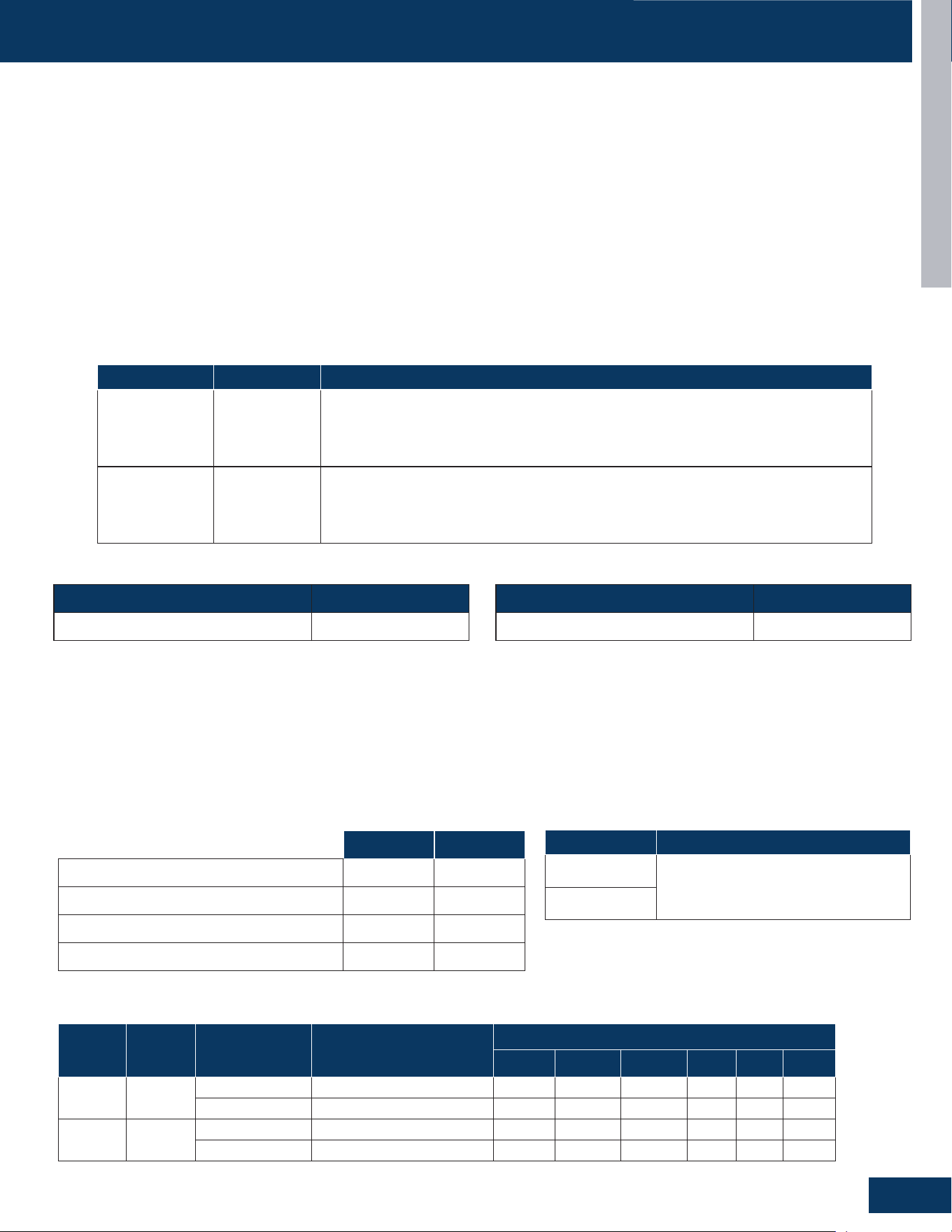
In heating , the operating state of the indoor fan is controlled according to the indoor coil temperature (Tm) after the compressor is started. For
specic operations, refer to the following gure.(The temperature control point in parentheses is when Tao is greater than 10°C)
INTRODUCTION
A-7
ENGLISH
FUNCTIONS AND CONTROL
Heating Operation Mode
Overview
The temperature control range in heating mode is -4°F - 75°F. The
temperature set by the remote control and the indoor unit ambient
temperature sensor will determine if a call for heat is needed. If a call for
heat is justifıed, a temperature compensation adjustment is automatically
added to the operating parameter and the call is communicated from the
indoor unit to the outdoor unit.
The indoor unit louver will open using a stepper motor. The indoor fan will
not operate at this time.
The outdoor unit will shift the 4-way valve to the heat mode position
and determine the position of the EEV and speed (frequency) of the
compressor. There can be a delay of up to 3 minutes before the outdoor
unit fan and compressor start.
The predetermined conditions for automatic control are follows:
Note: The heating mode has a temperature compensation of 4 °C, resulting
in the actual ambient temperature being subtracted from the calculation by
approximately 7 °F.
As the indoor ambient temperature falls, the change of fan speed follows
the following temperature conditions:
4. Coil temperature is higher than 37°C/ 100°F, fan speed according to
the set operation.
5. When the coil temperature drops, the fan speed is judged according
to the hot cross temperature:
6. Coil temperature is higher than 35°C, fan speed according to the set
operation.
Residual heat sending: the indoor fan will operate on low speed until the
coil temperature reaches 73°F or stop after 50 seconds.
The outdoor unit temperature sensors: outdoor ambient, defrost, suction
line, and compressor discharge, used in conjunction with the indoor coil
and room temperature sensors, provide information to the outdoor control
board to monitor the system and regulate the speed of the compressor, the
EEV and outdoor fan speed to achieve the desired room temperature.
When heating has been satisfıed, the compressor will turn off fırst, followed
by the outdoor fan. The 4-way valve will de-energize 2 minutes after
compressor stops.
To save energy, The indoor unit fan will continue to run at minimum speed
until indoor coil temperature reaches a minimum temperature, when it will
turn off.
If the system detects a malfunction, it may shut down or show an error
code on the indoor unit display board and/or I outdoor unit main board
LED.
Defrost
When the system initiates a call for defrost, the indoor fan motor stops. The
indoor unit display will not change. Any indoor unit malfunctions will be
ignored at this time. The system will cycle through the defrost operation.
Any indoor unit malfunctions will be ignored until the compressor restarts
and has been operating for 30 seconds. At the conclusion of the defrost
cycle, the indoor fan will enter the cold air proof operation. Heat mode
resumes.
Automatic Heating Temperature Compensation
When the system is in heating mode, a temperature compensation
adjustment is added to the sensed temperature. This is intended to adapt
for temperature stratifıcation in the conditioned environment relative to the
installation location of the indoor head.
Indoor Unit
To enter the heat mode, point the infrared remote controller at the indoor
There will be a 3 minutes delay when switching from high speed fan to low
speed fan. There will be no delay when switching from low speed fan to
high speed fan..
Cold Air Proof Operation
At initial start of heat mode, indoor blower will not be turned on
immediately until indoor coil temperature senses a minimum temperature.
This prevents cold air from being blown until the coil is heated.
Fan Speed Ambient Indoor Air Temperature
Stop 8.8°F and higher above setpoint
Low Between 5.9°F and 8.7°F above setpoint
Medium Between 3.6°F and 5.8°F above setpoint
High Below setpoint and up to 3.5°F above setpoint
The indoor fan is controlled based on the coil temperature, as shown in the
fıgure above.
31-5000931 Rev. 0
7. Coil temperature between 37°C and 35°C fan speed is mid;
8. Coil temperature between 35°C and 25°C fan speed is low;
10. The fan stops when the coil temperature is lower than 23°C;
9. Coil temperature between 25°C and 23°C fan speed is weak;
When the coil temperature rises, the fan speed is judged according to the
coil temperature:
1. At the end of heating or defrosting after the fırst power on, the fan
stops when the coil temperature is lower than 25°C/ 77°F;
2. Coil temperature between 25°C/ 77°F and 35°C/ 96°F fan speed is
weak;
3. Coil temperature between 35°C/ 96°F and 37°C/ 100°F fan speed is
weak;
Cold Air Prevention Logic after Defrosting
• When Tao ≤10°C, the fan starts low-speed operation once the pipe temperature rises from a lower temperature to 26°C.
The fan operates at the set speed when the pipe temperature continues to rise to 30°C.
• When Tao>10°C, the fan starts low-speed operation once the pipe temperature rises from a lower temperature to 30°C.
The fan operates at the set speed when the pipe temperature continues to rise to 34°C.
6.10.1
启动运转过程中防冷风控制
@82
在制热运转中,每次压机启动后根据室内盘管温度(Tm,写入 EEPROM)来控制室内风机
的运行状态,具体操作见下图:
Tm
Setting fan speed
30(34)
Low fan speed
26(30)
20(26) Close
18(20)
注:括号内的为室外温度大于 10 度时的温控点;
ECO Function
Entry condition
In the startup state, the IDU receive the remote controller, wired controller, and ECO button signal to realize the ECO function (or via app).
Temperature compensation is only compensated once upon entry, and the newly set temperature is no longer compensated during ECO
operation.
Function
ECO functions are eective for both cooling and heating modes.
1. In cooling mode, the user press the ECO button (or via APP) to enter the ECO function, and set the temperature 2 ° F (or 1°C) higher than the
current set temperature (The default is °F adjustment), which can be adjusted in the APP; The adjusted set temperature shall not exceed the
temperature range in 3 (below).
2. In heating mode, the user presses the ECO button (or via APP) to enter the ECO function, and set the temperature 2 ° F (or 1°C) lower than
the current set temperature (The default is °F adjustment), which can be adjusted in the APP; The adjusted set temperature shall not exceed
the temperature range in 3 (below).
3. After entering ECO mode, the set temperature range of cooling and heating is 60 ° F to 86 ° F, and the operating range of the set
temperature can be reduced through the APP (example: Set temperature range from 60 ° F-86 ° F to 70 ° F-80 ° F). Note: The maximum set
temperature≥the minimum set temperature, and the displayed set temperature changes together
4. In cooling mode, during ECO mode, when the set temperature reaches, via APP the user can stop the IDU fan (the ducted will reach the
temperature and stop the air by default, and other IDUs won’t.
5. The dierent Settings of ECO functions should be stored in the IDU. The settings remain the same the next time the unit enter eco mode.
Exit condition
In ECO mode, the IDU can exit the ECO mode only by pressing the ECO button or exiting from the APP.
Note: There is a dierence between temperatures in °F and °C. °F values remain normal. °C values are switched based on the conversion.
Forced Heating/Cooling
Outdoor unit dip switch setting(SW1), cooling 60HZ, heating 50HZ xed frequency operation.
Sw1 1 2 3 4 Description
Force
Mode
ON ON OFF OFF Forced cooling (For AHU and PRO)
ON ON OFF ON Forced cooling (For PRO)
ON ON ON OFF Forced heating(For PRO)

INTRODUCTION
A13
ENGLISH
SPECIAL FUNCTIONS AND CONTROLS
Temperature Compensation
Setting Temperature Compensation with Remote Control
The factory default setting is 0°C for heating mode.
1. Apply power to the unit.
2. Set to Heating Mode to set heating temperature compensation, or Cooling mode to set cooling temperature compensation.
3. Set the temperature at 24C.
4. Press the SLEEP button 7 times within 5 seconds.
5. The unit will beep 2 times to conrm.
6. Change the setting to the desired value as follows:
• If set to 24 (starting point), compensation is zero (0).
• If set to 25, compensation is - 1°C, the indoor ambient temperature is set to the current actual temperature minus 1°C.
• If set to 26, compensation is - 2°C, the indoor ambient temperature is set to the current actual temperature minus 2°C, and so on.
• If set to 23 compensation is +1°C, the indoor ambient temperature is set to the current actual temperature plus 1°C.
• If set to 22, compensation is +2°C, the indoor ambient temperature is set to the current actual temperature plus 2°C, and so on.
• Temperature Compensation can be adjusted from -8°C to +6°C
• To disable temperature compensation (compensation = zero), set to 24
7. Once the desired value has been selected, turn OFF the unit via the remote controller to save the compensation settings.
Example: If the unit is sensing 23°C ambient temperature and the compensation has been set to 26 (-2°C), then the logic will use 23-2 = 21°C as
room temperature and will show 21°C in the display.
Setting Temperature Compensation with Wired Controller
1. SW1-3 set to OFF (default is OFF).
2. With the display OFF, press & hold the FAN button for 5 seconds to enter temperature compensation interface.
3. The display will show 00 (default) or the current compensation value, in the top right corner of the display.
4. Use TEMP+/ TEMP- buttons to adjust the compensation.
5. Press MODE to conrm.
Notes for the wired controller:
• When it is Celsius, the range of compensation value is -4°C~ 4°C(0.5 increments). When it is Fahrenheit, the range is -8°F ~ 8°F (1.0 increments).
• Temperature compensation changes the ambient temperature reading. I.e.: If the system is sensing the ambient temperature at 72°F and the
compensation is set to -2°F then the system will use 70°F in its operation for heating and cooling modes.
• This setting will only be valid if SW1-3 is set to OFF.
INTRODUCTION
A14
ENGLISH
PROTECTION FUNCTIONS AND CONTROLS
Protection Controls
Low Load Protection Control
In order to prevent frosting of the indoor coil, the outdoor system will be stopped if the indoor coil temperature is 32°F for 5 minutes, but the
fan will continue to operate. The outdoor system will restart when the indoor coil is above 50°F, and the system has been stopped for 3 minutes.
The malfunction will be stored in the malfunction memory and will not be displayed.
High Load Protection Control
The system will be stopped if the indoor coil temperature is above 149°F for 2 minutes. The indoor fan will be controlled by the thermostat.
The outdoor system can be restarted when the indoor coil temperature is below 108°F and the system has been stopped for 3 minutes. The
malfunction will be stored in the malfunction memory and will not be displayed.
Antifreezing Protection (Highwall Only)
Prevents freeze-up of the indoor coil. The indoor unit coil temperature sensor will shut o the outdoor unit and begin a defrosting routine if
the indoor coil is below 32°F for more than 2 minutes. The indoor unit will not report this operation. Once the indoor coil warms up, the system
will re-enter cooling mode and operate normally, This protection cycle prevents the indoor coil from developing ice coating during low heat
load operation.
Abnormality Conrmation Protocol
Indoor Temperature Sensor Abnormality: The normal temperature ranges from 120°F to -30°F. When the temperature goes beyond this range,
the abnormality can be conrmed. If the temperature goes back into the range, the system will automatically resume.
Indoor Heat Interaction Sensor Abnormality: The normal temperature ranges from 120°F to -30°F. When the temperature goes beyond this
range, the abnormality can be conrmed. If the temperature goes back into the range, the system will automatically resume.
Indoor/Outdoor Malfunction: When the indoor system receives the outdoor malfunction codes, it will store the code into E2 for the malfunction
list resume. The indoor system will continue to operate according to the original status, the malfunction code will not be displayed.
Communication Abnormality: If the indoor system can’t receive the outdoor system for 8 minutes, the communication abnormality can be
conrmed and reported and the outdoor system will be stopped.
Over-Temperature Heat Mode Indoor Coil
The over-temperature routine will protect the system from excessive high indoor coil temperature during heat mode operation. The routine
will initiate if the indoor coil temperature sensor reads temperatures in excess of 131°F. Conditions that cause high indoor coil temperature
include indoor fan failure, dirty indoor coil and operating the system in heat mode when outdoor air temperatures exceed operating limit.
Should this routine be initiated, the system will reduce compressor frequency until the indoor coil temperature reaches 117°F. Once this is
achieved, the system will return to normal operation.
INTRODUCTION
A15
ENGLISH
PROTECTION FUNCTIONS AND CONTROLS
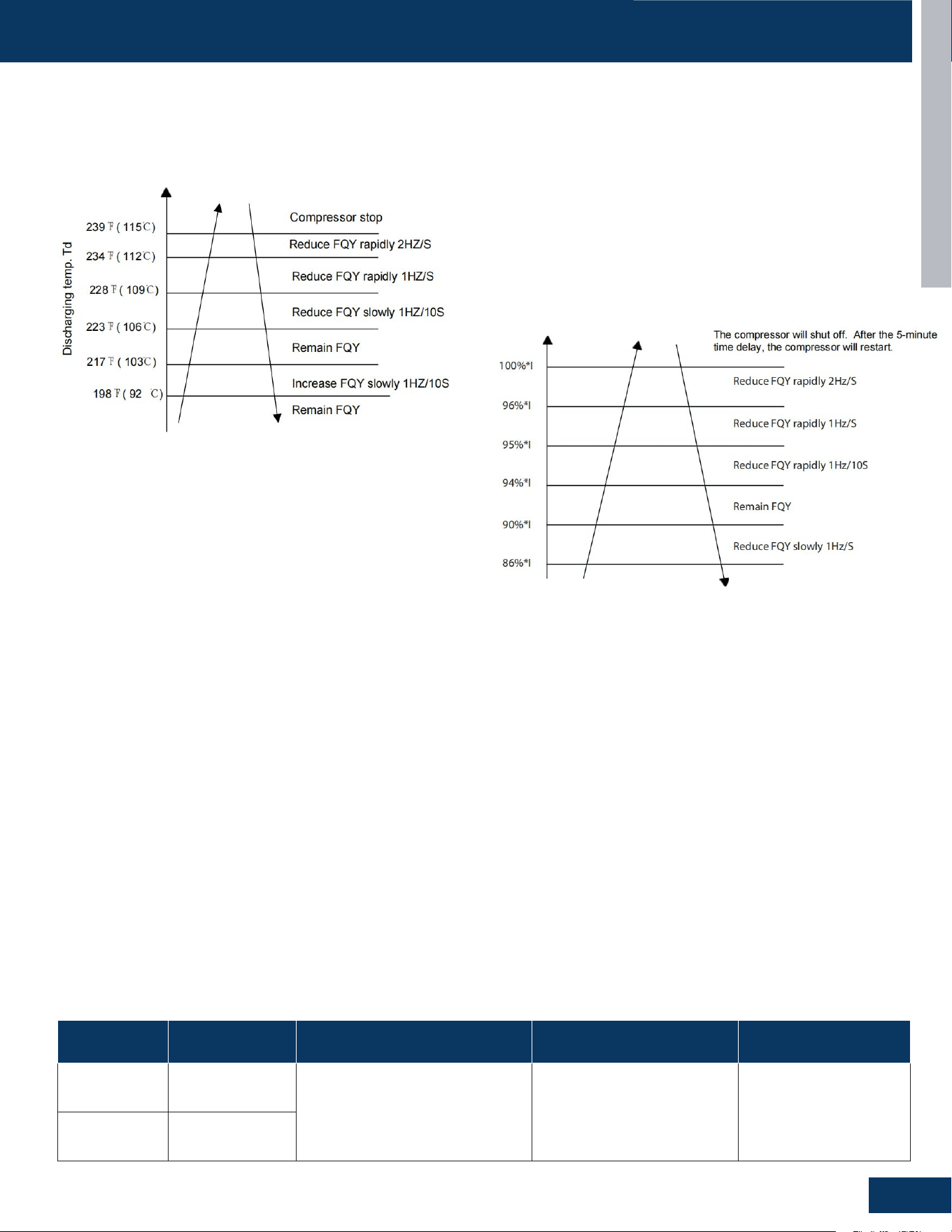
Compressor/High Current Protection
When the current of compressor exceed the the value of limit value,
the compressor stop, and report the error.
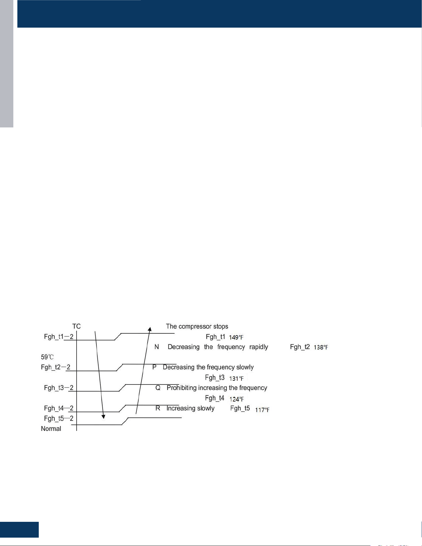
Compressor Discharge Protection
If the discharge temperature is higher than normal, the compressor
will slow down to lower the temperature. If the discharge
temperature sensor reaches 239F for 10 seconds, the compressor
will shut o. After the 5-minute time delay, the compressor will
restart.
Model
Compressor Over
Current Protection
Compressor Discharge protection Module Thermal Overload Low Voltage
1G24ED2BEA 20A
1.Discharing temperature≥103°C
(217.4°F), compressor limit frequency
2.Discharing temperature≥115°C
(239°F), stop the unit
Module temperature≥80(176°F),
compressor limit frequency
2.Module temperature≥95°C
(203°F), stop the unit
Voltage no exceed
208/230V
(rated voltage)±20%
1G3036ED2BEA 23A
Discharge temperature (Td) too high. Compressor reduce frequency
according to the outdoor air temperature (Tao). If the discharge
temperature still exceeds the limit value, it will report the error.
1. > 239°F (115°C) — Critical Shutdown
• If the discharge temperature exceeds 239°F (115°C) for 10
seconds, the compressor shuts o immediately.
• A 5-minute delay is imposed before restart is permitted.
• Restart Condition: Compressor restarts only if Td has dropped
below 221°F (105°C) after the delay.
Error Code 08 will be shown when this condition is triggered.
No hard lockout is enforced as the system will continue retrying after
each 5-minute timeout, assuming temperatures recover.
2. 234–239°F (112–115°C) — Aggressive Ramp-Down
• The compressor frequency is reduced at 2 Hz per second until
temperature drops into a safer range.
3. 228–234°F (109–112°C) — Standard Ramp-Down
• The system lowers compressor frequency at a moderate 1 Hz
per second.
4. 223–228°F (106–109°C) — Gentle Ramp-Down
• The system decreases frequency at 1 Hz every 10 seconds,
allowing gradual cooling without drastically impacting capacity.
5. 217–223°F (103–106°C) — Stable Zone
• The compressor holds its current operating frequency without
adjustment.
• This zone is considered safe but closely monitored.
1. At 100% Current
• If the current reaches 100% of its rated value, the compressor
shuts o to prevent damage.
• The system waits for 5 minutes before restarting the
compressor.
2. Between 96% and 100% of I
• The compressor frequency is rapidly reduced at 2Hz per second.
3. Between 95% and 96% of I
• The frequency is reduced more slowly at 1Hz per second.
4. Between 94% and 95% of I
• The frequency is reduced gradually at 1Hz every 10 seconds.
5. Between 90% and 94% of I
• The compressor operates at its current frequency without
adjustments.
6. Below 90% of I
• The compressor frequency increases slowly at 1Hz per second,
restoring normal operation.
Note: I is rated current.
6. 198–217°F (92–103°C) — Recovery Zone
• As discharge temperature drops below 217°F, the system begins
to gradually increase compressor frequency at 1 Hz every 10
seconds, allowing return to full performance.
7. < 198°F (92°C) — Normal Operation
• No protective adjustments are made.
• Compressor operates freely per demand and load conditions.
INTRODUCTION
A16
ENGLISH
PROTECTION FUNCTIONS AND CONTROLS
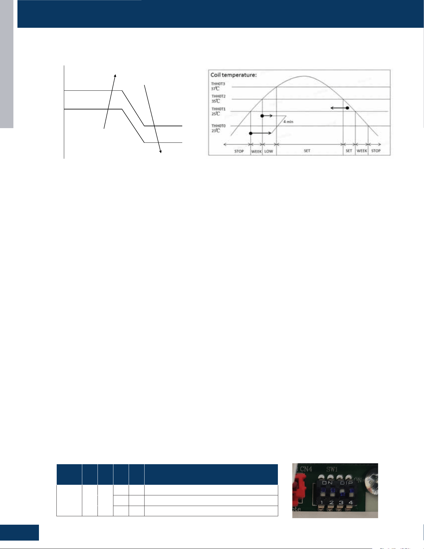
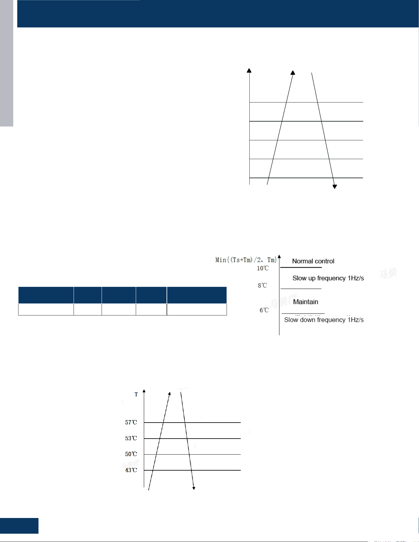
Indoor Coil Thermal Overload Protection in Heating Mode
Indoor heat exchanger sensor tests the temperature of the indoor heat exchanger. If the temperature is higher than 53°C, the compressor
speed is reduced. If the temperature of the indoor heat exchanger is lower than 43°C, normal control is restored.
TROUBLESHOOTING & REFERENCES
PAGE 18
ENGLISH
SpecicationsSpecications
Functions and Control
Indoor antifreeze protection
When Min{(Ts+Tm)/2, Tm} ≤6 ° C, the compressor frequency decreases at a rate of 1Hz/10s.
When TM starts to rise and 6 ° C ≤ Min{(Ts+Tm)/2, Tm}≤8 ° C, the compressor frequency remains unchanged.
When 8 ° C < Min{(Ts+Tm)/2, Tm}≤10 ° C, the compressor speed at 1Hz/10s.
Compressor Over current Protection
Compressor speed Normal control Increase 1Hz/10sec Decrease 1Hz/sec Freezing point(Compressor stops)
Min{(Ts+Tm)/2,Tm} 6-8° C 8-10° C 2-6° C <2° C for 10 seconds
Indoor heat exchanger sensor tests the temperature of the indoor heat exchanger. If the temperature is higher than 53°C,
the compressor speed is reduced. If the temperature of the indoor heat exchanger is lower than 43°C, normal control is
restored.
Indoor coil thermal overload protection in Heating mode
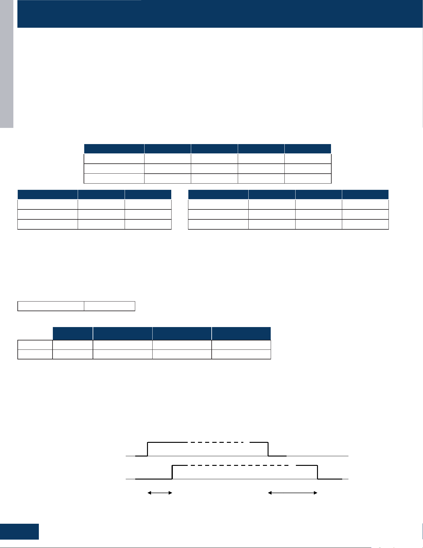
The speed of fan gradually decreases from the current speed until it stops
The speed of compressor
gradually decreases from the
current speed until it stops
P drops rapidly, and the compressor resumes
operation when the temperature drops to 53°C
Q remains unchanged
R rises slowly
Normal control
Compressor Speed
Normal
Control
Increase
1Hz/10sec
Decrease
1Hz/sec
Freezing Point
(Compressor Stops)
Min{(Ts+Tm)/2,Tm} 6-8° C 8-10° C 2-6° C <2° C for 10 seconds
Indoor Antifreeze Protection
When Min{(Ts+Tm)/2, Tm} ≤6 ° C, the compressor frequency decreases at a rate of 1Hz/10s.
When TM starts to rise and 6 ° C ≤ Min{(Ts+Tm)/2, Tm}≤8 ° C, the compressor frequency remains unchanged.
When 8 ° C < Min{(Ts+Tm)/2, Tm}≤10 ° C, the compressor speed rises at 1Hz/10s.
Low Pressure Protection
With the compressor running, if the low pressure switch opens for 1
minute, the compressor will stop.
If this condition occurs 3 times in an hour, the compressor will lock
out and a low pressure error code will be displayed at the indoor unit.
If the compressor is not running and the switch opens for 30 seconds,
a low pressure error code will be displayed.
The low pressure switch does not stop compressor operation or
signal an error code during the the rst 8 minutes of run time when
the compressor starts a new cycle.
During defrost, within 6 miutes afer the defrost and duting oil return,
shield low pressure switch
High Pressure Protection
High Pressure Protection in Cooling
The compressor will
shut o. After the
5-minute time delay, the
compressor will restart.
Reduce FQY rapidly 2Hz/S
Reduce FQY slowly 1Hz/S
Remain FQY
Raise FQY slowly 1Hz/10S
135
O
F(57
O
C)
Tc--cooling
138
O
F(59
O
C)
145
O
F(63
O
C)
149
O
F(65
O
C)
154
O
F(68
O
C)
Remain FQY
INTRODUCTION
A17
ENGLISH
PROTECTION FUNCTIONS AND CONTROL
Send oil return signal oil return begins oil return over
60s ref. eliminated 30s
Oil return frequency auto frequency
Low frequency
Inverter compressor auto frequency
350 pulses(E)
running indoor EEV auto angle auto angle
120 pulses(E)
80(E)
stopped indoor EEV OFF angle 5(E) OFF angle 5(E)
Outdoor motor AUTO AUTO (TC or ambient temp. control) AUTO
running indoor motor AUTO AUTO (set fan speed) AUTO
stopped indoor motor STOP STOP STOP
4-way valve OFF OFF OFF
MULTI:
D: Entering Conditions
When the compressor running frequency is lower than 58Hz (E) continuously for 8 hrs, the system
will enter the oil return cycle.. In the course of mode changeover, manual unit stop or protective
unit stop, the time will be accumulative. After the compressor restarts up, the time will be counted
continuously. In a continuous 8 hrs, if the compressor running frequency is not less than 72Hz for
over 10 minutes continuously, the accumulative time will be cleared. Also after the heating
defrosting, the time will be cleared.
F: Error Code Occurrence During Oil Return Cycle
If the system stops during an oil return cycle due to an error code, the cycle timing will resume
when the system restarts after the error is cleared.
If there is a switch from heating to cooling, or from cooling to heating during the oil return cycle
timing, and the system stops due to an error code, the oil return cycle will occur immediately
when the error code is cleared.
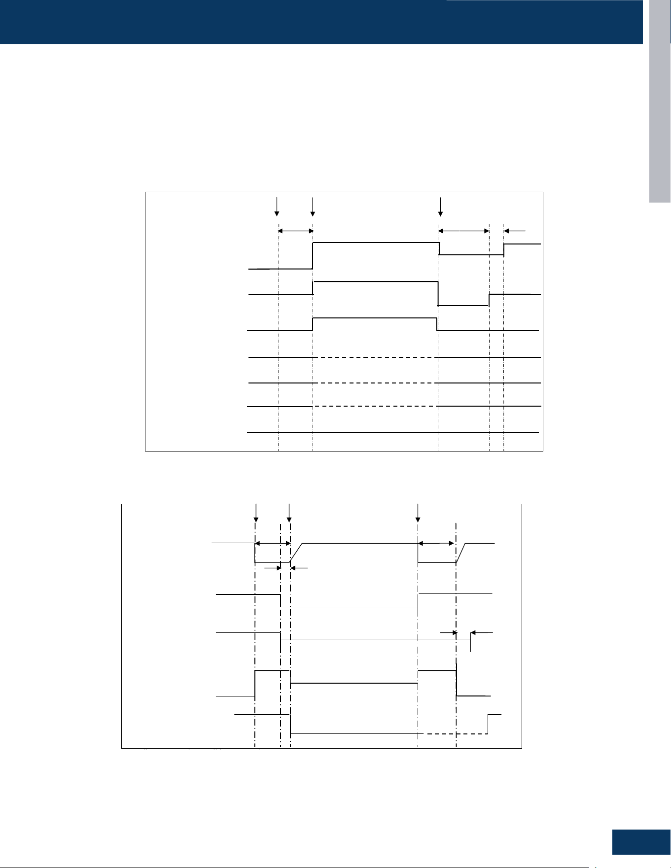
Oil Return in Cooling Mode:
Oil Return Cycle
When the compressor is operating at low load conditions, or the operating frequency has been below 70Hz continuously for 4 hours, the system
will enter the oil return cycle. This ensures that oil which may be trapped within the system at low loads will return to the compressor crankcase.
If a 4-hour low speed run time has occurred, the oil return procedure initiates by automatically ramping up the compressor speed to at least
85Hz for a pre-set time, up to a 9-minute maximum. The higher speed will wick hiding oil into the now faster-moving refrigerant and deposit it
in the compressor crankcase. To avoid occupant discomfort when the oil return cycle is active, the indoor fan shuts o.
Should an error code result in a system shutdown, the oil return cycle timing will resume when the error code has been cleared.
Oil Return in Cooling Mode
Oil Return Exit Conditions, Cooling:
1 minute later after oil return is over
& Td Tc‐ >86℉(30 ℃)
OR OR Ts Tc2AVE‐ >86℉(30 ℃)
Tc2AVE<
Max. 10 minutes
Oil Return in Heating Mode
Oil Return Exit Conditions, Heating:
Max. 9 minutes (E)
OR OR Td Tc‐ < for 30s continuously(5 minutes later, begin
to count)
& Ts Tc2AVE‐ < for 30s continuously(5 minutes later,
begin to count)
Running for min. 5 minutes
Send oil return signal oil return begins oil return over
Inverter compressor indicated FQCY 60s oil return FQCY 60s soft startup
0HZ 0HZ
5s
Outdoor motor AUTO AUTO
AUTO (TC control)
4-way valve ON
OFF 15s
450 pulses 450 pulses
350 pulses
All expansion valves auto angle auto angle
Indoor fan motor ON
OFF Cold air proving mode
-31℉(-35 ℃)
68℉(20 ℃)
59℉(15 ℃)
Oil Return in Heating Mode

[This page left intentionally blank]

OUTDOOR UNITS
B1
ENGLISH
OUTDOOR UNITS
TABLE OF CONTENTS
COMPONENTS .......................................................................................................................................................................B2
Component Overview ............................................................................................................................................................ B2
Heat Exchanger And Pipe .......................................................................................................................................................B4
Compressor ............................................................................................................................................................................B4
Heating Belt ............................................................................................................................................................................B4
Low Pressure Switch ...............................................................................................................................................................B4
High Pressure Switch ..............................................................................................................................................................B4
Gas-Liquid Segregator ...........................................................................................................................................................B4
Electronic Expansion Valve ....................................................................................................................................................B4
4-Way Valve .............................................................................................................................................................................B4
Fan ...........................................................................................................................................................................................B4
Fan Motor ................................................................................................................................................................................B4
PCB ..........................................................................................................................................................................................B4
Terminal Block for Power Supply ............................................................................................................................................ B4
Terminal Block for Controller .................................................................................................................................................B4
Terminal Block for Indoor Unit ...............................................................................................................................................B4
Accumulator ............................................................................................................................................................................B4
Silencer ....................................................................................................................................................................................B4
Service Monitor Board ............................................................................................................................................................ B4
PCB Overview .........................................................................................................................................................................B5
Light Board: 0151800609 .......................................................................................................................................................B6
WIRING DIAGRAM ................................................................................................................................................................... B7
DIP SWITCH SETTINGS
..........................................................................................................................................................B8
SERVICE PROCEDURES
........................................................................................................................................................B10
4-Way Valve ...........................................................................................................................................................................B10
Electronic Expansion Valve (EEV) ........................................................................................................................................B10
Outdoor Fan Motor ...............................................................................................................................................................B11
Temperature Sensor ............................................................................................................................................................. B11
Base Pan Heater .................................................................................................................................................................... B11
Compressor Heater Band ....................................................................................................................................................B11
1G24ED2BEA
1G3036ED2BEA
OUTDOOR UNITS
B2
ENGLISH
COMPONENTS
1
2
3
4
5
6
9
10
1
2
3
4
5
6
9
10
7
8
7
8
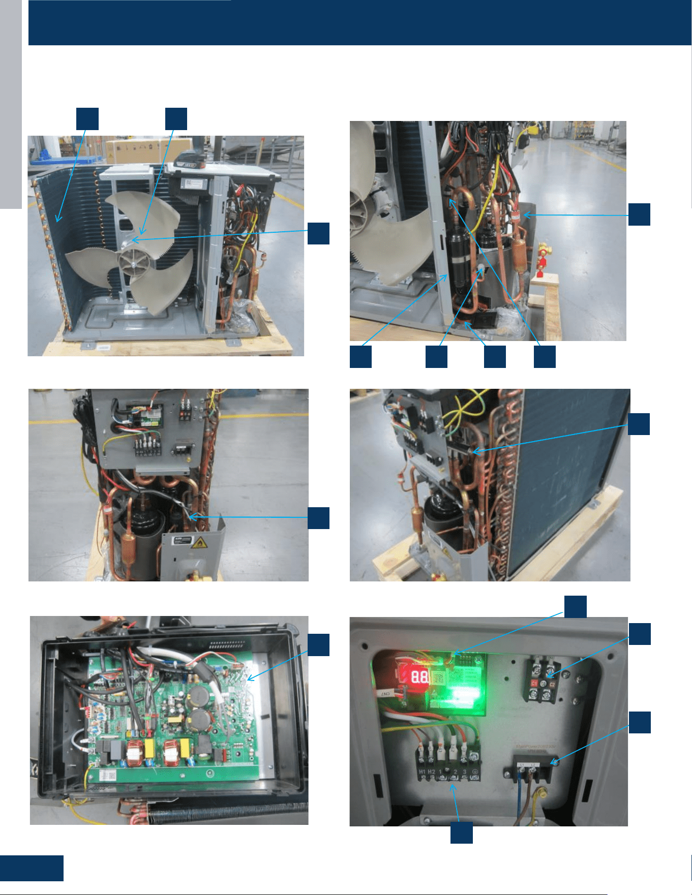
Component Overview
1G24ED2BEA
1 9
10
7
6 2 3 4
5
8
11
12
13
14
17
11
12
13
14
17
11
14
12
13
17
OUTDOOR UNITS
B3
ENGLISH
4
11
12
14
17
4
11
12
14
17
4
11
12
14
17
9
10
15
7
16
2
3
5
9
10
15
7
16
2
3
5
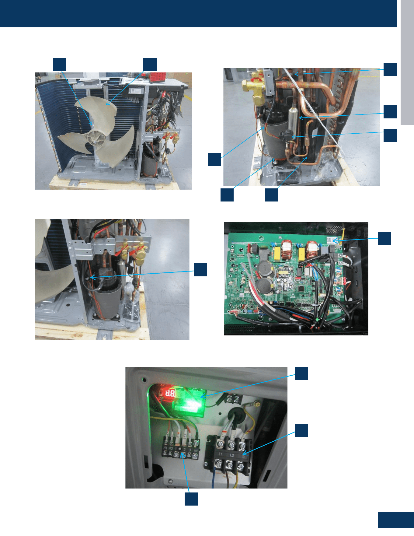
COMPONENTS
10 9
2
3
4
11
17
12
14
15
7
16
5
1G3036ED2BEA

OUTDOOR UNITS
B4
ENGLISH
COMPONENTS
Heat Exchanger And Pipe
Compressor
Heating Belt
The compressor heating belt is specically designed to
prevent freezing, icing, and potential malfunctions by
maintaining a consistent operational temperature. It
eectively safeguards the compressor from cold-induced
performance degradation or shutdowns in low-temperature
environments, ensuring continuous and reliable operation
while extending the equipment’s service life.
Low Pressure Switch
The low-pressure switch monitors the refrigerant system
pressure. It automatically shuts down the compressor when
pressure drops below the safe threshold, preventing damage
from insucient refrigerant, pipeline blockages, or leaks.
This safeguard ensures system eciency, avoids mechanical
failures, and prolongs equipment lifespan by halting operation
under abnormal low-pressure conditions. Trip Pressure:
0.03MPa.
High Pressure Switch
The high-pressure switch monitors refrigerant system
pressure. It trips to shut down the compressor when pressure
exceeds a safe level, preventing damage from overcharging,
condenser fouling, or blocked vents, and ensuring system
safety and reliability. Trip Pressure: 4.3MPa.
Gas-Liquid Segregator
The component separates liquid refrigerant from vapor
before it enters the compressor. This prevents liquid slugging,
which can damage the compressor by causing hydraulic
lock or mechanical stress. By ensuring only vapor enters the
compression chamber, it optimizes compression eciency,
reduces wear on moving parts, and minimizes the risk of
refrigerant oodback. This improves overall system reliability,
extends equipment lifespan, and maintains consistent cooling
performance by preventing operational disruptions caused by
liquid ingress.
Electronic Expansion Valve
It maintains optimal pressure and temperature balance
between the condenser and evaporator, ensuring ecient
heat transfer. By controlling the refrigerant supply according
to load variations, it prevents overfeeding or underfeeding,
which could lead to compressor damage or reduced
cooling capacity. This precise modulation enhances system
eciency, stabilizes superheat levels, and adapts to changing
operational conditions, ensuring consistent performance
while minimizing energy consumption.
1
2
3
8
9
10
11
12
13
14
15
16
17
4
5
6
7
4-Way Valve
The component reverses the refrigerant ow direction to
switch between cooling and heating modes. It redirects
high-pressure refrigerant from the compressor to either
the condenser (for cooling) or the evaporator (for heating),
altering the heat exchange process. This allows the system
to adapt to seasonal temperature needs, ensuring the indoor
unit can provide cool air in summer and warm air in winter. By
maintaining proper refrigerant circulation in each mode, it
prevents operational ineciencies and ensures the system
delivers consistent thermal comfort while optimizing energy
usage for both heating and cooling cycles.
Fan
Fan Motor
PCB (See page B5)
Terminal Block for Power Supply
Terminal Block for Controller
Terminal Block for Indoor Unit
Accumulator
The component collects and stores excess liquid refrigerant,
preventing it from ooding the compressor during low-
load operations or shutdowns. It ensures only vapor enters
the compressor by separating liquid refrigerant, avoiding
hydraulic damage from liquid slugging. By maintaining
a stable refrigerant inventory, it supports consistent
system performance, especially during start-up or when
load conditions uctuate. This helps regulate refrigerant
ow to the evaporator, prevents refrigerant shortages or
overcharges, and enhances overall system eciency by
minimizing energy waste and extending compressor lifespan
through reliable vapor-only compression.
Silencer
Service Monitor Board (See page B6)
OUTDOOR UNITS
B5
ENGLISH
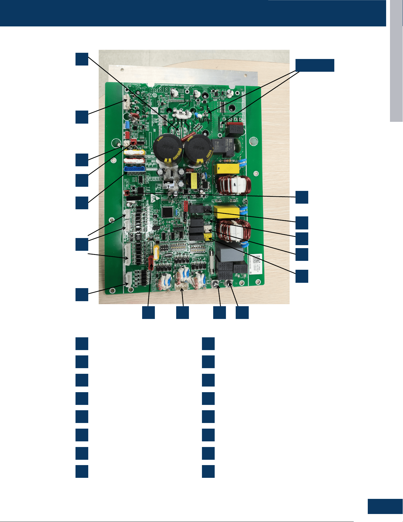
COMPONENTS
0151801031D
1 U1V1W1 Compressor
2 CN29 Fan motor
3 CN25 Low pressure switch
4 CN24 High pressure switch
5 CN21 Temperature sensor
6 CN13 CN14 CN15 Display board
7
11 CN6 Defrosting signal
12 CN7 Four way valve
13 CN9 Crankcase heater
14 CN8 Base pan heater
15 OTA
16 Indoor & Outdoor Units Communication
CN26 24V Thermostat
Electronic expansion valv8 CN1 e
9 CN3 Power supply L2
10 CN4 Power supply L1
Reactor
1
7
8
6
5
4
3
2
9 10
14
13
12
11
15
16
1
2
3
4
5
6
7
8 16 9 10
11
12
13
14
15
Reactor
PCB Overview
U1, V1, W1: Compressor
CN29: Fan Motor
CN25: Low Pressure Switch
CN24: High Pressure Switch
CN21: Temperature Sensor
CN13, CN14, CN15: Display board
CN26: 24V Thermostat
CN1: Electronic Expansion Valve
CN3: Power supply L2
CN4: Power supply L1
CN6: Defrosting Signal
CN7: Four Way Valve
CN9: Crankcase Heater
CN8: Base Pan Heater
OTA
Indoor & Outdoor Units Communication
1 9
2 10
3 11
4 12
5 13
6 14
7 15
8 16
OUTDOOR UNITS
B6
ENGLISH
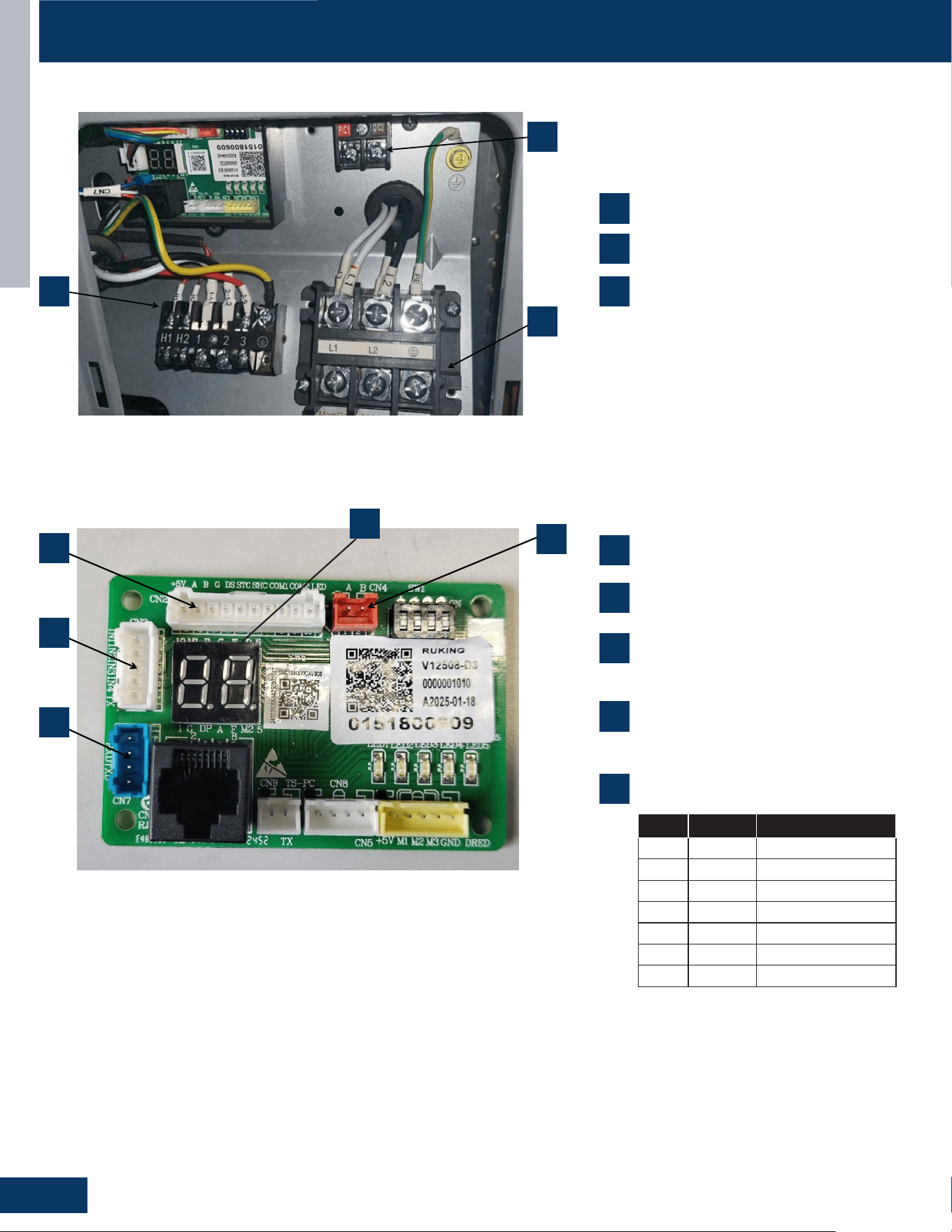
COMPONENTS
1. Mains Input terminal block
2. IDU connection terminal block
3. Centralized Controller terminal block
3
2
1
Light board: 0151800609
1. CN2 Communication terminal block
2. CN3 Communication terminal block
3. CN7 RJ45 communication terminal block
4. CN4 Centralized Controller communication terminal block
2
3
1
4
2
1
1
1
2
3
4
5
5
2
3
4
3
Light Board: 0151800609
1
2
3
Mains Input Terminal Block
IDU Connection Terminal Block
Centralized Controller Terminal Block
CN2: Communication Terminal Block
CN3: Communication Terminal Block
CN7: RJ45 Communication Terminal Block
CN4: Centralized Controller
Communication Terminal Block
Service Monitor Board Display
When the unit is operating normally, the
letters in the above table will be displayed
rst, followed by the compressor
frequency. In case of a fault, it displays the
fault code. For example: When in cooling
mode, it rst shows "Co" and then the
compressor frequency.
No. Name Name meaning
1 Co Cooling
2 He Heating
3 Fa Fan
4 rr Refrigerant recovery
5 oF Turn o
6 dE Dfrost
7 oI Oil return
OUTDOOR UNITS
B7
ENGLISH
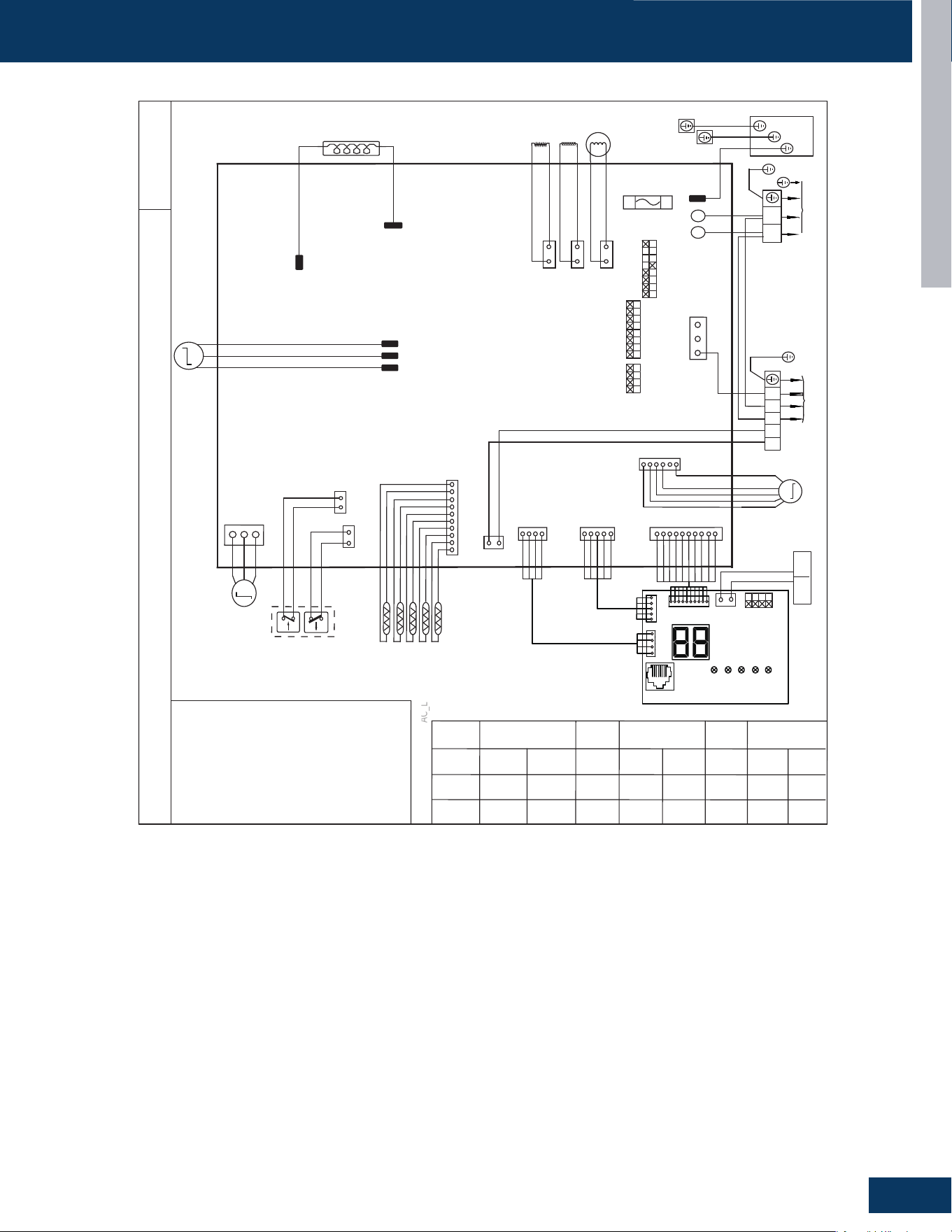
WIRING DIAGRAM
CIRCUIT DIAGRAM OF OUTDOOR UNIT
AC_L
0150578069
SW7
SW6
SW5-1
SW5-2
SW5-3
SW5-4
SW5-5
SW5-6
SW5-7
SW5-8
OFF
OFF
OFF
OFF
OFF
OFF
OFF
ON
ON
ON
ON
OFF
OFF
OFF
OFF
OFF
Tc:Condensing Temp.Sensor
Ts:Compressor Suction Temp.Sensor
Ta: Ambient Temp.Sensor
Td:Compressor Discharge Temp.Sensor
Te:Defrosting Temp.Sensor
4WAY:4 Way valve
B:black,BL:blue,GR:Gray,W:White,
R:red,Y/G:yellow/green,BR:Brown.
HPS/LPS:High/Low Pressure Switch
Reactor
CON1
CON2
CN10
CN12
CN11
U
V
W
R
B
W
COMPRESSOR
T30A 250V
FUSE1
SW5
ON
SW6
SW7
Y/G
W
B
L2
POWER SUPPLY
L1
Y/G
L1
L2
PE
CONTROL BOARD
M
DC FAN
MOTOR
W UV
CN29 W
COM1
COM3
COM2
CN2 W
W
B
R
H2
H1
1 32
Y/G
TO INDOOR UNIT
CN16 R
TC
TS
TA
TD
TE
CN21 BL
CN25
CN24
R
W
HPS LPS
CN1 R
M
E.E.V
CN8 B
CN9 G
CN7 W
4WAY
Base pan heater
Crankcase
SW1
CN15 W
CN14 W
CN13 W
LED1
LED2
LED3
LED4
LED5
CN3 W
CN7
CN6 RJ45
BL
CN2 W
CN4 R
SMG1
P/C1
Q/C2
ON
A
B
3036
24
CAPACITY
(kW)
ALL OFF
ALL OFF
R
BR
R
BR
GR
GR
A
B
3036
24
Y/G
Y/G
heater
M
SW1
ALL OFF
Note: CH: Crankcase heater. EH: Base pan heater
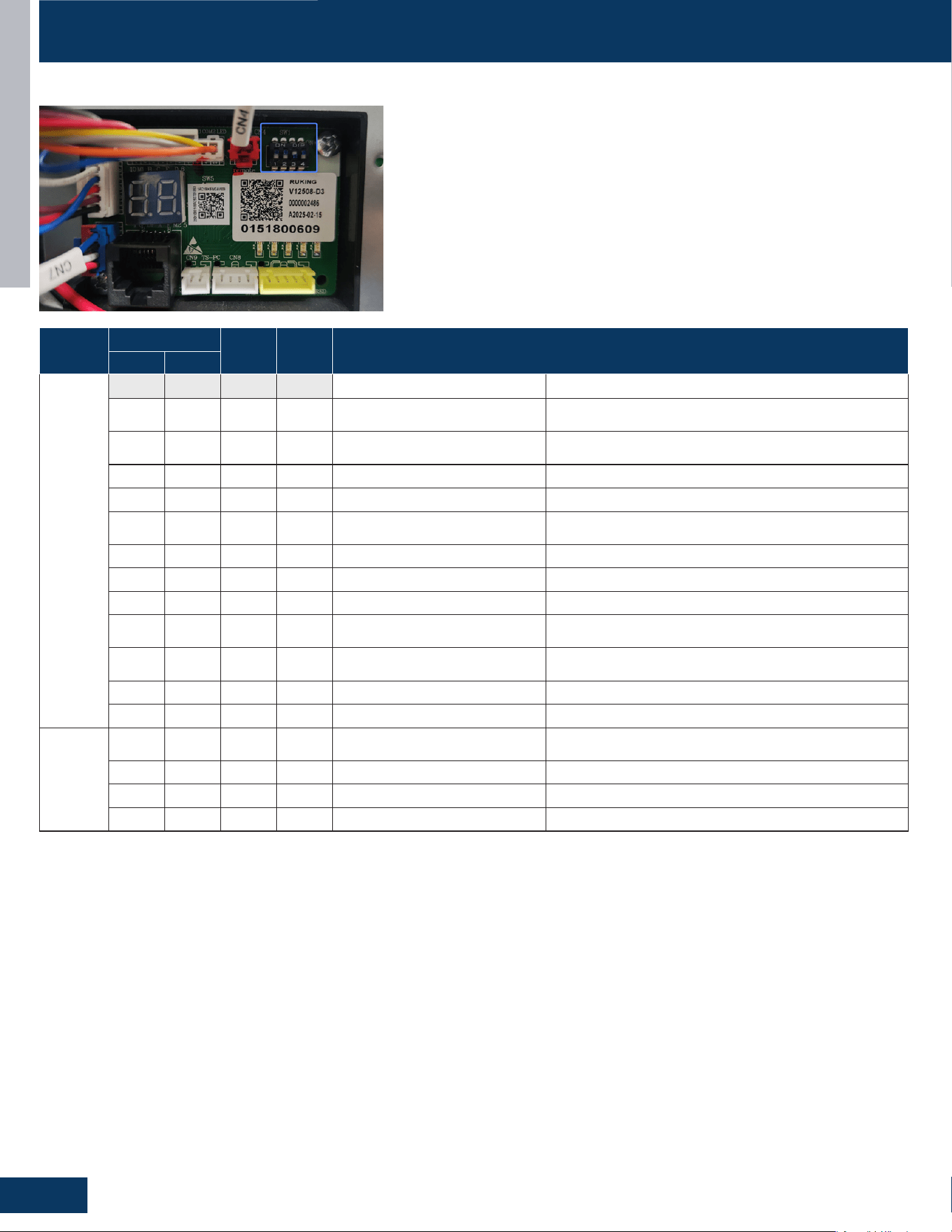
OUTDOOR UNITS
B8
ENGLISH
DIP SWITCH SETTINGS
SW1
Dehumidication
Heating Defrost
1 2
Operating
Mode
SW1-1 SW1-2 SW1-3 SW1-4 Cooling Heating
0 0 0 0 Standard Cooling
Standard heating+ordinary defrosting
(compatible with 24V and Strong electricity)
0 0 0 1 Standard Cooling
Standard heating+ordinary defrosting
(compatible with 24V and Strong electricity)
0 0 1 0 Standard Cooling Strong heating+ordinary defrosting (only eective at 24V)
0 0 1 1 Standard Cooling Strong heating+strong defrosting (only eective at 24V)
1 0 0 0 Dehumidication level 1
Standard heating+ordinary defrosting
(only eective at 24V)
1 0 0 1 Dehumidication level 1 Standard heating+strong defrosting (only eective at 24V)
1 0 1 0 Dehumidication level 1 Strong heating+ordinary defrosting (only eective at 24V)
1 0 1 1 Dehumidication level 1 Strong heating+strong defrosting (only eective at 24V)
0 1 0 0 Dehumidication level 2
Standard heating+ordinary defrosting
(only eective at 24V)
0 1 0 1 Dehumidication level 2 Standard heating+strong defrosting (only eective at 24V)
0 1 1 0 Dehumidication level 2 Strong heating+ordinary defrosting (only eective at 24V)
0 1 1 1 Dehumidication level 2 Strong heating+strong defrosting (only eective at 24V)
Force
Mode
1 1 0 0
Forced cooling
(Strong electricity, 24V universal)
1 1 0 1 Forced cooling
1 1 1 0 Forced heating
1 1 1 1 Refrigerant charging mode
1. SW4 performs manual defrosting from o to on (only heating is eective, exit conditions refer to normal defrosting, each time the dip switch is
turned from OFF to ON, it only enters once, and the next entry must meet the requirement of the dip switch being turned from OFF to ON. After
manual defrosting is completed, if the dip switch is still ON, it will enter strong defrosting
2.The DIP switch of the board is valid when the switch is powered on. (To prevent the conict between the combined DIP switch and the single
DIP switch, the combined DIP switch function is delayed for 10s.
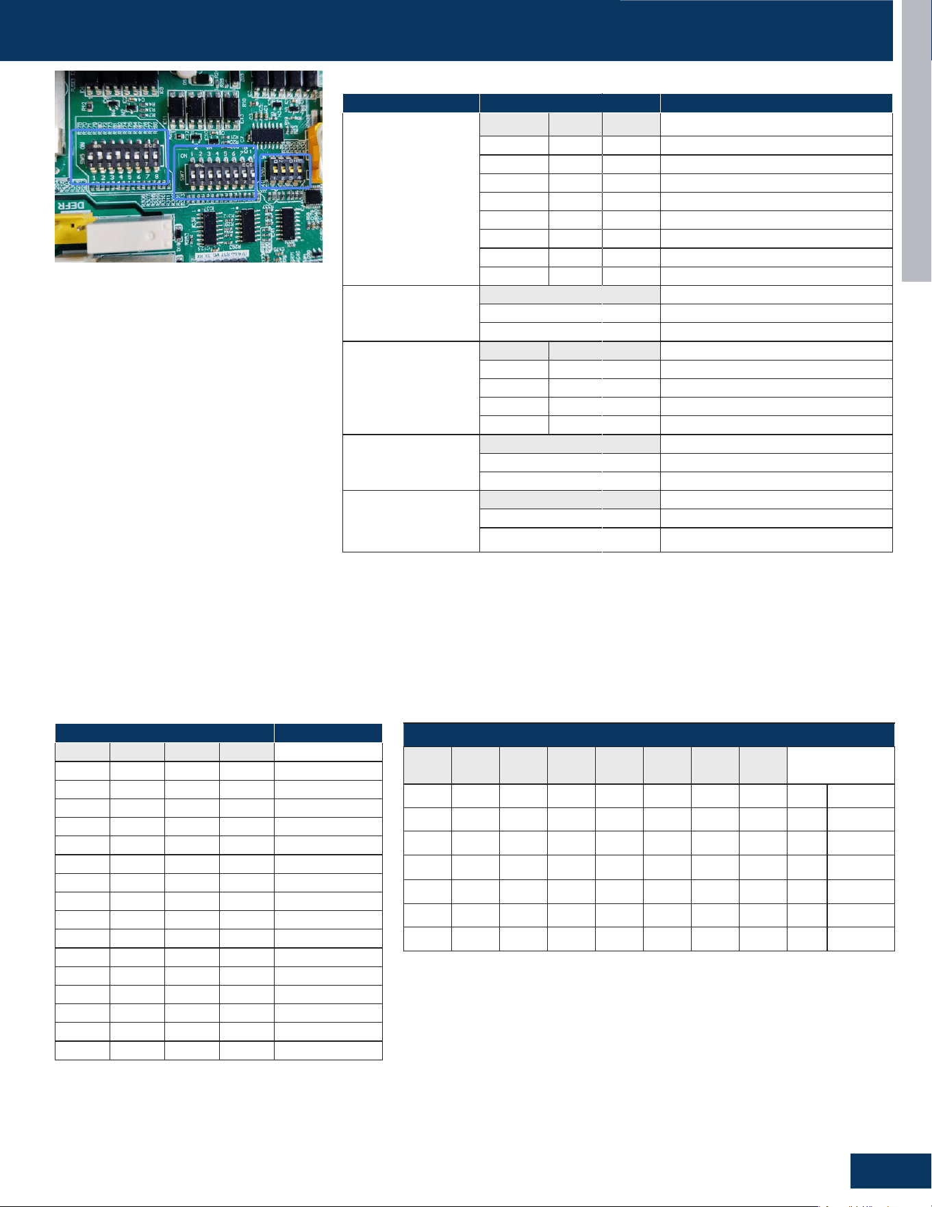
OUTDOOR UNITS
B9
ENGLISH
DIP SWITCH SETTINGS
SETTING ITEM SETTING DESCRIPTION
ODU HP
SW5-1 SW5-2 SW5-3
OFF OFF OFF Reserve
ON OFF OFF ODU 2HP (18KCapacity)
OFF ON OFF ODU 3HP (24K Capacity)
ON ON OFF ODU 3.2HP (30K Capacity)
OFF OFF ON ODU 4HP (36K Capacity)
ON OFF ON ODU 4.5HP (42K Capacity)
OFF ON ON ODU 5HP (48K Capacity)
ON ON ON ODU6HP (60K Capacity)
Indoor and Outdoor
Communication Mode
SW5-4
OFF 24V communication mode (AHU)
ON Strong electric communication
Reserve
SW5-5 SW5-6
OFF OFF Reserve
OFF ON Reserve
ON OFF Reserve
ON ON Reserve
24V Signal Truth Table
Selection (O or B)
SW5-7
OFF Reserve
ON Reserve
Central Control and
BMS Control
SW5-8
OFF Central control
ON BMS control
Function dip switch selection instructions:
The change in dip switch status can only take eect after the chip is reset after power o.
The corresponding dual fan (PCB 0151801003A) for ODUs with a horsepower greater than or
equal to 4.5HP, and the corresponding single fan (PCB 0151801031/A) for units below 4.5HP.
Note: Strong electric communication mode: for the test of 24V ODU and IDU communication 24V
energy eciency test IDU: 24v communication IDU, such as AHU, A-COIL
SETTING DESCRIPTION
SW6-1 SW6-2 SW6-3 SW6-4
OFF OFF OFF OFF Reserve
OFF OFF OFF ON Reserve
OFF OFF ON OFF Reserve
OFF OFF ON ON Reserve
OFF ON OFF OFF Reserve
OFF ON OFF ON Reserve
OFF ON ON OFF Reserve
OFF ON ON ON Reserve
ON OFF OFF OFF Reserve
ON OFF OFF ON Reserve
ON OFF ON OFF Reserve
ON OFF ON ON Reserve
ON ON OFF OFF Reserve
ON ON OFF ON Reserve
ON ON ON OFF Reserve
ON ON ON ON
Reserve
Function dip switch selection instructions:
The power-o setting for dip switch is valid.
SW5, SW6, SW7
SW5-1 - SW5-8
SW6-1 - SW6-7 SW7-1 - SW7-8
When all the DIP switches of SW7 are set to 0, even if the centralized controller is
connected, the centralized controller will be in a failed state. Only when any DIP
switch of SW7 is set to a non-0 value, the centralized collector can be normally
enabled.
In addition, when connecting multiple outdoorl units, it is only necessary to ensure
that the DIP switch settings of each outdoorl unit are dierent from each other.
ADDRESS OF CENTRALIZED CONTROLLER
SW7-1 SW7-2 SW7-3 SW7-4 SW7-5 SW7-6 SW7-7 SW7-8
Function
Description
ON OFF OFF OFF OFF OFF OFF 0*01 1000000*
OFF ON OFF OFF OFF OFF OFF 0*02 0100000*
ON ON OFF OFF OFF OFF OFF 0*03 1100000*
... ... ... ... ... ... ... ... ...
ON OFF ON ON ON ON ON 125 1011111*
OFF ON ON ON ON ON ON 126 0111111*
ON ON ON ON ON ON ON 127 1111111*
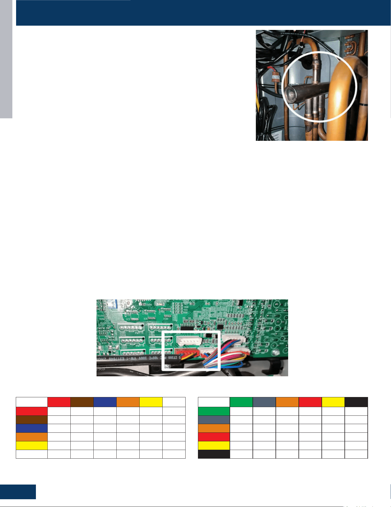
OUTDOOR UNITS
B10
ENGLISH
SERVICE PROCEDURES
4-Way Valve
The 4-way valve will control the direction of hot gas discharge via an internal slide assembly.
The valve has a line voltage solenoid that is energized in heat mode. The solenoid will direct
the internal slide to send the hot gas to the indoor coil. During cooling mode de-energized
operation, the internal slide will direct compressor hot gas to the outdoor coil.
4-way valves may have a failure of the electrical solenoid that prevents the valve from shifting,
or they may become stuck due to debris lodging inside the valve body. If the valve fails to direct
the hot gas in the proper direction, temperature sensors within the outdoor unit will detect the
problem and generate an error code.
If the valve fails to shift the hot gas to the proper coil, or it only partially shifts,
perform the following:
1. Check for correct refrigerant charge, and that all other operating parameters have been met.
2. In the heating mode, the solenoid will shift after a short time delay. Check for line voltage to
the solenoid coil.
3. If the valve has voltage but fails to shift the hot gas to the indoor coil, shut the system down and unplug the 4-way valve from the PCB plug.
4. Use an ohmmeter to check continuity through the solenoid coil. If the coil resistance does not match the chart in this manual, or if a winding
shows open or shorted, the solenoid coil will have to be replaced.
5. If the coil resistance is within the tolerance, use a magnet along the valve body to determine the location of the piston. If one end of the
piston is against the end of the valve body, it is stuck and the valve must be replaced.
6. Partial shifting of the valve can be detected by measuring the temperature of the suction gas where it enters the reversing valve and then
comparing that temperature to the temperature of the suction gas exiting the 4-way valve. There should be no more than 3F dierence.
Excessive temperature rise through the suction gas path is an indication of a stuck piston. If the piston will not become free by switching
from heating to cooling several times, a slight tapping on the valve body, or by using a powerful magnet, the valve will require replacement.
Electronic Expansion Valve (EEV)
1. Check to see if the Electronic expansion valve (EEV) connector is correctly and rmly inserted in the PCB.
2. Turn the power o and back on again,
3. Check to see whether the EEV have a reposition sound. This sound will start after approx 2 min. If the EEV doesn’t have noise,
please disconnect the connector and check the resistance (refer to resistance tables below).
4. If the resistance is OK, The PCB may be at fault.
24K EEV (6-pin, 6 wire)
Red Brown Blue Orange Yellow White
Red
- 0L 45 0L 45 0L
Brown
- - 0L 45 0L 45
Blue
- - - 90 0L 0L
Orange
- - - - 0L 90
Yellow
- - - - - 0L
White
- - - - - -
3036K EEV (6-pin, 6 wire)
Green Gray Orange Red Yellow Black
Green
- 0L 45 0L 45 0L
Gray
- - 0L 45 0L 45
Orange
- - - 90 0L 0L
Red
- - - - 0L 90
Yellow
- - - - - 0L
Black
- - - - - -
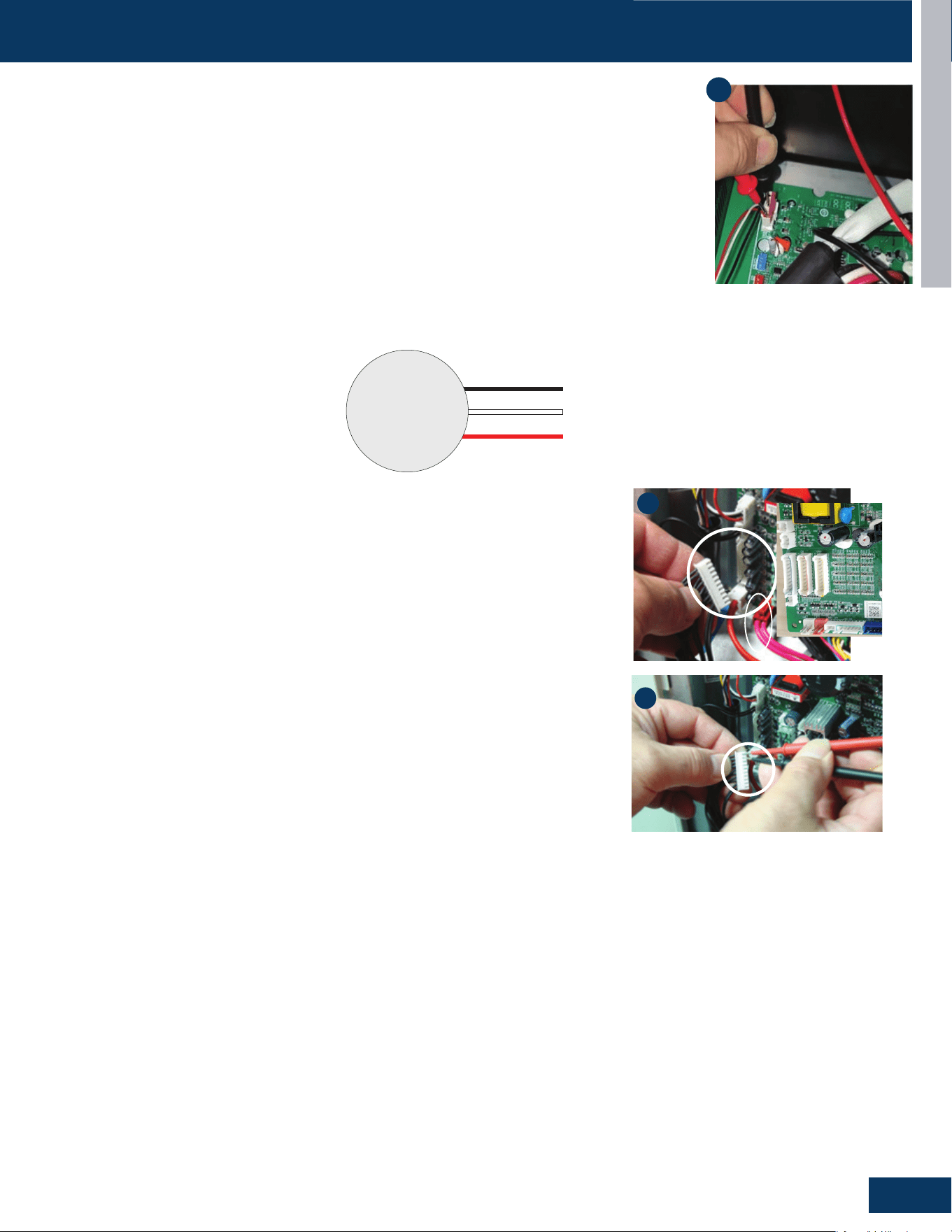
OUTDOOR UNITS
B11
ENGLISH
SERVICE PROCEDURES
Outdoor Fan Motor
Check that the wiring and plug connections are in good condition.
If the outdoor unit fan motor does not run, or the Service Monitor Board indicates an error code of 09,
check the following voltages at connector CN11 on the outdoor unit PCB. Set the meter to read DC volts
with a minimum voltage range of 350 volts. All voltage values are approximate. Initiate forced cooling.
1. DC voltage between the Red and Black wires should read 310 - 334VDC. This is the main voltage for
powering the fan motor.
2. DC voltage between the White and Black wires should read 310-334VDC. This is the main voltage for
powering the fan motor.
3. DC voltage between the Red and White wires should read 310-334VDC. This is the main voltage for
powering the fan motor.
If the outdoor fan initially runs, increases speed then stops, and the Service Monitor Board indicates an
error code of 09, the feedback circuit is not functioning. Check that the wiring and plug connections are in
good condition.
1
DC
Motor
310 VDC
310 VDC
Red
Black
White
Temperature Sensor
The temperature sensors are negative coecient thermistors, in which resistance decreases
as temperature rises. Should the sensors fail, the PCB will generate an appropriate error
code.
To check the calibration of the sensors:
1. Shut o power to the outdoor unit.
2. Disconnect the sensor at the circuit board plug.
3. Measure the temperature of the air surrounding the sensor.
4. Measure the electrical resistance of the sensor using needle probes. Do not force
standard probes into the sensor plug.
5. Compare the measured resistance of the sensor against the resistance/temperature
specications (See chart in reference section)
6. If the sensor resistance is outside of the specication tolerances shown on the
resistance/temperature table, replace the sensor.
2
4
1G24ED2BEA: 19.7Ω±7%Ω
1G3036ED2BEA: 20.5Ω±10%Ω
Base Pan Heater
1. Check whether there is voltage at both ends of the terminal. If no,
it needs to replace the PCB.
2. If there’s nothing wrong with the voltage signal, check the
resistance of pan heater. If the value is abnormal, it needs to
replace the pan heater.
Compressor Heater Band
1. Check whether there is voltage at both ends of the terminal. If no,
it needs to replace the PCB.
2. If there’s nothing wrong with the voltage signal, check the
resistance of compressor heater band. If the value is abnormal, it
needs to replace the pan heater.
[This page intentionally left blank.]

HIGHWALL INDOOR UNITS
C1
ENGLISH
HIGHWALL INDOOR UNITS
COMPONENTS .......................................................................................................................................................................C2
Indoor Component Identication ..........................................................................................................................................C2
Terminal Block .........................................................................................................................................................................C4
Display .....................................................................................................................................................................................C4
Ambient Temperature Sensor ...............................................................................................................................................C4
Piping Temperature Sensor ...................................................................................................................................................C4
Louver Stepper Motor ............................................................................................................................................................C5
Fan Motor ................................................................................................................................................................................C5
Emergency Button ..................................................................................................................................................................C5
Indoor Unit Control Board ......................................................................................................................................................C6
WIRING DIAGRAM ................................................................................................................................................................... C7
DIP SWITCH SETTINGS
..........................................................................................................................................................C8
TABLE OF CONTENTS
GS24WP2BEA
GS30WB2BEA
GS36WB2BEA
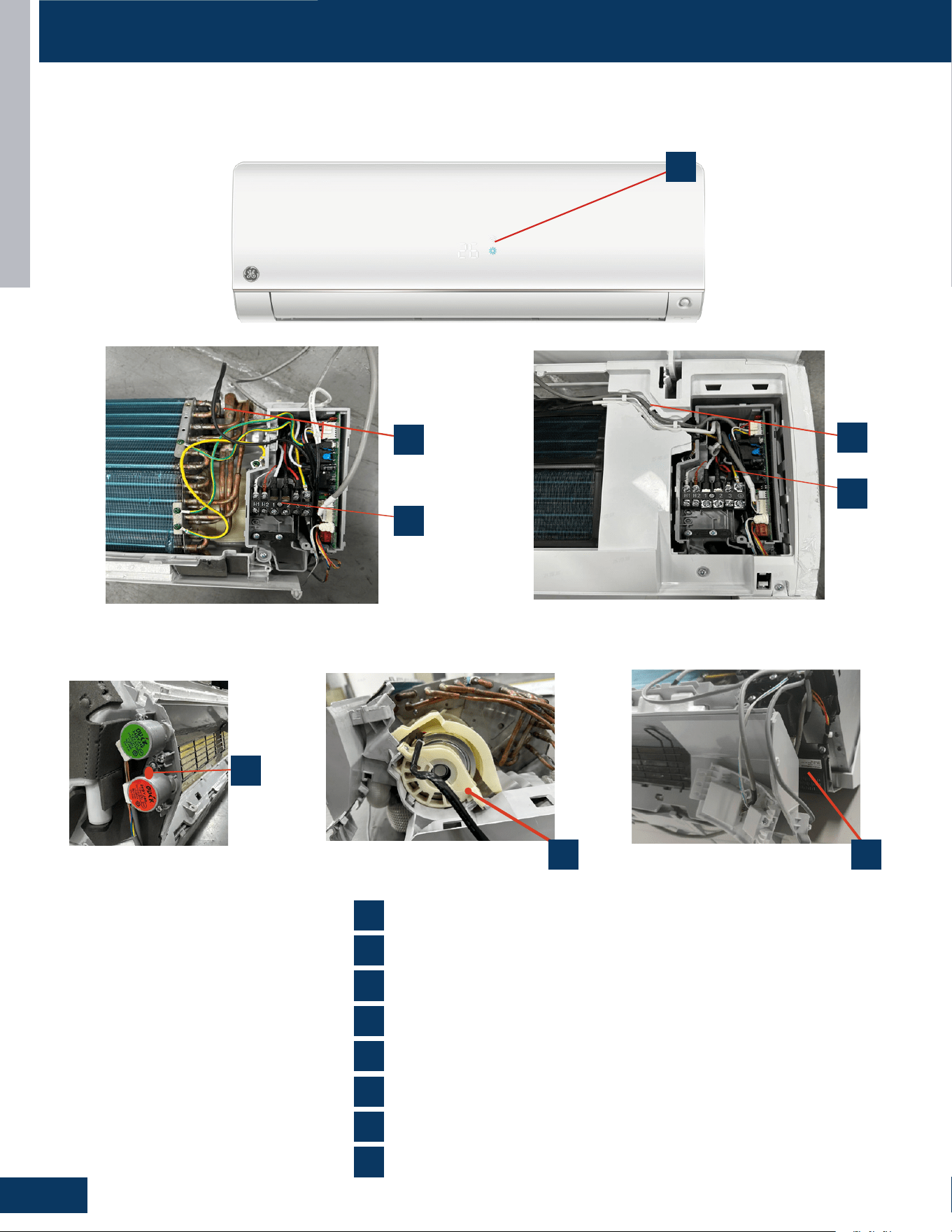
HIGHWALL INDOOR UNITS
C2
ENGLISH
Indoor Component Identication
COMPONENTS
INDOOR UNITS
ENGLISH
,QGRRU&RPSRQHQW,GHQWLƭFDWLRQ
COMPONENTS
1
2
3
4
5
6
7
6
2
5
4
3
7
1
8
Ambient Temperature Sensor
Display Panel
Fan Motor
Louver Motors
Power Control Board(PCB)
Piping Temperature Sensor
Terminal Block
8
R454B Leakage sensor
QS24WP2BEA
INDOOR UNITS
ENGLISH
,QGRRU&RPSRQHQW,GHQWLƭFDWLRQ
COMPONENTS
1
2
3
4
5
6
7
6
2
5
4
3
7
1
8
Ambient Temperature Sensor
Display Panel
Fan Motor
Louver Motors
Power Control Board(PCB)
Piping Temperature Sensor
Terminal Block
8
R454B Leakage sensor
QS24WP2BEA
INDOOR UNITS
ENGLISH
,QGRRU&RPSRQHQW,GHQWLƭFDWLRQ
COMPONENTS
1
2
3
4
5
6
7
6
2
5
4
3
7
1
8
Ambient Temperature Sensor
Display Panel
Fan Motor
Louver Motors
Power Control Board(PCB)
Piping Temperature Sensor
Terminal Block
8
R454B Leakage sensor
QS24WP2BEA
INDOOR UNITS
ENGLISH
,QGRRU&RPSRQHQW,GHQWLƭFDWLRQ
COMPONENTS
1
2
3
4
5
6
7
6
2
5
4
3
7
1
8
Ambient Temperature Sensor
Display Panel
Fan Motor
Louver Motors
Power Control Board(PCB)
Piping Temperature Sensor
Terminal Block
8
R454B Leakage sensor
QS24WP2BEA
INDOOR UNITS
ENGLISH
,QGRRU&RPSRQHQW,GHQWLƭFDWLRQ
COMPONENTS
1
2
3
4
5
6
7
6
2
5
4
3
7
1
8
Ambient Temperature Sensor
Display Panel
Fan Motor
Louver Motors
Power Control Board(PCB)
Piping Temperature Sensor
Terminal Block
8
R454B Leakage sensor
QS24WP2BEA
GS24WP2BEA
2
6
7
1
5
83
4
1
4
2
5
7
3
6
8
Ambient Temperature Sensor
Display Panel
Fan Motor
Louver Motors
Power Control Board(PCB)
Piping Temperature Sensor
Terminal Block
R454B Leakage Sensor
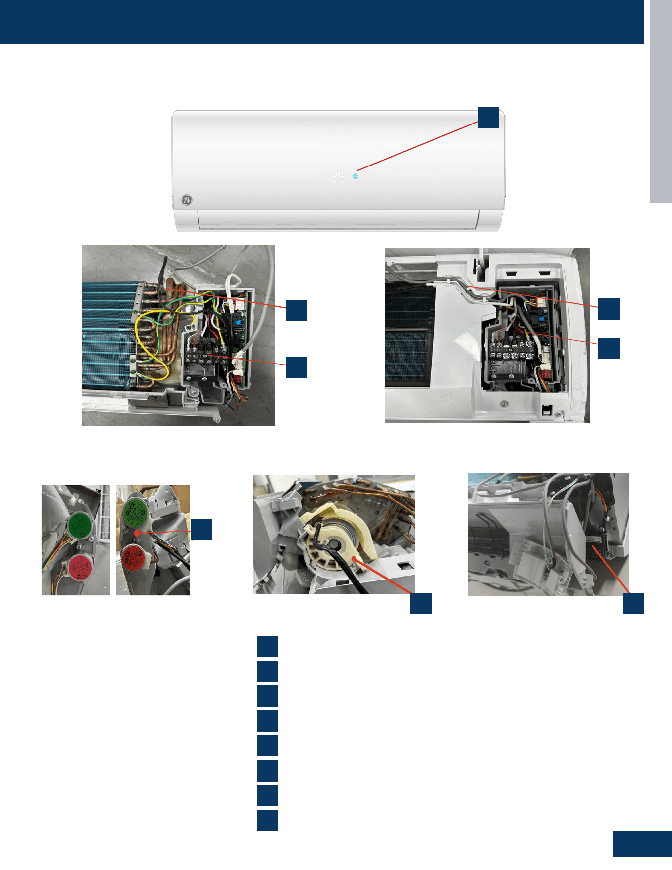
HIGHWALL INDOOR UNITS
C3
ENGLISH
COMPONENTSCOMPONENTS
INDOOR UNITS
ENGLISH
,QGRRU&RPSRQHQW,GHQWLƭFDWLRQ
COMPONENTS
1
2
3
4
5
6
7
6
2
5
4
3
7
1
8
Ambient Temperature Sensor
Display Panel
Fan Motor
Louver Motors
Power Control Board(PCB)
Piping Temperature Sensor
Terminal Block
8
R454B Leakage sensor
QS24WP2BEA
INDOOR UNITS
ENGLISH
,QGRRU&RPSRQHQW,GHQWLƭFDWLRQ
COMPONENTS
1
2
3
4
5
6
7
6
2
5
4
3
7
1
8
Ambient Temperature Sensor
Display Panel
Fan Motor
Louver Motors
Power Control Board(PCB)
Piping Temperature Sensor
Terminal Block
8
R454B Leakage sensor
QS24WP2BEA
INDOOR UNITS
ENGLISH
,QGRRU&RPSRQHQW,GHQWLƭFDWLRQ
COMPONENTS
1
2
3
4
5
6
7
6
2
5
4
3
7
1
8
Ambient Temperature Sensor
Display Panel
Fan Motor
Louver Motors
Power Control Board(PCB)
Piping Temperature Sensor
Terminal Block
8
R454B Leakage sensor
QS24WP2BEA
INDOOR UNITS
ENGLISH
,QGRRU&RPSRQHQW,GHQWLƭFDWLRQ
COMPONENTS
1
2
3
4
5
6
7
6
2
5
4
3
7
1
8
Ambient Temperature Sensor
Display Panel
Fan Motor
Louver Motors
Power Control Board(PCB)
Piping Temperature Sensor
Terminal Block
8
R454B Leakage sensor
QS24WP2BEA
GS30WB2BEA, GS36WB2BEA
2
6
7
1
5
83
4
1
4
2
5
7
3
6
8
Ambient Temperature Sensor
Display Panel
Fan Motor
Louver Motors
Power Control Board(PCB)
Piping Temperature Sensor
Terminal Block
R454B Leakage Sensor
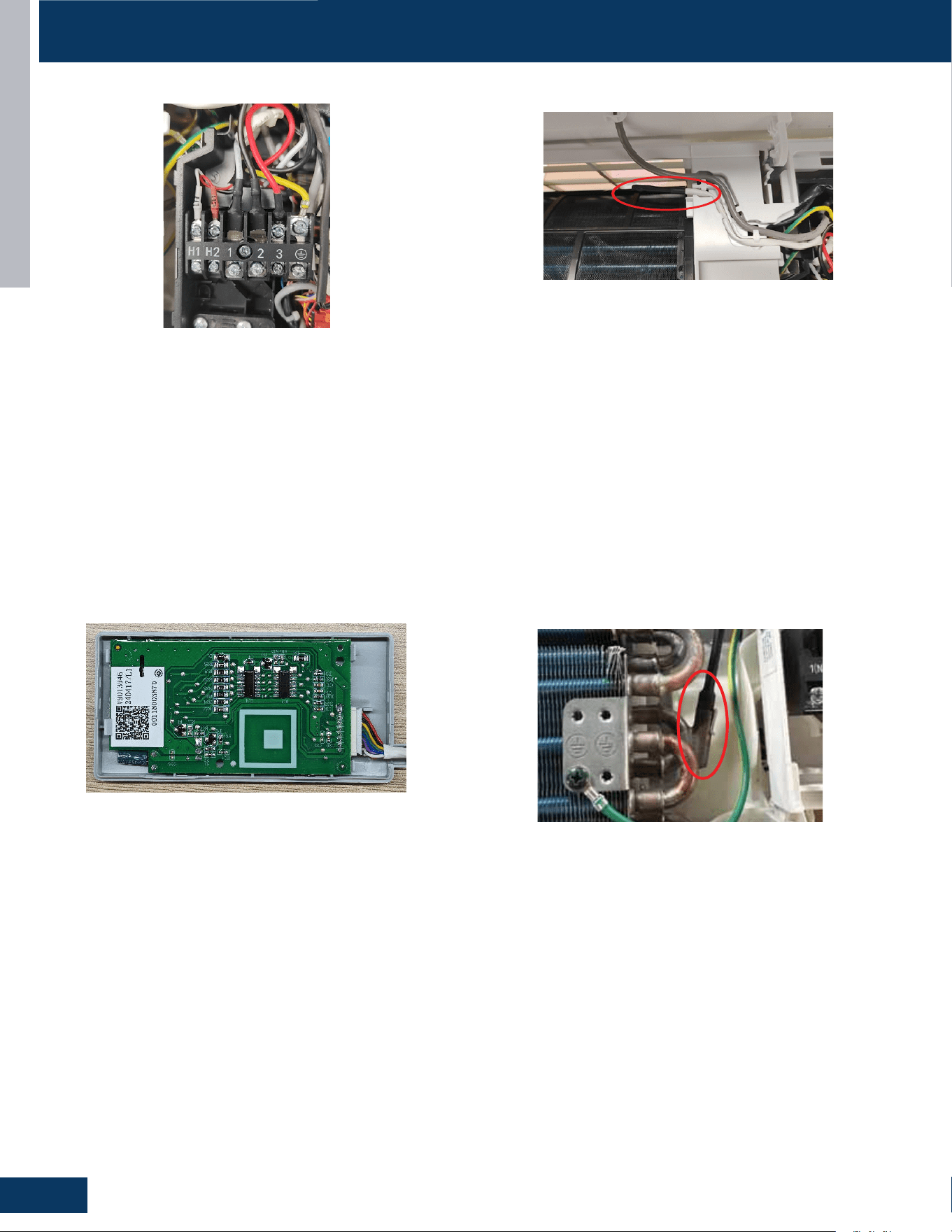
HIGHWALL INDOOR UNITS
C4
ENGLISH
Terminal Block
Ambient Temperature Sensor
The unit terminal block receives electrical power from the outdoor
unit. There are 4 connections for electrical wires. Terminals 1 and 2
are connected to terminals 1 and 2 of the outdoor unit. This wiring
supplies power to the indoor unit.
Terminal 3 is a communication wire. The indoor unit sends indoor air
temperature, coil temperature and temperature setpoint information
to the outdoor unit on this wire. If a splice or break in this wire is
present, the indoor unit will not be able to communicate with the
outdoor unit. The ERROR CODE will be an E7.
The Ambient (room) Temperature Sensor is a negative coecient
thermistor that will decrease in resistance with increases in room air
temperature. The sensor is located on a clip mounted in the return air
stream.
The sensor connects to the control board at Plug CN-6.
Piping Temperature Sensor
The Piping Temperature Sensor is a negative coecient thermistor
that will decrease in resistance with increases in coil temperature.
The sensor is located in a socket soldered to the surface of the
indoor coil.
This sensor will monitor the temperature of the indoor coil in both
cooling and heating modes of operation. Should abnormally cold or
hot coil temperature be detected by this sensor, the system will take
steps to correct the condition or report an ERROR CODE.
The sensor connects to the control board at Plug CN-6.
Display
The indoor display has an infrared communication circuit that
receives The indoor display has an infrared communication
circuit that receives operating commands from the remote
control. This display will indicate operating modes, error
codes, indoor air temperature, timer status, and power
status.
The display board connects to the control board at Plug CN-7.
COMPONENTS
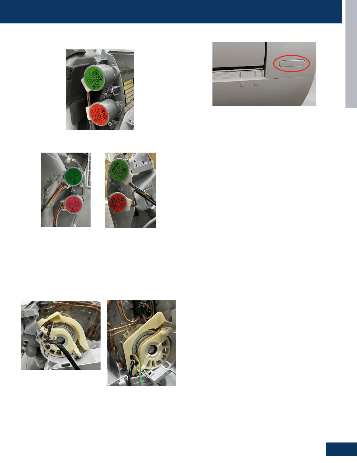
HIGHWALL INDOOR UNITS
C5
ENGLISH
Louver Stepper Motor
Fan Motor
Emergency Button
The Fan Motor is a variable speed motor. Fan speed will vary
depending upon the temperature variation from set point, or can be
set with the remote control to maintain a single set speed.
The Fan Motor is connected to the indoor control board via PLUG
CN-9.
If the remote control is non-functional, the Emergency Button can be
used. 73 -78
O
F will be maintained, until commands are received via
the remote control.
The motor moves the louver side to side depending upon selections
made at the remote control.
These motors are connected at CN-5.
COMPONENTSCOMPONENTS
GS24WP2BEA
GS24WP2BEA
GS30WB2BEA, GS36WB2BEA
GS30WB2BEA
GS36WB2BEA
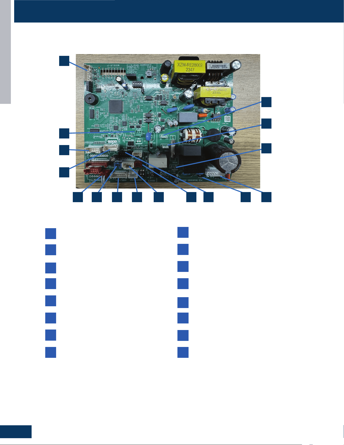
HIGHWALL INDOOR UNITS
C6
ENGLISH
COMPONENTS
Indoor Unit Control Board
13
8 11 49
14
105 2
12
3
16
67
15
1
2
CN27: Connector for GND
4
CN9: Connector for fan motor
8
CN1: Connector for non-polar wire controller
10
CN6: Connector for the temperature sensor
12
CN35: Connector for the WIFI
CN21: 208/230 AC power from terminal block
connections 1(L1)
1
CN7: Connector for the display board
7
CN14: Connector for emergency switch
5
CN3: Connector for the leakage sensor
11
CN23: Communication connection between the
indoor board and the outdoor board
3
CN51: Connector for the room cord
9
CN36: Connector for the centralized controller
6
CN5: Connector for the up-down step motor
13
14
CN2: Connector for the OTA
15
16
CN38: Connector for the RJ45
CN17: 208/230 AC power from terminal block
connections 2(L2)
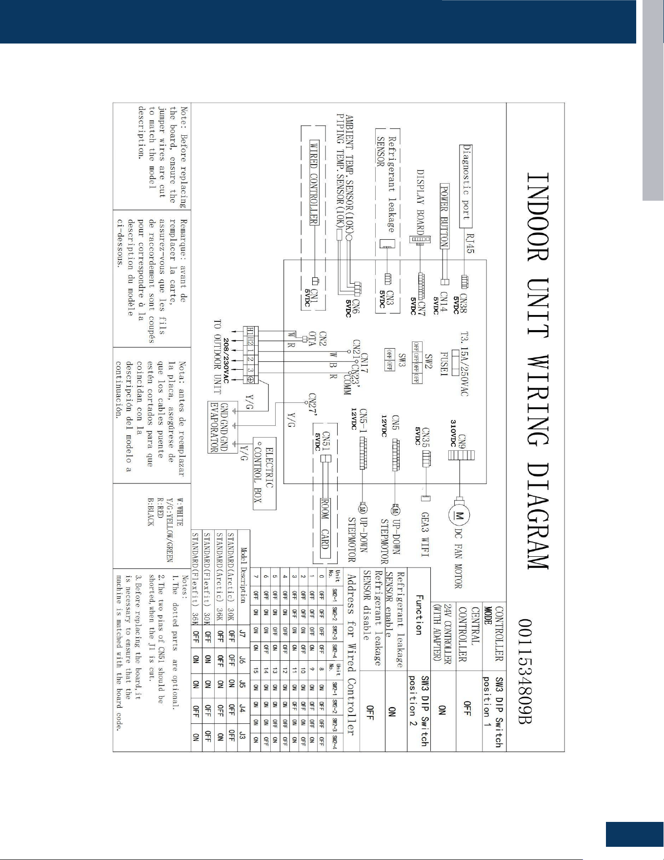
HIGHWALL INDOOR UNITS
C7
ENGLISH
WIRING DIAGRAM
INTRODUCTION
PAGE 4
ENGLISH
IDU Wiring Diagram
QS24WP2BEA、QS30WP2BEA、QS36WP2BEA
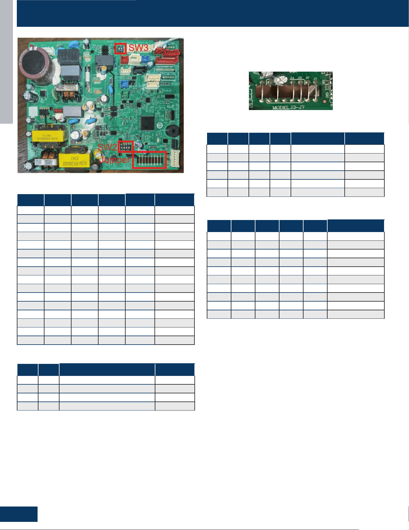
HIGHWALL INDOOR UNITS
C8
ENGLISH
DIP SWITCH & JUMPER SETTINGS
SW2-1 SW2-2 SW2-3 SW2-4 Setting Description
OFF OFF OFF OFF 0# Default
OFF OFF OFF ON 1#
OFF OFF ON OFF 2#
OFF OFF ON ON 3#
OFF ON OFF OFF 4#
OFF ON OFF ON 5#
OFF ON ON OFF 6#
OFF ON ON ON 7#
ON OFF OFF OFF 8#
ON OFF OFF ON 9#
ON OFF ON OFF 10#
ON OFF ON ON 11#
ON ON OFF OFF 12#
ON ON OFF ON 13#
ON ON ON OFF 14#
ON ON ON ON 15#
DIP SW2: Wire Controller Address
SW3-1 SW3-2 Setting Description
OFF -- Central Controller Default
ON -- 24v Controller
-- OFF Refrigerant Leak Detector Disable
-- ON Refrigerant Leak Detector Enable Default
DIP SW3
J1 J2 J8 J4 Setting Description
OFF -- -- -- Room Card Valid
ON -- -- -- Room Card Invalid Default
-- OFF -- -- Sub
-- ON -- -- Main Default
-- -- OFF -- WiFi 2.18 Protocol
-- -- ON -- WiFi GE3 Protocol Default
Jumpers J1, J2, J8
J7 J6 J5 J4 J3 Setting
OFF OFF OFF ON ON Endure 24K
OFF OFF ON OFF OFF Reserved
OFF OFF ON OFF ON Reserved
OFF ON ON ON OFF Reserved
OFF ON ON ON ON Reserved
ON OFF OFF OFF OFF Reserved
ON OFF OFF OFF ON Reserved
ON OFF OFF ON OFF Reserved
-- -- -- -- -- Reserved
ON ON ON ON ON Reserved
Jumpers J3-J7
The PCB has a set of jumper wires that must be checked when
replacing the PCB. The replacement PCB is shipped with no jumper
wires cut.

CASSETTE
D1
ENGLISH
CASSETTE
TABLE OF CONTENTS
US24LB2BEA
US30LB2BEA
US36LB2BEA
COMPONENTS .......................................................................................................................................................................D2
Indoor Component Identication ......................................................................................................................................... D2
Terminal Block ........................................................................................................................................................................ D3
Blower Motor.......................................................................................................................................................................... D3
Display ................................................................................................................................................................................. D3
Blower Assembly ................................................................................................................................................................... D3
Louver Motors ........................................................................................................................................................................ D3
Piping Temperature Sensor .................................................................................................................................................. D3
Ambient Temperature Sensor .............................................................................................................................................. D3
Control Board ......................................................................................................................................................................... D4
Condensate Pump & Float Switch ........................................................................................................................................ D4
WiFi........ ................................................................................................................................................................................. D4
Refrigerant Leakage Detector .............................................................................................................................................. D4
PCB Overview ........................................................................................................................................................................ D5
WIRING DIAGRAM ................................................................................................................................................................... D6
OUTDOOR/INDOOR WIRING CONNECTIONS
........................................................................................................................D7
DIP SWITCH & JUMPER SETTINGS
.........................................................................................................................................D8
SERVICE PROCEDURES
..........................................................................................................................................................D9
Resistance Values .................................................................................................................................................................. D9
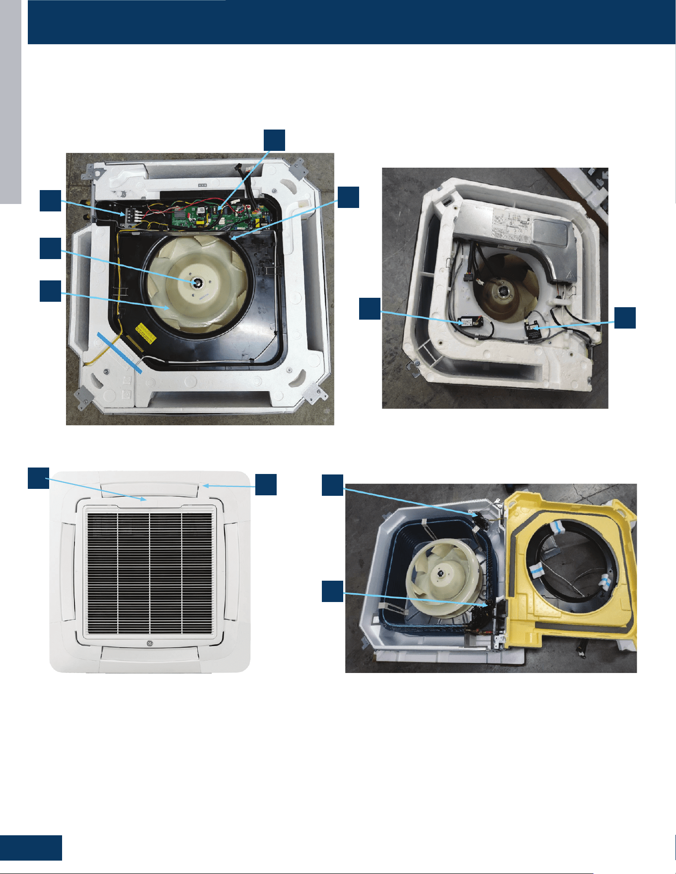
CASSETTE
D2
ENGLISH
COMPONENTS
US09CB2BEA / US12CB2BEA / US18CB2BEA / US24LB2BEA / US30LB2BEA / US36LB2BEA
1
2
4
8
7
10
11
9
6
Indoor Component Identication
3
5
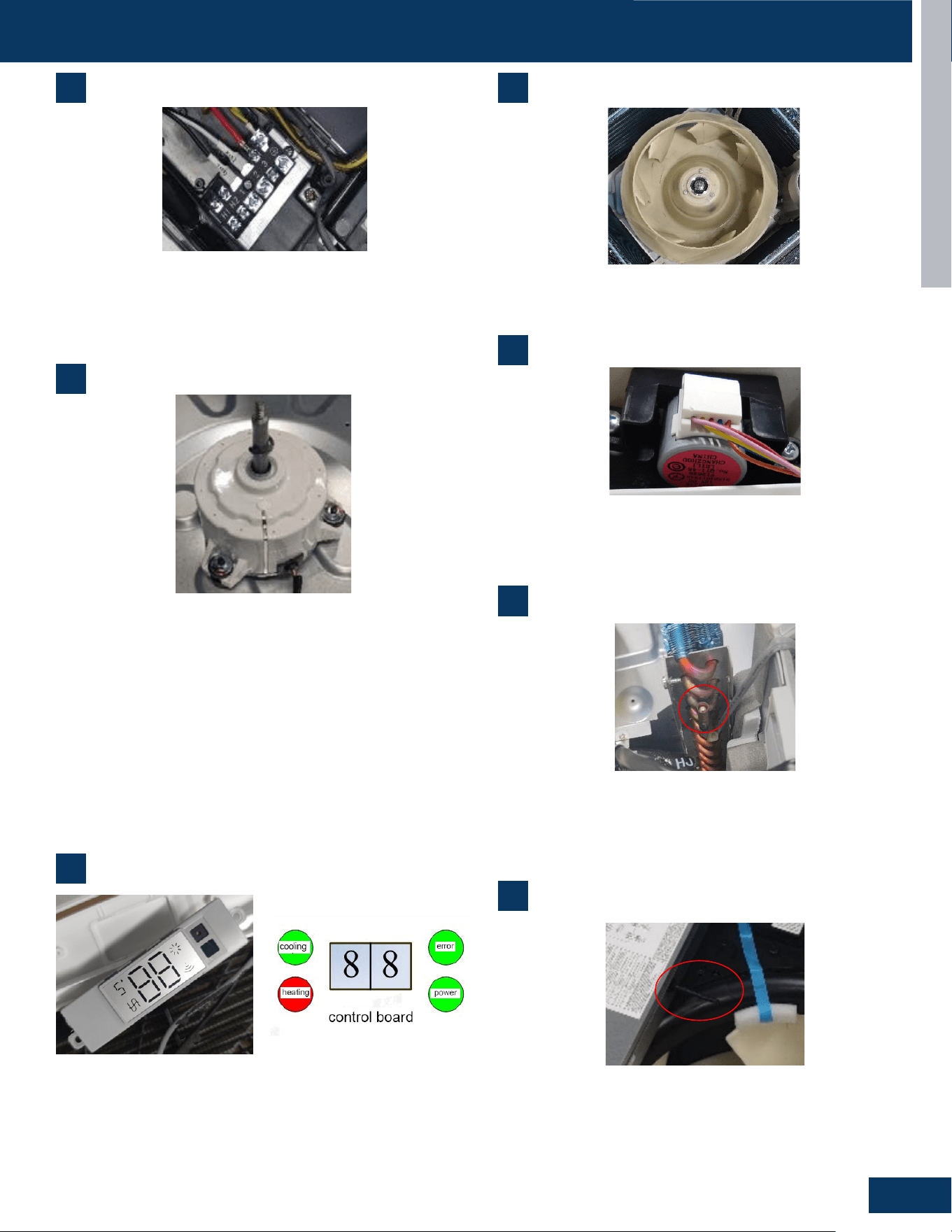
CASSETTE
D3
ENGLISH
COMPONENTS
4
5
Blower Assembly
Louver Motors
1
Terminal Block
1. Terminal Block
Power to operate the indoor unit comes from the electrical line voltage terminal block at
the outdoor unit. The wiring includes 4 wires, 1, 2, 3 and ground. Wires 1 and 3 complete
the data path. These wires should always
be
14 gauge AWG stranded cooper,
non
-
shielded
type wire. Splices in wires 1 or 3 may cause communication errors.
6
9
Power to operate the indoor unit comes from the electrical line
voltage terminal block at the outdoor unit. The wiring includes
4 wires, 1, 2, 3 and ground. Wires 1 and 3 complete the data
path. These wires should always be 14 gauge AWG stranded
cooper, nonshielded type wire. Splices in wires 1 or 3 may cause
communication errors.
The blower assembly consists of a plastic blower wheel that is
connected to a PSC indoor blower motor. A set screw holds the
blower wheel to the blower motor.
The louver motors are stepper type motors that move the louvers
up/down. The motors are controlled by pulsed voltage that cannot
be measured. If the louver does not move when it should, check for a
bind in the louvers.
2
Blower Motor
The indoor unit features a multi speed blower motor that will
change speed to match the capacity demand from the outdoor unit.
Separate motors located in the indoor unit control the operation
of the motorized louvers. All of the louver motors are controlled via
commands received from the remote control. The blower motor is
controlled by both the remote control and by commands from the
outdoor unit ECU.The indoor blower motor is a Multi Speed Fan Motor
that is connected to the indoor unit control board. The wiring from
the motor to indoor board consists of 4 wires connected to pins
common, low , medium and high speeds. During normal operation,
the indoor control board will energize the indoor blower motor and
request proper speed. The motor has a run capacitor that is located
in the Cassette unit’ s control box. The run capacitor connects to the
motor via two orange wires. This capacitor is eld replaceable.
2. Motor Blower
The indoor unit features a multi speed blower motor that will change speed to match
the capacity demand from the outdoor unit. Separate motors located in the indoor unit
control the operation of the motorized louvers. All of the louver motors are controlled
via commands received from the remote control. The blower motor is controlled by both
the remote control and by commands from the outdoor unit ECU.
The indoor
blower motor is a Multi Speed Fan Motor that is connected to the indoor unit control
board. The wiring from the motor to indoor board consists of 4 wires connected to pins
common, low , medium and high speeds. During normal operation, the indoor control
board will energize the indoor blower motor and request proper speed. The motor has
a run capacitor that is located in the Cassette unit
’
s control box. The run capacitor
connects to the motor via two orange wires. This capacitor is field replaceable.
The indoor unit has a display that communicates system mode. The indoor unit does not
display temperatures or diagnostic codes. When a wired controller is used, this
information is displayed on the wired controller. It is recommended to use a wired
controller with the cassette unit. When servicing a diagnostic error, ALWAYS refer to the
3. Display
outdoor unit code to make diagnostic decision
3
Display
The indoor unit has a display that communicates system mode.
The indoor unit does not display temperatures or diagnostic codes.
When a wired controller is used, this information is displayed on the
wired controller. It is recommended to use a wired controller with the
cassette unit. When servicing a diagnostic error, ALWAYS refer to the
outdoor unit code to make diagnostic decision
2. Motor Blower
The indoor unit features a multi speed blower motor that will change speed to match
the capacity demand from the outdoor unit. Separate motors located in the indoor unit
control the operation of the motorized louvers. All of the louver motors are controlled
via commands received from the remote control. The blower motor is controlled by both
the remote control and by commands from the outdoor unit ECU.
The indoor
blower motor is a Multi Speed Fan Motor that is connected to the indoor unit control
board. The wiring from the motor to indoor board consists of 4 wires connected to pins
common, low , medium and high speeds. During normal operation, the indoor control
board will energize the indoor blower motor and request proper speed. The motor has
a run capacitor that is located in the Cassette unit
’
s control box. The run capacitor
connects to the motor via two orange wires. This capacitor is field replaceable.
The indoor unit has a display that communicates system mode. The indoor unit does not
display temperatures or diagnostic codes. When a wired controller is used, this
information is displayed on the wired controller. It is recommended to use a wired
controller with the cassette unit. When servicing a diagnostic error, ALWAYS refer to the
3. Display
outdoor unit code to make diagnostic decision
4. The Blower Assembly
The blower assembly consists of a plastic blower wheel that is connected to a PSC indoor
blower motor. A set screw holds the blower wheel to the blower motor.
5. Louver Motors
The louver motors are stepper type motors that move the louvers up/down. The motors
are controlled by pulsed voltage that cannot be measured. If the louver does not move
when it should, check for a bind in the louvers.
6. Piping Temperature Sensor
The Piping Temperature Sensor senses indoor coil temperature in the cooling mode and
in the heating mode. This sensor is used for Anti Freezing and Anti Cold Blow cycles. The
sensor also provides critical temperature information to the ECU that may be used in
frequency adjustments.
7. Ambient Temperature Sensor
The Ambient Temperature Sensor senses room temperature. This sensor provides room
temperature information to the ECU for calculat
ion of inverter capacity and temperature
control. Both sensors are negative temperature coefficient type that reduce electrical
resistance as temperature rises.
8. Control Board
The indoor unit circuit board controls the switching functions of the indoor unit. All
6
Piping Temperature Sensor
The Piping Temperature Sensor senses indoor coil temperature in
the cooling mode and in the heating mode. This sensor is used for
Anti Freezing and Anti Cold Blow cycles. The sensor also provides
critical temperature information to the ECU that may be used in
frequency adjustments.
6. Piping Temperature Sensor
The Piping Temperature Sensor senses indoor coil temperature in the cooling mode and
in the heating mode. This sensor is used for Anti Freezing and Anti Cold Blow cycles. The
sensor also provides critical temperature information to the ECU that may be used in
frequency adjustments.
7. Ambient Temperature Sensor
The Ambient Temperature Sensor senses room temperature. This sensor provides room
temperature information to the ECU for calculation of inverter capacity and temperature
control. Both sensors are negative temperature coefficient type that reduce electrical
resistance as temperature rises.
8. Control Board
The indoor unit circuit board controls the switching functions of the indoor unit. All
7
Ambient Temperature Sensor
The Ambient Temperature Sensor senses room temperature.
This sensor provides room temperature information to the ECU
for calculation of inverter capacity and temperature control. Both
sensors are negative temperature coecient type that reduce
electrical resistance as temperature rises.
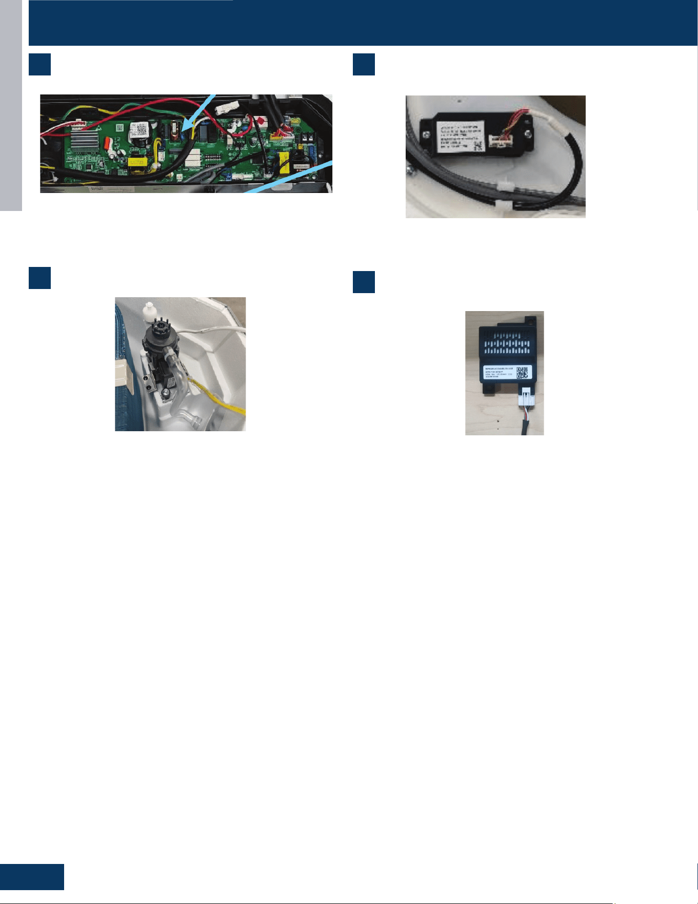
CASSETTE
D4
ENGLISH
control decisions are made by the outdoor unit ECU. The indoor board has some limited
diagnostic capability which will be covered in this manual. Condensate Pump & Float
Switch
9 Condensate Pump & Float Switch
10. Wifi
Receive and send signals, use the APP to control the air conditioning
Cooling mode (including automatic cooling operation and emergency switch setting
cooling mode) and dehumidification mode, the pump works when the compressor is on,
and the pump lags behind for 5 minutes. For other modes such as conversion heating
pump, it also continues to operate for 5 minutes according to the relevant order of the
mode.
Cooling standby, heating and fan mode, the pump does not run when the float switch is
closed. When the water tank is full, the float swit
ch is
opened,
and after the
controller detects this signal for 2 seconds, the pump starts to work. After the float
recovers, the pump continues to work with a lag of 5 minutes.
Continuous detection of water full signal for more than 5 minutes, the compressor stops
working; After the press stops, the pump continues to operate for 5 minutes. If the float
switch is still disconnected, the drainage system is reported to be faulty. After the fault,
the pump continues to operate until it is detected that the float switch is closed with a
lag of 5 minutes and the pump turns to normal operation mode.
.
8 10
9
11
Control Board WiFi
Condensate Pump & Float Switch
Refrigerant Leakage Detector
The indoor unit circuit board controls the switching functions of the
indoor unit. All control decisions are made by the outdoor unit ECU.
The indoor board has some limited diagnostic capability which will be
covered in this manual. Condensate Pump & Float Switch
Receives and sends wireless signals to enable APP control of system
operation
In cooling mode (including automatic cooling operation and
emergency switch setting cooling mode and dehumidication mode),
the pump operates when the compressor is on, and the pump 5
minutes after. For other modes such as conversion heating pump, it
also continues to operate for 5 minutes after.
Cooling standby, heating and fan mode, the pump does not run.
When the oat switch is opened, the water tank is full.
After the controller detects this signal for 2 seconds, the pump starts
to work. After the oat recovers, the pump continues to work 5 for an
additional minutes.
Continuous detection of water full signal for more than 5 minutes, will
stop the compressor. The pump continues to operate for 5 minutes.
If the oat switch is still open or disconnected, the drainage system is
reported to be faulty. After the fault, the pump continues to operate
until it is detected that the oat switch is closed or for 5 minutes.
Detects the concentration of refrigerant in the air. When the
refrigerant leakage sensor detects a concentration = 10% of lower
ammability limit, an alarm is triggered.
bA No refrigerant leakage detector is installed.
1. The sensor is not detected.
2. If the bA fault is still reported, the refrigerant sensor is abnormal.
AA LFL leakage higher than X% is detected.
1. Cut o the refrigerant, whether Ab is displayed after the
refrigerant drops. If so, the sensor is normal; If Ab is not displayed
consistently after the refrigerant concentration decreases, the
detector is abnormal and needs to be replaced.
AC Communication failure.
1. Check wiring connections. If the fault persists, replace the sensor
cable.
Ad Self-check fault.
1. The refrigerant sensor is missing (open circuit), install a new
detector.
2. Detector bypass (short circuit). Replace the detector wiring
harness. If the fault persists, replace the detector.
3. Detector output exceeds the declared range of the sensor or the
expected state is abnormal, replace the refrigerant sensor.
AE/AF Detector life warning
1. The fault is cleared after a new sensor is installed. If the fault
persists, it may be a drive board fault.
Dip Switch SW1-5:
0: Refrigerant leakage detector function valid
1: Refrigerant leakage detector function invalid
COMPONENTS
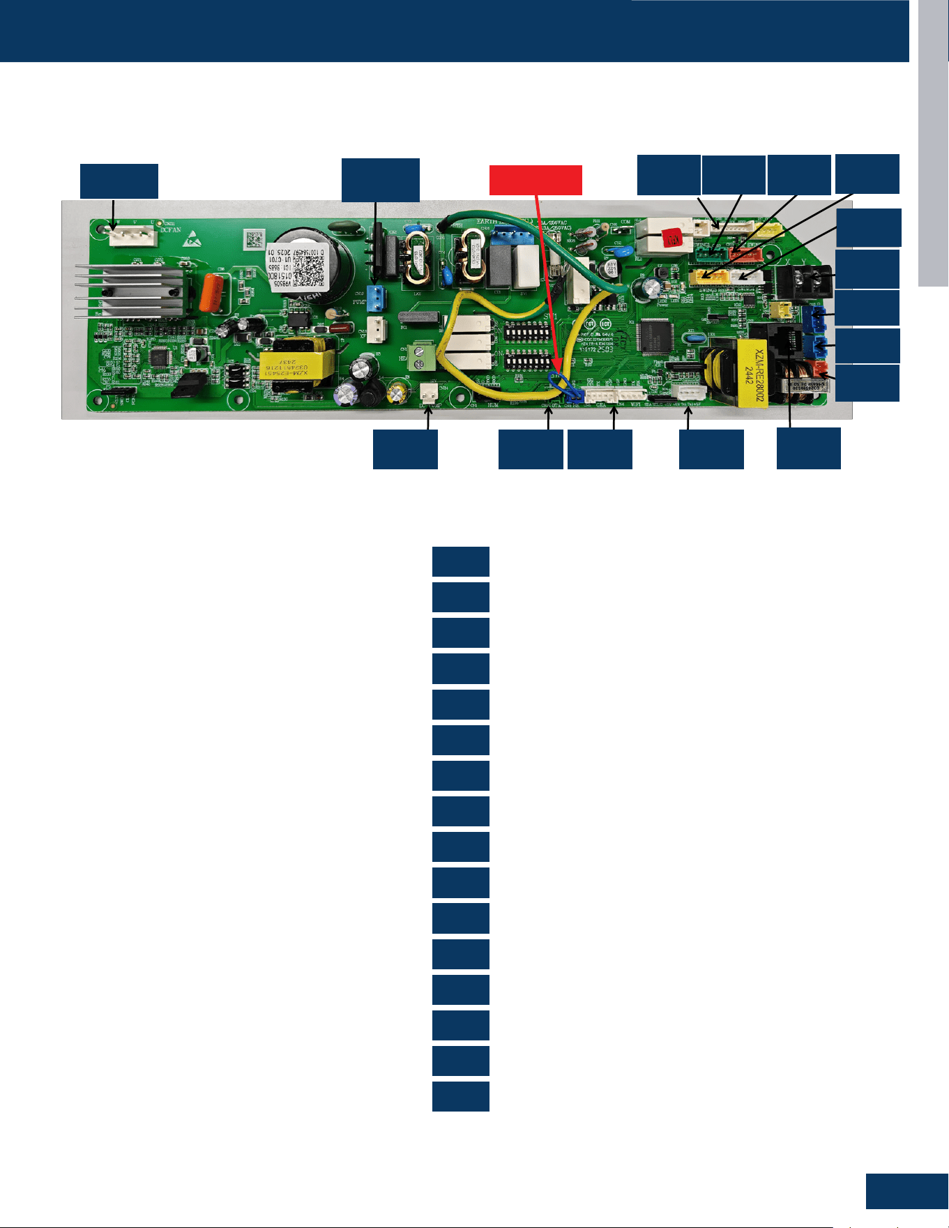
CASSETTE
D5
ENGLISH
0151800985
US09CB2BEA US12CB2BEA US18CB2BEA US24LB2BEA US30LB2BEA US36LB2BEA
CN2
CN3
CN5
CN7
CN8
CN10
CN11
CN17
CN211
CN11
CN10
CN23
CN3
CN8
CN19
CN7
CN22
CN18
CN21
CN17
CN20
CN2
CN5
CN24
CN18
CN19
CN20
CN21
CN22
CN23
CN24
CN211
COMPONENTS
PCB Overview
RJ45 Communication
Remote Control
WiFi
Sensor
Float Switch
Wired Controller
Light Board
Swing Motor
Swing Motor
AC Drain Pump
Swing Motor
Swing Motor
OTA485 Communication
Refrigerant Sensor
DC Drain Pump
Fan Motor
0151800985
CN211
CN19
CN11
CN18
CN21
CN17
CN17
CN10
CN23
CN3
CN8
CN2
CN7CN5CN22CN24
CN2
CN3
CN5
CN10
CN18
CN21
CN7
CN11
CN19
CN22
CN24
CN8
CN17
CN20
CN23
CN211
JUMPER
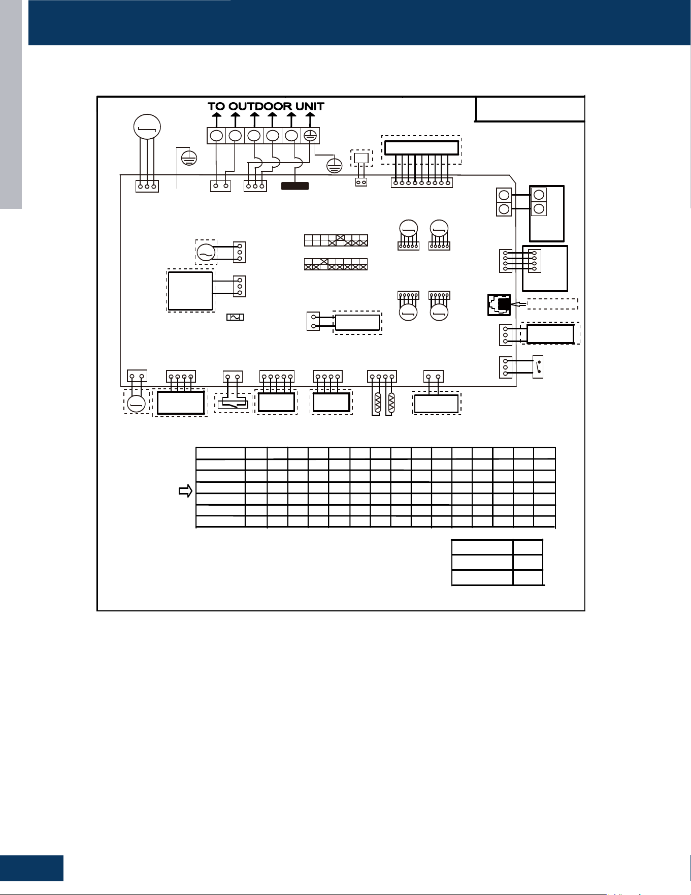
CASSETTE
D6
ENGLISH
WIRING DIAGRAM
US24LB2BEA / US30LB2BEA / US36LB2BEA
F a c t o r y de f au l t s e t t i ng
o f t he D I P s w i t c h e s
S W 1 - 1 S W 1 - 2 S W 1 - 3 S W 1 - 4 S W 1 - 6 S W 1 - 7 S W 1 - 8 S W 3 - 1 S W 3 - 2 S W 3 - 3 S W 3 - 4 S W 3 - 5 S W 3 - 6 S W 3 - 7 S W 3 - 8
US09CB2BEA
M O D E L
OFF O FF OFF O F F O F F O F F O F F O F F O F F O F F O F F O F F O F F
ON
O F F OFF O F F O F F O F F O F F O F F O F F O F F O F F O F F O F F
O F F O F F O F F O F F O F F O F F O F F O F F O F F O F F
O N
O FF
ON O N
O F F O F F O F F O F F O F F O F F O F F O F F O F F O F F
US12CB2BEA
US18CB2BEA
US24LB2BEA
US30LB2BEA
ON
OFF
OFF
O F F O F F O F F F O F F
O F
O F F O F F O F F O F F
O F F
O FF
ON
O FF
N O T E :
1 . D a s h e d
p a r t s a r e op t
i on a l .
2 . P l e a s e r e f e r t o s e r v i c e m a n ua l t o g e t d e t a i l s o f t h e D I P s w i t c he s d e f i n i t i o n .
3 . D o n o t c h ang e t h e D I P s w i t c h e s s e t t i ng w i t h o u t t e c hn i c a l s u p p o r t .
4 .G e t d e t a i l s f r o m t r ou b l e s h o o t i n g l i s t ab o u t L E D i nd i c a t i o n.
5 . A b b r e v i a t i o n
:
R D - r e d, W - w i t h e , B L K - b l a c k, B L U - b l u e , G R N - g r e e n , Y L - y e l l o w , Y / G - y e l l o w / g r ee n , E . A . O :
e x t e r n a l a l a r m o u t p u t, T r
:
i n d o o r u n i t a m b i e n t ( r oo m ) t e m p e r a t u r e s e n s o r , T p
:
i n d o o r u n i t p i p e ( c o i l )
t e m p e r a t u r e s en s o r .
6 . T he po r t C N 4 & C N 1 0 a r e d r y c o n t a c t o u t p u t po r t f o r p a r t i c u l a r u s e , do n o t c o n n e c t o t h e r d e v i ce w i t h ou t
t e c h n i c a l pe r s on s uppo r t .
US36LB2BEA
OFF OFF OFF OFF OFF OFF OFF OFF OFF OFF OFF ON ON
UVC
1 2 3
H1 H2
M
Display PCB
M
M
M M
X Y
WIRED
CONTROLLER
Y X
CN23
BLU
Air conditioning
refrigerant detector
DC Water Pump
GEA
WIFI MODULE
WIFI MODULE
Tp
Tr
DC FAN
FLOAT SWITCH
CN8
Central Controller
CN3
CN7 CN4
CN5 CN9 CN3
CN2
BLK
TO RJ45 device
Humidity Sensor
CN1 CN24
M
Room Card
M
FRELAY FOR
FRESH AIR
MOTOR(dry
Contact,rating
-230VAC,3A)/
E.A.0
AC Water Pump
FRELAY FOR
Electric Heater
CN17 CN20
YL
CN18 CN21
WH
GR RD
WH
CN19
BLU
CN15
WH
CN13
GR
CN211
WH
CN16
BLU
CN6
CN14
WH
CN11
WH
ON SW1
ON SW3
BLU
WH WH
YL
CN22
GRN
WH
BLK
RD BLU
CN10
G/Y
RD
BLK
WH
YL
YL
SWING1
M
SWING1 SWING2
SWING3 SWING4
BRN
RD
OFF
OFF ON
OFF ON
OFF ON
OFF ON
OFF ON
G/Y
Emergency
Stop
FUSE1
T6.3A 250VAC
(T8.0A 250VAC)
Possible reasons
I n do o r un i t t r ou b l e s h o o t i n g
0150577394
Wired
controller
display
07 flashing
on the upper
right corner
Outdoor error
code +20 cor-
respond HEX
code
Note:
1.To get much more details about the out door unit failure,please refer tothe outdoor unit trouble
shooting list.
2.SW1-5OFF Start the refrigerant sensor function,SW1-5ON Disable the refrigerant sensor function.
Panel
display
bA
The refrigerant det-
ector is not installed
bA
No refrigerant detector is installed
AA
AA
Refrigerant leakage
Fault “AA” cannot be cleared. Only the
leakage concentration decreases and
the fault is turned to “Ab”.See the te-
chnical manual for elimination
Ac
Ac
The communication
of the refrigerant se-
nsor is faulty
When the air conditioner is running, t-
he cable harness of the refrigerant se-
nsor falls off.
Ad
Ad
The refrigerant sens-
or self-check is faulty
The refrigerant sensor is faulty.
AE
AE
Refrigerant sensor
life threshold
Refrigerant sensor life threshold rem-
inder
AF
AF
The refrigerant sens-
or expires
Refrigerant sensor life threshold, ne-
ed to be replaced
E1
E2
E4
F1-F45
01
02
04
07
0C
E7
E8
E12
E13
E14
0D
0E
Contents of Malfun-
ction
Malfunction of indoor
unit ambient tempera-
ture sensor
Malfunction of indoor-
unit piping temperatur-
e sensor
EEPROM wrong ofin-
door PCB
Abnormal communic-
ation between indoor
and outdoor units
Abnormal communic-
ation between wiredc-
ontroller and indoor
unit
Malfunction of drain-
system
Zero cross sigal wr-
ong
Indoor unit DC fanm-
otor abnormal
Outdoor unit error
Sensor disconected,or broken,or at
wrong position,orshort circuitsor.
Sensor disconected,or braken,or at
wrong position,orshort circuit.
EEPROM chip disconectedor broken
or wrong programmed,or PCB broken.
Wrong connection,or thewires be dis-
conected or wrong adress setting of
indoorunit or faulty power supplyor fa-
ulty PCB
Wrong connection or wiredcontroller
broken,or PCB faulty.
Pump motor disconnectedor at wrong
position,or thefloat switch,disconnec-
ted,or at wrong position, or theshort
circuit bridge disconneted
Zero cross sigal detected wrong.
DC Fan motor disconnectedor DC
Fan broken or circuitbroken
See correspond Outdoorunit error tro-
uble shooting.Remark: F1 means ou-
tdoor error code 1, F2 meansoutdoor
error code 2, andso on.
Led2 flash times
tens
place
ones
place
0
1
0
0
0
0
0
0
0
2
4
7
8
12
13
14
M(≥2)
N(≥0)
18
6
17
0
17
2
17
3
17
4
17
5
SW1-5
Refrigerant Sensors
have
no
OFF
ON
G/Y
CON1
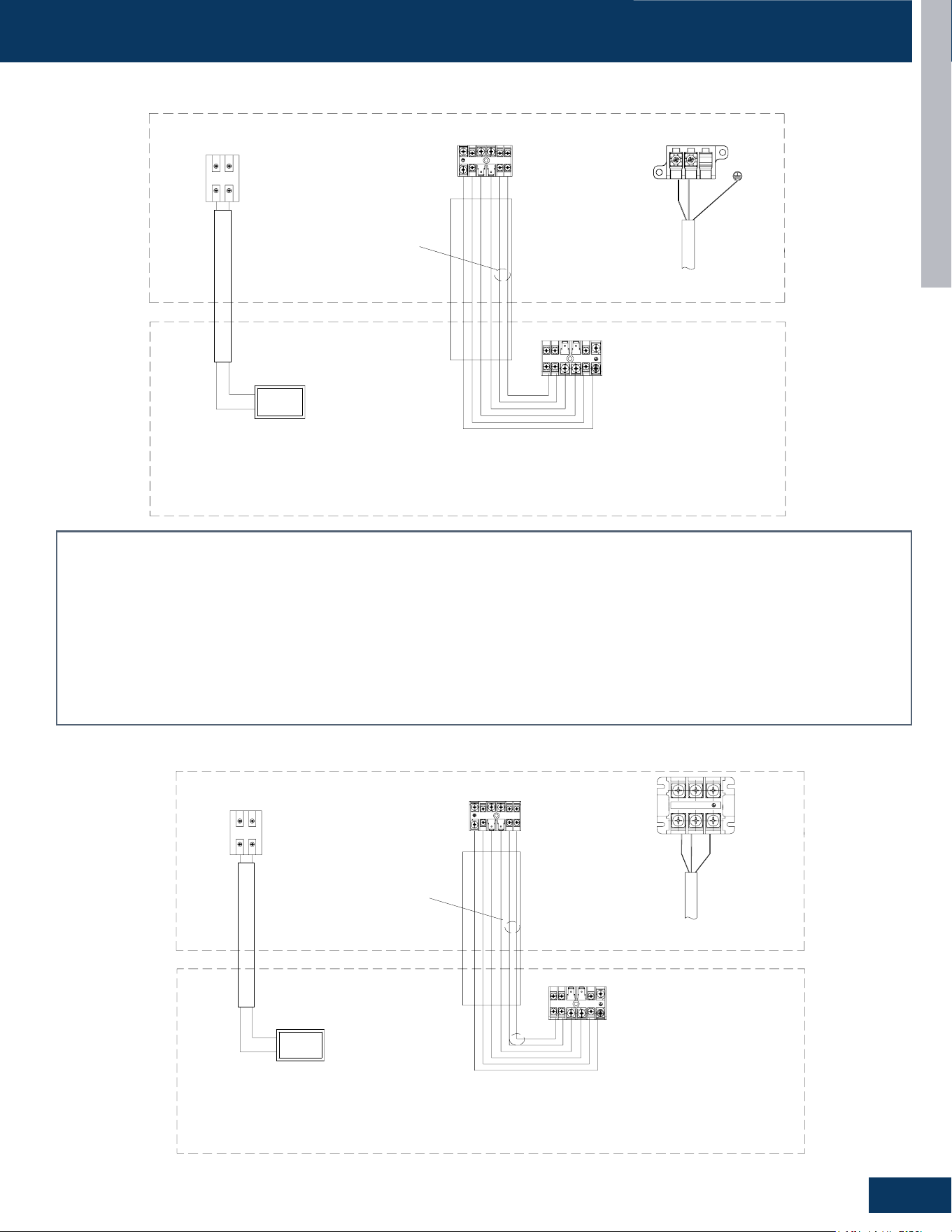
CASSETTE
D7
ENGLISH
OUTDOOR/INDOOR WIRING CONNECTIONS
US24LB2BEA
Indoor Unit B
C1 C2
OTA
the Indoor Unit
Central Controller
@2
@4
A
B
@3
These communication cable
should be shielded twisted
pair type.
Central
Controller
Outdoor Unit
Power supply cable, 3*4mm²
Communication cable for indoor unit and outdoor unit,4*2.5mm²
Caution
:
①
The OTA communication cable should be shielded twisted pair type,
and need to make the cable's shielded layer connect to earth or the unit
shell which connect to earth (indoor side or outdoor side).
②
There should be independent pipeline for communication wire.
③
The distance between OTA communication cable and the power supply
cable should be at least 10cm.
④
Ensure specifically that there is an earth leakage breaker (ELB)
installed for both the outdoor and indoor unit.
⑤
If the installation is already fitted with an earth leakage breaker (ELB),
ensure that its rated current is large enough to withstand the current of the
units (both outdoor and indoor).
@3:
@1:
@2:
Communication cable for central controller, wire specification to
refer to wired controller manual and real installation length.
@4:
The OTA communication cable (H1/H2) should be 2 x 16 AWG shielded.
Indoor Unit
Power Supply
1Ph,208/230V,60Hz
Power
@1
L1
L2
H1
H2 1
2
3
H1
H2 1
2
3
Caution:
1. The OTA communication cable should be shielded twisted pair type, and need to make the cable’s shielded layer connect to earth or the unit shell which
connect to earth (indoor side or outdoor side).
2. There should be independent pipeline for communication wire.
3. The distance between OTA communication cable and the power supply cable should be at least 10cm.
4. Ensure specically that there is an earth leakage breaker (ELB) installed for both the outdoor and indoor unit.
5. If the installation is already tted with an earth leakage breaker (ELB), ensure that its rated current is large enough to withstand the current of the units (both
outdoor and indoor).
@1 Power supply cable, 3*4mm²
@2 Communication cable for indoor unit and outdoor unit,4*2.5mm²
@3 Communication cable for central controller, wire specication to refer to wired controller manual and real installation length.
@4 The OTA communication cable (H1/H2) should be 2 x 16 AWG shielded.
Indoor Unit B
C1 C2
OTA
the Indoor Unit
Central Controller
@2
@4
A
B
@3
These communication cable
should be shielded twisted
pair type.
Central
Controller
Outdoor Unit
Power supply cable, 3*4mm²
Communication cable for indoor unit and outdoor unit,4*2.5mm²
Caution
:
①
The OTA communication cable should be shielded twisted pair type,
and need to make the cable's shielded layer connect to earth or the unit
shell which connect to earth (indoor side or outdoor side).
②
There should be independent pipeline for communication wire.
③
The distance between OTA communication cable and the power supply
cable should be at least 10cm.
④
Ensure specifically that there is an earth leakage breaker (ELB)
installed for both the outdoor and indoor unit.
⑤
If the installation is already fitted with an earth leakage breaker (ELB),
ensure that its rated current is large enough to withstand the current of the
units (both outdoor and indoor).
@3:
@1:
@2:
Communication cable for central controller, wire specification to
refer to wired controller manual and real installation length.
@4:
The OTA communication cable (H1/H2) should be 2 x 16 AWG shielded.
Indoor Unit
Power Supply
1Ph,208/230V,60Hz
Power
@1
H1
H2 1
2
3
L1
L2
H1
H2 1
2
3
US30LB2BEA / US36LB2BEA

CASSETTE
D8
ENGLISH
DIP SWITCH & JUMPER SETTINGS
SW1-1 SW1-2 SW1-3 SW1-4 SW1-5 SW1-6 SW1-7 SW1-8 Description
ON ON OFF - - - - - 24K
OFF OFF ON - - - - - 30K
ON OFF ON - - - - - 36K
- - - OFF - - - - Room Card Valid
- - - ON - - - - Room Card Invalid
- - - - OFF - - - Refrigerant Detector Functional
- - - - ON - - - The Refrigerant Detector Invalid
- - - - - OFF - - Fresh Air
- - - - - ON - - Fault Alarm
- - - - - - OFF - None - Filter Alarm Reminder + Refrigeration Fan Stops
- - - - - - ON - Filter Alarm Reminder + Refrigeration Fan Does Not Stop
- - - - - - - OFF Us Models
- - - - - - - ON Non-Us Models
DIP SW1
SW3-1 SW3-2 SW3-3 SW3-4 SW3-5 SW3-6 SW3-7 SW3-8 Description
OFF - - - - - - - Special Fresh Air Selection For Duct Unit: Valid
ON - - - - - - - Special Fresh Air Selection For Duct Unit: Invalid
- OFF - - - - - -
Cassette Single Swing Wind - Synchronized Swing Of
Swing Blades
- ON - - - - - -
Cassette Unit Four Swing Wind - Four Swing Blades
Swing At Dierent Angles, Misaligned Swing
- - OFF - - - - - Electrical Heating: Invalid
- - ON - - - - - Electrical Heating: Valid
- - - OFF - - - -
Model: Ultra-Slim Ducted Unit With 4-Level Static
Pressure
- - - ON - - - -
Model: Medium Static Pressure Duct With 10-Level
Static Pressure Adjustment
- - - - OFF OFF OFF OFF 0# (Wired Control Main) (Default)
- - - - OFF OFF OFF ON 1# (Line-Controlled Sub Machine)
- - - - OFF OFF ON OFF 2# (Line-Controlled Sub Machine)
- - - - OFF OFF ON ON 3# (Line-Controlled Sub Machine)
- - - - - - - - --
- - - -
ON ON ON ON 15# (Line-Controlled Sub Machine)
DIP SW3
RJ1 RJ2 RJ3 SW3-2 SW3-3 Description
OFF OFF OFF OFF OFF Crane
OFF OFF OFF OFF ON Cassette With 1 Oscillating Wind
OFF OFF OFF ON OFF Cassette With Four-Way Oscillating Wind
OFF OFF OFF ON ON Cassette With Light Panel
OFF OFF ON OFF OFF Console
OFF ON OFF OFF OFF Small Duct
OFF ON OFF OFF ON High-Capacity Duct
- - - - - Reserve
Jumper Settings - Model Identication
SW3_1 The fan selection function in cooling mode is only applicable to duct and slim duct.
SW3_4 Only applicable to slim duct
Suitable for convertible, 2HP cassette (matched with single swing wind), 2HP cassette (matched with four swing wind), 3HP cassette (equipped
with display board). For example, if the convertible has 0 0 0 0, the resistance should be welded RJ1/RJ2/RJ3. Simultaneously dial the second
digit of code BM3 to OFF and the third digit to OFF. The same setup method is used for other models.
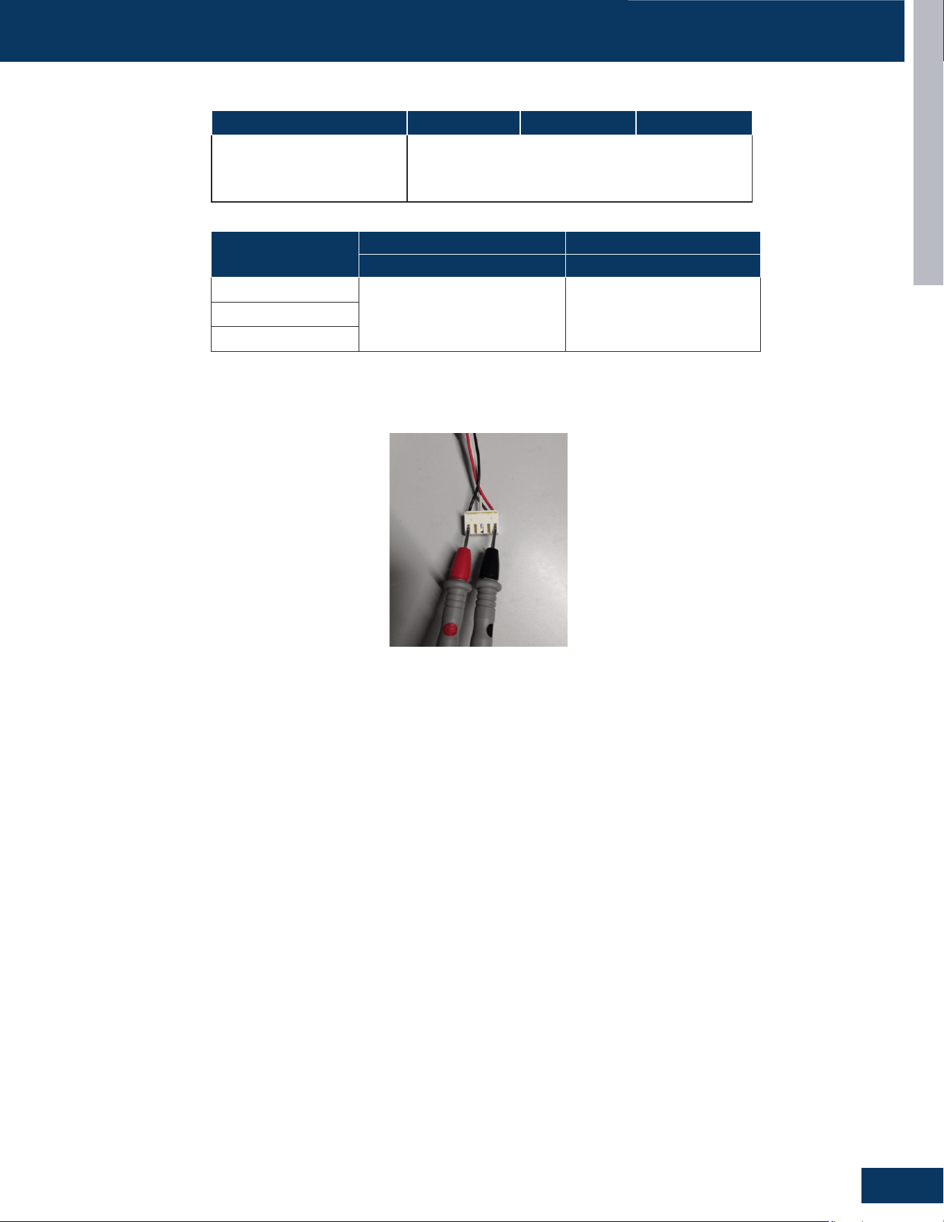
CASSETTE
D9
ENGLISH
SERVICE PROCEDURES
Resistance Values
Measure the Resistance :
Use a multimeter to measure the resistance between any two phases (U, V, W) of the motor (as shown in the following diagram).
US24LB2BEA US30LB2BEA US36LB2BEA
Fan Motor Resistance Value 0150401755C-100W, 28.7Ω±10v
Louver Resistance Value
0150401794A, 300Ω±7%
0150401794B, 300Ω±7%
Model
Ambient temperature sensor Pipe temperature sensor
Resistance Value Resistance Value
US24LB2BEA
R25=10KΩ±3%
B25/50=3700K±3%
R25=10KΩ±3%
B25/50=3700K±3%
US30LB2BEA
US36LB2BEA

[This page left intentionally blank]

MID-STATIC DUCTED
E1
ENGLISH
MID-STATIC DUCTED
US24MB2BEA
US30MB2BEA
US36MB2BEA
TABLE OF CONTENTS
COMPONENTS ....................................................................................................................................................................... E2
Evaporator Coil .......................................................................................................................................................................E2
Blower Assembly ....................................................................................................................................................................E2
3 Terminal Block ...................................................................................................................................................................... E2
Control Board ..........................................................................................................................................................................E2
Ambient Temperature Sensor ...............................................................................................................................................E2
Piping Temperature Sensor ...................................................................................................................................................E2
Condensate Pump ..................................................................................................................................................................E3
Gravity Drain Ports ................................................................................................................................................................. E3
PCB Overview .........................................................................................................................................................................E3
WIRING DIAGRAM ................................................................................................................................................................... E4
OUTDOOR/INDOOR WIRING CONNECTIONS
........................................................................................................................ E5
DIP SWITCH & JUMPER SETTINGS
......................................................................................................................................... E6
SERVICE PROCEDURES
.......................................................................................................................................................... E7
Resistance Values ................................................................................................................................................................... E7
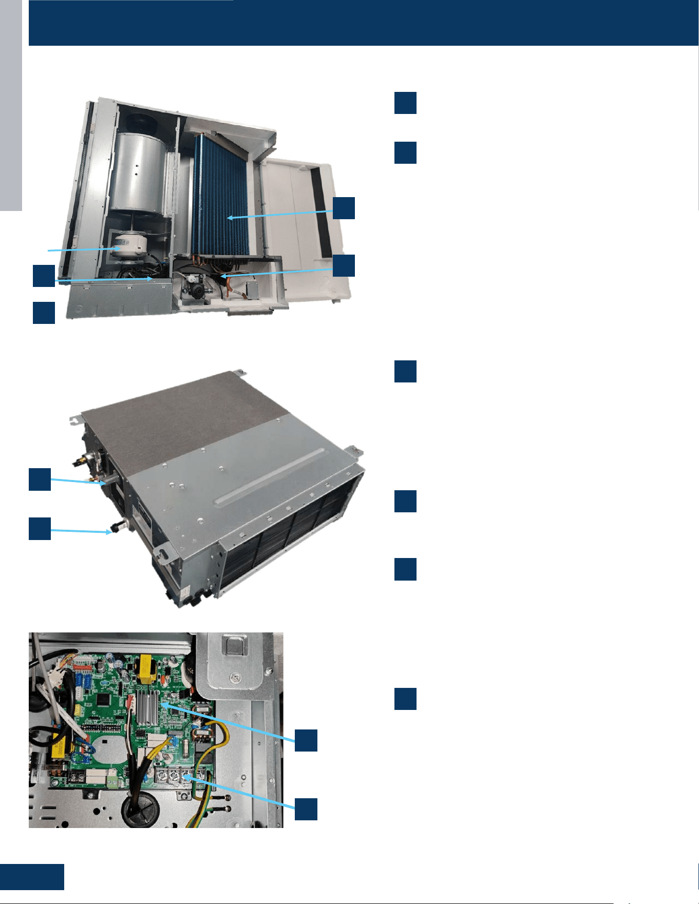
MID-STATIC DUCTED
E2
ENGLISH
COMPONENTS
US09MB2BEA / US12MB2BEA / US18MB2BEA
7
8
2
1
5
6
7
8
7
8
2
1
5
6
2
5
1
6
1. Evaporator Coil
2. Blower Assembly
The indoor unit features a DC variable speed blower motor that will change speed to
match the capacity demand from the outdoor unit. The motor powers blower assembly.
The blower assembly consists of 2 plastic blowers. A set screw holds each blower wheel
to the blower motor.
The indoor blower motor is connected to the indoor unit control board. The wiring from
the motor to indoor board consists of 3 wires connected to pins that deliver line v
oltage.
During normal operation, the indoor control board will energize the indoor blower
motor and request proper speed.
3
. Terminal Block
Power to operate the indoor unit comes from the electrical line voltage terminal block at
the outdoor unit. The wiring includes 4 wires, 1, 2, S and ground. Wires 1 and S complete
the data path. These wires should always be
14
gauge
AWG
stranded
cooper,
non-
shielded
type wire. Splices in wires 1 or S may cause communication errors.
3
4
4
3
1
Evaporator Coil
2
Blower Assembly
The indoor unit features a DC variable speed blower motor
that will change speed to match the capacity demand from
the outdoor unit. The motor powers blower assembly.
The blower assembly consists of 2 plastic blowers. A set
screw holds each blower wheel to the blower motor.
The indoor blower motor is connected to the indoor unit
control board. The wiring from the motor to indoor board
consists of 3 wires connected to pins that deliver line
voltage.
During normal operation, the indoor control board will
energize the indoor blower motor and request proper
speed.
3
Terminal Block
Power to operate the indoor unit comes from the electrical
line voltage terminal block at the outdoor unit. The wiring
includes 4 wires, 1, 2, S and ground. Wires 1 and S complete
the data path. These wires should always be 14 gauge AWG
stranded cooper, non-shielded type wire. Splices in wires 1
or S may cause communication errors.
5
Ambient Temperature Sensor
The Ambient Temperature Sensor senses room
temperature. This sensor provides room temperature
information to the ECU for calculation of inverter capacity
and temperature control. Both sensors are negative
temperature coecient type that reduce electrical
resistance as temperature rises.
6
Piping Temperature Sensor
The Piping Temperature Sensor senses indoor coil
temperature in the cooling mode and in the heating mode.
This sensor is used for Anti Freezing and Anti Cold Blow
cycles. The sensor also provides critical temperature
information to the ECU that may be used in frequency
adjustments.
4
Control Board
Located under the electrical control box cover.
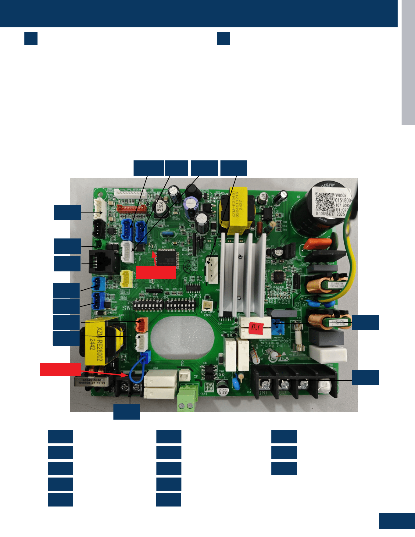
MID-STATIC DUCTED
E3
ENGLISH
COMPONENTS
US24MB2BEA / US30MB2BEA / US36MB2BEA
7
Condensate Pump
The Duct unit has a built-in condensate pump. The pump is
connected to the circuit board. The pump is energized whenever
the Float Switch indicates that water needs to be pumped from the
cassette. The oat switch connects onto the circuit board.
The oat switch and pump are located behind the removable
insulated cover next to the electrical control box. The pump is
hermetically sealed and requires no maintenance. The oat switch is
a normally closed switch, that opens as water rises. The oat switch
requires no maintenance.
8
Gravity Drain Ports
The indoor units have the option for either gravity drain systems or
the use of an internal condensate pump with oat switch. If high lift
is required, the water from the duct unit should be pumped to a eld
condensate pump that is capable of high lift.
Note: If the Internal condensate pump is not used (only gravity drain),
the condensate pump must be disconnected from the PCB (CN4).
Power Supply
OTA
Refrigerant Sensor
Drain Pump
Fan Motor
Wired Controller
Remote Communication
Up-and-Down Swing
Float Switch
WiFi
RJ45 Communication
Left and Right Swing
Sensor
PCB Overview
0151800986
US09MB2BEA US12MB2BEA US18MB2BEA US24MB2BEA US30MB2BEA US36MB2BEA US42MB2BEA US48MB2BEA
CN1
CN2
CN3
CN4
CN6
CN7
CN9
CN41
CN4
CN1
CN7
CN13
CN3
CN9
CN17
CN2
CN15
CN11-1
CN6
CN11
CN35
CN11
CN11-1
CN13
CN15
CN17
CN35
CN41
CN11-1 CN11 CN35
CN15
CN4
CN1
CN2
CN7
CN17
CN9
CN3
CN13
CN41
CN6
CN1 CN7 CN17
CN2 CN9 CN35
CN3
CN11-1
CN41
CN4 CN13
CN6 CN15
0151800986
JUMPER
LED 9
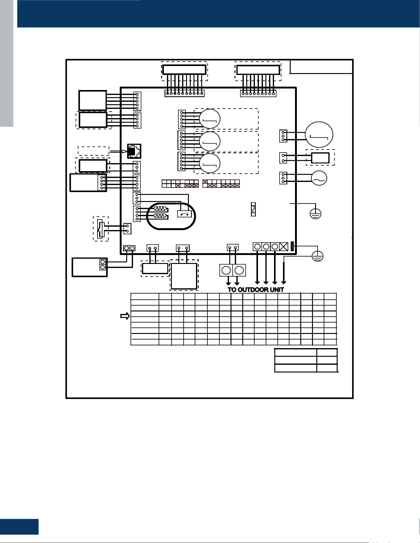
MID-STATIC DUCTED
E4
ENGLISH
WIRING DIAGRAM
US24MB2BEA / US30MB2BEA / US36MB2BEA
Factory default setting
of the DIP switches
SW1-1 SW1-2 SW1-3 SW1-4 SW1-6 SW1-7 SW1-8 SW3-1 SW3-2 SW3-3 SW3-4 SW3-5 SW3-6 SW3-7 SW3-8
US09MB2BEA
MODEL
OFF OFF OFF OFF OFF OFF OFF ON OFF OFF OFF OFF OFF OFF
ON
0150577393
OFF OFF OFF OFF OFF OFF OFF OFF OFF OFF OFF OFF
ON
OFF OFF OFF OFF OFF OFF OFF OFF OFF OFF
ON
OFF
ON ON
OFF OFF OFF OFF OFF OFF OFF OFF OFF OFF
ON
ON
US12MB2BEA
US18MB2BEA
US24MB2BEA
US30MB2BEA
ON
OFF
OFF
OFF OFF OFF F OFF
ON
OF
OFF
OFF OFF OFF
OFF
OFF
ON
OFF
1ESUF
CAV052/A3.6T
CN1
1(N) 2(L) 3(S)
AC PUMP
MOTOR
CN7
YL
YL
4NC
WIRED
CONTROLLER
ULB
Y/G
91NC
Y X
X Y
1 2 3
CN20
61NC
ROOM CARD
ULB
HW
14NC
Tp
Tr
31NC
FLOAT SWITCH
TO RJ45 device
3NC9NC
DR
Air conditioning
refrigerant detector
ULB
Central Controller
51NC
41NC
71NC
WIFI MODULE
Humidity Sensor
CN5
WH
FRELAY FOR
FRESH AIR
MOTOR(dry
Contact,rating
-230VAC,3A)/
E.A.0
M
UVC
93NC
HW
6NC
HW
M
DC FAN
ON SW1 ON
SW3
M
M
M
11NC1-11NC53NC
HW
ULB
ULB
KLB
Swing Motor2
Swing Motor3
Swing Motor1
LED DISPLAY
Display PCB
GRN
KLBHW
ULB
CN21
WH
CN31
RD
FRELAY FOR
Electric Heater
H1 H2
CN2
GRN
NOTE:
1.Dashed
parts are opt
ional.
2.Please refer to service manual to get details of the DIP switches definition .
3.Do not change the DIP switches setting without technical support.
4.Get details from trouble shooting list about LED indication.
5.Abbreviation
:
RD -red, W-withe,BLK-black,BLU-blue,GRN-green,YL-yellow,Y/G-yellow/green,E.A.O:
external alarm output,Tr
:
indoor unit ambient(room) temperature sensor,Tp
:
indoor unit pipe(coil)
temperatur
e
sensor.
6.The port CN10&CJ1&CJ2&CN22&P5 are dry contact output port for
particular use,do not connect other device without technical person support.
US36MB2BEA
US42MB2BEA
US48MB2BEA
OFF OFF OFF OFF OFF OFF OFF OFF OFF OFF OFF
OFF ON OFF OFF OFF OFF OFF OFF OFF OFF OFF OFFON
OFF OFF OFF OFF OFF OFF OFF OFF OFFON
ON
OFF
ON ON
ON
ON ON ON
Y/G
CON1
Wired
controller
display
07 flashing
on the upper
right corner
Outdoor error
code +20 cor-
respond HEX
code
Note:
1.To get much more details about the out door unit failure,please refer tothe outdoor unit trouble
shooting list.
2.SW1-5OFF Start the refrigerant sensor function,SW1-5ON Disable the refrigerant sensor function
Panel
display
bA
The refrigerant det-
ector is not installed
bA
No refrigerant detector is installed
AA
AA
Refrigerant leakage
Fault “AA” cannot be cleared. Only the
leakage concentration decreases and
the fault is turned to “Ab”.See the te-
chnical manual for elimination
Ac
Ac
The communication
of the refrigerant se-
nsor is faulty
When the air conditioner is running, t-
he cable harness of the refrigerant se-
nsor falls off.
Ad
Ad
The refrigerant sens-
or self-check is faulty
The refrigerant sensor is faulty.
AE
AE
Refrigerant sensor
life threshold
Refrigerant sensor life threshold rem-
inder
AF
AF
The refrigerant sens-
or expires
Refrigerant sensor life threshold, ne-
ed to be replaced
E1
E2
E4
F1-F45
01
02
04
07
0C
E7
E8
E12
E13
E14
0D
0E
Contents of Malfun-
ction
Malfunction of indoor
unit ambient tempera-
ture sensor
Malfunction of indoor-
unit piping temperatur-
e sensor
EEPROM wrong ofin-
door PCB
Abnormal communic-
ation between indoor
and outdoor units
Abnormal communic-
ation between wiredc-
ontroller and indoor
unit
Malfunction of drain-
system
Zero cross sigal wr-
ong
Indoor unit DC fanm-
otor abnormal
Outdoor unit error
Sensor disconected,or broken,or at
wrong position,orshort circuitsor.
Sensor disconected,or braken,or at
wrong position,orshort circuit.
EEPROM chip disconectedor broken
or wrong programmed,or PCB broken.
Wrong connection,or thewires be dis-
conected or wrong adress setting of
indoorunit or faulty power supplyor fa-
ulty PCB
Wrong connection or wiredcontroller
broken,or PCB faulty.
Pump motor disconnectedor at wrong
position,or thefloat switch,disconnec-
ted,or at wrong position, or theshort
circuit bridge disconneted
Zero cross sigal detected wrong.
DC Fan motor disconnectedor DC
Fan broken or circuitbroken
See correspond Outdoorunit error tro-
uble shooting.Remark: F1 means ou-
tdoor error code 1, F2 meansoutdoor
error code 2, andso on.
Possible reasons
Indoor unit trouble shooting
LED9 flash times
Tens
place
Ones
place
0
1
0
0
0
0
0
0
0
2
4
7
8
12
13
14
M(≥2)
N(≥0)
18
6
17
0
17
2
17
3
17
4
17
5
RD
BRN
SW1-5
Refrigerant Sensors
have
no
OFF
ON
ON
ON
ON
ON
ON
ON
ON
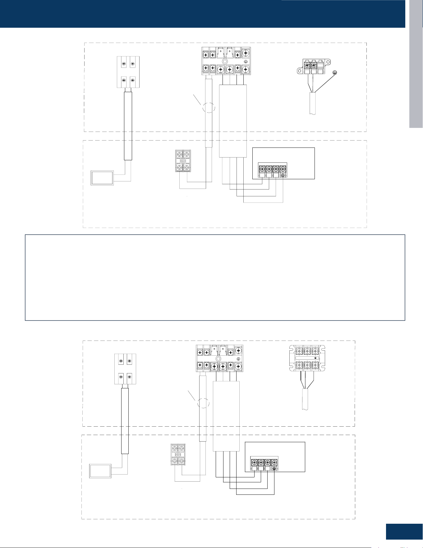
MID-STATIC DUCTED
E5
ENGLISH
OUTDOOR/INDOOR WIRING CONNECTIONS
Power Supply
1Ph,208/230V,60Hz
L1(N)
Indoor Unit --DUCT
Power
@2
@1
These communication
cable should be shielded
twisted pair type.
Outdoor Unit
Communication cable for indoor unit and outdoor unit,4*2.5mm²
Caution
:
①
The OTA communication cable should be shielded twisted pair type,
and need to make the cable's shielded layer connect to earth or the unit
shell which connect to earth (indoor side or outdoor side).
②
There should be independent pipeline for communication wire.
③
The distance between OTA communication cable and the power supply
cable should be at least 10cm.
④
Ensure specifically that there is an earth leakage breaker (ELB)
installed for both the outdoor and indoor unit.
⑤
If the installation is already fitted with an earth leakage breaker (ELB),
ensure that its rated current is large enough to withstand the current of the
units (both outdoor and indoor).
@3:
@1:
@2:
Communication cable for central controller, wire specification to
refer to wired controller manual and real installation length.
@4:
The OTA communication cable (H1/H2) should be 2 x 16 AWG
shielded.
Indoor Unit
PCB
Power supply cable, 3*4mm² for 9k/12k/18k/24k/36k,3*6mm² for
42k/48k
C1 C2
@4
H1
@3
B
A
Central
Controller
H2
L1
L2
L2(L)
H1
H2 1
2
3
S
US24MB2BEA
Caution:
1. The OTA communication cable should be shielded twisted pair type, and need to make the cable’s shielded layer connect to earth or the unit shell which
connect to earth (indoor side or outdoor side).
2. There should be independent pipeline for communication wire.
3. The distance between OTA communication cable and the power supply cable should be at least 10cm.
4. Ensure specically that there is an earth leakage breaker (ELB) installed for both the outdoor and indoor unit.
5. If the installation is already tted with an earth leakage breaker (ELB), ensure that its rated current is large enough to withstand the current of the units (both
outdoor and indoor).
@1 Power supply cable, 3*4mm² for 9k/12k/18k/24k/36k,3*6mm² for 42k/48k
@2 Communication cable for indoor unit and outdoor unit,4*2.5mm²
@3 Communication cable for central controller, wire specication to refer to wired controller manual and real installation length.
@4 The OTA communication cable (H1/H2) should be 2 x 16 AWG shielded.
US30MB2BEA / US36MB2BEA
Indoor Unit --DUCT
@2
These communication
cable should be shielded
twisted pair type.
Outdoor Unit
Communication cable for indoor unit and outdoor unit,4*2.5mm²
Caution
:
①
The OTA communication cable should be shielded twisted pair type,
and need to make the cable's shielded layer connect to earth or the unit
shell which connect to earth (indoor side or outdoor side).
②
There should be independent pipeline for communication wire.
③
The distance between OTA communication cable and the power supply
cable should be at least 10cm.
④
Ensure specifically that there is an earth leakage breaker (ELB)
installed for both the outdoor and indoor unit.
⑤
If the installation is already fitted with an earth leakage breaker (ELB),
ensure that its rated current is large enough to withstand the current of the
units (both outdoor and indoor).
@3:
@1:
@2:
Communication cable for central controller, wire specification to
refer to wired controller manual and real installation length.
@4:
The OTA communication cable (H1/H2) should be 2 x 16 AWG
shielded.
Indoor Unit
PCB
Power supply cable, 3*4mm² for 9k/12k/18k/24k/36k,3*6mm² for
42k/48k
C1 C2
@4
H1
@3
B
A
Central
Controller
H2
Power Supply
1Ph,208/230V,60Hz
Power
@1
L1(N) L2(L )
H1
H2 1
2
3
S
L1
L2
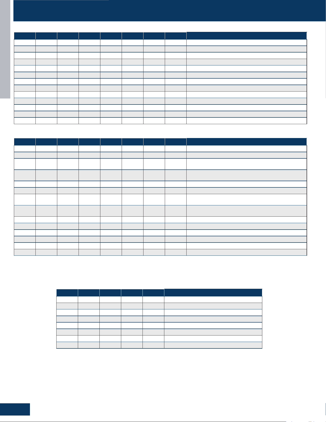
MID-STATIC DUCTED
E6
ENGLISH
DIP SWITCH & JUMPER SETTINGS SERVICE PROCEDURES
SW1-1 SW1-2 SW1-3 SW1-4 SW1-5 SW1-6 SW1-7 SW1-8 Description
ON ON OFF - - - - - 24K
OFF OFF ON - - - - - 30K
ON OFF ON - - - - - 36K
- - - OFF - - - - Room Card Valid
- - - ON - - - - Room Card Invalid
- - - - OFF - - - Refrigerant Detector Functional
- - - - ON - - - The Refrigerant Detector Invalid
- - - - - OFF - - Fresh Air
- - - - - ON - - Fault Alarm
- - - - - - OFF - None - Filter Alarm Reminder + Refrigeration Fan Stops
- - - - - - ON - Filter Alarm Reminder + Refrigeration Fan Does Not Stop
- - - - - - - OFF Us Models
- - - - - - - ON Non-Us Models
DIP SW1
SW3-1 SW3-2 SW3-3 SW3-4 SW3-5 SW3-6 SW3-7 SW3-8 Description
OFF - - - - - - - Special Fresh Air Selection For Duct Unit: Valid
ON - - - - - - - Special Fresh Air Selection For Duct Unit: Invalid
- OFF - - - - - -
Cassette Single Swing Wind - Synchronized Swing Of
Swing Blades
- ON - - - - - -
Cassette Unit Four Swing Wind - Four Swing Blades
Swing At Dierent Angles, Misaligned Swing
- - OFF - - - - - Electrical Heating: Invalid
- - ON - - - - - Electrical Heating: Valid
- - - OFF - - - -
Model: Ultra-Slim Ducted Unit With 4-Level Static
Pressure
- - - ON - - - -
Model: Medium Static Pressure Duct With 10-Level
Static Pressure Adjustment
- - - - OFF OFF OFF OFF 0# (Wired Control Main) (Default)
- - - - OFF OFF OFF ON 1# (Line-Controlled Sub Machine)
- - - - OFF OFF ON OFF 2# (Line-Controlled Sub Machine)
- - - - OFF OFF ON ON 3# (Line-Controlled Sub Machine)
- - - - - - - - --
- - - -
ON ON ON ON 15# (Line-Controlled Sub Machine)
DIP SW3
RJ1 RJ2 RJ3 SW3-2 SW3-3 Description
OFF OFF OFF OFF OFF Crane
OFF OFF OFF OFF ON Cassette With 1 Oscillating Wind
OFF OFF OFF ON OFF Cassette With Four-Way Oscillating Wind
OFF OFF OFF ON ON Cassette With Light Panel
OFF OFF ON OFF OFF Console
OFF ON OFF OFF OFF Small Duct
OFF ON OFF OFF ON High-Capacity Duct
- - - - - Reserve
Jumper Settings - Model Identication
SW3_1 The fan selection function in cooling mode is only applicable to duct and slim duct.
SW3_4 Only applicable to slim duct
Suitable for convertible, 2HP cassette (matched with single swing wind), 2HP cassette (matched with four swing wind), 3HP cassette (equipped
with display board). For example, if the convertible has 0 0 0 0, the resistance should be welded RJ1/RJ2/RJ3. Simultaneously dial the second
digit of code BM3 to OFF and the third digit to OFF. The same setup method is used for other models.
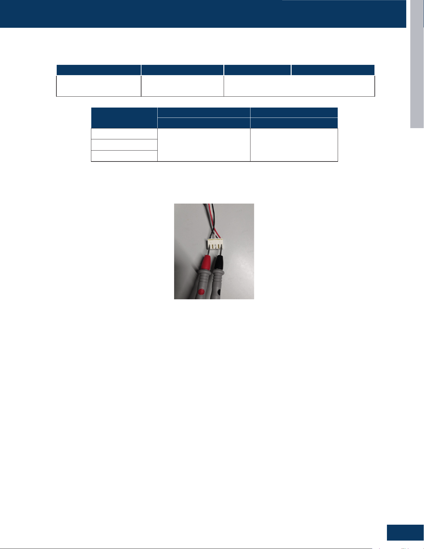
MID-STATIC DUCTED
E7
ENGLISH
SERVICE PROCEDURES
Resistance Values
Measure the Resistance :
Use a multimeter to measure the resistance between any two phases (U, V, W) of the motor (as shown in the following diagram).
Model
Ambient temperature sensor Pipe temperature sensor
Resistance Value Resistance Value
US24MB2BEA
R25=10KΩ±3%
B25/50=3700K±3%
R25=10KΩ±3%
B25/50=3700K±3%
US30MB2BEA
US36MB2BEA
US24MB2BEA US30MBB2BEA US36MBB2BEA
Fan Motor Resistance Value
0150402221C-200W,
12.5Ω±10%
0150402221DC-200W(No extended shaft)
12.5Ω±10%

[This page left intentionally blank]

TROUBLESHOOTING & REFERENCES
F1
ENGLISH
TROUBLESHOOTING & REFERENCES
TABLE OF CONTENTS
ERROR CODES ........................................................................................................................................................................ F2
TROUBLESHOOTING FLOWCHARTS
...................................................................................................................................... F4
[1] Outdoor EEPROM malfunction ........................................................................................................................................ F4
[2] Compressor Drive Module’s IPM overcurrent or short circuit ........................................................................................ F4
[4] Communication abnormal between PCB and IPM ........................................................................................................... F4
[6] Compressor Drive Module low or high voltage ............................................................................................................... F5
[8] Overheat protection for discharge temperature ............................................................................................................ F5
[9] DC fan motor fault ............................................................................................................................................................. F5
[10] Outdoor defrosting temp. sensor Te abnormal............................................................................................................. F6
[11] Suction temp.sensor Ts abnormal ................................................................................................................................. F6
[12] Outdoor ambient temp. sensor Ta abnormal ................................................................................................................ F6
[13] Discharging temp. sensor Td abnormal ......................................................................................................................... F6
[15] High pressure sensor malfunction ................................................................................................................................. F6
[16] Lack of refrigerant or discharging pipe blocked ............................................................................................................ F7
[17] 4-way valve reversing failure .......................................................................................................................................... F7
[18] Compressor motor desynchronizing ............................................................................................................................. F8
[24] Compressor startup failure ............................................................................................................................................ F8
[25] Input overcurrent of the drive module ........................................................................................................................... F8
[42] Open high pressure switch ............................................................................................................................................. F9
[43] Open low pressure switch ............................................................................................................................................F10
[44] High pressure detected in system ............................................................................................................................... F11
[45] Low pressure detected in system ................................................................................................................................F11
E1/LED1: No Flash ................................................................................................................................................................F12
E2/LED1: No Flash ................................................................................................................................................................F12
E4 ........................................................................................................................................................................................F13
F12/ LED1: 1 Flash ................................................................................................................................................................ F13
E14 ........................................................................................................................................................................................F13
E7/LED1: 15 Flash ................................................................................................................................................................F14
LED1: 21 Flash ......................................................................................................................................................................F15
LED1: 28 Flash ......................................................................................................................................................................F15
E22/LED1: 21 Flash ..............................................................................................................................................................F16
F27/LED1: 21 Flash ..............................................................................................................................................................F16
bA ........................................................................................................................................................................................F17
AA and Ab ..............................................................................................................................................................................F18
Ac ........................................................................................................................................................................................F19
Ad ........................................................................................................................................................................................F20
AE ........................................................................................................................................................................................F21
AF ........................................................................................................................................................................................ F22
SENSOR RESISTANCE TABLES .............................................................................................................................................. F23
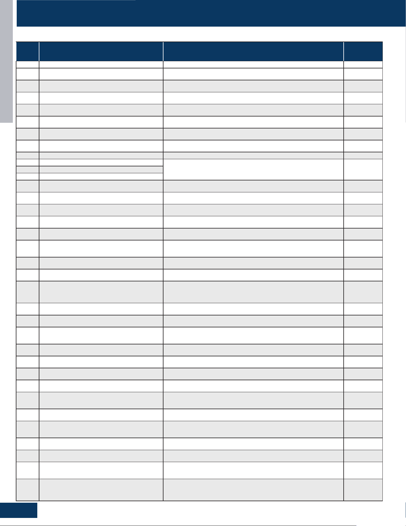
TROUBLESHOOTING & REFERENCES
F2
ENGLISH
ERROR CODES
ERROR
CODE
MALFUNCTION DESCRIPTION DIAGNOSIS AND ANALYSIS REMARK
1 EEPROM MALFUNCTION EEPROM CHIP DAMAGED OR DATA WRONG OR RELATED CIRCUIT DAMAGED RESUMABLE
2 IPM HARDWARE OVERCURRENT INPUT OVER CURRENT OCCURED BEEN DETECTED BY IPM’S HARDWARE
NON-
RESUMABLE
3
THE AC INPUT CURRENT OF THE MODULE
OVERFLOWS
THE INVERTER MODULE OF THE PRESS DETECTS THE AC INPUT CURRENT
OVERCURRENT
NON-
RESUMABLE
4
COMMUNICATION ABNORMAL BETWEEN CONTROL
BOARD AND COMPRESSOR DRIVER MODULE
CONTROL BOARD CAN NOT COMMUNICATE WITH COMPRESSOR DRIVER MODULE
OVER 4 MINUTES
RESUMABLE
5 THE COMPRESSOR MODULE IS OVERLOADED
HIGH COMPRESSOR CURRENT DETECTED BY THE PRESS FREQUENCY
CONVERSION MODULE (OVERLOAD)
RESUMABLE
6 MODULE OVER/UNDER VOLTAGE PROTECTION
THE DC VOLTAGE OR AC VOLTAGE IS TOO HIGH OR TOO LOW IN THE INVERTER
MODULE OF THE PRESS
RESUMABLE
7 COMPRESSOR IS BLOCKED OR STOPPED IMMEDIATELY
THE PRESS FREQUENCY CONVERSION MODULE DETECTS THAT THE THREE-
PHASE MODULE INPUT POWER SUPPLY IS OUT OF PHASE
RESUMABLE
8 EXHAUST TEMPERATURE TOO HIGH PROTECTION
AFTER THE COMPRESSOR IS STARTED, THE TD SENSOR IS DETECTED TO STOP FOR
3 SECONDS ABOVE 115 ° C (E)
RESUMABLE
9 DC FAN MOTOR FAULT DC FAN MOTOR DAMAGE OR NOT CONNECTED OR RELATED CIRCUIT BROKEN. RESUMABLE
10 OUTDOOR DEFROSTING TEMP. SENSOR TE ABNORMAL
SENSOR TEMPERATURE BEEN DETECTED BELOW -55°C OR HIGHER THAN 90°C OR
BEEN DETECTED AS SHORT CIRCUIT OR OPEN CIRCUIT .
RESUMABLE11 OUTDOOR SUCTION TEMP. SENSOR TS ABNORMAL
12 OUTDOOR A MBIENT TEMP. SENSOR TA ABNORMAL
13 OUTDOOR EXHAUST TEMP. SENSOR TD ABNORMAL
SENSOR TEMPERATURE BEEN DETECTED BELOW -.30°C OR HIGHER THAN 150°C
OR BEEN DETECTED SHORT CIRCUIT OR OPEN CIRCUIT
RESUMABLE
15
COMMUNICATION ABNORMAL BETWEEN INDOOR
UNIT AND OUTDOOR UNIT
OUTDOOR UNIT CONTROL BOARD CAN NOT COMMUNICATING WITH INDOOR
UNIT CONTROL BOARD OVER 4 MINUTES
RESUMABLE
16
LACK OF REFRIGERANT OR DISCHARGING PIPE
BLOCKED
THE COOLING PRESS STARTS TO DETECT THE EXHAUST OVERHEAT TD-TC≥80 ° C
(E) FOR MORE THAN 2 MINUTES AFTER STARTING 10 MINUTES
RESUMABLE
17 4-WAY VAVLE CONVERSE ABNORMAL
INDOOR PIPE & INDOOR AMBIENT TEMPERATURE TM-TAI≥-2°C AFTER
COMPRESSOR STARTED 10 MINUTES.
RESUMABLE
18 COMPRESSOR MOTOR DESYNCHRONIZING
THE PRESS FREQUENCY CONVERSION MODULE DETECTS THE COMPRESSOR OUT
OF STEP
RESUMABLE
19 THE POSITION DETECTION LOOP IS FAULTY
THE CURRENT SAMPLING CIRCUIT OF THE COMPRESSOR FREQUENCY
CONVERSIONMODULE IS FAULTY. THE COMPRESSOR FREQUENCY CONVERSION
MODULE DETERMINES THE FAULT
RESUMABLE
20 IPM HARDWARE OVERCURRENT INPUT OVER CURRENT OCCURED BEEN DETECTED BY IPM’S HARDWARE
NON-
RESUMABLE
21
INDOOR OVERLOADING SHUTDOWN/HEATING
INDOOR COIL TM HIGH TEMPERATURE PROTECTION
INDOOR PIPE TEMPERATURE TM≥63 DEGREES, LASTING 5 SECONDS, THEN STOP;
THE INNER COIL TEMPERATURE CAN BE RESUMED IF IT DROPS BELOW 52 DEGREES
RESUMABLE
22 THE INDOOR COIL FREEZES
AFTER THE PRESS IS OPENED FOR 6 MINUTES, WHEN TM < 1°C(E) LASTS FOR
10S OR TS<-20°C(E) IN REFRIGERATION MODE FOR MORE THAN 2 HOURS, STOP
THE PRESS, STOP FOR 5 MINUTES (E) AND RESUME OPERATION WHEN THE
COILTEMPERATURE RISES TO MORE THAN 9°C(E)
RESUMABLE
23
TEMPERATURE TOO HIGH FOR COMPRESSOR DRIVER
MODULE
COMPRESSOR DRIVER MODULE’S PIM TEMPERATURE OVER 90° (E)°C. RESUMABLE
24
COMPRESSOR SOFTWARE INSTANTANEOUS
OVERCURRENT PROTECTION (MODULE)
THE COMPRESSOR FREQUENCY CONVERSION MODULE DETECTS THAT THE
COMPRESSOR CURRENT IS TOO HIGH
NON-
RESUMABLE
25
COMPRESSOR PHASE CURRENT OVERCURRENT
(MASTER CONTROL)
THE OUTDOOR ELECTRONIC CONTROLLER DETECTS THAT THE CURRENT
(MODULE COMMUNICATION DATA) AT THE PRESS SIDE IS GREATER THAN THE
SPECIFIEDSHUTDOWN VALUE OF THE OUTDOOR UNIT FOR 2 SECONDS
RESUMABLE
26
THE INPUT POWER OF THE MODULE IS OUT OF
PHASEOR ABNORMAL
THE PRESS FREQUENCY CONVERSION MODULE DETECTS THAT THETHREE-
PHASE MODULE INPUT POWER SUPPLY IS OUT OF PHASE
RESUMABLE
27 THE MODULE INPUT CURRENT SAMPLING IS FAULTY
THE CURRENT SAMPLING CIRCUIT OF THE INVERTER MODULE OF THE PRESS IS
FA U LT Y
RESUMABLE
39
THE SENSOR IN THE MIDDLE OF THE CONDENSER IS
ABNORMAL
THE TEMPERATURE DETECTED IS NOT WITHIN THE RANGE OF -55°C TO 90°C RESUMABLE
42 HIGH PRESSURE SWITCH ABNORMAL
AFTER COMPRESSOR RUNNING FOR 3 MINUTES, SWITCH BEEN DETECTED OPEN
CIRCUIT FOR 30SECONDS
NON-
RESUMABLE
43 LOW PRESSURE SWITCH ABNORMAL
AFTER COMPRESSOR RUNNING FOR 3 MINUTES, SWITCH BEEN D ETECTED
UNCON- NECTED FOR 60SECONDS OR UNCONNECTED FOR 30SECONDS AT
STANDBY
NON-
RESUMABLE
44
COOLING OUTDOOR COIL TEMPERATURE OVERHEAT
PROTECTION
THE MAXIMUM TEMPERATURE VALUE OF TC AND TE IS OVER 65°C.
NON-
RESUMABLE
45 SYSTEM LOW PRESSURE PROTECTION
THE MINIMUM TEMPERATURE VALUE OF INDOOR PIPE TM AND OUTDOOR TS IS
LOWER THAN-45°C AT COOLING MODE OR MINIMUM TEMPERATURE VALUE OF
OUTDOOR TC AND OUTDOOR TE IS LOWER THAN-45°C AT HEATING MODE
NON-
RESUMABLE
46 THE MODULE TEMPERATURE SENSOR IS ABNORMAL
THE MODULE TEMPERATURE TRANSMITTED BY THE MODULE IS NOT BETWEEN
-25 AND 150 °C FOR 60 SECONDS
RESUMABLE
51 HIGH PRESSURE SENSOR PD MALFUNCTION
CONTINUOUS DETECTION OF AD VALUE BELOW 11 (OPEN CIRCUIT) OR ABOVE
1012 (SHORT CIRCUIT) FOR 30 SECONDS
/
52 LOW PRESSURE SENSOR PS MALFUNCTION
CONTINUOUS DETECTION OF AD VALUE BELOW 11 (OPEN CIRCUIT) OR ABOVE
1012 (SHORT CIRCUIT) FOR 30 SECONDSWHEN TAO ≥ 40°C, THE SHORT-CIRCUIT
FAULT IS NOT CONFIRMED
/
53 MODULE STARTUP FAILED
COMPRESSOR FREQUENCY CONVERSION MODULE DETECTS COMPRESSOR OUT
OF STEP. THE COMPRESSOR FREQUENCY CONVERSION MODULE MAKES ITS OWN
JUDGMENT AND SENDS THE MODULE FAULT CODE [H'50 '- START FAILURE] TOTHE
OUTDOOR ELECTRONIC CONTROLLER THROUGH THE COMMUNICATION PORT
RESUMABLE
1G24ED2BEA / 1G3036ED2BEA
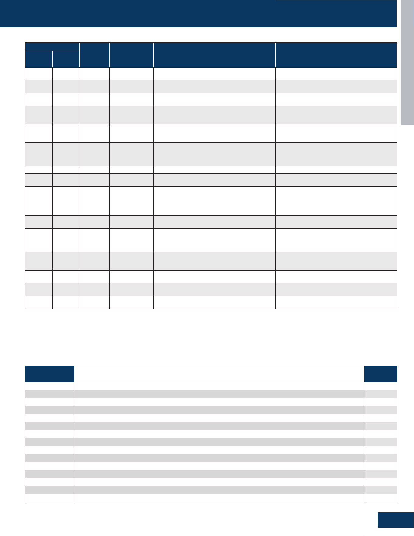
TROUBLESHOOTING & REFERENCES
F3
ENGLISH
ERROR CODES
US24LB2BEA / US30LB2BEA / US36LB2BEA / US24MB2BEA / US30MB2BEA / US36MB2BEA
LED2 FLASH TIMES
PANEL
DISPLAY
WIRED
CONTROLLER
DISPLAY
DESCRIPTION POSSIBLE CAUSES
TENS
PLACE
ONES
PLACE
0 1 E1 1
INDOOR UNIT AMBIENT TEMPERATURE SENSOR
MALFUNCTION
SENSOR DISCONNECTED, BROKEN, AT WRONG
POSITION, OR SHORT CIRCUIT.
0 2 E2 2
INDOOR UNIT PIPING TEMPERATURE SENSOR
MALFUNCTION
SENSOR DISCONNECTED, BROKEN, AT WRONG
POSITION, OR SHORT CIRCUIT.
0 4 E4 4 INDOOR PCB EEPROM WRONG
EEPROM CHIP DISCONNECTED, BROKEN,
WRONG PROGRAMMED, OR PCB BROKEN.
0 7 E7 7
ABNORMAL COMMUNICATION BETWEEN
INDOOR AND OUTDOOR UNITS
WRONG CONNECTION, WIRES DISCONNECTED,
WRONG ADDRESS SETTING OF INDOOR UNIT,
FAULTY POWER SUPPLY, OR FAULTY PCB
0 8 E8
07 FLASHING
ON THE UPPER
RIGHT CORNER
ABNORMAL COMMUNICATION BETWEEN WIRED
CONTROLLER AND INDOOR UNIT
WRONG CONNECTION, WIRED CONTROLLER
BROKEN, OR PCB FAULTY.
0 12 E12 0C DRAIN SYSTEM MALFUNCTION
PUMP MOTOR DISCONNECTED OR AT WRONG
POSITION,FLOAT SWITCH DISCONNECTED,
WRONG POSITION, OR SHORT CIRCUIT BRIDGE
DISCONNECTED
0 13 E13 0D ZERO CROSS SIGNAL WRONG ZERO CROSS SIGNAL DETECTED WRONG.
0 14 E14 0E INDOOR UNIT DC FAN MOTOR ABNORMAL
DC FAN MOTOR DISCONNECTED, FAN BROKEN,
OR CIRCUIT BROKEN
M(≥2) N(≥0) F1-F45
OUTDOOR
ERROR
CODE +20
CORRESPOND
HEX CODE
OUTDOOR UNIT ERROR
SEE CORRESPOND OUTDOOR UNIT ERROR
TROUBLESHOOTING. REMARK: F1 MEANS
OUTDOOR ERROR CODE 1, F2 MEANS OUTDOOR
ERROR CODE 2, AND SO ON.
18 6 bA BA
THE REFRIGERANT DETECTOR IS NOT
INSTALLED
NO REFRIGERANT DETECTOR IS INSTALLED
17 0 AA AA REFRIGERANT LEAKAGE
FAULT “AA” CANNOT BE CLEARED. ONLY THE
LEAKAGE CONCENTRATION DECREASES
AND THE FAULT IS TURNED TO “AB”. SEE THE
TECHNICAL MANUAL FOR ELIMINATION
17 2 Ac AC
THE COMMUNICATION OF THE REFRIGERANT
SENSOR IS FAULTY
WHEN THE AIR CONDITIONER IS RUNNING, THE
CABLE HARNESS OF THE REFRIGERANT SENSOR
FALLS OFF.
17 3 Ad AD
THE REFRIGERANT SENSOR SELF CHECK IS
FAU LT Y
THE REFRIGERANT SENSOR IS FAULTY.
17 4 AE AE REFRIGERANT SENSOR LIFE THRESHOLD
REFRIGERANT SENSOR LIFE THRESHOLD
REMINDER
17 5 AF AF THE REFRIGERANT SENSOR EXPIRES
REFRIGERANT SENSOR LIFE THRESHOLD, NEED
TO BE REPLACED
Note:
1. For more details about the outdoor unit failure, please refer to the outdoor unit troubleshooting list.
2. SW1-5 OFF: Start the refrigerant sensor function. SW1-5 ON: Disable the refrigerant sensor function.
GS24WP2BEA / GS30WB2BEA / GS36WB2BEA
OUTDOOR
LED
FAULT DESCRIPTION
INDOOR
DISPLAY
/
ROOM TEMPERATURE SENSOR FAILURE E1
/ INDOOR COIL TEMPERATURE SENSOR FAILURE E2
/ INDOOR EEPROM ERROR E4
15 COMMUNICATION FAILURE BETWEEN THE INDOOR & OUTDOOR UNIT E7
/ INDOOR FAN MOTOR FAILURE E14
21 IDU ANTI-FROSTING PROTECTION (COOLING MODE ONLY) /
21 INDOOR UNIT OVER TEMPERATURE (HEATING MODE ONLY) /
28 LACK OF REFRIGERANT OR DISCHARGING /
/ REFRIGERANT LEAKAGE FAULT >10% LFL AA
/ REFRIGERANT LEAKAGE FAULT <8% LFL Ab
/ LEAK SENSOR COMMUNICATION FAULT Ac
/ LEAKAGE SENSOR SELF-CHECK FAULT SELF-CHECK FAULT Ad
/ SENSOR REACHING END OF LIFE WARNING AE
/ LEAKAGE SENSOR END OF LIFE AF
/ DIP SWITCH ENABLED. NO SENSOR DETECTED bA
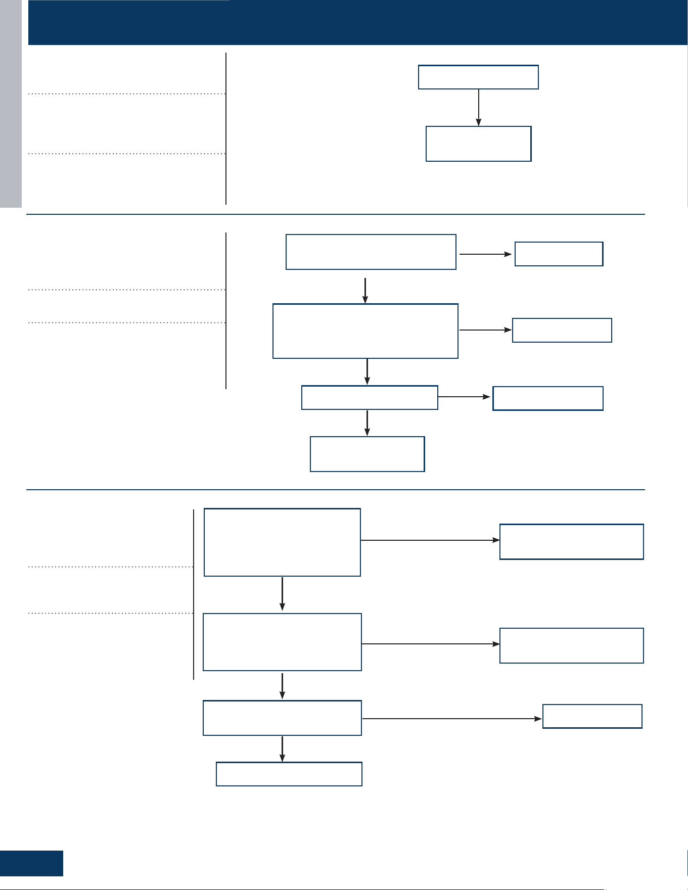
TROUBLESHOOTING & REFERENCES
F4
TROUBLESHOOTING FLOWCHARTS
ENGLISH
Code disappears after
power o/on again
Check outdoor
PCB, If faulty,
replace it.
No
Correct the wiring
Is electric box wiring correct,
and is compressor wiring rmly
connected?
Is compressor normal (compressor
coil resistor, insulation)?
Is power module normal?
Replace compressor
Replace power module
Yes
Yes
Yes
No
No
No
Solve or correct any
failures according to
relative information
Detects the wiring between
the main power terminal
block and the driver board
Main control board is bad,
replace.
Is the compressor drive module
input power normal (Test the
AC power supply voltage of the
module’s power input ACL-ACN:
normal value should between
208-230VAC)?
Check whether the CN34 output
of the MPU is 12V DC
Yes
No
No
Yes
Check whether the CN2 driver
has 12V DC input
No
Replace the DC 12V
circuit
No
Drive plate failure
[1]
Outdoor EEPROM malfunction
EEPROM communication error; EEPROM
data check error (model ID, checksum,
etc.); EEPROM data logic error (wider data
range, wrong order, etc.)
Possible Causes:
• EEPROM is bad
• Loose EEPROM wiring
[2]
Compressor Drive Module’s IPM
overcurrent or short circuit
Input over current detected by PIM’s
hardware.
Possible Causes:
• The IPM is bad
• Loose compressor wire
• The compressor is bad
[4]
Communication abnormal
between PCB and IPM
Control board can not communi-
cate with the compressor driver
module for over 4 minutes
Possible Causes:
• The communication wire is bad
• The PCB is bad
• The power module is bad
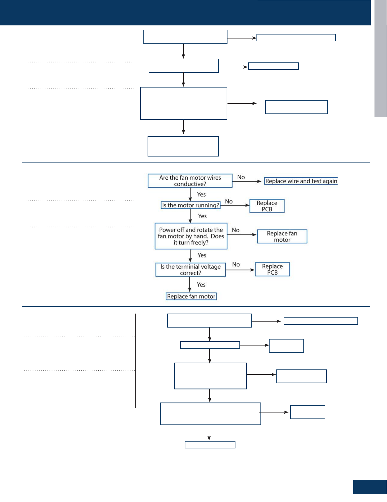
TROUBLESHOOTING & REFERENCES
F5
TROUBLESHOOTING FLOWCHARTS
ENGLISH
Correct power supply
Is power supply voltage
normal?
Is electric box wiring
correct?
Is power module voltage
between terminal P&N more
than 390V or less than 160V
during operation?
Correct the wiring
Replace power module
Yes
Yes
No
No
Check rectier, rector,
electrolytic capacitor on
inverter main circuit
No
Yes
[6]
Compressor Drive Module low or
high voltage
Driver module AC power supply voltage
over 280VAC, or driver module DC-BUS
voltage over 390VDC.
Possible Causes:
• The power supply is abnormal
• Incorrect wiring
• Power module is bad
[8]
Overheat protection for
discharge temperature
Compressor discharge temperature over
115°C. Error clears within 3 minutes if
temperature lowers below 115°C.
Possible Causes:
• The sensor is bad or xed bad
• The system is clogged
• The system lack of refrigerant
• The valve opening is wrong
Troubleshooting
Replace wire and test again
Are the fan motor wires
conductive?
Is the motor running?
Power o and rotate the
fan motor by hand. Does
it turn freely?
Is the terminial voltage correct?
Replace PCB
Replace fan motor
Replace PCB
Yes
Yes
Yes
Yes
No
No
No
No
Replace fan motor
[9]
DC fan motor fault
DC fan motor damaged, not connected,
or related circuit broken. Error status
conrms and locks if occurs 3 times within
30 minutes.
Possible Causes:
• Loose motor wiring
• The motor is bad
• The PCB is bad
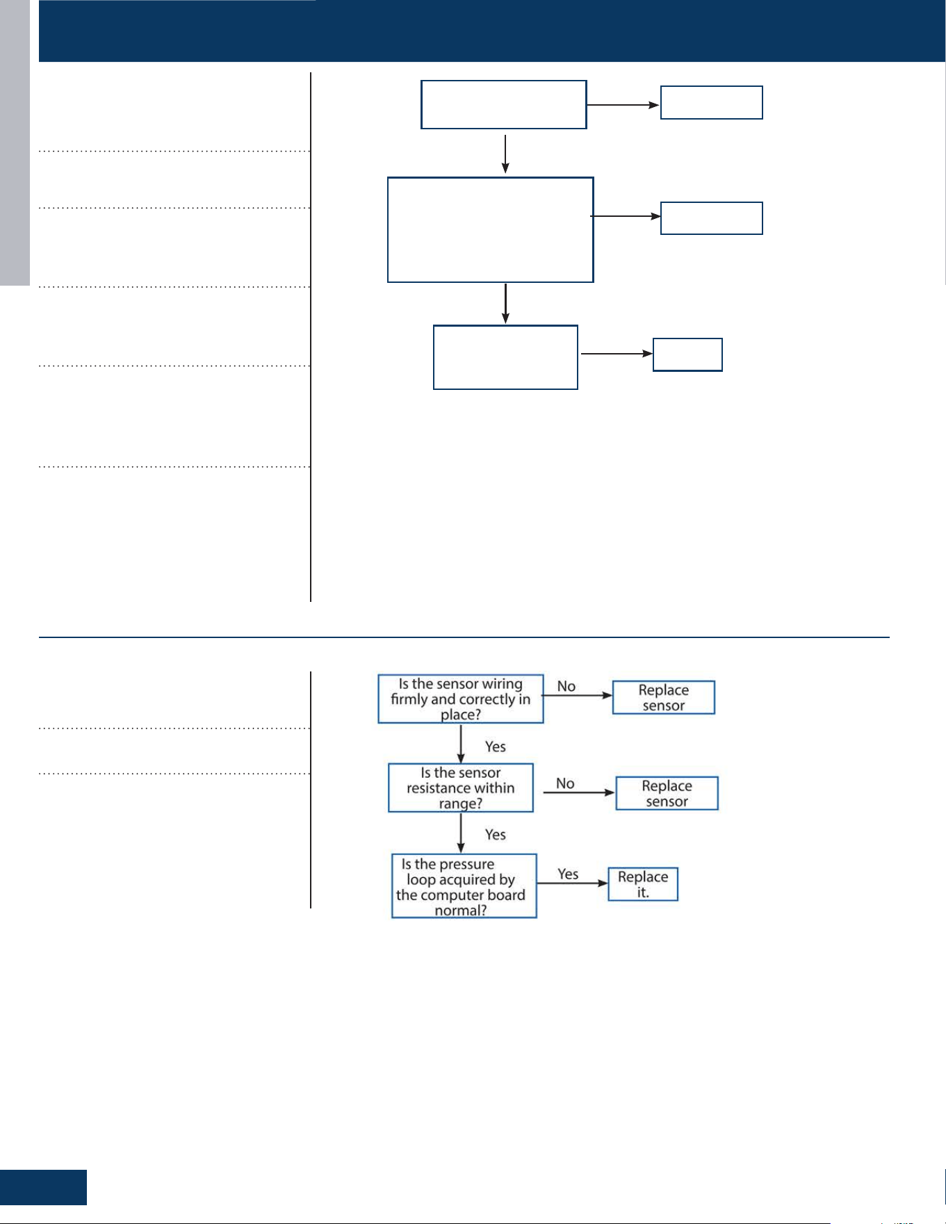
TROUBLESHOOTING & REFERENCES
F6
TROUBLESHOOTING FLOWCHARTS
ENGLISH
Replace sensor
Is the sensor wiring
rmly and correctly in
place?
Is the sensor resistance
within range?
Is the temperature
loop acquired by
the computer board
normal?
Replace sensor
Replace it.
No
No
Yes
Yes
Yes
[10]
Outdoor defrosting temp. sensor
Te abnormal
[11]
Suction temp.sensor Ts abnormal
[12]
Outdoor ambient temp. sensor Ta
abnormal
[13]
Discharging temp. sensor Td
abnormal
Sensor temperature has been detected
below or higher than expected, or has
been detected as a shorted or open circuit
(for expected temperature, refer to part
failure code)
Possible Causes:
• Bad sensor connection
• The sensor is bad
• Sensor resistance drift
• The temperature acquired by PCB is not
accurate
[15]
High pressure sensor malfunction
Has been detected as a shorted or open
circuit
Possible Causes:
• Bad sensor connection
• The sensor is bad
• Sensor resistance drift
• The pressure acquired by PCB is not
accurate
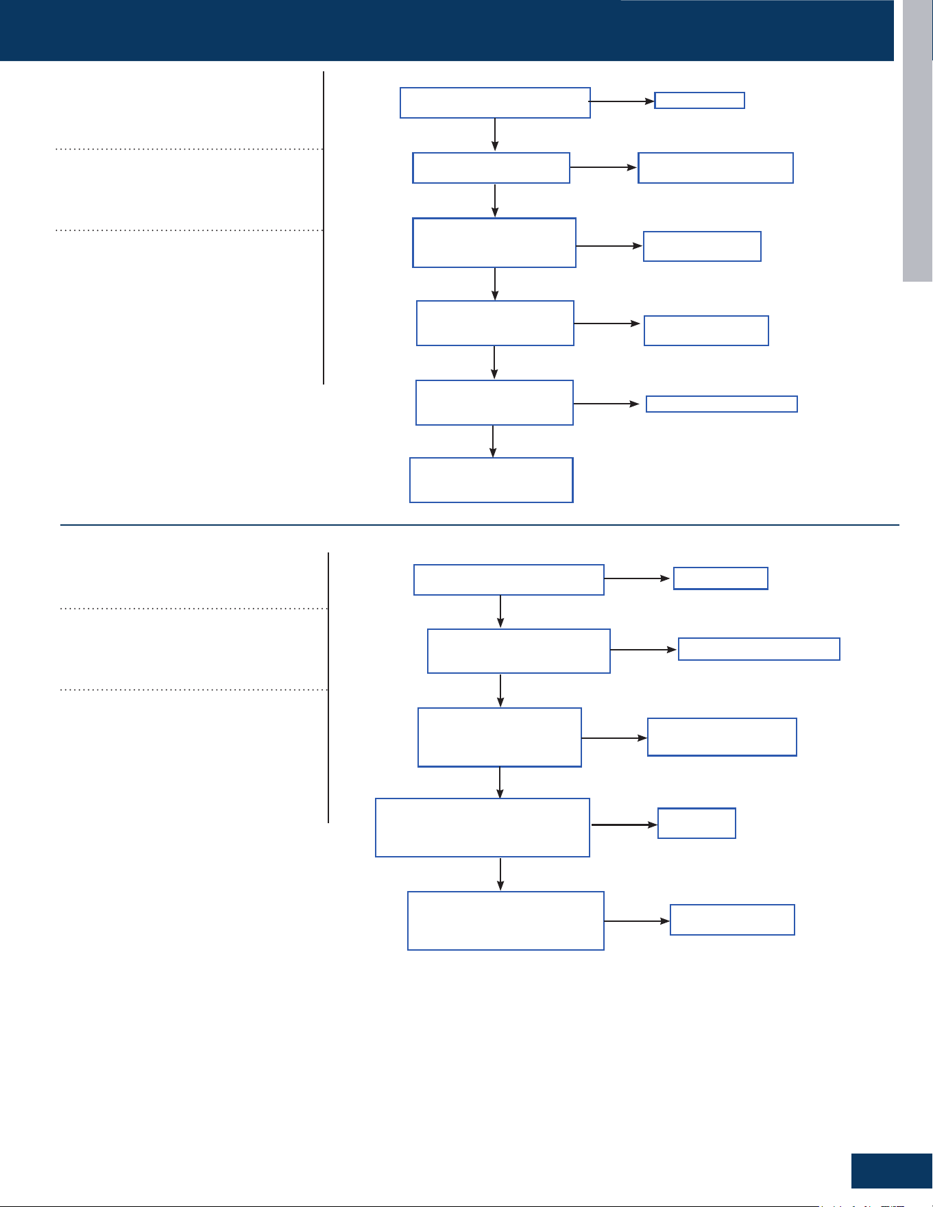
TROUBLESHOOTING & REFERENCES
F7
TROUBLESHOOTING FLOWCHARTS
ENGLISH
[16]
Lack of refrigerant or discharging
pipe blocked
Discharge & suction temperature Td-
Ts≥80°C 10 minutes after compressor
start. Error status locks if it occurs 3 times
in 1 hour.
Possible Causes:
• Wrong sensor connection
• Lack of refrigerant
• The senor is bad
• The 4-way valve is bad
• The electronic expansion valve is bad
• Out of the operating range
ERROR CODES & TROUBLESHOOTING
PAGE 32
ENGLISH
T
roubleshooting
[16] Lack of refrigerant or discharging pipe blocked
Discharge & suction temperature Td-Ts≥80°C 10
minutes after compressor start.
Possible causes:
•
Wrong sensor connection
•
Lack of refrigerant
•
The senor is bad
•
The 4-way valve is bad
•
The electronic expansion valve is bad
•
Out of the operating range
Correct wiring
Is the sensor wiring correct
and rmly connected?
Is the sy
stem leaking, or
lacking refrigerant?
Is the r
esistance of the
Td and the Tcm sensors
within range?
Repair leak and recharge
refrigerant
Replace the
sensor
Yes
No
Yes
No
Use the unit according to
the allowable operating
range of the unit.
Yes
Is there an Internal
leakage in the 4-way
valve?
No
Replace 4-way
valve
Yes
No
Adjust the valve opening
Yes
Is the electronic
expansion valve over
throttled?
[17] 4-way valve reversing failure
Indoor pipe & indoor ambient temperature
ODU TC>28°C(82F) 10 minutes after compressor started.
Possible causes:
•
The 4-way valve is bad
•
The PCB is bad
•
The 4-way valve coil connection is bad
•
The system pressure dierence is too small.
R
econnect
Is connection between the
4-way valve and PCB is good?
Is the 4-way valve coil
wiring rmly in place and
characteristics correct?
Is the system meeting
4-way valve reversing
conditions (Pd-
Ps>0.6Mpa)?
Is there air noise after 4-way
valve reverses, and the temp.
of connection pipes on 4-way
valve normal?
Correct wiring or replace
Check if the
compressor is running
Replace
PCB
Replace 4-way
valve
Yes
Yes
Yes
No
Yes
No
No
Yes
No
Is 208/230VAC Measured on
CN7(24&36K),CN5(48&60K)PCB
after 4-way valve reversing
condititons are met?
Troubleshooting
[17]
4-way valve reversing failure
Indoor pipe & indoor ambient temperature
Tm-Tai≥5°C 10 minutes after compressor
started. Error status locks if it occurs 3
times in 1 hour.
Possible Causes:
• The 4-way valve is bad
• The PCB is bad
• The 4-way valve coil connection is bad
• The system pressure dierence is too
small.
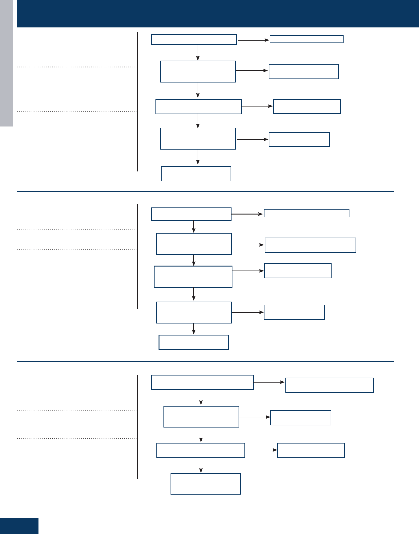
TROUBLESHOOTING & REFERENCES
F8
TROUBLESHOOTING FLOWCHARTS
ENGLISH
Correct power supply
Is supply voltage normal?
Is wire connection
between power module
and compressor correct?
Is power module is normal?
Correct the wiring
according to diagram
Replace power module
Yes
Yes
Yes
No
No
No
Is compressor normal
(compressor coil resistor,
insulation)?
Replace compressor
Yes
No
Compressor load is too
high, nd the reason
Correct power supply
Is supply voltage normal?
Is wiring between power
module and compressor
correct?
Is power module is
normal?
Correct the wiring according
to diagram
Replace power module
Yes
Yes
No
No
Compressor load too
high, nd the reason
Yes
Is compressor is normal
(compressor coil resistor,
insulation)?
No
Replace compressor
No
Correct the wiring according
to diagram
Is electric box and compressor
wiring correct and rmly in place?
Is compressor normal
(compressor coil resistor,
insulation)?
Is power module is normal?
Replace compressor
Replace power module
Yes
Yes
Yes
No
No
No
Solve or correct any
failures according to
relative information
[18]
Compressor motor
desynchronizing
Motor desynchronizing occurred. Caused
by overload, load sharply uctuating, ab-
normal compressor current sensor circuit,
or one of the inverter gate drive signals is
missing.
Possible Causes:
• The power supply is abnormal
• Incorrect compressor wiring
• The power module is bad
• The compressor is bad
• The system is overload
[24]
Compressor startup failure
Compressor start failure has been detect-
ed by driver module.
Possible Causes:
• The power supply is abnormal
• Incorrect compressor wiring
• The power module is bad
• The compressor is bad
• System overload
[25]
Input overcurrent of the drive
module
Compressor drive module input cur-
rent higher than 30A (42K&48K), or 15A
(24k),or18A (36K)
Possible Causes:
• Incorrect compressor wiring
• The power module is bad
• The compressor is bad
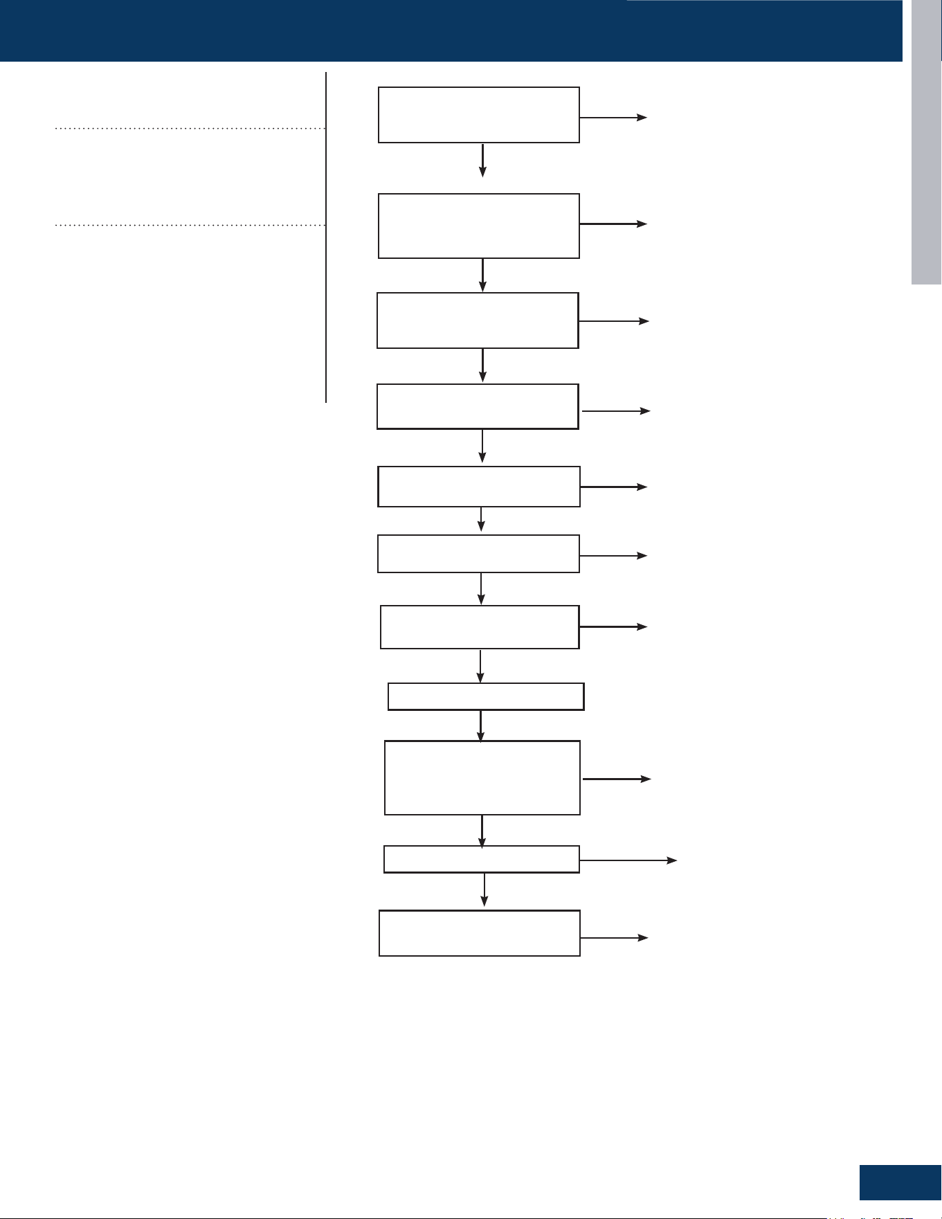
TROUBLESHOOTING & REFERENCES
F9
TROUBLESHOOTING FLOWCHARTS
ENGLISH
Reconnect
Power o, check if the
pressure switch connection
is ok
Use multimeter to check
if the high pressure witch
terminal is short circuit
Check if the EEV coil is
xed well
Check if stop valve is
open
Use the multimeter to check if
the resistance of Tc & Tm is ok
Check if the piping system is
clogged
Check if the connection pipe
is bent
The pressure is
borken,replace it.
Open the stop valve
Clean the piping system
Replace the connection pipe
Replace the sensor
Yes
Yes
No
Yes
Yes
No
No
No
No
No
Yes
No
No
Reconnect the EEV
coil
Power on
Short high pressure
switch terminal on the
PCB to check if the system
reports failure
Check if fan motor is ok
Check if the resistance
of Te and Tc is ok
The PCB is
borken,replace it.
Replace sensor
No
Yes
Yes
Yes
No
No
Replace the fan
motor
[42]
Open high pressure switch
High pressure switch: Switch circuit has
been detected open for 30 seconds (after
3 minute of compressor run time).
Opening pressure: 4.3Mpa
Closing pressure: 3.6Mpa
Possible Causes:
• Incorrect pressure switch wiring
• Abnormal system pressure
• System is clogged
• Incorrect refrigerant charge
• Bad valve
• Pressure switch is bad
• PCB is bad
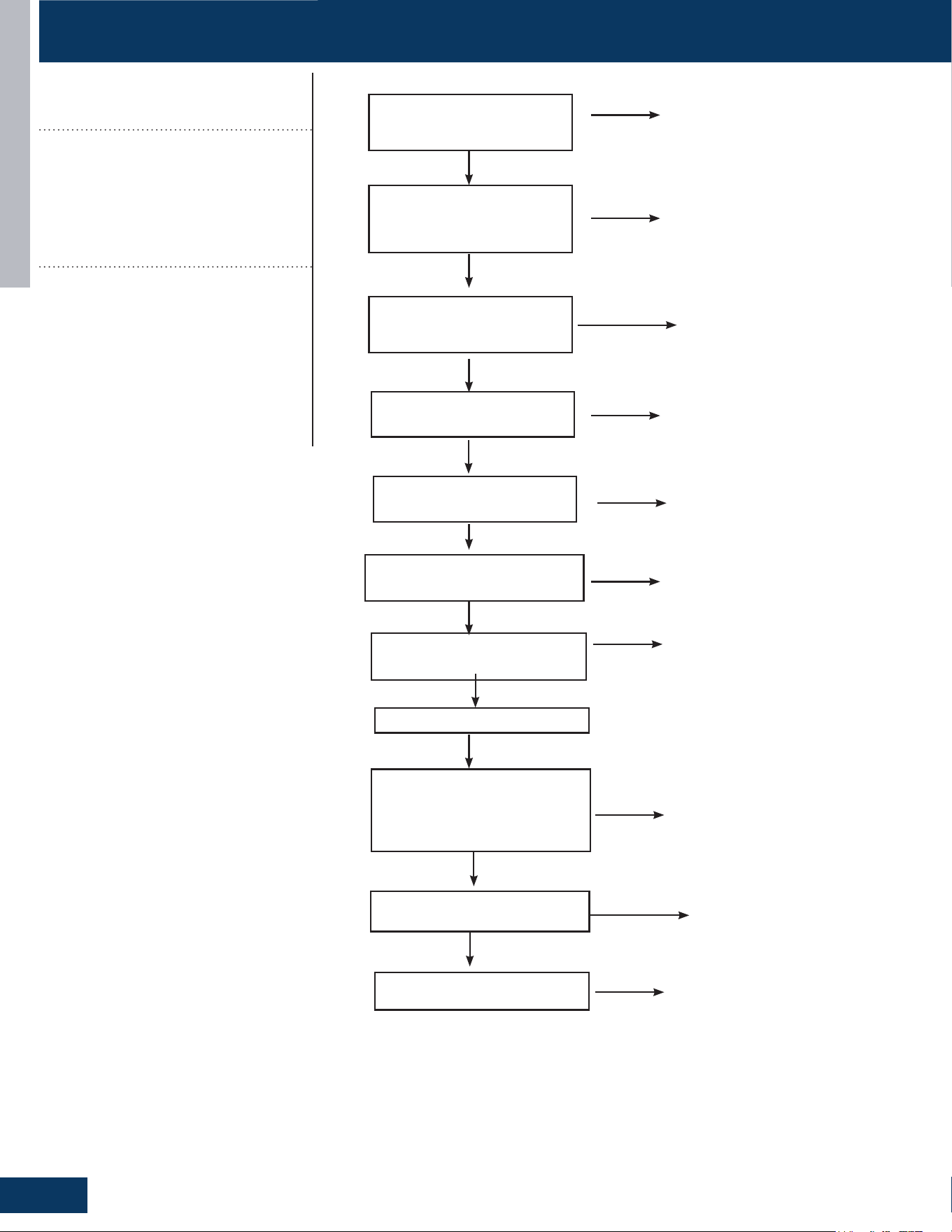
TROUBLESHOOTING & REFERENCES
F10
TROUBLESHOOTING FLOWCHARTS
ENGLISH
Reconnect
Power o, check if the
pressure switch connection
is ok
Use multimeter to check
if the low pressure witch
terminal is short circuit
Check if the EEV coil is
xed well
Check if stop valve is
open
Use the multimeter to check if the
resistance of Tc & Te &Ts is ok
Check if the piping system is
clogged
Check if the connection pipe is
bent
The pressure is
borken,replace it.
Open the stop valve
Clean the piping system
Replace the connection pipe
Replace the sensor
Yes
Yes
No
Yes
Yes
No
No
No
No
No
Yes
No
No
Reconnect the EEV
coil
Power on
Short high pressure switch
terminal on the PCB to check if
the system reports failure
Check if fan motor is ok
Check if the resistance
of Te and Toci is ok
The PCB is
borken,replace it.
Replace sensor
No
Yes
Yes
Yes
No
No
Replace the fan
motor
[43]
Open low pressure switch
Low pressure switch: Switch has been
detected open for 60 seconds (after 3
minute of compressor run time) or open
for 30 seconds during standby.
Opening pressure: 0.03Mpa
Closing pressure: 0.1Mpa
Possible Causes:
• Incorrect pressure switch wiring
• Abnormal system pressure
• System is clogged
• Incorrect refrigerant charge
• Bad valve
• Pressure switch is bad
• PCB is bad
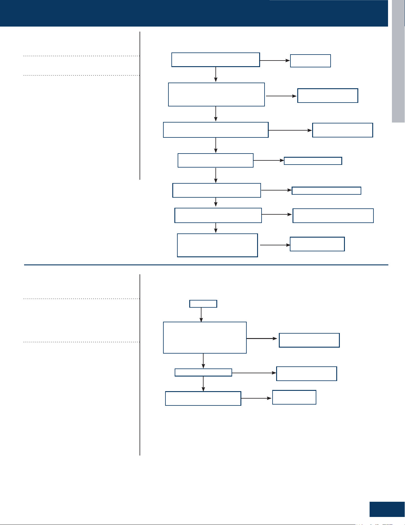
TROUBLESHOOTING & REFERENCES
F11
TROUBLESHOOTING FLOWCHARTS
ENGLISH
Reconnect
Power o. Is pressure switch
wiring connection ok?
Use multimeter to check the high
pressure switch. Is the switch
short circuited?
Is the EEV coil wiring correct and
rmly in place?
Is the stop valve is open?
Use a multimeter to check
the resistance of Tc & Tm.
Are they withing range?
Is the piping system is
clogged?
Check piping for any kinks or
damaged piping.
The pressure is bad,
replace it.
Open the stop valve
Clean the piping system
Replace the connection pipe
Replace the sensor
Yes
Yes
No
Yes
Yes
No
No
No
No
No
Yes
No
No
Reconnect the EEV
coil wiring
Power on
Short the low pressure
switch terminal on the PCB.
Does the system report a
failure?
Is the fan motor ok?
Is the resistance of Te and
Tc in range?
The PCB is bad,
replace it.
Replace sensor
No
Yes
Yes
Yes
No
No
Replace the fan
motor
[44]
High pressure detected in system
Outdoor TC sensor temperature
>65°C(149F) during cooling.
Possible Causes:
• High pressure sensor detection value is
incorrect
• Refrigerant overcharge
• Blocked liquid line piping
• The outdoor unit cannot be turned on
normally due to failure to open outdoor
heat exchanger electronic expansion
valve when heating.
• The operation environment is beyond
the allowed range.
[45]
Low pressure detected in system
The minimum temperature value of indoor
pipe Tm and outdoor Ts is lower than -45
°C during cooling mode, or minimum tem-
perature value of outdoor Tc and outdoor
Te is lower than -45 °C.
Possible Causes:
• Low pressure sensor detection value is
incorrect
• Low refrigerant charge
• System air leakage
• Blocked low pressure or liquid line piping
• The outdoor unit cannot be turned on
normally due to failure to open outdoor
heat exchanger electronic expansion
valve when heating.
• The operation environment is beyond
the allowed range.
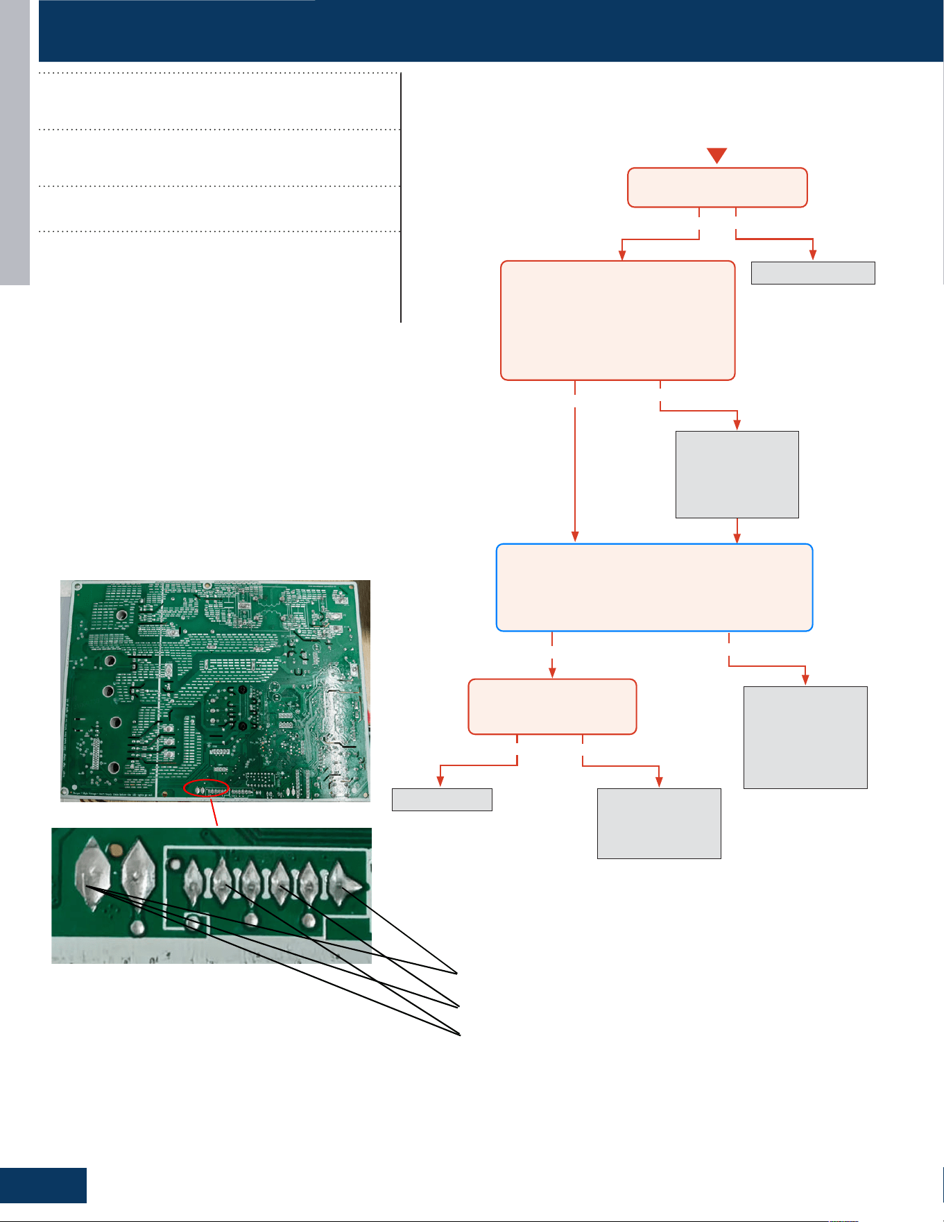
TROUBLESHOOTING & REFERENCES
F12
TROUBLESHOOTING FLOWCHARTS
ENGLISH
Yes
Yes
Yes
Yes
No
No
No
Re-seat connector
Replace sensor. Go
to next step to test
the board as well
before replacing
sensor.
No
Replace main board.
Replace sensor as
well if resistance
was incorrect in the
previous step.
Re-seat and
re-check sensor
resistance with a
different meter.
Replace sensor
Start
Is connector plugged in and
seated securely?
Disconnect power and unplug senor
connector from the board.
Check resistance across the set of
wires for the faulting sensor. Does
the resistance correspond to the
temperature located in the respective
chart?
Reconnect sensor to the board and re-apply power.
Check voltage between the two corresponding solder
joints or through the top of the Molex connector
depending on sensor confıguration.
Is the voltage ~5VDC?
Is the temperature at the
sensor out of operating
range (+/- 3%)?
5V Discharge Temperature Sensor
5V Defrost Temperature Sensor
5V Ambient Temperature Sensor
E1/LED1: No Flash
Room Temperature Sensor Failure
E2/LED1: No Flash
Indoor Coil Temperature Sensor Failure
Thermistor input is more than 4.92V or less than 0.08V
during compressor operation.
Possible Causes:
• Faulty connector connection
• Faulty thermistor
• Faulty PCB
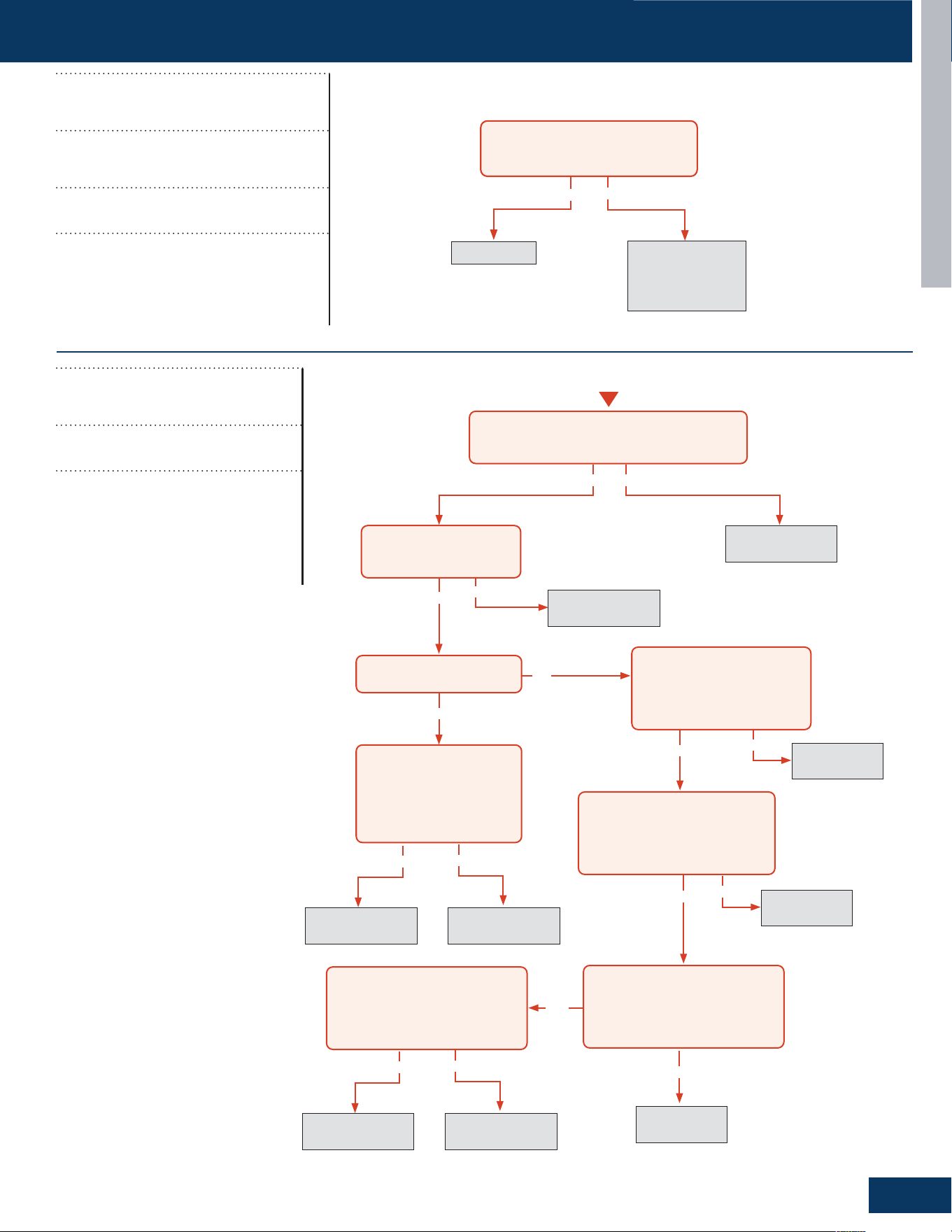
TROUBLESHOOTING & REFERENCES
F13
TROUBLESHOOTING FLOWCHARTS
ENGLISH
Yes
No
The 10-minute
reboot has
corrected the issue
Replace PCB
After 10 minutes with the power off,
the 1-flash reappears with power
turned back on?
31-5000931 Rev. 0
No
Yes
After the unit has been cut off the
power for more than 20mins
Measure the resistance between 6 and 4,
6 and 2,5 and 3,5 and 1, and the resistance
between them is roughly the same,
all less than 100 ohms
Check whether the wiring
terminal CN16 of electronic
expansion valve is
connected well.
Connect the wires well
according to the wiring
diagram.
Yes
Replace the coil of electronic
expansion valve.
Yes
Check whether the refrigerant is
leaking; if yes, please charge the
refrigerant according to the
technical specification.
No
No
Replace main PCB
1
6
5
4
3
2
E4
Indoor EEPROM Error
F12/ LED1: 1 Flash
Outdoor EEPROM Error
EEPROM data error or the EEPROM is
damaged
Possible Causes:
• Faulty EEPROM data
• Faulty EEPROM
• Faulty PCB
Yes
Yes
Yes
Yes
No
Yes No
No
Fix incoming power
supply
Replace the fan
motor
Replace the main
board.
Replace the fan
motor
Replace the
main board.
Replace the
main board.
Replace the
main board.
Start
With the power off, turn the
fan by hand. Does it move /
rotate smoothly?
Check the incoming voltage. Is it 208/230VAC (+/-
10%) between L1/L2? 104/115VAC (+/- 10%) from
L1 to GROUND and L2 to GROUND?
Re-apply power. Does the fan
come on and spin?
Measure DC voltage at fan
motor plug CN9 between
the Pin 7 (BLUE) and Pin 4
(BLACK) wire while spinning
the fan motor.
Does it generate 2~9VDC?
Measure DC voltage at fan
motor plug CN9 between Pin 1
(RED) and Pin 4 (BLACK).
Does it measure 300~380VDC
(+/-10%)?
Measure DC voltage at fan motor
plug CN9 between Pin 5 (WHITE)
and Pin 4 (BLACK).
Does it measure between
13.5-16.5VDC?
No
No
No
Yes
Replace the main
board.
Replace the fan
motor
Measure DC voltage at fan motor
plug CN9 between Pin 6 (YELLOW)
and Pin 4 (BLACK).
Does it measure between 2-6VDC?
Measure DC voltage at fan motor
plug CN9 between the Pin 7 (BLUE)
and Pin 4 (BLACK) wire while
spinning the fan motor.
Does it generate 2~9VDC?
No
Yes
No
Yes
E14
Indoor Fan Motor Failure
No rotation feedback signal detected
for 2 minutes
Possible Causes:
• Faulty fan motor
• Fan motor overheat protection
• Detection error due to faulty indoor
unit PCB
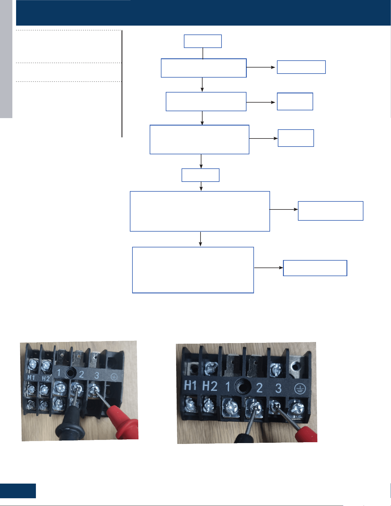
TROUBLESHOOTING & REFERENCES
F14
TROUBLESHOOTING FLOWCHARTS
ENGLISH
Replace wire
Is the communication wire is
shorted?
Is the communication wire
CN23 is disconnected?
Reconnect
Reconnect
Yes
No
No
Yes
Is the wiring connection sequence
correct according to the wiring
diagram?
No
Measure the outdoor terminal block voltage
between communication 3 and 2, and measure the
indoor terminal block between communication 3
and 2 to check. Is the communication wire ok?
Yes
Replace the
communication wire
Power o
Power on
No
Yes
Using a multimeter, measure the terminal
corresponding to the N-line voltage of CN21
from the indoor unit with the communication
failure. Is the voltage normal?
No
PCB is bad, replace PCB
outdoor terminal
indoor terminal
E7/LED1: 15 Flash
ID and OD Loss of
Communication
Outdoor PCB communication failure
• Indoor PCB communication failure
Possible Causes:
• Communication wiring disconnected
• Faulty indoor PCB
• Faulty outdoor PCB
• Faulty Outdoor Fan (may cause com-
munication signal interference)
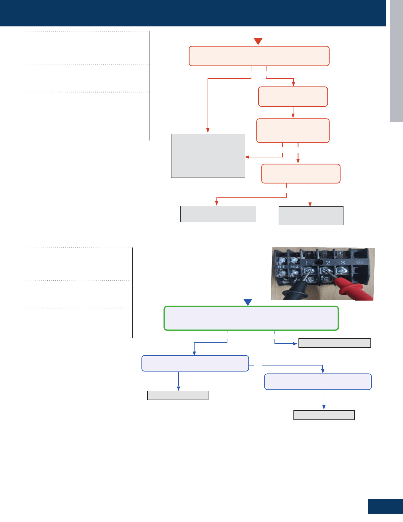
TROUBLESHOOTING & REFERENCES
F15
TROUBLESHOOTING FLOWCHARTS
ENGLISH
No
No
Yes
Momentary loss of
building power or
acceptable power
quality
Replace compressor
Replace compressor
Replace IPM
Repair or replace
wiring or
connections
When power is off for 5
min. and turned back on,
the compressor runs?
A windings or grounding check
shows issues with compressor?
There is 50-200 VAC across the U, V, and
W solder points on the IPM?
The compressor wires are on the
correct terminals, free of breaks and the
connections at both end are secure?
Yes
Yes
Yes
No
No
No
No
Yes
Yes No
Start
Cycle power to the outdoor unit. Turn system on via
remote control. Does the error occur immediately?
Allow system to run until
error code is displayed
Troubleshoot the pipe
temperature sensor and
temperature monitoring
circuit of the indoor main
board. Replace components
found faulty.
Service the fan or clean
fılters as necessary.
Measure system charge level
and adjust as required.
Yes
Is the pipe at the location of
the pipe temperature sensor
under 149
O
F?
Is fan motor running properly
and fılters unobstructed?
LED1: 21 Flash
Indoor Unit Over Temperature
(Heating Mode Only)
Activated when the temperature being sensed
by the heat exchanger pipe sensor rises above
149
O
F twice in 30 minutes.
Possible Causes:
• Faulty electronic expansion valve
• Dirty heat exchanger
• Faulty heat-exchange sensor
• Refrigerant undercharge
Note: this is a resetting fault that will
not lockout operation.
No
Ye s
No
Refilling refrigerant
Start
Measure the current between 1/2
Is it 0.6A - 2.5A?
Replace the Coil
Ye s
Replace the PCB
Check the coil leakage
Check the coil leakage
Check the discharge refrigerant
Ye s
No
Start
Measure whether the detection of indoor unit coil temperature
sensor is accurate?
clen up the stuffs
Ye s
Replace the coil temperature
sensor
Check if there is any stuffs blocking
the air inlet
LED1: 28 Flash
Lack of Refrigerant or
Discharging
Compressor operation frequency
more than 46Hz,the current between
0.6A and 2.5A
Possible Causes:
• Coil leakage
• Discharge refrigerant
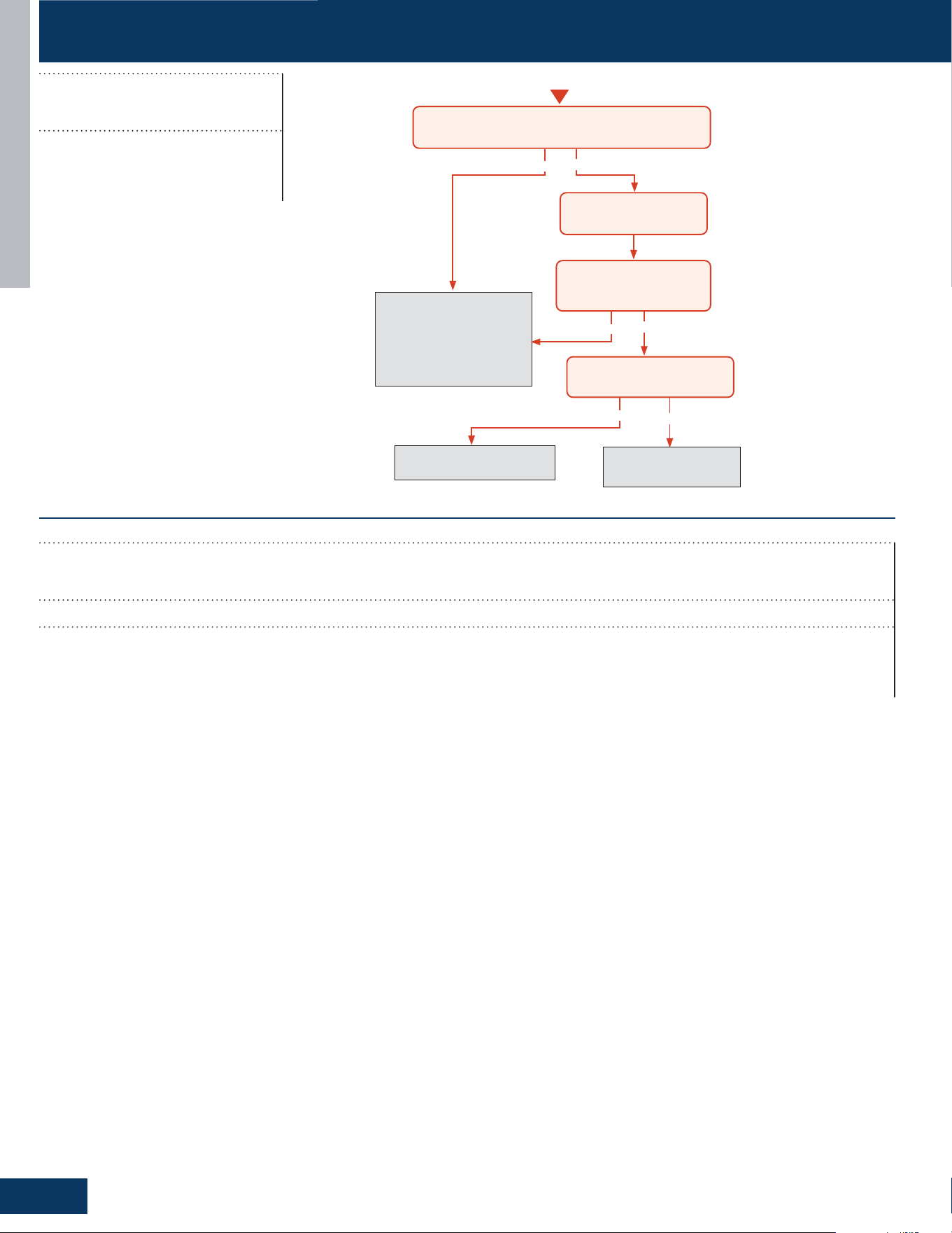
TROUBLESHOOTING & REFERENCES
F16
TROUBLESHOOTING FLOWCHARTS
ENGLISH
E22/LED1: 21 Flash
IDU Anti-Frosting Protection
Possible Causes:
• Coil temperature sensor
• IDU air inlet blockage
F27/LED1: 21 Flash
Compressor Current Sampling Circuit Fault
It is compressor block fault, the compressor will not work when this fault happen. It also can be self recovery when this fault happens.
Possible Causes:
• Ambient temperature is too low
• Compressor damage
ENGLI SH
TROUBLESHOOTING FLOWCHARTS
C- 9
TROUBLESHOOTING & REFERENCE
Error Code
(Indoor)
E22/ LED1: 21 Flash
Indoor Unit Anti
-
frosting
protection
(cooling Mode Only)
Det ect ion Conditions:
• Activated when the temperature being sensed by
the heat exchanger pipe sensor rises under 36
O
F
twice in 30 minutes.
Possi bl e Causes:
• Faulty electronic expansion valve
• Dirty heat exchanger
• Faulty heat-exchange sensor
• Refrigerant undercharge
Note: this is a resetting fault that will not lockout operation.
No
No
Yes
Yes No
Start
Cycle power to the outdoor unit. Turn system on via
remote control. Does the error occur immediately?
Allow system to run until
error code is displayed
Troubleshoot the pipe
temperature sensor and
temperature monitoring
circuit of the indoor main
board. Replace components
found faulty.
Service the fan or clean
fılters as necessary.
Measure system charge level
and adjust as required.
Yes
Is the pipe at the location of
the pipe temperature sensor
under 36
O
F?
Is fan motor running properly
and fılters unobstructed?
Troubleshooting
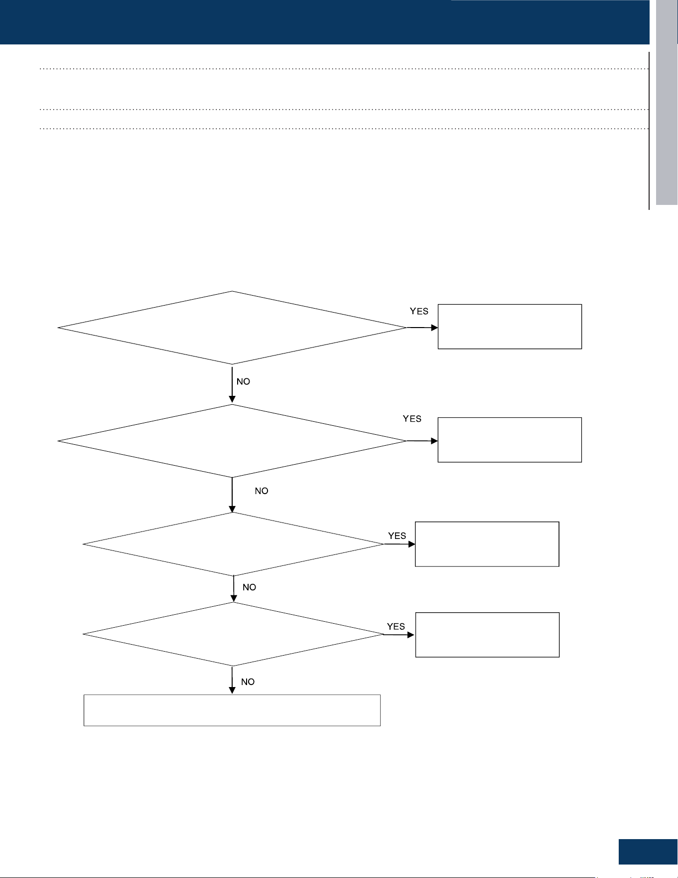
TROUBLESHOOTING & REFERENCES
F17
TROUBLESHOOTING FLOWCHARTS
ENGLISH
Check if the wiring harness is damaged
Replace the wiring harness
Replace the leakage sensor
Check if the wiring harness has poor contact
Reconnect the wiring harness
Check if the PCB is damaged
Replace the PCB
Connect the leakage sensor
Check if the leakage sensor is disconnected with Indoor PCB
Error Codes (Indoor)
bA
DIP Switch Enabled, No Sensor Detected
DIP Switch Enabled, No Sensor Detected
Possible Causes:
• Loose wiring terminals
• Damaged wiring harness
• The leakage sensor is not connected
• PCB damage
* Caution
Be sure to turn o power switch before connect or disconnect connector, or else parts damage may be occurred.
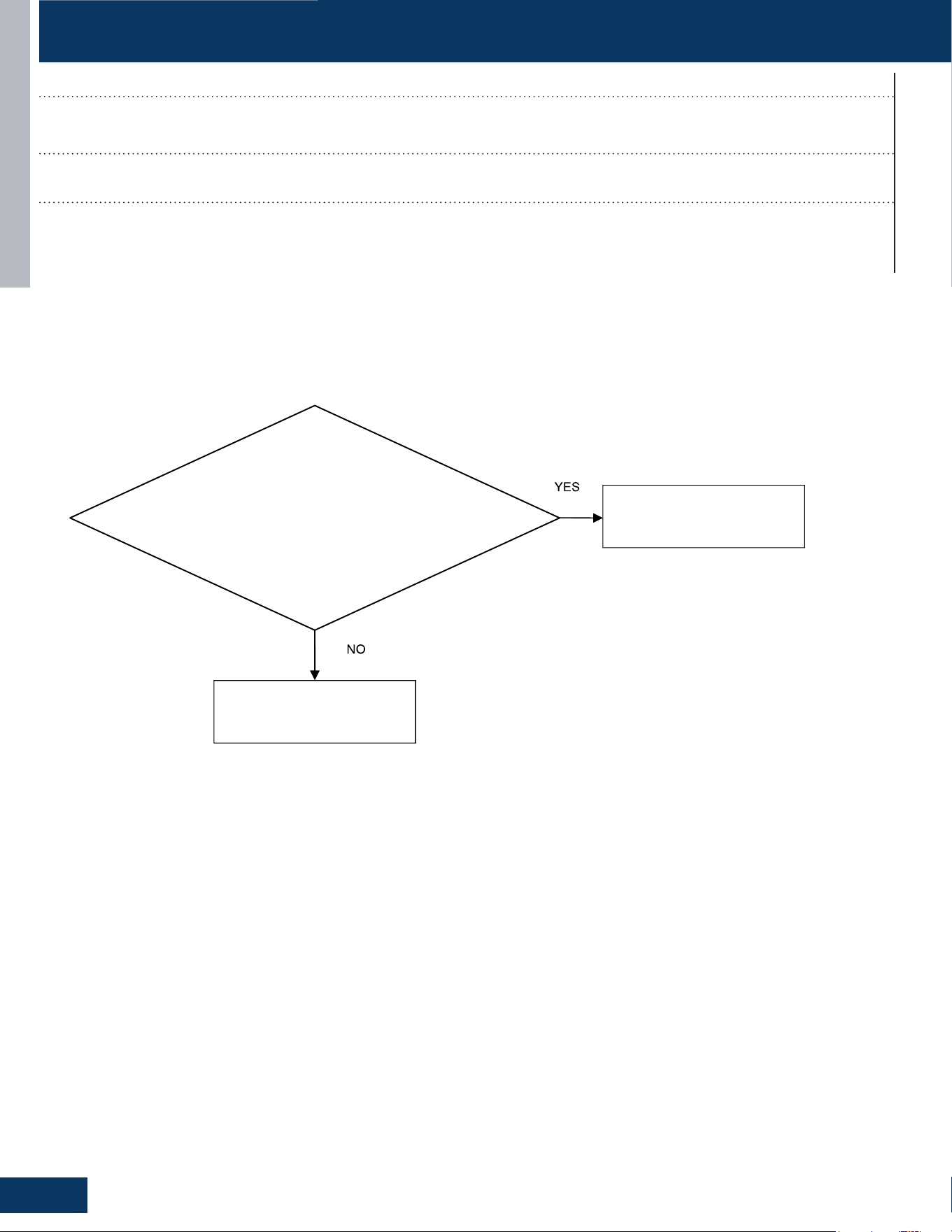
TROUBLESHOOTING & REFERENCES
F18
TROUBLESHOOTING FLOWCHARTS
ENGLISH
Check for refrigerant leakage
Replace the indoor unit or weld
the pipeline
Replace the leakage sensor
Error Codes (Indoor)
AA and Ab
Refrigerant Leakage Fault
• AA: Refrigerant concentration over 10% LFL
• Ab: AA display after 5 minutes and refrigerant concentration of less than 8% LFL detected
Possible Causes:
• Pipe cracking
• The union nut is not secured
* Caution
Be sure to turn o power switch before connect or disconnect connector, or else parts damage may be occurred.

TROUBLESHOOTING & REFERENCES
F19
TROUBLESHOOTING FLOWCHARTS
ENGLISH
Check if the wiring harness is damaged
Replace the wiring harness
Replace the leakage sensor
Check if the wiring harness has poor contact
Reconnect the wiring harness
Check if the PCB is damaged
Replace the PCB
Error Codes (Indoor)
Ac
Leakage Sensor Communication Fault
The communication between the leakage sensor and the PCB is faulty
Possible Causes:
• Loose wiring terminals
• Damaged wiring harness
• PCB damage
* Caution
Be sure to turn o power switch before connect or disconnect connector, or else parts damage may be occurred.

TROUBLESHOOTING & REFERENCES
F20
TROUBLESHOOTING FLOWCHARTS
ENGLISH
Check if the sensor itself is damaged
Replace the leakage sensor
Replace the leakage sensor
Measure whether the sensor voltage is normal
Replace the PCB or leakage sensor
Check the temperature of the usage environment
Normal temperature range -35 to 80 degrees
Celsius
Error Codes (Indoor)
Ad
Leakage Sensor Self-Check Fault
Leakage sensor self-test failed
Possible Causes:
• Power supply overvoltage and undervoltage (5VDC)
• The temperature value detected by the leakage sensor exceeds the limit value
• Internal sensor error
* Caution
Be sure to turn o power switch before connect or disconnect connector, or else parts damage may be occurred.
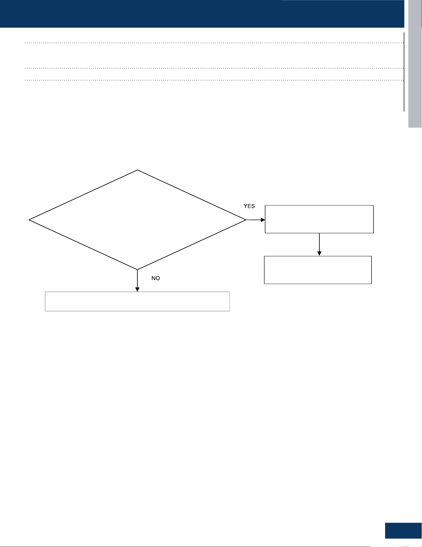
TROUBLESHOOTING & REFERENCES
F21
TROUBLESHOOTING FLOWCHARTS
ENGLISH
Check the actual usage time of the sensor
Actual usage time reaches 14.5 years
The unit power cycle
Replace the leakage sensor
Error Codes (Indoor)
AE
Leakage Sensor Reaching-End-of-Life Warning
The sensor is 6 months away from the end of its life
Possible Causes:
• The sensor approaching the end of life
• End of life counting error of sensor
* Caution
Be sure to turn o power switch before connect or disconnect connector, or else parts damage may be occurred.

TROUBLESHOOTING & REFERENCES
F22
TROUBLESHOOTING FLOWCHARTS
ENGLISH
Check the actual usage time of the sensor
Actual usage time reaches 15 years
The unit power cycle
Replace the leakage sensor
Error Codes (Indoor)
AF
Leakage Sensor End- Of- Life
The sensors have reached the end of life
Possible Causes:
• The sensor approaching the end of life
• End of life counting error of sensor
* Caution
Be sure to turn o power switch before connect or disconnect connector, or else parts damage may be occurred.

TROUBLESHOOTING & REFERENCES
F23
ENGLISH
SENSOR RESISTANCE TABLES
B25/50=3700K±3% R25=10KΩ±3%
Temp Resistance(KΩ) Temp Resistance(KΩ)
(°C) Rmax R (t) Normal Rmin (°C) Rmax R (t) Normal Rmin
-40 246.890 229.239 211.587 11 18.864 18.135 17.406
-39 233.754 217.183 200.612 12 18.039 17.354 16.669
-38 221.368 205.809 190.250 13 17.254 16.611 15.968
-37 209.686 195.075 180.464 14 16.507 15.903 15.299
-36 198.665 184.942 171.219 15 15.797 15.229 14.661
-35 188.265 175.375 162.485 16 15.120 14.587 14.054
-34 178.449 166.339 154.230 17 14.476 13.975 13.474
-33 169.181 157.803 146.426 18 13.862 13.392 12.922
-32 160.429 149.738 139.046 19 13.277 12.836 12.395
-31 152.162 142.114 132.067 20 12.720 12.306 11.892
-30 144.350 134.907 125.464 21 12.189 11.801 11.413
-29 136.519 127.675 118.831 22 11.683 11.319 10.955
-28 129.381 121.081 112.781 23 11.200 10.858 10.516
-27 122.638 114.849 107.060 24 10.739 10.419 10.099
-26 116.268 108.958 101.648 25 10.300 10.000 9.700
-25
110.249 103.388 96.527 26 9.894 9.600 9.306
-24 104.563 98.123 91.683 27 9.505 9.217 8.929
-23 99.190 93.144 87.098 28 9.134 8.852 8.570
-22 94.111 88.435 82.759 29 8.779 8.503 8.227
-21 89.311 83.982 78.653 30 8.441 8.170 7.899
-20 84.518 79.529 74.540 31 8.116 7.851 7.586
-19 80.484 75.785 71.086 32 7.805 7.546 7.287
-18 76.428 72.015 67.602 33 7.509 7.255 7.001
-17 72.591 68.447 64.303 34 7.225 6.976 6.727
-16 68.963 65.071 61.179 35 6.953 6.710 6.467
-15 65.530 61.874 58.218 36 6.692 6.454 6.216
-14 62.283 58.848 55.413 37 6.443 6.210 5.977
-13 59.210 55.983 52.756 38 6.204 5.976 5.748
-12 56.300 53.269 50.238 39 5.976 5.753 5.530
-11 53.547 50.699 47.851 40 5.756 5.538 5.320
-10 50.940 48.264 45.588 41 5.546 5.333 5.120
-9 48.472 45.957 43.442 42 5.345 5.136
4.927
-8 46.134 43.770 41.406 43 5.151 4.947 4.743
-7 43.918 41.697 39.476 44 4.967 4.767 4.567
-6 41.819 39.731 37.643 45 4.788 4.593 4.398
-5 39.830 37.868 35.906 46 4.618 4.427 4.236
-4 37.944 36.100 34.256 47 4.455 4.268 4.081
-3 36.157 34.423 32.689 48 4.298 4.115 3.932
-2 34.462 32.832 31.202 49 4.147 3.968 3.789
-1 32.854 31.322 29.790 50 4.004 3.829 3.654
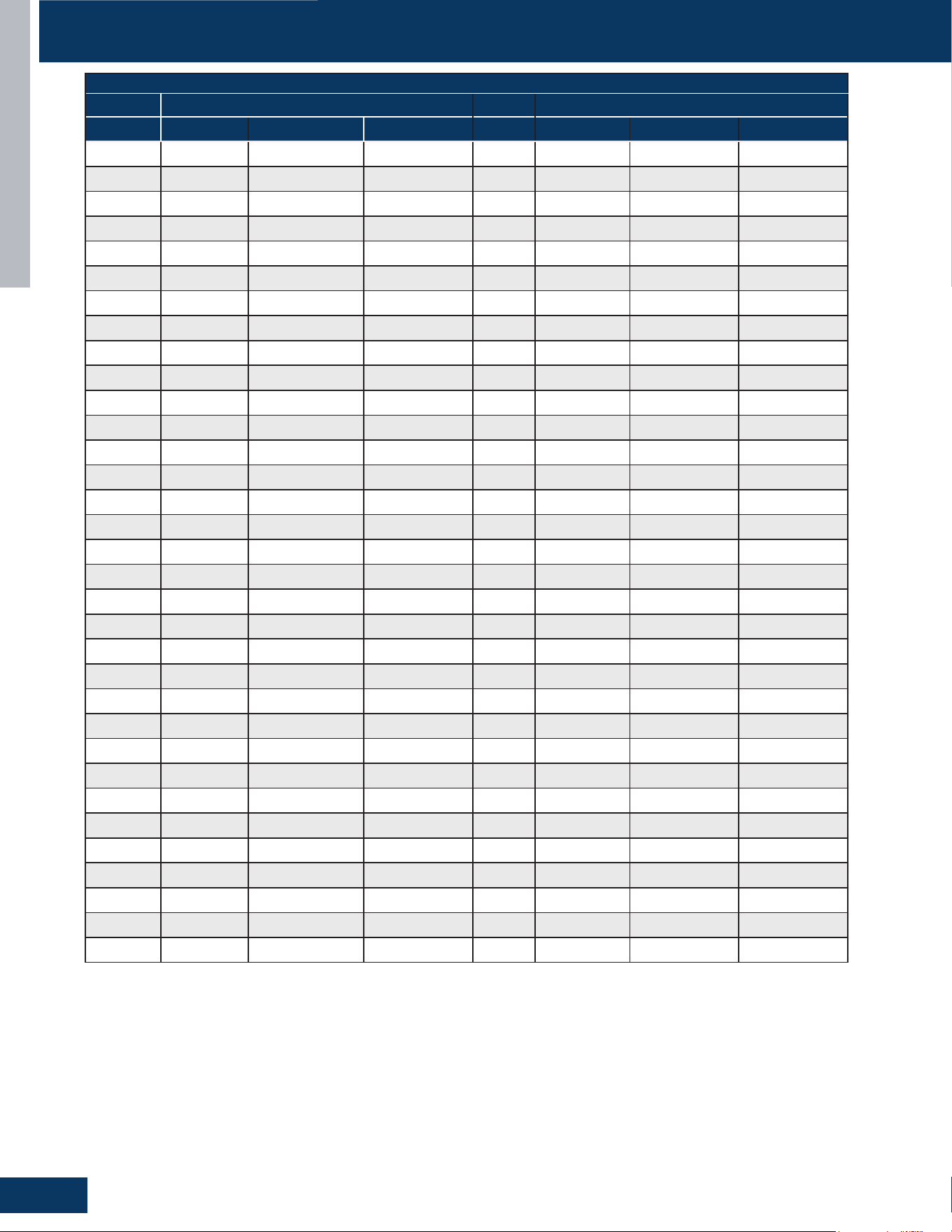
TROUBLESHOOTING & REFERENCES
F24
ENGLISH
SENSOR RESISTANCE TABLES
B25/50=3700K±3% R25=10KΩ±3%
Temp Resistance(KΩ) Temp Resistance(KΩ)
(°C) Rmax R (t) Normal Rmin (°C) Rmax R (t) Normal Rmin
0 31.362 29.920 28.478 51 3.863 3.692 3.521
1 29.881 28.527 27.173 52 3.729 3.562 3.395
2 28.507 27.234 25.961 53 3.601 3.438 3.275
3 27.202 26.006 24.810 54 3.478 3.318 3.158
4 25.965 24.840 23.715 55 3.359 3.203 3.047
5 24.788 23.731 22.674 56 3.246 3.093 2.940
6 23.672 22.678 21.684 57 3.136 2.987 2.838
7 22.610 21.676 20.742 58 3.031 2.885 2.739
8 21.601 20.723 19.845 59 2.930 2.787 2.644
9 20.642 19.817 18.992 60 2.833 2.693 2.553
10 19.730 18.955 18.180 61 2.739 2.602 2.465
62 2.649 2.515 2.381 84 1.321 1.238 1.155
63 2.562 2.431 2.300 85 1.281 1.200 1.119
64 2.478 2.350 2.222 86 1.244 1.165 1.086
65 2.398 2.273 2.148 87 1.209 1.131 1.053
66
2.320 2.198 2.076 88 1.173 1.097 1.021
67 2.246 2.126 2.006 89 1.140 1.065 0.990
68 2.174 2.057 1.940 90 1.107 1.034 0.961
69 2.104 1.990 1.876 91 1.076 1.004 0.932
70 2.038 1.926 1.814 92 1.045 0.975 0.905
71 1.974 1.864 1.754 93 1.016 0.947 0.878
72 1.912 1.805 1.698 94 0.987 0.920 0.853
73 1.853 1.748 1.643 95 0.960 0.894 0.828
74 1.795 1.692 1.589 96 0.934 0.869 0.804
75 1.739 1.639 1.539 97 0.907 0.844 0.781
76 1.686 1.588 1.490 98 0.883 0.821 0.759
77 1.634 1.538 1.442 99 0.859 0.798 0.737
78 1.585 1.491 1.397 100 0.836 0.776 0.716
79 1.537 1.445 1.353 101 0.814 0.755 0.696
80 1.490 1.400 1.310 102 0.791 0.734 0.677
81 1.445 1.357 1.269 103 0.771 0.715 0.659
82 1.402 1.316 1.230 104 0.750 0.695
0.640
83 1.361 1.276 1.191 105 0.731 0.677 0.623
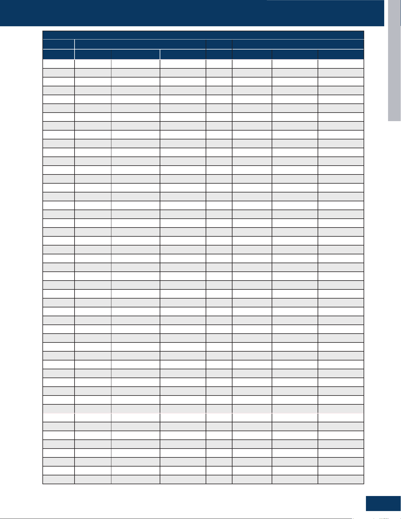
TROUBLESHOOTING & REFERENCES
F25
ENGLISH
SENSOR RESISTANCE TABLES
B25/80=4450K±3% R80=50KΩ±3%
Temp Resistance(KΩ) Temp Resistance(KΩ)
(°C) Rmax R (t) Normal Rmin (°C) Rmax R (t) Normal Rmin
-40 23982.342 21280.977 18579.613 11 1126.419 1041.293 956.167
-39 22397.462 19890.917 17384.372 12 1067.463 987.477 907.491
-38 20925.744 18599.155 16272.567 13 1011.977 936.799 861.621
-37 19558.506 17398.211 15237.916 14 959.732 889.052 818.372
-36 18287.777 16281.212 14274.647 15 910.510 844.042 777.574
-35 17106.237 15241.843 13377.450 16 864.114 801.590 739.066
-34 16007.159 14274.298 12541.437 17 820.361 761.533 702.705
-33 14984.359 13373.234 11762.109 18 779.081 723.717 668.353
-32 14032.148 12533.735 11035.322 19 740.117 688.001 635.885
-31 13145.291 11751.273 10357.255 20 703.323 654.254 605.185
-30 12318.968 11021.678 9724.388 21 668.565 622.355 576.145
-29 11551.311 10343.407 9135.504 22 635.715 592.189 548.663
-28 10835.229 9710.234 8585.239 23 604.657 563.651 522.645
-27 10167.003 9118.935 8070.867 24 575.282 536.644 498.006
-26 9543.200 8566.532 7589.865 25 547.490 511.076 474.662
-25
8960.652 8050.276 7139.901 26 521.186 486.862 452.538
-24 8416.430 7567.624 6718.818 27 496.281 463.922 431.563
-23 7907.828 7116.224 6324.620 28 472.693 442.182 411.671
-22 7432.345 6693.901 5955.457 29 450.344 421.572 392.800
-21 6987.666 6298.642 5609.618 30 429.165 402.028 374.891
-20 6571.650 5928.583 5285.516 31 409.087 383.489 357.891
-19 6187.164 5586.374 4985.585 32 390.047 365.898 341.749
-18 5826.712 5265.313 4703.915 33 371.986 349.201 326.416
-17 5488.692 4964.004 4439.315 34 354.850 333.349 311.848
-16 5171.616 4681.148 4190.680 35 338.586 318.295 298.004
-15 4874.100 4415.539 3956.978 36 323.147 303.995 284.843
-14 4594.858 4166.054 3737.249 37 308.485 290.407 272.329
-13 4332.694 3931.647 3530.600 38 294.559 277.493 260.427
-12 4086.494 3711.346 3336.198 39 281.328 265.216 249.104
-11 3855.222 3504.244 3153.266 40 268.753 253.541 238.329
-10 3637.915 3309.498 2981.082 41 256.801 242.437 228.073
-9 3433.673 3126.321 2818.969 42 245.438 231.873 218.308
-8 3241.661 2953.980 2666.299 43 234.630 221.820 209.010
-7 3061.098 2791.790 2522.482 44 224.350 212.252 200.154
-6 2891.257 2639.114 2386.971 45 214.569 203.142 191.715
-5 2731.460 2495.357 2259.253 46 205.260 194.467 183.674
-4 2581.076 2359.962 2138.848 47 196.399 186.204 176.009
-3 2439.514 2232.412 2025.310 48 187.963 178.333 168.703
-2 2306.222 2112.221 1918.220 49 179.929 170.832 161.735
-1 2180.688 1998.938 1817.187 50 172.275 163.682 155.089
0 2094.972 1921.993 1749.014 51 164.984 156.866 148.748
1 1975.099 1813.265 1651.431 52 158.036 150.367 142.698
2 1863.127 1711.646 1560.165 53 151.412 144.168 136.924
3 1758.449 1616.593 1474.737 54 145.099 138.255 131.411
4 1660.513 1527.611 1394.709 55 139.078 132.613 126.148
5 1568.817 1444.250 1319.683 56 133.336 127.229 121.122
6 1482.897 1366.096 1249.295 57 127.858 122.089 116.320
7 1402.336 1292.773 1183.210 58 122.630 117.181 111.732
TROUBLESHOOTING & REFERENCES
F26
ENGLISH
SENSOR RESISTANCE TABLES
B25/80=4450K±3% R80=50KΩ±3%
Temp Resistance(KΩ) Temp Resistance(KΩ)
(°C) Rmax R (t) Normal Rmin (°C) Rmax R (t) Normal Rmin
8 1326.746 1223.935 1121.124 59 117.641 112.494 107.347
9 1255.774 1159.265 1062.756 60 112.879 108.018 103.157
10 1189.098 1098.474 1007.850 61 108.332 103.741 99.150
62 103.989 99.654 95.319 107 20.667 19.720 18.773
63 99.841 95.748 91.655 108 20.020 19.091 18.162
64 95.879 92.014 88.149 109 19.397 18.485 17.573
65 92.091 88.443 84.795 110 18.795 17.900 17.005
66 88.472 85.028 81.584 111 18.215 17.337 16.459
67 85.011 81.761 78.511 112 17.655 16.793 15.931
68 81.703 78.636 75.569 113 17.114 16.268 15.422
69 78.538 75.645 72.752 114 16.593 15.763 14.933
70 75.510 72.781 70.052 115 16.090 15.275 14.460
71 72.614 70.040 67.466 116 15.603 14.804 14.005
72 69.842 67.415 64.988 117 15.133 14.349 13.565
73 67.189 64.901 62.613 118 14.681 13.911 13.141
74
64.649 62.493 60.337 119 14.243 13.488 12.733
75 62.216 60.185 58.154 120 13.821 13.080 12.339
76 59.886 57.973 56.060 121 13.412 12.685 11.958
77 57.653 55.852 54.051 122 13.019 12.305 11.591
78 55.515 53.820 52.125 123 12.638 11.938 11.238
79 53.465 51.870 50.275 124 12.271 11.584 10.897
80 51.500 50.000 48.500 125 11.917 11.242 10.567
81 49.684 48.206 46.728 126 11.573 10.911 10.249
82 47.940 46.484 45.028 127 11.243 10.593 9.943
83 46.267 44.832 43.397 128 10.923 10.285 9.647
84 44.659 43.246 41.833 129 10.614 9.988 9.362
85 43.114 41.723 40.332 130 10.315 9.701 9.087
86 41.629 40.260 38.891 131 10.028 9.425 8.822
87 40.203 38.856 37.509 132 9.750 9.158 8.566
88 38.831 37.506 36.181 133 9.481 8.900 8.319
89 37.513 36.209 34.905 134 9.222 8.651 8.080
90 36.244 34.962 33.680 135 8.972 8.411 7.850
91 35.025 33.764 32.503 136 8.731 8.180 7.629
92 33.851 32.612 31.373 137 8.498 7.957 7.416
93 32.722 31.504 30.286 138 8.273 7.741 7.209
94 31.636 30.439 29.242 139 8.055 7.533 7.011
95 30.590 29.413 28.236 140 7.846 7.333 6.820
96 29.583 28.427 27.271 141 7.628 7.125 6.621
97 28.614 27.478 26.342 142 7.417 6.923 6.429
98 27.680 26.564 25.448 143 7.213 6.728 6.243
99 26.781 25.685 24.589 144 7.014 6.538 6.062
100 25.914 24.838 23.762 145 6.822 6.355 5.888
101 25.080 24.023 22.966 146 6.636 6.178 5.719
102 24.275 23.237 22.199 147 6.455 6.006 5.556
103 23.500 22.481 21.462 148 6.280 5.839 5.398
104 22.753 21.752 20.751 149 6.111 5.678 5.244
105 22.031 21.049 20.067 150 5.946 5.521 5.096
106 21.336 20.372 19.408

[This page intentionally left blank.]
Rev. 10-16-25
©Copyright 2025 GE Appliances, a Haier Company.
Our continued commitment to quality products may
mean a change in specications without notice.
Ductless Technical Support
Phone: 866.814.3633
Email: HVACSupport@GEAppliances.com
Online: GEAppliancesAirAndWater.com