

Active Junction Box Power-DMX-Ethernet to PDE
Passive Junction Box Power-DMX-Ethernet to PDE
Break-In Cable Power-DMX-Ethernet to PDE
Break-Out Cable PDE to Power-DMX-Ethernet
User Guide

Table of contents
Dimensions ................................................................................................................. 3
Safety information....................................................................................................... 5
Précautions d'emploi................................................................................................... 7
Sicherheitshinweise .................................................................................................... 9
Introduction ............................................................................................................... 11
Before using the product for the first time..........................................................................11
Active Junction Box overview ................................................................................... 12
Passive Junction Box overview ................................................................................ 13
Break-In Cable overview........................................................................................... 14
Break-Out Cable overview........................................................................................ 14
Physical installation (Junction Boxes)....................................................................... 15
Product location ................................................................................................................15
Mounting the junction box .................................................................................................15
AC power and data connection to Active Junction Box............................................ 16
Safety limits for connecting devices ..................................................................................16
AC power connection to Junction Box...............................................................................16
Data connection to Active Junction Box using DMX512....................................................17
Data connection to Active Junction Box using Art-Net or sACN........................................18
Data connection to Active Junction Box using P3 .............................................................19
AC power and data connection to Passive Junction Box or Break-In Cable............ 20
Safety limits for connecting devices ..................................................................................20
AC power connection to Junction Box or Break-In Cable..................................................20
Data connection to Passive Junction Box or Break-In Cable using DMX512....................21
Data connection to Passive Junction Box or Break-In Cable using Art-Net or sACN ........22
Data connection to Passive Junction Box or Break-In Cable using P3 .............................23
AC power and data connection using Break-Out Cable........................................... 24
System Setup............................................................................................................ 25
Setting options by RDM.....................................................................................................25
Scanning for RDM devices on the data link.......................................................................25
Getting status and setting options by RDM .......................................................................25
RDM..................................................................................................................................26
Using the Active Junction Box .................................................................................. 28
Status LED........................................................................................................................28
Pushbutton functions.........................................................................................................28
Maintenance ............................................................................................................. 29
Cleaning............................................................................................................................29
Installing new software......................................................................................................29
Troubleshooting ........................................................................................................ 30
Specifications............................................................................................................ 31
Active Junction Box Power-DMX-Ethernet to PDE............................................................31
Passive Junction Box Power-DMX-Ethernet to PDE.........................................................32
Break-In Cable Power-DMX-Ethernet to PDE ...................................................................33
Break-Out Cable PDE to Power-DMX-Ethernet ................................................................33
Accessories.......................................................................................................................34
Related items ....................................................................................................................34
Ordering information..........................................................................................................35
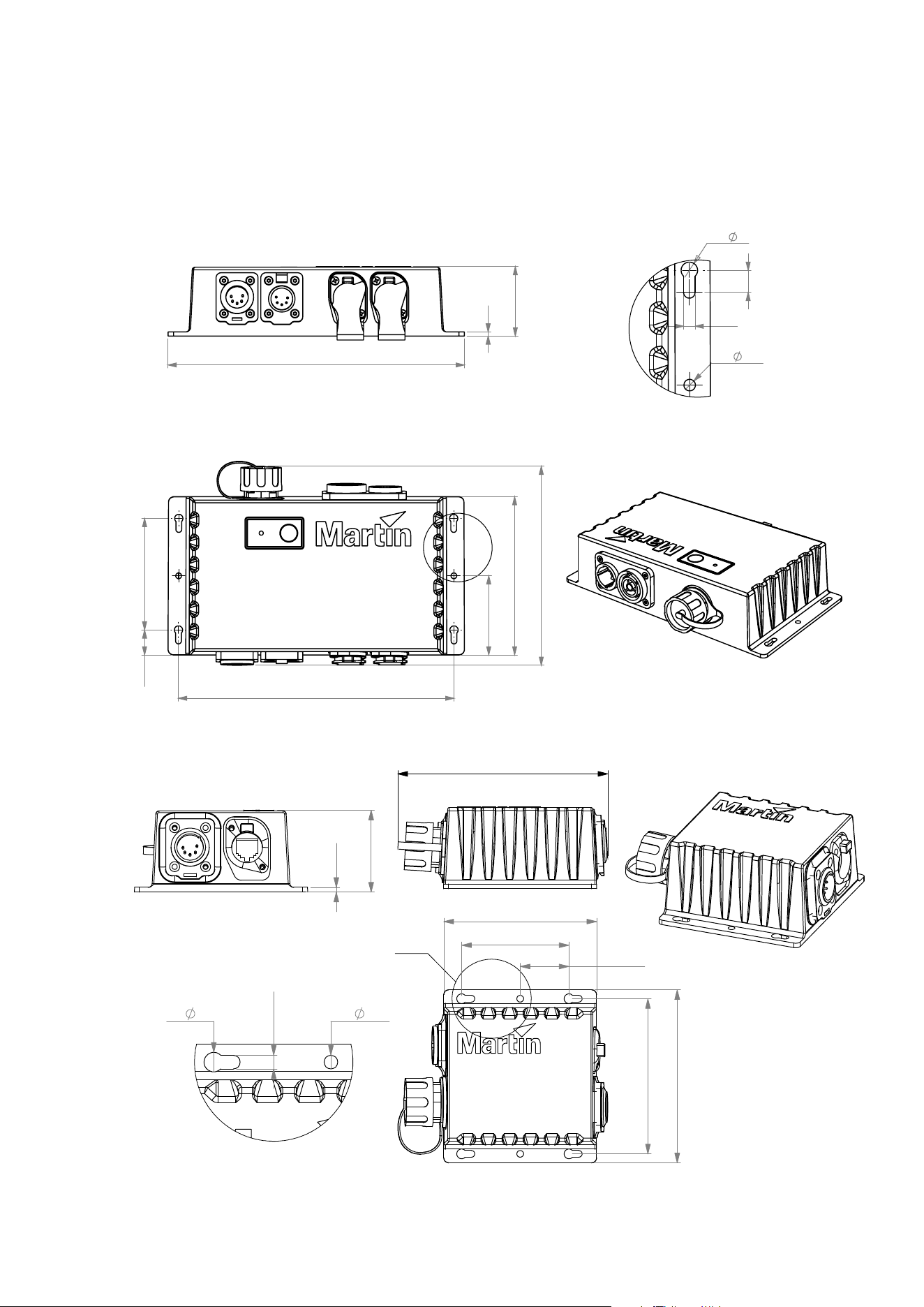
Dimensions
Active Junction Box Power-DMX-Ethernet to PDE
115
81
18.2
57.5
199.9
145
A
3
50.5
215
4x
6
8
2x
4.2
4.2
DETAIL A
SCALE 1 : 1
Passive Junction Box Power-DMX-Ethernet to PDE
3
129
94
4- 6
2- 4.2
66
30
A
Detail A
96
4.2
107
51
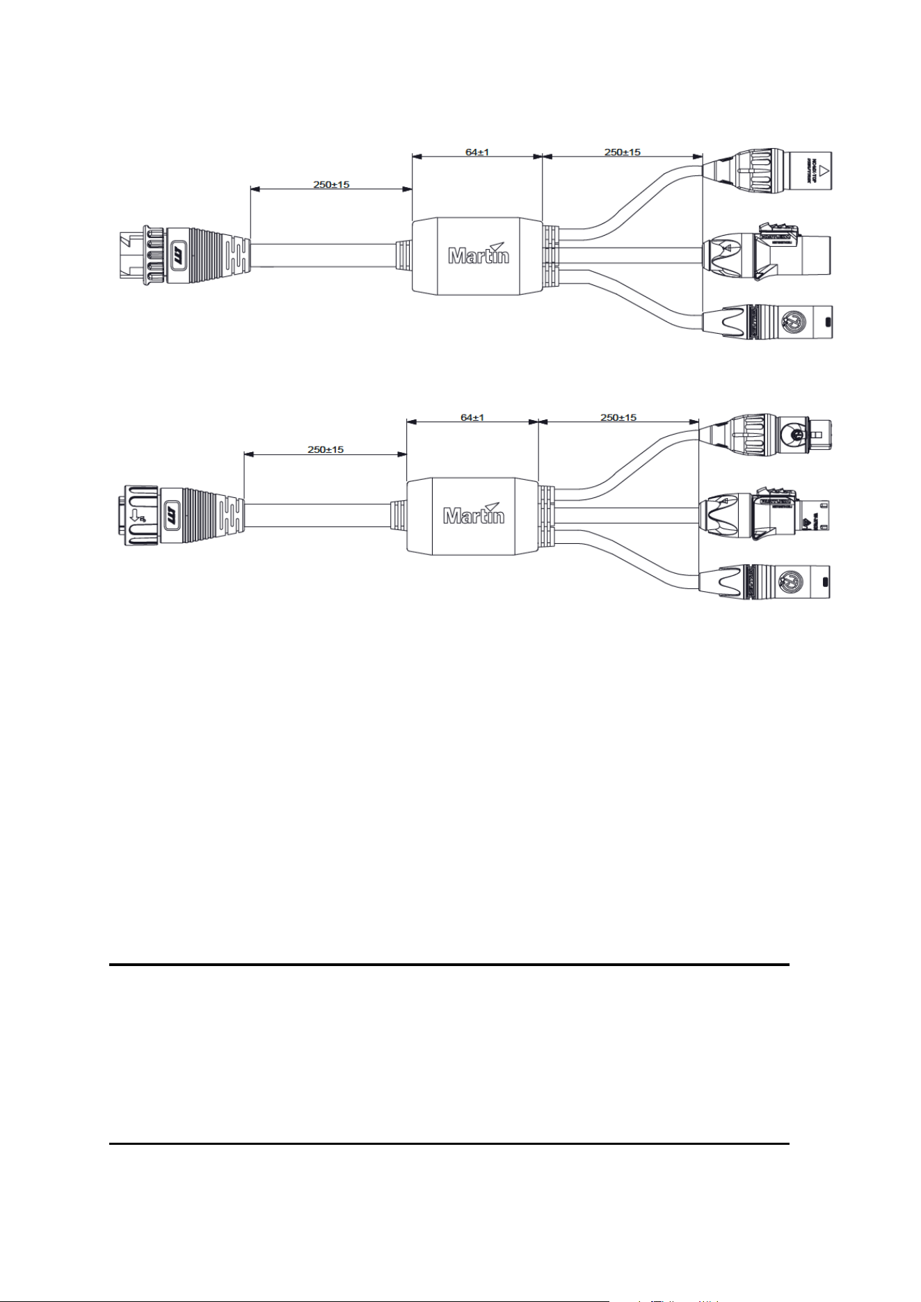
Break-In Cable Power-DMX-Ethernet to PDE
Break-Out Cable PDE to Power-DMX-Ethernet
All dimensions are given in millimeters.
© 2012-2021 HARMAN PROFESSIONAL DENMARK ApS. All rights reserved. Features, specifications and appearance
are subject to change without notice. HARMAN PROFESSIONAL DENMARK ApS and all affiliated companies disclaim
liability for any injury, damage, direct or indirect loss, consequential or economic loss or any other loss occasioned by the
use of, inability to use or reliance on the information contained in this document. Martin is a registered trademark of
HARMAN PROFESSIONAL DENMARK ApS registered in the United States and/or other countries.
HARMAN PROFESSIONAL DENMARK ApS • Olof Palmes Alle 44 • 8200 Aarhus N • Denmark
HARMAN PROFESSIONAL SOLUTIONS U.S. • 8500 Balboa Blvd. • Northridge • CA 91329 • USA
www.martin.com
PDE Active/Passive Junction Box, Break-In/Out Cable User Guide Revision B

Martin PDE Junction Box / Break-In / Break-Out Cable user guide 5
Safety information
WARNING!
Read the safety precautions in this manual before installing, operating or
servicing this product.
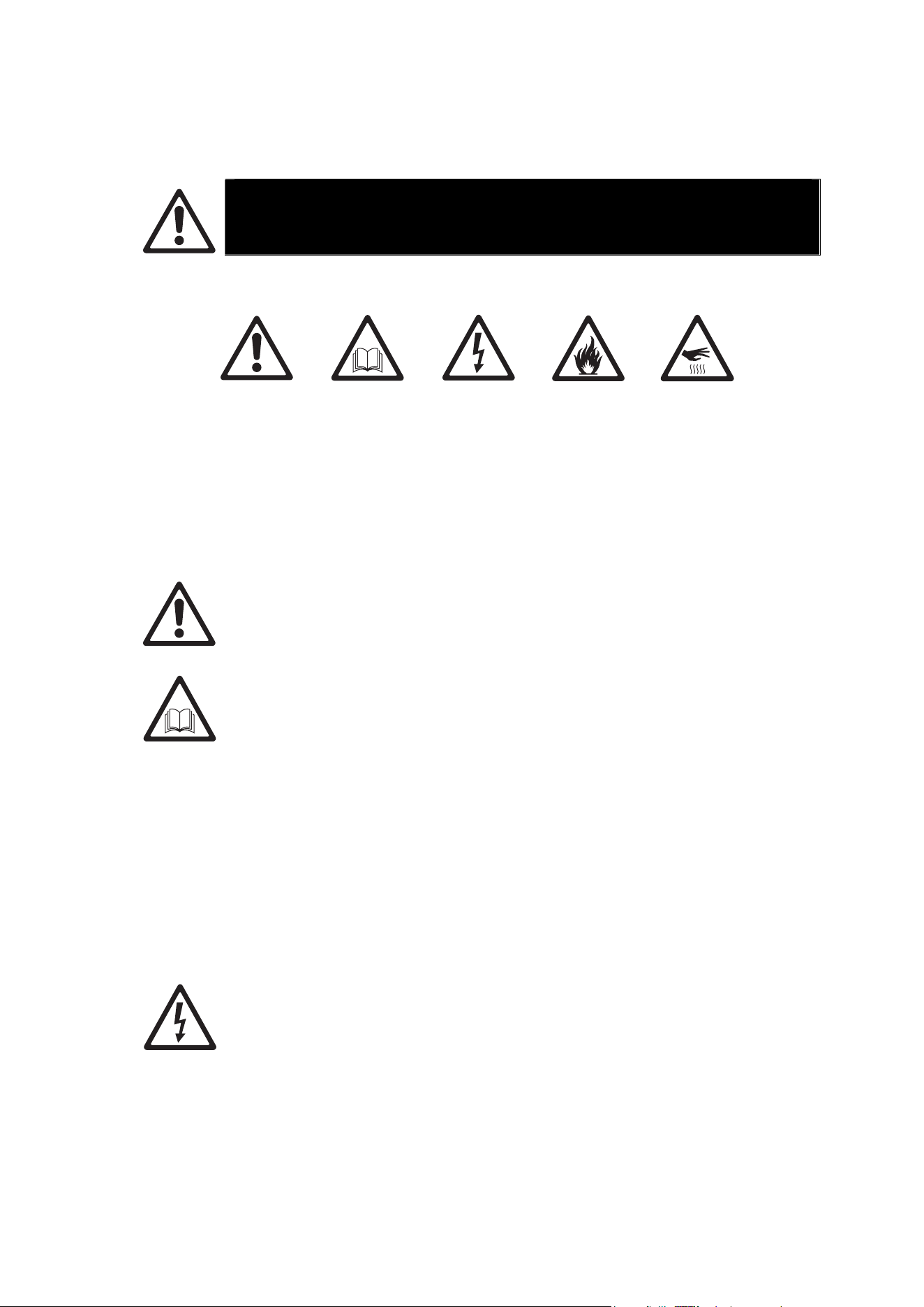
The following symbols are used to identify important safety information on the product and in this
manual:
Warning!
Safety
hazard. Risk
of severe
injury or
death.
Warning!
See user
manual for
important
safety
information.
Warning!
Hazardous
voltage. Risk
of lethal or
severe
electric
shock.
Warning!
Fire hazard.
Warning!
Hot surfaces.
This lighting product is for professional use only and must be installed by a
qualified technician. It is not for household use. It presents risks of severe injury or
death due to fire hazards, electric shock and falls.
Install, operate and service Martin® products only as directed in their user
manuals, or you may create a safety hazard or cause damage that is not covered
by product warranties. Follow the safety precautions listed below and observe all
warnings in this manual and printed on the product. Keep this user manual for
future use.
For the latest user documentation and other information about this and all Martin®
products, please visit the Martin® website at http://www.martin.com
If you have a
ny questions about how to install, operate or service the product
safely, please contact your Martin® distributor (see www.martin.com/distributors for
details) or in the USA on 1-844-776-4899.
Respect all locally applicable laws, codes and regulations when installing,
operating or servicing the product.
Protection from electric shock
Ensure that the product is electrically connected to ground (earth).
Disconnect the product from AC power when not in use.
Do not open the product or remove any cover. Refer any service operation not
described in this manual to an authorized Martin Service partner.
Shut down power to the entire installation at the main power distribution board and
lock out power before carrying out any installation or maintenance work.
Use only a source of AC power that complies with local building and electrical
codes and has both overload and ground-fault (earth-fault) protection.
Isolate the product from power immediately if any seal, cover, cable, or other
component is damaged, defective, deformed or showing signs of overheating. Do
6 Martin PDE Junction Box / Break-In / Break-Out Cable user guide
not reapply power until repairs have been completed
Before using the product, check that all power distribution equipment and cables
are in perfect condition and are of suitable type for the location (including water,
pollution, temperature and UV resistance).
Do not immerse the product in water or any other fluid, or install it in a location
where flooding may occur.
When connecting multiple products in a daisy chain, observe the safety limits in
section “Safety limits for connecting devices” on page 16.
Protection from burns and fire
Do not operate the product if the ambient temperature (Ta) exceeds 40° C (104°
F).
The surface of the product can reach up to 55° C (131° F) if the product is operated
at the maximum permitted ambient temperature. Allow the product to cool for at
least 5 minutes before handling.
Install the product on a non-combustible surface (brick, concrete, plaster etc.) only.
Allow at least 0.1 m (4 in.) free space around the product.
Do not attempt to bypass thermostatic switches or fuses.
Do not modify the product in any way not described in this manual or install other
than genuine Martin® parts.
Protection from injury
Fasten the product securely to a fixed surface or structure when in use. The
product is not portable when installed.
Ensure that all supporting structures, surfaces, fasteners and lifting equipment can
bear the weight of all the devices they are intended to support plus an adequate
safety margin, and that they conform to local building and safety regulations.
Block access below the work area and work from a stable platform whenever
installing, setting, adjusting, or cleaning the product.
Do not operate the product with missing or damaged covers or shields.
If an operating problem occurs, stop using the product immediately and disconnect
it from power. Do not attempt to use a product that is obviously damaged.
Martin PDE Junction Box / Break-In / Break-Out Cable user guide 7
Précautions d'emploi
ATTENTION !
Lisez les précautions d'emploi listées dans ce manuel avant
d'installer,d'utiliser ou de faire la maintenance de l'appareil.
Les symboles ci-dessous sont utilisés pour identifier les informations de sécurité importantesl:
Attention !
Risque
important.
Risque de
blessure
sévère voire
mortelle.
Attention !
Reportez-
vous au
manuel
d'utilisation
pour les
informations
de sécurité.
Attention !
Tensions
dangereuses.
Risque de
blessure
sévère voire
mortelle par
électrisation.
Attention !
Risque
d'incendie.
Attention !
Surfaces
chaudes.
Ce produit d'éclairage est réservé à un usage professionnel et doit être installé par
un technicien qualifié uniquement. Il n'est pas destiné à un usage domestique. Il
présente des risques de blessures sévères voire mortelles par brûlure ou incendie,
électrisation et chute..
Veuillez uniquement installer, utiliser ou réaliser la maintenance des produits
Martin® en respectant les directives de leur manuel d'utilisation au risque de créer
un risque pour la sécurité ou de causer des dommages qui ne seraient pas
couverts par la garantie du produit. Suivez les précautions d'emploi listées ci-
dessous et respectez toutes les mises en garde continues dans ce manuel et
imprimées sur le produit. Gardez ce mode d'emploi pour un usage ultérieur.
Pour obtenir les dernières mises à jour de ce document ou de toute information sur
ce produit et le reste de la gamme Martin®, consultez le site web de Martin® :
http://www.martin.com
Pour toute question sur l'installation, l'utilisation ou l'entretien de cet appareil en
toute sécurité, contactez votre distributeur Martin® (voir
www.martin.com/distributors pour plus de détail) ou bien, pour les USA, appelez le
1-844-776-4899.
Respectez toutes les règlementations, codes et lois locales applicables lors de
l'installation, de l'utilisation et de la maintenance de cet appareil.
Protection contre les risques électriques
Assurez-vous que l'appareil est correctement relié à la terre électrique.
Déconnectez l'appareil du secteur lorsqu'il n'est pas en service.
N'ouvrez pas l'appareil et ne déposez aucun capot. Référez toute opération non
décrite ici à un service technique agréé par Martin.
Coupez l'alimentation de l'installation au tableau de distribution et consignez-la
avant de commencer l'installation ou la maintenance.
N'utilisez qu'une source d'alimentation AC compatible avec les codes locaux de la
8 Martin PDE Junction Box / Break-In / Break-Out Cable user guide
construction et de l'électricité et protégée contre les surintensités et les défauts
différentiels.
Isolez immédiatement l'appareil du secteur si un joint, un capot, un câble ou tout
autre composant est endommagé, défectueux, déformé ou montre des signes de
surchauffe. Ne remettez pas le système sous tension tant que les réparations n'ont
pas été effectuées.
Avant d'utiliser l'appareil, vérifiez que tous les équipements de distribution
d'énergie et que tous les câbles sont en parfaite condition et sont adaptés au lieu
d'installation (incluant humidité, pollution, température et résistance aux UV).
N'immergez pas l'appareil dans l'eau ou dans tout autre fluide. Ne l'installez pas
dans une zone inondable.
Lors du raccordement de produits en cascade, respectez les limites de sécurité
données dans la section "Limites de sécurité pour la connexion des appareils" en
page 16.
Protection contre les incendies et les brûlures
N'utilisez pas l'appareil si la température ambiante (Ta) dépasse 40° C (104° F).
La surface de l'appareil peut atteindre 55° C (131° F) si l'appareil est utilisé à la
température ambiante maximale permise. Laissez l'appareil refroidir au moins
pendant 5 minutes avant de le manipuler.
Installez l'appareil sur une surface non combustible (brique, béton plâtre etc.)
uniquement.
Laissez au moins 0,1 m (4 in.) d'espace libre autour de l'appareil.
N'essayez pas de contourner l'action des organes de protection tels que fusibles
ou interrupteurs thermostatiques.
Ne modifiez pas l'appareil autrement que selon les directives contenues dans ce
manuel et n'installez que des pièces détachées d'origine Martin®.
Protection contre les blessures
Fixez l'appareil fermement à une surface fixe lors de son utilisation. L'appareil n'est
pas transportable pendant son fonctionnement.
Assurez-vous que toutes les structures et surfaces porteuses et que tous les
accessoires de fixation et de levage supportent le poids de tous les appareils qu'ils
reçoivent avec une conséquente marge de sécurité et qu'ils sont conformes aux
codes et aux règles de sécurité locales et de la construction.
Interdisez l'accès sous la zone de travail et travaillez sur une plateforme stable lors
de l'installation, des réglages, du paramétrage ou du nettoyage de l'appareil.
N'utilisez pas l'appareil s'il manque des capots ou des protections.
En cas de problème de fonctionnement, arrêtez immédiatement l'appareil et
déconnectez-le du secteur. N'essayez pas d'utiliser un appareil visiblement
endommagé.
Martin PDE Junction Box / Break-In / Break-Out Cable user guide 9
Sicherheitshinweise
WARNUNG!
Lesen Sie die Sicherheitshinweise, bevor Sie das Produkt installieren, in
Betrieb nehmen, verwenden oder reparieren.
Die folgenden Warnhinweise werden in dieser Anleitung und auf dem Produkt verwende:
Warnung!
Sicherheitsrisiko.
Verletzungs-
oder
Lebensgefahr
Warnung!
Wichtiger
Sicherheits-
hinweis. Bedie-
nungsanleitung
beachten.
Warnung!
Hochspannung.
Verletzungs-
oder
Lebensgefahr.
Warnung!
Feuergefahr.
Warnung!
Heiße Oberfläche.
Verbrennungsgefahr.
Nicht berühren.
Dieses Produkt ist nur für den professionellen Einsatz zugelassen. Er muss von
einem qualifizierten Techniker installiert werden. Die Verwendung in privaten
Haushalten ist unzulässig. Von diesem Produkt gehen erhebliche
Verletzungsgefahren und Lebensgefahr durch Feuer und Verbrennung,
elektrischen Schlag und Absturz aus.
Installieren, verwenden und warten Sie Produkte und Zubehör von Martin® nur,
wie in der jeweiligen Anleitung vorgeschrieben. Andernfalls erzeugen Sie ein
Sicherheitsrisiko oder verursachen Schäden, die von der Gewährleistung
ausgeschlossen sind. Befolgen Sie die Sicherheitshinweise und beachten Sie alle
in dieser Anleitung, in der Bedienungsanleitung oder auf dem Produkt
gegebenenWarnungen. Bewahren Sie diese Anleitung auf.
Die neueste Anleitung und andere Dokumente für alle Produkte von Martin® finden
Sie zum Download auf der Webseite www.martin.com.
Wenn Sie Fragen zur sicheren Installation und zum sicheren Betrieb dieses
Produkts haben, wenden Sie sich bitte an den technischen Support von Harman
Professional:
• Nordamerika: HProTechSupportUSA@harman.com, Telefon: (844) 776-4899
• Rest der Welt: Bitte wenden Sie sich an Ihren nationalen Vertrieb.
Beachten Sie alle allgemeinen und lokalen Gesetze, Normen und Vorschriften,
wenn Sie das Gerät installieren, in Betrieb nehmen, verwenden oder reparieren.
Schutz vor elektrischem Schlag
Erden Sie das Gerät immer elektrisch.
Trennen Sie das Gerät allpolig von der Stromquelle, wenn es nicht in Gebrauch ist.
Öffnen Sie das Gerät nicht. Entfernen Sie keine Abdeckungen. Überlassen Sie alle
Wartungsarbeiten, die nicht in dieser Anleitung beschrieben werden, einem
autorisierten Martin Servicepartner.
Trennen Sie die gesamte Installation vom Netz und sichern Sie gegen
Wiedereinschalten, bevor Sie Installations- oder Wartungsarbeiten ausführen.
10 Martin PDE Junction Box / Break-In / Break-Out Cable user guide
Verwenden Sie nur eine Wechselstromquelle, die den allgemeinen und lokalen
Sicherheitsvorschriften entspricht. Die Stromquelle muss mit einer
Überlastsicherung und einem Fehlerstrom-Schutzschalter (RCD) abgesichert sein.
Trennen Sie das Gerät sofort allpolig von der Stromquelle, wenn eine Dichtung,
eine Abdeckung, die Netzleitung oder der Netzstecker beschädigt, defekt oder
nass sind oder Zeichen von Überhitzung aufweisen. Verwenden Sie das Gerät
nicht, bis die Reparatur abgeschlossen ist.
Prüfen Sie vor Inbetriebnahme alle elektrischen Verteilereinrichtungen und
Leitungen auf Fehlerfreiheit, ausreichende Dimensionierung für alle
angeschlossenen Verbraucher und Eignung für die Installation (Wasser,
Verschmutzung, Temperatur, UV-Beständigkeit).
Tauchen Sie das Gerät nicht in Wasser oder eine andere Flüssigkeit ein. Der
Montageort darf nicht überflutet werden können.
Wenn Sie mehrere Geräte in Reihe mit der Stromquelle verbinden, beachten Sie
bitte Sicherheitshinweise im Abschnitt „Sicherheitshinweise zum seriellen
Anschluss der Geräte“ auf Seite 16.
Schutz vor Verbrennung und Feuer
Verwenden Sie das Gerät nicht bei Umgebungstemperaturen (Ta) über 40° C.
Das Gehäuse des Geräts wird während des Betriebs bei höchster zulässiger
Umgebungstemperatur bis zu 55° C warm. Lassen Sie das Gerät nach dem
Ausschalten mindestens 5 Minuten abkühlen, bevor Sie es berühren.
Installieren Sie das Gerät nur auf einer nicht brennbaren Oberfläche (Ziegel,
Beton, Pflastersteine usw.).
Der Freiraum um das Gerät muss mindestens 0,1 m betragen.
Überbrücken Sie niemals Überhitzungs-Schutzschalter oder Sicherungen.
Nehmen Sie am Gerät keine Veränderungen, die nicht in dieser Anleitung oder der
Anleitung beschrieben werden, vor. Verwenden Sie nur Original Martin®
Ersatzteile.
Schutz vor Verletzung
Befestigen Sie das Gerät während des Betriebs sicher an einer Oberfläche oder
tragenden Struktur. Das Gerät darf während des Betriebes nicht bewegt werden.
Prüfen Sie vor der Montage des Geräts, das die tragende Struktur und alle
Anschlagmittel mindestens für das Gewicht aller die Struktur belastenden Geräte
ausgelegt ist. Beachten Sie alle lokalen Sicherheitsvorschriften.
Sperren Sie den Bereich unterhalb des Geräts und arbeiten Sie von einer stabilen
Plattform aus, wenn Sie das Gerät installieren, Wartungsarbeiten ausführen oder
bewegen.
Verwenden Sie das Gerät nicht, wenn Abdeckungen, Abschirmungen oder
optische Komponenten fehlen oder defekt sind.
Trennen Sie das Gerät sofort allpolig von der Stromquelle, wenn während des
Betriebs Probleme auftreten. Verwenden Sie kein Gerät, das offensichtlich
beschädigt ist.

Martin PDE Junction Box / Break-In / Break-Out Cable user guide 11
Introduction
The Junction Boxes and Adapter Cables described in this document provide power and data to
Martin products using the hybrid PDE connector and cabling system. This system carries line
voltage, DMX and Ethernet data over a single hybrid cable, enabling easy cabling and daisy-
chaining of products.
The Active Junction Box contains a DMX/RDM splitter and 3-port Ethernet switch with fail-safe
bypass mechanism, and provides following connections:
x Power Input
x Power Thru (for daisy-chaining to following junction box or other product)
x DMX/RDM Input
x DMX/RDM Thru (for daisy-chaining to following junction box or other product)
x Ethernet Input
x Ethernet Thru (for daisy-chaining to following junction box or other product)
x Hybrid PDE Output towards a daisy-chain of compatible products
The Passive Junction Box is a more compact unit without any electronics inside, and provides
following connections:
x Power Input
x DMX/RDM Input
x Ethernet Input
x Hybrid PDE Output towards a daisy-chain of compatible products
The Break-In Cable offers the same functionality as the Passive Junction Box in the form of a
cable, and provides following connections:
x Power Input
x DMX/RDM Input
x Ethernet Input
x Hybrid PDE Output towards a daisy-chain of compatible products
The Break-Out Cable can be used to extract power and/or data from the end of a chain of
compatible products, and provides following connections:
x Hybrid PDE Input from a daisy-chain of compatible products
x Power Output
x DMX/RDM Output
x Ethernet Output
Before using the product for the first time
1. Read ‘Safety information’ on page 5 before installing, operating or servicing the product.
2. Unpack and ensure that there is no transportation damage before using the product. Do not
attempt to operate a damaged product.
3. Before operating, ensure that the voltage and frequency of the power supply match the power
requirements of the product.
4. Obtain a power cable fitted with Neutrik powerCON TRUE1 connector. Cables are available
from Martin (see Accessories list on page 31).
5.
Check the support pages on the Martin® website at www.martin.com for the most recent user
documentation and technical information about the product. Martin® user manual revisions
are identified by the revision letter at the bottom of the inside cover.
12 Martin PDE Junction Box / Break-In / Break-Out Cable user guide
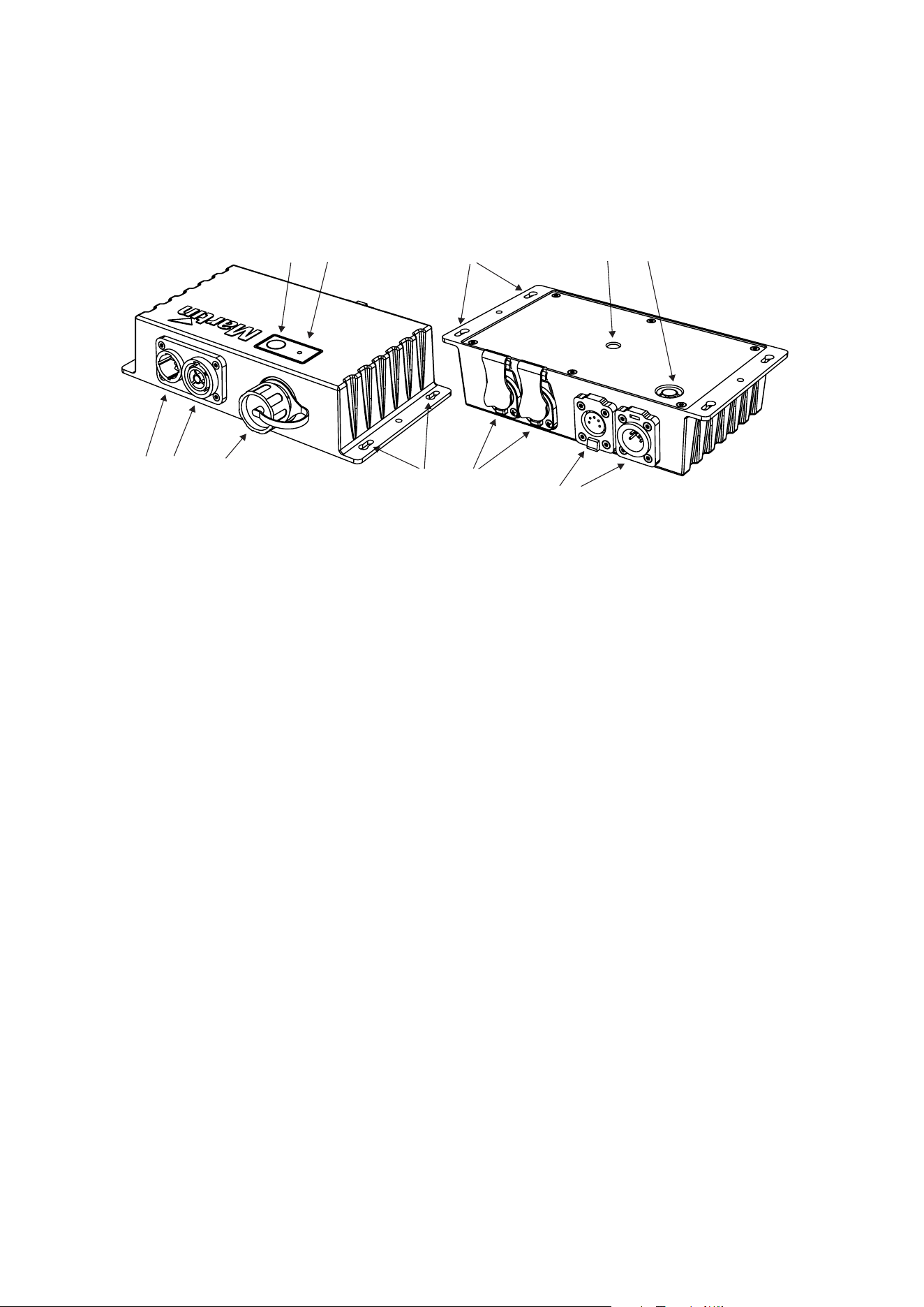
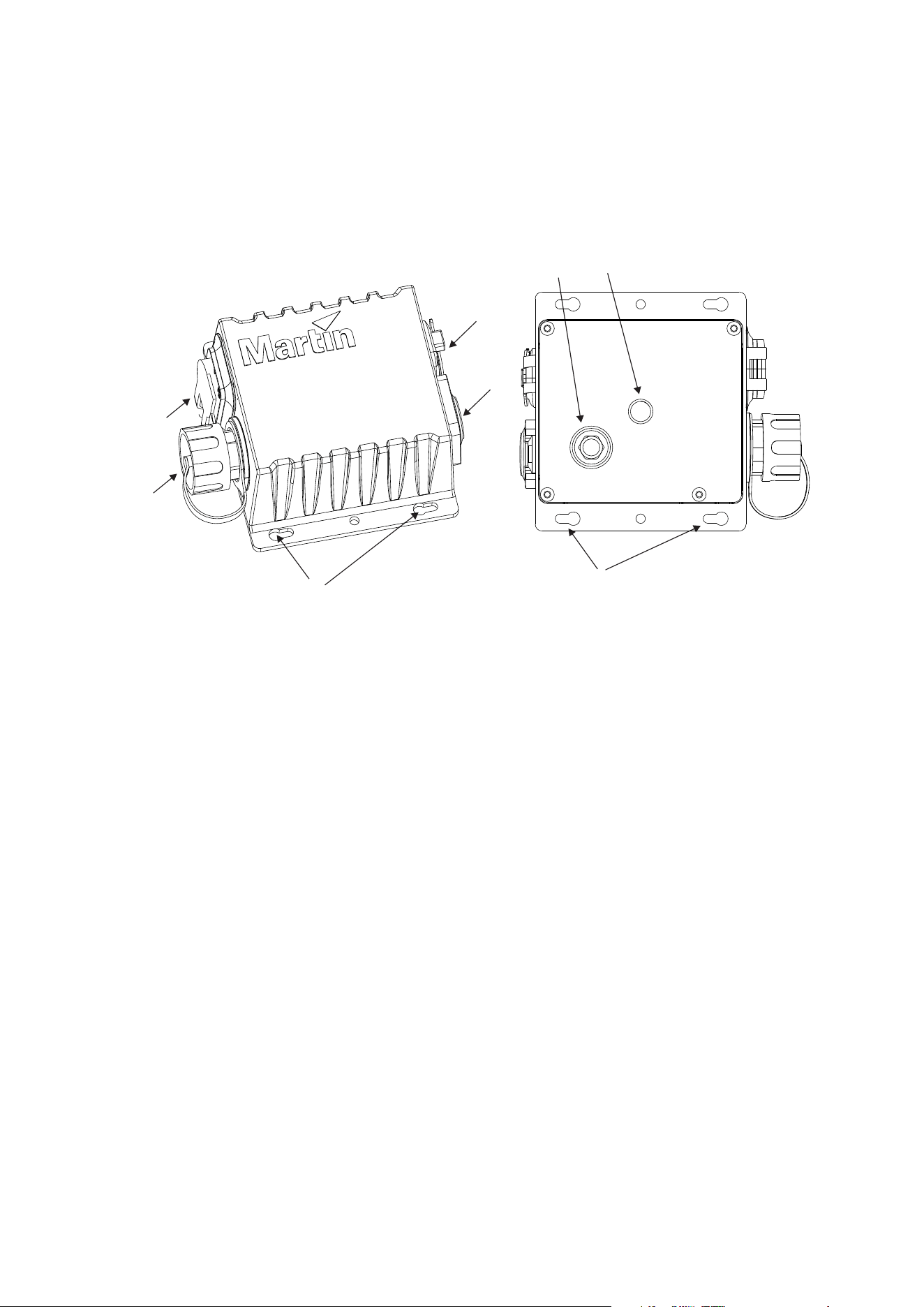
Active Junction Box overview
12
Underside view
1110
7
6
89
12
5
3
4
1 – Neutrik powerCON TRUE1 input
2 – Neutrik powerCON TRUE1 link through
3 – Hybrid PDE output connector
4 – Test / Reset button
5 – Status LED
6 – Keyhole slots for mounting to wall / surface (both sides)
7 – Neutrik etherCON input / link through
8 – Neutrik XLR-5 DMX link through
9 – Neutrik XLR-5 DMX input
10 – Safety bond attachment point (both sides)
11 – M10 hole for adding clamp (on underside of box) maximum bolt length 22mm
12 – Goretex valve for pressure regulation
Martin PDE Junction Box / Break-In / Break-Out Cable user guide 13
Passive Junction Box overview
5
3
4
1
2
Underside view
7
6
8
1 – Neutrik PowerCON TRUE1 input
2 – Hybrid PDE output connector
3 – Neutrik etherCON input
4 – Neutrik XLR5 DMX input
5 – Keyhole slots for mounting to wall / surface (both sides)
6 – Safety bond attachment point (both sides)
7 – Goretex valve for pressure regulation
8 – M10 hole for adding clamp (on underside of box) maximum bolt length 22mm
14 Martin PDE Junction Box / Break-In / Break-Out Cable user guide
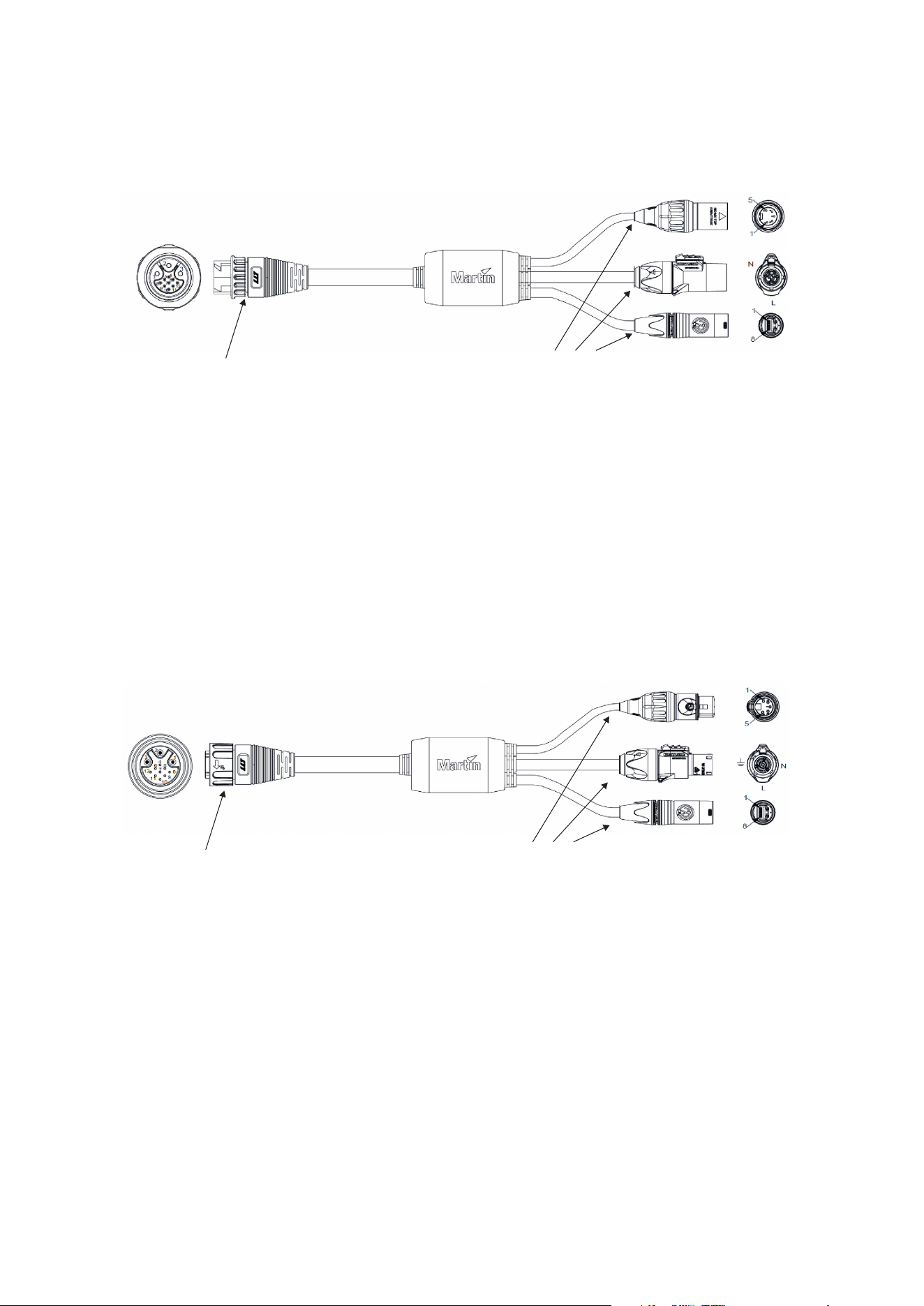
Break-In Cable overview
1
234
1 – Hybrid PDE output connector to daisy chain of compatible fixtures
2 – DMX/RDM input (Neutrik XLR5)
3 – Power input (Neutrik powerCON TRUE1)
4 – Ethernet input (Neutrik etherCON)
Break-Out Cable overview
1
234
1 – Hybrid PDE input connector from daisy chain of compatible fixtures
2 – DMX/RDM output (Neutrik XLR5)
3 – Power output (Neutrik powerCON TRUE1)
4 – Ethernet output (Neutrik etherCON)
Martin PDE Junction Box / Break-In / Break-Out Cable user guide 15
Physical installation (Junction Boxes)
Warning! Read ‘Safety information’ on page 5 before installing the product.
Wa
rning! The safety and suitability of lifting equipment, installation location,
anchoring method, mounting hardware and electrical installation are the
responsibility of the installer. All local safety regulations and legal requirements
must be observed when installing and connecting the PDE Junction Box.
Installation must be carried out by qualified professionals only.
Contact your Martin supplier for assistance if you have any questions about how to install this
product safely.
Product location
The PDE Junction Box is fully IP65 rated and may be used indoors or in a temporary outdoor
location.
Observe the following limitations in selecting a location:
x Respect the limitations listed under Safety information’ on page 5.
x Do not in
stall the fixture in a wet environment with the back side of the fixture facing
upwards, as water may collect around the Goretex pressure regulation valve.
x Make sure all unused connectors are always covered with the sealing cap provided, to
prevent water ingress.
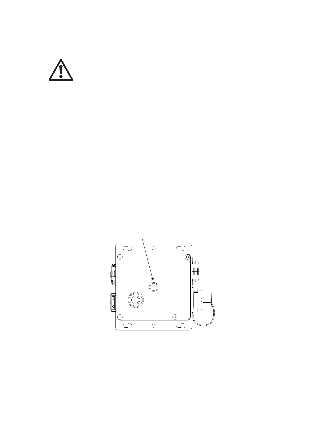
Mounting the junction box
The junction box may be mounted directly to a surface using the holes provided on the side
flanges, or a rigging clamp (such as the Super Lightweight Half Coupler Rigging Clamp black:
P/N 91602018, listed in the accessories) may be attached to the rear side using an M10 bolt,
maximum depth into box 22mm.
(this picture shows the Passive Junction Box but the Active Junction Box is similar)
x If the Junction Box is rigged to a truss or mounted where it could cause injury by falling,
a safety cable bond must be fitted to it using the 6 mm safety bond attachment points
on the side flanges. The safety cable must comply with EN/IEC 60598-2-17:2018
Section 17.7.4 or BGV C1 / DGUV 17, and must be capable of bearing a static
suspended load at least six times (or more if required by locally applicable regulations)
the weight that it secures.

16 Martin PDE Junction Box / Break-In / Break-Out Cable user guide
AC power and data connection to Active
Junction Box
Warning! Read ‘Safety information’ on page 5 before installing the product.
For p
rotection from electric shock, the power input to the Junction Box must be
grounded (earthed). The power distribution circuit must be equipped with a 16A
(EU) / 20A (US) fuse or circuit breaker and ground-fault (earth-fault) protection.
AC power and control data are connected to the Junction Box. Fixtures may then be connected in
a daisy chain to each junction box using a hybrid PDE cable which carries both power and data.
The quantity of fixtures which may be connected in a single daisy chain is described in the user
manual for each type of fixture, but is always limited to a maximum load of 16 A.
Safety limits for connecting devices
As the fixtures are connected in a chain, there is a limit to how many fixtures you can link
together and how far apart they can be.
x Maximum fixture loading of 16A connected in a chain (see individual fixture’s user
manual).
x When DMX is being used as control protocol, the total length of Hybrid PDE cable must
not exceed 300 m (measured between active junction box and last fixture on the chain).
x When Art-Net, sACN or P3 is being used as control protocol, the total length of hybrid
PDE cable between active junction box and first fixture must not exceed 90 m. The
length of hybrid PDE cable between any two daisy-chained products may also not
exceed 90 m.
x Install the sealing cap on the thru connector of the last product in the chain.
AC power connection to Junction Box
Do not use an external dimming system to supply power to the Active Junction Box, as this may
cause damage to the products that is not covered by the product warranty.
Socket outlets or external power switches used to supply the system with power must be located
near the system and easily accessible so that the system can easily be disconnected from power.
If you install a power plug on the power cable, install a grounding type (earthed) plug with integral
cable grip that is suitable for your local mains voltage at a current of 16A. Follow the plug
manufacturer’s instructions and connect the wires in the power cable as shown in this table:
Live or L Neutral or N
Earth, Ground or
US system
Black White Green
EU system
Brown Blue Yellow/green
If you need to install a Neutrik powerCON TRUE1 connector on a power cable, follow the
instructions on the Neutrik website at www.neutrik.com
.
The product has an auto-ranging power supply that accepts AC mains power at 100-240 V at
50/60 Hz. Do not apply AC mains power at any other voltage or frequency to the product.
Martin PDE Junction Box / Break-In / Break-Out Cable user guide 17
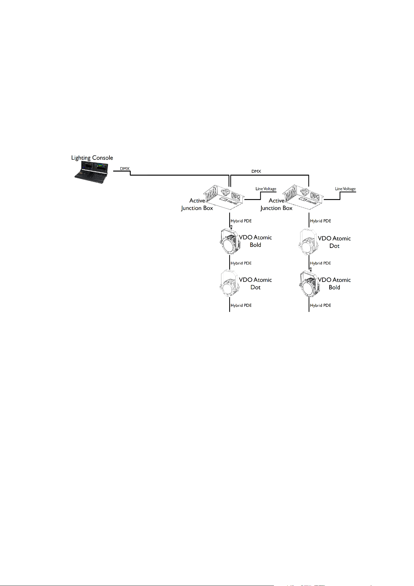
Data connection to Active Junction Box using DMX512
In a DMX-controlled system, an RDM-compliant DMX lighting controller sends a DMX control
data signal over a DMX link to the Junction Boxes of the system, and then over the hybrid link to
the fixtures.
The Active Junction box contains an active DMX/RDM splitter, so the Hybrid PDE output is
completely isolated from the DMX In & Thru ports. This means that the Active Junction box
counts as a single DMX/RDM device on the DMX line coming from the lighting console,
regardless the amount of fixtures connected to its PDE output.
The DMX In & Thru ports are hardwired to each other. So even if the Active Junction Box loses
power, it will relay data between the two XLR connectors.
The DMX link requires DMX cable. It can be a maximum 300 m (1000 ft.) in length (measured
between lighting console, DMX node or DMX splitter and last Active Junction Box on the chain)
and must run in one single daisy-chain, but it can be extended or split into branches using an
RDM-compliant amplifier/splitter. Alternatively, you can run the DMX signal from the controller
over Ethernet cable using Art-Net protocol and convert it to a DMX-compliant signal with an Art-
Net to DMX converter.
For reliable DMX and RDM data transfer, it is recommended to terminate each branch with a
termination plug – this contains a 120 ohm resistor between the cold and hot DMX data lines
(pins 2 and 3 on XLR5, pins 4 and 7 on PDE connector). This means that both an unused DMX
thru port on the Active Junction Box as well as the female PDE connector of the last fixture on a
chain need to be fitted with such a termination plug.
The total length of Hybrid PDE cables combined must not exceed 300 m (measured between
Active Junction Box and last fixture on the chain).
If you would like assistance with creating a DMX link, your Martin® supplier will be glad to advise.
The number of fixtures that you can control on one DMX link is limited by the number of DMX
channels each fixture will use and the 512 DMX channels available in one DMX universe at the
DMX controller. Each time you have used 512 channels, you must create a new DMX link that is
connected to a new DMX universe on the controller. Note that this limit applies to the DMX link.
The maximum safety limits that apply to the chain of fixtures and cable (see “Safety limits for
connecting devices” on page 16) take priority and must be respected in all cases.
D
MX512 data is connected to the junction box using the XLR5 connector. The pin-out is:
x pin 1 = shield
x pin 2 = cold (-)
x pin 3 = hot (+)
(this example shows the VDO
Atomic Bold and VDO Atomic
Dot fixtures, but any mix of
Martin products with PDE
interface can be used)
18 Martin PDE Junction Box / Break-In / Break-Out Cable user guide
Pins 4 and 5 in the XLR connectors are not used.
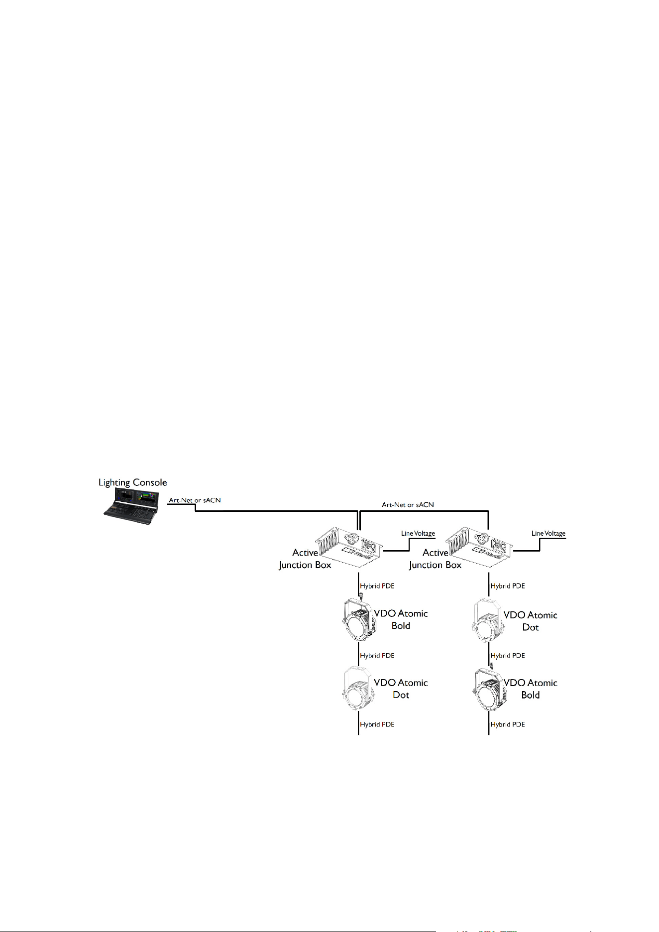
Data connection to Active Junction Box using Art-Net or sACN
Art-Net or sACN data is connected to the system using either of the two etherCON sockets on
the Active Junction Box. The other etherCON socket can then be used to daisy-chain the signal
to another Active Junction Box or other equipment compatible with Art-Net or sACN.
x The two etherCON ports on the Active Junction Box can operate at 100Mbit/s or 1Gbit/s
link speed, so they will adjust to the highest speed supported by the console or network
switch.
x The Active Junction Box features a fail-safe bypass mechanism between the two
etherCON ports. So even if the Active Junction Box loses power, it will relay data
between the two etherCON ports.
x The length of Ethernet cable between the console (or network switch) and the Active
Junction Box must not exceed 90 m.
x The length of Ethernet cable between an Active Junction Box and the next daisy-
chained Active Junction Box must not exceed 90 m.
x A shielded Ethernet cable must be used between the console (or network switch) and
the Active Junction Box. Use shielded twisted-pair Ethernet cable of type S/UTP,
SF/UTP, S/STP or SF/STP only. The cable must be rated Cat 5e or better. The cable
shield must be electrically connected to connector housings, and the other devices on
the data link must also support shielded connections.
x The Hybrid PDE output port on the Active Junction Box will always operate at 100Mbit/s
link speed towards the fixtures.
x The total length of Hybrid PDE cables between the Active Junction Box and the first
fixture must not exceed 90 m.
x The length of hybrid PDE cable between any two daisy-chained fixtures may also not
exceed 90 m.
x Caution: To avoid ground loops and damage of equipment, make sure the Ethernet is
galvanically isolated when linked between equipment of different potentials or power
sources.
(this example shows the VDO
Atomic Bold and VDO Atomic
Dot fixtures, but any mix of
Martin products with PDE
interface can be used)
Martin PDE Junction Box / Break-In / Break-Out Cable user guide 19
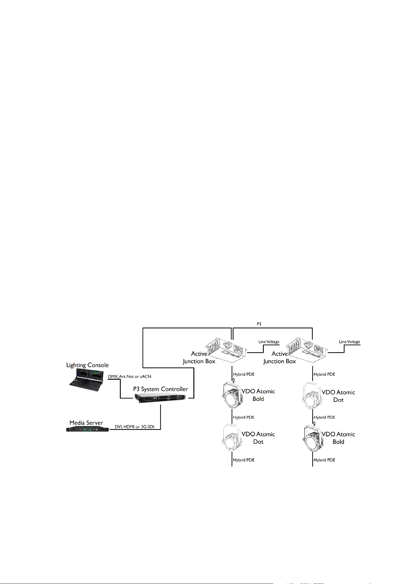
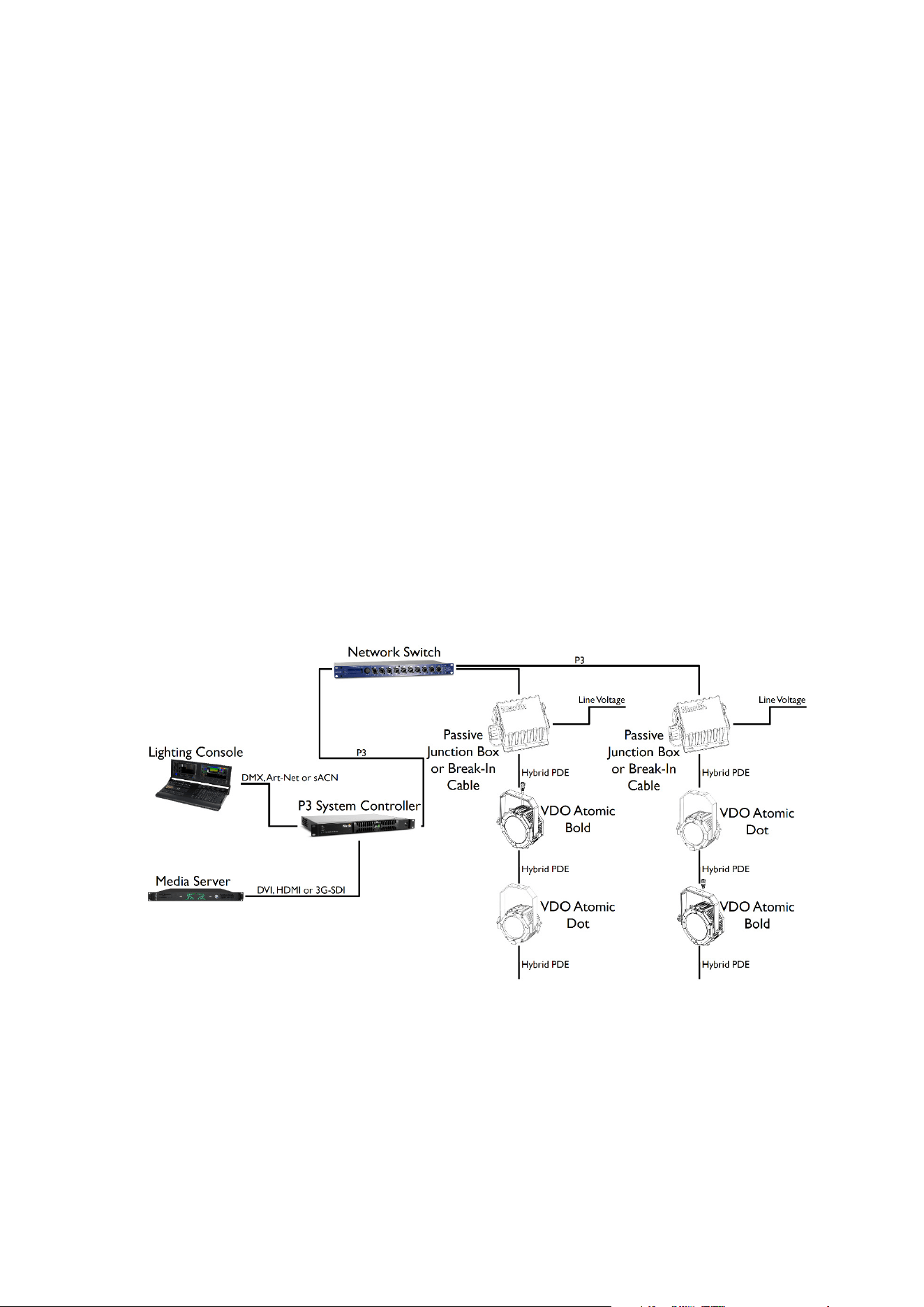
Data connection to Active Junction Box using P3
The Martin P3 System Controller combines control information from the lighting console with a
video feed from a media server. This is then distributed to the fixtures using the P3 protocol. The
P3 signal is connected to the system using any of the two etherCON sockets on the Active
Junction Box. The other etherCON socket can then be used to daisy-chain the signal to another
Active Junction Box or other equipment compatible with P3.
x The two etherCON ports on the Active Junction Box can operate at 100Mbit/s or 1Gbit/s
link speed, so they will adjust to the highest speed supported by the P3 System
Controller or network switch.
x The Active Junction Box features a fail-safe bypass mechanism between the two
etherCON ports. So even if the Active Junction Box loses power, it will relay data
between the two etherCON ports.
x The length of Ethernet cable between the P3 System Controller (or network switch) and
the Active Junction Box must not exceed 90 m.
x The length of Ethernet cable between an Active Junction Box and the next daisy-
chained Active Junction Box must not exceed 90 m.
x A shielded Ethernet cable must be used between the P3 System Controller (or network
switch) and the Active Junction Box. Use shielded twisted-pair Ethernet cable of type
S/UTP, SF/UTP, S/STP or SF/STP only. The cable must be rated Cat 5e or better. The
cable shield must be electrically connected to connector housings, and the other
devices on the data link must also support shielded connections.
x The Hybrid PDE output port on the Active Junction Box will always operate at 100Mbit/s
link speed towards the fixtures.
x The total length of Hybrid PDE cables between the Active Junction Box and the first
fixture must not exceed 90 m.
x The length of hybrid PDE cable between any two daisy-chained fixtures may also not
exceed 90 m.
(the example above shows the VDO Atomic Bold and VDO Atomic Dot fixtures, but any mix of
Martin products with PDE interface can be used)
x Caution: To avoid ground loops and damage of equipment, make sure the Ethernet is
galvanically isolated when linked between equipment of different potentials or power
sources.

20 Martin PDE Junction Box / Break-In / Break-Out Cable user guide
AC power and data connection to Passive
Junction Box or Break-In Cable
Warning! Read ‘Safety information’ on page 5 before installing the product.
For p
rotection from electric shock, the power input to the Junction Box or Break-In
cable must be grounded (earthed). The power distribution circuit must be equipped
with a 16A (EU) / 20A (US) fuse or circuit breaker and ground-fault (earth-fault)
protection.
AC power and control data are connected to the Junction Box or Break-In Cable. Fixtures may
then be connected in a daisy chain to each junction box or break-in cable using a hybrid PDE
cable which carries both power and data. The quantity of fixtures which may be connected in a
single daisy chain is described in the user manual for each type of fixture, but is always limited to
a maximum load of 16 A.
Safety limits for connecting devices
As the fixtures are connected in a chain, there is a limit to how many fixtures you can link
together and how far apart they can be.
x Maximum fixture loading of 16A connected in a chain (see individual fixture’s user
manual).
x When DMX is being used as control protocol, the total length of DMX cable and Hybrid
PDE cable combined must not exceed 300 m (measured between lighting console,
DMX node or DMX splitter and last fixture on the chain).
x When Art-Net, sACN or P3 is being used as control protocol, the combined length of
Ethernet cable (between network switch and junction box) and hybrid PDE cable to first
fixture must not exceed 90 m. The length of hybrid PDE cable between any two daisy-
chained fixtures may also not exceed 90 m.
x Install the sealing cap on the thru connector of the last fixture in the chain.
AC power connection to Junction Box or Break-In Cable
Do not use an external dimming system to supply power to the Junction Box or Break-In cable,
as this may cause damage to the fixtures that is not covered by the product warranty.
Socket outlets or external power switches used to supply the system with power must be located
near the system and easily accessible so that the system can easily be disconnected from power.
If you install a power plug on the power cable, install a grounding type (earthed) plug with integral
cable grip that is suitable for your local mains voltage at a current of 16A. Follow the plug
manufacturer’s instructions and connect the wires in the power cable as shown in this table:
Live or L Neutral or N
Earth, Ground or
US system
Black White Green
EU system
Brown Blue Yellow/green
If you need to install a Neutrik powerCON TRUE1 connector on a power cable, follow the
instructions on the Neutrik website at www.neutrik.com
.
The fixtures have an auto-ranging power supply that accepts AC mains power at 100-240 V at
50/60 Hz. Do not apply AC mains power at any other voltage or frequency to the product.
Martin PDE Junction Box / Break-In / Break-Out Cable user guide 21
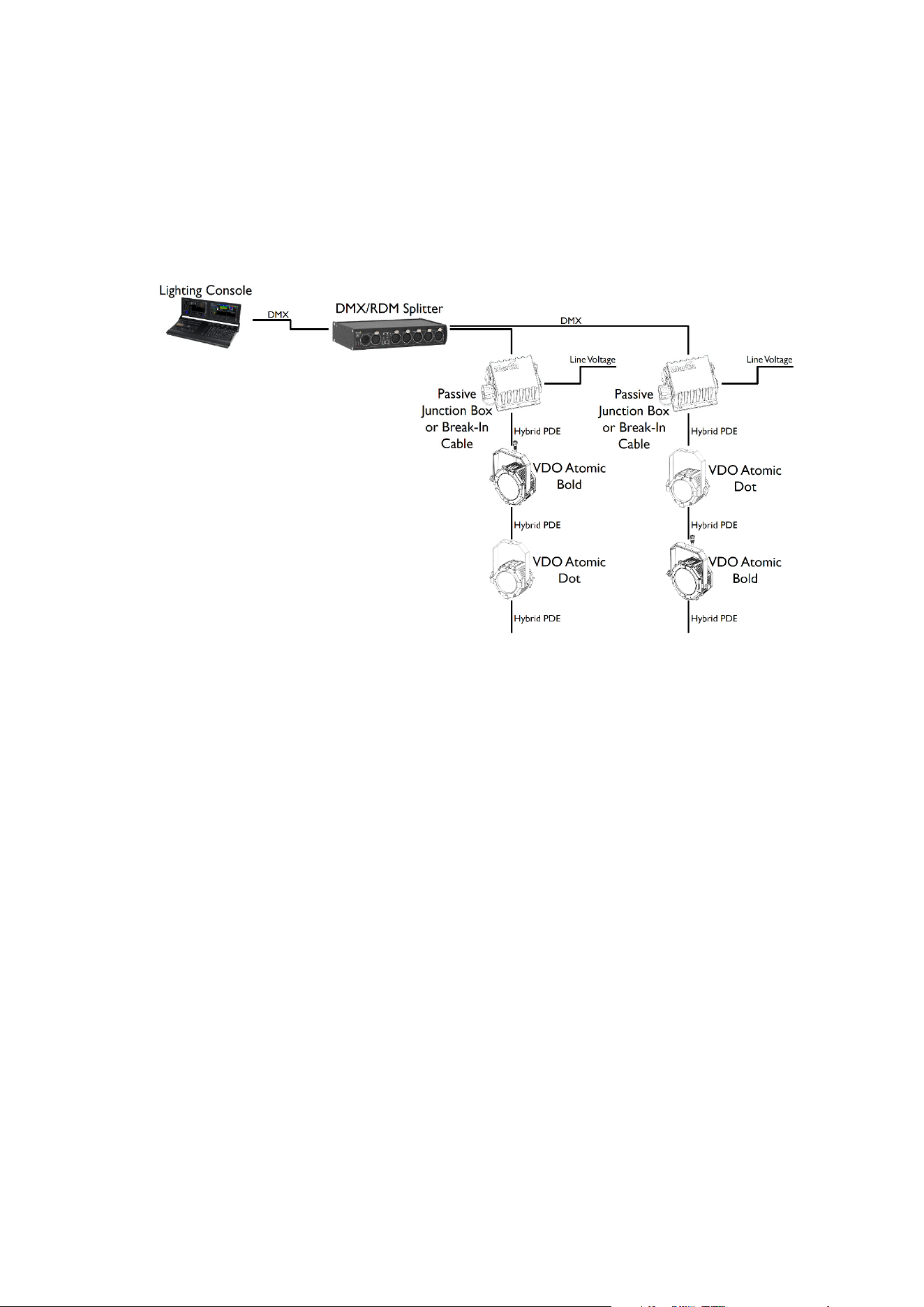
Data connection to Passive Junction Box or Break-In Cable using DMX512
In a DMX-controlled system, an RDM-compliant DMX lighting controller sends a DMX control
data signal over a DMX link to the junction boxes or break-in cables, and then over the hybrid link
to the fixtures.
A DMX pass – through connector is not provided. If you need to connect multiple Junction Boxes
or Break-In cables to the same DMX line, you must use an RDM-compliant splitter as described
below.
The DMX link requires DMX cable. It can be maximum 300 m (1000 ft.) in length and must run in
one single daisy-chain, but it can be extended or split into branches using an RDM-compliant
amplifier/splitter. Alternatively, you can run the DMX signal from the controller over Ethernet
cable using Art-Net protocol and convert it to a DMX-compliant signal with an Art-Net to DMX
converter.
For reliable DMX and RDM data transfer, it is recommended to terminate each branch with a
termination plug – this contains a 120 ohm resistor between the cold and hot DMX data lines
(pins 2 and 3 on XLR5, pins 4 and 7 on PDE connector). This means that the female PDE
connector of the last fixture on a chain need to be fitted with such a termination plug.
The total length of DMX cable and Hybrid PDE cable combined must not exceed 300 m
(measured between lighting console, DMX node or DMX splitter and last fixture on the chain).
If you would like assistance with creating a DMX link, your Martin® supplier will be glad to advise.
The number of fixtures that you can control on one DMX link is limited by the number of DMX
channels each fixture will use and the 512 DMX channels available in one DMX universe at the
DMX controller. Each time you have used 512 channels, you must create a new DMX link that is
connected to a new DMX universe on the controller. Note that this limit applies to the DMX link.
The maximum safety limits that apply to the chain of fixtures and cable (see “Safety limits for
connecting devices” on page 16) take priority and must be respected in all cases.
D
MX512 data is connected to the junction box using the XLR5 connector. The pin-out is:
x pin 1 = shield
x pin 2 = cold (-)
x pin 3 = hot (+).
Pins 4 and 5 in the XLR connectors are not used.
(this example shows the
Passive Junction Box, but the
functionality and connectivity of
the Break-In Cable is identical.
Also VDO Atomic Bold and VDO
Atomic Dot fixtures are shown,
but any mix of Martin products
with PDE interface can be used)
22 Martin PDE Junction Box / Break-In / Break-Out Cable user guide
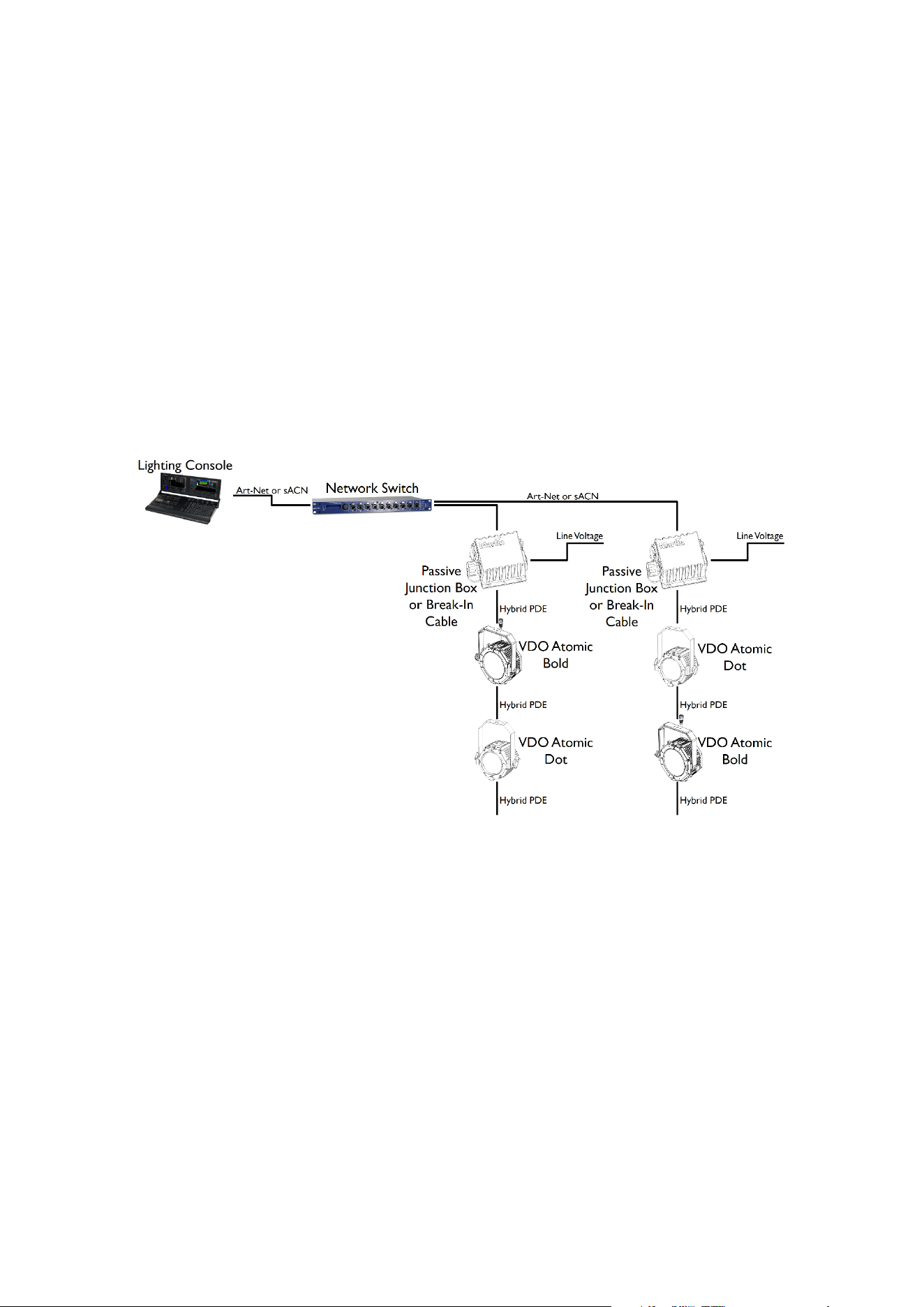
Data connection to Passive Junction Box or Break-In Cable using Art-Net
or sACN
Art-Net or sACN data is connected to the system using the etherCON socket on the Passive
Junction Box or Break-In Cable. Each Junction Box / Break-In Cable must have its own Ethernet
connection from a network switch.
x Please ensure that network switch can operate at 100Mbit Ethernet link speed towards
the junction boxes, as the PDE hybrid fixtures can only operate at that link speed.
x The combined length of Ethernet cable (between network switch and passive junction
box / break-in cable) and hybrid PDE cable to first fixture must not exceed 90 m.
x The length of hybrid PDE cable between any two daisy-chained fixtures may also not
exceed 90 m.
x A shielded Ethernet cable must be used between the between the Network Switch and
the Passive Junction Box / Break-In Cable. Use shielded twisted-pair Ethernet cable of
type S/UTP, SF/UTP, S/STP or SF/STP only. The cable must be rated Cat 5e or better.
The cable shield must be electrically connected to connector housings, and the other
devices on the data link must also support shielded connections.
x Caution: To avoid ground loops and damage of equipment, make sure the Ethernet is
galvanically isolated when linked between equipment of different potentials or power
sources.
(this example shows the
Passive Junction Box, but the
functionality and connectivity of
the Break-In Cable is identical.
Also VDO Atomic Bold and VDO
Atomic Dot fixtures are shown,
but any mix of Martin products
with PDE interface can be used)
Martin PDE Junction Box / Break-In / Break-Out Cable user guide 23
Data connection to Passive Junction Box or Break-In Cable using P3
The Martin P3 System Controller combines control information from the lighting console with a
video feed from a media server. This is distributed to the fixtures using the P3 protocol. Each
Junction Box or Break-In Cable must have its own Ethernet connection from the network switch.
x Please ensure that network switch can operate at 100Mbit Ethernet link speed towards
the Passive Junction Box / Break-In Cable, as the PDE Hybrid fixtures can only operate
at that link speed.
x Please ensure that network switch can operate at 1Gbit Ethernet link speed towards the
P3 System Controller, as it can only operate at that link speed.
x The combined length of Ethernet cable (between network switch and junction box) and
hybrid PDE cable to first fixture must not exceed 90 m.
x The length of hybrid PDE cable between any two daisy-chained fixture may also not
exceed 90 m.
x A shielded Ethernet cable must be used between the between the Network Switch and
the Passive Junction Box / Break-In Cable. Use shielded twisted-pair Ethernet cable of
type S/UTP, SF/UTP, S/STP or SF/STP only. The cable must be rated Cat 5e or better.
The cable shield must be electrically connected to connector housings, and the other
devices on the data link must also support shielded connections.
x Other P3-compatible products such as the MAC Aura PXL and P3 PowerPort 1500 can
be connected to the same network switch to operate all together from the same P3
System Controller.
(The example above shows the Passive Junction Box, but the functionality and connectivity of the
Break-In Cable is identical. Also VDO Atomic Bold and VDO Atomic Dot fixtures are shown, but
any mix of Martin products with PDE interface can be used)
x Caution: To avoid ground loops and damage of equipment, make sure the Ethernet is
galvanically isolated when linked between equipment of different potentials or power
sources.
24 Martin PDE Junction Box / Break-In / Break-Out Cable user guide
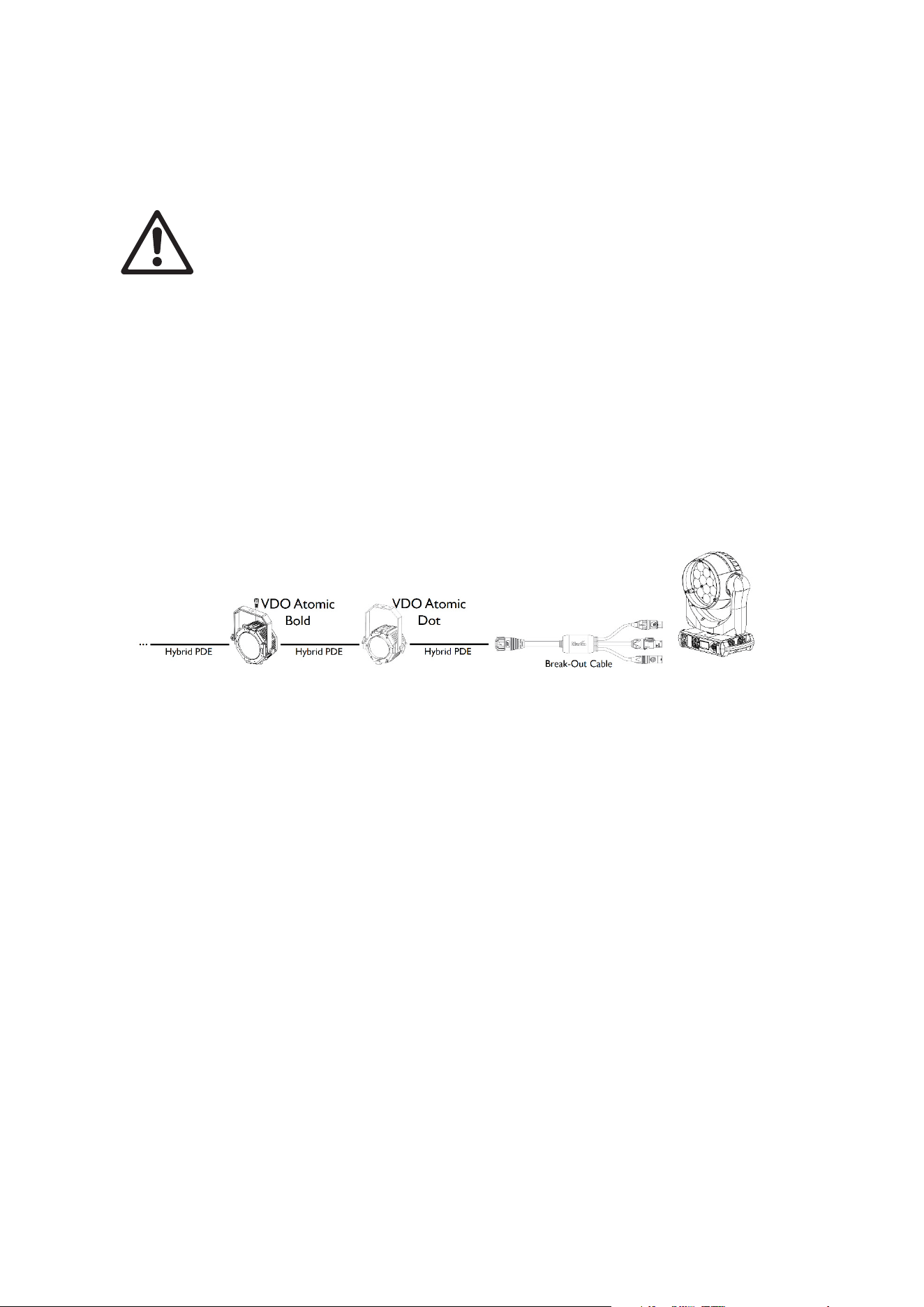
AC power and data connection using Break-
Out Cable
Warning! Read ‘Safety information’ on page 5 before installing the product.
AC po
wer and control data can be extracted from the end of a daisy-chain of Hybrid PDE
products using the Break-Out Cable.
Safety limits for connecting devices
Whe
n extracting power using the Break-Out Cable, care must be taken to not exceed a load of
16 A for the entire chain. Always calculate the load consumed by the Hybrid PDE products on the
chain to determine how much additional load can be connected using the Break-Out Cable,
without exceeding 16 A total load.
AC Power and Data connection
(the example above shows the VDO Atomic Bold and VDO Atomic Dot fixtures, but any mix of
Martin products with PDE interface can be used. After the Break-Out Cable the example above
shows the MAC Aura PXL, but any other lighting product can be used)
The Break-Out Cable can also be used to extract only data or only power. It is not mandatory to
use all 3 outputs of the Break-Out Cable.
Be aware that the Hybrid PDE products do not perform any protocol conversion, meaning:
x You can only extract DMX using the Break-Out Cable, if DMX was injected at the start
of the daisy-chain
x You can only extract Art-Net using the Break-Out Cable, if Art-Net was injected at the
start of the daisy-chain
x You can only extract sACN using the Break-Out Cable, if sACN was injected at the start
of the daisy-chain
x You can only extract P3 using the Break-Out Cable, if P3 was injected at the start of the
daisy-chain

Martin PDE Junction Box / Break-In / Break-Out Cable user guide 25
System Setup
The Passive Junction Box, Break-In Cable and Break-Out Cable do not contain any electronics
inside, and hence do not require any configuration. Configuration of the products connected to
them is described in the corresponding product user manual.
The Active Junction Box has a few parameters which can be configured using RDM, RDM over
Art-Net or P3:
x Status LED ON/OFF
x Activate Test patterns on all products in the daisy-chain
x Add label
x Add ID
Setting options by RDM
The Active Junction Box is remotely configured over the DMX line using RDM.
A full list of the RDM functions that the Active Junction Box supports is given at the end of this
chapter. These functions are generally referred to using the more specific term ‘PIDs’ or
‘Parameter IDs’.
Scanning for RDM devices on the data link
Before you can communicate with products using RDM, you must send a scan command (also
called a device discovery command) to all the devices on the data link so that the RDM controller
can identify them. It does this by retrieving each device’s factory-set unique identifier (UID). This
process can take some time depending on the number of devices on the link.
To identify the products on the link:
1. Check that the products are correctly connected to the RDM controller on the data link and
that power is applied to all products.
2. Give the controller time to identify the devices on the link and prepare for communication with
the devices.
Getting status and setting options by RDM
The status and options listed in the table below can be read and set by RDM.
You can set an option on one product by sending a unicast RDM command to that one product
only, or you can set the same option on all the products on the data link by sending a broadcast
RDM command to all the devices on the link.
For status reading, you can only use unicast RDM to read information from an individual product.
26 Martin PDE Junction Box / Break-In / Break-Out Cable user guide
RDM
As a minimum, the Active Junction Box supports the following RDM functions:
RDM DISCOVERY
DISC_UNIQUE_BRANCH
DISC_MUTE
DISC_UN_MUTE
STATUS COLLECTION GET SET
QUEUED_MESSAGE
9
STATUS_MESSAGES
9
STATUS_ID_DESCRIPTION
9
CLEAR_STATUS_ID
9
RDM INFORMATION GET SET
SUPPORTED_PARAMETERS
9
PARAMETER_DESCRIPTION
9
PRODUCT INFORMATION GET SET
DEVICE_INFO
9
DEVICE_MODEL_DESCRIPTION
9
MANUFACTURER_LABEL
9
DEVICE_LABEL
9 9
FACTORY_DEFAULTS
9 9
SOFTWARE_VERSION_LABEL
9
DMX SETUP GET SET
DMX_START_ADDRESS
9 9
SENSORS GET SET
SENSOR_DEFINITION
9
SENSOR_VALUE
9 9
USAGE INFORMATION GET SET
DEVICE_HOURS
9
DEVICE_POWER_CYCLES
9

Martin PDE Junction Box / Break-In / Break-Out Cable user guide 27
CONTROL GET SET
IDENTIFY_DEVICE
9 9
RESET_DEVICE
9
NETWORK CONFIGURATION GET SET
LIST_INTERFACES
9
INTERFACE_LABEL
9
INTERFACE_HARDWARE_ADDRESS_TYPE1
9
IPV4_DHCP_MODE
9
IPV4_CURRENT_ADDRESS
9
IPV4_STATIC_ADDRESS
9 9
INTERFACE_APPLY_CONFIGURATION
9
MARTIN CUSTOM GET SET
FIXTURE_ID
9 9
SERIAL_NUMBER
9

28 Martin PDE Junction Box / Break-In / Break-Out Cable user guide
Using the Active Junction Box
Warning! Read ‘Safety information’ on page 5 before applying power to the Active
Jun
ction Box.
Do not use the Active Junction Box if the ambient temperature exceeds 40° C (104°
F) or falls below 0° C (32° F).
Status LED
The only user controls on the Active Junction Box are a status LED and a pushbutton. The
function of these is described below.
LED indication Meaning
Blue Constant Busy (e.g. booting up or writing to flash memory)
Red Constant Error. The product has encountered a fatal error and cannot run.
Red Flashing No control source detected (no protocols detected on DMX or Ethernet).
Green Constant P3 protocol detected.
Cyan Constant DMX detected.
Magenta Constant Art-Net or sACN detected.
Fast RGB Cycling Test Pattern being sent to connected products.
Pushbutton functions
The pushbutton can be used to activate internal test patterns on all products in the daisy chain,
perform a product reboot or perform a factory reset of the Active Junction Box (just like other
Martin Creative LED products).
If the pushbutton is given a short press, the first internal test pattern is activated on the connected
products. If the pushbutton is then given another short press, the next internal test pattern is
activated. This way the user can “step” through the different internal test patterns on all
connected products.
Press once: all products to White test pattern
Press once: all products to Red test pattern
Press again: all products to Green test pattern
Press again: all products to Blue test pattern
Press again: all products to Mixed White test pattern
Press again: Test patterns stopped, all products return to normal operation
If the button is pressed, and kept held in for 5 seconds, the Status LED will turn blue. If the user
then releases the button, the Active Junction Box will perform a normal reboot.
If the button is pressed, and kept held in for 8 seconds, the Status LED will turn white. If the user
then releases the button, the Active Junction Box will perform a factory reset (return to factory
default/backup firmware image).

Martin PDE Junction Box / Break-In / Break-Out Cable user guide 29
Maintenance
Read Safety information on page 6 before maintaining the product. Always
com
ply with the safety instructions.
Refer any service operation not described in this user manual to a qualified
service technician.
Excessive dust, smoke fluid, and particle buildup degrades performance, causes
overheating and will damage the product. Damage caused by inadequate
cleaning or maintenance is not covered by the product warranty.
Disconnect mains power before cleaning or servicing the product.
Products must be serviced in an area where there is no risk of anyone being
injured by failing parts, tools or other materials.
Cleaning
Cleaning schedules vary depending on the operating environment. It is therefore impossible to
specify precise cleaning intervals for the product. Environmental factors that may result in a need
for frequent cleaning include airborne dust and pollution.
Inspect products frequently to see whether cleaning is necessary. If in doubt, consult your
Martin® dealer about a suitable maintenance schedule.
To clean the product, use warm water and a soft brush or a low-pressure or medium-pressure
water jet. Use car shampoo to help remove dirt and grease. If possible, dry with a soft cloth to
avoid streaking. Do not use a stiff brush or scouring pad. Do not use solvents or abrasives.
Installing new software
The Passive Junction Box, Break-In Cable and Break-Out Cable do not contain any software, but
the Active Junction Box contains software and you may need to upload new software (i.e. device
firmware) if it appears to have a software-related fault or if you want to update to a newer
software version.
Software for Martin® products is available via the Martin Companion application, which can be
downloaded free of charge from the from the Martin® website.
The software can be installed from the P3 System Controller over the P3 data link. See the P3
System Controller user manual for software installation instructions.
Alternatively software may be installed over the DMX data link using the Martin Companion cable
and Martin Companion application.

30 Martin PDE Junction Box / Break-In / Break-Out Cable user guide
Troubleshooting
This section describes a few common problems that may occur during operation and provides
some suggestions for easy troubleshooting:
Symptom Potential cause Remedies
No status light on
product.
Power supply issue,
such as blown fuse,
faulty connector or
damaged cable.
Ensure that the mains supply is connected
to the junction box and supplying power to
the product.
Check all power connections and cables.
Connected fixtures
do not respond to
control.
Fault in the control
network due to wiring
problem, connector or
cable damaged, or
incorrect DMX
addressing, or
potential interference
from proximity to a high
voltage installation.
Check if the product status LED is flashing
red to show that control data is not being
received, and if so, check all DMX cables
and connections to ensure the integrity of
the physical network.
Ensure that the DMX network is terminated.
Check that the components in the DMX
network all use standard DMX polarity.
Ensure that the fixtures are set to the
correct DMX address, one that matches
that set on the DMX control device.
Check the pins on the connectors from the
previous product in the DMX network.
Attempt to control the product with another
DMX control device.
Move the product if it is being operated very
close to an unshielded high-voltage
installation.

Martin PDE Junction Box / Break-In / Break-Out Cable user guide 31
Specifications
Active Junction Box Power-DMX-Ethernet to PDE
Physical
Length .......................................................................215 mm (8.5 in.) (incl. mounting flanges)
Width............................................................................................................... 115 mm (4.5 in.)
Height................................................................................................................. 51mm (2.0 in.)
Weight....................................................................................................................1 kg (2.2 lb.)
Control and Programming
Control Protocols ................................ DMX, RDM, Art-Net, RDM over Art-Net, sACN and P3
Protocol Detection......................................................................................................Automatic
Configuration............................................................................. RDM, RDM over Art-Net or P3
Fixture identification........................................................................... User-settable ID number
DMX Compliance..........................................................................................USITT DMX512-A
RDM Compliance......................................................................................... ANSI/ESTA E1.20
Art-Net Compliance.....................................Art-Net 1, 2, 3 and 4; including RDM over Art-Net
sACN Compliance....................................................................................... ANSI E1.31 - 2016
Martin P3 Compliance ..................................... P3 System Controller Software 5.1.0 or newer
DMX/RDM Transceiver IN/THRU ...........................................................Opto-Isolated RS-485
DMX/RDM Transceiver OUT ..................................................................Opto-Isolated RS-485
Ethernet Transceiver IN.....................100/1000Mbit (with fail-safe bypass to Ethernet THRU)
Ethernet Transceiver THRU .................... 100/1000Mbit (with fail-safe bypass to Ethernet IN)
Ethernet Transceiver OUT.......................................................................................10/100Mbit
Firmware Update .................................................................via DMX using Martin Companion
................................................... or via Ethernet using P3 System Controller
Control/User Interface
Device Status......................................................................................... Multi-color status LED
Fixture Test................Pushbutton to call up test pattern on fixtures connected to PDE output
Construction
Color .................................................................................................................................Black
Housing Material.......................................................................................................Aluminium
Protection Rating .............................................................................................................. IP 65
RoHS ........................................................................................................................ Compliant
REACH ..................................................................................................................... Compliant
Installation
Orientation .......................................................................................................................... Any
Wallmount............................................................................................Using mounting flanges
Trussmount............. Using half-coupler clamp in M10 threaded hole, max. bolt length 22 mm
Location .................................................................................indoor or temporary outdoor use
Connections
AC Power input......................................................... Neutrik powerCON TRUE1 TOP (IP 65)
AC Power thru............................................................ Neutrik powerCON TRUE1 TOP (IP 65)
DMX input ........................................................................Neutrik XLR 5-pin Male TOP (IP 65)
DMX thru......................................................................Neutrik XLR 5-pin Female TOP (IP 65)
Ethernet input............................................................................Neutrik etherCON TOP (IP 65)
Ethernet thru .............................................................................Neutrik etherCON TOP (IP 65)
AC Power, DMX and Network out ...............................................PDE hybrid connector (IP65)
All connections hot plugging compatible
Electrical
AC power ...............................................................................100-240 V AC nominal, 50/60Hz
Power Supply Unit .......................................................... Auto-ranging electronic switch mode
Maximum power consumption ............................................................................................ 6 W

32 Martin PDE Junction Box / Break-In / Break-Out Cable user guide
Typical half-cycle RMS inrush current at 230 V, 50 Hz .................................................... 1.5 A
Typical earth-leakage current ...................................................................................... 0.25 mA
Typical Power and current
100 V, 60 Hz .......................................................................................5.1 W, 0.089 A, PF 0.58
120 V, 60 Hz .......................................................................................5.1 W, 0.078 A, PF 0.56
208 V, 60 Hz .......................................................................................5.5 W, 0.048 A, PF 0.55
230 V, 50 Hz ...................................................................................... 5.7 W, 0.046 A, PF 0.55
240 V, 50 Hz .......................................................................................5.9 W, 0.046 A, PF 0.55
Measurements made at nominal voltage. Allow for a deviation of +/- 10%.
PF = power factor.
Thermal
Cooling.................................................................................................................... Convection
Maximum Ambient Temperature (Ta max) ...................................................................... 40 °C
Minimum Ambient Temperature (Ta min) .......................................................................... 0 °C
Typical Heat Dissipation (calculated, +/- 10%) ......................................................... 20 BTU/hr
Approvals
Global CB Certification/IECEE.........................................................................IEC 61347-2-11
EU Safety........................................................................................EN 61347-2-11, EN 62493
EU EMC ...............EN 55015,EN 55032,EN 55103-2,EN 61000-3-2,EN 61000-3-3,EN 61547
US Safety......................................................................................................................UL1573
US EMC ....................................................................................................47 CRF §15 Class B
Canadian Safety .......................................................................................... CSA 22.2 No. 166
Canadian EMC.............................................................. ICES-003 Class B, ICES-005 Class B
Australia/NZ ...................................................................................................................... RCM
United Kingdom............................................................................................................... UKCA
Passive Junction Box Power-DMX-Ethernet to PDE
Physical
Length .......................................................................107 mm (4.2 in.) (incl. mounting flanges)
Width.................................................................................................................. 94mm (3.7 in.)
Height................................................................................................................. 51mm (2.0 in.)
Weight................................................................................................................ 0.5 kg (1.1 lb.)
Construction
Color..................................................................................................................................Black
Housing Material .......................................................................................................Aluminium
Protection Rating .............................................................................................................. IP 65
RoHS......................................................................................................................... Compliant
REACH...................................................................................................................... Compliant
Installation
Orientation........................................................................................................................... Any
Wallmount ............................................................................................Using mounting flanges
Trussmount ............. Using half-coupler clamp in M10 threaded hole, max. bolt length 22 mm
Location..................................................................................indoor or temporary outdoor use
Connections
AC Power input .......................................................... Neutrik powerCON TRUE1 TOP (IP 65)
DMX input ........................................................................Neutrik XLR 5-pin Male TOP (IP 65)
Ethernet input........................................................................... Neutrik etherCON TOP (IP 65)
AC Power, DMX and Network out.............................................. PDE hybrid connector (IP 65)
All connections hot plugging compatible
Electrical
AC power ...............................................................................100-240 V AC nominal, 50/60Hz

Martin PDE Junction Box / Break-In / Break-Out Cable user guide 33
Thermal
Maximum Ambient Temperature (Ta max).......................................................................75 °C
Minimum Ambient Temperature (Ta min)....................................................................... -15 °C
Approvals
EU safety .......................................................................................................... EN 60598-2-17
US safety ....................................................................................................................UL 1573
Canadian safety............................................................................................CSA 22.2 No. 166
Australia/NZ ...................................................................................................................... RCM
United Kingdom ...............................................................................................................UKCA
Break-In Cable Power-DMX-Ethernet to PDE
Physical
Length ......................................................................................................... 500 mm ( 19.7 in.)
Weight............................................................................................................. 325 g (11.5 oz.)
Construction
Housing............................................................................................................................. PVC
Cable Jacket ..................................................................................................................... PVC
Color ................................................................................................................................ Black
Protection Rating ............................................................................................................. IP 65
RoHS ....................................................................................................................... Compliant
REACH .................................................................................................................... Compliant
Installation
Orientation ......................................................................................................................... Any
Location .................................................................................Indoor or temporary outdoor use
Connections
AC Power input......................................................... Neutrik powerCON TRUE1 TOP (IP 65)
DMX input ....................................................................... Neutrik XLR 5-pin Male TOP (IP 65)
Ethernet input........................................................................... Neutrik etherCON TOP (IP 65)
AC Power, DMX and Network out ............................................. PDE hybrid connector (IP 65)
All connections hot plugging compatible
Electrical
AC power .............................................................................. 100-240 V AC nominal, 50/60Hz
Thermal
Maximum Ambient Temperature (Ta max)...................................................................... 75 °C
Minimum Ambient Temperature (Ta min)...................................................................... -15 °C
Break-Out Cable PDE to Power-DMX-Ethernet
Physical
Length .......................................................................................................... 500 mm (19.7 in.)
Weight............................................................................................................. 325 g (11.5 oz.)
Construction
Housing............................................................................................................................. PVC
Cable Jacket ..................................................................................................................... PVC
Color ................................................................................................................................ Black
Protection Rating ............................................................................................................. IP 65
RoHS ....................................................................................................................... Compliant

34 Martin PDE Junction Box / Break-In / Break-Out Cable user guide
REACH..................................................................................................................... Compliant
Installation
Orientation.......................................................................................................................... Any
Location..................................................................................Indoor or temporary outdoor use
Connections
AC Power, DMX and Network input.......................................... PDE hybrid connector (IP 65)
AC Power thru........................................................... Neutrik powerCON TRUE1 TOP (IP 65)
DMX thru..................................................................... Neutrik XLR 5-pin Female TOP (IP 65)
Ethernet thru ........................................................................... Neutrik etherCON TOP (IP 65)
All connections hot plugging compatible
Electrical
AC power .............................................................................. 100-240 V AC nominal, 50/60Hz
Thermal
Maximum Ambient Temperature (Ta max) ..................................................................... 75 °C
Minimum Ambient Temperature (Ta min) ...................................................................... -15 °C
Accessories
Mechanical
Super Lightweight Half Coupler Rigging Clamp, black...................................... P/N 91602018
Pre-Assembled Hybrid PDE Cables
Power+Data Cable Rental PDE-PDE 1m .......................................................... P/N 91616001
Power+Data Cable Rental PDE-PDE 2,5m ....................................................... P/N 91616002
Power+Data Cable Rental PDE-PDE 5m .......................................................... P/N 91616003
Power+Data Cable Rental PDE-PDE 10m ........................................................ P/N 91616004
Power+Data Cable Rental PDE-PDE 25m ........................................................ P/N 91616005
Bulk Hybrid PDE Cable and Connectors
Power+Data Connector PDE Male .................................................................... P/N 91611701
Power+Data Connector PDE Female................................................................ P/N 91611702
Power+Data Cable Power-DMX-Ethernet Rental 100m.................................... P/N 91616006
Power cables
Power Input Cable, H07RN-F, 2.5 mm2, bare ends to TRUE1, 1.5 m (4.9 ft.) . P/N 91611797
Power Input Cable, H07RN-F, 2.5 mm2, bare ends to TRUE1, 5 m (16.4 ft.) .. P/N 91611786
Power Input Cable, SJOOW, 12 AWG, bare ends to TRUE1, 1.5 m (4.9 ft.).... P/N 91610173
Power Input Cable, SJOOW, 12 AWG, bare ends to TRUE1, 5 m (16.4 ft.)..... P/N 91610174
Power Relay Cable, H07RN-F, 2.5 mm², TRUE1 to TRUE1, 0.45 m (1.5 ft.) ... P/N 91611784
Power Relay Cable, H07RN-F, 2.5 mm², TRUE1 to TRUE1, 1.2 m (3.9 ft.) ..... P/N 91611785
Power Relay Cable, H07RN-F, 2.5 mm², TRUE1 to TRUE1, 2.5 m (8.2 ft.) ..... P/N 91611796
Power Relay Cable, SJOOW, 12 AWG, TRUE1 to TRUE1, 0.45 m (1.5 ft.)..... P/N 91610170
Power Relay Cable, SJOOW, 12 AWG, TRUE1 to TRUE1, 1.2 m (3.9 ft.)....... P/N 91610171
Power Relay Cable, SJOOW, 12 AWG, TRUE1 to TRUE1, 2.5 m (8.2 ft.)....... P/N 91610172
Cable Connector, Neutrik powerCON TRUE1 Female................................. P/N 91611789HU
Cable Connector, Neutrik powerCONTRUE1 Male...................................... P/N 91611788HU
Related items
VDO Atomic Dot CLD in cardboard ................................................................. P/N 90357701
VDO Atomic Dot WRM in cardboard ............................................................... P/N 90357702
VDO Atomic Bold in cardboard................................................................ P/N MAR-90357703
Martin Companion Cable (for firmware update over DMX) ............................... P/N 91616091
Martin PDE Junction Box / Break-In / Break-Out Cable user guide 35
Ordering information
Active Junction Box Power-DMX-Ethernet to PDE................................... P/N MAR-91700002
Passive Junction Box Power-DMX-Ethernet to PDE..........................................P/N 91610001
Break-In Cable Power-DMX-Ethernet to PDE......................................... P/N MAR-91700000
Break-Out Cable PDE to Power-DMX-Ethernet ...................................... P/N MAR-91700001
Disposing of this product
Martin™ products are supplied in compliance with Directive 2012/19/EC of the European
Parliament and of the Council of the European Union on WEEE (Waste Electrical and
Electronic Equipment), where applicable. Help preserve the environment! Ensure that
this product is recycled at the end of its life. Your supplier can give details of local
arrangements for the disposal of Martin products
FCC Compliance
This device complies with Part 15 of the FCC Rules. Operation is subject to the following two conditions: (1) This
device may not cause harmful interference, and (2) this device must accept any interference received, including
interference that may cause undesired operation.
Note: This equipment has been tested and found to comply with the limits for a Class B digital device, pursuant to
part 15 of the FCC Rules. These limits are designed to provide reasonable protection against harmful interference
in a residential installation. This equipment generates, uses and can radiate radio frequency energy and, if not
installed and used in accordance with the instructions, may cause harmful interference to radio communications.
However, there is no guarantee that interference will not occur in a particular installation. If this equipment does
cause harmful interference to radio or television reception, which can be determined by turning the equipment off
and on, the user is encouraged to try to correct the interference by one or more of the following measures:
—Reorient or relocate the receiving antenna.
—Increase the separation between the equipment and receiver.
—Connect the equipment into an outlet on a circuit different from that to which the receiver is connected.
—Consult the dealer or an experienced radio/TV technician for help.
Supplier’s Declaration of Conformity
Harman Professional, Inc. have issued an FCC Supplier’s Declaration of Conformity for this product. The
Declaration of Conformity is available for download from the Active Junction Box area of the Martin website at
www.martin.com
Canadian Interference-Causing Equipment Regulations - Règlement sur le Matériel Brouilleur du Canada
This Class B digital apparatus meets all requirements of the Canadian Interference-Causing Equipment
Regulations CAN ICES-3 (B)/NMB-3(B) and CAN ICES-005 (B) / NMB-005 (B).
Cet appareil numérique de la classe A respecte toutes les exigences du Règlement sur le Matériel Brouilleur du
Canada.
EU EMC
Not for use in a computer room as defined in the Standard for the Protection of Information Technology Equipment,
ANSI/NFPA 75.
Ne peut être utilisé dans une salle d'ordinateurs telle que définie dans la norme ANSI/NFPA 75 Standard for the
Protection of Information Technology Equipment.

www.martin.com
