Owners Manual
© Copyright 2025 Harman International
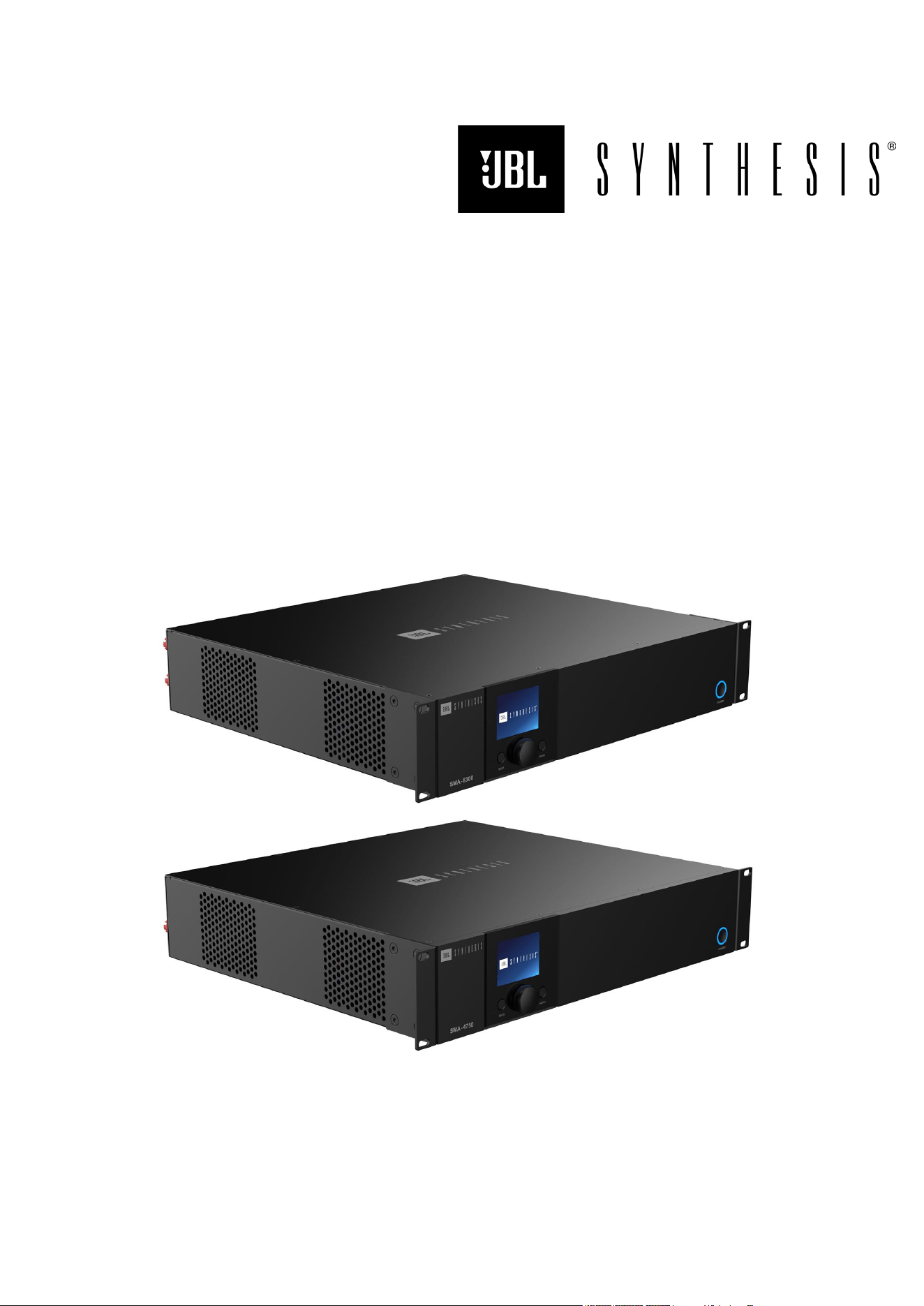
SMA-8300
SMA-4750
8 & 4-Channel Bridgeable Class D Amplifier
© 2025 Harman International Table of Contents 2
IMPORTANT Safety Instructions
1. Read these instructions.
2. Keep these instructions.
3. Heed all warnings.
4. Follow all instructions.
5. Do not use this apparatus near water.
6. Clean only with a dry cloth.
7. Do not block any ventilation openings. Install in accordance with the manufacturer’s instructions.
8. Do not install near any heat sources such as radiators, heat registers, stoves, or other apparatus (including amplifiers) that produce
heat.
9. Do not defeat the safety purpose of the polarized or grounding-type plug. A polarized plug has two blades with one wider than the other.
A grounding-type plug has two blades and a third grounding prong. The wide blade or the third prong is provided for your safety. If the
provided plug does not fit into your outlet, consult an electrician for replacement of the obsolete outlet.
10. Protect the power cord from being walked on or pinched, particularly at plugs, convenience receptacles, and the point where they exit
from the apparatus.
11. Only use attachments/accessories specified by the manufacturer.
12. Use only with a cart, stand, tripod, bracket, or table specified by the manufacturer, or sold with the apparatus. When a cart is used, use
caution when moving the cart/apparatus combination to avoid injury from tip-over.
13. Unplug this apparatus during lightning storms or when unused for long periods of time.
14. Refer all servicing to qualified service personnel. Servicing is required when the apparatus has been damaged in any way, such as
power-supply cord or plug is damaged, liquid has been spilled or objects have fallen into the apparatus, the apparatus has been
exposed to rain or moisture, does not operate normally, or has been dropped.
15. Use the mains plug to disconnect the apparatus from the mains. The mains plug inlet is the disconnect device for this product.
16. WARNING: TO REDUCE THE RISK OF FIRE OR ELECTRIC SHOCK, DO NOT EXPOSE THIS APPARATUS TO RAIN OR
MOISTURE.
17. DO NOT EXPOSE THIS EQUIPMENT TO DRIPPING OR SPLASHING AND ENSURE THAT NO OBJECTS FILLED WITH LIQUIDS,
SUCH AS VASES, ARE PLACED ON THE EQUIPMENT.
CAUTION
RISK OF ELECTRIC SHOCK. DO NOT OPEN.
THIS SYMBOL ON THE PRODUCT MEANS THERE IS UNINSULATED, DANGEROUS VOLTAGE WITHIN THE PRODUCT
ENCLOSURE THAT MAY PRESENT A RISK OF ELECTRICAL SHOCK.
THIS SYMBOL ON THE PRODUCT MEANS THERE ARE IMPORTANT OPERATING AND MAINTENANCE INSTRUCTIONS
IN THIS GUIDE.
Correct disposal of this product (Waste Electrical & Electronic Equipment)
This symbol means the product must not be discarded as household waste and should be delivered to an appropriate
collection facility for recycling. Proper disposal and recycling help protect natural resources, human health and the
environment. For more information on disposal and recycling of this product, contact your local municipality, disposal
service, or the shop where you bought this product.

© 2025 Harman International Table of Contents 3
Table of Contents
Safety Instructions ................................................................................................................................................... 2
Introduction ............................................................................................................................................................. 5
What’s in the Box ................................................................................................................................................. 5
Front Panel Overview .............................................................................................................................................. 6
Rear Panel Overview .............................................................................................................................................. 7
Installing the Amp .................................................................................................................................................... 8
Unpacking ............................................................................................................................................................ 8
Additional Materials ............................................................................................................................................. 8
Rack Mounting ..................................................................................................................................................... 8
Hardware Setup ...................................................................................................................................................... 9
Connecting The Ac Power Cord ........................................................................................................................... 9
Power Up Procedure ........................................................................................................................................... 9
Wiring Input Connectors .....................................................................................................................................11
Wiring Output Connectors ...................................................................................................................................11
Configuring the Amp Using the Front Panel Display ...............................................................................................12
Menu Structure ...................................................................................................................................................12
The Home Screen ...............................................................................................................................................13
Adjusting Channel Volume ..................................................................................................................................14
Input Source / Mixing ..........................................................................................................................................15
Input Setup .........................................................................................................................................................16
Input Sensitivity: ..............................................................................................................................................16
Input Gain: ......................................................................................................................................................16
Output Setup ......................................................................................................................................................17
Configuring Output Bridging ............................................................................................................................17
LoZ/HiZ Configuration .....................................................................................................................................17
Output Fader Linking .......................................................................................................................................18
Volume & Polarity ............................................................................................................................................18
Speaker Tunings .................................................................................................................................................19
DSP Setup ..........................................................................................................................................................20
Delay ...............................................................................................................................................................21
PEQ (Parametric EQ) ......................................................................................................................................22
Crossover ........................................................................................................................................................23
Limiter (LevelMAX™) ......................................................................................................................................24
Device Presets .......................................................................................................................................................25
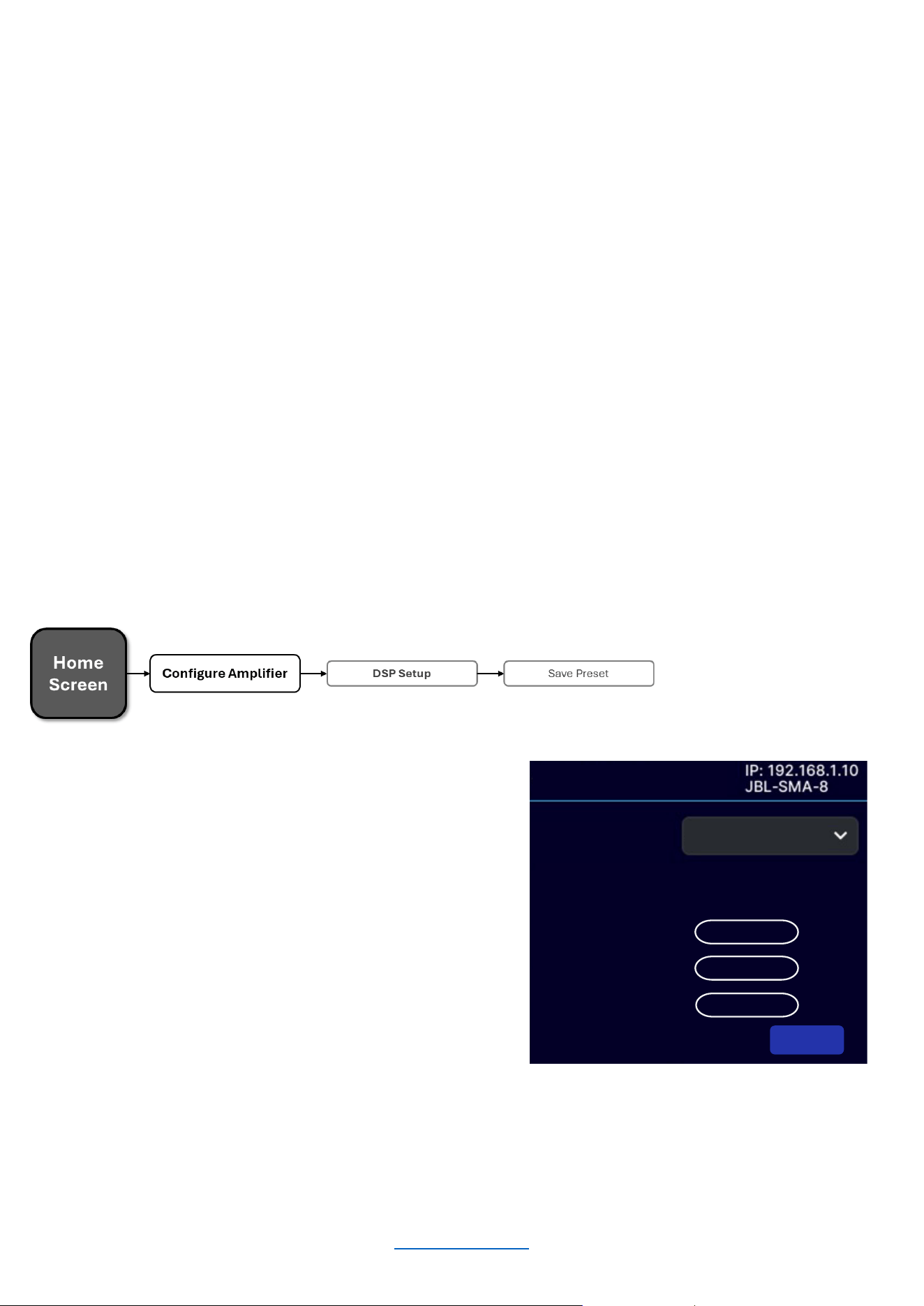
Save Preset ........................................................................................................................................................25
Load Preset ........................................................................................................................................................26
Application Examples .............................................................................................................................................27
Single-Ended Mode ............................................................................................................................................27

© 2025 Harman International Table of Contents 4
Bridge Mono Mode .............................................................................................................................................28
System Settings .....................................................................................................................................................29
Lighting / Display Options ...................................................................................................................................29
Security / Front Panel Lockout ............................................................................................................................29
Power Modes ......................................................................................................................................................30
Diagnostics .........................................................................................................................................................31
Network Settings ....................................................................................................................................................32
Dante / AES67 .......................................................................................................................................................33
Configuring The Amp Using the Web Client ...........................................................................................................34
Accessing The Web Client To Configure The Amplifier Over A Network .............................................................34
Monitor Page ......................................................................................................................................................34
Routing And Mixing .............................................................................................................................................35
Bridged Mode ..................................................................................................................................................35
Input ...................................................................................................................................................................36
DSP & Channel Selection................................................................................................................................36
Delay ...............................................................................................................................................................36
Setting the PEQ ..............................................................................................................................................37
Output & Tuning..................................................................................................................................................38
Output Monitor Section ....................................................................................................................................38
DSP ................................................................................................................................................................39
Setting the PEQ ..............................................................................................................................................39
Crossover ........................................................................................................................................................39
LevelMAX™ (Limiter) ......................................................................................................................................40
Speaker Tunings .............................................................................................................................................40
Settings ..............................................................................................................................................................41
Firmware Update Process ...............................................................................................................................42
Reset...............................................................................................................................................................44
Locking And Unlocking the Amplifier Using a PIN ...........................................................................................44
System Protection ..................................................................................................................................................46
Faults ..................................................................................................................................................................46
Universal Switching Power Supply ......................................................................................................................46
Troubleshooting .....................................................................................................................................................47
Specifications .........................................................................................................................................................48
SMA-8300 ...........................................................................................................................................................48
SMA-4750 ...........................................................................................................................................................49
Power Draw And Thermal ...................................................................................................................................50
Dimensions .........................................................................................................................................................51

© 2025 Harman International Table of Contents 5
Introduction
Congratulations, and thank you for purchasing a JBL Synthesis SMA series high-performance amplifier. The
SMA8300 & SMA-4750 amplifiers are designed, engineered, and manufactured to the industry’s highest quality
standards and provide cinema system integrators the advanced features and flexibility required for challenging,
21st-century cinema-sound applications.
Please take the time to study the owner’s manual so that you can obtain the best possible performance from your
amplifier. For more information and other languages, visit https://www.jblsynthesis.com/.
Should further assistance be required feel free to contact JBL Synthesis technical support at the numbers below.
Inside the US and Canada: +1 888.691.4171
Outside the US and Canada: +44 1707 668 012
What’s in the Box
1. JBL Synthesis SMA Amplifier
2. Quick-start guide and safety sheet
3. Rackmount brackets and fastening screws
4. AC Power Cord(s) – quantity and type vary by region
© 2025 Harman International Table of Contents 6
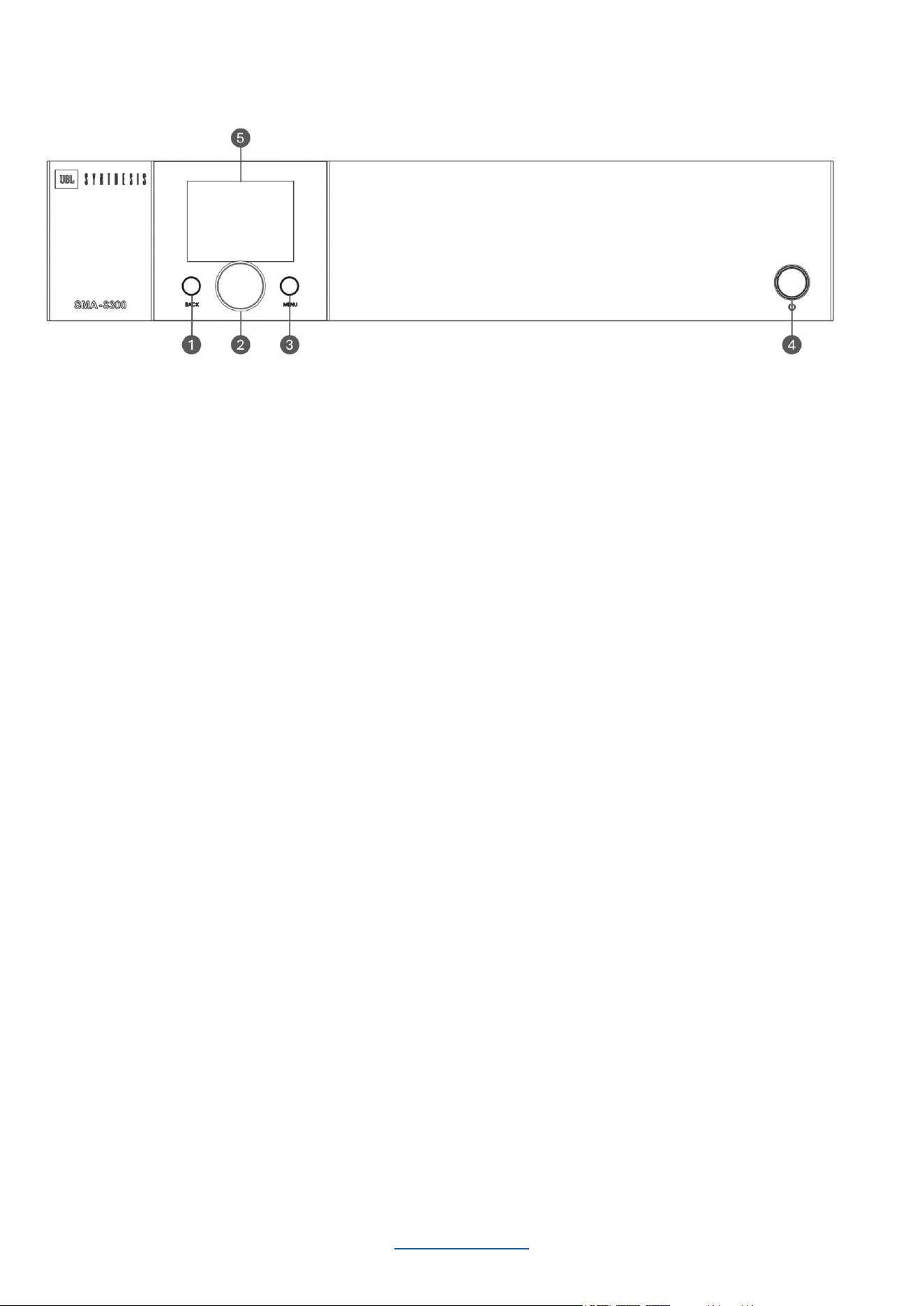
Front Panel Overview
1
BACK BUTTON
Press this button to navigate back one level
when navigating menus.
2
ENCODER
This encoder supports rotary and
pushbutton operation. It is used to navigate
the menus and select on-screen options. It
is also used to adjust individual channel or
overall system volume.
3
MENU BUTTON
Pressing this button will enter the Main
menu, where amplifier settings can be
edited.
4
STANDBY BUTTON
Turns the amplifier power on or off. The
Power button has an integrated power LED
that illuminates blue when the power is on
and red when the power is off.
5
LCD (DISPLAY)
This color LCD provides product information
and visual feedback for operating the
amplifier from the front panel.
© 2025 Harman International Table of Contents 7
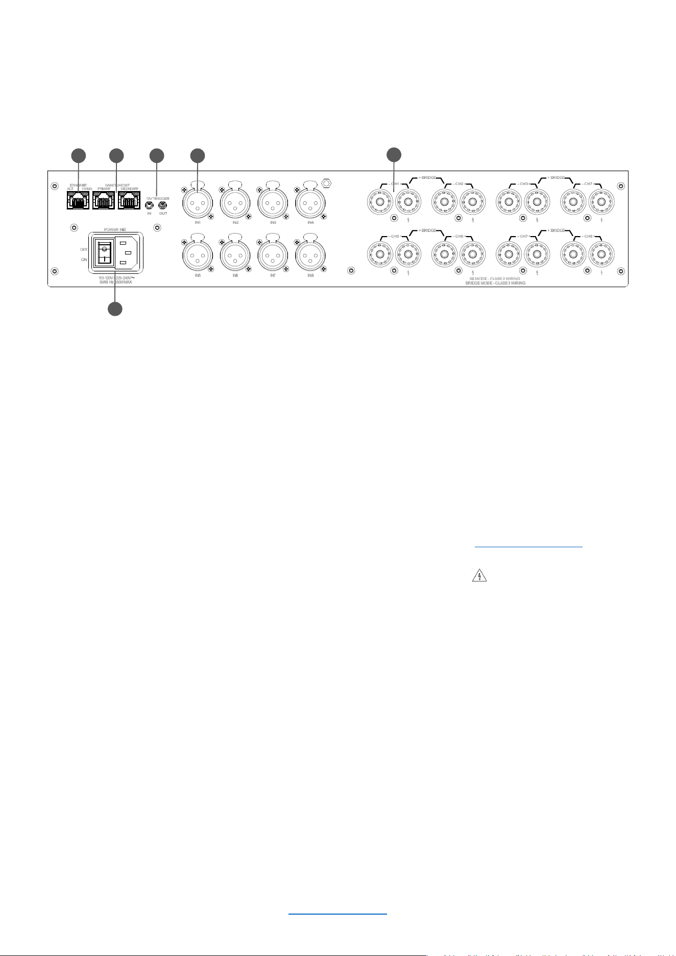
Rear Panel Overview
1
ETHERNET
(NETWORK CONTROL) PORT
Connect this RJ45 port to
a computer or network for
monitoring and controlling the
amplifier over Category 5e
wiring via the web client.
2
DANTE/AES67 PRIMARY &
SECONDARY PORTS
This implementation of DANTE/AES67
allows for up to 64 channels of digital
audio over Category 5e wiring.
3
AC POWER INLET
Connect the included AC power
cord to this standard 15A, IEC
type 320 inlet. Supported mains
voltage range is 100-240V~.
4
12V TRIGGER IN/OUT
Trigger In allows the amplifier to be turned
on or off by an external source.
Trigger Out allows the amplifier to control
the power state of other connected
equipment.
NOTE: Trigger Out is pass-thru only; the
amplifier does not supply a 12V signal on its
own.
5
ANALOG AUDIO INPUT
CONNECTORS
Connect your audio source
outputs to these inputs using balanced
analog XLR cables.
These inputs are high impedance,
balanced connections.
6
OUTPUT TERMINAL (BINDING POST)
CONNECTORS
Accepts up to 10 AWG wire, banana
connectors, or terminal forks. See the
“Wiring Output Connectors” section for
information on wiring these connectors.
NOTE: Custom wiring should only be
performed by qualified personnel. Class 2
output wiring is required in Single Ended
mode. Class 3 output wiring is required in
Bridge mono operation.
POWER INLET
11 0 -120V / 220-240V
50/60 Hz 550W MAX
12V TRIGGER
OUTIN
– CH6 +
+ BRID GE –
– CH5 + – CH8 +
+ BRID GE –
– CH7 +
– CH2 +
+ BRID GE –
– CH1 + – CH7 +
+ BRID GE –
– CH3 +
OFF
ON
IN5
IN6 IN7 IN8
IN1
IN2 IN3 IN4
DANTE/AES67
PRIMARY SECONDARY
ETHERNET
ACT 100Mb
SE MODE - CLASS 2 WIRING
BRIDGE M ODE - CLASS 3 WIRIN G
3
1 2 5
6
4
© 2025 Harman International Table of Contents 8
Installing the Amp
UNPACKING
Unpack your amplifier and inspect for any damage that may have occurred during transit. If damage is found, notify
the shipping company immediately. Only you can initiate a claim for shipping damage, though JBL will be happy to
help as needed. If the product arrived showing signs of damage, save the shipping carton for the shipper’s
inspection.
We also recommend that you save all packing materials for use if you ever need to transport the unit. Never ship
the unit without the factory carton and packing materials.
ADDITIONAL MATERIALS
For installation, you will need the following (not supplied):
• Input wiring cables
• Output wiring cables
• Phillips screwdriver
• Rack for mounting amplifier (or a stable surface for stacking)
• Category 5e or higher cabling
WARNING: Before you start to set up your amplifier, read and observe the Important Safety Instructions
included in the box. These instructions can also be downloaded from the product page at
www.jblsynthesis.com
CAUTION: Before you begin, make sure your amplifier is disconnected from the power source.
It is recommended that you mount the unit in a standard 19-inch (48.3 cm) equipment rack (EIA RS-310B). You
may also place a single amp on a solid, stable surface or stack multiple amps.
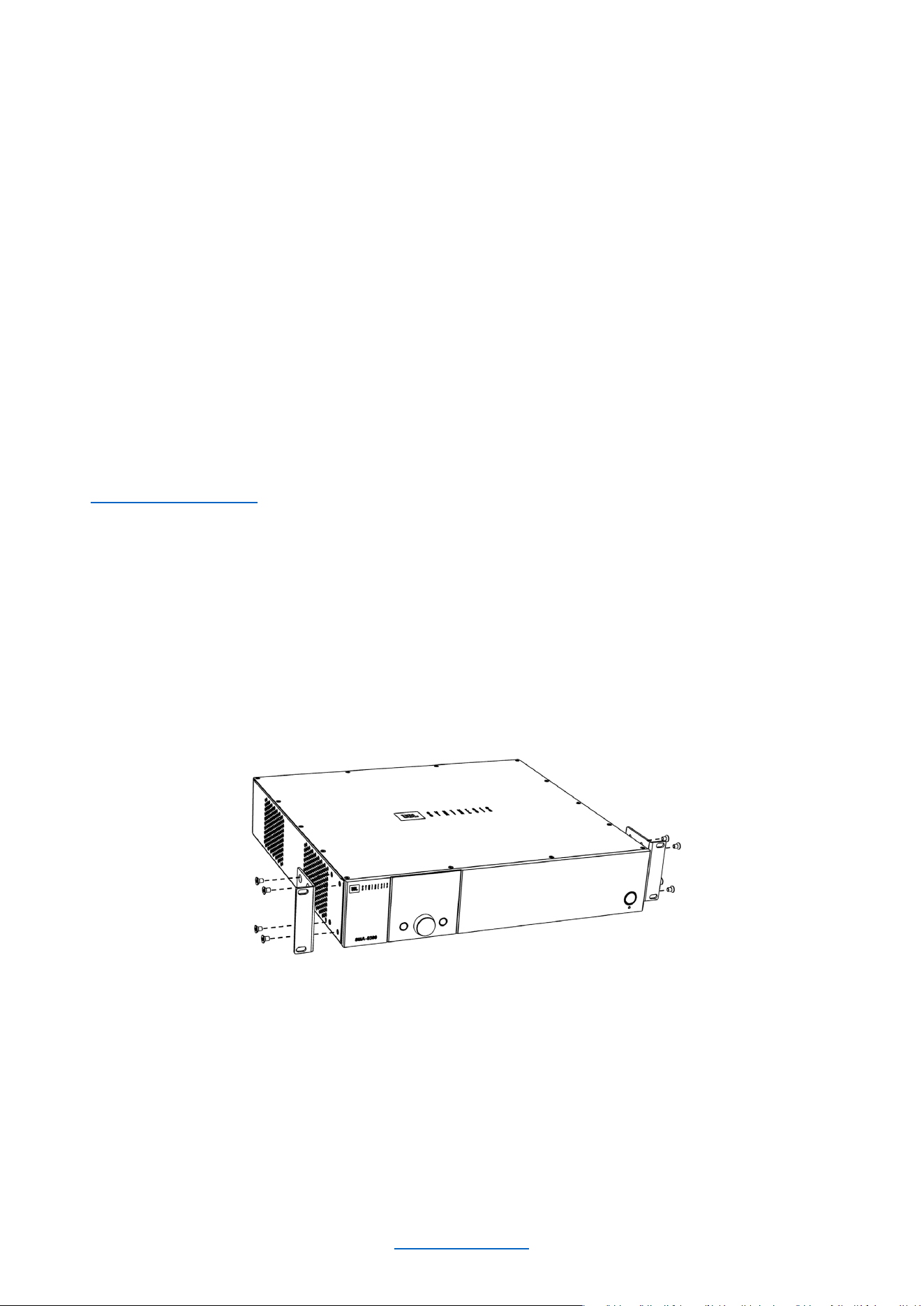
RACK MOUNTING
1. Attach the rack ear brackets to the sides of the amplifier using the provided machine screw fasteners into
the threaded holes (1 ± 0.1Nm recommended torque).
2. Install into rack and connect cabling.
PROPER COOLING
When using an equipment rack, mount units directly on top of each other. Close any spaces in the rack with blank
panels (open spaces will reduce cooling efficiency). Once mounted in the rack, ensure the sides of the amplifier
are well ventilated and that the fan openings are not obstructed, as air flow is side-to-side. The rack should be a
minimum of 2 inches (5.1cm) away from the sides of the amplifier. Ensure that the ambient temperature does not
exceed 45 degrees Celsius (113 Fahrenheit).

© 2025 Harman International Table of Contents 9
Hardware Setup
CONNECTING THE AC POWER CORD
Connect your amplifier to the AC mains power outlet using the supplied AC power cord. First, connect the IEC end
of the cord to the IEC connector on the amplifier. Then plug the other end of the cord to the AC mains.
The third (ground) prong of the supplied AC power cord connector is a required safety feature.
Do not attempt to disable this ground connection by using an adapter or other methods.
Make certain the AC mains voltage and current ratings are sufficient to deliver full power to all amplifiers. SMA
Series amplifiers use a universal power supply. The AC voltage requirements are 100V-240V~, 50/60Hz. If power
is lost, when power returns, the amplifier will automatically boot into the last known state.
POWER UP PROCEDURE
When turning on the amplifier for the first time:
1. Ensure all connections are disconnected (except the power cord).
2. Turn on the amplifier by using the rear AC mains rocker switch. The Power indicator will light blue and the
amplifier will boot as long as sufficient mains power is provided.
3. Configure the amplifier via the front panel display or the Web UI as described in this manual.
4. Once the amplifier has been properly configured for the application, turn off the power — by using the rear
AC mains rocker switch — then disconnect the power cord.
5. Turn down the level of your audio source.
6. Make all connections as described in “Wiring Input Connectors” and “Wiring Output Connectors.”
7. Once all connections have been made, reconnect the power cord and turn on the amplifier power.
8. Using the ENCODER, reduce the output volume of the amplifier to its minimum.
9. Turn your audio source up to an optimum level.
10. Now, increase the output volume of the amplifier to your liking.
11. Refer to all device meters and ensure that at no point in the signal chain is the signal being clipped in any
way. If any of the amplifier’s Clip indicators light yellow, reduce the source level until the RED clipping
meters no longer light.
12. Turn the amplifier’s ENCODER clockwise until the desired loudness or power level is achieved, while
making sure the amplifier’s clip LEDs do not light.
IMPORTANT: Always turn off the amplifier — by using the rear AC mains rocker switch — and disconnect
the power cord before making any wiring or installation changes.
IMPORTANT: When powering a fully configured Cinema system, always turn the amplifiers ON last and OFF first.

© 2025 Harman International Table of Contents 10
PRECAUTIONS
Your amplifier is protected from internal and external faults, but you should still take the following precautions for
optimum performance and safety:
1. Configure the amplifier for proper operation, including input and output wiring hookup. Improper wiring can
result in serious operating difficulties. For information on wiring and configuration, please consult "Wiring
Input Connectors" and "Wiring Output Connectors."
2. Use care when making connections, selecting signal sources, and controlling the output level.
3. Do not short the ground lead of an output cable to the input signal ground. This may form a ground loop
and cause oscillations.
Never connect the output to a power supply, battery, or power main Electrical shock may
result.
4. Tampering with the circuitry or making unauthorized circuit changes may be hazardous and invalidate all
agency listings.
5. Do not operate the amplifier with the Clip LEDs constantly flashing.
6. Do not overdrive the preamplifier/processor, which will cause clipped signal to be sent to the amplifier. Such
signals will be reproduced with extreme accuracy, and loudspeaker damage may result.
7. Do not operate the amplifier with less than the rated load impedance. Due to the amplifier’s output
protection, such a configuration may result in premature clipping and speaker damage.
REMEMBER: JBL/ HARMAN is not liable for damage that results from overdriving other system components.
© 2025 Harman International Table of Contents 11
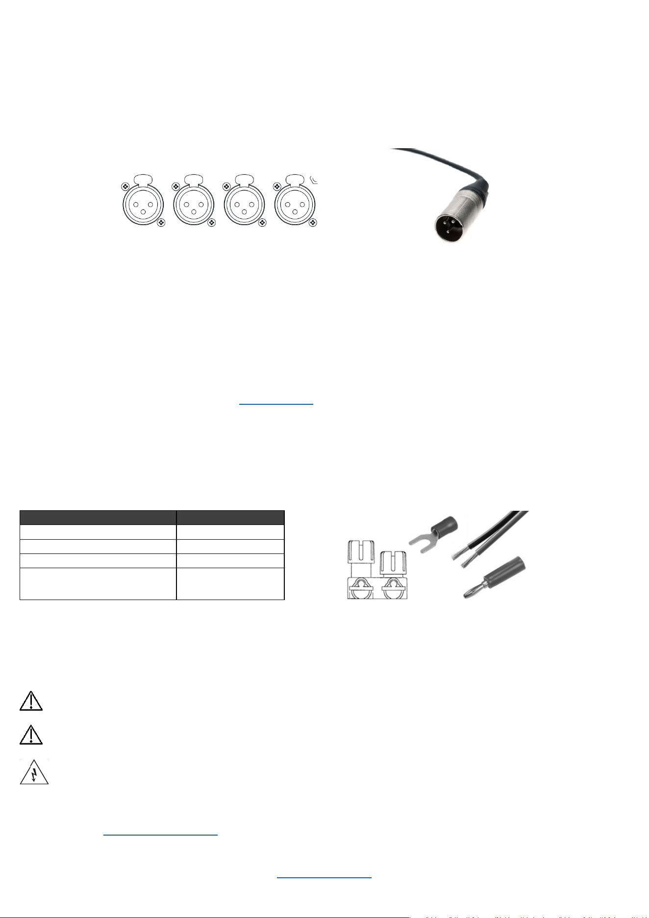
WIRING INPUT CONNECTORS
JBL Synthesis recommends using pre-built or professionally wired balanced cables (two-conductor plus shield).
Balanced wiring provides better rejection of unwanted noise and hum, however, an unbalanced line may also
be used.
The cables used for input at the amplifier side must be XLR male, as the amp input connectors are female.
The images below show the amplifier inputs and corresponding male XLR connector for balanced wiring.
This amplifier comes Dante Ready. To activate Dante, use the Dante Activator tool from Dante Controller software
(v4.5 or later). Once your device is discovered in the software, you will see your purchase options.
The primary and secondary RJ45 connectors are used to send/receive network audio channels.
WIRING OUTPUT CONNECTORS
Before making any output connections, ensure the power cord is disconnected from the amplifier and carefully
review the total impedance for loudspeakers connected to each amplifier output. If multiple loudspeakers are
connected to an output (i.e., in series, parallel, or series-parallel), be certain the total system impedance is within
allowed specification for the output. See "Specifications" for supported load specifications.
JBL Synthesis recommends using two-conductor or four-conductor, heavy gauge speaker wire. As shown in the
image below, you may use terminal forks, banana plugs, or bare wire up to 10 AWG for your output connectors
.
When using bare wire, JBL recommends that output wiring is tinned. To reduce strain on input and output wiring,
horizontal lacer bars such as the Middle Atlantic® part# LBP-4R90 are recommended.
Distance
Wire Size
Up to 25 ft. (7.6m)
16 AWG
26-40 ft. (7.9-12.2m)
14 AWG
41-60 ft. (12.5-18.3m)
12 AWG
> 60 ft (18.3m)
10 AWG
For low-impedance loads, refer to the table above and select the appropriate size of wire based on the distance
from amplifier to speaker.
CAUTION: Never use shielded cable for output wiring.
CAUTION: Never connect the speaker return to the chassis of the amplifier, or damage to the
amplifier may result.
NOTE: Custom wiring should only be performed by qualified personnel. Class 2 output wiring is
required in Single Ended mode. Class 3 output wiring is required in Bridge mono operation.
For application-specific output connection diagrams, including how to wire outputs for bridge mono
operation, see "Application Examples."
INPUT 1 INPUT
2
INPUT 3 INPUT 4
Amplifier Inputs
© 2025 Harman International Table of Contents 12
Configuring the Amp Using the Front Panel Display
The SMA amplifiers can be configured in two ways: via the Web UI, and via the front panel display. While both
methods are sufficient, setup using the Web UI is recommended as it tends to be more efficient.
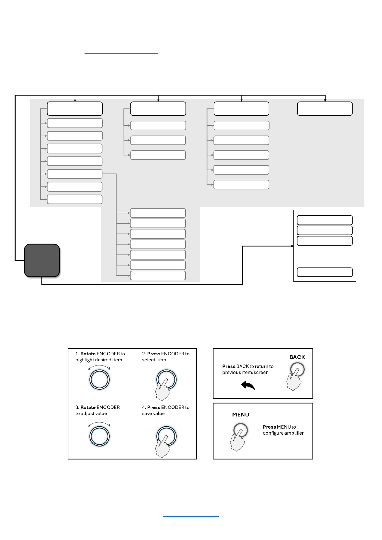
MENU STRUCTURE
This diagram shows the high-level SMA-8300 & SMA-4750 front panel menu structure.
Below is a general guide as to how to navigate the menu using the front panel display.
Home
Screen
Press MENU Button
Configure Amplifier
Input Setup
Output Setup
DSP Setup
Speaker Tunings
Save Preset
Load Preset
System Settings
Lighting/Display Options
Power Modes
Diagnostics
Network Settings
Mode
IP Address
Subnet Mask
Gateway
Save
Dante / AES
67
Input Source/Mixing
Input Delay
Input PEQ
Crossover
Output PEQ
Output Delay
Limiter
Rotate ENCODER and press to select channel/global volume
Channel 1 Volum e
Channel 2 Volum e
Global Volume
. . .
Channel 3 Volum e
Input Source/Mixing
© 2025 Harman International Table of Contents 13
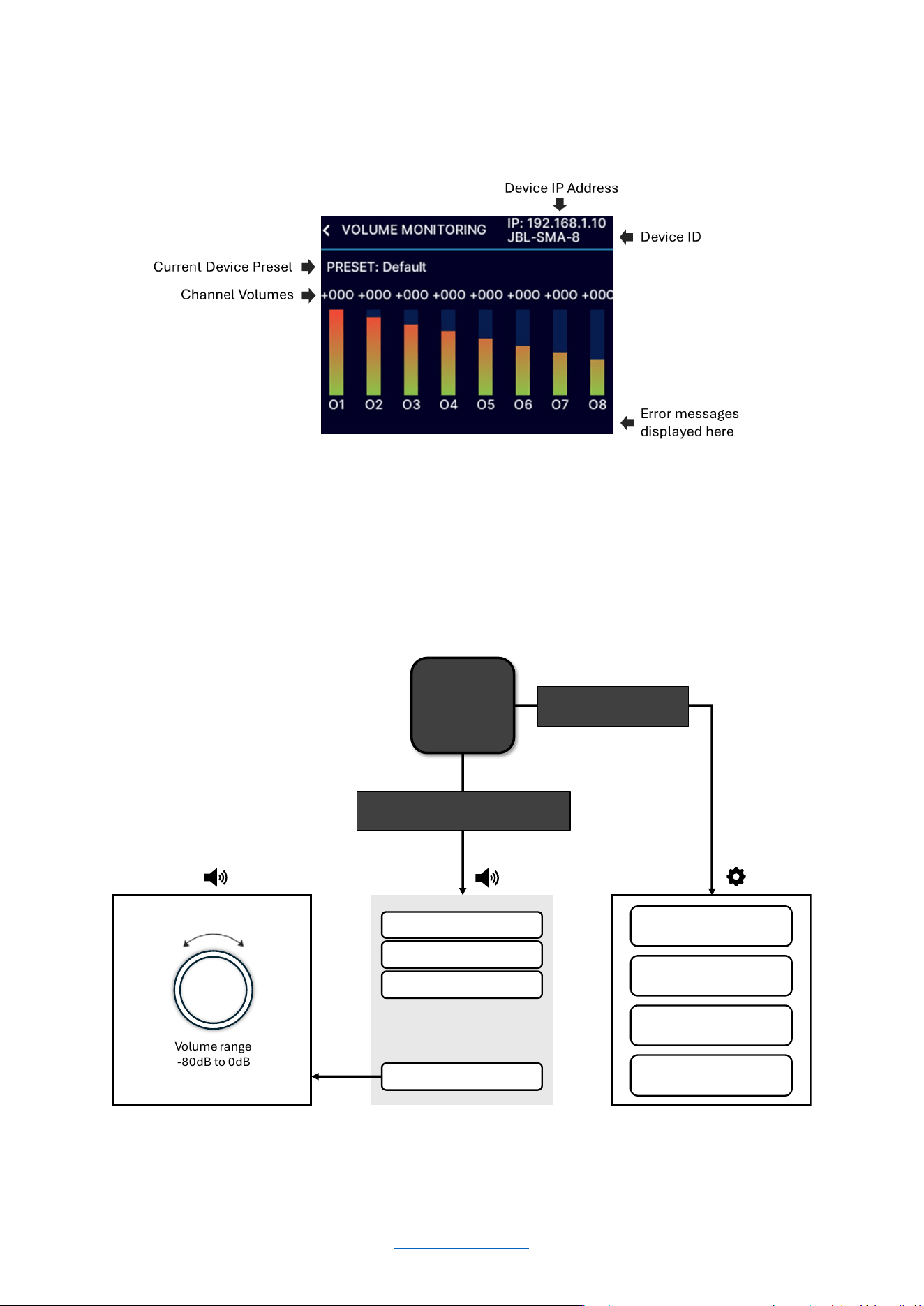
THE HOME SCREEN
The Home Screen (shown below) is the first screen displayed in the amplifier’s front panel display once the
amplifier has completed the boot sequence.
This diagram illustrates how to navigate the menu from the Home Screen using the front panel display.
Home
Screen
Volume range
-80dB to 0dB
Channel 1 Volume
Channel 2 Volume
Global Vo lu me
. . .
Channel 3 Volume
Rotate ENCODER and press to
select channel/master volume
Configure Amplifier
System Settings
Network Settings
Dante / AES67
Press MENU to
configure amplifier
© 2025 Harman International Table of Contents 14
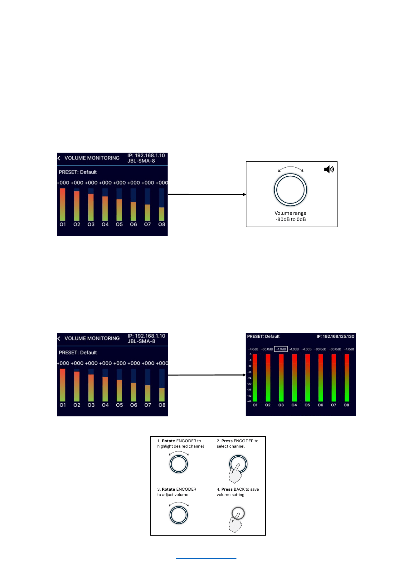
ADJUSTING CHANNEL VOLUME
Channel volume can either be controlled globally or independently per channel. The volume range is from -80dB to
0dB. The minimum/maximum global volume limits are governed by the channel with the highest or lowest volume
setting. For gain structure purposes, it is important to note that volume adjustment occurs at the end of the DSP
signal chain and before output limiting.
To adjust system (global) volume:
From the Home screen, turn the ENCODER until “all channels” are selected. Press the ENCODER, then rotate the
ENCODER to adjust the global (master) volume. The volume levels for all channels will be adjusted respectively.
To adjust the volume of a particular channel:
From the Home screen, rotate the ENCODER until the desired channel is highlighted. Press the ENCODER, then
rotate the ENCODER to adjust the individual channel volume.
Volume range
-80dB to 0dB
2. Press ENCODER to
select channel
1. Rotate ENCODER to
highlight desired channel
3. Rotate ENCODER
to adjust volume
4. Press BACK to save
volume setting
© 2025 Harman International Table of Contents 15
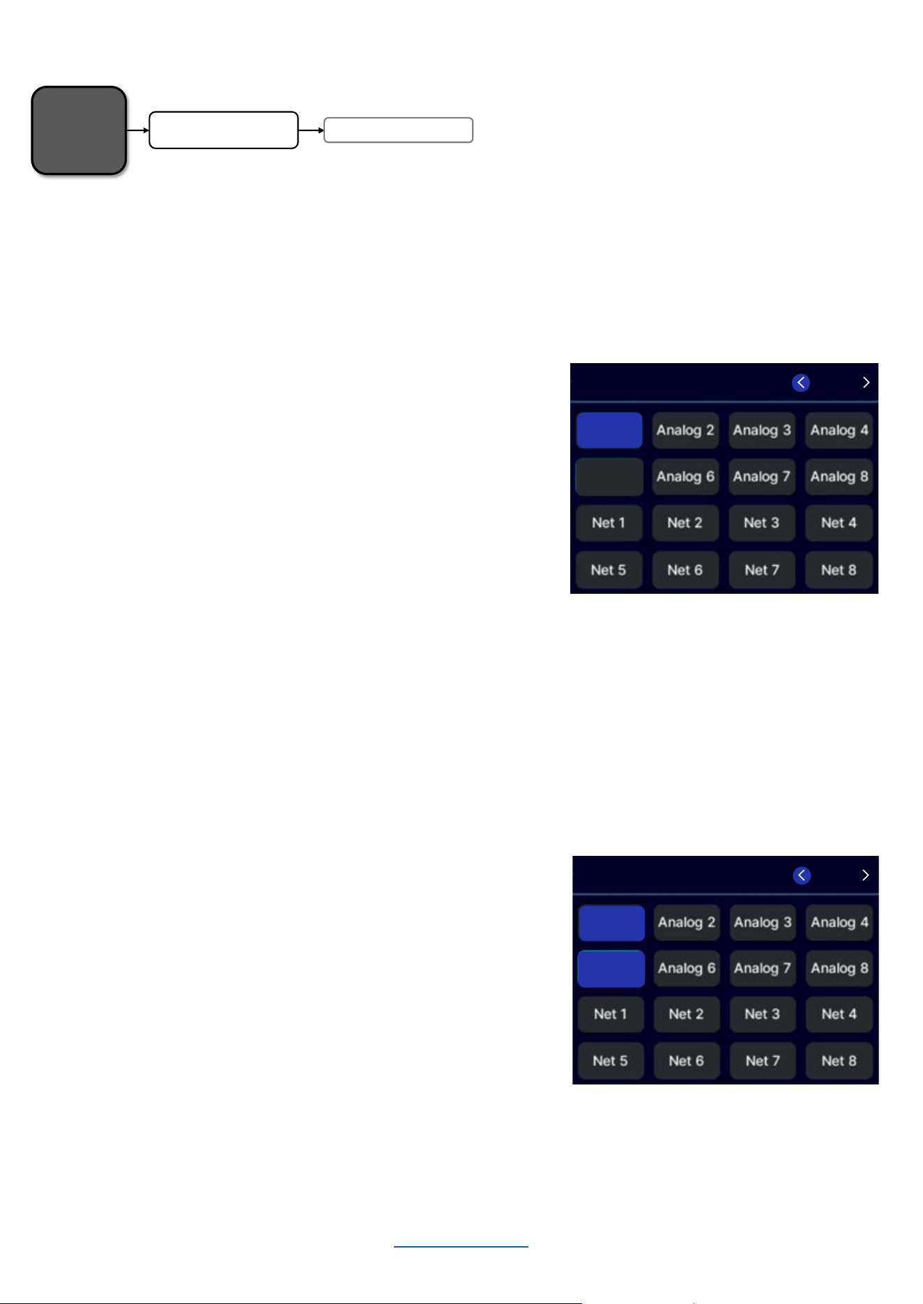
INPUT SOURCE / MIXING
The amplifiers ship from the factory with each output channel sourced from its respective analog input (analog
input 1 goes to output 1, analog input 2 goes to output 2, etc.).
To edit Input Source / Mixing settings:
• From the Home screen, press the MENU button.
• Select the "Configure Amplifier" option from the
menu using the ENCODER.
• Select the "Input Source/Mixing" option from the
menu.
• Turn the ENCODER to navigate to the desired input
channel and press the encoder to select.
• If a channel is already selected and you wish to
deselect it, navigate to it and press the encoder
• When finished, press the “BACK” button to exit the
menu.
If desired, one additional input channel can be assigned and consequently mixed to each output channel. Use the
same process to select an additional input channel to be mixed to one output channel. When performed
successfully, the front panel display will appear with two highlighted channels as shown below.
To add a 2
nd
input channel to an output channel:
• From the Home screen, press the MENU button.
• Select the "Configure Amplifier" option from the
menu using the ENCODER.
• Select the "Input Source/Mixing" option from the
menu.
• Turn the ENCODER to navigate to the desired
additional input channel and press the encoder to
select.
• When finished, press the “BACK” button to exit the
menu.
Home
Screen
Input Source / Mixing
Configure Amplifier
INPUT SOURCE
/MIXING
Analog 5
Analog
1
CH 1 / 8
INPUT SOURCE/MIXING
Analog 5
Analog 1
CH 1 / 8
© 2025 Harman International Table of Contents 16
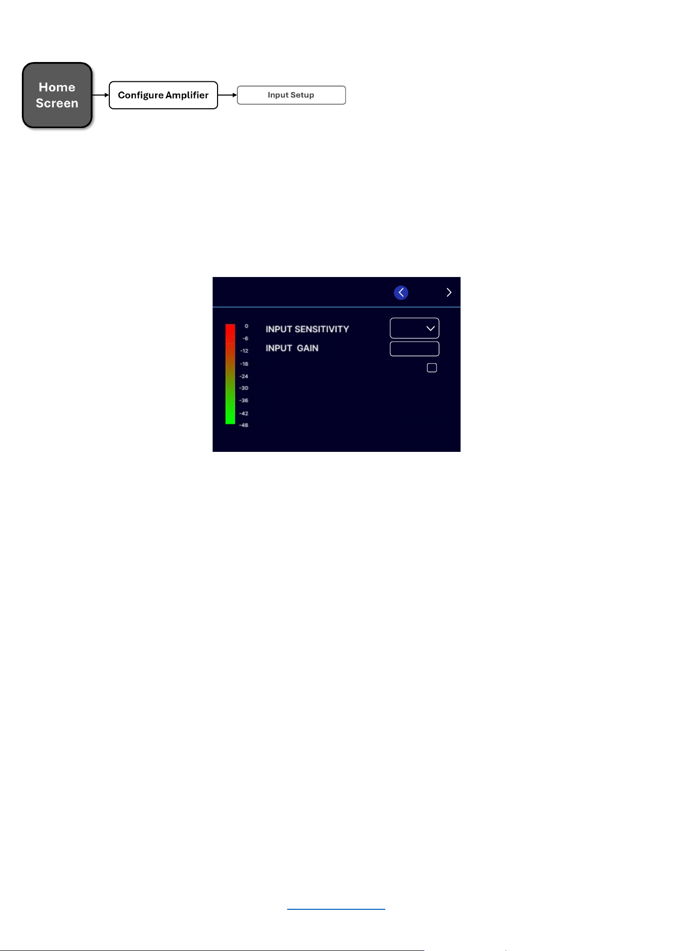
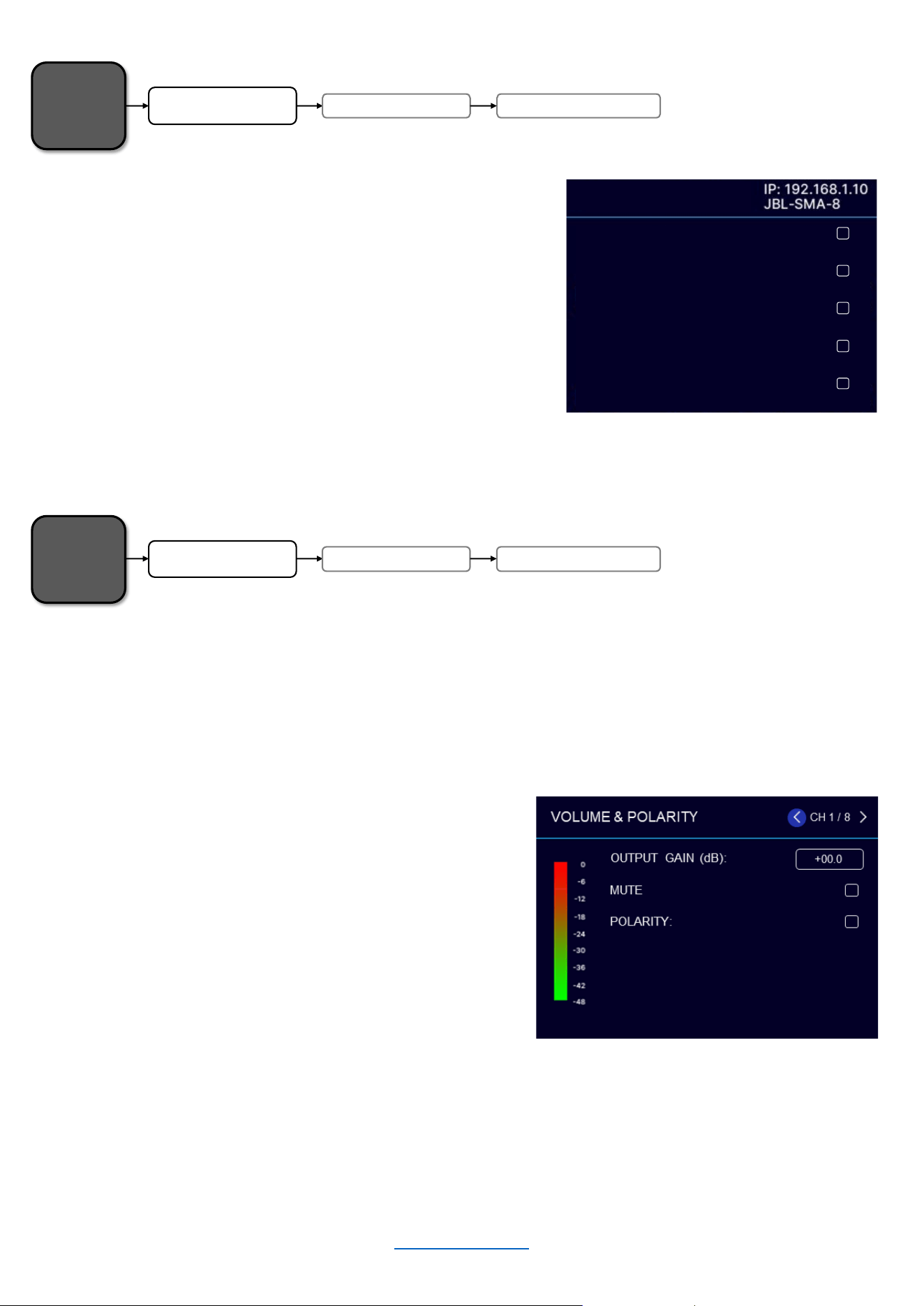
INPUT SETUP
Input sensitivity selects the input voltage level that’s required to generate a full-rated, amplified output. One way
that this feature may be used is to match input levels between balanced and unbalanced connections. Input Gain,
on the other hand, is used to make additional adjustments beyond what input sensitivity can do.
NOTE: Input settings will also affect Dante / AES67 signal flow.
Input Sensitivity:
• From the Home screen, press the MENU
button
• Select the "Configure Amplifier" option from
the menu using the ENCODER.
• Select the "Input Setup" option from the
menu using the ENCODER
• Scroll and select the channel at the top right
of the screen using the ENCODER
• Select the "Input Sensitivity" option from the
menu
• Turn the ENCODER to select the desired
input sensitivity (+4dBu, +10dBu, or +16dBu)
• Use the ENCODER to make the selection
• When finished, press the BACK button to
exit the menu
Input Gain:
• From the Home screen, press the MENU
button
• Select the "Configure Amplifier" option
from the menu using the ENCODER.
• Select the "Input Setup" option from the
menu using the ENCODER
• Scroll and select the channel at the top
right of the screen using the ENCODER
• Select the "Input Gain" option from the
menu
• Use the ENCODER to edit
• Press the ENCODER to make the
selection
• When finished, press the BACK button to
exit the menu
MUTE
10dBu
+00.0
CH 1 / 8
INPUT SETUP
© 2025 Harman International Table of Contents 17
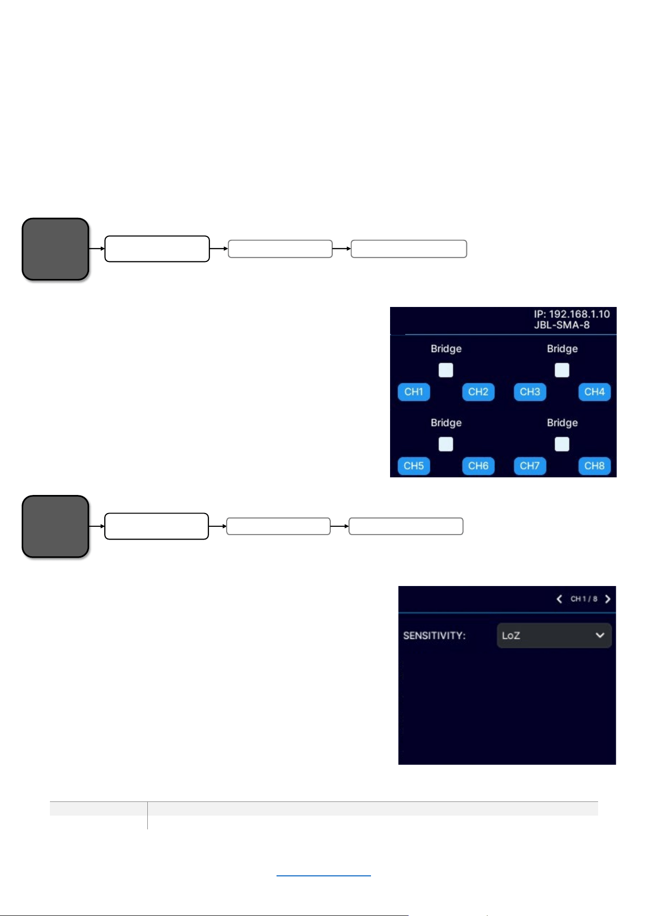
OUTPUT SETUP
SMA Series amplifiers are extremely capable and flexible. In the Output Setup menu, the following items can be
adjusted:
• Hi-Z/Low-Z on an individual channel basis (SMA-8300 must be bridged to support HiZ)
• 70Vrms or 100Vrms operation
• Channel assignments - Any input can be sent to any amplifier output
• Mono Bridge Output - Output pairs can be bridged for mono operation
• Output faders can be paired
• Volume & Polarity can be adjusted
Configuring Output Bridging
• From the Home screen, press the MENU button.
• Select the "Configure Amplifier" option from the
menu using the ENCODER.
• Select the "Output Setup" option from the menu
using the ENCODER.
• Use the ENCODER to select “Output Bridging”
• Use the ENCODER to navigate and engage the
bridging of adjacent amplifier output channels
LoZ/HiZ Configuration
• From the Home screen, press the MENU button.
• Select the "Configure Amplifier" option from the
menu using the ENCODER.
• Select the "Output Setup" option from the menu
using the ENCODER
• Use the ENCODER to select “LoZ/HiZ Configuration”
• Scroll and select the channel at the top right of the
screen using the ENCODER
• Use the ENCODER to select between LoZ and HiZ
MODEL
SINGLE-ENDED CONFIGURATION
BRIDGED CONFIGURATION
SMA-4750
LoZ / 70V
LoZ / 70V / 100V
SMA-8300
LoZ
LoZ / 70V / 100V
Home
Screen
Output Setup
Configure Amplifier
Output Bridging
LoZ/HiZ CONFIGURATION
OUTPUT BRIDGING
Home
Screen
Output Setup
Configure Amplifier
LoZ/HiZ Configuration
© 2025 Harman International Table of Contents 18
Output Fader Linking
• From the Home screen, press the MENU button
• Select the "Configure Amplifier" option from the
menu using the ENCODER.
• Select the "Output Setup" option from the menu
using the ENCODER
• Use the ENCODER to select “Output Fader Linking”
• Select which channel faders to link using the
ENCODER
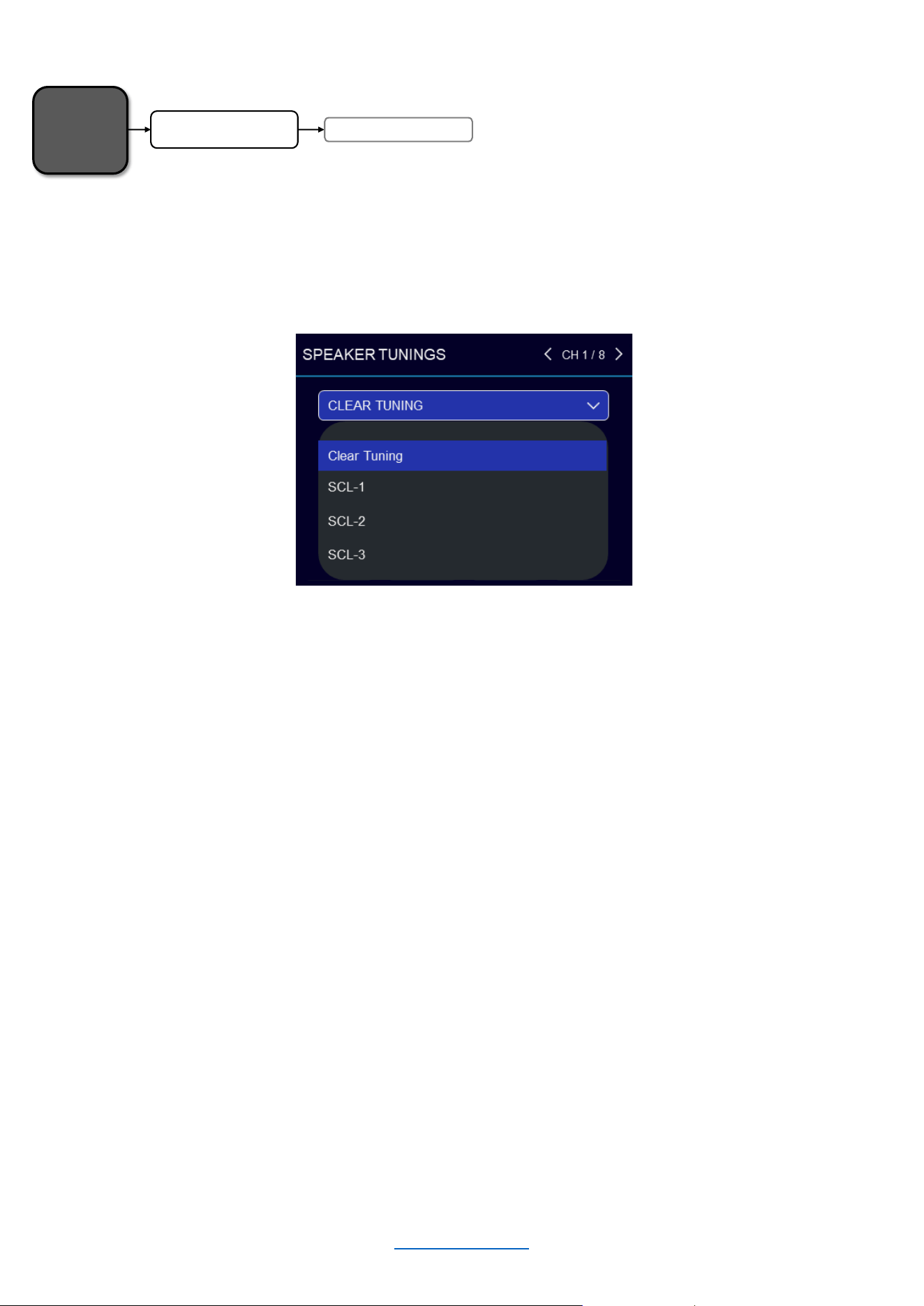
This screen allows for controlling individual channel output gain and mute, as well as the selection of inverted or
normal polarity.
Volume & Polarity
• From the Home screen, press the MENU button
• Select the "Configure Amplifier" option from the
menu using the ENCODER.
• Select the "Output Setup" option from the menu
using the ENCODER
• Use the ENCODER to select “Volume & Polarity”
• After selecting the channel, use the ENCODER to
select from the available parameters
• Press the ENCODER to change the state of a
checkbox
• Press the ENCODER and rotate to change the gain
Home
Screen
Output Setup
Configure Amplifier
Output Fader Linking
Home
Screen
Output SetupConfigure Amplifier Volu m e & Polarity
OUTPUT BRIDGING
OUTPUT FADER LINKING
Link Ch 1 and Ch 2:
Link Ch 2 and Ch 3:
Link Ch 3 and Ch 4:
Link Ch 4 and Ch 5:
Link Ch 5 and Ch 6:
© 2025 Harman International Table of Contents 19
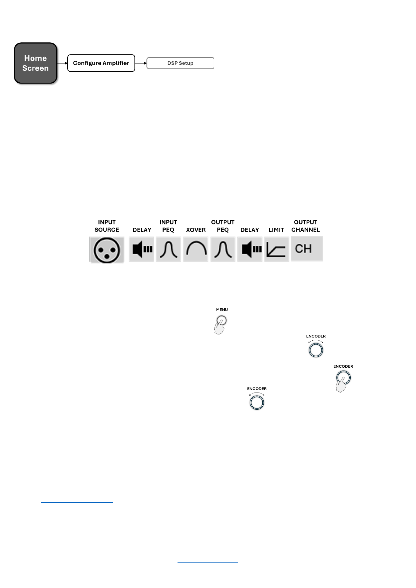
SPEAKER TUNINGS
Speaker tunings can be selected from the Speaker Tunings screen.
Speaker tunings apply DSP settings to a particular output channel, making it easy to optimize a speaker's
performance.
To select a speaker tuning for a channel:
• From the Home screen, press the MENU button
• Select the "Configure Amplifier" option from the menu using the ENCODER
• Use the ENCODER to select the "Speaker Tunings" option from the menu
• At the top of the screen, use the ENCODER to select the channel for which you wish to select a speaker
tuning
• A box will appear that reads “Clear Tuning”
• Press the ENCODER. A list of available speaker tunings will appear on the screen
• Use the ENCODER to navigate the list then press the ENCODER to select the matching speaker
series/model
• If applicable, additional prompts will appear to allow selection of the specific speaker model and additional
options
• Repeat for any additional channels
NOTE: For active bi-amp configurations with the JBL Synthesis SCL-1, please refer to the SCL-1 owner’s manual
Home
Screen
Speaker Tuning s
Configure Amplifier
© 2025 Harman International Table of Contents 20
DSP SETUP
From the DSP Setup menu, input level, PEQ, crossover, delay, and limiter settings can be adjusted to optimize the
loudspeaker performance. To easily optimize DSP settings for a particular JBL Synthesis Custom Loudspeaker
(SCL) model, see the “Speaker Tunings” section.
This screen shows the status of each DSP module (block). When a module is highlighted, it is enabled.
To edit DSP settings manually:
• From the Home screen, press the MENU button
• Select the "Configure Amplifier" option from the menu using the ENCODER
• Press the ENCODER to select the "DSP Setup" option from the menu
• Use the ENCODER to select the module you wish to edit
• Continue using the ENCODER to navigate, make selections, and edit settings
• When done, select "Done" at the bottom of the screen
NOTE: “Input Source / Mixing” is also accessible from the CONFIGURE AMPLIFIER screen.
© 2025 Harman International Table of Contents 21
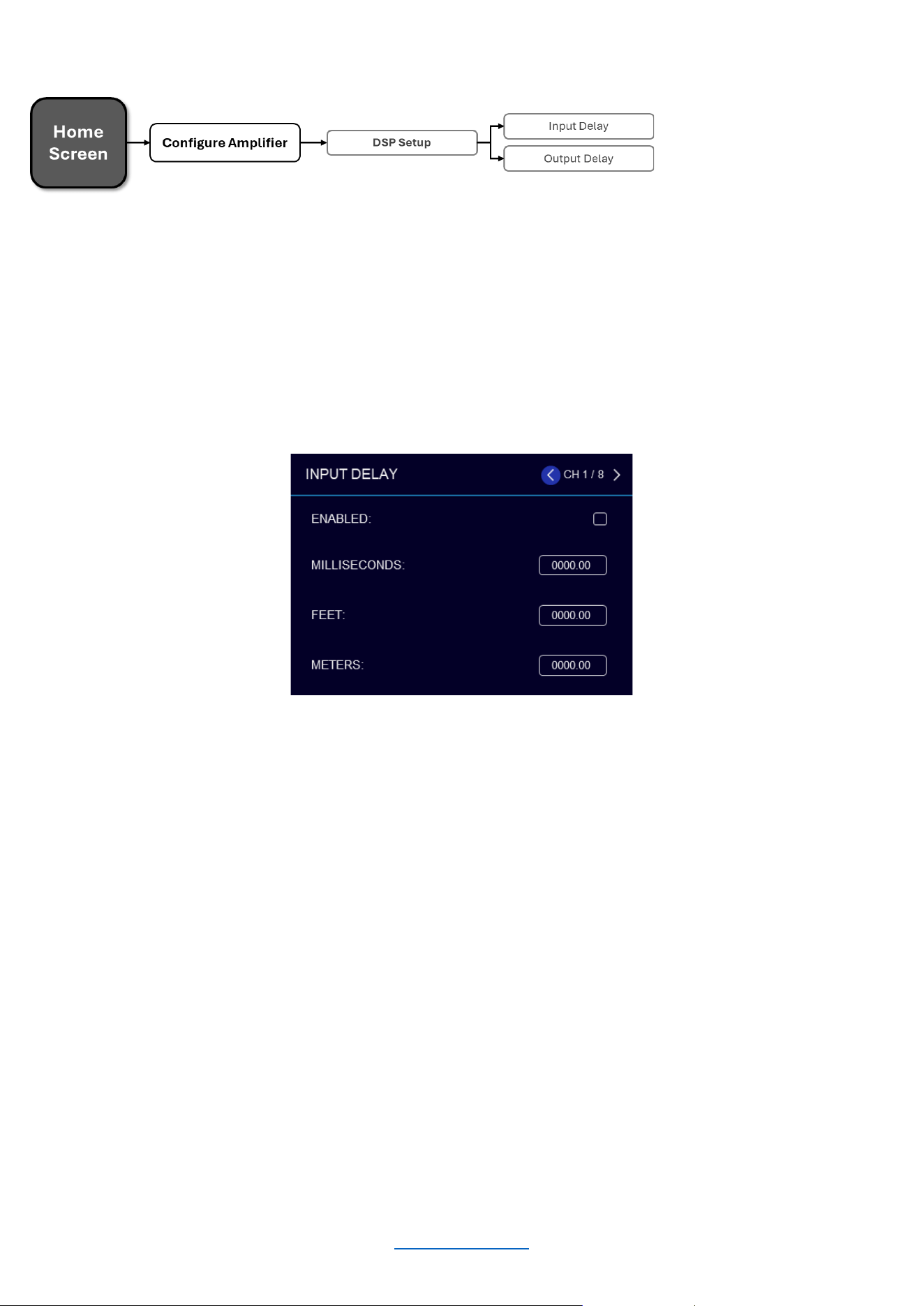
Delay
The amplifiers have an Input Delay (pre-crossover) and Output Delay (post-crossover) DSP module for each
channel.
The Output Delay can be used to time-align the various drivers in a multi-way speaker system or for close-
proximity zone delay (to compensate for the slap-delay artifacts caused when bleed from an adjacent channel is
audible). A total of up to 2000ms of delay time is available for each output channel.
The Input Delay can be used for delaying the system to the reference, or whenever more delay time is required
than the Output Delay has to offer. The Input Delays provide an additional 2 seconds of delay time for each
channel. Delay can be adjusted in milliseconds, feet, or meters.
To edit delay settings manually:
• From the Home screen, press the MENU button
• Select the "Configure Amplifier" option from the menu using the ENCODER
• Select the "DSP Setup" option from the menu
• Select the "Input Delay" or "Output Delay" icon for the channel you wish to edit
• Use the ENCODER to navigate, make selections, and edit settings
• When finished, press the “BACK” button to exit the menu
Available options/parameters:
• Enable (Off, On)
Turns the Delay on or off
• Seconds (Input Delay: 0 – 2000ms, Output Delay: 0 – 2000ms)
Adjusts the delay time in ms.
• Feet (Input Delay: 0 – 2250ft, Output Delay: 0 – 2250ft)
Adjusts the delay time in fee.
• Meters (Input Delay: 0 – 646m, Output Delay: 0 – 646m)
Adjusts the delay time in meters
© 2025 Harman International Table of Contents 22
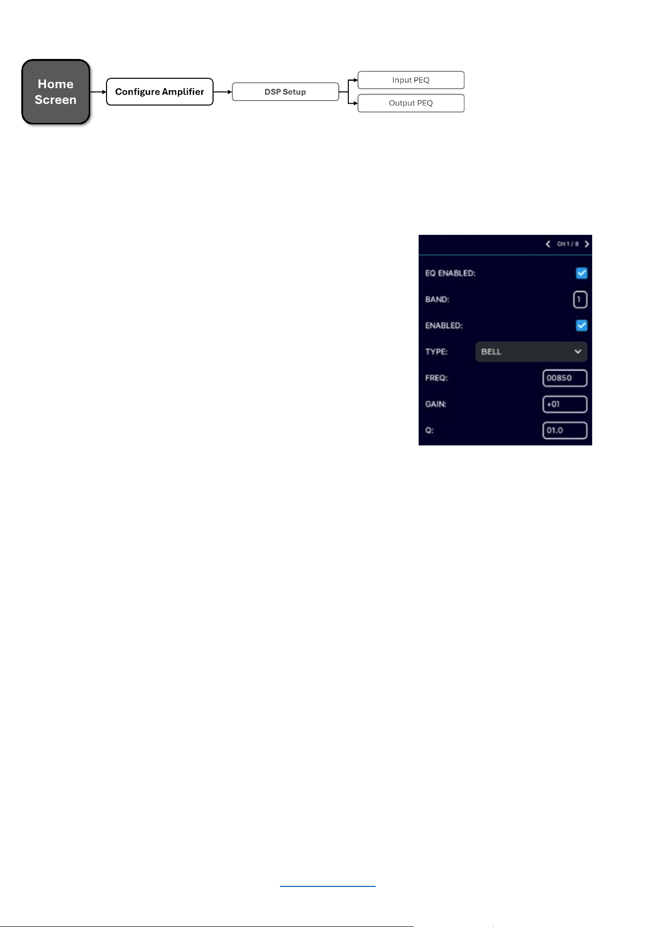
INPUT PE Q
PEQ (Parametric EQ)
Input and Output PEQs are available. Each PEQ section contains 8 configurable biquads. The Output (post-
crossover) PEQs are typically used for speaker tuning settings, and the Input (pre-crossover) PEQs provide
additional EQ filtering for the system if required.
To edit PEQ settings manually:
• From the Home screen, press the MENU button.
• Select the "Configure Amplifier" option from the menu
using the ENCODER.
• Select the "DSP Setup" option from the menu.
• Select the pre or post-crossover "PEQ" icon for the
channel you wish to edit.
• Use the ENCODER to navigate, make selections, and
edit settings.
• When finished, press the “BACK” button to exit the
menu.
Available options/parameters:
Enable (Off, On)
Turns the PEQ on or off.
Band (Band 1 – Band 8)
Selects the filter band for editing.
Type
Selects the type of filter for the band.
Frequency (20Hz – 22kHz)
Sets the center/corner frequency of the band.
Gain (±20dB)
Sets the amount of gain (boost/cut) applied to the band.
Q (0.10 – 10)
Sets the Q of the band for Bell-type filters or adjusts the resonant peak for 2nd Order low-pass/high-pass
filters (only visible when one of these filter types is selected).
Available filter types:
• Bell
• Low-shelf
• High-shelf
• LP 1
st
Order (6dB/oct low-pass filter)
• HP 1
st
Order (6dB/oct high-pass filter)
• LP 2
nd
Order (6-12dB/oct low-pass filter with variable resonant peak using the Q parameter)
• HP 2
nd
Order (6-12dB/oct high-pass filter with variable resonant peak using the Q parameter)
• All-pass 1
st
Order (90º phase shift)
• All-pass 2
nd
Order (180º phase shift)
© 2025 Harman International Table of Contents 23
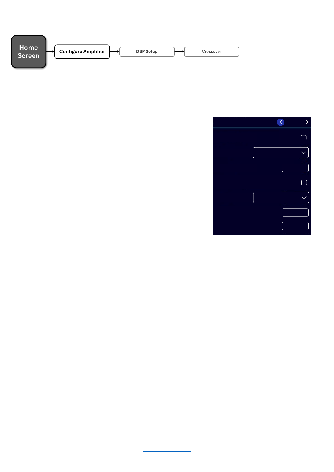
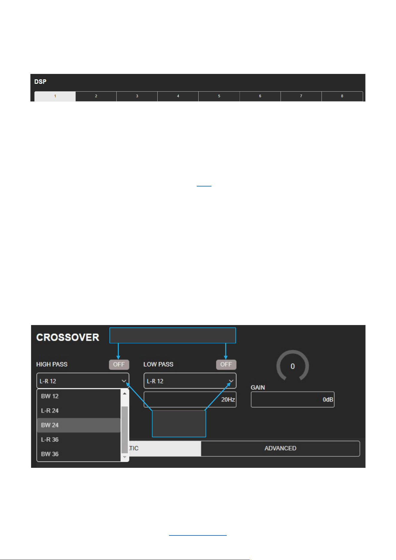
Crossover
Crossover filter settings can be edited from the Crossover screen. Crossover filters are used to restrict the range of
frequencies sent to a loudspeaker or driver for protection and sound optimization.
To edit crossover settings manually:
• From the Home screen, press the MENU button.
• Select the "Configure Amplifier" option from the menu
using the ENCODER.
• Select the "DSP Setup" option from the menu.
• Select the "XOVER" icon for the channel you wish to
edit.
• Use the ENCODER to navigate, make selections, and
edit settings.
• When finished, press the “BACK” button to exit the
menu.
Available options/parameters:
HP Enable (Off, On)
Enables or disables the high-pass filter
HP Type (Butterworth 12 – 24 – 36dB/octave, Linkwitz-Riley 12 – 24 – 36dB/octave )
Selects the high-pass filter type and slope rate in dB/octave
HP Freq (20Hz – 20kHz)
Sets the high-pass filter corner frequency
LP Enable (Off, On)
Enables or disables the low-pass filter
LP Type (Butterworth 12 – 24 – 36dB/octave, Linkwitz-Riley 12 – 24 – 36dB/octave)
Selects the low-pass filter type and slope rate in dB/octave
LP Freq (20Hz – 20kHz)
Sets the low-pass filter's corner frequency
Gain (-80 to 24dB)
Adjusts the crossover output gain, pre limiter
Polarity (Normal, Inverted)
Selects between normal or inverted polarity for the selected output
HP TY PE :
L-R 12
HP FREQ : 00020
LP ENA BL E
D
LP TY PE : L-R 12
LP FREQ : 00020
GA IN
+00
HP ENA BL ED :
CH
1 / 8
OUTPUT CROSSOVER
© 2025 Harman International Table of Contents 24
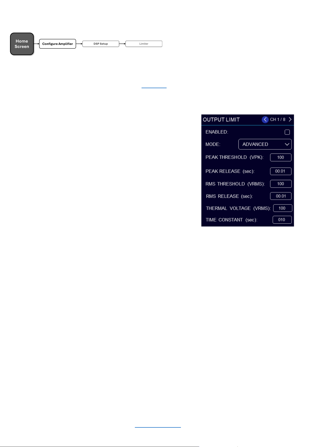
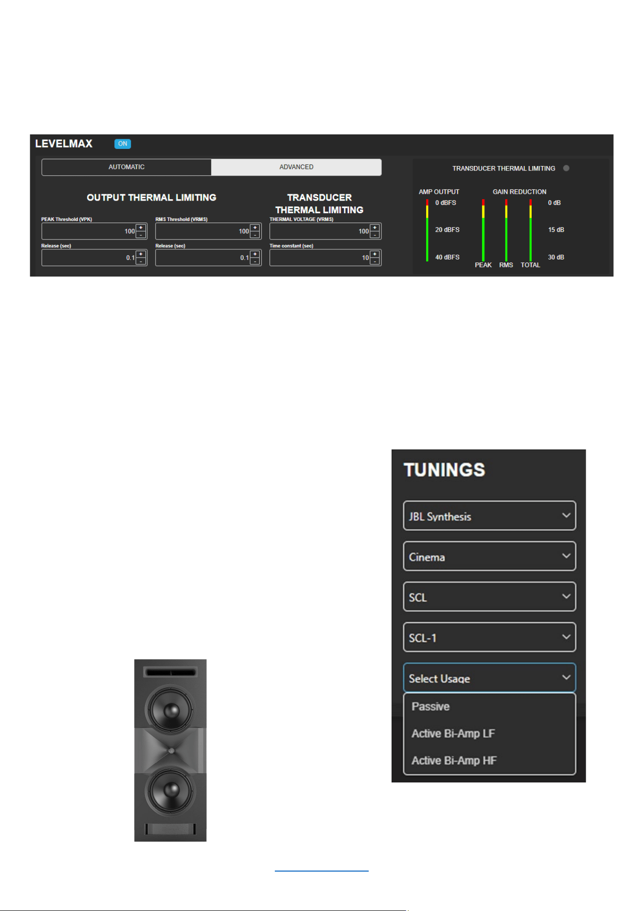
Limiter (LevelMAX™)
Limiters are used to set a "ceiling" on the output level to protect drivers from over-excursion. The thermal limiters in
the amplifiers can also protect against thermal driver failure (overheating). For advanced users, LevelMAX can be
configured manually using the information found in this guide. If you are not already familiar with how to configure
the parameters in the figure below, it is NOT recommended that you configure LevelMAX manually.
To edit limiter settings manually:
• From the Home screen, press the MENU button
• Select the "Configure Amplifier" option from the menu
using the ENCODER
• Select the "DSP Setup" option from the menu
• Select the "Limit" icon for the channel you wish to edit
• Use the ENCODER to navigate, make selections, and
edit settings
• When finished, press the “BACK” button to exit the
menu
Available options/parameters:
Enable (Off, On)
Turns the Limiter on or off
Mode (Automatic, Advanced)
Sets the operation mode. In automatic mode, the software determines the best settings based on the signal
characteristics
RMS Voltage (1 – 200VRMS)
Sets the RMS voltage limit for the output
Thermal Voltage (1 – 200V)
Sets the long-term output power limit of the amplifier to what the loudspeaker load can handle without
overheating and going into thermal compression. This is based on the AES power/voltage ratings of drivers
outlined in the AES2-2012 standard
Time Constant (1 – 600 sec)
Sets the time it takes for the thermal limiter to adjust output voltage. This is based on the AES
power/voltage ratings of drivers outlined in the AES2-2012 standard
© 2025 Harman International Table of Contents 25
Device Presets
Device presets allow configuration, DSP, channel assignment, gains, and other settings to be stored for later
recall. A device preset can be used to configure the amp for a specific application and speaker model. For
example, you may wish to use one device preset that optimizes the DSP settings for a JBL Synthesis bi-amplified
speaker whilst using another preset for a pair of loudspeakers with different characteristics. Subtle changes can
also be made between device presets, such as a change of input channel assignments. Device presets can be
stored within the amplifier as well as backed up to a PC using the web client.
DEFAULT is the factory default device preset and cannot be overwritten. It sets up the amplifier for pass-thru
operation with no DSP features enabled. Presets 1-20 are user device presets and can be overwritten.
The following bullets outline which settings are stored to device presets and which are not:
Settings Stored to Device Presets
• DSP Settings
• Levels
• Mutes
• Internal Amp Wiring (channel assignment, dual-
mono/bridge mode)
• Input Source Assignments (analog and network)
Settings NOT Stored to Device Presets
• Front Panel Lighting/Display Options
• Front Panel Security
• Network Settings
SAVE PRESET
To save the current settings as a device preset from the
front panel:
• From the Home screen, press the MENU button
• Select the "Configure Amplifier" option from the menu
using the ENCODER
• Select the Preset ID to which you wish to save the
preset
• Select the "Save" option
• Select "YES"
NOTE: Any unsaved settings will be retained in the amplifier after a power cycle. However, settings should be
saved before loading another device preset if you wish to recall them later. Otherwise, they will be lost.
Default
ENABLE ON NETWORK INPUTS:
AUTO -STANDBY TIMEOUT (mins)
60
AUTO -STANDBY
THRESHOLD
SAVE PRESET
PRESET:
Last applied preset:’Default ’
Changes made since last apply
:
yes
Analog In 1
0.0dB CH1NO TUNING
Analog In 2 0.0dB CH2
NO TUNING
Analog In… 0.0dB
CH…
NO TUNING
SAVE
© 2025 Harman International Table of Contents 26
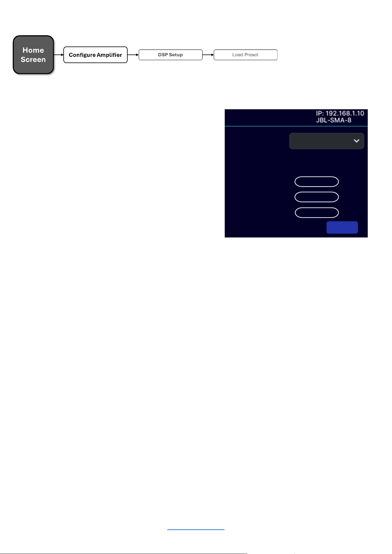
LOAD PRESET
To load a device preset from the front panel:
• From the Home screen, press the MENU button
• Select the "Configure Amplifier" option from the
menu using the ENCODER
• Select the "Load Preset" option
• Use the ENCODER to navigate presets. As each
preset is selected, the preset number, name, and
configuration will be displayed on-screen
• Once the desired preset has been selected, use the
ENCODER to select "LOAD"
Default
ENABLE ON NETWORK INPUTS:
AUTO -STANDBY TIMEOUT
(mins)
60
AUTO -STANDBY
THRESHOLD
LOAD PRESET
PRESET:
Last applied preset:’Default ’
Changes made since last apply:yes
Analog In 1
0.0dB CH1NO TUNING
Analog In 2 0.0dB CH
2
NO TUNING
Analog In… 0.0dB
CH
…
NO TUNING
LOAD
© 2025 Harman International Table of Contents 27
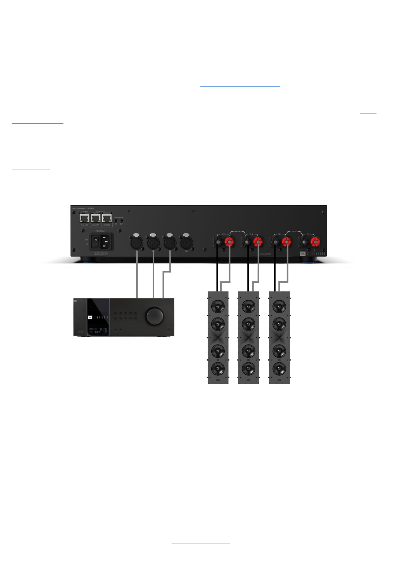
Application Examples
SINGLE-ENDED MODE
Typical input/output wiring is shown in the image below.
INPUTS: Connect the input wires for each channel. See "Wiring Input Connectors" for further information on
analog input wiring.
If an input signal is intended to drive multiple outputs, it can be routed as such using the procedure in the “Input
Source / Mixing” section.
OUTPUTS: Be sure to maintain proper polarity (+/–) between the amplifier terminals and the speakers. Connect
the positive (+) lead of the Channel 1 speaker to the positive (+) terminal of Channel 1 of the amp. Repeat this
process for the negative (–) lead. Repeat for all remaining speakers that will be in use. See "Wiring Output
Connectors” for additional information on output wiring.
System Wiring in Single-Ended Mode
NOTE: Always route the input and output wires in separate bundles.
© 2025 Harman International Table of Contents 28
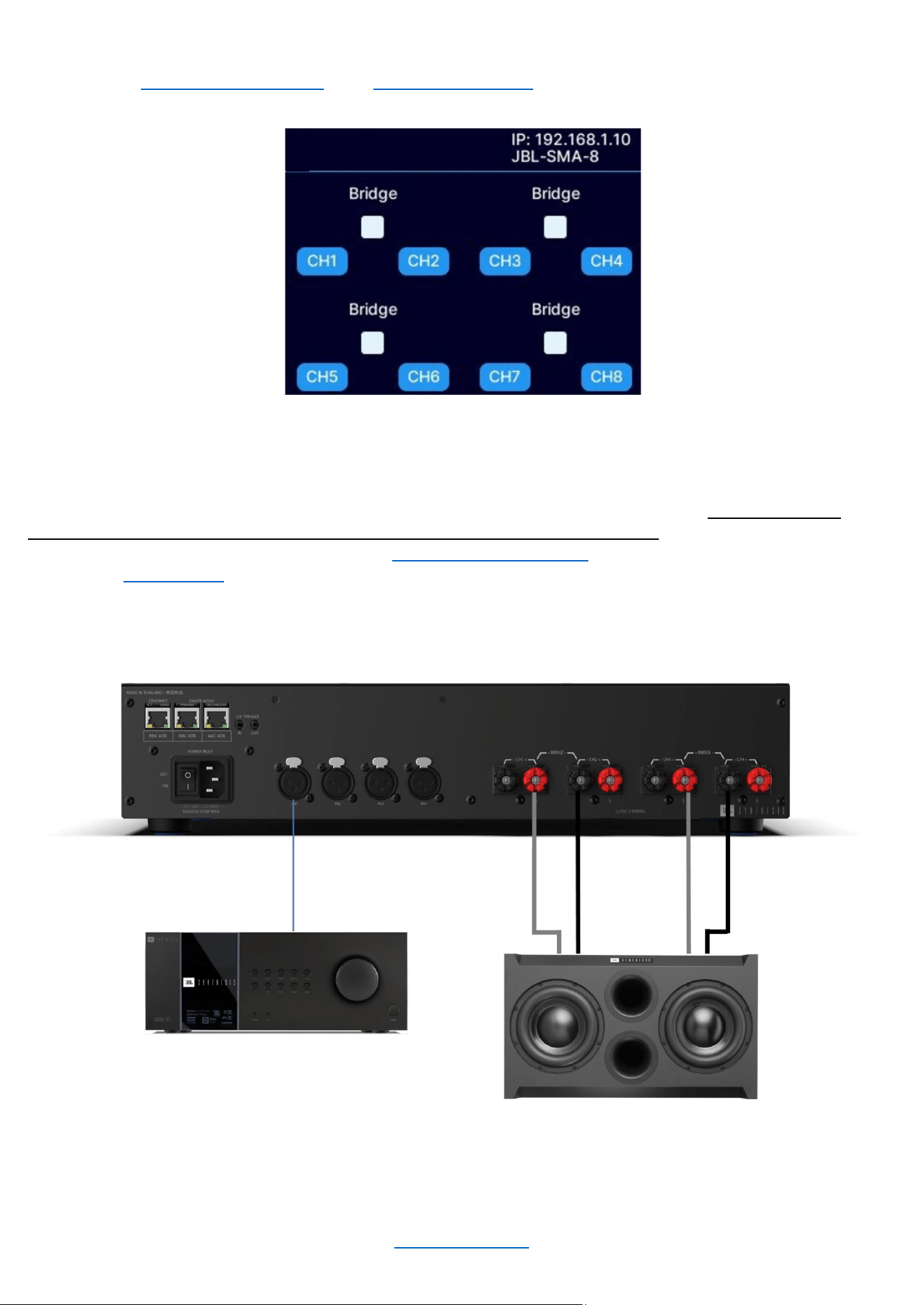
BRIDGE MONO MODE
INPUTS: See “Wiring Input Connectors” and “Input Source / Mixing” for further information on analog input wiring.
Front panel amplifier mode settings
OUTPUTS: Be sure to maintain proper polarity (+/–) between the amplifier terminals and the speakers. Connect
the positive (+) lead of Speaker 1 to the positive (+) terminal of Channel 1 of the amplifier. Next, connect the
negative (–) lead of Speaker 1 to the negative (–) lead of Channel 2 of the amplifier. Repeat for all remaining
speakers that will be used in bridge mode. See “Wiring Output Connectors” for additional information on output
wiring. See "Output Setup" for information on configuring an output pair for bridge mono operation.
System Wiring in Bridge Mono Mode (JBL Synthesis SSW-1 shown)
NOTE: Always route the input and output wires in separate bundles.
OUTPUT BRIDGING
© 2025 Harman International Table of Contents 29
System Settings
LIGHTING / DISPLAY OPTIONS
These options can be used to turn off the front panel LCD.
To Edit Lighting Options:
• From the Home screen, press the MENU button
• Select the “System Settings” option from the menu
using the ENCODER
• Select "Lighting/Display Options" from the menu
• Scroll and select the setting using the ENCODER
• When done, press the BACK button to exit this menu
Available options/parameters:
• LCD Display (Always On, 30 sec, 5 min, 30 min)
This option allows the LCD to go to sleep after a specified period of inactivity. Once asleep, any button
press will wake up the LCD
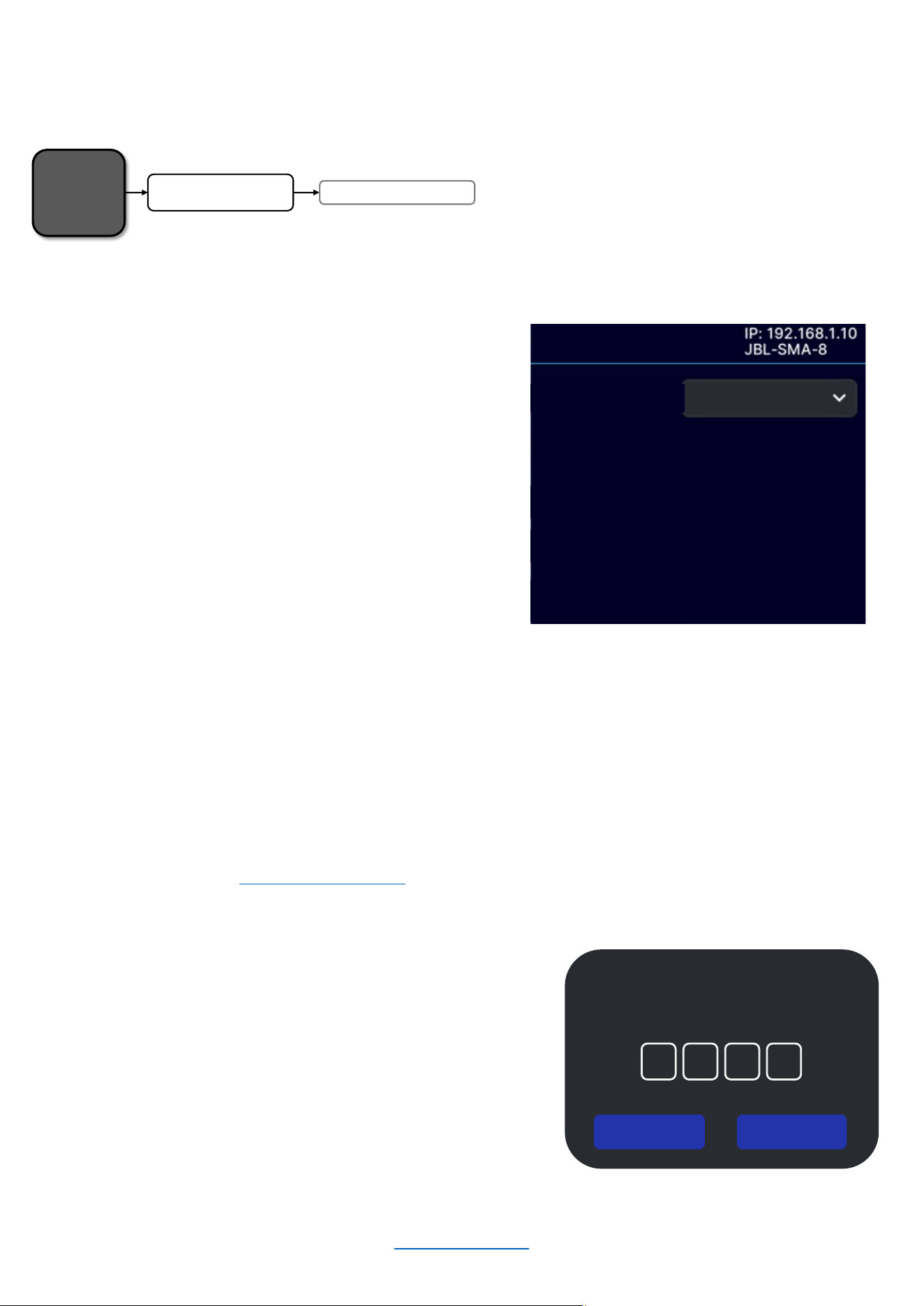
SECURITY / FRONT PANEL LOCKOUT
The front panel can only be locked via the Web UI. If it has been locked, it can be unlocked using the Web UI or by
pressing any button on the front panel of the amplifier and following the unlock procedure as described below:
To Unlock the Amp using the front panel display:
• From the Home screen, press any button
• Using the ENCODER, enter the PIN
• When finished, use the ENCODER to select “UNLOCK”
Always On
ENABLE ON NETWORK INPUTS:
AUTO -STANDBY TIMEOUT (mins)
60
AUTO -STANDBY
THRESHOLD
LIGHTING/DISPLAY OPTIONS
DISPLAY TIMEOUT:
Home
Screen
Lighting/Display Options
System Settings
UNLOCK DEVICE
Enter the PIN to unlock.
0 0 0 0
UNLOC K CANCEL
© 2025 Harman International Table of Contents 30
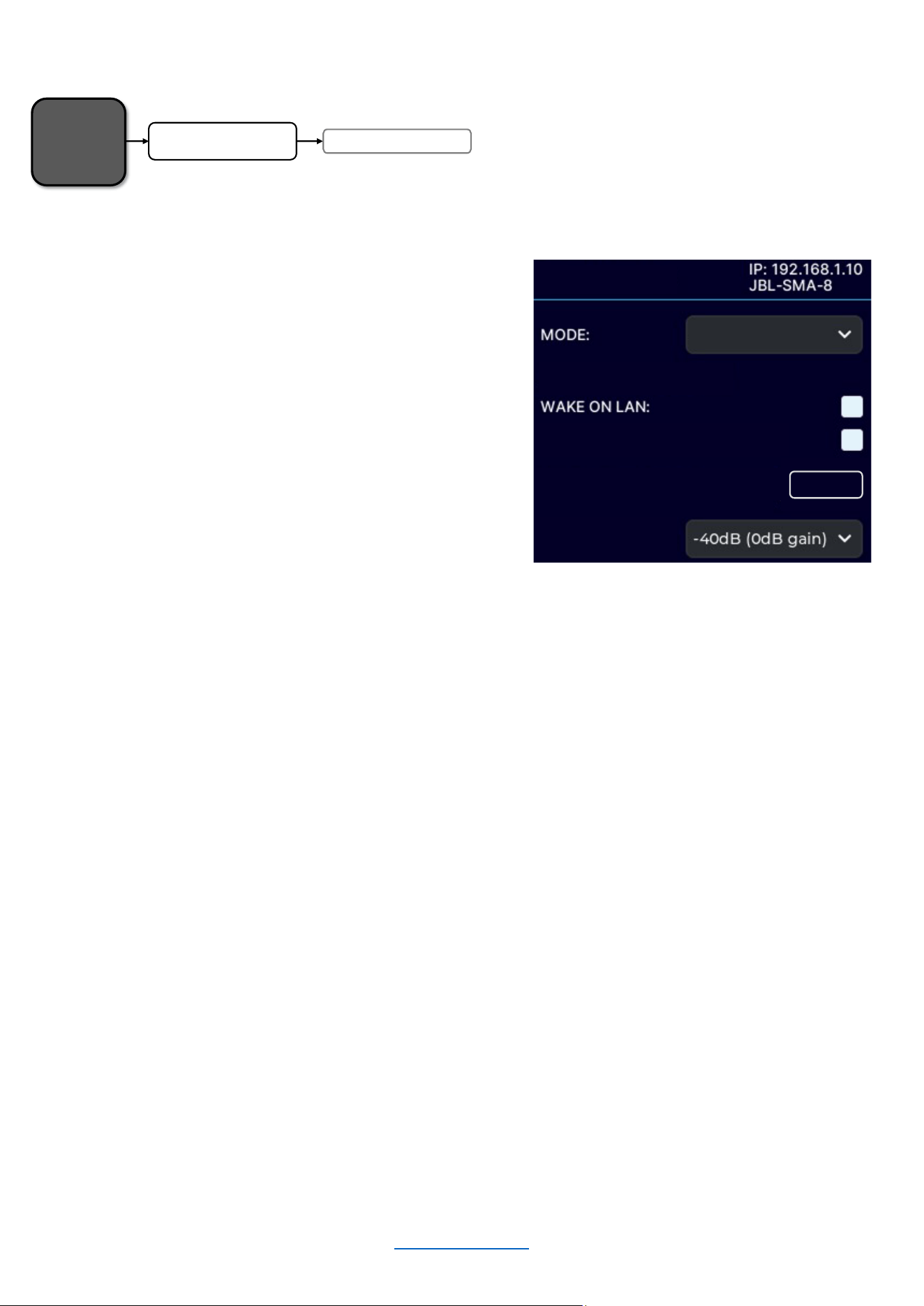
POWER MODES
To Edit Power Mode Settings:
• From the Home screen, press the MENU button
• Select the "System Settings" option from the menu
using the ENCODER
• Select the "Power Modes" option from the menu
• Turn and press the ENCODER to select the desired
settings
• When done, press the BACK button to exit this menu
Available Options:
• SIGNAL SENSE
The SIGNAL SENSE power mode allows the SMA amplifiers to conserve power during periods of inactivity.
The amplifier will automatically enter standby after a period of inactivity. By default, this will occur 60 minutes
after audio is no longer present at the input of the DSP for a given channel. The unit will exit standby when
audio is sensed again at the input of the amplifier.
Available options/parameters:
Wake-on-LAN: Allows amplifier to be turned on from standby by a network message via 3
rd
party controller
(received on the ethernet port)
Enable On Network Inputs: Amplifier will wake upon the presence of a signal on a network input
Auto-Standby Timeout: Determines how many minutes the amp will remain on without a signal
Auto-Standby Threshold: Sets the threshold to determine the signal/no-signal condition
• 12V TRIGGER
The state of the device is controlled solely by the external 12V trigger signal (this mode will be automatically
selected when a 12V trigger signal is present).
NOTE: The front panel standby button will be non-operational in 12V trigger mode. The standby button will
briefly flash blue for 10 seconds when pressed, and the amplifier will power on for a 5-minute window to allow
the power mode to be changed.
• ALWAYS ON
The state of the device is controlled solely by the standby button and WakeOnLan.
Home
Screen
Power ModesSystem Settings
SIGNAL SENSE
ENABLE ON NETWORK INPUTS:
AUTO -STANDBY TIMEOUT (mins)
60
AUTO -STANDBY
THRESHOLD
POWER MODES

© 2025 Harman International Table of Contents 31
DIAGNOSTICS
The Diagnostics screen provides a read-only list of amplifier information.
To Enter the Diagnostics Screen:
• From the Home Screen, press the MENU button
• Select the "System Settings" option from the menu
using the ENCODER
• Select the "Diagnostics" option
• Use the ENCODER to scroll the menu
Figure X: Diagnostics screen
Information Displayed:
• DEVICE NAME
• FIRMWARE VERSION
• SERIAL NUMBER
• MANUFACTURED DATE
Home
Screen
Diagnostics
System Settings
OUTPUT BRIDGING
DIAGNOSTICS
DEV ICE NA ME: JBL-SMA -8
FIRMWA RE: s ma -1234
SERIAL NUMBER
:
IP00004 -LO0000010
MFG DATE: 2024-12-26
© 2025 Harman International Table of Contents 32
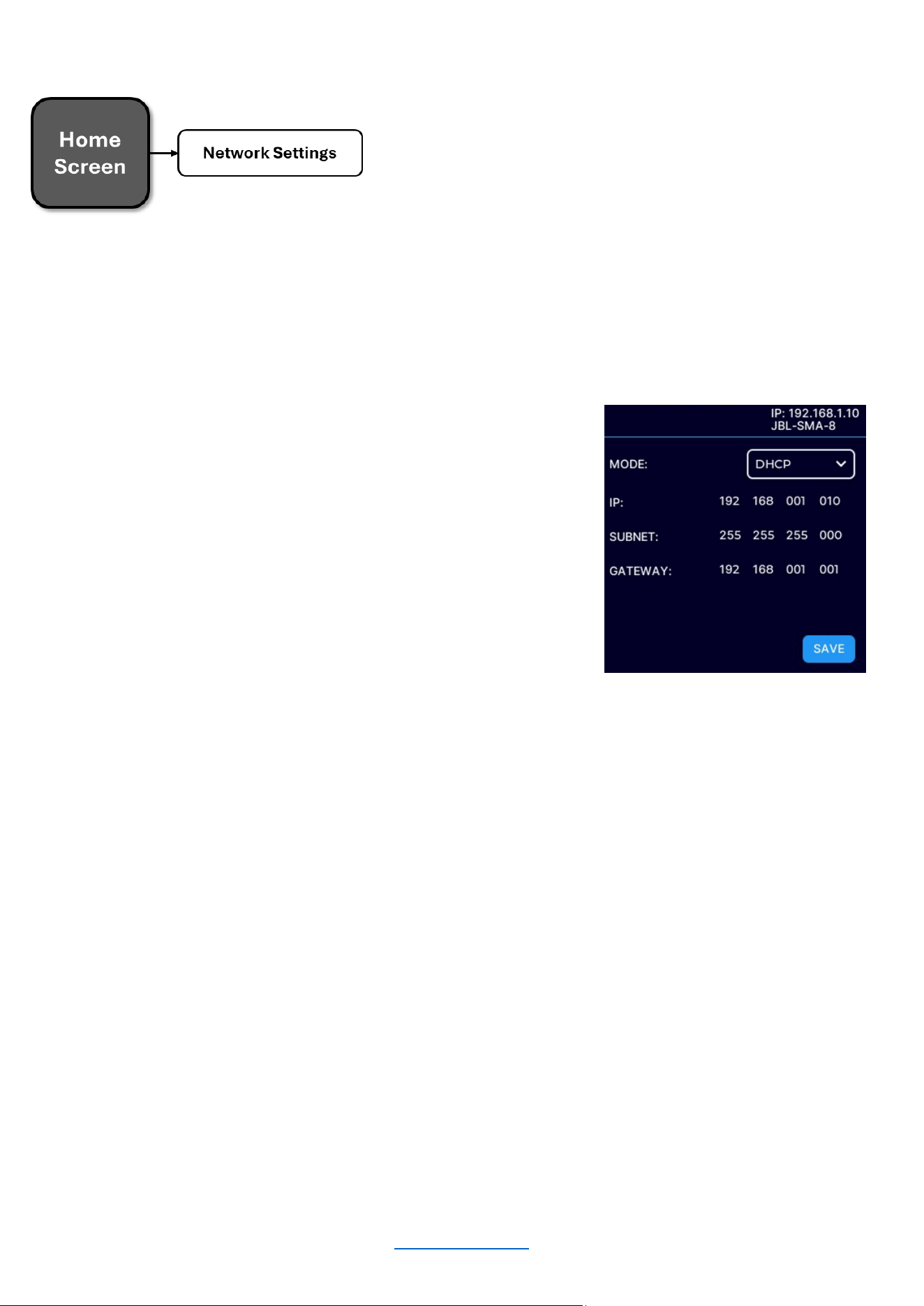
Network Settings
Network settings can be configured from either the front panel display or the Web UI. DHCP is enabled by default,
allowing the SMA amplifier to automatically obtain an IP address when connecting to an Ethernet switch or router
with an active DHCP server, or when using Auto-IP.
To Enter the Network Settings Screen:
• From the Home Screen, press the MENU button
• Select the "Network Settings" option from the menu using
the ENCODER
• Use the ENCODER to select and edit the network settings
• Use the ENCODER to press the SAVE button when
finished editing
Available Parameters:
• MODE
“DHCP” - allows the amplifier to automatically obtain an IP address from a DHCP server or via Auto-IP
“STATIC” – allows manual configuration of the amplifier network settings
• IP ADDRESS
Allows for viewing and editing the IP address of the amplifier
• SUBNET
Allows for viewing and editing the subnet mask of the amplifier
• GATEWAY
Allows for viewing and editing the gateway address of the amplifier if required to access the network. If
using a router, the gateway address will typically be the router address
• MAC ADDRESS (Informational only)
Allows for viewing the MAC Address of the amplifier
MAC ADDRESS
:
NETWORK SETTINGS

© 2025 Harman International Table of Contents 33
Dante / AES67
The Dante / AES67 page if for informational purposes only. It will show the status of the connection/links.
To Enter the Dante / AES67 Screen:
• From the Home Screen, press the MENU button
• Select the "DANTE / AES67" option from the menu using
the ENCODER
• Press the BACK button to exit the menu
Available Parameters
• PRIMARY LINK
Connected/Not Connected
• SECONDARY LINK
Connected/Not Connected
• SYNC
YES / NO
OUTPUT BRIDGING
AES67
PRIMA RY LINK: Not connected
SECONDA RY LINK: Not connected
LOCKED:
Of f
SYNC:
NO
© 2025 Harman International Table of Contents 34
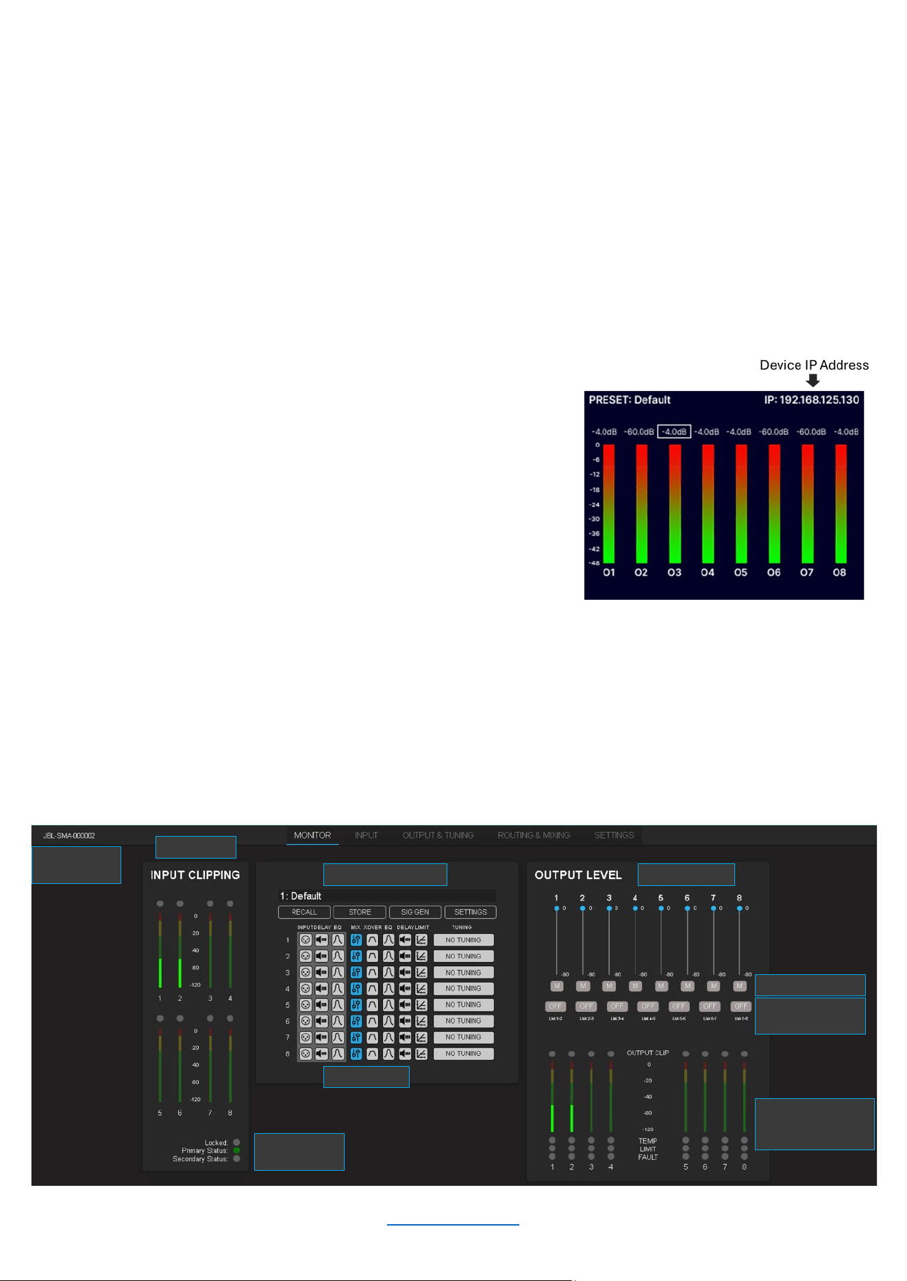
Customizable
Name
Input Meters
Dante/AES67
Status
Store/Recall Presets
DSP Settings
Output Meters /
Limiter / Fault
Status
Output Volume
Mute/Unmute
Link/Unlink
Channels
Configuring The Amp Using the Web Client
This section of the manual describes how to configure the SMA amplifier for your application using the PC web
client. This includes assigning input channels, editing internal routing and DSP settings, and configuring output
settings.
ACCESSING THE WEB CLIENT TO CONFIGURE THE AMPLIFIER OVER A NETWORK
To access the web client, the amplifier must be connected to a TCP\IP network via the rear panel Ethernet port
and, in some cases, configured for the network. Additionally, your PC must be connected to the same network as
the amplifier. When using the same PC to access more than one amplifier through the Web Client, each amplifier
can be individually configured using a single tab. Each tab name will show the name of the corresponding
amplifier. If the graphics appear incorrect, you may need to clear the cache of your web browser.
To Access the Web Client:
1. Open a web browser on your PC
2. Locate the IP address of the unit using the front panel
display as shown to the right
3. Type the IP address of the unit in the browser address
bar and press “Enter”
4. The browser should display the Web interface as shown
below
MONITOR PAGE
The monitor page provides a high-level overview of the amplifier settings and status. This includes input and output
meters, Dante/AES67 Status, presets, DSP block status, output volume levels, muting, channel fader linking, and
limiter and fault status. You can access all of these parameters by clicking on the respective buttons. You can also
store and recall presets from this page.
© 2025 Harman International Table of Contents 35
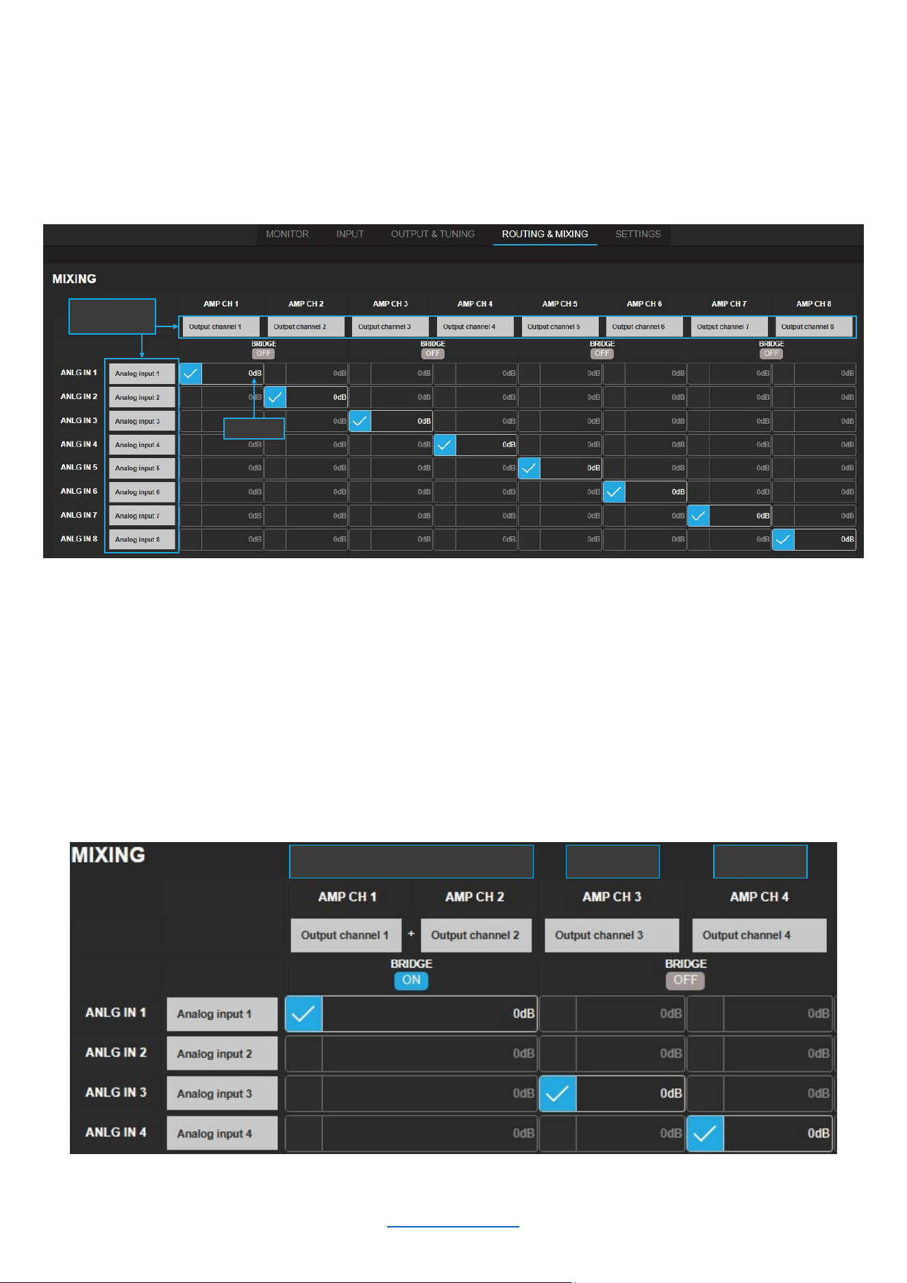
ROUTING AND MIXING
The amplifiers ship with each output channel sourced from its respective analog input (e.g., analog input 1 goes to
output 1, etc.) as shown below. A maximum of 2 input channels can be assigned and consequently mixed to each
output channel by selecting the checkbox next to the intersection of the desired in/out combination.
Channel names are customizable, and levels can be adjusted to create the desired mix.
NOTE: Network (Dante) input channels will only be shown if the device has an active Dante license. To activate
Dante, use the Dante Activator tool from Dante Controller software (v4.5 or later). Once your device is discovered
in the software, you will see your purchase options.
Bridged Mode
As shown below, bridged mode can be engaged by clicking the “ON/OFF” button below the word “BRIDGE”. By
default, all amplifier channels are set to single-ended (SE) operation.
Customizable
Names
Mix Level
Bridged Mode SE Mode SE Mode
© 2025 Harman International Table of Contents 36
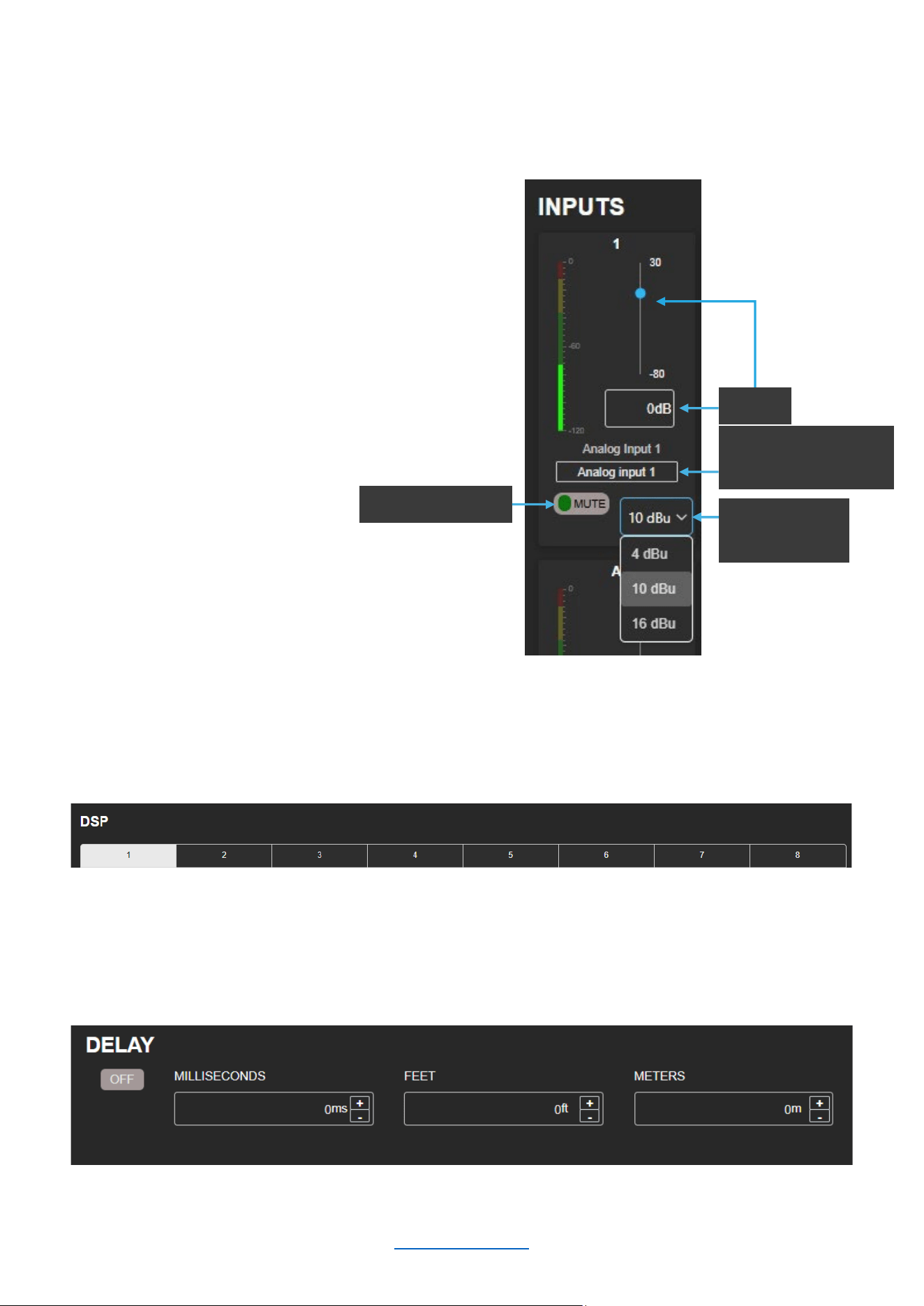
INPUT
The INPUT page is designed to facilitate the configuration of parameters related to input channels, such as input
gain, mute/unmute, input sensitivity, delay, and PEQ.
Input Monitor Section
1. As seen in the figure to the right, the following
parameters can be adjusted here:
a. Input Gain (Range: -80 to +30dB)
b. Channel Name
c. Mute/Unmute
d. Input Sensitivity
2. Network (Dante) input channels will only be
shown if the device has an active Dante license
DSP & Channel Selection
To select which input channel to configure, simply click on the corresponding number in the “DSP” portion of the
INPUT page as shown below (Channel 1 is currently selected).
Delay
Delay can be specified in milliseconds, feet, or meters. When one input field is used to specify the amount of delay,
the other two will update to show the equivalent delay in their corresponding units of measurement.
Mute/Unmute
Customizable
Channel Name
Sensitivity
Select
Gain
© 2025 Harman International Table of Contents 37
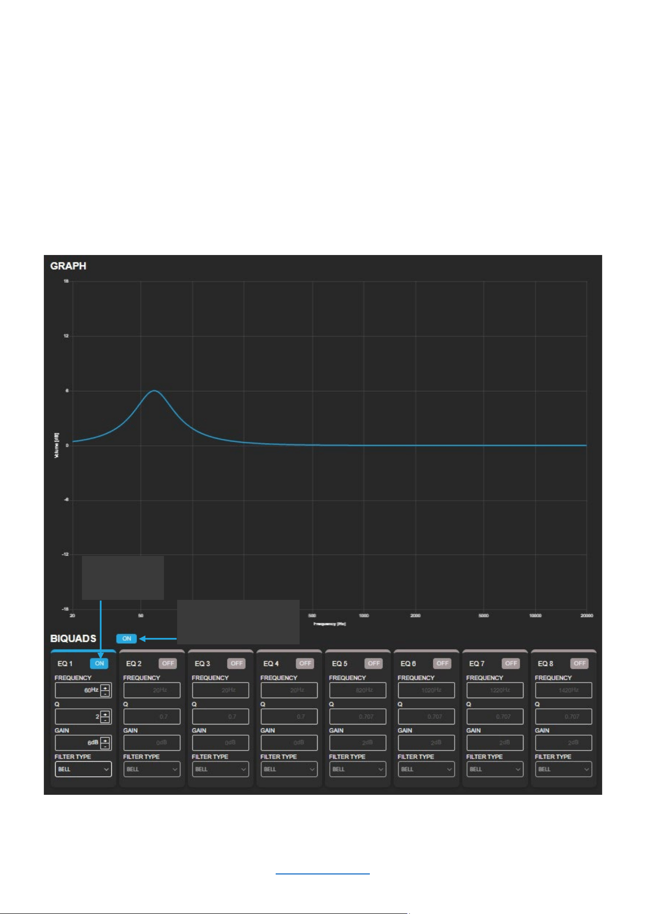
Setting the PEQ
The DSP section includes 8 biquads for each channel that can be configured as the following filter types by using
the “FILTER TYPE” drop-down menu:
BELL
LOW PASS 1ST ORDER
LOW PASS 2ND ORDER
LOW SHELF
HIGH PASS 1ST ORDER
HIGH PASS 2ND ORDER
HIGH SHELF
ALL PASS 1ST ORDER
ALL PASS 2ND ORDER
NOTE: The 1
st
Order Low Pass and High Pass filters have a slope of -6dB/octave. The 2
nd
Order Low Pass and
High Pass filters generally have a slope of -12dB/octave, though that will vary with the Q factor selected. The 1
st
Order All Pass creates a 90-degree phase shift, and 2nd Order All Pass creates a 180-degree phase shift.
In the figure shown below, the first biquad is configured as a “BELL” with 6dB of gain at 60Hz using a Q factor of 2.
The center frequency, Q factor, and gain can all be adjusted via manual entry or by clicking the up/down buttons.
NOTE: The parameters for a specific PEQ band will only be configurable if that PEQ band is ”ON.”
Enable
PEQ Band
Enable/Disable
Channel PEQ
© 2025 Harman International Table of Contents 38
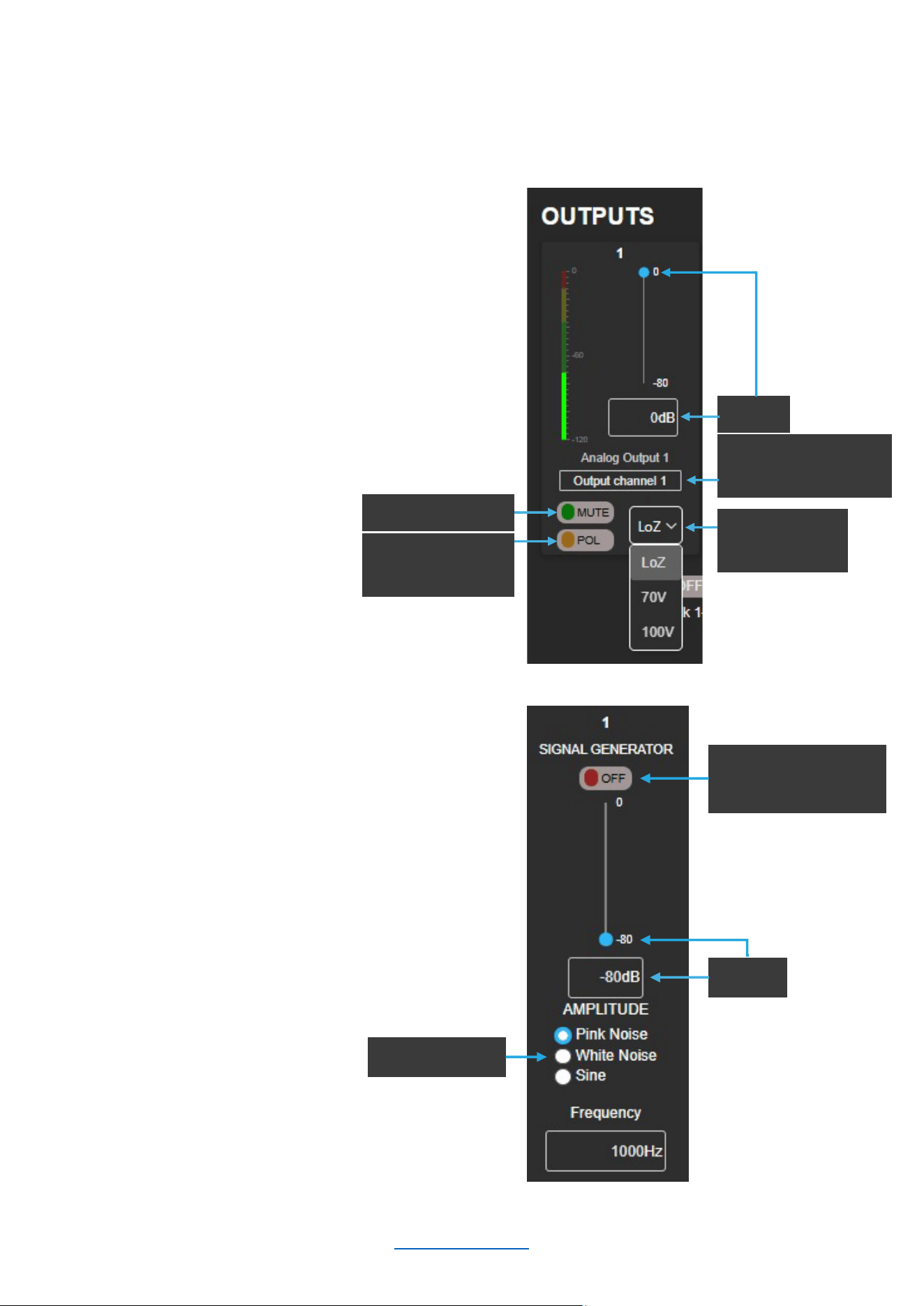
OUTPUT & TUNING
The OUTPUT & TUNING page is designed to facilitate the configuration of parameters related to output channels,
such as gain, mute/unmute, polarity, impedance, delay, crossover, limiter, and PEQ.
Output Monitor Section
1. As seen in the figure to the right, the following
parameters can be adjusted here:
a. Gain (Range: -80 to 0dB)
b. Channel Name
c. Mute/Unmute
d. Polarity
e. Impedance
2. Use “Link On/Off” to link
output faders
NOTE: The SMA-8300 must be
bridged for high impedance 70V/100V operation.
Signal Generator Section
1. As seen in the figure to the right, the following
parameters can be adjusted here:
a. On/Off
b. Gain (Range: -80 to 0dB)
c. Signal Type
i. Pink noise
ii. White Noise
iii. Sine Tone
Polarity
Normal/Invert
Mute
/Unmute
Impedance
Select
Customizable
Channel Name
Gain
Signal Type
Signal Gen
Enable/Disable
Gain
© 2025 Harman International Table of Contents 39
DSP
To select which input channel to configure, simply click on the corresponding number in the “DSP” portion of the
OUTPUT & TUNING page as shown below (Channel 1 is currently selected).
Setting the PEQ
The output PEQ also contains 8 biquads for use on each output channel. The instructions for configuring the
output PEQ are identical to those of the input PEQ. Click here to navigate to the PEQ configuration instructions.
Crossover
Available options for the crossover include Butterworth 12 – 24 – 36dB/octave and Linkwitz-Riley 12 – 24 –
36dB/octave. These can be selected as shown below, along with the corner frequency, gain (-80 to +24dB), and
Enable/Disable.
HP and LP Enable/Disable
Filter Type
Selection
© 2025 Harman International Table of Contents 40
LevelMAX™ (Limiter)
Limiters are used to set a "ceiling" on the output level to protect drivers from over-excursion. The thermal limiters in
the amplifiers can also protect against thermal driver failure (overheating). For advanced users, LevelMAX can be
configured manually. If you are not already familiar with how to configure the parameters in the figure below, it is
NOT recommended that you configure LevelMAX manually.
Speaker Tunings
Speaker tunings apply DSP settings to a particular output channel, making it easy to optimize a speaker's
performance.
Selecting a Speaker Tuning
1. As seen in the figure to the right, you can select
between different speaker tunings by selecting:
a. Brand
b. Market
c. Series
d. Model
e. Usage
2. Regarding Usage: For active bi-amp
configurations with the JBL Synthesis SCL-1,
please refer to the SCL-1 owner’s manual
© 2025 Harman International Table of Contents 41
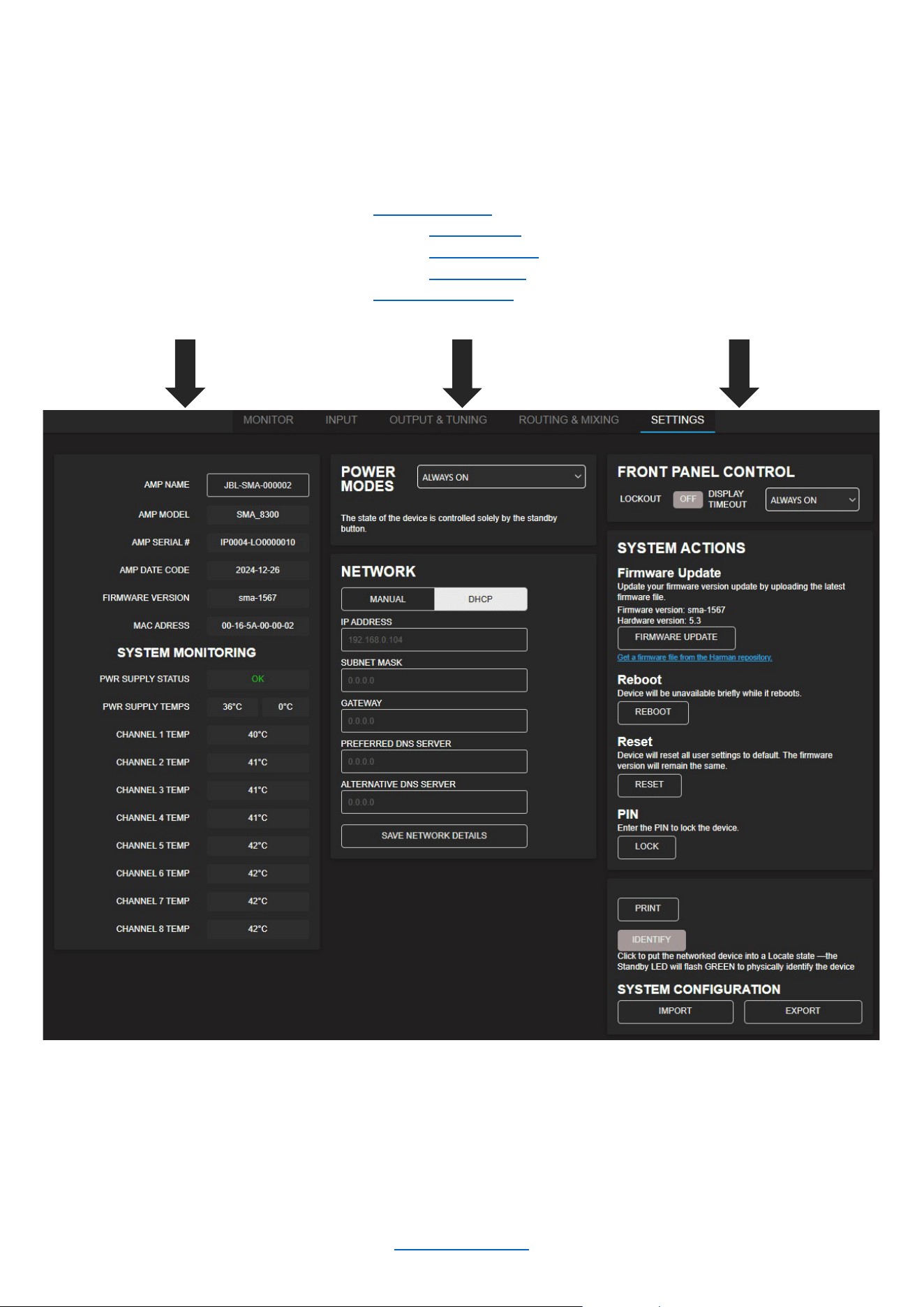
SETTINGS
The SETTINGS page is used to obtain information about your unit, configure system-level settings, and manage
network and software details. The following items can be found on this page:
• Amp ID information
• Customizable Amp Name
(50 characters or less, no
special characters)
• System Monitoring such as
temperature and power
supply status
• Power modes:
o Always ON
o Signal Sense
o 12V Trigger
• Network Settings
• Front Panel Display Settings
• System Updates
• Reboot, Reset, and PIN
setting (recommended)
• Unit Identification Feature
• Import/Export Configuration
NOTE: Depending on the situation, it may be appropriate to set a PIN code to lock the amplifier(s). It is highly
recommended in situations where someone other than the responsible installer/technician may accidentally
change the settings.
© 2025 Harman International Table of Contents 42
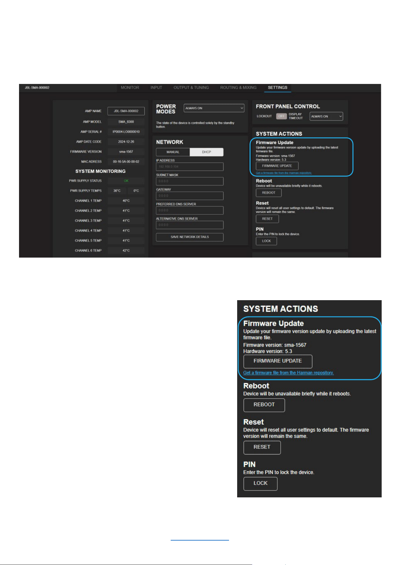
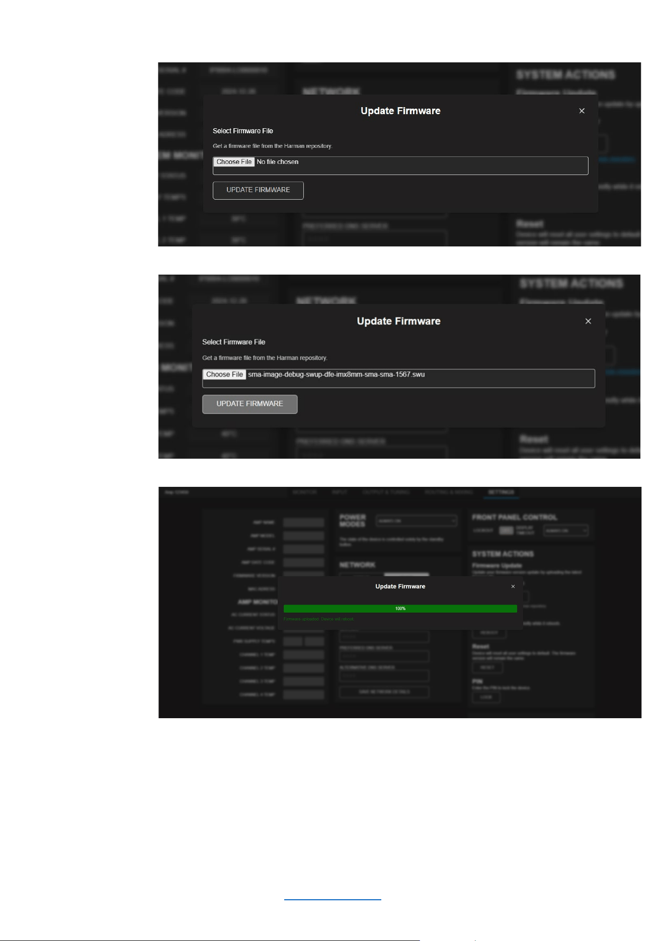
Firmware Update Process
Occasionally, a new version of firmware will become available. When this is the case, it is strongly recommended
that you perform the update for your amplifier. You can perform the update via the “SETTINGS” page of the Web
UI under “SYSTEM ACTIONS” as shown below.
To update the firmware for your amplifier:
1. Click “Get a firmware file from the Harman repository”
2. Download the latest firmware update zip file to your
computer
3. Unzip the compressed folder
4. Click the “FIRMWARE UPDATE” button
5. Click “Choose File”
6. Select the firmware file from the unzipped folder (the
extension will be “.swu”)
7. Click “UPDATE FIRMWARE” to begin the update
process
8. The front panel display of the amplifier will show the
firmware update progress bar move from 0% to 100%
over a period of a few minutes
9. Allow the amplifier to automatically reboot
10. Once the process is completed, connect to the web
client to verify that the firmware version has been
updated
© 2025 Harman International Table of Contents 43
Firmware Update Process (continued)
Click to choose a FW
update file
Click “UPDATE
FIRWMARE” to begin
the update
The Update Progress
Bar shows that the
FW update has been
sent to the amplifier
Finally, the front panel display of the amplifier will show the actual firmware update process. The amplifier must be
allowed to automatically reboot so that the firmware update can be completed.
NOTE: It is good practice to clear the browser cache after a successful firmware update.
© 2025 Harman International Table of Contents 44
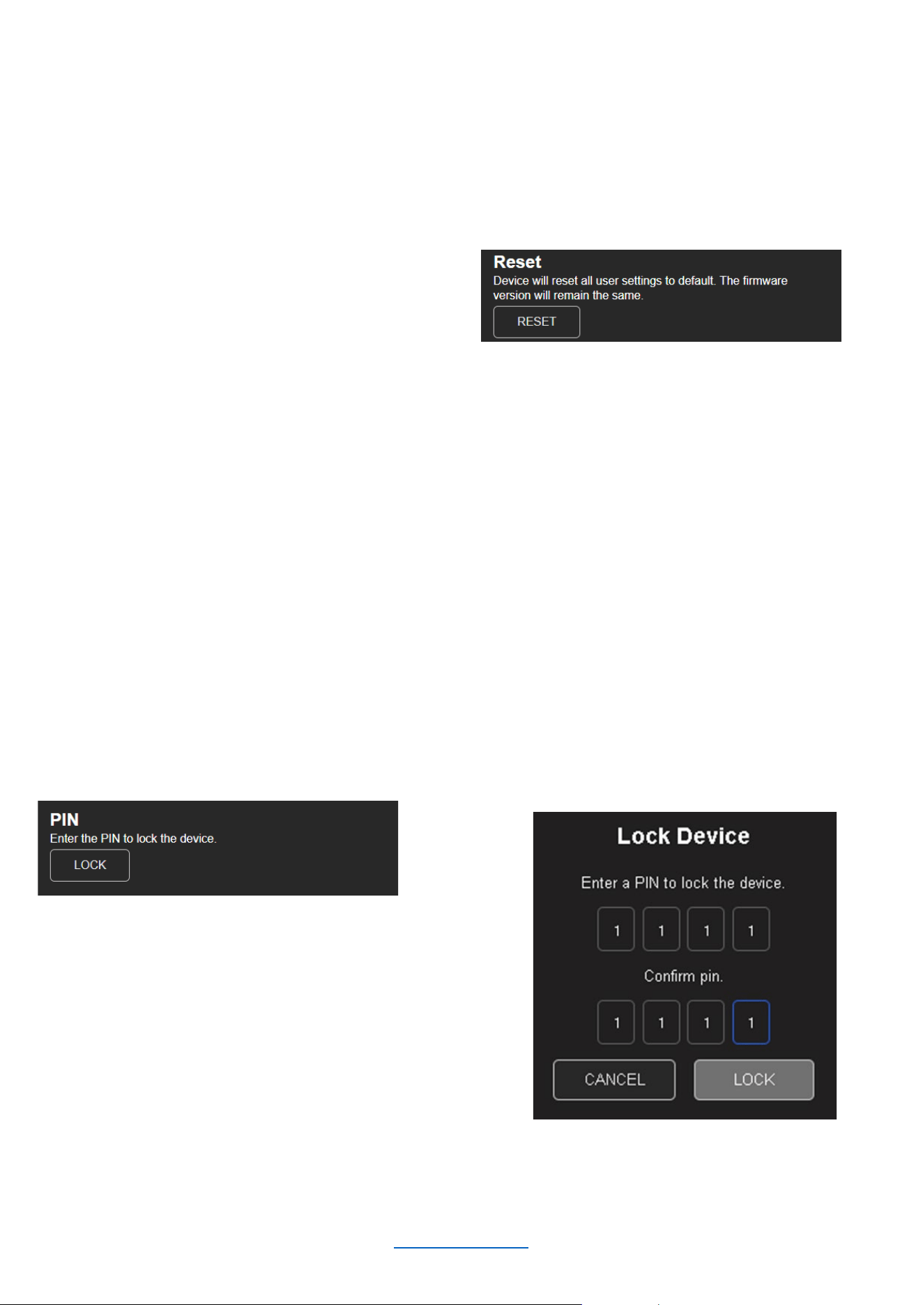
Reset
The Reset function allows an SMA amplifier to be reverted to its default settings. When initiated, it will perform the
following tasks:
• Erase all user presets (this includes all user DSP and configuration settings)
• Reset all system settings
To RESET the amplifier:
1. Click the “RESET” button
2. Confirm that you wish to perform a reset
Locking And Unlocking the Amplifier Using a PIN
The amplifiers can be locked and unlocked via the Web UI using a PIN. When an amp is locked, the settings
cannot be changed without first unlocking it. Setting a PIN and locking the amplifier is highly recommended in
situations where someone other than the responsible installer/technician may accidentally change the settings.
IMPORTANT NOTE: Make sure to store your PIN safely. In order to reset the PIN, press and hold the BACK
button in the front panel until the display shows the volume monitoring view.
To LOCK the amplifier using the PIN:
1. Click the “LOCK” button
2. Choose and enter a PIN twice
and click “LOCK” to lock the
device
© 2025 Harman International Table of Contents 45
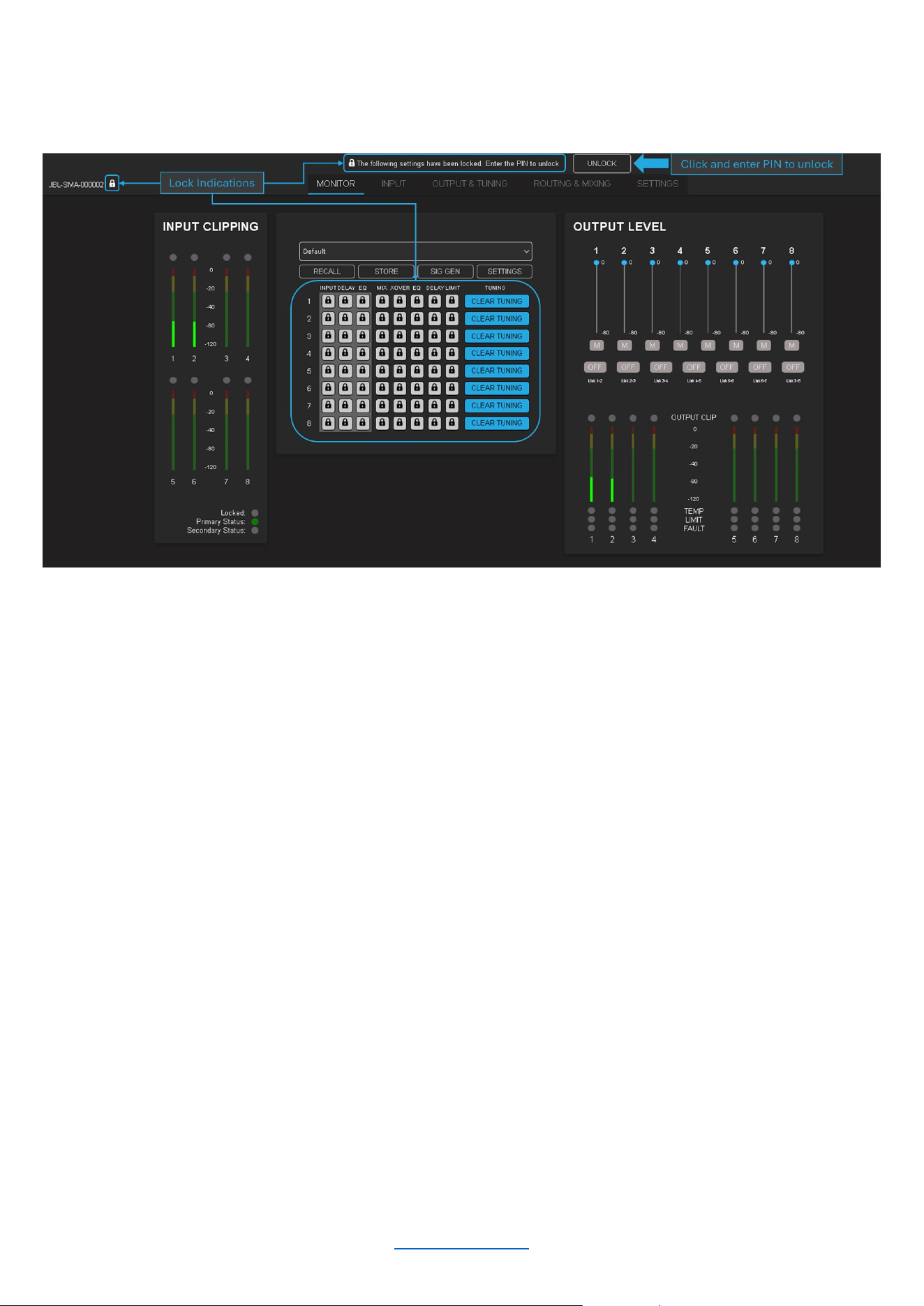
When the amplifier is locked, there are several areas on the monitor page that will indicate such (as seen in the
image below).
To UNLOCK the amplifier using a PIN:
1. Click the “UNLOCK” button
2. Enter the PIN and click “UNLOCK” to unlock the amplifier
© 2025 Harman International Table of Contents 46
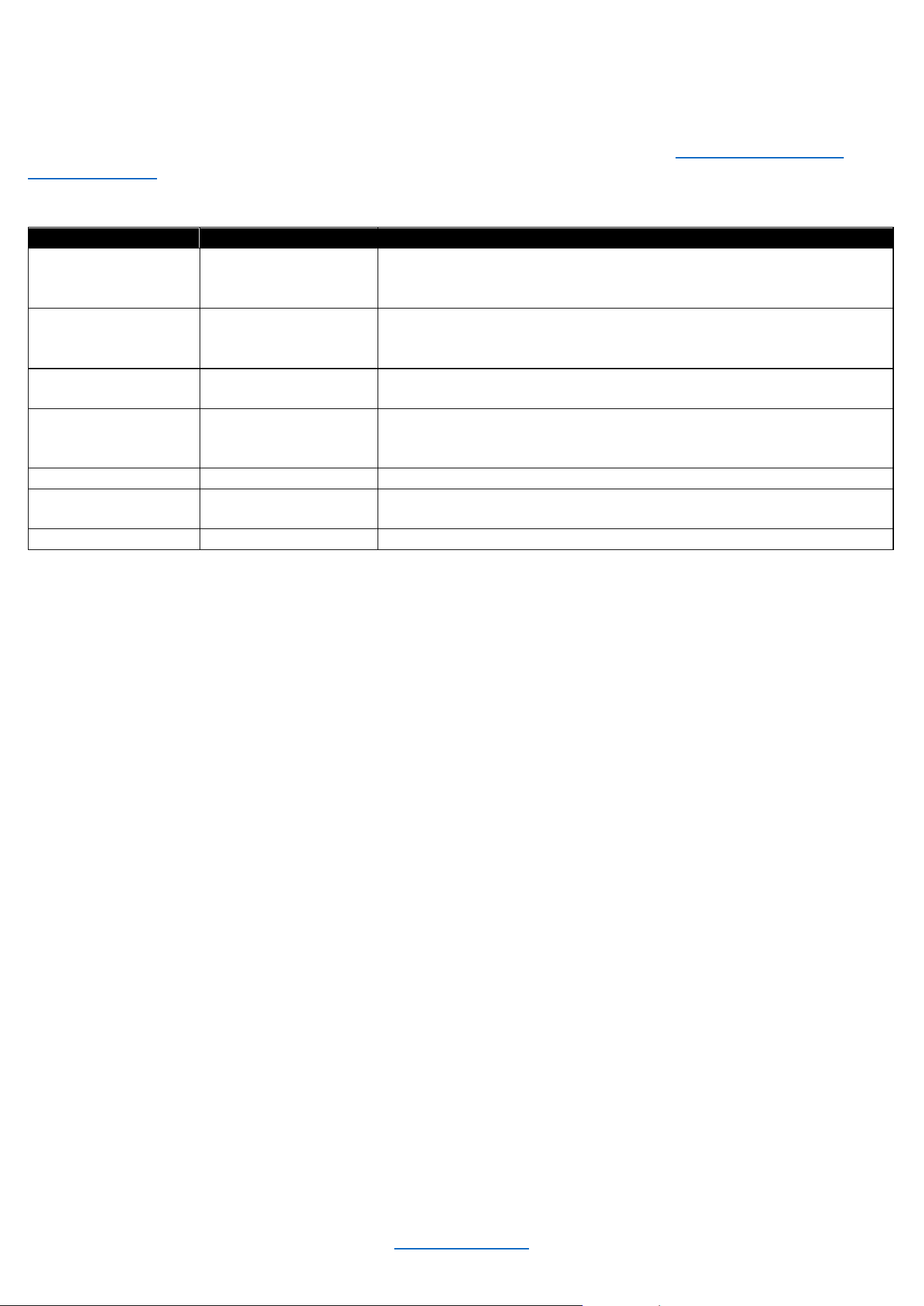
System Protection
FAULTS
The amplifier will enter a fault state if it senses an unsafe condition. This protection is for both internal and external
faults. Be sure that the load connected to the amplifier is within the 2.7-16 Ohms limit (5.4-16 Ohms in Bridge
Mono mode). If wiring and load are verified as correct and the fault condition persists, contact JBL Synthesis
technical support. If for any reason a loss of power occurs, the amp will return to its most recent state upon reboot.
Fault
Display Message
Description
High Voltage
“Over Voltage
Protection”
The power supply's high voltage rails are no longer
within a safe operating range for the amplifier or other
components attached
Low Voltage
“Under Voltage
Protection”
The power supply's high voltage rails are no longer
within a safe operating range for the amplifier or other
components attached
OCP
“Over Current
protection”
At the amplifier output, either a low resistance load is detected or
a short circuit is detected
Thermal
“Over Temperature
Protection”
An amp channel and/or the power supply has
exceeded the maximum acceptable temperature
threshold
DCerror
“DC Error”
DC Voltage has been detected at the output of the amplifier
Power Manager
Fault
“PMU Fault”
Power Manager Fault
Power Supply Fault
“PSU Fault”
Power Supply Fault
THERMAL LIMIT
If the amplifier power supply and/or any channels become too hot for safe operation, a thermal fault will occur. If a
channel's temperature reaches 80° Celsius, a message will appear in the front panel display to indicate the onset
of audio compression. The amplifier will continue to run in this state until either the temperature is reduced to a
safe operating range, or if the temperature continues to rise, the channel will shut off to protect itself above 100°
Celsius. The amplifier will exit the thermal fault state only when the temperature drops back below the thermal limit.
AC UNDER/OVER-VOLTAGE PROTECTION
If the AC line voltage drops below the acceptable operating voltage of the amplifier, the amplifier’s power supply
will turn off and the Power LED will flash red. The amplifier will power on when the AC line voltage returns to safe
operating levels.
FAN-COOLED CHASSIS
SMA series amplifiers are cooled by quiet, variable-speed fans. Maximum fan noise level of the SMA amplifier is
51dBA. The fans will pull air from side-to-side. The following fault conditions cause the fan to turn on full speed
• High frequency fault (excessive high frequency signal content has been sensed at the output of the amplifier)
• Thermal fault (excessive power supply or channel temperature is detected)
NOTE: The fan adjusts itself according to the temperature and will automatically ramp up and down based on it.
UNIVERSAL SWITCHING POWER SUPPLY
The SMA Series amplifiers incorporate a switching power supply designed for high efficiency and high output
power. They accept AC supply voltages from ~100V to ~240V.

© 2025 Harman International Table of Contents 47
Troubleshooting
Power indicator and LCD are off
• Confirm the amplifier is plugged in to power
• Confirm AC power is supplied to the amplifier
• Ensure rear panel power switch is in the “ON” position
Power indicator is continuously flashing red
• The AC line voltage has dropped below 50V at the power supply. See "System Protection" for information on
AC under/over voltage protection
Pressing the standby button does not immediately wake the amplifier. Power indicator flashes blue briefly
• The amplifier is asleep via the 12V trigger
• Confirm that the 12V trigger signal is present
• If needed, press the standby button to allow for a 5 minute window to change the power mode. See “Power
Modes” section
Over temperature protection fault is indicated in the display
• The amplifier is becoming too hot for safe operation; allow the amplifier to cool
• Check for loads less than 2.7Ω (SE Operation) or 5.4Ω (Bridge Mono Operation)
• Check for excessive input levels
• Check for proper ventilation. See the "Proper Cooling" section for information on rack mounting and cooling
• See the "System Protection" section for detailed information on thermal limits
Some other fault is indicated in the display
• There are a number of conditions that result in a fault error being displayed: the operating temperature
exceeds 100°C, or an output short circuit is detected. See the "System Protection" section for more
information on these protection features
Distorted sound
• Load is wired incorrectly, or Dual/Bridge mode is configured incorrectly — both should be verified. See the
"Wiring Output Connectors" section and "Output Setup" section for more information
• Input is overloaded by a signal level that is too high. Turn down the amplifier input level controls, or turn down
the output of the source signal until the channel input meter is no longer at clip
• If the signal sounds distorted even though the channel input meter does not indicate clipping, the signal may
be distorted before it reaches the amplifier input. Check the gain staging and the output levels of the upstream
components
No sound, despite Power LED being blue and level meters indicating presence of an input signal
• Speaker not connected. Power off the amplifier, disconnect the AC power cord, then verify speaker
connection
• Short circuit due to speaker failure. From the front panel display, determine which channel has the short.
Power down the amplifier then disconnect the AC power cable. Remove the shorted load from the channel
(and possibly attached cables) and have it checked by a qualified technician. Reconnect the power cord and
power up the amplifier. If the shorted condition remains after the load is removed, contact JBL Synthesis
technical support
Input meters do not indicate presence of input signal, and audio is being sent to the amplifier's input
• Input signal level is very low. Double check the gain structure of the system and ensure that the amplifier's
input levels are set accordingly
• Input routing is not configured correctly for application. See "Input Setup”
If all else fails…
• Contact an authorized JBL Synthesis dealer
• Contact JBL Synthesis technical support

© 2025 Harman International Table of Contents 48
Specifications
SMA-8300
Connectors
Analog audio input
8x XLR (Balanced)
Digital audio input (Dante/AES67)
2x RJ45
Speaker output
8x Binding Posts, accommodates 10AWG
wire, spade and banana termination
12VDC trigger control
1x 3.5mm (in)
1x 3.5mm (out)
Network/monitoring/control
1x RJ45
Power
Standard IEC
Power (2 channels driven, 0.5% THD max)
Rated Power (8Ω)
300W
Rated Power (4Ω)
600W
Rated Power (8Ω Bridged, one zone driven)
1,200W
Performance
Digital signal processing
96kHz, 32-bit floating point
Frequency response (4Ω, 20Hz – 20kHz)
±0.1dB
Total harmonic distortion
(at full rated power, from 20Hz – 20kHz)
0.02%
Analog input signal to noise ratio (ref. Rated power, ‘a’-wtd.)
>112dB
Analog input signal to noise ratio (ref. Rated power, 20Hz –
20kHz)
>99dB
Damping factor (20Hz to 100Hz)
>1000
Input impedance (nominally balanced, nominally unbalanced)
70 kΩ balanced, 35 kΩ unbalanced
Maximum input level (low amp gain mode)
+21dBU
Load impedance stereo/dual mode
2.7Ω –16Ω load
Impedance bridge mono
5.4Ω – 16Ω
Maximum fan noise (REF. dB SPL @ 1M)
51dBA
Electrical
Power supply
100–240V, 50/60Hz
Physical
Dimensions incl. rack ears, connectors, controls
(H x W x D)
3.5 x 19.0 x 17.0 in
(88.9 x 482.6 x 432.6 mm)
Dimensions excl. rack ears, connectors, controls
(H x W x D)
3.5 x 17.0 x 15.7 in
(88.9 x 431.8 x 400.0 mm)
Net Weight
23.1 lb (10.5 kg)
Recommended operating ambient temperature range
0° to 45°C
Recommended storage temperature range
-30° to 70°C

© 2025 Harman International Table of Contents 49
SMA-4750
Connectors
Analog audio input
4x XLR (Balanced)
Digital audio input (Dante/AES67)
2x RJ45
Speaker output
4x Binding Posts, accommodates 10AWG
wire, spade, and banana termination
12VDC trigger control
1x 3.5mm (in)
1x 3.5mm (out)
Network/Monitoring/Control
1x RJ45
Power
Standard IEC
Power (2 channels driven, 0.5% THD max)
Rated Power (8Ω)
750W
Rated Power (4Ω)
1,500W
Rated Power (8Ω Bridged, one zone driven)
2,500W
Performance
Digital signal processing
96kHz, 32-bit floating point
Frequency response (4Ω, 20Hz – 20kHz)
±0.5dB
Total harmonic distortion
(at full rated power, from 20Hz – 20kHz)
0.02%
Analog input signal to noise ratio (ref. Rated power, ‘a’-wtd.)
>114dB
Analog input signal to noise ratio (ref. Rated power, 20Hz –
20kHz)
>99dB
Damping factor (20Hz to 100Hz)
>1000
Input impedance (nominally balanced, nominally unbalanced)
70 kΩ balanced, 35 kΩ unbalanced
Maximum input level (low amp gain mode)
+21dBU
Load impedance stereo/dual mode
2.7Ω –16Ω load
Impedance bridge mono
5.4Ω – 16Ω
Maximum fan noise (REF. dB SPL @ 1M)
51dBA
Electrical
Power supply
100–240V, 50/60Hz
Physical
Dimensions incl. rack ears, connectors, controls
(H x W x D)
3.5 x 19.0 x 17.0 in
(88.9 x 482.6 x 432.6 mm)
Dimensions excl. rack ears, connectors, controls
(H x W x D)
3.5 x 17.0 x 15.7 in
(88.9 x 431.8 x 400.0 mm)
Net Weight
21.8 lb (9.9 kg)
Recommended operating ambient temperature range
0° to 45°C
Recommended storage temperature range
-30° to 70°C
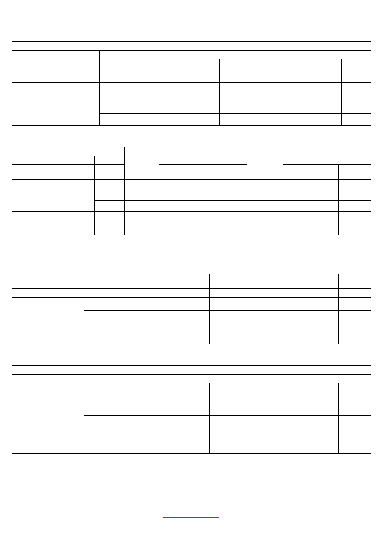
© 2025 Harman International Table of Contents 50
POWER DRAW AND THERMAL
JBL Synthesis SMA-8300 Single Ended Mode
120V AC/60Hz
230V AC/50Hz
Condition
Load
Line
current
(amps)
Power Dissipated as Heat
Line current
(amps)
Power Dissipated as Heat
watts
BTU
kcal/hr
watts
BTU
kcal/hr
At Idle Awake
N/A
0.634
66.3
226
57.0
0.434
65.4
223
56.3
1/8 Power Pink Noise Typical
of program material just at clip
4 ohms
6.69
187
638
161
3.46
166
566
143
8 ohms
3.52
104
355
89.5
1.83
95.7
326
82.3
1/4 Power Pink Noise Typical
of program material at
extreme clip
4 ohms
12.9
327
1115
281
6.51
264
900
227
8 ohms
6.43
156
532
134
3.32
134
457
115
JBL Synthesis SMA-8300 Bridge Mono
120V AC/60Hz
230V AC/50Hz
Condition
Load
Line
current
(amps)
Power Dissipated as Heat
Line
current
(amps)
Power Dissipated as Heat
watts
BTU
kcal/hr
watts
BTU
kcal/hr
At Idle Awake
N/A
0.634
66.3
226
57.0
0.434
65.4
223
56.3
1/8 Power Pink Noise
Typical of program material
just at clip
4 ohms
14.4
400
1364
344
7.14
300
1023
258
8 ohms
6.84 202 689 174 3.52 180 614 155
1/4 Power Pink Noise
Typical of program material
at extreme clip
8 ohms 13.0 337 1149 290 6.57 274 934 236
JBL Synthesis SMA-4750 Single Ended Mode
120V AC/60Hz
230V AC/50Hz
Condition
Load
Line
current
(amps)
Power Dissipated as Heat
Line
current
(amps)
Power Dissipated as Heat
watts
BTU
kcal/hr
watts
BTU
kcal/hr
At Idle Awake
N/A
0.55
54.8
187
47.2
0.41
54.5
186
46.9
1/8 Power Pink Noise
Typical of program
material just at clip
4 ohms
7.93
184
627
158
4.08
156
532
134
8 ohms
4.12
100
314
86.0
2.14
92
314
79.2
1/4 Power Pink Noise
Typical of program
material at extreme clip
4 ohms
16.7
381
1299
328
8.81
260
887
224
8 ohms
7.71
159
542
137
3.97
132
450
115
JBL Synthesis SMA-4750 Bridge Mono
120V AC/60Hz
230V AC/50Hz
Condition
Load
Line
current
(amps)
Power Dissipated as Heat
Line
current
(amps)
Power Dissipated as Heat
watts
BTU
kcal/hr
watts
BTU
kcal/hr
At Idle Awake
N/A
0.55
54.8
187
47.2
0.41
54.5
186
46.9
1/8 Power Pink Noise
Typical of program
material just at clip
4 ohms
16.6
426
1453
367
8.04
315
1074
271
8 ohms 8.03 190 648 163 4.12 160 546 138
1/3 Power Pink Noise
Typical of program
material at extreme clip
8 ohms 16.3 370 1262 318 7.84 270 921 232
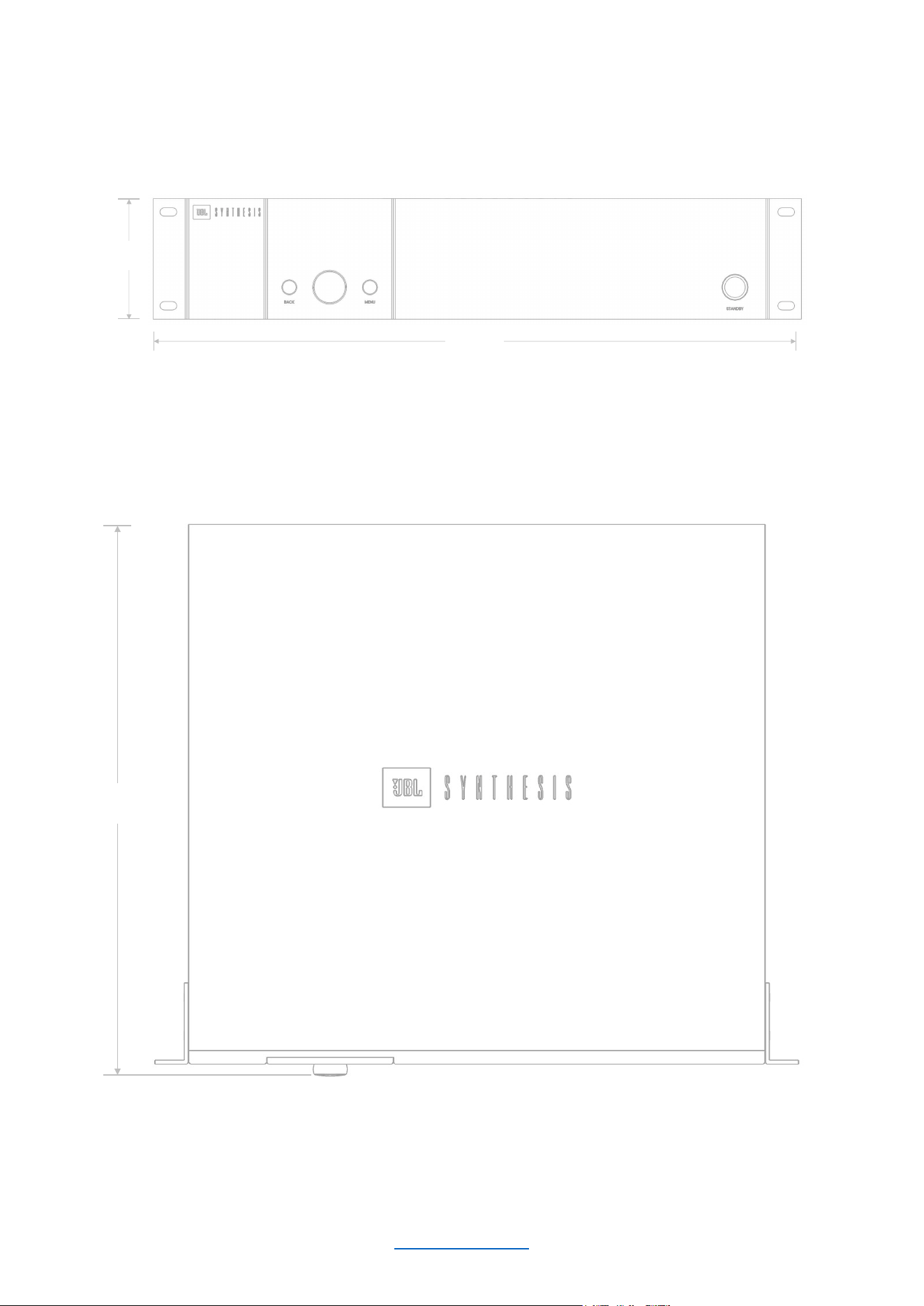

Harman International Industries, Incorporated.
8500 Balboa Blvd, Northridge CA 91329 United States.
European Representative: Harman International Industries, Incorporated.
EMEA Liaison Office, Danzigerkade 16G, 1013 AP Amsterdam, The Netherlands.
UK Business Address:
Ground Floor, Westside 2, London Road, Apsley, Hemel Hempstead, Hertfordshire, HP3 9TD, United Kingdom.
© 202
5 Harman International Industries, Incorporated. All Rights Reserved.
JBL is a trademark of Harman International Industries, Incorporated
registered in the United States and other countries.
Features, Specifications, and Appearance subject to change without notice.