
Technical Support and E-Warranty Certificate
www.vevor.com/support
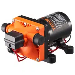
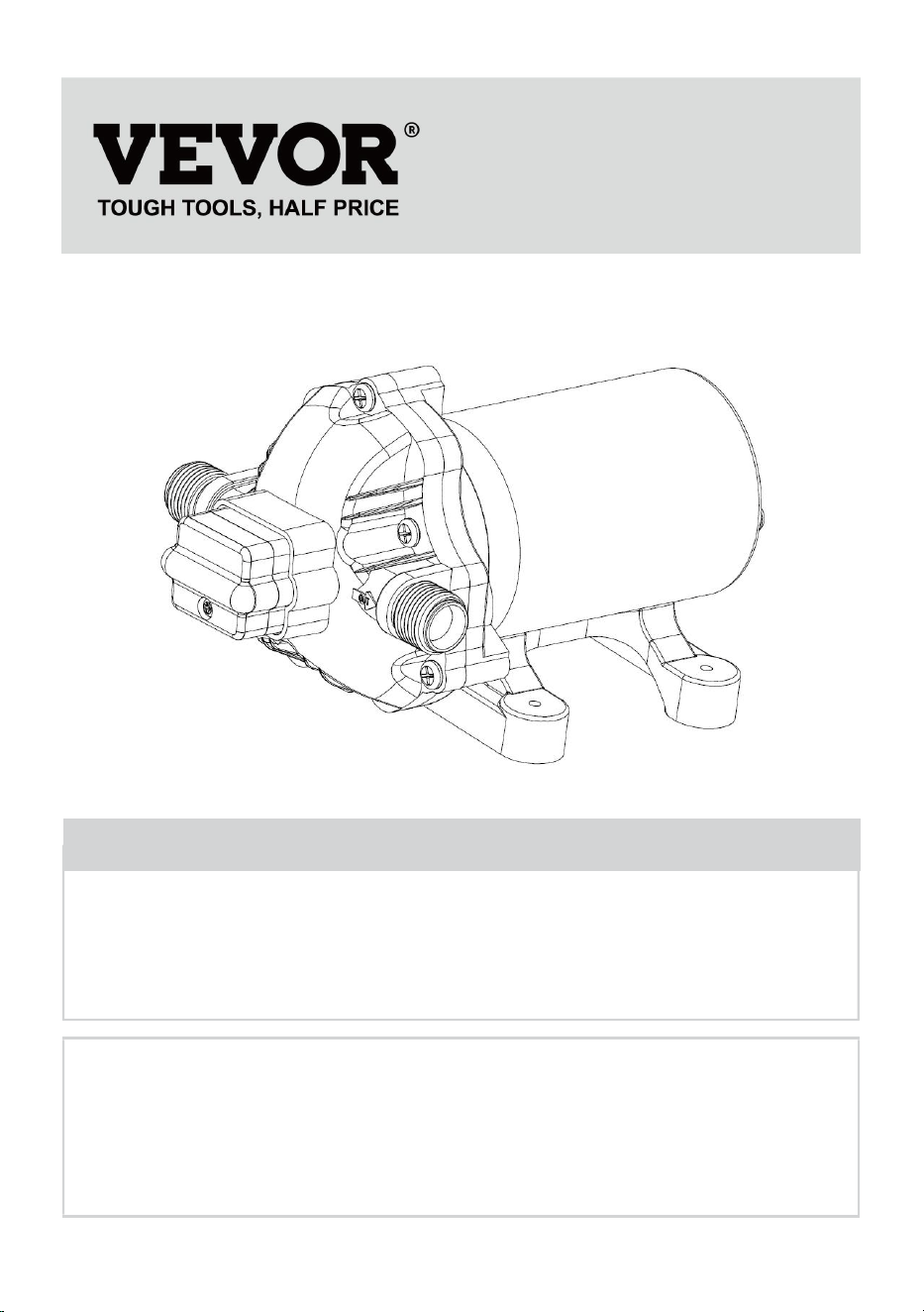
12 VOLT POTABLE WATER PUMP
MODEL: NMDP33-G18-60-12 /
NMDP33-G30-50-12 / NMDP33-G35-50-12
We continue to be committed to provide you tools with competitive price.
"Save Half", "Half Price" or any other similar expressions used by us only represents an
estimate of savings you might benefit from buying certain tools with us compared to the major
top brands and does not necessarily mean to cover all categories of tools offered by us. You
are kindly reminded to verify carefully when you are placing an order with us if you are
actually saving half in comparison with the top major brands.
- 1 -
MODEL: NMDP33-G18-60-12/NMDP33-G30-50-12/NMDP33-G35-50-12
Have product questions? Need technical support? Please feel free to
contact us:
Technical Support and E-Warranty Certificate
www.vevor.com/support
NEED HELP? CONTACT US!
This is the original instruction, please read all manual instructions
carefully before operating. VEVOR reserves a clear interpretation of our
user manual. The appearance of the product shall be subject to the
product you received. Please forgive us that we won't inform you again if
there are any technology or software updates on our product.
12 VOLT POTABLE
WATER PUMP
- 2 -
Warning-To reduce the risk of injury, user must read instructions
manual carefully.
CORRECT DISPOSAL
This product is subject to the provision of European Directive
2012/19/EU. The symbol showing a wheelie bin crossed through
indicates that the product requires separate refuse collection in the
European Union. This applies to the product and all accessories
marked with this symbol. Products marked as such may not be
discarded with normal domestic waste, but must be taken to
acollection point for recycling electrical and electronic devices.
An economical workhorse, the 33 Series is engineered for flexibility.The
3-chamber series is our Heavy-Duty water pump. It provides high-volume
water flow with reduced pump cycling, thanks to the large three-chamber
diaphragm. With on-demand switch. The 33 Series is available in three sizes,
1.8GPM/60psi, 3.0GPM/50psi, and 3.5GPM/50psi, meet your special
requirements with positive predictable performance. The 33 Series can reduce
rapid cycling and allow water to flow back from the outlet side to the inlet side
of the pump. We also offer a variety of easy-connect fittings and filters.
PRODUCT SPECICATIONS
Property
Specifications
NMDP33-
G18-60-12
NMDP33-
G30-50-12
NMDP33-
G35-50-12
Rated Voltage
DC12V
DC12V
DC12V
Rated Pressure
60 PSI
50 PSI
50 PSI
Number of Chamber
3 PCS
3 PCS
3 PCS
Max. Flow
1.8 GPM
3.0 GPM
3.5 GPM
Inlet/Outlet Diameter
1/2" MNPT
1/2" MNPT
1/2" MNPT

- 3 -
An incredible feature list, high-quality components, plus amazing performance.
The three-chamber high-volume design, driven by a heavy-duty motor
produces flow rates of 1.8GPM/3.0GPM/3.5 GPM, capable of self-priming up
to 6 vertical feet, and can run dry, making it the price-to-performance leader.
This pump also offers a variety of easy-connect fittings and filters.
FEATURES
·3 -chamber diaphragm pump
·Continuous duty
·Industrial-standard mounting pattern
·Run dry capable for normal workloads
·Automatic: controlled by pressure switch
·Self priming
·Quiet Operation
·Ignition protected
APPLICATIONS
·Yacht/RV/caravan pressurized water system
·Sprayer fixtures (vehicle-mounted sprayers, electric sprayers)
·Cleaning machines Humidifiers water purification, medical apparatus
·Food beverage filling & liquid transfer
·Solar water system
·Any other pressurization system
INSTALLATION
Materials
1.diaphragm pump with related accessories
2.(at least) pieces of flexible, reinforced hose piping, with collapsing strength of
twice the inlet collapsing pressure(hose must be minimum 1/2"D)
3.stainless steel hose clamps and screws

- 4 -
4.screws to fasten the pump to the mounting surface
1 electrical cut off switch
1 fuse
1 screwdriver
1 strong cutting implement for tubing (if desired)Teflon tape or sealant
Setup
1. The pump may be mounted in any position. If mounted vertically, the pump
head should be in the down position to avoid leakage into the motor casing in
the event of a malfunction.
2. Secure the feet, but do not compress them. Over tightening the securing
screws may reduce their ability to dissipate noise and vibration.
3.The inlet and outlet hoses must be 1/2" (13 mm) ID reinforced hoses. The
diameter of branch and individual supply lines from the outlet should be no
smaller than 3/8"(10 mm).
4. Plumb the system using high pressure (2 x pump rating), braided, flexible
tubing to minimize vibration/noise.
5.Do not apply inlet pressure in excess of 30psi. In general, try to avoid any
inlet pressure completely.
6.Avoid any kinks or fittings which could cause excessive restrictions.
7.Strainer should be attached to the inlet side.
8.The fittings must be secured to avoid leakage
9.Use clamps at both ends of the hose to prevent air leaks into the water line.
10. If a check valve is installed in the plumbing, it must have a cracking
pressure of no more than 2 psi.
11. If applying a sealer or plumbing tape, be careful not to over tighten, as they
may be sucked into.
12. This pump should be wired on its own dedicated circuit. Connect the
positive lead (red) to the positive terminal of your battery and the negative
wire(black) to the negative terminal of your battery.
13. In an easily accessible location, install a switch to control electricity to the
pump. Turn the pump off when not used for extended periods or when the tank
is empty.
14.The electrical circuit should be protected with an over-current protection

- 5 -
device(fuse) in the positive lead. This pump requires a 15 amp fuse.
15. The pump circuit should not include any other electrical loads.
16. As the water supply pump is non-essential, reference the wire Chart under
the electrical information. Be sure to have the correct wire sizing for the length
of wire you are using.
17.After installation, check the voltage at the pump motor. Voltage should be
checked when the pump is operating. Full voltage must be available at the
pump motor at times.
Notes
1. Flexible potable water hose or PEX tubing is recommended instead of rigid
piping at the pump. If you choose to use rigid piping, provide a short length of
hose between the pipe and the pump to avoid noise and vibration.
2. We do not recommend the use of metal fittings. When possible, use the
provided plastic fittings.
3. Do not adjust the bypass personally without the help of a technician.
4. Lack of sanitizing and maintenance is one of the main reasons for the
underperformance of the pump. Please do maintenance and winterize the
pump at appropriate times, especially before and after a period of storage.
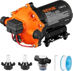
ACCESSORIES
Item
Quantity
NMDP33-
G18-60-12
NMDP33-
G30-50-12
NMDP33-
G35-50-12
Manual
1
1
1
Hose Adapter
x
2
2
Filter
x
1
1
Hexagon Bolt
x
1
1
Sealing Tape
x
1
1
- 6 -
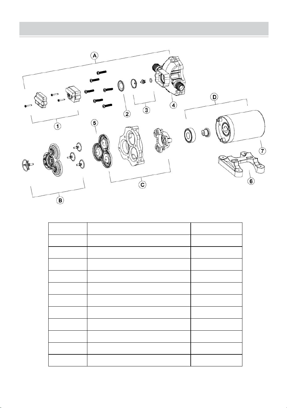
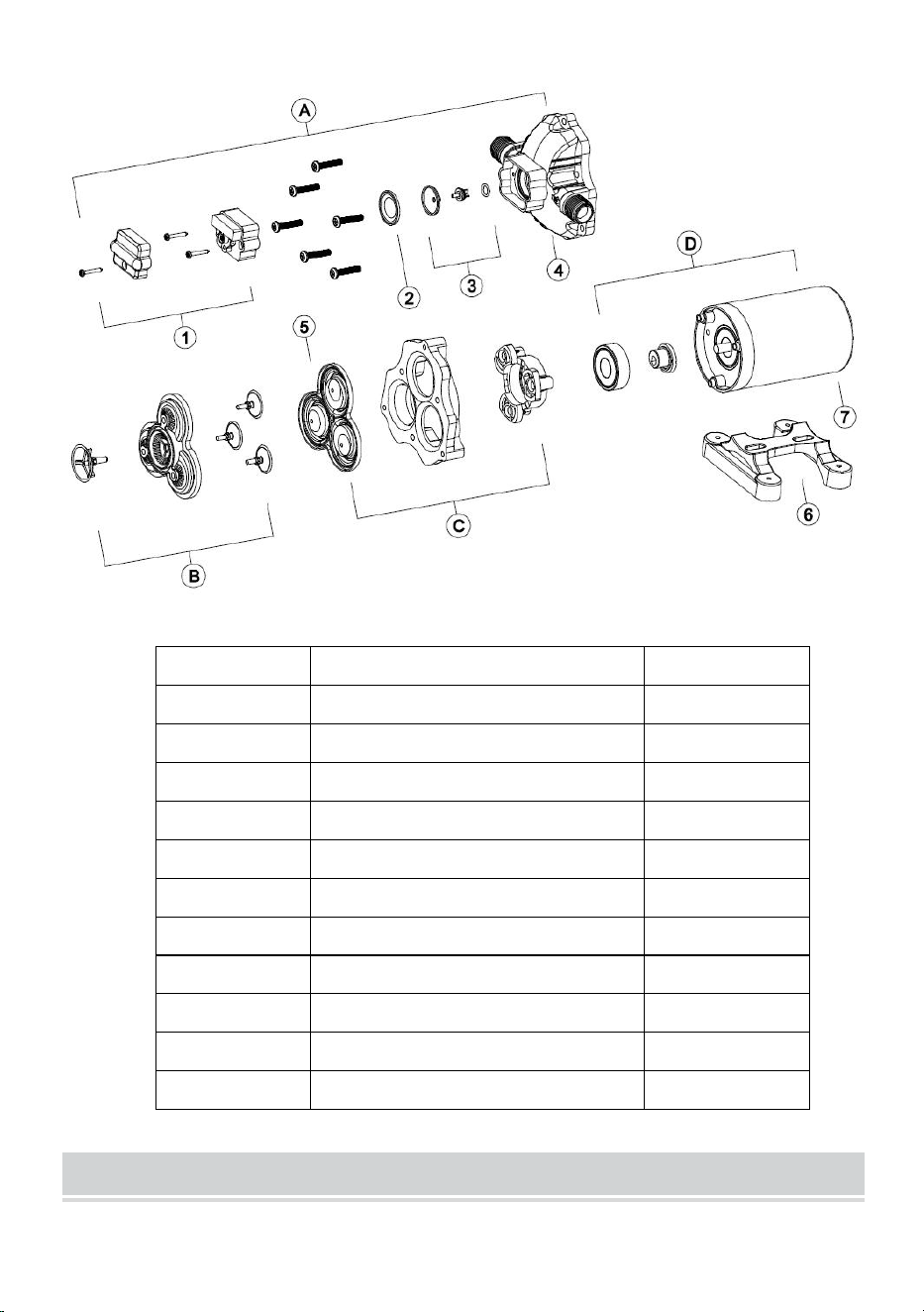
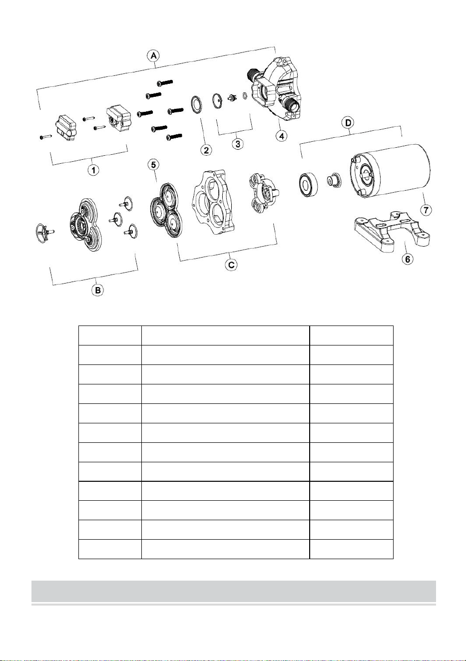
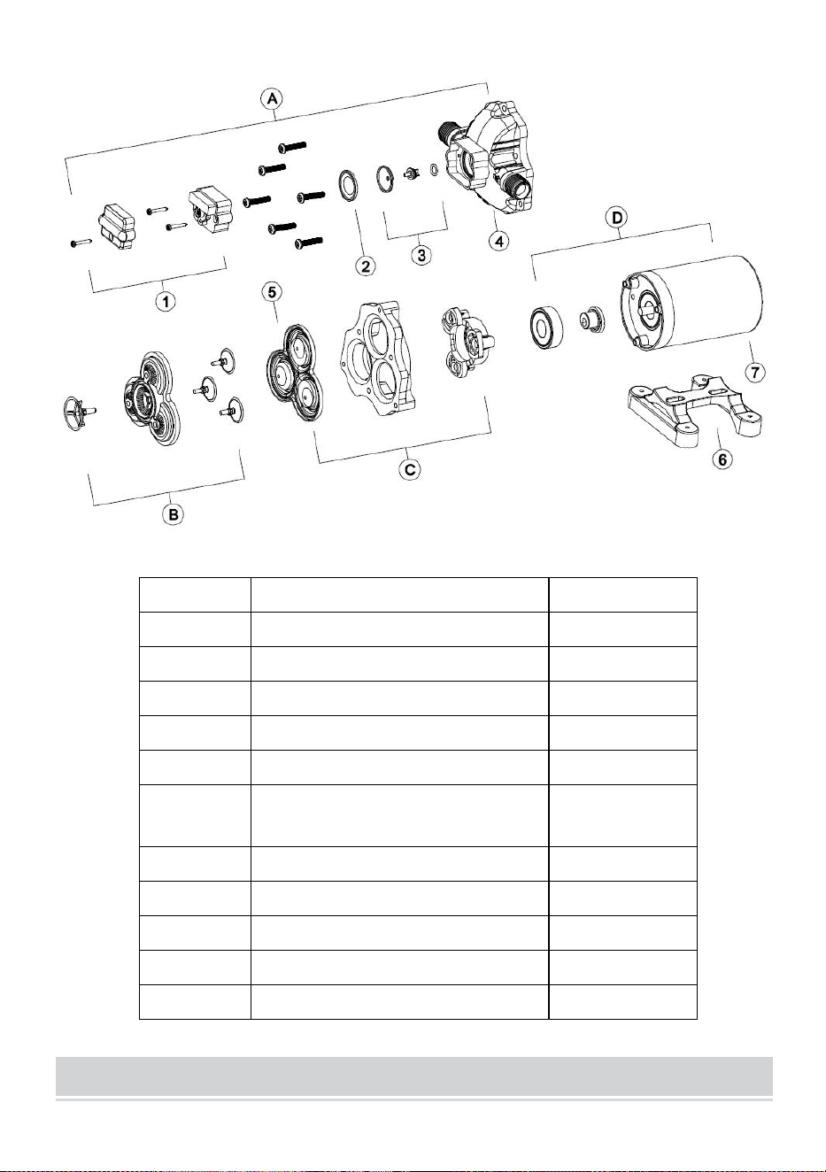
EXPLODED VIEWS
KEY
Description
Quantity
A
Pump Head Assembly
1
B
Valve Assembly
1
C
Diaphragm Assembly
1
D
Motor Assembly
1
1
Pressure Switch
1
2
Diaphragm of Pressure Switch
1
3
Valve Core
1
4
Pump Head
1
5
Diaphragm
1
6
Rubber Foot
1
7
Motor
1
- 7 -
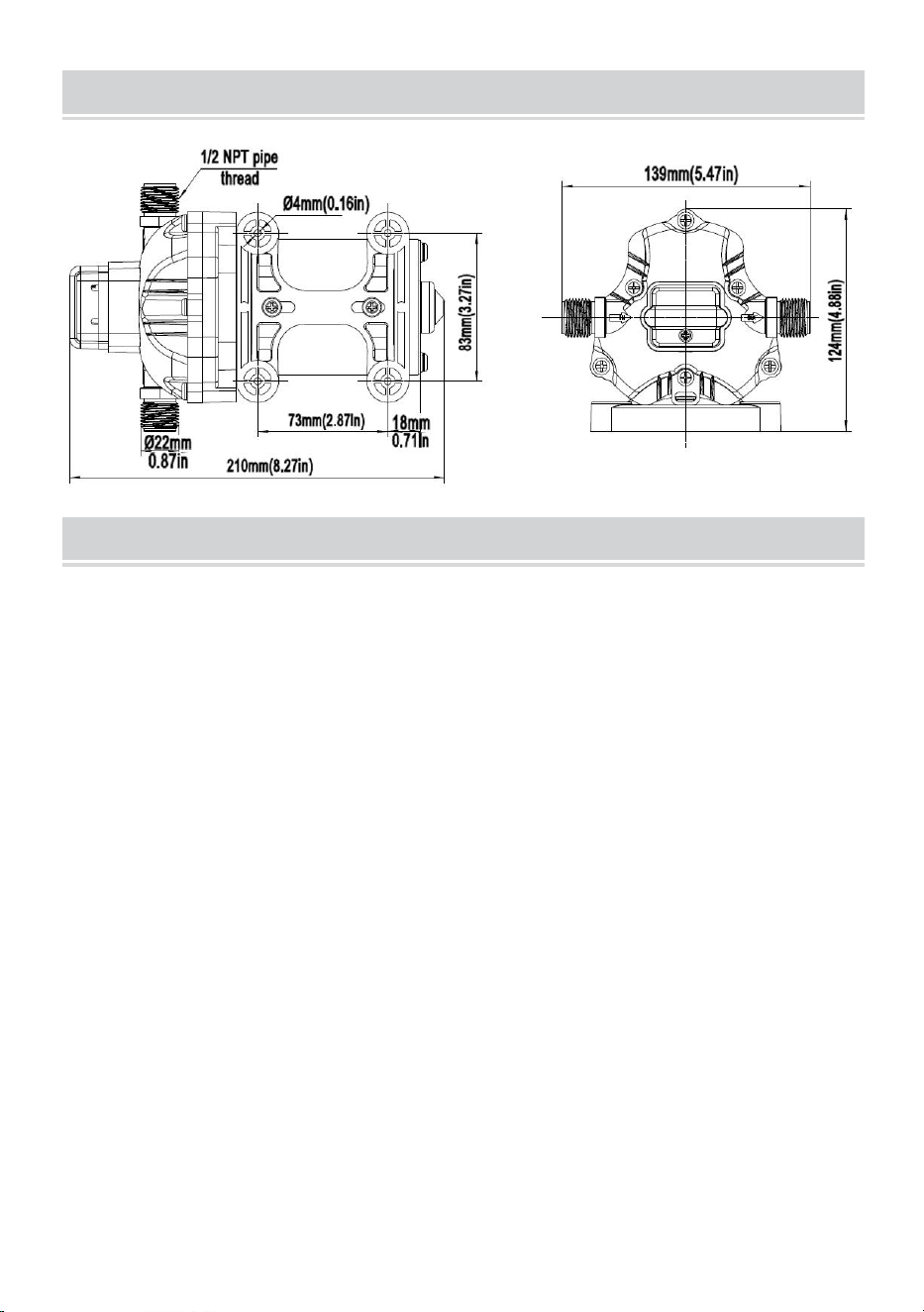
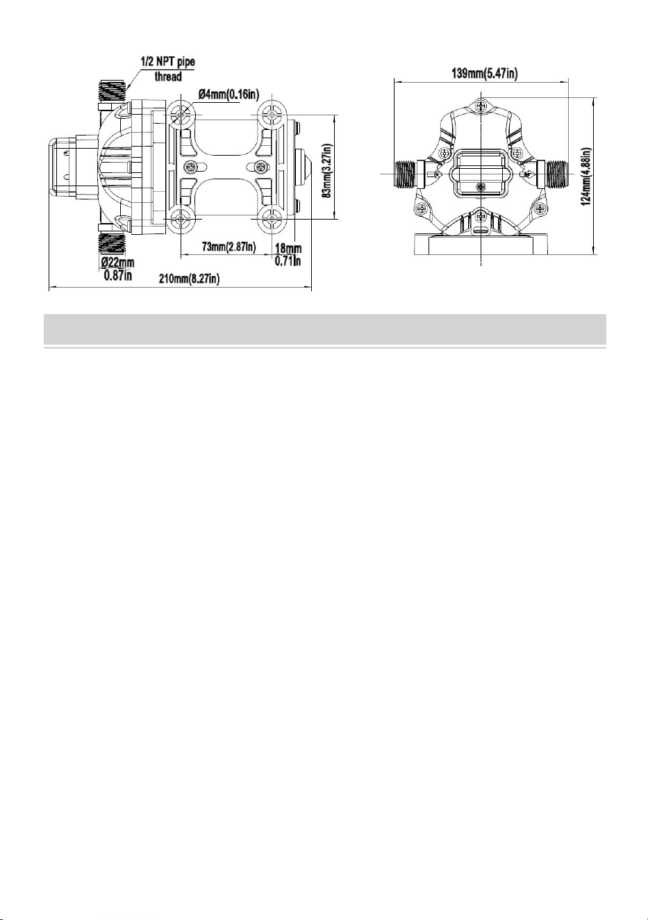
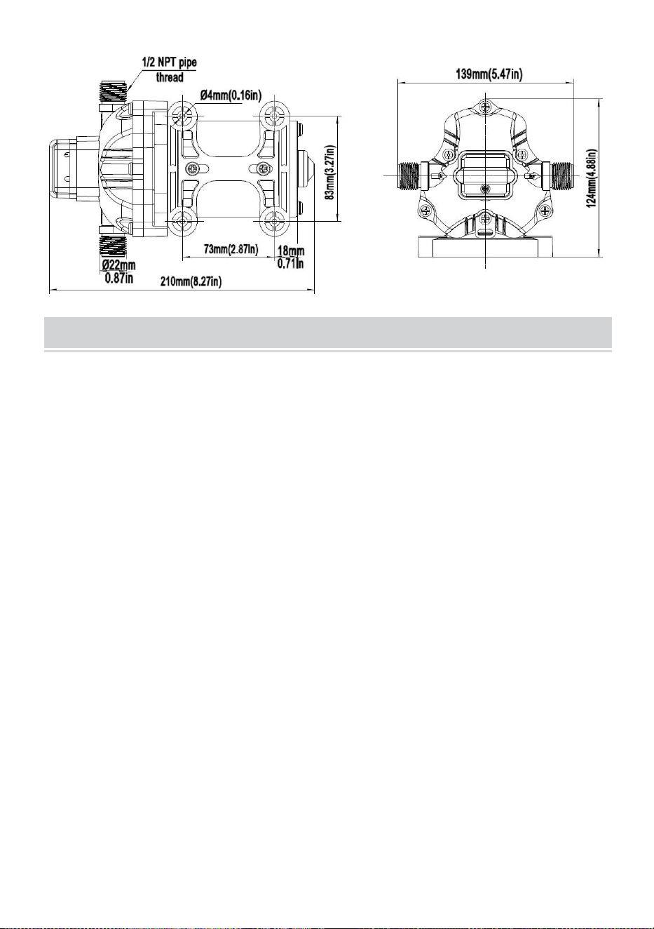
PRODUCT SIZE
TROUBLESHOOTING
PULSATING FLOW- PUMP CYCLES ON AND OFF
·Check lines for kinks.
·Plumbing lines or fittings may be too small.
·Clean faucets and filters.
·Check fitting tightness for air leaks.
FAILURE TO PRIME BUT MOTOR OPERATES-NO PUMP
DISCHARGE
·Restricted intake or discharge line.
·Air leak in intake line.
·Punctured pump diaphragm
·The initial amp supply is not enough to sufficiently start the motor.
·Debris clogs in the valves.
·Crack in the pump housing.
MOTOR FAILS TO TURN ON
· Loose or improper wiring.
· The pump circuit has no power.
· Blown fuse.
· Failed pressure switch.
· Defective motor.
- 8 -
PUMP FAILS TO TURN OFF AFTER ALL FIXTURES ARE CLOSED
· Punctured diaphragm.
· Discharge line leak.
· Defective pressure switch.
· Insufficient voltage.
· Clogged valves in the pump head.
LOW FLOW AND PRESSURE
· Air leak at the pump intake.
· Accumulation of debris inside pump or plumbing.
· Worn pump bearing (possibly accompanied by loud noise).
· Punctured diaphragm.
· Defective motor.
NOISY
·Check if the mounting feet are compressed too tightly.
·Is the mounting surface flexible? If so, it may be adding noise.
·Check for loose head/screws.
·If the pump is plumbed with rigid pipe, then it may transmit noise more easily.
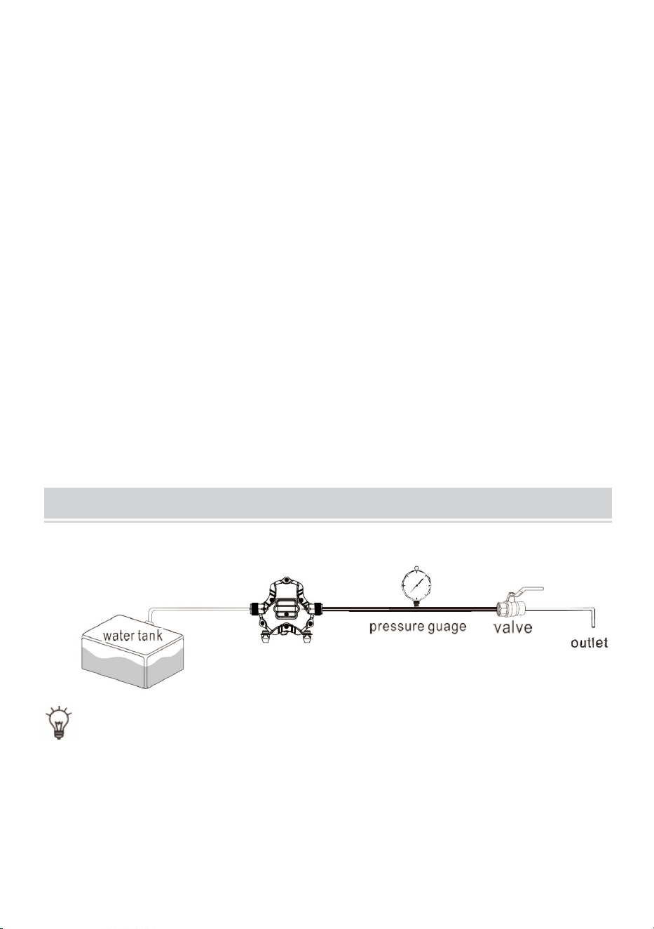
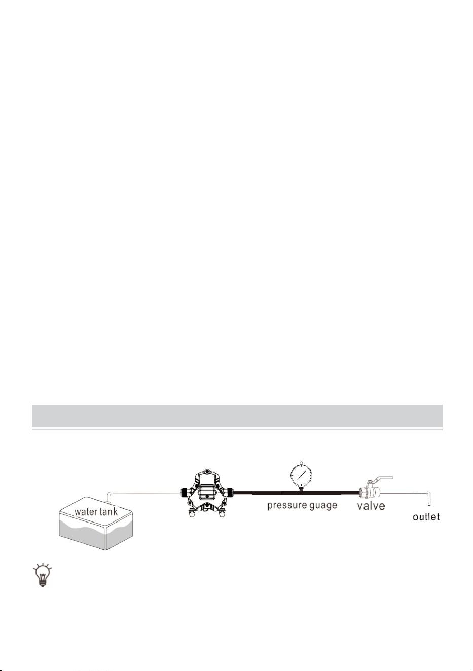
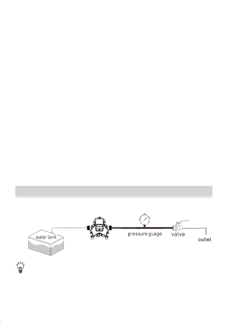
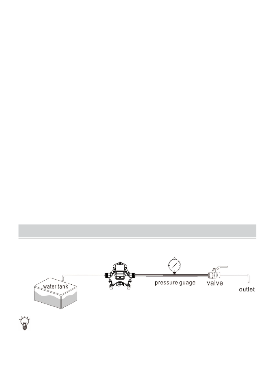
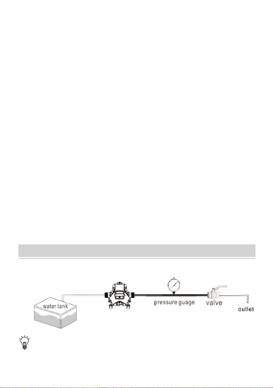
INSTALL THE PUMP AS THE PICTURE 1
TIP: The range of pressure regulation is limited. Please operate under the
guidance of professional technicians, otherwise the machine may not work
normally.
- 9 -
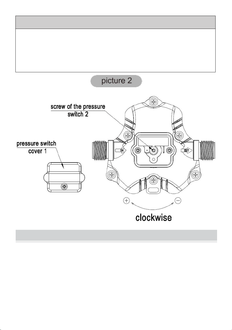
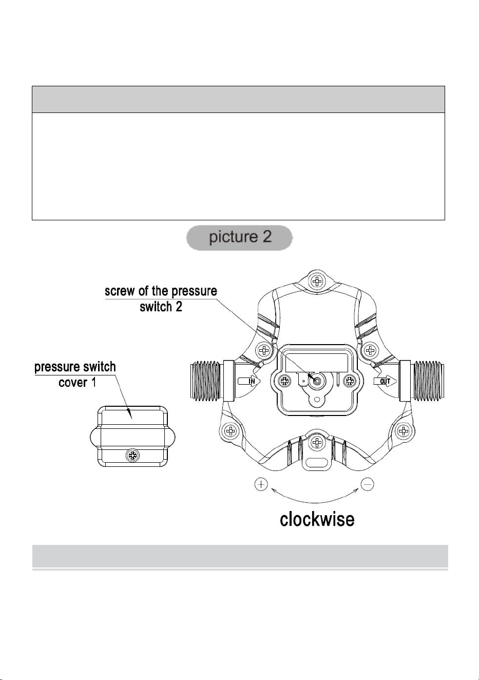
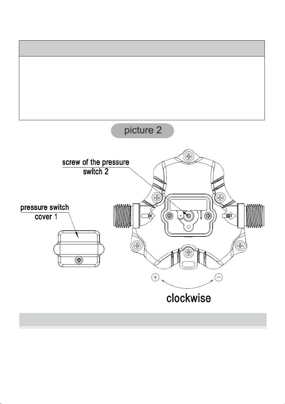
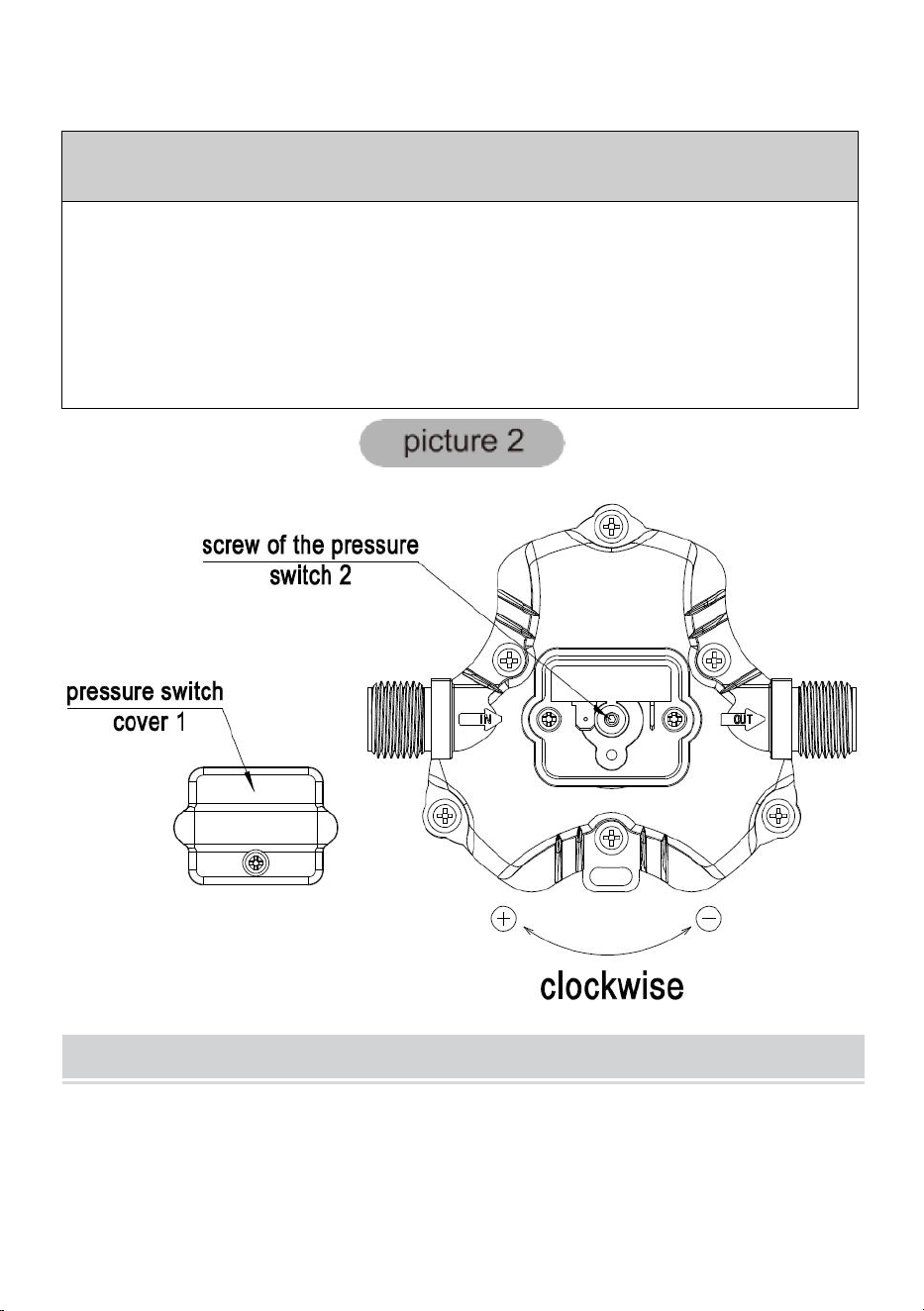
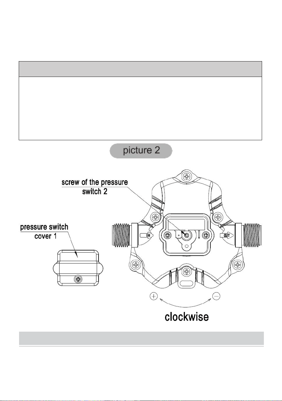
ADJUSTING THE PUMP'S SHUT-OFF PRESSURE:
Step 1:Remove pressure switch cover(No.1)
Step 2: Fine-tune the pressure adjustment screw (serial number 2) of the
pressure switch with a 2mm wrench, if you want to increase the pressure, turn
it clockwise, if you want to decrease the pressure, turn it counterclockwise.
Step 3: Install the pressure switch cover (No.1)
ABOUT THE BYPASS
Please consult a professional technician in case the bypass needs
adjustment. Improper adjustment of the bypass may damage the pump.
The bypass comes preset for optimal operation of the pump. If your
application calls for a different setting for the bypass, you may change it
yourself. Carefully tighten the screw to increase or loosen the screw to
decrease the minimum operating pressure of the bypass.

- 10 -
CAUTION
Please do follow the instruction manual to install the product. Any action
outside what is recommended in this manual may bring damage to the
pump.
*There are any minor changes to the numbers included in the user manual
without prior notice.


- 12 -
Technique Certificat d'assistance et de garantie électronique
www.vevor.com/support
POMPE À EAU POTABLE 12 VOLTS
MODÈLE : NMDP33-G18-60-12 /
NMDP33-G30-50-12 / NMDP33-G35-50-12
We continue to be committed to provide you tools with competitive price.
"Save Half", "Half Price" or any other similar expressions used by us only represents an
estimate of savings you might benefit from buying certain tools with us compared to the major
top brands and does not necessarily mean to cover all categories of tools offered by us. You
are kindly reminded to verify carefully when you are placing an order with us if you are
actually saving half in comparison with the top major brands.
- 1 -
MODÈLE: NMDP33-G18-60-12 / NMDP33-G30-50-12 /
NMDP33-G35-50-12
Have product questions? Need technical support? Please feel free to
contact us:
Technical Support and E-Warranty Certificate
www.vevor.com/support
NEED HELP? CONTACT US!
12 VOLT POTABLE
WATER PUMP
- 2 -
This is the original instruction, please read all manual instructions
carefully before operating. VEVOR reserves a clear interpretation of our
user manual. The appearance of the product shall be subject to the
product you received. Please forgive us that we won't inform you again if
there are any technology or software updates on our product.
Avertissement - Pour réduire le risque de blessure, l'utilisateur doit
lire attentivement le manuel d'instructions.
ÉLIMINATION CORRECTE
Ce produit est soumis aux dispositions de la directive européenne
2012/19/UE. Le symbole représentant une poubelle à roulettes
barrée indique que le produit doit faire l'objet d'une collecte sélective
des déchets dans l'Union européenne. Cela s'applique au produit et
à tous les accessoires marqués de ce symbole. Les produits
marqués comme tels ne peuvent pas être jetés avec les déchets
ménagers normaux, mais doivent être déposés dans un point de
collecte pour le recyclage des appareils électriques et électroniques.
La série 33 est une machine économique conçue pour la flexibilité. La série à
3 chambres est notre pompe à eau robuste. Elle fournit un débit d'eau à
volume élevé avec un cycle de pompage réduit, grâce au grand diaphragme à
trois chambres. Avec interrupteur à la demande. La série 33 est disponible en
trois tailles, 1,8 GPM/60 psi, 3,0 GPM/50 psi et 3,5 GPM/50 psi, pour répondre
à vos exigences particulières avec des performances prévisibles positives. La
série 33 peut réduire les cycles rapides et permettre à l'eau de refluer du côté
sortie vers le côté entrée de la pompe. Nous proposons également une variété
de raccords et de filtres faciles à connecter.
PRODUCT SPECICATIONS
Propriété
Caractéristiques

- 3 -
NMDP33-
G18-60-12
NMDP33-
G30-50-12
NMDP33-
G35-50-12
Tension nominale
12 V CC
12 V CC
12 V CC
Pression nominale
60 PSI
50 PSI
50 PSI
Numéro de chambre
3 pièces
3 pièces
3 pièces
Débit max.
1,8 GPM
3,0 GPM
3,5 GPM
Diamètre
d'entrée/sortie
1/2" MNPT
1/2" MNPT
1/2" MNPT
Une liste de fonctionnalités incroyable, des composants de haute qualité et
des performances étonnantes. La conception à trois chambres à grand
volume, entraînée par un moteur robuste, produit des débits de 1,8 GPM/3,0
GPM/3,5 GPM, capable de s'auto-amorcer jusqu'à 6 pieds verticaux et peut
fonctionner à sec, ce qui en fait le leader du rapport prix/performance. Cette
pompe offre également une variété de raccords et de filtres faciles à
connecter.
FEATURES
·Pompe à membrane à 3 chambres
·Service continu
·Modèle de montage standard industriel
· Fonctionnement à sec pour des charges de travail normales
·Automatique : contrôlé par pressostat
·Auto-amorçant
·Fonctionnement silencieux
·Protection contre l'allumage
APPLICATIONS
· Système d'eau sous pression pour yacht/camping-car/caravane
· Appareils de pulvérisation (pulvérisateurs montés sur véhicule,
pulvérisateurs électriques)
· Machines de nettoyage, humidificateurs, purification de l'eau, appareils

- 4 -
médicaux
· Remplissage de boissons alimentaires et transfert de liquides
· Système d'eau solaire
· Tout autre système de pressurisation
INSTALLATION
Matériels
1. pompe à membrane avec accessoires associés
2. (au moins) morceaux de tuyaux flexibles renforcés, avec une résistance à
l'effondrement deux fois supérieure à la pression d'effondrement à l'entrée (le
tuyau doit avoir au moins 1/2" de diamètre)
3. colliers de serrage et vis en acier inoxydable
4. vis pour fixer la pompe à la surface de montage
1 interrupteur de coupure électrique
1 fusible
1 tournevis
1 outil de coupe puissant pour les tubes (si vous le souhaitez)Ruban téflon
ou produit d'étanchéité
Installation
1. La pompe peut être montée dans n'importe quelle position. Si elle est
montée verticalement, la tête de pompe doit être en position basse pour éviter
toute fuite dans le carter du moteur en cas de dysfonctionnement.
2. Fixez les pieds, mais ne les comprimez pas. Un serrage excessif des vis de
fixation peut réduire leur capacité à dissiper le bruit et les vibrations.
3. Les tuyaux d'entrée et de sortie doivent être renforcés avec un diamètre
intérieur de 1/2" (13 mm) . Le diamètre des lignes d'alimentation de dérivation
et individuelles à partir de la sortie ne doit pas être inférieur à 3/8" (10 mm).
4. Raccordez le système à l'aide de tubes flexibles tressés à haute pression (2
x la puissance de la pompe) pour minimiser les vibrations et le bruit.
5. N'appliquez pas de pression d'entrée supérieure à 30 psi. En général,
essayez d'éviter complètement toute pression d'entrée.

- 5 -
6. Évitez les pliures ou les raccords qui pourraient entraîner des restrictions
excessives.
7. Le filtre doit être fixé au côté entrée.
8. Les raccords doivent être fixés pour éviter les fuites
9. Utilisez des colliers aux deux extrémités du tuyau pour éviter les fuites d’air
dans la conduite d’eau.
10. Si un clapet anti-retour est installé dans la plomberie, il doit avoir une
pression de rupture ne dépassant pas 2 psi.
11. Si vous appliquez un produit d'étanchéité ou du ruban de plomberie, veillez
à ne pas en mettre trop. serrer, car ils pourraient être aspirés.
12. Cette pompe doit être câblée sur son propre circuit dédié. Connectez le
câble positif (rouge) à la borne positive de votre batterie et le câble négatif
(noir) à la borne négative de votre batterie.
13. Dans un endroit facilement accessible, installez un interrupteur pour
contrôler l'alimentation électrique de la pompe. Éteignez la pompe lorsqu'elle
n'est pas utilisée pendant une période prolongée ou lorsque le réservoir est
vide.
14. Le circuit électrique doit être protégé par un dispositif de protection contre
les surintensités (fusible) sur le câble positif. Cette pompe nécessite un fusible
de 15 ampères.
15. Le circuit de la pompe ne doit inclure aucune autre charge électrique.
16. La pompe d'alimentation en eau n'étant pas indispensable, reportez-vous
au tableau des câbles sous les informations électriques. Assurez-vous d'avoir
le calibre de câble adapté à la longueur de câble que vous utilisez.
17. Après l'installation, vérifiez la tension du moteur de la pompe. La tension
doit être vérifiée lorsque la pompe est en fonctionnement. La pleine tension
doit être disponible au niveau du moteur de la pompe à tout moment.
Remarques
1. Il est recommandé d'utiliser un tuyau flexible pour l'eau potable ou un tube
PEX plutôt qu'une tuyauterie rigide au niveau de la pompe. Si vous choisissez
d'utiliser une tuyauterie rigide, prévoyez une courte longueur de tuyau entre le
tuyau et la pompe pour éviter le bruit et les vibrations.

- 6 -
2. Nous faisons Nous déconseillons l'utilisation de ferrures métalliques. Dans
la mesure du possible, utilisez les ferrures en plastique fournies.
3. Ne réglez pas le bypass personnellement sans l’aide d’un technicien.
4. Le manque de désinfection et d'entretien est l'une des principales raisons
des performances médiocres de la pompe. Veuillez effectuer l'entretien et
l'hivernage de la pompe à des moments appropriés, en particulier avant et
après une période de stockage.
ACCESSORIES
1 thème
Quantité
NMDP33-
G18-60-12
NMDP33-
G30-50-12
NMDP33-
G35-50-12
Manuel
1
1
1
Adaptateur de tuyau
x
2
2
Filtre
x
1
1
Boulon hexagonal
x
1
1
Ruban d'étanchéité
x
1
1
EXPLODED VIEWS

- 7 -
CLÉ
Description
Quantité
UN
Ensemble de tête de pompe
1
B
Ensemble de soupapes
1
C
Assemblage de diaphragme
1
D
Ensemble moteur
1
1
Interrupteur à pression
1
2
Diaphragme du pressostat
1
3
Noyau de valve
1
4
Tête de pompe
1
5
Diaphragme
1
6
Pied en caoutchouc
1
7
Moteur
1
PRODUCT SIZE

- 8 -
TROUBLESHOOTING
DÉBIT PULSÉ - LA POMPE FONCTIONNE PAR CYCLES DE
MARCHE ET D'ARRÊT
·Vérifiez que les lignes ne sont pas pliées.
·Les conduites ou les raccords de plomberie sont peut-être trop petits.
·Nettoyer les robinets et les filtres.
·Vérifiez l’étanchéité des raccords pour détecter les fuites d’air.
DÉFAUT D'AMORÇAGE MAIS LE MOTEUR FONCTIONNE - PAS
DE DÉCHARGE DE LA POMPE
·Conduite d’admission ou de refoulement restreinte.
·Fuite d’air dans la conduite d’admission.
·Membrane de pompe perforée
·L'alimentation initiale en ampères n'est pas suffisante pour démarrer
correctement le moteur.
·Des débris obstruent les valves.
·Fissure dans le boîtier de la pompe.
LE MOTEUR NE S'ALLUME PAS
· Câblage desserré ou incorrect.
· Le circuit de la pompe n’a pas de puissance.
· Fusible grillé.
· Pressostat défectueux.
· Moteur défectueux.
- 9 -
LA POMPE NE S'ARRÊTE PAS APRÈS LA FERMETURE DE TOUS
LES APPAREILS
· Diaphragme perforé.
· Fuite de la conduite de refoulement.
· Pressostat défectueux.
· Tension insuffisante.
· Vannes obstruées dans la tête de pompe.
FAIBLE DÉBIT ET PRESSION
· Fuite d’air à l’admission de la pompe.
· Accumulation de débris à l’intérieur de la pompe ou de la plomberie.
· Roulement de pompe usé (éventuellement accompagné d'un bruit fort).
· Diaphragme perforé.
· Moteur défectueux.
BRUYANT
·Vérifiez si les pieds de montage sont trop comprimés.
· La surface de montage est-elle flexible ? Si c'est le cas, cela peut entraîner
du bruit.
·Vérifiez que la tête/les vis ne sont pas desserrées.
· Si la pompe est raccordée à un tuyau rigide, elle peut transmettre le bruit plus
facilement.
INSTALL THE PUMP AS THE PICTURE 1
CONSEIL : La plage de réglage de la pression est limitée. Veuillez faire
fonctionner l'appareil sous la supervision de techniciens professionnels, sinon
la machine risque de ne pas fonctionner normalement.
- 10 -
RÉGLAGE DE LA PRESSION D'ARRÊT DE LA POMPE :
Étape 1 : Retirez le couvercle du pressostat (n° 1)
Étape 2 : Ajustez finement la vis de réglage de la pression (numéro de série 2)
du pressostat avec une clé de 2 mm, si vous souhaitez augmenter la pression,
tournez-la dans le sens des aiguilles d'une montre, si vous souhaitez diminuer
la pression, tournez-la dans le sens inverse des aiguilles d'une montre.
Étape 3 : Installez le couvercle du pressostat (n° 1)
ABOUT THE BYPASS
Veuillez consulter un technicien professionnel au cas où le bypass serait
nécessaire. ajustement. Un réglage incorrect de la dérivation peut
endommager le pompe.

- 11 -
Le bypass est préréglé pour un fonctionnement optimal de la pompe . Si
votre l'application nécessite un réglage différent pour le bypass, vous
pouvez changez-le vous-même. Serrez soigneusement la vis pour
augmenter ou desserrer la vis pour diminuer la pression minimale de
fonctionnement du by-pass.
CAUTION
Veuillez suivre le manuel d'instructions pour installer le produit. toute action
en dehors de ce qui est recommandé dans ce manuel peut entraîner
dommage à la pompe.
*Des modifications mineures peuvent être apportées aux numéros inclus
dans le manuel d'utilisation sans préavis.


- 13 -
Technisch Support und E-Garantie-Zertifikat
www.vevor.com/support
12-VOLT-TRINKWASSERPUMPE
MODELL: NMDP33-G18-60-12 /
NMDP33-G30-50-12 / NMDP33-G35-50-12
We continue to be committed to provide you tools with competitive price.
"Save Half", "Half Price" or any other similar expressions used by us only represents an
estimate of savings you might benefit from buying certain tools with us compared to the major
top brands and does not necessarily mean to cover all categories of tools offered by us. You
are kindly reminded to verify carefully when you are placing an order with us if you are
actually saving half in comparison with the top major brands.

- 1 -
MODELL: NMDP33-G18-60-12 / NMDP33-G30-50-12 /
NMDP33-G35-50-12
Have product questions? Need technical support? Please feel free to
contact us:
Technical Support and E-Warranty Certificate
www.vevor.com/support
NEED HELP? CONTACT US!
12 VOLT POTABLE
WATER PUMP

- 2 -
This is the original instruction, please read all manual instructions
carefully before operating. VEVOR reserves a clear interpretation of our
user manual. The appearance of the product shall be subject to the
product you received. Please forgive us that we won't inform you again if
there are any technology or software updates on our product.
Warnung: Um das Verletzungsrisiko zu verringern, muss der
Benutzer die Bedienungsanleitung sorgfältig lesen.
KORREKTE ENTSORGUNG
Dieses Produkt unterliegt den Bestimmungen der europäischen
Richtlinie 2012/19/EU. Das Symbol einer durchgestrichenen
Mülltonne weist darauf hin, dass dieses Produkt in der Europäischen
Union einer getrennten Müllentsorgung unterliegt. Dies gilt für das
Produkt und alle mit diesem Symbol gekennzeichneten Zubehörteile.
So gekennzeichnete Produkte dürfen nicht im normalen Hausmüll
entsorgt werden, sondern müssen an einer Sammelstelle für das
Recycling von elektrischen und elektronischen Geräten abgegeben
werden.
Die 33er-Serie ist ein wirtschaftliches Arbeitstier und auf Flexibilität ausgelegt.
Die 3-Kammer-Serie ist unsere Hochleistungs-Wasserpumpe. Dank der
großen Dreikammermembran bietet sie einen hohen Wasserdurchfluss bei
reduziertem Pumpenzyklus. Mit Bedarfsschalter. Die 33er-Serie ist in drei
Größen erhältlich: 1,8 GPM/60 psi, 3,0 GPM/50 psi und 3,5 GPM/50 psi. Sie
erfüllt Ihre speziellen Anforderungen mit einer positiven, vorhersehbaren
Leistung. Die 33er-Serie kann schnelle Zyklen reduzieren und Wasser von der
Auslassseite zur Einlassseite der Pumpe zurückfließen lassen. Wir bieten
auch eine Vielzahl von leicht anzuschließenden Armaturen und Filtern an.
PRODUCT SPECICATIONS

- 3 -
Eigentum
Technische Daten
NMDP33-
G18-60-12
NMDP33-
G30-50-12
NMDP33-
G35-50-12
Nennspannung
Gleichstrom
12 V
Gleichstrom
12 V
Gleichstrom
12 V
Nenndruck
60 PSI
50 PSI
50 PSI
Nummer der Kammer
3 STK
3 STK
3 STK
Max. Durchfluss
1,8 GPM
3,0 GPM
3,5 GPM
Einlass-/Auslassdurchmess
er
1/2 Zoll
Innengewind
e
1/2 Zoll
Innengewind
e
1/2 Zoll
Innengewind
e
Eine unglaubliche Funktionsliste, hochwertige Komponenten und erstaunliche
Leistung. Das Dreikammer-Hochvolumendesign, angetrieben von einem
Hochleistungsmotor, erzeugt Durchflussraten von 1,8 GPM/3,0 GPM/3,5 GPM,
kann bis zu 6 Fuß vertikal selbstansaugen und trocken laufen, was es zum
Preis-Leistungs-Führer macht. Diese Pumpe bietet außerdem eine Vielzahl
leicht anzuschließender Anschlüsse und Filter.
FEATURES
·3 -Kammer Membranpumpe
·Dauerbetrieb
· Montagemuster nach Industriestandard
· Trockenlauffähig bei normaler Arbeitsbelastung
·Automatisch: gesteuert durch Druckschalter
· Selbstansaugend
· Leiser Betrieb
·Zündgeschützt
APPLICATIONS
· Druckwassersystem für Yachten/Wohnmobile/Caravans
· Spritzenvorrichtungen (Fahrzeugspritzen, Elektrospritzen)

- 4 -
· Reinigungsmaschinen Luftbefeuchter Wasseraufbereitung, medizinische
Geräte
· Abfüllen von Lebensmitteln und Getränken sowie Flüssigkeitstransfer
· Solar-Wassersystem
· Jedes andere Drucksystem
INSTALLATION
Materialien
1.Membranpumpe mit entsprechendem Zubehör
2. (mindestens) Stücke flexibler, verstärkter Schlauchleitungen mit einer
Bruchfestigkeit, die dem doppelten Bruchdruck am Einlass entspricht (der
Schlauch muss einen Durchmesser von mindestens 1/2 Zoll haben)
3. Schlauchschellen und Schrauben aus Edelstahl
4. Schrauben zur Befestigung der Pumpe an der Montagefläche
1 elektrischer Trennschalter
1 Sicherung
1 Schraubendreher
1 starkes Schneidwerkzeug für Schläuche (falls gewünscht)Teflonband oder
Dichtungsmittel
Aufstellen
1. Die Pumpe kann in jeder beliebigen Position montiert werden. Bei vertikaler
Montage sollte der Pumpenkopf nach unten zeigen, um im Störungsfall ein
Auslaufen in das Motorgehäuse zu vermeiden.
2. Sichern Sie die Füße, ohne sie zusammenzudrücken. Wenn Sie die
Befestigungsschrauben zu fest anziehen, kann dies zu einer Verringerung
ihrer Fähigkeit führen, Geräusche und Vibrationen abzuleiten.
mit einem Innendurchmesser von 1/2 Zoll (13 mm) sein . Der Durchmesser
von Abzweigungen und einzelnen Versorgungsleitungen vom Ablauf darf nicht
kleiner als 3/8 Zoll (10 mm) sein.
4. Schließen Sie das System mit Hochdruckschläuchen (2 x Pumpenleistung)
und geflochtenen, flexiblen Schläuchen an, um Vibrationen und Lärm zu

- 5 -
minimieren.
5. Wenden Sie keinen Eingangsdruck über 30 psi an. Versuchen Sie generell,
jeglichen Eingangsdruck vollständig zu vermeiden.
6. Vermeiden Sie Knickstellen oder Verschraubungen, die zu übermäßigen
Einschränkungen führen könnten.
7. An der Einlassseite sollte ein Sieb angebracht sein.
8.Die Armaturen müssen gesichert werden, um Leckagen zu vermeiden
9.Verwenden Sie an beiden Enden des Schlauches Klemmen, um ein
Eindringen von Luft in die Wasserleitung zu verhindern.
10. Wenn in der Wasserleitung ein Rückschlagventil eingebaut ist, darf dessen
Öffnungsdruck nicht mehr als 2 psi betragen.
11. Wenn Sie Dichtungsmittel oder Klempnerband auftragen, achten Sie
darauf, nicht zu viel festziehen, da die Gefahr besteht, dass sie eingesaugt
werden.
12. Diese Pumpe sollte an einen eigenen Stromkreis angeschlossen werden.
Verbinden Sie das Pluskabel (rot) mit dem Pluspol Ihrer Batterie und das
Minuskabel (schwarz) mit dem Minuspol Ihrer Batterie.
13. Installieren Sie an einer leicht zugänglichen Stelle einen Schalter zur
Steuerung der Stromversorgung der Pumpe. Schalten Sie die Pumpe aus,
wenn sie längere Zeit nicht verwendet wird oder wenn der Tank leer ist.
14. Der Stromkreis sollte mit einem Überstromschutzgerät (Sicherung) im
Pluskabel geschützt werden. Diese Pumpe benötigt eine
15-Ampere-Sicherung.
15. Der Pumpenstromkreis sollte keine anderen elektrischen Lasten enthalten.
16. Da die Wasserversorgungspumpe nicht unbedingt erforderlich ist, sehen
Sie sich die Kabeltabelle unter den elektrischen Informationen an. Stellen Sie
sicher, dass Sie die richtige Kabelgröße für die von Ihnen verwendete
Kabellänge haben.
17. Überprüfen Sie nach der Installation die Spannung am Pumpenmotor. Die
Spannung sollte bei laufender Pumpe überprüft werden. Am Pumpenmotor
muss immer die volle Spannung anliegen.
Hinweise

- 6 -
1. Anstelle von starren Rohrleitungen an der Pumpe wird ein flexibler
Trinkwasserschlauch oder PEX-Rohr empfohlen. Wenn Sie sich für starre
Rohrleitungen entscheiden, installieren Sie ein kurzes Schlauchstück
zwischen dem Rohr und der Pumpe, um Lärm und Vibrationen zu vermeiden.
2. Wir tun Die Verwendung von Metallbeschlägen wird nicht empfohlen.
Verwenden Sie nach Möglichkeit die mitgelieferten Kunststoffbeschläge.
3. Passen Sie den Bypass nicht selbst ohne die Hilfe eines Technikers an.
4. Mangelnde Desinfektion und Wartung sind einer der Hauptgründe für die
Leistungsschwäche der Pumpe. Bitte führen Sie die Wartung durch und
machen Sie die Pumpe winterfest, insbesondere vor und nach einer Lagerzeit.
ACCESSORIES
1 Thema
Menge
NMDP33-
G18-60-12
NMDP33-
G30-50-12
NMDP33-
G35-50-12
Handbuch
1
1
1
Schlauchadapter
X
2
2
Filter
X
1
1
Sechskantschraube
X
1
1
Dichtungsband
X
1
1
EXPLODED VIEWS
- 7 -
SCHLÜSSEL
Beschreibung
Menge
A
Pumpenkopfbaugruppe
1
B
Ventilbaugruppe
1
C
Membranbaugruppe
1
D
Motormontage
1
1
Druckschalter
1
2
Membran des Druckschalters
1
3
Ventileinsatz
1
4
Pumpenkopf
1
5
Membran
1
6
Gummifuß
1
7
Motor
1
PRODUCT SIZE

- 8 -
TROUBLESHOOTING
PULSIERENDER DURCHFLUSS - PUMPENZYKLUS EIN UND
AUS
·Leitungen auf Knicke prüfen.
· Rohrleitungen oder Armaturen sind möglicherweise zu klein.
·Wasserhähne und Filter reinigen.
· Überprüfen Sie die Dichtheit der Anschlüsse auf Luftlecks.
Fehlgeschlagen beim Ansaugen, aber Motor läuft – keine
Pumpenentladung
· Einlass- oder Auslassleitung verstopft.
·Luftleck in der Ansaugleitung.
· Durchstochene Pumpenmembran
· Die anfängliche Amperezahl reicht nicht aus, um den Motor ausreichend zu
starten.
· Schmutz verstopft die Ventile.
·Riss im Pumpengehäuse.
MOTOR LÄSST SICH NICHT EINSCHALTEN
· Lose oder unsachgemäße Verkabelung.
· Der Pumpenkreis hat keinen Strom.
· Durchgebrannte Sicherung.
· Druckschalter defekt.
· Motor defekt.
- 9 -
Pumpe schaltet sich nicht ab, nachdem alle Armaturen geschlossen
sind
· Durchstochenes Zwerchfell.
· Leck in der Abflussleitung.
· Druckschalter defekt.
· Unzureichende Spannung.
· Verstopfte Ventile im Pumpenkopf.
NIEDRIGER DURCHFLUSS UND DRUCK
· Luftleck am Pumpeneinlass.
· Ansammlung von Schmutz in der Pumpe oder den Leitungen.
· Abgenutztes Pumpenlager (eventuell begleitet von lauten Geräuschen).
· Durchstochenes Zwerchfell.
· Motor defekt.
LAUT
·Prüfen Sie, ob die Montagefüße zu fest zusammengedrückt sind.
· Ist die Montagefläche flexibel? Wenn ja, kann es zu Geräuschen kommen.
·Auf lose Köpfe/Schrauben achten.
· Wenn die Pumpe an ein starres Rohr angeschlossen ist, kann es sein, dass
sie Geräusche leichter überträgt.
INSTALL THE PUMP AS THE PICTURE 1
T I P P I P: Der Druckregulierungsbereich ist begrenzt. Bitte lassen Sie
sich von professionellen Technikern anleiten, da die Maschine sonst
möglicherweise nicht normal funktioniert.
- 10 -
EINSTELLEN DES ABSCHALTDRUCKS DER PUMPE:
Schritt 1: Druckschalter-Abdeckung entfernen (Nr. 1)
Schritt 2: Stellen Sie die Druckeinstellschraube (Seriennummer 2) des
Druckschalters mit einem 2-mm-Schraubenschlüssel fein ein. Wenn Sie den
Druck erhöhen möchten, drehen Sie sie im Uhrzeigersinn, wenn Sie den Druck
verringern möchten, drehen Sie sie gegen den Uhrzeigersinn.
Schritt 3: Installieren Sie die Druckschalterabdeckung (Nr. 1)
ABOUT THE BYPASS
Bitte wenden Sie sich an einen professionellen Techniker, wenn der
Bypass Einstellung. Eine falsche Einstellung des Bypasses kann zu
Schäden am Pumpe.
Der Bypass ist für den optimalen Betrieb der Pumpe voreingestellt . Wenn

- 11 -
Ihr Wenn Ihre Anwendung eine andere Einstellung für den Bypass
erfordert, ändern Sie es selbst. Ziehen Sie die Schraube vorsichtig an, um
zu erhöhen oder zu lösen die Schraube zur Verringerung des
Mindestbetriebsdrucks des Bypass.
CAUTION
Bitte folgen Sie der Anleitung zur Installation des Produkts. Wenn Sie
andere Maßnahmen als die in diesem Handbuch empfohlenen ergreifen,
kann dies zu Beschädigung der Pumpe.
*Die in der Bedienungsanleitung enthaltenen Nummern können ohne
vorherige Ankündigung geringfügig geändert werden.


- 13 -
Tecnico Supporto e certificato di garanzia elettronica
www.vevor.com/support
POMPA PER ACQUA POTABILE DA 12 VOLT
MODELLO: NMDP33-G18-60-12 /
NMDP33-G30-50-12 / NMDP33-G35-50-12
We continue to be committed to provide you tools with competitive price.
"Save Half", "Half Price" or any other similar expressions used by us only represents an
estimate of savings you might benefit from buying certain tools with us compared to the major
top brands and does not necessarily mean to cover all categories of tools offered by us. You
are kindly reminded to verify carefully when you are placing an order with us if you are
actually saving half in comparison with the top major brands.

- 1 -
MODELLO: NMDP33-G18-60-12 / NMDP33-G30-50-12 /
NMDP33-G35-50-12
Have product questions? Need technical support? Please feel free to
contact us:
Technical Support and E-Warranty Certificate
www.vevor.com/support
NEED HELP? CONTACT US!
12 VOLT POTABLE
WATER PUMP

- 2 -
This is the original instruction, please read all manual instructions
carefully before operating. VEVOR reserves a clear interpretation of our
user manual. The appearance of the product shall be subject to the
product you received. Please forgive us that we won't inform you again if
there are any technology or software updates on our product.
Attenzione: per ridurre il rischio di lesioni, l'utente deve leggere
attentamente il manuale di istruzioni.
SMALTIMENTO CORRETTO
Questo prodotto è soggetto alle disposizioni della Direttiva europea
2012/19/UE. Il simbolo raffigurante un bidone della spazzatura
barrato indica che il prodotto richiede la raccolta differenziata dei
rifiuti nell'Unione europea. Ciò si applica al prodotto e a tutti gli
accessori contrassegnati con questo simbolo. I prodotti
contrassegnati come tali non possono essere smaltiti con i normali
rifiuti domestici, ma devono essere portati in un punto di raccolta per
il riciclaggio di dispositivi elettrici ed elettronici.
Un cavallo di battaglia economico, la serie 33 è progettata per la flessibilità. La
serie a 3 camere è la nostra pompa per acqua Heavy-Duty. Fornisce un flusso
d'acqua ad alto volume con cicli di pompaggio ridotti, grazie al grande
diaframma a tre camere. Con interruttore on-demand. La serie 33 è disponibile
in tre misure, 1,8 GPM/60 psi, 3,0 GPM/50 psi e 3,5 GPM/50 psi, soddisfa i
tuoi requisiti speciali con prestazioni positive e prevedibili. La serie 33 può
ridurre i cicli rapidi e consentire all'acqua di fluire di nuovo dal lato di uscita al
lato di ingresso della pompa. Offriamo anche una varietà di raccordi e filtri facili
da collegare.
PRODUCT SPECICATIONS
Proprietà
Specifiche

- 3 -
NMDP33-
G18-60-12
NMDP33-
NUMERO DI
MODELLO:
G30-50-12
NMDP33-
NUMERO DI
MODELLO:
G35-50-12
Tensione nominale
Corrente
continua
12V
Corrente
continua 12V
Corrente
continua 12V
Pressione nominale
60 psi
50 psi
50 psi
Numero di Camera
3 PZ
3 PZ
3 PZ
Portata massima
1,8 galloni al
minuto
3,0 galloni al
minuto
3,5 galloni al
minuto
Diametro di
ingresso/uscita
1/2"
filettatura
interna
1/2" filettatura
interna
1/2" filettatura
interna
Un elenco di caratteristiche incredibile, componenti di alta qualità, oltre a
prestazioni sorprendenti. Il design ad alto volume a tre camere, azionato da un
motore per impieghi gravosi, produce portate di 1,8 GPM/3,0 GPM/3,5 GPM,
in grado di autoadescarsi fino a 6 piedi verticali e può funzionare a secco, il
che la rende leader nel rapporto prezzo/prestazioni. Questa pompa offre
anche una varietà di raccordi e filtri facili da collegare.
FEATURES
·Pompa a membrana a 3 camere
·Servizio continuo
· Modello di montaggio standard industriale
·Funziona a secco per carichi di lavoro normali
·Automatico: controllato dal pressostato
·Autoadescante
·Funzionamento silenzioso
·Protetto contro l'accensione
APPLICATIONS

- 4 -
· Sistema di acqua pressurizzata per yacht/camper/roulotte
· Dispositivi di irrorazione (irroratrici montate su veicoli, irroratrici elettriche)
· Macchine per la pulizia Umidificatori per la depurazione dell'acqua,
apparecchiature mediche
· Riempimento di bevande alimentari e trasferimento di liquidi
· Sistema solare idrico
· Qualsiasi altro sistema di pressurizzazione
INSTALLATION
Materiali
1. pompa a membrana con relativi accessori
2. (almeno) pezzi di tubo flessibile rinforzato, con resistenza al collasso pari al
doppio della pressione di collasso in ingresso (il tubo deve avere un diametro
minimo di 1/2")
3. Fascette stringitubo e viti in acciaio inossidabile
4. viti per fissare la pompa alla superficie di montaggio
1 interruttore di interruzione elettrica
1 fusibile
1 cacciavite
1 utensile da taglio robusto per tubi (se desiderato) Nastro in teflon o
sigillante
Impostare
1. La pompa può essere montata in qualsiasi posizione. Se montata
verticalmente, la testa della pompa deve essere in posizione abbassata per
evitare perdite nella carcassa del motore in caso di malfunzionamento.
2. Fissare i piedini, ma non comprimerli. Un serraggio eccessivo delle viti di
fissaggio può ridurre la loro capacità di dissipare rumore e vibrazioni.
3. I tubi di ingresso e di uscita devono essere tubi rinforzati con diametro
interno di 1/2" (13 mm) . Il diametro delle diramazioni e delle singole linee di
alimentazione dall'uscita non deve essere inferiore a 3/8" (10 mm).
4. Collegare il sistema tramite tubi flessibili intrecciati ad alta pressione (2 volte

- 5 -
la portata della pompa) per ridurre al minimo vibrazioni e rumore.
5. Non applicare una pressione di ingresso superiore a 30 psi. In generale,
cercare di evitare completamente qualsiasi pressione di ingresso.
6. Evitare qualsiasi piega o raccordo che potrebbe causare restrizioni
eccessive.
7. Il filtro deve essere fissato sul lato di ingresso.
8. I raccordi devono essere fissati per evitare perdite
9. Utilizzare fascette su entrambe le estremità del tubo per evitare perdite
d'aria nella linea dell'acqua.
10. Se nell'impianto idraulico è installata una valvola di ritegno, la sua
pressione di apertura non deve essere superiore a 2 psi .
11. Se si applica un sigillante o un nastro idraulico, fare attenzione a non
esagerare stringere, perché potrebbero essere risucchiati.
12. Questa pompa dovrebbe essere cablata sul suo circuito dedicato. Collega
il cavo positivo (rosso) al terminale positivo della batteria e il cavo negativo
(nero) al terminale negativo della batteria.
13. In un luogo facilmente accessibile, installare un interruttore per controllare
l'elettricità della pompa. Spegnere la pompa quando non viene utilizzata per
lunghi periodi o quando il serbatoio è vuoto.
14.Il circuito elettrico deve essere protetto con un dispositivo di protezione da
sovracorrente (fusibile) nel cavo positivo. Questa pompa richiede un fusibile
da 15 amp.
15. Il circuito della pompa non deve includere altri carichi elettrici.
16. Poiché la pompa di alimentazione dell'acqua non è essenziale, fare
riferimento alla tabella dei cavi sotto le informazioni elettriche. Assicurarsi di
avere le dimensioni corrette dei cavi per la lunghezza del cavo che si sta
utilizzando.
17.Dopo l'installazione, controllare la tensione al motore della pompa. La
tensione deve essere controllata quando la pompa è in funzione. A volte, la
tensione completa deve essere disponibile al motore della pompa.
Appunti
1. Si consiglia di utilizzare un tubo flessibile per acqua potabile o un tubo PEX

- 6 -
anziché una tubazione rigida alla pompa. Se si sceglie di utilizzare una
tubazione rigida, prevedere un breve tratto di tubo tra il tubo e la pompa per
evitare rumore e vibrazioni.
2. Noi facciamo sconsigliamo l'uso di raccordi metallici. Quando possibile,
utilizzare i raccordi in plastica forniti.
3. Non regolare personalmente il bypass senza l'aiuto di un tecnico.
4. La mancanza di sanificazione e manutenzione è una delle principali cause
delle scarse prestazioni della pompa. Si prega di effettuare la manutenzione e
di mettere la pompa in condizioni invernali nei momenti appropriati, in
particolare prima e dopo un periodo di stoccaggio.
ACCESSORIES
1 tema
Quantità
NMDP33-
G18-60-12
NMDP33-
G30-50-12
NMDP33-
G35-50-12
Manuale
1
1
1
Adattatore per tubo
X
2
2
Filtro
X
1
1
Bullone esagonale
X
1
1
Nastro sigillante
X
1
1
EXPLODED VIEWS

- 7 -
CHIAVE
Descrizione
Quantità
UN
Gruppo testa pompa
1
B
Gruppo valvola
1
C
Gruppo diaframma
1
D
Montaggio motore
1
1
Interruttore di pressione
1
2
Diaframma del pressostato
1
3
Nucleo della valvola
1
4
Testa della pompa
1
5
Diaframma
1
6
Piede di gomma
1
7
Motore
1
PRODUCT SIZE
- 8 -
TROUBLESHOOTING
FLUSSO PULSANTE - CICLI DI ACCENSIONE E SPEGNIMENTO
DELLA POMPA
·Controllare che le linee non siano piegate.
·Le tubazioni idrauliche o i raccordi potrebbero essere troppo piccoli.
·Pulire rubinetti e filtri.
·Controllare la tenuta dei raccordi per eventuali perdite d'aria.
MANCATO ADESCAMENTO MA IL MOTORE FUNZIONA -
NESSUNA SCARICA DELLA POMPA
·Linea di aspirazione o di scarico ostruita.
·Perdita d'aria nella linea di aspirazione.
· Membrana della pompa forata
·L'amperaggio iniziale non è sufficiente per avviare correttamente il motore.
·Detriti intasano le valvole.
·Crepa nell'alloggiamento della pompa.
IL MOTORE NON SI ACCENDE
· Cablaggio allentato o non corretto.
· Il circuito della pompa non è alimentato.
· Fusibile bruciato.
· Pressostato guasto.
· Motore difettoso.
LA POMPA NON SI SPEGNE DOPO CHE TUTTI GLI APPARECCHI

- 9 -
SONO STATI CHIUSI
· Diaframma perforato.
· Perdita nella linea di scarico.
· Pressostato difettoso.
· Tensione insufficiente.
· Valvole ostruite nella testa della pompa.
BASSO FLUSSO E PRESSIONE
· Perdita d'aria all'aspirazione della pompa.
· Accumulo di detriti all'interno della pompa o delle tubature.
· Cuscinetto della pompa usurato (eventualmente accompagnato da forte
rumore).
· Diaframma perforato.
· Motore difettoso.
RUMOROSO
·Controllare che i piedini di montaggio non siano troppo compressi.
· La superficie di montaggio è flessibile? In tal caso, potrebbe causare rumore.
·Controllare che non vi siano viti/testa allentate.
· Se la pompa è collegata tramite un tubo rigido, il rumore potrebbe essere
trasmesso più facilmente.
INSTALL THE PUMP AS THE PICTURE 1
SUGGERIMENTO : La gamma di regolazione della pressione è limitata.
Operare sotto la guida di tecnici professionisti, altrimenti la macchina potrebbe
non funzionare normalmente .
- 10 -
REGOLAZIONE DELLA PRESSIONE DI ARRESTO DELLA
POMPA:
Fase 1: rimuovere il coperchio del pressostato (n. 1)
Fase 2: Regolare con precisione la vite di regolazione della pressione (numero
di serie 2) del pressostato con una chiave da 2 mm: se si desidera aumentare la
pressione, ruotarla in senso orario, se si desidera diminuirla, ruotarla in senso
antiorario.
Fase 3: Installare il coperchio del pressostato (n. 1)
ABOUT THE BYPASS
Si prega di consultare un tecnico professionista nel caso in cui sia
necessario il bypass aggiustamento. Una regolazione non corretta del
bypass può danneggiare il pompa.
Il bypass è preimpostato per un funzionamento ottimale della pompa . Se il

- 11 -
tuo l'applicazione richiede un'impostazione diversa per il bypass, è
possibile cambialo tu stesso. Stringi con attenzione la vite per aumentare o
allentare la vite per diminuire la pressione minima di esercizio del
bypassare.
CAUTION
Si prega di seguire il manuale di istruzioni per installare il prodotto.
Qualsiasi un'azione al di fuori di quanto raccomandato in questo manuale
può portare danni alla pompa.
*I numeri riportati nel manuale utente potrebbero subire piccole modifiche
senza preavviso.


- 13 -
Técnico Certificado de soporte y garantía electrónica
www.vevor.com/support
BOMBA DE AGUA POTABLE DE 12 VOLTIOS
MODELO: NMDP33-G18-60-12 /
NMDP33-G30-50-12 / NMDP33-G35-50-12
We continue to be committed to provide you tools with competitive price.
"Save Half", "Half Price" or any other similar expressions used by us only represents an
estimate of savings you might benefit from buying certain tools with us compared to the major
top brands and does not necessarily mean to cover all categories of tools offered by us. You
are kindly reminded to verify carefully when you are placing an order with us if you are
actually saving half in comparison with the top major brands.

- 1 -
MODELO: NMDP33-G18-60-12 / NMDP33-G30-50-12 /
NMDP33-G35-50-12
Have product questions? Need technical support? Please feel free to
contact us:
Technical Support and E-Warranty Certificate
www.vevor.com/support
NEED HELP? CONTACT US!
12 VOLT POTABLE
WATER PUMP
- 2 -
This is the original instruction, please read all manual instructions
carefully before operating. VEVOR reserves a clear interpretation of our
user manual. The appearance of the product shall be subject to the
product you received. Please forgive us that we won't inform you again if
there are any technology or software updates on our product.
Advertencia: Para reducir el riesgo de lesiones, el usuario debe leer
atentamente el manual de instrucciones.
ELIMINACIÓN CORRECTA
Este producto está sujeto a las disposiciones de la Directiva Europea
2012/19/UE. El símbolo que muestra un contenedor de basura
tachado indica que el producto requiere una recogida selectiva de
residuos en la Unión Europea. Esto se aplica al producto y a todos
los accesorios marcados con este símbolo. Los productos marcados
como tales no pueden desecharse con los residuos domésticos
normales, sino que deben llevarse a un punto de recogida para
reciclar dispositivos eléctricos y electrónicos.
La Serie 33 es una bomba de trabajo económica diseñada para brindar
flexibilidad. La serie de 3 cámaras es nuestra bomba de agua para trabajo
pesado. Proporciona un flujo de agua de alto volumen con ciclos de bombeo
reducidos, gracias al diafragma grande de tres cámaras. Con interruptor a
pedido. La Serie 33 está disponible en tres tamaños, 1.8 GPM/60 psi, 3.0
GPM/50 psi y 3.5 GPM/50 psi, y satisface sus requisitos especiales con un
rendimiento predecible positivo. La Serie 33 puede reducir los ciclos rápidos y
permitir que el agua fluya de regreso desde el lado de salida al lado de
entrada de la bomba. También ofrecemos una variedad de accesorios y filtros
de fácil conexión.
PRODUCT SPECICATIONS

- 3 -
Propiedad
Presupuesto
NMDP33-
G18-60-12
NMDP33-
G30-50-12
NMDP33-
G35-50-12
Voltaje nominal
12 V CC
12 V CC
12 V CC
Presión nominal
60 PSI
50 PSI
50 PSI
Número de Cámara
3 piezas
3 piezas
3 piezas
Caudal máx.
1,8 galones
por minuto
3,0 galones
por minuto
3,5 galones
por minuto
Diámetro de
entrada/salida
Rosca
macho de
1/2"
Rosca macho
de 1/2"
Rosca macho
de 1/2"
Una increíble lista de características, componentes de alta calidad y un
rendimiento asombroso. El diseño de alto volumen de tres cámaras,
impulsado por un motor de alta resistencia, produce caudales de 1,8 GPM/3,0
GPM/3,5 GPM, capaz de autocebarse hasta 6 pies verticales y puede
funcionar en seco, lo que la convierte en la líder en relación
precio-rendimiento. Esta bomba también ofrece una variedad de accesorios y
filtros de fácil conexión.
FEATURES
·Bomba de diafragma de 3 cámaras
·Servicio continuo
· Patrón de montaje estándar industrial
·Capacidad para funcionar en seco para cargas de trabajo normales
·Automático: controlado por presostato.
·Autocebante
·Funcionamiento silencioso
·Protegido contra ignición
APPLICATIONS
· Sistema de agua presurizada para yates, caravanas y vehículos recreativos

- 4 -
· Dispositivos de pulverización (pulverizadores montados en vehículos,
pulverizadores eléctricos)
· Máquinas de limpieza Humidificadores purificadores de agua, aparatos
médicos
· Llenado de alimentos y bebidas y transferencia de líquidos.
· Sistema de agua solar
· Cualquier otro sistema de presurización
INSTALLATION
Materiales
1.Bomba de diafragma con accesorios relacionados
2. (al menos) piezas de tubería de manguera reforzada y flexible, con una
resistencia al colapso del doble de la presión de colapso de entrada (la
manguera debe tener un diámetro mínimo de 1/2")
3. Abrazaderas y tornillos de manguera de acero inoxidable.
4. tornillos para fijar la bomba a la superficie de montaje
1 interruptor de corte eléctrico
1 fusible
1 destornillador
1 herramienta de corte fuerte para tubos (si se desea) Cinta de teflón o
sellador
Configuración
1. La bomba se puede montar en cualquier posición. Si se monta
verticalmente, el cabezal de la bomba debe estar en posición inferior para
evitar fugas en la carcasa del motor en caso de avería.
2. Fije las patas, pero no las comprima. Si aprieta demasiado los tornillos de
fijación, puede reducir su capacidad para disipar el ruido y la vibración.
3. Las mangueras de entrada y salida deben ser mangueras reforzadas con
un diámetro interior de 1/2" (13 mm) . El diámetro de las derivaciones y las
líneas de suministro individuales desde la salida no debe ser inferior a 3/8" (10
mm).

- 5 -
4. Conecte el sistema utilizando tuberías trenzadas y flexibles de alta presión
(2 veces la capacidad nominal de la bomba) para minimizar la vibración y el
ruido.
5. No aplique una presión de entrada superior a 30 psi. En general, trate de
evitar cualquier presión de entrada por completo.
6. Evite torceduras o accesorios que puedan causar restricciones excesivas.
7.El filtro debe estar conectado al lado de entrada.
8.Los accesorios deben estar asegurados para evitar fugas.
9. Utilice abrazaderas en ambos extremos de la manguera para evitar fugas
de aire en la línea de agua.
10. Si se instala una válvula de retención en la tubería, debe tener una presión
de apertura de no más de 2 psi.
11. Si aplica un sellador o cinta de plomería, tenga cuidado de no aplicar
demasiado. Apriete, ya que podrían ser succionados.
12. Esta bomba debe estar conectada a su propio circuito. Conecte el cable
positivo (rojo) al terminal positivo de la batería y el cable negativo (negro) al
terminal negativo de la batería.
13. En un lugar de fácil acceso, instale un interruptor para controlar la
electricidad que llega a la bomba. Apague la bomba cuando no la utilice
durante períodos prolongados o cuando el tanque esté vacío.
14. El circuito eléctrico debe estar protegido con un dispositivo de protección
contra sobrecorriente (fusible) en el cable positivo. Esta bomba requiere un
fusible de 15 amperios.
15. El circuito de la bomba no debe incluir ninguna otra carga eléctrica.
16. Como la bomba de suministro de agua no es esencial, consulte la tabla de
cables que se encuentra en la información eléctrica. Asegúrese de que el
tamaño de cable sea el correcto para la longitud del cable que está utilizando.
17. Después de la instalación, verifique el voltaje en el motor de la bomba. El
voltaje debe verificarse cuando la bomba esté en funcionamiento. El motor de
la bomba debe tener voltaje completo en todo momento.
Notas
1. Se recomienda utilizar una manguera de agua potable flexible o un tubo

- 6 -
PEX en lugar de una tubería rígida en la bomba. Si decide utilizar una tubería
rígida, coloque un tramo corto de manguera entre la tubería y la bomba para
evitar ruidos y vibraciones.
2. Nosotros lo hacemos No se recomienda el uso de accesorios de metal.
Cuando sea posible, utilice los accesorios de plástico provistos.
3. No ajuste el bypass personalmente sin la ayuda de un técnico.
4. La falta de desinfección y mantenimiento es una de las principales razones
del bajo rendimiento de la bomba. Realice el mantenimiento y prepare la
bomba para el invierno en los momentos adecuados, especialmente antes y
después de un período de almacenamiento.
ACCESSORIES
1 tema
Cantidad
NMDP33-
G18-60-12
NMDP33-
G30-50-12
NMDP33-
G35-50-12
Manual
1
1
1
Adaptador de
manguera
incógnita
2
2
Filtrar
incógnita
1
1
Perno hexagonal
incógnita
1
1
Cinta de sellado
incógnita
1
1
EXPLODED VIEWS
- 7 -
LLAVE
Descripción
Cantidad
A
Conjunto de cabezal de bomba
1
B
Conjunto de válvulas
1
do
Conjunto de diafragma
1
D
Conjunto de motor
1
1
Interruptor de presión
1
2
Diafragma del presostato
1
3
Núcleo de la válvula
1
4
Cabezal de bomba
1
5
Diafragma
1
6
Pie de goma
1
7
Motor
1
PRODUCT SIZE

- 8 -
TROUBLESHOOTING
FLUJO PULSANTE: LA BOMBA SE ENCIENDE Y APAGA CICLOS
·Compruebe que las líneas no tengan torceduras.
·Las líneas o accesorios de plomería pueden ser demasiado pequeños.
·Limpiar grifos y filtros.
·Verifique la estanqueidad del ajuste para detectar fugas de aire.
FALLA AL CEBAR PERO EL MOTOR FUNCIONA: NO HAY
DESCARGA DE LA BOMBA
·Línea de entrada o descarga restringida.
·Fuga de aire en la línea de admisión.
·Diafragma de bomba perforado
·El suministro de amperios inicial no es suficiente para arrancar
adecuadamente el motor.
·Los residuos obstruyen las válvulas.
·Grieta en la carcasa de la bomba.
EL MOTOR NO ENCIENDE
· Cableado suelto o inadecuado.
· El circuito de la bomba no tiene energía.
· Fusible quemado.
· Presostato averiado.
· Motor defectuoso.
LA BOMBA NO SE APAGA DESPUÉS DE QUE SE CERRARON
- 9 -
TODOS LOS ACCESORIOS
· Diafragma perforado.
· Fuga en la línea de descarga.
· Presostato defectuoso.
· Voltaje insuficiente.
· Válvulas obstruidas en el cabezal de la bomba.
BAJO CAUDAL Y PRESIÓN
· Fuga de aire en la entrada de la bomba.
· Acumulación de residuos en el interior de la bomba o la plomería.
· Cojinete de bomba desgastado (posiblemente acompañado de ruido fuerte).
· Diafragma perforado.
· Motor defectuoso.
RUIDOSO
·Compruebe si los pies de montaje están demasiado comprimidos.
¿ La superficie de montaje es flexible? Si es así, es posible que se produzca
ruido.
·Compruebe si hay cabezas o tornillos sueltos.
· Si la bomba está conectada con una tubería rígida, es posible que transmita
ruido con mayor facilidad.
INSTALL THE PUMP AS THE PICTURE 1
CONSEJO : El rango de regulación de presión es limitado. Utilice el
aparato bajo la supervisión de técnicos profesionales, de lo contrario, es
posible que no funcione con normalidad .

- 10 -
AJUSTE DE LA PRESIÓN DE APAGADO DE LA BOMBA:
Paso 1: Retire la cubierta del interruptor de presión (n.º 1)
Paso 2: Ajuste el tornillo de ajuste de presión (número de serie 2) del
presostato con una llave de 2 mm, si desea aumentar la presión gírelo en el
sentido de las agujas del reloj, si desea disminuir la presión gírelo en el sentido
contrario a las agujas del reloj.
Paso 3: Instale la cubierta del interruptor de presión (n.° 1)
ABOUT THE BYPASS
Por favor consulte a un técnico profesional en caso de que sea necesario
realizar el bypass. ajuste. Un ajuste incorrecto del bypass puede dañar el
bomba.
El bypass viene preajustado para un funcionamiento óptimo de la bomba .

- 11 -
Si su La aplicación requiere una configuración diferente para la derivación,
puede Cámbielo usted mismo. Apriete con cuidado el tornillo para
aumentar o aflojar. el tornillo para disminuir la presión mínima de
funcionamiento del derivación.
CAUTION
Siga el manual de instrucciones para instalar el producto. Acciones fuera
de lo recomendado en este manual pueden traer Daños a la bomba.
*Pueden producirse cambios menores en los números incluidos en el
manual del usuario sin previo aviso.


- 13 -
Techniczny Wsparcie i certyfikat e-gwarancji
www.vevor.com/support
POMPA DO WODY PITNEJ 12 V
MODELE: NMDP33-G18-60-12 /
NMDP33-G30-50-12 / NMDP33-G35-50-12
We continue to be committed to provide you tools with competitive price.
"Save Half", "Half Price" or any other similar expressions used by us only represents an
estimate of savings you might benefit from buying certain tools with us compared to the major
top brands and does not necessarily mean to cover all categories of tools offered by us. You
are kindly reminded to verify carefully when you are placing an order with us if you are
actually saving half in comparison with the top major brands.

- 1 -
MODEL: NMDP33-G18-60-12 / NMDP33-G30-50-12 /
NMDP33-G35-50-12
Have product questions? Need technical support? Please feel free to
contact us:
Technical Support and E-Warranty Certificate
www.vevor.com/support
NEED HELP? CONTACT US!
12 VOLT POTABLE
WATER PUMP

- 2 -
This is the original instruction, please read all manual instructions
carefully before operating. VEVOR reserves a clear interpretation of our
user manual. The appearance of the product shall be subject to the
product you received. Please forgive us that we won't inform you again if
there are any technology or software updates on our product.
Ostrzeżenie: Aby zminimalizować ryzyko obrażeń, użytkownik
powinien uważnie przeczytać instrukcję obsługi.
PRAWIDŁOWA UTYLIZACJA
Ten produkt podlega postanowieniom dyrektywy europejskiej
2012/19/UE. Symbol przedstawiający przekreślony kosz na śmieci
na kółkach oznacza, że produkt wymaga oddzielnej zbiórki odpadów
w Unii Europejskiej. Dotyczy to produktu i wszystkich akcesoriów
oznaczonych tym symbolem. Produktów oznaczonych w ten sposób
nie można wyrzucać razem ze zwykłymi odpadami domowymi, ale
należy je oddać do punktu zbiórki w celu recyklingu urządzeń
elektrycznych i elektronicznych.
Ekonomiczny koń roboczy, seria 33 została zaprojektowana z myślą o
elastyczności. Seria 3-komorowa to nasza pompa wodna Heavy-Duty.
Zapewnia ona przepływ wody o dużej objętości przy zmniejszonych cyklach
pompy, dzięki dużej membranie trójkomorowej. Z przełącznikiem na żądanie.
Seria 33 jest dostępna w trzech rozmiarach, 1,8 GPM/60 psi, 3,0 GPM/50 psi i
3,5 GPM/50 psi, spełniając Twoje specjalne wymagania dzięki pozytywnej
przewidywalnej wydajności. Seria 33 może zmniejszyć szybkie cykle i
umożliwić przepływ wody z powrotem ze strony wylotowej do strony wlotowej
pompy. Oferujemy również różnorodne łatwe do podłączenia złączki i filtry.
PRODUCT SPECICATIONS
Nieruchomość
Specyfikacje

- 3 -
NMDP33-
G18-60-12
NMDP33-
G30-50-12
NMDP33-
G35-50-12
Napięcie znamionowe
Prąd stały
12 V
Prąd stały 12
V
Prąd stały 12
V
Ciśnienie
znamionowe
60 PSI
50 PSI
50 PSI
Numer izby
3 SZT.
3 SZT.
3 SZT.
Maksymalny przepływ
1,8 galona
na minutę
3,0 galonów
na minutę
3,5 galona na
minutę
Średnica wlotu/wylotu
1/2" NPT
1/2" NPT
1/2" NPT
Niesamowita lista funkcji, wysokiej jakości komponenty i niesamowita
wydajność. Trójkomorowa konstrukcja o dużej objętości, napędzana
wytrzymałym silnikiem, zapewnia przepływ 1,8 GPM/3,0 GPM/3,5 GPM,
zdolna do samozasysania do 6 stóp w pionie i może pracować na sucho, co
czyni ją liderem pod względem stosunku ceny do wydajności. Ta pompa
oferuje również różnorodne, łatwe do podłączenia złączki i filtry.
FEATURES
·3-komorowa pompa membranowa
· Praca ciągła
·Przemysłowy - standardowy wzór montażu
· Możliwość pracy na sucho przy normalnych obciążeniach
·Automatyczny: sterowany za pomocą wyłącznika ciśnieniowego
·Samoczynne zalewanie
· Cicha praca
·Zabezpieczony przed zapłonem
APPLICATIONS
· System ciśnieniowego zasilania wodnego jachtu/kampera/przyczepy
kempingowej
· Osprzęt do opryskiwaczy (opryskiwacze montowane na pojazdach,

- 4 -
opryskiwacze elektryczne)
· Maszyny czyszczące, nawilżacze, oczyszczacze wody, aparatura medyczna
· Napełnianie napojów spożywczych i przenoszenie płynów
· System solarny do wody
· Każdy inny system ciśnieniowy
INSTALLATION
Przybory
1.pompa membranowa z akcesoriami
2. (przynajmniej) kawałki elastycznego, wzmocnionego węża rurowego o
wytrzymałości na zgniatanie dwukrotnie większej od ciśnienia zgniatania na
wlocie (wąż musi mieć minimalną średnicę 1/2"D)
3.Zaciski i śruby ze stali nierdzewnej
4. śruby mocujące pompę do powierzchni montażowej
1 wyłącznik elektryczny
1 bezpiecznik
1 śrubokręt
1 mocne narzędzie do cięcia rur (jeśli chcesz)Taśma teflonowa lub
uszczelniacz
Organizować coś
1. Pompa może być zamontowana w dowolnej pozycji. Jeśli jest zamontowana
pionowo, głowica pompy powinna być w pozycji dolnej, aby uniknąć wycieku
do obudowy silnika w przypadku awarii.
2. Zabezpiecz stopy, ale ich nie ściskaj. Zbytnie dokręcenie śrub
zabezpieczających może zmniejszyć ich zdolność do rozpraszania hałasu i
wibracji.
3. Węże wlotowe i wylotowe muszą być wzmocnione 1/2" (13 mm) I D.
Średnica odgałęzień i poszczególnych przewodów zasilających od wylotu nie
powinna być mniejsza niż 3/8" (10 mm).
4. Podłącz system do instalacji za pomocą przewodów wysokociśnieniowych
(o wydajności 2 x pompa), elastycznych przewodów z oplotem, aby

- 5 -
zminimalizować wibracje i hałas.
5. Nie stosuj ciśnienia wlotowego przekraczającego 30 psi. Generalnie staraj
się całkowicie unikać jakiegokolwiek ciśnienia wlotowego.
6. Unikaj wszelkich załamań i połączeń, które mogą powodować nadmierne
ograniczenia.
7. Sitko powinno być zamontowane po stronie wlotowej.
8.Złącza muszą być zabezpieczone, aby zapobiec przeciekom
9. Zamocuj zaciski na obu końcach węża, aby zapobiec przedostawaniu się
powietrza do przewodu wodnego.
10. Jeżeli w instalacji hydraulicznej zainstalowany jest zawór zwrotny , jego
ciśnienie otwarcia nie powinno przekraczać 2 psi.
11. Jeśli nakładasz uszczelniacz lub taśmę instalacyjną, uważaj, aby nie
nałożyć jej za dużo. zaciskać, ponieważ mogą zostać wciągnięte.
12. Ta pompa powinna być podłączona do własnego, dedykowanego obwodu.
Podłącz przewód dodatni (czerwony) do dodatniego zacisku akumulatora, a
przewód ujemny (czarny) do ujemnego zacisku akumulatora.
13. W łatwo dostępnym miejscu zainstaluj przełącznik, aby kontrolować
zasilanie elektryczne pompy. Wyłącz pompę, gdy nie jest używana przez
dłuższy czas lub gdy zbiornik jest pusty.
14. Obwód elektryczny powinien być zabezpieczony urządzeniem
zabezpieczającym przed przetężeniem (bezpiecznikiem) w przewodzie
dodatnim. Ta pompa wymaga bezpiecznika 15 A.
15. Obwód pompy nie powinien zawierać żadnych innych obciążeń
elektrycznych.
16. Ponieważ pompa doprowadzająca wodę nie jest niezbędna, zapoznaj się z
tabelą przewodów pod informacjami elektrycznymi. Upewnij się, że masz
odpowiedni rozmiar przewodu dla długości przewodu, którego używasz.
17. Po instalacji sprawdź napięcie na silniku pompy. Napięcie należy
sprawdzić, gdy pompa pracuje. Czasami na silniku pompy musi być dostępne
pełne napięcie.
Notatki
1. Zamiast sztywnego rurociągu przy pompie zaleca się elastyczny wąż do

- 6 -
wody pitnej lub rurę PEX. Jeśli zdecydujesz się na sztywne rury, zapewnij
krótki odcinek węża między rurą a pompą, aby uniknąć hałasu i wibracji.
2. Robimy nie zaleca się stosowania metalowych okuć. Jeśli to możliwe,
należy używać dostarczonych plastikowych okuć.
3. Nie dokonuj samodzielnej regulacji obejścia bez pomocy technika.
4. Brak dezynfekcji i konserwacji jest jedną z głównych przyczyn słabej
wydajności pompy. Przeprowadzaj konserwację i zimowanie pompy w
odpowiednich momentach, szczególnie przed i po okresie przechowywania.
ACCESSORIES
1 motyw
Ilość
NMDP33-
G18-60-12
NMDP33-
G30-50-12
NMDP33-
G35-50-12
Podręcznik
1
1
1
Adapter węża
X
2
2
Filtr
X
1
1
Śruba sześciokątna
X
1
1
Taśma uszczelniająca
X
1
1
EXPLODED VIEWS
- 7 -
KLAWISZ
Opis
Ilość
A
Zespół głowicy pompy
1
B
Zespół zaworów
1
C
Zespół membrany
1
D
Montaż silnika
1
1
Wyłącznik ciśnieniowy
1
2
Membrana wyłącznika
ciśnieniowego
1
3
Rdzeń zaworu
1
4
Głowica pompy
1
5
Membrana
1
6
Stopka gumowa
1
7
Silnik
1
PRODUCT SIZE
- 8 -
TROUBLESHOOTING
PRZEPŁYW PULSUJĄCY - CYKLE POMPY WŁĄCZONE I
WYŁĄCZONE
·Sprawdź przewody pod kątem załamań.
·Przewody lub złączki hydrauliczne mogą być zbyt małe.
·Wyczyść krany i filtry.
·Sprawdź szczelność połączeń, czy nie ma nieszczelności.
BRAK ZALEWANIA, ALE SILNIK DZIAŁA – BRAK WYPŁYWU Z
POMPY
·Ograniczony dopływ lub odpływ.
·Nieszczelność powietrza w przewodzie dolotowym.
· Przebita membrana pompy
·Początkowe natężenie prądu nie jest wystarczające do prawidłowego
uruchomienia silnika.
·Zanieczyszczenia zatykają zawory.
·Pęknięcie w obudowie pompy.
SILNIK NIE WŁĄCZA SIĘ
· Luźne lub nieprawidłowe okablowanie.
· Obwód pompy nie ma zasilania.
· Przepalony bezpiecznik.
· Uszkodzony wyłącznik ciśnieniowy.
· Wadliwy silnik.
- 9 -
POMPA NIE WYŁĄCZA SIĘ PO ZAMKNIĘCIU WSZYSTKICH
URZĄDZEŃ
· Przebita przepona.
· Nieszczelność przewodu wylotowego.
· Wadliwy wyłącznik ciśnieniowy.
· Niewystarczające napięcie.
· Zapchane zawory w głowicy pompy.
NISKI PRZEPŁYW I CIŚNIENIE
· Nieszczelność powietrza na wlocie pompy.
· Nagromadzenie się zanieczyszczeń wewnątrz pompy lub instalacji
hydraulicznej.
· Zużyte łożysko pompy (możliwe, że z towarzyszącym temu głośnym
hałasem).
· Przebita przepona.
· Wadliwy silnik.
HAŁAŚLIWY
·Sprawdź, czy nóżki montażowe nie są zbyt mocno ściśnięte.
· Czy powierzchnia montażowa jest elastyczna? Jeśli tak, może to powodować
hałas.
·Sprawdź, czy głowice/śruby nie są poluzowane.
· Jeżeli pompa jest podłączona do sztywnej rury, może łatwiej przenosić hałas.
INSTALL THE PUMP AS THE PICTURE 1
WSKAZÓWKA : Zakres regulacji ciśnienia jest ograniczony. Proszę
obsługiwać pod nadzorem profesjonalnych techników, w przeciwnym razie
- 10 -
maszyna może nie działać prawidłowo .
REGULACJA CIŚNIENIA WYŁĄCZAJĄCEGO POMPĘ:
Krok 1: Zdejmij pokrywę wyłącznika ciśnieniowego (nr 1)
Krok 2: Wyreguluj śrubę regulacji ciśnienia (numer seryjny 2) wyłącznika
ciśnieniowego za pomocą klucza 2 mm. Jeśli chcesz zwiększyć ciśnienie,
przekręć ją zgodnie z ruchem wskazówek zegara, jeśli chcesz zmniejszyć
ciśnienie, przekręć ją przeciwnie do ruchu wskazówek zegara.
Krok 3: Zamontuj pokrywę wyłącznika ciśnieniowego (nr 1)
ABOUT THE BYPASS
W przypadku konieczności wykonania obejścia należy skonsultować się z
fachowcem. modyfikacja. Nieprawidłowa regulacja obejścia może

- 11 -
spowodować uszkodzenie pompa.
Obejście jest ustawione wstępnie dla optymalnej pracy pompy . Jeśli Twoja
aplikacja wymaga innego ustawienia obejścia, możesz zmień to sam.
Ostrożnie dokręć śrubę, aby zwiększyć lub poluzować śruba
zmniejszająca minimalne ciśnienie robocze objazd.
CAUTION
Proszę postępować zgodnie z instrukcją obsługi, aby zainstalować produkt.
Wszelkie działanie wykraczające poza zalecenia zawarte w niniejszej
instrukcji może spowodować uszkodzenie pompy.
*W przypadku drobnych zmian liczb podanych w instrukcji obsługi, mogą
one zostać wprowadzone bez wcześniejszego powiadomienia.


- 13 -
Technisch Ondersteuning en E-garantiecertificaat
www.vevor.com/support
12 VOLT DRINKWATERPOMP
MODEL: NMDP33-G18-60-12 /
NMDP33-G30-50-12 / NMDP33-G35-50-12
We continue to be committed to provide you tools with competitive price.
"Save Half", "Half Price" or any other similar expressions used by us only represents an
estimate of savings you might benefit from buying certain tools with us compared to the major
top brands and does not necessarily mean to cover all categories of tools offered by us. You
are kindly reminded to verify carefully when you are placing an order with us if you are
actually saving half in comparison with the top major brands.

- 1 -
MODEL: NMDP33-G18-60-12 / NMDP33-G30-50-12 /
NMDP33-G35-50-12
Have product questions? Need technical support? Please feel free to
contact us:
Technical Support and E-Warranty Certificate
www.vevor.com/support
NEED HELP? CONTACT US!
12 VOLT POTABLE
WATER PUMP
- 2 -
This is the original instruction, please read all manual instructions
carefully before operating. VEVOR reserves a clear interpretation of our
user manual. The appearance of the product shall be subject to the
product you received. Please forgive us that we won't inform you again if
there are any technology or software updates on our product.
Waarschuwing: om het risico op letsel te verkleinen, moet de
gebruiker de gebruiksaanwijzing zorgvuldig lezen.
CORRECTE VERWIJDERING
Dit product is onderworpen aan de bepalingen van de Europese
richtlijn 2012/19/EU. Het symbool met een doorgestreepte afvalbak
geeft aan dat het product in de Europese Unie gescheiden
afvalinzameling vereist. Dit geldt voor het product en alle
accessoires die met dit symbool zijn gemarkeerd. Producten die als
zodanig zijn gemarkeerd, mogen niet met het normale huishoudelijke
afval worden weggegooid, maar moeten worden ingeleverd bij een
inzamelpunt voor recycling van elektrische en elektronische
apparaten.
De 33-serie is een economisch werkpaard en is ontworpen voor flexibiliteit. De
3-kamerserie is onze Heavy-Duty waterpomp. Hij levert een grote waterstroom
met minder pompcycli, dankzij het grote 3-kamermembraan. Met on-demand
schakelaar. De 33-serie is verkrijgbaar in drie maten, 1,8 GPM/60 psi, 3,0
GPM/50 psi en 3,5 GPM/50 psi, en voldoet aan uw speciale vereisten met
positieve voorspelbare prestaties. De 33-serie kan snelle cycli verminderen en
water terug laten stromen van de uitlaatzijde naar de inlaatzijde van de pomp.
We bieden ook een verscheidenheid aan eenvoudig aan te sluiten fittingen en
filters.
PRODUCT SPECICATIONS

- 3 -
Eigendom
Specificaties
NMDP33-
G18-60-12
NMDP33-
G30-50-12
NMDP33-
G35-50-12
Nominale spanning
DC 12V
DC 12V
DC 12V
Nominale druk
60 PSI
50 PSI
50 PSI
Aantal kamers
3 STUKS
3 STUKS
3 STUKS
Maximale stroom
1,8 GPM
3,0 GPM
3,5 GPM
Inlaat-/uitlaatdiameter
1/2" MNPT
1/2" MNPT
1/2" MNPT
Een ongelooflijke lijst met functies, hoogwaardige componenten en geweldige
prestaties. Het driekamer-ontwerp met hoog volume, aangestuurd door een
zware motor, produceert stroomsnelheden van 1,8 GPM/3,0 GPM/3,5 GPM,
kan zichzelf aanzuigen tot 6 verticale voet en kan drooglopen, waardoor het de
leider is in prijs-prestatieverhouding. Deze pomp biedt ook een
verscheidenheid aan eenvoudig aan te sluiten fittingen en filters.
FEATURES
·3-kamer membraanpomp
·Continue dienst
· Industriële standaard montagepatroon
·Droogloopcapaciteit voor normale werklasten
·Automatisch: aangestuurd door drukschakelaar
·Zelf aanzuigend
·Stille werking
·Ontstekingsbeveiligd
APPLICATIONS
· Watersysteem onder druk voor jachten/campers/caravans
· Spuitapparatuur (op voertuigen gemonteerde spuiten, elektrische spuiten)
· Reinigingsmachines Bevochtigers Waterzuivering, medische apparatuur
· Vullen van voedsel en dranken en overbrengen van vloeistoffen
· Zonne-watersysteem

- 4 -
· Elk ander druksysteem
INSTALLATION
Materialen
1. membraanpomp met bijbehorende accessoires
2. (minstens) stukken flexibele, versterkte slangleiding, met een instortsterkte
van twee keer de inlaatinstortdruk (de slang moet minimaal 1/2"D zijn)
3. RVS slangklemmen en schroeven
4. Schroeven om de pomp aan het montageoppervlak te bevestigen
1 elektrische uitschakelaar
1 zekering
1 schroevendraaier
1 sterk snijgereedschap voor buizen (indien gewenst)Teflontape of kit
Instellen
1. De pomp kan in elke positie worden gemonteerd. Als de pomp verticaal
wordt gemonteerd, moet de pompkop naar beneden staan om lekkage in de
motorbehuizing te voorkomen in het geval van een storing.
2. Zet de voeten vast, maar druk ze niet samen. Als u de
bevestigingsschroeven te vast aandraait, kan dit hun vermogen om geluid en
trillingen af te voeren, verminderen.
3. De inlaat- en uitlaatslangen moeten versterkte slangen zijn van 1/2" (13 mm)
I D. De diameter van de aftakking en de afzonderlijke toevoerleidingen vanaf
de uitlaat mag niet kleiner zijn dan 3/8" (10 mm).
4. Sluit het systeem aan met behulp van gevlochten, flexibele slangen met
hoge druk (2 x pompvermogen) om trillingen/geluid tot een minimum te
beperken.
5. Pas geen inlaatdruk toe die hoger is dan 30 psi. Probeer in het algemeen
alle inlaatdruk volledig te vermijden.
6. Vermijd knikken of fittingen die overmatige beperkingen kunnen
veroorzaken.
7. Het filter moet aan de inlaatzijde worden bevestigd.

- 5 -
8. De fittingen moeten worden vastgezet om lekkage te voorkomen
9. Gebruik klemmen aan beide uiteinden van de slang om te voorkomen dat er
lucht in de waterleiding lekt.
10. Als er een terugslagklep in de leiding is geïnstalleerd, mag deze een
scheurdruk hebben van maximaal 2 psi.
11. Als u een afdichtmiddel of loodgieterstape aanbrengt, moet u erop letten
dat u niet te veel vastdraaien, omdat ze erin gezogen kunnen worden.
12. Deze pomp moet op een eigen circuit worden aangesloten. Sluit de
positieve draad (rood) aan op de positieve aansluiting van uw accu en de
negatieve draad (zwart) op de negatieve aansluiting van uw accu.
13. Installeer op een gemakkelijk bereikbare locatie een schakelaar om de
elektriciteit naar de pomp te regelen. Zet de pomp uit wanneer deze langere
tijd niet wordt gebruikt of wanneer de tank leeg is.
14. Het elektrische circuit moet worden beschermd met een
overstroombeveiliging (zekering) in de positieve leiding. Deze pomp vereist
een zekering van 15 ampère.
15. Het pompcircuit mag geen andere elektrische belastingen bevatten.
16. Omdat de watertoevoerpomp niet essentieel is, raadpleegt u de draadtabel
onder de elektrische informatie. Zorg ervoor dat u de juiste draadmaat hebt
voor de lengte van de draad die u gebruikt.
17. Controleer na installatie de spanning bij de pompmotor. De spanning moet
worden gecontroleerd wanneer de pomp in werking is. De volledige spanning
moet soms beschikbaar zijn bij de pompmotor.
Notities
1. Flexibele drinkwaterslang of PEX-buizen worden aanbevolen in plaats van
stijve leidingen bij de pomp. Als u kiest voor stijve leidingen, zorg dan voor een
korte lengte slang tussen de leiding en de pomp om lawaai en trillingen te
voorkomen.
2. Wij doen raden het gebruik van metalen fittingen af. Gebruik indien mogelijk
de meegeleverde kunststof fittingen.
3. Pas de bypass niet zelf aan zonder de hulp van een technicus.
4. Gebrek aan ontsmetting en onderhoud is een van de belangrijkste redenen
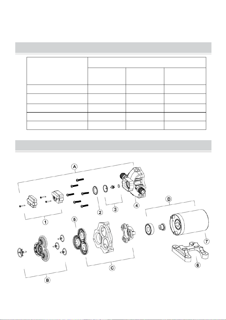
- 6 -
voor de slechte prestaties van de pomp. Voer onderhoud uit en winterklaar de
pomp op de juiste momenten, vooral voor en na een periode van opslag.
ACCESSORIES
1 thema
Hoeveelheid
NMDP33-
G18-60-12
NMDP33-
G30-50-12
NMDP33-
G35-50-12
Handmatig
1
1
1
Slangadapter
X
2
2
Filter
X
1
1
Zeshoekige bout
X
1
1
Afdichtingstape
X
1
1
EXPLODED VIEWS
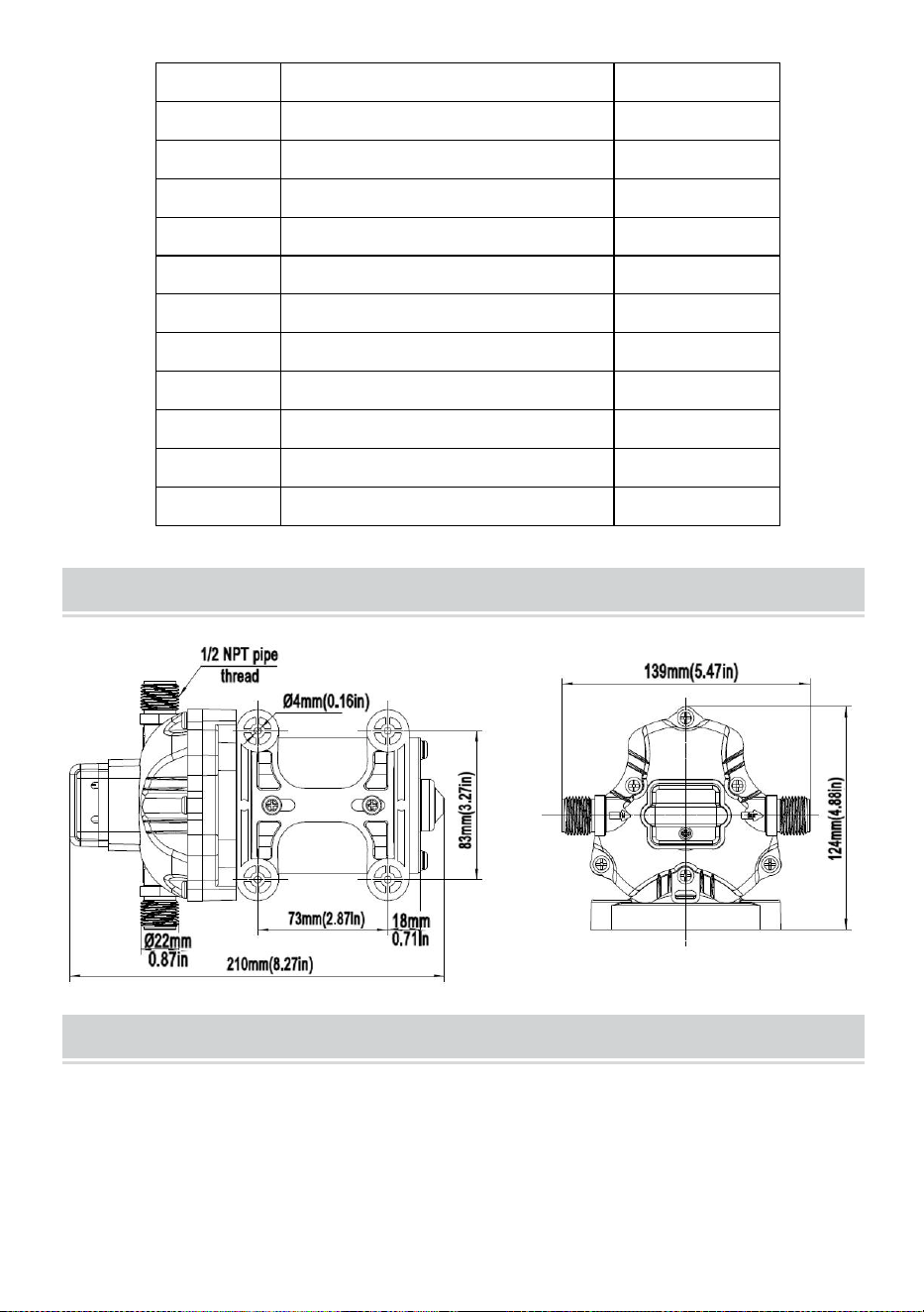
- 7 -
SLEUTEL
Beschrijving
Hoeveelheid
A
Pompkop montage
1
B
Klepmontage
1
C
Membraan assemblage
1
D
Motormontage
1
1
Drukschakelaar
1
2
Membraan van drukschakelaar
1
3
Ventiel kern
1
4
Pompkop
1
5
Diafragma
1
6
Rubberen voet
1
7
Motor
1
PRODUCT SIZE
TROUBLESHOOTING
PULSERENDE STROOM - POMPCYCLI AAN EN UIT
·Controleer de leidingen op knikken.
·De leidingen of fittingen zijn mogelijk te klein.
·Maak kranen en filters schoon.
·Controleer of de fitting goed vastzit en er geen lucht lekt.

- 8 -
NIET AANVULLEN MAAR MOTOR WERKT - GEEN
POMPAFVOER
·Beperkte inlaat- of uitlaatleiding.
·Luchtlek in de inlaatleiding.
·Doorboord pompmembraan
·De initiële stroomtoevoer is niet voldoende om de motor voldoende te starten.
·Er hoopt zich vuil op in de kleppen.
·Scheur in de pompbehuizing.
MOTOR GAAT NIET AAN
· Losse of onjuiste bedrading.
· Er staat geen stroom op het pompcircuit.
· Doorgebrande zekering.
· Defecte drukschakelaar.
· Defecte motor.
POMP GAAT NIET UIT NADAT ALLE ARMATUREN GESLOTEN
ZIJN
· Doorboord middenrif.
· Lekkage in de afvoerleiding.
· Defecte drukschakelaar.
· Onvoldoende spanning.
· Verstopte kleppen in de pompkop.
LAGE STROOM EN DRUK
· Luchtlek bij de inlaat van de pomp.
· Ophoping van vuil in de pomp of leidingen.
· Versleten pomplager (mogelijk gepaard gaand met hard geluid).
· Doorboord middenrif.
· Defecte motor.
LUIDRUCHTIG
·Controleer of de montagevoetjes niet te strak zijn aangedraaid.
· Is het montageoppervlak flexibel? Als dat zo is, kan het zijn dat er ruis
ontstaat.
·Controleer op losse koppen/schroeven.
· Als de pomp is aangesloten met een stijve buis, kan deze gemakkelijker
geluid overbrengen.
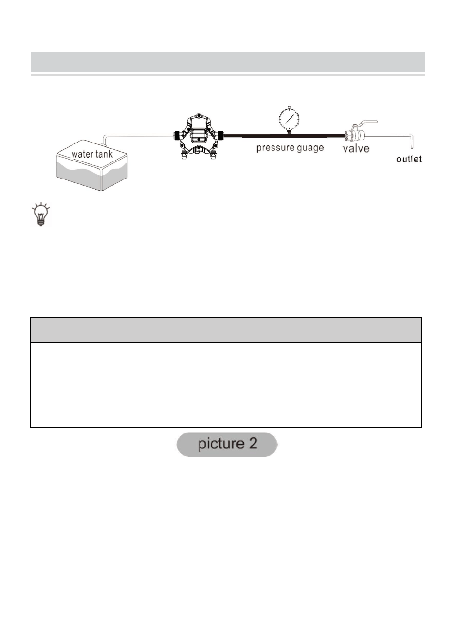
- 9 -
INSTALL THE PUMP AS THE PICTURE 1
T I P: Het bereik van de drukregeling is beperkt. Bedien het apparaat
onder begeleiding van professionele technici, anders werkt het apparaat
mogelijk niet normaal.
DE UITSCHAKELDRUK VAN DE POMP AFSTELLEN:
Stap 1: Verwijder het deksel van de drukschakelaar (nr. 1)
Stap 2: Stel de drukregelschroef (serienummer 2) van de drukschakelaar
nauwkeurig af met een 2 mm sleutel. Als u de druk wilt verhogen, draait u deze
met de klok mee, als u de druk wilt verlagen, draait u deze tegen de klok in.
Stap 3: Plaats de afdekking van de drukschakelaar (nr. 1)
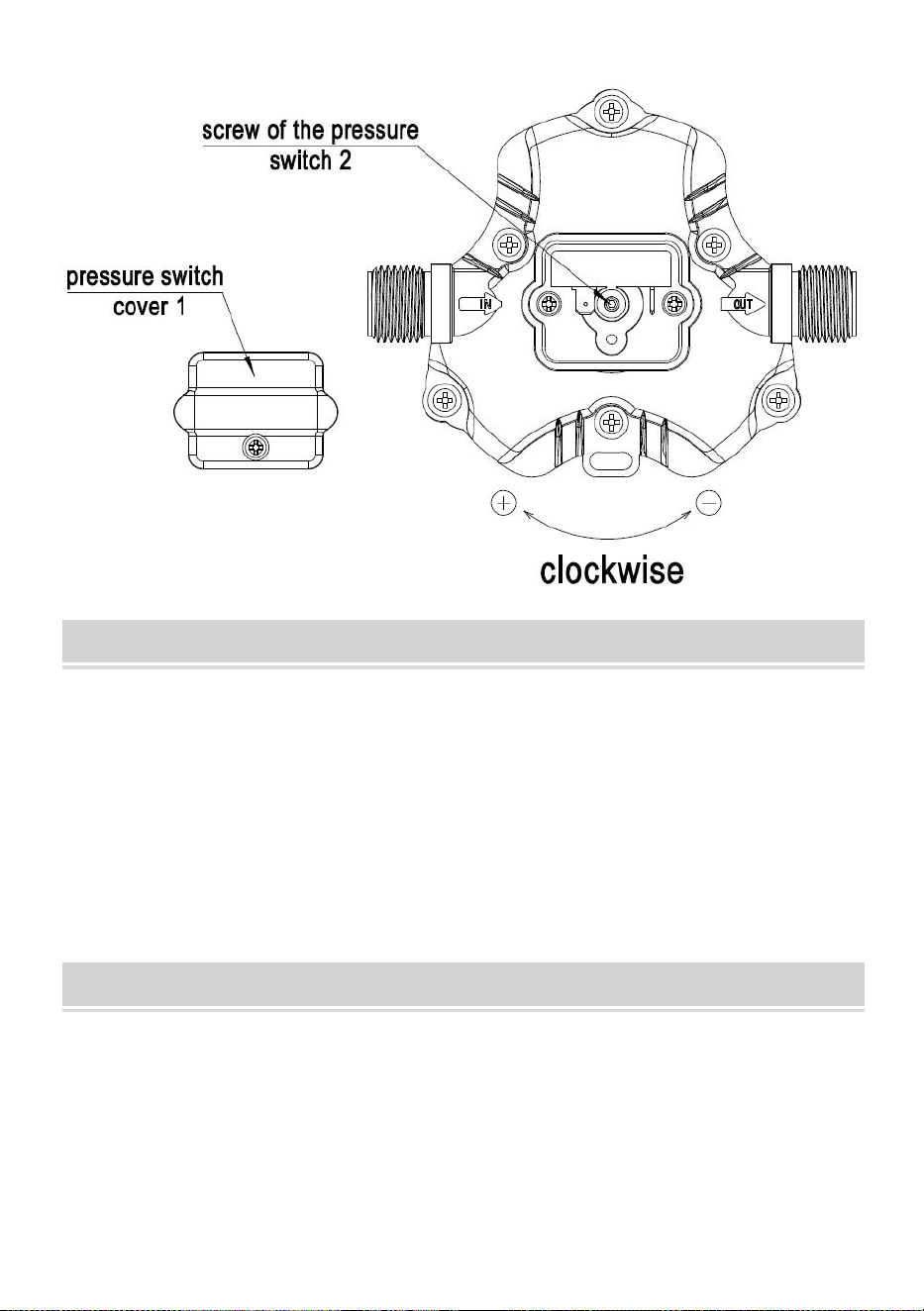
- 10 -
ABOUT THE BYPASS
Raadpleeg een professionele technicus als de bypass moet worden
vervangen. aanpassing. Een onjuiste afstelling van de bypass kan de
pomp.
De bypass is vooraf ingesteld voor een optimale werking van de pomp . Als
uw toepassing vraagt om een andere instelling voor de bypass, u kunt
verander het zelf. Draai de schroef voorzichtig vast om te vergroten of te
versoepelen de schroef om de minimale werkdruk van de omzeilen.
CAUTION
Volg de gebruiksaanwijzing om het product te installeren. handelingen die
buiten de in deze handleiding aanbevolen handelingen vallen, kunnen
leiden tot: schade aan de pomp.
*Er worden zonder voorafgaande kennisgeving kleine wijzigingen
aangebracht in de nummers in de gebruikershandleiding.

- 11 -


- 13 -
Teknisk Support och e-garanticertifikat
www.vevor.com/support
12 VOLT DRICKSVATTENPUMP
MODELL: NMDP33-G18-60-12 /
NMDP33-G30-50-12 / NMDP33-G35-50-12
We continue to be committed to provide you tools with competitive price.
"Save Half", "Half Price" or any other similar expressions used by us only represents an
estimate of savings you might benefit from buying certain tools with us compared to the major
top brands and does not necessarily mean to cover all categories of tools offered by us. You
are kindly reminded to verify carefully when you are placing an order with us if you are
actually saving half in comparison with the top major brands.

- 1 -
MODELL: NMDP33-G18-60-12 / NMDP33-G30-50-12 /
NMDP33-G35-50-12
Have product questions? Need technical support? Please feel free to
contact us:
Technical Support and E-Warranty Certificate
www.vevor.com/support
NEED HELP? CONTACT US!
12 VOLT POTABLE
WATER PUMP
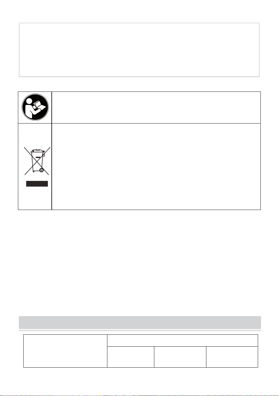
- 2 -
This is the original instruction, please read all manual instructions
carefully before operating. VEVOR reserves a clear interpretation of our
user manual. The appearance of the product shall be subject to the
product you received. Please forgive us that we won't inform you again if
there are any technology or software updates on our product.
Varning- För att minska risken för skada måste användaren läsa
bruksanvisningen noggrant.
KORREKT AVFALLSHANTERING
Denna produkt omfattas av bestämmelserna i det europeiska
direktivet 2012/19/EU. Symbolen som visar en soptunna korsad
anger att produkten kräver separat sophämtning i EU. Detta gäller för
produkten och alla tillbehör märkta med denna symbol. Produkter
märkta som sådana får inte slängas tillsammans med vanligt
hushållsavfall, utan måste lämnas till en insamlingsplats för
återvinning av elektriska och elektroniska apparater.
En ekonomisk arbetshäst, 33-serien är konstruerad för flexibilitet.
3-kammarserien är vår Heavy-Duty vattenpump. I t ger vattenflödet med hög
volym med minskad pumpcykling, tack vare det stora trekammarmembranet.
Med omkopplare på begäran. 33-serien finns i tre storlekar, 1,8GPM/60psi,
3,0GPM/50psi och 3,5GPM/50psi, uppfyller dina speciella krav med positiv
förutsägbar prestanda. 33-serien kan minska snabb cykling och tillåta vatten
att strömma tillbaka från utloppssidan till pumpens inloppssida. Vi erbjuder
även en mängd olika kopplingar och filter som är lätta att ansluta.
PRODUCT SPECICATIONS
Egendom
Specifikationer
NMDP33-
G18-60-12
NMDP33-
G30-50-12
NMDP33-
G35-50-12

- 3 -
Märkspänning
DC 12V
DC 12V
DC 12V
Nominellt tryck
60 PSI
50 PSI
50 PSI
Kammarens nummer
3 st
3 st
3 st
Max. Flöde
1,8 GPM
3,0 GPM
3,5 GPM
Inlopps-/utloppsdiameter
1/2" MNPT
1/2" MNPT
1/2" MNPT
En otrolig funktionslista, högkvalitativa komponenter plus fantastisk prestanda.
Trekammarkonstruktionen med hög volym, driven av en kraftig motor
producerar flödeshastigheter på 1,8GPM/3,0GPM/3,5 GPM, som kan
självsugande upp till 6 vertikalfot och kan köras torrt, vilket gör den till ett pris-
prestationsledare. Denna pump erbjuder även en mängd olika kopplingar och
filter som är lätta att ansluta.
FEATURES
·3-kammars membranpump
· Kontinuerlig tjänst
· Industriell - standard monteringsmönster n
· Torrkörningsförmåga för normal arbetsbelastning
·Automatisk: styrs av tryckvakt
·Självsugande
· Tyst drift
·Antändningsskyddad
APPLICATIONS
· Yacht/RV/husvagn tryckvattensystem
· Sprutarmatur (fordonsmonterade sprutor, elektriska sprutor)
· Rengöringsmaskiner Luftfuktare vattenrening, medicinsk apparatur
· Mat dryck fyllning & vätskeöverföring
· Solvattensystem
· Alla andra trycksättningssystem

- 4 -
INSTALLATION
Material
1.membranpump med tillhörande tillbehör
2. (minst) bitar av flexibla, förstärkta slangrör, med kollapsstyrka på två gånger
inloppets kollapstryck (slangen måste vara minst 1/2"D)
3.slangklämmor och skruvar i rostfritt stål
4.skruvar för att fästa pumpen på monteringsytan
1 strömbrytare
1 säkring
1 skruvmejsel
1 starkt skärredskap för slang (om så önskas) Teflontejp eller tätningsmedel
Inställning
1. Pumpen kan monteras i valfritt läge. Om pumphuvudet monteras vertikalt
ska det vara i nedsänkt läge för att undvika läckage in i motorhuset i händelse
av fel.
2. Säkra fötterna, men tryck inte ihop dem. För hårt åtdragning av
fästskruvarna kan minska deras förmåga att avleda buller och vibrationer.
3. Inlopps- och utloppsslangarna måste vara 1/2" (13 mm) I D förstärkta
slangar. Diametern på grenarna och enskilda matningsledningar från utloppet
bör inte vara mindre än 3/8" (10 mm).
4. Pumla systemet med högtryck (2 x pumpklassning), flätad, flexibel slang för
att minimera vibrationer/buller.
5. Applicera inte inloppstryck som överstiger 30psi. Försök i allmänhet undvika
eventuellt inloppstryck helt.
6. Undvik veck eller beslag som kan orsaka alltför stora begränsningar.
7. Sil ska fästas på inloppssidan.
8. Beslagen måste säkras för att undvika läckage
9. Använd klämmor i båda ändarna av slangen för att förhindra att luft läcker in
i vattenledningen.
10. Om backventilen är installerad i rörsystemet måste den ha ett spricktryck
på högst 2 psi.

- 5 -
11. Om du applicerar en tätningsmedel eller VVS-tejp, var försiktig så att du
inte över dra åt, eftersom de kan sugas in.
12. Denna pump ska kopplas till sin egen dedikerade krets. Anslut den positiva
ledningen (röd) till den positiva polen på ditt batteri och den negativa ledningen
(svart) till den negativa polen på ditt batteri.
13. Installera en strömbrytare på en lättillgänglig plats för att styra elektriciteten
till pumpen. Stäng av pumpen när den inte används under längre perioder eller
när tanken är tom.
14. Den elektriska kretsen ska skyddas med en överströmsskyddsanordning
(säkring) i plusledningen. Denna pump kräver en 15 amp säkring.
15. Pumpkretsen bör inte inkludera några andra elektriska belastningar.
16. Eftersom vattentillförselpumpen inte är nödvändig, hänvisa till
ledningsschemat under den elektriska informationen. Se till att ha rätt
trådstorlek för längden på tråden du använder.
17. Kontrollera spänningen på pumpmotorn efter installationen. Spänningen
bör kontrolleras när pumpen är i drift. Full spänning måste vara tillgänglig vid
pumpmotorn ibland.
Anteckningar
1. Flexibel dricksvattenslang eller PEX-slang rekommenderas istället för stela
rör vid pumpen. Om du väljer att använda styva rörledningar, tillhandahåll en
kort slanglängd mellan röret och pumpen för att undvika buller och vibrationer.
2. Det gör vi rekommenderar inte användning av metallbeslag. Använd de
medföljande plastbeslagen om möjligt.
3. Justera inte bypass personligen utan hjälp av en tekniker.
4. Brist på desinficering och underhåll är en av huvudorsakerna till pumpens
underprestanda. Vänligen utför underhåll och vinterställ pumpen vid lämpliga
tidpunkter, särskilt före och efter en period av förvaring.
ACCESSORIES
1 tema
Kvantitet
NMDP33-
NMDP33-
NMDP33-
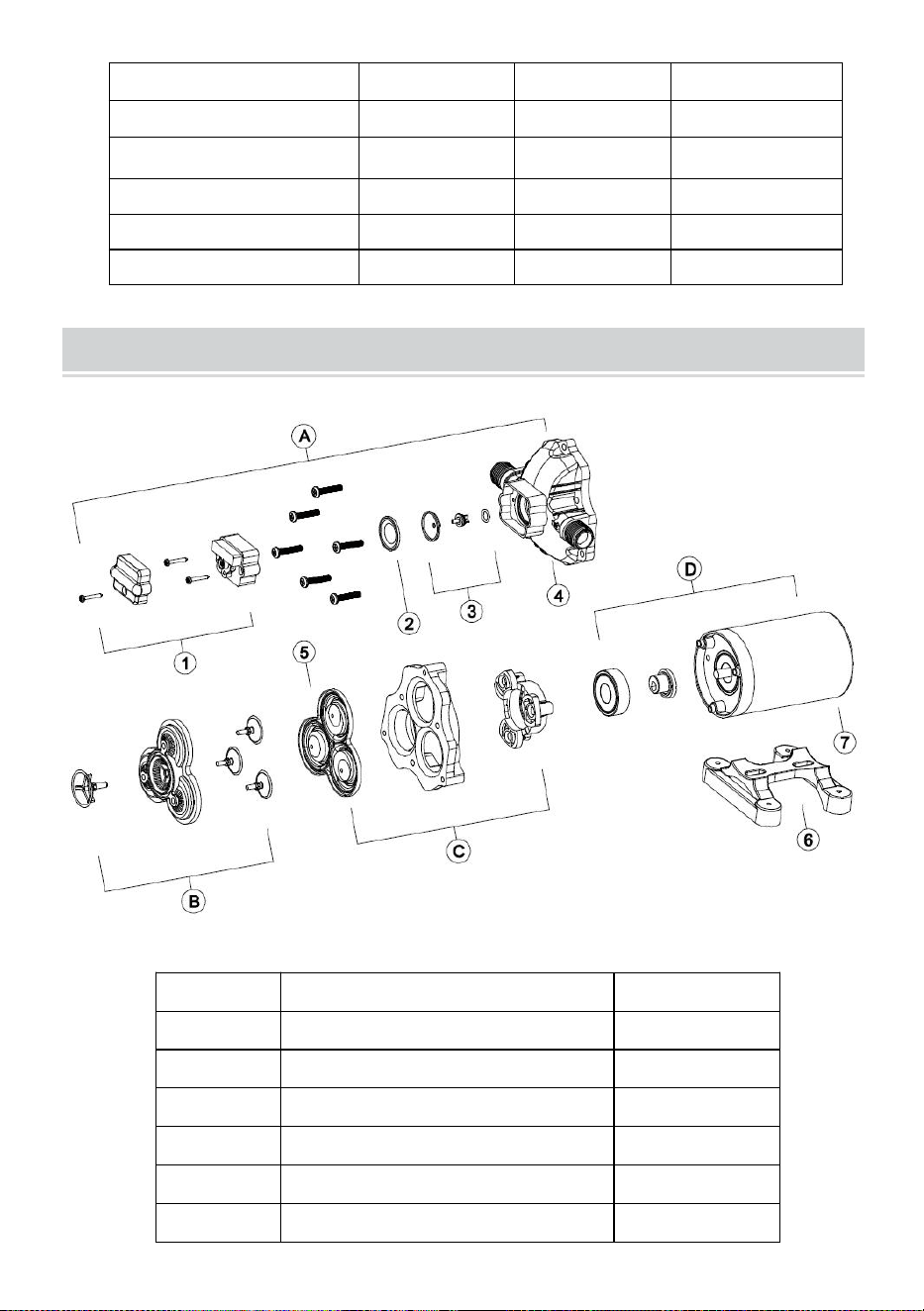
- 6 -
G18-60-12
G30-50-12
G35-50-12
M anual
1
1
1
Slangadapter
x
2
2
Filtrera
x
1
1
Sexkantsbult
x
1
1
Tätningstejp
x
1
1
EXPLODED VIEWS
NYCKEL
Beskrivning
Kvantitet
A
Pumphuvudenhet
1
B
Ventilmontering
1
C
Membranmontering
1
D
Motorenhet
1
1
Tryckbrytare
1
2
Tryckbrytarens membran
1
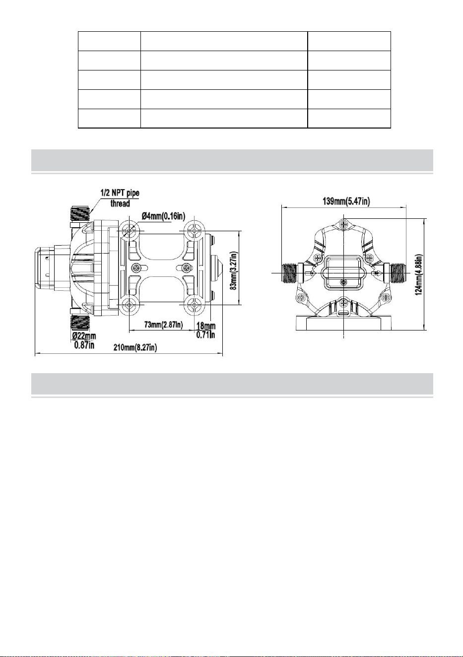
- 7 -
3
Ventilkärna
1
4
Pumphuvud
1
5
Membran
1
6
Gummifot
1
7
Motor
1
PRODUCT SIZE
TROUBLESHOOTING
PULSERANDE FLÖDE- PUMP CYKLAR PÅ OCH AV
·Kontrollera linjer för veck.
·VVS-ledningar eller rördelar kan vara för små.
·Rengör kranar och filter.
·Kontrollera tätheten för luftläckor.
UNDERLÅTE ATT FYLLA MEN MOTORN FUNGERAR-INGEN
PUMPUTLOPP
·Begränsad intags- eller utloppsledning.
·Luftläckage i inloppsledningen.
·Punkterat pumpmembran
· Den initiala förstärkaren räcker inte för att starta motorn tillräckligt.
·Smuts täpper till i ventilerna.

- 8 -
·Spricka i pumphuset.
MOTORN SLÅR INTE PÅ
· Lösa eller felaktiga ledningar.
· Pumpkretsen har ingen ström.
· Trasig säkring.
· Misslyckad tryckvakt.
· Defekt motor.
PUMPEN ÄR INTE AVSTÄNGD EFTER ALLA FIXTUTER ÄR
STÄNGDA
· Punkterat diafragma.
· Utloppsledningsläcka.
· Defekt tryckvakt.
· Otillräcklig spänning.
· Tilltäppta ventiler i pumphuvudet.
LÅGT FLÖDE OCH TRYCK
· Luftläckage vid pumpintaget.
· Ansamling av skräp inuti pumpen eller rörledningarna.
· Slitet pumplager (eventuellt tillsammans med högt ljud).
· Punkterat diafragma.
· Defekt motor.
BULLRIG
·Kontrollera om monteringsfötterna är för hårt hoptryckta.
· Är monteringsytan flexibel? I så fall kan det lägga till brus.
·Kontrollera för lösa huvud/skruvar.
· Om pumpen är försedd med ett styvt rör, kan den överföra ljud lättare.
INSTALL THE PUMP AS THE PICTURE 1
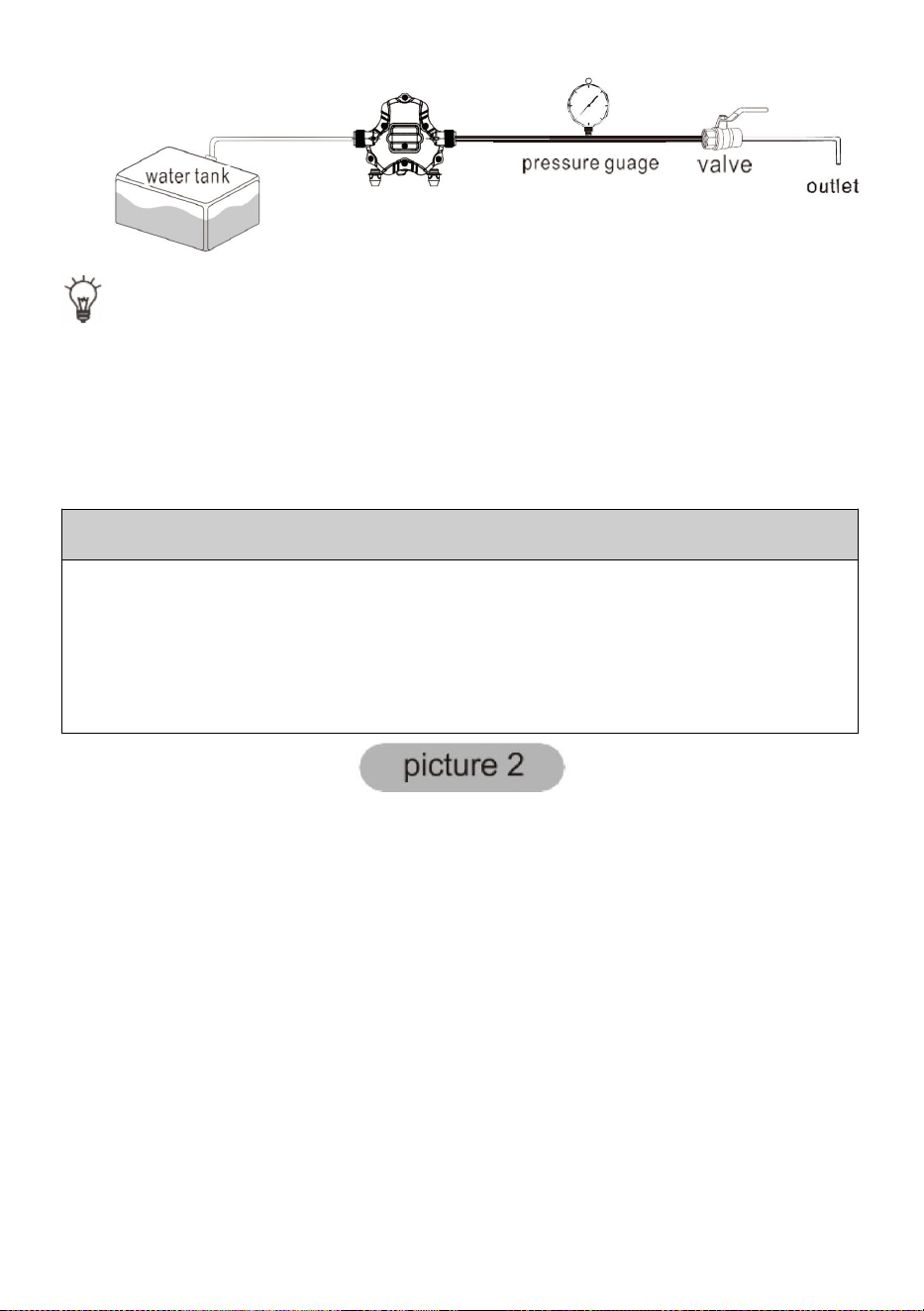
- 9 -
T I P: Omfånget för tryckreglering är begränsat. Vänligen kör under
ledning av professionella tekniker, annars kanske maskinen inte fungerar
normalt.
JUSTERING AV PUMPENS AVSTÄNGNINGSTRYCK:
Steg 1: Ta bort locket till tryckvakten (nr 1)
Steg 2: Finjustera tryckjusteringsskruven (serienummer 2) på tryckbrytaren med
en 2 mm skiftnyckel, om du vill öka trycket, vrid den medurs, om du vill minska
trycket, vrid den moturs.
Steg 3: Installera tryckvaktslocket (nr 1)
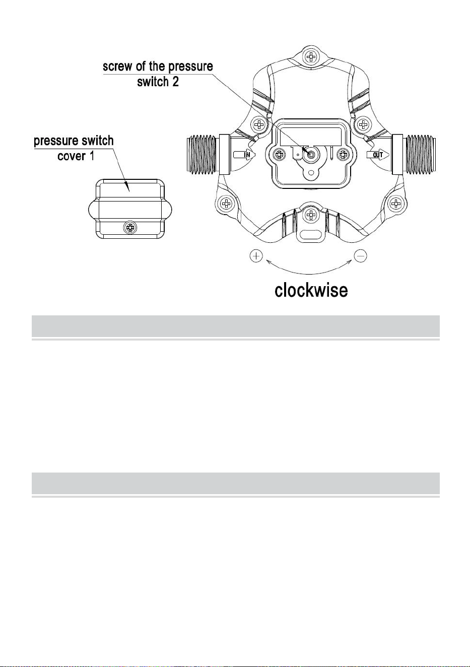
- 10 -
ABOUT THE BYPASS
Kontakta en professionell tekniker om bypass behöver justering. En korrekt
justering av bypass kan skada pump.
Bypass är förinställt för optimal drift av pumpen . Om din applikationen
kräver en annan inställning för bypass, kan du ändra det själv. Dra åt
skruven försiktigt för att öka eller lossa skruven för att minska det lägsta
drifttrycket på gå förbi.
CAUTION
Vänligen följ bruksanvisningen för att installera produkten. Några åtgärder
utanför vad som rekommenderas i denna handbok kan medföra skada på
pumpen.
*Det finns några mindre ändringar av siffrorna som ingår i
användarmanualen utan föregående meddelande.

- 11 -