Caution: Read all notes prior to installation
i•
WARNING: TO AVOID FIRE, SHOCK, OR DEATH; TURN
OFF POWER at the circuit breaker or fuse and test that the
power is off before wiring!
h
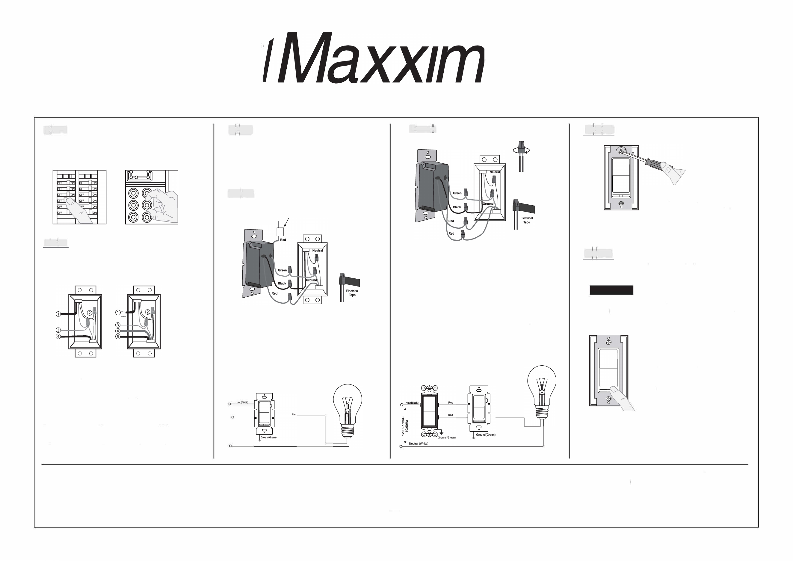
lndentiing your wiring application
(most common):
NOTE: If the wiring in the wall box does not resemble
any of these configurations, consult an electrician.
Single-Pole
1. Line (Hot)
2. Neutral
3. Ground
4.Load
3-Way
1. Line or Load Common
(See impoaint instructions below)
2. Neutral
3. Ground
4. First Traveler
5. Second Traveler
IMPORTANT: For 3-way applications, note that one of the screw terminals
from the old switch being removed will usually be a dierent color (Black)
or labeled Common.g that wire with electrical tape and identi ii as the
common (Line or Load) in both the dimmer wall box and the standard
3-way switch wall box. The remaining two wires on the brass or lighter
screw terminals of the old switch are the travelers.
•
,,,,,,,,
a
®
M
EW-DM650, MEW-DM650A, MEW-DM650B, MEW-DM650V, MEW-DM650G
and
MEW-DM65
1
INSTALLION INSTRUCTIONS
i11 p - -
reparmg wires:
• Pull o the pre-cut insulation from the Dimmer leads.
• Make sure that the ends of the wires from the wall
box are straight (cut if necessary).
HUi
Single-Pole wiring application:
This wire is used in 3-Way installations only,
For single pole installations, do not remove this
insulating label.
t
Insert wires
straight then
twist clockwise
Connect wires per WIRING DIAGRAM A as follows:
Screw wire nuts on clockwise making sure no bare conductors show
below the wire connectors. Secure each connector with electrical tape.
• Green dimmer Ground lead to Green or bare copper wire in wall box.
• Black dimmer lead to Line Hot wall box wire.
• Red dimmer lead without insulating label to Load wall box wire
• Remaining Red dimmer lead should have Red insulation label aixed.
NOTE: If the insulating label is not aixed to Red lead, use
a small wire nut or electrical tape to cap o.
i
r�
7!
��
l Nel ite)
ij=j
3-way wiring application:
Inse wires
straight then
twist clocise
Connect wires per WIRING DIAGRAM B as follows:
Screw wire nuts on clockwise making sure no bare conductors show
below the wire connectors. Secure each connector with electrical tape.
NOTE: Dimmer can be installed on either the Load or Line side
• Green dimmer Ground lead to Green or bare copper wire in wall box.
• Black dimmer lead to tagged (common) wall box wire identified in Step 2.
• Remove Red insulating lable from the Red lead.
• First Traveler wall box wire identified in Step 2 to any red dimmer lead.
• Second Traveler wall box wire identified in step 2 to the remaining red
dimmer lead.
Black
Dimmer Mounting:
Installation may now be completed by carefully
positioning all the wires to provide room in the
wall box for the dimmer. Mount the dimmer into
the box with supplied mounting screws.
Attach wallplate.
ijj
Restore Power:
Restore power at the circuit breaker or
fuse. Installation is complete.
OPETION
NOTE: If using the dimmer in a 3-way application, the lights will turn
ON at brightness set on the dimmer's slide control lever. The lights
can be controlled from either the dimmer or the switch location.
ON/OFF:
Depress button switch to ON position
- Lights will turn ON
Depress button switch to OFF postion
- Lights will turn OFF
BRIGHTEN & DIM:
Move the slider control lever -
Lights will BRIGHTEN or DIM
Warranty: Maxxima extends a 1 year limited warranty to the original purchaser that the products purchased are free from defects in material and/or workmanship only. The limited warranty is not transferable. This
oer does not constitute in any way a product guarantee and Maxxima does not hereby assume any obligation whatsoever beyond sending a replacement product at no charge during the warranty period.
Maxxima, 125 Cabot Ct., Hauppauge, NY 11788
TEL: 631.434.1200 FAX: 631.434.1457
www.maxximastyle.com
.,,,,,,11 Ma
®
INSLLION INSTRUCTIONS for MEW-DM650 a
n
d MEW-DM65
1
Series 3-Way Slide Dimmer
Important Notes
Please read before installing (COMPLETE INSLLATION INSTRUCTIONS CONTINUED ON THE OTHER SIDE}
1. CAUTION: Use only permanently installed 120V AC fixtures using incandescent or halogen or dimmable LED
or dimmable CFL lamps. avoid overheating and possible damage to other equipment, do not use the control
receptacles, flourescent lighting fixtures or transformer-supplied appliances.
2. Always use appropriate electrical power verification instruments to verify that the power is OFF bere
installing the dimmer
3. Install in accordance with all national and local electric codes.
4. Only use one dimmer in a 3-way circuit.
5. When no "grounding means" exists within the wall box then NEC 2008, Article 404-9 allows a dimmer without a
grounding connection to be installed as a replacement, as long as a plastic, non-combustable wallplate is used.
For this type of installation, cap the green ground wire on the dimmer.
6. For new installations, install a test switch before installing the dimmer.
7. Protect the dimmer from dust and dirt when painting or spackling.
8. It is normal for the dimmer to feel warm to the touch durring operation.
9. Clean the dimmer with a so, mp cloth only. Do not use any chemical cleaners.
10. For indoor use only.
11. Mount the dimmer to the wall box using the provided screws. The dimmer must be mounted vertically. See the
stamp on the dimmer for correct positioning.
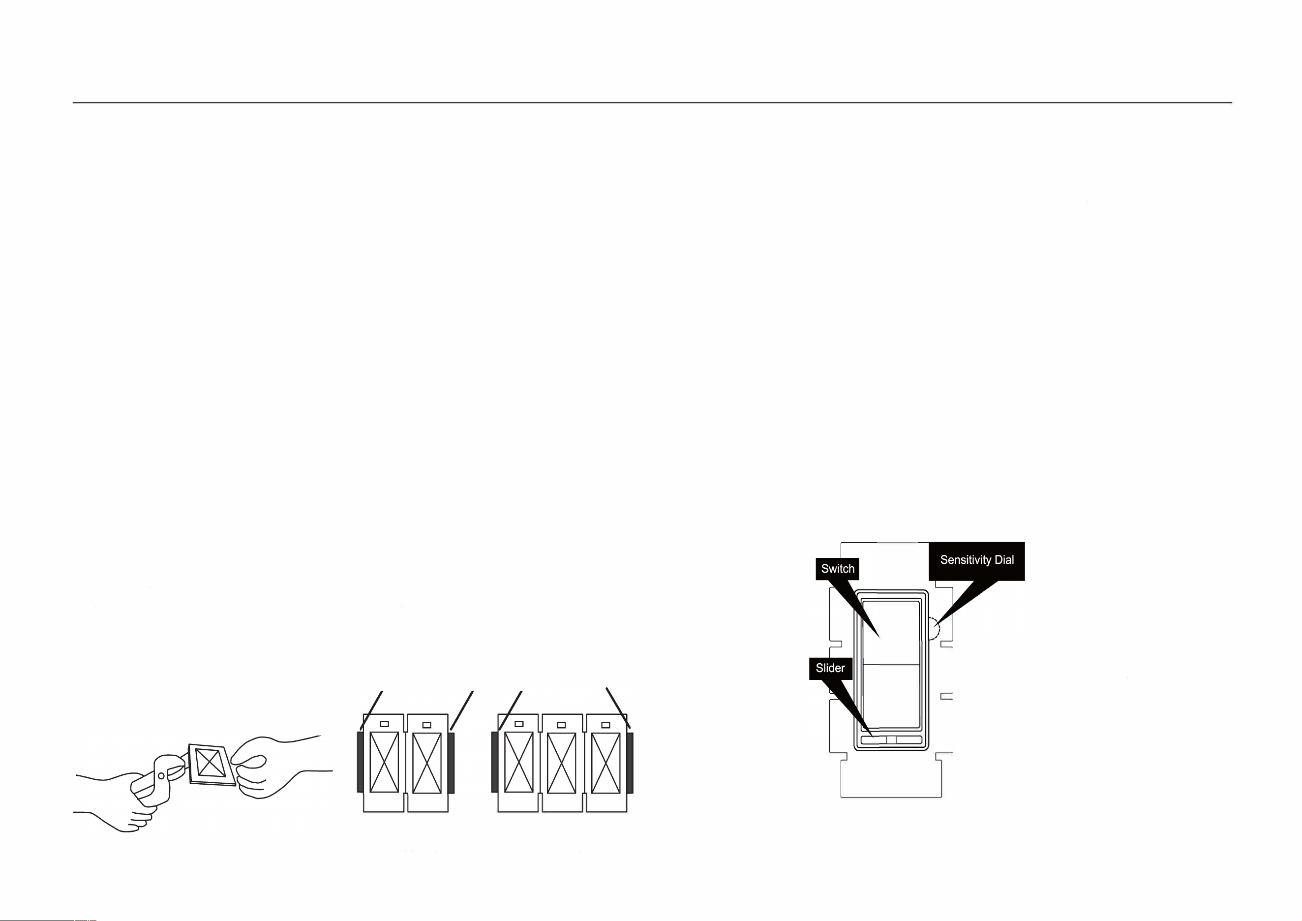
Multigang Installations:
When installing more than one control in the same wall box, it may be
necessary to remove all the inner side sections prior to wiring. Using
pliers, bend each needed side section up and down until it breaks o.
Dimmer Capacity:
600W unmodified
Do Not Remove
Outside Sections
500W if one side is removed
400W if both sides are removed
---------
□
□
Each Contl Has Inside
Seions Removed
□
□ □
Middle Contl Has Two Side
Seions Removed
Dimmer Range Adjustment:
Aer installation (see other side), adjust circuit dimming as follows:
1. Turn on the switch and move the slide dimmer to the lowest setting.
2. Adjust the Sensitivity Dial all the way up (Counter-Clockwise). NOTE: If
the dial stops in either direction, do not continue to turn it.
3. Begin to adjust the Sensitivity Dial down (Clockwise) until the preferred
lowest light level is acheived and the light output is stable for all lamps on
the circuit. If all the lamps on the circuit go out, adjust the sensitivity back
up slightly (Counter-Clockwise).
4. Once the lowest light level is set, test the slide dimmer in the lowest
position by switching the dimmer o and then on by the ON/OFF switch
to veri all the lamps turn on at the lowest level.
5. If all the lamps do not turn back on, repeat steps 1-4, but set the lowest
light level slightly higher than the previous attempt.
6. Once all the lamps are dimming properly, install the faceplate.
0
0
MEW-DM650
Sensitivity Dial
• Rotate Counter-Clockwise
More Bright
•Rotate Clockwise
Less Bright