1 2 3
64 5
9
8
7
*
0
#
Installation Guide
Thank you for purchasing our product. Please read this manual carefully before
installing or operating your device.
Note: Images in this manual are for illustration purposes only. The actual product
may vary due to updates or enhancements.
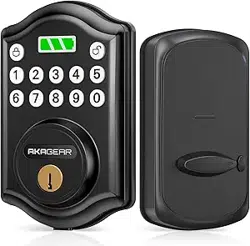
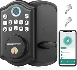
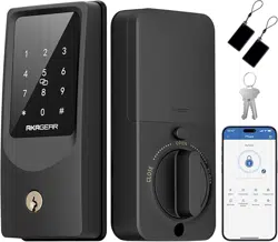
Smart Lock T02 mini
A C
E F G H
I
D
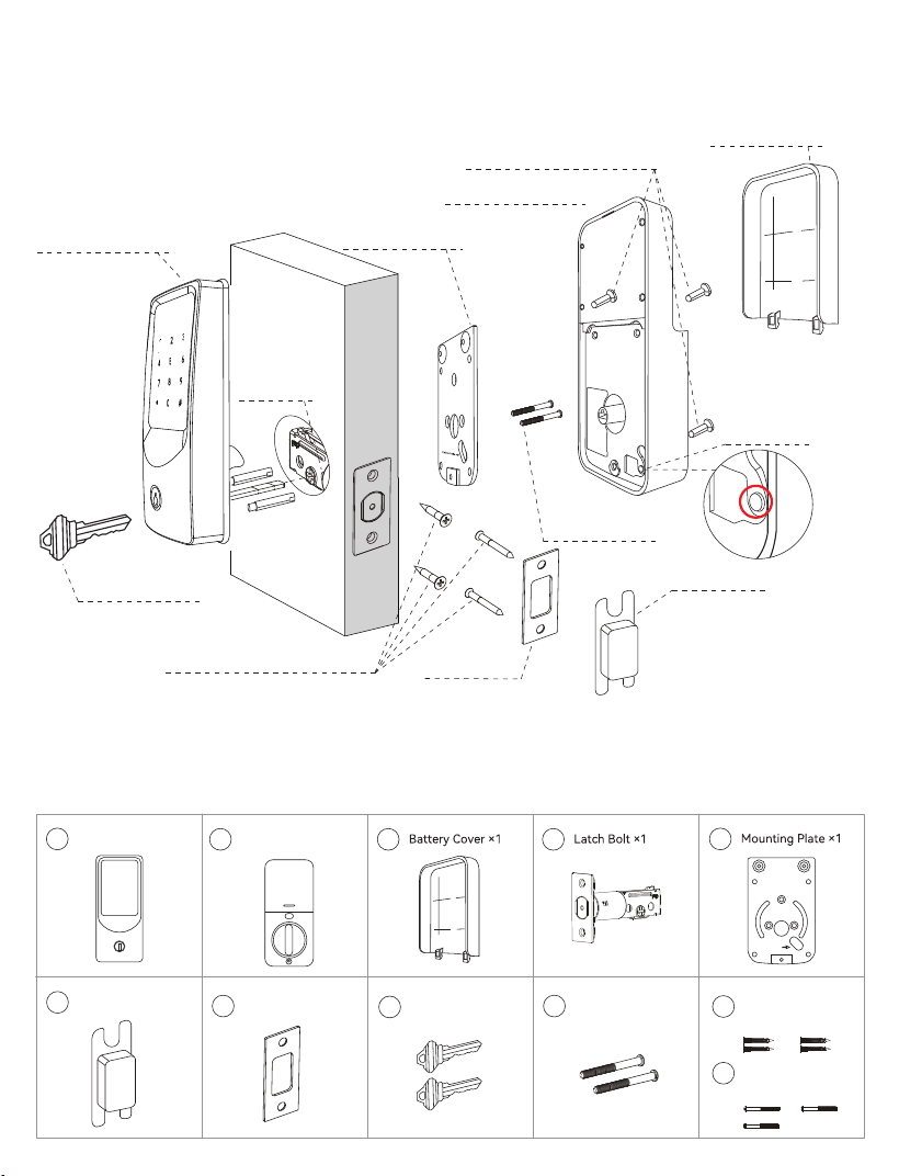
Parts List
Latch and Strike Screws (J)
Strike Plate (G)
Backup Key (H)
Mounting Plate
Screws (I)
Battery Cover (C)
Mounting Plate (E)
Interior Assembly (B)
Exterior Assembly (A)
Latch Bolt (D)
Plastic Box (F)
Interior Assembly Screws (K)
A Exterior Assembly x 1
B
A
B B
A
C
C
B
A
D
C
B
A
E
B
A
F
E
B
A
G
F
E
B
A
H
F
I
B
A
I
Latch and Strike
Screws × 4
B
A
J
Interior Assembly
Screws × 3
B
A
K
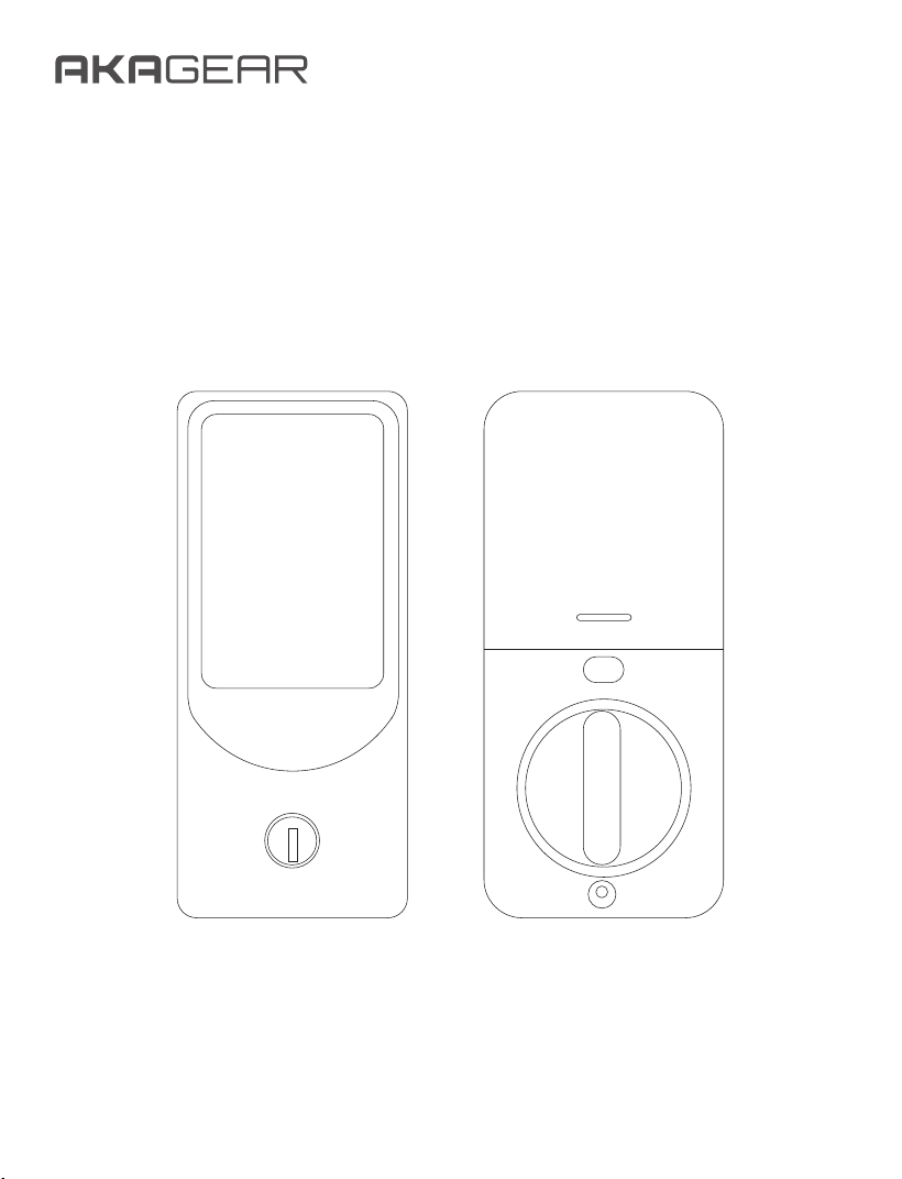
Overview
Reset Button
1
2 3
64 5
9
8
7
*
0
#
Cable hole
Assembly Diagram
Mounting Plate
Screws × 2
Backup Key × 2
Strike Plate × 1
Plastic Box × 1
Interior Assembly × 1
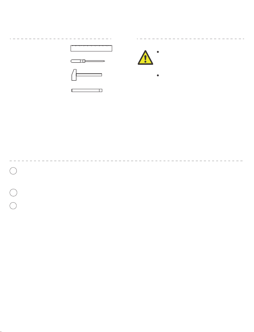
Tools Required:
Do not insert the key into the
cylinder during installation.
Do not insert the batteries
until the lock is fully installed.
Ruler
Philips Screwdriver
Hammer
Chisel
Important Safety Notice:
Before You Begin
Pre-Installation Tips:
Before installing the lock, make sure the door frame is properly aligned with the
door and that there are no obstructions inside the frame.
If you encounter any issues during installation, please contact our customer service
team for assistance—we're here to help!
1
2
3
Ensure the latch is adjusted for horizontal insertion.
Use 8 new, non-rechargeable AA batteries for optimal performance.
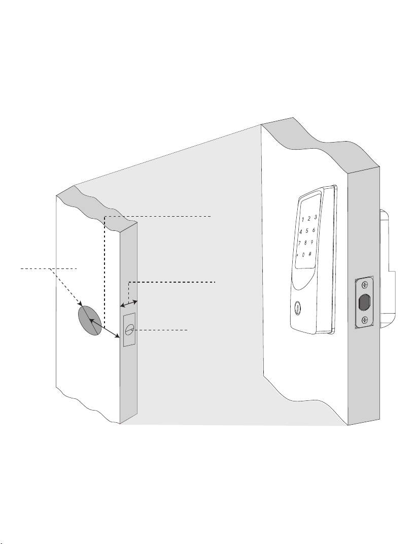
Crossbore:
2-1/8" (54mm)
Backset:
2-3/8" or 2-3/4"
(60mm or 70mm)
Door Thickness
1-3/8" to 2"
(35mm to 50mm)
Latch Hole:
1"(25mm)
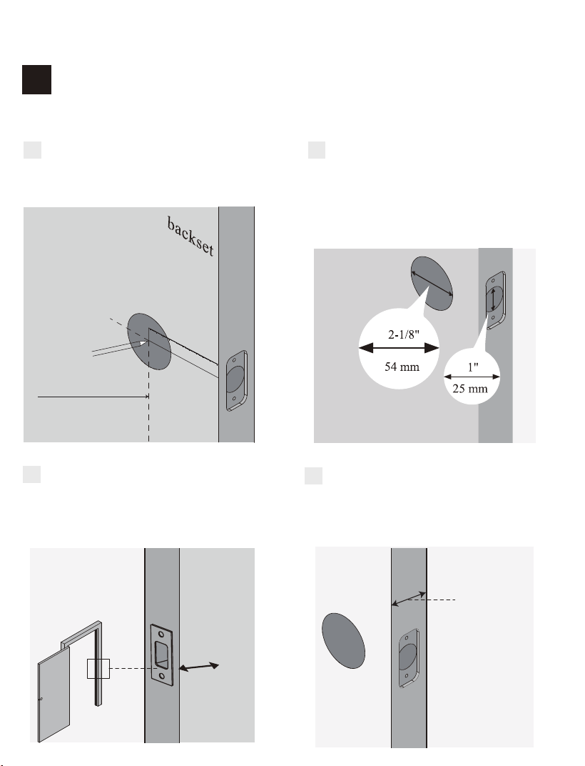
Prepare Your Door
1
STEP
Confirm the hole on the door edge is
1" (25mm).
B
Confirm the hole in the door is 2-1/8"
(54mm).
Confirm the backset is either 2-3/8"
or 2-3/4" (60 or 70mm).
A
Confirm the door thickness is
between 1-3/8" and 2" (35 mm to
50mm).
D
1-3/8" to 2"
(35mm to 50mm)
Ensure the hole in the door frame is
drilled to a minimum depth of 1"
(25mm).
C
1"
25mm
2-3/8"(60mm)
Installation Steps
Confirm Door Dimensions and Compatibility
Install Latch and Strike
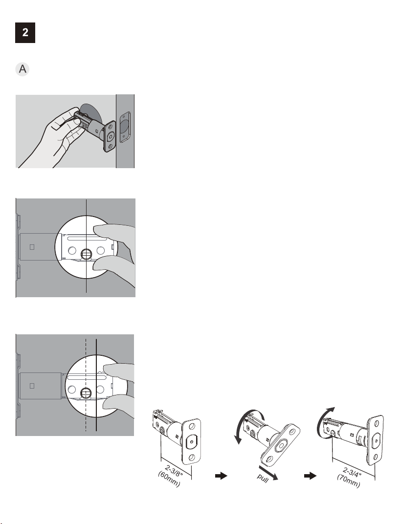
Adjust Latch for Backset
1. Hold the latch against the door edge, ensuring
the latch face is flush.
2. Check whether the slotted hole is centered in
the door hole.
STEP
No adjustment needed.
Proceed to the next step.
If Yes:
The slotted hole is NOT centered.
Rotate and extend the latch as shown to adjust
the length.
If No:
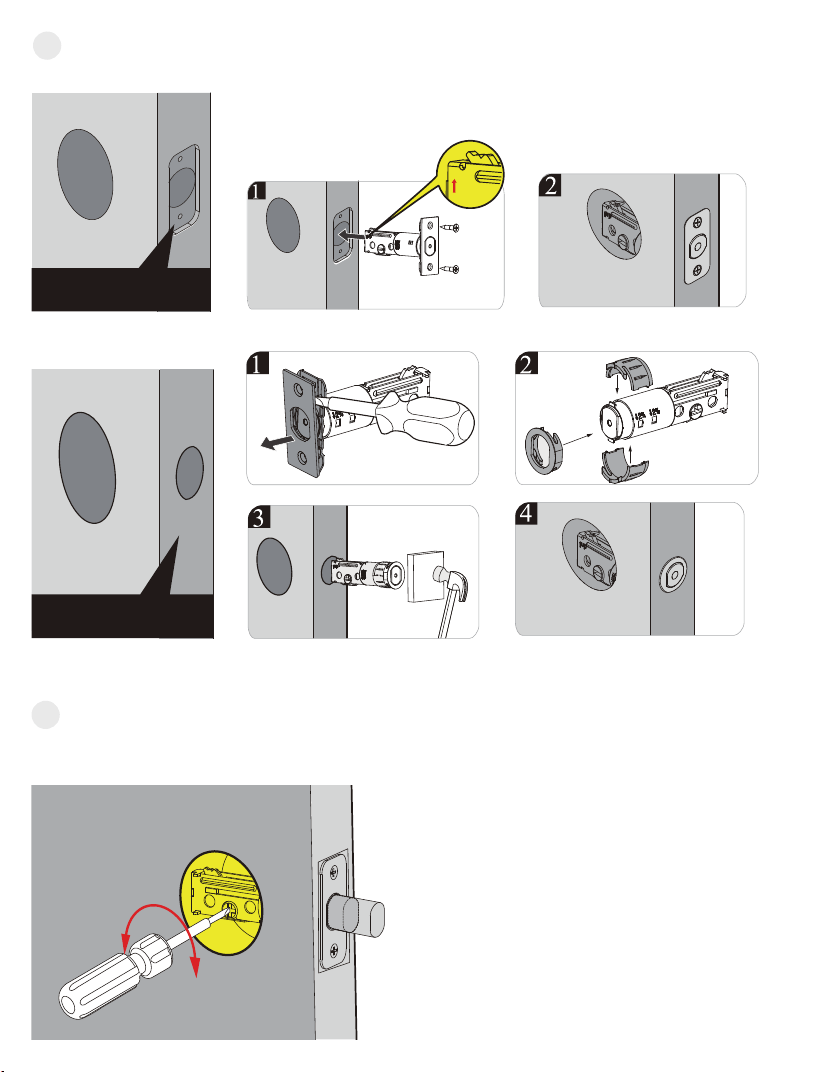
chiseled
Latch and Strike
Screws (J)
B
Install Latch
Drive-In Collar
C Test Latch Operation
up
non-chiseled
Use a screwdriver to turn the latch and confirm the bolt moves smoothly.
Ensure the hole behind the
strike plate is drilled at least 1"
(25mm) deep to allow full bolt
extension.
IMPORTANT:
D
Install Strike Plate on Door Frame.
G
F
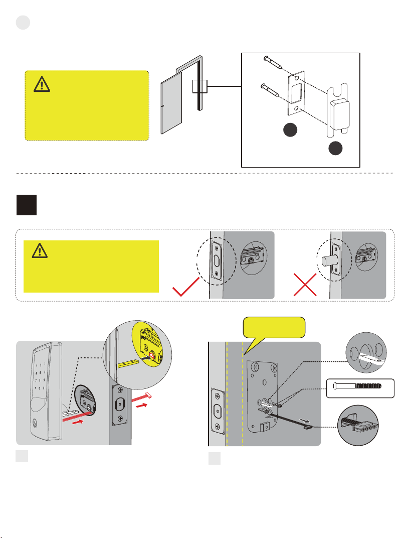
Install Exterior Assembly
3
STEP
Unlocked
Before installation, make sure the
latch is fully retracted (unlocked
position).
IMPORTANT:
Locked
Mounting Plate Screws(I)
Keep parallel to
door edge.
With the latch fully retracted, route
the cable below the latch and insert
the torque blade through the slot.
Torque
Blade
Secure the mounting plate to the door
using the supplied screws. Do not
overtighten screws.
Cable hole
Cable hole
Attach the strike plate to the door frame using the Latch and Strike Screws (J).
Latch and Strike Screws (J)
A
B
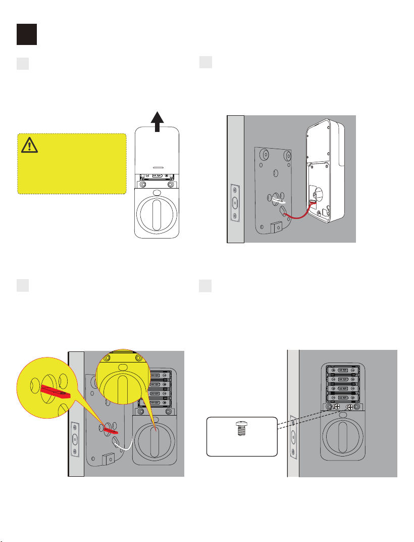
Install Interior Assembly
4
STEP
A
Remove the battery cover by sliding
it in the direction shown in the
illustration.
Do not insert batteries
until installation is fully
completed.
IMPORTANT:
B
Connect the cable by inserting the connec-
tor into the socket. Push firmly until fully
secured.
C
Keep the thumb turn in the vertical
position, then align and install the
interior assembly.
D
Attach the interior assembly to the mounting
plate and tighten the three screws.
Interior Assembly
Screws (K)
C
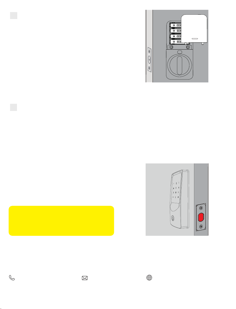
Insert 8 AA batteries and reinstall the battery cover.
E
C
Detect the Door’s Opening Direction
F
Ensure the lock is properly installed, then follow these steps:
1. Keep the lock in the unlocked state.
2. Insert 8 AA batteries.
3. Wait for the voice prompt (within 5 seconds) and a green light flash.
4. Enter a passcode to verify that the deadbolt extends and retracts properly.
Note: Please wait approximately 5 seconds
after powering on to allow the lock to
complete orientation before proceeding with
further setup.
Contact Us
For any inquiries about AkaGear products, please feel free to contact us.
Operating Hours: Mon–Fri 9 a.m.–5 p.m. (EST)
(888) 811-1140 (US) [email protected]
www.akagear.net