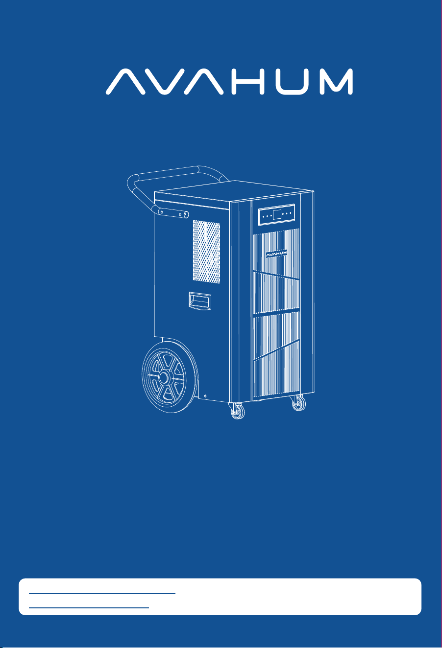
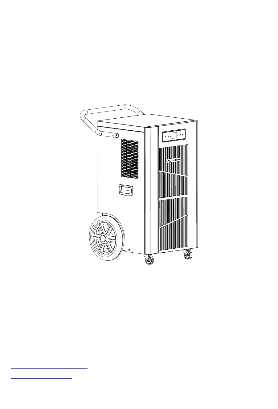
Model:CFT320P
Thank you for your order.
You made our day.
Thanks for your purchase.
If any problems with our dehumidifier, please feel free to contact us.
Please refer to the model on the nameplate of the machine.
Please read the user manual carefully before use and keep it properly.
E-Mail: Support@avahum.com
http: // www.avahum.com
Thank for your purchase.
Warm Tips:
When the machine needs to be moved and when it is not used for a long time,
please use the “Pump” button to force the machine to empty the residual water.
The “Defrost” indicator light indicates that the machine is defrosting, possibly due
to a low ambient temperature.
The “EC” fault code indicates that the machine is malfunctioning.
If you experience any of these problems, please contact us and AVAHUM
Customer Service will assist you.
Support@avahum.com
www.avahum.com
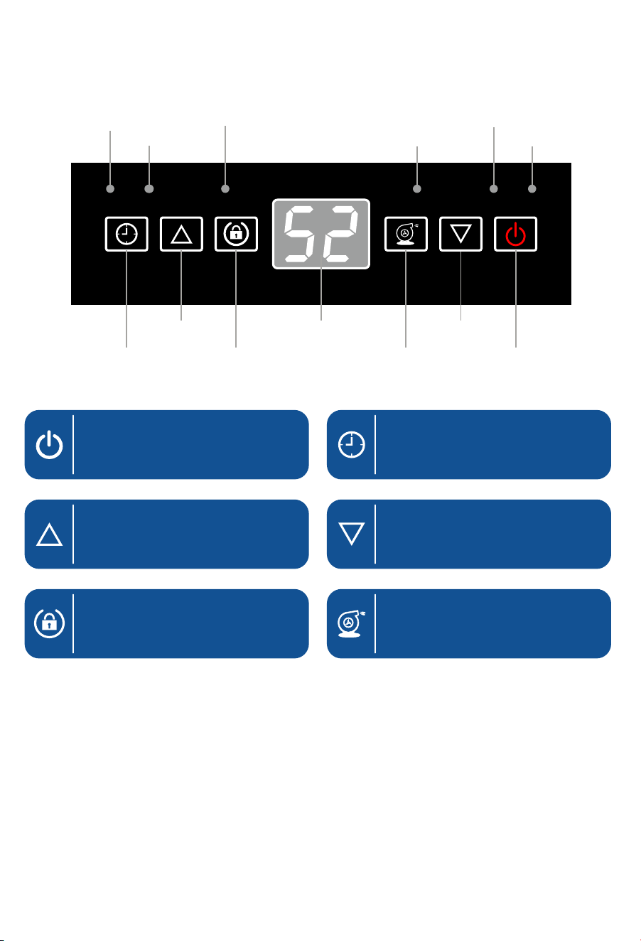
Timer light
Power Key
Up Key(Humidity Set)
To turn the machine on/off.
Adjust the set humidity
upwards.
Timer Key
Used to set the time on the device,
the setting range is 1-24h.
Down Key(Humidity Set)
Adjust the set humidity
downwards.
TIMERPOWERDOWN
UPPUMP
TIMER
FULL
LOCK
LOCK
POWER
PUMP
DEFROST
Up key Display window
Timer key
Defrosting light
Power light
Full light
Down key
Power key
Lock light
Pump light
Lock key Pump key
Lock Key(Long Press 3S)
For activation and deaction of
the child lock function.
Pump Key
Forced pump drainage to drain
water left in the machine.
(Used when moving
and storing the machine)
BEFORE FIRST USE:
Please leave the dehumidifier standing upright and outside the box for
24 HOURS before plugging it in.
The dehumidifiers may have been tilted or placed upside down during
shipping. Leave the dehumidifier to stand upright for 24 hours so the
oil in the compressor can settle from the move, not doing so can affect
the performance or lifespan of the dehumidifier.

Warning For Using R32 Refrigerant .............................................. 1
Parts Identification ......................................................................... 15
Operation Instructions .................................................................. 16
● Install the handle .......................................................................... 16
● Position your dehumidifier ............................................................ 17
● Setting up the drainage system .................................................... 17
● Plug in electrical cord ................................................................... 18
● Understand the control panel ....................................................... 19
Maintenance ................................................................................... 24
● Cleaning the dehumidifier ............................................................. 24
● Cleaning the air filter ..................................................................... 24
● When not using dehumidifier for long periods of time ................... 25
Trouble Shooting Guide ................................................................ 26
● Trouble shooting chart ................................................................... 26
Specifications ................................................................................. 28
Parts List ......................................................................................... 29
Limited Warranty ............................................................................ 30
CONTENTS

P.01
Transportation, marking and storage for units that
employ flammable refrigerants
General
The following information is provided for units that employ FLAMMABLE
REFRIGERANTS.
Transport of equipment containing flammable refrigerants
Attention is drawn to the fact that additional transportation regulations may exist
with respect to equipment containing flammable gas. The maximum number of
pieces of equipment or the configuration of the equipment permitted to be
transported together will be determined by the applicable transport regulations.
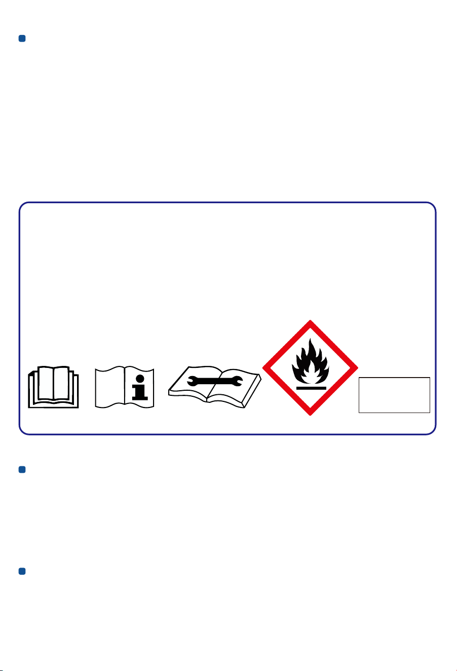
Marking of equipment using signs
Signs for similar appliances used in a work area are generally addressed by local
regulations and give the minimum requirements for the provision of safety and/or
health signs for a work location. All required signs are to be maintained and
employers should ensure that employeesreceive suitable and sufficient instruction
and training on the meaning of appropriate safety signs and the actions that need
to be taken in connection with these signs.
The effectiveness of signs should not be diminished by too many signs being
placed together. Any pictograms used should be as simple as possible and contain
only essential details.
Disposal of equipment using flammable refrigerants
See national regulations.
Storage of equipment/appliances
The storage of the appliance should be in accordance with the applicable
regulations or instructions, whichever is more stringent.
WARNING for Using R32 Refrigerant
Storage of packed (unsold) equipment
Storage package protection should be constructed in such a way that mechanical
damage to the equipment inside the package will not cause a leak of the
REFRIGERANT CHARGE.
The maximum number of pieces of equipment permitted to be stored together will
be determined by local regulations.
Requirements for operation, service and installation manuals of
appliances using flammable refrigerants
Qualification of workers
The manual shall contain specific information about the required qualification of
the working personnel for maintenance, service and repair operations. Every
working procedure that affects safety means shall only be carried out by
competent persons.
Examples for such working procedures are:
breaking into the refrigerating circuit;•
opening of sealed components;•
Refrigerant
Safety Group
A2L
WARNING
Do not use means to accelerate the defrosting process or to clean, other than
those recommended by the manufacturer.
The appliance shall be stored in a room without continuously operating ignition
sources (for example: open flames, an operating gas appliance or an
operating electric heater. Do not pierce or burn.Be aware that refrigerants may
not contain an odour.
P.02

lCompetence of service personne
General
Information of procedures additional to usual information for refrigerating appliance
installation, repair, maintenance and decommission procedures is required when
an appliance with FLAMMABLE REFRIGERANT is affected.
The training of these procedures is carried out by national training organisations or
manufacturers that are accredited to teach the relevant national competency
standards that may be set in legislation.
The achieved competence should be documented by a certificate.
Information and training
Ⅰ. The training should include the substance of the following.
Ⅱ. Information about the explosion potential of FLAMMABLE REFRIGERANTS
to show that flammables may be dangerous when handled without care.
Ⅲ. Information about POTENTIAL IGNITION SOURCES, especially those that
are not obvious, such as lighters, light switches, vacuum cleaners, electric
heaters.
Ⅳ. Information about the different safety concepts:
Unventilated-Safety of the appliance does not depend on ventilation of the
•
housing.
Switching off the appliance or opening of the housing has no significant effect
•
on the safety.
Nevertheless, it is possible that leaking refrigerant may accumulate inside the
•
enclosure and flammable atmosphere will be released when the enclosure is
opened.
Ventilated enclosure-Safety of the appliance depends on ventilation of the
•
housing.
Switching off the appliance or opening of the enclosure has a significant effect •
on the safety.
Care should be taken to ensure sufficient ventilation before.•
Ventilated room -Safety of the appliance depends on the ventilation of the room.•
Switching off the appliance or opening of the housing has no significant effect •
on the safety.
The ventilation of the room shall not be switched off during repair procedures.
•
P.03

Ⅴ. Information about refrigerant detectors:
Principle of function, including influences on the operation.
•
Procedures, how to repair, check or replace a refrigerant detector or parts of it •
in a safe way.
Procedures, how to disable a refrigerant detector in case of repair work on the •
refrigerant carrying parts.
Ⅵ. Information about the concept of sealed components and sealed enclosures
according to IEC60079-15:2010.
Ⅶ. Information about the correct working procedures:
a)Commissioning
Ensure that the floor area is sufficient for the REFRIGERANT CHARGE or that
•
the ventilation duct is assembled in a correct manner.
Connect the pipes and carry out a leak test before charging with refrigerant.
•
Check safety equipment before putting into service.•
b) Maintenance
Portable equipment shall be repaired outside or in a workshop specially
•
equipped for servicing units with FLAMMABLE REFRIGERANTS.
Ensure sufficient ventilation at the repair place.•
Be aware that malfunction of the equipment may be caused by refrigerant loss •
and a refrigerant leak is possible.
Discharge capacitors in a way that won’t cause any spark. The standard
•
procedure to short circuit the capacitor terminals usually creates sparks.
Reassemble sealed enclosures accurately. If seals are worn, replace them.•
Check safety equipment before putting into service.•
c) Repair
Portable equipment shall be repaired outside or in a workshop specially
•
equipped for servicing units with FLAMMABLE REFRIGERANTS.
Ensure sufficient ventilation at the repair place.•
Be aware that malfunction of the equipment may be caused by refrigerant loss •
and a refrigerant leak is possible.
Discharge capacitors in a way that won’t cause any spark.•
When brazing is required, the following procedures shall be carried out in the •
right order:
Remove the refrigerant. If the recovery is not required by national regulations,
drain the refrigerant to the outside. Take care that the drained refrigerant will
not cause any danger. In doubt, one person should guard the outlet.
P.04

Take special care that drained refrigerant will not float back into the building.
– Evacuate the refrigerant circuit.
Purge the refrigerant circuit with nitrogen for 5 min (not required for A2L
–
REFRIGERANTS).
Evacuate again (not required for A2L REFRIGERANTS).
–
Remove parts to be replaced by cutting, not by flame.–
Purge the braze point with nitrogen during the brazing procedure.–
Carry out a leak test before charging with refrigerant.–
Reassemble sealed enclosures accurately. If seals are worn, replace them.•
Check safety equipment before putting into service.•
d) Disposal
Ensure sufficient ventilation at the working place.
•
Remove the refrigerant. If the recovery is not required by national regulations, •
drain the refrigerant to the outside. Take care that the drained refrigerant will
not cause any danger.
In doubt, one person should guard the outlet. Take special care that drained
refrigerant will not float back into the building.
When flammable refrigerants are used,
•
Evacuate the refrigerant circuit.–
Purge the refrigerant circuit with oxygen free nitrogen.–
Evacuate again. (not required for A2L refrigerants); –
Cut out the compressor and drain the oil.–
Information on servicing
General
The manual shall contain specific information for service personnel according.
Checks to the area
Prior to beginning work on systems containing FLAMMABLE REFRIGERANTS,
safety checks are necessary to ensure that the risk of ignition is minimised.
For repair to the REFRIGERATING SYSTEM
P.05

Work procedure
Work shall be undertaken under a controlled procedure so as to minimise the risk
of a flammable gas or vapour being present while the work is being performed.
General work area
All maintenance staff and others working in the local area shall be instructed on the
nature of work being carried out. Work in confined spaces shall be avoided.
Checking for presence of refrigerant
The area shall be checked with an appropriate refrigerant detector prior to and
during work, to ensure the technician is aware of potentially toxic or flammable
atmospheres. Ensure that the leak detection equipment being used is suitable for
use with all applicable refrigerants,i. e. non-sparking, adequately sealed or
intrinsically safe.
Presence of fire extinguisher
If any hot work is to be conducted on the refrigerating equipment or any associated
parts, appropriate fire extinguishing equipment shall be available to hand. Have a
dry powder or CO² fire extinguisher adjacent to the charging area.
a) Commissioning
Ensure that the floor area is sufficient for the REFRIGERANT CHARGE or that
•
the ventilation duct is assembled in a correct manner.
Connect the pipes and carry out a leak test before charging with refrigerant.
•
Check safety equipment before putting into service.•
b) Maintenance
Portable equipment shall be repaired outside or in a workshop specially
•
equipped for servicing units with FLAMMABLE REFRIGERANTS.
Ensure sufficient ventilation at the repair place.
•
Be aware that malfunction of the equipment may be caused by refrigerant loss •
and a refrigerant leak is possible.
Discharge capacitors in a way that won’t cause any spark. The standard
•
procedure to short circuit the capacitor terminals usually creates sparks.
Reassemble sealed enclosures accurately. If seals are worn, replace them.•
Check safety equipment before putting into service.•
P.06

c) Repair
Portable equipment shall be repaired outside or in a workshop specially •
equipped for servicing units with FLAMMABLE REFRIGERANTS.
Ensure sufficient ventilation at the repair place.•
Be aware that malfunction of the equipment may be caused by refrigerant loss •
and a refrigerant leak is possible.
Discharge capacitors in a way that won’t cause any spark.•
When brazing is required, the following procedures shall be carried out in the •
following order:
Safely remove the refrigerant following local and national regulations. If the –
recovery is not required by national regulations, drain the refrigerant to the
outside. Take care that the drained refrigerant will not cause any danger. In
doubt, one person should guard the outlet.
Take special care that drained refrigerant will not float back into the building;
d) Decommissioning
If the safety is affected when the equipment is putted out of service, the
•
REFRIGERANT CHARGE shall be removed before decommissioning.
Ensure sufficient ventilation at the equipment location.•
Be aware that malfunction of the equipment may be caused by refrigerant loss •
and a refrigerant leak is possible.
Discharge capacitors in a way that won’t cause any spark.
•
Remove the refrigerant. If the recovery is not required by national regulations, •
drain the refrigerant to the outside. Take care that the drained refrigerant will
not cause any danger. In doubt, one person should guard the outlet. Take
special care that drained refrigerant will not float back into the building.
When FLAMMABLE REFRIGERANTS except A2L REFRIGERANTS are used,
•
Evacuate the refrigerant circuit.–
No ignition sources
No person carrying out work in relation to a REFRIGERATING SYSTEM which
involves exposing any pipe work shall use any sources of ignition in such a manner
that it may lead to the risk of fire or explosion. All possible ignition sources,
including cigarette smoking, should be kept sufficiently far away from the site of
installation, repairing, removing and disposal, during which refrigerant can possibly
be released to the surrounding space.
P.07

Prior to work taking place, the area around the equipment is to be surveyed to
make sure that there are no flammable hazards or ignition risks. “No Smoking”
signs shall be displayed.
Ventilated area
Ensure that the area is in the open or that it is adequately ventilated before
breaking into the system or conducting any hot work. A degree of ventilation shall
continue during the period that the work is carried out. The ventilation should
safely disperse any released refrigerant and preferably expel it externally into the
atmosphere.
Checks to the refrigerating equipment
Where electrical components are being changed, they shall be fit for the purpose
and to the correct specification. At all times the manufacturer’s maintenance and
service guidelines shall be followed. If in doubt, consult the manufacturer’s
technical department for assistance.
The following checks shall be applied to installations using.
FLAMMABLE REFRIGERANTS:
The actual REFRIGERANT CHARGE is in accordance with the room size within –
which the refrigerant containing parts are installed;
The ventilation machinery and outlets are operating adequately and are not
–
obstructed;
If an indirect refrigerating circuit is being used, the secondary circuit shall be –
checked for the presence of refrigerant;
Marking to the equipment continues to be visible and legible. Markings and
–
signs that are illegible shall be corrected;
Refrigerating pipe or components are installed in a position where they are –
unlikely to be exposed to any substance which may corrode refrigerant
containing components, unless the components are constructed of materials
which are inherently resistant to being corroded or are suitably protected
against being so corroded.
Checks to electrical devices
Repair and maintenance to electrical components shall include initial safety checks
and component inspection procedures.
P.08

If a fault exists that could compromise safety, then no electrical supply shall be
connected to the circuit until it is satisfactorily dealt with. If the fault cannot be
corrected immediately but it is necessary to continue operation, an adequate
temporary solution shall be used. This shall be reported to the owner of the
equipment so all parties are advised.
Initial safety checks shall include:
That capacitors are discharged: this shall be done in a safe manner to avoid •
possibility of sparking;
That no live electrical components and wiring are exposed while charging,
•
recovering or purging the system;
That there is continuity of earth bonding.•
Repairs to sealed components
Ⅰ. During repairs to sealed components, all electrical supplies shall be
disconnected from the equipment being worked upon prior to any removal of
sealed covers, etc.
If it is absolutely necessary to have an electrical supply to equipment during
servicing, then a permanently operating form of leak detection shall be located
at the most critical point to warn of a potentially hazardous situation.
Ⅱ. Sealed electrical components shall be replaced.
Repair to intrinsically safe components
Do not apply any permanent inductive or capacitance loads to the circuit without
ensuring that this will not exceed the permissible voltage and current permitted for
the equipment in use. Intrinsically safe components must be replaced.
Replace components only with parts specified by the manufacturer. Other parts
may result in the ignition of refrigerant in the atmosphere from a leak.
Cabling
Check that cabling will not be subject to wear, corrosion, excessive pressure,
vibration, sharp edges or any other adverse environmental effects. The check shall
also take into account the effects of aging or continual vibration from sources such
as compressors or fans.
P.09

Detection of flammable refrigerants
Under no circumstances shall potential sources of ignition be used in the searching
for or detection of refrigerant leaks. A halide torch (or any other detector using a
naked flame) shall not be used.
The following leak detection methods are deemed acceptable for all refrigerant
systems. Electronic leak detectors may be used to detect refrigerant leaks but, in
the case of FLAMMABLE REFRIGERANTS, the sensitivity may not be adequate,
or may need re-calibration.
(Detection equipment shall be calibrated in a refrigerant-free area.)
Ensure that the detector is not a potential source of ignition and is suitable for the
refrigerant used.
Leak detection equipment shall be set at a percentage of the LFL of the refrigerant
and shall be calibrated to the refrigerant employed, and the appropriate
percentage of gas (25 % maximum) is confirmed.
Leak detection fluids are also suitable for use with most refrigerants but the use of
detergents containing chlorine shall be avoided as the chlorine may react with the
refrigerant and corrode the copper pipe-work.
If a leak is suspected, all naked flames shall be removed/extinguished.
If a leakage of refrigerant is found which requires brazing, all of the refrigerant
shall be recovered from the system, or isolated (by means of shut off valves) in a
part of the system remote from the leak. Removal of refrigerant shall be according
to Removal and evacuation.
Removal and evacuation
When breaking into the refrigerant circuit to make repairs -or for any other
purpose
Conventional procedures shall be used. However, for flammable refrigerants it is
–
important that best practice be followed, since flammability is a consideration.
The following procedure shall be adhered to:
Safely remove refrigerant following local and national regulations;
–
Purge the circuit with inert gas(optional for A2L);–
Evacuate(optional for A2L);–
Continuously flush or purge with inert gas when using flame to open circuit ;and–
Open the circuit .–
P.10

The refrigerant charge shall be recovered into the correct recovery cylinders if
venting is not allowed by local and national codes. For appliances containing
flammable refrigerants, the system shall be purged with oxygen-free nitrogen to
render the appliance safe for flammable refrigerants.
This process might need to be repeated several times. Compressed air or oxygen
shall not be used for purging refrigerant systems. For appliances containing
flammable refrigerants, refrigerants purging shall be achieved by breaking the
vacuum in the system with oxygen-free nitrogen and continuing to fill until the
working pressure is achieved, then venting to atmosphere, and finally pulling
down to a vacuum (optional for A2L). This process shall be repeated until no
refrigerant is within the system (optional for A2L). When the final oxygen-free
nitrogen charge is used, the system shall be vented down to atmospheric
pressure to enable work to take place.
The outlet for the vacuum pump shall not be close to any potential ignition
sources, and ventilation shall be available.
Charging procedures
In addition to conventional charging procedures, the following requirements shall
be followed.
Ensure that contamination of different refrigerants does not occur when using
•
charging equipment. Hoses or lines shall be as short as possible to minimise
the amount of refrigerant contained in them.
Cylinders shall be kept in an appropriate position according to the instructions.
•
Ensure that the REFRIGERATING SYSTEM is earthed prior to charging the •
system with refrigerant.
Label the system when charging is complete (if not already).
•
Extreme care shall be taken not to overfill the REFRIGERATING SYSTEM. •
Prior to recharging the system, it shall be pressure-tested with the appropriate
purging gas. The system shall be leak-tested on completion of charging but
prior to commissioning. A follow up leak test shall be carried out prior to leaving
the site.
Decommissioning
Before carrying out this procedure, it is essential that the technician is completely
familiar with the equipment and all its detail. It is recommended good practice that
all refrigerants are recovered safely.
P.11

Prior to the task being carried out, an oil and refrigerant sample shall be taken in
case analysis is required prior to re-use of recovered refrigerant.
It is essential that electrical power is available before the task is commenced.
a) Become familiar with the equipment and its operation.
b) Isolate system electrically.
c) Before attempting the procedure, ensure that:
Mechanical handling equipment is available, if required, for handling refrigerant
•
cylinders;
All personal protective equipment is available and being used correctly;
•
The recovery process is supervised at all times by a competent person; •
• Recovery equipment and cylinders conform to the appropriate standards.
d) Pump down refrigerant system, if possible.
e) If a vacuum is not possible, make a manifold so that refrigerant can be removed
from various parts of the system.
f) Make sure that cylinder is situated on the scales before recovery takes place.
g) Start the recovery machine and operate in accordance with instructions.
h) Do not overfill cylinders (no more than 80 % volume liquid charge).
i) Do not exceed the maximum working pressure of the cylinder, even temporarily.
j) When the cylinders have been filled correctly and the process completed, make
sure that the cylinders and the equipment are removed from site promptly and
all isolation valves on the equipment are closed off.
k) Recovered refrigerant shall not be charged into another REFRIGERATING
SYSTEM unless it has been cleaned and checked.
Labelling
Equipment shall be labelled stating that it has been de-commissioned and
emptied of refrigerant.
The label shall be dated and signed. For appliances containing FLAMMABLE
REFRIGERANTS, ensure that there are labels on the equipment stating the
equipment contains FLAMMABLE REFRIGERANT.
Recovery
When removing refrigerant from a system, either for servicing or decommissioning,
it is recommended good practice that all refrigerants are removed safely. When
transferring refrigerant into cylinders, ensure that only appropriate refrigerant
recovery cylinders are employed.
P.12

Ensure that the correct number of cylinders for holding the total system charge is
available. All cylinders to be used are designated for the recovered refrigerant and
labelled for that refrigerant (i. e. special cylinders for the recovery of refrigerant).
Cylinders shall be complete with pressure-relief valve and associated shut-off
valves in good working order. Empty recovery cylinders are evacuated and, if
possible, cooled before recovery occurs.
The recovery equipment shall be in good working order with a set of instructions
concerning the equipment that is at hand and shall be suitable for the recovery of
the flammable refrigerant.
If in doubt, the manufacturer should be consulted. In addition, a set of calibrated
weighing scales shall be available and in good working order. Hoses shall be
complete with leak-free disconnect couplings and in good condition.
The recovered refrigerant shall be processed according to local legislation in the
correct recovery cylinder, and the relevant waste transfer note arranged. Do not
mix refrigerants in recovery units and especially not in cylinders.
If compressors or compressor oils are to be removed, ensure that they have been
evacuated to an acceptable level to make certain that flammable refrigerant does
not remain within the lubricant.
The compressor body shall not be heated by an open flame or other ignition
sources to accelerate this process. When oil is drained from a system, it shall be
carried out safely.
General Safety Instruction
The appliance is for indoor use only. •
Do not use the unit on a socket under repairs or not installed properly. •
Do not use the unit, follow these precautions: •
A: Near to source of fire.
B: An area where oil is likely to splash.
C: An area exposed to direct sunlight.
D: An area where water is likely to splash.
All the sockets must comply with the local electric safety requirements. If
•
necessary, please check it for the requirements.
Children should be supervised to ensure that they do not play with the appliance.
•
If the supply cord is damaged, it must be replaced by the manufacturer, its •
service agent or similarly qualified persons in order to avoid a hazard.
P.13

Children should be supervised to ensure that they do not play with the •
appliance.
This appliance is not intended for use by persons (including children) with
•
reduced physical, sensory or mental capabilities, or lack of experience and
knowledge, unless they have been given supervision or instruction concerning
use of the appliance by a person responsible for their safety.
That the appliance shall be installed in accordance with national wiring
•
regulations.
The applicable operating temperature range for this unit is 41℉-95℉;
•
Model Specifications for Fuse : 3.15A,250VAC;
Recycling
This marking indicates that this product should not be disposed with
other household wastes. To prevent possible harm to the environment
or human health from uncontrolled waste disposal recycle it responsibly
to promote the sustainable reuse of material resources. To return your
used device, please use the return and collection systems or contact the retailer
where the product was purchased. They can take this product for environmental
safe recycling.
P.14
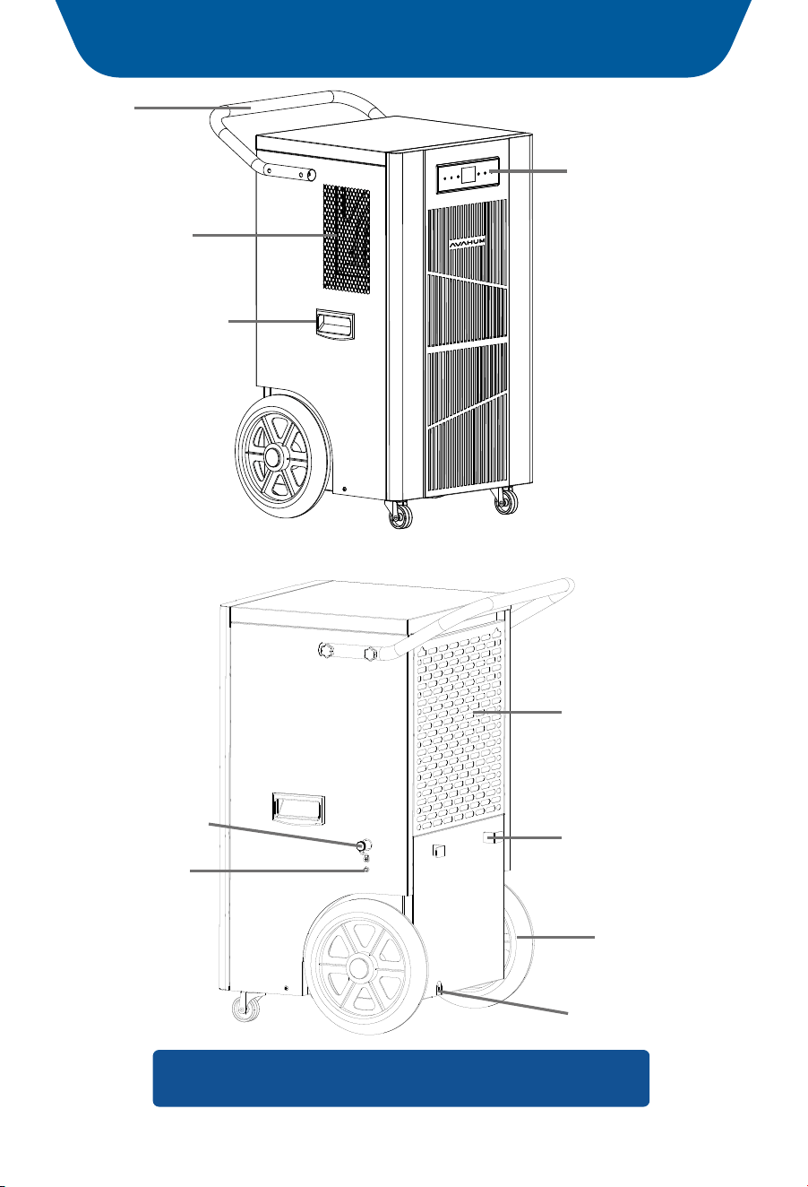
Caster
Handle
Air Outlet
Control Panel
Pump drain outlet
Parts Identification
P.15
Note: Do not obstruct the air inlet and/or outlet.
Air Inlet
Power cord buckle
Gravity drainage outlet
Power cord
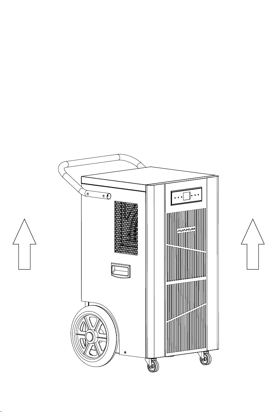
Handle
(both sides)
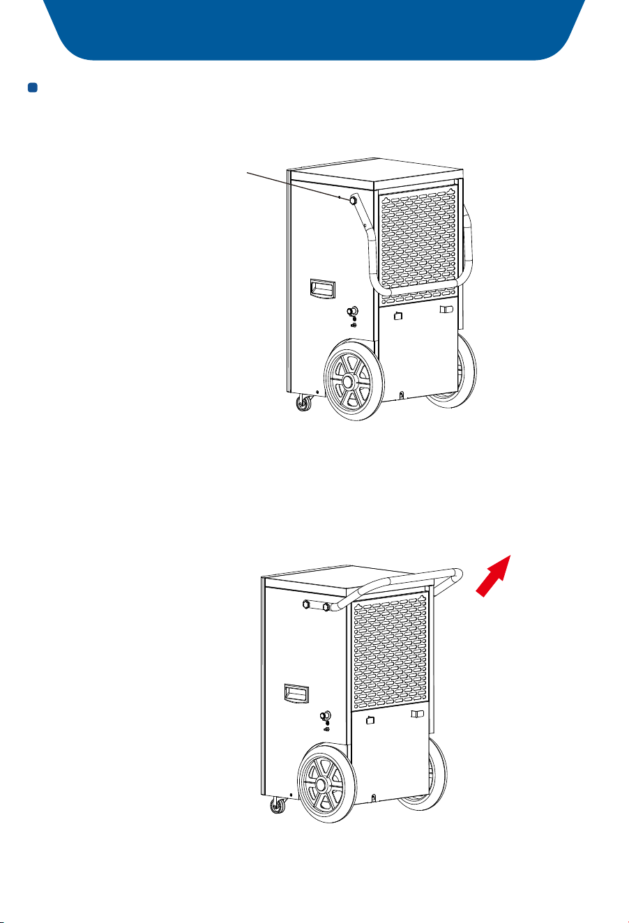
Plum blossom glue
head machine screw
Install the Handle
Ⅰ. Open the package as shown in the picture.
Ⅱ. Locate the M6 hex screws and hex wrench provided in the manual bag.
Ⅲ.Gently lift the handle to a 45-degree angle and position it to align with the M6
nut hole as depicted in the figure. Use the hex wrench to securely tighten the
screws until the handle is firmly fastened to the dehumidifier.
Operation Instructions
P.16
Position Your Dehumidifier
For optimal outcomes, use your dehumidifier in a confined space. •
Shut all entryways and windows. •
Position it clear of obstructions and avoid anything that could obstruct airflow •
in or out of the dehumidifier.
Place the dehumidifier on a flat surface to minimize vibration or noise.Note:
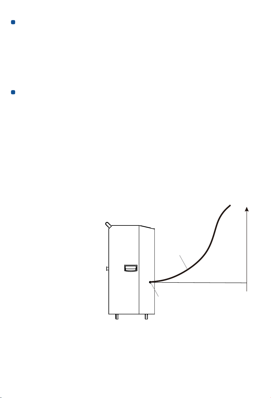
Setting up the Drainage System
The dehumidifier comes equipped with an internal pump for drainage, specially •
designed to handle upward drainage needs.
To prevent any leakage, please ensure the drainage height does not exceed Note:
a distance of more than 16.4 feet from the drainage outlet.
•
Please connect the provided drain hose to the outlet for secure and effective
drainage.
If an alternative drainage hose(inner diameter is 5/8 inch) is used,
Note:
please ensure it is compatible with the drainage outlet to avoid any risk of leakage.
During the drainage process, please keep the hose unobstructed and free from
•
twists or kinks. This will enable the smooth removal of condensate water.
P.17
Upper drainage limit 16.4f
16.4f
Drain Hose
Drain Outlet
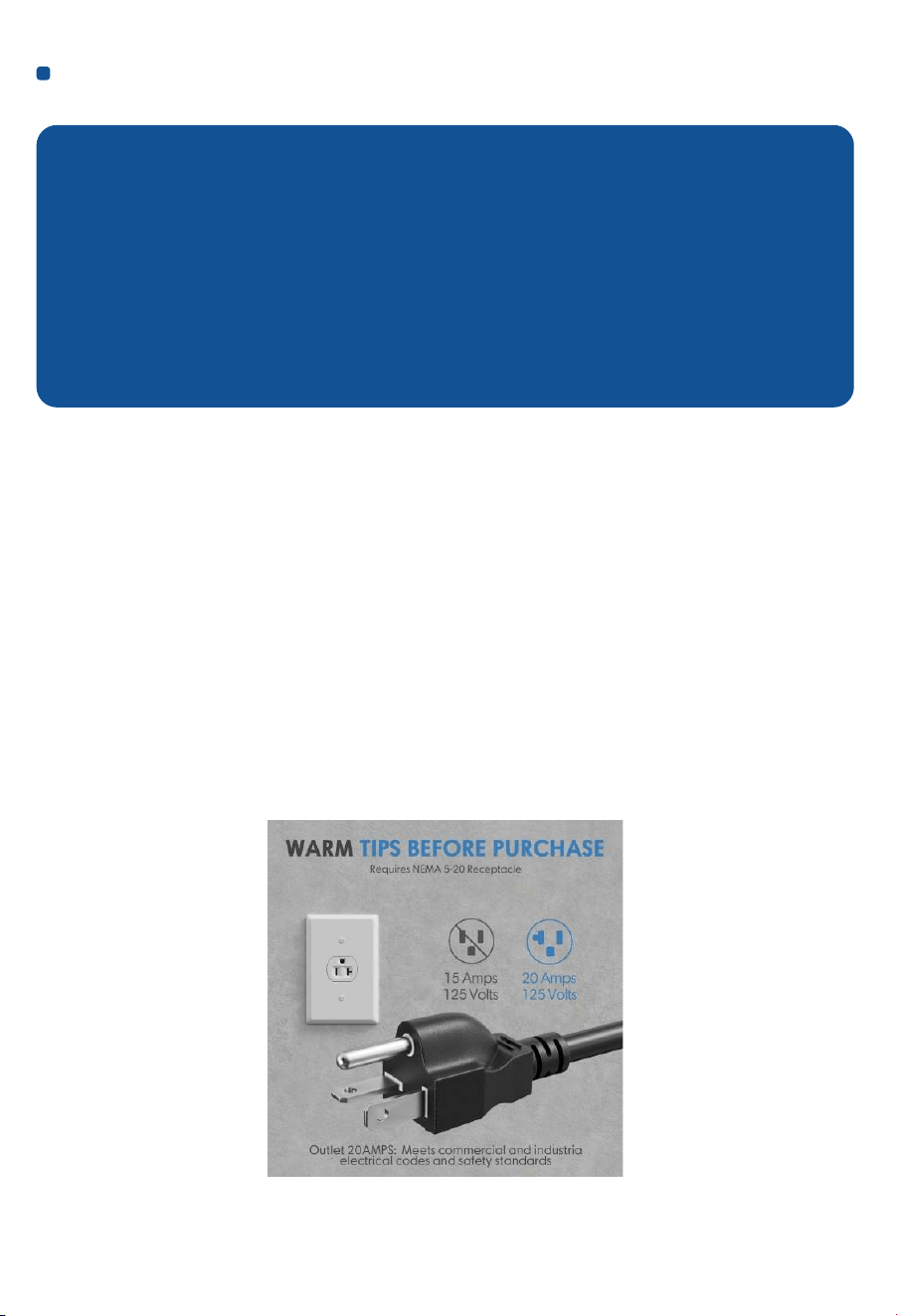
Plug in Electrical Cord
Please let the dehumidifier stand upright for before plugging in for the first time. 24 hours
During the shipping process, the dehumidifier may have been subjected to tilting or
even placed upside down, which can cause the oil in the compressor to become
unsettled. Failure to let the dehumidifier stand upright for the recommended duration
can negatively impact its performance or even shorten its lifespan. Hence, kindly make
sure to follow this crucial step before using the dehumidifier.
IMPORTANT
To properly operate the dehumidifier, please plug it into a GFCI-protected 115-volt
outlet with a rating of at least . Uncoil the power cord and securely
15 amps
connect it to an appropriate outlet. (Recommended for compatibility with NEMA
socket.)5-20
When the dehumidifier is first plugged into AC power, the control panel Note:
display will light up for a second, which is part of the dehumidifier’s self
-diagnosis procedure and no action is required. This indicates that the
dehumidifier is functioning correctly and ready to operate effectively. You
will still need to press the POWER button to turn the dehumidifier on.
If not been operated for over 50 seconds, the control panel will become
dime until pressed buttons again.
P.18
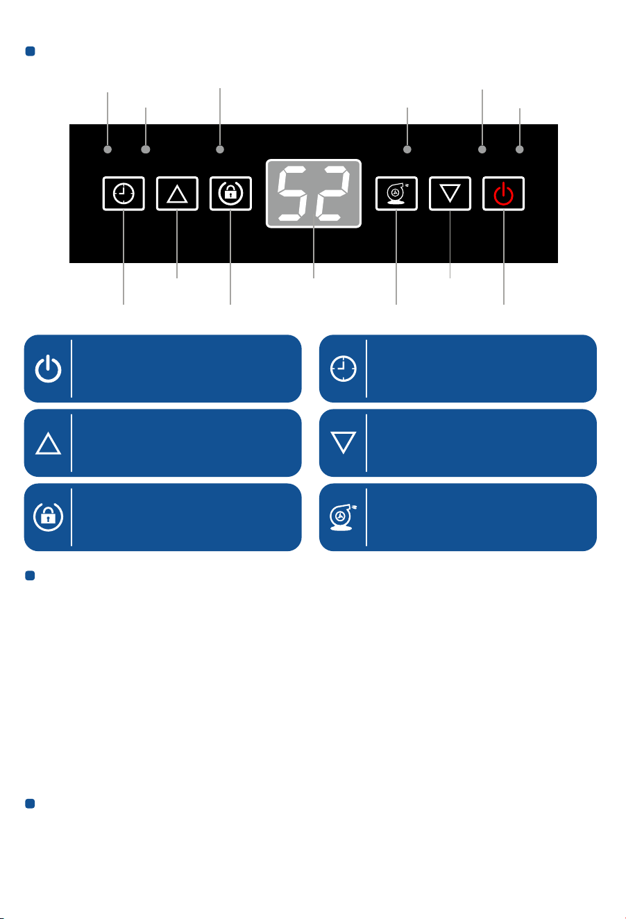
Understand the Control Panel
Timer light
Power Key
Up Key(Humidity Set)
To turn the machine on/off.
Adjust the set humidity
upwards.
Timer Key
Used to set the time on the device,
the setting range is 1-24h.
Down Key(Humidity Set)
Adjust the set humidity
downwards.
P.19
Key description:
In the shutdown state, press once to turn on the machine, Power switch key:
otherwise turn off the machine.
Increase the humidity setting value.
Up key:
decrease the humidity setting value. Down key:
used to set the timing time. Timer key:
For activation and deaction of the child lock function.(Press hold 3S)Lock key:
Pump key: Forced pump drainage to drain water left in the machine (Used when
moving and storing the machine)
Auto-Restart:
If the unit stops unexpectedly due to a power cut, it will restart with the previous
function setting automatically when the power resumes.
TIMERPOWERDOWN
UPPUMP
TIMER
FULL
LOCK
LOCK
POWER
PUMP
DEFROST
Up key Display window
Timer key
Defrosting light
Power light
Full light
Down key
Power key
Lock light
Pump light
Lock key Pump key
Lock Key(Press Hold 3S)
For activation and deaction of
the child lock function.
Pump Key
Forced pump drainage to drain
water left in the machine.
(Used when moving
and storing the machine)

Humidity setting:
In the power-on state, press the "Up" or "Down" key once to enter the humidity
setting state: the display screen flashes the humidity setting value "* *". In the
humidity setting state, press the "Up" or "Down" key to set the humidity, and
the setting range is 10-98% RH. After the key operation is stopped for a few
seconds,the humidity setting state is automatically exited.
The humidity set-point is between 10% and 98%. A humidity setting between
Note:
40% and 60% is recommended for optimal comfort.
After selecting your target value, wait for 5 seconds for the setting to register
automatically,which will ensure that your desired humidity level is set and
maintained. Then, the dehumidifier will automatically stop and restart to
maintain the room humidity level with in a range of +3% of the set point. For
instance, if the set humidity is 50%, the dehumidifier automatically stops
when the room humidity reaches 47% and then automatically restarts when
the room humidity rises back to 53% or higher.
Timer setting:
When the set timing time is reached, the dehumidifier Timed startup:
automatically starts, and the time range can be set to be 0-24 hours.
Timed shutdown: When the set timing time is reached, the dehumidifier
automatically shuts down, and the time range can be set to be 0-24 hours.
NOTE:
Before entering the AUTO ON TIMER setting, ensure that power is being -
supplied to the dehumidifier.
For the AUTO ON setting, please turn on the dehumidifier to select a desired -
humidity level.Otherwise, it will be the same as the previous setting.
Set AUTO ON timer only when the dehumidifier is off or set AUTO OFF timer -
when the dehumidifier is on, but not be able to set both AUTO ON and AUTO OFF
timer at the same time.
The AUTO ON/OFF function won't be cycling.
-
The TIMER function will be disabled when the dehumidifier was powered on/off -
manually.
P.20

Set time to turn on (OFF)
When the machine is turned off, connect the socket and do not press the •
"POWER"button. Press the "TiMER" button, and the timer indicator light will turn
on. Then press the TlMER button to set the timer (1-24H). The device will
automatically turnon when the set time is reached. After turning on, it will not
automatically turn off. but will continue to run according to the set
dehumidification target.
When the machine is working normally for dehumidification, press the "TIMER"
•
button to turn on the timer indicator light. Continue to press the "TIMER" button
to set the timer (1-24H), and the machine will automatically shut down when the
set time is reached. After shutting down, it will not automatically turn on unless
manually turned on.
Example Query the remaining periodic time
Press "Timing". The time displayed in the display area of the dehumidifier control
panel is the remaining reservation time. The original status will be displayed 5
seconds later.
Untiming
Press "Timing" key to enter the setting state of timing startup (shutdown), press
"timing" key to adjust the time to 0 to cancel the setting of timing Settings, timing
indicator off.
Change timing
If you need to change the timing time, reset the timing time.
LOCK Setting
To lock/unlock the Control Panel.
Press and hold the LOCK button for 3-5 seconds to lock or unlock the control panel.
When the LOCK function has been activated,the indicator illuminates, and other
buttons will be disabled.To regain use of the buttons,unlock the control button.
P.21

PUMP Button
Used to start the water pump.
Drainage
During operation, the pump will automatically pump the condensation out via the
drain hose when the pump reservoir is full. No manual intervention! Before moving
the dehumidifier, press and hold the PUMP button for 3-5 seconds to empty the
pump reservoir to avoid water spillage. The PUMP indicator will light up when the
pump is working. The pump will stop working automatically and the PUMP light will
go off when the pump reservoir is almost empty.
TIPS:
The default program setting is gravity drainage. When you block the gravity
drainage outlet, the condensed water is discharged through the water pump
drainage outlet.
Action description:
The fan is turned on, and the compressor is turned on with a delay Startup:
of several seconds.
The compressor is stopped immediately, and the fan is stopped
Shutdown:
after a delay of several seconds.
Without turning on the power supply, the compressor can be turned on again
after it stops running for 3 minutes.
When operating at low ambient temperature, the system
Defrosting function:
will automatically judge whether there is frost, and if there is frost, it will
automatically defrost.
The fan does not stop and the compressor stops.
Defrosting action:
The defrosting indicator is off, and the fan and compressor End of defrosting:
operate according to the humidity control requirements.
Defrost display: When defrosting, the defrosting indicator is on.
Frequent defrosting indicates that the room temperature is too low. It is Note:
recommended to add heat when the room temperature is lower than 60°F
for proper drying.
P.22

Fault Code
(Whether the above fault codes exist depends on whether the actual model has
this function.)
Notice:
EC fails, operation of the machine is not controlled by the buttons on the
operation panel. Please check whether the connection wire between the display
board and the main control board is loose or poor contact caused by other
reasons. If it is caused by looseness, please re-tighten it. If it is caused by loose
wire terminals or broken wires, please contact a professional for repair.
* Dealing with the above problems requires power off.
State Description
The fan starts running, and the compressor starts to run after • Power On:
a delay of a few seconds.
The compressor stops running immediately, and the fan
• Power Off:
stops after a few seconds delay.
To prevent the machine from starting and stopping frequently, there is a •
3-minute delay in the start-up interval.
Turn The Dehumidifier Off
Press the Power Switch to turn the dehumidifier off.
T ,
Note: o protect the compressorthe fan will continue to operate for 5
seconds after the dehumidifier has shut off. So please do not disconnect the
power cord to force the dehumidifier to stop. Always use the power button.
S/N
Error Code
Causes
Ⅰ
1. Faulty Main Control Board.
2. Faulty Display Panel.
3. Faulty Connection Cables.
(Ec)
(Control Panel
Communication
Failure)
Solutions
1. Replace the main control board.
2. Replace the display panel.
3. Replace communication cables.
P.23
!
Ensure the dehumidifier is turned OFF and the plug is removed from
the power socket before cleaning or maintenance is carried out.
Cleaning the Dehumidifier
To clean the dehumidifier body, use a soft damp cloth. Do not submerge or pour
water on the dehumidifier or control panel, as water can damage the electronic
components. Avoid using chemical solvents such as benzene, alcohol, gasoline,
or heavy-duty cleaners, as they can damage or deform the surface.
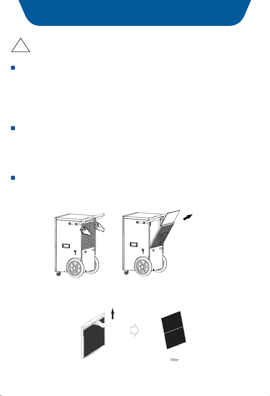
Cleaning the Air Filter
The air filter requires regular cleaning to maintain the dehumidifier's performance.
Clean the air filter every 2 weeks, or more frequently if there's a significant amount
of dander or fur in the air.
Follow the below steps to take the filter out
Hold the top part of both sides of the inlet grill and then pull • To remove the grill:
upward to take the grill out, as illustrated below.
Grasp the filter tab and pull it obliquely up to take out
• To remove the air filter:
the entire filter, as illustrated below.
Maintenance
P.24

When Not Using the Dehumidifier for Long Periods of Time
Wait for one day after turning off the dehumidifier to allow it to drain completely. •
Clean the dehumidifier and air filter thoroughly, ensuring that the dehumidifier •
is dry before storing it.
Wrap the cord and hose and bundle them up to keep them safe.
•
Cover the dehumidifier with a plastic bag. •
Store the dehumidifier upright in a dry, well-ventilated place. •
P.25

Trouble shooting Chart
Below chart will help you solve common problems may occur. If the problem
coming across can not be fixed after troubleshooting or not being listed in the
below troubleshooting chart, please contact AVAHUM customer service to get
professional
support@avahum.com.
Problem
Possible CauseSolution
Dehumidifier does
not operate
No power to dehumidifier
Plug it into a working outlet
Not turned on
Turn the dehumidifier on
Has not set it properly
Make sure the set humidity
level is at 3% lower than the
inlet humidity reading
Error code displays
Contact customer service
Insufficient working time
Too low humidity level
Allow more working time
Try again until the humidity
level exceeds 40%
Filter is blocked
Clean filter
Air Inlet or Outlet is
blocked
Clear the obstructions
Low ambient temperatureHeat up the room
Condensate hose is
blocked
Check hose for restrictions
Dehumidifier
collects little
water
Dehumidifier
operating, but
room not dry
Doors and windows are
open
Seal room from external areas
Trouble Shooting Guide
P.26

Humidity sensor failure
Set the target humidity
percentage value at 10RH%,
the dehumidifier works
normally, which means this
failure does not affect the
function of this dehumidifier.
Repair and replace the
humidity sensor.
Humidity reading
remains at 10RH%,
( far from the actual
room humidity)
Humidity reading
remains at
"99%RH"
(far from the actual
room humidity)
Water on the surface of
the humidity sensor
Please let the dehumidifier
work for a period of time, the
humidity reading will get
normal after the water on the
surface of the humidity sensor
is evaporated.
Humidity sensor failure
The dehumidifier works
normally, which means this
problem does not affect the
function of this dehumidifier.
Repair and replace the
humidity sensor.
Note: It is normal that the dehumidifier pulls warm air out.
Problem
Possible CauseSolution
The dehumidifier has not
been placed properly
Place the dehumidifier in a
horizontal position
Filter is blocked
Clean filter
Abnormal Noise
P.27
If you have an issue with an AVAHUM Product,Please Contact AVAHUM to
Serve Support@avahum.com

Specifications
DEHUMIDIFIER
P.28
MODEL
POWER SOURCE
RATED POWER
RATED CURRENT
MOTOR COMPRESSOR
REFRIGERANT
MAXIMUM ALLOWABLE SUCTION PRESSURE
MAXIMUM ALLOWABLE DISCHARGE PRESSURE
MAXIMUM ALLOWABLE PRESSURE
MOISTURE REMOVAL CAPACITY(65℉,60%RH)
MOISTURE REMOVAL (80℉,60%RH)
MOISTURE REMOVAL(86℉,80%RH)
MOISTURE REMOVAL (95℉,90%RH)
MOTOR FLA
INPUT POWER(80℉,60%RH)
INPUT CURRENT(80℉,60%RH)
RLA:13.5A LRA:54A
R32/485g(17.1ozs)
6.5MPa
4.0MPa
1.3A
1.7MPa
230 Pints/Day
85 Pints/Day
130 Pints/Day
320 Pints/Day
CFT320P
1700W
15.0A
120V 60Hz
1100W
11A
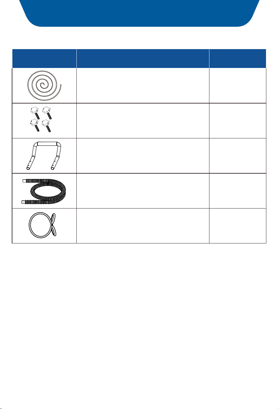
Parts List
PictureName
Quantity
1PC
4PCS
Pump Drain hose
P.29
Machine tooth screws
with rubber head
Handle
1PC
Drain Hose
1PC
Drain Pipes Fastening Rings
1PC
Limited Warranty
AVAHUM offers a limited 1-year free warranty on this CFT320P dehumidifier, with
original proof of purchase (typically you maybe only requested to offer the order
number or other information to prove a genuine purchase, instead of an invoice)
and where a defect has arisen, wholly or substantially, as a result of faulty
manufacture, parts or workmanship during the warranty period.
During the warranty period, for the damaged part, we will provide a replacement
part if it can be restored to normal use by replacing parts.
The warranty does not apply where damage is caused by other factors, including
without limitation:
Normal wear and tear;
Abuse, mishandling, accident, or failure to follow operating instructions;
Exposure to liquid or infiltration of foreign particles;
Servicing or modifications of the product other than by AVAHUM.
We will try our best to inspect the dehumidifier through photos or videos to
troubleshoot and ensure that we can better solve the problem for you.
These are our general terms for warranty service, but we always urge our
customers to reach out to us with any issue, regardless of warranty terms.
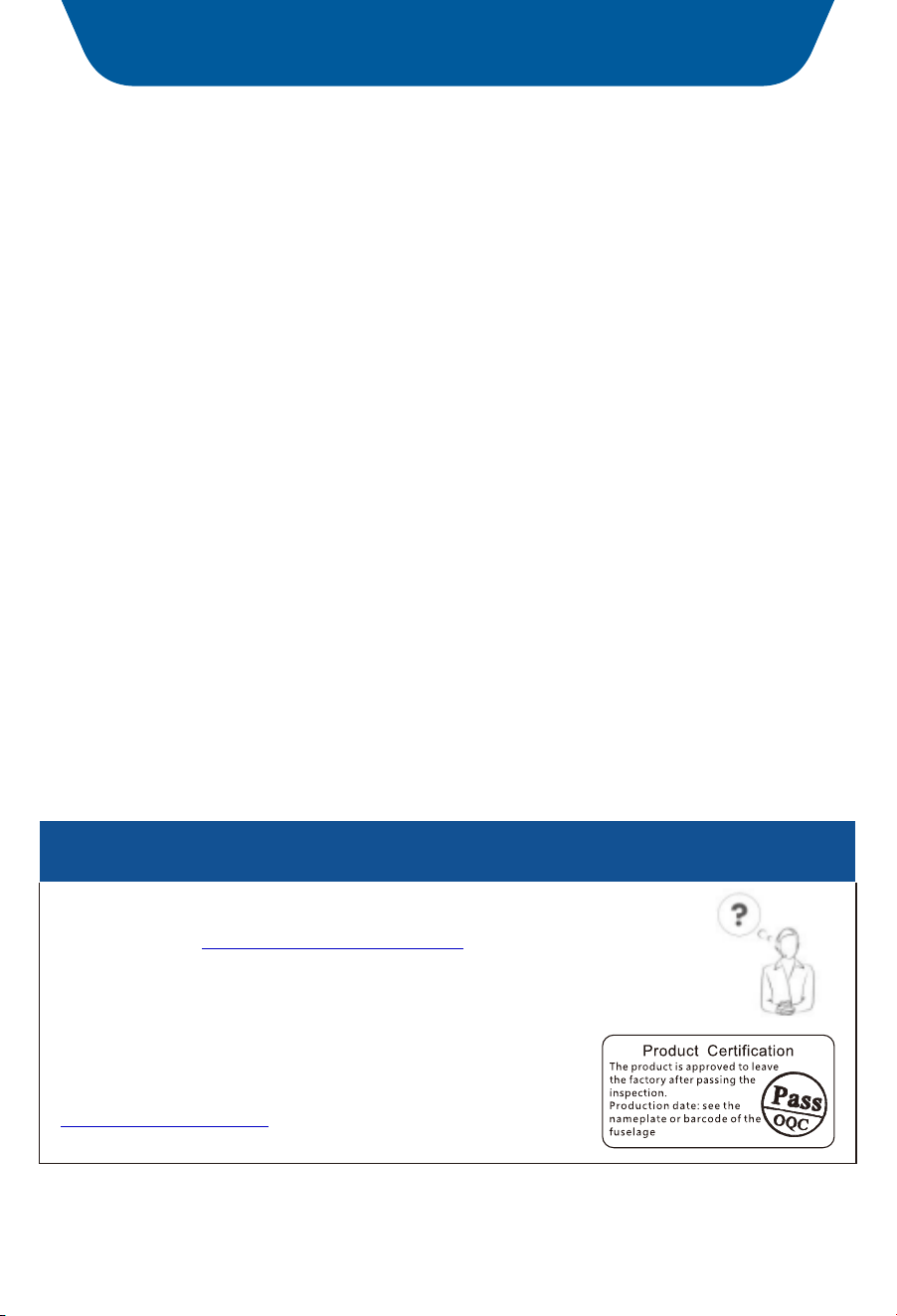
Warranty and Service
If you have an issue with an AVAHUM product, please
contact us at , and
Support@avahum.com
we will do our best to resolve it for you.
Support Hours
24 Hours available
*Please have your order number before
contacting customer support.
www.avahum.com
P.30