Atomic 3000 LED
User Manual
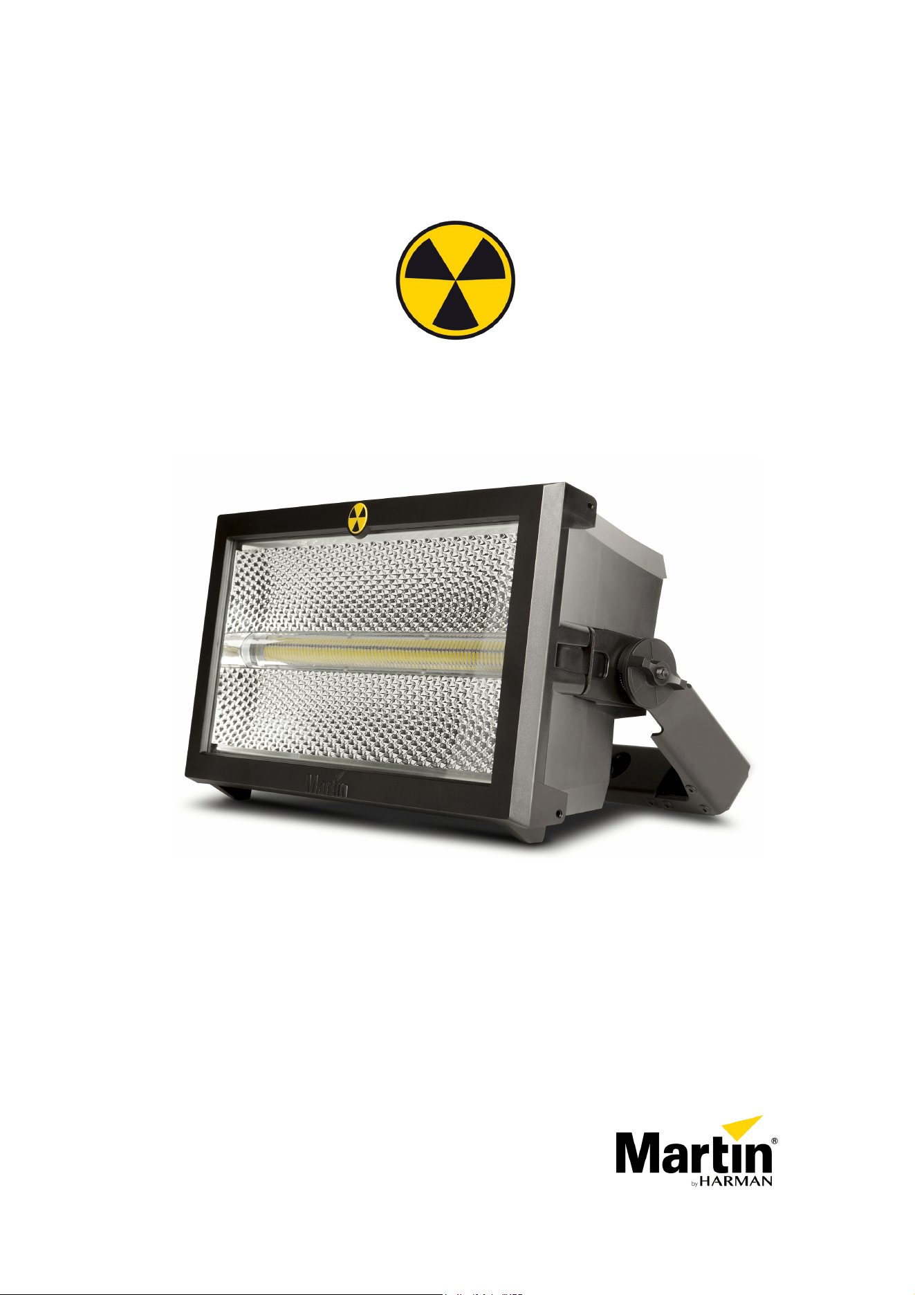
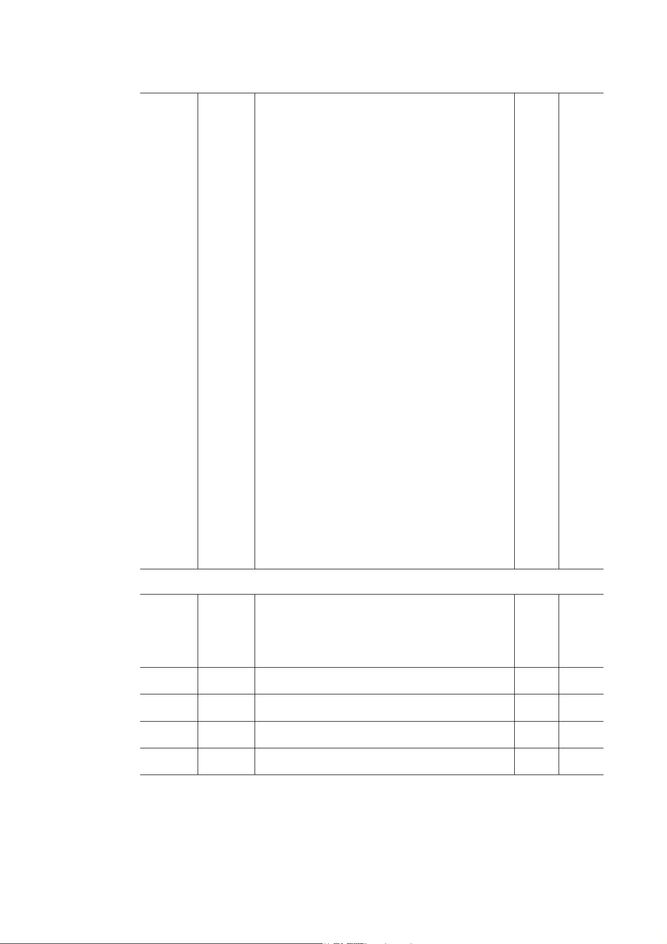
Dimensions
All dimensions are in millimeters
442
424
245
234
Ø270
160
1064 x 90
Ø13
57
106
Ø332
©2001-2023 HARMAN PROFESSIONAL DENMARK ApS. All rights reserved. Features, specifications and appearance are subject
to change without notice. HARMAN PROFESSIONAL DENMARK ApS and all affiliated companies disclaim liability for any injury,
damage, direct or indirect loss, consequential or economic loss or any other loss occasioned by the use of, inability to use or reliance
on the information contained in this document. Martin is a registered trademark of HARMAN PROFESSIONAL DENMARK ApS
registered in the United States and/or other countries.
HARMAN PROFESSIONAL DENMARK ApS
, Olof Palmes Allé 44, 8200 Aarhus N, Denmark
HARMAN PROFESSIONAL SOLUTIONS U.S.
, 8500 Balboa Blvd., Northridge CA 91329, USA
www.martin.com
Atomic 3000 LED User Manual, P/N 35000290, Rev. C

Dimensions
3
Contents
Dimensions . . . . . . . . . . . . . . . . . . . . . . . . . . . . . . . . . . . . . . . . . . . . . . . . . . . . . . . . . . . . . . . . . . . . . . . . 2
Safety Information. . . . . . . . . . . . . . . . . . . . . . . . . . . . . . . . . . . . . . . . . . . . . . . . . . . . . . . . . . . . . . . . . . 4
Fixture overview . . . . . . . . . . . . . . . . . . . . . . . . . . . . . . . . . . . . . . . . . . . . . . . . . . . . . . . . . . . . . . . . . . . 7
Introduction . . . . . . . . . . . . . . . . . . . . . . . . . . . . . . . . . . . . . . . . . . . . . . . . . . . . . . . . . . . . . . . . . . . . . . . . 8
Using for the first time . . . . . . . . . . . . . . . . . . . . . . . . . . . . . . . . . . . . . . . . . . . . . . . . . . . . . . . . . . . . . . . 8
AC power . . . . . . . . . . . . . . . . . . . . . . . . . . . . . . . . . . . . . . . . . . . . . . . . . . . . . . . . . . . . . . . . . . . . . . . . . . 9
Power voltage . . . . . . . . . . . . . . . . . . . . . . . . . . . . . . . . . . . . . . . . . . . . . . . . . . . . . . . . . . . . . . . . . . . . . 9
Power cables and power plug . . . . . . . . . . . . . . . . . . . . . . . . . . . . . . . . . . . . . . . . . . . . . . . . . . . . . . . . . 9
Data link . . . . . . . . . . . . . . . . . . . . . . . . . . . . . . . . . . . . . . . . . . . . . . . . . . . . . . . . . . . . . . . . . . . . . . . . . . 10
Tips for reliable data transmission. . . . . . . . . . . . . . . . . . . . . . . . . . . . . . . . . . . . . . . . . . . . . . . . . . . . . 10
Connecting the data link . . . . . . . . . . . . . . . . . . . . . . . . . . . . . . . . . . . . . . . . . . . . . . . . . . . . . . . . . . . . 10
Physical installation . . . . . . . . . . . . . . . . . . . . . . . . . . . . . . . . . . . . . . . . . . . . . . . . . . . . . . . . . . . . . . . 11
Tilt adjustment . . . . . . . . . . . . . . . . . . . . . . . . . . . . . . . . . . . . . . . . . . . . . . . . . . . . . . . . . . . . . . . . . . . . 11
Fastening the fixture to a flat surface. . . . . . . . . . . . . . . . . . . . . . . . . . . . . . . . . . . . . . . . . . . . . . . . . . . 11
Mounting the fixture on a truss . . . . . . . . . . . . . . . . . . . . . . . . . . . . . . . . . . . . . . . . . . . . . . . . . . . . . . . 12
Atomic Colors scroller . . . . . . . . . . . . . . . . . . . . . . . . . . . . . . . . . . . . . . . . . . . . . . . . . . . . . . . . . . . . . . 13
Setup. . . . . . . . . . . . . . . . . . . . . . . . . . . . . . . . . . . . . . . . . . . . . . . . . . . . . . . . . . . . . . . . . . . . . . . . . . . . . 15
Control panel and menu navigation. . . . . . . . . . . . . . . . . . . . . . . . . . . . . . . . . . . . . . . . . . . . . . . . . . . . 15
DMX address setting . . . . . . . . . . . . . . . . . . . . . . . . . . . . . . . . . . . . . . . . . . . . . . . . . . . . . . . . . . . . . . . 16
DMX modes . . . . . . . . . . . . . . . . . . . . . . . . . . . . . . . . . . . . . . . . . . . . . . . . . . . . . . . . . . . . . . . . . . . . . . 16
Fixture ID . . . . . . . . . . . . . . . . . . . . . . . . . . . . . . . . . . . . . . . . . . . . . . . . . . . . . . . . . . . . . . . . . . . . . . . . 16
Personality. . . . . . . . . . . . . . . . . . . . . . . . . . . . . . . . . . . . . . . . . . . . . . . . . . . . . . . . . . . . . . . . . . . . . . . 17
Default and custom settings . . . . . . . . . . . . . . . . . . . . . . . . . . . . . . . . . . . . . . . . . . . . . . . . . . . . . . . . . 18
Fixture information readouts . . . . . . . . . . . . . . . . . . . . . . . . . . . . . . . . . . . . . . . . . . . . . . . . . . . . . . . . . 18
DMX signal monitoring. . . . . . . . . . . . . . . . . . . . . . . . . . . . . . . . . . . . . . . . . . . . . . . . . . . . . . . . . . . . . . 19
Test sequences . . . . . . . . . . . . . . . . . . . . . . . . . . . . . . . . . . . . . . . . . . . . . . . . . . . . . . . . . . . . . . . . . . . 19
Manual control . . . . . . . . . . . . . . . . . . . . . . . . . . . . . . . . . . . . . . . . . . . . . . . . . . . . . . . . . . . . . . . . . . . . 19
Operation and effects . . . . . . . . . . . . . . . . . . . . . . . . . . . . . . . . . . . . . . . . . . . . . . . . . . . . . . . . . . . . . 20
Strobe effects. . . . . . . . . . . . . . . . . . . . . . . . . . . . . . . . . . . . . . . . . . . . . . . . . . . . . . . . . . . . . . . . . . . . . 20
Blinder effects . . . . . . . . . . . . . . . . . . . . . . . . . . . . . . . . . . . . . . . . . . . . . . . . . . . . . . . . . . . . . . . . . . . . 20
Aura RGB Color. . . . . . . . . . . . . . . . . . . . . . . . . . . . . . . . . . . . . . . . . . . . . . . . . . . . . . . . . . . . . . . . . . . 20
Pre-programmed FX . . . . . . . . . . . . . . . . . . . . . . . . . . . . . . . . . . . . . . . . . . . . . . . . . . . . . . . . . . . . . . . 20
Beam color with the Atomic Colors scroller . . . . . . . . . . . . . . . . . . . . . . . . . . . . . . . . . . . . . . . . . . . . . . 21
Beam blackout after loss of data signal. . . . . . . . . . . . . . . . . . . . . . . . . . . . . . . . . . . . . . . . . . . . . . . . . 21
RDM. . . . . . . . . . . . . . . . . . . . . . . . . . . . . . . . . . . . . . . . . . . . . . . . . . . . . . . . . . . . . . . . . . . . . . . . . . . . 21
Service and maintenance. . . . . . . . . . . . . . . . . . . . . . . . . . . . . . . . . . . . . . . . . . . . . . . . . . . . . . . . . . 22
Cleaning. . . . . . . . . . . . . . . . . . . . . . . . . . . . . . . . . . . . . . . . . . . . . . . . . . . . . . . . . . . . . . . . . . . . . . . . . 22
Control menu service utilities. . . . . . . . . . . . . . . . . . . . . . . . . . . . . . . . . . . . . . . . . . . . . . . . . . . . . . . . . 23
Firmware installation . . . . . . . . . . . . . . . . . . . . . . . . . . . . . . . . . . . . . . . . . . . . . . . . . . . . . . . . . . . . . . . 23
Fixture readouts. . . . . . . . . . . . . . . . . . . . . . . . . . . . . . . . . . . . . . . . . . . . . . . . . . . . . . . . . . . . . . . . . . . 25
DMX protocol . . . . . . . . . . . . . . . . . . . . . . . . . . . . . . . . . . . . . . . . . . . . . . . . . . . . . . . . . . . . . . . . . . . . . 26
3-Channel DMX Mode . . . . . . . . . . . . . . . . . . . . . . . . . . . . . . . . . . . . . . . . . . . . . . . . . . . . . . . . . . . . . . 26
4-Channel DMX Mode . . . . . . . . . . . . . . . . . . . . . . . . . . . . . . . . . . . . . . . . . . . . . . . . . . . . . . . . . . . . . . 26
Extended DMX Mode. . . . . . . . . . . . . . . . . . . . . . . . . . . . . . . . . . . . . . . . . . . . . . . . . . . . . . . . . . . . . . . 27
FX: pre-programmed effects . . . . . . . . . . . . . . . . . . . . . . . . . . . . . . . . . . . . . . . . . . . . . . . . . . . . . . . . . 30
Onboard control menus. . . . . . . . . . . . . . . . . . . . . . . . . . . . . . . . . . . . . . . . . . . . . . . . . . . . . . . . . . . . 31
Service and display messages. . . . . . . . . . . . . . . . . . . . . . . . . . . . . . . . . . . . . . . . . . . . . . . . . . . . . 33
Warning messages . . . . . . . . . . . . . . . . . . . . . . . . . . . . . . . . . . . . . . . . . . . . . . . . . . . . . . . . . . . . . . . . 33
Error messages . . . . . . . . . . . . . . . . . . . . . . . . . . . . . . . . . . . . . . . . . . . . . . . . . . . . . . . . . . . . . . . . . . . 34
Troubleshooting . . . . . . . . . . . . . . . . . . . . . . . . . . . . . . . . . . . . . . . . . . . . . . . . . . . . . . . . . . . . . . . . . . 35
Specifications . . . . . . . . . . . . . . . . . . . . . . . . . . . . . . . . . . . . . . . . . . . . . . . . . . . . . . . . . . . . . . . . . . . . . 36
4
Atomic™ 3000 LED user manual
Safety Information
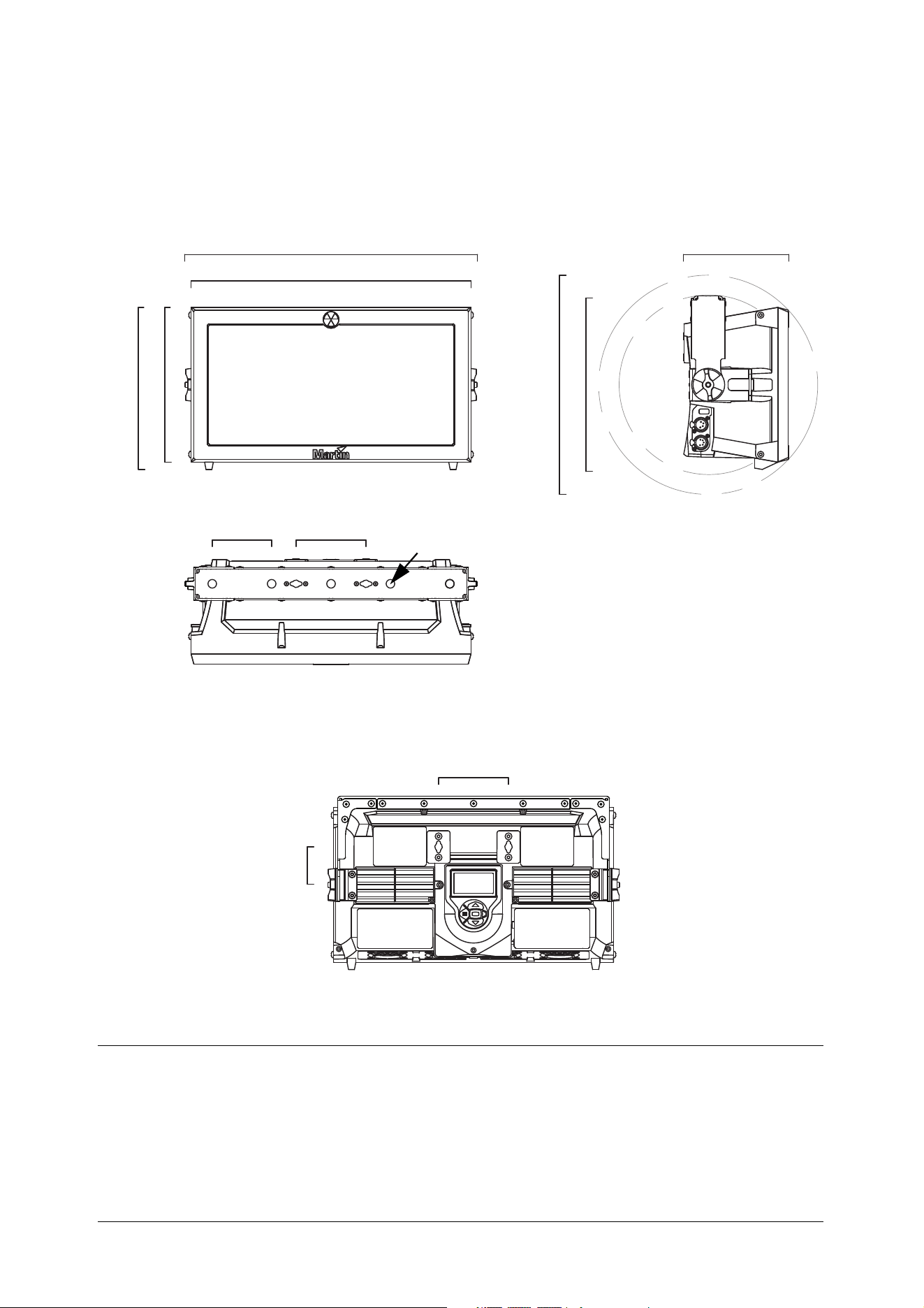
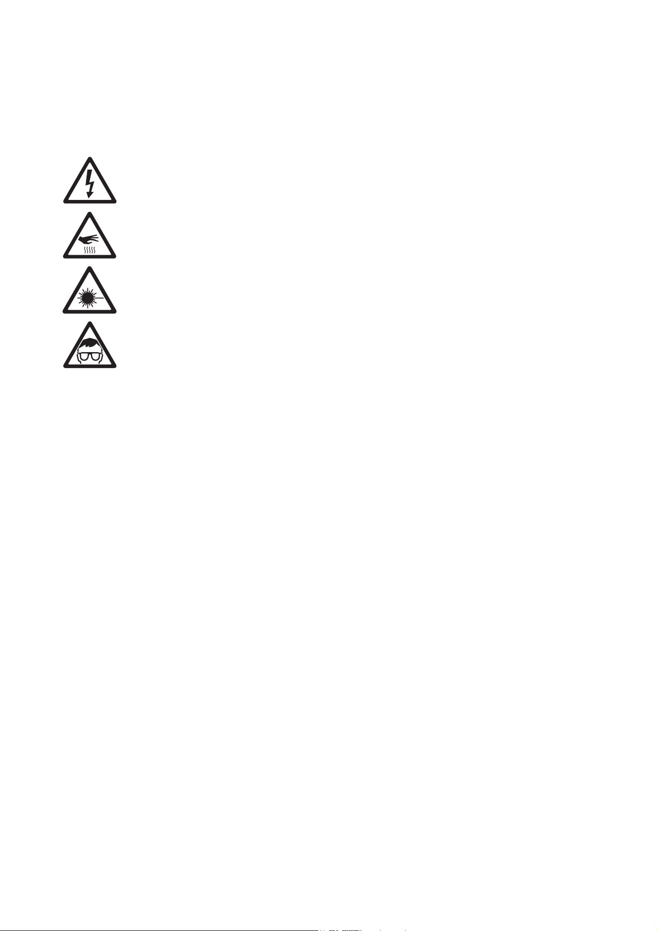
The following symbols are used to identify important safety information on the product and in this manual:
Warning! Risk Group 2 LED product according to EN 62471 and IEC/TR 62778. Do not view the light
output with optical instruments or any device that may concentrate the beam.
This lighting fixture must be installed by a qualified technician. The safety of the installation is the
responsibility of the installer. The fixture presents risks of severe injury or death due to fire hazards, electric
shock and falls. Flashing light is also known to trigger epileptic seizures in persons who are sensitive to it.
The fixture can produce powerful, concentrated light that can create a fire hazard or a risk of eye injury if the
safety precautions below are not followed.
Read this manual before installing, powering or servicing the fixture. Follow the safety precautions and
observe all warnings in this manual and printed on the fixture.
The Atomic 3000 LED is for professional use as a stage light only. It is not for household or general lighting
applications. Respect all locally applicable laws, codes and regulations when installing, operating or
servicing the fixture.
Install, operate and service Martin products only as directed in their user documentation, or you may create
a safety hazard or cause damage that is not covered by product warranties. Refer any service operation not
described in the product’s user documentation to an authorized Martin service technician. Do not try to
carry out any such operation yourself, as doing so may present a health or safety risk. It may also cause
damage or malfunction and it may void your product warranty.
Before you install, operate or service the Atomic 3000 LED, check the Martin website and make sure that
you have the latest user documentation for the fixture. Document revisions are indicated at the bottom of
page 2. The latest product user documentation is available for download from the Atomic 3000 LED product
page on the Martin website at www.martin.com.
Technical Support
If you have questions about how to install or operate the fixture safely, please contact Harman Professional
Technical support:
• For technical support in North America, please contact: HProTechSupportUSA@harman.com
Phone: (844) 776-4899
• For technical support outside North America, please contact your national distributor.
WARNING!
Read the safety precautions in this section before
installing, powering, operating or servicing this
product.
WARNING!
Safety hazard.
Risk of severe
injury or death.
WARNING!
Hazardous
voltage. Risk of
lethal or severe
electric shock.
WARNING!
Fire hazard.
WARNING!
Burn hazard. Hot
surface. Do not
touch.
WARNING!
Powerful light
emission. Risk of
eye injury.
WARNING! Refer
to user manual
for important
safety
information.
Safety Information
5
PROTECTION FROM ELECTRIC SHOCK
• The Atomic 3000 LED fixture is for indoor use only. Do not expose it to rain or moisture.
• Disconnect the fixture from AC power before carrying out any installation or service work and when the
fixture is not in use.
• Ensure that the fixture is electrically connected to ground (earth).
• Apply AC mains power to the fixture at 100 - 240 VAC nominal, 50/60 Hz only.
• Use only a source of AC power that complies with local building and electrical codes and has both
overload and ground-fault (earth-fault) protection.
• Before using the fixture, check that all power distribution equipment and cables are in perfect condition
and rated for the current requirements of all connected devices.
• Isolate the fixture from power immediately if the power cable, power plug or any seal, cover or other part is
damaged, defective, deformed, wet or showing signs of overheating. Do not reapply power until repairs
have been completed and any defective parts have been replaced with new items.
• The fixture’s DMX transceiver is isolated, SELV design, to prevent ground loops and for safety reasons.
• The cable used to connect the fixture to AC power must be 14 AWG or 1.5 mm
2
minimum conductor size
and heat-resistant to 90° C (194° F) minimum. It must have three conductors and an outer cable diameter
of 5 - 15 mm (0.2 - 0.6 in.). In the USA and Canada, the cable must be UL/CSA recognized, hard usage,
type SJT or equivalent. In the EU, the cable must be type H05VV-F or equivalent.
• Connect only a cable with a Neutrik PowerCON TRUE1 TOP NAC3FX-W female connector to the fixture’s
power input socket.
• Refer any service operation not described in the fixture’s user documentation to Martin Service or an
authorized Martin Service partner.
• The light source contained in the fixture shall be replaced by Martin Service or an authorized Martin
Service partner only.
• Do not use the fixture at an altitude of more than 2000 m (6570 ft.) above sea level.
PROTECTION FROM BURNS AND FIRE
• Do not operate the fixture if the ambient temperature (Ta) exceeds 40° C (104° F).
• The exterior of the fixture becomes hot during use. After 5 minutes of operation a surface temperature of
70° C (158° F) shall be expected, and the maximum steady state is 80° C (176° F). Avoid contact by
persons and materials. Allow the fixture to cool for at least 10 minutes before handling.
• Keep all combustible materials (e.g. fabric, wood, paper) at least 20 cm (8 in.) away from the fixture.
• Keep flammable materials (e.g. volatile liquids, pyrotechnics, fuel of any kind) well away from the fixture.
• Ensure that there is free and unobstructed airflow around the fixture.
• Do not illuminate surfaces within 1 m (3 ft. 4 in.) of the Atomic 3000 LED.
• Do not expose the front glass to sunlight or other strong light source from any angle. Lenses can focus the
sun's rays inside the fixture, creating a potential fire hazard.
• Do not attempt to bypass thermostatic switches or fuses.
• Do not modify the fixture in any way not described in this user manual or install other than genuine Martin
parts. Do not stick filters, masks or other materials onto any lens or other optical component. Use only
accessories approved by Martin to mask or modify the light beam.
PROTECTION FROM EYE INJURY
• Do not stare at the light source.
• Do not look at LEDs with magnifiers, telescopes, binoculars or similar optical instruments that may
concentrate the light output.
• Ensure that persons are not looking at the fixture when the fixture lights up suddenly. This can happen
when power is applied, when the fixture receives a DMX signal, or when certain control menu items are
selected.
• Do not operate the fixture with missing or damaged covers, shields or any optical component.
• Disconnect the fixture from power at all times when the fixture is not in use.
• Provide well-lit conditions to reduce the pupil diameter of anyone working on or near the fixture.
• This fixture corresponds to Risk Group 2 according to EN 62471 and IEC/TR 62778. It emits possibly
hazardous optical radiation.
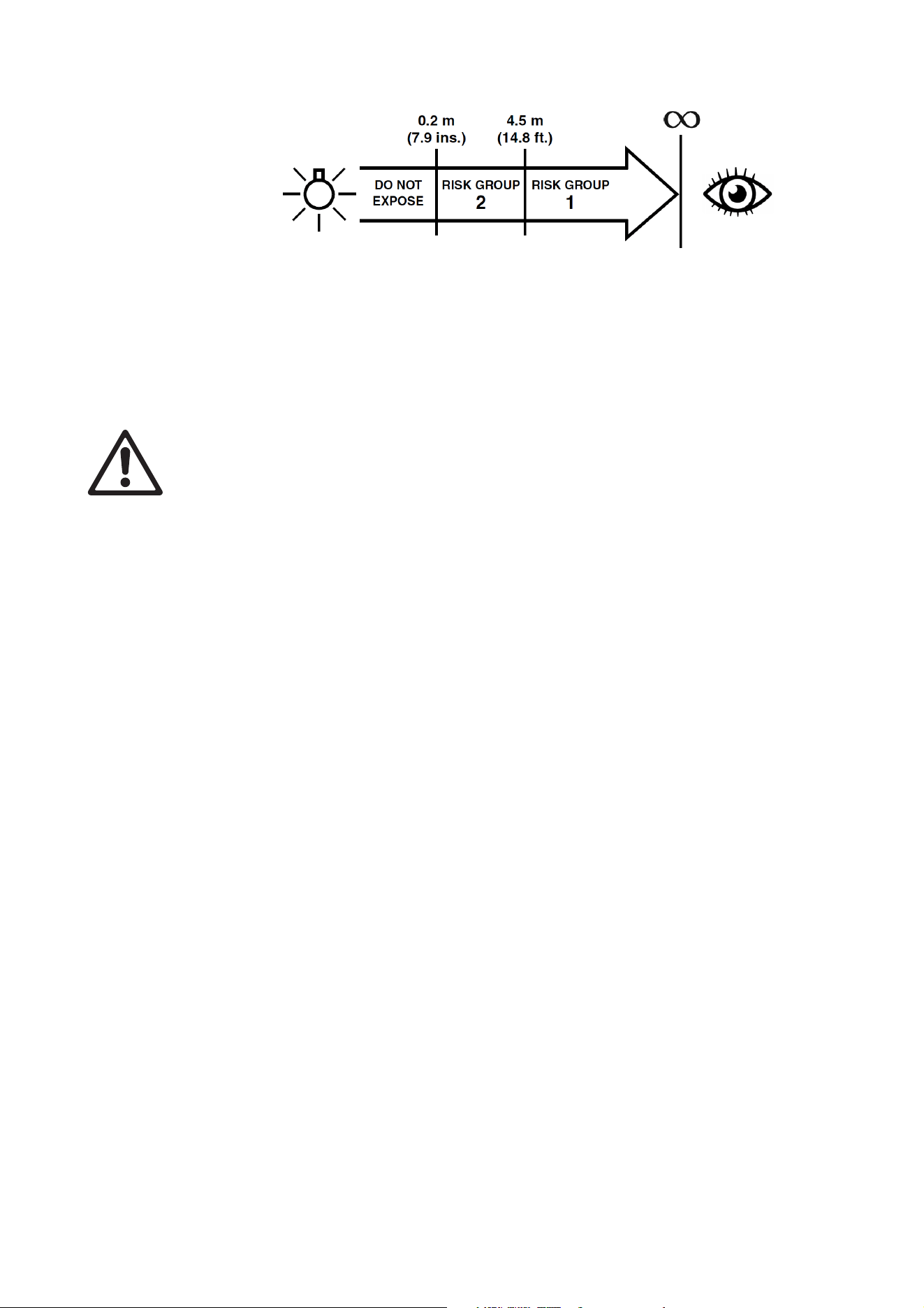
• The fixture falls into the Risk Group categories shown below according to EN 62471 and IEC/TR 62778
under worst-case conditions:
• At a distance of less than 0.2 m (7.9 in.) from the fixture, the light output can potentially cause eye or skin
injury before an exposed person's natural aversion responses (blink reflex and reaction to skin discomfort)
can protect them. At distances greater than 0.2 m (7.9 in.), potential eye and skin injury hazards from the
light output are normally prevented by natural aversion reflexes.
• Position the fixture so that persons cannot be exposed to the fixture's light output at a distance of less
than 0.2 m (7.9 in.) from the fixture, and so that prolonged staring into the light output at less than 4.5 m
(14.8 ft.) from the fixture is not expected.
PROTECTION FROM INJURY
• To guard against risks from epileptic seizure:
- Do not operate the fixture near stairways, in corridors or near public exits.
- Provide advance notice that strobe lighting is in use. Display advisory notices at the point of ticket sales,
on tickets if possible, in the program, and at the entrance(s) to the venue.
- Avoid extended periods of continuous flashing, particularly at frequencies of 10 to 20 flashes per
second. At flash rates below 5 flashes per second, it is estimated that only 5% of flicker-sensitive
persons will be at risk of seizure.
- Make sure that personnel at the venue are trained in the care of a person who is having an epileptic
seizure and able to provide care if necessary.
- If strobes are in use and a person has a seizure, switch the strobes off immediately.
- Mount strobes as high above head height as practicable.
• Fasten the fixture securely to a fixed surface or rigging structure when in use. The fixture is not portable
when installed.
• Block access below the work area and work from a stable platform whenever installing, servicing or
moving the fixture.
• Make sure that all fasteners used to install the fixture are minimum grade 8.8 steel. Use unworn
self-locking nuts on bolts and machine screws.
• When suspending the fixture, ensure that the supporting structure and all hardware used can hold at least
six times the weight of all the devices they support.
• Install the fixture only as described under “Physical installation” on page 11. In all truss-mount
installations where the fixture is not hanging vertically in ‘free hanging mode’, use a rigging clamp that
completely encircles the truss chord, and bolt the clamp directly to the fixture’s mounting bracket with a
grade 8.8 strength bolt and unworn self-locking nut. Do not use any type of clamp that does not
completely encircle the truss chord and do not use an omega bracket or any other intermediary rigging
hardware.
• If you install the fixture in a location where it may cause injury or damage if it falls, install as described in
this manual a secondary attachment such as a safety cable that is approved by an official body such as
TÜV as a safety attachment for the weight that it secures.The safety cable must comply with EN
60598-2-17 Section 17.6.6 and be capable of bearing a static suspended load that is six times the weight
of the fixture and all installed accessories. Fasten the safety cable to a secure anchoring point and to a
safety cable attachment point provided on the fixture and indicated in this manual so that the safety cable
will catch and hold the fixture if a primary attachment fails. Do not use any other part of the fixture as a
safety cable attachment point.
• If the safety cable attachment point becomes deformed, do not install the fixture. Have the fixture repaired
by an authorized Martin service partner.
• Check that all external covers and rigging hardware are securely fastened.
Fixture overview
7
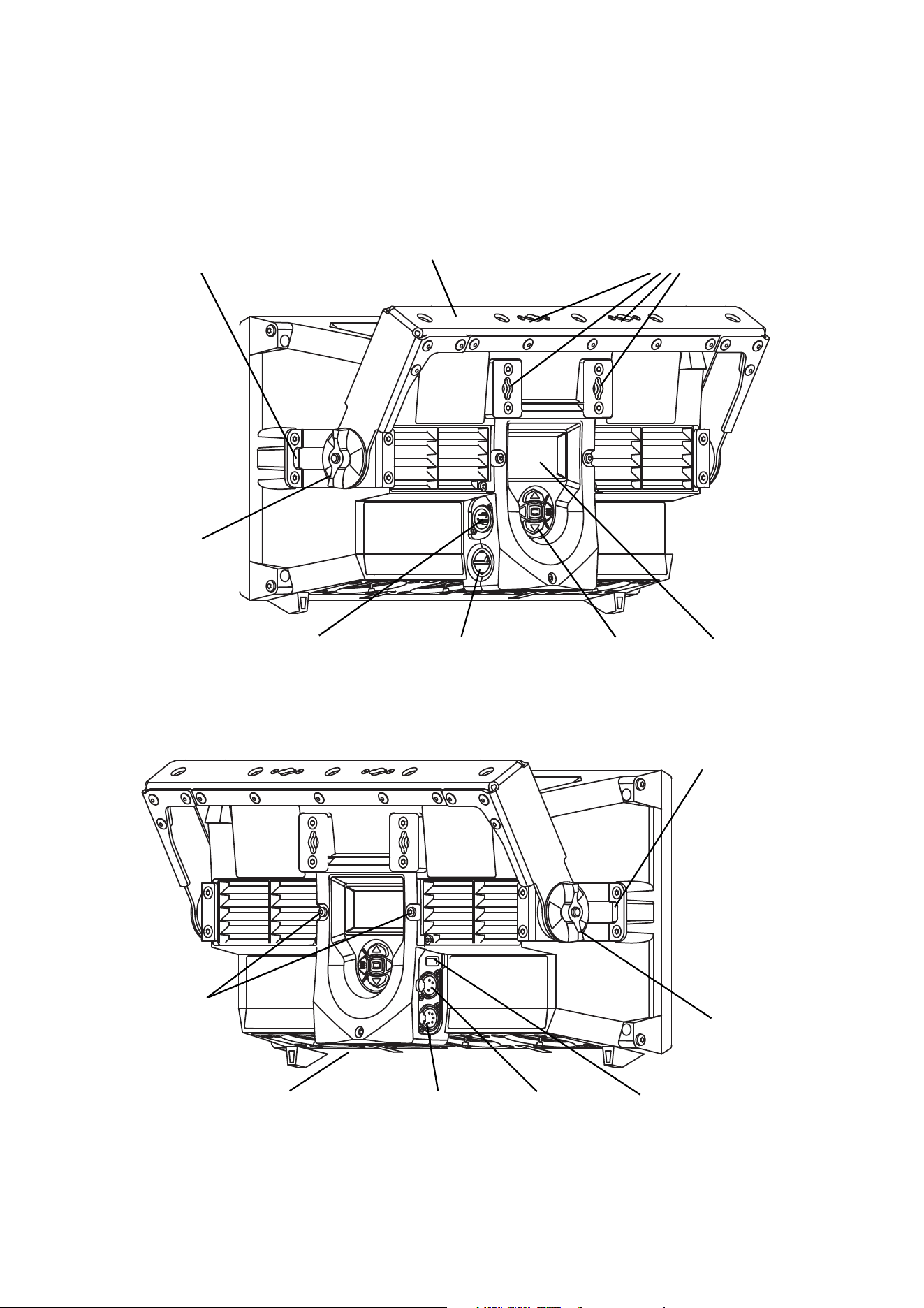
Fixture overview
Control buttons
Atomic
Display
Figure 1: Fixture overview
DMX input
DMX output
AC mains power
input
USB
Safety cable
attachment point
Quarter-turn fastener
attachment points
Safety cable
attachment point
Colors
Tilt
adjustment
Tilt
adjustment
Base of fixture,
base fans
DMX output
Air filter grill
release screws
power + data
Mounting bracket
wheel
wheel
(use for Atomic Colors
if installed)
8
Atomic™ 3000 LED user manual
Introduction
Thank you for selecting the Atomic 3000 LED™, an intelligent lighting fixture from Martin Professional®.
This powerful LED-based stroboscopic effect light builds on the industry-standard Martin Atomic 3000
DMX™ strobe effect, and features:
• A ‘Beam’ LED array that gives powerful strobe and blinder effects
• An ‘Aura’ LED array that lights up the front surface of the fixture and has RGB color mixing
• Pre-programmed FX that can be synchronized, with or without offsets, in multiple fixtures
• Onboard control panel and backlit LCD display
• DMX control and RDM fixture management
• Atomic Colors color scroller unit (optional accessory)
For the latest firmware updates, documentation and other information about this and all Martin Professional
products, please visit the Martin website at http://www.martin.com
Using for the first time
Warning! Read “Safety Information” on page 4 before installing, powering, operating or servicing
the Atomic 3000 LED.
Important! The Atomic 3000 LED is a rugged fixture but it must be protected from environmental
factors such as excessive physical shocks and vibration during transportation and storage.
Before applying power to the fixture:
• Check the Martin Professional website at www.martin.com for the most recent user documentation and
technical information about the Atomic 3000 LED. Martin user manual revisions are identified by the
revision letter at the bottom of page 2.
• Carefully review “Safety Information” starting on page 4.
• Check that the local AC mains power source is within the fixture’s power voltage and frequency ranges.
• Check that the power input cable meets the requirements listed under “Protection from electric shock” on
page 5.
• See “Power cables and power plug” on page 9. If drawing power from a mains power outlet, install a
suitable power plug on the power input cable.
AC power
9
AC power
Warning! Read “Safety Information” on page 4 before connecting the Atomic 3000 LED to AC mains
power.
Warning! For protection from electric shock, the Atomic 3000 LED must be grounded (earthed). The
power distribution circuit must be equipped with a fuse or circuit breaker and ground-fault
(earth-fault) protection. The earth-leakage current can reach 0.34mA during a neutral fault at upper
nominal voltage.
Warning! Socket outlets or external power switches used to supply the Atomic 3000 LED with power
must be located near the fixture and easily accessible so that the fixtures can easily be
disconnected from power.
Important! Do not use an external dimming system to supply power to the Atomic 3000 LED, as this
may cause damage to the fixture that is not covered by the product warranty.
Power voltage
Warning! Check that the voltage range specified on the fixture’s serial number label
matches the local AC mains power voltage before applying power to the fixture.
The Atomic 3000 LED has an auto-ranging power supply that accepts mains power at 100 - 240 VAC
nominal, 50/60 Hz. Do not apply AC mains power at any other voltage or frequency to the fixture.
The Atomic 3000 LED can draw significant peak currents during normal use. To avoid overload, allow one
16 or 20 amp branch circuit per fixture to operate at full power. Two fixtures may be placed on a 16 amp
branch circuit, but considerations for the type of MCB (Miniature Circuit Breaker) must also be respected: 16
A type C will fit most needs (IEC 60898 / UL489 / CSA C22.2 No. 5).
Power cables and power plug
The Atomic 3000 LED power input cable must meet the requirements listed under “Protection from electric
shock” on page 5. The power input cable must have a Neutrik PowerCON TRUE1 TOP NAC3FX-W cable
connector for AC mains power input to the fixture. Keep cable runs as short as possible.
If you need to install a Neutrik PowerCON TRUE1 TOP connector on a power cable, see the instructions on
the Neutrik website at www.neutrik.com.
You can hard-wire the Atomic 3000 LED to a building electrical installation if you want to install it
permanently, or you can install on the power cable a power plug that is suitable for the local AC power
outlets.
If you install a power plug on the power cable for connection to an AC power outlet, install a grounding-type
(earthed) plug with an integral cable grip that is rated 250 V, 20 A minimum. In the EU the plug must be
rated 250 V, 16 A minimum. Follow the plug manufacturer’s instructions. Table 1 shows standard wire
color-coding schemes and some possible pin identification schemes; if pins are not clearly identified, or if
you have any doubts about proper installation, consult a qualified electrician.
Wire Color
(EU models)
Wire Color
(US models)
Conductor Symbol Screw (US)
brown black live L yellow or brass
blue white neutral N silver
yellow/green green ground (earth) or green
Table 1: Wire color-coding and power connections

10
Atomic™ 3000 LED user manual
Data link
Warning! Read “Safety Information” on page 4 before installing, powering, operating or servicing
the Atomic 3000 LED.
A DMX 512 data link is required in order to control the Atomic 3000 LED via DMX.
The Atomic 3000 LED has 5-pin XLR connectors for DMX data input and output. The pin-out on all
connectors is pin 1 = shield, pin 2 = cold (-), and pin 3 = hot (+). Pins 4 and 5 in the 5-pin XLR connectors
are not used in the Atomic 3000 LED but are available for possible additional data signals as required by the
DMX512-A standard. Standard pin-out is pin 4 = data 2 cold (-) and pin 5 = data 2 hot (+).
Note that if independent control of a fixture is required, it must have its own DMX channels. Fixtures that are
required to behave identically can share the same DMX channels.
You may connect up to 32 Atomic 3000 LED fixtures on one daisy-chained DMX link. To add more fixtures
when the above limit is reached, create a new DMX universe and another daisy-chained link.
Tips for reliable data transmission
• Use shielded twisted-pair cable designed for RS-485 devices: standard microphone cable cannot transmit
control data reliably over long runs. 24 AWG cable is suitable for runs up to 300 meters (1000 ft). Heavier
gauge cable and/or an amplifier is recommended for longer runs.
• To split the link into branches, use a splitter such as the Martin 4-Channel Opto-Isolated RS-485
Splitter/Amplifier.
• Terminate the link by installing a termination plug in the output socket of the last fixture. The termination
plug, which is a male XLR plug with a 120 Ohm, 0.25 Watt resistor soldered between pins 2 and 3, “soaks
up” the control signal so it does not reflect and cause interference. If a splitter is used, terminate each
branch of the link.
The transceiver of the fixture is isolated/SELV to prevent ground loops and for safety reasons.
Connecting the data link
To connect the Atomic 3000 LED to data:
1. Connect the DMX data output from the controller to the closest Atomic 3000 LED’s male 5-pin XLR DMX
input connector.
2. Connect the DMX output of the fixture closest to the controller to the DMX input of the next fixture and
continue connecting fixtures output to input.
3. Terminate the last fixture on the link with a DMX termination plug, which inserts a 120 Ohm resistor
across the data hot and data cold terminals to ‘soak up’ the data signal.
Physical installation
11
Physical installation
Warning! Read “Safety Information” on page 4 before installing, powering, operating or servicing
the Atomic 3000 LED.
Warning! Check that all surfaces to be illuminated are minimum 1 m (3 ft. 4 in.) from the fixture, that
combustible materials (wood, fabric, paper, etc.) are minimum 20 cm (8 in.) from the fixture, that
there is free airflow around the fixture and that there are no flammable materials nearby.
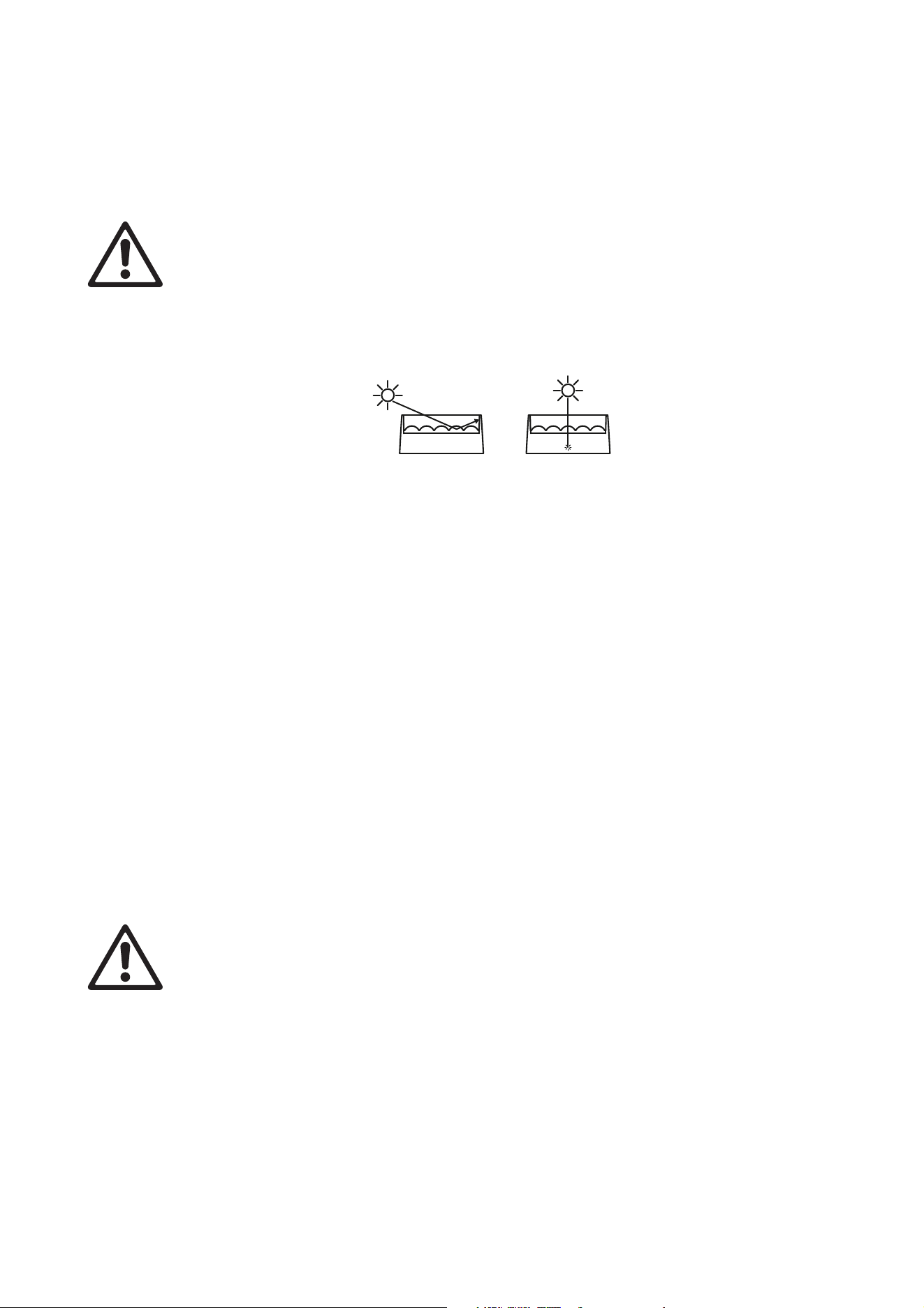
Warning! Do not expose the front glass to sunlight or other strong light sources.
See Figure 2. If light from the sun or other fixtures hits the front glass directly or at an angle, it can create a
fire risk and cause damage inside the fixture or around the edge of the front glass. Strong sunlight can
cause damage within seconds! Before the fixture is exposed to sunlight or strong light, shield the front glass
or point the fixture in the opposite direction to the light source.
Tilt adjustment
The Atomic 3000 LED mounting bracket lets you adjust and lock the fixture's tilt angle. To adjust tilt:
1. Loosen both tilt adjustment wheels (see ‘Fixture Overview’ on page 7) until the teeth in the tilt
adjustment locking mechanism disengage and you can tilt the fixture freely. If you can feel resistance
when you try to tilt the fixture, you have probably not loosened the wheels enough and you may damage
the teeth in the adjustment mechanism.
2. Adjust aiming, then retighten both wheels by hand. Tighten firmly but do not use tools to tighten, or you
may cause damage.
The first few times you adjust tilt, small particles of rubbed off paint or metal may become visible. This is not
a fault and it does not lead to any problems.
Fastening the fixture to a flat surface
The Atomic 3000 LED can be fastened to a stage or other flat surface.
Warning! The supporting surface must be hard and flat or air vents in the base may be blocked,
which will cause overheating. Fasten the fixture securely. Do not stand it on a surface or leave it
where it can be moved or can fall over.
To fasten the Atomic 3000 LED to a flat surface
1. Check that the surface can support at least six times the weight of all fixtures and equipment to be
installed on it.
2. Fasten the fixture’s mounting bracket to the surface using at least one M12 bolt, grade 8.8.
3. If the fixture may fall and cause injury or damage if the primary attachment fails, attach an approved
safety cable as described above.
Figure 2: Risk of sunlight damage
12
Atomic™ 3000 LED user manual
Mounting the fixture on a truss
The Atomic 3000 LED can be clamped to a truss or similar rigging structure in any orientation. When
mounting on a truss:
• Check that the rigging structure can support at least six times the weight of all fixtures and equipment to
be installed on it.
• Check that all rigging hardware is undamaged and rated for the weight it will secure.
• Block access under the work area.
• Work from a stable platform.
• Secure the fixture against rigging hardware failure with an approved safety cable.
Depending on the orientation of the fixture, you can use one of the following methods to mount the fixture on
a truss.
Truss-mount installation in any orientation
Warning! Do not use G-clamps, quick-trigger clamps or any other type of
clamp that does not completely encircle the supporting
structure when fastened, do not use an omega clamp and do
not use quarter-turn fasteners to attach rigging hardware
unless the fixture is hanging vertically in ‘free hanging mode’
as described below.
To suspend the fixture from a rigging structure such as a truss in any
orientation:
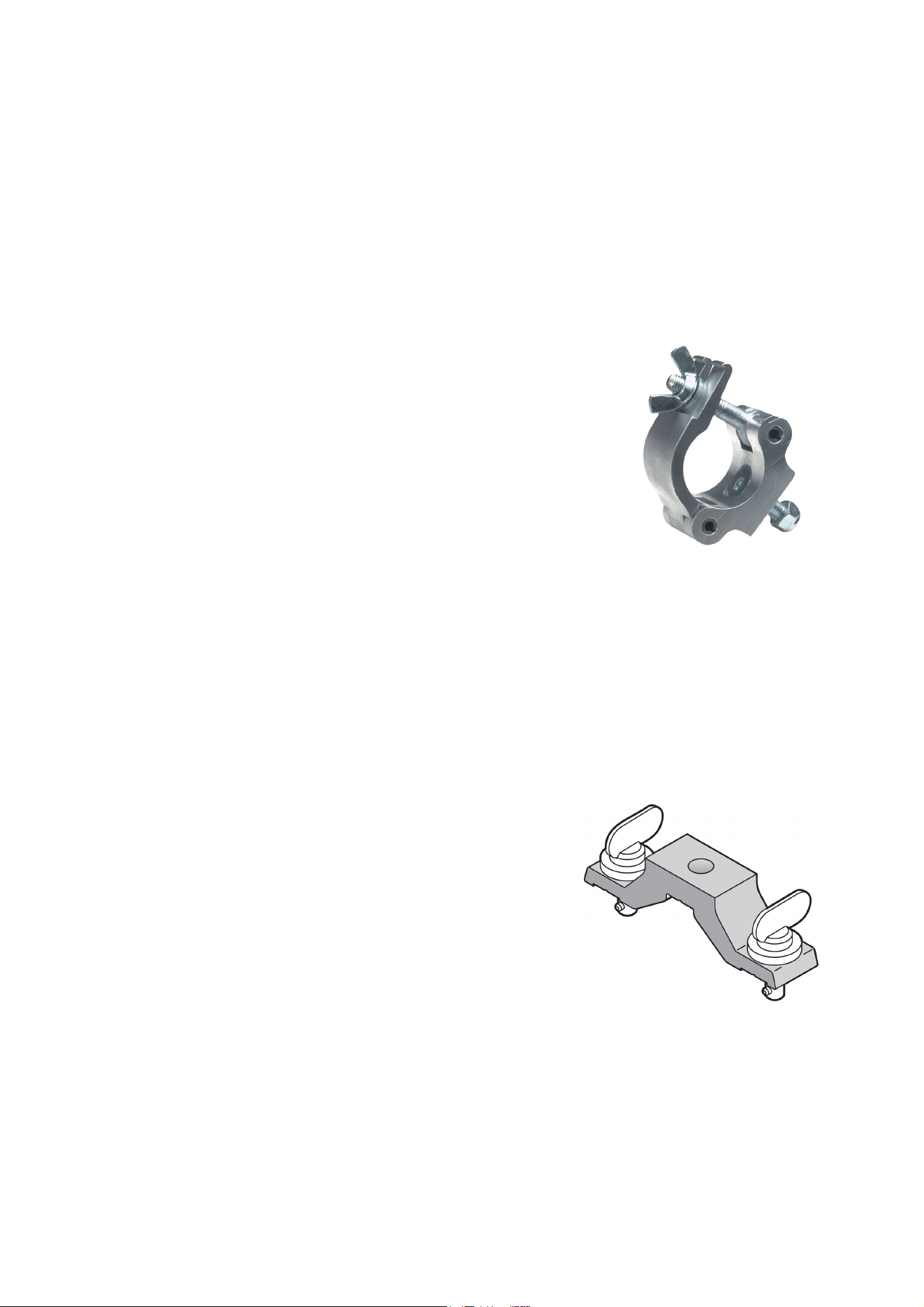
1. Fasten a half-coupler rigging clamp (see illustration on right) that
completely encircles the truss chord directly to the fixture’s
mounting bracket by means of an M12 grade 8.8 bolt passed
through the hole in the mounting bracket and secured with an
unworn self-locking nut. Do not use an omega bracket.
2. Block access under the work area. Working from a stable
platform, hang the fixture on the truss and fasten the half-coupler clamp around the truss chord.
3. If the fixture may fall and cause injury or damage if the primary attachment fails, attach an approved
safety cable to a secure anchoring point and to one of the safety cable attachment points on the fixture
(see Figure 1 on page 7).
4. If necessary, adjust the orientation of the fixture by loosening the tilt adjustment wheels (see Figure 1 on
page 7), adjusting the aim of the fixture and retightening the tilt adjustment wheels. Apply firm pressure
by hand only – do not use tools to tighten the tilt adjustment wheels.
Truss-mount installation hanging vertically in ‘free hanging mode’
It is possible to install the Atomic 3000 LED hanging vertically
downwards from a truss and then set it to the required tilt
using the tilt adjustment wheels in the mounting bracket. To
suspend the fixture from a rigging structure such as a truss
with the fixture hanging vertically in ‘free hanging mode’ only:
1. Bolt an approved, safe rigging clamp to a Martin Omega
Bracket, P/N 91602001 (see illustration on right) with an
M12 grade 8.8 bolt passed through the hole in the Omega
Bracket and secured with a self-locking nut that is in good
condition.
Figure 3: Half-coupler rigging
clamp
Figure 4: Omega bracket
Physical installation
13
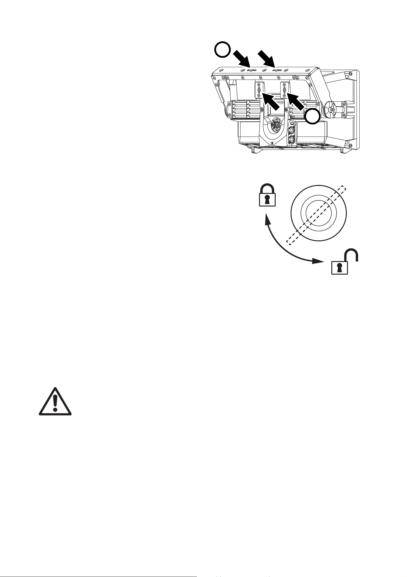
2. See Figure 5. Fasten the omega
bracket to the fixture’s mounting
bracket at A (or to the fixture housing
itself at B) with quarter-turn fasteners.
Fastening to the mounting bracket is
preferable, as this will let you adjust
the aim of the fixture.
3. See Figure 6. Make sure that
quarter-turn fasteners are turned a full
90° to the fully locked position.
4. Block access under the work area.
Working from a stable platform, hook
the clamp over the truss chord and
tighten the clamp enough to prevent
the fixture from falling off the truss but
leave the clamp loose enough for the
fixture to hang freely.
5. If you have fastened the omega
bracket to the fixture’s mounting bracket, adjust the
orientation of the fixture to obtain the desired aiming by
loosening the tilt adjustment wheels (see Figure 1 on page
7), adjusting the aim of the fixture and retightening the tilt
adjustment wheels.
6. Keeping the fixture in the position where it is now hanging
freely, tighten the rigging clamp completely so that the
fixture is fastened securely to the truss.
7. If the fixture can fall and cause injury or damage if the
primary attachment fails, attach an approved safety cable
to a secure anchoring point and to one of the fixture’s
safety cable attachment points on the fixture (see “Fixture
overview” on page 7).
8. If you need to adjust aiming further (and if you have
fastened the omega bracket to the fixture’s mounting
bracket), loosen the rigging clamp on the truss chord slightly, loosen both tilt adjustment wheels, adjust
the position of the fixture, retighten both wheels, applying firm hand pressure only, and then retighten the
rigging clamp on the truss chord with the fixture in the position where it hangs freely.
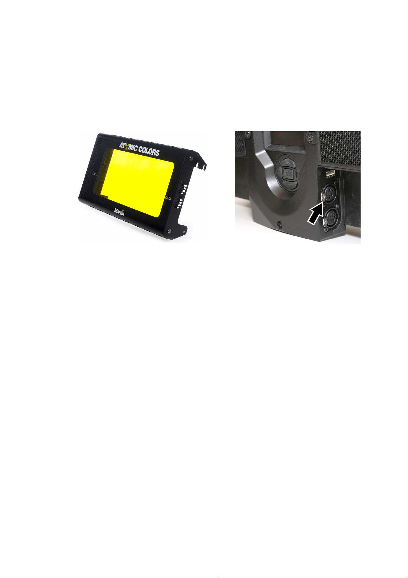
Atomic Colors scroller
A DMX-controlled gel scroller, the Atomic Colors, is available for the Atomic 3000 LED. Your Martin supplier
can give details. See Figure 7. The scroller installs on the front of the fixture and winds different colored gels
past the front of the fixture, adding color changing to the effects that can be controlled via DMX.
Warning! The Atomic 3000 LED has two safety cable attachment points (see Figure 1 on page 7).
Secure the Atomic Colors scroller against falling with a safety cable passed through the attachment
point on the right when viewed from the back of the fixture. Use the other attachment point for the
safety cable that secures the fixture.
Warning! Do not operate the Atomic 3000 LED with an Atomic Colors scroller in front of it unless the
scroller is correctly connected to the fixture. If an Atomic Colors is fastened to the front of an
Atomic 3000 LED but the power connection from the fixture to the scroller is interrupted or faulty,
the light and heat output from the Atomic 3000 LED can very quickly melt the gel in the scroller.
Do not use a Martin MP-2 or MP-8 external power supply unit to supply power to an Atomic Colors
scroller when you install the scroller on an Atomic 3000 LED.
Do not connect more than one Atomic Colors scroller to one Atomic 3000 LED. If you connect an
Atomic Colors to an Atomic 3000 LED, do not connect anything to the 4-pin XLR power and data
output connector of the Atomic Colors.
Every time you install an Atomic Colors scroller on an Atomic 3000 LED and any time you are in
doubt about whether there is a correct power connection between the two devices, check INFO →
COLOR SCROLLER → CONNECTED in the Atomic 3000 LED’s control panel. Only operate the fixture
Figure 5: Omega bracket fastening points
A
B
90°
Figure 6: Locking quarter-turn
fasteners
14
Atomic™ 3000 LED user manual
if the status here reads YES. If the status reads NO, check and rectify all connection problems
before you operate the fixture.
If you install an Atomic Colors scroller on an Atomic 3000 LED, select the following options in the
Atomic Colors control panel:
• Set Fan Speed
Fn to maximum: Fn4.
• Set Light-Activated Fan
LF to fans constantly on: LF0.
• Set the Gel Saver mode
GL to active: GL1.
To install an Atomic Colors scroller on the Atomic 3000 LED fixture:
1. See the Atomic Colors user manual for full installation details. This manual is available for download
from the Martin website at www.martin.com.
2. Fasten the Atomic Colors in position on the fixture following the physical installation instructions in the
Atomic Colors user manual. Do not over-tighten the retaining screws when fastening the Atomic Colors
to the fixture.
3. See Figure 7. Connect the Atomic Colors to the 4-pin XLR connector (arrowed) on the back of the fixture
to control the scroller and supply it with power. Do not use an external power supply with the Atomic
Colors, as this will prevent the Atomic 3000 LED from sensing that the Atomic Colors is present and
could cause damage to the colored gels. Use only the Atomic Colors scroller cable supplied by Martin to
connect an Atomic Colors to an Atomic 3000 LED. Do not use a cable that is longer than 5 m (16.4 ft.) in
length.
4. Fasten the carabiner clip on the Atomic Colors safety cable to the safety cable attachment point on the
right-hand side of the Atomic 3000 LED when looking at the back of the fixture. Make sure that the clip is
fully closed, repositioning the clip if necessary, so that the safety cable is secure.
5. As soon as you have installed the Atomic Colors on the Atomic 3000 LED, power the fixture on but do
not activate light output until you have completed the next three points.
6. Check the Atomic 3000 LED control panel for confirmation that the Atomic Colors is connected: INFO →
COLOR SCROLLER → CONNECTED must show YES. If it does not, check all connections, then check
the control panel again.
7. Set the following options in the Atomic Colors control panel:
• Set Fan Speed
Fn to maximum: Fn4.
• Set Light-Activated Fan LF to constant fan operation, not light-operated: LF0.
• Set Gel Saver mode
GL to active: GL1.
8. Check that you have DMX control of the Atomic Colors and that the gel string moves freely when you
change a color via DMX.
9. You can now activate the Atomic 3000 LED’s light output.
Figure 7: Atomic Colors
4-pin XLR connector for Atomic Colors
Setup
15
Setup
Warning! Read “Safety Information” on page 4 before installing, powering, operating or servicing
the Atomic 3000 LED.
Control panel and menu navigation
The onboard control panel and backlit graphic display on the back of the fixture are used to set the Atomic
3000 LED’s DMX address, configure individual fixture settings, read out data and execute service utilities.
See “Onboard control menus” on page 31 for a complete list of menus and commands.
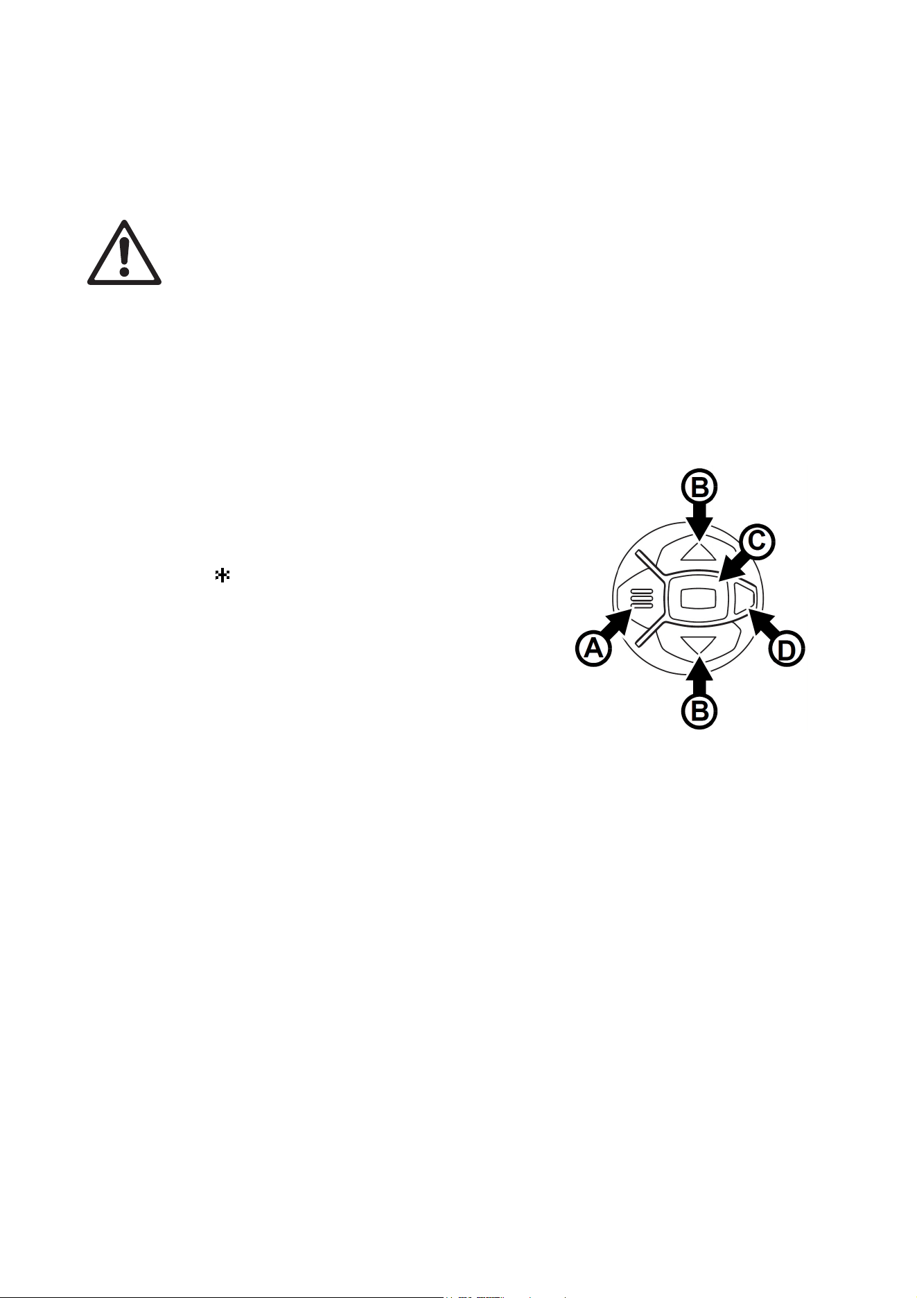
Using the control panel
• Press the MENU button A or Enter button C to access the
menus.
• Use the UP and DOWN buttons B to scroll up and down
menus.
• Press the ENTER button C to enter a menu or make a
selection.
• The currently selected item in a menu is indicated by a
star .
• Press the MENU button A to step backwards through the
menus.
Status LED
The LED D next to the control buttons indicates fixture
status:
• GREEN: All parameters normal. Constant green switches
off with the display if you have set the display to go into
sleep mode in the PERSONALITY menu.
• AMBER: Warning:.
-If ERROR MODE is set to Normal, the warning
message will be shown in the display.
-If ERROR MODE is set to Silent, you can display the error message by setting ERROR MODE to
NORMAL or by opening ERROR LIST in the SERVICE menu.
• RED: Error detected.
-If ERROR MODE is set to Normal, the error message will be shown in the display.
-If ERROR MODE is set to Silent, you can display the error message by setting ERROR MODE to
NORMAL or by opening ERROR LIST in the SERVICE menu.
Besides color, the status LED also gives the following information:
• FLASHING: No DMX signal detected.
• CONSTANT: Valid DMX signal detected (note: constant green only active if display is active).
Display panel
The DMX address is shown in the display panel when the Atomic 3000 LED is powered on and has reset.
The display can be set to go into sleep mode via
PERSONALITY → DISPLAY in the control menu.
Connecting a DMX signal ‘wakes up’ the display.
Figure 8: Control panel

16
Atomic™ 3000 LED user manual
Control panel shortcuts
Two shortcuts are available in the control panel before you enter the menus:
• Pressing and holding the MENU button for 2 seconds opens a shortcut menu that lets you reset the fixture
or rotate the display.
• Pressing the UP and DOWN arrows at the same time rotates the display through 180°.
DMX address setting
The DMX address, also known as the start channel, is the first channel used to receive instructions from the
controller. For independent control, each fixture must be assigned its own control channels. If two Atomic
3000 LED fixtures share the same address, they will behave identically. Address sharing can be useful for
diagnostic purposes and symmetric control.
The DMX address is configured using the
DMX ADDRESS menu in the control panel.
The highest address that you can select is automatically limited to make sure that enough channels are
available for the fixture – taking into account the mode that it is set to – within the 512 channels available in
one DMX universe.
DMX modes
The Atomic 3000 LED gives you a choice of DMX control modes in the CONTROL MODE menu. Your
choice of mode depends on how many features you want to control and how many DMX channels you have
available. “DMX protocol” on page 26 gives full details of the commands available in the different DMX
modes.
The modes available are:
3-channel DMX mode
3-channel mode offers control of the main effects of the Atomic 3000 LED only: high-power strobe on the
Beam LEDs with adjustable flash intensity, duration and rate.
You can obtain a continuous blinder effect by increasing both flash duration and flash rate until duration
exceeds the time available for a flash at the rate you set.
4-channel DMX mode
4-channel mode offers the same control as 3-channel mode plus basic pre-programmed effects: ramp
up/down, random strobe, a lightning effect and spikes.
Note that the 3-channel and 4-channel DMX modes in the Atomic 3000 LED are consistent with the DMX
modes in the original xenon-tube based Martin Atomic 3000 DMX™.
Extended DMX mode
Extended mode offers the same control as 4-channel mode plus control of the Aura LEDs. Both RGB color
control and color presets are available for the Aura. Electronic ‘shutter’ and strobe effects plus overall Aura
dimming control are also available.
Extended mode also includes a fixture control channel that allows fixture settings to be configured via DMX.
Finally, a range of pre-programmed FX is available. FX are effect sequences with adjustable parameters.
The sequences repeat in cycles and can be synchronized across multiple fixtures. A synchronization offset
can be set so that multiple fixtures start their effect sequences at specific points in the cycle.
Fixture ID
The Atomic 3000 LED lets you set a four-digit ID number to ease identification of the fixtures in an
installation. When a fixture is powered on for the first time, it displays its DMX address by default. As soon
as you set an ID number other than 0 in FIXTURE ID, the Atomic 3000 LED will display this ID number by
default, and indicate FIXTURE ID in the display.
Setup
17
Personality
The Atomic 3000 LED provides several options that let you optimize the fixture for different applications in
the PERSONALITY menu:
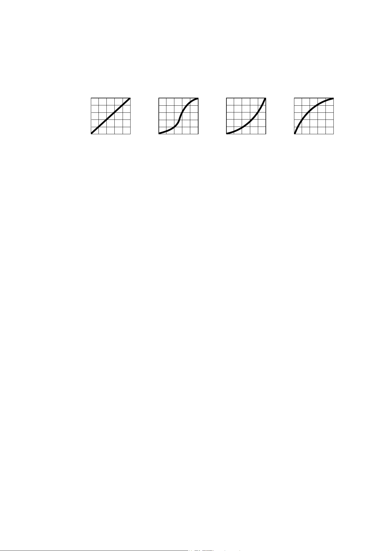
• DIMMER CURVE provides four dimming options that apply to both the Beam and the Aura light output
(see Figure 9):
- LINEAR – (optically linear) the increase in light intensity appears to be linear as DMX value is
increased.
- S-CURVE – light intensity control is finer at low levels and high levels and coarser at medium levels.
This curve emulates the RMS voltage dimming characteristics of an incandescent lamp such as the
tungsten halogen lamp of the Martin MAC TW1™.
- SQUARE LAW – light intensity control is finer at low levels and coarser at high levels.
- INV SQUARE LAW – light intensity control is coarser at low levels and finer at high levels.
• STROBE BEHAVIOR offers two options:
- LED gives constant light intensity during a flash or a continuous blinder effect. This gives more intense
output and provides an option for reducing flicker on video during a flash or blinder. Note that the
constant intensity obtained at the LED setting will only eliminate video flicker that results from intensity
variations within the duration of the light output. It will not affect video flicker that results from
interruptions in the light output. In other words, flicker may still be visible on video if you set strobe
flashes to a rate that produces interference between the flash rate and the video frame rate.
- XENON replicates the xenon lamp behavior of the original Martin Atomic 3000 DMX by applying a 50
Hz pulse to all light output. No matter how long a flash lasts, it will have this 50 Hz light output pulse.
• VIDEO TRACKING optimizes performance if the Atomic 3000 LED is used with a video source.
In normal use, the fixture processes the DMX signal it receives, tracking (or smoothing out) changes in
values in order to ensure smooth fading between colors and/or intensities. This signal processing takes
fractions of a second and is normally invisible, but if the fixture is used as a pixel in a video display (using
Martin P3™ video system components to convert video to DMX, for example) the processing can interfere
with video response times. If you enable video tracking, the fixture does not ‘smooth out’ DMX input but
instead snaps instantly when a DMX value changes.
For best results, we recommend that you enable video tracking during video display and disable it (the
default setting) during normal DMX control.
• DMX RESET defines whether the fixture or individual effects can be reset by sending a DMX command
on the fixture settings channel. Setting it to OFF can help you avoid accidentally sending a Reset
command during a show, for example.
• COOLING MODE lets you select between five cooling fan options depending on whether your priority is
highest light output or quietest cooling fan operation:
- REGULATE FANS optimizes cooling fan operation for light output. It controls fixture temperature by
varying cooling fan speed up to maximum level and will only limit light intensity if maximum cooling fan
speed is not enough to keep the fixture within its operating temperature limits.
- CONSTANT FAN ULOW / LOW / MEDIUM / HIGH sets the cooling fans to run at constant ultra-low,
low, medium or high speed. If necessary, output intensity is reduced so that the fixture stays within its
thermal limits at the cooling fan speed that is set.
If light output is reduced, the fixture may be reaching its operating temperature limits. To avoid this,
consider the following solutions:
Output
DMX %DMX %DMX %DMX %
Output
Output
Output
Linear S-curve Square law Inverse square law
Figure 9: Dimming curve options

18
Atomic™ 3000 LED user manual
- If the fixture is set to reduced cooling fan speed, increase the speed in the COOLING MODE menu.
- If necessary, clean the fixture, particularly the air vents.
- Check that there is sufficient airflow around the fixture. If possible, increase ventilation.
- If possible, provide reduced ambient temperature by moving the fixture away from sources of heat,
providing airflow from a cooler source of air, etc.
• DISPLAY offers four options:
- DISPLAY SLEEP lets you set whether the control panel display remains on permanently or whether it
goes into sleep mode 2, 5 or 10 minutes after the last time a control panel button is pressed.
- DISPLAY INTENSITY lets you adjust the brightness of the control panel display backlighting. You can
set the intensity to a level from 10% to 100%.
- DISPLAY ROTATION lets you rotate the display for easier reading depending on fixture orientation.
- DISPLAY CONTRAST lets you adjust the contrast of the control panel display for easiest reading in
different display backlighting and ambient light conditions.
• ERROR MODE enables or disables error warnings. If set to NORMAL, the display is activated and lights
up if the fixture needs to report an error. If set to SILENT, the fixture does not light the display with error
warnings but you can still read error messages by opening ERROR LIST in the SERVICE menu. In both
NORMAL and SILENT modes, the status LED lights amber to indicate a warning and red to indicate an
error.
Default and custom settings
The DEFAULT menu lets you reload the fixture’s factory default settings or save and recall up to three sets
of custom fixture settings. The savable settings comprise:
• all the settings in the PERSONALITY menu,
• the fixture’s DMX address, and
• the fixture’s DMX control mode.
Fixture information readouts
The following fixture information can be called up in the display:
• POWER ON TIME provides two counters:
- The TOTAL counter is not user-resettable and displays total hours powered on since manufacture.
- The RESETTABLE counter is user-resettable and displays the number of hours the fixture has been
powered on since the counter was last reset.
• POWER ON CYCLES also provides two counters:
- The TOTAL counter is not user-resettable and displays the total number of power on/off cycles since
manufacture.
- The RESETTABLE counter is user-resettable and displays the number of power on/off cycles since the
counter was last reset.
• COLOR SCROLLER lets you check whether the fixture has recognized that an Atomic Colors scroller has
been connected. If an Atomic Colors is fastened to the front of the fixture but not correctly connected to
the Atomic 3000 LED, starting the Atomic 3000 LED strobe can very quickly melt the gel string in the
Atomic Colors. Check the COLOR SCROLLER menu item immediately if you install an Atomic Colors
scroller. Also check it at any time if you are not 100% sure that the Atomic Colors is correctly connected.
• SW VERSION displays the currently installed firmware (fixture software) version.
• RDM UID displays the fixture’s factory-set unique ID for identification in RDM systems.
• FAN SPEEDS provides separate status readouts from the fixture’s cooling fans.
• TEMPERATURES provides separate PCB temperature readouts. If you display a readout and press
ENTER, you can choose to display the current temperature, the minimum or the maximum temperatures
since the last power cycle.

Setup
19
DMX signal monitoring
The Atomic 3000 LED provides data on the DMX signal it is receiving in the DMX LIVE menu. This
information can be useful for troubleshooting control problems.
RATE displays the DMX refresh rate in packets per second. Values lower than 10 or higher than 44 may
result in erratic performance, especially when using tracking control.
QUALITY displays the quality of the received DMX data as a percentage of packets received. Any value
below 100 indicates interference, poor connections, or other problems with the serial data link. Problems on
the data link are the most common cause of control difficulties.
START CODE displays the DMX start code. Packets with a start code other than 0 (and that are not RDM
data) may cause irregular performance.
The remaining options under DMX LIVE give a list of channels and display the DMX values in a range from
0 - 255 that are being received on each channel. The DMX channels displayed depend on which DMX mode
the fixture is set to.
Test sequences
TEST LEDS activates the fixture’s LEDs, allowing you to test them without a DMX controller. To run a test,
press the ENTER button to start. Press Menu to stop the test.
Manual control
The MANUAL CONTROL menu lets you reset the Atomic 3000 LED and operate the fixture without a DMX
controller.
RESET resets the fixture without cycling power off and on again.
To execute commands in the MANUAL CONTROL menu, scroll to the DMX channel that you want to
control, press the ENTER button and then select a value from 0 to 255. Press the ENTER button if you want
to hold the value or press the MENU button to exit without holding the value. The menu items and values
correspond to the commands listed in “DMX protocol” on page 26.

20
Atomic™ 3000 LED user manual
Operation and effects
Warning! Read “Safety Information” starting on page 4 before installing, powering, operating or
servicing the Atomic 3000 LED.
The Atomic 3000 LED can be controlled using a DMX control device. See “DMX protocol” on page 26 for a
full list of the channels and values required to control the different effects via DMX.
The fixture has two LED arrays:
• The Beam is a high-intensity array that gives powerful strobe and blinder effects
• The Aura gives RGB effects that light up the front of the fixture to complement or contrast with the output
from the Beam.
Strobe effects
The Atomic 3000 LED offers strobe effects from the Beam with variable flash rate, flash duration and
intensity. It also offers the following pre-programmed effects:
• Ramp up/down intensity modulation effects
• Random flashes
• Lightning – simulates the instantly recognizable ‘dirty’ flash of a lightning strike
• Spikes – low-intensity light output with high-intensity flashes.
Blinder effects
To obtain a continuous blinder effect, set flash duration to a long value and flash rate to a high frequency
value so that flashes ‘overlap’ and merge into continuous light output.
Aura RGB Color
Extended DMX mode gives control of the Aura. You can set Aura color with independent RGB control and
you can also control overall Aura intensity.
The four different dimming curve options available in the fixture’s control menus apply to both the Beam and
the Aura dimming curves.
Pre-programmed FX
Extended DMX mode gives access to a library of pre-programmed effects. These effects are simply called
FX in this manual and in the fixture menus.
See “FX: pre-programmed effects” on page 30 for an overview of the FX available. The Atomic 3000 LED
Product Support / Tech Docs page on www.martin.com features a downloadable detailed description of the
parameters adjusted and algorithms applied in the different FX.
You can select effects using the FX select DMX channel. You can modify speed (and sometimes other
parameters depending on the FX selected) using the FX adjust channel. In many FX, you can also use the
other DMX channels as input to generate further modification.
FX priority and overriding
If an FX is activated, it overrides any other settings for the parameters that the FX modifies. For example, an
FX that modifies the flash rate will override the rate set on the flash rate channel.
FX sync
If two or more fixtures are set to display the same FX (and if the FX consists of a repeating cycle), its start
point and duration can be synchronized in multiple fixtures by sending commands on the FX sync channel.
For synchronization to work, you must send the commands to all the fixtures at the same time.

Operation and effects
21
FX offset (synchronizing FX across multiple fixtures)
You can set fixtures so that they all start their FX cycle at the same time or you can shift any fixture’s FX
start time so that it displays its FX in sync with another fixture but with a time offset (delayed start).
Consider an FX cycle as consisting of 360° when you send an offset command on the FX sync channel. For
example:
• If you send a 180° offset command, the fixture will start its FX cycle halfway through the cycle of a fixture
that has 0° offset.
• If you set a line of fixtures on a DMX link to offsets of 0°, 10°, 20°, 30° etc. on the FX sync channel, you
will create an FX chase down the line of fixtures.
Beam color with the Atomic Colors scroller
To obtain colored strobe light from the Beam array, install the Martin Atomic Colors scroller unit on the
fixture (see “Atomic Colors scroller” on page 13).
Beam blackout after loss of data signal
To avoid possible difficulties stopping a strobe if data communication with the Atomic 3000 LED is
interrupted while the strobe is running, Beam output shuts down after 2 seconds if the DMX signal is lost.
RDM
RDM (Remote Device Management) is implemented in the Atomic 3000 LED, and RDM communication is
therefore possible over the DMX data link. As provided for in the ANSI/ESTA E1.20 RDM protocol, the
fixture can send information about its RDM-accessible parameters to an RDM control device.
22
Atomic™ 3000 LED user manual
Service and maintenance
Warning! Read “Safety Information” on page 4 before servicing the Atomic 3000 LED.
Warning! Disconnect the fixture from AC mains power and allow to cool for at least 10
minutes before handling. Be prepared for the fixture to light suddenly if connected to power.
Warning! Refer any service operation not described in this user manual to a qualified
service technician.
Important! Excessive dust, smoke fluid, and particle buildup degrades performance, causes
overheating and will damage the fixture. Damage caused by inadequate cleaning or maintenance is
not covered by the product warranty.
The user will need to clean the Atomic 3000 LED periodically, and it is also possible for the user to update
the fixture’s firmware. All other service operations on the Atomic 3000 LED must be carried out by Martin
Professional or its approved service agents.
Installation, on-site service and maintenance can be provided worldwide by the Martin Professional Global
Service organization and its approved agents, giving owners access to Martin’s expertise and product
knowledge in a partnership that will ensure the highest level of performance throughout the product’s
lifetime. Please contact your Martin supplier for details.
It is Martin policy to apply the strictest possible calibration procedures and use the best quality materials
available to ensure optimum performance and the longest possible component lifetimes. However, LEDs are
subject to wear and tear over the life of the product, resulting in gradual changes in color and overall
brightness over many thousands of hours of use. The extent of wear and tear depends heavily on operating
conditions and environment, so it is impossible to specify precisely whether and to what extent LED
performance will be affected. However, you may eventually need to ask Martin Professional to replace LEDs
if their characteristics are affected by wear and tear after an extended period of use and if you require
fixtures to perform within very precise optical and color parameters.
The manufacturer’s LED lifetime data is based on performance under the manufacturer’s test conditions. As
with all LEDs, the gradual reduction in luminous output will be accelerated when LEDs are used in a fixture,
where conditions are much tougher than in manufacturer’s testing. To maximize LED lifetimes, keep the
ambient temperature as low as possible and drive the LEDs no harder and for no longer than necessary.
Cleaning
Cleaning schedules for lighting fixtures vary greatly depending on the operating environment. It is therefore
impossible to specify precise cleaning intervals for the Atomic 3000 LED. Environmental factors that may
result in a need for frequent cleaning include:
• Use of smoke or fog machines.
• High airflow rates (near air conditioning vents, for example).
• Presence of cigarette smoke.
• Airborne dust (from stage effects, building structures and fittings or the natural environment at outdoor
events, for example).
If one or more of these factors is present, inspect fixtures within their first 100 hours of operation to see
whether cleaning is necessary. Check again at frequent intervals. This procedure will allow you to assess
cleaning requirements in your particular situation. If in doubt, consult your Martin dealer about a suitable
maintenance schedule.
Use gentle pressure only when cleaning, and work in a clean, well-lit area. Do not use any product that
contains solvents or abrasives, as these can cause surface damage.
Service and maintenance
23
Warning! Disconnect from power and allow to cool before cleaning.
To clean the fixture:
1. Disconnect the fixture from power and allow it to cool for at least 10 minutes.
2. Vacuum or gently blow away dust and loose particles from the outside of the fixture and the air vents at
the back and base with low-pressure compressed air. Do not direct compressed air or air suction at fans,
as this may damage them.
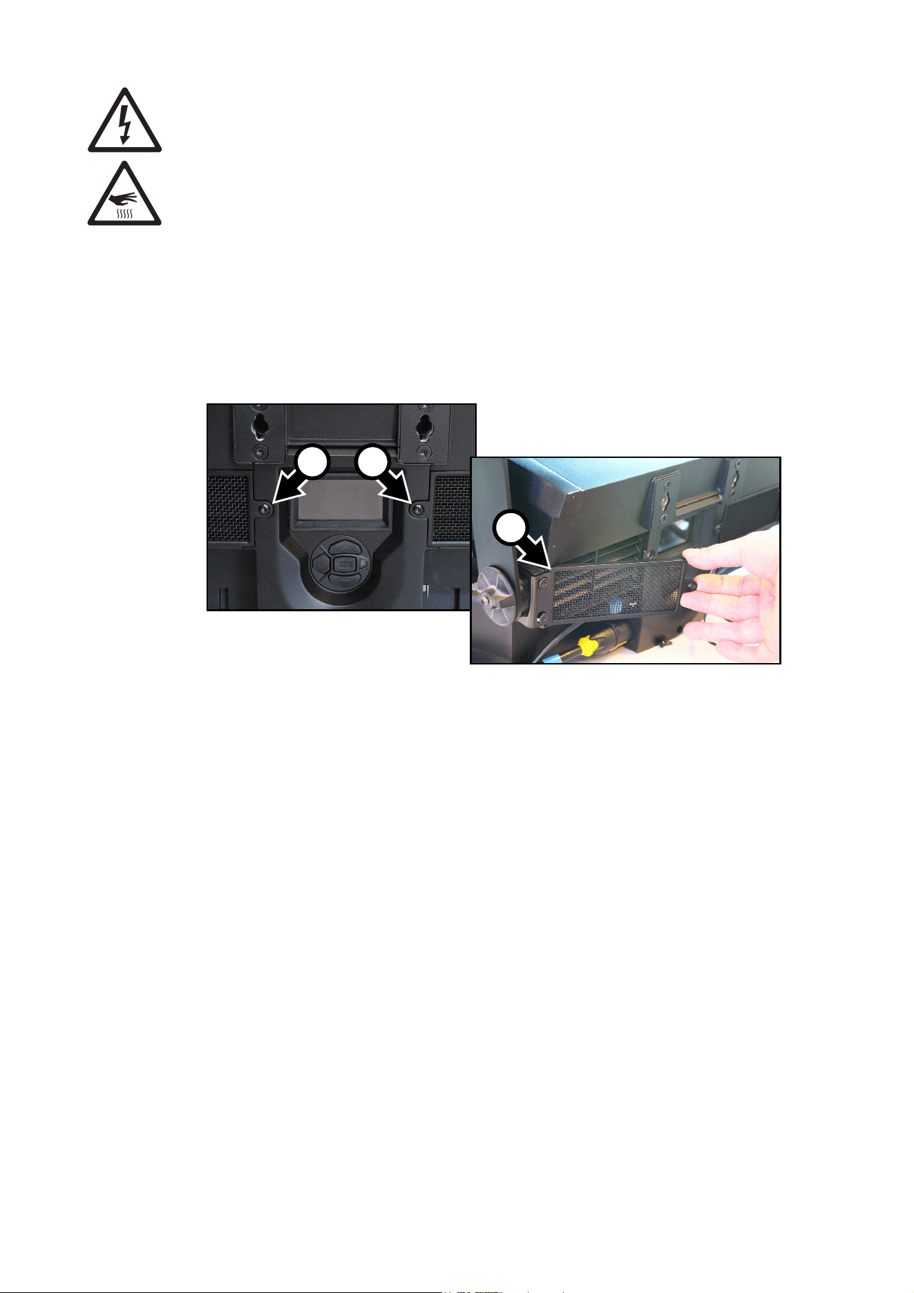
3. If the air grills on the back of the fixture are not perfectly clean, see Figure 10. Remove the air grill
retaining screws A, swing the grills out and remove the grills from the back of the fixture. Clean the grills
with a soft brush and vacuum cleaner. If there is any oily residue on the grills, clean them in a detergent
solution, then dry them thoroughly. Reinstall the grills by first hooking the outside edge B into the grill
aperture, then installing the screws A.
4. Clean the front glass by wiping gently with a soft, clean lint-free cloth moistened with a weak detergent
solution. Do not rub the surface hard: lift particles off with a soft repeated press. Dry with a soft, clean,
lint-free cloth or low-pressure compressed air. Remove stuck particles with an unscented tissue or
cotton swab moistened with glass cleaner or distilled water.
5. Check that the fixture is dry before reapplying power.
Control menu service utilities
The control panel SERVICE menu provides utilities for technicians rigging or servicing the fixture:
• ERROR LIST displays any error messages that are stored in internal memory.
• FAN CLEAN lets you set all cooling fans to run at maximum speed for a short period for cleaning
purposes.
• USB lets you update the fixture’s firmware using a USB memory device. For a detailed guide to updating
the firmware, see the next section in this chapter.
Firmware installation
The currently installed firmware version can be viewed in the control panel INFORMATION menu.
Firmware updates can be downloaded via the Martin Companion Application and can be installed using a
USB memory device or a Windows PC running the Martin Companion Application and a Martin Companion
Cable.
Fixture information and settings are not normally affected when you install new firmware, but check the
firmware release notes and any service notes for the firmware version in the Martin Companion Application.
These notes will give details if updating to the new firmware will affect settings. A firmware update can also
affect fixture behavior and DMX control. If necessary, a new DMX protocol will be available with the release
notes.
Do not switch the fixture off during a firmware update, or firmware may be corrupted.
Figure 10: Removing air grills
B
AA
24
Atomic™ 3000 LED user manual
Installing using a USB memory device
Important! Do not remove a USB memory device while the fixture is updating files.
The following are required in order to install firmware using a USB memory device:
• The Atomic 3000 LED firmware update file, available for download using the Martin Companion
application from the Martin website at http://www.martin.com.
• A USB memory device with the update file copied from a PC into the USB device’s root directory.
To install the Atomic 3000 LED firmware:
1. Download the .BANK (bank) firmware file using the
Martin Companion Application, and place this file
into the root directory of a USB memory device.
2. Read the firmware release notes carefully to check
for any instructions or warnings.
3. Disconnect the data link from the Atomic 3000 LED.
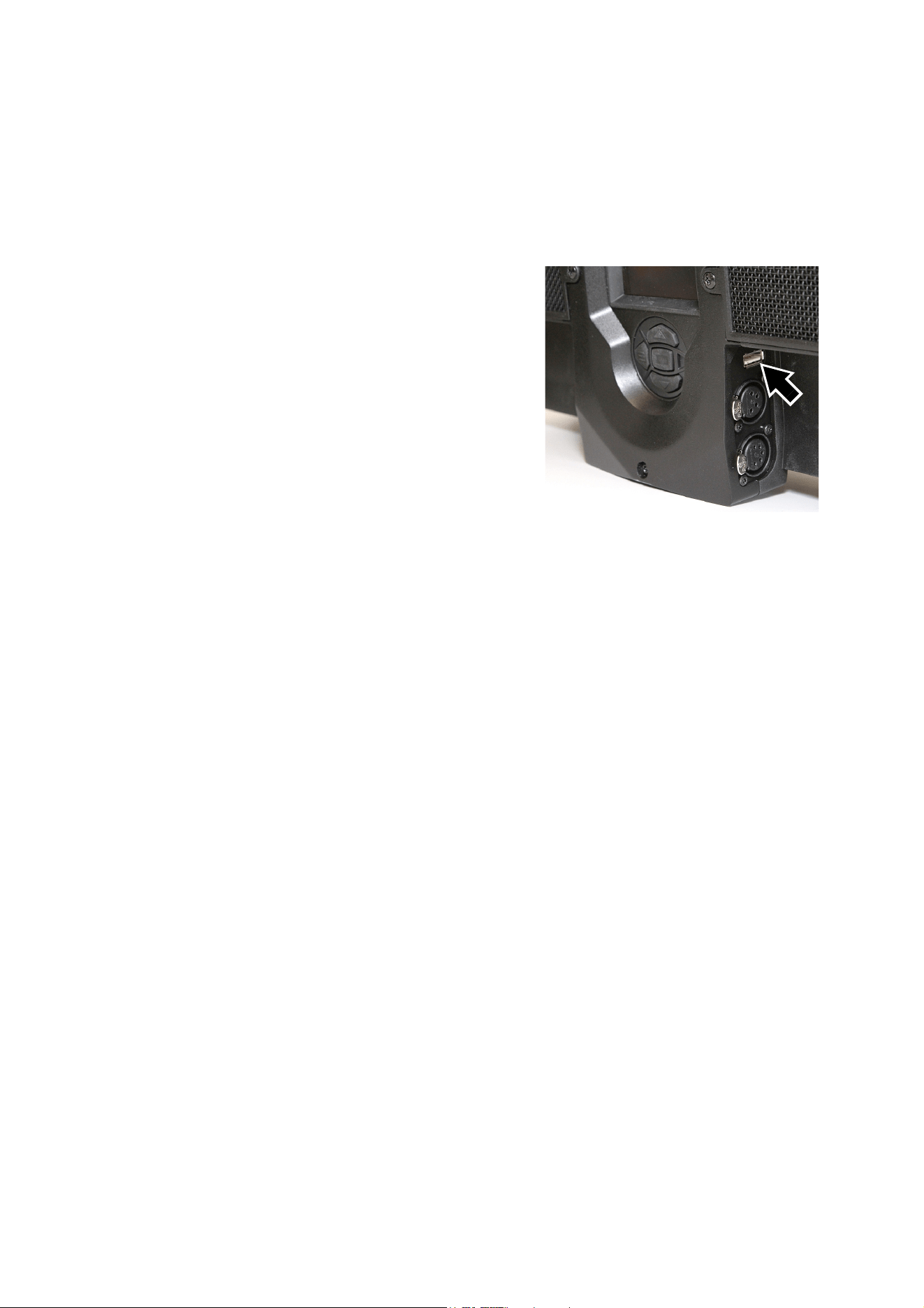
4. See Figure 11. Insert the USB memory device into
the Atomic 3000 LED’s USB host socket. The fixture
should recognize the USB device, illuminate the
display and show UPDATING FILE LIST in the
display while it checks and if necessary updates its
internal memory with any new firmware versions
stored on the USB device. If the fixture does not
recognize the USB device, scroll to the USB menu
under SERVICE in the control panel.
5. When the fixture has updated its internal memory,
AVAILABLE FIRMWARE will appear in the display.
You can now scroll through the firmware versions
available in memory.
6. To install a firmware version, select it by scrolling with the UP and DOWN buttons and then pressing
ENTER. The Atomic 3000 LED asks you to confirm installation of the new firmware. If you do not want to
install that version, press MENU.
7. Allow the fixture to install the firmware and reboot.
8. Remove the USB memory device. The newly-installed firmware version will now be displayed in the
INFORMATION menu.
9. Reconnect the data link.
10. Cycle power off and on. Check that the fixture resets correctly. If an error message appears in the
display, cycle power off and on again and check that the fixture now resets correctly.
11. If you have installed a new firmware version, check the Martin website at www.martin.com to see
whether an updated User Guide is available for the new firmware.
Installing using a PC and hardware interface
The following are required in order to install firmware using a PC:
• A Windows PC running the latest version of the Martin Companion application (available for download
free of charge from www.martin.com).
• The latest version of the Atomic 3000 LED firmware (downloaded automatically by the Martin Companion
Application).
• A Martin Companion Cable (available from your Martin supplier) to connect the Windows PC running the
Martin Companion Application to the fixture’s DMX port.
To install the Atomic 3000 LED firmware:
1. Launch the Martin Companion Application on a PC that is connected to the Internet and allow it to
synchronize with Martin’s online Fixture Firmware Database (this happens automatically when the
application is started).
2. In Martin Companion, find the latest Atomic 3000 LED firmware and select it.
3. Read the firmware release notes carefully to check for any instructions or warnings.
4. Press “Update Firmware via DMX” to start the upload procedure.
Figure 11: USB host socket

Service and maintenance
25
Fixture readouts
See also “Fixture information readouts” on page 18.
DMX input signal
The DMX LIVE menu lets you view the DMX values received on each channel in the mode it is currently set
to. If the fixture does not behave as expected, reading the DMX values can help you troubleshoot the
problem.
Fixture status
The Atomic 3000 LED gives fixture status readouts in the INFORMATION menu:
• Power on hours. You can view the number of hours since the resettable counter was last reset or the total
number of hours since manufacture. You can also reset the resettable counter to zero.
• Power cycles. You can view the number of times power has been cycled on and off since the resettable
counter was last reset or the total number of power cycles since manufacture. You can also reset the
resettable counter to zero.
• Color scroller connection. This readout lets you check whether an Atomic Colors scroller unit has been
correctly connected and recognized by the fixture.
• Current firmware version information.
• The fixture’s RDM ID number.
• Current fan speeds for each of the fixture’s cooling fans.
• Temperature readouts from the fixture’s PCBs. In each case, you can view the current temperature and
the maximum temperature reached since power was applied to the fixture.
Display messages
If an error occurs, the Atomic 3000 LED gives fixture status readouts in the display. See “Service and
display messages” on page 33.
26
Atomic™ 3000 LED user manual
DMX protocol
3-Channel DMX Mode
4-Channel DMX Mode
Channel
DMX
value Function
Fade
status
Default
value
1
0
1- 255
Beam flash intensity
Blackout
Minimum → maximum intensity
Snap 0
2
0 - 255
Beam flash duration
7→ 650 ms
Snap 0
3
0 - 255
Beam flash rate
0.289 → 16.67 Hz
Snap 0
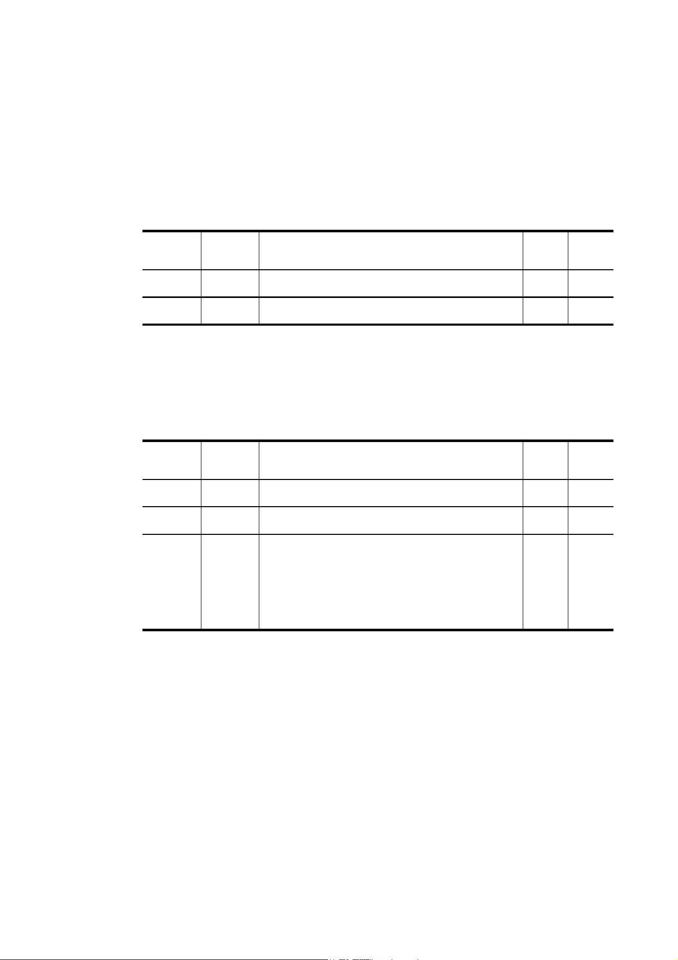
Table 2: DMX Protocol - 3 Channel Mode
Channel
DMX
value Function
Fade
status
Default
value
1
0
1- 255
Beam flash intensity
Blackout
Minimum → maximum intensity
Snap 0
2
0 - 255
Beam flash duration
7→ 650 ms
Snap 0
3
0 - 255
Beam flash rate
0.289 → 16.67 Hz
Snap 0
4
0 - 5
6 - 42
43 - 85
86 - 128
129 - 171
172 - 214
215 - 255
Beam special effects
No effect
Ramp up
Ramp down
Ramp up, down
Random
Lightning
Spikes (flash over low light)
Snap 0
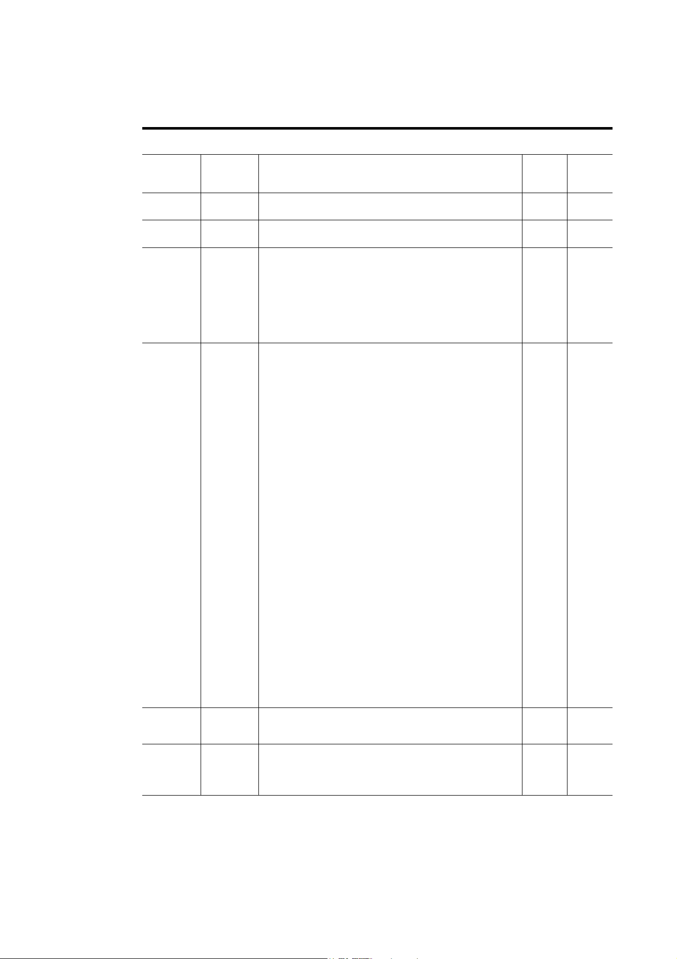
Table 3: DMX Protocol - 4 Channel Mode
DMX protocol
27
Extended DMX Mode
Channel
DMX
value Function
Fade
status
Default
value
Main control channels
1
0
1- 255
Beam flash intensity
Blackout
Minimum → maximum intensity
Snap 0
2
0 - 255
Beam flash duration
7→ 650 ms
Snap 0
3
0 - 255
Beam flash rate
Slow (0.289) → fast (16.67 Hz)
Snap 0
4
0 - 5
6 - 42
43 - 85
86 - 128
129 - 171
172 - 214
215 - 255
Beam special effects
No effect
Ramp up
Ramp down
Ramp up, down
Random
Lightning
Spikes (flash over low light)
Snap 0
5
0 - 9
10 - 14
15 - 22
23
24
25
26
27 - 35
36
37
38 - 51
52
53
54
55
56
57
58
59
60
61 - 255
Control / settings
No function
Reset entire fixture - 5 sec.
No function
Linear dimming curve - 1 sec. (menu override, setting
unaffected by power off/on)
Square law dimming curve - 1 sec. (menu override, factory
default setting, setting unaffected by power off/on)
Inverse square law dimming curve - 1 sec. (menu override,
setting unaffected by power off/on)
S-curve dimming curve - 1 sec. (menu override, setting
unaffected by power off/on)
No function
Enable video tracking
Disable video tracking
No function
Turn on control panel display - 1 sec.
Turn off control panel display - 1 sec.
Regulated fans speed, fixed light output intensity = full
(default setting, menu override, setting unaffected by power
off/on)
Fixed fan speed = full, regulated light output intensity
(menu override, setting unaffected by power off/on)
Fixed fan speed = medium, regulated light output intensity
(menu override, setting unaffected by power off/on)
Fixed fan speed = low, regulated light output intensity
(menu override, setting unaffected by power off/on)
Fixed fan speed = ultra low, regulated light output intensity
(menu override, setting unaffected by power off/on)
Strobe behavior = LED (menu override, setting unaffected by
power off/on)
Strobe behavior = Xenon (menu override, setting unaffected
by power off/on)
No function
Snap 0
6
0 - 255
FX select
Pre-programmed effect selection
(see “FX: pre-programmed effects” on page 30)
Snap 0
7
0 - 126
127 - 128
129-255
FX adjustment
Effect reversed fast → slow
Effect stops
Effect slow → fast
Fade 128
Table 4: DMX Protocol - Extended Mode
28
Atomic™ 3000 LED user manual
8
0
1
2
3
4
5
6
7
8
9
10
11
12
13
14
15
16
17
18
19
20
21
22
23
24
25
26
27
28
29
30
31
32
33
34
35
36
37 - 100
101 - 120
121 - 140
141 - 255
FX synchronization
No sync
Offset shift 10°
Offset shift 20°
Offset shift 30°
Offset shift 40°
Offset shift 50°
Offset shift 60°
Offset shift 70°
Offset shift 80°
Offset shift 90°
Offset shift 100°
Offset shift 110°
Offset shift 120°
Offset shift 130°
Offset shift 140°
Offset shift 150°
Offset shift 160°
Offset shift 170°
Offset shift 180°
Offset shift 190°
Offset shift 200°
Offset shift 210°
Offset shift 220°
Offset shift 230°
Offset shift 240°
Offset shift 250°
Offset shift 260°
Offset shift 270°
Offset shift 280°
Offset shift 290°
Offset shift 300°
Offset shift 310°
Offset shift 320°
Offset shift 330°
Offset shift 340°
Offset shift 350°
Synchronized: all fixtures start FX cycles at same time
No function
Random start
Random duration
No function
Snap 0
Aura control channels
9
0 - 19
20 - 49
50 - 200
201 - 210
211 - 255
Aura strobe/shutter effect
Shutter closed
Shutter open
Strobe, slow → fast
Shutter open
Random strobe, slow → fast
Snap 30
10
0 - 255
Aura dimmer
Closed → Open
Fade 0
11
0 - 255
Aura red
0% → 100%
Fade 255
12
0 - 255
Aura green
0% → 100%
Fade 255
13
0 - 255
Aura blue
0% → 100%
Fade 255
Channel
DMX
value Function
Fade
status
Default
value
Table 4: DMX Protocol - Extended Mode
DMX protocol
29
Note: DMX values labeled "No function" will have no effect - the last functional value will be used.
14
0 - 10
11 - 15
16 - 20
21 - 25
26 - 30
31 - 35
36 - 40
41 - 45
46 - 50
51 - 55
56 - 60
61 - 65
66 - 70
71 - 75
76 - 80
81 - 85
86 - 90
91 - 95
96 - 100
101 - 105
106 - 110
111 - 115
116 - 120
121 - 125
126 - 130
131 - 135
136 - 140
141 - 145
146 - 150
151 - 155
156 - 160
161 - 165
166 - 170
171 - 175
176 - 180
181 - 185
186 - 190
191 - 214
215 - 219
220 - 243
244 - 247
248 - 251
252 - 255
Aura color presets (‘color wheel’ effect)
Open. RGB color mixing enabled
Color 1 - LEE 790 - Moroccan pink
Color 2- LEE 157 - Pink
Color 3 - LEE 332 - Special rose pink
Color 4 - LEE 328 - Follies pink
Color 5 - LEE 345 - Fuchsia pink
Color 6 - LEE 194 - Surprise pink
Color 7 - LEE 181 - Congo Blue
Color 8 - LEE 071 - Tokyo Blue
Color 9 - LEE 120 - Deep Blue
Color 10 - LEE 079 - Just Blue
Color 11 - LEE 132 - Medium Blue
Color 12 - LEE 200 - Double CT Blue
Color 13 - LEE 161 - Slate Blue
Color 14 - LEE 201 - Full CT Blue
Color 15 - LEE 202 - Half CT Blue
Color 16 - LEE 117 - Steel Blue
Color 17 - LEE 353 - Lighter Blue
Color 18 - LEE 118 - Light Blue
Color 19 - LEE 116 - Medium Blue Green
Color 20 - LEE 124 - Dark Green
Color 21 - LEE 139 - Primary Green
Color 22 - LEE 089 - Moss Green
Color 23 - LEE 122 - Fern Green
Color 24 - LEE 738 - JAS Green
Color 25 - LEE 088 - Lime Green
Color 26 - LEE 100 - Spring Yellow
Color 27 - LEE 104 - Deep Amber
Color 28 - LEE 179 - Chrome Orange
Color 29 - LEE 105 - Orange
Color 30 - LEE 021 - Gold Amber
Color 31 - LEE 778 - Millennium Gold
Color 32 - LEE 135 - Deep Golden Amber
Color 33 - LEE 164 - Flame Red
Color 34 - Magenta
Color 35 - Medium Lavender
Color 36 - White
Aura ‘color wheel rotation’ effect
Clockwise, fast → slow
Stop (this will stop wherever the color is at the time)
Counter-clockwise, slow → fast
Aura random colors
Fast
Medium
Slow
Snap 0
Channel
DMX
value Function
Fade
status
Default
value
Table 4: DMX Protocol - Extended Mode
30
Atomic™ 3000 LED user manual
FX: pre-programmed effects
The table below lists the pre-programmed dynamic effects (macros) that can be controlled using DMX
channels 6 and 7 in Extended mode.
Select an effect on channel 6 by sending the value listed in the table. Adjust effect parameters such as
speed and intensity on channel 7, and adjust synchronization of effects across different fixtures on channel
8.
The dimmer channel will always control the intensity of the selected FX. Depending on which FX you select,
the FX will either modify or override certain parameters without affecting control of others. If you select an
RGB step, for example, it will override any values you are sending on the RGB channels, but the dimmer
channel will still control intensity.
Applicable when running Atomic 3000 LED firmware version 1.0.0.
Note: DMX values labeled "No function" will clear any effect currently running.
DMX
value
Effect DMX
value
Effect DMX
value
Effect
0
1
2
3
4-5
6
7
8-10
11
12
13
14-19
20
21-50
51
52-53
54
55
56
57
58
59-60
61
62
63
64-65
66
67
68
69-70
71
72
73
74-75
76
77
78
79-80
Beam effects
No function
Wave (sine wave)
Step (50/50 on/off)
Pulse
No function
Double strobe
Triple strobe
No function
Up, down, flash
Up, flash, down, flash
Random levels
No function
House light
No function
Aura effects
Aura pulse
No function
Aura ramp
No function
Rainbow wave
Rainbow step
Rainbow pulse
No function
RGB wave
RGB step
RGB pulse
No function
CMY wave
CMY step
CMY pulse
No function
Mix to white wave
Mix to white step
Mix to white pulse
No function
Random mix wave
Random mix step
Random mix pulse
No function
81
82-83
84
85
86-95
96
97
98
99
100
101
102
103
104
105
106-107
108
109
110-111
112
113
114-115
116
117
118
119
120
121
122-123
124
125
126
127-129
130
131
132
133
134
Random subtle wave
No function
Red white blue fade
Red white blue snaps
No function
Fire
Water
Ice
Hot and cold
Warm and fuzzy
Silver and gold
Gold and silver
No function
Circular chase slim
Circular chase wide
No function
Double circular chase slim
Double circular chase wide
No function
Vertical scroll
Horizontal scroll (L/R)
No function
Knight Rider slim
Knight Rider wide
Knight Rider slim with CW
surface
No function
4 segments scroll
6 segments scroll
No function
Police car 1
Police car 2
Police car 3
No function
Full bumps
Split bumps CW vertical
Split bumps CW horizontal
Random split bumps CW
vertical
Random split bumps CW
horizontal
135
136
137
138
139-143
144
145
146-150
151
152
153
154
155
156
157
158-160
161
162
163
164
165
166
167-255
Color shaker CW vertical
Color shaker CW horizontal
Color shaker CW vertical
and no black frame
Color shaker CW horizontal
and no black frame
No function
Swimming pool
Electric arc
No function
Combined effects
No function
Thunderstorm
Welding
3 Step strobe
Tick Tock
Aura ramp beam flash
Beam ramp aura flash
No function
Police Car 4
Police Car 5
Police Car 6
Police Car 7
Police Car 8
Police Car 9
No function
Table 5: FX in the Atomic 3000 LED
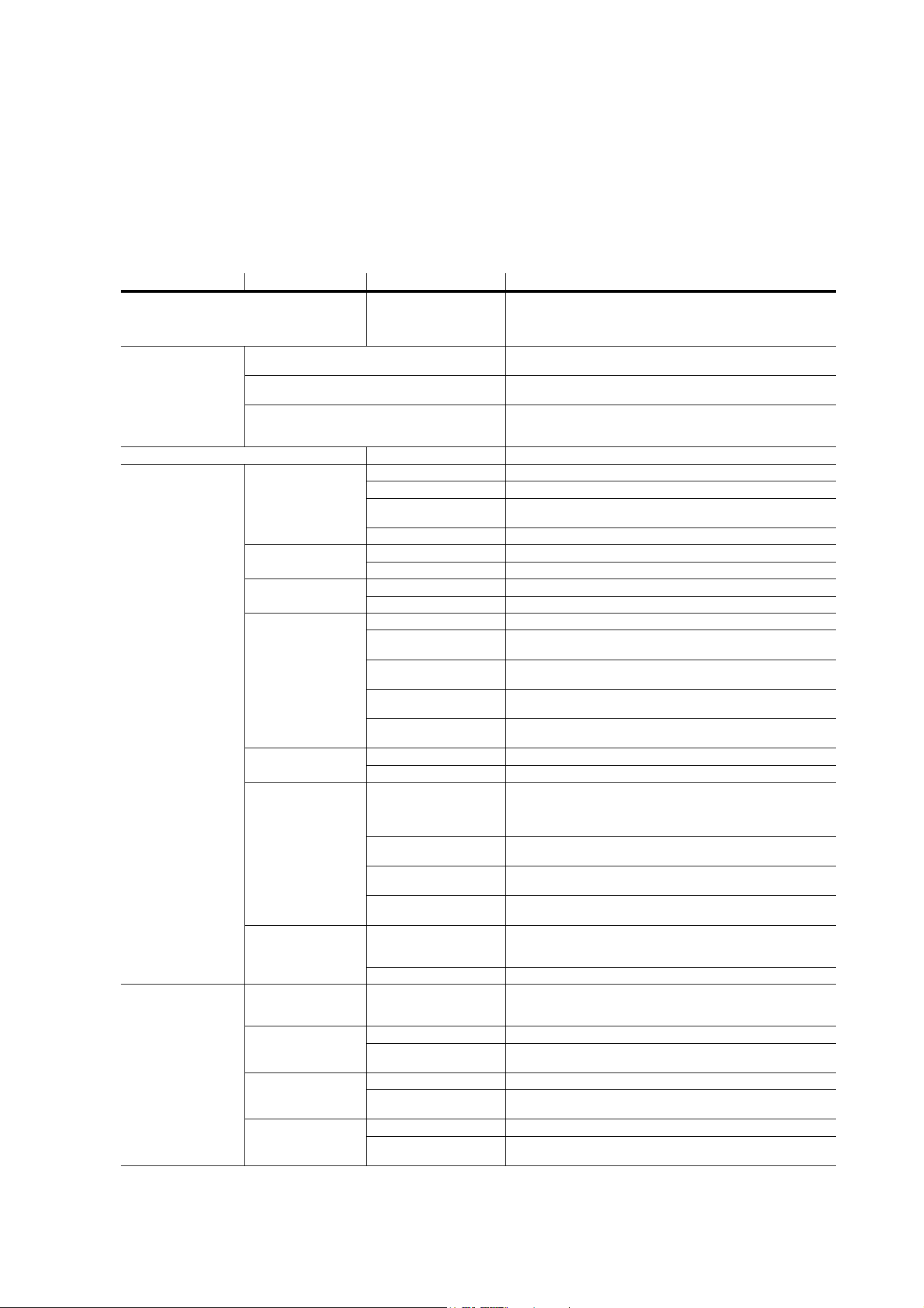
Onboard control menus
31
Onboard control menus
Default settings are indicated in bold print
Menu Item Options Notes
DMX ADDRESS 1 – XXX
DMX address (default address = 1). XXX means that the
DMX address range is limited so that the fixture will
always have enough DMX channels within the 512
available.
CONTROL
MODE
3 CHANNEL
Control of Beam strobe frequency, intensity and flash
duration.
4 CHANNEL
Control of Beam strobe frequency, intensity and flash
duration plus access to basic Beam effects.
EXTENDED
Control of Beam strobe frequency, intensity and
flash duration, basic Beam effects, RGB control of
Aura, fixture control/settings, pre-programmed FX.
FIXTURE ID 0 – 9999 User-definable fixture ID number.
PERSONALITY
DIMMER
CURVE
LINEAR Linear dimming curve
SQUARE LAW Square law dimming curve
INV SQUARE
LAW
Inverse square law dimming curve
S-CURVE S-curve dimming curve
STROBE
BEHAVIOR
LED Solid LED flash
XENON Flash simulates mains frequency cycles of a Xenon tube
VIDEO
TRACKING
ENABLED Color fading optimized for speed of changes
DISABLED Color fading optimized for smoothness
COOLING
MODE
REGULATE FANS Cooling fan speed thermostatically regulated
CONSTANT FAN
ULOW
Constant fan speed, ultra-low speed
CONSTANT FAN
LOW
Constant fan speed, low speed
CONSTANT FAN
MID
Constant fan speed, medium speed
CONSTANT FAN
HIGH
Constant fan speed, high speed
DMX RESET
OFF Disable reset via DMX
ON Enable reset via DMX
DISPLAY
DISPLAY SLEEP
ON / 2 MINUTES / 5 MINUTES / 10 MINUTES
Display remains on constantly / sleeps if no control
buttons pressed for 2, 5 or 10 minutes.
Default = 2 minutes.
DISPLAY
INTENSITY
Display intensity. Default=100%
DISPLAY
ROTATION
Display rotation NORMAL / 180°. Default= NORMAL
DISPLAY
CONTRAST
Display contrast 3% - 100%. Default=41%
ERROR MODE
NORMAL
Any errors detected are listed in display at 100%
intensity (regardless of DISPLAY INTENSITY
setting), status LED lights
SILENT Error messages not shown in display, status LED lights
DEFAULT
SETTINGS
FACTORY
DEFAULT
LOAD
Return all settings (except calibrations) to factory
defaults
NB: can take up to 2 minutes to complete!
CUSTOM 1
LOAD Load Custom Settings 1 from memory
SAVE
Save current fixture settings as Custom Settings 1
(overwrites existing Custom Settings 1)
CUSTOM 2
LOAD Load Custom Settings 2 from memory
SAVE
Save current fixture settings as Custom Settings 2
(overwrites existing Custom Settings 2)
CUSTOM 3
LOAD Load Custom Settings 3 from memory
SAVE
Save current fixture settings as Custom Settings 3
(overwrites existing Custom Settings 3)
Table 6: Control menu
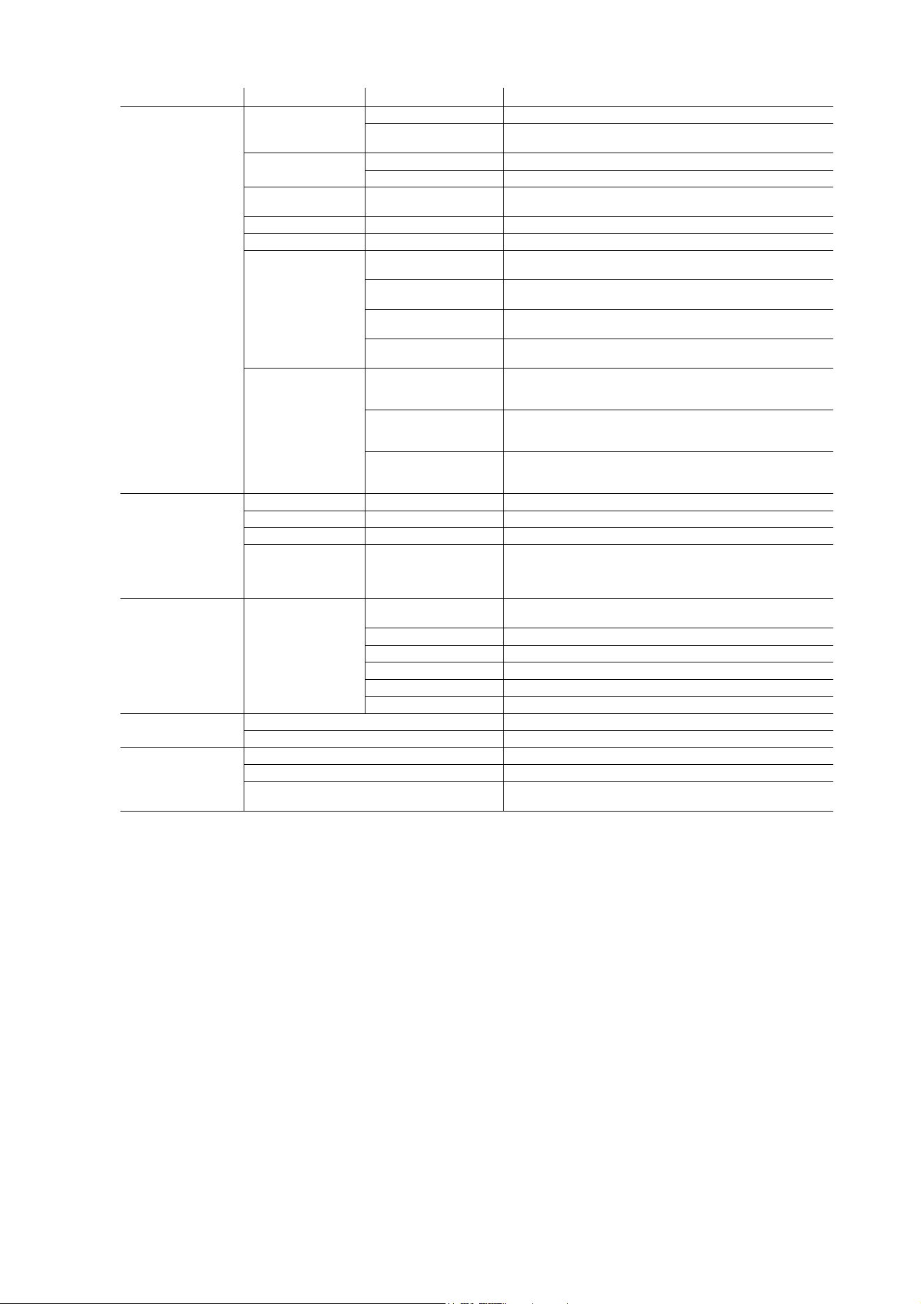
32
Atomic™ 3000 LED user manual
INFO
POWER ON
TIME
TOTAL X HOUR Display total hours of operation since manufacture
RESETTABLE X
HOUR
CLEAR COUNTER
→ YES/NO Reset counter to zero
POWER
CYCLES
TOTAL X Display total hours of operation since manufacture
RESETTABLE X CLEAR COUNTER
→ YES/NO Reset counter to zero
COLOR
SCROLLER
CONNECTED
YES/NO Display whether Atomic Colors scroller is
correctly connected
SW VERSION X.X.X Display current CPU firmware version
RDM UID 4D50:XXXXXXXX Display unique RDM ID
FAN SPEEDS
BASE FAN 1 X
RPM
Display current speed of base fan 1, NA, 0-10000 RPM
BASE FAN 2 X
RPM
Display current speed of base fan 2, NA, 0-10000 RPM
BASE FAN 3 X
RPM
Display current speed of base fan 3, NA, 0-10000 RPM
BASE FAN 4 X
RPM
Display current speed of base fan 4, NA, 0-10000 RPM
TEMPERATURES
USER INTERFACE
X C
CURRENT - MIN - MAX Display current, minimum or
maximum temperature in degrees Celsius since power
was last cycled off and on for user interface PCB
STROBE X C
CURRENT - MIN - MAX Display current, minimum or
maximum temperature in degrees Celsius since power
was last cycled off and on for strobe LEDs PCB
POWER UNIT X C
CURRENT - MIN - MAX Display current, minimum or
maximum temperature in degrees Celsius since power
was last cycled off and on for internal PSU
DMX LIVE
RATE XX Hz DMX transmission speed, live, in packets per second
QUALITY 0 - 100% Percentage of packets received with errors, live
STARTCODE 0 - 255 Decimal value of DMX start code, live
CHANNEL [Y]
X
[Y] 0 - 255
Scrolls through DMX value received on each DMX
channel:
[Y] = DMX channel number in current DMX control mode,
X = DMX value received on that channel
TEST TEST LEDS
BEAM STATIC
Beam LEDs activated at low intensity for inspection
purposes
BEAM OFF Beam LEDs blacked out
BEAM STROBE Test Beam LEDs only
RED AURA Test red Aura LEDs only
BLUE AURA Test blue Aura LEDs only
GREEN AURA Test green Aura LEDs only
MANUAL
CONTROL
RESET Reset fixture
CHANNEL [Y] X Send DMX value X on channel [Y]
SERVICE
ERROR LIST Displays any active errors
FAN CLEAN OFF/ON Stops and starts fan self-cleaning
USB
NO DEVICE / 1.x etc. Scrolls through valid firmware
versions found on memory device at USB port
Menu Item Options Notes
Table 6: Control menu

Service and display messages
33
Service and display messages
The Atomic 3000 LED gives service and maintenance information by displaying a large 3- or 4-character
short code and a smaller full-text message in the fixture’s display. The short code is visible at a distance,
allowing easier reading if the fixture is overhead in a rig, for example, while the full-text message gives more
detailed information.
Warning messages
Warning messages indicate that either:
• problems might appear in the future if no action is taken, or
• the user needs to pay special attention to a function or procedure when working with the fixture.
The Atomic 3000 LED communicates warnings as follows:
• Warning codes are shown continuously in the display and disappear when the user reacts to the warning.
• If more than one warning is detected, all warnings are displayed in sequence.
• If the display is inactive, the fixture’s status LED (see Figure 8 on page 15) flashes orange to indicate that
there is a warning. Activating the display will show the warning.
The possible warning messages are listed in Table 7 below
:
* High temperature warnings are canceled as soon as temperature returns to normal. If temperature
reaches cutoff level, the warning is replaced by a cutoff error message.
Short code
Long message and explanation
BANK
BANK NO ACCESS
Error unpacking firmware bank during/after firmware upload. Fixture will continue to operate on
existing firmware. Warning message is cleared by a successful firmware upload or at the next
power off/on cycle.
BETW
BEAM TEMP HIGH
Beam PCB sensor detects that normal operating temperature is exceeded.*
PUTW
PSU TEMP HIGH
Power supply unit PCB sensor detects that normal operating temperature is exceeded.*
SL W
SAFETY LOOP
A safety loop error occurred but is no longer active. Warning message is cleared at the next
power off/on cycle.
UITW
UI TEMP HIGH
Control panel PCB sensor detects that normal operating temperature is exceeded.*
Table 7: Warning messages

34
Atomic™ 3000 LED user manual
Error messages
Error messages indicate that there is a serious problem. The Atomic 3000 LED communicates errors as
follows:
• Error messages flash in the display.
• If more than one error is detected, the fixture flashes all errors three times each.
• Errors are shown in the display regardless of display status: they override an inactive display and any
other information that the display might be showing.
• If an error is present, the status LED flashes red.
The possible error messages are listed in Table 8 below
:
Short code
Long message and explanation
BETC
BEAM TMP CUTOFF
Beam PCB temperature too high. Beam shut down, fans set to max. Error message is cleared
when fixture is reset.
COLD
FIXTURE COLD
PCBs are below -20° C (-4° F). Effect operation may be abnormal or disabled due to cold.
FAN
BASE FAN 1 ERR
Base cooling fan 1 has stopped running. Error message is cleared when fixture is reset.
FAN
BASE FAN 2 ERR
Base cooling fan 2 has stopped running. Error message is cleared when fixture is reset.
FAN
BASE FAN 3 ERR
Base cooling fan 3 has stopped running. Error message is cleared when fixture is reset.
FAN
BASE FAN 4 ERR
Base cooling fan 4 has stopped running. Error message is cleared when fixture is reset.
PUTC
PSU TEMP CUT OFF
PSU temperature too high. Thermal cutoff activated. Light output is shut down, fans set to max.
Error message is cleared when fixture is reset.
PUTE
PSU TEMP SEN ERR
Error in PSU temperature sensor detected. Thermal cutoff activated. Light output is shut down.
Error message is cleared when sensor error is no longer detected.
SLER
SAFETY LOOP
Lamp safety loop circuit activated. Lamp temperature circuit breaker has cut lamp power. Circuit
breaker resets automatically after lamp temperature has returned to normal operating range.
UITC
UI TEMP CUT OFF
User interface PCB temperature too high. Thermal cutoff activated. Light output is shut down,
fans set to max. Error message is cleared when fixture is reset.
UITE
UI TEMP SEN ERR
Error in user interface temperature sensor detected. Thermal cutoff activated. Light output is
shut down. Error message is cleared when sensor error is no longer detected.
Table 8: Error messages
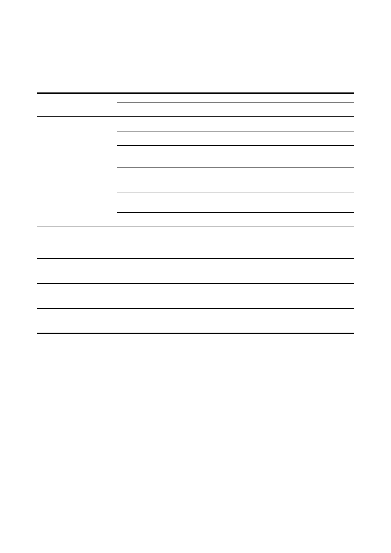
Troubleshooting
35
Troubleshooting
Problem Probable cause(s) Remedy
Fixture is completely dead.
No power to fixture. Check AC mains power and connections.
Internal circuit fault.
Have faulty fixture serviced by Martin service
technician.
One or more fixtures resets
correctly but responds
erratically or not at all to the
controller.
Fault on data link.
Inspect connections and cables. Correct poor
connections. Repair or replace damaged cables.
Data link not terminated.
Insert termination plug in output connector of the
last fixture on the link.
Incorrect fixture DMX addressing.
Check addressing on fixture and controller.
Check fixture profile on controller.
Check fixture is set to correct DMX mode.
One of the fixtures is defective and is
disturbing data transmission on the link.
Unplug XLR in and out connectors and connect
them directly together to bypass one fixture at a
time until normal operation is regained. Have faulty
fixture serviced by Martin service technician.
XLR pin-out on fixtures does not match (pins
2 and 3 reversed).
Install a phase-reversing cable between the fixtures
or swap pins 2 and 3 in the fixture that behaves
erratically.
DMX port exposed to electrostatic discharge
during installation.
Cycle power off and on.
Light output shuts down
unexpectedly.
Fixture is too hot.
Clean the fixture, especially air vents. Ensure free
airflow around fixture. Check that ambient
temperature does not exceed max. permitted level.
Switch to FULL cooling mode.
If problem persists, contact Martin for advice.
One or more color scrollers
move their gel strip without
receiving a command from the
controller.
Electronic switching noise from other
equipment.
Keep cables that carry data away from other
equipment. Keep cable runs to a minimum,
including cable that connects fixture to color
scroller.
One or more color scrollers
reset (gel strip scrolls to end
position and back to set position
within a few seconds).
Heavy load on mains branch circuit turned on
or off, causing surge that affects color scroller.
Give fixtures their own separate DMX universe
and/or mains branch circuit.
Use an optically isolated DMX splitter-amplifier.
MCB (Miniature Circuit Breaker)
trips and/or house lights flicker
during initial power on or in use.
Fixtures generating current peaks.
See AC power chapter in this manual and follow
recommendations for type of MCB and for
maximum permitted number of fixtures on each
mains branch circuit.
Table 9: Troubleshooting

36
Atomic™ 3000 LED user manual
Specifications
Physical
Length . . . . . . . . . . . . . . . . . . . . . . . . . . . . . . . . . . . . . . . . . . . . . . . . . . . . . . . . . . . . . . . . .245 mm (9.7 in.)
Width . . . . . . . . . . . . . . . . . . . . . . . . . . . . . . . . . . . . . . . . . . . . . . . . . . . . . . . . . . . . . . . . .425 mm (16.8 in.)
Height . . . . . . . . . . . . . . . . . . . . . . . . . . . . . . . . . . . . . . . . . . . . . . . . . . . . . . . . . . . . . . . . .240 mm (9.5 in.)
Weight . . . . . . . . . . . . . . . . . . . . . . . . . . . . . . . . . . . . . . . . . . . . . . . . . . . . . . . . . . . . . . . . 7.8 kg (17.2 lbs.)
All data includes the fixture’s mounting bracket
Dynamic Effects
Strobe . . . . . . . . . . . . . . . . . . . . . . . . . . . . . . 0.289 - 16.667 Hz, variable flash rate, intensity and duration
Special effects . . . . . . . . . . . .Blinder, ramp up/down, random flash, lightning. spikes, pre-programmed FX
Aura (secondary LED array illumination) color mixing . . . . . . . . . . . . . . . . . . . . . . . . . . . . . . . . . . . . . . RGB
Control and Programming
Control systems. . . . . . . . . . . . . . . . . . . . . . . . . . . . . . . . . . . . . . . . . . . . . . . . . . . . . . . . . . . . . .DMX, RDM
DMX channels . . . . . . . . . . . . . . . . . . . . . . . . . . . . . . . . . . . . . . . . . . . . . . . . . . . . . . . . . . . . . . . . . . .3/4/14
Setting and addressing . . . . . . . . . . . . . . . . . . . . . Control panel with backlit monochrome graphic display
DMX compliance . . . . . . . . . . . . . . . . . . . . . . . . . . . . . . . . . . . . . . . . . . . . . . . . . . . . . . . USITT DMX512-A
RDM compliance . . . . . . . . . . . . . . . . . . . . . . . . . . . . . . . . . . . . . . . . . . . . . . . . . . .ANSI/ESTA E1.20 RDM
Transceiver. . . . . . . . . . . . . . . . . . . . . . . . . . . . . . . . . . . . . . . . . . . . . . . . . . . . . . . . . Isolated/SELV RS-485
Firmware update . . . . . . . . . . . . . . . . . . . . . . . USB memory key or via DMX with Martin M-DMX interface
Construction
Color . . . . . . . . . . . . . . . . . . . . . . . . . . . . . . . . . . . . . . . . . . . . . . . . . . . . . . . . . . . . . . . . . . . . . . . . . . Black
Housing . . . . . . . . . . . . . . . . . . . . . . . . . . . Steel. high-impact thermoplastic, flame-retardant to UL 94 5VA
Protection rating. . . . . . . . . . . . . . . . . . . . . . . . . . . . . . . . . . . . . . . . . . . . . . . . . . . . . . . . . . . . . . . . . . .IP 20
Installation
Mounting points . . . . . . . . . . . . .Two pairs of quarter-turn fastener points, M12 holes in adjustable bracket
Orientation . . . . . . . . . . . . . . . . . . . . . . . . . . . . . . . . . . . . . . . . . . . . . . . . . . . . . . . . . . . . . . . . . . . . . . . .Any
Minimum distance to combustible materials . . . . . . . . . . . . . . . . . . . . . . . . . . . . . 20 cm (8 in.) from fixture
Minimum distance to illuminated surfaces . . . . . . . . . . . . . . . . . . . . . . . . . . . . . .1 m (3 ft. 4 in.) from fixture
Location . . . . . . . . . . . . . . . . . . . . . . . . . . . . . . . . Indoor use only, must be fastened to structure or surface
Connections
AC power in . . . . . . . . . . . . . . . . . . . . . . . . . . . . . . . . . . . . . . Neutrik PowerCON TRUE1 TOP male socket
DMX data in/out . . . . . . . . . . . . . . . . . . . . . . . . . . . . . . . . . . . . . . . . . . . . . . . . . . . . . . . . .5-pin locking XLR
Atomic Colors color gel scroller . . . . . . . . . . . . . . . . . . . . . . . . . . . . . . . . . . . . . . . . . . . . .4-pin locking XLR
Firmware upload . . . . . . . . . . . . . . . . . . . . . . . . . . . . . . . . . . . . . . . . . . . . . . . . . . . . . . . . . . . . . . . USB 2.0
Electrical
AC power . . . . . . . . . . . . . . . . . . . . . . . . . . . . . . . . . . . . . . . . . . . . . . . . . . . 100-240 V~ nominal, 50/60 Hz
Power supply unit. . . . . . . . . . . . . . . . . . . . . . . . . . . . . . . . . . . . . . . . . Auto-ranging electronic switch mode
Maximum power consumption . . . . . . . . . . . . . . . . . . . . . . . . . . . . . . . . . . . . . . . . . . . . . . . . . . . . . . .740 W
Power consumption, zero light output . . . . . . . . . . . . . . . . . . . . . . . . . . . . . . . . . . . . . . . . . . . . . . . . .<25 W
Rated current consumption . . . . . . . . . . . . . . . . . . . . . . . . . . . . . . . . . . . . . . . . . . . . . . . . . . . . . 3.9 - 8.4 A
Peak current consumption . . . . . . . . . . . . . . . . . . . . . . . . . . . . . . . . . . . . . . . . . . . . . . . . . . . . . . . . . .17.7 A
Typical half-cycle RMS inrush current . . . . . . . . . . . . . . . . . . . . . . . . . . . . . . . . . . . . . . . . . . . . . . . . .17.7 A
Typical earth-leakage current. . . . . . . . . . . . . . . . . . . . . . . . . . . . . . . . . . . . . . . . . . . . . . . . . . . . . . .0.18mA
Specifications
37
Typical Power and Current
100 V, 60 Hz. . . . . . . . . . . . . . . . . . . . . . . . . . . . . . . . . . . . . . . . . . . . . . . . . . . . . . . . 663 W, 6.8 A, PF 0.98
120 V, 60 Hz. . . . . . . . . . . . . . . . . . . . . . . . . . . . . . . . . . . . . . . . . . . . . . . . . . . . . . . . 655 W, 5.7 A, PF 0.96
208 V, 60 Hz. . . . . . . . . . . . . . . . . . . . . . . . . . . . . . . . . . . . . . . . . . . . . . . . . . . . . . . . 645 W, 3.5 A, PF 0.89
230 V, 50 Hz. . . . . . . . . . . . . . . . . . . . . . . . . . . . . . . . . . . . . . . . . . . . . . . . . . . . . . . . 642 W, 3.2 A, PF 0.88
240 V, 50 Hz. . . . . . . . . . . . . . . . . . . . . . . . . . . . . . . . . . . . . . . . . . . . . . . . . . . . . . . . 642 W, 3.1 A, PF 0.87
Measurements made at nominal voltage with all LEDs at full strobe intensity. Allow for a deviation of +/-
10%. Allow for peak currents that exceed these figures when using the blinder effect. PF = power factor.
Thermal
Cooling. . . . . . . . . . . . . . . . . . . .Forced air (temperature-regulated, low noise, user-definable fan settings)
Maximum ambient temperature (Ta max.) . . . . . . . . . . . . . . . . . . . . . . . . . . . . . . . . . . . . . . . 40° C (104° F)
Minimum ambient temperature (Ta min.) . . . . . . . . . . . . . . . . . . . . . . . . . . . . . . . . . . . . . . . . . . 5° C (41° F)
Typical total heat dissipation (calculated, +/- 10%) . . . . . . . . . . . . . . . . . . . . . . . . . . . . . . . . . 2270 BTU/hr.
Approvals
EU safety . . . . . . . . . . . . . . . . . . . . . . . . . . . . . . . . . . EN 60598-2-17 (EN 60598-1), EN 62471, EN 62493
EU EMC. . . . EN 55015 Class B, EN 61547, EN 55032, EN 55035, EN 61000-3-2 Class A, EN 61000-3-3
US safety . . . . . . . . . . . . . . . . . . . . . . . . . . . . . . . . . . . . . . . . . . . . . . . . . . . . . . . . . . . . . . . . . . . . . UL 1573
US EMC. . . . . . . . . . . . . . . . . . . . . . . . . . . . . . . . . . . . . . . . . . . . . . . . . . . . . . . . . . . . . 47 CFR 15 Class A
Canadian safety. . . . . . . . . . . . . . . . . . . . . . . . . . . . . . . . . . . . . . . . . . . . CSA E598-2-17 (CSA E60598-1)
Canadian EMC . . . . . . . . . . . . . . . . . . . . . . . . . . . . . . . . . . . . . . . . . . . . . . . . . . . . . . . . ICES-003 Class A
Australia/NZ . . . . . . . . . . . . . . . . . . . . . . . . . . . . . . . . . . . . . . . . . . . . . . . . . . . . . . . . . . . . . . . . . . . . . .RCM
United Kingdom . . . . . . . . . . . . . . . . . . . . . . . . . . . . . . . . . . . . . . . . . . . . . . . . . . . . . . . . . . . . . . . . . .UKCA
Accessories
Atomic Colors gel scroller . . . . . . . . . . . . . . . . . . . . . . . . . . . . . . . . . . . . . . . . . . . . . . . . . . . P/N 91611086
Power connectors
Cable Connector, Neutrik PowerCON TRUE1 TOP NAC3FX-W (female) . . . . . . . . . . . . .P/N 91611789HU
Power cables
Power Input Cable, H07RN-F, 2.5 mm2, bare ends to
TRUE1 TOP NAC3FX-W (female), 1.5 m (4.9 ft.). . . . . . . . . . . . . . . . . . . . . . . . . . . . . . . . P/N 91611797
Power Input Cable, H07RN-F, 2.5 mm2, bare ends to
TRUE1 TOP NAC3FX-W (female), 5 m (16.4 ft.) . . . . . . . . . . . . . . . . . . . . . . . . . . . . . . . . P/N 91611786
Power Input Cable, SJOOW, 12 AWG, bare ends to
TRUE1 TOP NAC3FX-W (female), 1.5 m (4.9 ft.). . . . . . . . . . . . . . . . . . . . . . . . . . . . . . . . P/N 91610173
Power Input Cable, SJOOW, 12 AWG, bare ends to
TRUE1 TOP NAC3FX-W (female), 5 m (16.4 ft.) . . . . . . . . . . . . . . . . . . . . . . . . . . . . . . . . P/N 91610174
Installation hardware
Half-coupler clamp. . . . . . . . . . . . . . . . . . . . . . . . . . . . . . . . . . . . . . . . . . . . . . . . . . . . . . . . . P/N 91602005
G-clamp (vertical hanging installation only). . . . . . . . . . . . . . . . . . . . . . . . . . . . . . . . . . . . . . P/N 91602003
Quick trigger clamp (vertical hanging installation only) . . . . . . . . . . . . . . . . . . . . . . . . . . . . . P/N 91602007
Safety Cable, SWL 60 kg, BGV C1 / DGUV 17, black . . . . . . . . . . . . . . . . . . . . . . . . . . . . . . P/N 91604006
Safety Cable, SWL 60 kg, BGV C1 / DGUV 17, silver . . . . . . . . . . . . . . . . . . . . . . . . . . . . . . P/N 91604007
Related Items
Martin® Companion software suite (incl. firmware uploader) . . . . . . Free download from www.martin.com
Martin® Companion Cable USB/DMX hardware interface . . . . . . . . . . . . . . . . . . . . . . . . . . P/N 91616091
Ordering Information
Atomic 3000™ LED in cardboard box . . . . . . . . . . . . . . . . . . . . . . . . . . . . . . . . . . . . . . . . . . P/N 90425000
Specifications subject to change without notice. For the latest product specifications, see www.martin.com
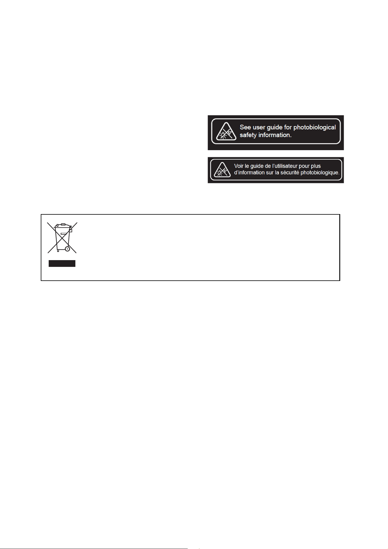
38
Atomic™ 3000 LED user manual
FCC Compliance
This equipment has been tested and found to comply with the limits for a Class A digital device, pursuant to part 15 of the FCC Rules.
These limits are designed to provide reasonable protection against harmful interference when the equipment is operated in a commercial
environment. This equipment generates, uses and can radiate radio frequency energy and, if not installed and used in accordance with
the instructions, may cause harmful interference to radio communications. Operation of this equipment in a residential area is likely to
cause harmful interference, in which case the user will be required to correct the interference at his own expense.
Canadian Interference-Causing Equipment Regulations - Règlement sur le Matériel Brouilleur du Canada
This Class A digital apparatus meets all requirements of the Canadian Interference-Causing Equipment Regulations.
Cet appareil numérique de la classe A respecte toutes les exigences du Règlement sur le Matériel Brouilleur du Canada.
Photobiological Safety Warning
The labels shown on the right are displayed on this product. If a label
becomes difficult or impossible to read, it must be replaced using the
illustration on the left to reproduce a new label.
Disposing of this product
Martin products are supplied in compliance with Directive 2012/19/EC of the European Parliament and of
the Council of the European Union on WEEE (Waste Electrical and Electronic Equipment), where
applicable.
Help preserve the environment! Ensure that this product is recycled at the end of its life. Your supplier can
give details of local arrangements for the disposal of Martin products.


www.martin.com