EN
61820
PROBE
AUTO
Original Instructions
Version 2 – January 2026

– 2 –
User Manual for: Auto Probe
Stock Nos: 61820
Part Nos: AP1
Version 1: January 2021
First release
Version 2: January 2026
1. Intended Use
This product is designed as a diagnostic tool for
automotive electrical systems. The following tests can be
carried out on vehicle electrical systems from 6V up to
24V: Polarity test, powering up components, continuity
tests, short circuit detection and bad earth tracing.
Any other application beyond the conditions established
for use will be considered misuse. Draper Tools accepts
no responsibility for improper use of this product.
Read this manual in full before using this product and
retain it for future use. Always use the latest version of
the manual. Please visit drapertools.com/manuals for
the latest version.
2. Specication
Stock No. 61820
Part No. AP1
Rated Voltage 6 – 24V DC
Overload protection 8A
Probe length 68mm
Net Weight 340g
Cord Length (approx:) 3.45M
3. Health and Safety Information
Important: Read all the Health and Safety instructions before attempting to operate, maintain or repair this product.
Failure to follow these instructions may result in injury or damage to the user or the product.
• DO NOT use the probe around explosive gases,
vapours or dust. When the probe is switched on,
current is conducted directly to the tip which may
cause a spark when contacting ground or certain
circuits.
• The probe is only suitable for use with 6 – 24V DC
systems. DO NOT use with 110/220V house current.
• DO NOT use on AC voltage.
• After checks are completed on your vehicle ensure the
disconnected connections are correctly restored.
• ALWAYS follow the instructions and procedures
indicated in the vehicle’s manual before
disconnecting any part of its electrical circuit.
• Take care when using the probe to perform any
measurement. NEVER touch any dangerous parts of
the vehicle with your hands. DO NOT touch any live
conductors.
• DO NOT use the probe if the casing, cable or probe tip
are damaged.
• DO NOT use the probe if the vehicle is being driven.
• Some vehicles components work on a lower voltage
and are not suitable for use with this probe voltage
range. To avoid damage, DO NOT use this probe to
apply voltage directly or indirectly to them.
• Before you drive the vehicle ensure that it is safe
and reliable.
– 3 –
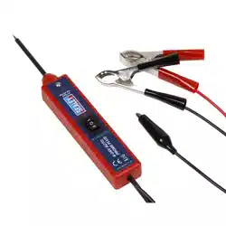
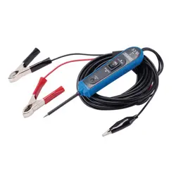
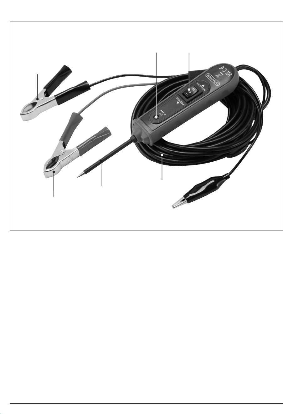
(1) Red positive (+) spring clip
(2) Black negative (-) spring clip
(3) Probe
(4) LED indicator
(5) ON/OFF power switch
(6) Auxiliary ground lead
Please visit drapertools.com for our full range of accessories and consumables.
4. Identication
(5)(4)
(2)
(6)
(3)
(1)
– 4 –
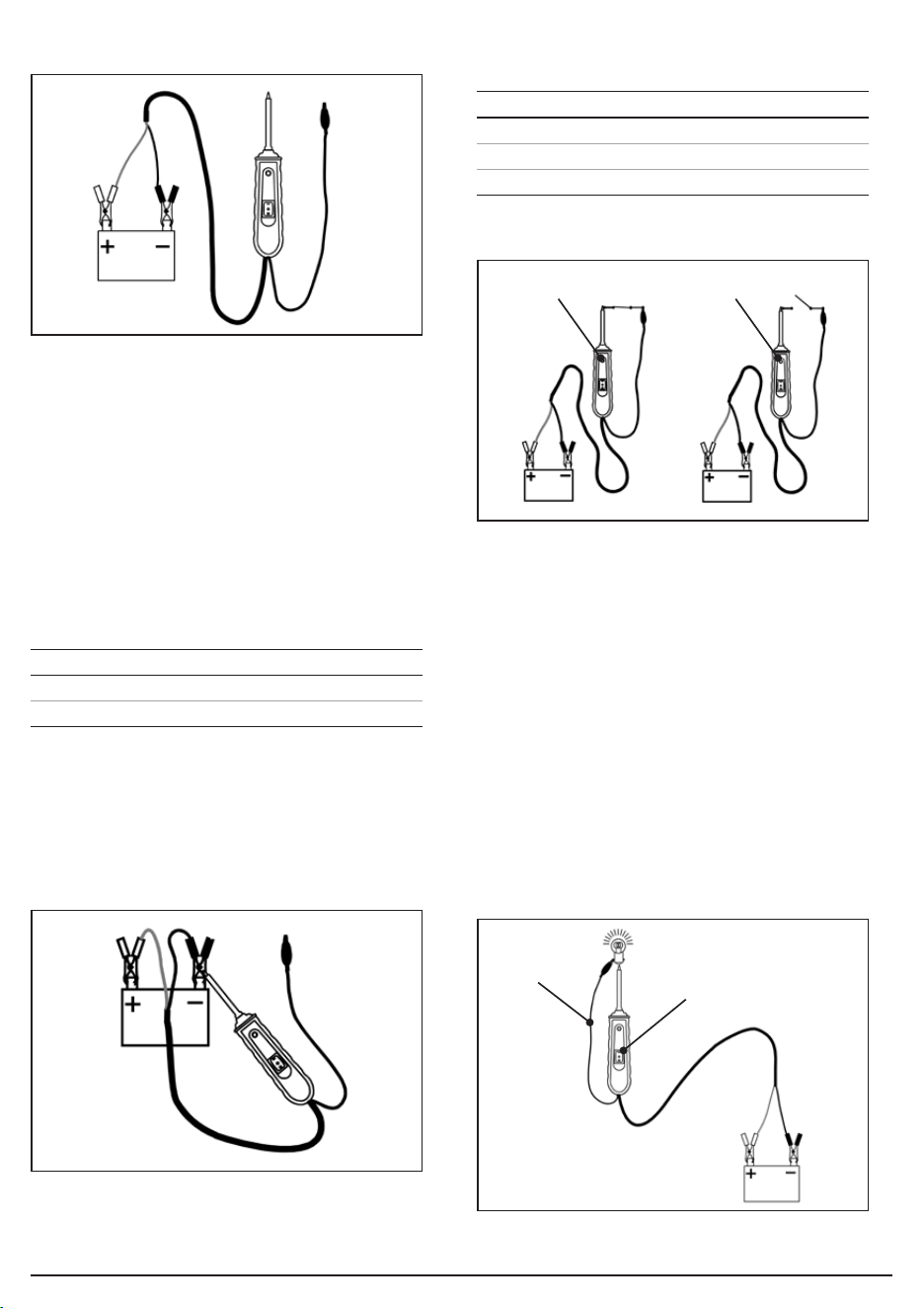
5. Preparing the Auto Probe (Fig.1)
• Unwind the Auto probe’s auxiliary ground lead (6).
• Clamp the red clip to the positive terminal of the
vehicle’s battery.
• Clamp the black clip to the negative terminal of the
vehicle’s battery.
6. Operating the Auto Probe
6.1 Self-Testing Mode
• Press the ON/OFF switch (5):
• The Auto probe is now ready to use.
• If the LED indicator (4) does not light up, the clips are
either not connected correctly, or the device is
damaged.
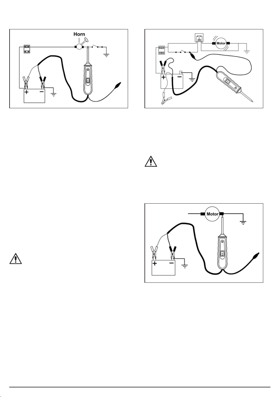
6.2 Polarity Testing (Fig.2)
• Contact the probe (3) to the circuit to be tested
for polarity:
6.3 Continuity Testing (Fig.3)
• Use the probe tip (3) and the auxiliary ground lead (6)
together to test the continuity of wires and
components which are disconnected from the
vehicle’s electrical system.
• When continuity is present, the LED indicator (4) will
light up ‘GREEN’.
Note: DO NOT press the ON/OFF power switch (5) during
continuity testing.
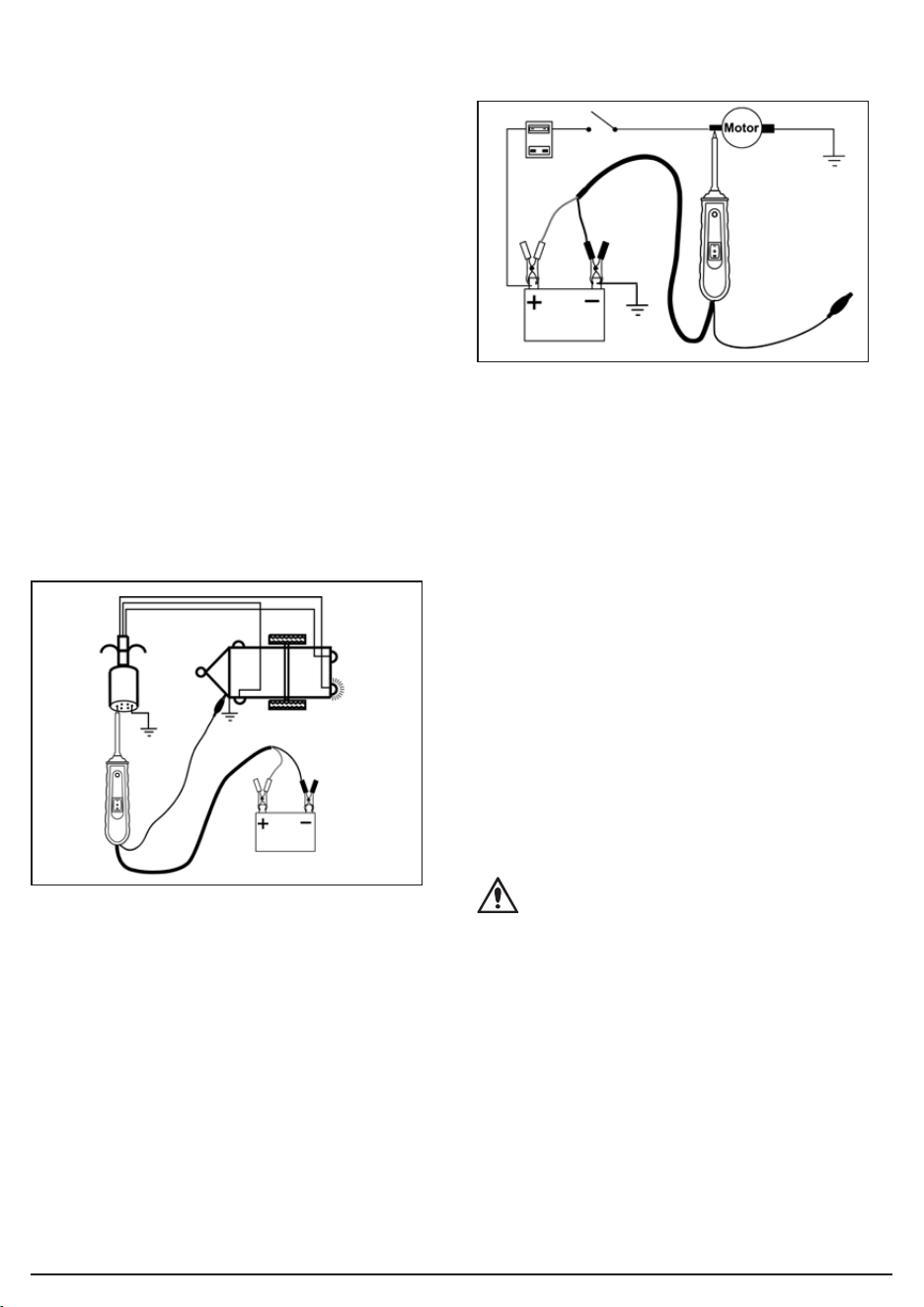
6.4 Activating Components out of the Vehicle’s
Electrical System (Fig.4)
• Use the probe tip (3) and the auxiliary ground lead (6)
together to activate and test components function
out of the vehicle’s electrical system.
Fig.1
Fig.3
Fig.2
Press LED Indicator (4)
‘I’ RED
‘II’ GREEN
Probe Tip Contact LED Indicator (4)
Positive (+) circuit RED
Negative (-) circuit GREEN
Open circuit Light o
LED turns green LED is o
Fig.4
Auxiliary
ground lead
Press the front part of the
ON/OFF switch “–” to
activate the bulb
Activate fuel pumps, starter
solenoids, magnetic clutches,
blower motors, cooling fans,
lights etc.
– 5 –
1. Connect the auxiliary ground lead’s clip (6) to the
negative terminal of the component to be tested.
2. Contact the probe (3) to the positive terminal of the
component, the LED indicator should light ‘GREEN’
indicating continuity through the component.
3. Observe the green LED indicator, then quickly press
and release the front of the power switch (II).
• If the green indicator changes immediately from
‘GREEN’ to ‘RED’, you can now proceed with further
activation.
• If the ‘GREEN’ indicator goes out, the probe unit will
sound and the probe has been overloaded.
This could happen for the following reasons:
− The contact of the tip is a direct ground or
negative voltage.
− The component is short-circuited.
− The component is a high amperage component
(i.e. starter motor).
6.5 Testing Trailer Lights and Connections (Fig.5)
To check the function and orientation of the
trailer lights
1. Connect the unit to a good battery.
2. Connect the auxiliary ground lead clip (6) to the
trailer’s ground.
3. Probe the jack contacts while pressing the ON/OFF
switch to ‘I’.
6.6 Activating Electrical Components with Positive
Voltage (Fig.6)
To activate components with positive (+) voltage
1. Contact the probe tip to the positive terminal of
the component, the LED indicator should light
up ‘GREEN’.
2. Observe the ‘GREEN’ indicator, then quickly press
and release the ON/OFF switch ‘I’.
• If the ‘GREEN’ indicator changes immediately from
‘GREEN’ to ‘RED’, you can now proceed with further
activation.
• If the ‘GREEN’ indicator goes out the probe unit will
sound and the probe has been overloaded.
This could happen for the following reasons:
− The contact of the tip is a direct ground.
− The component is short-circuited.
− The component is a high amperage component
(i.e. starter motor).
WARNING!: Applying voltage to certain circuits
incorrectly, can cause damage to a vehicle’s
electronical components. ALWAYS use the
correct schematic and diagnosing procedure
while performing testing.
Fig.5
Fig.6
– 6 –
6.7 Activating Electrical Components with Negative
Voltage (Fig.7)
Activating electrical components with negative (-)
voltage
1. Contact the probe tip to the negative terminal of the
component, the LED indicator should light up ‘RED’.
2. Observe the ‘RED’ indicator, then quickly press and
release the rear of the ON/OFF switch (II).
• If the red indicator immediately changes from ‘RED’
to ‘GREEN’, you may proceed with further activation.
• If the LED indicator goes out or if the unit sounds, the
unit has been overloaded. This could have happened
for the following reasons:
− The tip’s contact is a direct positive voltage.
− The component is short-circuited.
− The component is a high amperage component
(i.e. starter motor).
WARNING!: With this function a vehicle’s fuse
can be blown or tripped if grounding the contact
in series with it.
6.8 Jump Lead Feature (Fig.8)
• The black clip and the auxiliary ground lead are
connected directly through the Auto probe. Leave the
red clip disconnected from the vehicle’s battery to
allow the unit to be used as a long jump lead.
CAUTION!: Take care to avoid short circuits and
overloading when using the jump starter
function. In this conguration, the leads are not
protected by the Auto probe’s circuit breaker.
6.9 Checking for Bad Ground Contacts (Fig.9)
1. Probe the suspected ground wire or contact with
the probe tip.
2. Observe the ‘GREEN’ LED indicator.
3. Press the front part of the ON/OFF switch ‘I’ then
release.
• If the LED indicator changes from ‘GREEN’ to ‘RED’,
this is not a true ground.
• If the unit sounds, this circuit is most likely a direct
ground. Note: high current components such as
starter motors will also cause the unit to sound.
Fig.7 Fig.8
Fig.9
– 7 –
6.10 Following and Locating Short Circuits
• In most cases a short circuit causes a fuse to blow or
a circuit breaker to trip.
• Remove the blown fuse from the fuse box.
• Connect the probe tip to each of both contacts in
the fuse box and press the front part of the
ON/OFF switch ‘I’.
• The side which causes the LED indicator to turn o
or causes the unit to sound is the shorted circuit.
Note: this wire’s identication code or colour.
• Follow the wire as far as you can along the wiring
harness, for instance, if you are following a short in
the brake light circuit you may know that the wire
must pass though the wiring harness at the door sill.
Locate the color-coded wire in the harness and
expose it.
• Probe through the insulation of the wire with the
probe tip and press the front part of the ON/OFF
switch ‘I’ to energise the wire. If the LED indicator
turns o or the unit sounds, you have veried the
shorted wire.
• Cut the wire and energise each end with the probe
tip. The wire which causes the LED indictor to turn
o or causes the unit to sound will lead you to the
shorted area.
• Follow the wire in the shorted direction and repeat this
procedure until you nd the exact position of the short.
• When the unit sounds, the circuit breaker of the unit trips.
• After the circuit breaker trips, it will be reset
automatically after 3 to 5 seconds.
7. Disposal
• At the end of its working life, dispose of the product
responsibly and in line with local regulations.
Recycle where possible.
− DO NOT dispose of this product with domestic
waste; most local authorities provide appropriate
recycling facilities.
* Waste Electrical & Electronic Equipment.
8. Warranty
12 months from date of purchase -
Visit drapertools.com/warranty for full details.
9. Explanation of Symbols
Warning!
For use on DC circuits only.
WEEE –
Waste Electrical & Electronic Equipment
Do not dispose of Waste Electrical & Electronic Equipment
in with domestic rubbish
European conformity
UK Conformity Assessed
DC

© Published by Draper Tools Limited© Published by Draper Tools Limited
Draper Tools Europe B.V.
Oude Graaf 8
6002 NL
Weert
Netherlands
Contact Details
Draper Tools
Draper Tools Limited
Hursley Road
Chandler’s Ford
Eastleigh
Hampshire
SO53 1YF
UK
Website: drapertools.com
Email: [email protected]
Product Helpline: +44 (0) 23 8049 4344
Telephone Sales Desk: +44 (0) 23 8049 4333
General Enquiries: +44 (0) 23 8026 6355
Please contact the Draper Tools Product Helpline for repair and servicing enquiries.