AUTO PROBE WITH LCD DISPLAY 3V - 42V
MODEL NO: PP7
Thank you for purchasing a Sealey product. Manufactured to a high standard, this product will, if used according to these instructions,
and properly maintained, give you years of trouble free performance.
IMPORTANT: PLEASE READ THESE INSTRUCTIONS CAREFULLY. NOTE THE SAFE OPERATIONAL REQUIREMENTS, WARNINGS & CAUTIONS. USE
THE PRODUCT CORRECTLY AND WITH CARE FOR THE PURPOSE FOR WHICH IT IS INTENDED. FAILURE TO DO SO MAY CAUSE DAMAGE AND/OR
PERSONAL INJURY AND WILL INVALIDATE THE WARRANTY. KEEP THESE INSTRUCTIONS SAFE FOR FUTURE USE.
1. SAFETY
9 If you are in any doubt about electrical safety consult a qualified electrician.
9 Only for use with 12 - 42 volt DC systems.
8 DO NOT apply voltage or current to the probe that exceeds the specified maximum of 42V DC.
8 DO NOT use with industrial 110V systems.
8 DO NOT use on any circuit directly or indirectly connected to AC lines or any other AC power source.
8 DO NOT use with any component or circuits of the ignition system.
9 Before using this device, check the vehicle’s electrical wiring and disconnect any part or system sensitive to voltage and current pulses
such as air bags, electronic control modules, etc.
9 Always check the instructions and procedures indicated in the vehicle service manual before attempting to disconnect any part or
subsystem of the electrical circuit.
9 When not in use, store the probe carefully in a safe, dry, childproof location. Avoid extremes of temperature.
8 DO NOT use the unit around explosive gases, vapour or dust. When the power switch is operated (forwards or backwards), battery
current is conducted to the tip of the probe which may cause sparks when contacting earth or other certain circuits.
8 DO NOT use leads if damaged or if the wire is bared in any way.
8 DO NOT use this tester for any purpose other than that for which it has been designed.
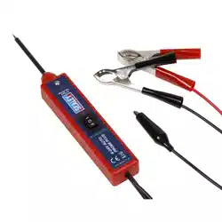
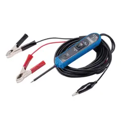
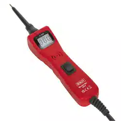
2. i INTRODUCTION
A range of functions allow automotive electricians and mechanics the ability to effectively diagnose short circuits and bad earths. The
4.6mtr lead connects to a 12V battery supply and reaches to all areas of the vehicle. Fly lead allows continuity and polarity testing with
a high-contrast LCD display with 9mm high (3V to 42V) read-out. Activate components in situ or prior to installation. Features audible
and positive/negative voltage indicator plus two integral work lights. Kit includes three probe extension leads, two wire piercing probes,
two lead adaptors and a crocodile clip. Supplied in a carry-case.
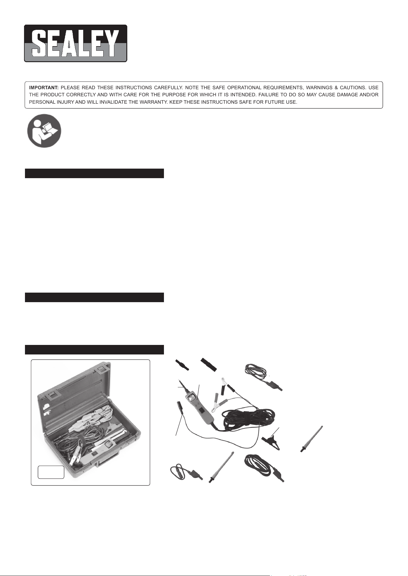
3. CONTENTS
3.1. Polarity Indicator and Audio Tone.
3.1.1. The “RED/GREEN Polarity Indicator” lights up when the probe tip voltage matches the battery voltage within ± 0.5 volts. This means
that if you contact a circuit that is not a good earth or a good positive, you will not see the “RED/GREEN Polarity Indicator” lighting.
3.1.2. The Audio Tone runs parallel to the “RED/GREEN Polarity Indicator, and will also NOT react when contacting a circuit that does not
match the battery voltage within ± 0.5 volts.
Refer to
instruction
manual
1) Probe body.
2) Probe tip.
3) Wire piercing probe (green).
4) Wire piercing probe (yellow).
5) 300mm flexi-lead.
6) 900mm flexi-lead.
7) 1800mm flexi-lead.
8) Male/male adaptor.
9) Female/female adaptor.
10) Crocodile clip (female adaptor).
1
2
3
4
5
6
7
9
10
(+)
(-)
Auxiliary earth
8
fig.
1
Original Language Version
© Jack Sealey Limited
PP7 Issue:4 (4) 17/09/18
4. OPERATION
4.1. Basic Connections.
4.1.1. Unroll the Probe cable. Connect the RED battery clip to the POSITIVE terminal of the vehicle’s battery. Connect the BLACK battery
clip to the NEGATIVE terminal.
4.1.2. Whentheprobeisrstconnectedtothebattery,itwillsoundaquickhighbeep,thenalowbeepandthengointo“PowerMode”
4.1.3. The two LED work lights will be on to illuminate the test area of the probe.
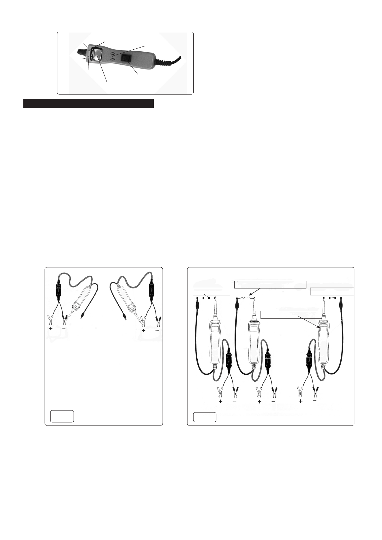
4.2. Quick Self Test.
4.2.1. Press switch toward (+) to activate the probe with a POSITIVE (+) voltage. The POSITIVE sign (+) LED should light red and the LCD
display will read the battery (supply) voltage. If the tone feature is turned on, a high pitched tone will sound.
4.2.2. Press the switch toward (-) to activate the probe with a NEGATIVE (-) voltage. The NEGATIVE sign (-) LED should light green and the
LCD display will read “0.0”. If the tone feature is turned on, a low-pitched tone will sound.
4.2.3. The probe is now ready to use.
4.3. VoltageandPolarityTesting.Seeg.2.
4.3.1. Contact the probe tip to a POSITIVE circuit. The red positive sign, (+) LED will light and the voltmeter will display the voltage.
4.3.2. A high-pitched tone will sound.
4.3.3. While the PP7 is in “Power Mode”, contact the probe tip to a NEGATIVE circuit. The green negative sign, (-) LED will light and the
voltmeter will display the voltage.
4.4. ContinuityTesting.Seeg.3.
4.4.1. Continuity can be tested on wires and components attached or disconnected from the vehicle’s electrical system and by utilizing the
Probe tip when connected with a chassis earth or the auxiliary earth lead.
4.4.2. The Probe indicates continuity using two resistance levels. When the Probe tip has a resistance to earth of less than 20K Ohms but
greater than 2K Ohms the LCD will indicate “0.0” volts but no green (-) LED.
4.4.3. When the resistance to earth is less than 2K Ohms the LCD will indicate “0.0” volts and the green (-) LED will illuminate.
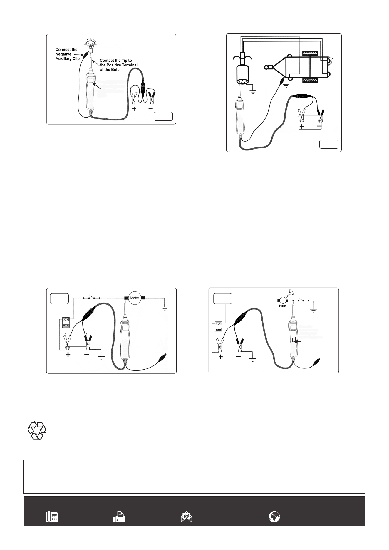
4.5. ActivatingComponentsinYourHand.Seeg.4
4.5.1. Connect the negative auxiliary clip to the negative terminal or earth side of the component being tested.
4.5.2. Contact the probe to the positive terminal of the component, the green negative sign (-) LED indicator should light GREEN indicating
continuity through the component.
4.5.3. ObservethegreenLEDindicatorandquicklydepressandreleasetheswitchforward(+).IfthegreenLEDindicatorwentoutandthe
red positive sign (+) came on, you may proceed with further activation.
4.6. TestingTrailerLightsandConnections.Seeg.5.
4.6.1. Connect the Probe to a good battery.
4.6.2. Clip the auxiliary earth clip to the trailer earth.
4.6.3. Probe the contacts at the jack and then apply voltage to them. This lets you check the function.
Original Language Version
© Jack Sealey Limited
+
-
Green LED
Speaker
(+)/off/(-) Switch
[“off” by default]
Red LED
LED
LED
(work
lights)
g.3
No continuity
Continuity<20kΏbut>2kΏ
Continuity<2kΏ
Green LED=Continuity
Contact the probe tip
to a NEGATIVE circuit.
The green negative
sign (-) LED will light,
a high pitched tone will
sound.
Contact the probe tip
to a POSITIVE circuit.
The red positive sign (+)
LED will light and the
voltage reading of the
circuit will be indicated
on the LCD display. A
high pitched tone will
sound.
g.2
PP7 Issue:4 (4) 17/09/18
4.7. ActivatingComponentsintheVehicle.Seeg.6.
4.7.1. To activate components with positive (+) voltage, contact the probe tip to
the positive terminal of the component. The green negative sign “-” LED
should light, indicating continuity to earth.
4.7.2. Whileobservingthegreen“-”LED,quicklydepressandreleasethepowerswitchforward(+).
If the green indicator has gone out and the red positive sign (+) LED has come on, you may proceed with further activation.
4.7.3. WARNING: Haphazardly applying voltage to certain circuits can cause damage to a vehicle’s electronic components. Therefore, it
is strongly advised to use the vehicle manufacturer’s schematic and diagnosing procedure while testing.
4.8. ActivatingElectricalComponentswithEarth.Seeg.7.
4.8.1. Contact the probe tip to the negative terminal of the component, the LED indicator should light RED.
4.8.2. Whileobservingthered(+)LED,quicklydepressandreleasethepowerswitchrearward(-).Iftheredindicatorwentoutandthe
green negative LED (-) came on you may proceed with further activation.
WARNING: With this function, if you are contacting a protected circuit, a vehicle’s fuse can be blown or tripped if you apply earth to it.
4.9. Jumper lead feature. See Fig.6.
4.9.1. The black clamp and the auxiliary earth lead are connected through the unit. By leaving the red clip disconnected from the vehicles battery, the
unit can be used as a long jumper lead.
4.9.2. Be careful to avoid short circuits and overloading when using this jumper function.
4.10. Checking for Bad Earth.
4.10.1. Probe the suspected earth wire or contact with the probe.
4.10.2. Observe the green negative (-) LED. Depress the power switch forward then release.
4.10.3. If the green negative sign (-) LED went out and the red positive sign (+) came on, this is not a true earth.
g.4
Press
(+)
to
illuminate
bulb.
+
-
g.5
g.6
Press
(-) to
earth
horn.
g.7
+
-
Sealey Group, Kempson Way, Suffolk Business Park, Bury St Edmunds, Suffolk. IP32 7AR
01284 757500 01284 703534 sales@sealey.co.uk www.sealey.co.uk
ENVIRONMENT PROTECTION
Recycle unwanted materials instead of disposing of them as waste. All tools, accessories and packaging should be sorted, taken to
a recycling centre and disposed of in a manner which is compatible with the environment. When the product becomes completely
unserviceableandrequiresdisposal,drainanyfluids(ifapplicable)intoapprovedcontainersanddisposeoftheproductandfluids
according to local regulations.
Note: It is our policy to continually improve products and as such we reserve the right to alter data, specifications and component parts without prior
notice.
Important: No Liability is accepted for incorrect use of this product.
Warranty:Guaranteeis12monthsfrompurchasedate,proofofwhichisrequiredforanyclaim.
Original Language Version
© Jack Sealey Limited
PP7 Issue:4 (4) 17/09/18