1
CAUTION
The ultrasonic style flow sensor described in this manual is not intended for use in safety
critical applications. Use of the device in this manner is done at the sole discretion of the
customer and/or end user of the device.
The ultrasonic style flow sensor described in this manual is not intended for use in
systems with flammable liquids or gases. Additionally, the device is not intended for
systems containing hazardous fluids or fluids other than water.
The ultrasonic style flow sensor described in this manual must be installed in
accordance with all local and federal codes or end-use standards, as applicable.
If the devices described in this manual are used in a manner not specified by the
manufacturer, the protection provided by the equipment may be impaired.
WARNING
Depressurize and vent the piping system prior to any installation or maintenance of the
flow sensor.
Features - Install - Setup - Troubleshooting
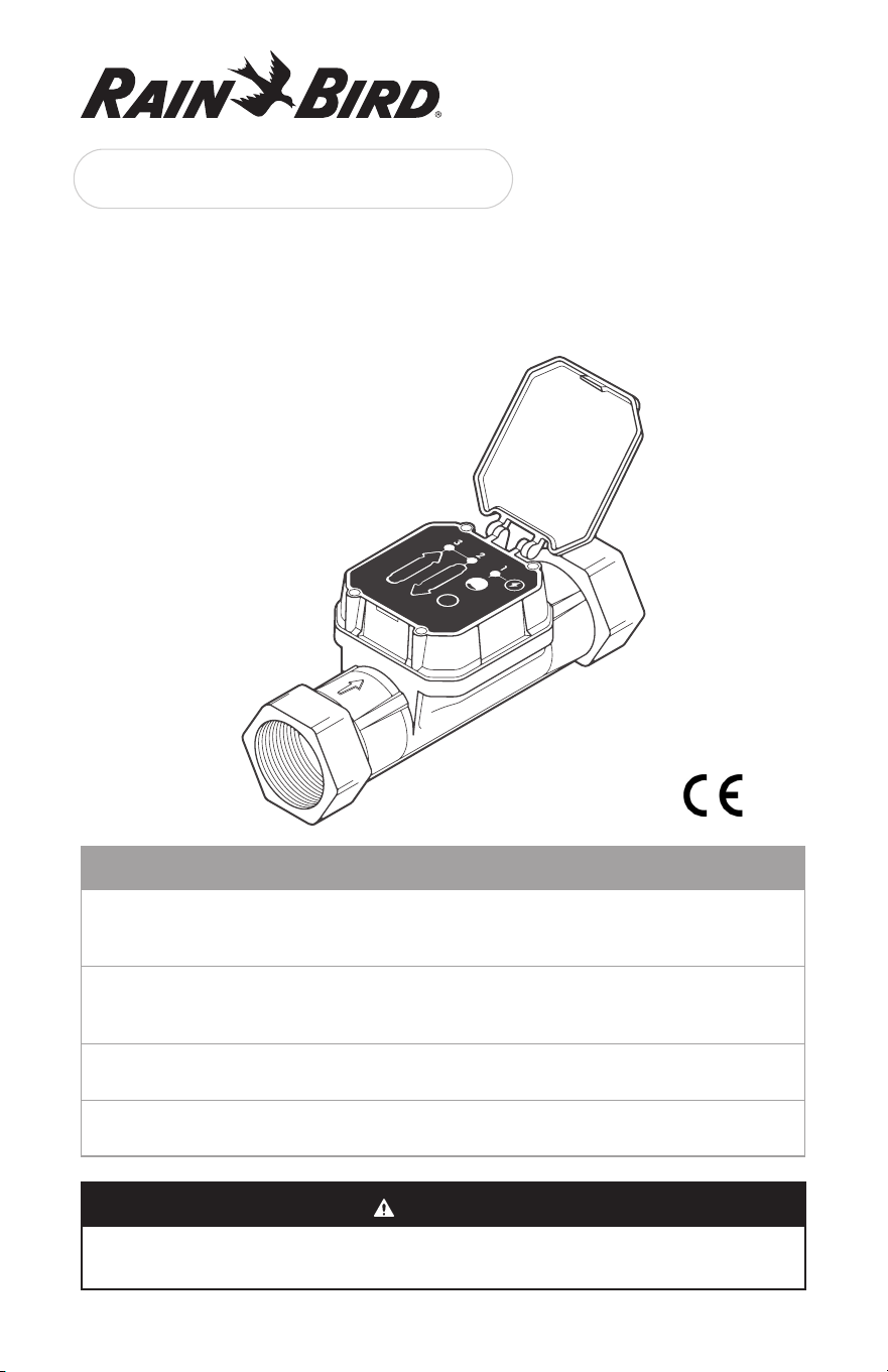
UFS Series User Guide
Ultrasonic Flow Sensor
2
1. Introduction
The Rain Bird UFS Series Ultrasonic Flow Sensors are high performance tools designed
for commercial irrigation installations where accurate low and high flow measurement are
required.
With the UFS Series, a single sensor reads both high and very low flow rates with higher
precision than traditional flow sensors at +/- 2 % of reading. They have no moving parts,
and due to glass filled nylon construction, they feature a 200 PSI rating – double that of
traditional flow sensors.
Additionally, the UFS Series does not have straight pipe requirements, simplifying
installation and allowing the UFS Series to be installed in a jumbo valve box with your
master valve!
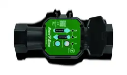
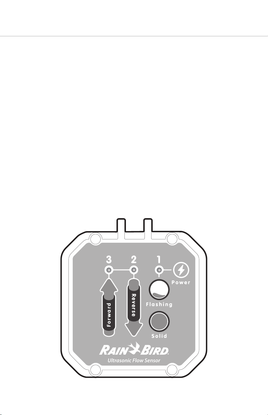
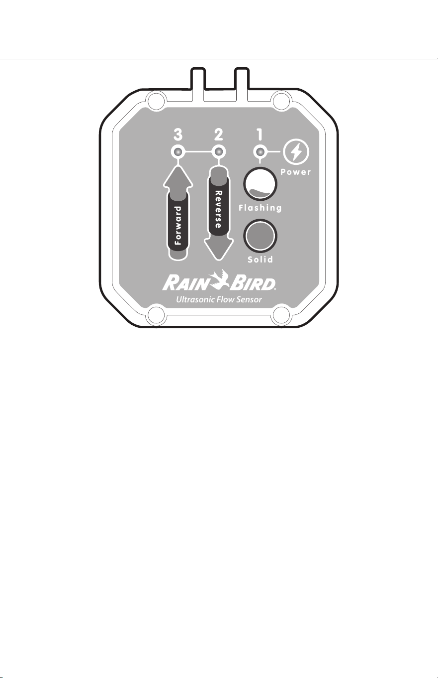
Rain Bird’s UFS Series has a diagnostic display on the top of the electronics housing with
three LEDs that identify the following flow states:
1. Flashing to Solid Green LED (right) indicates Partial Fill or Full Pipe
2. Flashing Red LED (center) – Indicates Reverse flow
3. Flashing Green LED (le) indicates Rate of Flow
U
lt
r
asonic
F
l
o
w
S
ensor
1
2
3
Flashing
Power
Solid
Forwa
r
d
Reverse
3
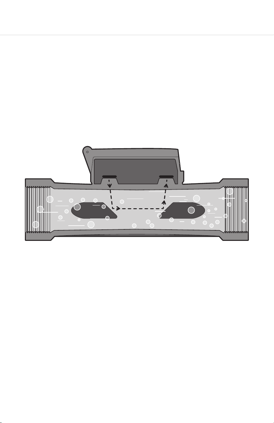
1.1 Technology
The ultrasonic flow sensor uses sound waves, transmied through the moving water in
the irrigation pipe, to measure the speed of the water flow. Two transmiers generate
and receive the soundwaves. The soundwave moving upstream will be slower than the
soundwave moving downstream. The dierence in the transit time equates to the velocity
of water flowing through the pipe.
The flow sensor generates an electrical pulse with a frequency proportional to the flow
rate. An internal preamplifier allows the pulse signal to travel up to 2000 feet (610 meters)
without further amplification. Power to operate the sensor is provided by the irrigation
controller, 2-wire sensor decoder or pulse input type flow monitor.
4
2. System Configuration
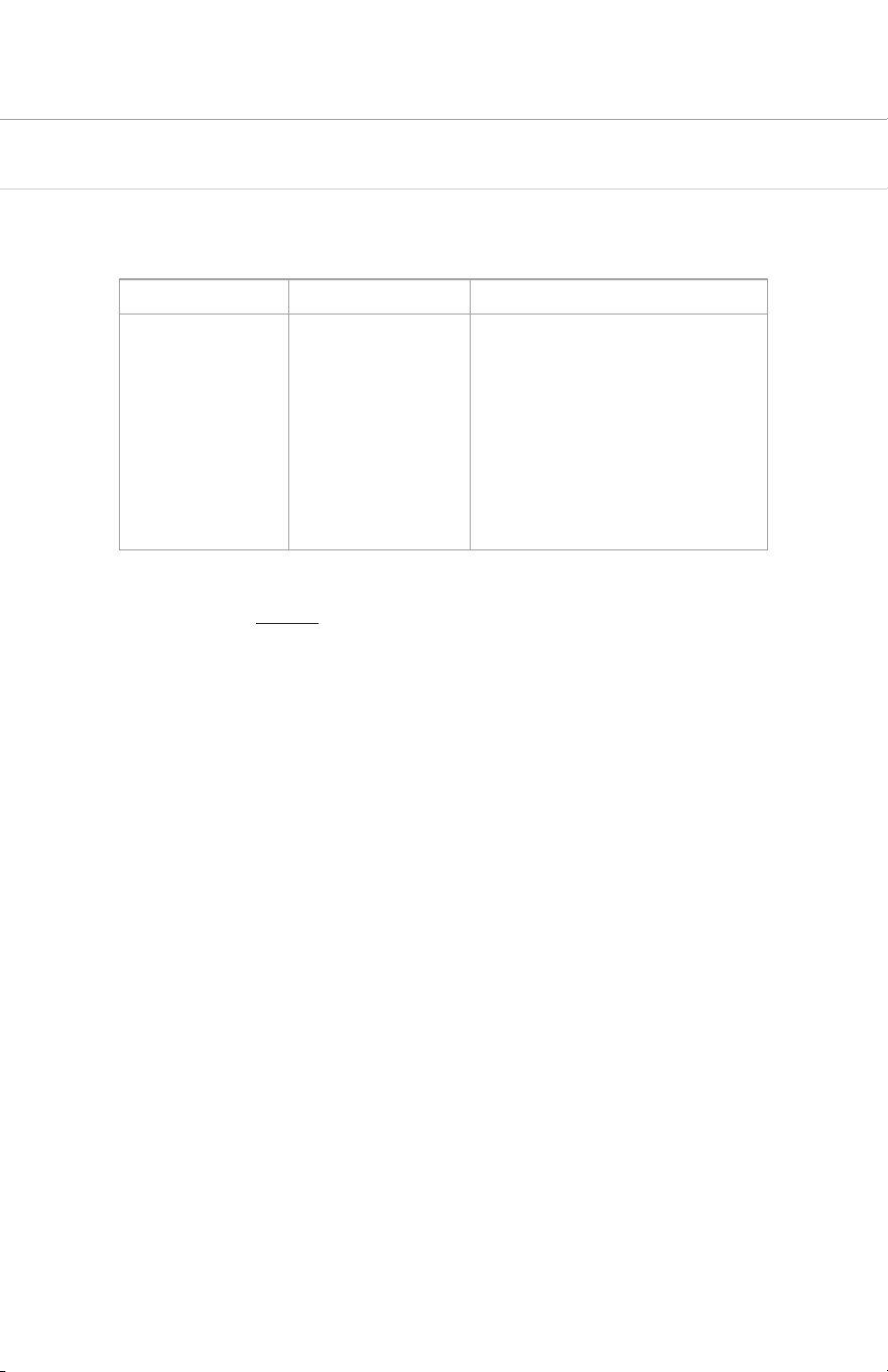
2.1 Compatibility
The UFS Series includes 2”, 1.5”, and 1” models with NPT and BSP threading. Their output is
compatible with the following Rain Bird products:
Controllers Central Control Flow Monitor/Pulse Transmiers
ESP-ME3
ESP-LXMEF
LXME2PRO
ESP-LXD
ESP-LXIVM
ESP-LXIVMP
IQ
Maxicom
SiteControl
PT322
PT5002
PT3002
They are also compatible with third-party irrigation controllers that can be configured with
a K-factor and oset (page 10).
This manual provides instructions for installation and operation of the UFS Series.
5
ESP-LXIVM
ESP-LXMEF
SD210TURF
ESP-LXD
DECPULLR
PT5002
ESP-SAT
Two-Wire Satellite
PT5002
ESP-SAT
Link Satellite and Maxicom
ESP-SITE Satellite
PT5002
LXIVMSEN
ESP-LXME2PRO
PT5002
6
3. Installation
The UFS Series utilizes long body construction, providing itself with sucient straight-pipe
requirement in most situations. Ultrasonic Flow Sensor readings are less aected by flow
irregularities caused by valves, fiings, pipe bends, or other obstructions than traditional
flow sensors. This means it can connect directly to a Rain Bird master valve or other device.
NOTE
The UFS Series unit size (diameter) should be equal-to or smaller than the incoming
piping. Using a UFS Series which is larger than the incoming pipe may lead to air being
trapped in the unit.
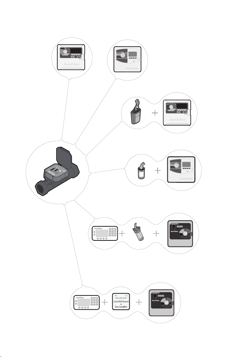
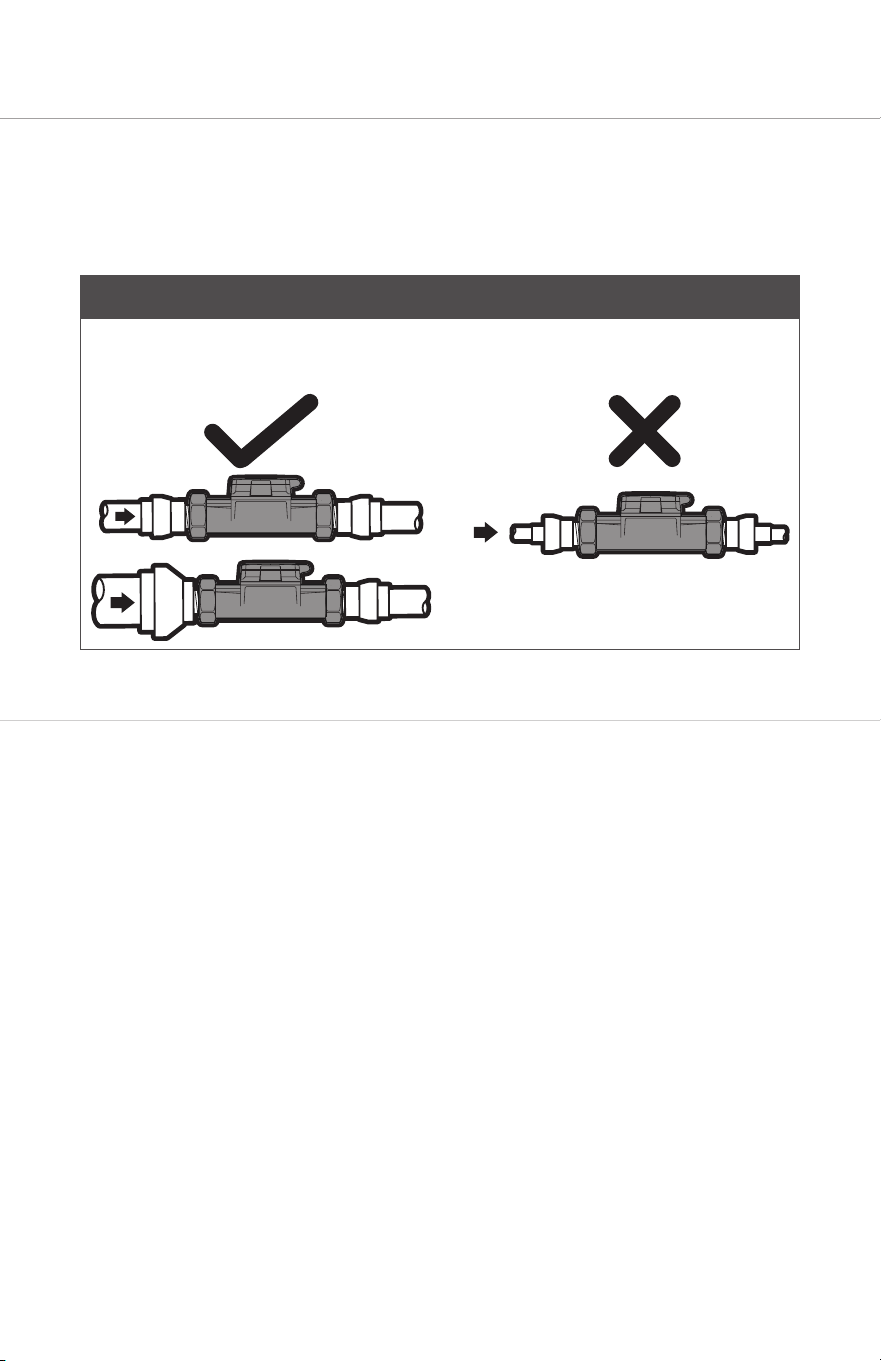
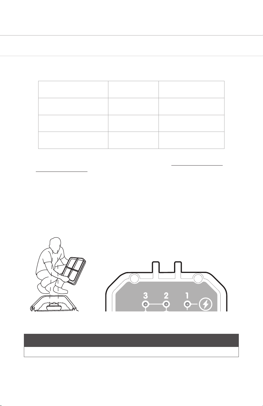
3.1 Mechanical Installation Procedure
Entrapped air in the pipe will cause inaccurate or “no-flow” readings. For best performance
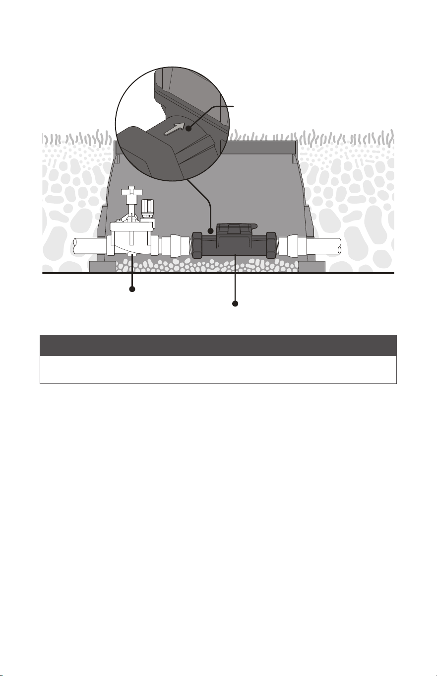
install the meter horizontally below or above ground, as shown in figure 3.1.1.
1. Use union fiings on both sides of the UFS Series for ease of install and maintenance.
2. Make sure the UFS Series arrow faces the direction of flow.
3. Apply Teflon tape on all threaded connections. DO NOT OVER TIGHTEN.
7
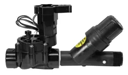
3.1.1 Typical Horizontal Installation (Recommended)
Master Valve
UFS Series Flow Sensor
Direction of flow
NOTE
The UFS Series can be installed in a vertical application with the direction of flow arrow
pointing upwards.
8
3.2 Electrical Installation Procedure
CAUTION
Disconnect the power from the flow sensor source and/or receiving device prior to
any installation or maintenance of the system. Connecting power (24VAC, 110VAc, etc.)
directly to the flow sensor wires will damage the sensor.
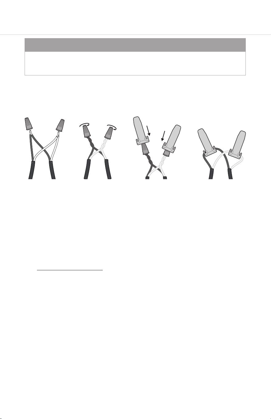
1. Use WC-20 Wire Splice connectors to connect the wire leads from the Rain Bird UFS
Series to a 2-conductor shielded 20 AWG (or larger) flow sensor cable (Paige Electric
P7162D or P7315D shielded cable or similar).
2. Route the cable from the Rain Bird UFS Series to the irrigation controller, 2-wire sensor
decoder or pulse input type flow monitor. The cable may be extended up to 2000
feet. Be sure to leave enough flexibility in the cable or conduit to allow for future
service of the sensor, if necessary.
3. When connecting to an irrigation controller, 2-wire sensor decoder or pulse input type
flow monitor, connect the red wire to FLOW (+) terminal or wire, connect the black
wire to FLOW (–) terminal or wire.
4. When interfacing with other equipment, consult the manufacturer for input
designations. The signal wave forms and power requirements are as shown in
“Specifications” on page 17 of this manual.
5. Aer all electrical connections have been made, turn on power at the irrigation
controller, 2-wire sensor decoder or pulse input type flow monitor. It may take 15
seconds before the green power LED-1 illuminates.

9
3.3 Installation Test Procedure
There are three LED lights visible on the top of the Rain Bird UFS Series Ultrasonic Flow
Sensor. Once connected to a powered system:
1. Run manual irrigation program from the controller
2. Once irrigation starts to run check that LED 1 is solid green
3. Check that UFS Series LED 3 (green) is flashing
4. Verify that the controller is registering flow rate. See your controller manual for detail
on how to read flow from your controller.
NOTE
Once flow starts, readings from the controller will not be instantaneous. The lines need
time to purge air, and the controller needs time to read the pulses from the UFS in order
to register accurate readings.
10
4. Controller Programming
• Your UFS Series unit will need to be established in the irrigation controller’s
programming.
• This should be found in the “Flow Sensors” area of the programming. This will vary by
controller, please refer to your controller manual for more specific guidance.
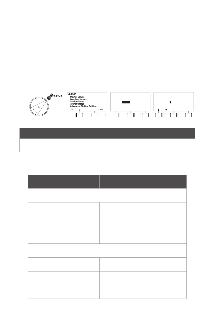
Controller Setup Example
SETUP
Next
Master Valves
Weather Sensors
Station Setup
Flow Sensors
Advanced Station Settings
Next
Type:
FS 01
Flow Sensor Setup
Custom
Next
K Factor:
Offset:
FS 01
Flow Sensor Setup
001.000
+00.000
NOTE
Shown above is a common example, your controller’s interface may dier, please consult
the manual of your specific controller.
See below for the K-Factor and Oset values per the respective UFS Series model:
Model Size K Oset Flow Range
NPT Models
UFS100 1 Inch 0.714 0.000 0.3 – 50 GPM
UFS150 1 ½ Inch 1.70 -0.316 0.5 – 110 GPM
UFS200 2 Inch 2.849 0.1439 1.0 – 200 GPM
BSP Models
UFS100BSP 1 Inch 0.714 0.000 0.3 – 50 GPM
UFS150BSP 1 ½ Inch 1.70 -0.316 0.5 – 110 GPM
UFS200BSP 2 Inch 2.849 0.1439 1.0 – 200 GPM
11
5. UFS Series Indicator lights
U
lt
r
asonic
F
l
o
w
S
ensor
1
2
3
Flashing
Power
Solid
Forwa
r
d
Reverse
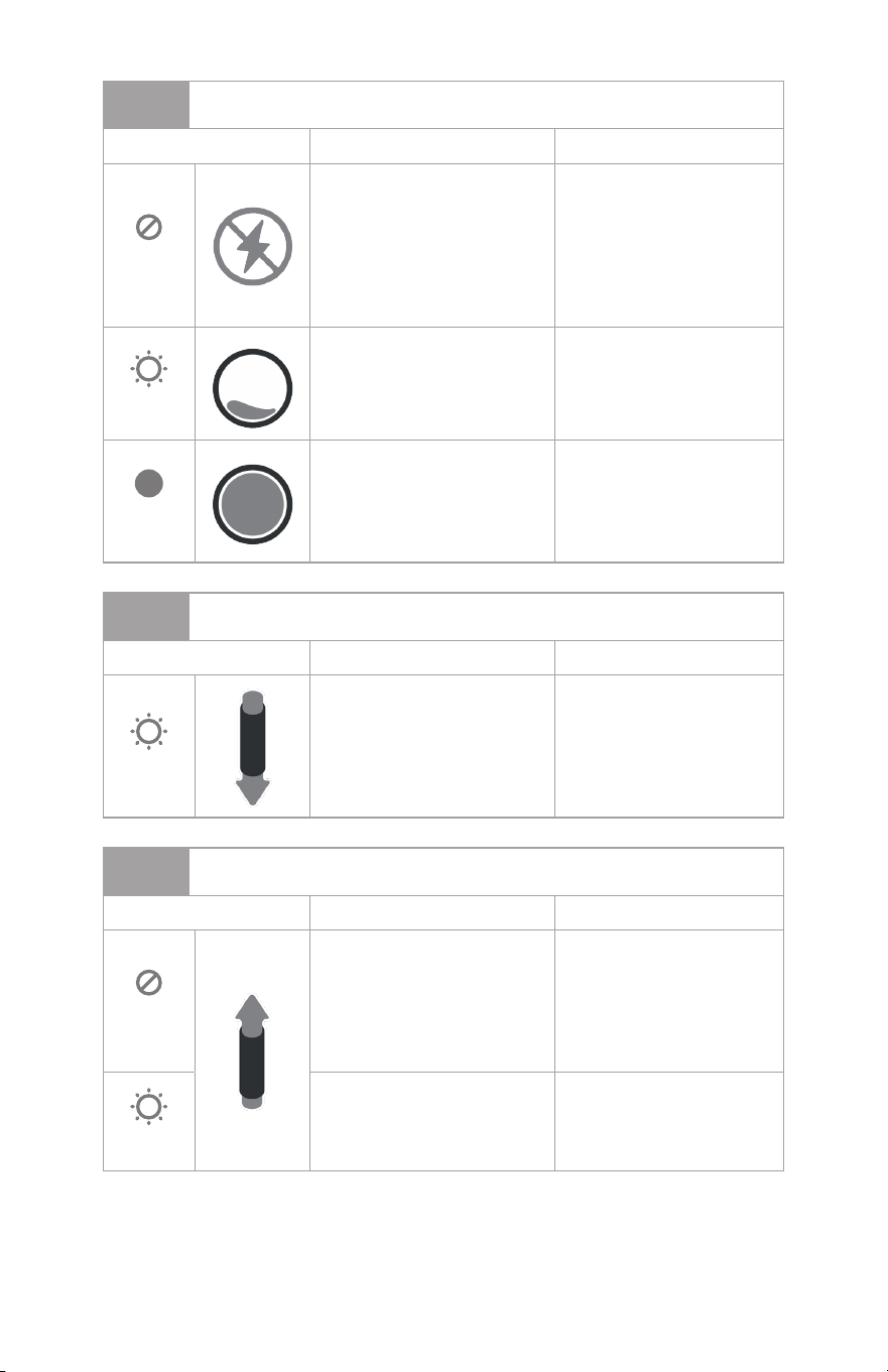
Under standard operation, water flowing forwards through the system; indicator light 1
should be solid on, indicator light 2 should be o and light 3 should be flashing. Other
indicator states are described on the following page.
12
1
Green LED
State Condition Correction
O
There is no power to the
flow sensor or insucient
power for normal operation,
or the Red and Black wires
have been reversed at
the flow sensor or on the
controller.
Check the power and
wiring.
Flashing
Power is connected and
is sucient for operation.
Insucient water in the pipe
for proper operation.
Check to ensure the pipe
is full of water.
Solid
Power is connected and
is sucient for operation.
Pipe is full and there is
sucient water in the pipe
for proper operation.
None (normal operation).
2
Red LED
State Condition Correction
Flashing
Water is flowing in the
reverse direction. LED will
flash proportionally to the
flow rate.
Check arrow on meter is
in the same direction as
expected flow. Check for
reverse flow conditions.
3
Red LED
State Condition Correction
O
No forward water flow Check controller
program times or manual
run condition. Check
for closed valves or
obstructions preventing
water flow.
Flashing
Water is flowing in the
forward direction. LED will
flash proportionally to the
flow rate.
None (normal operation).
13
6. Trouble Shooting
6.1 Initial Trouble Shooting
1. Confirm that the expected flow rates are above the minimum recommended flow rates
for the UFS Series (see table below). This will usually purge any air out of the line.
Model Size Minimum Flow Rate
UFS100 / UFS100BSP 1 Inch 0.3 GPM
UFS150/ UFS150BSP 1 ½ Inch 0.5 GPM
UFS200/ UFS200BSP 2 Inch 1.0 GPM
2. Ensure that the UFS Series has been wired correctly, (see “Electrical Installation
Procedure” on page 8)
3. Ensure there is flow in the system by running a manual irrigation program from the
controller. Check to see if water is being emied as expected.
4. Check the LED lights on the flow sensor upper body and ensure they indicate
expected operating condition, as opposed to showing a non-full pipe or reverse flow.
These light conditions would indicate problems like air in your line which would need
to be solved before the remainder of trouble shooting.
Flashing O On
U
lt
r
asonic
F
l
o
w
S
ensor
1
2
3
Flashing
Power
Solid
Forwa
r
d
Reverse
NOTE
LED 3 will only be flashing if water is flowing through the system (see step 2).
14
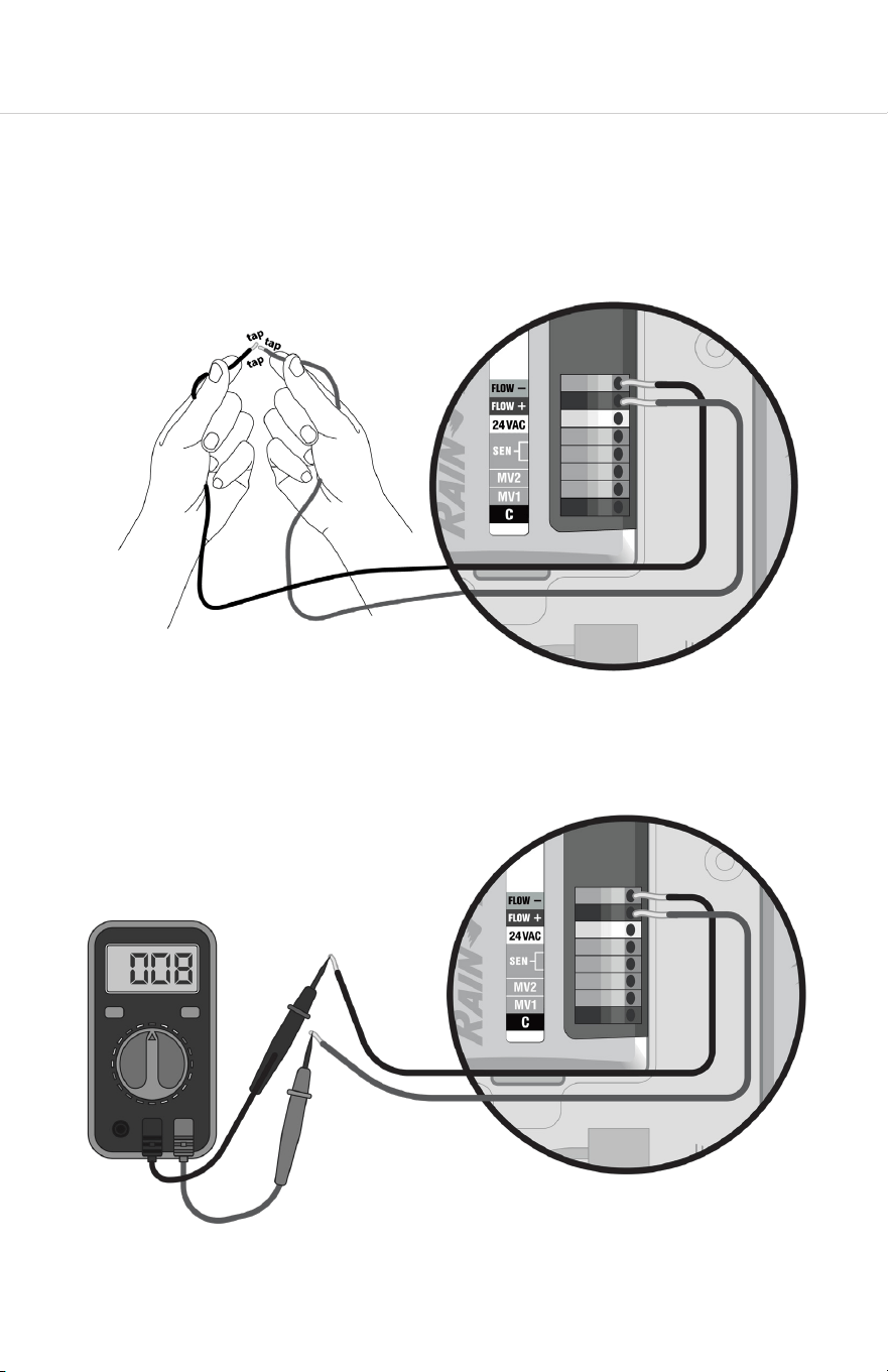
6.2 Traditionally Wired Controllers
1. If the controller is not recognizing a flow input from this sensor, or if the lights are not
on, test the controller itself by disconnecting the flow sensor, and very quickly and
repeatedly short together the flow +/- terminals or wires that connected the flow
sensor to the controller. Do this about once a second for 30 seconds. The controller
should recognize this shorting as flow. If it does not, the problem is in the controller,
and not the flow sensor or the wiring to it.
2. If the controller appears to be working, while the sensor is still disconnected measure
the open circuit voltage on the controller’s sensor input terminals. This voltage must
be between 8…24V DC for the sensor to operate.
15
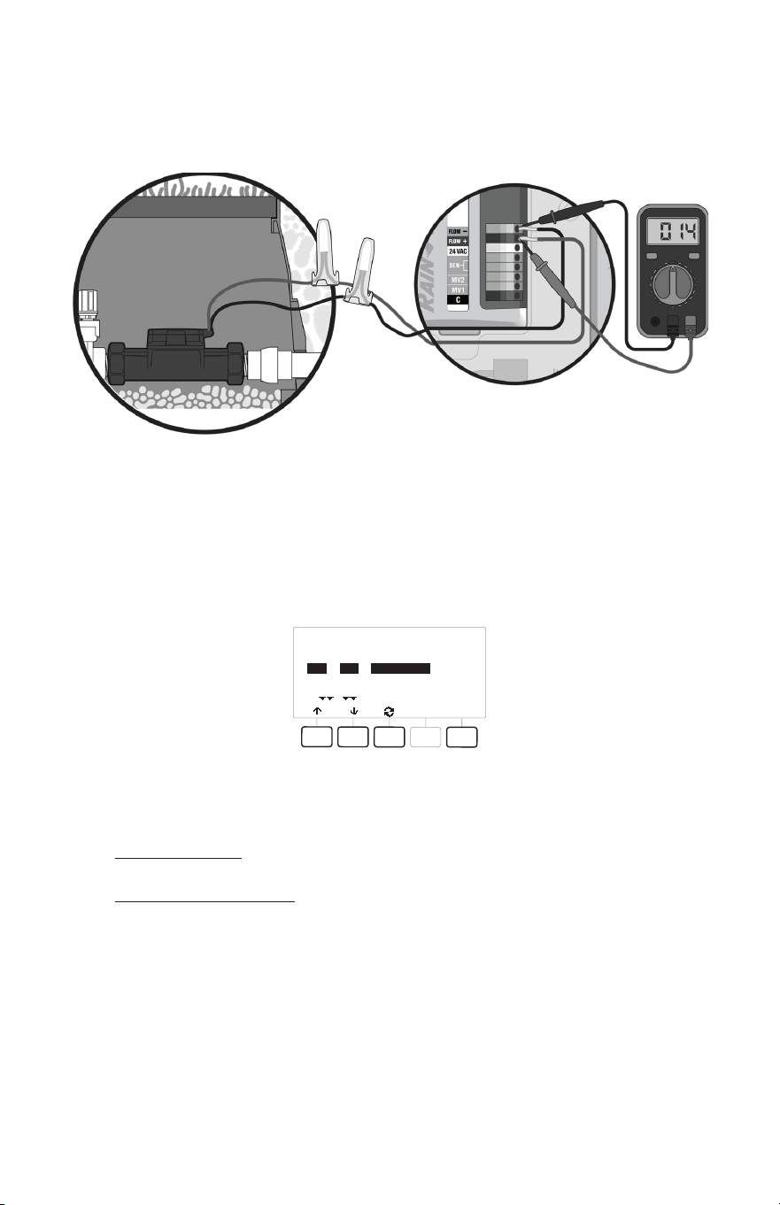
3. If the voltage is acceptable, reconnect the flow sensor to the controller and re-
measure the voltage at the sensor input terminals. The voltage should drop slightly.
If no drop is observed, the sensor is wired backwards, or there is a break in a wire or
splice, or the sensor is open internally.
4. If the voltage drops to near zero, there is either a short in the wiring or splice, or the
sensor is shorted internally.
5. If the voltage drops below 8V—but not low enough to levels indicating a short—there
is most likely moisture penetration or corrosion in the wiring or in the sensor itself. See
the manual for your specific controller for wiring trouble shooting and diagnostics.
RASTER RESULTS
Done
Type
STA
STA
STA
#
001
002
003
Status
Open Circuit
Open Circuit
Open Circuit
6. If you are still experiencing issues with your UFS Series then contact Rain Bird Pro
Support:
+1 (800) 396-5166
prosupport@rainbird.com

16
6.3 2-Wire Controllers (address based controllers)
Check the LED lights on the flow sensor upper body. The troubleshooting process will
dier depending on whether LED is illuminated or not. Please refer to the appropriate
section below to trouble shoot 2-wired controllers.
6.3.1 If Power is Reaching the UFS (LED 1 is illuminated)
1. If the lights are illuminating as expected, then the controller is successfully powering
the UFS. If your controller is not registering expected flow readings, disconnect the
UFS from the decoder.
2. Short (touch together) the wires from the decoder that connected to the UFS. Touch
them together about once a second for a duration of about 30 seconds. The
controller should register this as flow while you are performing this task.
3. If not recognized as flow, then double check the set-up of the UFS in the controller
programming. The UFS must be established correctly and your controller’s Flow
Watch or equivalent must be on.
4. If the shorting is recognized as flow, then re-check your installation of the UFS. The
polarity of the wiring must be correct (red to red, black to black), and the direction of
the flow must be correct (see arrows on the UFS).
6.3.2 If No Power is Reaching the UFS (LED 1 is not illuminated)
1. If the UFS is not showing lights illuminated on the on board display, then it is not
receiving sucient power to operate. Disconnect the terminals (wires) from the
decoder to the UFS. Measure the voltage of the decoder terminals. This voltage
should be around 10 volts DC.
2. If the voltage is 10 volts DC but the UFS lights are not illuminating, then there may
be a problem with the UFS unit. Double check that you have good splices and that
the wires are connected at correct polarity. If this does not solve the problem, then
contact Rain Bird for further assistance.
3. If the voltage is below 8 volts DC, then the UFS is not receiving sucient power to
operate. The problem may be your decoder, wire path, distance from the controller,
or the controller itself. Consult the user manuals for these other components of your
irrigation system for additional troubleshooting on these potential sources of the
problem.
17
7. Specifications
Materials • Body; GFN (Glass Filled Nylon)
• Upper: PPO (Poly Phenyl Oxide)
Sizes • 1” Female Threaded (NPT & BSP)
• 1 ½” Female Threaded (NPT & BSP)
• 2” Female Threaded (NPT & BSP)
LED Indicators • Power (On/O and Full Pipe Indication)
• Flow (Flashing proportional to flow rate)
• Reverse Flow
Pressure Rating 200 PSI Working Pressure
Temperature 32° - 150° F Working Temperature
Accuracy ± 2 % of Reading over recommended design flow range
Repeatability ± 2 % of Reading over recommended design flow range
Power Supply voltage = 8V DC min. 35V DC max.
Quiescent current = 600 µA (typical)
OFF State (V
High
) = Supply voltage – (600 µA * Supply
impedance)
ON State (V
Low
) = 1.2V DC @ 40 mA (15 Ω + 0.7V DC)
Output Frequency 0.5…200 Hz
Output Pulse Width 5 msec ±25%
Environmental • IP 68 / NEMA 4X
• Suitable for pollution degree 4 environments
• Suitable for outdoor use below grade
• Suitable for use in submerged installations (< 3 . water)
Electrical Cable 4 feet of 2-conductor AWG 18 UL PTLC drain wire provided
for connection to irrigation controller. Rated to 221° F. May
be extended to a maximum of 2000 feet with 20 AWG (or
larger) shielded flow sensing cable (Paige Electric P7162D or
equal) suitable for direct burial, or appropriate for installation.

18
Page Intentionally Le Blank

19
Page Intentionally Le Blank

20
SUPPLIER’S DECLARATION OF CONFORMITY
Responsible Party – U.S. Contact Information
Rain Bird Corporation
9491 Ridgehaven Court, Suite C,
San Diego, CA 92123, USA
www.rainbird.com
Unique Identifier: UFS100, UFS150, UFS200
FCC Compliance Statement
Note This equipment has been tested and found to comply with the limits for a Class B
digital device, pursuant to part 15 of the FCC Rules. These limits are designed to provide
reasonable protection against harmful interference in a residential installation. This
equipment generates, uses and can radiate radio frequency energy and, if not installed
and used in accordance with the instructions, may cause harmful interference to radio
communications. However, there is no guarantee that interference will not occur in a
particular installation. If this equipment does cause harmful interference to radio or
television reception, which can be determined by turning the equipment o and on, the
user is encouraged to try to correct the interference by one or more of the following
measures:
• Reorient or relocate the receiving antenna.
• Increase the separation between the equipment and receiver.
• Connect the equipment into an outlet on a circuit dierent from that to which the
receiver is connected.
• Consult the dealer or an experienced radio/TV technician for help.
NOTICE:
Changes or modifications not expressly approved by Rain Bird Corporation could void the
user’s authority to operate the equipment.
®
Registered Trademark of Rain Bird Corporation
© 2024 Rain Bird Corporation D42475