Read all safety warnings and instructions. Failure to follow the warnings
and instructions may result in electric shock, fire and/or serious injury.
Save all warnings and instructions for future reference.
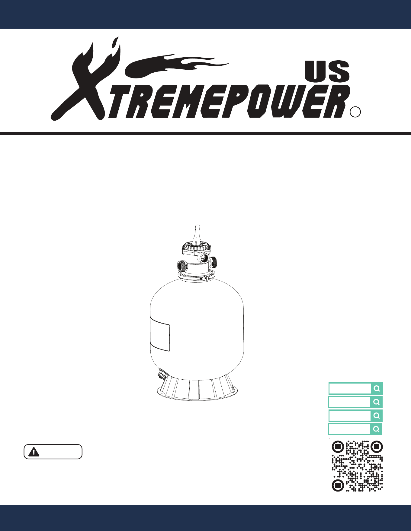
INSTALLATION AND USER’S GUIDE
75139
7-WAY
16”
ABOVE & IN-GROUND POOL SAND FILTER
DANGER
75142
75140
7-WAY
19”
75141
7-WAY
24”
75142
7-WAY
22”
75141
75140
75139


TABLE OF CONTENTS
1
TABLE OF CONTENTS
IMPORTANT SAFETY INSTRUCTIONS
GENERAL SAFETY
OVERVIEW (PRODUCT INFORMATION)
VALVE FUNCTIONS
PRODUCT DIMENSIONS
SPECIFICATIONS
INSTALLATION
FILTER TANK ASSEMBLY
OPERATION
PRIMING THE PUMP
VALVE FUNCTIONS
TROUBLESHOOTING
REPLACEMENT PARTS 33
Customer Service and Technical Support
Legends and Symbols
Parts Diagram 33
DISCLAIMER 34
1
34
2
2
3
4
4
5
5
6
6
10
18
18
21
29
PACKAGING CONTENTS 4
INSTALLATION LAYOUT DIAGRAM
IMPORTANT SAFETY INSTRUCTIONS
2
For safety reasons, children should not be allowed to use this product.
Failure to comply with all instructions and warnings may lead to severe bodily injury or
even death. It is strongly recommended that only a qualified pool service professional install and service
this product. Prior to using this product, installers, operators, and owners must carefully review these
warnings and all instructions provided in the owner's manual. It is essential to leave these warnings and
the owner's manual with the pool owner for their reference and safety.
ATTENTION INSTALLER: This manual contains vital information regarding the installation, operation,
and safe use of this product. It is essential to provide this manual to the end user of the product. Failure
to read and follow all instructions could lead to severe injuries.
USE OF NON-XTREMEPOWERUS REPLACEMENT PARTS VOIDS WARRANTY
DANGER: Ignoring these hazards can result in death, severe personal injury, or
significant property damage.
WARNING: Indicates potential hazards that can result in severe personal injury,
death, or significant property damage. Ignoring these warnings presents a real
danger.
CAUTION: Indicates potential hazards that can result in minor or moderate personal
injury, property damage, or actions that are unpredictable and unsafe. Ignoring these
cautions presents a potential hazard.
NOTICE: This label indicates important special instructions that are not directly
related to hazards.
This guide provides instructions for installing and using the product. If you have any questions about the
product, please contact XtremepowerUS.
This guide contains important information about safely installing and operating this product. After
installation, make sure to share this information with the owner/operator or leave it with them for their
reference.
Legends and Symbols
When you come across the safety-alert symbol on the product or in this manual, pay attention to the
following signal words and remain vigilant about the potential for personal injury.
IMPORTANT SAFETY INSTRUCTIONS
DANGER
WARNING
WARNING
CAUTION
NOTE
DANGER
IMPORTANT SAFETY INSTRUCTIONS
3
• Code Compliance: Adhere to all state and local codes regarding pool construction, installation, and
operation. Failure to comply may result in unsafe conditions.
• Chemical Hazard: Do not store chemicals near the pool. Chemical spills and fumes can weaken the
pool structure, leading to potential failures.
• Children’s Safety: Do not allow children to operate or use the sand filter. Position equipment to
prevent it from being used as access to the pool by young children.
• Entrapment Risk: Ensure all plugs used for pressure testing or winterization are removed from
suction outlets to prevent suction entrapment.
• Severe Injury or Death Risk: Improper installation or use of this sand filter can result in serious injury
or death. Installers, pool operators, and pool owners must read all instructions and safety warnings
before using this sand filter.
• Hazardous Pressure: Pool and spa circulation systems operate under high pressure. Failure to
follow safety instructions could cause the pump housing or filter to violently separate, leading to
severe injury, death, or property damage. Before servicing, ensure the system is off, and the
manual air relief valve is open.
• Separation Hazard: Improper assembly or maintenance can lead to violent separation of
components, causing severe injury or death. Always ensure all system components are correctly
assembled and secure.
DANGER
WARNING
GENERAL SAFETY
NOTE
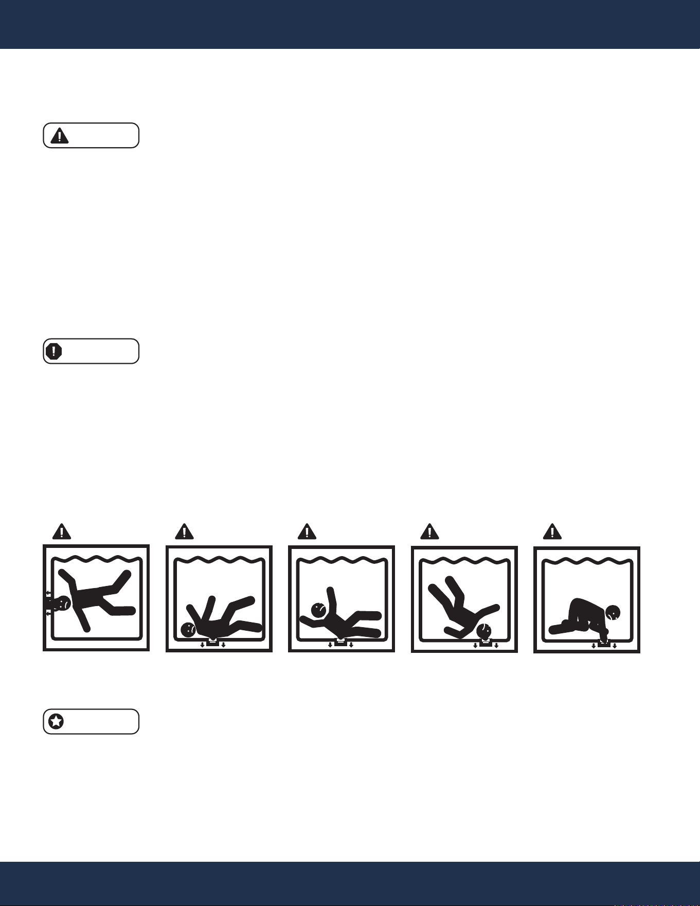
SUCTION ENTRAPMENT HAZARD
DANGER DANGER
DANGER DANGER DANGER
• Proper Maintenance: Regularly inspect and replace worn or damaged components, such as
clamps, gauges, and o-rings, to maintain safe operation.
• Grounding Requirement: Ensure the filter tank is properly grounded before connecting to other
equipments to prevent hazards.
4
OVERVIEW (PRODUCT INFORMATION)
OVERVIEW (PRODUCT INFORMATION)
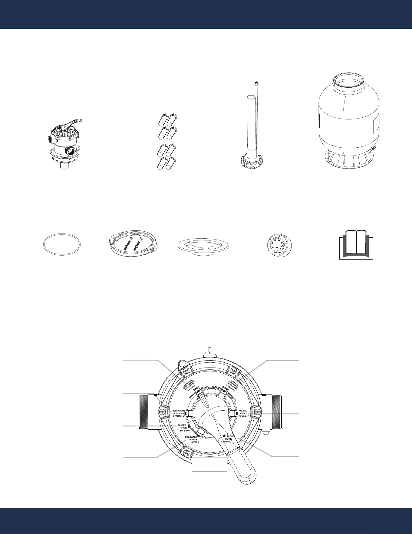
PACKAGING CONTENTS
PARTS # 1
FILTER TANK WITH
DRAIN PLUG & BASE
1 PC(S)
PARTS #
5 & 6
MEDIA ASSEMBLY
W/ AIR RELEASE
1 SET(S)
PARTS # 3
MEDIA LATERAL
8 PC(S)
PARTS
USER’S GUIDE
1 PC(S)
PARTS # 9
7-WAY VALVE
1 PC(S)
psi
bar
KL1.6
1
0
10
20
30
40
50
60
2
3
4
PARTS # 12
PRESSURE GAUGE
1 PC(S)
PARTS # 7
LARGE O-RING
1 PC(S)
PARTS # 8
FLANGE CLAMP
1 SET(S)
PARTS #
10
FUNNEL
1 PC(S)
VALVE FUNCTIONS
RECIRCULATE
RINSE
WINTER
BACKWASH
FILTER
WASTE
CLOSED
5
OVERVIEW (PRODUCT INFORMATION)
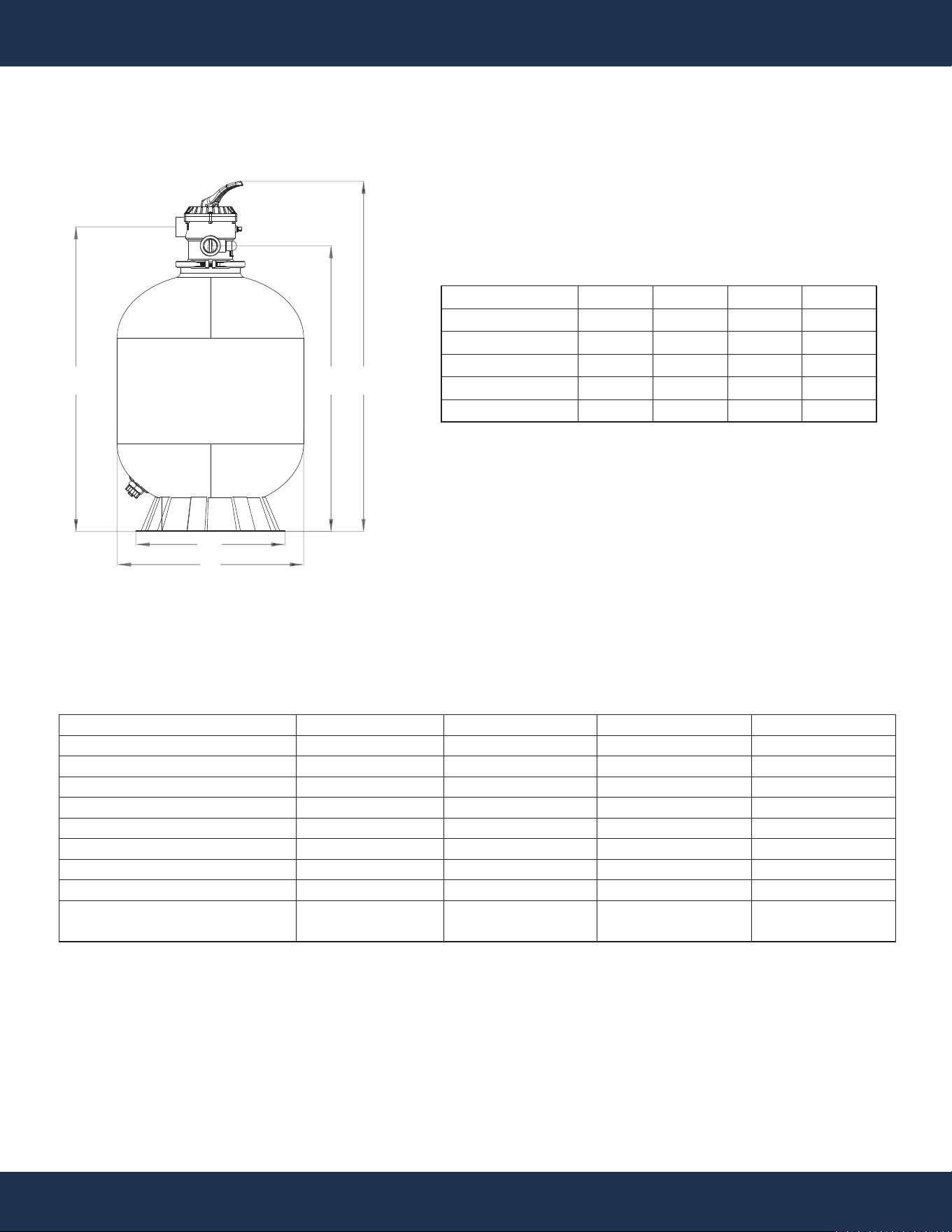
SPECIFICATIONS
PRODUCT DIMENSIONS
A B
E
C
D
75140
31.7”
29.3”
36.6”
18.9”
19”
75139
27”
24.6”
31.9”
15.8”
16”
DIMENSION #
A
B
C
D
E
75141
38.8”
36.4”
43.7”
18.9”
24”
75142
33.2”
30.8”
39”
18.9”
22”
SKU #
FILTER TANK SIZE
SAND CAPACITY
MAX FILTER (10 HR / DAY)
MAX WATER TEMP.
MAX PRESSURE
FILTER AREA (SQ FT)
CONTROL VALVE TYPE
VALVE INLET / OUTLET
SUITABLE POOL TYPE
75139
16”
UP TO 100 LBS
21,000 GAL
105°F
50 PSI (3.5 BAR)
1.35
7-WAY
1.5” NPSM
IN / ABOVE
GROUND
75140
19”
UP TO 175 LBS
25,200 GAL
105°F
50 PSI (3.5 BAR)
2.1
7-WAY
1.5” NPSM
IN / ABOVE
GROUND
75141
24”
UP TO 300 LBS
37,200 GAL
105°F
50 PSI (3.5 BAR)
3.14
7-WAY
1.5” NPSM
IN / ABOVE
GROUND
75142
22”
UP TO 250 LBS
31,200 GAL
105°F
50 PSI (3.5 BAR)
2.64
7-WAY
1.5” NPSM
IN / ABOVE
GROUND
INSTALLATION
6
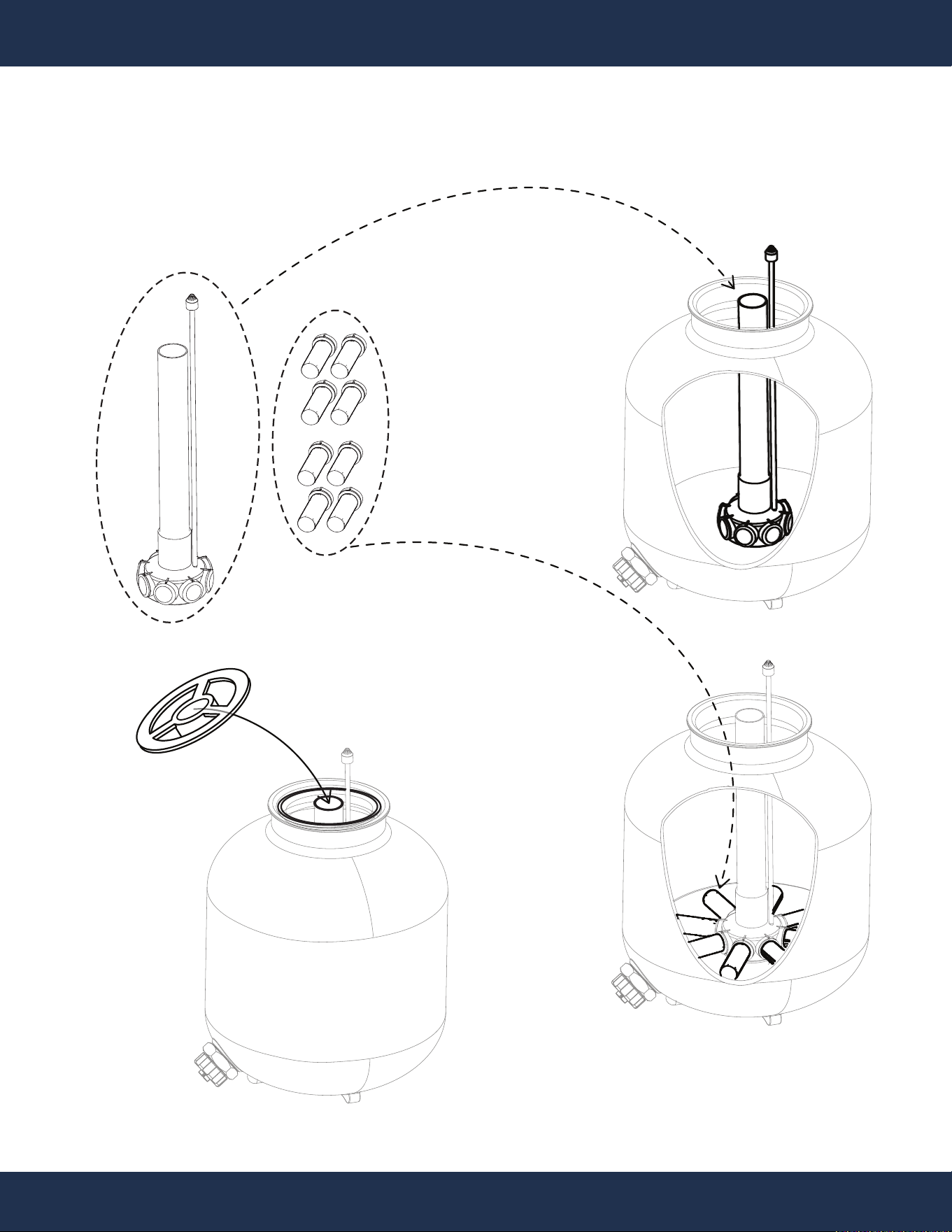
INSTALLATION
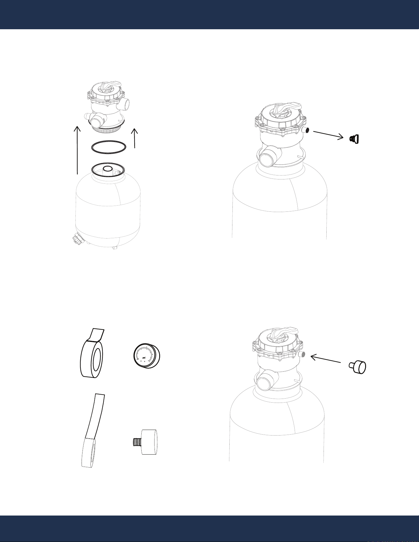
FILTER TANK ASSEMBLY
PARTS # 5 & 6
PARTS # 1
PARTS # 10
PARTS # 3
STEP 1
INSTALLATION
7
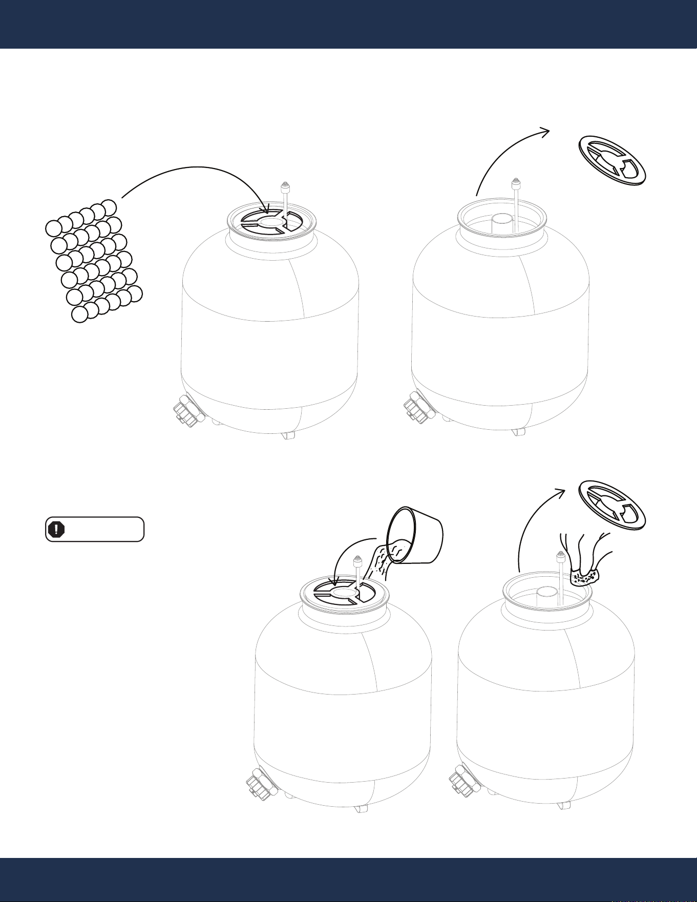
(filter sand not included)
Use only POOL FILTER SAND for this step.
WARNING
Sand Selection and Loading Requirements:
Commonly used sand: #20 (0.71MM quartz sand)
Sand density: 0.1 LB / FT³ (1.6 KG / M³)
Standard weight for sand loading: 50 LBS
Maximum sand loading in the tank: Fill up to
two-thirds of the filer tank.
Pool Filter Media Sand
Pool Filter Media Balls
PARTS # 10
STEP 2
(filter balls not included)
REMOVE IT BEFORE
INSTALL VALVE
INSTALLATION
8
psi
bar
KL1.6
1
0
10
20
30
40
50
60
2
3
4
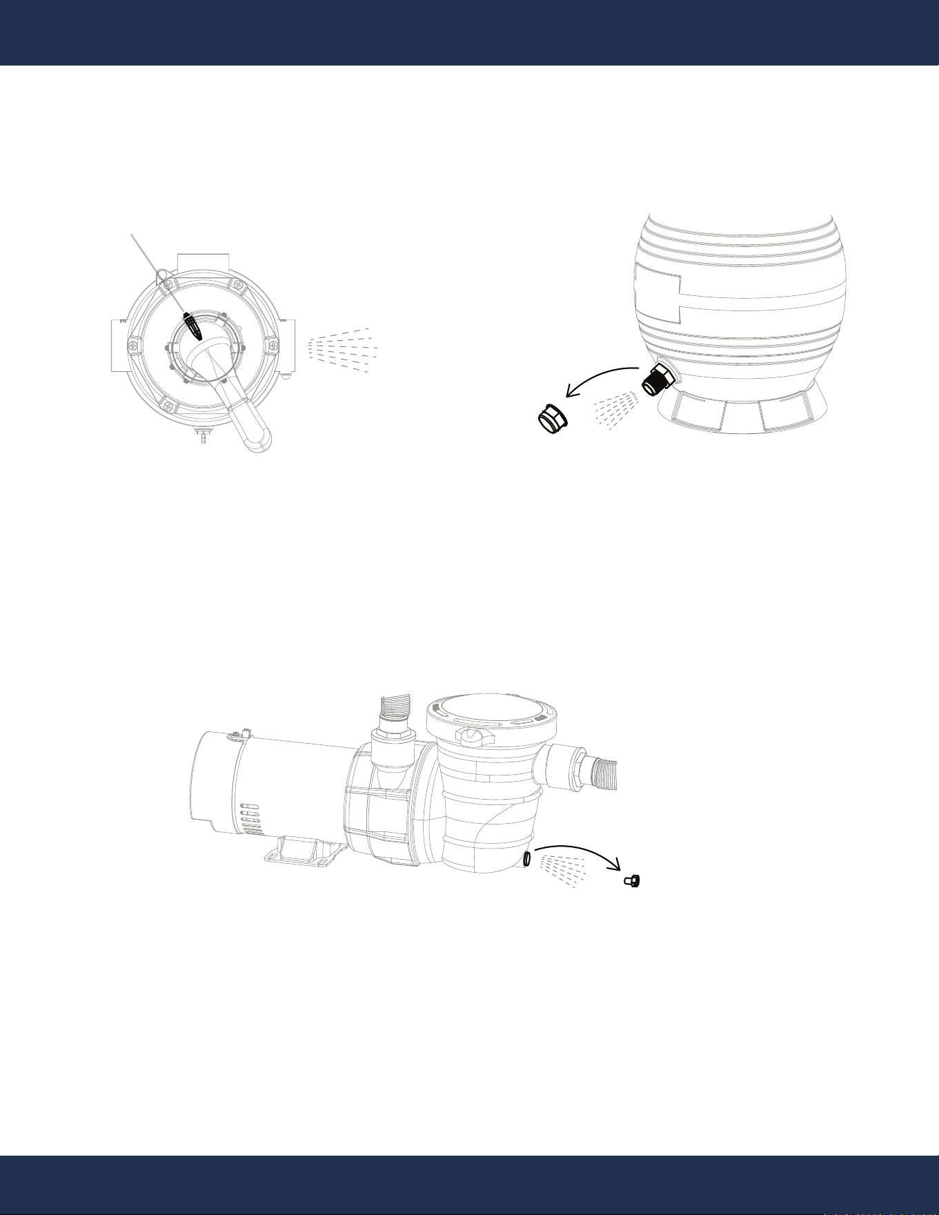
PRESSURE GAUGE
PORT PLUG
TEFLON TAPE
TEFLON TAPE
PRESSURE GAUGE PORT
PRESSURE GAUGE PORT
PARTS #
9
PARTS # 1
PARTS # 7
PARTS # 12
PARTS # 12
PARTS # 12
STEP 3
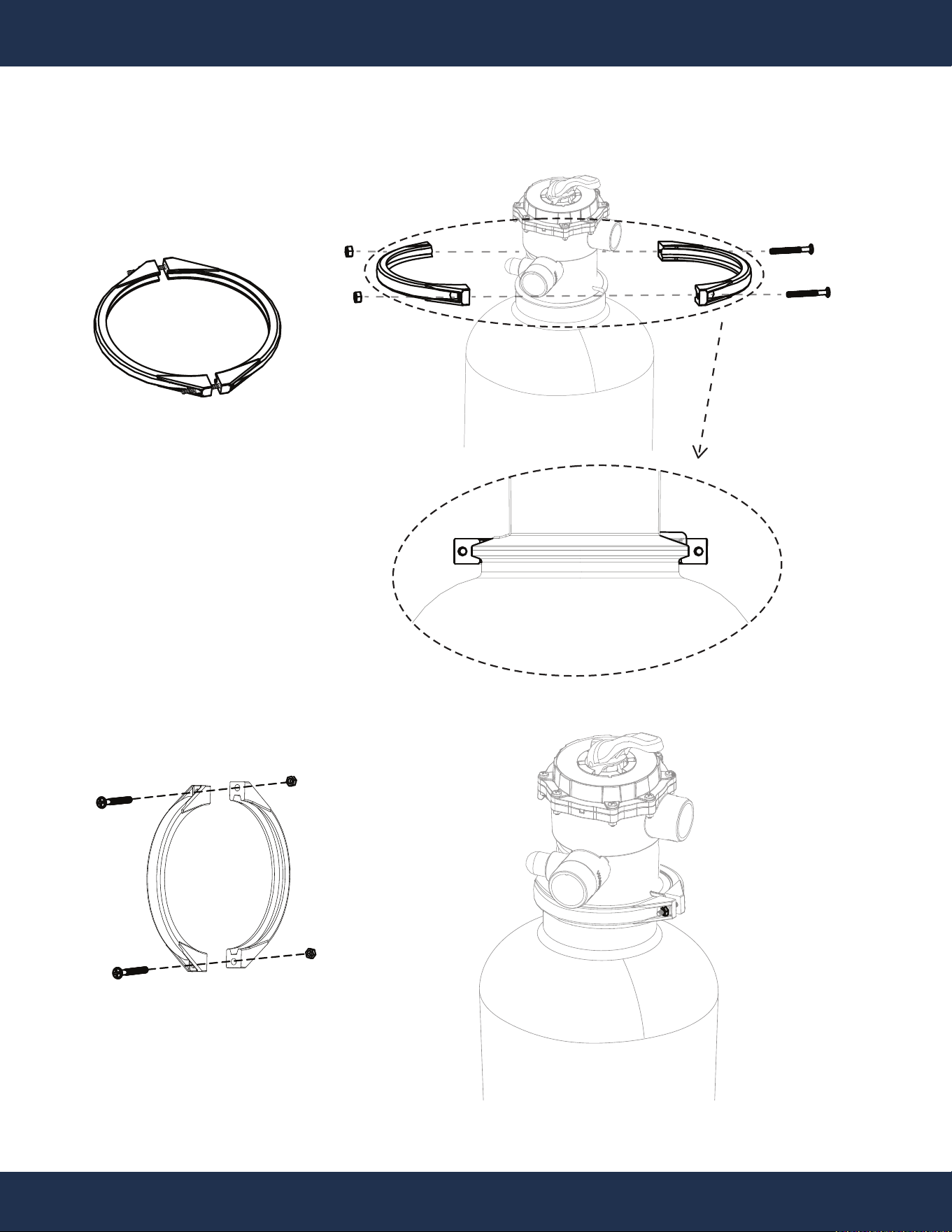
INSTALLATION
9
PARTS # 8
PARTS # 8
STEP 4
10
INSTALLATION
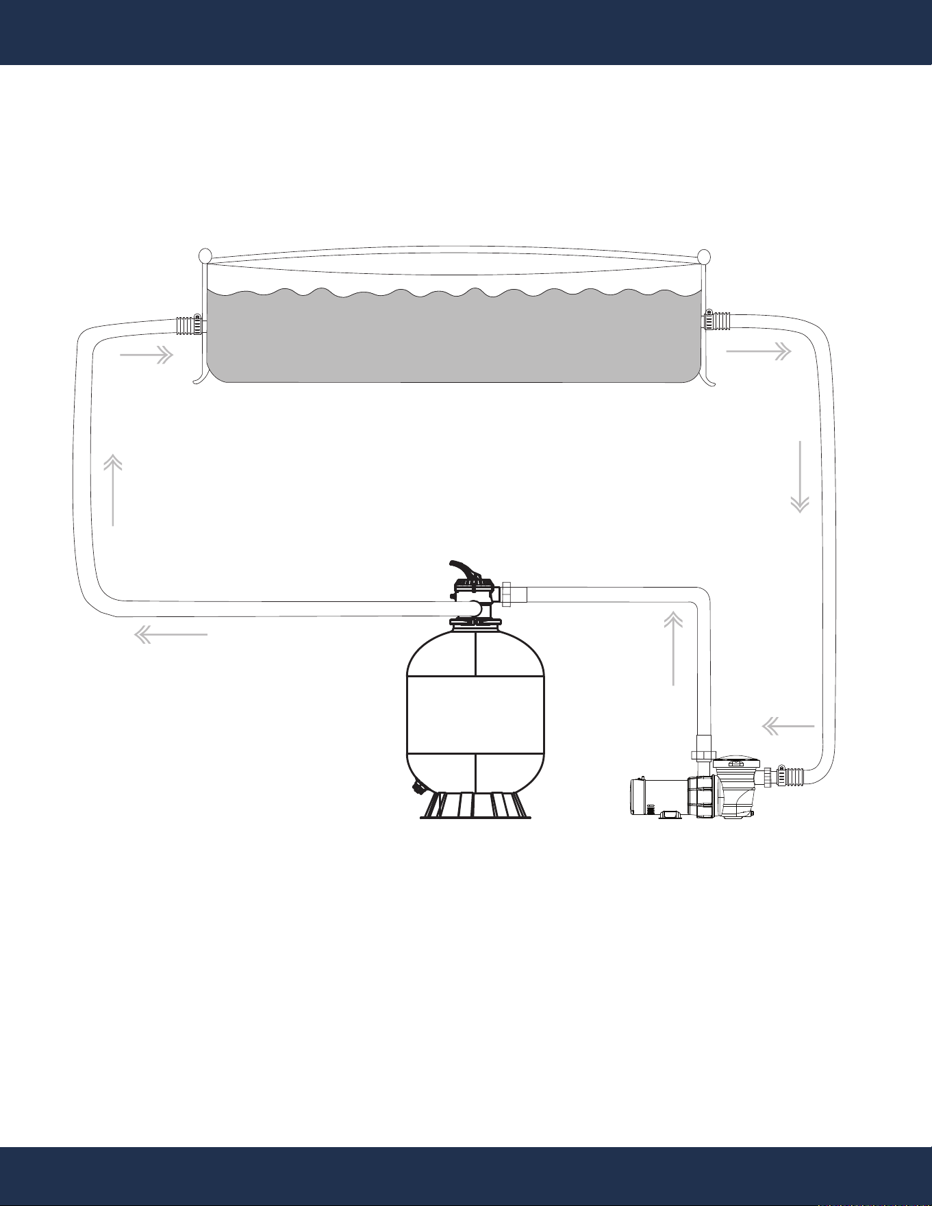
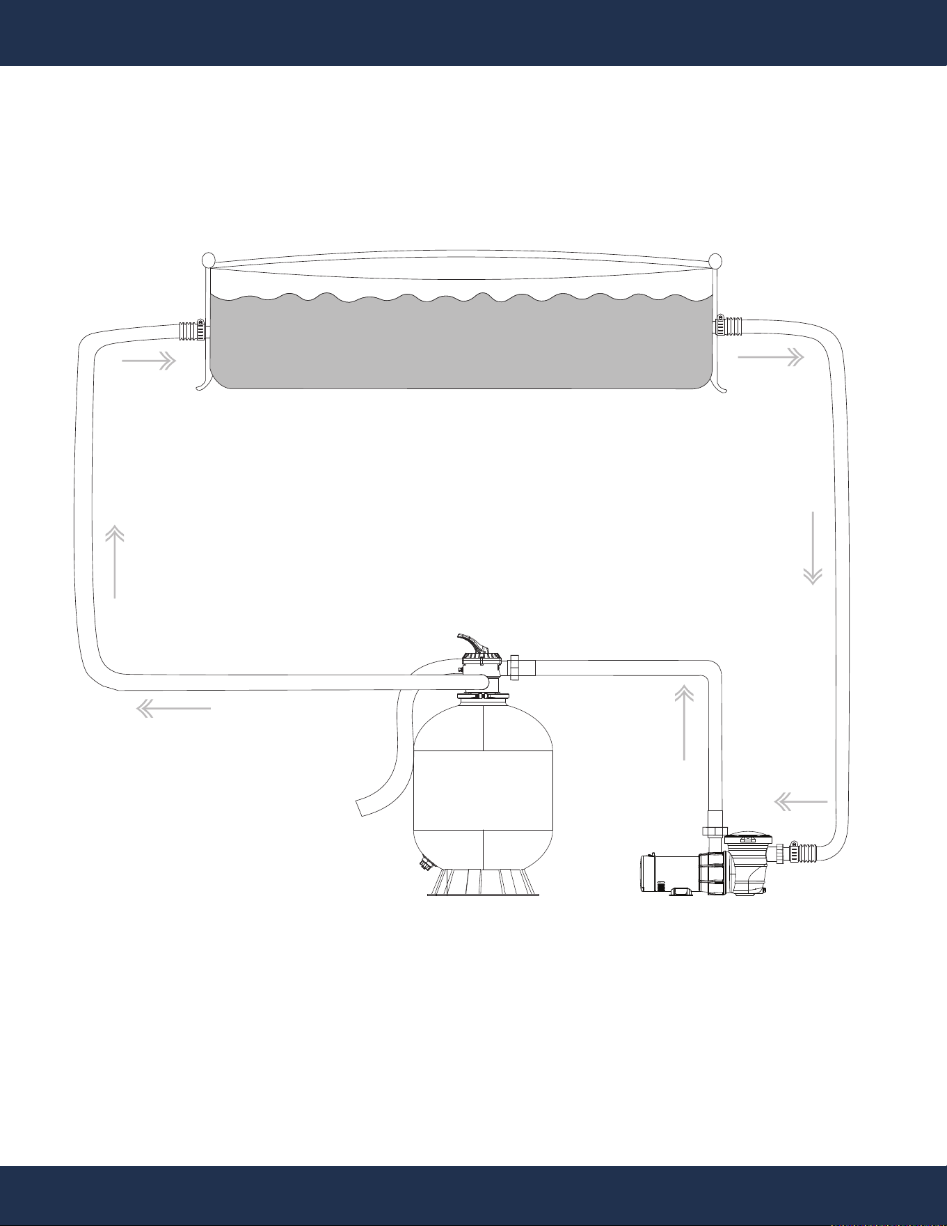
INSTALLATION LAYOUT DIAGRAM
POOL FILTER
POOL PUMP
POOL
OUTLET PORT
TO POOL
POOL
INLET PORT
FROM POOL
TO FILTER
SWIMMING POOL
FROM PUMP
11
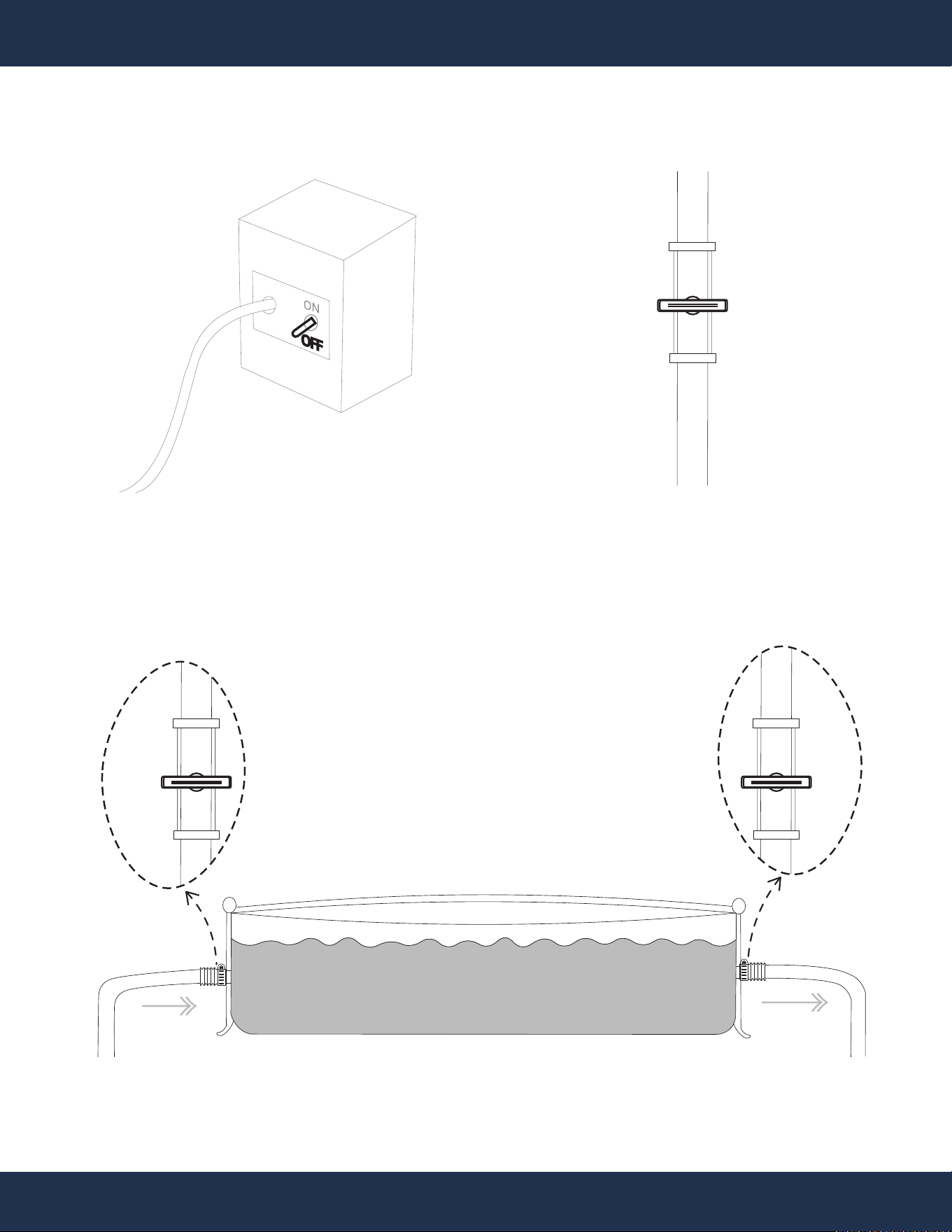
INSTALLATION
STEP 1
STEP 2
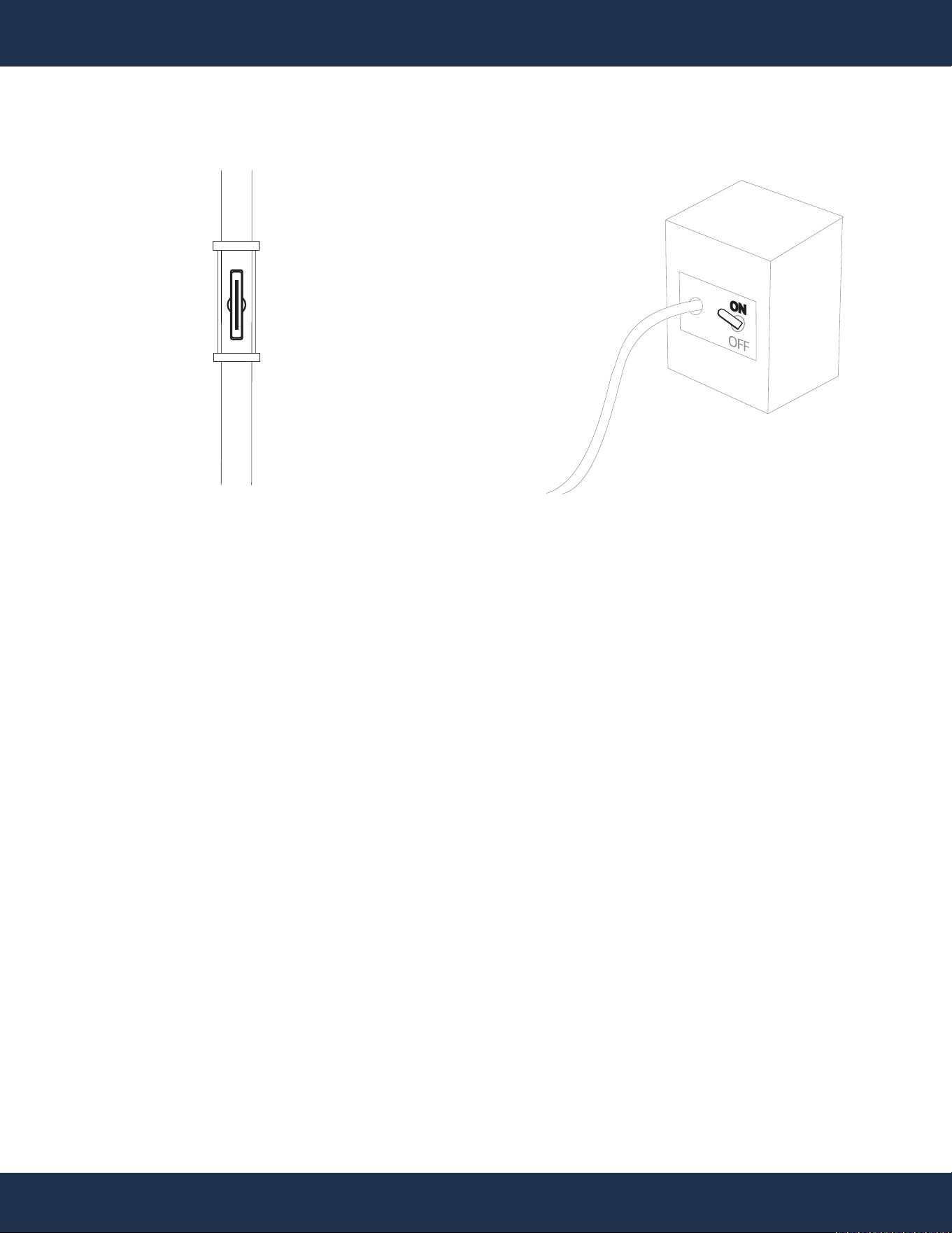
WATER FLOW VALVEELECTRIC POWER SOURCE
OFF
POOL
OUTLET PORT
POOL
INLET PORT
SWIMMING POOL
OFF
OFF
12
INSTALLATION
WASTE
WASTE
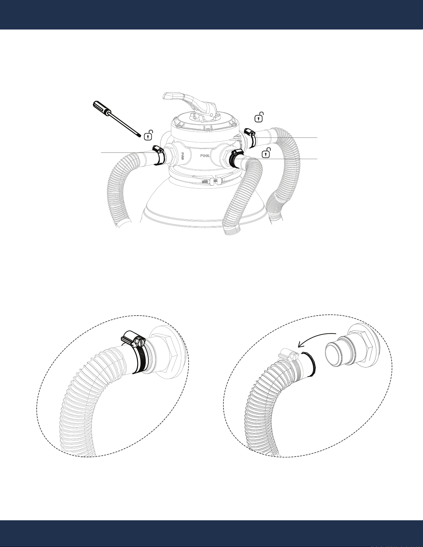
STEP 3
CONTROL VALVE ON EXISTING FILTER
WATER
WASTE
WATER
EXISTING FILTER TANK
FILTER TANK
DRAIN PORT
PUMP
DRAIN PLUG
WATER
PUMP
13
INSTALLATION
STEP 4
TO POOL
FROM PUMP
WASTE PORT
10
INSTALLATION
14
INSTALLATION
14
INSTALLATION
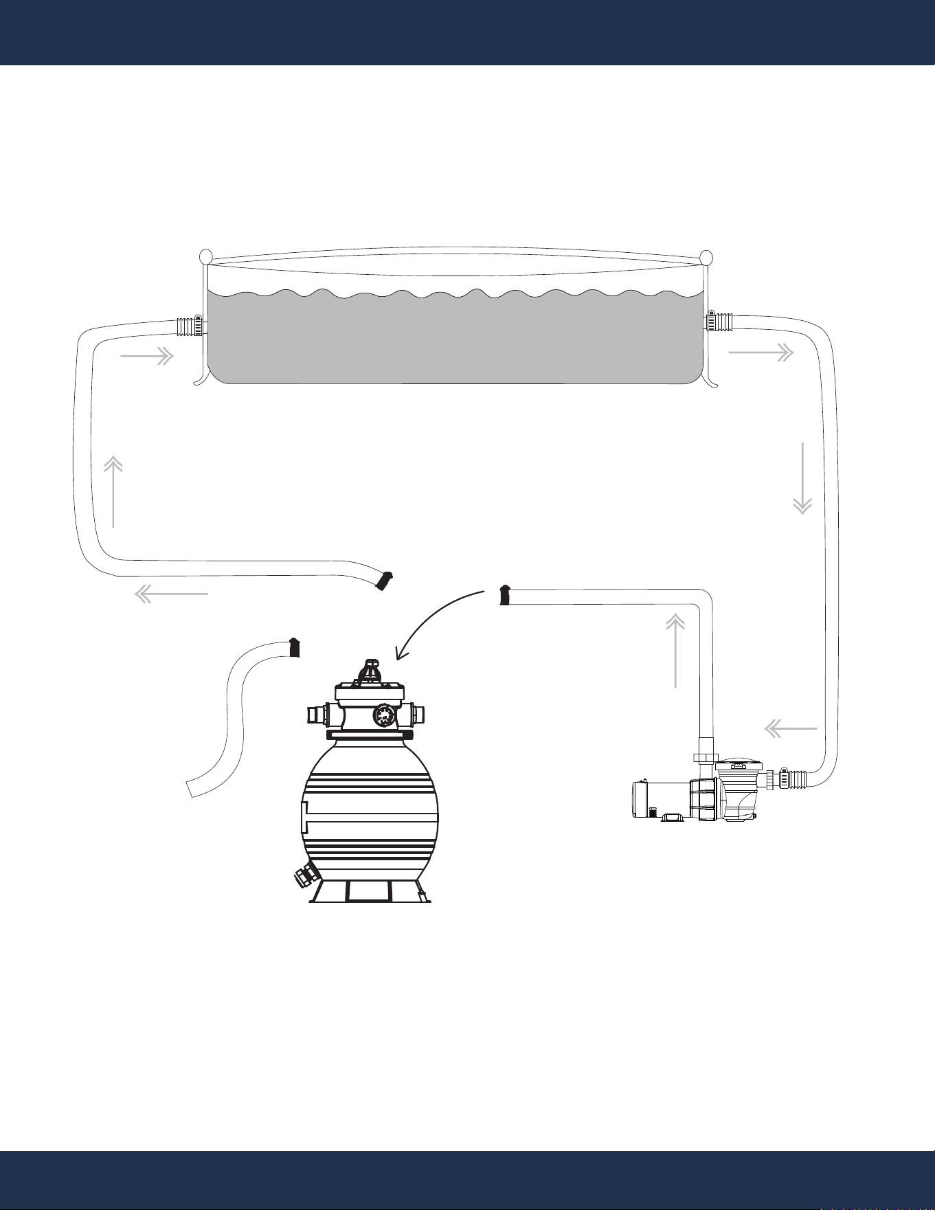
STEP 5
EXISTING FILTER
POOL PUMP
POOL
OUTLET PORT
TO POOL
POOL
INLET PORT
FROM POOL
TO FILTER
SWIMMING POOL
FROM PUMP
psi
bar
KL1.6
1
0
10
20
30
50
60
2
3
4
40
WASTE OUT
15
INSTALLATION
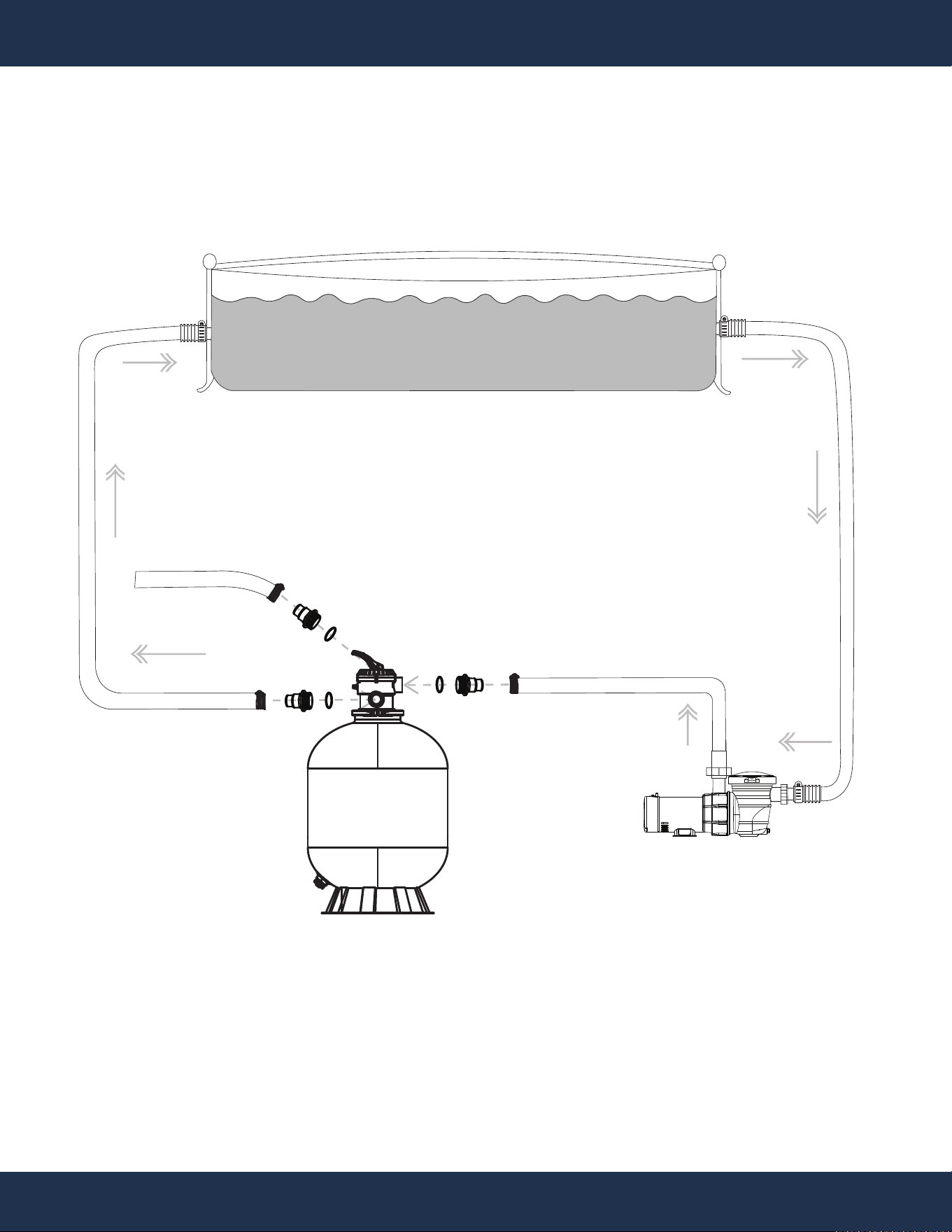
STEP 6
NEW FILTER
POOL PUMP
POOL
OUTLET PORT
TO POOL
POOL
INLET PORT
FROM POOL
TO FILTER
SWIMMING POOL
FROM PUMP
WASTE OUT
16
INSTALLATION
STEP 7
NEW FILTER
POOL PUMP
POOL
OUTLET PORT
TO POOL
POOL
INLET PORT
FROM POOL
TO FILTER
SWIMMING POOL
FROM PUMP
WASTE OUT
17
INSTALLATION
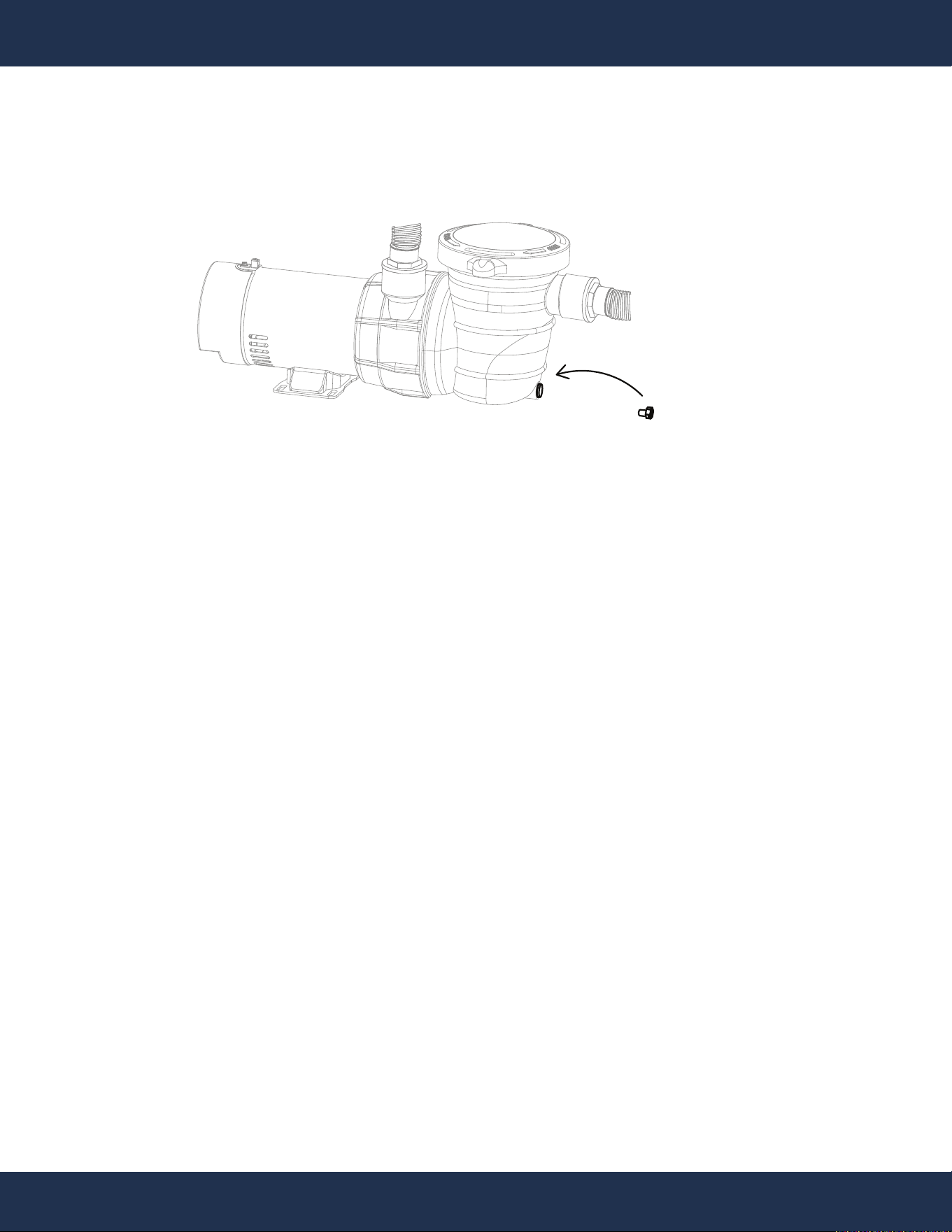
STEP 8
PUMP
DRAIN PLUG
PUMP
18
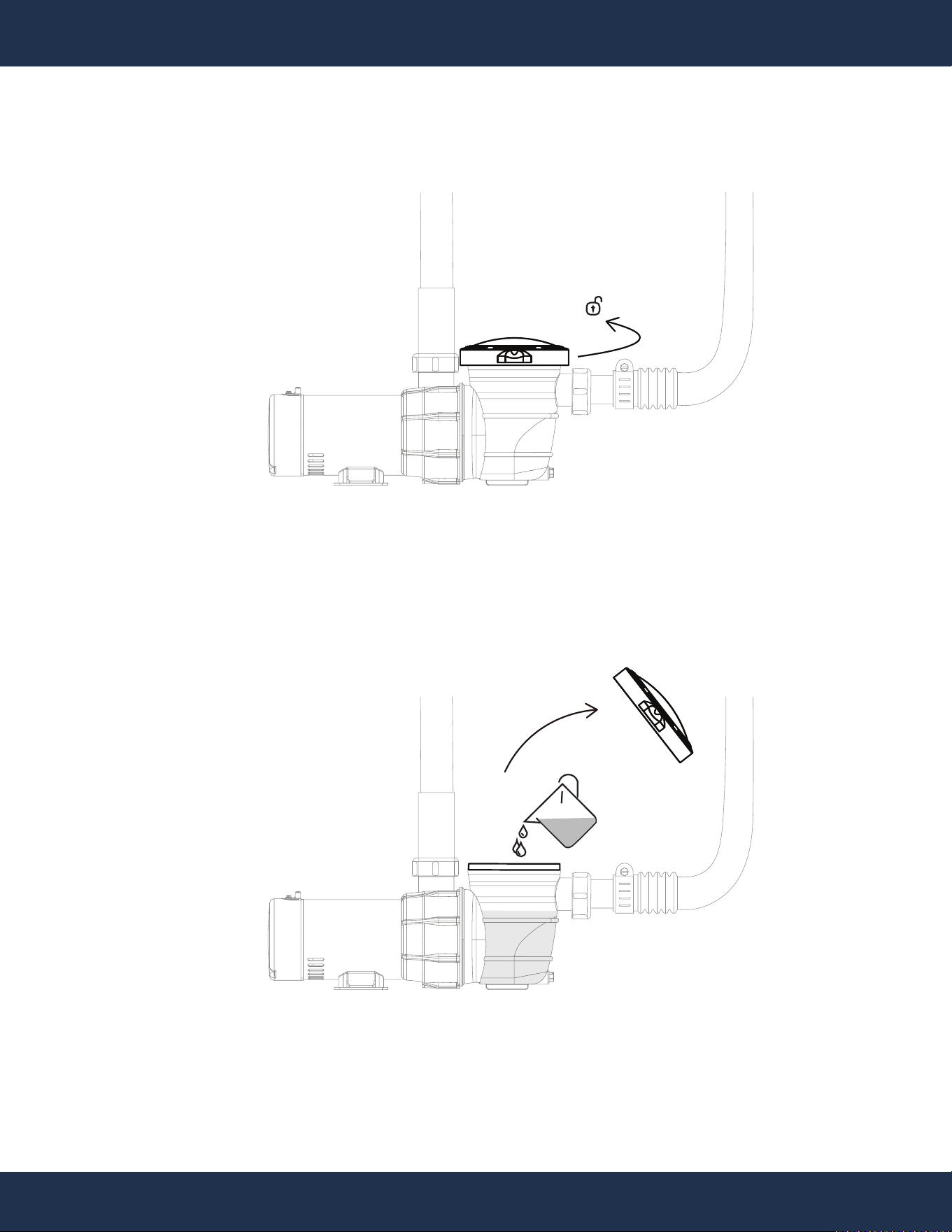
OPERATION
STEP 2
NEW POOL PUMP
STRAINER LID
NEW POOL PUMP
WATER
PRIMING THE PUMP
STEP 1
19
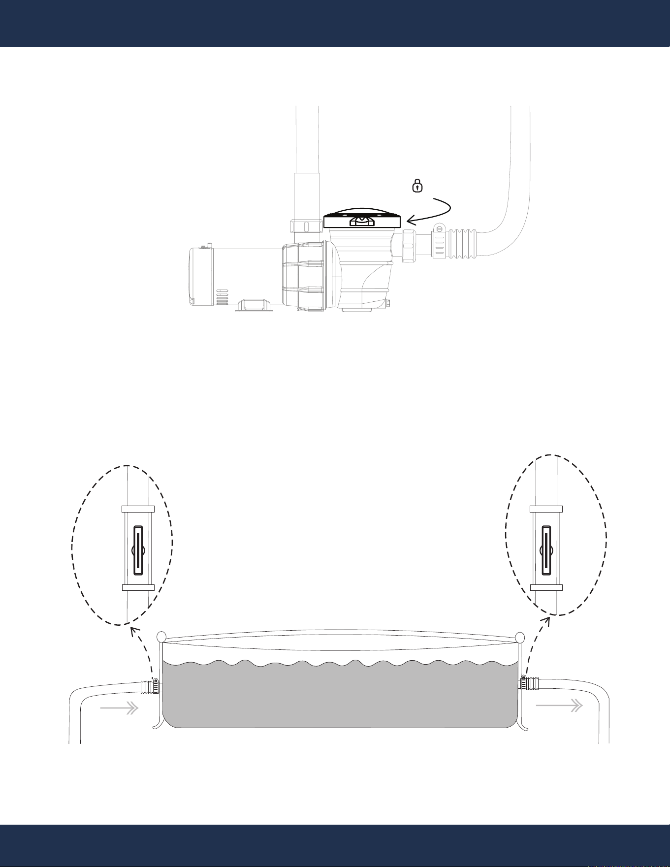
OPERATION
STEP 3
STEP 4
NEW POOL PUMP
STRAINER LID
POOL
OUTLET PORT
POOL
INLET PORT
SWIMMING POOL
ON
ON
20
OPERATION
STEP 5
WATER FLOW VALVE
ELECTRIC POWER SOURCE
ON
21
OPERATION
VALVE FUNCTIONS
STEP 1
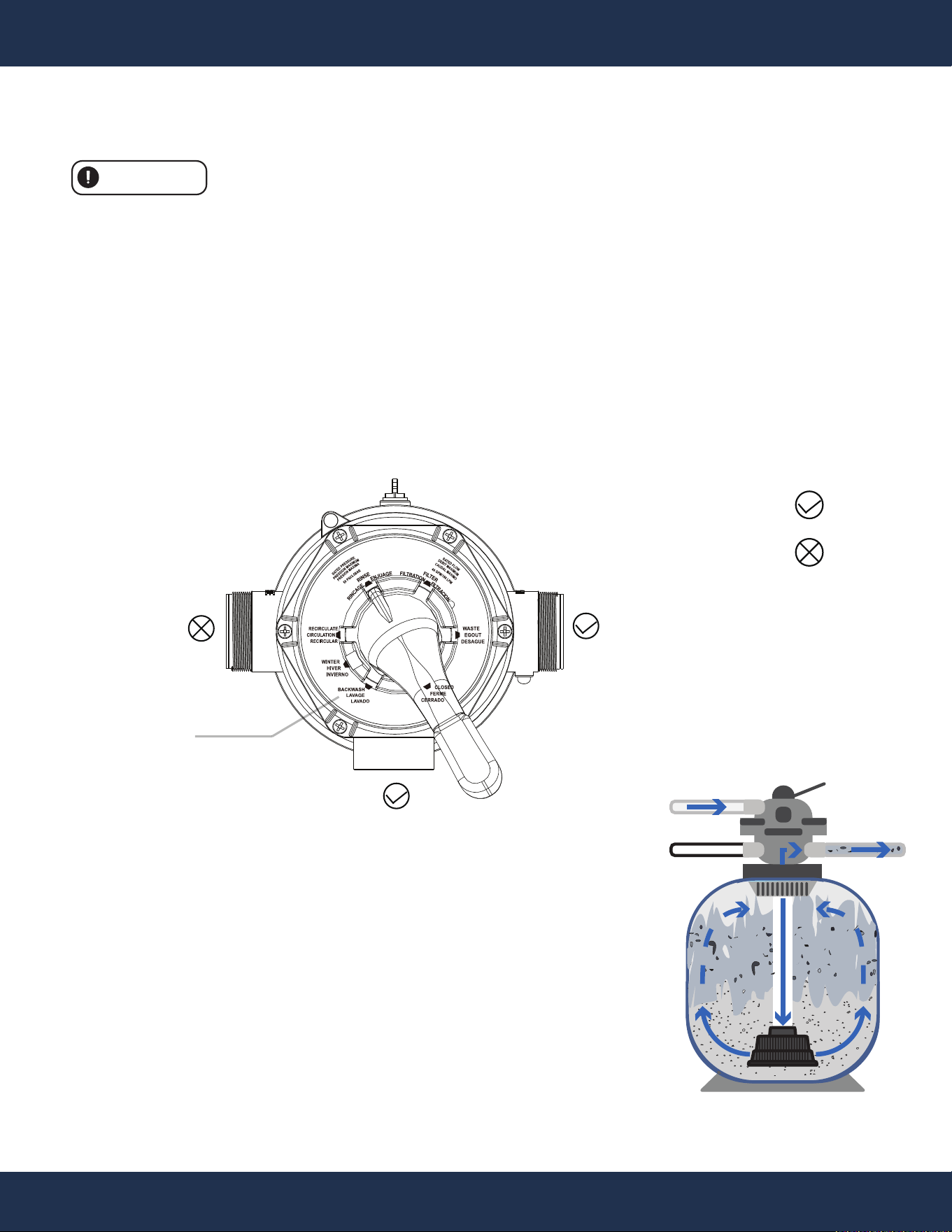
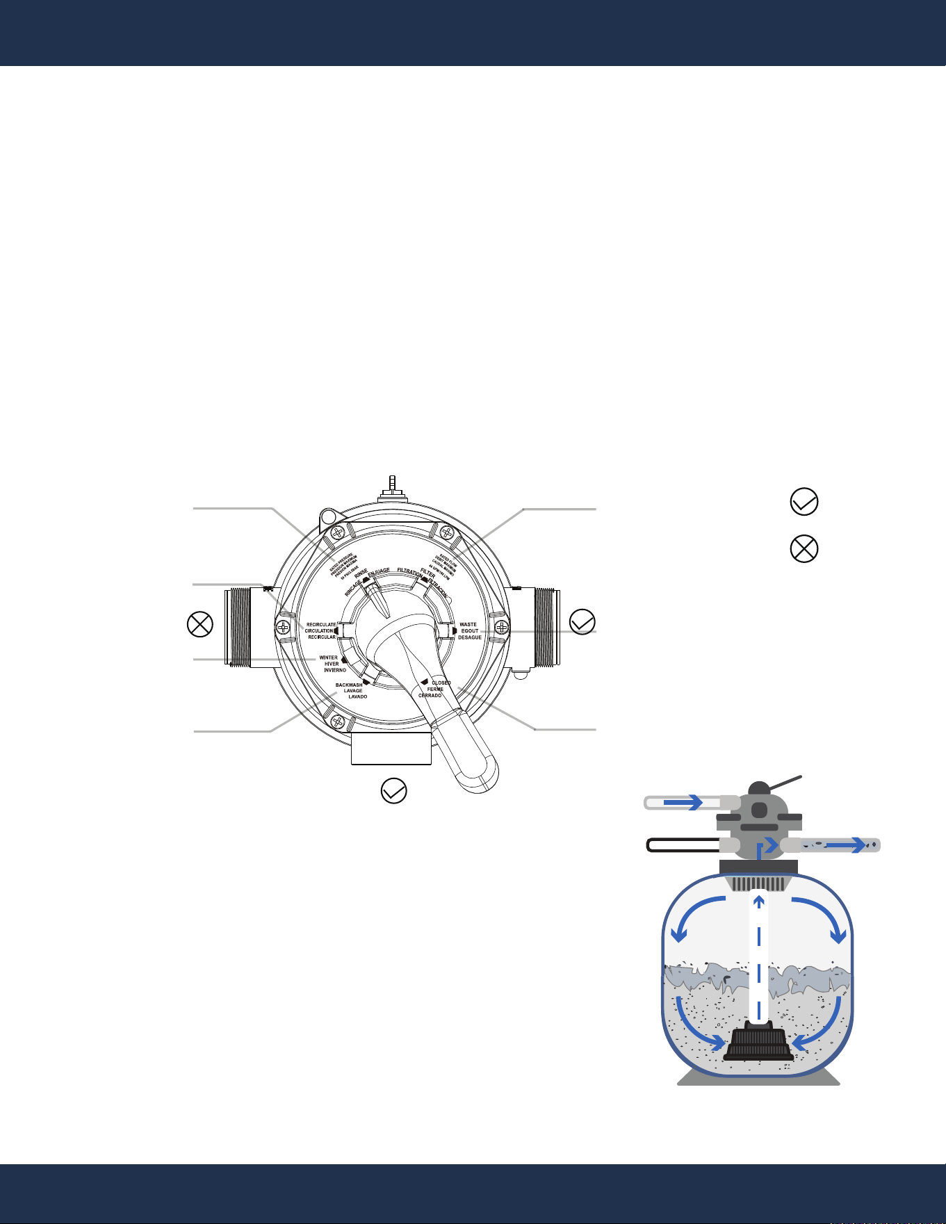
BACKWASH (Initial Run)
Use this setting to clean the filter. When the filter pressure gauge rises 5-10 PSI (0.0.34-0.69 BAR, this
reading may vary depending on the pool's pump and general piping system) above the start-up clean
pressure.
• Turn off the pump and set the valve to the "BACKWASH" position.
• Start the pump and backwash until the water in the sight glass is clear. This usually takes about 2
minutes or less, depending on the amount of dirt accumulated, and then turn off the pump.
Proceed to “RINSE”.
: Opened
: Closed
CAUTION
Never operate the pump without water.
IN
OUT
WST
Pump Line
Return Line
Waste
WASTE
PUMP
RETURN
BACKWASH

22
OPERATION
WASTE
PUMP
RETURN
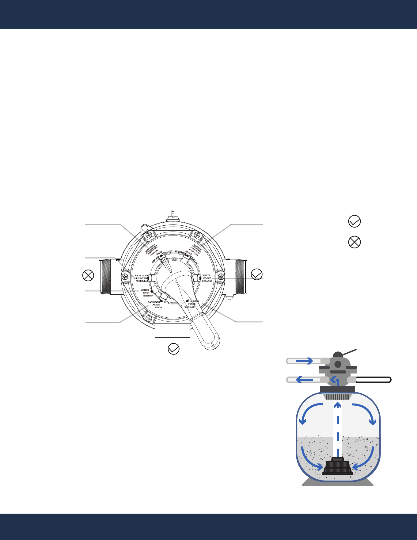
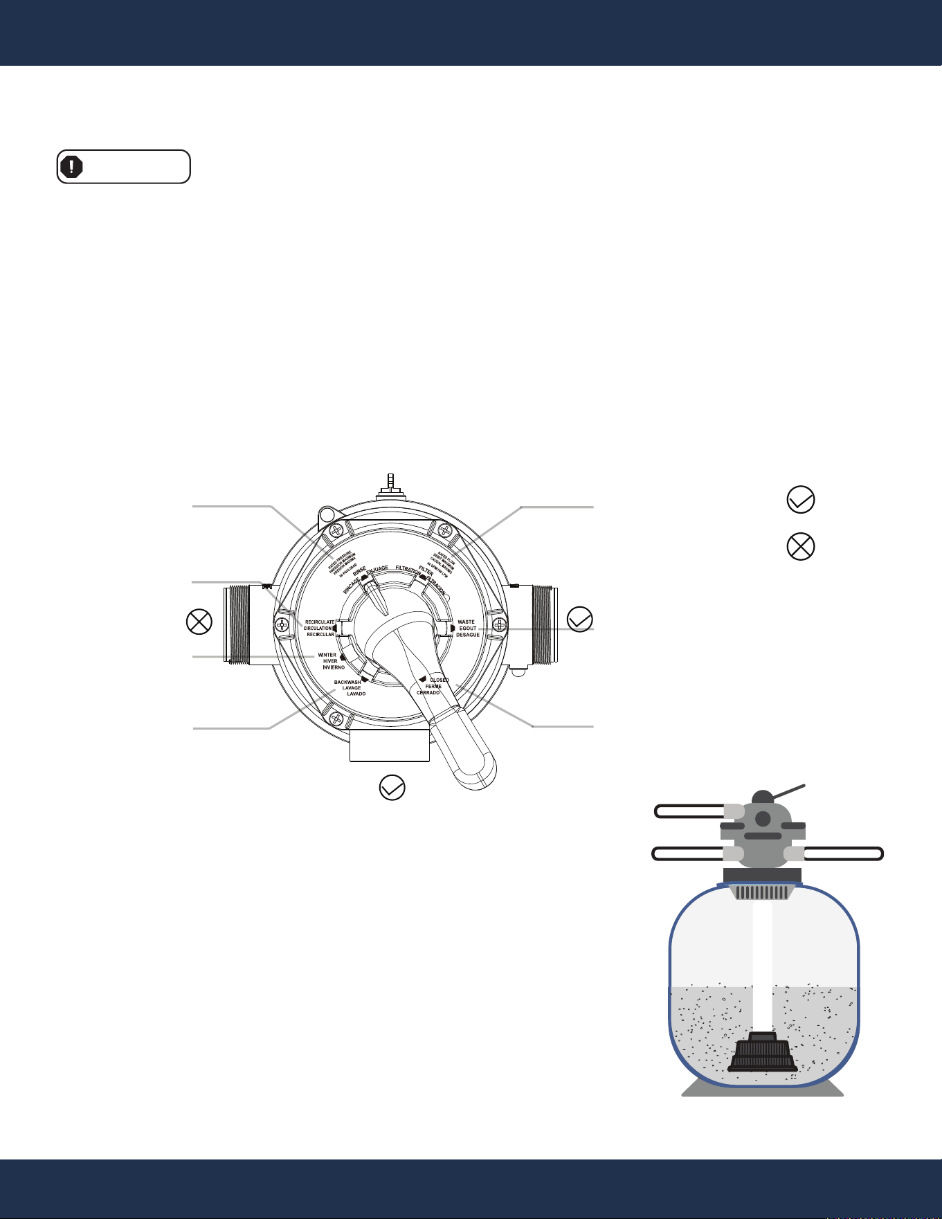
RINSE
RINSE (Initial Run)
This ensures that all the dirty water from backwashing is rinsed out of the filter and goes to waste,
preventing possible return to the pool.
• After backwashing, keep the pump off and set the valve to "RINSE" position and start the pump for
about 0.5 to 1 minute.
• During rinsing, discharge water through the drain pipe. After sufficient rinsing, stop the pump, set
the valve to “Filtration”, and start the pump for normal filtering.
: Opened
: Closed
IN
OUT
WST
Pump Line
Waste
Return Line
23
OPERATION
WASTE
PUMP
RETURN
RECIRCULATE
RINSE
WINTER
BACKWASH
FILTER
WASTE
CLOSED
: Opened
: Closed
Pump Line
Return Line
Waste
IN
OUT
WST
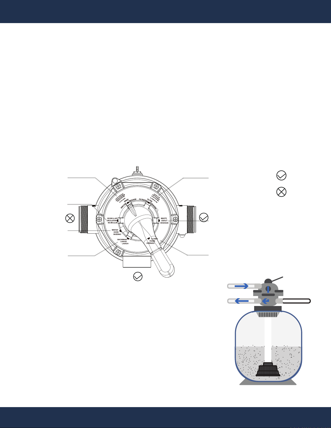
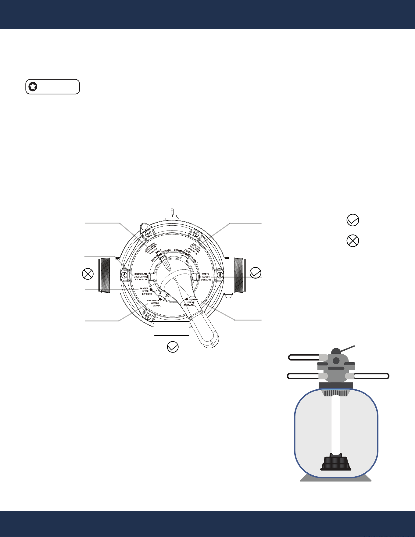
FILTER (Regular Operation)
For normal filtering and regular vacuuming.
• Turn off the pump. Set the valve to the "FILTRATION" position for regular pool filtration. Then, start
the pump.
• Occasionally check the pressure gauge to ensure pressure remains within the normal range 5-10
PSI (0.0.34-0.69 BAR), this reading may vary depending on the pool's pump and general piping
system.
• After sufficient filtration, turn off the pump.
24
OPERATION
WASTE
PUMP
RETURN
RECIRCULATE
RINSE
WINTER
BACKWASH
FILTER
WASTE
CLOSED
: Opened
: Closed
RECIRCULATE (Move The Water Around Without Filtering)
Only use the it for a short period of time when the filter is malfunctioning, there is a severe algal
bloom in the water, chemicals are being added to the pool, or after the filter has been backwashed.
• With the pump remaining off, set the valve to the "RECIRCULATE" position to circulate the pool
water without filtering it. Then start the pump.
• After sufficient circulation, turn off the pump.
Pump Line
Return Line
Waste
IN
OUT
WST
25
OPERATION
WASTE
PUMP
RETURN
RECIRCULATE
RINSE
WINTER
BACKWASH
FILTER
WASTE
CLOSED
: Opened
: Closed
WASTE (Bypass Filter Media For Direct Water Exit)
It enables water to access the filter but avoids passing through the filter media, instead directing it
to exit the filtration system entirely. It aids in extracting leaves, dirt, and additional debris.
• With the pump remaining off, set the valve to the "WASTE" position to prevent clogging of the
filter while vacuuming the pool. Then start the pump.
• After sufficient flushing, turn off the pump.
IN
OUT
WST
Pump Line
Waste
Return Line
26
OPERATION
WASTE
PUMP
RETURN
RECIRCULATE
RINSE
WINTER
BACKWASH
FILTER
WASTE
CLOSED
: Opened
: Closed
CLOSED (Shut Off The Flow To The Filter and Pool)
This function involves shutting the valve to prevent water from entering, offering utility in clearing
the lines during the pool's opening process and during winterization to expel air through the suction
lines, redirecting airflow into the pool.
• With the pump remaining off, set the valve to the "CLOSED" position to prevent water from
entering.
Avoid activating the pool pump when the 7-way valve is set to CLOSED, as this could result in
damaging the filter, the pump, or both.
WARNING
Pump Line
Return Line
Waste
IN
WST
OUT
27
OPERATION
WASTE
PUMP
RETURN
RECIRCULATE
RINSE
WINTER
BACKWASH
FILTER
WASTE
CLOSED
: Opened
: Closed
Pump Line
Return Line
Waste
IN
WST
WINTER (For Winterizing)
Separate bonding surfaces to prevent freezing damage.
Clearing out all residual water will reduce the risk of freeze damage.
• Setting the Valve for Winterization
◦ With the pump remaining off, set the valve to the "WINTER" position to open all ports to prevent
residual water inside the machine from freezing and causing damage.
NOTE
OUT

28
OPERATION
DANGER
WINTER (For Winterizing) (Continued)
Before attempting any corrective actions, ensure that the pump is in the OFF position. To avoid any
potential electrical hazards, wait until the remaining power in the capacitor is fully discharged before
proceeding with any work on the pump.
• Storing Pump for Winterization
◦ Turn off the power for the pump.
◦ Drain Water.
▪ For Sand Filter
- Turn the valve to “BACKWASH” for 3 to 5 minutes.
- Set the valve to “WINTER” position.
▪ For Cotton Ball Filter
- Turn off the pool pump power.
- Locate and open the drain valve at the bottom of the filter tank.
- Allow the water to drain from the filter.
- Close the drain valve once draining is complete.
- Set the valve to “WINTER” position.
◦ Cover the motor to shield it from severe rain, snow, and ice.
◦ Avoid wrapping the motor in plastic, as it can lead to condensation and rust on the inside of the
motor.
15
INSTALLATION
29
Before attempting any corrective actions, ensure that the pump is in the OFF position, and the
breaker supplying power to the pump is also turned OFF. To avoid any potential electrical hazards,
wait until the remaining power in the capacitor is fully discharged before proceeding with any work
on the pump.
ISSUE CAUSE CORRECTIVE ACTION
Pump Won’t Start
Improper or loose wiring
connections; open
switches or relays
Check all connections.
Tripped circuit breakers Reset tripped breakers.
Blown fuses.
Replace blown fuses in the Circuit Breakers
(Applies to older homes).
Mechanical binding and
electrical overload
Manually check rotation of motor shaft for free
movement with no obstruction.
Using a pump timer
If using a pump timer try overriding, it to ensure the
pump is receiving power. Also check the rocker
switch on the back of the pump to confirm the power
is on either high or low speed so that the timer can
turn the pump on
and off to the set speed.
Pump Starts then
Stops
Undersized wiring
Contact qualified professional to check that the
wiring gauge is heavy enough. The wiring should
be at least AWG14.
Loose connections Check all connections.
Low voltage at motor or
power drop (frequently
caused by undersized
wiring or extension cord
use)
Contact qualified professional to check that the
wiring gauge is heavy enough. The wiring should
be at least AWG14.
Overheating
The pump shouldn't be running for more than 8
hours a day. Ensure that it is either well shaded or
run during the cooler times of the day to prevent the
bearings from drying out quickly.
Mechanical binding
Manually check rotation
of motor shaft for free
movement with no obstruction.
Electrical overload
Ensure proper grounding and wiring voltage.
DANGER
TROUBLESHOOTING
TROUBLESHOOTING
30
ISSUE CAUSE CORRECTIVE ACTION
Pump Hums but
will Not Start
Incorrect Voltage Check input voltage and wiring connection.
Incorrect Wiring Check wiring connections.
Mechanical binding
Manually check rotation of motor shaft for free
movement with no obstruction.
Ensure that the pump is properly primed before its
first use. Also, check for any leaks at the
connections or in your pipes. The pump basket
should always be full while the pump is running;
Capacitor failure
Have the capacitor tested by a pool pump repair
company.
Pump Won’t
Prime
Pump Ran Dry
Pump Ran Dry
Ensure that the pump is properly primed be
fore its
first use. Also, check for any leaks at the
connections or in your pipes. The pump basket
should always be full while the pump is running;
any loss of water in the basket while running or
when the pump turns off indicates a leak
somewhere.
A backflow device can be installed in the suction line
Empty pump/strainer
housing.
Make sure pump/strainer housing is filled with water
and cover O-ring is clean. Ensure O-ring is properly
seated in the cover O-ring groove. Ensure O-ring is
lubricated, and that strainer cover is locked firmly in
position. Lubricant will help to create a tighter seal.
Lubricant will help to create
a tighter seal. Fill with
Loose connections on
suction side and/or outlet
side.
Tighten pipe/union connections. (Any self-priming
pump will not prime if there are suction air leaks.
Leaks will result in bubbles emanating from return
fittings on the pool wall or in the strainer basket.)
Leaking O-ring or packing
glands on valves.
Tighten, repair, or replace valves.
Strainer basket or
skimmer basket loaded
with debris.
Remove strainer housing cover or skimmer cover,
clean basket, and refill strainer housing with water.
Tighten cover.
of the pool pipes if needed.
water and observe carefully to check for any leaks.
TROUBLESHOOTING
31
ISSUE CAUSE CORRECTIVE ACTION
Suction side clogged.
Contact a qualified repair professional.
if pump will develop a vacuum. You should have 5”-
6” of vacuum at the strainer cover (Only your Pool
dealer can confirm this with a vacuum gauge).You
may be able to check by removing the skimmer
basket and holding your hand over the bottom port
with skimmer full and pump running. If no suction is
felt, check for line blockage.
1) If pump develops a vacuum, check for blocked
suction line or dirty strainer basket. An air leak
in the suction piping may be the cause.
2) If pump does not develop a vacuum and pump
has sufficient “
priming water”:
a. Re-check strainer housing cover and all
threaded connections for suction leaks.
system hose clamps are tight.
b. Check voltage to ensure that the motor is
c. Open housing cover and check for
clogging or obstruction in suction.
Check impeller for debris. Remove and
replace shaft seal only if it is leaking.
rotating at full RPM’s.
Low Flow
Clogged or restricted
strainer or suction line
and/or outlet line.
Contact a qualified repair professional.
The pump's location is
either too high above the
pool water level and/or
too far from the pool.
Make sure that the pump height and lines are not
fu
rther than the manufacturer's recommended
maximum distance.
Undersized pool piping. Correct piping size.
Plugged or restricted
discharge line of filter,
valve partially closed
(high gauge reading).
Sand filters – backwash as per manufacturer’s
instructions; D.E. filters – backwash as per
manufacturer’s instructions; Cartridge filters – clean
or replace cartridge.
Block off the bottom port of the skimmer to determine
Disconnect from the breaker and check if all
Pump Won’t
Prime (Cont)
TROUBLESHOOTING
32
ISSUE CAUSE CORRECTIVE ACTION
Air leak in suction
(bubbles issuing from
return fittings).
Re-tighten using Teflon tape.
Plugged, restricted, or
damaged impeller.
Clear blockage and replace the impeller seal.
Noisy Pump
Air leak in suction piping,
cavitation caused by
restricted or undersized
suction line or leak at any
joint, low water level in
pool, and unrestricted
discharge return lines.
Correct suction condition or throttle return lines, if
practical. Holding hand over return fitting will
sometimes prove this point or putting in a smaller
eyeball fitting.
Vibration due to improper
mounting, etc.
Mount the pump on a level surface and secure the
pump to the equipment pad.
Foreign matter in pump
housing. Loose
stones/debris hitting
impeller could be cause.
Clean the pump housing.
Squealing sounds that
are getting louder over
time
Bearings may become noisy over time if not
properly maintained. They can be re-greased and
should be done with regular pump maintenance,
depending on usage. Check for leaks in the seals
that may allow water, including chemicals, to work
into the bearing ring and wipe out the grease. Any
leaking seals should be replaced at once.
Low Flow
(Cont)
Contact a qualified repair professional.
TROUBLESHOOTING
33
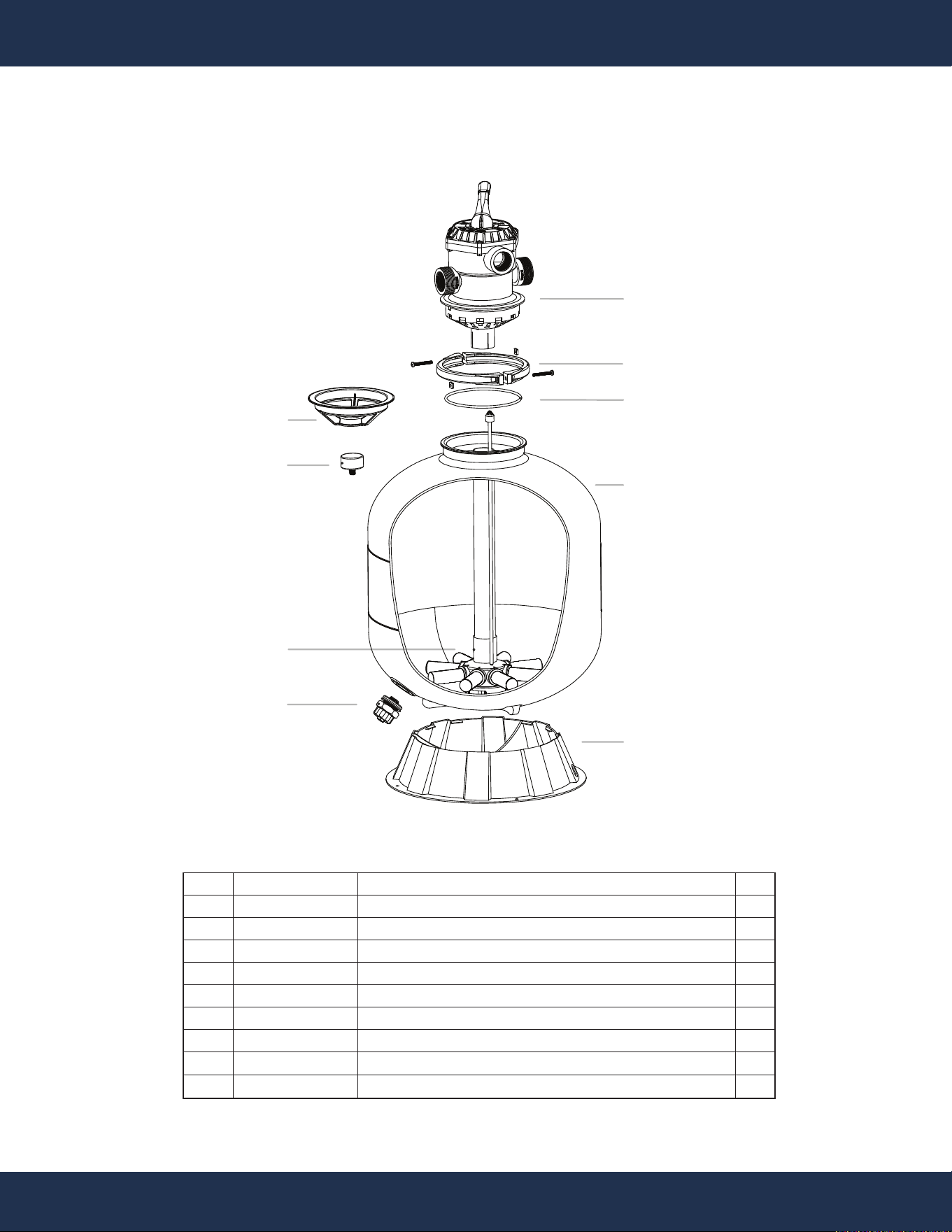
REPLACEMENT PARTS
REPLACEMENT PARTS
PARTS DIAGRAM
ITEM
1
2
3
4
5
6
7
8
9
REFERENCE #
647304071000
647304072000
5431012080
47305408906
47305009080
647304073000
647305472001
5024002000
47304023080
DESCRIPTION
7-WAY VALVE
FLANGE CLAMP
LARGE O-RING Φ174xΦ5.5
FILTER TANK
FILTER TANK BASE 19”
DRAIN PLUG SET
MEDIA ASSEMBLY W/ AIR RELEASE & LATERAL
GAUGE MAX SCALE 60PSI/4BAR
FUNNEL
QT
Y
1
1
1
1
1
1
1
1
9
5
4
8
3
1
2
6
7

DISCLAIMER
PLEASE READ THE FOLLOWING CAREFULLY
The manufacturer and/or distributor have provided the parts list and assembly diagram in this
manual for reference purposes only. They do not make any representation or warranty to the buyer
that they are qualified to make repairs to the product or replace any parts of the product. In fact, the
manufacturer and/or distributor expressly state that all repairs and parts replacements should be
undertaken by certified and licensed technicians, and not by the buyer.
The buyer assumes all risk and liability arising from their repairs to the original product or
replacement parts or arising from their installation of replacement parts. It is strongly advised that
qualified professionals handle any repairs or replacements to ensure safety and proper functioning
of the product. Improper installation and operation may result in injury, property damage, or voiding
of warranty. The manufacturer and/or distributor shall not be held responsible for any accidents,
damages, or malfunctions resulting from the buyer's installation and operation of the product. It is
essential to follow all safety guidelines and recommendations provided in this manual and to seek
professional assistance if unsure about the installation or operation procedures.
CUSTOMER SERVICE
If you have any questions about ordering our pool pumps and replacement parts or pool products,
please feel free to contact us using the following contact information:
Customer Service and Technical Support
Phone: (909) 628-0880
Email: [email protected]
Hours of Operation: Monday – Friday, 9AM – 4PM (CST)
34
DISCLAIMER
