Thank you for purchasing this product! If you have any question about the product
such as missing parts, damaged products, product assembling, operation, etc., please
contact us via our customer service phone: 213-4467172 or 661-4358826.
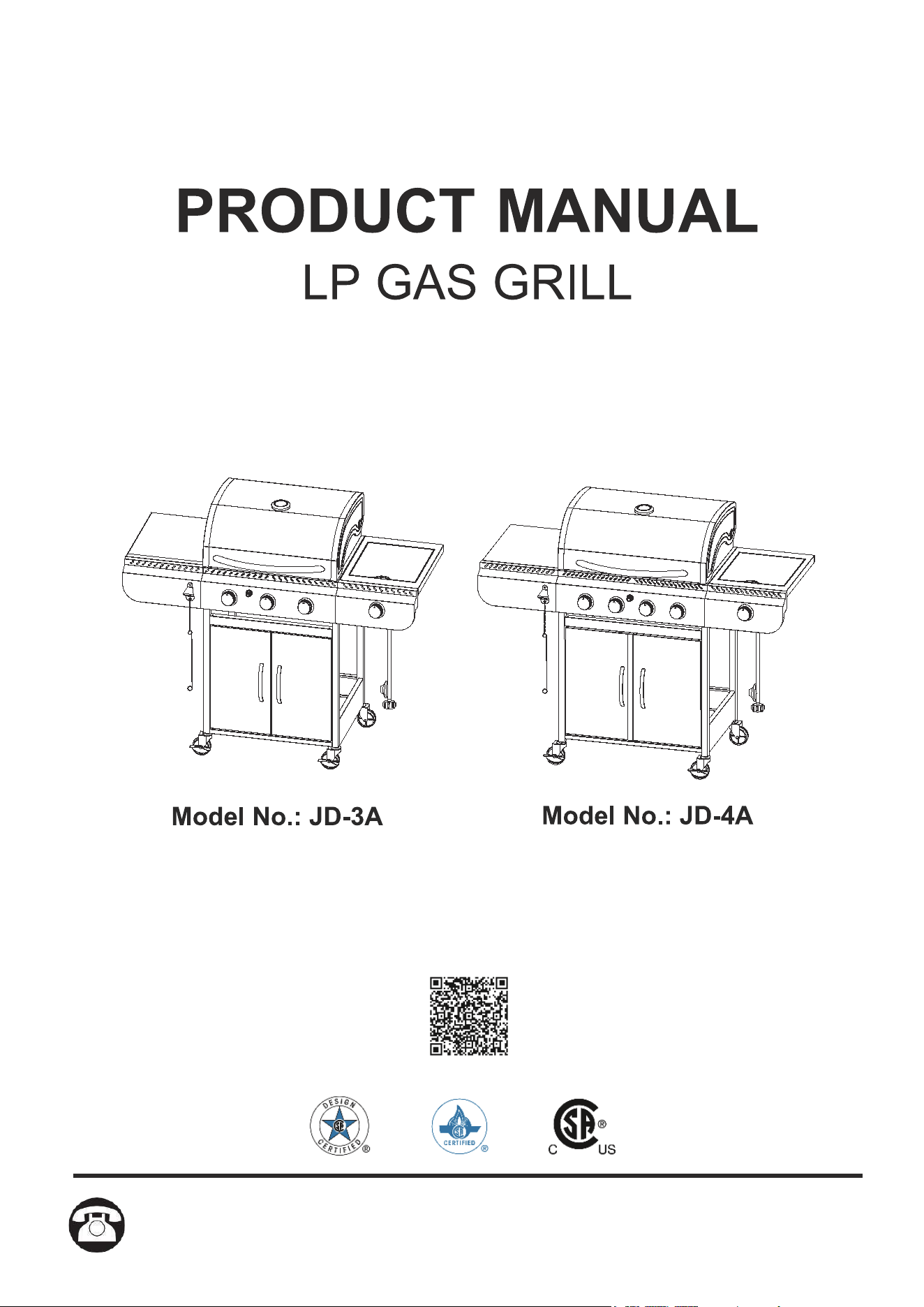
NOTE:The pictures are for reference only, the actual product shall prevail.
Scan the QR code to watch the installation video.
818-468-1498
818-468-1498.818-468-1498.818-468-1498.818-468-1498.818-468-1498.818-468-1498.
818-468-1498.
TABLE OF CONTENTS
Safety Information ................................................................................................................. ..........1
Package Contents ...........................................................................................................................3
Preparation ......................................................................................................................................4
Assembly Instructions ....................................................................................................................4
Operation Instructions ................................................................................................................... 20
Care and Maintenance ..................................................................................................................25
Troubleshooting .............................................................................................................................28
Consumer/User: Follow all warnings and instructions when using this appliance.
Assembler/Installer: This manual contains important information that is necessary for the
proper assembly and safe use of this appliance. Read and follow all warnings and instructions
before assembling and using this appliance. Leave these instructions with the consumer.
Retain these instructions for future reference.
WARNING
DANGER
1.Do not store or use gasoline, vapors,
or other flammable fluids close to this
or any other appliance.
2.An LP cylinder not connected for use
shall not be stored in the vicinity of this
or any other appliance.
3.This grill is only for outdoor use and
shall not be used in a building, garage,
under overhangs or any other enclosed
area.
4.Do not leave a lit grill unattended.
Keep children and pets away from the
grill at all times.
If you smell gas:
1.Cut off the gas to the appliance.
2. Extinguish any open flame.
3.Open the lid.
4. If the odor continues, keep away
from the appliance and immediately
call your local fire department.
1
mbustion of such fuels contain
chemicals, including Benzene, known to the State of California to cause cancer, birth defects or
other reproductive harm. This product contains chemicals, including lead and lead compounds,
known to the State of California to cause cancer, birth defects or other reproductive harm. Wash
hands after handling.
CALIFORNIA PROPOSITION 65
DANGER
• Do not use in an explosive atmosphere. Keep grill area clear and free from combustible
SAFETY INFORMATION
CAUTION
• Do not use gasoline, kerosene or alcohol for lighting.
• The LP gas cylinder used with this appliance must be:
• Never keep a filledcontainer in a hot car or car trunk. Heat will cause the gas pressure to
increase, may open the relief valve and leak the gas.
• Always open grill lid slowly and carefully as heat and steam trapped within the grill can hurt
you severely.
•
Thank you for purchasing this product! If you have any question about the product
such as missing parts, damaged products, product assembling, operation, etc., please
contact us via our customer service phone: 213-4467172 or 661-4358826.
Never use charcoal or lighter fluid with the grill.
(a) Constructed and marked in accordance with the Specifications for LP-Gas Cylinders
of the U.S. Department of Transportation (D.O.T.) or the National Standard of Canada,
CAN/CSA-B339, Cylinders, Spheres and Tubes for Transportation of Dangerous Goods;
and Commission, as applicable; and
(b) Provided with a listed overfilling prevention device.
(c) Provided with a cylinder connection device compatible with the connector for outdoor
cooking appliances.This grill is not intended to be used in or installed on recreational
vehicles and/or boats.
(d) The marked cylinder water capacity or LPG capacity (in pounds) as stated by the
cylinder manufacturer(s).
2
SAFETY INFORMATION
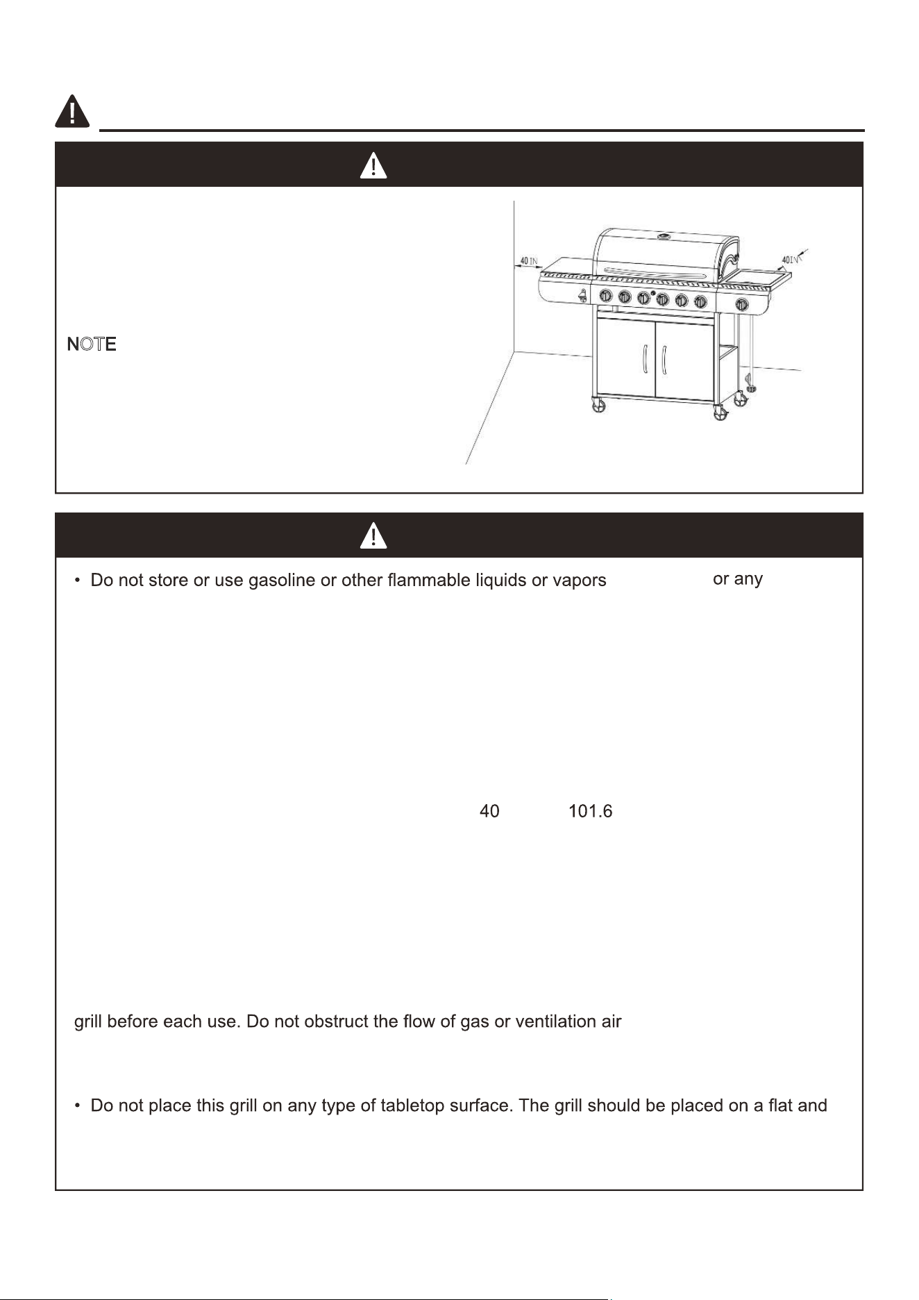
Do not place the grill under overhead combustible
construction or awnings.
The minimum clearance between the side/back of
the unit and any other construction is 40 inches
(1016.0 mm).
N
OTE: The installation must conform with local
codes or, in the absence of local codes, with
either the National Fuel Gas Code, ANSI Z223.1/
NFPA54, Natural Gasand Propane Installation
Code, CSAB149.1, or Propane Storage and
Handling Code, B149.2.
WARNING
CAUTION
other appliance.
• The use of alcohol, prescription or non-prescription drugs may influence the operator’
s ability
to properly assemble or safely operate the grill.
• Do not leave a lit grill unattended. Keep children and pets a
w
ay from the grill at all times.
level surface.
•
Do not use the grill in strong winds.
close to this
• An LP cylinder not connected for use shall not be stored close to this or any other
appliance.
• This grill is for using with propane gas only (proane cylinder not included).
• Never attempt to attach this grill to the self-contained propane system of a boat, camper trailer,
motor home or house.
• Do not attempt to move the grill while it is lit or when it is hot. The casters should be locked
down when not moving the grill.
• Do not use the grill unless it is completely assembled and all parts are securely fastened and
tightened.
• Keep all combustible items and surfaces at least
inches ( cm) away from the grill at all
times.
•
• Do not touch metal parts of grill until it has completely cooled (about 45 minutes) to avoid
burns, unless you are wearing protective gear (pot holders, gloves, BBQ mittens, etc.).
Do not alter this grill in any manner.
• Clean and inspect the hose before each use. If there is obvious abrasion, wear
, cuts, or
leaks,
the hose must be replaced prior to operating the appliance. The replacement hose assembly
shall be that specified by the manufacturer.
• Move gas hoses as far away as possible from the hot surfaces and dripping hot grease.
• Keep the grill’s valve compartment, burners and circulating air passages clean. Inspect the
.
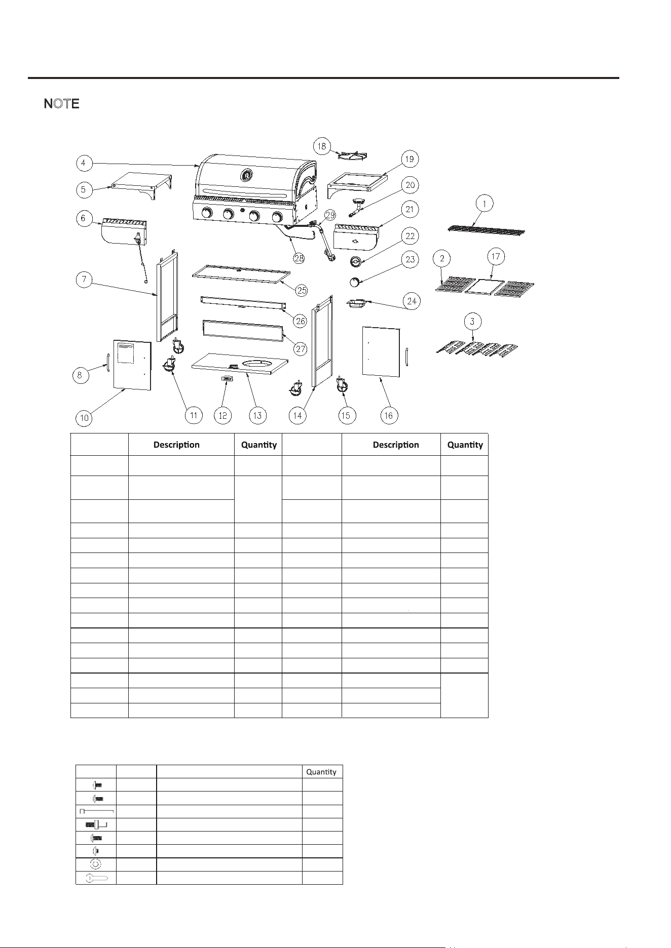
PACKAGE CONTENTS
NOTE: Please read the picture and product list of the package contents carefully before assembly.
Scan the QR code on the cover to watch the installation video.
Picture
Part No.
Part Descrip�on
36
4
2
2
1
4
4
1
AA
BB
CC
DD
EE
FF
GG
HH
M6x12mm
M4x10mm
M4x5mm
M4x10mm
M4
3
1 Insulated rack
1
17 Comal
2 Cooking grill 18 Burner rack
1
3 Fire spreader 19 Right burner table
1
4
Grill body assembly 1 20 Side burner 1
5
Left table 1 21 Right front panel 1
6
Left front panel 1 22 Knob base 1
7 Left frame 1 23 Knob 1
8 Door handle 2 24 Oil receiver box 1
9 / / 25 Oil receiver tray 1
10 Left door 1 26 Beam 1
11 Caster with brake 2 27 Backboard 1
12 Magnet base 1 28 Ignition needle 1
13 Baseboard 1 29 Gas hose assembly 1
14 Right frame 1 30 Left corner protector
15 Caster without brake 2 3
1 Right corner protector
16 Right door 1 32 Strengthening lath
The actual
parts may differ
depending on
the different
model.
Please refer to
the illustration
of the grill body
on page 10.
The actual parts may
differ depending on
the different model.
NOTE: Parts 25, 28, 29, 30, 31, 32 are preinstalled on the part 4.
NOTE:
Part Number Part Number
Warming rack
Cooking grate
Grill heat plate
Magnet
Cooking plate
Oil drip box
Oil drip tray
Back panel
Igniter
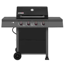
NOTE: The actual parts may differ depending on the different model. The model JD-3A contains 3 cooking grates of ordinary material and 3 grill heat plates, while
the model JD-4A contains 2 cooking grates of cast iron material, 1 cooking plate of cast iron material and 4 grill heat plates.
Warming rack
Cooking grate
Grill heat plate
Le� side table
Magnet
Bo�om panel
Cooking plate
Oil drip box
Oil drip tray
Back panel
Igniter
NOTE: The actual parts may differ depending on the different model. The model JD-3A contains 3 cooking grates of ordinary material and 3 grill heat plates, while
the model JD-4A contains 2 cooking grates of cast iron material, 1 cooking plate of cast iron material and 4 grill heat plates.
ASSEMBLY INSTRUCTIONS
4
CAUTION
THIS UNIT IS HEAVY. Two people are required for safe assembly.
Two people
required for safe assembly. Some parts may contain sharp edges. Wear
protective gloves if necessary. Read and follow all safety statements, warnings, assembly
instructions and use and care instructions before attempting to assemble and use.
ASSEMBLY INSTRUCTIONS
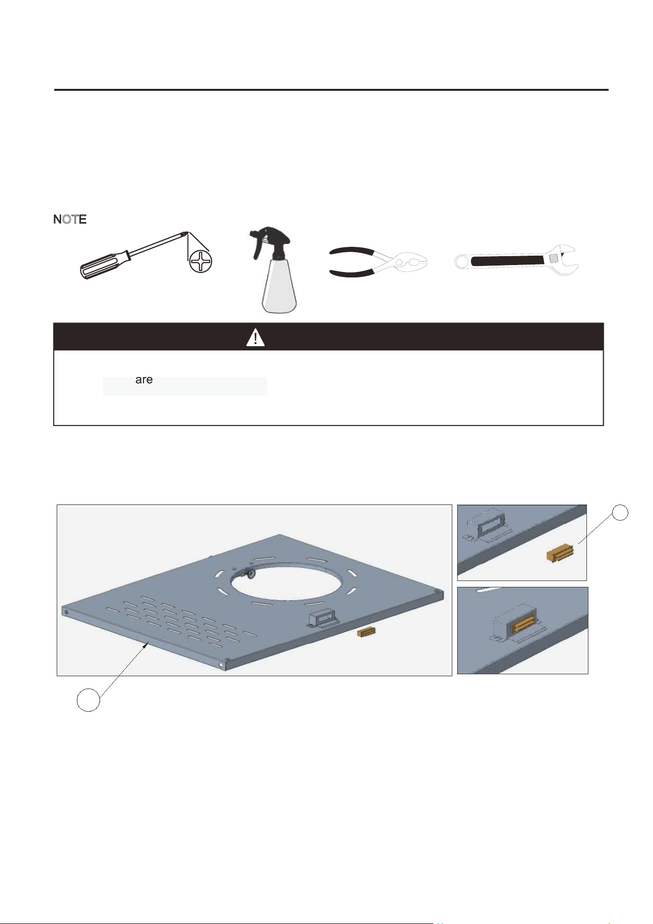
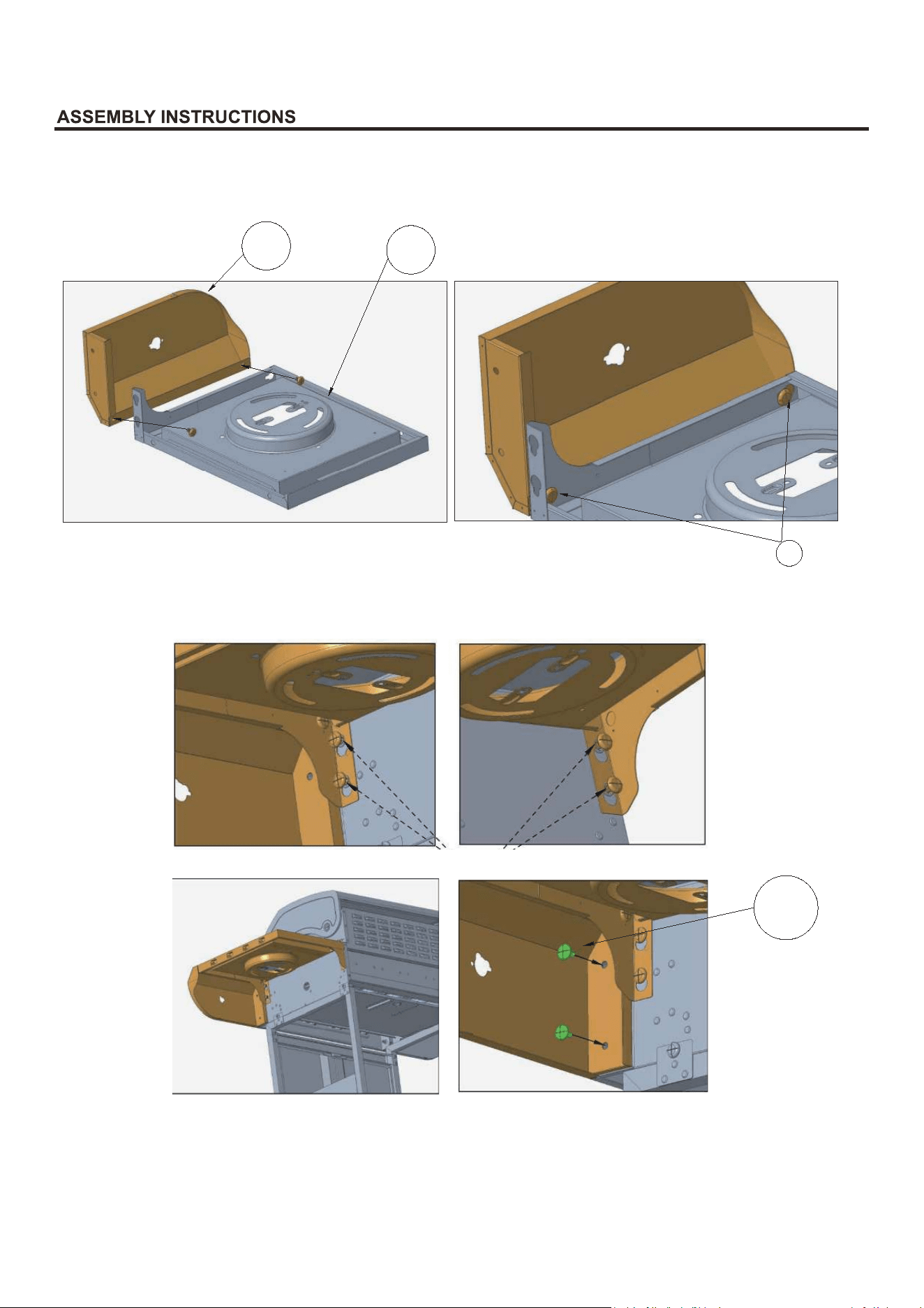
A.Installation of Magnet
Before start assembling product, make sure all parts are present. Compare parts and hardwares
with the list on the package contents page. If any part is missing or damaged, do not attempt to
assemble the product. Contact customer service for replacement parts.
Estimated Assembly Time: 50 minutes with 2 people.
Tools Required for Assembly and Leak Testing: Phillips screwdriver, Spray bottle, Pliers,
Adjustable Wrench
NOTE: Common tools used for assembly and leak testing are not included in the accessories.
Place the bottom panel (13) in the direction as shown in the figure (front side forward), insert the
magnet(12) into the base.
Note: Ensure that the adsorption surface of the magnet faces forward to adsorb and fix the two
doors which will be installed later.
12
13
12
13
aaaaaaaaa
5
ASSEMBLY INSTRUCTIONS
B.Installation of Left/Right Frame
Note: There is a L/R sticker on the left/right frame (ensure that the right frame is assembled on the
side near the nesting hole of the baseboard).
Place the left frame (7) (with sticker L affixed) and right frame (14) (with sticker R affixed) in the direction
shown in pictures above. Align the holes on the side of the two frames and the holes on the side of the
baseboard, assemble the frames and the baseboard together with 4 AA screws.
7
13
AA
13
14
AA
Left Side
Right Side
Note: There is a L/R scker on the le/right frame(ensure that the right frame is assembled on
the side near the nesng hole of the boom panel).
Place the le frame (7) (with scker Laffixed) and right frame (14) (with scker R affixed) in the
direcon shown in pictures above.Align the holes on the side of the two frames and the holes
on the side of the boom panel, assemble the frames and the boom panel together with 4AA
screws.
Note: There is a L/R s�cker on the le�/right frame(ensure that the right frame is assembled on
the side near the nes�ng hole of the bo�om panel).
Place the le� frame (7) (with s�cker L affixed) and right frame (14) (with s�cker R affixed) in the
direc�on shown in pictures above. Align the holes on the side of the two frames and the holes
on the side of the bo�om panel, assemble the frames and the bo�om panel together with 4 AA
screws.
Install the casters with brake (11) and the casters without brake (15) under the bottom of the
baseboard and adjust the height of the casters with the HH wrench.
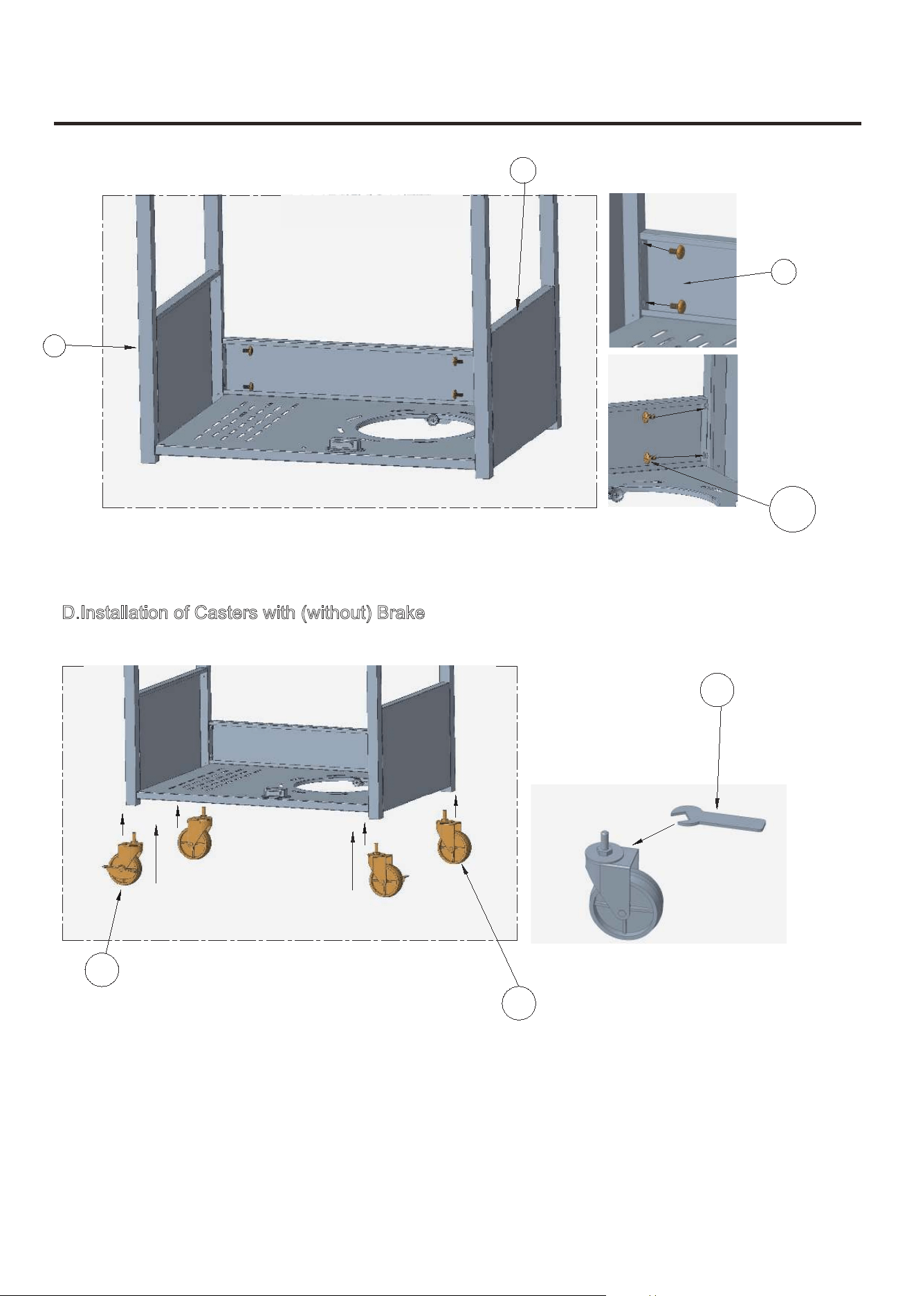
ASSEMBLY INSTRUCTIONS
C.Installation of Backboard
6
Install the backboard (27) between the left and right frames with 4 AA screws.
D
.Installation of Casters with (without) Brake
14
7
L
R
27
11
15
HH
NOTE: The casters can be locked and loosened by turning the brake.
NOTE: For easy movement, be sure to install the same type of casters on the same side of the base-
board.
AA
Back Panel
Install the back panel (27) between the le and right frames with 4AA screws
Install the casters with brake (11) and the casters without brake (15) under the boom of the
boom panel and adjust the height of the casters with the HH wrench.
NoTE:The casters can be locked and loosened by turning the brake.
NoTE:For easy movement,be sure to install the same type of casters on the same side of the boom
panel
Back Panel
Install the back panel (27) between the le� and right frames with 4 AA screws
Install the casters with brake (11) and the casters without brake (15) under the bo�om of the
bo�om panel and adjust the height of the casters with the HH wrench.
NOTE: The casters can be locked and loosened by turning the brake.
NOTE: For easy movement, be sure to install the same type of casters on the same side of the bo�om
panel.
7
ASSEMBLY INSTRUCTIONS
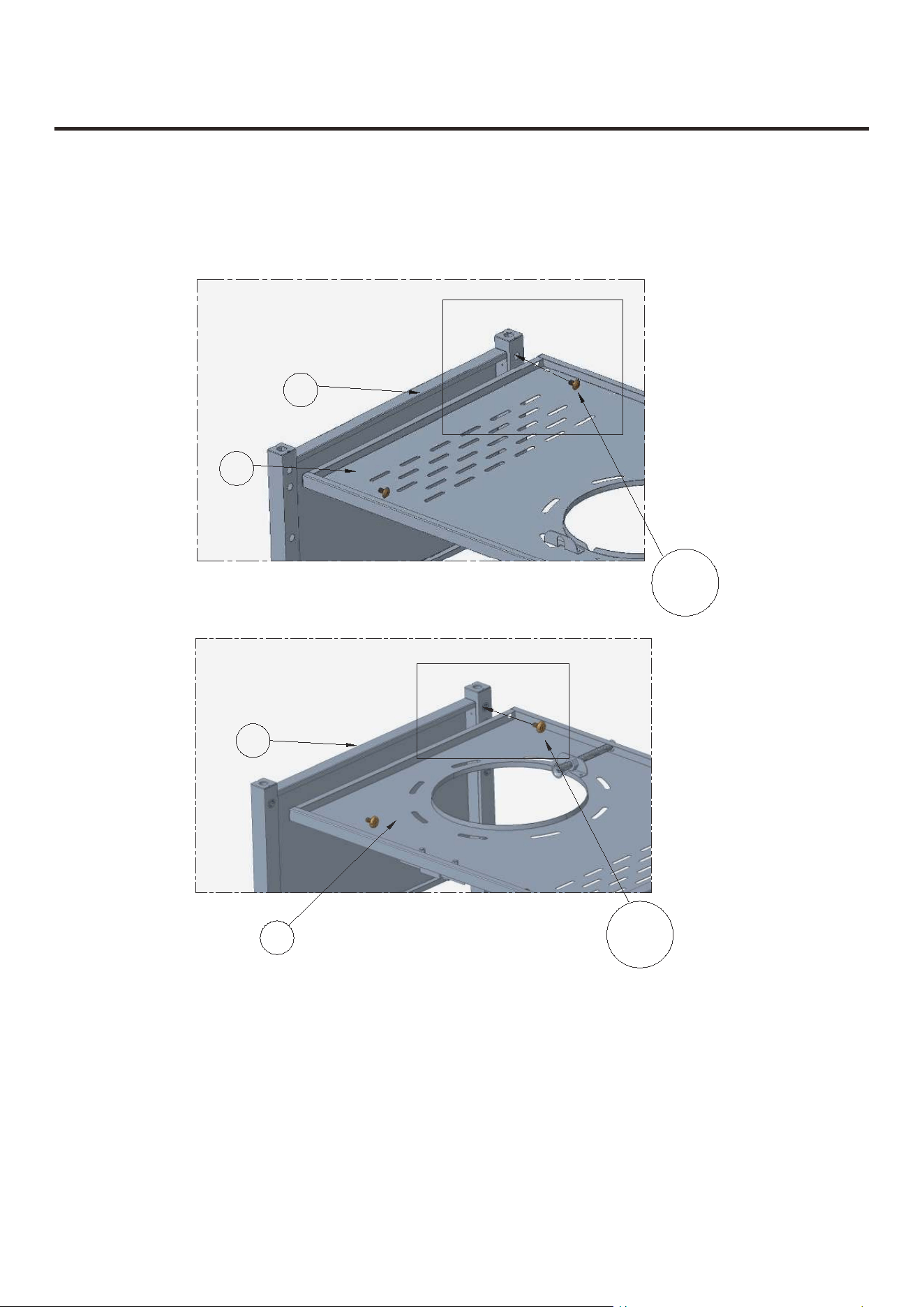
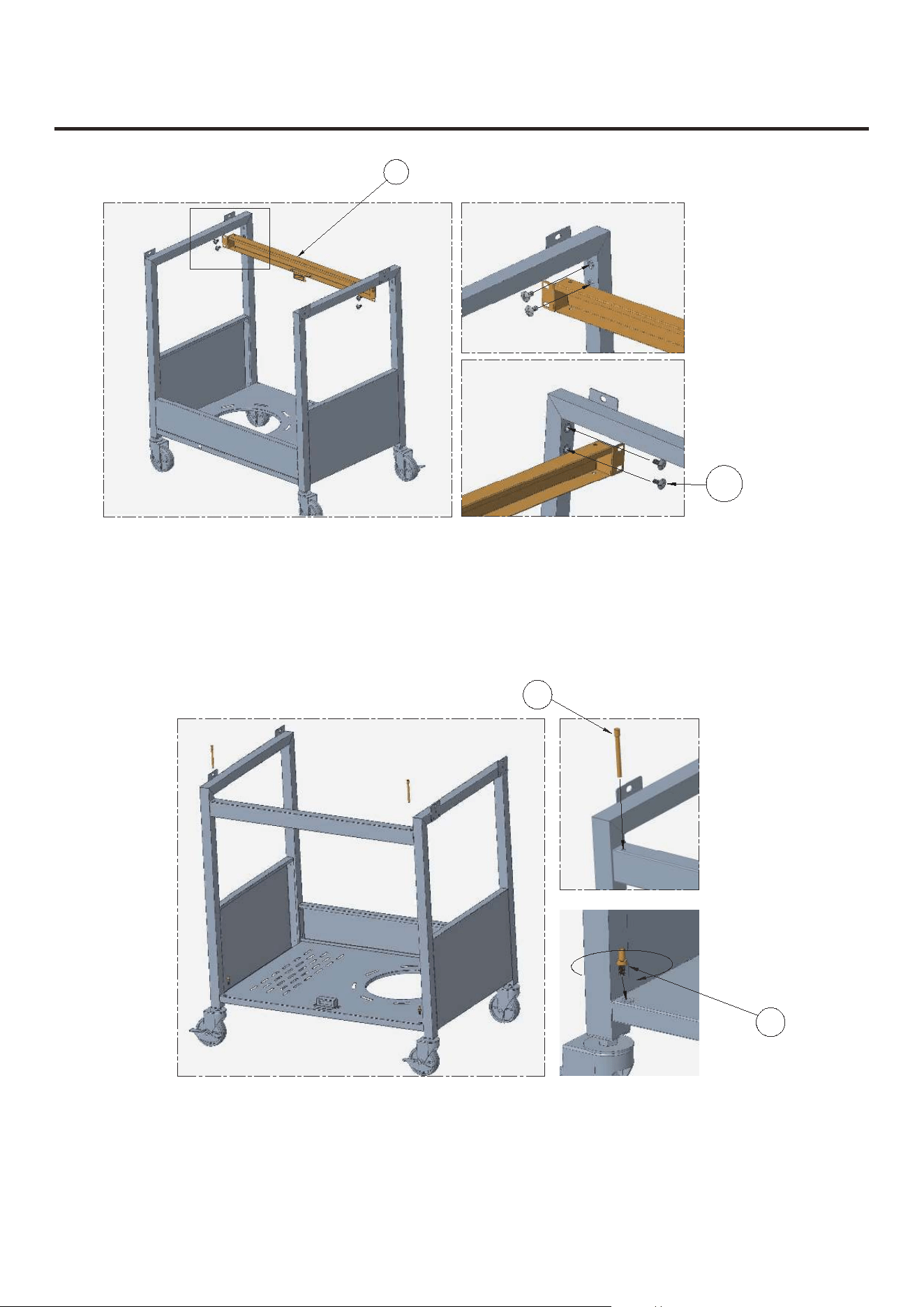
E.Installation of Beam
Place the baseboard in the direction shown in Picture (back side forward), and install the beam
(26) between the two frames with 4 AA screws.
N
ote: Ensure that the adsorption surface of the magnet base faces forward the front side to
adsorb and fix the two doors which will be installed later.
F.Pre-installation of CC and DD Screws
Place the baseboard in the direction shown in Picture (front side forward). Put 2 CC screws in
the corresponding positions on the beam, and put 2 DD screws in the corresponding positions
on the baseboard and tighten the DD screws for use when installing doors later.
26
AA
CC
DD
Back Side
Front Side
Place the unit in the direcon shown in Picture (back side forward),and install the beam
(26) between the two frames with 4 AA screws.
Note:Ensure that the adsorpon surface of the magnet unit faces forward the front side to
adsorb and fix the two doors which will be installed later.
Place the unit in the direcon shown in Picturefront side forward).Put 2 CC screws in
the corresponding posions on the beam,and put 2 DD screws in the correspondingposions
on the boom panel and ghten the DD screws for use when installing doors later.
Place the unit in the direc�on shown in Picture (back side forward), and install the beam
(26) between the two frames with 4 AA screws.
Note: Ensure that the adsorp�on surface of the magnet faces forward the front side to
adsorb and fix the two doors which will be installed later.
Place the unit in the direc�on shown in Picture front side forward) .Put 2 CC screws in
the corresponding posi�ons on the beam, and put 2 DD screws in the correspondingposi�ons
on the bo�om panel and �ghten the DD screws for use when installing doors later.
ASSEMBLY INSTRUCTIONS
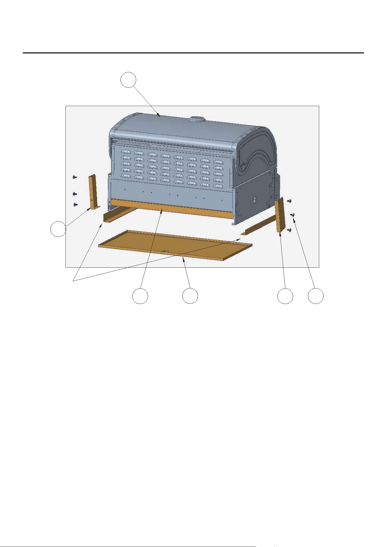
G.Remove the Protective Accessories from the Grill Body
8
25
32
30
31
4
AA
The grill body assembly (4) is a preinstalled part, among which (30), (31) and (32) are protective
accessories. These protective accessories and the protective packing paperboard of the oil drip
tray (25) should be taken out before installation as follows:
Step 1: Take out the left corner protector (30) and right corner protector (31), move the strengthening
lath (32) up along the grill body.
Step 2: Take out the oil receiver tray and then the strengthening lath.
Step 3: Remove the protective packing paperboard on both sides of the oil receiver tray, and then put
the oil receiver tray back.
NOTE: The removed screws of the corner protectors may be needed in the following step.
Protective packing paperboard
Back Side
Step 1:
lath (32) up along the grill body.
Step 2: Take out the oil drip tray and then the strengthening lath.
Step 3: Remove the protecve packing paperboard on both sides of the oil receiver tray, and then put
the oil drip tray back.
Step 1: Take out the le� corner protector (30) and right corner protector (31), move the strengthening
lath (32) up along the grill body.
Step 2: Take out the oil drip tray and then the strengthening lath.
Step 3: Remove the protec�ve packing paperboard on both sides of the oil drip tray, and then put
the oil drip tray back.
9
ASSEMBLY INSTRUCTIONS
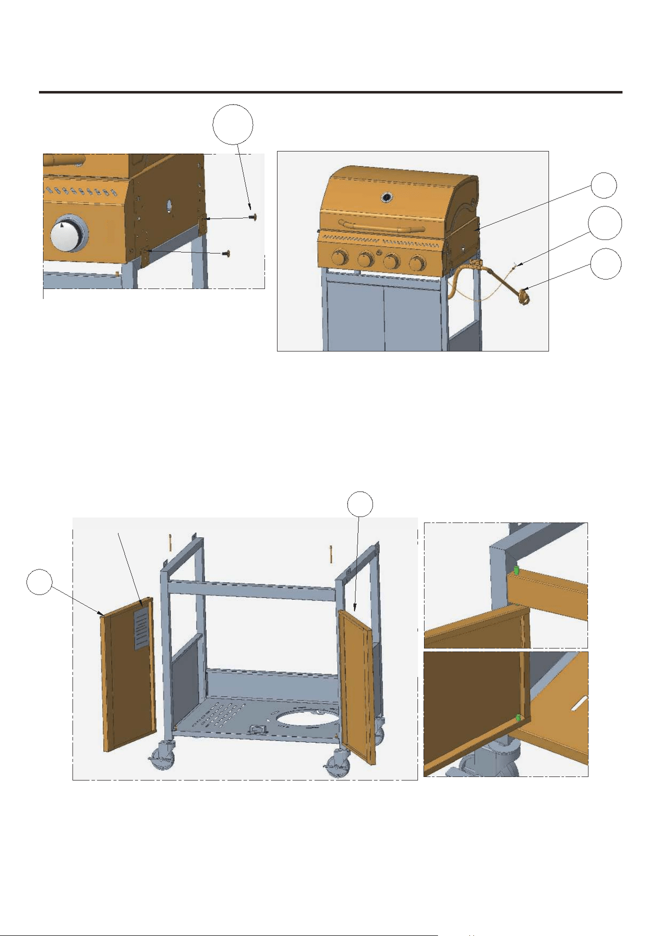
H.Installation of Grill Body
I.Installation of Left/Right Door
Install the grill body on the two frames with 4 AA screws.
Note: Before installing the grill body, it is necessary to pass the ignition needle (28) and the gas
hose assembly (29) through the right frame.
Insert the previously fixed DD screws into the holes at the bottom of the left door (10) and the right
door (16), and then adjust the CC screws into the holes at the top of the doors. You can adjust the
height of the casters with the HH wrench if the two doors don't line up.
4
28
29
10
AA
Note: There is a nameplate attached to the left door.
16
NOTE: Please note that both sides of the
grill body must be screwed with AA screws.
Note:Before installing the grill body,it is necessary to pass the igniter(28)and the gas
hose assembly (29) through the right frame.
Note: Before installing the grill body, it is necessary to pass the igniter (28) and the gas
hose assembly (29) through the right frame.
10
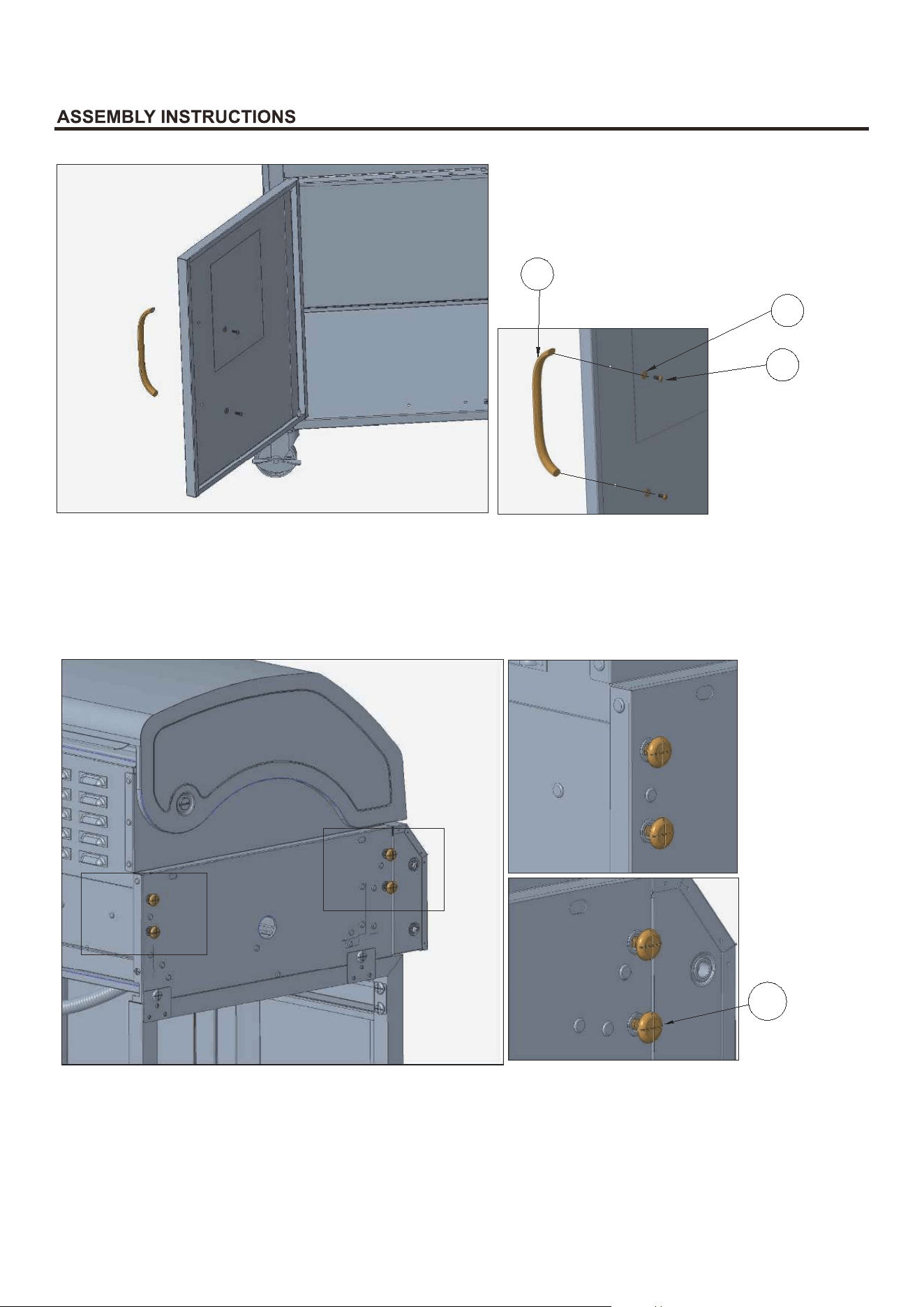
J.Pre-installation of Screws on the Grill Body
Preattach 8 AA screws respectively to the left and right sides of the grill body.
Note:Do not tighten the screws for following installation of the left table and the right burner table.
Install the door handles (8) to the doors with 4 GG spacers and 4 FF screws.
8
FF
GG
AA
Preaach 8 AAscrews respecvely to the le and right sides of the grillbody.
Note:Do not ghten the screws for following installaon of the le side table and theright burner
table.
Prea�ach 8 AA screws respec�vely to the le� and right sides of the grillbody.
Note: Do not �ghten the screws for following installa�on of the le� side table and the right burner
table.
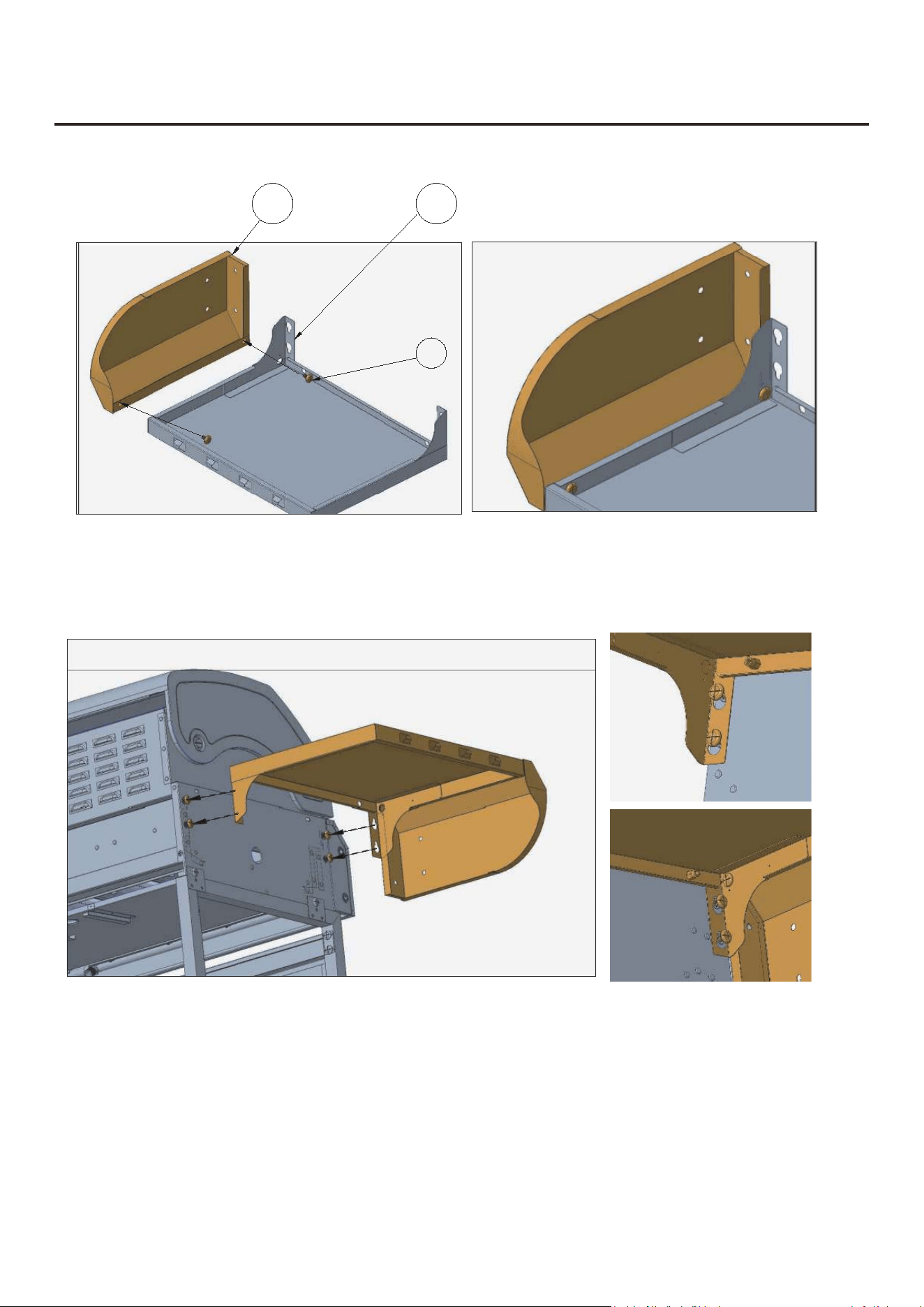
K.Installation of Left Table and Left Front Panel
Preattach 2 AA screws to the left front panel (6) (do not tighten), then assemble the left table (5)
and left front panel together and tighten the screws.
Align the left table with the 4 pre-attached AA screws on the left side of the grill body and then
tighten them.
ASSEMBLY INSTRUCTIONS
11
6
5
AA
Left Side
K.lnstallaonof Le Side Tableand LeFrontPanel
Preaach 2AA screws to the le front panel(6)(donot ghten),then assemble the le side table
(5) and le ront panel together and ghten the screws.
Align the le side table with the 4pre-aached AA screws on the le side of the grill body and then
ghten them.
K.lnstalla�onof Le� Side Table and Le� Front Panel
Pre-a�ach 2 AA screws to the le� front panel (6) (donot �ghten), then assemble the le� side table
(5) and le� front panel together and �ghten the screws.
Align the le� side table with the 4 pre-a�ached AA screws on the le� side of the grill body and then
�ghten them.
12
Fix the left front panel to the left side of the grill body with 2 AA screws.
Fix the left table to the left side of the grill body with 2 AA screws screwing from inside the grill body.After
adjustment, tighten the 4 pre-attached AA screws on the left side of the grill body to completely fix the left
table and the left front panel together with the grill body.
AA
AA
Fix the le side table to the le side of the grill body with 2 AA screws screwing from inside the grill body.Aer
adjustment,ghten the 4 pre-aached AA screws on the le side of the grill body to completely fix the le
side table and the le front panel together with the grill body.
Fix the le� side table to the le� side of the grill body with 2 AA screws screwing from inside the grill body. A�er
adjustment, �ghten the 4 pre-a�ached AA screws on the le� side of the grill body to completely fix the le�
side table and the le� front panel together with the grill body.
13
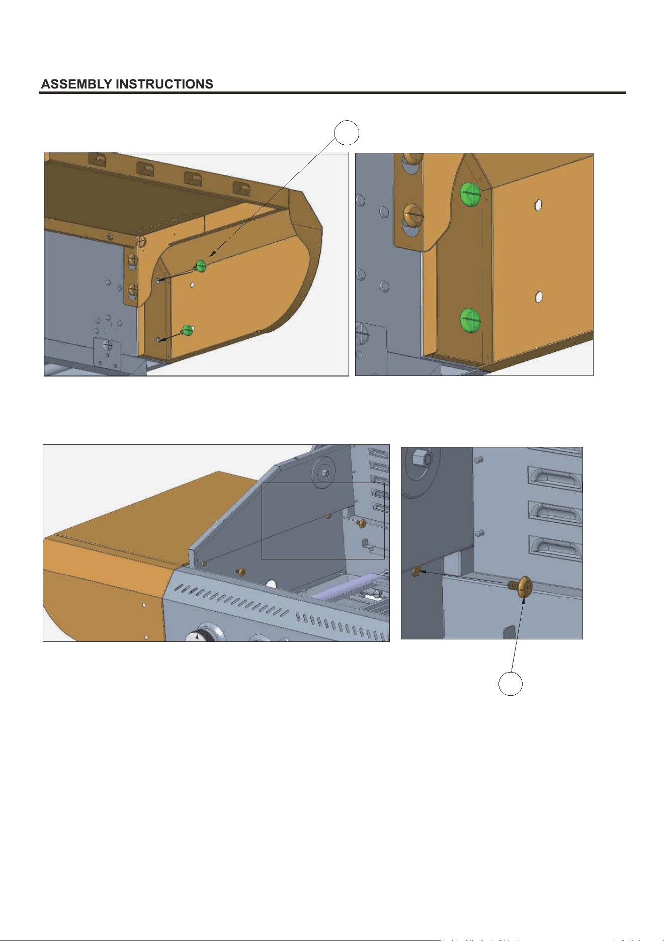
L.Installation of Right Burner Table and Right Front Panel
Align the right burner table with the 4 pre-attached AA screws on the right side of the grill
body and then tighten them.
Fix the right front panel to the right side of the grill body with 2 AA screws.
Preattach 2 AA screws to the right front panel (21) (do not tighten), then assemble the right burner
table (19) and the right front panel together and tighten the screws.
21
19
AA
AA
Tighten the screws
Right Side
14
Fix the right burner table to the right side of the grill body with 2 AA screws screwing from inside the
grill body.
After adjustment, tighten the 4 pre-attached AA screws on the right side of the grill body to complete-
ly fix the right burner table and the right front panel together with the grill body.
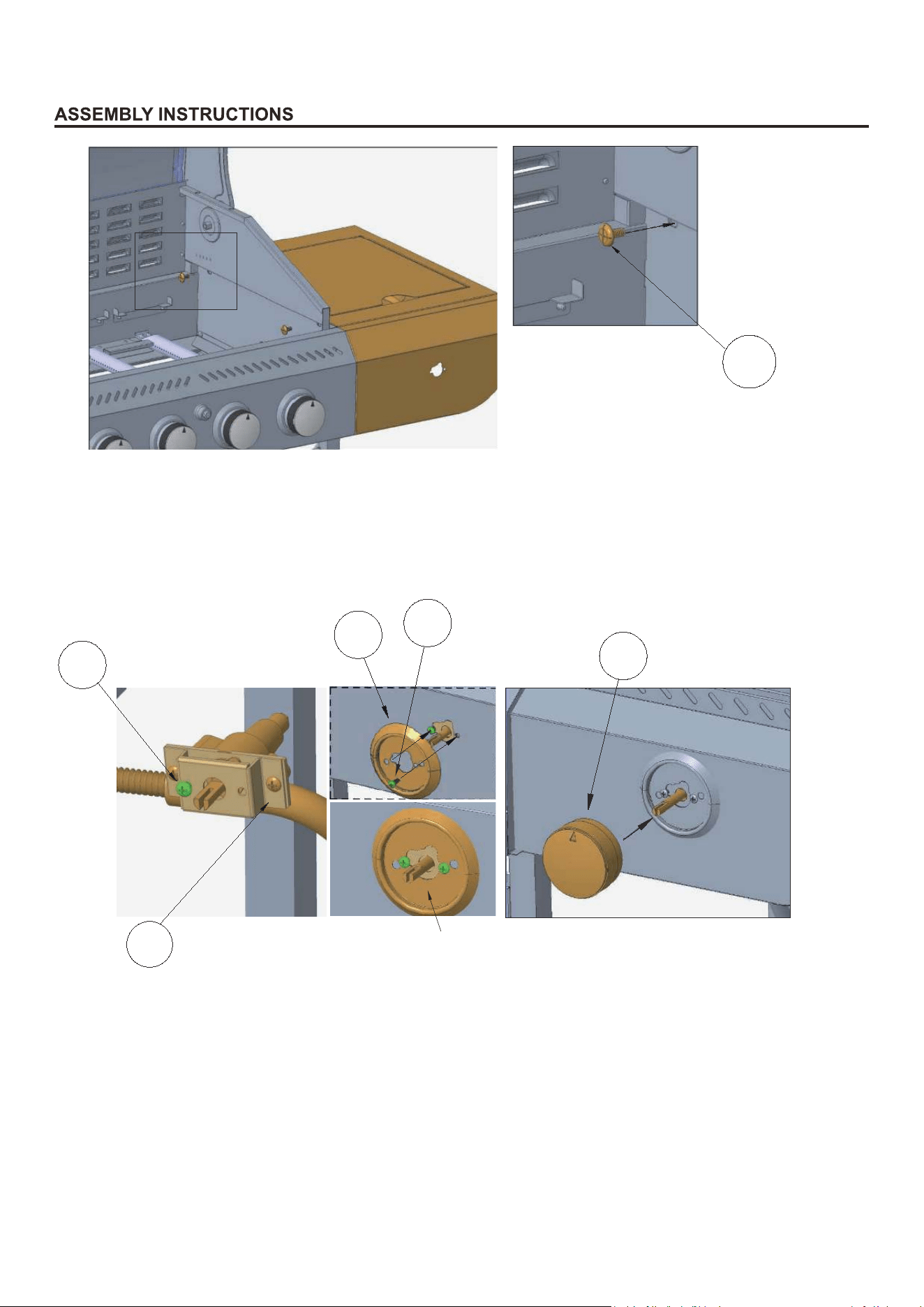
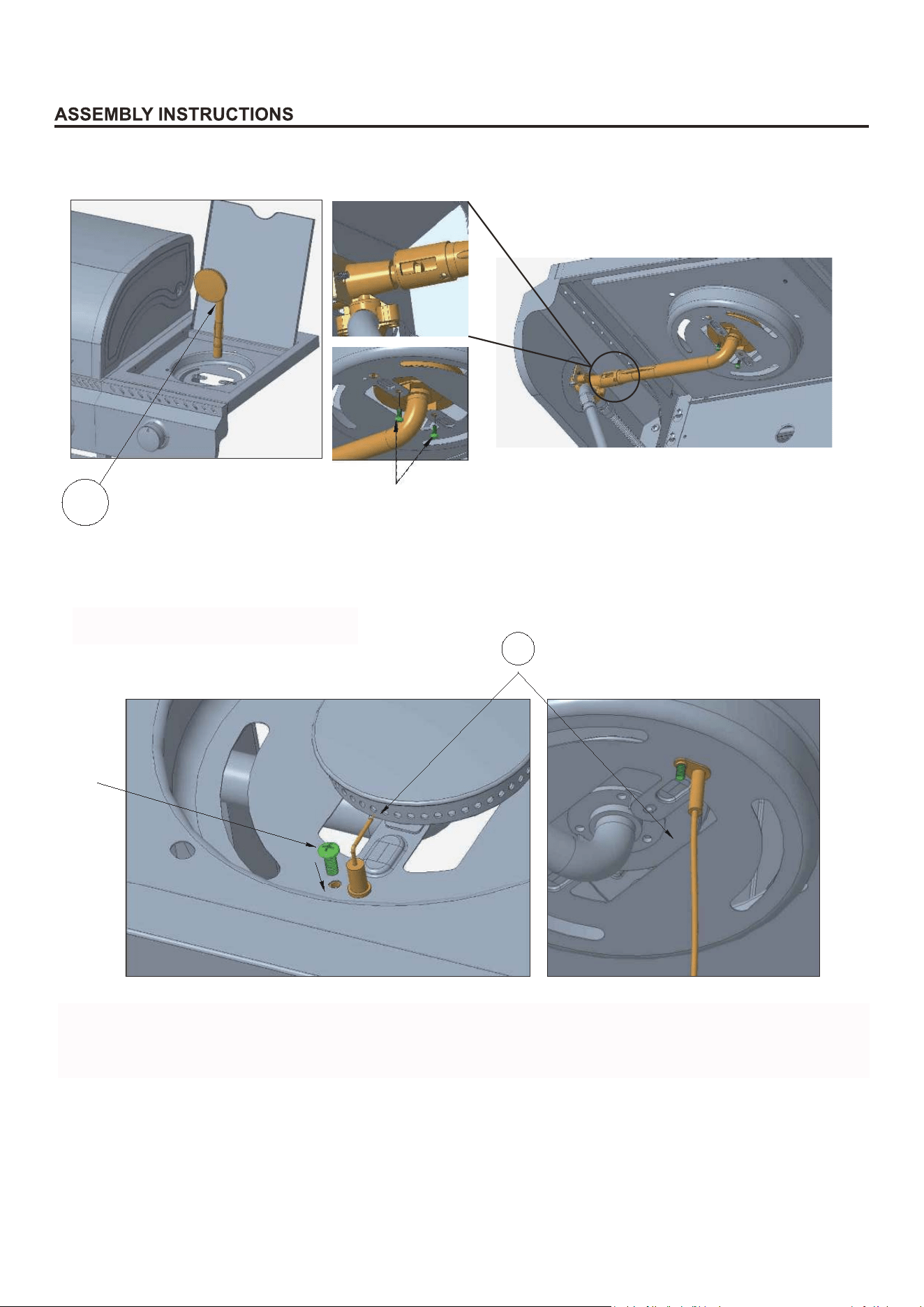
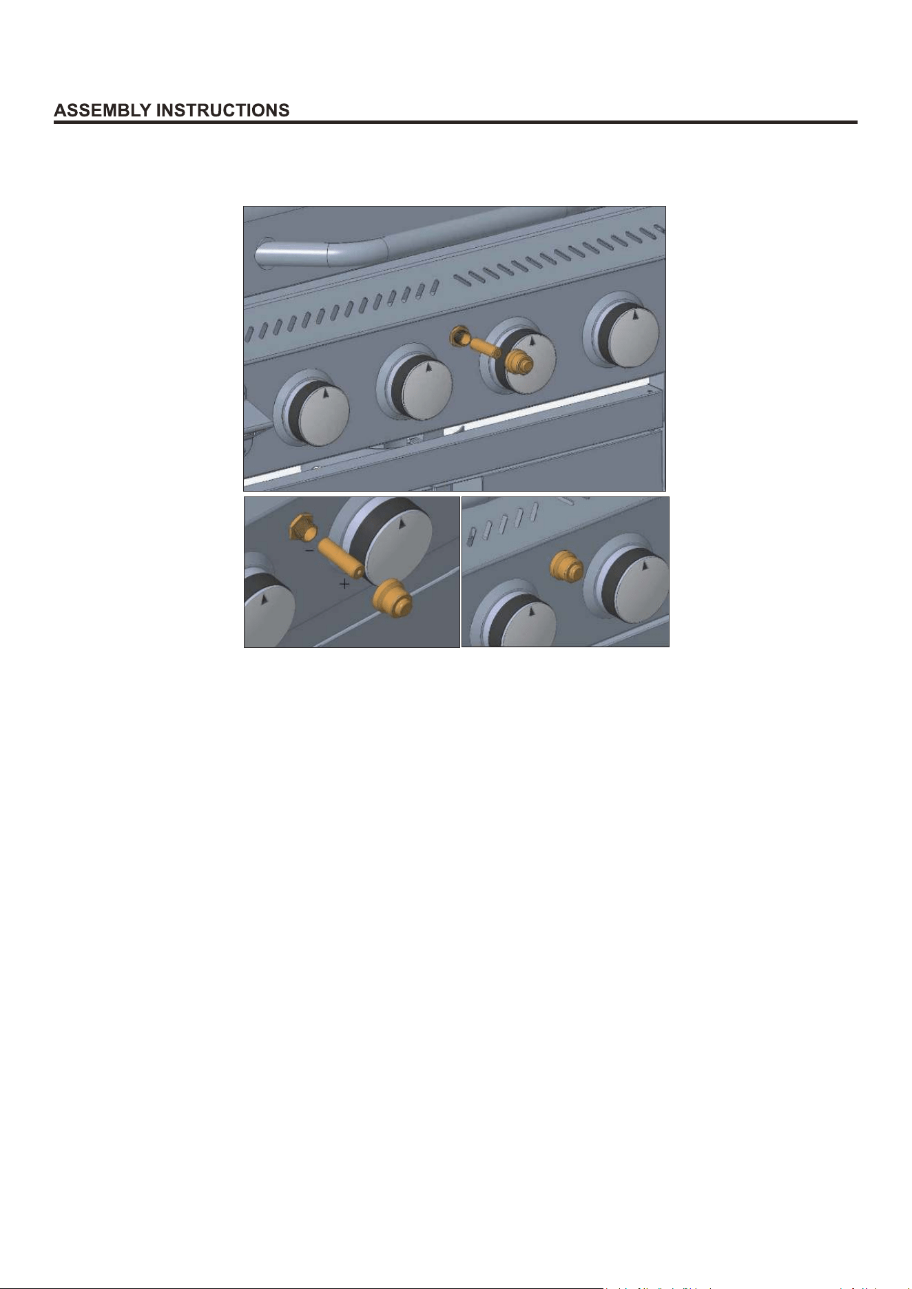
M.Installation of Knob and Valve
Step 1. Pre-attach a BB screw to the left hole (near the bellows side) on the valve of the hose
assembly (do not tighten).
Step 2. Align the knob base (22) with the big hole of the right front panel from the front, stick the
valve out from the back of the right front panel. Making sure that the pre-attached BB screw
is aligned with the small semicircular holes both on the left of the panel and the knob base.
Step 3. Pass a BB screw through the small round holes both on the right of the panel and the knob
base, and tighten the 2 BB screws to fix the valve and knob base together.
Step 4. Align the knob (23) with the valve and insert into the valve.
AA
29
22
23
BB
BB
The knob base and valve are fixed
15
N.Installation of Side Burner
Place the ignition needle through the round hole on the right burner table (as shown in the
picture) from the bottom up, adjust the direction and place a EE screw through the other
round hole to fix the ignition needle to the right burner table.
Insert the side burner (20) into the middle of the right burner table from the top down, put
the tail of the side burner over the valve , then fix the side burner to the right burner table
with 2 BB screws from below.
O.Installation of Ignition Needle
20
28
EE
BB
O.lnstallaon of Igniter
Place the ignion needle through the round hole on the right burner table(asshown in the
picture)from the boom up,adjust the direcon and place a EE screw through the other
round hole to fix the igniter to the right burner table.
O.lnstalla�on of Igniter
Place the ignitor through the round hole on the right burner table (as shown in the
picture) from the bo�om up, adjust the direc�on and place a EE screw through the other
round hole to fix the igniter to the right burner table.
16
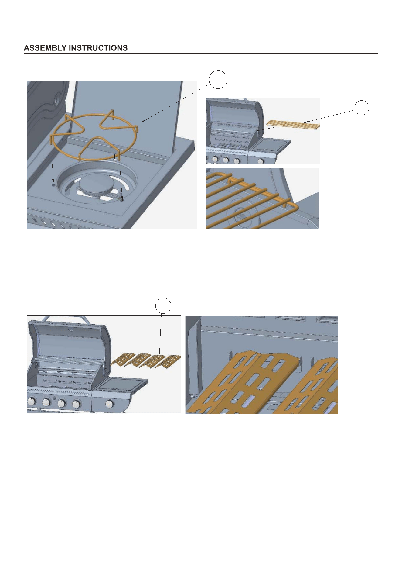
P.Installation of Insulated Rack and Burner Rack
Q.Installation of Fire Spreader
Insert the burner rack (18) into the specified holes on the right burner table. Then insert the
insulated rack (1) into the specified holes on both sides of the grill body.
Install the fire spreader (3) in place, noting that each fire spreader must be placed in the
specified slot.
18
1
3
P.lnstallaon of Warming Rack and Burner Rack
Q.lnstallaon of Grill Heat Plate
Insert the burner rack (18) in to the specified holesonthefightburnertable.Then insert the
Warming Rack (1) into the specified holes on both sides of the grill body.
Install the grill heat plate (3) in place,nong that each grill heat plate must be placed in the
specified slot.
P.lnstalla�on of Warming Rack and Burner Rack
Q.lnstalla�on of Grill Heat Plate
Insert the burner rack (18) into the specified holes on the right burner table. Then insert the
warming rack (1) into the specified holes on both sides of the grill body.
Install the grill heat plate (3) in place, no�ng that each grill heat plate must be placed in the
specified slot.
17
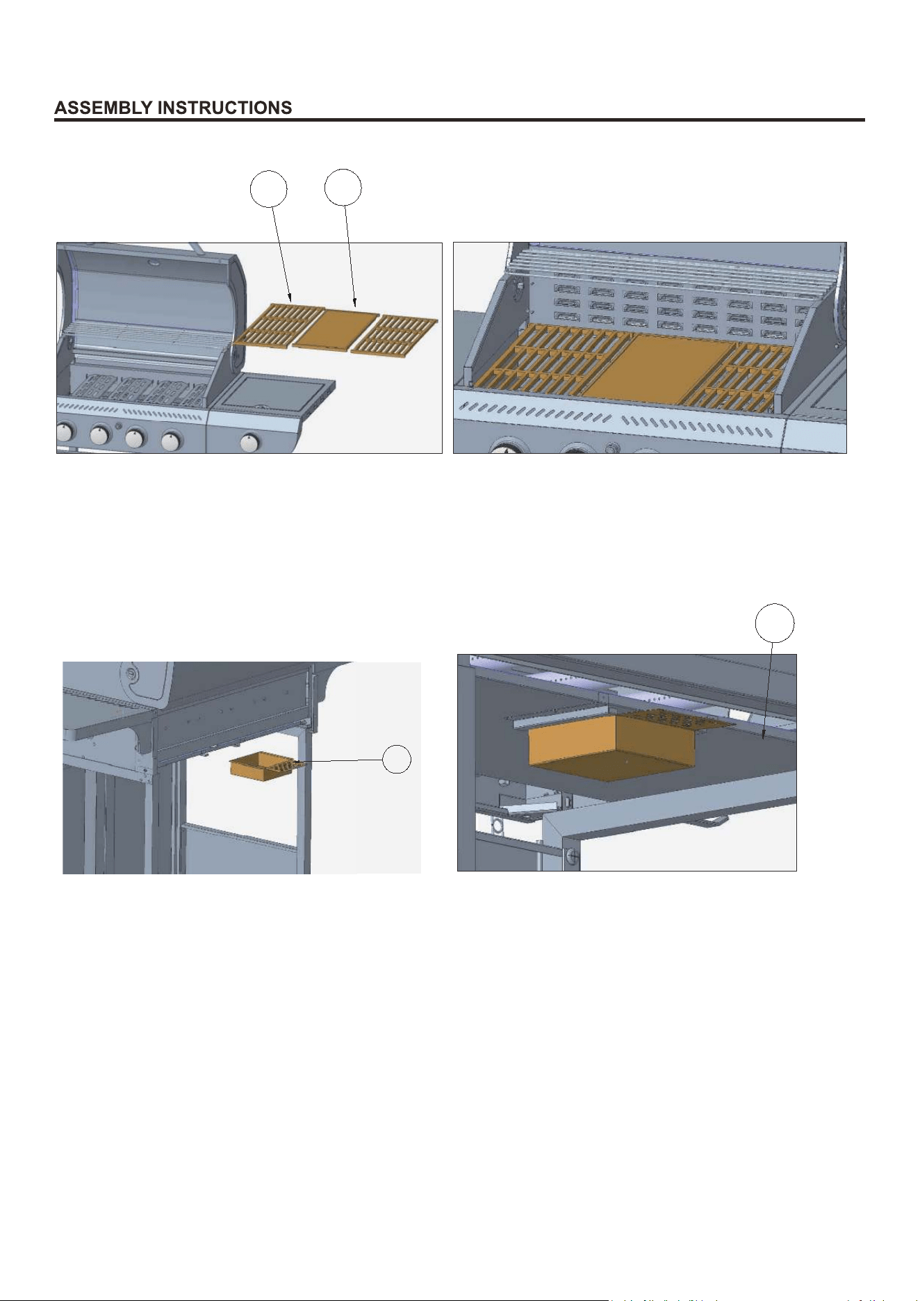
R.Installation of Cooking Grate and Plate
Install the cooking grills (2) and comal (17) on the specified step.
S.Installation of Oil Receiver Box
Insert the oil receiver box (24) along the guide rail of the oil receiver tray (25).
3
17
24
25
Back Side
S.lnstallaon of Oil Drip Box
Install the cooking plate (2)and plate(17) on the specified step.
Insert the oil drip box (24) along the guide rail of the oil drip tray(25)
S.lnstalla�on of Oil Drip Box
Install the cooking grates (2) and plate (17) on the specified step.
Insert the oil drip box (24) along the guide rail of the oil drip tray (25).
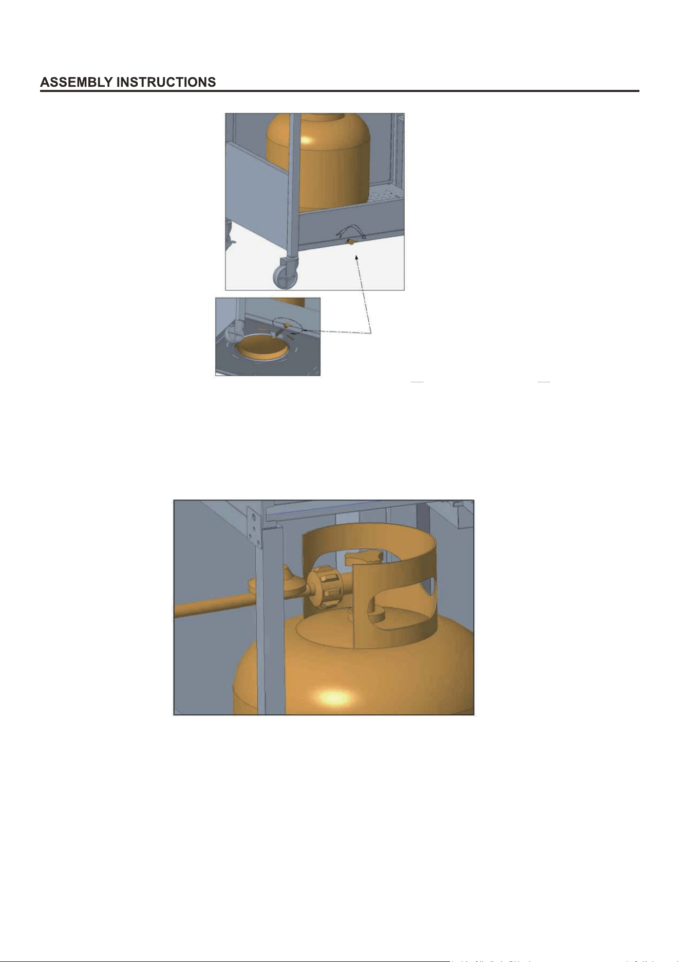
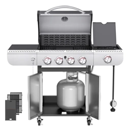
T.Secure Gas Tank
Open the two doors and place the gas tank into the nesting hole of the baseboard. Clockwise
tighten the butterfly screw on the back of the baseboard to secure the gas tank in place.
Connect and tighten the regulator valve of the gas hose assembly to the threaded valve of the
tank to ensure that there is no methane leakage.
18
U.Connect Gas Hose Assembly
Back Side
Back Side
Open the two doors and place the gas tank into the nesng hole of the boom panel.
Clockwise ghten the buerfly screw on the back of the boom panel to secure the
gas tank in place.
Open the two doors and place the gas tank into the nes�ng hole of the bo�om panel.
Clockwise �ghten the bu�erfly screw on the back of the bo�om panel to secure the
gas tank in place.
19
V.Installation of Battery
Screw the ignition button out, then insert the battery into the hole and screw the ignition button in.
Note: The "+" pole faces outward and the "-" pole faces inward.
Note: To ignite the burners, hold down and turn the gas control knob anticlockwise first to
ensure that the gas in the tank is released, then press the ignition button for 3 to 4 seconds.
20
OPERATION INSTRUCTIONS
CHECKING FOR LEAKS
gs on the
threaded valve of the LP gas
tank, gas hose and regulator valve for leaks with a water and soap solution.
• Always perform leak test prior to lighting the grill.
• Do not smoke while testing for a leak.
• Always perform leak tests outdoors in a well-ventilated area.
• Prepare leak test solution by 50/50 ratio of liquid dish soap and water.
Total solution required is approximately 2 - 3 ounces (70 - 90 ml).
Put leak test solution in a spray bottle
• Do not use the grill until any and all leaks are corrected.
• If you are unable to correct a leak, disconnect the propane supply and call a gas appliance service
dealer.
PERFORM LEAK TEST
.
• Ensure all control knobs are in the "O" (OFF) position.
• Connect the gas hose to the gas supply.
• Spray leak test solution on all
• Open the threaded valve of the LP gas tank.
gas-carrying connections an
of applied test solution indicates a gas leak. If leaks are detected
or you smell or hear gas, shut off the
gas supply valve immediately and repair or replace the defective part. Do not use the grill until
all leaks are corrected.
WARNING
ALL INSTRUCTIONS AND SAFEGUARDS ON THIS PAGE MUST BE FOLLOWED TO
PREVENT FIRE, DAMAGE AND/OR INJURY.
CAUTION
Only use the regulator valve and hose assembly provided!
If a replacement is necessary,
please
call
our customer service center. Do not use replacement parts that are not intended for this grill.
1
the regulator valve when the grill is not in use.
The propane gas supply cylinder to be used must be constructed and marked in accordance with the
Standard of Canada, CAN/CSA-B339, Cylinders, Spheres and Tubes for Transportation of Dangerous
Goods; and Commission, as applicable; and provided with a liste
Use only 20-pound cylinders (height: 18.11 inches, tank diameter: 9.84 inches, foot diameter: 8.03
inches) equipped with a cylinder connection device compatible with the connection for outdoor
cooking appliances.
The cylinder must include a collar to protect the cylinder valve. The gas cylinder should not be dropped
or handled roughly!
If the appliance is not in use, the gas cylinder must be disconnected. Storage of an appliance indoors
is permissible ONLY if the cylinder is disconnected and removed from the appliance. Cylinders must
be stored outdoors out of the reach of children and can not be stored in a building, garage or any
other enclosed area. Your cylinder must never be stored where temperatures can reach over 125°F.
Place the dust cap on the cylinder valve outlet whenever the cylinder is not in use. Only install the
type of dust cap on the cylinder valve outlet that is provided with the cylinder valve. Other
types of caps or plugs may result in leakage of propane.
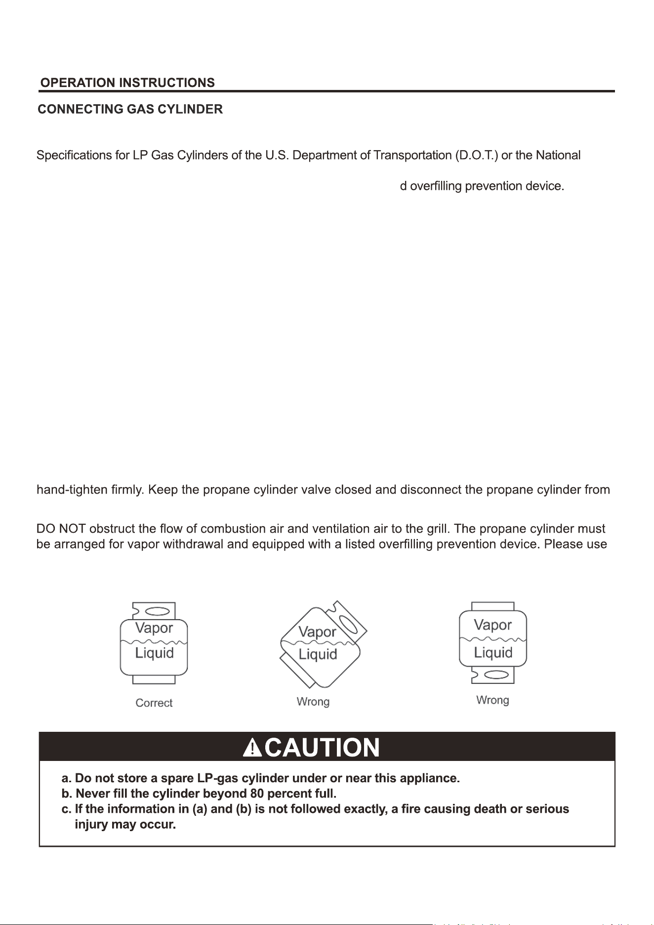
Before connection, be sure that there is no debris caught in the outlet of the gas cylinder, outlet of the
regulator valve or in the outlet of the burner and burner ports. Connect regulator valve and
the proper cylinder orientation to provide vapor withdrawal. NOTE: The cylinder must be fully upright
for the cylinder to have vapor withdrawal only.
21
22
OPERATION INSTRUCTIONS
WARNING
ALL INSTRUCTIONS AND SAFEGUARDS ON THIS PAGE MUST BE FOLLOWED TO
PREVENT FIRE, DAMAGE AND/OR INJURY.
WARNING
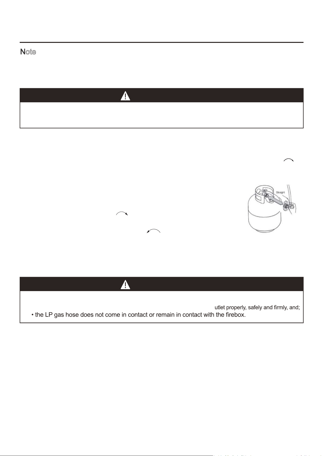
In the connection process, make sure:
• the regulator valve
inlet connector mates with the cylinder valve o
CONNECTING THE LP TANK
1
.
The
threaded valve
on the LP tank must be closed. Make sure that the
threaded valve
is turned
threaded valve outlet. Be sure the nipple is centered in the valve outlet.
Use carefully – do not cross-thread the connection.
5.
Hand-tighten the regulator valve
clockwise until it comes to a full
stop. Firmly tighten it by hand only. Do not use tools.
To Disconnect:
Turn the
regulator valve
Note: Other cylinders may be acceptable with this appliance if they are compatible
with the nesting hole and retention means of the appliance. Refer to Step Q of
clockwise
to a
full stop. The cylinder supply system must be arranged for vapor withdrawal.
2. Check that the control knob on the
grill body
is turned off.
3. Remove the protective cap from the LP tank valve and the regulator valve of the hose
.
4.
counterclockwise
until the regulator assembly detaches.
Hold the regulator valve in one hand and insert the nipple into the
Assembly Instructions for correcting the cylinder to the cylinder holder connection.
2
counterclockwi
4. Hold down and turn the gas control knob anticlockwise first to ensure that the gas in the tank is
released, then press the ignition button for 3 to 4 seconds. If ignition does not take place within 5
seconds, immediately turn the control knob to the "O" OFF position. Wait 5 minutes and repeat
step 4 above or refer to fire rod lighting instructions in the manual.
5. Repeat step 4 above to ignite all other burners. If the burner still does not light, check that there
is gas in the cylinder and follow the fire rod lighting instructions.
Check the Troubleshooting Guide for more information.
se.
3
OPERATION INSTRUCTIONS
Lighting The Grill
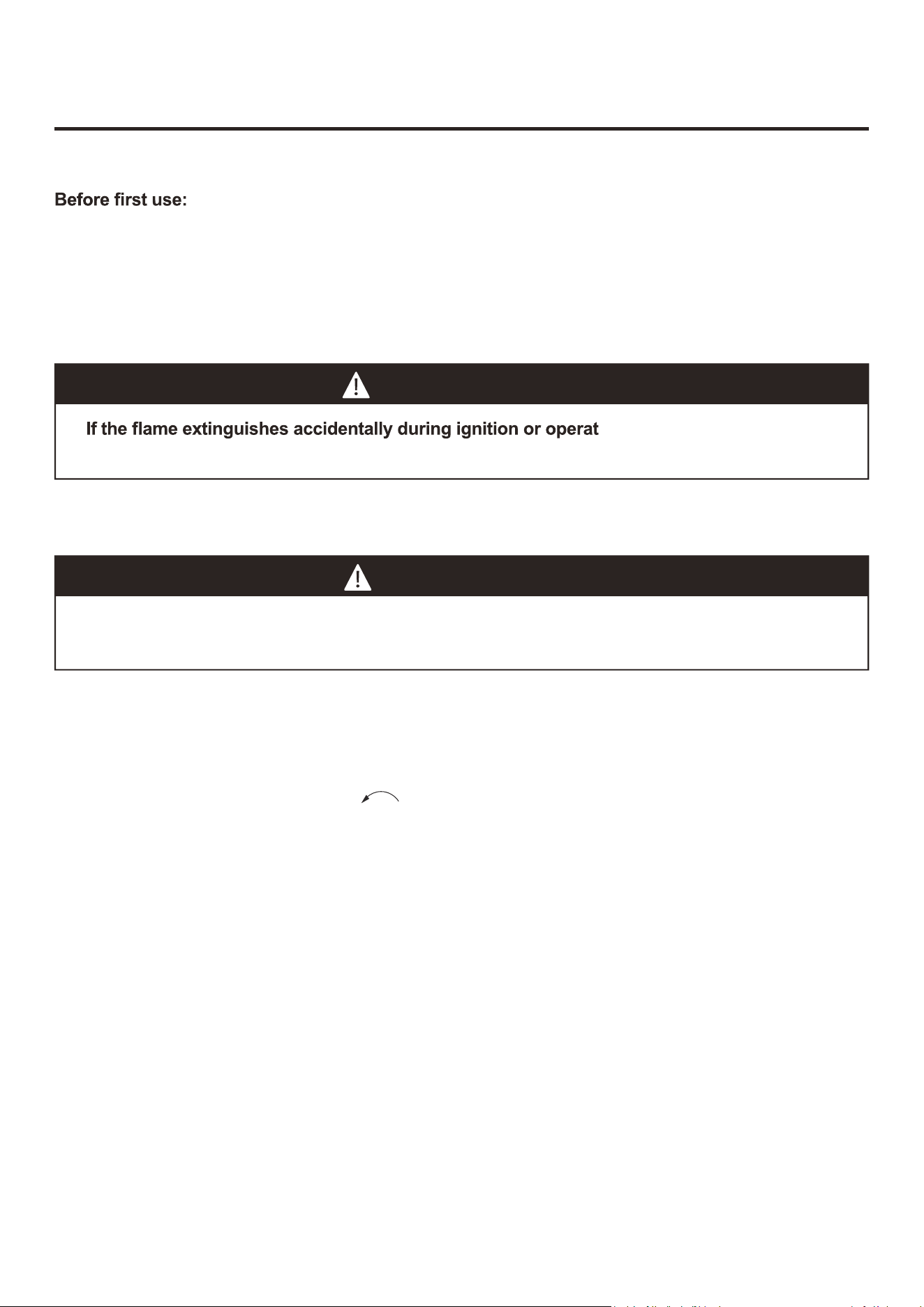
Remove all hangings or plastic straps, if present. Before you cook on your new gas grill, it is important
to clean your grill with heat. To do this, operate the grill for approximately 15 minutes with the lid closed
and the control knob in the highest position. This will clean the internal parts by burning off any residue
and odor from the manufacturing process.
WARNING
Do not lean over grill when lighting. Read instructions before lighting.
CAUTION
ion, immediately TURN OFF the
cylinder valve and then TURN OFF the control knob.
1. Check that the control knobs are at the "O" OFF position.
2. Open valve at tank fully by turning
3. Open the lid during lighting.
24
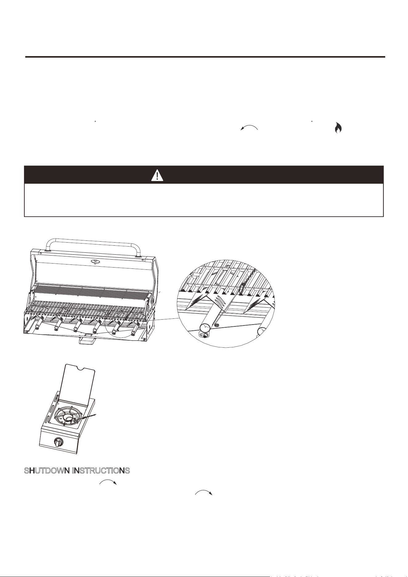
S
HUTDOWN INSTRUCTIONS
1. Turn control knobs
2. Close threaded valve of the tank fully by turning
3. Close
clockwise to the
“O”
OFF position.
the lid.
clockwise.
Turn off LP supply at the cylinder when the appliance is not in use.
CAUTION
Make sure all burners controls are off except for the burner being lit and the
burners that have been lit.
Fire Rod Lighting of Main Burner
Fire Rod Lighting of Side Burner
between the
fire spreaders
as shown. Make sure the lit
rod
is close to the burner ports
OPERATION INSTRUCTIONS
LIGHTING THE GRILL WITH
THE FIRE ROD
1. Open the lid.
2. Insert
the fire rod.
3. Light the fire rod.
4. Immediately place the lit
rod
through the spaces in the
cooking grills
near the ports of the burner
.
5. Press in the control knob that operates the burner and rotate
counter-clockwise to High
position and burner should light immediately.
6. Repeat 2–5 steps to light
the remaining burners.
7. Adjust burners to desired cooking settings.
4.Immediately place the lit rod through the spaces in the cooking grills near the ports of the burner
between the fire spreaders as shown.Make sure the lit rod is close to the burner ports.
4. Immediately place the lit rod through the spaces in the cooking grates near the ports of the burner
between the grill heat plates as shown. Make sure the lit rod is close to the burner ports.
25
CARE AND MAINTENANCE
Cooking
Grills and Comal
The best time to ‘burn-off’ the cooking
grills and comal
is after every use (approx. 15 minutes). They
already hot from cooking thus requiring less fuel to obtain necessary temperature for ‘burn-off’.
To "burn off" or heat clean them, turn the burners to highest position and run for 15 minutes
with the lid closed. Then turn off the burners and use a wire brush to clean excess food residue
from the grates.
The procelain grills have an enamel finish (similar to glass) and should be handled with
care not to chip.
CAUTION
Ensure the grill is cool before cleaning and conducting maintenance and with the gas supply
turned off at the LP-Gas Cylinder.
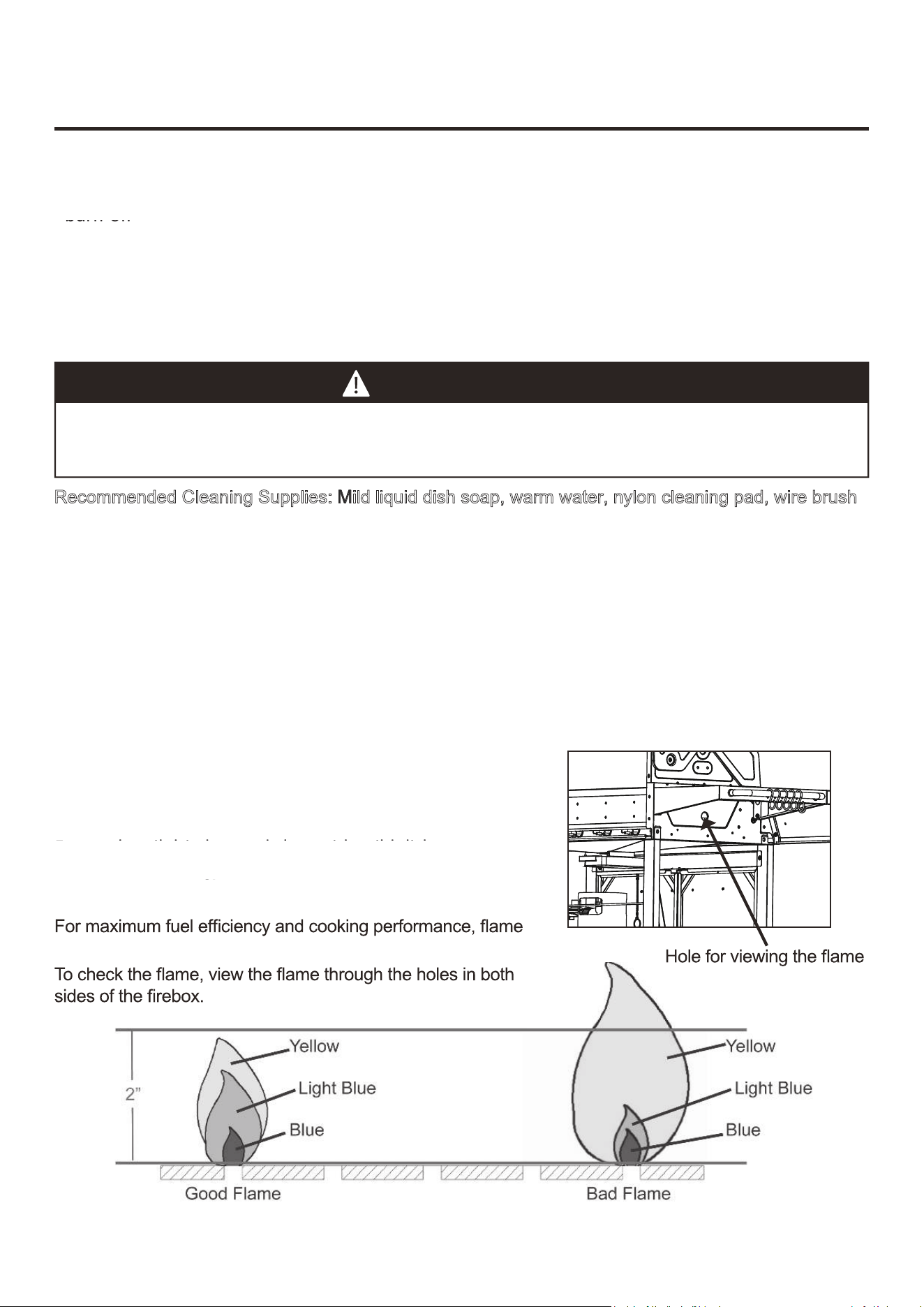
Recommended Cleaning Supplies: Mild liquid dish soap, warm water, nylon cleaning pad, wire brush
NOTE: DO NOT use cleaners that contain acid, mineral spirits or any abrasive substance.
Outside Surfaces
It is recommended to use only mild dish soap and hot water to clean grill and grill parts.
Rinse with warm water.
Inside Bottom Pan of Grill Body
To avoid flare-ups, the bottom pan of the grill body should be kept clean on a regular basis.
Remove residue using a brush, scraper and/or cleaning pad. Wash with mild dish soap and warm
water. Rinse with warm water. Avoid water splashing into venturi tubes of burners.
Fire Spreader
Clean residue with wire brush and wash with mild dish soap and
warm water. Rinse with warm water.
Oil Receiver Box
Empty the oil receiver box and clean with mild dish soap and
warm water on a regular basis.
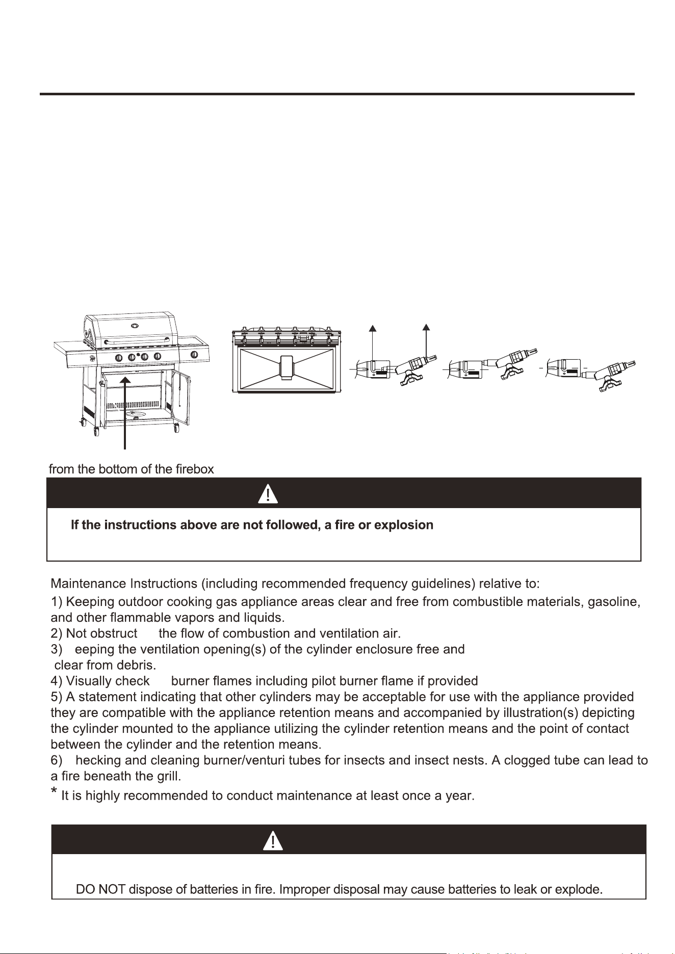
Checking The Flame
should be a blue-yellow color and be between 1-2 inches high.
Cooking Grates and Plate
Grill Heat Plate
Oil Drip Box
The best �me to “burn-off” the cooking grates and plate is a�er every use (approx. 15 minutes).
They are already hot from cooking thus requiring less fuel to obtain necessary temperature for
‘‘burn-off’’.
Empty the oil drip box and cleanwith mild dish soap and
warm wateron a regular basis.
Cooking Grates and Plate
Grill Heat Plate
Oil Drip Box
The best �me to “burn-off'' the cooking grates and plate is a�er every use (approx. 15 minutes).
They are already hot from cooking thus requiring less fuel to obtain necessary temperature for
‘‘burn-off’’.
Empty the oil drip box and clean with mild dish soap and
warm water on a regular basis.
26
CARE
Figure 2
AND MAINTENANCE
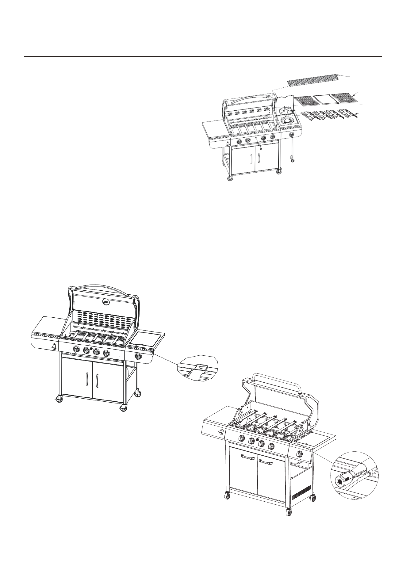
Removing The Burner Assembly - Make sure the grill is cool
Insulated Rack
Cooking
Comal
Grill
Fire Spreader
Figure 1
8. Ensure the burner is free of any damage. If any damage is found, replace it with a new burner.
9. Ensure the end of the burner and the primary air screen at the back of the grill body are clear
1. Make sure all control knobs are in the
“OFF”
position, the gas supply valve is closed, and the
gas hose is disconnected from the gas supply.
2.Remove the ignition button, remove the AA
battery (1.5V) (K) out, then screw the ignition
button in.
3.Remove the insulated rack, cooking grills,
comal, fire spreaders and burner rack.
4.Remove the hinge pins at end of the main burners
as illustrated in Figure 1. Then remove the screws
of the side burner.
5.Slide the main burners and the side burner out.
6. Detach the ignition wire from the electrode in Figure 2. DO NOT use pliers or any other tool
as itmay damage the electrode or wire.
7. Ensure all burner ports are clear of clogs. Use of a pin or a paper clip works well.
of insect nests, dirt or debris.
3.Remove the warming rack, cooking grates,
grill heat plate, cooking plate and burner rack.
Warming Rack
Cooking Grate
Grill Heat Plate
Cooking Plate
27
View the correct position
Bottom View
Wrong
Wrong
burner inlet
gas valve orifices
Correct
WARNING
may
r
esult
,
po
s
sibly
causing serious bodily injury.
Other Care and Maintenance
ing
K
ing
C
1. Ensure that gas value orifices inside the grill body are correctly positioned inside burner inlet
(venturi) as shown in the right pictures below.
2. The use of a flashlight may be necessary to ensure the correct position.
3. It is recommended to view the correct position through the firebox vent holes as shown in the left
pictures below.
4. Reattach each burner with the hinge pin and reattach the ignition wire to electrode.
5. Ensure that the side burner is correctly attached to the valve of the hose and reattached on
the right burner table with screws.
CARE AND MAINTENANCE
Re-installing the Burner Assembly
.
The electronic ignition requires 1 “AA” alkaline battery, which is included.
WARNING
DO NOT mix old and new batteries.
DO NOT mix alkaline, standard (Carbon-Zinc), or rechargeable (Nickel-Cadmium) batteries.
2
8
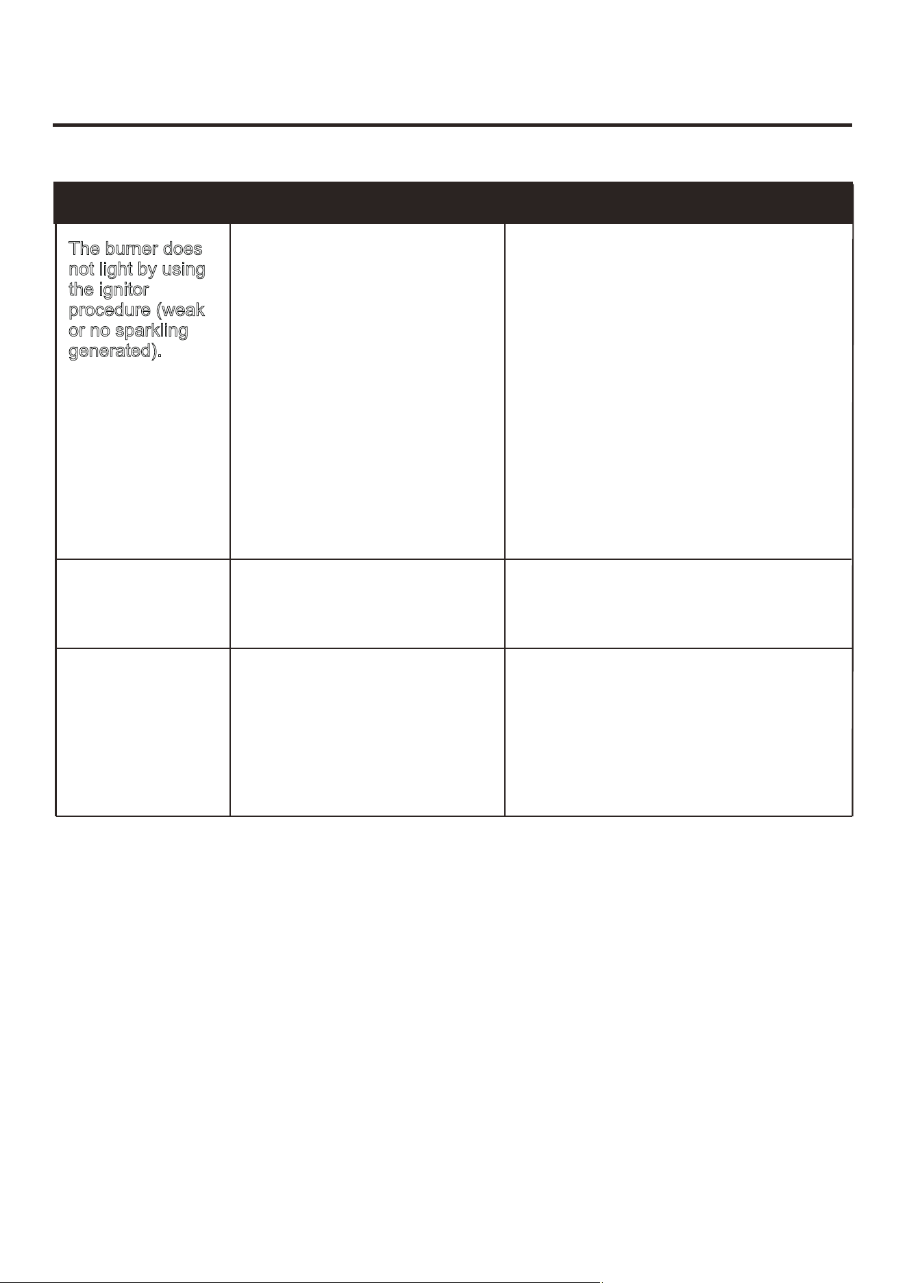
TROUBLESHOOTING
PROBLEM POSSIBLE CAUSE CORRECTIVE ACTION
Excessive
Flare Ups
Low Heat.
.
1.
The ignition electrode may
be
covered with grease or residue.
1. Insufficient gas pressure to
the unit.
3. Replace the ignition electrode.
3. Cracked or broken ignition
1. Clean the grill components.
2. Shed the fat from meat and use
non-oil based marinades.
4. Perform any of the following:
3. Lower temperature accordingly.
electrode.
1. Grease and/or residue build-up
on grill heat plates or in firebox.
2. Excessive dripping of fat or
marinade from food.
3. Cooking temperature too high.
1. Call a qualified service agency to
check the gas supply pressure and
correct the pressure.
1. Clean the ignition electrode.
2. Check the connection and reconnect
any loose or disconnected wire.
a.Replace the battery.
b.Check to see if the battery is
inserted correctly.
c.Check for any corrosion around ba-
ttery terminals.
The burner does
n
ot light by using
t
he ignitor
p
rocedure (weak
o
r no sparkling
2. The ignition electrode may
have a loose or disconnected
wire.
4. Dead battery or faulty battery
con
If you have any question regarding the product, please call customer service at
818-468-1498.
nection.
g
enerated).
1. Tank valve not on or fully opened.
2. Empty tank.
3. Poor connection between the
valve regulator and the LP cylinder
coupling.
4. Burner inlet blocked.
29
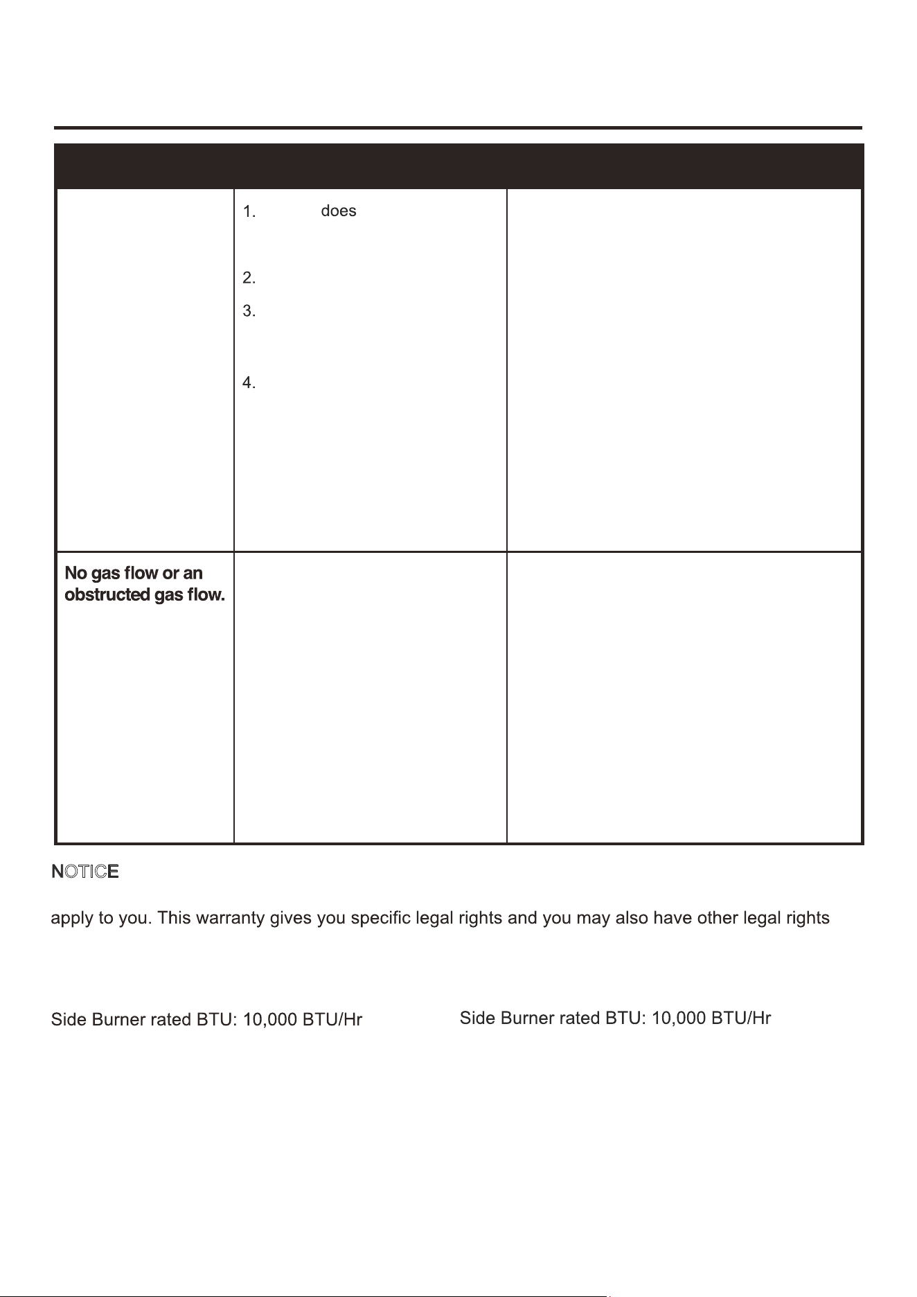
TROUBLESHOOTING
PROBLEM POSSIBLE CAUSE CORRECTIVE ACTION
The burner will not
light with the fire rod
NOTICE: Some states do not allow the exclusion or limitation of incidental or consequential damages
or limitations on how long an implied warranty lasts, so the above limitations or exclusions may not
which may vary from state to state.
Model #:
JD-3A
Main Burner Total rated BTU: 24,000 BTU/Hr
The rod
not reach
burners (when holding the rod
with hand).
Empty tank.
Poor connection between the
regulator valve and the threaded
valve of the LP gas cylinder.
Burner inlet blocked.
1. Use the fire rod correctly as instructed in
LIGHTING THE GRILL WITH THE FIRE ROD
section.
2. Check the fuel level and replace the tank if
necessary.
3. Turn off grill knobs, close the cylinder valve
and check the
connection between the
regulator valve and the threaded valve of the
LP gas cylinder.
Disconnect and reconnect, if necessary.
4. Clean the burner inlet (venturi) and the
burner as described by Care and
Maintenance section in the manual.
1. Fully open the tank valve by turning
counterclockwise.
2. Check the fuel level and replace the fuel if
necessary.
3. Turn off grill knobs, close the LP cylinder
valve and check the regulator valve and the
threaded valve of the LP gas cylinder.
Disconnect and reconnect, if necessary.
4. Clean the burner inlet (venturi) and burners
as described by Care and Maintenance
section in the manual.
Model #: JD-4A
Main Burner Total rated BTU: 32,000 BTU/Hr
IMPORTANT
Simply call our customer service department for any consulting:
(8:30am - 5:30pm P.S.T.)
DATED PROOF OF PURCHASE IS REQUIRED FOR WARRANTY
SERVICE.
AVIS
Veuillez appeler le service à la clientèle pour toutes questions au:
(8:30am - 5:30pm P.S.T.)
PREUVE D’ACHAT ORIGINALE REQUISE POUR SERVICE DE
GARANTIE.
IMPORTANTE
(8:30am - 5:30pm P.S.T.)
SE REQUIERE PRUEBA DE COMPRA CON FECHA PARA SERVICIO
BAJO GARANTÍ
Sólo hay que llamar nuestro departamento de servicio
al cliente en cas
o de tener preguntas o i
nquietudes:
A.
Thank you for purchasing this product! If you have any question
about the product such as missing parts, damaged products,
product assembling, operation, please contact us via our
customer service phone: 818-468-1498.
818-468-1498
818-468-1498
818-468-1498