

P3 PowerPort Family
P3 PowerPort 2000
P3 PowerPort 500 IP Rental
P3 PowerPort 500 IP Install
Installation, Safety
and User Manual
P3 PowerPort 2000
P3 PowerPort 500 IP Rental
P3 PowerPort 500 IP Install
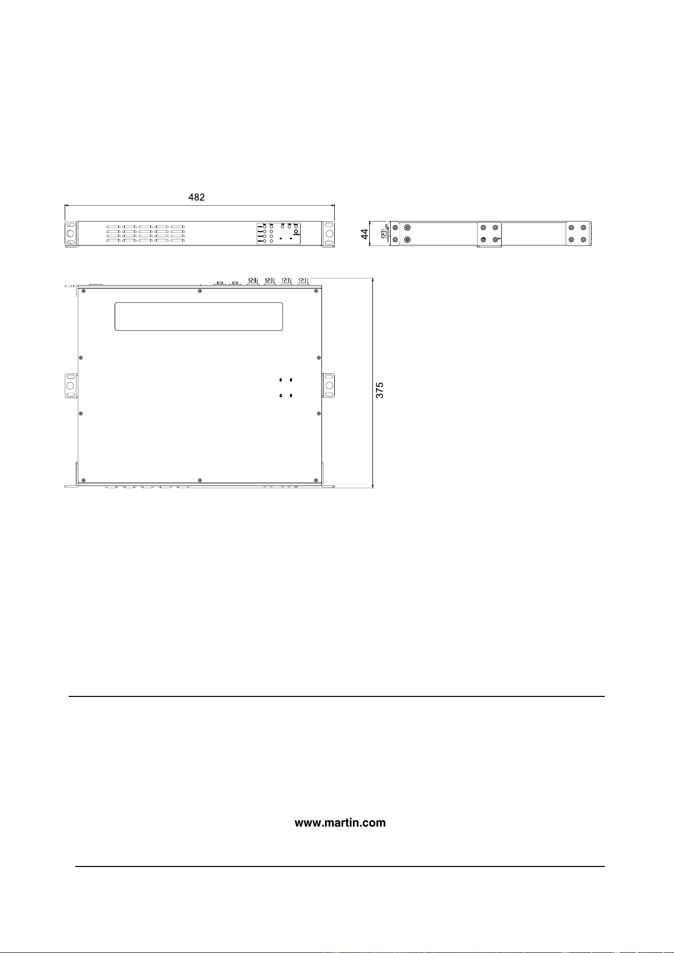
Dimensions
P3 PowerPort 2000
©2023-2024 HARMAN PROFESSIONAL DENMARK ApS. All rights reserved. Features, specifications and
appearance are subject to change without notice. HARMAN PROFESSIONAL DENMARK ApS and all affiliated
companies disclaim liability for any injury, damage, direct or indirect loss, consequential or economic loss or any other
loss occasioned by the use of, inability to use or reliance on the information contained in this document. Martin is a
registered trademark of HARMAN PROFESSIONAL DENMARK ApS registered in the United States and/or other
countries.
HARMAN PROFESSIONAL DENMARK ApS, Olof Palmes Allé 44, 8200 Aarhus N, Denmark
HARMAN PROFESSIONAL, INC., 8500 Balboa Blvd., Northridge CA 91329, USA
P3 PowerPort 2000/500 IP Installation, Safety and User Manual English Rev. B Multi-Language, P/N 5143255-00
Rev. B
All measurements are in
millimeters
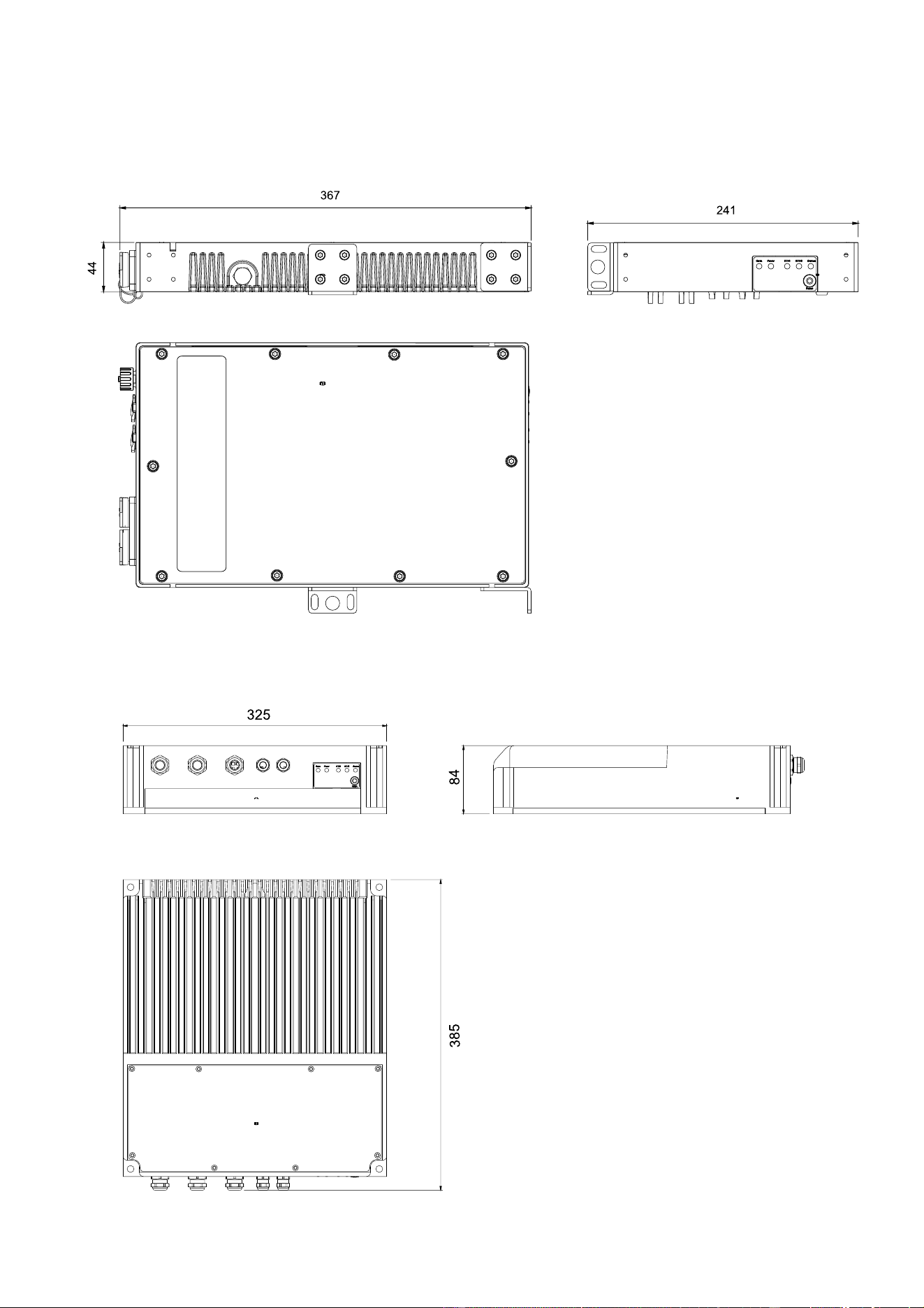
P3 PowerPort 500 IP Rental
P3 PowerPort 500 IP Install
All measurements are in
millimeters

Contents
Dimensions ...................................................................................................................................... 2
Safety information ........................................................................................................................... 5
Introduction ...................................................................................................................................... 9
Unpacking .................................................................................................................................. 9
Accessories and related items ................................................................................................. 10
Status LEDs and switchable options ........................................................................................ 10
P3 PowerPort 2000 ....................................................................................................................... 11
Overview .................................................................................................................................. 11
Installing ................................................................................................................................... 11
Connecting the device .............................................................................................................. 12
Status LED and power mode settings ...................................................................................... 12
Operating .................................................................................................................................. 12
P3 PowerPort 500 IP Rental ......................................................................................................... 13
Overview .................................................................................................................................. 13
Installing ................................................................................................................................... 14
Connecting the device .............................................................................................................. 16
Status LED and power mode settings ...................................................................................... 16
Operating .................................................................................................................................. 16
P3 PowerPort 500 IP Install .......................................................................................................... 17
Overview .................................................................................................................................. 17
Installing ................................................................................................................................... 17
Cables and cable glands .......................................................................................................... 18
Opening the connections compartment ................................................................................... 18
Connecting and setting up the device ...................................................................................... 18
Status LED and power mode settings ...................................................................................... 21
Closing the connections compartment ..................................................................................... 21
Operating .................................................................................................................................. 21
Status LEDs and Test/Reset button .............................................................................................. 22
Service and maintenance .............................................................................................................. 23
Cleaning ................................................................................................................................... 23
Pressure equalization valves ................................................................................................... 23
Installing firmware .................................................................................................................... 24
Troubleshooting ............................................................................................................................. 25
Martin
®
P3 PowerPort 2000 and 500 IP Safety, Installation and User Manual 5
Safety information
WARNING!
Read the safety precautions in this section before installing,
operating or servicing this product.
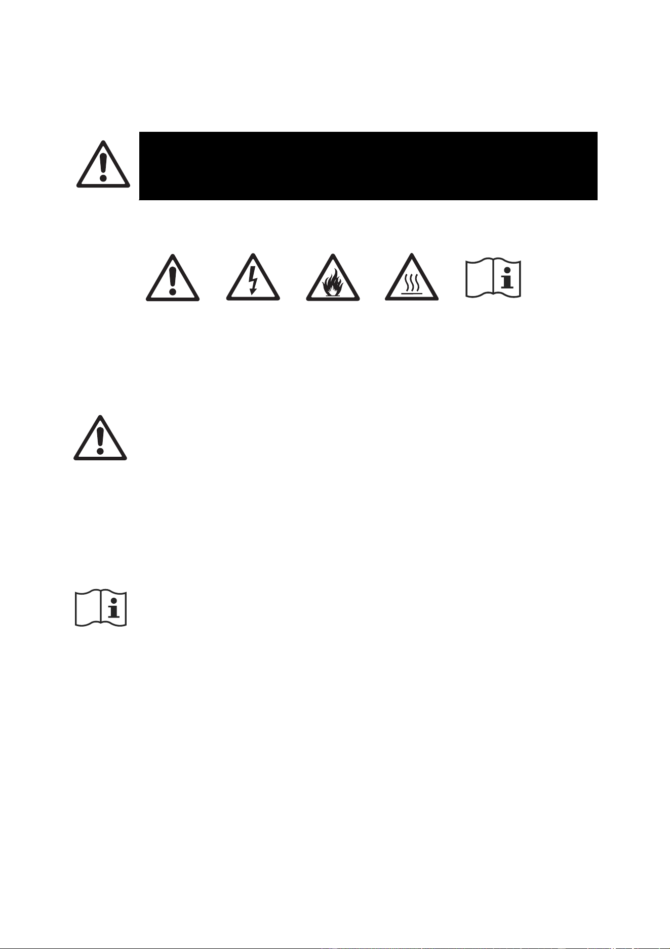
The following symbols are used to identify important safety information on the product and in this manual:
Warning!
Safety hazard.
Risk of severe
injury or death.
Warning!
Hazardous
voltage. Risk
of lethal or
severe electric
shock.
Warning!
Fire hazard.
Warning!
Burn hazard.
Hot surface.
Do not touch.
Warning!
See user
documentation.
Warning! This product presents risks of severe injury or death due to fire and burn hazards,
electric shock and falls if the safety precautions in this manual are not followed. Read this
manual before installing, operating or servicing the product. Follow the safety precautions
given not only in this user manual but also in the manuals of all the devices you connect to
the product. Observe all warnings given in the manuals and printed on devices.
The products in the P3 PowerPort family are for professional use only. They are not for
household applications. They must be installed and serviced by professional technicians
only. Respect all locally applicable laws, codes and regulations when installing, operating or
servicing the products.
Refer any service operation that is not described in this user manual to Martin
®
Service or
an authorized Martin Service partner.
Install, operate and service Martin products only as directed in their user documentation, or
you may create a safety hazard or cause damage that is not covered by product warranties.
Follow the safety precautions listed in the following section and observe all warnings in this
manual and printed on the product.
The latest version of this User Manual is available for download from the Martin website at
www.martin.com. Before you install, operate or service the product, check the Martin
website and make sure that you have the latest user documentation for the fixture.
Document revisions are indicated at the bottom of page 2.
Technical Support
If you have questions about how to install or operate the product safely, please contact
Harman Professional Technical support:
For technical support in North America, please contact:
HProTechSupportUSA@harman.com
Phone: (844) 776-4899
For technical support outside North America, please contact your national distributor.

6 Martin
®
P3 PowerPort 2000 and 500 IP Safety, Installation and User Manual
Protection from electric shock
Connect P3 PowerPort products to AC mains power within these ranges only:
• P3 PowerPort 2000 – 100-240 V~ (nominal), 50/60 Hz
• P3 PowerPort 500 IP Rental – 100-240 V~ (nominal), 50/60 Hz
• P3 PowerPort 500 IP Install – 100-277 V~ (nominal), 50/60 Hz
Ensure that each of these products is electrically connected to ground (earth).
Use only a source of mains power that complies with local building and electrical codes and
has both overload and ground-fault (earth-fault) protection.
Follow your local AC mains power wire color coding system when connecting to AC mains
power. In the USA and EU, mains power wiring is color coded as follows:
Earth, Ground or
Neutral or N
Live or L
US system
Green
White
Black
EU system
Yellow/green
Blue
Brown
Socket outlets or external power switches used to supply these products with power must be
located near the product and easily accessible so that the product can easily be
disconnected from power.
Provide a means of locking out AC mains power so that power to the installation can be shut
down and made impossible to reapply, even accidentally, during work on the installation.
Isolate the product from power immediately if the power plug or any seal, cover, cable, or
other component is damaged, defective, deformed or showing signs of overheating. Do not
reapply power until repairs have been completed.
Do not expose connectors or cable glands to stresses caused by lengths of cable hanging
from them or by tight cable bends. Support the weight of cables running to and from
products.
The P3 PowerPort 2000 is IP20-rated and is suitable for indoor installation only. Do not
expose this device to rain or moisture. Isolate it from power immediately if the device or
connections become wet.
The P3 PowerPort 500 IP Rental is IP65-rated and is suitable for temporary and permanent
indoor installation and temporary outdoor installation only.
The P3 PowerPort 500 IP Install is IP66-rated and is suitable for temporary and permanent
indoor and outdoor installation.
Do not expose an IP65- or IP66-rated product to high-pressure water jets from any direction.
When installing an IP65- or IP66-rated product, create a
‘drip loop’ in cables (see illustration on right) so that they
arrive at cable glands or connectors from below.
Do not allow water to pool around the pressure
equalization valve of an IP65- or IP66-rated product. Make
a visual check of the pressure equalization valve
periodically. If a valve appears to be dirty it may be
blocked. Consult your Martin supplier for replacement.
Before using a P3 PowerPort or accessory device, check
that all power distribution equipment and cables are in
perfect condition and rated for the electrical requirements
of all connected devices.
Disconnect products from AC mains power and ensure that power cannot be reconnected
before carrying out any installation or maintenance work and when the product is not in use.
Drip loop

Martin
®
P3 PowerPort 2000 and 500 IP Safety, Installation and User Manual 7
Do not connect products to mains power in a daisy chain that will exceed the electrical
ratings of any device, cable or connector in the chain.
Check and respect the directions given in the user manuals of all the devices that you intend
to connect to a P3 PowerPort or accessory product. Pay particular attention to the
instructions and warnings that apply to:
• system layout,
• connections to other devices,
• specified cables,
• maximum cable lengths, and
• maximum number of devices that can be connected.
P3 PowerPort 500 and P3 PowerPort 2000 products can supply a safe maximum current of
10 A and safe maximum power of 480 W per hybrid (combined DC power and P3 data)
output. Do not connect a device or a chain of devices to a hybrid output if this safe
maximum current or power limit will be exceeded.
The external diameter of the cables used to connect P3 PowerPort 500 IP Install devices to
power and data must be suitable for the cable glands provided, or water can enter the
product and create a safety hazard or cause damage. The cables must have the following
external diameter:
• AC mains power in, AC mains power THRU: 8-13 mm (0.32-0.51 in.)
• Hybrid (48 VDC power and P3 data) OUT: 6.5-10.5 mm (0.26-0.41 in.)
• P3 data IN, P3 data THRU: 5-8 mm (0.2-0.32 in.)
To connect P3 PowerPort and related devices to AC mains power in a chain, you must use
12 AWG or 2.5 mm
2
power input and throughput cable that is 16 A rated and temperature-
rated to suit the application. In the USA and Canada the cables must be UL-listed, type SJT
or equivalent. In the EU the cables must be type H05VV-F or equivalent. Suitable cable and
loose Neutrik powerCON TRUE1 TOP connectors are available from Martin (see the P3
PowerPort product pages on the Martin website at www.martin.com)
Connect only Neutrik powerCON TRUE1 TOP cable connectors to the AC mains power
sockets of P3 PowerPort products.
You can connect P3 PowerPort 500 IP Install and P3 PowerPort 500 IP Rental products to
AC mains power in an interlinked daisy chain in which you connect one device’s mains
power THRU socket to the next device’s mains power IN socket, but you must respect the
following limits:
• When operating at 100-120 V~ do not interlink more than three (3) P3 PowerPort 500 IP
devices in total in a daisy chain.
• When operating at 200-240 V~ do not interlink more than five (5) P3 PowerPort 500 IP
devices in total in a daisy chain.
• The P3 PowerPort 500 IP Install can also be operated at 200-277 V~. Do not interlink
more than five (5) P3 PowerPort 500 IP Install devices in total in a daisy chain when
operating this device within this voltage range.
• Regardless of which devices you connect in a daisy chain using a P3 PowerPort 500 IP
device’s THRU socket, do not exceed a total current draw of 16 A for all the devices in
the chain, including the first P3 PowerPort 500 IP device.
The voltage and frequency at the mains power THRU socket are the same as the voltage
and frequency applied to the mains power IN socket. Only connect devices to the mains
power THRU socket that accept this voltage and frequency.

8 Martin
®
P3 PowerPort 2000 and 500 IP Safety, Installation and User Manual
Protection from burns and fire
Do not operate a device in this range of products if the maximum ambient temperature
(T
a
max.) exceeds the levels shown below:
• P3 PowerPort 2000: 40° C (104° F)
• P3 PowerPort 500 IP Rental: 40° C (104° F)
• P3 PowerPort 500 IP Install: 55° C (131° F)
When using rack-mounted products, make sure that the rack used is well ventilated. Provide
fan cooling in the rack if the ambient temperature can exceed 40° C (104° F).
The surface of the products can reach the following maximum temperatures during
operation.
• P3 PowerPort 2000: 62° C (144° F)
at full load, ambient temperature 40° C (104° F)
• P3 PowerPort 500 IP Rental: 65° C (149° F)
at full load, ambient temperature 40° C (104° F)
• P3 PowerPort 500 IP Install: 70° C (158° F)
at full load, ambient temperature 55° C (131° F)
Avoid contact by persons and materials. Allow the product to cool for at least 15 minutes
before handling.
Keep flammable materials well away from the product. Keep all combustible materials (e.g.
fabric, wood, paper) at least 0.5 m (1.7 ft.) away from the product.
Ensure that there is free and unobstructed airflow around the product. Provide a minimum
clearance of 0.5 m (1.7 ft.) around fans and air vents.
Protection from injury
Fasten the product securely to a fixed surface or structure when in use. The product is not
portable when installed.
Ensure that any supporting structure and/or hardware used can hold at least six (6) times –
or more if required by local regulations – the weight of all the devices and other items that
they support.
Use rigging hardware and fasteners that are in perfect condition, approved for the weight
that they will support, and suitable for their application and the installation environment. Do
not use safety cables as the primary means of support.
If the product is installed in a location where it may cause injury or damage if it falls, install
as directed in this manual a secondary attachment such as a safety cable that will hold the
product if a primary attachment fails. The secondary attachment must be approved by an
official body such as TÜV as a safety attachment for the weight that it secures, must comply
with EN 60598-2-17 Section 17.7.4 and must be capable of bearing a static suspended load
that is six (6) times – or more if required by local regulations – the weight of the product and
all installed accessories.
Check that all external covers and rigging hardware are securely fastened.
Block access below the work area and work from a stable platform whenever installing,
servicing or moving an overhead product.
Do not operate the product with missing or damaged covers.
In the event of an operating problem, stop using the product immediately and disconnect it
from power. Do not attempt to use a product that is obviously damaged.
Do not modify the product in any way not described in this manual. Install genuine Martin
parts only.
Refer any service operation not described in this manual to Martin Service or one of its
authorized agents.

Martin
®
P3 PowerPort 2000 and 500 IP Safety, Installation and User Manual 9
Introduction
Thank you for selecting a product from the Martin P3 PowerPort family. These units supply low voltage
power and data to a wide range of Martin Creative LED fixtures. The following devices are available:
• P3 PowerPort 2000 – IP20, indoor use, 4 hybrid DCE outputs towards fixtures, rack/surface/truss-
mount.
• P3 PowerPort 500 IP Rental – IP65, temporary outdoor use, 1 hybrid DCE output towards fixtures,
rack/surface/truss-mount.
• P3 PowerPort 500 IP Install – IP66, permanent outdoor use, 1 hybrid output towards fixtures, surface-
mount, features service compartment to terminate cables on site.
Additionally, two accessories are available for this ecosystem:
• DCE PSU 240 IP – for powering Martin Creative LED fixtures without the advanced features offered by
the P3 PowerPorts listed above.
• DCE Data Splitter/Booster IP – for extending the distance between a P3 PowerPort and Martin
Creative LED fixtures and/or split chains of fixtures.
See the separate user documentation for these two accessories.
P3 PowerPorts (and connected Martin Creative LED fixtures) are compatible with Art-Net, sACN and the
Martin P3 protocol. They provide local status information via status LEDs and can test the connected
fixtures via integrated test buttons. Additionally, the P3 PowerPorts are able to force the connected
Creative LED fixtures into low-power mode, which enables longer daisy-chains with more fixtures to be
created and reduces the number of P3 PowerPorts required in a given installation.
P3 PowerPorts incorporate a network switch with fail-safe bypass mechanism, enabling easy daisy-
chaining of P3 PowerPorts with zero risk (a P3 PowerPort losing power will not interrupt the network
connection to the P3 PowerPorts chained downstream of it).
P3 PowerPorts support full monitoring and control settings via P3 and RDM over Art-Net.
For possible system layouts when using the P3 PowerPorts with Martin Creative LED fixtures, please see
the user documentation for those products. Martin user documentation is supplied with products and
available for download from the Martin website at www.martin.com , where you can also find the latest
specifications, software/firmware updates and support information for all Martin products.
Unpacking
This user manual is supplied with each product. The following items are also included:
P3 PowerPort 2000
• Safety Cable Attachment Bracket (screws included)
• 2 x Short Rack Mounting Ears (screws included)
P3 PowerPort 500 IP Rental
• Safety Cable Attachment Bracket (screws included)
• 2 x Short Rack Mounting Ears (screws included)
• Long Rack Mounting Ear (screws included)
• Coupling Plate (screws included)
P3 PowerPort 500 IP Install
• Blanking plugs in all pre-installed cable glands
Power input cable
For the P3 PowerPort 2000 and the P3 PowerPort 500 IP Rental, either a mains power cable complete
with Neutrik PowerCON TRUE1 power input connector or a separate Neutrik PowerCON TRUE1 power
input connector should be ordered separately from Martin. For the P3 PowerPort 500 IP Rental the

10 Martin
®
P3 PowerPort 2000 and 500 IP Safety, Installation and User Manual
connector must be TOP (True Outdoor Protection) type. See the P3 PowerPort product pages on the
Martin website at www.martin.com for details of cables and connectors available from Martin.
No input connector is required for the P3 PowerPort 500 IP Install power input cable, as this device is
designed to be hard-wired using internal terminals during installation.
Accessories and related items
Martin can supply a comprehensive range of cables, connectors, rigging hardware and other accessories
for the products in Martin P3 systems. The accessories listed in the Specifications sections of the related
areas of the Martin website at www.martin.com give details. Your Martin supplier will also be happy to help
if you would like assistance with assessing your needs and ordering.
Status LEDs and switchable options
The three P3 PowerPort devices covered by this manual have the following features:
Status LEDs
The status LEDs light when a signal is present and flash when data is being received or transmitted. They
also give device status information. See ‘Status LEDs and Test/Reset button’ on page 22 for more details.
Switches
The two switches on or inside the device have the following functions:
• FRONT PANEL ON/OFF – disables all the status LEDs and disables the Test/Reset button (see
‘Status LEDs and Test/Reset button’ on page 22). Setting this switch to OFF reduces the visibility of
the device in the installation and protects from accidental resets or tampering.
• POWER CONTROL/FULL/HALF – offers three settings that apply to all connected compatible Martin
Creative LED fixtures:
- FULL forces all fixtures to run in full-power mode, overriding any power mode commands from the
P3 System Controller, Art-Net controller, sACN controller or RDM controller.
- HALF forces all fixtures to run in half- or low-power mode, overriding any power mode commands
from the P3 System Controller, Art-Net controller, sACN controller or RDM controller.
- CONTROL allows the P3 System Controller, Art-Net controller, sACN controller or RDM controller
to set the fixtures’ power modes.
Setting fixtures to low power can be useful for nighttime or TV studio applications, for example, where
full power is not needed or may be undesirable. The HALF setting also lets you connect a higher
number of fixtures to the hybrid output, meaning that an installation will require fewer P3 PowerPort
devices.
Note that when the POWER CONTROL switch is set to FULL or HALF, it is not possible to adjust the
power mode from the P3 System Controller, Art-Net controller, sACN controller or RDM controller.

Martin
®
P3 PowerPort 2000 and 500 IP Safety, Installation and User Manual 11
P3 PowerPort 2000
Overview
Front panel
The front panel of the P3 PowerPort 2000 features status LEDs and a single button that runs test
sequences or reboots the device (see ‘Status LEDs and Test/Reset button’ on page 22).
Rear panel
The rear panel of the P3 PowerPort 2000 features the following:
• Hybrid (48 VDC power and data) outputs (7-pin DCE connectors)
• Network data in/thru ports A and B (Neutrik etherCON connectors)
• Switch that disables status LEDs and Test/Reset button
• Switch that manages the power level of the fixtures on the hybrid links
• AC mains power in (Neutrik PowerCon TRUE1 TOP connector)
Installing
Read the ‘Safety Information’ section starting on page 5 before installing, applying power to or operating
the device.
The P3 PowerPort 2000 is designed to be installed in a 19-inch rack, on a rigging truss or on a flat surface
in any orientation.
Rack mounting
To mount the P3 PowerPort 2000 in a 19-inch rack:
1. Fasten the two supplied short rack ears to the front of the device as shown in the illustration above
using the supplied screws. Do not fasten the supplied safety cable attachment bracket to the device.
2. Fasten the device into the rack. Bear in mind the need for good ventilation and the possible need for
fan cooling.
Hybrid outputs
Ethernet
IN/THRU
Switches
Mains
power IN
Status LEDs
Test/Reset
button
12 Martin
®
P3 PowerPort 2000 and 500 IP Safety, Installation and User Manual
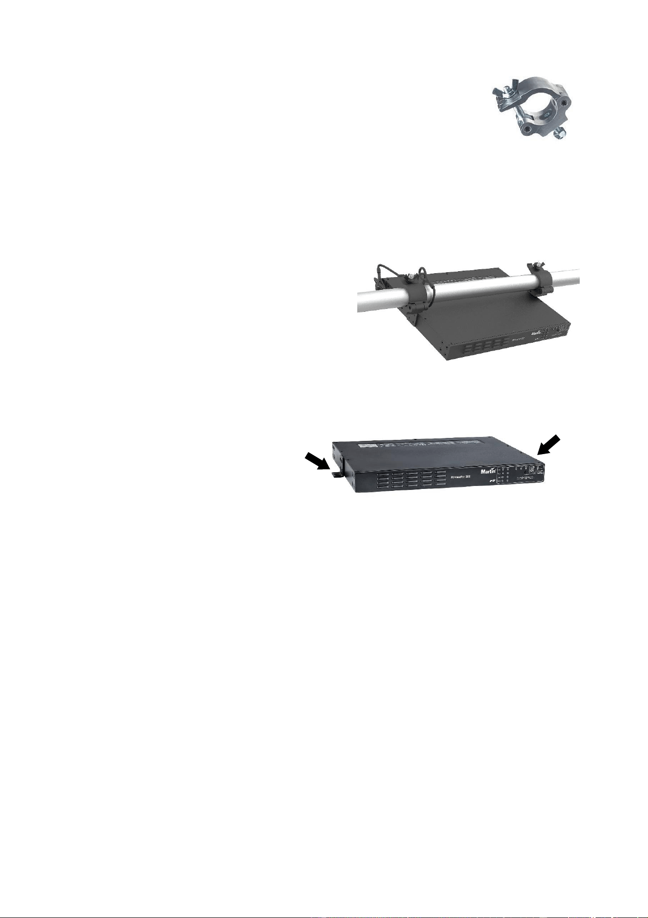
Truss mounting
When installing the P3 PowerPort 2000 on a rigging truss, use half-coupler type
rigging clamps (see Figure 1) that completely encircle the truss chord. Rigging
clamps must be in perfect condition and approved for the weight that they will
support.
To mount the device on a rigging truss, see Figure 2:
1. Using the four screws supplied for each ear, fasten the two supplied short rack
ears to the sides of the device at the edges of the top surface as shown in
Figure 2.
2. Using both the supplied screws, fasten the safety cable attachment bracket to
the back of the device as shown in Figure 2.
3. Using hardened steel fasteners with locking nuts, fasten two rigging clamps that are approved for the
weight that they will support to the two short rack ears.
4. Install the device on the truss by fastening the rigging
clamps onto the truss chord.
5. If there is any risk that the device may cause injury or
damage if it falls, secure it by fastening an approved
safety cable to the safety cable attachment bracket
and looping it around the truss or other secure
anchoring point. Remove as much slack as possible
from the safety cable by looping it more than once
around the truss chord, for example.
Surface mounting
To mount the P3 PowerPort 2000 on a secure, flat surface:
1. See illustration on right. Using the four
screws supplied for each ear, fasten
the two supplied short rack ears to the
device as shown. The safety cable
attachment bracket is not required.
2. Fasten the device to the surface using
suitable screws or bolts passed
through the short rack ears and
fastened into the mounting surface.
Connecting the device
Use the connectors that are specified for the P3 PowerPort 2000 to connect to AC mains power, network
data and the hybrid link. Connectors are labeled on the device and shown in ‘Rear panel’ on page 11.
Status LED and power mode settings
The two switches located on the rear panel let you manage the status LEDs and Test/Reset button on the
front panel, and manage the power setting of connected fixtures (see ‘Switches’ on page 10).
Operating
When power is applied to the power input cable, the device carries out a short boot procedure and then
becomes operational. There is no power on/off switch.
Status LEDs and Test/Reset button
You can monitor operation via the status LEDs on the front panel if they are activated using the switch on
the rear panel.
You can send test patterns to connected Martin Creative LED fixtures and reboot the device using the
Test/Reset button on the front of the device.
See ‘Status LEDs and Test/Reset button’ on page 22 for details of these two features.
Figure 1. Half-
coupler rigging
clamp
Figure 2. Truss mounting
Figure 3. Surface mounting
Martin
®
P3 PowerPort 2000 and 500 IP Safety, Installation and User Manual 13
P3 PowerPort 500 IP Rental
Overview
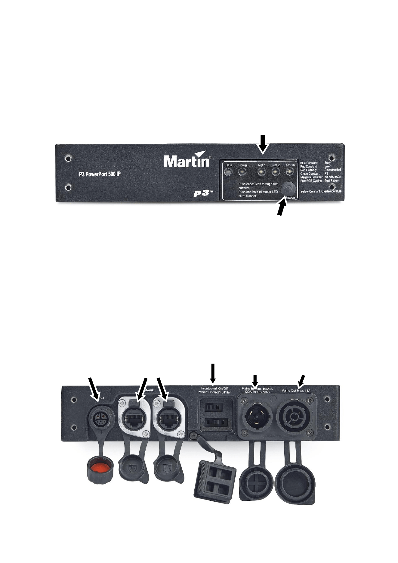
Front panel
The front panel of the IP65-rated P3 PowerPort 500 IP Rental features status LEDs and a single button
that runs test sequences. If you push and hold this button, it resets the product.
Rear panel
The rear panel of the P3 PowerPort 500 IP Rental features the following:
• Hybrid (48 VDC power and data) output (7-pin DCE connector)
• Network data in/thru A and B (Neutrik etherCON TOP connectors)
• Switch that disables status LEDs and Test/Reset button
• Switch that manages the power level of fixtures on the hybrid link
• AC mains power IN and OUT/THRU (Neutrik PowerCon TRUE1 TOP connectors)
Hybrid (48 VDC
power and data)
OUT
Network
data ports
A and B
AC mains
power
IN
AC mains
power
OUT/THRU
Switches
Status LEDs
Test/Reset
button
14 Martin
®
P3 PowerPort 2000 and 500 IP Safety, Installation and User Manual
Side panel
The P3 PowerPort 500 IP Rental has a pressure equalization valve on the side of the device (see
illustration). Check this valve visually from time to time. If it appears to be dirty, consult Martin Service for
possible replacement
Installing
Read the ‘Safety Information’ section starting on page 5 before installing, applying power to or operating
the device.
The P3 PowerPort 500 IP Rental is designed to be installed in a 19-inch rack, on a rigging truss or on a
flat surface in any orientation.
Rack mounting
To mount one single P3 PowerPort 500 IP Rental in a 19-inch rack:
1. Fasten one short rack ear (supplied) and one long rack ear (supplied) to the front of the device using
the supplied screws. Do not fasten the supplied safety cable attachment bracket to the device.
2. Fasten the device into the rack. Bear in mind the need for good ventilation and the possible need for
fan cooling.
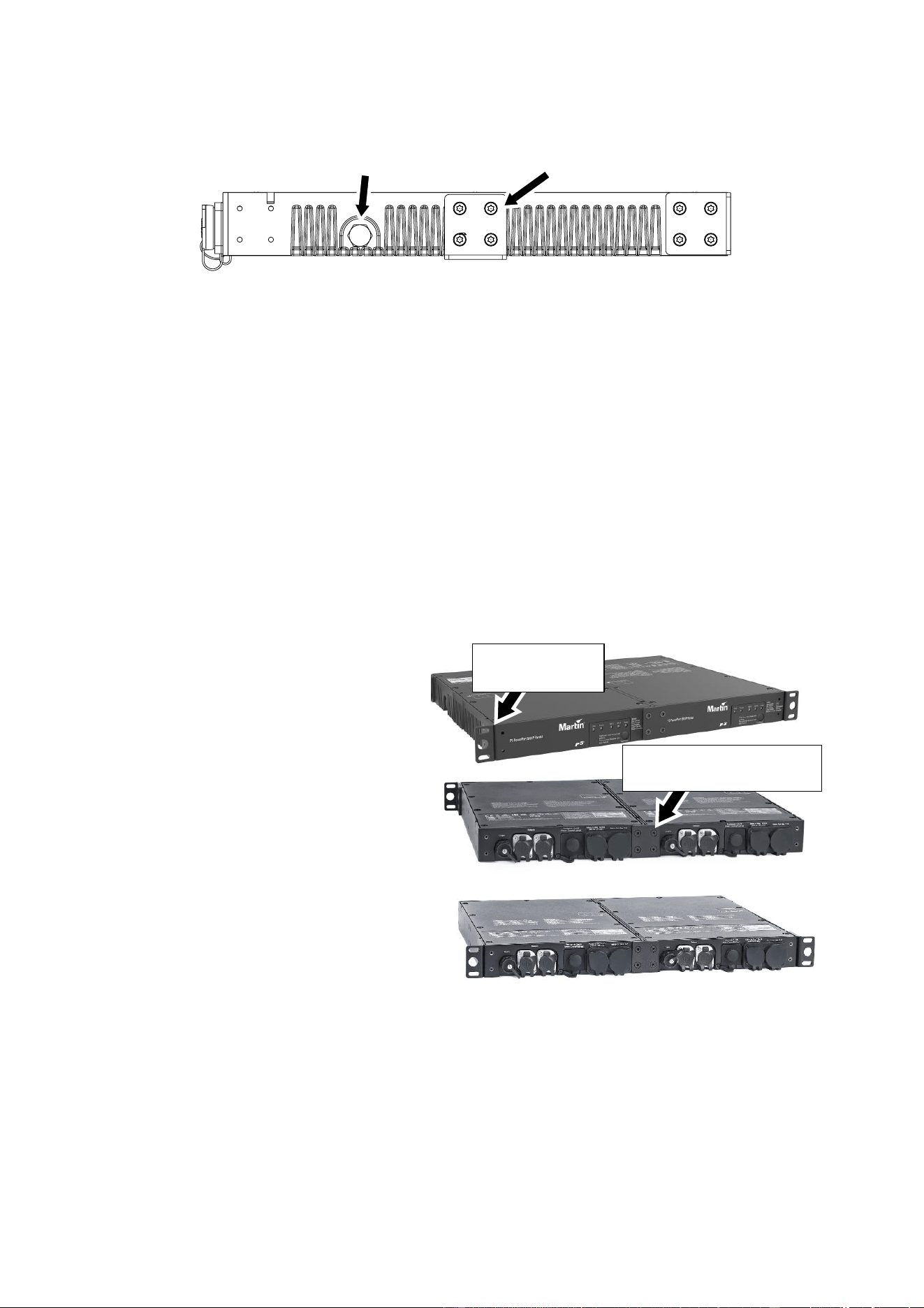
To mount two P3 PowerPort 500 IP Rental
devices side-by-side in a 19-inch rack:
1. See illustrations on right. Fasten the two
devices together by fastening the two
supplied coupling plates to the devices,
one plate on the front and one plate on
the rear, using the supplied screws.
2. Fasten the two supplied short rack
mounting ears to the devices using the
supplied screws. Note that you can
rackmount the devices with the
connections panel at the front or at the
rear of the rack, but if you mount them at
the front the status LEDs and Test/Reset
button will be less accessible. Do not
fasten the supplied safety cable
attachment bracket to the devices.
3. Fasten the two devices into the rack.
Bear in mind the need for good
ventilation and the possible need for fan
cooling.
Truss mounting
When installing the P3 PowerPort 500 IP Rental on a rigging truss, use half-coupler type rigging clamps
(see Figure 1 on page 12) that completely encircle the truss chord. Rigging clamps must be in perfect
condition and approved for the weight that they will support.
You can install the P3 PowerPort 500 IP Rental on a rigging truss either mounted horizontally or hanging
vertically.
Pressure
equalization valve
Rigging
bracket
Short rack
mounting ear
Coupling plate for side-
by-side rack mounting
Martin
®
P3 PowerPort 2000 and 500 IP Safety, Installation and User Manual 15
To mount the device horizontally on a rigging truss:
1. Using both the supplied screws, fasten the safety cable attachment bracket to the back of the device.
2. Using the four supplied screws for each ear, fasten the two supplied short rack ears to the sides of the
device at the edges of the top surface.
3. Using hardened steel fasteners with locking nuts, fasten two half-coupler type rigging clamps that are
approved for the weight that they will support to the two short rack ears.
4. Install the device on the truss by fastening the rigging clamps onto the truss chord.
5. If there is any risk that the device may cause injury or damage if it falls, secure it by fastening an
approved safety cable to the safety cable attachment bracket and looping it around the truss or other
secure anchoring point. Remove as much slack as possible from the safety cable by looping it more
than once around the truss chord, for example.
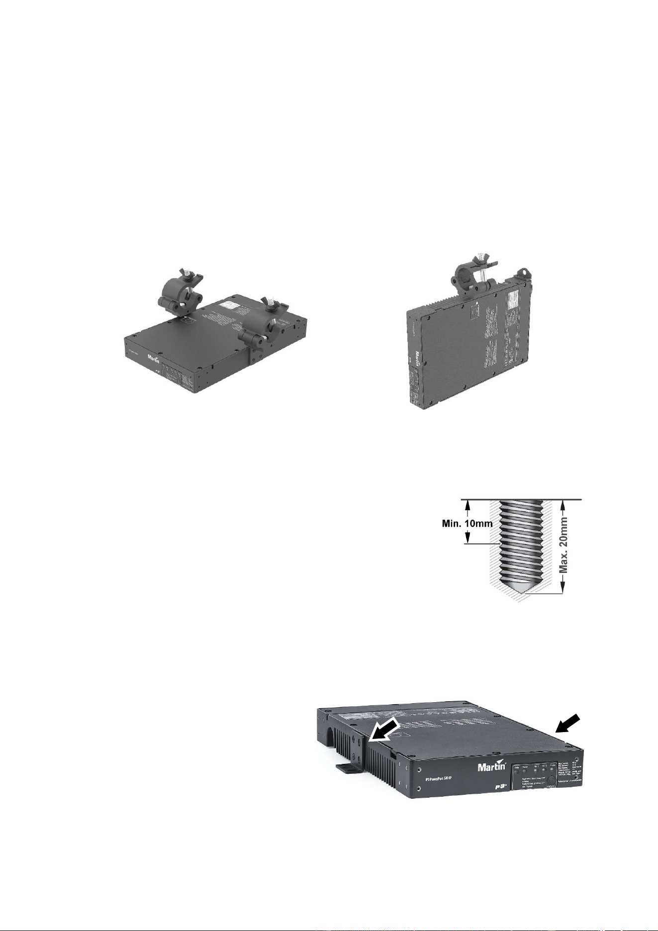
To mount the device hanging vertically downwards on a rigging truss:
1. Using both the supplied screws, fasten the safety cable attachment bracket to the back of the device.
2. Using a hardened steel M10 bolt or screw, fasten a rigging clamp that
is approved for the weight that it will support into the threaded hole in
the side of the device. The bolt or screw must protrude minimum 10
mm (0.4 inches) and maximum 20 mm (0.75 inches) into the device
(see illustration on right)
3. Install the device hanging vertically on the truss by fastening the
rigging clamp onto the truss chord.
4. If there is any risk that the device may cause injury or damage if it
falls, secure it by fastening an approved safety cable to the safety
cable attachment bracket and looping it around the truss or other secure anchoring point. Remove as
much slack as possible from the safety cable by looping it more than once around the truss chord, for
example.
Surface mounting
To mount the P3 PowerPort 500 IP Rental on
a secure, flat surface:
1. See illustration on right. Using the four
supplied screws for each ear, fasten the
two supplied short rack ears (arrowed) to
the sides of the device as shown. The
safety cable attachment bracket is not
required.
2. Fasten the device to the surface using
suitable screws or bolts passed through
the short rack ears.
Figure 4. P3 PowerPort 500 IP Rental truss mounting options
Horizontal mounting
Vertical mounting

16 Martin
®
P3 PowerPort 2000 and 500 IP Safety, Installation and User Manual
Connecting the device
To connect the P3 PowerPort 500 IP Rental, make connections on the rear panel using the markings on
the panel and ‘Rear panel’ on page 13 for reference.
See illustration on right. All
connectors are IP65-rated. The
connectors and the switches are
protected from water and dust by
rubber sealing caps. Keep the
rubber caps installed on all
unused connectors and on the
switches at all times.
Status LED and power mode settings
The two switches located on the rear panel let you manage the status LEDs and Test/Reset button on the
front panel, and manage the power setting of connected fixtures (see ‘Switches’ on page 10).
Operating
When power is applied to the power input cable, the device carries out a short boot procedure and then
becomes operational. There is no power on/off switch.
Status LEDs and Test/Reset button
You can monitor operation via the status LEDs on the front panel if they are activated using the switch on
the rear panel.
You can send test patterns to connected Martin Creative LED fixtures and reboot the device using the
Test/Reset button on the front of the device.
See ‘Status LEDs and Test/Reset button’ on page 22 for details of these two features.

Martin
®
P3 PowerPort 2000 and 500 IP Safety, Installation and User Manual 17
P3 PowerPort 500 IP Install
Overview
The front panel of the IP66-rated P3 PowerPort 500 IP Install has cable glands that accept the following
diameter cables:
• AC mains power input cable with external diameter 8-13 mm (0.32-0.51 in.)
• AC mains power throughput cable with external diameter 8-13 mm (0.32-0.51 in.)
• Hybrid (48 VDC power and data) output cable with external diameter 6.5-10.5 mm (0.26-0.41 in.)
• Data cable A (in or thru) with external diameter 5-8 mm (0.2-0.32 in.)
• Data cable B (in or thru) with external diameter 5-8 mm (0.2-0.32 in.)
The front panel also features status LEDs and a single button that runs test sequences. If you push and
hold this button, it resets the product.
See illustration on left. The P3 PowerPort 500
IP Install has a pressure equalization valve
(arrowed) on the side of the device. Check this
valve visually from time to time. If it appears to
be dirty, consult Martin Service for possible
replacement.
Installing
Read the ‘Safety Information’ section starting
on page 5 before installing, applying power to
or operating the device.
To install the P3 PowerPort 500 IP Install, see
illustration on right. Pass high-tensile steel
fasteners that are suitable for the application
and the installation environment through the
four holes (arrowed) in the corners of the
device and tighten them into the installation
surface.
Test/Reset
button
Status LEDs
Mains
IN
Mains
THRU
Hybrid
OUT
Data
A
Data
B
Pressure equalization
valve
18 Martin
®
P3 PowerPort 2000 and 500 IP Safety, Installation and User Manual
Cables and cable glands
Support the weight of cables to ensure that no length of cable is left hanging from a cable gland. Create
‘drip loops’ so that cables arrive at cable glands from below.
Instructions on correct installation of cables in cable glands are given on the following pages with
reference to the cable gland illustration in Figure 6 on page 19.
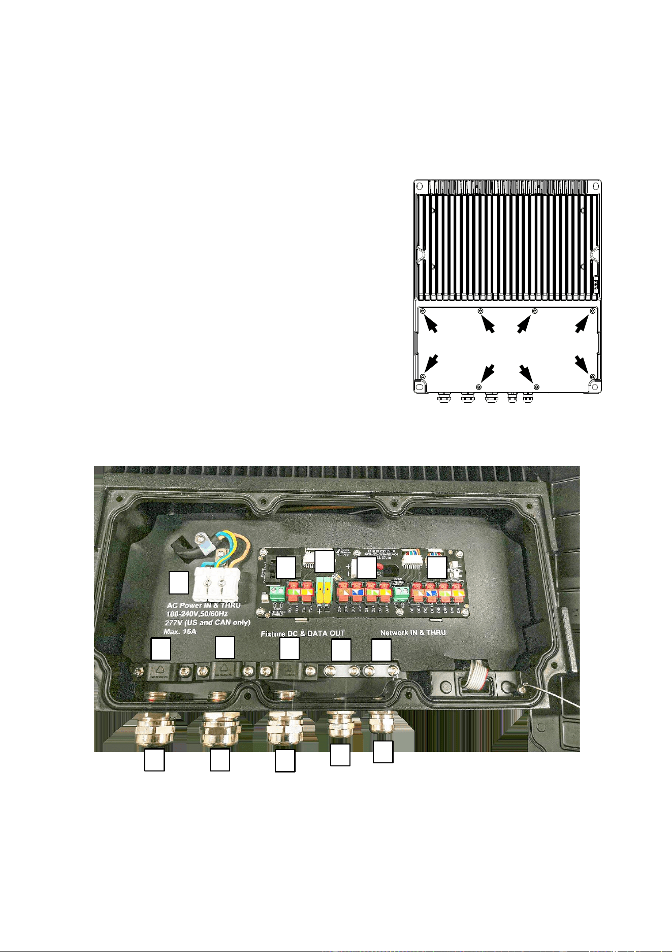
Opening the connections compartment
See illustration on right. For access to the connections
compartment, remove the eight screws (arrowed) from the
connections compartment cover on the top of the device, then
remove the cover.
Connecting and setting up the device
To connect the P3 PowerPort 500 IP Install to AC mains power,
network data and the hybrid link of daisy-chained Martin Creative
LED fixtures, first check that the installation is isolated from
mains power and that power cannot be reapplied, then use the
instructions on the following pages.
Figure 5. P3 PowerPort 500 IP Install connections compartment
E
F
G
H
I
O
Q
K
S
U
J
M
P
R
T

Martin
®
P3 PowerPort 2000 and 500 IP Safety, Installation and User Manual 19
Connecting AC mains power IN
To connect the mains power input cable:
1. Ensure that the installation is isolated from power.
2. The mains power IN cable gland is on the left of
the connections panel (see J in Figure 5). See
Figure 6. The cable entry A is glued into the
housing, so do not try to turn it. Loosen the
compression nut B on the mains power IN cable
gland.
3. Pass the AC mains power input cable through the
cable gland and into the connections box. See
Figure 5. Loosen the cable clamp K on the left in
front of the mains power quick connectors E and
pass the cable through it.
4. Strip enough insulation from the wires in the power
input cable to ensure correct conductivity inside the
quick-connectors without leaving any bare copper visible outside the connectors. Fasten the wires into
the quick-connectors E by pushing down on each connector, inserting the bare end of the wire and
then releasing the connector. Check that the wire is held securely in the connector. Fasten the mains
power wires into the connectors E as follows:
• Live wire to L (Live, brown).
• Neutral wire to N (Neutral, blue).
• Ground/earth wire to (Protective Earth, green/yellow).
5. Tighten the cable clamp K onto the mains power input cable so that it holds the cable firmly.
6. Tighten the compression nut B of the mains power IN cable gland J until the cable is clamped
securely in the cable gland.
Connecting AC mains power THRU
If you are installing a mains power throughput cable to continue mains power to another P3 PowerPort
500 device:
1. The mains THRU cable gland is immediately to the right of the mains IN cable gland on the
connections panel (see M in Figure 5). See Figure 6. The cable entry A is glued into the housing, so
do not try to turn it. Loosen the compression nut B on the mains power THRU cable gland.
2. Pass the AC mains power throughput cable through the cable gland M and into the connections box.
See Figure 5. Loosen the cable clamp O in front of the mains power quick connectors E and pass the
cable through it.
3. Strip enough insulation from the wires in the power throughput cable to ensure correct conductivity
inside the quick-connectors without leaving any bare copper visible outside the connectors. Fasten the
wires into the quick-connectors E by pushing down on each connector, inserting the bare end of the
wire and then releasing the connector. Check that the wire is held securely in the connector. Fasten
the mains power wires into the connectors E as follows:
• Live wire to L (Live, brown).
• Neutral wire to N (Neutral, blue).
• Ground/earth wire to (Protective Earth, green/yellow).
4. Tighten the cable clamp O in front of the mains power quick connectors so that it holds the mains
power throughput cable firmly.
5. Tighten the compression nut B of the mains power THRU cable gland M until the cable is clamped
securely in the cable gland.
If you have finished making connections, check that the connections compartment seal is dry and in
perfect condition, then reinstall the seal and cover on the connections compartment so that the box is
sealed against the entry of water and moisture. Otherwise continue as described below.
Figure 6. Cable gland
B
A
A – Cable entry
B – Compression nut

20 Martin
®
P3 PowerPort 2000 and 500 IP Safety, Installation and User Manual
Connecting the hybrid link to fixtures
To connect the hybrid (combined data and 48 VDC power) cable:
1. If the connections compartment is not already open, open it as described in the previous section.
2. The hybrid OUT cable gland is immediately to the right of the two mains power cable glands (see P in
Figure 5). The cable entry (A in Figure 6) is glued into the housing, so do not try to turn it. Loosen the
hybrid OUT cable gland’s compression nut B.
3. Take the hybrid cable that is connected to the chain of lighting fixtures and pass it through the hybrid
OUT cable gland P and into the connections box. Loosen the hybrid cable clamp Q and pass the
cable through it.
4. Strip enough insulation from the thick red and black DC power wires in the power cable to ensure
correct conductivity inside the quick-connectors without leaving any bare copper visible outside the
connectors. Fasten the DC power wires into the DC power quick-connectors G as follows:
• Red, positive (+) wire to the connector marked 48V+
• Black, negative (-) wire to the connector marked 48V-.
Lift up the orange lever on each quick-connector, put the stripped wire into the connector, then push
the orange lever back down and check that the wire is held securely in the connector.
5. There are four data wires colored orange, orange/white, green and green/white in the hybrid cable. Do
not strip insulation from these wires.
6. Untwist the data wires, lift the levers in the orange hybrid cable data connectors F and slide the wires
into the connectors, respecting the color coding of the wires and the connectors (green to green,
green/white to green/white etc.). Push the levers on the orange connectors all the way down firmly
and check that the wires are held securely.
7. Twist the strands in the data wire shield together to form one twisted wire, loosen one of the screws in
the green screw terminal block at F in Figure 5 and insert this wire into that hole in the terminal block.
Insert the shield from the direction indicated by the arrow next to the terminal. Tighten the screw and
check that the shield is held securely in the terminal block. One hole in this green terminal block can
be left empty.
8. Tighten cable clamp Q onto the hybrid OUT cable until the cable is held tightly.
9. Tighten the compression nut B on the hybrid OUT cable gland P until the cable is held tightly in the
cable gland.
Connecting network data cables
P3 PowerPort devices have two network data ports: port A and port B. It makes no difference which port
you use for data IN from the controller and which port you use for data THRU to other compatible devices.
To connect a network data input cable:
1. If the connections compartment is not already open, open it as described earlier.
2. The data A and B cable glands are immediately to the right of the hybrid cable gland at R and T in
Figure 5. The cable entries (A in Figure 6) are glued into the housing, so do not try to turn them.
Loosen the compression nut B of cable gland R.
3. See Figure 5. Take the data input cable and pass it through the cable gland R and into the
connections box. Loosen the data cable clamp S and pass the cable through it.
4. There are eight data wires colored orange, orange/white, green, green/white, blue, blue/white, brown
and brown/white in the network cable. Do not strip insulation from these wires.
5. Untwist the data wires, lift the levers in the orange network cable data connectors H and slide the
wires into the connectors, respecting the color coding of the wires and the connectors (green to green,
green/white to green/white etc.). Push the levers on the orange connectors all the way down firmly
and check that the wires are held securely.
6. Twist the strands in the data wire shield together to form one twisted wire, loosen one of the screws in
the green screw terminal block between H and I in Figure 5 and insert this wire into that hole in the
terminal block. Insert the shield from the direction indicated by the arrow next to the terminal. Tighten
the screw and check that the shield is held securely in the terminal block.
7. Tighten the cable clamp S onto the data cable until the cable is held tightly.

Martin
®
P3 PowerPort 2000 and 500 IP Safety, Installation and User Manual 21
8. Tighten the compression nut B on the network data cable gland R until the cable is held tightly in the
cable gland.
To connect a network data throughput cable, follow the same procedure as for the network data input
cable (see above), using the remaining data cable gland, cable clamp, quick-connectors and screw
terminal.
Status LED and power mode settings
The two switches located inside the connections compartment let you manage the status LEDs and
Test/Reset button on the front panel (switch marked ‘Front Panel On/Off’) and manage the power setting
of connected fixtures (switch marked ‘Power Control/Full/Half’). See ‘Switches’ on page 10 for more
details.
Closing the connections compartment
When you have finished making connections and/or setting the two switches (see above), check that the
connections compartment seal is clean, dry and in perfect condition, then reinstall the cover on the
connections compartment to protect against the entry of water, moisture and dirt.
Operating
When power is applied to the power input cable, the device carries out a short boot procedure and then
becomes operational. There is no power on/off switch.
Status LEDs and Test/Reset button
You can monitor operation via the status LEDs on the front panel if they are activated using the switch
inside the connections compartment.
You can send test patterns to connected Martin Creative LED fixtures and reboot the device using the
Test/Reset button on the front of the device.
See ‘Status LEDs and Test/Reset button’ on page 22 for details of these two features.

22 Martin
®
P3 PowerPort 2000 and 500 IP Safety, Installation and User Manual
Status LEDs and Test/Reset button
Status information
P3 PowerPort devices give status information via LEDs on their front panels. A key to the status
information given by the LEDs is printed on the device and given below.
For each output:
• The Data LED lights when data is being transmitted at that output.
• The Power LED lights when 48 VDC power is present at that output.
• NET1 and NET2 LEDs light to indicate traffic at the corresponding network data port.
• The LED gives the information in the table below:
Color
Output
Indication
Suggested action
Blue
Constant
Busy (e.g. booting up or writing to
flash memory).
Wait a moment for normal
operation to be resumed.
Green
Constant
P3 protocol detected.
Magenta
Constant
Art-Net or sACN detected.
Red
Flashing
No control source detected (no
protocol detected on Ethernet).
Connect a P3 System Controller,
Art-Net controller or sACN
controller to the network.
Yellow
Constant
Overtemperature.
Allow the device to cool. Clean
the device and improve
ventilation. Press Test/Reset
button to restore functionality.
Red
Constant
Error. The P3 PowerPort has
encountered a fatal error and
cannot run.
Perform a factory reboot. If the
problem persists, carry out a
firmware upload.
Fast RGB
Cycling
Test pattern being sent to
connected products.
Test/Reset button functions
P3 PowerPort devices have test sequences stored in internal memory that you can call up using the
Test/Reset button. The test sequences let you check that the connected creative LED products are set up
correctly without the need for a controller. Note that test patterns can also be called up on P3 system
controllers and on any individual system components that have a test/control button.
The Test/Reset button also lets you reboot the device and restore its factory default firmware if you
suspect that the firmware has been corrupted.
If an output on a P3 PowerPort has been disabled because of an overload or short circuit, pressing the
Test/Reset button will re-enable the output.
The functions of the P3 PowerPort’s single Test/Reset button are printed on the device and given below:
Button action
Function
Repeated short press
Display the following test patterns on all Martin Creative LED
display products that are correctly connected (one short press
scrolls to next pattern): Calibrated mixed White → Full Red → Full
Green → Full Blue → Full White
Press and hold until status
LED lights blue
Reboot the P3 PowerPort.
Press and hold until status
LED lights white
Return the P3 PowerPort to its default factory firmware.

Martin
®
P3 PowerPort 2000 and 500 IP Safety, Installation and User Manual 23
Service and maintenance
Warning! Read “Safety Information” on page 4 before carrying out service or maintenance
work.
Disconnect all devices from AC mains power before servicing.
Refer any service operation not described in this user manual to Martin Service or an
authorized Martin service agent.
Important! Excessive dirt buildup causes overheating and will damage the product. Damage
caused by inadequate cleaning is not covered by the product warranty.
The user will need to clean the device periodically. The user can also install firmware in P3 PowerPort
2000 and 500 devices. All other service operations must be carried out by Martin Professional or an
authorized Martin service agent.
Installation, on-site service and maintenance can be provided worldwide by the Martin Professional Global
Service organization and its approved agents, giving owners access to Martin’s expertise and product
knowledge in a partnership that will ensure the highest level of performance throughout the product’s
lifetime. Please contact your Martin supplier for details.
Cleaning
Cleaning schedules vary greatly depending on the operating environment. It is therefore impossible to
specify precise cleaning intervals for devices in the P3 PowerPort family. Cooling fans suck in airborne
dust and smoke particles, and in extreme cases, the product and its air filters may require cleaning after
surprisingly few hours of operation. Environmental factors that may result in a need for frequent cleaning
include:
• Use of smoke or fog machines.
• High airflow rates (near air conditioning vents, for example).
• Presence of cigarette smoke.
• Airborne dust (from stage effects, building structures and fittings or the natural environment in outdoor
locations, for example).
If one or more of these factors is present, inspect products within their first 25 hours of operation to see
whether cleaning is necessary. Check again at frequent intervals. This procedure will allow you to assess
cleaning requirements in your particular situation. If in doubt, consult your Martin dealer about a suitable
maintenance schedule.
To clean a product in the P3 PowerPort family:
1. Shut down power to the device and allow it to cool for at least 15 minutes.
2. Use a vacuum cleaner or low-pressure compressed air to gently remove dust and loose particles from
the outside of the device, paying special attention to fan grills and air vents. Take care not to direct the
vacuum or air jet at cooling fan blades because this can spin the fan too fast and cause damage that
is not covered by the product warranty. You can avoid this problem by holding fans still with a
screwdriver while you are working.
3. Wipe the outside of the device with a cloth lightly moistened in a mild detergent solution. Do not
splash with water. You can rinse an IP66-rated device with water, but do not direct a high-pressure
water jet at the device. Do not use any product that contains abrasives or solvents.
4. Dry the device with a soft cloth before reapplying power.
Pressure equalization valves
Each P3 PowerPort 500 IP device has a pressure equalization valve (see illustrations for each device
earlier in this manual). Check this valve visually from time to time. If it appears to be dirty, consult Martin
Service for possible replacement.

24 Martin
®
P3 PowerPort 2000 and 500 IP Safety, Installation and User Manual
Installing firmware
It may be necessary to upload new firmware to a P3 PowerPort device if it appears to have a firmware -
related fault or if you want to update to a newer firmware version.
You can check the P3 PowerPort’s currently installed firmware version using an RDM tool such as Martin
Companion or a Martin P3 System Controller.
Firmware updates are available from the Martin website and can be downloaded automatically from within
the Martin Companion software suite on a PC connected to the Internet. You can install firmware updates
using a P3 system controller or Martin Companion connected to the devices.
Important! Do not switch the P3 PowerPort off or disconnect the source of the firmware during an update,
or the firmware will be corrupted.
Installing using a PC running Martin Companion
The following are required in order to install firmware using a PC:
• A Windows PC running the latest version of the Martin Companion application (available for download
free of charge from the Martin website at www.martin.com).
• The P3 PowerPort firmware file (the Martin Companion application will download this file automatically
when you run Martin Companion on a PC with an Internet connection).
• A network cable with RJ45 connectors to connect the PC running Martin Companion to the P3
PowerPort(s).
To install the P3 PowerPort firmware:
1. Connect your PC to the Internet and launch the Martin Companion application. The application will
automatically download the latest device firmware from the Martin cloud.
2. Read the firmware release notes carefully to check for any instructions or warnings.
3. Connect the PC running Martin Companion to the P3 PowerPort(s) using a standard network cable
with RJ45 connectors:
• You can connect this cable to the Ethernet ports on the P3 PowerPort 2000 and P3 PowerPort
500 IP Rental devices directly or connect it to the control data link at some convenient point
upstream of these devices.
• Since the P3 PowerPort 500 IP Install does not have Ethernet ports, it is easiest if you connect
your PC to the control data link at a convenient point upstream of the device. For workshop use,
you can connect a network cable temporarily to the terminals inside the connections compartment
following the instructions in ‘Connecting network data cables’ on page 20.
4. Carry out a firmware upload from within the Martin Companion application (see the application’s help
files if necessary). Do not disconnect the Martin Companion network cable until the upload is
complete.
Installing from a P3 System Controller
To install firmware in the P3 PowerPort from a Martin P3 System Controller, you must first download the
latest P3 PowerPort firmware file automatically from the Martin cloud using the Martin Companion
application running on a PC connected to the Internet. You must then import the firmware into the P3
System Controller. Once imported, you can use the P3 System Controller to upload the firmware to all the
P3 PowerPort devices on the network that are powered on.
When you import new firmware into a P3 System Controller, it will automatically recognize old firmware in
P3 PowerPort devices and suggest a firmware update.
When carrying out firmware updates, the P3 System Controller must be connected to devices via Ethernet
cable as normal. Updating the firmware is a fairly intuitive process using the commands available in the
controller interface. Any P3 PowerPort devices that are powered on will recognize that the P3 System
Controller is offering a firmware update and prepare to receive the firmware.

Martin
®
P3 PowerPort 2000 and 500 IP Safety, Installation and User Manual 25
Troubleshooting
Problem
Probable cause(s)
Remedy
Status LED lights constant
red
Error has occurred
Check that system is correctly connected, set
up and running.
Hold TEST/RESET button pressed in until it
turns blue, then release. This will reboot the
P3 PowerPort device.
Restart P3 system controller.
Product is completely dead
No power to product
Check that power is switched on and cables
are plugged in.
Fuse blown
Disconnect from power. Check – and if
necessary replace – fuses following the
instructions in this user manual.
If a fuse blows repeatedly, disconnect from
power and contact Martin Service or an
authorized Martin service partner for
assistance.
Internal fault
Disconnect from power. Do not try to repair
the device yourself. Contact Martin Service or
an authorized Martin service partner for
assistance.
Devices connected to one of
the hybrid outputs are
completely dead
Controller incorrectly setup
Check controller settings and rectify any
problems.
Poor connections
Check connections and rectify any faults.
Circuit breaker has tripped (if this
happens, the Power status LED for that
output will not light)
Reset circuit breaker by sending command
from controller or pressing multi-function
button on front panel.
If circuit breaker trips again:
• Output may be overloaded. See user
manuals of all connected devices. Check
that devices are connected as specified and
that the number of connected devices does
not exceed the maximum permitted limit.
• Output may be short-circuited. Check wiring
and rectify any faults.
If a circuit breaker trips repeatedly and you
cannot find the cause, disconnect from power
and contact Martin Service or an authorized
Martin service partner for assistance.
Internal fault
Disconnect from power. Do not try to repair
the device yourself. Contact Martin Service or
an authorized Martin service partner for
assistance.
Creative LED products do
not behave as intended
Bad DC power transmission
Inspect connections and cables. Correct poor
connections. Repair or replace damaged
cables.
Bad data transmission
Inspect connections and cables. Correct poor
connections. Repair or replace damaged
cables.
Incorrect device addressing
Check device addresses and settings at
controller.
Product in installation is defective and is
disturbing data transmission
Substitute known good products one at a time
until normal operation is regained. Have faulty
product serviced by qualified technician.
Table 4: Troubleshooting

26 Martin
®
P3 PowerPort 2000 and 500 IP Safety, Installation and User Manual
FCC Compliance
This equipment has been tested and found to comply with the limits for a Class B digital device, pursuant
to part 15 of the FCC Rules. These limits are designed to provide reasonable protection against harmful
interference in a residential installation. This equipment generates, uses and can radiate radio frequency
energy and, if not installed and used in accordance with the instructions, may cause harmful interference
to radio communications. However, there is no guarantee that interference will not occur in a particular
installation. If this equipment does cause harmful interference to radio or television reception, which can
be determined by turning the equipment off and on, the user is encouraged to try to correct the
interference by one or more of the following measures:
• Reorient or relocate the receiving antenna.
• Increase the separation between the equipment and receiver.
• Connect the equipment into an outlet on a circuit different from that to which the receiver is connected.
• Consult the dealer or an experienced radio/TV technician for help.
FCC Supplier’s Declaration of Conformity
This device complies with Part 15 of the FCC Rules. Operation is subject to the following two conditions:
(1) This device may not
cause harmful interference, and (2) this device must accept any interference
received, including interference that may cause
undesired operation.
Canadian Interference-Causing Equipment Regulations
This Class B digital apparatus meets all requirements of the Canadian Interference-Causing Equipment
Regulations.
Règlement sur le Matériel Brouilleur du Canada
Cet appareil numérique de la classe B respecte toutes les exigences du Règlement sur le Matériel
Brouilleur du Canada.
EU Declaration of Conformity
An EU Declaration of Conformity covering this product is available for download from the product’s area of
the Martin website at www.martin.com.
Disposing of the product
Martin products are supplied in compliance with Directive 2012/19/EC of the
European Parliament and of the Council of the European Union on WEEE (Waste
Electrical and Electronic Equipment), where applicable.
Help preserve the environment! Ensure that this product is recycled at the end of its
life. Your supplier can give details of local arrangements for the disposal of Martin
products