VDO Atomic Dot
User Guide

Table of contents
Dimensions ...................................................................................................3
Safety information.........................................................................................8
Précautions d'emploi...................................................................................10
Sicherheitshinweise ....................................................................................13
Introduction .................................................................................................17
Before using the product for the first time..........................................................17
Fixture overview..........................................................................................18
Physical installation.....................................................................................19
Fixture location..................................................................................................19
Ways of mounting the fixture.............................................................................19
Mounting the fixture on a truss using the hanging bracket ................................20
Mounting 2 or 4 fixtures on a truss using the double width hanging bracket .....21
Mounting the fixture on a truss using direct clamp ............................................22
Interlocking multiple fixtures ..............................................................................23
Installing optical accessories.............................................................................25
Safety bonds .....................................................................................................26
AC power and data connection...................................................................27
Safety limits for connecting devices ..................................................................27
AC power connection to Junction Box or Break-In cable...................................27
Data connection to Junction Box or Break-In cable...........................................28
PDE connections between fixtures....................................................................30
System Setup..............................................................................................31
Setting options by RDM.....................................................................................31
Scanning for RDM devices on the data link.......................................................31
Getting status and setting options by RDM .......................................................31
Martin Companion and RDM.............................................................................31
RDM..................................................................................................................32
Using the VDO Atomic Dot .........................................................................34
Thermal regulation ............................................................................................34
Video display using P3......................................................................................34
DMX control ......................................................................................................34
LED PWM frequency control .............................................................................34
Status LED........................................................................................................35
Pushbutton functions.........................................................................................35
Maintenance ...............................................................................................37
Cleaning............................................................................................................37
LED performance ..............................................................................................37
Installing new software......................................................................................37
DMX protocol ..............................................................................................38
DMX mode 1 channel........................................................................................38
DMX mode 3 channel........................................................................................38
DMX mode 4 channel........................................................................................39
DMX mode Basic ..............................................................................................39
DMX mode Extended ........................................................................................42
FX Table............................................................................................................49
Troubleshooting ..........................................................................................52
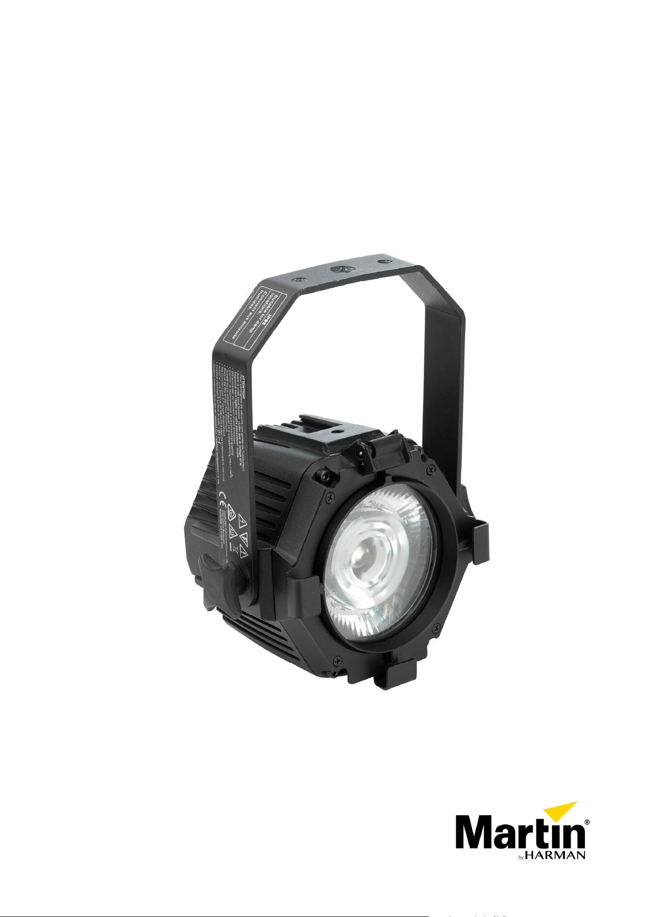
Dimensions
Fixture dimensions
175.2
146
241.6
All dimensions are given in millimeters.
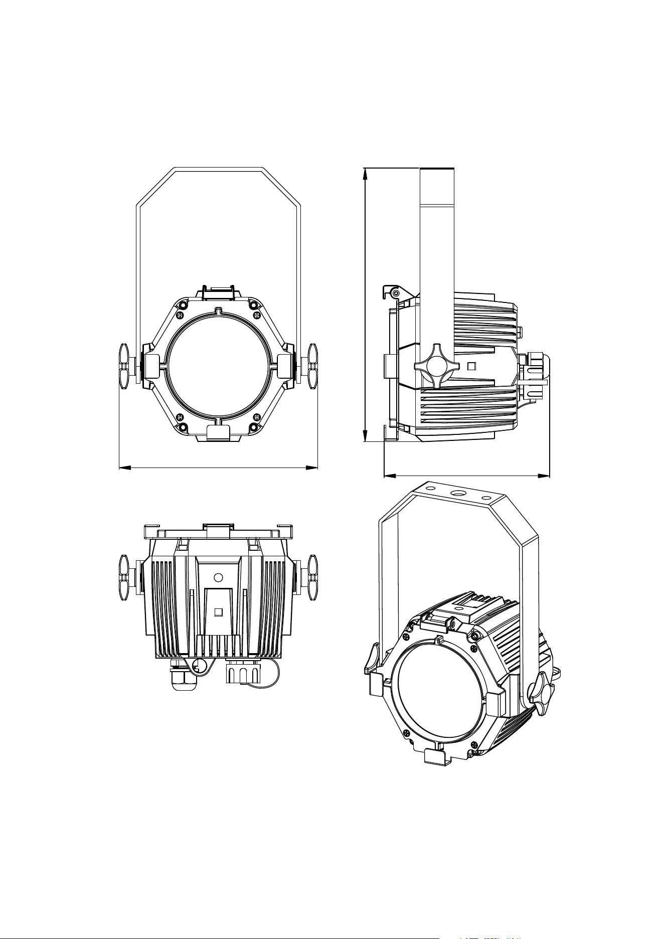
Coupler (for interlocking two fixtures)
21
41
49
44
37
33
Half Coupler (for attaching to truss)
33
50.8
41
49
18
90
140
85
All dimensions are given in millimeters.
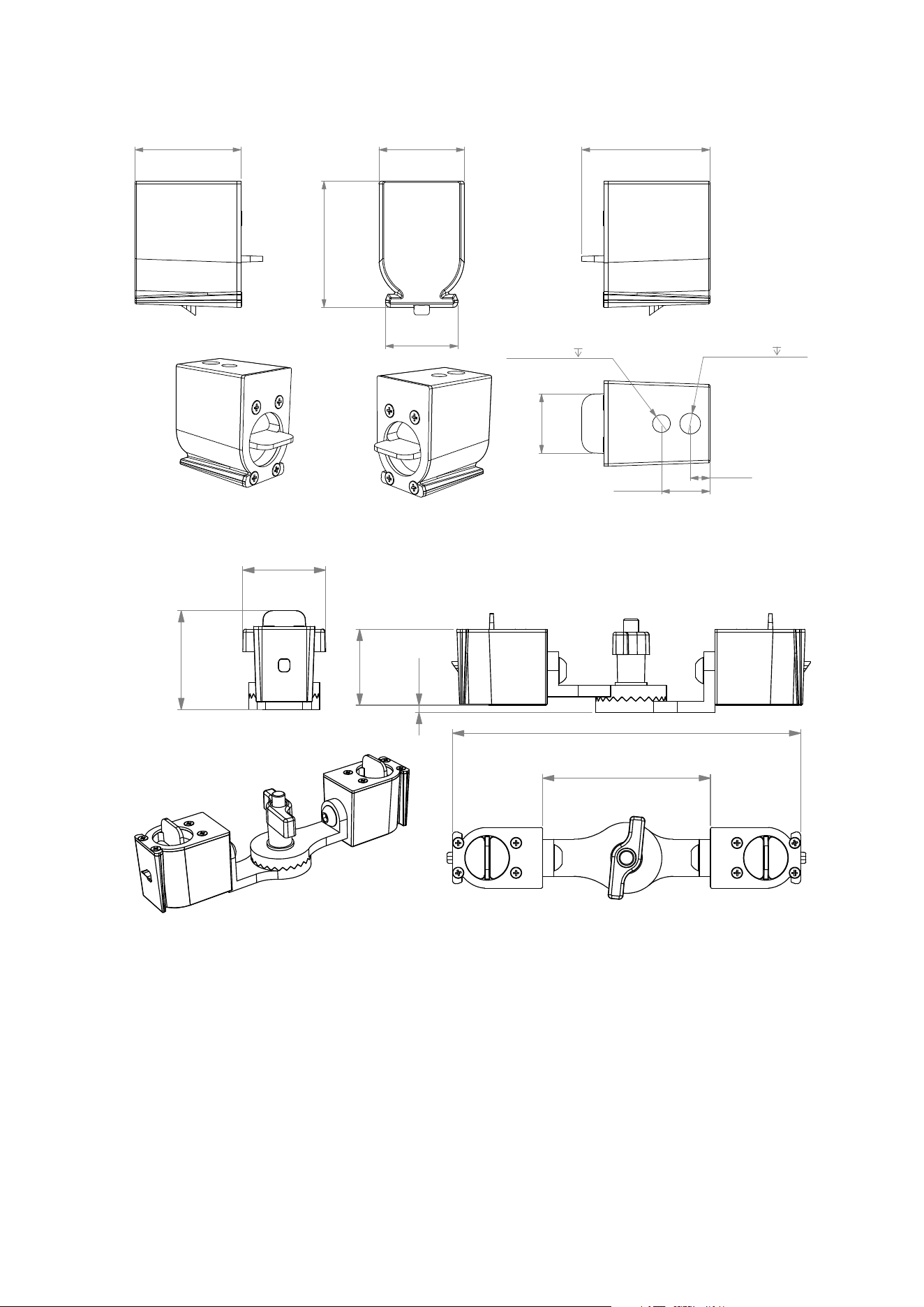
Interlock Adapter (for attaching to microphone stand)
41 33
28
18.5
15.0M8x1.25-6H
3/8-16UNC
15.0
7.5
49
48
23
Pivot coupler (for interlocking two fixtures at an angle)
44
90
187
53
41
4
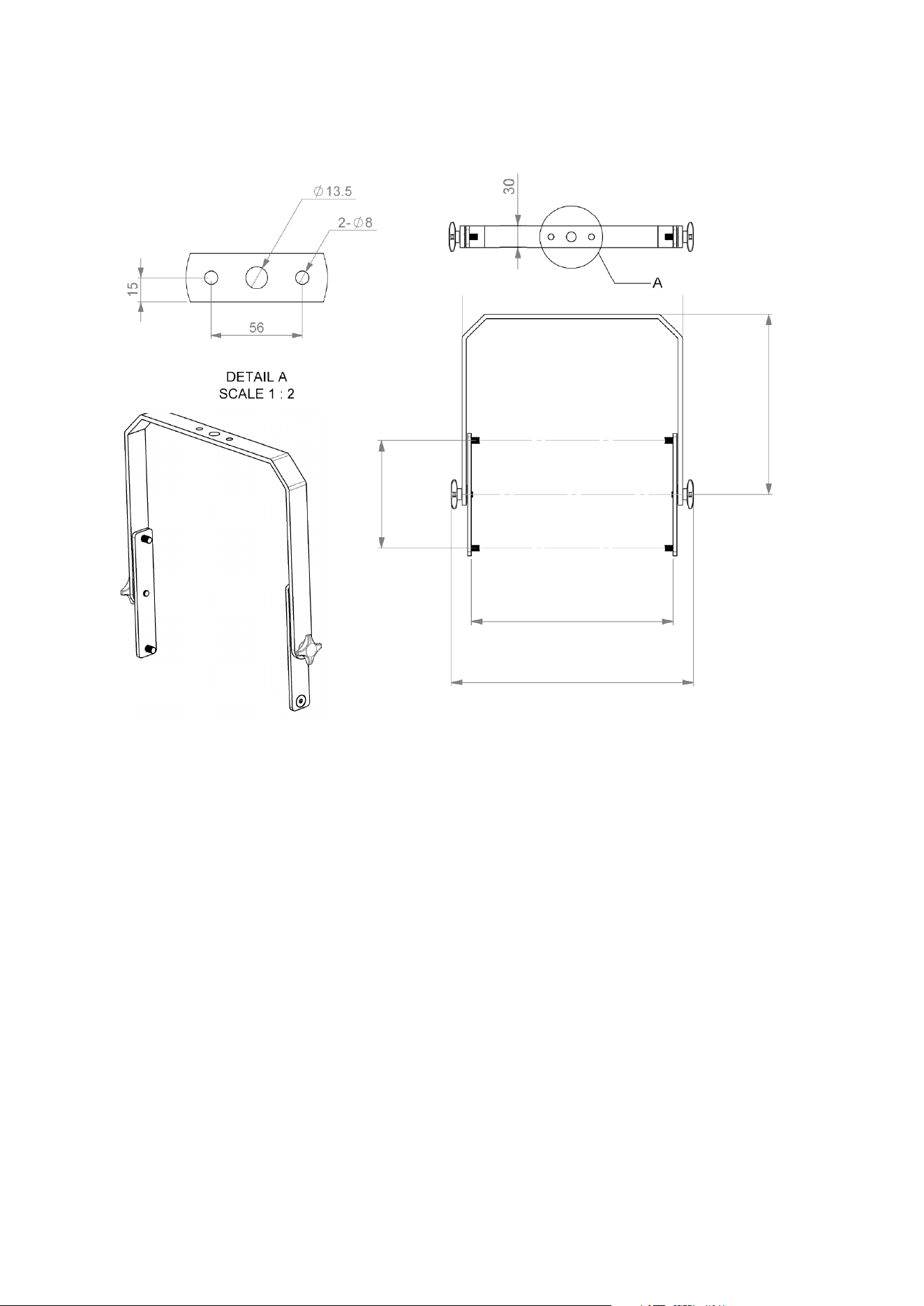
Double Width Bracket (for creating 2-lite and 4-lite fixtures)
338
282
308
150
252
All dimensions are given in millimeters.
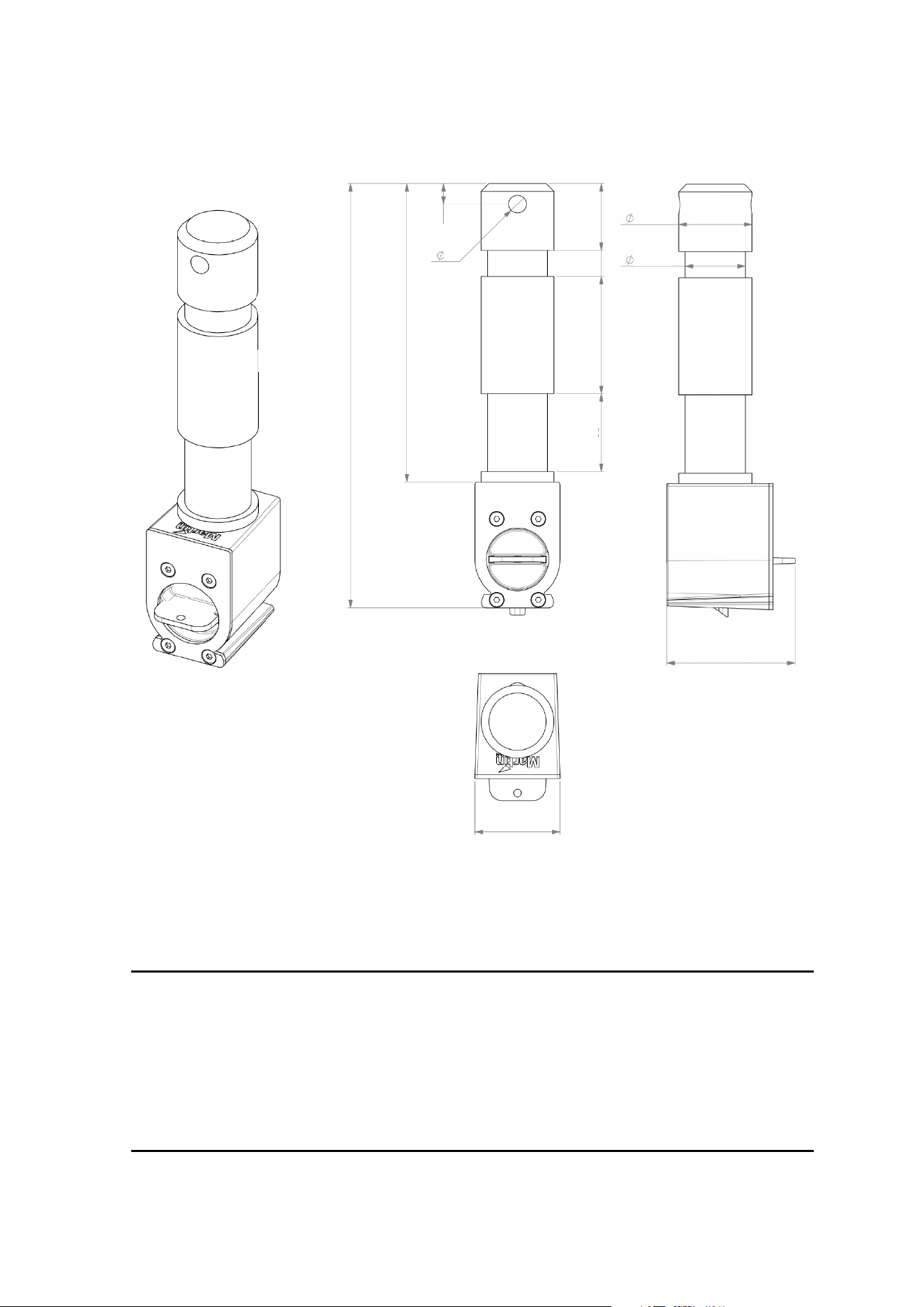
Spigot Adapter (for mounting on standard spigot accessories)
49
33
7
163
115
26
45
30
10
8
28
23
© 2012-2023 HARMAN PROFESSIONAL DENMARK ApS. All rights reserved. Features, specifications and appearance
are subject to change without notice. HARMAN PROFESSIONAL DENMARK ApS and all affiliated companies disclaim
liability for any injury, damage, direct or indirect loss, consequential or economic loss or any other loss occasioned by the
use of, inability to use or reliance on the information contained in this document. Martin is a registered trademark of
HARMAN PROFESSIONAL DENMARK ApS registered in the United States and/or other countries.
HARMAN PROFESSIONAL DENMARK ApS • Olof Palmes Alle 44 • 8200 Aarhus N • Denmark
HARMAN PROFESSIONAL SOLUTIONS U.S. • 8500 Balboa Blvd. • Northridge • CA 91329 • USA
www.martin.com
VDO Atomic Dot User Guide Revision D
All dimensions are given in millimeters.
8 Martin VDO Atomic Dot user guide
Safety information
WARNING!
Read the safety precautions in this manual before installing, operating or
servicing this product.
The following symbols are used to identify important safety information on the product and in this
manual:
Warning!
Safety
hazard. Risk
of severe
injury or
death.
Warning!
Powerful
light
emission.
Risk of eye
injury.
Warning!
See user
manual for
important
safety
information.
Warning!
Hazardous
voltage. Risk
of lethal or
severe
electric
shock.
Warning!
Fire hazard.
Warning!
Hot surfaces.
VDO Atomic Dot CLD only: Warning! Risk Group 2 product according to EN 62471
and IEC/TR 62778. Possibly hazardous radiation emitted from this product. May be
harmful to the eyes. Do not stare at operating lamp and do not view the light output
with optical instruments or any device that may concentrate the beam.
This lighting fixture is for professional use only and must be installed by a qualified
technician. It is not for household use. It presents risks of severe injury or death
due to fire hazards, electric shock and falls. It can create a fire hazard or a risk of
eye injury if the safety precautions below are not followed.
Install, operate and service Martin® products only as directed in their user
manuals, or you may create a safety hazard or cause damage that is not covered
by product warranties. Follow the safety precautions listed below and observe all
warnings in this manual and printed on the product. Keep this user manual for
future use.
For the latest user documentation and other information about this and all Martin®
products, please visit the Martin® website at http://www.martin.com
If you have a
ny questions about how to install, operate or service the fixture safely,
please contact your Martin® distributor (see www.martin.com/distributors for
details) or in the USA on 1-844-776-4899.
Respect all locally applicable laws, codes and regulations when installing,
operating or servicing the fixture.
Protection from electric shock
Ensure that the fixture is electrically connected to ground (earth).
Disconnect the fixture from AC power when not in use.
Do not open the fixture or remove any cover. Refer any service operation not
described in this manual to an authorized Martin Service partner.
Shut down power to the entire installation at the main power distribution board and
lock out power before carrying out any installation or maintenance work.
Martin VDO Atomic Dot user guide 9
Use only a source of AC power that complies with local building and electrical
codes and has both overload and ground-fault (earth-fault) protection.
Isolate the fixture from power immediately if any seal, cover, cable, or other
component is damaged, defective, deformed or showing signs of overheating. Do
not reapply power until repairs have been completed
Before using the fixture, check that all power distribution equipment and cables are
in perfect condition and are of suitable type for the location (including water,
pollution, temperature and UV resistance).
Do not immerse the fixture in water or any other fluid, or install it in a location
where flooding may occur.
The light source contained in this luminaire shall only be replaced by the
manufacturer or their service agent or a similar qualified person.
When connecting multiple fixtures in a daisy chain, observe the safety limits in
section “Safety limits for connecting devices” on page 27.
Protection from burns and fire
Do not operate the fixture if the ambient temperature (Ta) exceeds 40° C (104° F).
The surface of the fixture can reach up to 55° C (131° F) if the fixture is operated at
the maximum permitted ambient temperature. Allow the fixture to cool for at least 5
minutes before handling.
Install the fixture on a non-combustible surface (brick, concrete, plaster etc.) only.
Do not aim the fixture towards combustible materials (fabric, wood, paper etc.) that
are within 50 cm (19 in.) of the fixture.
Keep the fixture well away from flammable materials (volatile liquids etc.).
Ensure that there is free and unobstructed airflow around the fixture.
Allow at least 0.1 m (4 in.) free space around the fixture.
Do not attempt to bypass thermostatic switches or fuses.
Do not modify the fixture in any way not described in this manual or install other
than genuine Martin® parts. Do not stick filters, masks or other materials onto any
lens or other optical component. Use only accessories approved by Martin® to
modify the light beam.
Protection from eye injury
VDO Atomic Dot CLD only: Warning! Risk Group 2 product according to EN 62471
and IEC/TR 62778.
Do not look directly into the product’s light output.
Do not look at operating lamp. Eye injury may result.
Do not look at the light output with magnifiers, telescopes, binoculars or similar
optical instruments that may concentrate the light output.
Ensure that persons are not looking directly into the front of the fixture when the
product lights up suddenly. This can happen when power is applied, when the
product receives a DMX signal, or when certain control menu items are selected.
To minimize the risk of eye irritation or injury, disconnect the fixture from power at
all times when the fixture is not in use and provide well-lit conditions to reduce the
pupil diameter of anyone working on or near the fixture.
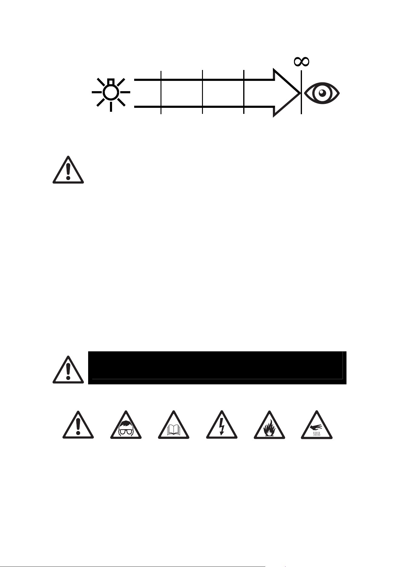
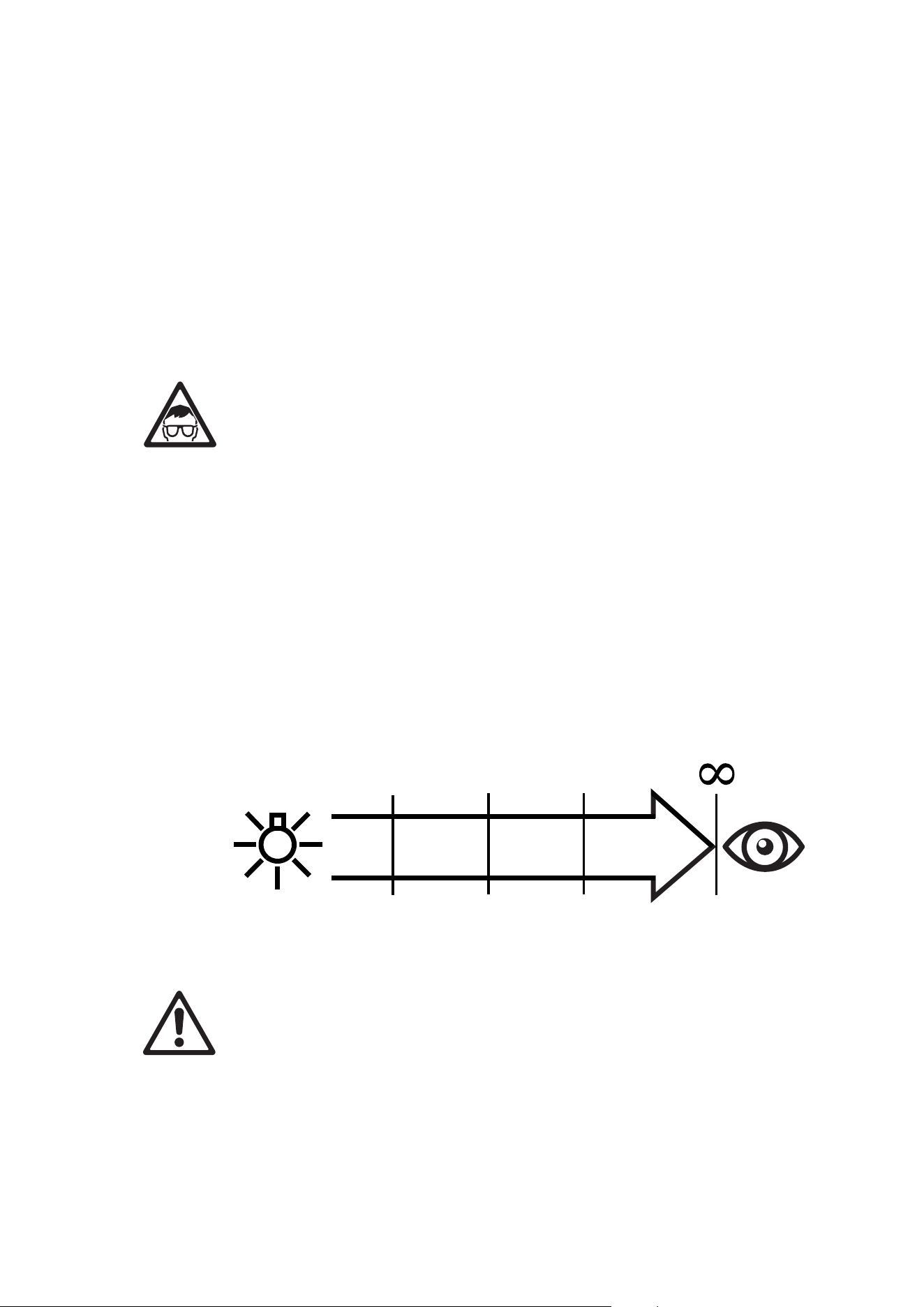
The VDO Atomic Dot CLD fixture fixtures fall into the following risk groups
according to EN 62471 and IEC/TR 62778 at the distances indicated below.
10 Martin VDO Atomic Dot user guide
RISK GROUP
DO NOT
USE
2
RISK GROUP
1
1.0 m
0.2 m
(39.4 in.)
(7.9 in.)
9.6 m
(31.5 ft.)
RISK GROUP
EXEMPT
The luminaire should be positioned so that prolonged staring into the luminaire at a
distance closer than 1 m is not expected.
Protection from injury
Fasten the fixture securely to a fixed surface or structure when in use. The fixture
is not portable when installed.
Ensure that all supporting structures, surfaces, fasteners and lifting equipment can
bear the weight of all the devices they are intended to support plus an adequate
safety margin, and that they conform to local building and safety regulations.
Ensure that any accessory such as gel frames, gobo holders are securely
fastened.
Block access below the work area and work from a stable platform whenever
installing, setting, adjusting, or cleaning the fixture.
Do not operate the fixture with missing or damaged covers, shields or any optical
component.
If an operating problem occurs, stop using the fixture immediately and disconnect it
from power. Do not attempt to use a fixture that is obviously damaged.
Précautions d'emploi
ATTENTION !
Lisez les précautions d'emploi listées dans ce manuel avant
d'installer,d'utiliser ou de faire la maintenance de l'appareil.
Les symboles ci-dessous sont utilisés pour identifier les informations de sécurité importantesl:
Attention !
Risque
important.
Risque de
blessure
sévère voire
mortelle.
Attention !
Emission
puissante de
lumière.
Risque de
lésion
oculaire.
Attention !
Reportez-
vous au
manuel
d'utilisation
pour les
informations
de sécurité.
Attention !
Tensions
dangereuses.
Risque de
blessure
sévère voire
mortelle par
électrisation.
Attention !
Risque
d'incendie.
Attention !
Surfaces
chaudes.

Martin VDO Atomic Dot user guide 11
VDO Atomic Dot CLD seulement:Attention ! Groupe de risques 2 selon EN 62471
et IEC/TR 62778. Cet appareil émet des radiations potentiellement dangereuses.
Ne fixez pas le regard sur la source de lumière allumée et ne regardez pas dans le
faisceau avec un instrument optique ou tout appareil qui pourrait concentrer la
lumière.
Ce luminaire est réservé à un usage professionnel et doit être installé par un
technicien qualifié uniquement. Il présente des risques de blessures sévères voire
mortelles par brûlure ou incendie, électrisation et chute. Il peut créer un risque
important d'incendie ou de lésions oculaires si les précautions d'emploi ci-dessous
ne sont pas respectées.
Veuillez uniquement installer, utiliser ou réaliser la maintenance des produits
Martin® en respectant les directives de leur manuel d'utilisation au risque de créer
un risque pour la sécurité ou de causer des dommages qui ne seraient pas
couverts par la garantie du produit. Suivez les précautions d'emploi listées
cidessous et respectez toutes les mises en garde continues dans ce manuel et
imprimées sur le produit. Gardez ce mode d'emploi pour un usage ultérieur.
Pour obtenir les dernières mises à jour de ce document ou de toute information sur
ce produit et le reste de la gamme Martin®, consultez le site web de Martin® :
http://www.martin.com
Pour toute question sur l'installation, l'utilisation ou l'entretien de cet appareil en
toute sécurité, contactez votre distributeur Martin® (voir
www.martin.com/distributors pour plus de détail) ou bien, pour les USA, appelez le
1-844-776-4899.
Respectez toutes les règlementations, codes et lois locales applicables lors de
l'installation, de l'utilisation et de la maintenance de cet appareil.
Protection contre les risques électriques
Assurez-vous que l'appareil est correctement relié à la terre électrique.
Déconnectez l'appareil du secteur lorsqu'il n'est pas en service. N'ouvrez pas
l'appareil et ne déposez aucun capot. Référez toute opération non décrite ici à un
service technique agréé par Martin.
Coupez l'alimentation de l'installation au tableau de distribution et consignez-la
avant de commencer l'installation ou la maintenance.
N'utilisez qu'une source d'alimentation AC compatible avec les codes locaux de la
construction et de l'électricité et protégée contre les surintensités et les défauts
différentiels.
Isolez immédiatement l'appareil du secteur si un joint, un capot, un câble ou tout
autre composant est endommagé, défectueux, déformé ou montre des signes de
surchauffe. Ne remettez pas le système sous tension tant que les réparations n'ont
pas été effectuées.
Avant d'utiliser l'appareil, vérifiez que tous les équipements de distribution
d'énergie et tous les câbles sont en parfaite condition et sont adaptés au lieu
d'installation (incluant humidité, pollution, température et résistance aux UV).
N'immergez pas l'appareil dans l'eau ou dans tout autre fluide. Ne l'installez pas
dans une zone inondable.
La source de lumière de cet appareil ne peut être remplacée que par le fabricant
ou ses services techniques ou un technicien qualifié.
Lorsque vous connectez plusieurs appareils en cascade, respectez les limitations
indiquées dans la section “Limites de sécurité pour la connexion des appareils” en
page 27.
12 Martin VDO Atomic Dot user guide
Protection contre les incendies et les brûlures
N'utilisez pas l'appareil si la température ambiante (Ta) dépasse 40° C (104° F).
La surface de l'appareil peut atteindre 55° C (131° F) si l'appareil est utilisé à la
température ambiante maximale permise. Laissez l'appareil refroidir au moins 5
minutes avant de le manipuler.
Installez l'appareil sur une surface non combustible (brique, béton, plâtre etc.)
uniquement.
Ne braquez pas l'appareil vers des matériaux combustibles (papier, bois, tissu etc.)
s'ils sont situés à moins de 50 cm (19 in.) de l'appareil.
Maintenez l'appareil éloigné de tout matériau inflammable (liquides volatiles etc.).
Assurez-vous que l'air circule librement autour de l'appareil.
Laissez au moins 0,1 m (4 in.) d'espace libre autour de l'appareil.
N'essayez pas de contourner l'action des organes de protection tels que fusibles
ou interrupteurs thermostatiques.
Ne modifiez pas l'appareil autrement que selon les directives contenues dans ce
manuel et n'installez que des pièces détachées d'origine Martin®. Ne collez pas de
filtre, de masque ou tout autre matériau sur les lentilles et les composants
optiques. Utilisez uniquement des accessoires homologués par Martin® pour
modifier le faisceau de l'appareil.
Protection contre les lésions oculaires
VDO Atomic Dot CLD seulement: Attention ! Groupe de risques 2 selon EN 62471
et IEC/TR 62778.
Ne regardez pas directement dans le faisceau de l'appareil.
Ne regardez pas la source de lumière lorsqu'elle est allumée. Risque de lésion
oculaire.
Ne regardez pas la lumière produite par l'appareil avec un instrument optique qui
pourrait concentrer la lumière tel qu'une loupe, un microscope, un télescope etc.
Assurez-vous que personne ne regarde l'appareil lorsqu'il s'allume brusquement.
Ceci peut se produire à la mise sous tension, à réception d'un signal DMX ou lors
de la manipulation de certaines rubriques du panneau de contrôle.
Pour minimiser le risque d'irritation de l'oeil ou de lésions oculaires, déconnectez
toujours le produit du secteur lorsqu'il n'est pas utilisé et maintenez un éclairement
minimal suffisant pour réduire le diamètre des pupilles de toute personne travaillant
à proximité ou sur l'appareil lui-même.
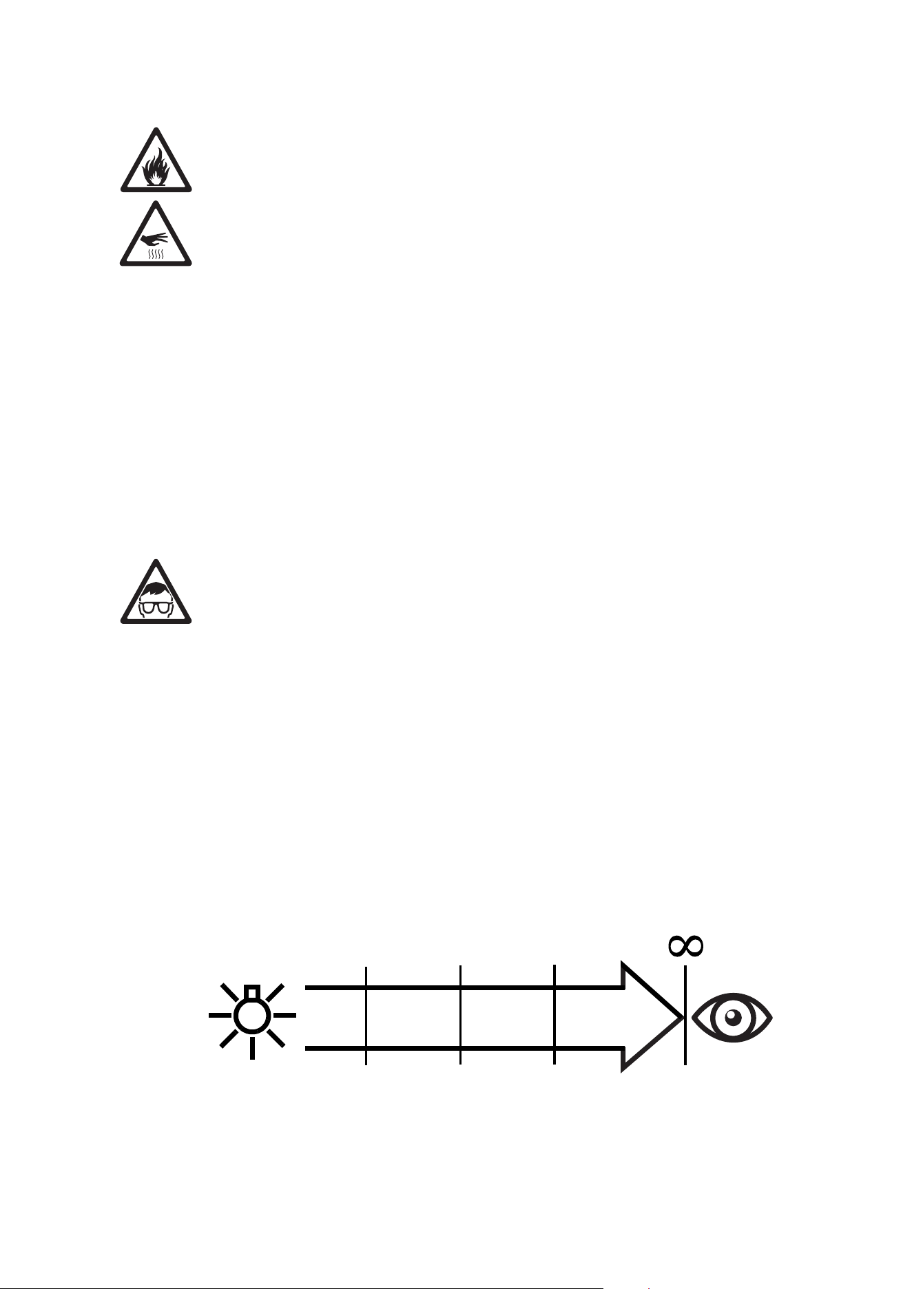
Le VDO Atomic Dot CLD tombe dans les groupes de risque ci-dessous selon EN
62471 et IEC/TR 62778 en fonction de sa distance à l'observateur.
RISK GROUP
DO NOT
USE
2
RISK GROUP
1
1.0 m
0.2 m
(39.4 in.)
(7.9 in.)
9.6 m
(31.5 ft.)
RISK GROUP
EXEMPT
L'appareil doit être installé de façon à éviter toute observation prolongée à une
distance inférieure à 1 m.
Martin VDO Atomic Dot user guide 13
Protection contre les blessures
Fixez l'appareil fermement à une surface fixe lors de son utilisation. L'appareil n'est
pas transportable pendant son fonctionnement.
Assurez-vous que toutes les structures et surfaces porteuses et que tous les
accessoires de fixation et de levage supportent le poids de tous les appareils qu'ils
reçoivent avec une conséquente marge de sécurité et qu'ils sont conformes aux
codes et aux règles de sécurité locales et de la construction.
Assurez-vous que tous les accessoires tels que porte-filtres, porte-gobos … sont
fermement fixés.
Interdisez l'accès sous la zone de travail et travaillez sur une plateforme stable lors
de l'installation, des réglages, du paramétrage ou du nettoyage de l'appareil.
N'utilisez pas l'appareil s'il manque des capots, des protections ou des composants
optiques ou s'ils sont endommagés.
En cas de problème de fonctionnement, arrêtez immédiatement l'appareil et
déconnectez-le du secteur. N'essayez pas d'utiliser un appareil visiblement
endommagé.
Sicherheitshinweise
WARNUNG!
Lesen Sie die Sicherheitshinweise, bevor Sie das Produkt installieren, in
Betrieb nehmen, verwenden oder reparieren.
Die folgenden Warnhinweise werden in dieser Anleitung und auf dem Produkt verwende:
Warnung!
Sicherheitsrisiko.
Verletzungs-
oder
Lebensgefahr
Warnung!
Austritt von Licht
hoher Intensität.
Gefahr der
Augenverletzung.
Warnung!
Wichtiger
Sicherheits-
hinweis. Bedie-
nungsanleitung
beachten.
Warnung!
Hochspannung.
Verletzungs-
oder
Lebensgefahr.
Warnung!
Feuergefahr.
Warnung!
Heiße Oberfläche.
Verbrennungsgefahr.
Nicht berühren.
Nur VDO Atomic Dot CLD: Warnung! Produkt der Risikogruppe 2 gemäß EN
62471 und IEC/TR 62778. Das Gerät erzeugt möglicherweise schädliche
Strahlung. Kann die Augen schädigen. Blicken Sie nicht direkt oder mit
sammelnden optischen Instrumenten oder Geräten, die den Lichtstrahl verstärken,
in den Lichtstrahl.
Dieses Gerät ist nur für den professionellen Einsatz zugelassen. Es muss von
einem qualifizierten Techniker installiert werden. Die Verwendung in privaten
Haushalten ist unzulässig. Von diesem Produkt gehen erhebliche Verletzungs-
gefahren und Lebensgefahr durch Feuer und Verbrennung, elektrischen Schlag
und Absturz aus, wenn die in dieser Anleitung gegebenen Sicherheitshinweise
nicht befolgt werden.
14 Martin VDO Atomic Dot user guide
Installieren, verwenden und warten Sie Produkte und Zubehör von Martin® nur,
wie in der jeweiligen Anleitung vorgeschrieben. Andernfalls erzeugen Sie ein
Sicherheitsrisiko oder verursachen Schäden, die von der Gewährleistung
ausgeschlossen sind.
Befolgen Sie die Sicherheitshinweise und beachten Sie alle in dieser Anleitung, in
der Bedienungsanleitung oder auf dem Produkt gegebenen Warnungen. Bewahren
Sie diese Anleitung auf.
Die neueste Anleitung und andere Dokumente für alle Produkte von Martin® finden
Sie zum Download auf der Webseite www.martin.com.
Wenn Sie Fragen zur sicheren Installation und zum sicheren Betrieb dieses
Produkts haben, wenden Sie sich bitte an den technischen Support von Harman
Professional:
• Nordamerika: HProTechSupportUSA@harman.com, Telefon: (844) 776-4899
• Rest der Welt: Bitte wenden Sie sich an Ihren nationalen Vertrieb.
Beachten Sie alle allgemeinen und lokalen Gesetze, Normen und Vorschriften,
wenn Sie das Gerät installieren, in Betrieb nehmen, verwenden oder reparieren.
Schutz vor elektrischem Schlag
Erden Sie das Gerät immer elektrisch.
Trennen Sie das Gerät allpolig von der Stromquelle, wenn es nicht in Gebrauch ist.
Öffnen Sie das Gerät nicht. Entfernen Sie keine Abdeckungen. Überlassen Sie alle
Wartungsarbeiten, die nicht in dieser Anleitung beschrieben werden, einem
autorisiertem Martin Servicepartner.
Trennen Sie die gesamte Installation vom Netz und sichern Sie gegen
Wiedereinschalten, bevor Sie Installations- oder Wartungsarbeiten ausführen.
Verwenden Sie nur eine Wechselstromquelle, die den allgemeinen und lokalen
Sicherheitsvorschriften entspricht. Die Stromquelle muss mit einer Überlast-
sicherung und einem Fehlerstrom-Schutzschalter (RCD) abgesichert sein.
Trennen Sie das Gerät sofort allpolig von der Stromquelle, wenn eine Dichtung,
eine Abdeckung, die Netzleitung oder der Netzstecker beschädigt, defekt oder
nass sind oder Zeichen von Überhitzung aufweisen. Verwenden Sie das Gerät
nicht, bis die Reparatur abgeschlossen ist.
Prüfen Sie vor Inbetriebnahme alle elektrischen Verteilereinrichtungen und
Leitungen auf Fehlerfreiheit, ausreichende Dimensionierung für alle
angeschlossenen Verbraucher und Eignung für die Installation (Wasser,
Verschmutzung, Temperatur, UV-Beständigkeit).
Tauchen Sie das Gerät nicht in Wasser oder eine andere Flüssigkeit ein. Der
Montageort darf nicht überflutet werden können.
Die Lichtquelle des Geräts darf nur durch den Hersteller, einen Servicepartner des
Herstellers oder eine ähnlich qualifizierte Person ersetzt werden.
Wenn Sie mehrere Geräte in Reihe mit der Stromquelle verbinden, beachten Sie
bitte Sicherheitshinweise im Abschnitt „Sicherheitshinweise zum seriellen
Anschluss der Geräte” auf Seite 27.
Schutz vor Verbrennung und Feuer
Verwenden Sie das Gerät nicht bei Umgebungstemperaturen (Ta) über 40° C.
Das Gehäuse des Geräts wird während des Betriebs bei höchster zulässiger
Umgebungstemperatur bis zu 55° C warm. Lassen Sie das Gerät nach dem
Ausschalten mindestens 5 Minuten abkühlen, bevor Sie es berühren.
Installieren Sie das Gerät nur auf einer nicht brennbaren Oberfläche (Ziegel,
Beton, Pflastersteine usw.).
Martin VDO Atomic Dot user guide 15
Der Mindestabstand der Lichtaustrittsfläche zu brennbarem Material (Plastik, Holz,
Papier usw.) beträgt 0,5 m.
Halten Sie leicht entzündliches Material (Gase, Flüssigkeiten usw.) vom Gerät fern.
Die Luft muss das Gerät ungehindert umströmen können.
Der Freiraum um das Gerät muss mindestens 0,1 m betragen.
Überbrücken Sie niemals Überhitzungs-Schutzschalter oder Sicherungen.
Nehmen Sie an dem Gerät keine Veränderungen, die nicht in dieser Anleitung
beschrieben werden, vor. Verwenden Sie nur Original Martin®-Ersatzteile.
Bedecken Sie Linsen und andere optische Komponenten nie mit Filtern,
Maskierungen oder anderem Material. Verwenden Sie nur von Martin®
freigegebenes Zubehör, um den Lichtstrahl zu maskieren oder zu modifizieren.
Schutz vor Augenverletzung
Nur VDO Atomic Dot CLD: Warnung! Produkt der Risikogruppe 2 gemäß EN
62471 und IEC/TR 62778.
Blicken Sie nicht direkt in die Lichtaustrittsöffnung.
Blicken Sie nicht in einen leuchtenden Scheinwerfer. Gefahr der Augenverletzung.
Blicken Sie nicht mit sammelnden optischen Instrumenten (Lupe, Teleskop,
Fernglas usw.) in die Lichtaustrittsöffnung.
Stellen Sie sicher, dass keine Personen in die Lichtaustrittsöffnung blicken können,
wenn das Gerät plötzlich aufleuchten könnte. Dies kann beim Einschalten des
Geräts, beim Empfang eines DMX-Signals oder beim Öffnen bestimmter
Gerätemenü-Punkte passieren.
Trennen Sie das Gerät immer allpolig von der Stromquelle, wenn Sie es nicht
verwenden, um die Gefahr der Augenverletzung zu verringern. Die Umgebungs-
helligkeit soll bei Arbeiten an oder in der Nähe des Geräts hoch sein, um den
Pupillendurchmesser des Auges zu verringern.
Der VDO Atomic Dot CLD fällt gemäß EN 62471 und IEC/TR 62778 bei unten
angegeben Abständen in die folgenden Risikogruppen.
RISK GROUP
DO NOT
USE
2
RISK GROUP
1
1.0 m
0.2 m
(39.4 in.)
(7.9 in.)
9.6 m
(31.5 ft.)
RISK GROUP
EXEMPT
Das Gerät sollte so positioniert werden, das längeres Starren in den Lichtaustritt
aus Entfernungen unter 1,0 m nicht zu erwarten ist.
Schutz vor Verletzung
Befestigen Sie das Gerät während des Betriebs sicher an einer Oberfläche oder
tragenden Struktur. Das Gerät darf während des Betriebes nicht bewegt werden.
Prüfen Sie vor der Montage des Geräts, ob die tragende Struktur und alle
Anschlagmittel mindestens für das Gewicht aller die Struktur belastenden Geräte
ausgelegt sind. Beachten Sie alle lokalen Sicherheitsvorschriften und
Sicherheitsfaktoren.
Prüfen Sie die korrekte Montage allen Zubehörs, wie Filterrahmen oder
Gobohalter.

16 Martin VDO Atomic Dot user guide
Sperren Sie den Bereich unterhalb des Geräts und arbeiten Sie von einer stabilen
Plattform aus, wenn Sie das Gerät installieren, Wartungsarbeiten ausführen oder
bewegen.
Verwenden Sie das Gerät nicht, wenn Abdeckungen, Abschirmungen oder
optische Komponenten fehlen oder defekt sind.
Trennen Sie das Gerät sofort allpolig von der Stromquelle, wenn während des
Betriebs Probleme auftreten. Verwenden Sie kein Gerät, das offensichtlich
beschädigt ist.

Martin VDO Atomic Dot user guide 17
Introduction
Thank you for selecting the Martin VDO Atomic Dot product. This versatile product can be used
for a wide variety of effects:
x Compact strobe fixture
x Compact blinder fixture
x Compact beam fixture
x Compact video pixel with 16 LEDs of individual control
The VDO Atomic Dot is available in two variants:
x A WRM variant featuring a primary white LED with a color temperature of 2700K
x A CLD variant featuring a primary white LED with a color temperature of 5700K
Both variants also contain 16 individually controllable RGB LEDs for additional Aura effects
behind the front-lens.
As the fixture is fully IP65-rated, it is suitable for both indoor and outdoor applications.
Multiple VDO Atomic Dots can be combined together into battens and arrays to create large
visual effects, by using the integrated interconnecting mechanics.
The VDO Atomic Dot is compatible with a large variety of lighting and video control protocols,
allowing the fixture to be controlled in the most suitable way:
x DMX/RDM
x Art-Net
x sACN
x P3
Power and data is supplied to the fixture via a hybrid cable with hybrid connector that carries
power, DMX and Ethernet. This allows many fixtures to be daisy-chained very easily, without
requiring multiple cables between them.
The start of a daisy-chain is made at:
x A passive Junction Box that takes standard Power, DMX and Ethernet inputs and merges
them into the PDE hybrid connector.
x An active Junction Box which features the same functionality as the passive Junction Box;
plus Power, DMX and Ethernet thru connections to relay power and data to another
junction box or fixture, including galvanic isolated interfaces to avoid ground loops on
system level.
x A Break-In cable which provides the same functionality as the passive Junction Box, but
in a more compact cable assembly.
Consult the PDE Junction Box User Manual for more information on these different PDE
solutions.
The front of the VDO Atomic Dot features an industry-standard PAR30-sized holder, allowing
installation of standard accessories such as diffusers, color filters and barndoors.
Before using the product for the first time
1. Read ‘Safety information’ on page 8 before installing, operating or servicing the fixture.
2. Unpack and ensure that there is no transportation damage before using the fixture. Do not
attempt to operate a damaged fixture.
3. Before operating, ensure that the voltage and frequency of the power supply match the power
requirements of the fixture.
4. Obtain a junction box or break-in cable.
5. Check the support pages on the Martin® website at www.martin.com for the most recent user
documentation and technical information about the fixture. Martin® user manual revisions are
identified by the revision letter at the bottom of the inside cover.
18 Martin VDO Atomic Dot user guide
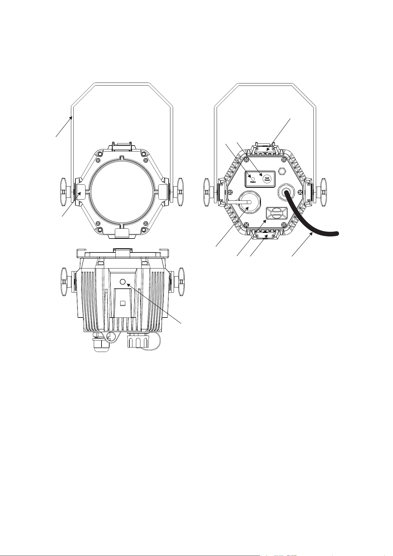
Fixture overview
1
2
6
7
5
8
9
3
4
5
1 – Hanging bracket (can be taken off)
2 – PAR30 sized holder for diffuser or barndoors
3 – Status LED
4 – Test / Reset button
5 – Interlock slots for interlock accessories (4 slots, one on each side of fixture)
6 – Thru connector (chassis mount, with sealing cap)
7 – Safety cable attachment point
8 – Input cable with connector
9 – M8 holes for hanging bracket attachment, maximum bolt length 15 mm (4 holes, one on
each side of fixture). May also be used for mounting fixture if standard interlock
accessories are not suitable.
Martin VDO Atomic Dot user guide 19
Physical installation
Warning! Read ‘Safety information’ on page 8 before installing the fixture.
Wa
rning! The safety and suitability of lifting equipment, installation location,
anchoring method, mounting hardware and electrical installation are the
responsibility of the installer. All local safety regulations and legal requirements
must be observed when installing and connecting the VDO Atomic Dot fixture and
Junction Box. Installation must be carried out by qualified professionals only.
Contact your Martin supplier for assistance if you have any questions about how to install this
product safely.
Fixture location
The VDO Atomic Dot fixture and Junction Box is fully IP65 rated and may be used indoors or in a
temporary outdoor location.
Observe the following limitations in selecting a location:
x Respect the limitations listed under Safety information’ on page 8.
x Do not lo
cate the fixture in an unventilated space.
Ways of mounting the fixture
Warning! All fasteners used to mount VDO Atomic Dot fixtures or arrays of
fixtures must be strong enough to hold the fixtures safely. Install a washer directly
under the head of each fastener when anchoring the mounting bracket to the
installation surface.
The fixture has a number of mounting options:
x Via the hanging bracket to a truss or surface
x A VDO Atomic Dot Half Coupler may be attached directly to one of the interlock slots on
the fixture (without the hanging bracket)
x Multiple fixtures may be interlocked together using the slide-in Interlock Coupler. A
maximum of 16 fixtures may be interlocked in a column. When interlocking fixtures
horizontally, a rigging clamp must be used every 3
rd
fixture to support the array (so a
maximum of 2 unsupported fixtures between each supported one)
x A Pivot Interlock Coupler is available which couples fixtures at any multiple of 15 degrees.
This allows circles or other shapes of fixtures to be created.
x An Interlock Adaptor is available which attaches to one of the interlock slots enabling you
to mount a single VDO Atomic Dot on a microphone stand with standard 5/8 in. thread.
x A Double Width Bracket is available to join 2 fixtures in a 2-lite or 4 fixtures in a 4-lite,
which can then be attached to a truss or surface.
x A Spigot Adapter is available to attach a fixture to standard spigot-compatible
accessories such as floorplates and stands.
x Safety bonds must be fitted to each fixture, even when fixtures are interlocked, using the
safety bond attachment point on the rear.
Warning! The VDO Atomic Dot Half Coupler, Pivot Interlock Coupler, Interlock
Adapter and Spigot Adapter are not suitable for permanent outdoor usage. Long
term exposure to humidity and pollution can affect the correct and safe
functioning of these mechanisms.
20 Martin VDO Atomic Dot user guide
Mounting the fixture on a truss using the hanging bracket
The fixture or array of fixtures can be clamped to a truss or similar rigging structure using the
hanging bracket which allows adjustment of the fixture angle. Use a suitable rigging clamps such
as a G-clamp or a half-coupler clamp fastened to the hanging bracket.
To clamp the fixture or array to a truss:
1. Check that the rigging structure can support at least 10 times the weight of all fixtures and
equipment to be installed on it.
2. Block access under the work area.
3. Bolt a rigging clamp securely to the hanging bracket. The bolts used must be M12, grade 8.8
steel minimum, and fastened with a self-locking nut.
4. Working from a stable platform, mount the fixture on the truss and fasten the rigging clamp
onto the truss.
5. Attach a safety bond to the fixture and loop around a fixed point.
Martin VDO Atomic Dot user guide 21
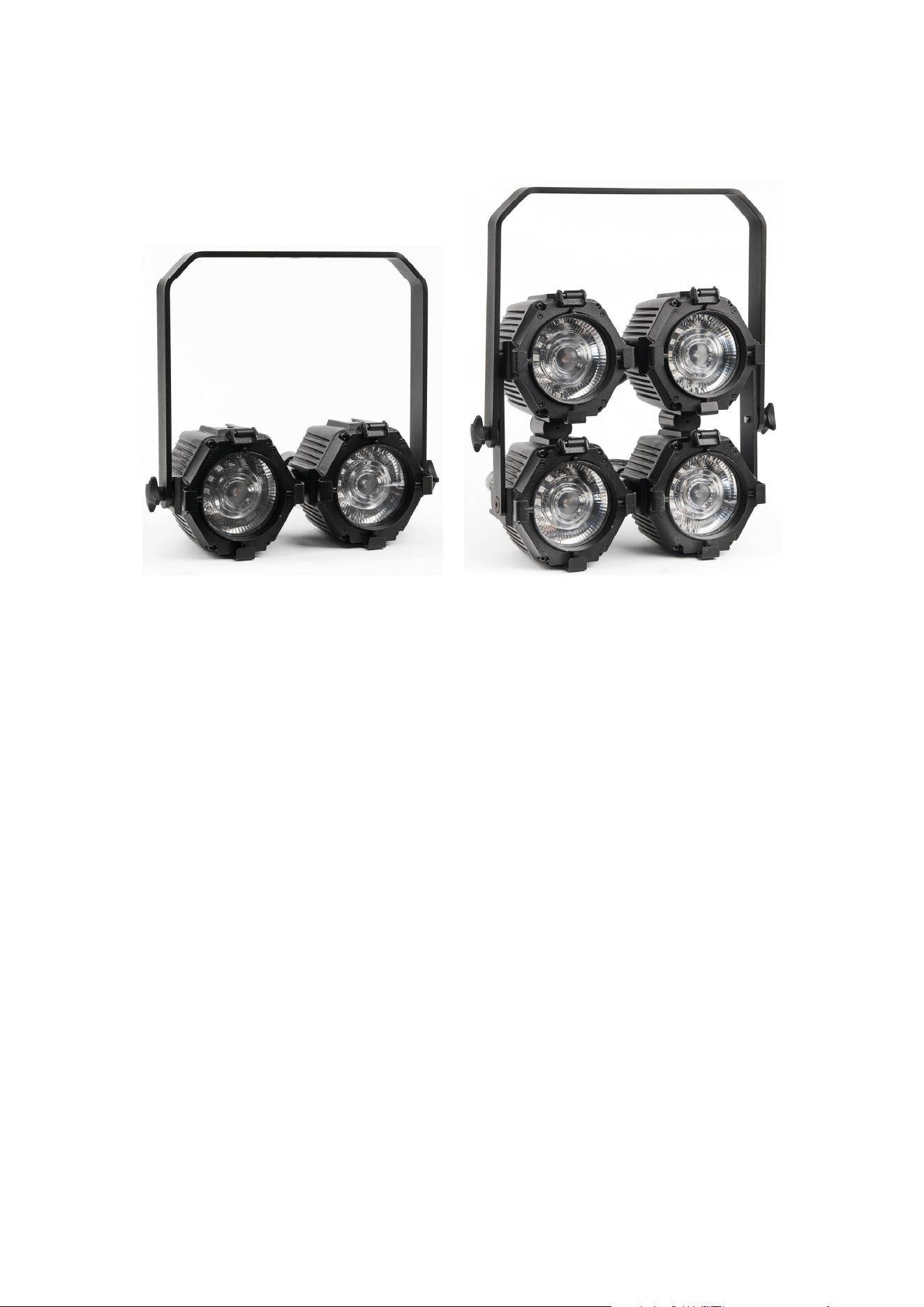
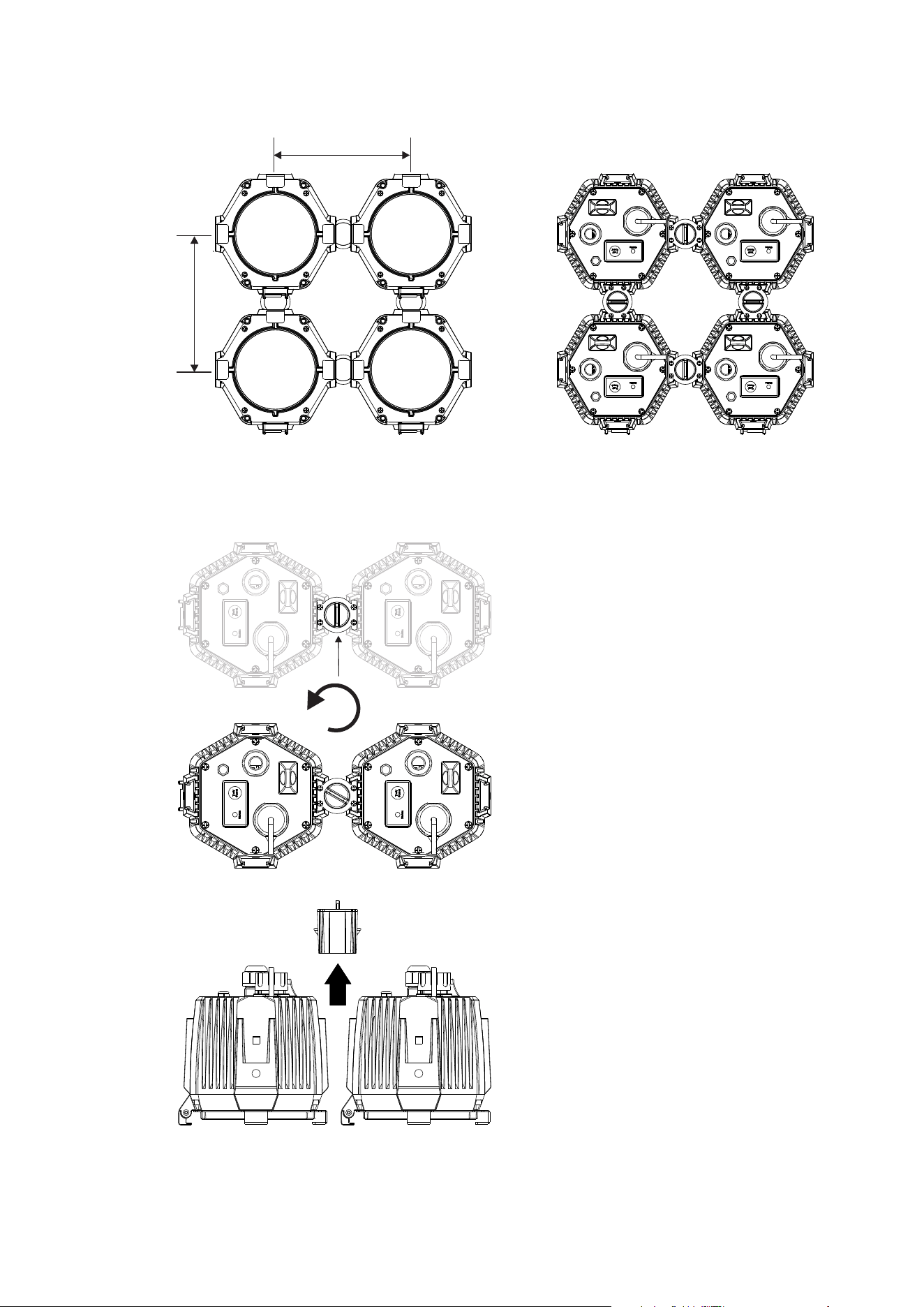
Mounting 2 or 4 fixtures on a truss using the double width hanging bracket
Two or four fixtures can be joined together using the double width bracket to create a 2-lite or 4-
lite fixture. The double width bracket allows adjustment of the fixture angle when clamped to a
truss or similar rigging structure. Use a suitable rigging clamp such as a G-clamp or a half-
coupler fastened to the hanging bracket.
To create a 2-lite:
1. Put aside the 2 interlinking plates and 4 bolts supplied with the double width bracket. These
are not used when creating a 2-lite.
2. Attach two VDO Atomic Dot fixtures side-by-side using a VDO Atomic Dot Coupler (P/N
91610003).
3. Attach the double-width bracket to the joined fixtures using the supplied knobs.
4. Check that the rigging structure can support at least 10 times the weight of all fixtures and
equipment to be installed on it.
5. Block access under the work area.
6. Bolt a rigging clamp securely to the double width hanging bracket. The bolts used must be
M12, grade 8.8 steel minimum, and fastened with a self-locking nut.
7. Working from a stable platform, mount the fixture-assembly on the truss and fasten the
rigging clamp onto the truss.
8. Attach a safety bond to both fixtures and loop around a fixed point.
To create a 4-lite:
1. Attach four VDO Atomic Dot fixtures in a 2 by 2 array using 4x VDO Atomic Dot Couplers
(P/N 91610003).
2. Attach the 2 interlinking plates supplied with the double width bracket assembly to the left
side and right side of the array, using the supplied M8 bolts, fitted into the M8 holes in the
sides of the fixtures.
22 Martin VDO Atomic Dot user guide
3. Attach the double-width bracket to the center holes of the interlinking plates, using the
supplied knobs.
4. Check that the rigging structure can support at least 10 times the weight of all fixtures and
equipment to be installed on it.
5. Block access under the work area.
6. Bolt a rigging clamp securely to the double width hanging bracket. The bolts used must be
M12, grade 8.8 steel minimum, and fastened with a self-locking nut.
7. Working from a stable platform, mount the fixture-assembly on the truss and fasten the
rigging clamp onto the truss.
8. Attach a safety bond to all four fixtures and loop around a fixed point.
Mounting the fixture on a truss using direct clamp
The VDO Atomic Dot Half Coupler may be directly mounted to the fixture or array of fixtures
using one of the interlock slots on any side.
To rig using a directly attached clamp:
1. Check that the rigging structure can support at least 10 times the weight of all fixtures and
equipment to be installed on it.
2. Block access under the work area.
3. Slide VDO Atomic Dot Half Couplers into the fixture interlock slot on one or more fixtures as
required.
4. Working from a stable platform, lift the fixture(s) to the truss and fasten the half coupler clamp
onto the truss.
5. Attach a safety bond to the fixture and loop around a fixed point. Each fixture must have an
individual safety bond even when interlocked into an array.
Martin VDO Atomic Dot user guide 23
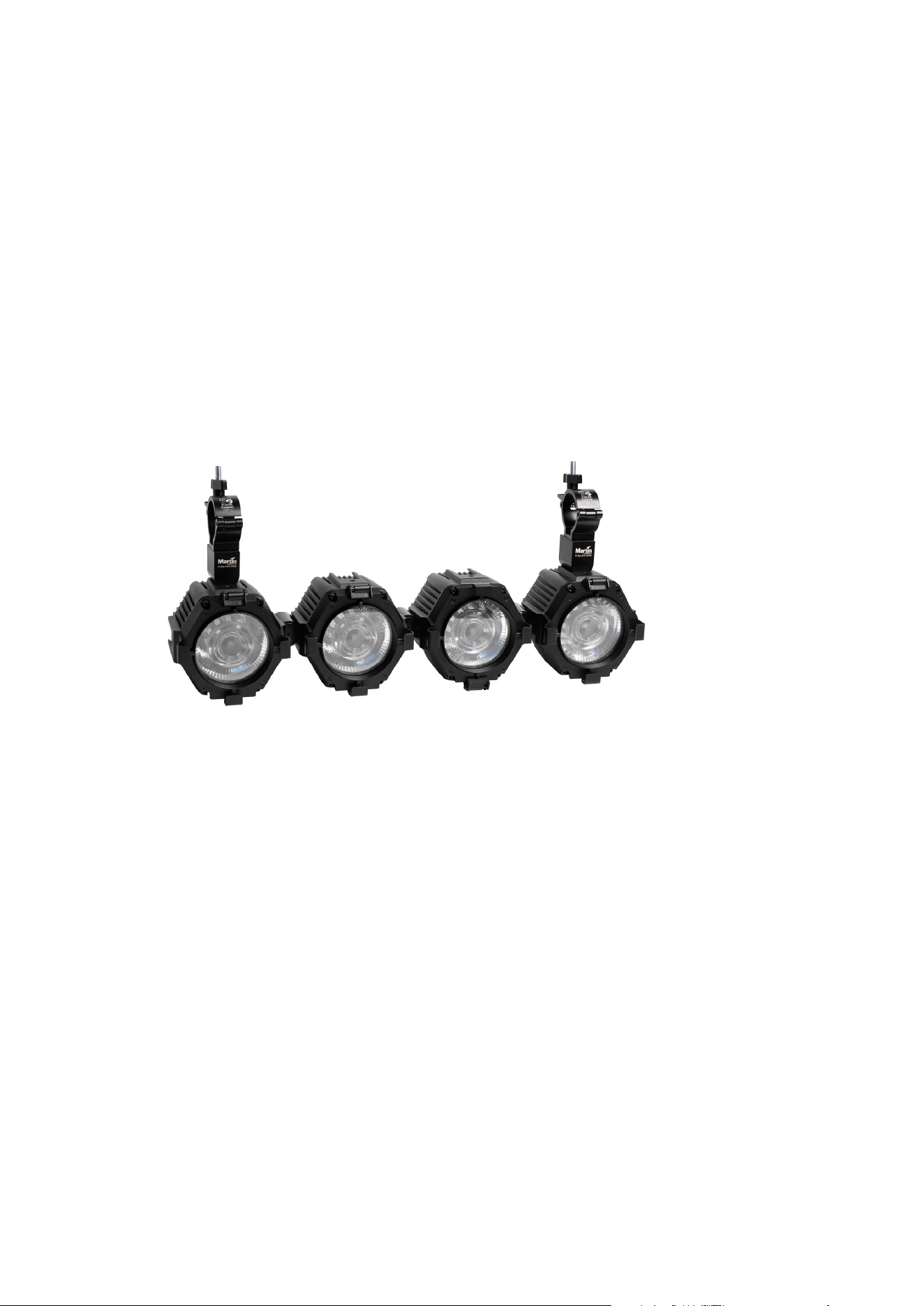
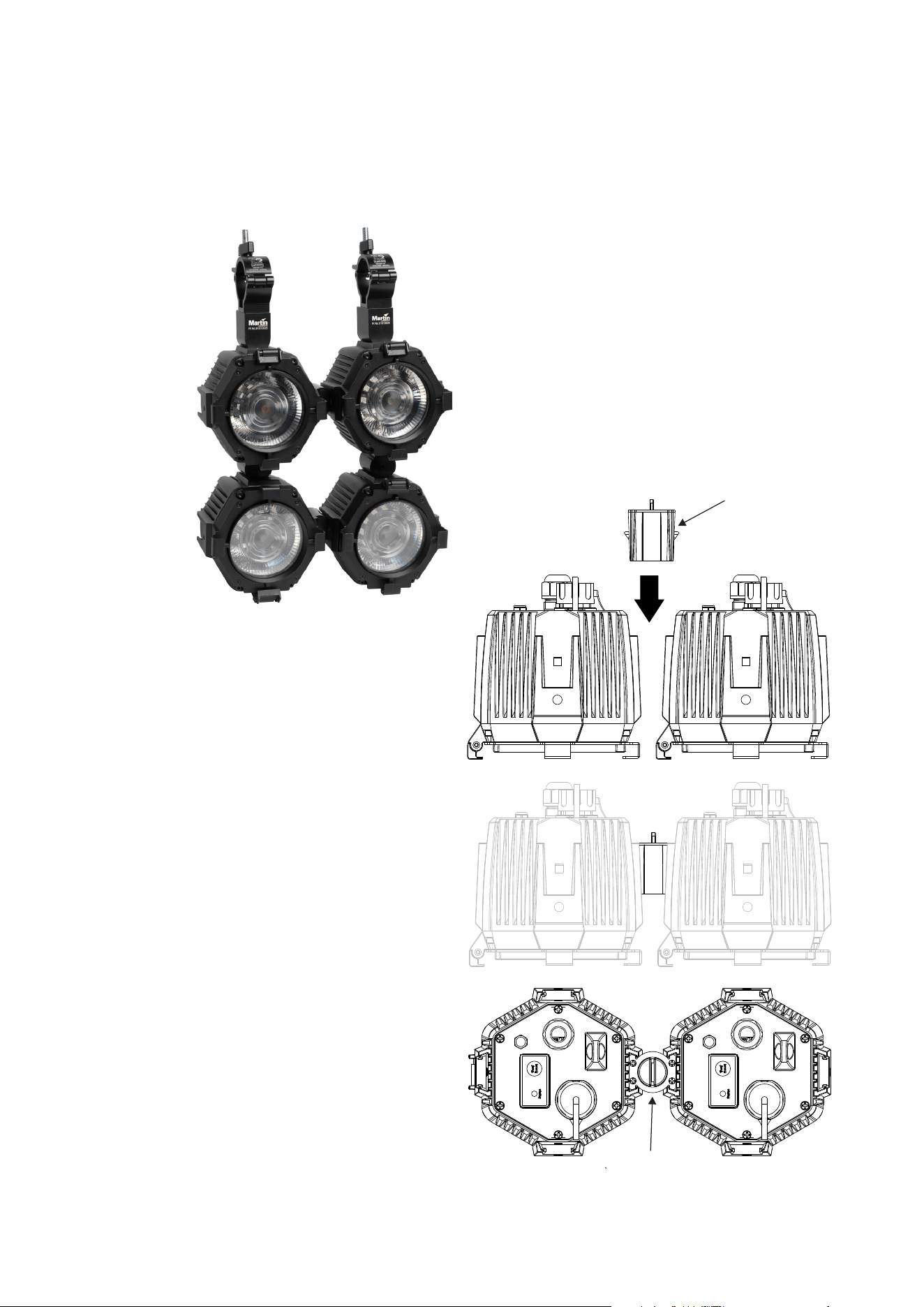
Interlocking multiple fixtures
Multiple fixtures may be interlocked on any side using the slide-in interlock coupler to form arrays
of any shape.
To install the Interlock Coupler, locate two
fixtures side by side and slide in the coupler
(1) from the rear. The coupler has two
retention clips which lock into each fixture.
Ensure the release key (2) is oriented as
shown so that the clips are secured in place.
Note:
x A maximum of 16 fixtures may be
interlocked in a column.
x When interlocking fixtures
horizontally, a rigging clamp must be
used every 3
rd
fixture to support the
array (so a maximum of 2
unsupported fixtures between each
supported one)
1
2
24 Martin VDO Atomic Dot user guide
When fixtures are interlocked, the spacing is 150mm.
150
150
To remove the coupler, twist the release key to retract the clips. The coupler can then be slid out
towards the rear of the fixtures.
Martin VDO Atomic Dot user guide 25
The Pivot Coupler, Half Coupler, Interlock Adapter and Spigot Adapter use the same locking
mechanism.
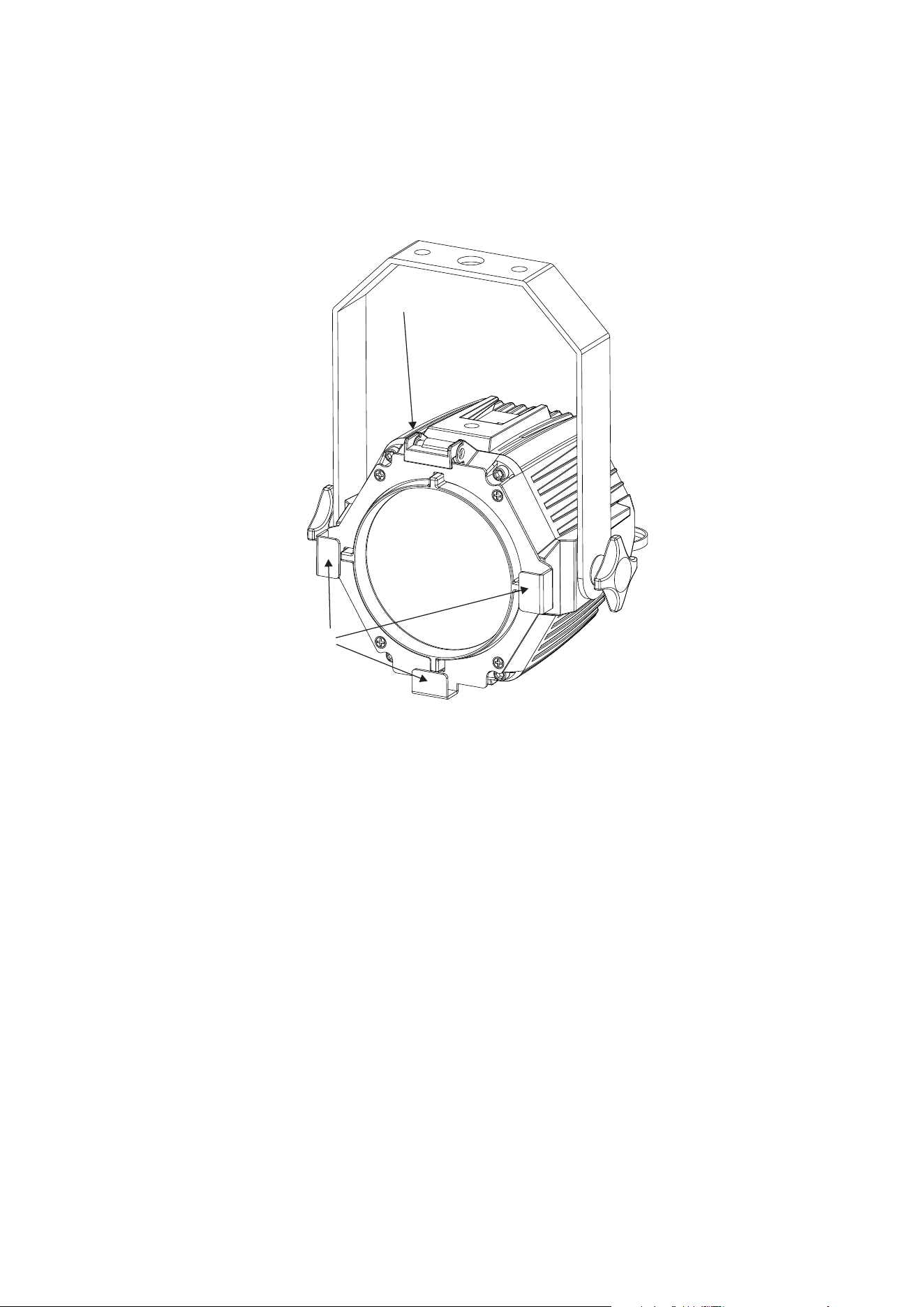
Installing optical accessories
Installing one of the optical accessories available from Martin® for the VDO Atomic Dot takes a
few seconds. No tools are required.
1
2
To install an optical accessory:
1. Slide and lift up the hinged retaining clip (1) on the top of the VDO Atomic Dot and hold it
back.
2. Slide the optical accessory into the PAR30-sized holders (2) on the front of the fixture,
ensuring that the accessory is correctly located on all sides.
3. Gently release the retaining clip and ensure it locks the accessory in position.
When using the Martin VDO Atomic Dot Diffuser, make sure that you insert it with the matt side
towards the fixture.
26 Martin VDO Atomic Dot user guide
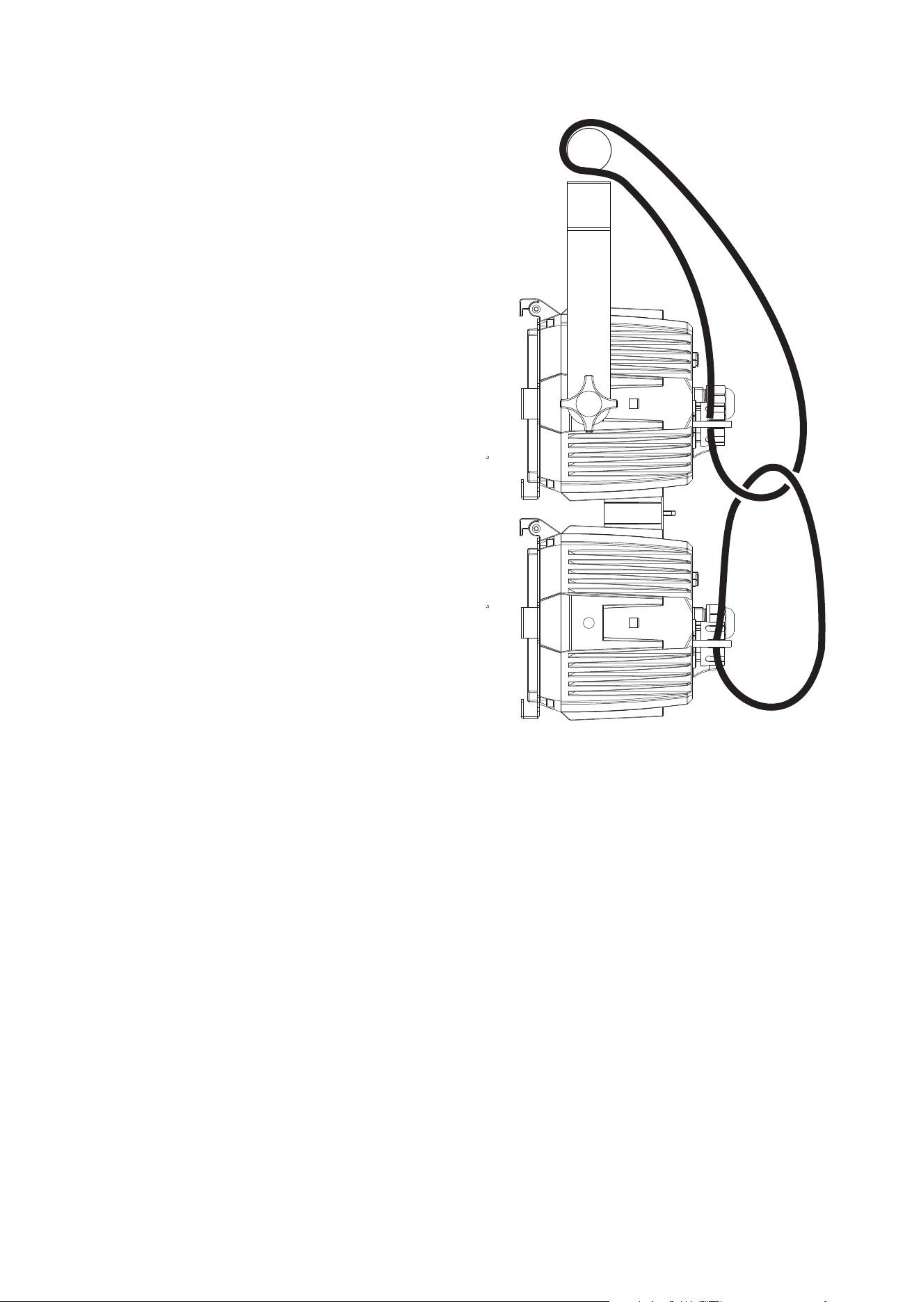
Safety bonds
To protect against the fixtures falling if the main
rigging point fails, you should fit a safety bond to
the attachment point on the back of each fixture.
If fixtures are linked together into a larger array,
you should still attach a safety bond to each fixture
since a failure of a coupler could cause parts of the
assembly to fall. However to make rigging easier
you can attach the top one round a fixed point,
then loop the lower safety bonds into each other as
shown in the picture.
Martin VDO Atomic Dot user guide 27
AC power and data connection
Warning! Read ‘Safety information’ on page 8 before installing the fixture.
For p
rotection from electric shock, the power input to the Junction Box or Break-In
cable must be grounded (earthed). The power distribution circuit must be equipped
with a 16A fuse or circuit breaker and ground-fault (earth-fault) protection.
AC power and control data are connected to the Junction Box or Break-In cable. Up to 32 VDO
Atomic Dot fixtures may then be connected in a daisy chain to each Junction Box or Break-In
cable using a hybrid PDE cable which carries both power and data.
Safety limits for connecting devices
As the fixtures are connected in a chain, there is a limit to how many fixtures you can link
together and how far apart they can be.
x Maximum of 32 fixtures connected in a chain.
x When DMX is being used as control protocol, the total length of DMX cable and Hybrid
PDE cable combined must not exceed 300 m (measured between lighting console, DMX
node or DMX splitter and last fixture on the chain).
x When Art-Net, sACN or P3 is being used as control protocol, the combined length of
Ethernet cable (between network switch and junction box) and hybrid PDE cable to first
fixture must not exceed 90 m. The length of hybrid PDE cable between any two daisy-
chained fixtures may also not exceed 90 m.
x Install the sealing cap on the thru connector of the last fixture in the chain.
AC power connection to Junction Box or Break-In cable
Do not use an external dimming system to supply power to the Junction Box or Break-In cable
and fixtures, as this may cause damage to the fixtures that is not covered by the product
warranty.
Socket outlets or external power switches used to supply the system with power must be located
near the system and easily accessible so that the system can easily be disconnected from power.
If you install a power plug on the power cable, install a grounding type (earthed) plug with integral
cable grip that is suitable for your local mains voltage at a current of 16A. Follow the plug
manufacturer’s instructions and connect the wires in the power cable as shown in this table:
Live or L Neutral or N
Earth, Ground or
US system
Black White Green
EU system
Brown Blue Yellow/green
The fixture has an auto-ranging power supply that accepts AC mains power at 100-240 V at
50/60 Hz. Do not apply AC mains power at any other voltage or frequency to the fixture.
28 Martin VDO Atomic Dot user guide
Data connection to Junction Box or Break-In cable
The VDO Atomic Dot fixtures may be controlled by DMX512, Art-Net, sACN, or Martin P3
protocol. The data connection is made to the junction box and then linked to the fixtures via the
PDE connections.
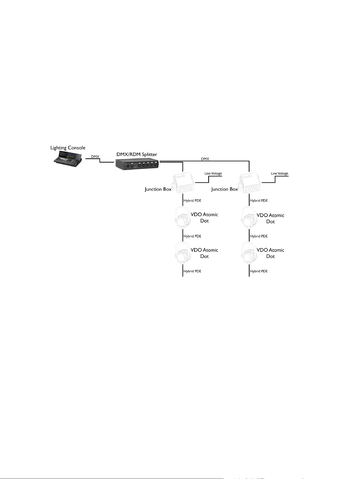
Using DMX512
In a DMX-con
trolled system, an RDM-compliant DMX lighting controller sends a DMX control
data signal over a DMX link to the junction boxes / break-in cables of the system, and then over
the hybrid link to the VDO Atomic Dot fixtures.
A DMX pass – through connector is only provided on the Active Junction Box. When using a
Passive Junction Box or Break-In Cable, and you need to connect multiple chains to the same
DMX line, you must use an RDM-compliant splitter as described below (and shown in the
diagram below). This example shows the passive PDE junction box being used.
The DMX link requires DMX cable. It can be maximum 300 m (1000 ft.) in length and must run in
one single daisy-chain, but it can be extended or split into branches using an RDM-compliant
amplifier/splitter. Alternatively, you can run the DMX signal from the controller over Ethernet
cable using Art-Net protocol and convert it to a DMX-compliant signal with an Art-Net to DMX
converter.
For reliable DMX and RDM data transfer, it is recommended to terminate each branch with a
termination plug – this contains a 120 ohm resistor between the cold and hot DMX data lines
(pins 2 and 3 on XLR5, pins 4 and 7 on PDE connector). This means that both an unused DMX
through port on an Active Junction Box as well as the female PDE connector of the last fixture on
a chain needs to be fitted with such a termination plug.
The total length of DMX cable and Hybrid PDE cable combined must not exceed 300 m
(measured between lighting console, DMX node or DMX splitter and last fixture on the chain).
If you would like assistance with creating a DMX link, your Martin® supplier will be glad to advise.
The number of VDO Atomic Dots that you can control on one DMX link is limited by the number
of DMX channels the dots will use and the 512 DMX channels available in one DMX universe at
the DMX controller. Each time you have used 512 channels, you must create a new DMX link
that is connected to a new DMX universe on the controller. Note that this limit applies to the DMX
link. The maximum safety limits that apply to the chain of dots and cable (see “Safety limits for
connecting devices” on page 27) take priority and must be respected in all cases.
D
MX512 data is connected to the junction box using the XLR5 connector. The pin-out is:
x pin 1 = shield
Martin VDO Atomic Dot user guide 29
x pin 2 = cold (-)
x pin 3 = hot (+).
Pins 4 and 5 in the XLR connectors are not used.
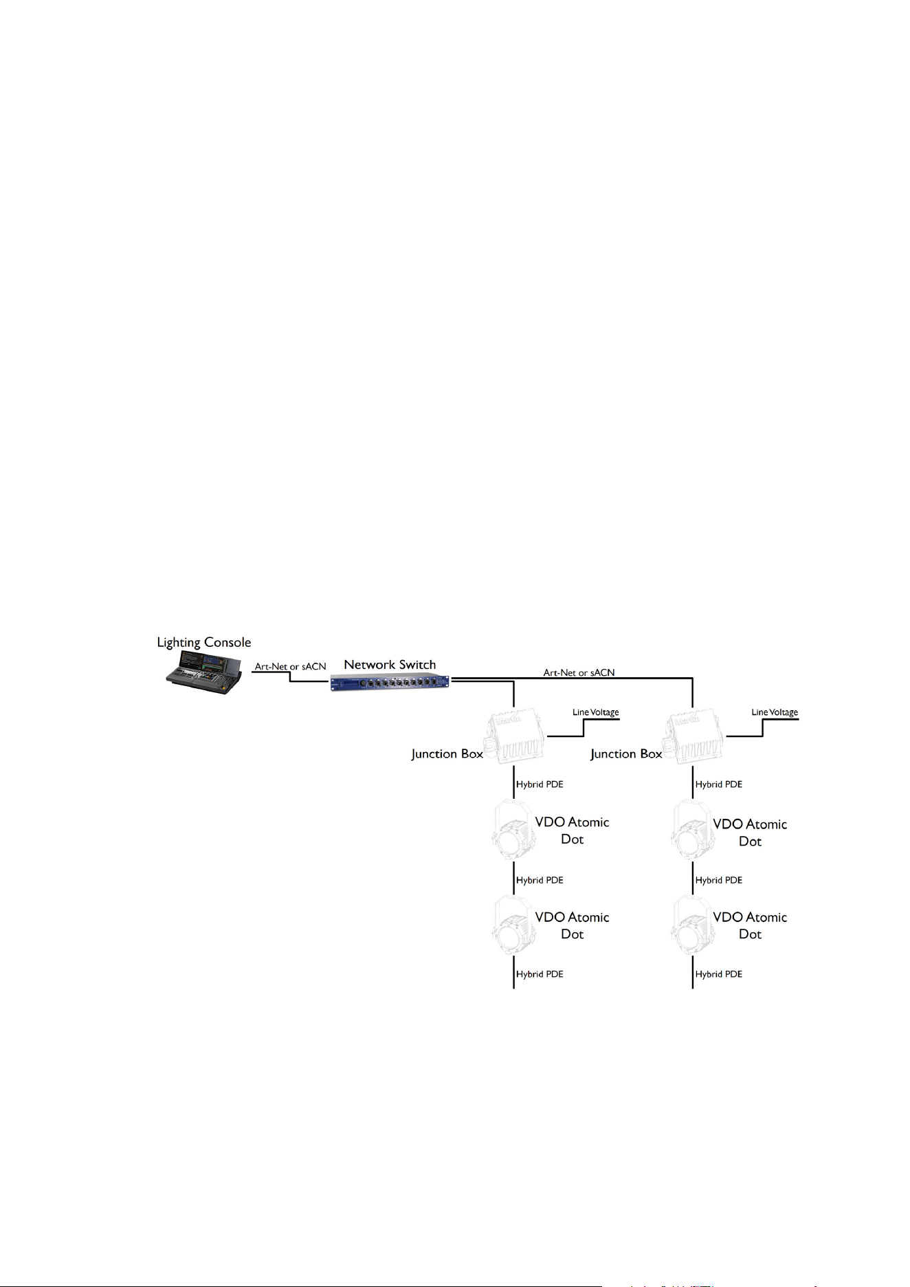
Using Art-Net or sACN
Art-Net or s
ACN data is connected to the system using the etherCON socket on the Junction Box
or Break-In Cable. Each Junction Box/Break-In cable must have its own Ethernet connection
from a network switch, unless you are using an Active PDE Junction Box, which has an Ethernet
thru port, allowing you to daisy chain multiple Active Junction Boxes in an Ethernet chain.
x Please ensure that network switch can operate at 100Mbit Ethernet link speed towards
the junction boxes, as the VDO Atomic Dot can only operate at that link speed.
x The combined length of Ethernet cable (between network switch and junction box) and
hybrid PDE cable to first fixture must not exceed 90 m. The length of hybrid PDE cable
between any two daisy-chained fixtures may also not exceed 90 m.
x A shielded Ethernet cable must be used between the Network Switch and the Junction
Box / Break-In Cable. Use shielded twisted-pair Ethernet cable of type S/UTP, SF/UTP,
S/STP or SF/STP only. The cable must be rated Cat 5e or better. The cable shield must
be electrically connected to connector housings, and the other devices on the data link
must also support shielded connections.
This example shows the passive PDE junction box being used.
30 Martin VDO Atomic Dot user guide
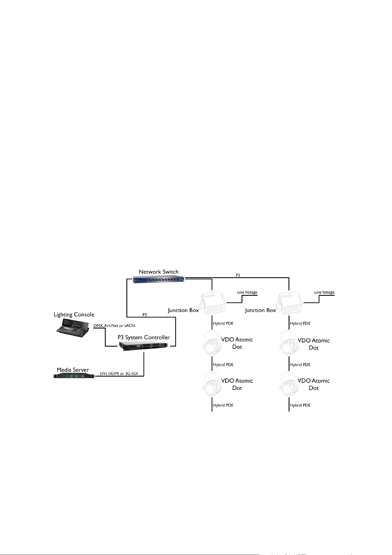
Using P3
The Ma
rtin P3 System Controller combines control information from the lighting console with
video information from a media server. This is distributed to the fixtures using a network switch.
Each Junction Box must have its own Ethernet connection from the network switch, unless you
are using an Active PDE Junction Box, which has an Ethernet thru port, allowing you to daisy
chain multiple Active Junction Boxes in an Ethernet chain..
x Please ensure that network switch can operate at 100Mbit Ethernet link speed towards
junction boxes, as the VDO Atomic Dot can only operate at that link speed.
x Please ensure that network switch can operate at 1Gbit Ethernet link speed towards the
P3 System Controller, as it can only operate at that link speed.
x The combined length of Ethernet cable (between network switch and junction box) and
hybrid PDE cable to first fixture must not exceed 90 m. The length of hybrid PDE cable
between any two daisy-chained fixtures may also not exceed 90 m.
x A shielded Ethernet cable must be used between the Network Switch and the Junction
Box / Break-In Cable. Use shielded twisted-pair Ethernet cable of type S/UTP, SF/UTP,
S/STP or SF/STP only. The cable must be rated Cat 5e or better. The cable shield must
be electrically connected to connector housings, and the other devices on the data link
must also support shielded connections.
x Other P3-compatible fixtures such as the MAC Aura PXL and P3 PowerPort 1500 can be
connected to the same network switch to operate all together from the same P3 System
Controller.
The example below shows a system using a passive PDE junction box.
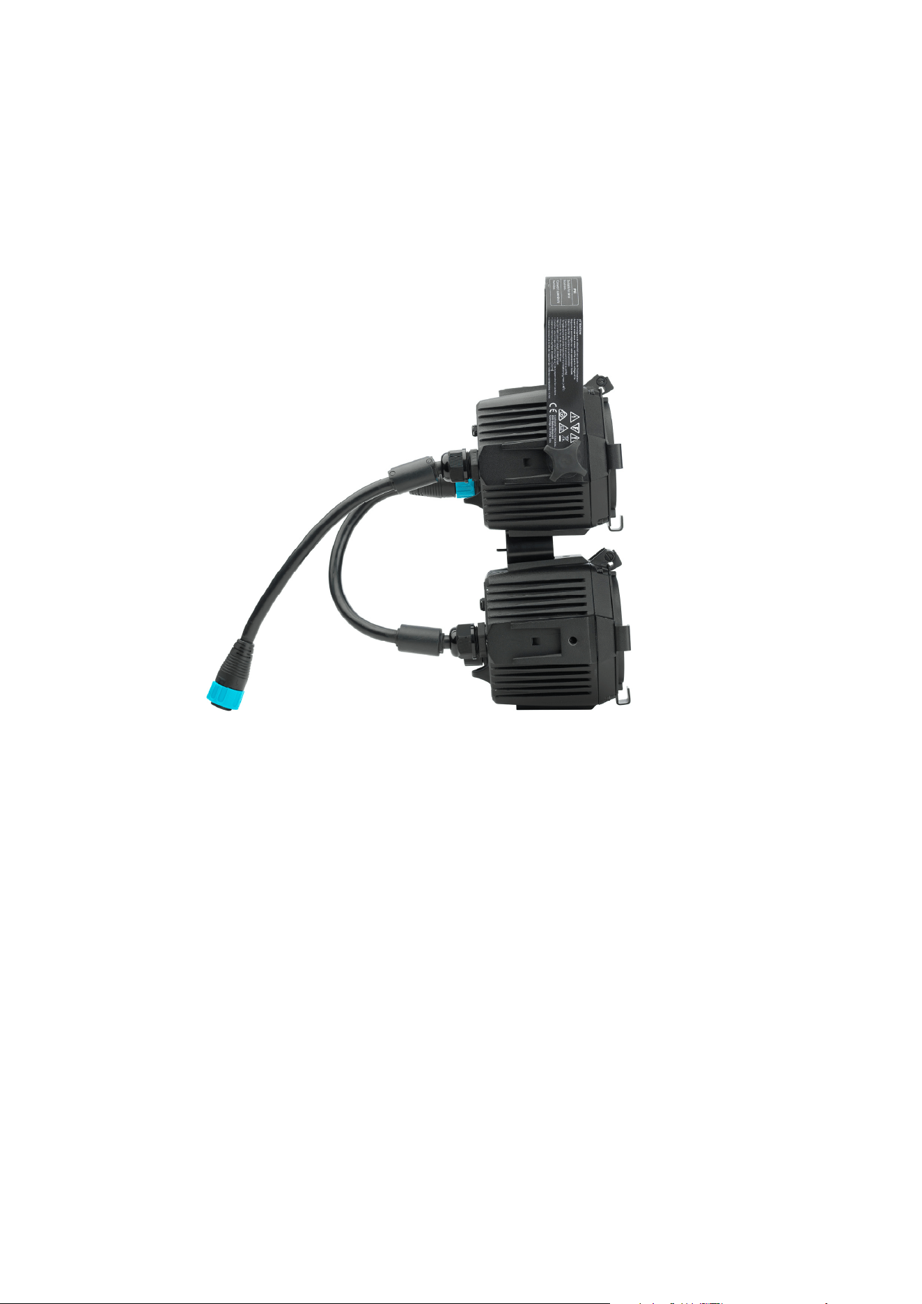
PDE connections between fixtures
The VDO Atomic Dot fixtures are linked to each other and the Junction Box or Break-In cable
using a PDE connection which carries both power and data.
x To make the connection, align the pins of the connectors and push together. The
connector will lock automatically.
x To remove the connection, twist the locking ring counter-clockwise to unlock and then
pull apart.

Martin VDO Atomic Dot user guide 31
System Setup
All setup options for the VDO Atomic Dot are configured over the data link.
If you are using a Martin P3 system to control the fixture, please refer to the P3 System Controller
user manual and instruction videos.
For DMX, Art-Net and sACN the fixture is configured using RDM.
It is also possible to configure the VDO Atomic Dot fixtures using a P3 System Controller (or P3-
PC) to set DMX start addresses, DMX modes, DMX universes and other parameters. Once the
fixtures are configured you can then run the fixtures directly using DMX, Art-Net or sACN without
using the P3 System Controller.
Setting options by RDM
The VDO Atomic Dot fixture is remotely configured over the DMX line using RDM.
A full list of the RDM functions that the VDO Atomic Dot fixture supports is given at the end of this
chapter. These functions are generally referred to using the more specific term ‘PIDs’ or
‘Parameter IDs’.
Scanning for RDM devices on the data link
Before you can communicate with fixtures using RDM, you must send a scan command (also
called a device discovery command) to all the devices on the data link so that the RDM controller
can identify them. It does this by retrieving each device’s factory-set unique identifier (UID). This
process can take some time depending on the number of devices on the link.
To identify the fixtures on the link:
1. Check that the fixtures are correctly connected to the RDM controller on the data link and that
power is applied to all fixtures.
2. Give the controller time to identify the devices on the link and prepare for communication with
the devices.
Getting status and setting options by RDM
The status and options listed in the table below can be read and set by RDM.
You can set an option on one fixture by sending a unicast RDM command to that one fixture only,
or you can set the same option on all the fixtures on the data link by sending a broadcast RDM
command to all the devices on the link.
For status reading, you can only use unicast RDM to read information from an individual fixture.
Martin Companion and RDM
The Martin Companion Windows application (downloadable free of charge from the Martin
website at www.martin.com) gives access to all the fixture’s RDM parameters. It supports the
fixture’s standard and manufacturer-specific PIDs. It gives full control of all fixture settings
remotely, eliminating the need to physically climb to the fixture in a rig, for example.
Martin Companion can also update multiple RDM parameters at once, using the built-in Settings
Template system.
32 Martin VDO Atomic Dot user guide
RDM
As a minimum, the VDO Atomic Dot fixtures support the following RDM functions:
RDM DISCOVERY
DISC_UNIQUE_BRANCH
DISC_MUTE
DISC_UN_MUTE
STATUS COLLECTION GET SET
QUEUED_MESSAGE
9
STATUS_MESSAGES
9
STATUS_ID_DESCRIPTION
9
CLEAR_STATUS_ID
9
RDM INFORMATION GET SET
SUPPORTED_PARAMETERS
9
PARAMETER_DESCRIPTION
9
PRODUCT INFORMATION GET SET
DEVICE_INFO
9
DEVICE_MODEL_DESCRIPTION
9
MANUFACTURER_LABEL
9
DEVICE_LABEL
9 9
FACTORY_DEFAULTS
9 9
SOFTWARE_VERSION_LABEL
9
DMX SETUP GET SET
DMX_PERSONALITY
9 9
DMX_PERSONALITY_DESCRIPTION
9
DMX_START_ADDRESS
9 9
SLOT_DESCRIPTION
9
SENSORS GET SET
SENSOR_DEFINITION
9
SENSOR_VALUE
9 9
USAGE INFORMATION GET SET
DEVICE_HOURS
9
DEVICE_POWER_CYCLES
9
Martin VDO Atomic Dot user guide 33
CONTROL GET SET
IDENTIFY_DEVICE
9 9
RESET_DEVICE
9
PERFORM_SELFTEST
9 9
SELF_TEST_DESCRIPTION
9
NETWORK CONFIGURATION GET SET
LIST_INTERFACES
9
INTERFACE_LABEL
9
INTERFACE_HARDWARE_ADDRESS_TYPE1
9
IPV4_DHCP_MODE
9
IPV4_CURRENT_ADDRESS
9
IPV4_STATIC_ADDRESS
9 9
INTERFACE_APPLY_CONFIGURATION
9
MARTIN CUSTOM GET SET
DMX_RESET_ENABLE
9 9
FIXTURE_ID
9 9
DIMMER_CURVE
9 9
VIDEO_TRACKING
9 9
STROBE_BEHAVIOR
9 9
SERIAL_NUMBER
9

34 Martin VDO Atomic Dot user guide
Using the VDO Atomic Dot
Warning! Read ‘Safety information’ on page 8 before applying power to the VDO
Atomic
Dot.
Do not use the VDO Atomic Dot if the ambient temperature exceeds 40° C (104° F)
or falls below 0° C (32° F).
Thermal regulation
The VDO Atomic Dot uses passive cooling without a fan, and controls its temperature by
dimming down automatically if it gets too hot, for example on full white it will dim after about 10
seconds to a lower intensity. At high ambient temperatures the output will also be reduced.
Video display using P3
The VDO Atomic Dot can display video from all common video sources. The video signal must be
sent to a Martin® P3 controller and then distributed to fixtures. The P3 controller lets you map,
configure and control an installation containing VDO Atomic Dots (and other Martin® P3 video
display products if you have them).
Once the VDO Atomic Dot fixtures are mapped and addressed on the P3 System Controller, it is
possible to map video onto them, while still having control from the lighting desk. At any given
moment the output from the fixture can be controlled by video content, DMX channels, internal
effect macros or a mix.
See the P3 controller documentation for details.
DMX control
The VDO Atomic Dot can display effects controlled by DMX (either using the 5-pin XLR, via Art-
Net / sACN or via DMX sent through the P3 System Controller).
Five DMX modes are available:
x 1 channel mode: uses a single DMX channel and operates the fixture as a white
“blinder” with automatic tungsten fade effect
x 3 channel mode: gives strobe functionality of intensity / duration / rate, same as Atomic
3000 DMX/LED (no backlight functions)
x 4 channel mode: As 3 channel mode but with an additional effects channel, same as
Atomic 3000 DMX/LED (no backlight functions)
x Basic mode: uses 19 DMX channels and gives RGB color mixing of backlight/aura,
strobe effects and pre-programmed dynamic effects. P3 video data can also be
superimposed or mixed under DMX control.
x Extended mode: uses 64 DMX channels to add to Basic mode by allowing individual
control of the 16 LEDs in the backlight/aura. P3 video data can also be superimposed or
mixed under DMX control.
See “DMX protocols” on page 38 for full details of DMX control.
An RDM
-compatible DMX controller or P3 System Controller is required so that you can address
and configure the fixtures. See the DMX/RDM controller documentation for details.
LED PWM frequency control
The PWM frequency of the VDO Atomic Dot LEDs has been chosen carefully to avoid flickering
on camera. In some rare situations – for example when using cameras with non-standard
settings – it may be necessary to adjust the LED PWM frequency manually.

Martin VDO Atomic Dot user guide 35
From firmware version 1.4.0, you can adjust the PWM frequency via DMX by sending value 255
on the FX Selection channel. Once activated, the FX Speed and Direction channel will control the
LED PWM frequency. Note that this change is not stored permanently in the fixture, so you have
to keep the FX Selection and FX Speed/Direction channels at the chosen values in order to keep
the LED PWM frequency at the corresponding custom value.
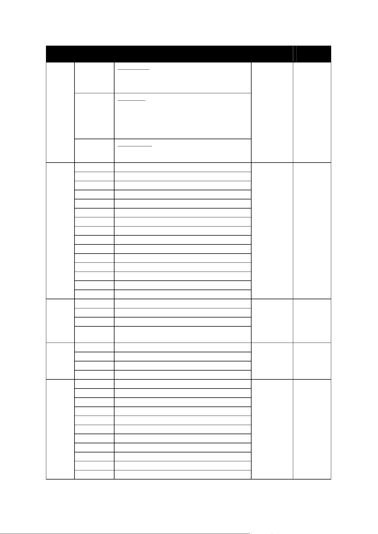
You can adjust PWM frequency as follows:
DMX value sent on FX Speed and
Direction Channel
LED PWM frequency
0 2400Hz (Default PWM frequency)
1-127 Adjustment in steps from 2400Hz to 3000Hz
128 3000Hz
129-254 No function
255 High speed PWM Frequency Mode (24000Hz)
Status LED
The only user controls on the VDO Atomic Dot are a status LED and a pushbutton. The function
of these is described below.
LED indication Meaning
Blue Constant Busy (e.g. booting up or writing to flash memory)
Red Constant Error. The fixture has encountered a fatal error and cannot run.
Red Flashing No control source detected (no protocols detected on DMX or Ethernet).
Green Flashing Ready. P3 packets detected, but fixture not in joined state.
Green Constant Running normally in P3 mode (P3 joined).
Cyan Flashing Ready. Fixture in DMX mode but not receiving valid DMX data.
Cyan Constant Running normally in DMX mode.
Yellow Constant Overtemperature.
Magenta Flashing Ready. Fixture in Art-Net or sACN mode but not receiving valid DMX data.
Magenta Constant Running normally in Art-Net or sACN mode.
Pushbutton functions
The pushbutton can be used to activate internal test patterns within the fixture, perform a fixture
reboot or perform a factory reset of the fixture (just like other Martin LED Video fixtures).
If the pushbutton is given a short press, the first internal test pattern is activated. If the
pushbutton is then given another short press, the next internal test pattern is activated. This way
the user can “step” through the different internal test patterns.
Press once: 16 backlight LEDs to full red
Press again: 16 backlight LEDs to full green
Press again: 16 backlight LEDs to full blue
Press again: 16 backlight LEDs to full white
Press again: White beam LED at full on (backlight LEDs off)
Press again: Dynamic test pattern activated

36 Martin VDO Atomic Dot user guide
Press again: Test patterns stopped, fixture returns to normal operation
If the button is pressed, and kept held in for 5 seconds, the Status LED will turn blue. If the user
then releases the button, the fixture will perform a normal reboot.
If the button is pressed, and kept held in for 8 seconds, the Status LED will turn white. If the user
then releases the button, the fixture will perform a factory reset (return to factory default/backup
firmware image).

Martin VDO Atomic Dot user guide 37
Maintenance
Read Safety information on page 8 before maintaining the fixture. Always
com
ply with the safety instructions.
Refer any service operation not described in this user manual to a qualified
service technician.
Excessive dust, smoke fluid, and particle buildup degrades performance, causes
overheating and will damage the fixture. Damage caused by inadequate
cleaning or maintenance is not covered by the product warranty.
Disconnect mains power before cleaning or servicing the fixture.
Fixtures must be serviced in an area where there is no risk of anyone being
injured by failing parts, tools or other materials.
Cleaning
Cleaning schedules vary depending on the operating environment. It is therefore impossible to
specify precise cleaning intervals for the VDO Atomic Dot. Environmental factors that may result
in a need for frequent cleaning include airborne dust and pollution.
Inspect products frequently to see whether cleaning is necessary. If in doubt, consult your
Martin® dealer about a suitable maintenance schedule.
To clean the product, use warm water and a soft brush or a low-pressure or medium-pressure
water jet. Use car shampoo to help remove dirt and grease. If possible, dry with a soft cloth to
avoid streaking. Do not use a stiff brush or scouring pad. Do not use solvents or abrasives.
LED performance
Martin® use the best components available, but the characteristics of all LEDs change gradually
over many thousands of hours of use. Not all colors change at the same rate, and rates of
change vary depending on factors such as temperature and how intensively a particular color is
used. Because of the changes, overall light output and the exact hues obtained from specific
color mixes in all LED-based products can be expected to shift slightly over time.
To help you obtain consistent output despite these changes, Martin® P3 software from version
4.1.0 contains the P3 Fixture Adjuster tool. This feature lets you compensate for changes in LED
characteristics and restore initial output and color authenticity levels. Please contact Martin® for
more details.
Installing new software
It may be necessary to upload new software (i.e. device firmware) to the VDO Atomic Dot if it
appears to have a software-related fault or if you want to update to a newer software version.
Software for Martin® products is available from the Martin® website.
The VDO Atomic Dot software can be installed from the P3 System Controller over the P3 data
link. See the P3 System Controller user manual for software installation instructions.
Alternatively software may be installed over the DMX data link using the Martin Companion cable
and Martin Companion application.
38 Martin VDO Atomic Dot user guide
DMX protocol
The VDO Atomic Dot has five possible DMX modes
DMX Mode DMX channels Functions
1 channel 1 Single channel “blinder” with automatic tungsten effect
3 channel 3 As Atomic 3000 DMX/LED (no backlight)
4 channel 4 As Atomic 3000 DMX/LED (no backlight)
Basic 19 Including Aura backlight control and P3 mode control
Extended 64 As Basic mode, but including individual control over 16 Aura
backlight pixels
x While in Basic mode the DMX control of the Aura backlight does not offer individual pixel
control, the pixels can still be driven individually using the P3 System Controller pixels.
DMX mode 1 channel
Channel Value Function Fade Status
Default
Value
Dimmer
1
0 - 255
Close → Open
Fade 0
Notes:
x Fixture will automatically reduce intensity to control temperature when running at high
power for too long
x Aura Backlight will be driven automatically to emulate tungsten effect
DMX mode 3 channel
Channel Value Function Fade Status
Default
Value
Beam Flash Intensity
0 Blackout
1
1 - 255
Minimum → Maximum Intensity
Snap 0
Beam Flash Duration
2
0 - 255
7 → 650 ms
Snap 0
Beam Flash Rate
3
0 - 255
0.289 → 16.67 Hz
Snap 0
Notes:
x Fixture will automatically reduce intensity to control temperature when running at high
power for too long
x Aura Backlight is not used in this mode
x As Atomic 3000 DMX/LED 3-Channel Mode
Martin VDO Atomic Dot user guide 39
DMX mode 4 channel
Channel Value Function Fade Status
Default
Value
Beam Flash Intensity
0 Blackout
1
1 - 255
Minimum → Maximum Intensity
Snap 0
Beam Flash Duration
2
0 - 255
7 → 650 ms
Snap 0
Beam Flash Rate
3
0 - 255
0.289 → 16.67 Hz
Snap 0
Beam Special Effects
0 - 5 No Effect
6 - 42 Ramp Up
43 - 85 Ramp Down
86 - 128 Ramp Up, Down
129 - 171 Random
172 - 214 Lightning
4
215 - 255 Spikes (flash over low light)
Snap 0
Notes:
x Fixture will automatically reduce intensity to control temperature when running at high
power for too long
x Aura Backlight is not used in this mode
x As Atomic 3000 DMX/LED 4-Channel Mode
DMX mode Basic
Basic Value Function Fade Status
Default
Value
Beam Flash Intensity
0 Blackout
1 - 2
1 - 65535
Minimum → Maximum Intensity
Snap 0
Beam Flash Duration
3
0 - 255
7 → 650 ms
Snap 0
Beam Flash Rate
4
0 - 255
0.289 → 16.67 Hz
Snap 0
Beam Special Effects
0 - 5 No Effect
6 - 42 Ramp Up
43 - 85 Ramp Down
86 - 128 Ramp Up, Down
129 - 171 Random
172 - 214 Lightning
5
215 - 255 Spikes (flash over low light)
Snap 0
6
Beam P3 Mode
Snap 0
40 Martin VDO Atomic Dot user guide
Basic Value Function Fade Status
Default
Value
0 - 26 DMX-Mode
Output of beam LED is fully controlled by
channel 1-5
(P3 pixels are ignored)
27 - 228 Mix-Mode
Output of beam LED is defined by mix of:
- Channel 1-5
- P3 pixels
(range 27 to 228 performs cross-fade
between the two)
229 - 255 Video-Mode
P3 pixels are used as basis on top of which
channel 1-5 are applied
Control / Settings
0 - 9 No Function
10 - 14 Reset Entire Fixture - 5 sec
15 - 22 No Function
23 Linear Dimming Curve - 1 sec
24 Square Law Dimming Curve - 1 sec
25 Inverse Square Law Dimming Curve - 1 sec
26 S-Curve Dimming Curve - 1 sec
27 - 35 No Function
36 Enable Video Tracking
37 Disable Video Tracking
38 - 58 No Function
59 Strobe Behavior = LED
60 Strobe Behavior = Xenon
7
61 - 255 No Function
Snap 0
FX Select
0 No FX
1-254 FX Selection (see table)
8
255 Enable PWM frequency adjustment (adjust
frequency on channel 9)
Snap 0
FX Speed / Modifier (depending on effect)
0 – 126
Rev Fast → Slow
127 – 128 Stop
9
129 – 255
Slow → Fast
Fade 128
FX Synchronization
0 No Sync
1 Fixture Offset 10 Degree
2 Fixture Offset 20 Degree
3-34 Fixture Offset…
35 Fixture Offset 350 Degree
36 Synchronized
37-100 No Function
101 – 120 Random Start
121 - 140 Random Duration
10
141 - 255 No Function
Snap 0
Martin VDO Atomic Dot user guide 41
Basic Value Function Fade Status
Default
Value
Aura Strobe Effect
0 - 49 No Strobe
50 - 200
Strobe, Slow → Fast
201 - 210 No Strobe
11
211 - 255
Random Strobe, Slow → Fast
Snap 0
Aura Dimmer
12 - 13
0 - 65535
Close → Open
Fade 0
Aura CTC
0 – 10 Disabled (Still controllable from P3 System
Controller, when used)
11-191 2000K to 11000K in 50K steps (11=2000K,
101=6500K, 191=11000K)
14
192-255 11000K
Fade 0
Aura Color Presets
0 - 10 None, mix color via RGB
11 - 15 Color 1 - Moroccan pink
16 - 20 Color 2 - Pink
21 - 25 Color 3 - Special rose pink
26 - 30 Color 4 - Follies pink
31 - 35 Color 5 - Fuchsia pink
36 - 40 Color 6 - Surprise pink
41 - 45 Color 7 - Congo Blue
46 - 50 Color 8 - Tokyo Blue
51 - 55 Color 9 -Deep Blue
56 - 60 Color 10 - Just Blue
61 - 65 Color 11 - Medium Blue
66 - 70 Color 12 - Double CT Blue
71 - 75 Color 13 - Slate Blue
76 - 80 Color 14 - Full CT Blue
81 - 85 Color 15 - Half CT Blue
86 - 90 Color 16 -Steel Blue
91 - 95 Color 17 - Lighter Blue
96 - 100 Color 18 - Light Blue
101 - 105 Color 19 - Medium Blue Green
106 - 110 Color 20 - Dark Green
111 - 115 Color 21 - Primary Green
116 - 120 Color 22 - Moss Green
121 - 125 Color 23 - Fern Green
126 - 130 Color 24 - JAS Green
131 - 135 Color 25 - Lime Green
136 - 140 Color 26 - Spring Yellow
141 - 145 Color 27 - Deep Amber
146 - 150 Color 28 - Chrome Orange
151 - 155 Color 29 - Orange
156 - 160 Color 30 - Gold Amber
161 - 165 Color 31 - Millennium Gold
15
166 - 170 Color 32 - Deep Golden Amber
Snap 0
42 Martin VDO Atomic Dot user guide
Basic Value Function Fade Status
Default
Value
171 - 175 Color 33 - Flame Red
176 - 180 Color 34 - Magenta
181 - 185 Color 35 - Medium Lavender
186 - 190 Color 36 - White
191 - 214
Color Wheel Rotation Fast → Slow
215 - 219 Color Wheel Rotation Stop (stop on last color)
220 - 243
Color Wheel Rotation Inverse Slow → Fast
244 - 247 Random Colors Fast
248 - 251 Random Colors Medium
252 - 255 Random Colors Slow
Aura P3 Mode
0 - 26 DMX-Mode
Color of Aura LEDs is fully controlled by
channel 17-19 (Aura Red, Green & Blue)
(P3 pixels are ignored)
27 - 228 Mix-Mode
Color of Aura LEDs is defined by mix of:
- Channel 17-19 (Aura Red, Green & Blue)
- P3 pixels
(range 27 to 228 performs cross-fade
between the two)
16
229 - 255 Video-Mode
Color and brightness of Aura LEDs is driven
by P3 pixels, but Aura Red/Green/Blue
channels 17-19 keep ability to "color" the
video.
Snap 0
Aura Red
17
0 - 255
0 → 100%
Fade 255
Aura Green
18
0 - 255
0 → 100%
Fade 255
Aura Blue
19
0 - 255
0 → 100%
Fade 255
Notes:
x Fixture will automatically reduce intensity to control temperature when running at high
power for too long
DMX mode Extended
Extend
ed
Value Function Fade Status Default
Value
Beam Flash Intensity
0 Blackout
1 - 2
1 - 65535
Minimum → Maximum Intensity
Snap 0
Beam Flash Duration
3
0 - 255
7 → 650 ms
Snap 0
Beam Flash Rate
4
0 - 255
0.289 → 16.67 Hz
Snap 0
5
Beam Special Effects
Snap 0
Martin VDO Atomic Dot user guide 43
Extend
ed
Value Function Fade Status Default
Value
0 - 5 No Effect
6 - 42 Ramp Up
43 - 85 Ramp Down
86 - 128 Ramp Up, Down
129 - 171 Random
172 - 214 Lightning
215 - 255 Spikes (flash over low light)
Beam P3 Mode
0 - 26 DMX-Mode
Output of beam LED is fully controlled by
channel 1-5
(P3 pixels are ignored)
27 - 228 Mix-Mode
Output of beam LED is defined by mix of:
- Channel 1-5
- P3 pixels
(range 27 to 228 performs cross-fade
between the two)
6
229 - 255 Video-Mode
P3 pixels are used as basis on top of which
channel 1-5 are applied
Snap 0
Control / Settings
0 - 9 No Function
10 - 14 Reset Entire Fixture - 5 sec
15 - 22 No Function
23 Linear Dimming Curve - 1 sec
24 Square Law Dimming Curve - 1 sec
25 Inverse Square Law Dimming Curve - 1 sec
26 S-Curve Dimming Curve - 1 sec
27 - 35 No Function
36 Enable Video Tracking
37 Disable Video Tracking
38 - 58 No Function
59 Strobe Behavior = LED
60 Strobe Behavior = Xenon
7
61 - 255 No Function
Snap 0
FX Select
0 No FX
1-254 FX Selection (see table)
8
255 Enable PWM frequency adjustment (adjust
frequency on channel 9)
Snap 0
FX Speed / Modifier (depending on effect)
0 – 126
Rev Fast → Slow
127 – 128 Stop
9
129 – 255
Slow → Fast
Fade 128
FX Synchronization
0 No Sync
10
1 Fixture Offset 10 Degree
Snap 0
44 Martin VDO Atomic Dot user guide
Extend
ed
Value Function Fade Status Default
Value
2 Fixture Offset 20 Degree
3-34 Fixture Offset…
35 Fixture Offset 350 Degree
36 Synchronized
37-100 No Function
101 – 120 Random Start
121 - 140 Random Duration
141 - 255 No Function
Aura Strobe Effect
0 - 49 No Strobe
50 - 200
Strobe, Slow → Fast
201 - 210 No Strobe
11
211 - 255
Random Strobe, Slow → Fast
Snap 0
Aura Dimmer
12 - 13
0 - 65535
Close → Open
Fade 0
Aura CTC
0 – 10 Disabled (Still controllable from P3 System
Controller, when used)
11-191 2000K to 11000K in 50K steps (11=2000K,
101=6500K, 191=11000K)
14
192-255 11000K
Fade 0
Aura Color Presets
0 - 10 None, mix color via RGB
11 - 15 Color 1 - Moroccan pink
16 - 20 Color 2 - Pink
21 - 25 Color 3 - Special rose pink
26 - 30 Color 4 - Follies pink
31 - 35 Color 5 - Fuchsia pink
36 - 40 Color 6 - Surprise pink
41 - 45 Color 7 - Congo Blue
46 - 50 Color 8 - Tokyo Blue
51 - 55 Color 9 - Deep Blue
56 - 60 Color 10 - Just Blue
61 - 65 Color 11 - Medium Blue
66 - 70 Color 12 - Double CT Blue
71 - 75 Color 13 - Slate Blue
76 - 80 Color 14 - Full CT Blue
81 - 85 Color 15 - Half CT Blue
86 - 90 Color 16 - Steel Blue
91 - 95 Color 17 - Lighter Blue
96 - 100 Color 18 - Light Blue
101 - 105 Color 19 - Medium Blue Green
106 - 110 Color 20 - Dark Green
111 - 115 Color 21 - Primary Green
116 - 120 Color 22 - Moss Green
121 - 125 Color 23 - Fern Green
15
126 - 130 Color 24 - JAS Green
Snap 0
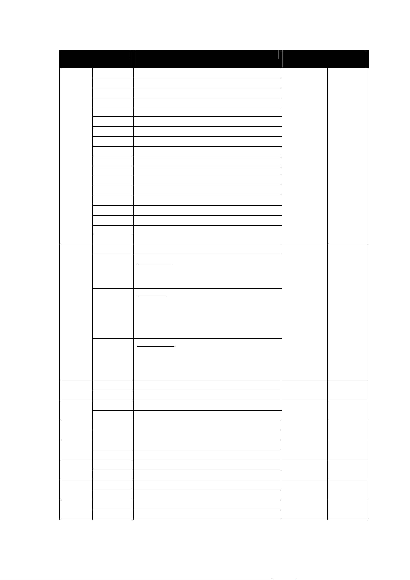
Martin VDO Atomic Dot user guide 45
Extend
ed
Value Function Fade Status Default
Value
131 - 135 Color 25 - Lime Green
136 - 140 Color 26 - Spring Yellow
141 - 145 Color 27 - Deep Amber
146 - 150 Color 28 - Chrome Orange
151 - 155 Color 29 - Orange
156 - 160 Color 30 - Gold Amber
161 - 165 Color 31 - Millennium Gold
166 - 170 Color 32 - Deep Golden Amber
171 - 175 Color 33 - Flame Red
176 - 180 Color 34 - Magenta
181 - 185 Color 35 - Medium Lavender
186 - 190 Color 36 - White
191 - 214
Color Wheel Rotation Fast → Slow
215 - 219 Color Wheel Rotation Stop (stop on last color)
220 - 243
Color Wheel Rotation Inverse Slow → Fast
244 - 247 Random Colors Fast
248 - 251 Random Colors Medium
252 - 255 Random Colors Slow
Aura P3 Mode
0 - 26 DMX-Mode
Color of Aura LEDs is fully controlled by
channel 17-64 (Aura Red, Green & Blue)
(P3 pixels are ignored)
27 - 228 Mix-Mode
Color of Aura LEDs is defined by mix of:
- Channel 17-64 (Aura Red, Green & Blue)
- P3 pixels
(range 27 to 228 performs cross-fade
between the two)
16
229 - 255 Video-Mode
Color and brightness of Aura LEDs is driven
by P3 pixels, but Aura Red/Green/Blue
channels 17-64 keep ability to "color" the
video.
Snap 0
Aura Red Pixel 1
17
0 - 255
0 → 100%
Fade 255
Aura Green Pixel 1
18
0 - 255
0 → 100%
Fade 255
Aura Blue Pixel 1
19
0 - 255
0 → 100%
Fade 255
Aura Red Pixel 2
20
0 - 255
0 → 100%
Fade 255
Aura Green Pixel 2
21
0 - 255
0 → 100%
Fade 255
Aura Blue Pixel 2
22
0 - 255
0 → 100%
Fade 255
Aura Red Pixel 3
23
0 - 255
0 → 100%
Fade 255

46 Martin VDO Atomic Dot user guide
Extend
ed
Value Function Fade Status Default
Value
Aura Green Pixel 3
24
0 - 255
0 → 100%
Fade 255
Aura Blue Pixel 3
25
0 - 255
0 → 100%
Fade 255
Aura Red Pixel 4
26
0 - 255
0 → 100%
Fade 255
Aura Green Pixel 4
27
0 - 255
0 → 100%
Fade 255
Aura Blue Pixel 4
28
0 - 255
0 → 100%
Fade 255
Aura Red Pixel 5
29
0 - 255
0 → 100%
Fade 255
Aura Green Pixel 5
30
0 - 255
0 → 100%
Fade 255
Aura Blue Pixel 5
31
0 - 255
0 → 100%
Fade 255
Aura Red Pixel 6
32
0 - 255
0 → 100%
Fade 255
Aura Green Pixel 6
33
0 - 255
0 → 100%
Fade 255
Aura Blue Pixel 6
34
0 - 255
0 → 100%
Fade 255
Aura Red Pixel 7
35
0 - 255
0 → 100%
Fade 255
Aura Green Pixel 7
36
0 - 255
0 → 100%
Fade 255
Aura Blue Pixel 7
37
0 - 255
0 → 100%
Fade 255
Aura Red Pixel 8
38
0 - 255
0 → 100%
Fade 255
Aura Green Pixel 8
39
0 - 255
0 → 100%
Fade 255
Aura Blue Pixel 8
40
0 - 255
0 → 100%
Fade 255
Aura Red Pixel 9
41
0 - 255
0 → 100%
Fade 255
Aura Green Pixel 9
42
0 - 255
0 → 100%
Fade 255
Aura Blue Pixel 9
43
0 - 255
0 → 100%
Fade 255
Aura Red Pixel 10
44
0 - 255
0 → 100%
Fade 255
Aura Green Pixel 10
45
0 - 255
0 → 100%
Fade 255
Aura Blue Pixel 10
46
0 - 255
0 → 100%
Fade 255

Martin VDO Atomic Dot user guide 47
Extend
ed
Value Function Fade Status Default
Value
Aura Red Pixel 11
47
0 - 255
0 → 100%
Fade 255
Aura Green Pixel 11
48
0 - 255
0 → 100%
Fade 255
Aura Blue Pixel 11
49
0 - 255
0 → 100%
Fade 255
Aura Red Pixel 12
50
0 - 255
0 → 100%
Fade 255
Aura Green Pixel 12
51
0 - 255
0 → 100%
Fade 255
Aura Blue Pixel 12
52
0 - 255
0 → 100%
Fade 255
Aura Red Pixel 13
53
0 - 255
0 → 100%
Fade 255
Aura Green Pixel 13
54
0 - 255
0 → 100%
Fade 255
Aura Blue Pixel 13
55
0 - 255
0 → 100%
Fade 255
Aura Red Pixel 14
56
0 - 255
0 → 100%
Fade 255
Aura Green Pixel 14
57
0 - 255
0 → 100%
Fade 255
Aura Blue Pixel 14
58
0 - 255
0 → 100%
Fade 255
Aura Red Pixel 15
59
0 - 255
0 → 100%
Fade 255
Aura Green Pixel 15
60
0 - 255
0 → 100%
Fade 255
Aura Blue Pixel 15
61
0 - 255
0 → 100%
Fade 255
Aura Red Pixel 16
62
0 - 255
0 → 100%
Fade 255
Aura Green Pixel 16
63
0 - 255
0 → 100%
Fade 255
Aura Blue Pixel 16
64
0 - 255
0 → 100%
Fade 255
Note:
x Fixture will automatically reduce intensity to control temperature when running at high
power for too long
x The Aura pixels are mapped as shown in the diagram below, looking into the fixture lens.

48 Martin VDO Atomic Dot user guide
1
2
3
10
9
8
7
6
5
4
16
15
14
13
11
12
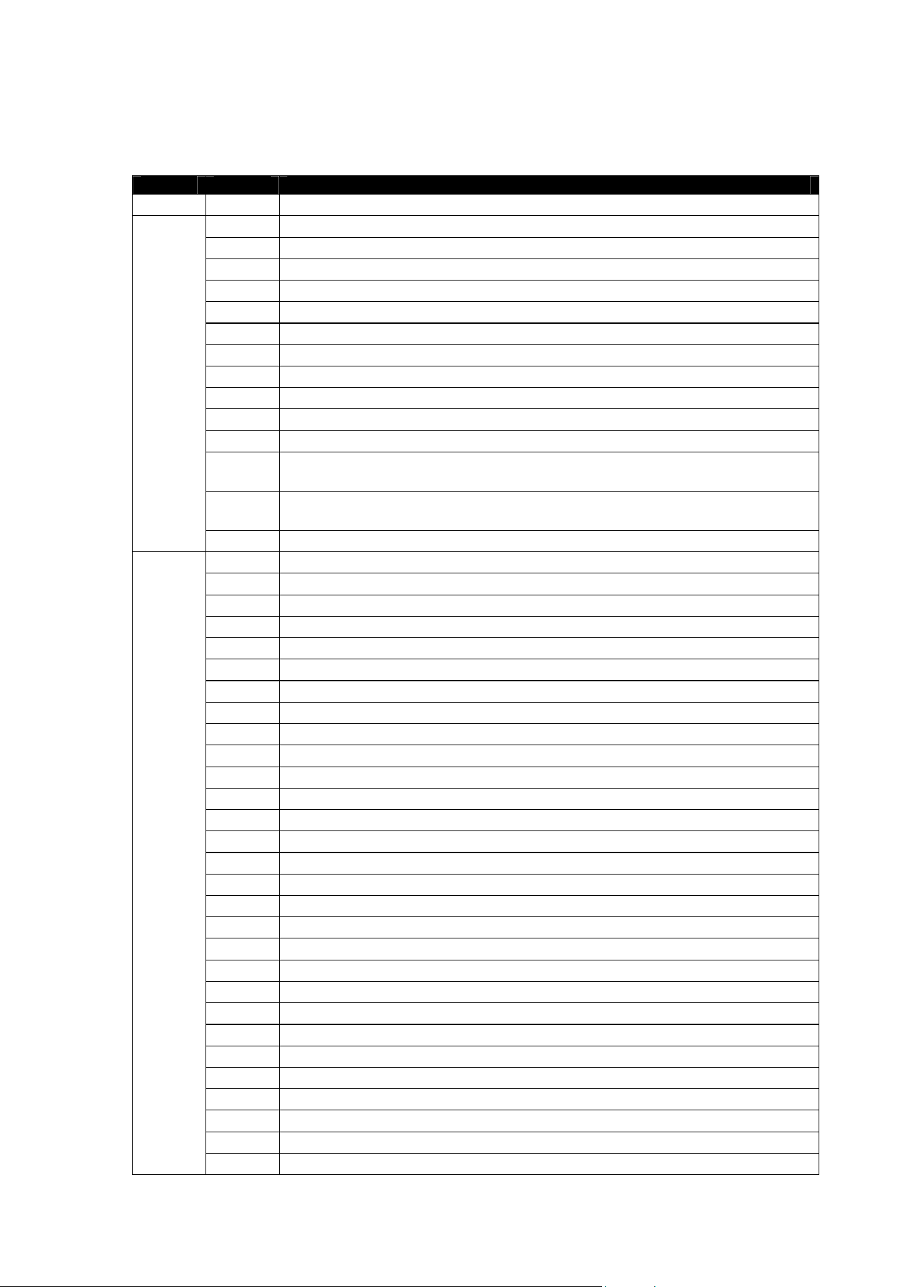
Martin VDO Atomic Dot user guide 49
FX Table
Type DMX FX Name
0 No Effect
1 Beam Wave
2 Beam Step
3 Beam Pulse
4 Beam Blackout Strobe
5 Beam 2x Strobe
6 Beam 3x Strobe
7 Beam 4x Strobe
8 Beam Up, Down Flash
9 Beam Up, Flash, Down, Flash
10 Beam Random Levels
11 Beam HouseLight
12 Beam (strobe) auto-firing when intensity of content hits certain minimum
(threshold set by adjustment channel)
13 Beam threshold effect (Beam lighting up when content above a certain level
which can be set with adjustment channel)
Beam Effects
14-15 No function
16 Aura Wave
17 Aura Step
18 Aura Pulse
19 Aura Blackout Strobe
20 Aura 2x Strobe
21 Aura 3x Strobe
22 Aura 4x Strobe
23 Aura Up, Down Flash
24 Aura Up, Flash, Down, Flash
25 Aura Random Levels
26 Aura Noise Overlay
27 Aura PixelKiller
28 Aura Build Up/Down
29 Aura In-Out Wave
30 Aura In-Out Step
31 Aura In-Out Pulse
32 Aura Waterdrop
33 Aura Sonar (1 pixel)
34 Aura Sonar (2 pixel)
35 Aura Sonar (3 pixel)
36 Aura Sonar (6 pixel)
37 Aura Sonar (9 pixel)
38 Aura Slice Pie chase
39 Aura Random Chase
40 Aura Movie Flicker
41 Aura Electric Arc
42 Aura Atomic Lighting
43 Aura Thunderstorm
Aura Intensity Effects
44-47 No function

50 Martin VDO Atomic Dot user guide
Type DMX FX Name
48 Aura Rainbow Wave
49 Aura Rainbow Step
50 Aura Rainbow Pulse
51 Aura RGB Wave
52 Aura RGB Step
53 Aura RGB Pulse
54 Aura CMY Wave
55 Aura CMY Step
56 Aura CMY Pulse
57 Aura Random Mix Wave
58 Aura Random Mix Step
59 Aura Random Mix Pulse
60 Aura Solid
61 Aura Spectrum Shifter
62 Aura RGB to White Wave
63 Aura RGB to White Step
64 Aura RGB to White Pulse
65 Aura RGB to White Strobe
66 Aura Normal to White Wave
67 Aura Normal to White Step
68 Aura Normal to White Pulse
69 Aura Normal to White Strobe
70 Aura RGB to Inverted Color In/Out Wave
71 Aura RGB to Inverted Color In/Out Step
72 Aura RGB to Inverted Color In/Out Pulse
73 Aura Normal to Inverted Color In/Out Wave
74 Aura Normal to Inverted Color In/Out Step
75 Aura Normal to Inverted Color In/Out Pulse
Aura Color Effects
76-79 No function
80 Aura Red white blue fade
81 Aura Red white blue snaps
82 Aura Fire
83 Aura Water
84 Aura Ice
85 Aura Hot and cold
86 Aura Warm and fuzzy
87 Aura Silver and gold
88 Aura Gold and silver
89 Aura NightRider
90 Aura Police car 1
91 Aura Police car 2
92 Aura Police car 3
93 Aura Swimming pool
94 Aura Electric arc
95 Aura Stars
96 Aura Fiberoptic White
97 Aura Fiberoptic Mix
Aura Complete Effects
98 Aura Plasma
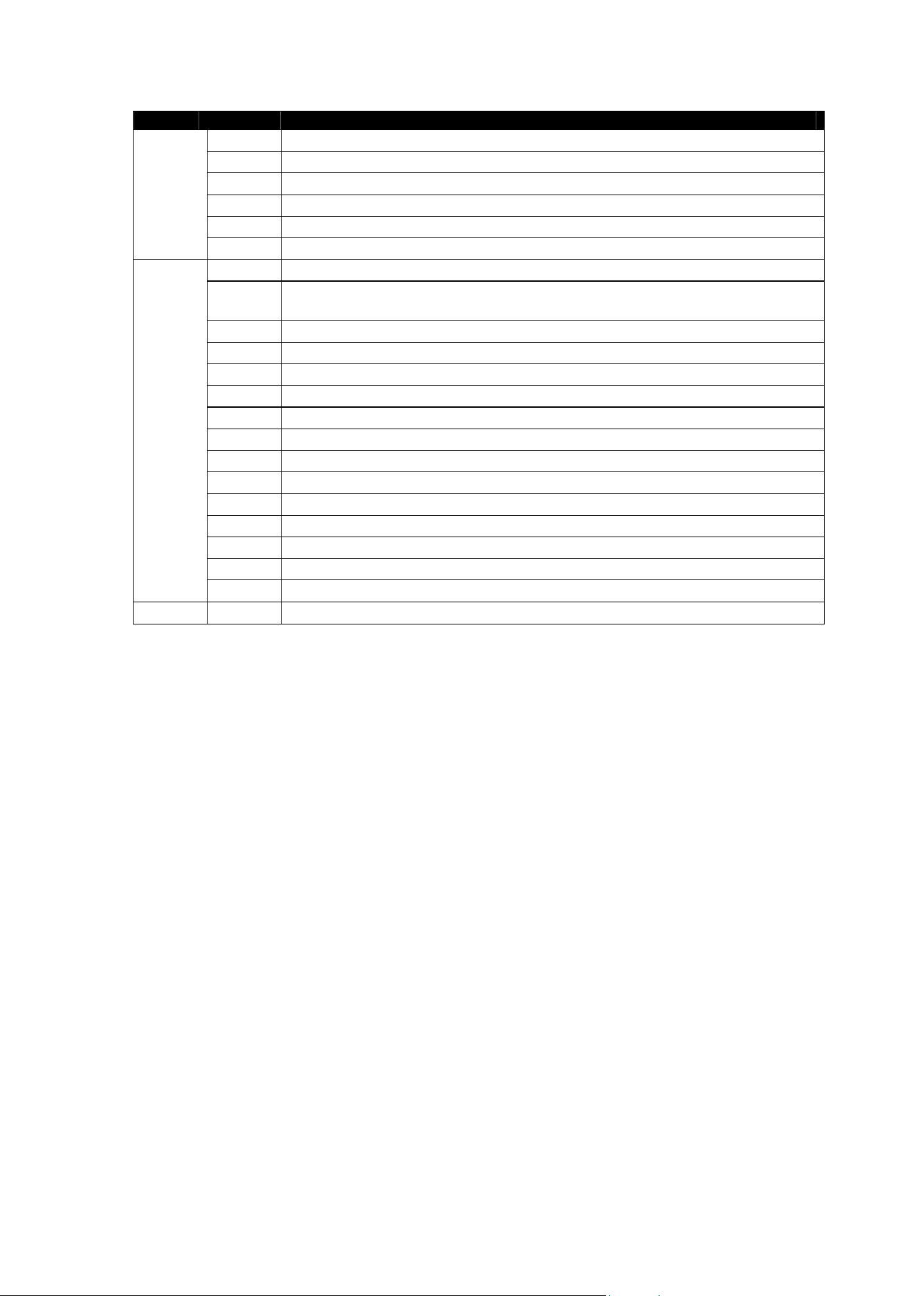
Martin VDO Atomic Dot user guide 51
Type DMX FX Name
99 Aura Starfield
100 Aura Colorwave
101 Aura Noise
102 Aura Snowflakes
103 Aura Rain
104-111 No function
112 Tungsten Emulation using Aura backlight to complement main beam
113 Tungsten Emulation using Aura backlight to complement main beam,
including decay
114 Thunderstorm
115 Welding
116 3 Step strobe
117 Tick Tock
118 Aura ramp beam flash
119 Beam ramp aura flash
120 Police Car 4
121 Police Car 5
122 Police Car 6
123 Police Car 7
124 Police Car 8
125 Police Car 9
Beam+Aura Combined Effects
126-254 No function
255 PWM frequency adjustment
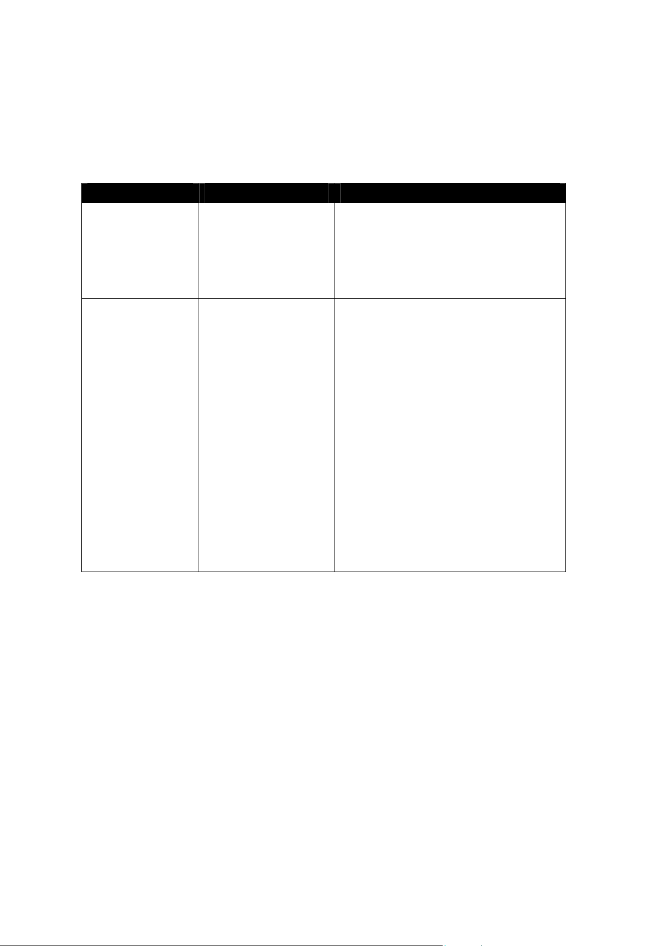
52 Martin VDO Atomic Dot user guide
Troubleshooting
This section describes a few common problems that may occur during operation and provides
some suggestions for easy troubleshooting:
Symptom Potential cause Remedies
No light from fixture. Power supply issue,
such as blown fuse,
faulty connector or
damaged cable.
Ensure that the mains supply is connected
to the junction box and supplying power to
the fixture.
Ensure that the fixture’s test LED lights up
when the test button is pressed.
Check all power connections and cables.
Fixture does not
respond to control.
Fault in the control
network due to wiring
problem, connector or
cable damaged, or
incorrect DMX
addressing, or
potential interference
from proximity to a high
voltage installation.
Check if the fixture status LED is flashing
red to show that control data is not being
received, and if so, check all DMX cables
and connections to ensure the integrity of
the physical network.
Ensure that the DMX network is terminated.
Check that the components in the DMX
network all use standard DMX polarity.
Ensure that the fixture is set to the correct
DMX address, one that matches that set on
the DMX control device.
Check the pins on the connectors from the
previous fixture in the DMX network.
Attempt to control the fixture with another
DMX control device.
Move the fixture if it is being operated very
close to an unshielded high-voltage
installation.
Martin VDO Atomic Dot user guide 53
Disposing of this product
Martin™ products are supplied in compliance with Directive 2012/19/EC of the European
Parliament and of the Council of the European Union on WEEE (Waste Electrical and
Electronic Equipment), where applicable. Help preserve the environment! Ensure that
this product is recycled at the end of its life. Your supplier can give details of local
arrangements for the disposal of Martin products
FCC Compliance
This device complies with Part 15 of the FCC Rules. Operation is subject to the following two conditions: (1) This
device may not cause harmful interference, and (2) this device must accept any interference received, including
interference that may cause undesired operation.
Note: This equipment has been tested and found to comply with the limits for a Class B digital device, pursuant to
part 15 of the FCC Rules. These limits are designed to provide reasonable protection against harmful interference
in a residential installation. This equipment generates, uses and can radiate radio frequency energy and, if not
installed and used in accordance with the instructions, may cause harmful interference to radio communications.
However, there is no guarantee that interference will not occur in a particular installation. If this equipment does
cause harmful interference to radio or television reception, which can be determined by turning the equipment off
and on, the user is encouraged to try to correct the interference by one or more of the following measures:
—Reorient or relocate the receiving antenna.
—Increase the separation between the equipment and receiver.
—Connect the equipment into an outlet on a circuit different from that to which the receiver is connected.
—Consult the dealer or an experienced radio/TV technician for help.
Supplier’s Declaration of Conformity
Harman Professional, Inc. have issued an FCC Supplier’s Declaration of Conformity for this product. The
Declaration of Conformity is available for download from the VDO Atomic Dot area of the Martin website at
www.martin.com
Canadian Interference-Causing Equipment Regulations - Règlement sur le Matériel Brouilleur du Canada
This Class B digital apparatus meets all requirements of the Canadian Interference-Causing Equipment
Regulations CAN ICES-3 (B)/NMB-3(B) and CAN ICES-005 (B) / NMB-005 (B).
Cet appareil numérique de la classe A respecte toutes les exigences du Règlement sur le Matériel Brouilleur du
Canada.
EU EMC
Not for use in a computer room as defined in the Standard for the Protection of Information Technology Equipment,
ANSI/NFPA 75.
Ne peut être utilisé dans une salle d'ordinateurs telle que définie dans la norme ANSI/NFPA 75 Standard for the
Protection of Information Technology Equipment.
Photobiological Safety Warning
The label shown below is displayed on the CLD version of this product. If it becomes difficult or
impossible to read, it must be replaced using the illustration below to reproduce new labels sized
17 x 51 mm, in black on a yellow background.

www.martin.com · Olof Palmes Allé 44 · 8200 Aarhus N · Denmark
Tel. +45 8740 0000 · Fax +45 8740 0010
Harman Professional Solutions · 8500 Balboa Blvd· Northridge
CA 91329 · United States
