1
© Copyright 2024 Zoeller
®
Co. All rights reserved.
Product information presented here reflects conditions at time of publication. Consult factory regarding discrepancies or inconsistencies.
MAIL TO: P.O. BOX 16347 • Louisville, KY 40256-0347
SHIP TO: 3649 Cane Run Road • Louisville, KY 40211-1961
Tel: (502) 778-2731 • 1 (800) 928-PUMP
Visit our website:
zoellerpumps.com
Trusted. Tested. Tough.
®
Congratulations on the purchase of the Zoeller submersible
grinder pump. Since 1939, the name Zoeller
®
has represented the
standard for submersible dewatering and sewage pumps. The same
high quality workmanship and easy maintenance design has been
incorporated into this line of heavy-duty submersible grinder pumps.
This Zoeller
®
pump will provide years of trouble-free service when
installed according to the manufacturer’s recommendations.
This manual incorporates the installation, operation,
maintenance, and service instructions into one document to aid
in the ownership of a Zoeller
®
submersible wastewater product.
Model Number: _____________Date Code: _______________
Automatic Nonautomatic
Packaged System Field Assembled System
Job Name: ___________________________________________
Distributor: ____________________________________________
Date of Purchase: _______ Zoeller S/O No.: ______________
Contractor: ____________________________________________
Date of Installation: ____________________________________
System Readings During Start-up: Voltage _____
Amps ______
OWNER’S MANUAL
MODELS 818 & 820 SUBMERSIBLE GRINDER UNITS
Please read and review this manual before installing the product.
Follow the steps in this manual for a proper start-up. Many items
contained within, when followed correctly, will not only ensure a
long and problem-free life for the pump, but also save time and
money during installation. For replacement parts lists, please
reference FM2993 for 818 series, and FM1531 for 820 series.
Should further assistance be necessary please call our Product
Support Department at 1-800-928-PUMP (7867).
Owner’s Information
Table of Contents
Safety Instructions ..........................................................................1
Limited Warranty.............................................................................2
Preinstallation Checklist .................................................................3
General Information ........................................................................ 4
Pump Wiring Instructions ...............................................................5
Typical Indoor Prepackaged System .............................................6
Indoor Prepackaged Installation Instructions ...............................7
Typical Outdoor Prepackaged System .......................................... 8
Outdoor Prepackaged Installation Instructions............................9
Operation .......................................................................................10
Cutter Maintenance.......................................................................11
Service Checklist ...........................................................................12
Safety Instructions
TO AVOID SERIOUS OR FATAL PERSONAL INJURY OR MAJOR
PROPERTY DAMAGE, READ AND FOLLOW ALL SAFETY
INSTRUCTIONS IN THIS MANUAL AND ON THE PUMP.
THIS MANUAL IS INTENDED TO ASSIST IN THE
INSTALLATION AND OPERATION OF THIS UNIT AND MUST
BE KEPT WITH THE PUMP.
This is a SAFETY ALERT SYMBOL.
When you see this symbol on the pump or in the
manual, look for one of the following signal words
and be alert to the potential for personal injury or
property damage.
Warns of hazards that WILL cause serious personal
injury, death or major property damage.
Warns of hazards that CAN cause serious personal
injury, death or major property damage.
Warns of hazards that CAN cause personal injury
or property damage.
INDICATES SPECIAL INSTRUCTIONS WHICH ARE
VERY IMPORTANT AND MUST BE FOLLOWED.
THOROUGHLY REVIEW ALL INSTRUCTIONS AND
WARNINGS PRIOR TO PERFORMING ANY WORK ON THIS
PUMP.
MAINTAIN ALL SAFETY DECALS.
PUMPS WITH THE “UL” MARK AND PUMPS WITH THE
“US” MARK ARE TESTED TO UL STANDARD UL778. CSA
CERTIFIED PUMPS ARE CERTIFIED TO CSA STANDARD
C22.2 NO. 108.
CAUTION
REFER TO WARRANTY ON PAGE 2.
FM2167
1224
Supersedes
0924
P/N 019555
Register your
Zoeller Pump Company
Product on our website:
http://reg.zoellerpumps.com/
Tested to UL778 and
cCSAus 22.2 108
Standards.
®
TM

2
© Copyright 2024 Zoeller
®
Co. All rights reserved.
LIMITED WARRANTY
1. Zoeller Grinder Pumps are designed for grinding and pumping sanitary
sewage from submersible lift stations. The pump is intended to grind and pump
reasonable quantities of items normally found in sanitary sewage applications.
2. Zoeller Grinder Pumps can be installed in new applications or as a direct
replacement for any grinder application of like size and capacity. Some rail
system retrot kits are available.
3. Zoeller Grinder Pumps can be installed in a prepackaged job ready system
or may be used in a eld assembled basin package.
4. Zoeller Grinder Pumps can be retrotted to existing positive displacement
pump installations.
Applications
Contact Manufacturer at, 3649 Cane Run Road, Louisville, Kentucky 40211, Attention:
Customer Support Department to obtain any needed repair or replacement of
part(s) or additional information pertaining to our warranty.
MANUFACTURER EXPRESSLY DISCLAIMS LIABILITY FOR SPECIAL,
CONSEQUENTIAL OR INCIDENTAL DAMAGES OR BREACH OF EXPRESSED
OR IMPLIED WARRANTY; AND ANY IMPLIED WARRANTY OF FITNESS FOR A
PARTICULAR PURPOSE AND OF MERCHANTABILITY SHALL BE LIMITED TO THE
DURATION OF THE EXPRESSED WARRANTY.
Some states do not allow limitations on the duration of an implied warranty, so
the above limitation may not apply to you. Some states do not allow the exclusion
or limitation of incidental or consequential damages, so the above limitation or
exclusion may not apply to you.
This warranty gives you specic legal rights and you may also have other rights
which vary from state to state.
Manufacturer warrants, to the purchaser and subsequent owner during the
warranty period, every new product to be free from defects in material and
workmanship under normal use and service, when properly used and maintained,
for a period of three years from the date of purchase. Proof of purchase is required.
Parts that fail within the warranty period, that inspections determine to be defective
in material or workmanship, will be repaired, replaced or remanufactured at
Manufacturer's option, provided however, that by so doing we will not be obligated
to replace an entire assembly, the entire mechanism or the complete unit. No
allowance will be made for shipping charges, damages, labor or other charges
that may occur due to product failure, repair or replacement.
This warranty does not apply to and there shall be no warranty for any material
or product that has been disassembled without prior approval of Manufacturer,
subjected to misuse, misapplication, neglect, alteration, accident or act of
nature; that has not been installed, operated or maintained in accordance with
Manufacturer's installation instructions; that has been exposed to outside
substances including but not limited to the following: sand, gravel, cement, mud,
tar, hydrocarbons, hydrocarbon derivatives (oil, gasoline, solvents, etc.), or other
abrasive or corrosive substances, wash towels or feminine sanitary products, etc.
in all applications other than raw sewage pumping applications. The warranty
set out in the paragraph above is in lieu of all other warranties expressed or
implied; and we do not authorize any representative or other person to assume
for us any other liability in connection with our products.
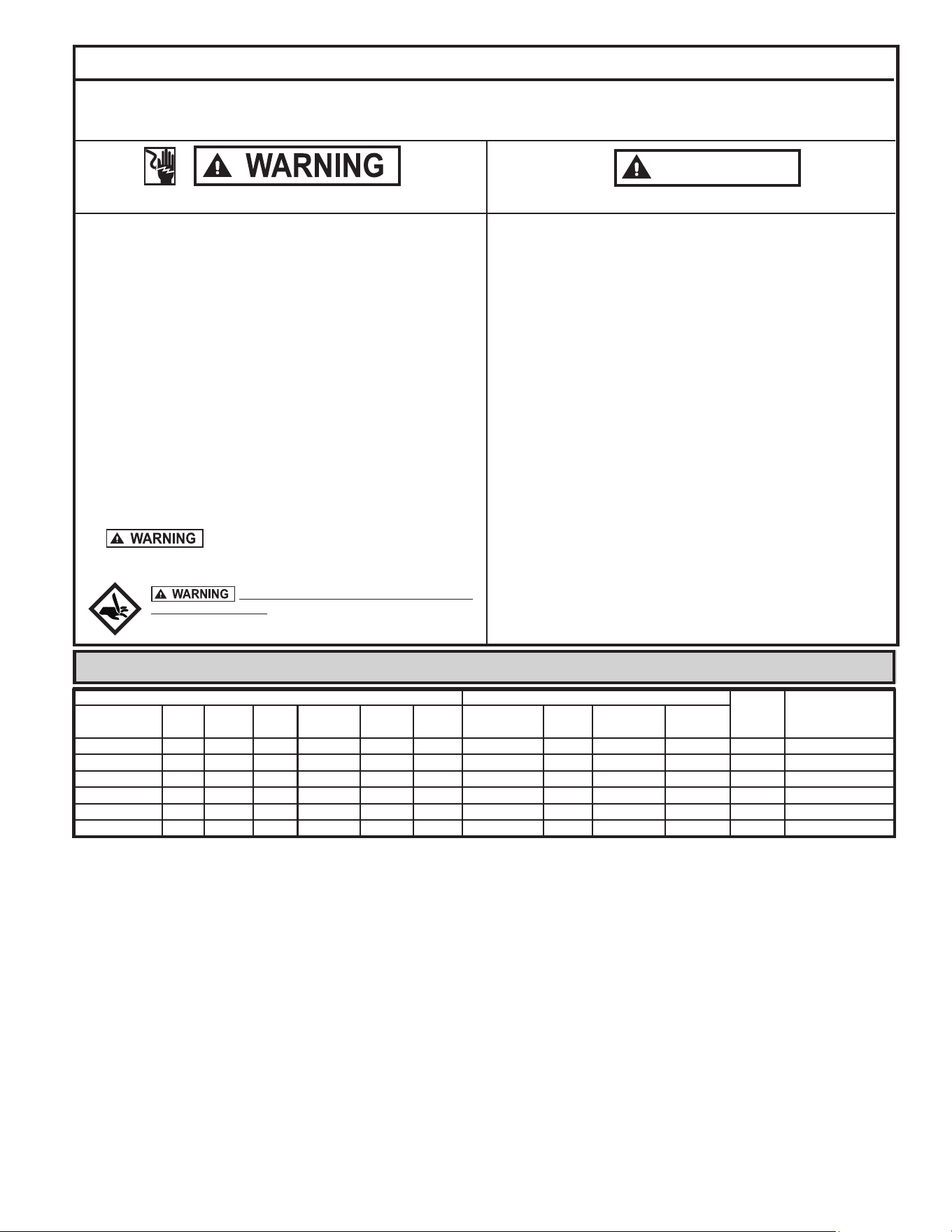
*Zoeller Company does not recommend a simplex station on anything over two homes in order to maintain continuous service during unusual conditions.
Recommended Limits of Application 800 Series Grinder Pumps
These recommended application limits are for pump stations pumping to a gravity main. Low-pressure pipe systems should be designed with a pump located at
each house. For applications where a lift station would handle between 15 and 60 homes, consider the 71 Series grinder pump. For applications where a lift station
would handle more than 60 homes, a solids handling type pump should be considered.
Simplex Station Duplex Station
Model HP Homes GPD Homes GPD
810 Progressing Cavity Grinder 1.0 1 4,176 2 8,352
815 Progressing Cavity Grinder 2.0 1 4,176 2 8,352
818 1.0 1 12,384 2 24,768
820 2.0 1 13,248 2 26,496
840 w/ Reversing Control 2.0 2* 12,960 15 25,920
841 2.0 2* 15,840 10 31,680
In instances where property damages are incurred as a result of an alleged product failure,
the property owner must retain possession of the product for investigation purpose.
3
© Copyright 2024 Zoeller
®
Co. All rights reserved.
Preinstallation Checklist
1. Inspect your grinder pump. If the unit has been damaged in shipment, contact
your dealer before installing. Do Not remove the test plug in the cover nor the
motor housing.
2. Carefully read all literature to familiarize yourself with details regarding
installation and use. Retain materials for future reference.
1. Make sure pump connection contains a ground terminal. The power cord on
all Zoeller Grinder Pumps contains a green conductor for grounding to help
protect you against the possibility of electric shock.
2. Make certain the receptacle is within reach of the power supply cord.
3. Make sure any panels and branch circuits are equipped with proper size fuses
and circuit breakers. An independent power circuit is recommended, sized
according to the National Electrical Code, for the current shown on the grinder
pump nameplate.
4. Automatic pumps have three prong plug caps and must be connected to a three
prong grounded receptacle with ground fault circuit interrupter (GFCI).
5. For your protection, always disconnect the power source to the grinder pump
before handling. All grinder pumps must be properly grounded and wired
in accordance with the “National Electrical Codes” and all local codes and
ordinances.
6. Installation of electrical hardware and checking of control panels and circuits
should be performed by a qualied licensed electrician.
7. Risk of electrical shock - These pumps have not been investigated for use in
swimming pool areas.
8. Prop65 Warning for California residents:
: Cancer and Reproductive Harm-
www.P65Warning.ca.gov.
SEE BELOW FOR LIST OF WARNINGS
CAUTION
SEE BELOW FOR LIST OF CAUTIONS
Do not attempt to turn cutter located on bottom
of the unit with ngers. Use a wrench when checking or remov-
ing cutter.
1. Make sure the power source is capable of handling the electrical requirements
of the grinder pump, as indicated on the nameplate.
2. A disconnect switch should be installed ahead of the pump.
3. If Grinder pumps are operated by control panels with variable level oat
control switches, it is the responsibility of the installing party that oat control
switches will not hang up on the grinder pump or other pit peculiarities and
are secured so that the grinder pump will shut off. It is recommended to use
rigid pipe and ttings and the pit be 24" in diameter for simplex systems and
36" in diameter for duplex systems or larger.
4. Grinder installations should be checked yearly for debris and/or build up which
may interfere with the “ON” or “OFF” positions of variable level oat control
switches. Repair and service, other than cutter assembly maintenance, should
be performed by Zoeller Engineered Products authorized service stations only.
5. Maximum operating temperature must not exceed 130 °F, (54 °C).
6. Pump and oat switch electrical connections must be permanently installed,
operational and protected from submergence.
7. Junction box conduit must be installed with watertight connection. Zoeller
junction boxes include a UL Listed potting kit for sealing conduit. Failure to
properly install this sealant material could void warranty.
Electrical Data
Amps
KVA
Code
Winding
Resistance
Line-to-Line
Model HP Mode RPM Voltage Phase Hertz Full Load In Air Shut Off
Locked
Rotor
WM818 1 Auto 3450 115 1 60 13.6 8.0 10.2 46 F 0.67 / 3.4
N818 1 Non 3450 115 1 60 13.6 8.0 10.2 46 F 0.67 / 3.4
EI818 1 Non 3450 200-230 1 60 9.9 (8.6)* 5.3 (7.6)* 46 (57)* L (P)* 1.2 / 2.0
WDH818 1 Auto 3450 200-230 1 60 9.9 (8.6)* 5.3 (7.6)* 46 (57)* L (P)* 1.2 / 2.0
EI820 2 Non 3450 200 - 230 1 60 14.5 (13.7)* 9.6 (10.2)* 46 (57)* E (H)* 1.2 / 2.0
WDH820 2 Auto 3450 200 - 230 1 60 14.5 (13.7)* 9.6 (10.2)* 46 (57)* E (H)* 1.2 / 2.0
* DENOTES ELECTRICAL VALUES AT HIGHER VOLTAGE RANGE.
4
© Copyright 2024 Zoeller
®
Co. All rights reserved.
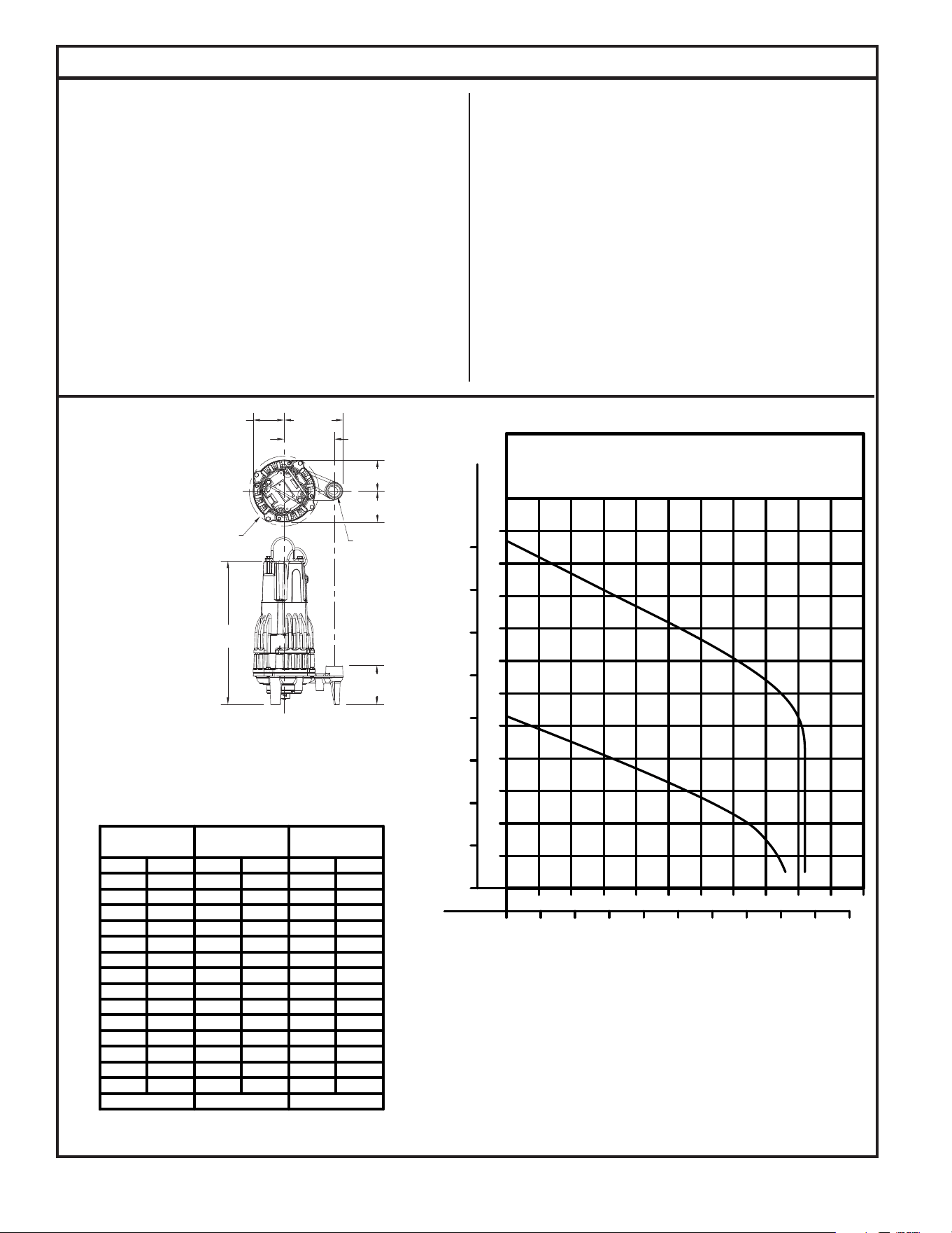
1-1/4" N.P.T.
18-9/16"
[472 mm]
5"
[127 mm]
4" [102 mm]
4" [102 mm]
4"
[102 mm]
7-5/8"
[194 mm]
6-1/2"
[165 mm]
ø9-1/16"
[ø230 mm]
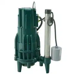
General Information
GRINDER PUMP DESCRIPTION
1. Pumps are constructed of cast iron with powder coated epoxy protection
for long life when pumping sewage in submersible applications. The cutter
assembly is comprised of 440 C stainless steel components hardened to a
value of 55-60 on the Rockwell C scale; a cutter and a precision ground at
disk. Cutting action takes place with the rotation of the cutter in the clockwise
(looking down on the unit) direction only, see Fig. 6 on page 11.
2. Pump motors are available in single and three phase design. Single phase
motors require a starting relay, starting capacitor and a run capacitor. Single
phase models with remotely mounted starting components are available.
These units are identiable by a 4 conductor cord without a plug cap.
3. These grinder pumps have a single seal design and do not have sensor wires.
4. Automatic reset thermal overload protection is integral on single phase motors.
For three phase models, overload protection is to be provided in the control
panel.
FIELD ASSEMBLED INSTALLATION
1. Installation and piping instructions are included with the rail system and
basin instructions. If pump is being retrotted to an existing rail system,
accessory parts may be required. Consult the factory and advise make and
model of rail system being used.
2. Refer to the appropriate Indoor/Outdoor prepackaged instructions on pages
6-9 for more information on system installation.
3. All electrical connections including pump to control box and power supply
to control panels must comply with the “National Electrical Code” and ap-
plicable local codes. Conduit and panel enclosure openings must have a
gas and watertight seal. Installation of electrical panels, conduit and con-
nections should be made by a qualied licensed electrician. A UL Listed
potting kit, P/N 10-2350, is available from Zoeller Company.
4. When installing a pump with a check valve, or a rail system with a check
valve, you must give the pump case time to ll to help prevent air lock when
lowering the unit into the liquid. The pump case has an air vent located
behind the discharge. This air vent is across the pump housing mounting
surface and must be cleaned before each reinstall. An extra air vent hole
(3/16") may be drilled in discharge pipe below the check valve to help prevent
air lock. This drilled hole must be cleaned before each reinstall. After the
pump is installed, run the unit submerged to assure the pump case is lled
(Water should come out of 3/16" diameter hole).
SK1621
FIGURE 1.
154108
154108
Shut-o Head:
90
100
80
70
53 ft. (16.2m)
27.4
30.5
24.4
21.3
-
-
-
-
MODEL
60
50
40
30
20
10
5
Feet
-
-
16.5
28
37
42
15.2
18.3
12.2
6.1
9.1
3.0
-
-
62
140
106
159
43
Gal.
1.5
Meters
820
Liters
163
TOTAL DYNAMIC HEAD/FLOW
PER MINUTE
SEWAGE AND DEWATERING
Gal.
818
Liters
-
-
-
-
16.7
27
36
107 ft. (32.6m)
7
63
26
102
136
43
46
46
46
46
46
174
163
174
174
174
174
46 174
15 40
35
25 33
4.6
7.6
10.7
151
125
8322
46 174
46 174
46 174
20
30
40
50
60
10
15
20 25
30 35
40 45
50
555
20 40
60 80 100 120 140 160 180 200
0
METERS
FEET
PUMP PERFORMANCE CURVE
MODELS 818/820
0
TOTAL DYNAMIC HEAD
FLOW PER MINUTE
U.S. GALLONS
LITERS
70
10
80
90
100
110
4
8
12
16
20
24
28
32
820
818
5
© Copyright 2024 Zoeller
®
Co. All rights reserved.
MIN. "OFF" LEVEL
22" MAX.
5" MIN.
20 AMP SWITCH (WD & WH MODELS)
FOR YOUR PROTECTION, ALWAYS DISCONNECT THE PUMP FROM ITS POWER SOURCE BEFORE HANDLING. Single phase
automatic pumps are supplied with a 3-prong grounded plug to help protect you against the possibility of electrical shock. DO NOT UNDER
ANY CIRCUMSTANCES REMOVE THE GROUND PIN. The 3-prong plug must be inserted into a mating 3-prong grounded receptacle. If the
installation does not have such a receptacle, it must be wired and grounded in accordance with the National Electrical Code and all applicable
local codes and ordinances.
“Risk of electrical shock” Do not remove the power supply cord and strain relief or connect conduit directly to pump.
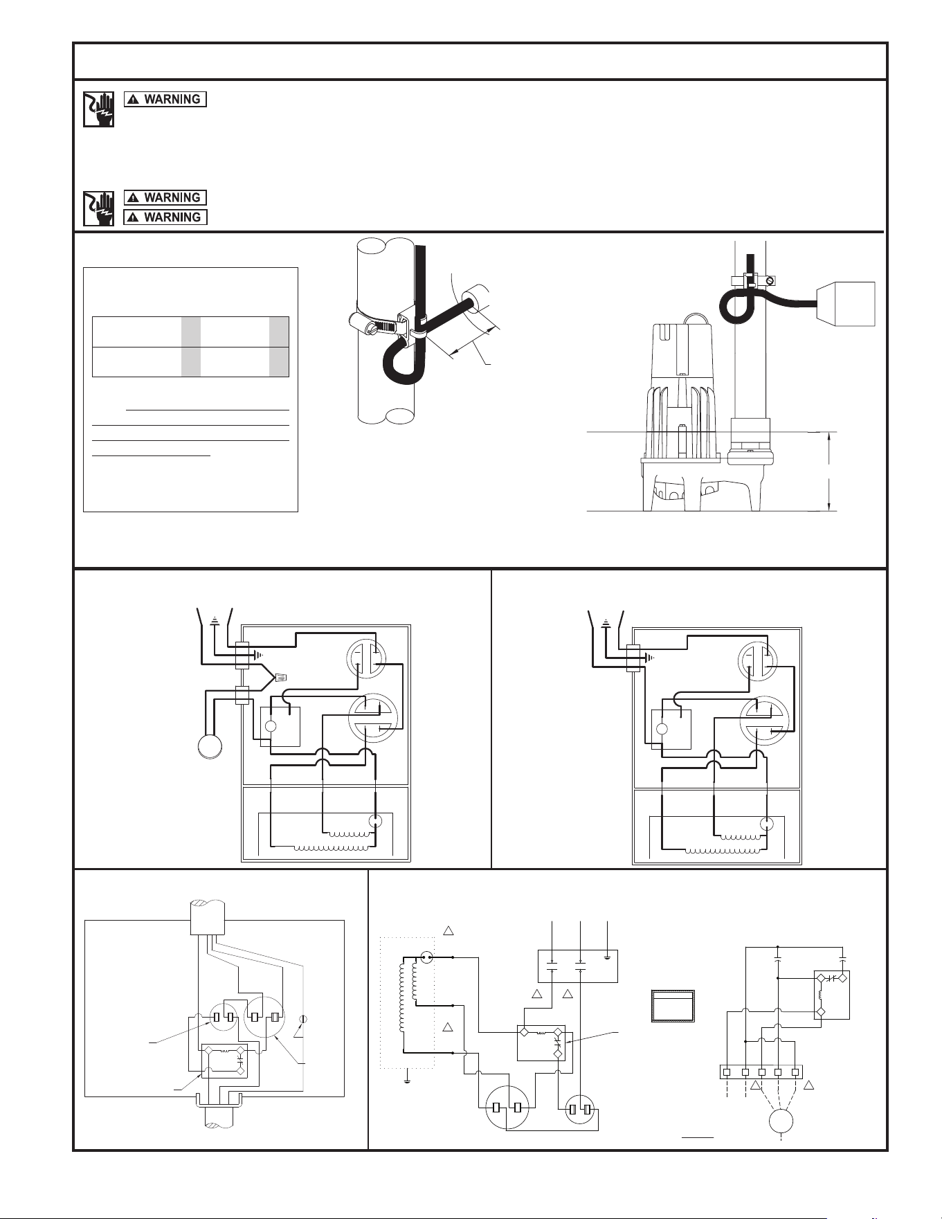
Pump Wiring Instructions
Installation and checking of electrical circuits and hardware should be performed by a qualied licensed electrician.
FIGURE 4.
FIGURE 5.
Models WDH & WM are fully automatic. A oat switch is included and factory wired in the pump circuit to provide automatic operation once the oat switch is
secured properly to the outlet pipe. Use the diagram above to secure the oat switch properly and obtain the proper tether to customize the on-off cycle to each
application. Note the minimum off level shown above. On Prepackaged Systems, the tether length is set at 5”.
Determining Pumping Range
in Inches (1 inch - 2.5 cm)
Tether Length 5 10 15 20 22
Pumping Range 9 13.5 18 22 24
Use only as a guide. Due to weight of
cable, pumping range above horizontal
is not equal to pumping range below
horizontal. Ranges are based on testing in
nonturbulent conditions. Range may vary
due to water temperature and cord shape.
As tether length increases, so does the
variance of the pumping range.
Note: Failure to keep within proper tether limits may
prevent reliable switch operation.
Note: Cable must be mounted in horizontal position.
SK2304
min.
max.
SK305D
RUN
O.L.
MOTOR
(3)
BLUE
RED
BLACK
GREEN
L1
L2
START
(1)
(2)
YELLOW
RED
R
RELAY
(WHITE) (BLACK)
YELLOW
(BROWN)
BLUE
1
5
2
WHITE
CAPACITOR
START
WHITE
BLACK
BLACK
CAPACITOR
RUN
RUN
O.L.
MOTOR
(3)
BLUE
RED
FLOAT
BLACK
GREEN
L1
L2
START
(1)
(2)
YELLOW
RED
R
RELAY
(WHITE) (BLACK)
YELLOW
CAPACITOR
(BROWN)
BLUE
WHITE
1
5
2
BLACK
WHITE
CAPACITOR
START
RUN
BLACK
WHITE
BLACK
010415
AUTOMATIC
WIRING DIAGRAM
010443
NONAUTOMATIC
WIRING DIAGRAM
1 PH
2
1
5
START RELAY
START CAPACITOR
L1 L2
RUN CAPACITOR
GROUND SCREW
BLACK
WHITE
RED
GREEN
14-4
LEAD IDENTIFICATION
B B
BB
C
C
COMPONENT LAYOUT
START RELAY
START CAPACITOR
RUN CAPACITOR
BLACK
WHITE
L1
L2
T2
T1
230V AC
OR
208V AC
CONTACTOR
COLOR CODING FOR
ZOELLER PUMPS ONLY!
INCORRECT WIRING WILL
CAUSE SEVERE DAMAGE
TO PUMP AND PANEL
WARNING!
CHECK VOLTAGE OF
PUMP BEFORE WIRING.
SC-START CAPACITOR
RC-RUN CAPACITOR
SR-START RELAY
LEGEND:
2
1
5
RED
WHT
BLK
(SEE NOTE 4)
L1 L2
PUMP
GROUND
1
2
3 4
5
RC
TB1
SC
SR
2
1
5
RUN
O.L.
RED
START
YELLOW
(BLACK)
(BROWN)
BLUE
(WHITE)
NONAUTOMATIC WIRING DIAGRAM
1 PH w/REMOTE START COMPONENTS
SK3412
158390
6
© Copyright 2024 Zoeller
®
Co. All rights reserved.
SK1691A
SK1691B
All installations must comply with all applicable electrical and plumbing codes, including but not limited to the National Electrical
Code, local, regional and/or state plumbing codes, etc.
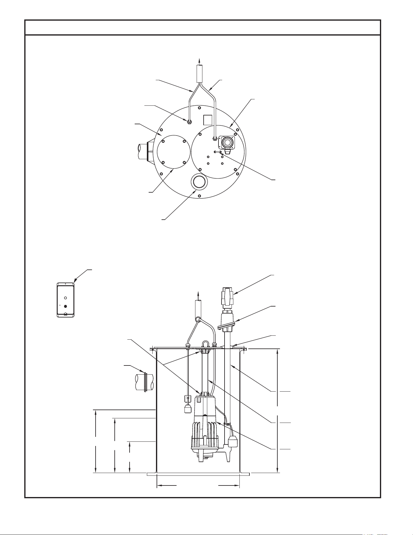
Indoor Prepackaged System
FIGURE 2.
TO ALARM PANEL
24" X 1/4" STEEL
(VENT CONNECTION)
10" X 1/4" STEEL
CORD SEAL
INSPECTION PLATE
3" GROMMET SEAL
SWITCH CORD
ALARM FLOAT
BASIN COVER
LIFTING BOLT
16" X 1/4" STEEL
5/16" 304 STAINLESS STEEL
PUMP PLATE
PUMP POWER CORD
SILENCE
INPUT 1
POWER
ON
(FIELD INSTALLED)
ALARM
4" RUBBER INLET
CAST IRON ADAPTERS
OFF
24" NOMINAL
TO ALARM PANEL
BALL VALVE
(FIELD INSTALLED)
GALVANIZED PIPE
1-1/4" X 32"
GALVANIZED PIPE
1-1/4" X 12"
GRINDER PUMP
SINGLE PHASE,2HP
1-1/4" GROMMET SEAL
(FIELD INSTALLED)
CAST IRON CHECK VALVE
1-1/4" FEMALE NPT
AUTOMATIC
36"
1-1/4" PVC SLIP X SLIP
HIGH WATER ALARM
(FIELD INSTALLED)
PIPE SEAL

7
© Copyright 2024 Zoeller
®
Co. All rights reserved.
Indoor Prepackaged System Installation Instructions
This set of instructions is for factory prepackaged indoor systems only. If your system is a eld assembled
indoor system, use these instructions as a guideline. If your system is an outdoor system then go to the next section in this manual
that covers outdoor systems.
1. Indoor grinder pump systems are for installing at grade in an
indoor application only. If you will be installing this system
outside next to the residence then you will need an outdoor
system. DO NOT INSTALL THE INDOOR SYSTEM OUTDOORS.
2. Review the drawing in Fig. 2 on page 6 and the actual system
to become familiar with the components in the grinder pump
system. Review where the unit will be installed. Determine
where the power feed, inlet pipe, discharge pipe and vent
will be located.
3. Remove the unit from the packing. Indoor prepackaged
systems are preassembled at the Zoeller Company and require
a minimum of eld assembly work. All work inside the basin
can be performed via the inspection port. There should be
no reason to remove the cover from the basin. Pump and
oat switches are already set inside the basin.
4. Remove the inspection plate from the cover. All oats are set
and tethered for proper operation from the factory. Verify that
where the oat switches are set will work for your application.
Verifying that the oat switches are set properly and will not
hang up inside the basin is the responsibility of the installing
contractor. Float switches are tied in place for shipping
purposes. Cut the cable tie around each oat switch bulb
or the unit will not operate properly.
5. Dig a hole for the basin. The basin should be located in a
very low trafc area within 15’ of the power disconnect.
The hole should be at least 8” larger in diameter than the
basin in order to leave 4” of backll all the way around
the perimeter. A minimum of 4” of compacted subbase
is also required. Backll and subbase should be 1/8” to
3/4” pea gravel or 1/8” to 1/2” crushed stone. Also reference
the basin installation instructions included with the unit.
6. The 4” inlet hub should be located between the top lip of
the basin and the alarm oat “on” level with a minimum
distance of 10 inches between the oor of the basin and hub.
Determine the location of the inlet hub based upon your inlet
pipe arrangement. The inlet hub must be used with 4” pipe.
It is best to install the inlet on the side of the basin opposite
the oat switches. To install, use a 4” hole saw to drill into
the side of the basin at the correct elevation. Center the
hub inner diameter with the hole in the basin. Attach the
hub to the side of the basin using the sealant and hardware
provided.
7. Set the basin in the hole and connect the 4” inlet pipe to the
inlet hub using the rubber insert. If using a cast iron hub,
the 4” inlet pipe will need to be caulked or gasketed to the
hub. Backll around the basin with specied media. Care
should be taken not to damage components or leave voids
when backlling. Finish grade of oor should be poured in
place around the top 6” of the basin assembly.
8. Connect the discharge pipe, valves and vent according to
all applicable National, State and Local plumbing codes.
9. Mount the alarm panel on the wall above the system. Connect
the alarm oat switch and pump power cord.
10. Clean any debris out of the basin. Fill the basin with water
and check the system for proper operation.
11. Record system start-up data for future reference.
12. Seal and secure the inspection plate to the lid using the proper
bolts and sealant. Pouring concrete around the system can
now be completed.
8
© Copyright 2024 Zoeller
®
Co. All rights reserved.
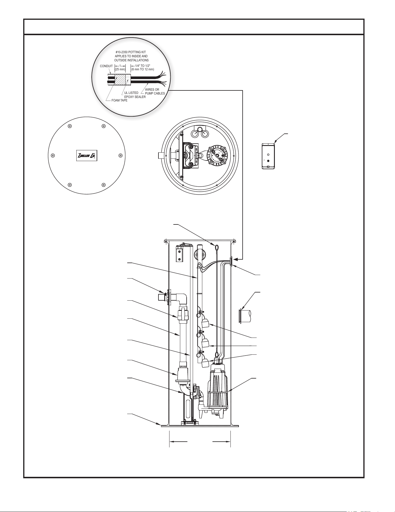
Typical Outdoor Grinder Pumping System Installation
All installations must comply with all applicable electrical and plumbing codes, including but not limited to the
National Electrical Code, local, regional and/or state plumbing codes, etc.
FIGURE 3.
R
LOUISVILLE, KY
SILENCE
INPUT 1
POWER
4" PIPE SEAL
(FIELD INSTALLED)
2" PIPE SEAL
(FIELD INSTALLED)
24" MIN.
FIBERGLASS AFD
1.25-2" Z-RAIL
2" CAST IRON CHECK VALVE
3/4" GUIDE RAILS
2" SCH. 80 BALL VALVE
2" FLEX BOOT FITTING
(LOCATION VARIES
WITH BASIN DEPTH)
FLOAT TREE ASSEMBLY
2HP GRINDER PUMP
2" PVC SCH. 80 PLBG.
1/8" 302 STAINLESS STEEL
LIFTING CABLE
ALARM
ON
OFF
SOLID FIBERGLASS COVER
HIGH WATER ALARM
OR SIMPLEX
CONTROL PANEL
(FIELD INSTALLED)
ALARM FLOAT SWITCH MUST OPERATE OFF LOW
VOLTAGE TO BE USED WITH QWIK BOX.
SK3110
FOAM TAPE
UL LISTED
EPOXY SEALER
#10-2350 POTTING KIT
APPLIES TO INSIDE AND
OUTSIDE INSTALLATIONS
CONDUIT
1
WIRES OR
PUMP CABLES
1/4" TO 1/2"
(25 mm)
(6 mm TO 12 mm)
SK1661
LOCATION VARIES WITH BASIN DEPTH

9
© Copyright 2024 Zoeller
®
Co. All rights reserved.
Outdoor Prepackaged System Installation Instructions
1. Review the drawing in Fig. 3 on page 8 and the actual system to
become familiar with the components in the packaged grinder pump
system. Review where the unit will be installed. Determine where
the power feed, inlet pipe, and discharge pipe will be located.
2. Remove the unit from packing. Prepackaged outdoor systems are
preassembled at the Zoeller Company and require a minimum of
eld assembly work. Float switches are set and tethered for proper
operation from the Factory. Systems using an automatic unit, WD
or WH series, have an integral “on/off” oat switch. See Fig. 4
on page 5 for adjustment instructions. The alarm switch should
be located 3” above the pump “on” level. Three oat systems
used with a control panel are placed at 27”, 24”, and 15” from the
bottom of the basin. Four oat systems used with a control panel
are placed at 33”, 27”, 24”, and 15” from the bottom of the basin.
If the invert location is at or below the level of the oat switches,
contact the factory.
3. Float switches are tied in place for shipping purposes on all model
prepackaged systems. Cut the cable tie around each oat switch
bulb or the unit will not operate properly. Verify that where the
oat switches are set will work for your application. Verifying that
the oat switches are set properly and will not hang up inside the
basin is the responsibility of the installing contractor.
4. Dig a hole for the basin. The hole should be at least 24” larger
in diameter than the basin diameter to provide 12” of backll all
around and deep enough to provide either 12” of compacted
backll or 6” when a concrete pad is required. Note: Care must
be taken when excavating in order to avoid underground utilities
and disturbance of existing structure foundations. The hole should
be located at least ten feet from adjacent structures. Additional
distance may be required to sufciently locate the basin outside
of the loading area of the adjacent structures.
5. The location of the inlet hub is determined by the depth of the inlet
pipe. The inlet hub must be used with 4” pipe. It is best to install
the inlet on the side of the basin opposite the oat switches. To
install, use a 4” hole saw to drill into the side of the basin at the
correct elevation. Center the hub inner diameter with the hole in
the basin. Attach the hub to the side of the basin using the sealant
and hardware provided.
6. The bottom of the excavation can now be properly backlled,
compacted and leveled. Set basin in hole. Ensure the removable
cover extends above the nished grade line and the grade slopes
away from the unit. Backll and subbase should be 1/8” –3/4” pea
gravel or 1/8” –1/2” crushed stone. (Reference basin installation
instructions included with unit.) Connect the 4” inlet pipe to the
inlet hub.
7. Pouring a concrete anchor around system can now be completed.
Basin should be lled with water when pouring concrete to minimize
movement of the system. Backll around basin with specied
media. Care should be used to avoid damaging components or
leaving voids when back lling. Refer to Basin installation reference
guide on more specic requirements.
8. PVC or HDPE discharge piping is connected to the 2” threaded
tting located in the basin sidewall. Support discharge piping with
sufcient backll.
9. Connect lift cable to top of pump. Lower the pump into basin ensuring
the discharge pipe bracket slides into the disconnect tting.
10. Note: The grinder basin is a sewage holding tank. Vent connection
should be installed in accordance with all national, state and local
plumbing codes.
11. Dig a trench for the electrical conduit. The conduit should be located
below the frost line. Follow all applicable electrical codes.
12. If using a junction box, connect the electrical conduit and wiring
according to instructions included in this manual and wiring diagram
in box. If a potting kit is provided with the junction box, follow the
instructions for sealing the conduit connection to the junction box.
If a potting kit is not provided, the conduit connection to the junction
box must be sealed.
13. Mount the control panel within sight of the system. Connect
oat switches and pump cords according to the “Pump Wiring
Instructions” found later in this manual and located inside the panel
enclosure.
14. Remove any debris from the basin. Using clean water, check the
system for proper operation.
15. Seal and secure the lid using the proper bolts and sealant when
using a lid without a formed gasket.
16. Test system for leaks and proper pump operation.
17. Record system start up data for future reference.
This set of instructions is for factory prepackaged outdoor grinder systems only. If this is a eld assembled outdoor system
you can use these instructions as a guideline. If this is an indoor system then go back to pages 6-7 in this manual that covers indoor systems.

10
© Copyright 2024 Zoeller
®
Co. All rights reserved.
Operation
GENERAL
Zoeller pumps are lubricated and tested at the factory prior to shipment
and require minimum pre-start-up maintenance.
Maximum operating temperature of pump liquid for grinder pumps must
not exceed 130 °F (54 °C).
These units are designed for intermittent duty sanitary sewage
applications. If pump is used to dewater areas or pump liquids with
heavy or abrasive materials, the warranty will be voided.
NAMEPLATE DATA
The nameplate, located on the top of pump, indicates specic information
about the construction of the pump. The model number and date code
information should be recorded on the front page in the “Owner’s
Information” section of this manual.
SHORT TERM STORAGE
Do not install pump until permanent electrical power is available and
system is operational. When not in use, the pump should be stored,
and the following is advised:
• Store pump inside whenever possible or cover with some type of protective
covering.
• Tape or seal in plastic bag the terminal ends of wire leads.
• Spray coat unpainted surfaces with rust inhibiting oil.
• The impeller should be rotated every six months in order to keep the
seals lubricated and not develop a permanent set.
If panel is to be stored, the following is advised:
• Store the panel inside whenever possible and leave in the shipping
box.
• All openings shall be sealed.
• Store in an upright position.
• Do not stack anything on top of panel.
START-UP PROCEDURE
Before placing the equipment into operation the following should be
checked:
• Clean pit.
• Pump, oat switches, electrical cables and junction box are dry and
properly installed.
• Electrical boxes dry, sealed and securely installed.
• Floats positioned properly.
• Discharge valves open.
• 3/16” vent hole drilled in pipe between check valve and pump.
Once the above has been veried proceed with the following checks:
• Pump power cables and control oats properly installed and voltage
veried.
• Conduit connections to panel and junction box are properly sealed.
• After installing the pump into the containment area, with adequate
submergence, open the discharge valve fully. Start the unit using
manual controls. If ow is appreciably less than rated performance,
pump may be air locked. To expel trapped air, jog the unit several
times, using the manual controls.
• Have a qualied electrician take voltage and current measurements
with the pump running. Record these readings in the space provided
in the “Owner’s Information” section on page 1 of this manual for
future reference.
ADJUSTMENT PROCEDURE
Pumps: No adjustments are required.
Floats: Refer to Fig. 4 on page 5 or to the panel wiring schematic for
desired location of each oat switch setting.
Valves: Discharge valves should be placed in the fully open position.
Systems should not be operated for extended periods of time
with the discharge valves partially closed due to damaging
the valve.
SHUTDOWN PROCEDURES
If a system is shutdown for more than six months, the following is
recommended:
Pumps: If pit is to remain dry, then the pump can remain in the pit.
With the pump in the pit, it should be operated for ve minutes
once every three months. If the pit is to remain wet, the pump
should be removed and stored as noted above.
Panels: The panel should have all openings sealed to prevent moisture
and dust from entering the enclosure. Prior to restarting system,
the panel should be inspected for presence of moisture and any
loose connections.
Valves: Consult the valve/actuator supplier for information concerning
these systems components.
11
© Copyright 2024 Zoeller
®
Co. All rights reserved.
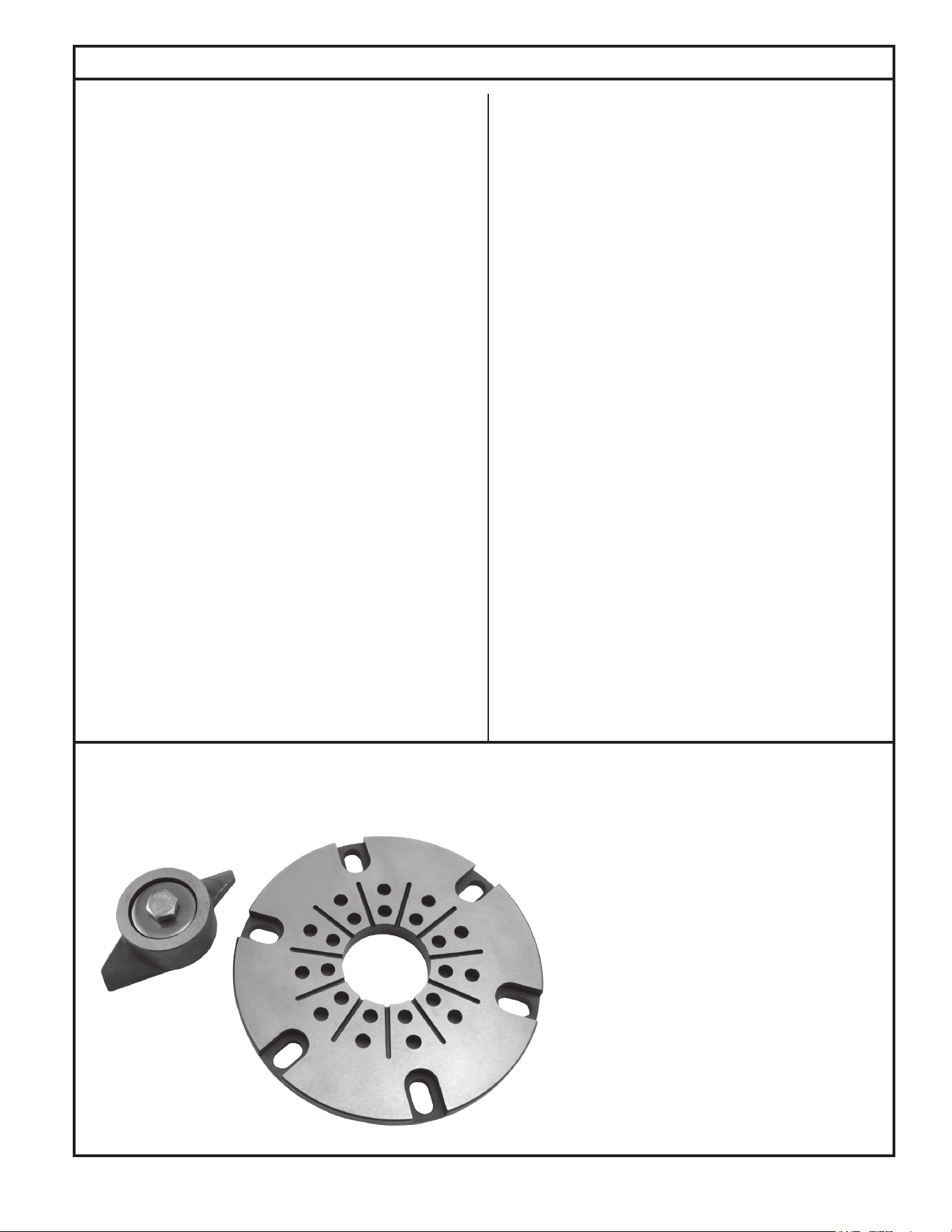
Cutter Maintenance
1. All power circuits must be disconnected and locked out before any
attempts are made at servicing. The cutter and disc can be removed
and sharpened by grinding the cutting faces. Both cutter and disc
must be removed from the pump. Removal of these parts can be
accomplished in the eld by removing pump from the sump and
positioning horizontally to access the intake of the pump. If seals or
other repairs are required, the pump must be totally removed and
serviced in a shop by a qualied pump technician or authorized
service center.
2. Remove the three countersunk screws on the ring.
3. Thoroughly clean the cutter and disc assembly. Tilt pump back to
the vertical position to make certain the end play has been removed.
Check and record the clearance between the cutter and disc with
a feeler gage. The correct running clearance is between 0.004" and
0.008".
4. With pump in horizontal position, heat the hex head bolt in the center
of the cutter with a propane torch. The bolt must be heated to 350°
F to soften the thread lock sealer on the bolt for ease of removal.
Remove the bolt by turning in a counterclockwise rotation. It will be
necessary to use a wood block to prevent the cutter from turning
while removing the bolt. Pull cutter from the shaft and remove the
spacer shims located behind the cutter.
5. Remove the six cap screws holding the disc and remove disc from
the pump.
6. The disc and cutter can be replaced with new service parts or
resurfaced by grinding. Resurfacing is accomplished by surface
grinding both disc and cutter to a 32 micro nish. Do not attempt
grinding in the eld. Send parts to a qualied machine shop for repair.
The disc, cutter and shims are a matched set. Keep parts together.
Measure disc before and after resurfacing with micrometer and
record measurements.
7. After resurfacing, the disc and cutter must be at within 0.001". If
the disc has been surface ground, it will be necessary to remove
shims to compensate for the material removed from the disc. As a
starting point, remove shims of the same thickness as the amount
machined from the cutter disc (step 6 above). Final running clearance
must be between 0.004” and 0.008”. Be sure pump is in vertical
position and all end play has been removed before measuring.
8. Clean bottom of pump where disc is located and replace disc and
retainer screws. Torque to 63-67 in-lbs. Replace cutter with the
correct shims. Install washer and torque hex head bolt to 71-75 in.-
lbs. Apply Loctite 262 thread-lock sealant or equal to bolt threads
prior to insertion. Check running clearance with pump in vertical
position to remove end play. Clearance must be between 0.004" and
0.008" to obtain efcient grinding when pump is put back in service.
9. Replace six cap screws.
10. Check the oil in the motor housing before reinstalling. Contact the
factory if the oil has a milky appearance or burnt smell. The level
should be even with the ll plug when pump is in the upright position.
Add oil if required. Use insulating oil supplied by the factory.
FIGURE 6.
To remove cutter: Heat the center bolt to 350°F to
loosen Loctite
®
thread sealant.
Grind the Cutter and Disc seen here to a 32 micronish.
Surfaces must be at to within 0.001" T.I.R. Gap must be
between 0.007" and 0.012" on these parts.
12
© Copyright 2024 Zoeller
®
Co. All rights reserved.
General Maintenance
Service Checklist
Electrical precautions. Before servicing a grinder pump, always shut off the main power circuit. Make sure you are wearing
insulated protective sole shoes and not standing in water. Under ooded conditions, contact your local electric company or a qualied
licensed electrician for disconnecting electrical service to the pump prior to removal.
Grinder pumps contain oil which becomes pressurized and hot under operating conditions. Allow 2-1/2 hours after shut
down before servicing pump.
Condition
A. Pump will not start or run.
B. Motor overheats and trips on overload.
C. Pump will not shut off.
D. Pump operates but delivers little or no water.
E. Pump starts and stops too often.
F. Large red ashing light comes on at control box.
G. Grease and solids accumulate in pit around pump.
GENERAL SYSTEM INSPECTION
Before the system is placed into operation, it should be inspected by a
qualied technician.
Wiring and grounding must be in accordance
with the National Electrical Code and all applicable local codes
and ordinances.
LUBRICATION PROCEDURES
No lubrication is required.
If pumps are to be stored for more than six months, refer to short term
storage procedure in the Operation section.
PREVENTIVE MAINTENANCE
Preventive maintenance is recommended to ensure a long service
life from the product. Provided is a suggested maintenance schedule.
Every six months:
• Inspect and test system for proper operation.
• Check for proper and unobstructed oat operation.
• Listen for proper check valve operation.
Every 5 years or 10,000 hours of operation:
• Remove pump, inspect and service using a Zoeller rebuild kit.
• Flush and clean basin.
Repair and service should be performed by a Zoeller
Pump Company Authorized Service Station only.
SAFETY PROCEDURES
For your protection, always disconnect pump
and panel from its power source before handling.
Never enter the basin until it has been properly
vented and tested. Any person entering a basin should be wearing
a harness with safety rope extending to the surface so that they can
be pulled out in case of asphyxiation. Sewage water gives off methane
and hydrogen sulde gases, both of which can be highly poisonous.
Installation and checking of electrical circuits and hardware should be
performed by a qualied electrician.
Pump is never to be lifted by power cord.
Unit must be cleaned and disinfected, inside the
pumping chamber and all exterior surfaces, prior to servicing.
Common Causes
Blown panel or circuit breaker fuse, low voltage, thermal overload open, de-
fective capacitor circuit, cutter or impeller clogged, oat switch held down or
defective, incorrect wiring in control panel, water in cap assembly.
Incorrect voltage, impeller or cutter blocked, negative head (discharge lower
than intake of pump). Defective “off” oat. Pump runs continuously at low water
level. Low oil level in motor shell.
Air lock, debris under oat assembly, defective switch, incoming sewage
exceeds capacity of pump.
Intake clogged with grease or sludge, pump air locked (clear vent hole), low or
incorrect voltage, clogged discharge line, operating near shut-off head.
Check valve stuck open or defective. Sump pit too small to handle incoming
sewage. Level control out of adjustment. Thermal overload tripping.
High water in pit. Check pump for clogging, or overload trip. On single phase
pumps, check the start capacitor in the control panel. See “A” and “D” above.
Break up solids and run pump with water running into the pit. Allow level to lower
to the pump intake. Continue until solids are cleared from the pit.
Do not drain kitchen grease down the sink.
If the above checklist does not uncover the problem, consult the factory. Do not attempt to service or otherwise disassemble pump. Service must be performed by
Zoeller Authorized Service Stations. Go to www.zoellerpumps.com/servicestations to nd the Authorized Service Station in your area.