A Crane Co. Company
INSTALLATION MANUAL
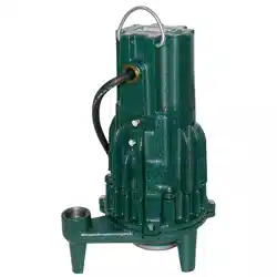
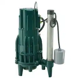
Submersible Centrifugal Grinder Pump
IMPORTANT! Read all instructions in this manual before operating pump.
As a result of Crane Pumps & Systems, Inc., constant product improvement program,
product changes may occur. As such Crane Pumps & Systems reserves the right to
change product without prior written notifi cation.
420 Third Street 83 West Drive, Bramton
Piqua, Ohio 45356 Ontario, Canada L6T 2J6
Phone: (937) 778-8947 Phone: (905) 457-6223
Fax: (937) 773-7157 Fax: (905) 457-2650
www.cranepumps.com
Form No. 140737-Rev. A
Series: PGPT
1 HP, 3450 RPM, 60 Hz.
Patent Pending
Manual Index
2
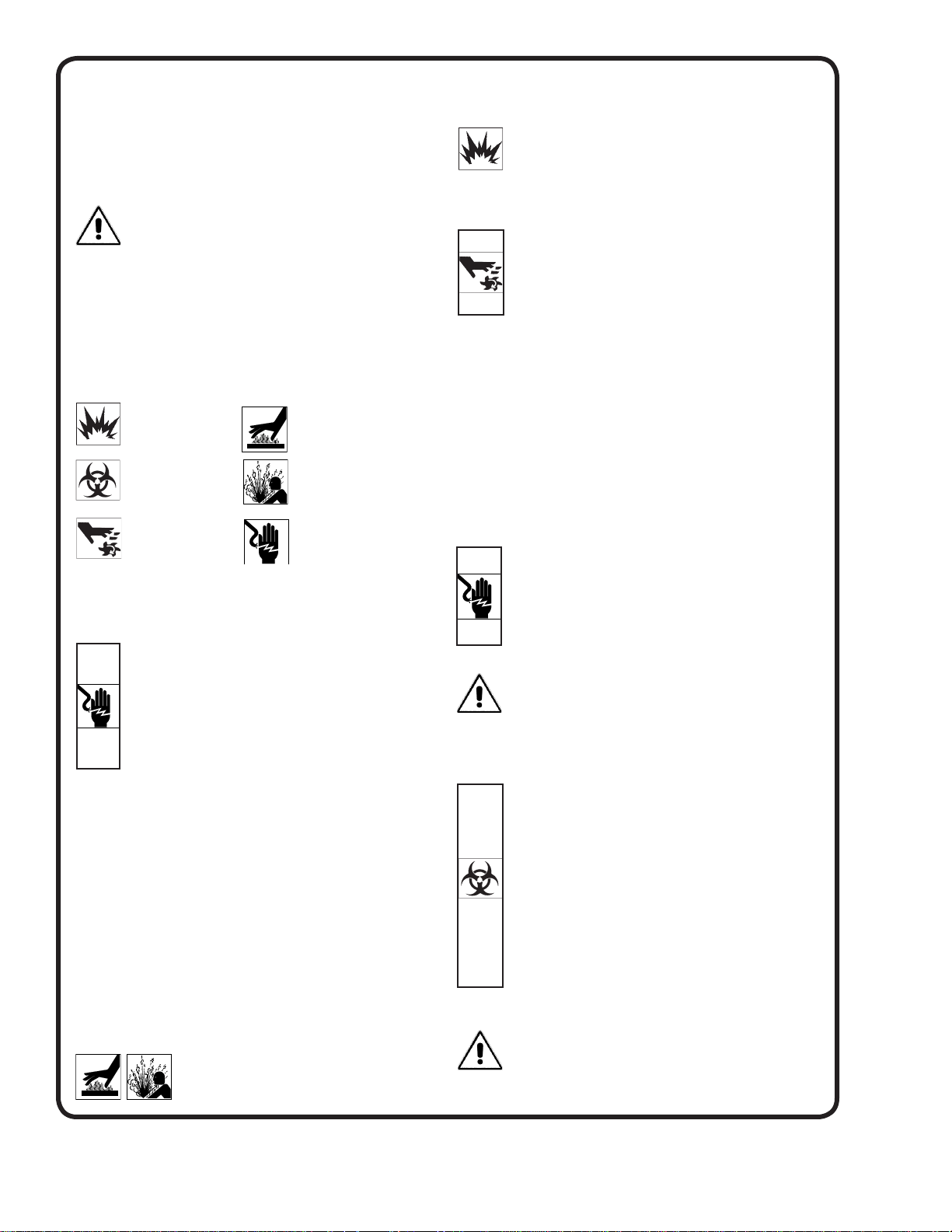
Please Read This Before Installing Or Operating Pump.
This information is provided for SAFETY and to PREVENT
EQUIPMENT PROBLEMS. To help recognize this information,
observe the following symbols:
IMPORTANT! Warns about hazards that can result
in personal injury orIndicates factors concerned with
assembly, installation, operation, or maintenance which
could result in damage to the machine or equipment if
ignored.
CAUTION ! Warns about hazards that can or will cause minor
personal injury or property damage if ignored. Used with symbols
below.
WARNING ! Warns about hazards that can or will cause serious
personal injury, death, or major property damage if ignored. Used
with symbols below.
Only qualifi ed personnel should install, operate and repair
pump. Any wiring of pumps should be performed by a qualifi ed
electrician.
WARNING ! - To reduce risk of electrical shock, pumps
and control panels must be properly grounded in
accordance with the National Electric Code (NEC) or the
Canadian Electrical Code (CEC) and all applicable state,
province, local codes and ordinances.
WARNING! - To reduce risk of electrical shock, always
disconnect the pump from the power source before
handling or servicing. Lock out power and tag.
Prevent large articles of clothing, large amounts of chemicals,
other materials or substances such as are uncommon in domestic
sewage from entering the system.
During power black-outs, minimize water consumption at the
home(s) to prevent sewage from backing up into the house.
Always keep the shut-off valve completely open when system is
in operation (unless advised otherwise by the proper authorities).
Before removing the pump from the basin, be sure to close the
shut-off valve. (This prevents backfl ow from the pressure sewer.)
Keep the control panel locked or confi ned to prevent unauthorized
access to it.
If the pump is idle for long periods of time, it is advisable to start the
pump occasionally by adding water to the basin.
CAUTION! Pumps build up heat and pressure
during operation-allow time for pumps to cool
before handling or servicing.
WARNING! - DO NOT pump hazardous materials
(fl ammable, caustic, etc.) unless the pump is specifi cally
designed and designated to handle them.
Do not block or restrict discharge hose, as discharge hose may
whip under pressure.
WARNING! - DO NOT wear loose clothing that may
become entangled in the impeller or other moving parts.
WARNING! - Keep clear of suction and discharge
openings. DO NOT insert fi ngers in pump with power
connected.
Make sure lifting handles are securely fastened each time before
lifting. Do not operate pump without safety devices in place. Always
replace safety devices that have been removed during service or
repair.
Do not exceed manufacturers recommendation for maximum
performance, as this could cause the motor to overheat.
Secure the pump in its operating position so it can not tip over,
fall or slide.
Cable should be protected at all times to avoid punctures, cut,
bruises and abrasions - inspect frequently.
Never handle connected power cords with wet hands.
To reduce risk of electrical shock, all wiring and junction
connections should be made per the NEC or CEC and
applicable state or province and local codes. Requirements
may vary depending on usage and location.
Submersible Pumps are not approved for use in swimming
pools, recreational water installations, decorative
fountains or any installation where human contact with
the pumped fl uid is common.
Do not remove cord and strain relief. Do not connect conduit to
pump.
Products Returned Must Be Cleaned, Sanitized, Or
Decontaminated As Necessary Prior To Shipment, To
Insure That Employees Will Not Be Exposed To Health
Hazards In Handling Said Material. All Applicable Laws
And Regulations Shall Apply.
Bronze/brass and bronze/brass fi tted pumps may contain
lead levels higher than considered safe for potable water
systems. Lead is known to cause cancer and birth
defects or other reproductive harm. Various government
agencies have determined that leaded copper alloys
should not be used in potable water applications. For
non-leaded copper alloy materials of construction, please
contact factory.
IMPORTANT! - Crane Pumps & Systems, Inc. is not responsible
for losses, injury, or death resulting from a failure to
observe these safety precautions, misuse or abuse of
pumps or equipment.
SAFETY FIRST!
Hazardous fl uids can
cause fi re or explo-
sions, burnes or death
could result.
Extremely hot - Severe
burnes can occur on contact.
Biohazard can cause
serious personal injury.
Hazardous fl uids can Hazard-
ous pressure, eruptions or ex-
plosions could cause personal
injury or property damage.
Rotating machinery
Amputation or severe
laceration can result.
Hazardous voltage can
shock, burn or cause death.
Other brand and product names are trademarks or registered trademarks of their respective holders.
® Barnes is a registered trademark of Crane Pumps & Systems Inc.
4/07 Alteration Rights Reserved

3
Congratulations on your purchase of a Barnes PGPT
Grinder Pump. With proper care and by following
a few simple guidelines your grinder pump will
give you many years of dependable service.
Use and Care
The Barnes PGPT Grinder Pump station is
designed to handle routine, domestic sewage.
Solid waste materials should be thrown in the
trash. While your station is capable of accepting
and pumping a wide range of materials,
regulatory agencies advise that the following
items should not be introduced into any sewer
either directly or through a kitchen waste
disposal:
• Glass
• Metal
• Diapers
• Socks, rags,cloth, or sanitary wipes
• Plastic objects (e.g., toys, utensils, etc.)
• Sanitary napkins or tampons
In addition you must NEVER introduce into any
sewer:
• Explosives
• Flammable Material
• Lubricating Oil and/or Grease
• Strong Chemicals
• Gasoline
General Information
Your home wastewater disposal service is
part of a low pressure sewer system. The key
element in this system is the grinder pump
station. The basin collects all wastewater from
the house. The solids in the sewage are then
ground to a small size suitable for pumping in
the slurry.
The grinder pump generates suffi cient
pressure to pump this slurry from your home
to the wastewater plant.
Power Failure
Your grinder pump cannot dispose of
wastewater or provide an alarm signal without
electrical power. If electrical power service is
interrupted, keep water usage to a minimum.
Warranty
Your grinder pump is furnished with a warranty
against defects in material or workmanship.
A properly completed Start-Up/Warranty
Registration form must be on fi le at the Barnes
factory in order to activate your warranty.
In addition your pump must be installed in
accordance with the installation instructions.
If you have a claim under the provisions of the
warranty, contact your local Barnes Distributor.
When contacting your representative for service,
please include your station serial number,
pump model number, and pump serial number.
For future reference, record the following
information:
Station Serial No: ______________________
Pump Model No: ______________________
Pump Serial No: _______________________
Local Distributor: _______________________
Distributor Telephone: ___________________
Submersible Centrifugal Grinder Pump
USER GUIDE
4
DISCHARGE ....................... 1¼” NPT SCH 80, 300 Series SS
CHECK VALVE ................... 1¼” NPT Cast Iron
Style ................ Flapper with Integrated Anti-Siphon
LIQUID TEMPERATURE .... 104°F (40°C) Continuous
MOTOR HOUSING ............. Cast Iron ASTM A-48, Class 30
VOLUTE .............................. Cast Iron ASTM A-48, Class 30
SEAL PLATE ...................... Cast Iron ASTM A-48, Class 30
IMPELLER .......................... Stainless Steel
SHREDDING RING ............. Hardened 440C Stainless Steel
Rockwell® C-55
CUTTER .............................. Hardened 440C Stainless Steel
Rockwell® C-55
SHAFT ................................. 416 Stainless Steel
SQUARE RING ................... Buna-N
O-RINGS ............................. Buna-N
HARDWARE ....................... 300 Series Stainless Steel
PAINT .................................. Air Dry Enamel
SEAL Design ............. Single Mechanical, oil fi lled reservoir
Material ........... Rotating Face - Silicon-Carbide
Stationary Face - Silicon-Carbide
Elastomer - Buna-N
Hardware - 300 Series Stainless Steel
CORD ENTRY ..................... 20ft. (6m) Cord with Plug,
Custom Molded Quick Connect
for Sealing with Strain Relief.
CORD .................................. 14/3 CSA/UL Approved SOW
SPEED ................................ 3450 RPM, 60Hz
UPPER BEARING:
Design ............. Single Row, Oil Lubricated
Load ................ Radial
LOWER BEARING
Design ............. Single Row, Oil Lubricated
Load ................ Radial & Thrust
MOTOR Design ............. NEMA L, Oil Filled,
Squirrel Cage Induction
Insulation ........ Class F
Type ................ Capacitor start/capacitor run
LEVEL CONTROLS:
A Series .......... Pipe Mounted, Piggy-Back
Mechanical with 240V Plug
OPTIONAL EQUIPMENT .... Additional cord
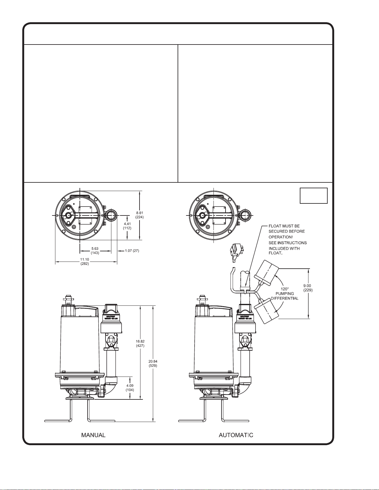
PUMP SPECIFICATIONS:
inches
(mm)
5
MODEL
NO
HP VOLT PH NEMA
START
CODE
FULL
LOAD
AMPS
LOCKED
ROTOR
AMPS
CORD
SIZE
CODE
TYPE
CORD
O.D.
± .02 (.5)
in (mm)
WINDING
RESISTANCE
MAIN -- START
(ohms)
PGPT1022 1 240 1 K
12.5 35.0 14/3 SOW
.61 (15.5)
1.5 - 3.3
PGPT1022A 1 240 1 K
12.5 35.0 14/3 SOW
.61 (15.5)
1.5 - 3.3
Winding Resistance ± 5%, measured from terminal block.
Pump rated for operation at ± 10% voltage at motor.
Recommended Breaker Sizes
Pump Model HP Phase Volts Breaker Size
ALL PGPT Models 1 1 240 15 AMP
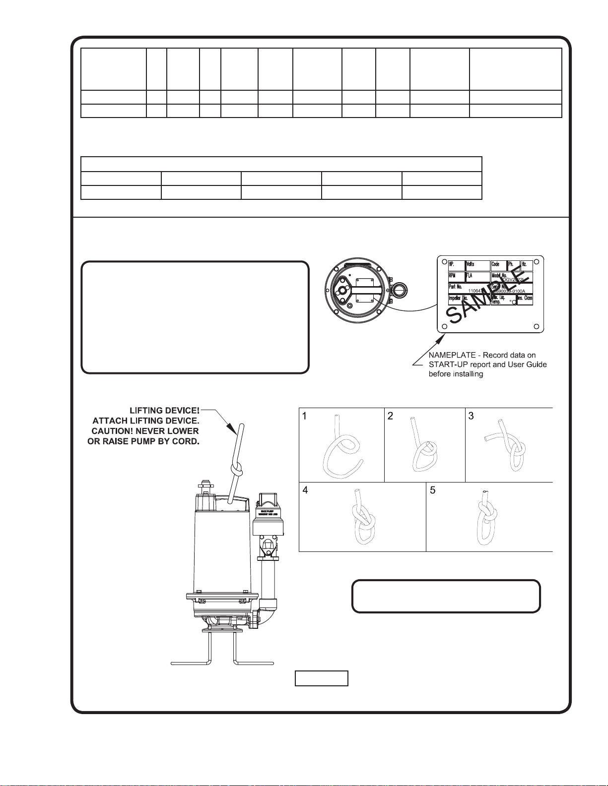
FIGURE 1
The nameplate is located on top of the pump.
This contains the pumps part number, horsepower
voltage, phase, and serial number, as well as other
information. The start-up form located in the back of
this manual contains a place to record this data. The
information should be recorded now so the pump
does not have to be pulled again later. The start-up
form can be left in the control panel until station start-
up is completed later.
Tie the bowline knot on lifting handle per
the directions provided (Steps 1 through 5).
6
RECEIVING/UNPACKING:
Upon receiving the pump, it should be inspected for dam-
age or shortages. If damage has occurred, fi le a claim
immediately with the company that delivered the pump.
Unpack pump and record pump serial and model number
before installing. If the manual is removed from the pack-
aging, do not lose or misplace.
STORAGE:
Short Term- For best results, pumps can be retained in
storage, as factory assembled, in a dry atmosphere with
constant temperatures for up to six (6) months.
Long Term- Any length of time exceeding six (6) months,
but not more than twenty-four (24) months. The units
should be stored in a temperature controlled area, a roofed
over walled enclosure that provides protection from the
elements (rain, snow, wind-blown dust, etc.), and whose
temperature can be maintained between 4°C and 49°C.
If extended high humidity is expected to be a problem, all
exposed parts should be inspected before storage and all
surfaces that have the paint scratched, damaged, or worn
should be recoated with a air dry enamel paint. All surfaces
should then be sprayed with a rust-inhibiting oil.
Pump should be stored in its original shipping container.
On initial start up, rotate impeller by hand to assure seal
and impeller rotate freely. If it is required that the pump be
installed and tested before the long term storage begins,
such installation will be allowed provided:
1.) The pump is not installed under water for more than
one (1) month.
2.) Immediately upon satisfactory completion of the
test, the pump is removed, thoroughly dried,
repacked in the original shipping container, and
placed in a temperature controlled storage area.
3.) Before placing pump into service, pump should be
brought to operational temperature range.
Excessive or direct heating or cooling should NOT
be used.
OPERATION TEMPERATURE RANGE: 2ºC to 40ºC.
SERVICE CENTERS:
For the location of the nearest Barnes Service Center, check
your Barnes representative:
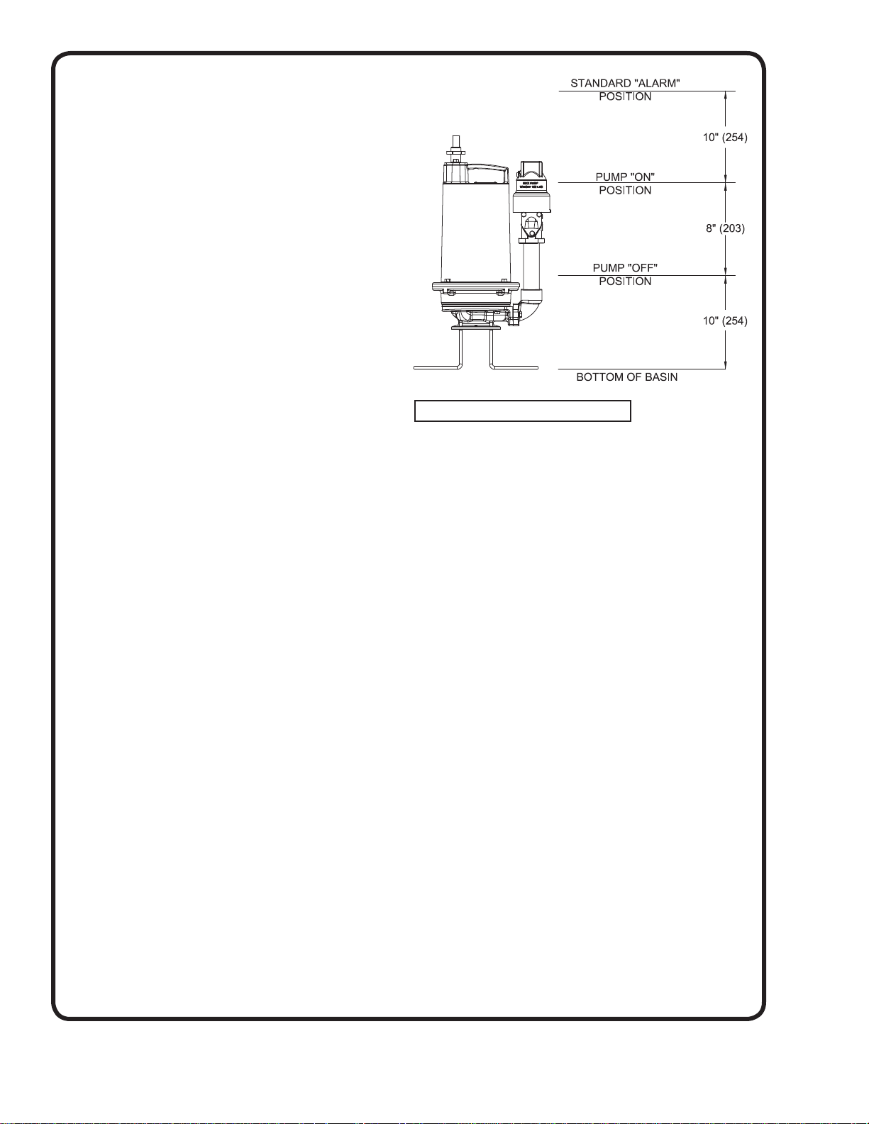
INSTALLATION:
Location - The pump is designed to fi t into your basin by
being mounted on a pump base. THIS PUMP MUST BE
INSTALLED WITH A MINIMUM OF 75MM AND A
MAXIMUM OF 115MM OF CLEARANCE UNDER THE
PUMP FOR THE ENTRANCE OF SEWAGE SOLIDS.
Discharge - Assemble discharge piping or hose assembly
(whichever is required by your application), to the pump.
Discharge piping should be as short as possible. Both a
check valve and a shut-off valve are required for each pump
being used. The check valve is used to prevent backfl ow
into the sump. Excessive backfl ow can cause fl ooding and/
or damage to the pump. The shut-off valve is used to stop
system fl ow during pump or check valve servicing.
Package Systems- Refer to manual supplied with basin
package system.
ELECTRICAL CONNECTIONS:
Pump Cables - The cord assembly mounted to the pump
must NOT be modifi ed in any way except for shortening
to a specifi c application. Any splice between the pump
and the control panel must be made in accordance with
the National Electric Code or the Canadian Electric
Code and all applicable state, province and local electric
codes. It is recommended that a junction box, be mounted
outside the sump or be of at least Nema 4 (EEMAC-4)
construction if located within the wet well. DO NOT USE
THE POWER OR CONTROL CABLES TO LIFT PUMP!
Overload Protection - The type of in-winding overload
protector used is referred to as an inherent overheating
protector and operates on the combined effect of
temperature and current. This means that the overload
protector will trip out and shut the pump off if the windings
become too hot, or the load current becomes too high.
It will then automatically reset and start the pump after
the motor cools to a safe temperature. In the event
of an overload, the source of this condition should be
determined and rectifi ed immediately. DO NOT LET THE
PUMP CYCLE OR RUN IF AN OVERLOAD CONDITION
OCCURS !
FIGURE 2 - Normal Operating Points
7
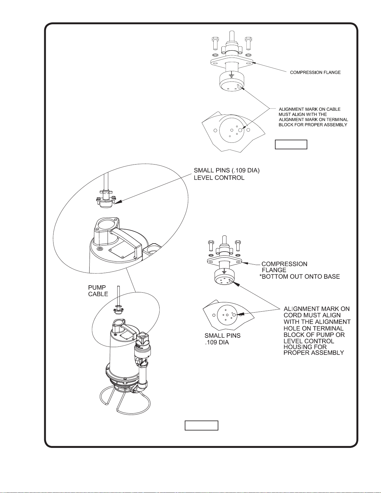
FIGURE 3
Wire Size - If additional cable is required consult a
qualifi ed electrician for proper wire size.
CABLE CONNECTIONS:
Pump Cable- Insert female end of cable plug into housing
bore aligning alignment mark with hole in terminal block
see Figures 4 & 5. Tighten bolts on compression fl ange
until fl ush with motor housing.
FIGURE 4
8
FIGURE 5
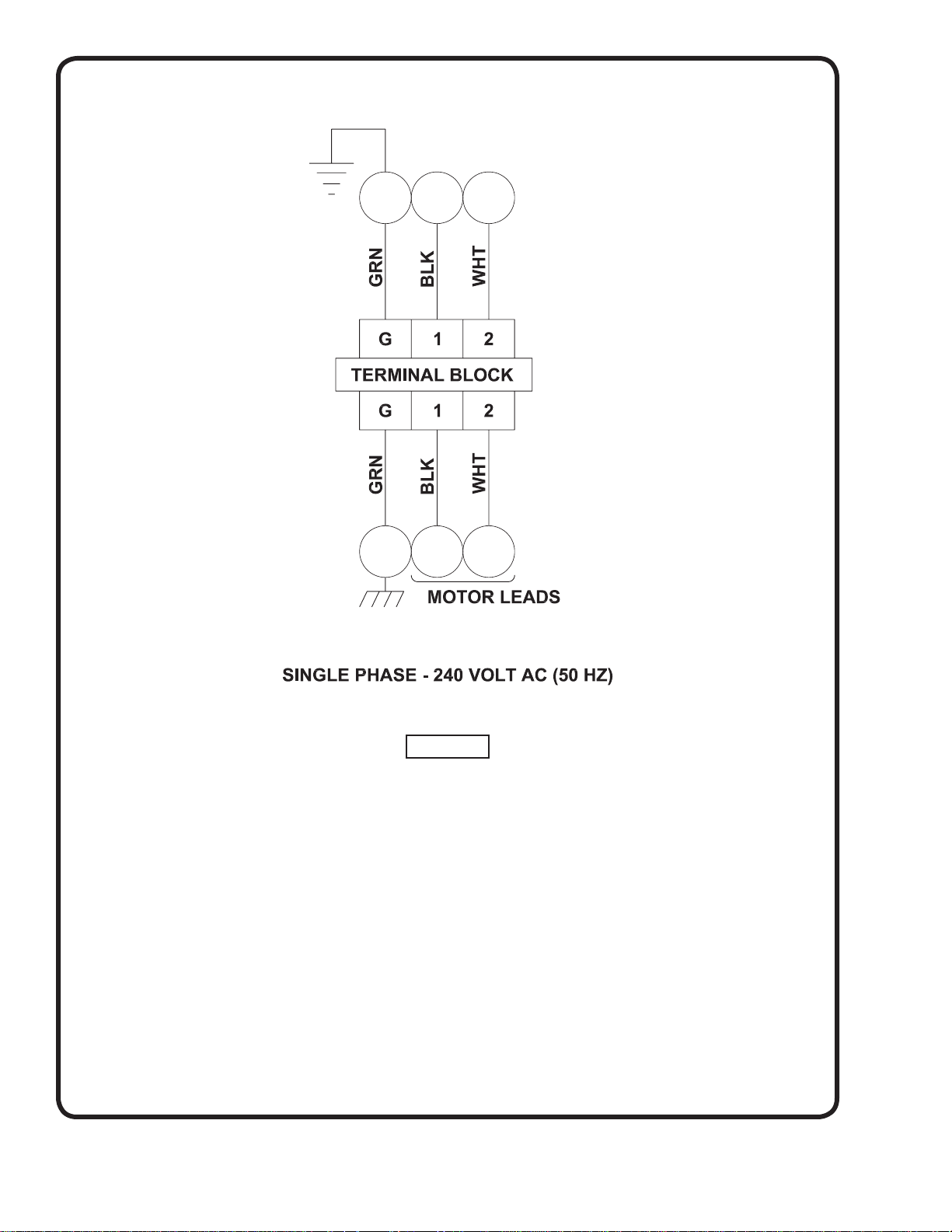
WIRING DIAGRAM

9
TROUBLE SHOOTING
CAUTION ! Always disconnect the pump from the electrical power source before handling.
If the system fails to operate properly, carefully read instructions and perform maintenance recommendations.
If operating problems persist, the following chart may be of assistance in identifying and correcting them:
MATCH “CAUSE” NUMBER WITH CORRELATING “CORRECTION” NUMBER.
NOTE: Not all problems and corrections will apply to each pump model.
PROBLEM C
AUSE CORRECTION
Pump will not run 1. Poor electrical connection, blown fuse,
tripped breaker or other interruption of power,
improper power supply.
2. Motor or switch inoperative (to isolate
cause, go to manual operation of pump).
2a. Float movement restricted.
2b. Switch will not activate pump or is defec-
tive.
3a. Insuffi cient liquid level.
3b. Switch is unable to activate
1. Check all electrical connections for
security. Have electrician measure current
in motor leads, if current is within ±20%
of locked rotor Amps, impeller is probably
locked. If current is 0, overload may be
tripped. Remove power, allow pump to cool,
then recheck current.
2a. Reposition pump or clean basin as
required to provide adequate clearance for
fl oat.
2b. Disconnect level control. Set ohmmeter
for a low range, such as 100 ohms full scale
and connect to level control leads. Actuate
level control manually and check to see that
ohmmeter shows zero ohms for closed switch
and full scale for open switch. (Float Switch).
3a. Make sure liquid level is at least equal to
suggested turn-on point.
4. Recheck all sizing calculations to
determine proper pump size.
5. Check discharge line for restrictions,
including ice if line passes through or into
cold areas.
6. Remove and examine check valve for
proper installation and freedom of operation.
7. Open valve.
8. Check cutter for freedom of operation,
security and condition. Clean cutter and inlet
of any obstruction.
9. Loosen union slightly to allow trapped air
to escape.Verify that turn-off level of switch
is set so that the suction is always fl ooded.
Clean vent hole.
10. Remove & examine for damage. Replace
pump stator if required.
11. Repair fi xtures as required to eliminate
leakage.
12. Check pump temperature limits & fl uid
temperature.
13. Replace portion of discharge pipe with
fl exible connector.
14. Turn to automatic position.
15. Check for leaks around basin inlet and
outlets.
Pump will not turn off 2a. Float movement restricted.
2b. Switch will not activate pump or is defec-
tive.
4. Excessive infl ow or pump not properly sized
for application.
9. Pump may be airlocked.
14. H-O-A switch on panel is in “HAND” posi-
tion
Pump hums but does not run 1. Incorrect voltage
8. Cutter jammed or loose on shaft, worn or
damaged, inlet plugged.
Pump delivers insuffi cient capacity 1. Incorrect voltage.
4. Excessive infl ow or pump not properly sized
for application.
5. Discharge restricted.
6. Check valve stuck closed or installed
backwards.
7. Shut-off valve closed.
8. Cutter jammed or loose on shaft, worn or
damaged, inlet plugged.
9. Pump may be airlocked.
10. Pump stator damaged/torn.
Pump cycles too frequently or runs
periodically when fi xtures are not in use
6. Check valve stuck closed or installed
backwards.
11. Fixtures are leaking.
15. Ground water entering basin.
Pump shuts off and turns on indepen-
dent of switch, (trips thermal overload
protector). CAUTION! Pump may start
unexpectedly. Disconnect power supply.
1. Incorrect voltage.
4. Excessive infl ow or pump not properly sized
for application.
8. Cutter jammed, loose on shaft, worn or
damaged, inlet plugged.
12. Excessive water temperature.
Pump operates noisily or vibrates
excessively
4. Operating at too high a pressure.
5. Discharge restricted.
8. Cutter broken.
13. Piping attachments to buiding structure too
rigid or too loose.
10
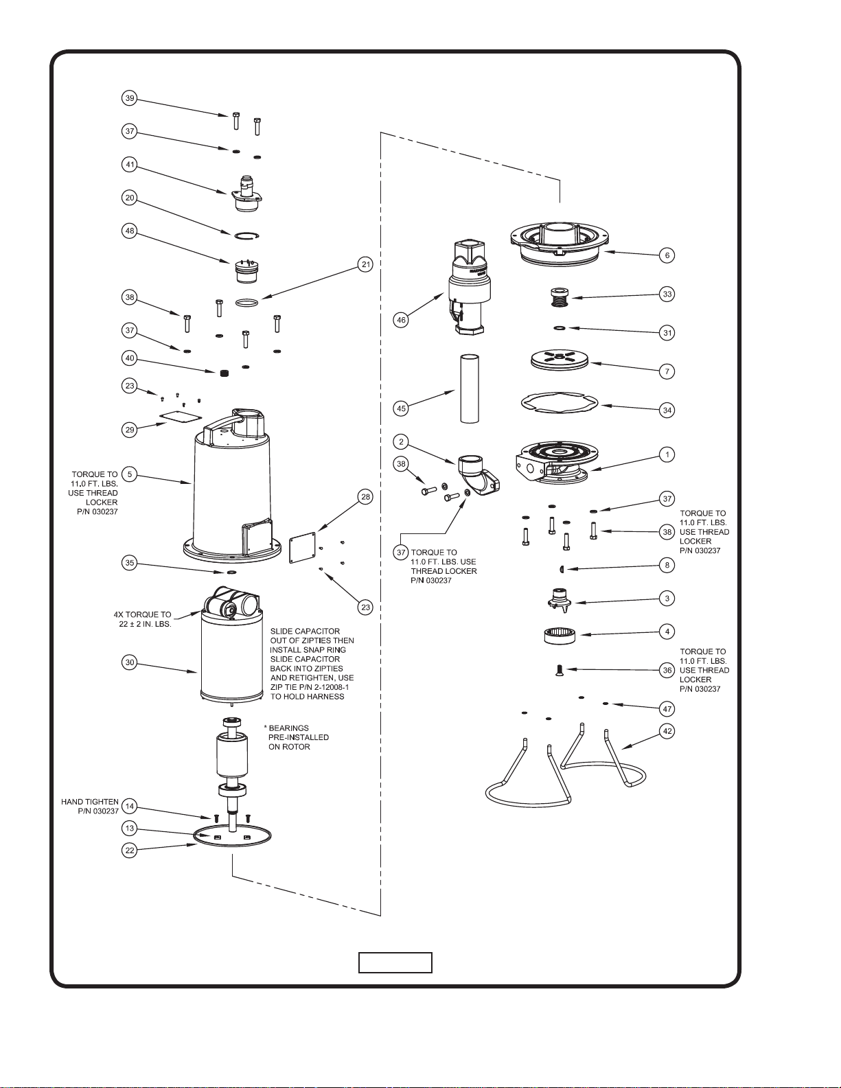
FIGURE 6
EXPLODED VIEW

11
PARTS LIST
Seal/Overhaul Kit .................. p/n 138085A
Cutter Kit ............................... p/n 138086A
Shim Kit ................................. p/n 138087A
ITEM QTY PART NO. DESCRITION
1 1 136566CT Casing, PGPT,CI
2 1 136574 Elbow,Discharge,CI,1.25
3 1 136561 Cutter,Radial,SS,2.015”
4 1 136564 Ring,Shred,SS,2.023”
5 1
1
110328
108342
Housing, Motor, Single (AU)
Housing, Motor, SIngle, (MAN)
6 1 136571B Plate, Seal, PGPT, Cast Iron
7 1 136569 Impeller, PGPT, 316 Stainless Steel
8 1 625-00583 Key,Woodruff,#405,.125
13 2 136572 Clip, Retaining,Bearing,STL
14 2 136931 Screw,FLHD,HS,8-32,.63,SS
15 1 110331 Handle,SS,4.50”X2.81”
20 2 105197 Ring, Retaining
21 2 2-31051-224 O-Ring, 2-224
22 1 095368 Seal,Tetra,TS33-261,Buna
23 8 001628 Screw,U,Drive,#4,.187
24 1 134127 Sensor Cable Terminal Block
25 1 113271 5 Pin Terminal Block (Power)
28 1 N/A Warning Plate
29 1 N/A Name Plate
30 1 136188A Motor,230V,60Hz,3450,CSCR
31 1 116442 Ring,Snap,5100-87
33 1 111131 Seal,Mech,.875”,C/CE/B
34 A/R
137023-001
137023-003
137023-005
137023-010
137023-020
Shim,0.001”
Shim,0.003”
Shim,0.005”
Shim,0.010”
Shim,0.020”
35 1 085326 Ring,Retain,5100-66
36 1 137077 Screw,FLHD,5/16-18,.88
37 16 026322 Washer,Lock,5/16
38 14 1-131-1 Screw,HXHD,5/16-18,1.25”
39 2 1-156-1 Screw,HXHD,5/16-18,1.000”
40 1 014270-SS Plug,Pipe,.375-18NPT,C’Sunk
41 1 105818XA Cord, 14/3, SOW
42 2 137083 Stand, Wire
45 1 104063 Nipple, Pipe, 1.25” x 6.00”
46 1 121583A Valve, Check, 1.25 NPT
47 4 140707 Retainer, Push, 5/16, 300 Series SS
48 1 103760 Terminal Block
49 5 2-12008-1 Zip Tie (Not Shown)
Contact your local Distributor or the Factory for other cord lengths and other optional equipment.
(**) For Manual model 10S2L

Notes

A Crane Co. Company
Limited 24 Month Warranty
Crane Pumps & Systems warrants that products of our manufacture will be free of defects in material and workmanship
under normal use and service for twenty-four (24) months after manufacture date, when installed and maintained
in accordance with our instructions.This warranty gives you speci• c legal rights, and there may also be other rights
which vary from state to state. In the event the product is covered by the Federal Consumer Product Warranties Law
(1) the duration of any implied warranties associated with the product by virtue of said law is limited to the same
duration as stated herein, (2) this warranty is a LIMITED WARRANTY, and (3) no claims of any nature whatsoever
shall be made against us, until the ultimate consumer, his successor, or assigns, noti• es us in writing of the defect,
and delivers the product and/or defective part(s) freight prepaid to our factory or nearest authorized service station.
Some states do not allow limitations on how long an implied warranty lasts, so the above limitation may not apply.
THE SOLE AND EXCLUSIVE REMEDY FOR BREACH OF ANY AND ALL WARRANTIES WITH RESPECT TO ANY
PRODUCT SHALL BE TO REPLACE OR REPAIR AT OUR ELECTION, F.O.B. POINT OF MANUFACTURE OR
AUTHORIZED REPAIR STATION, SUCH PRODUCTS AND/OR PARTS AS PROVEN DEFECTIVE. THERE SHALL BE
NO FURTHER LIABILITY, WHETHER BASED ON WARRANTY, NEGLIGENCE OR OTHERWISE. Unless expressly
stated otherwise, guarantees in the nature of performance speci• cations furnished in addition to the foregoing material
and workmanship warranties on a product manufactured by us, if any, are subject to laboratory tests corrected for
• eld performance. Any additional guarantees, in the nature of performance speci• cations must be in writing and such
writing must be signed by our authorized representative. Due to inaccuracies in • eld testing if a con! ict arises between
the results of • eld testing conducted by or for user, and laboratory tests corrected for • eld performance, the latter
shall control. RECOMMENDATIONS FOR SPECIAL APPLICATIONS OR THOSE RESULTING FROM SYSTEMS
ANALYSES AND EVALUATIONS WE CONDUCT WILL BE BASED ON OUR BEST AVAILABLE EXPERIENCE AND
PUBLISHED INDUSTRY INFORMATION. SUCH RECOMMENDATIONS DO NOT CONSTITUTE A WARRANTY OF
SATISFACTORY PERFORMANCE AND NO SUCH WARRANTY IS GIVEN.
This warranty shall not apply when damage is caused by (a) improper installation, (b) improper voltage (c) lightning
(d) excessive sand or other abrasive material (e) scale or corrosion build-up due to excessive chemical content. Any
modi• cation of the original equipment will also void the warranty. We will not be responsible for loss, damage or labor
cost due to interruption of service caused by defective parts. Neither will we accept charges incurred by others without
our prior written approval.
This warranty is void if our inspection reveals the product was used in a manner inconsistent with normal industry practice
and\or our speci• c recommendations. The purchaser is responsible for communication of all necessary information
regarding the application and use of the product. UNDER NO CIRCUMSTANCES WILL WE BE RESPONSIBLE FOR
ANY OTHER DIRECT OR CONSEQUENTIAL DAMAGES, INCLUDING BUT NOT LIMITED TO TRAVEL EXPENSES,
RENTED EQUIPMENT, OUTSIDE CONTRACTOR FEES, UNAUTHORIZED REPAIR SHOP EXPENSES, LOST
PROFITS, LOST INCOME, LABOR CHARGES, DELAYS IN PRODUCTION, IDLE PRODUCTION, WHICH DAMAGES
ARE CAUSED BY ANY DEFECTS IN MATERIAL AND\OR WORKMANSHIP AND\OR DAMAGE OR DELAYS IN
SHIPMENT. THIS WARRANTY IS EXPRESSLY IN LIEU OF ANY OTHER EXPRESS OR IMPLIED WARRANTY,
INCLUDING ANY WARRANTY OF MERCHANTABILITY OR FITNESS FOR A PARTICULAR PURPOSE.
No rights extended under this warranty shall be assigned to any other person, whether by operation of law or otherwise,
without our prior written approval.
420 Third Street 83 West Drive
Piqua, Ohio 45356 Brampton, Ont. Canada L6T 2J6
(937) 778-8947 (905) 457-6223
Fax (937) 773-7157 Fax (905) 457-2650
www.cranepumps.com
RETURNED GOODS
RETURN OF MERCHANDISE REQUIRES A “RETURNED GOODS AUTHORIZATION”.
CONTACT YOUR LOCAL CRANE PUMPS & SYSTEMS, INC. DISTRIBUTOR.
Products Returned Must Be Cleaned, Sanitized,
Or Decontaminated As Necessary Prior To Shipment,
To Insure That Employees Will Not Be Exposed To Health
Hazards In Handling Said Material. All Applicable Laws
And Regulations Shall Apply.
IMPORTANT!
WARRANTY REGISTRATION
Your product is covered by the enclosed Warranty.
To complete the Warranty Registration Form go to:
http://www.cranepumps.com/ProductRegistration/
If you have a claim under the provision of the warranty, contact your local
Crane Pumps & Systems, Inc. Distributor.

START-UP REPORT
General Information
Pump Owner’s Name: __________________________________________________________
Address: ____________________________________________________________________
Location of Installation: _________________________________________________________
Contact Person: __________________________________Phone: _______________________
Purchased From: _____________________________________________________________
Nameplate Data
Pump Model #: ___________________ Serial #: _____________________________________
Part #: __________________________ Impeller Diameter: ____________________________
Voltage: _________Phase: _____ Ø Hertz: ____________Horsepower: _______________
Full Load Amps: ___________________ Service Factor Amps: __________________________
Motor Manufacturer: ___________________________________________________________
Controls
Control panel manufacturer: _____________________________________________________
Model/Part number: ____________________________________________________________
Number of pumps operated by control panel: ________________________________________
Short circuit protection? YES___ NO___ Type: _________________________________
Number and size of short circuit device(s): ___________ Amp rating: ___________________
Overload Type: _____________ Size: ______________ Amp rating: ___________________
Do protection devices comply with pump and motor Amp rating? YES___ NO___
Are all electrical and panel entry connections tight? YES___ NO___
Is the interior of the panel dry? YES___ NO___
Liquid level Control Brand and Model: ______________________________________________
Pre-Startup
All Pumps
Type of equipment: NEW___ REBUILT___ USED___
Condition of equipment at Start-Up: DRY___ WET___ MUDDY___
Was Equipment Stored? YES___ NO___ Length of Storage: ______________________
Liquid being pumped: __________________ Liquid Temperature: _____________________
Supply Voltage/Phase/Frequency matches nameplate? YES___ NO___
Shaft turns freely? YES___ NO___
Direction of rotation verifi ed for 3Ø motors? YES___ NO___
Debris in piping or wet well? YES___ NO___
Debris removed in your presence? YES___ NO___
Pump case/wet well fi lled with liquid before startup? YES___ NO___
Is piping properly supported? YES___ NO___
Non-Submersible Pumps
Is base plate properly installed / grouted? YES___ NO___ N/A___
Coupling Alignment Verifi ed per I&O Manual? YES___ NO___ N/A___
Grease Cup/Oil Reservoir Level checked? YES___ NO___ N/A___
A Crane Co. Company

Submersible Pumps
Resistance of cable and pump motor (measured at pump control):
Red-Black:_______Ohms(•) Red-White:_______Ohms(•) White-Black:_______Ohms(•)
Resistance of Ground Circuit between Control Panel and outside of pump: __________Ohms(•)
MEG Ohms check of insulation:
Red to Ground: _________ White to Ground: __________ Black to Ground: ____________
Operational Checks
Is there noise or vibration present? YES___ NO___ Source of noise/vibration: ___________
Does check valve operate properly? YES___ NO___ N/A___
Is system free of leaks? YES___ NO___ Leaks at: ______________________________
Does system appear to operate at design ! ow rate? YES___ NO___
Nominal Voltage: _____________________ Phase: 1Ø 3Ø (select one)
Voltage Reading at panel connection, Pump OFF: L1, L2 _____ L2, L3 ____ L1, L3 _____
Voltage Reading at panel connection, Pump ON: L1, L2 ______ L2, L3 ____ L1, L3 _____
Amperage Draw, Pump ON: L1 ____________ L2 _____________ L3 _____________
Submersible Pumps
Are BAF and guide rails level / plumb? YES___ NO___
Is pump seated on discharge properly? YES___ NO___
Are level controls installed away from turbulence? YES___ NO___
Is level control operating properly? YES___ NO___
Is pump fully submerged during operation? YES___ NO___
Follow up/Corrective Action Required
YES___ NO___
Additional Comments:
____________________________________________________________________________
____________________________________________________________________________
____________________________________________________________________________
____________________________________________________________________________
____________________________________________________________________________
____________________________________________________________________________
____________________________________________________________________________
Startup performed by: _____________________ Date: ______________________________
Present at Start-Up
( ) Engineer: ____________________________ ( ) Operator: ________________________
( ) Contactor: ____________________________ ( ) Other: ___________________________
All parties should retain a copy of this report for future trouble shooting/reference
A Crane Co. Company
420 Third Street 83 West Drive
Piqua, Ohio 45356 Brampton, Ont. Canada L6T 2J6
(937) 778-8947 (905) 457-6223
Fax (937) 773-7157 Fax (905) 457-2650
www.cranepumps.com